

Page 1
Removing, Replacing and Upgrading
Memory in HP Kayak XU800 Models
IMPORTANT NOTE This text was updated in December 2000 and replaces all earlier
information on memory replacement in the HP Kayak XU800.
Replacing SDRAM
SDRAM was available on some XU800 models shipped before May 2000.
Following an announcement made by the Intel Corporation that SDRAM
memory should not be used with the Intel 840 chipset (the chipset used in
the Kayak XU800) HP is replacing all SDRAM memory already shipped with
RDRAM (RAMBUS DRAM) memory.
To determine whether you have SDRAM or RDRAM memory installed,
remove the cover of the PC. SDRAM models of the HP Kayak XU800 carry a
SDRAM Memory Expansion Card as shown below.
To carry out the conversion, you should contact HP Support. You will then
be able to upgrade with RDRAM memory as described here.
RDRAM Memory Expansion Card
SDRAM Memory Expansion Card (must be replaced by RDRAM)
Page 2
Replacing and Upgrading RDRAM Memory
There is a single Memory Expansion Card connector on the system board
for an RDRAM Memory Expansion Card.
NOTE Do not install a memory module directly into the connector for the
Memory Expansion Card on the system board.
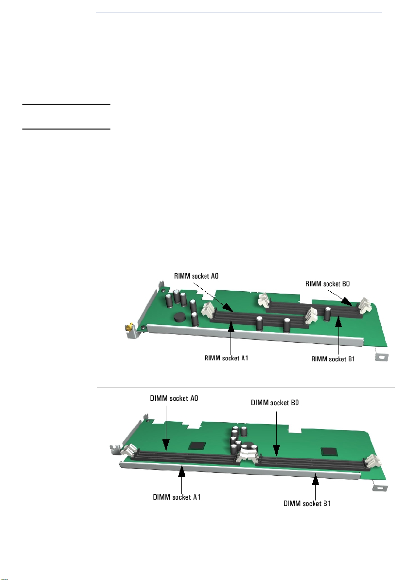
The RDRAM Memory Expansion Card supports 2 or 4 RDRAM Memory
Modules.
Note the following constraints:
• RDRAM modules must be installed in pairs. The first two sockets A0 and
B0, closest to the system board, contain the first pair of modules.
Upgrades are then installed in sockets A1 and B1.
• Pairs must be of identical modules. For instance if A0 contains a 256MB
PC800 ECC RDRAM then B0 must contain a 256MB PC800 ECC
RDRAM. For this reason, all HP memory accessories for the XM800
contain 2 identical modules.
• If sockets A1 and B1 are not used, an RDRAM Continuity Module must
be installed in both sockets.
Removing the
Memory Expansion
Card
Removing and Replacing the Memory Expansion Card
Switch off the display and PC Workstation. Disconnect all power cables
1
and any LAN or telecommunications cables.
Remove the PC Workstation’s cover (for further details, refer to the
2
User’s Guide).
Remove the HP UltraFlow Airflow Guide to obtain access to the RDRAM
3
Memory Expansion Card.
For ease of installation, place the PC Workstation on its side with the
4
system board facing upwards.
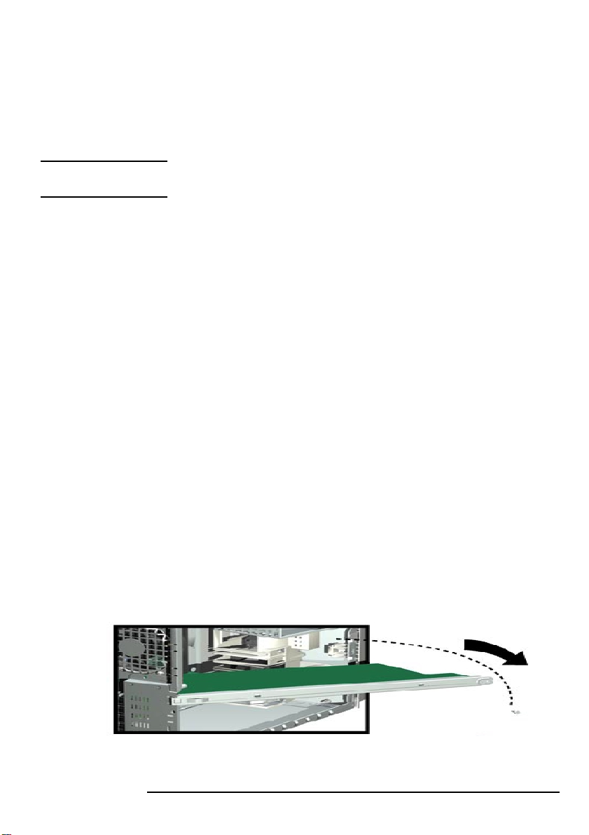
To access the Memory Expansion Card, remove the retaining bar that is
5
in front of it (remove the screw and swing the retaining bar outwards).
2
Page 3

Remove the two retaining screws holding the Memory Expansion Card
6
in place.
Open the two retaining clips on the Memory Expansion Card and remove
7
it from the connector.
Replacing the
Memory Expansion
Card
Install the Memory Expansion Card so that the memory modules face the
1
processor.
Ensure the Memory Expansion Card is al igned with the guide rail on the
2
fan and speaker assembly, and that the two notches on the Memory
Expansion Card are aligned with those of the Memory Card Connector
and accessory card panel.
With the two retaining clips open, press the Memory Expansion Card
3
completely into the two connectors on the system board until the
retaining clips click into position. Secure the Memory Expansion Card in
place with the two retaining screws.
Replace the retaining bar and secure it in place with the screw.
4
Return the PC Workstation to its upright position.
5
Re pla ce th e HP Ult raf low Airf low Gui de ( for f ull ins truc tio ns s ee p age 25
6
of the User’s Guide).
Replace the PC workstation’s cover. Reconnect the power and
7
telecommunications cables.
Removing and Replacing a Memory Module
NOTE Use only the HP memory modules provided for your PC model. The use of
memory modules from any previous PC computers is not supported. If you
want to find out about available accessories for your PC, refer to the HP
Accessories Web site at: http://www.hp.com/go/pcaccessories
Switch off the display and PC Workstation. Disconnect all power cables
1
and any LAN telecommunications cables.
Remove the PC workstation’s cover.
2
Remove the HP Ultraflow Airflow Guide (for full instructions, refer to
3
page 25 of the User’s Guide).
3
Page 4

NOTE For PC Workstations with an onboard RIMM, place the PC on its side with
the system board facing upwards for ease of installation..
For PC Workstations with a Memory Expansion Card, install memory
modules directly onto the card without removing it from the system board.
If you intend to:
4
Install a Memory Module:
a
For RIMM modules, unused memory sockets contain a continuity
module. Open the two retaining clips and remove the continuity
module from the socket. Store it for future use.
Replace a Memory Module:
b
Open the two retaining clips and remove the old memory module.
Ensure t he two notches of the Memory Module are al igned with those of
5
the socket. With the two retaining clips ope n, press the memory module
completely into the socket until the retaining clips click into position.
Replace the HP Ultraflow Airflow Guide.
6
Replace the PC Workstation’s cover. Reconnect all the power and
7
telecommunications cables.
Check the HP summary screen to verify the new configuration (this
8
operation is described on page 17 of the User’s Guide).
4
 Loading...