

Page 1
HP Kayak
PC Workstation
Service Handbook
PC Workstations and
Accessories
4th Edition
June 2000
Page 2
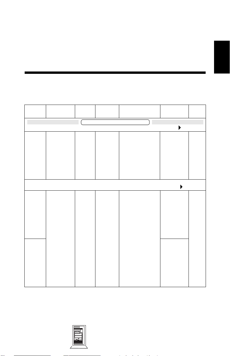
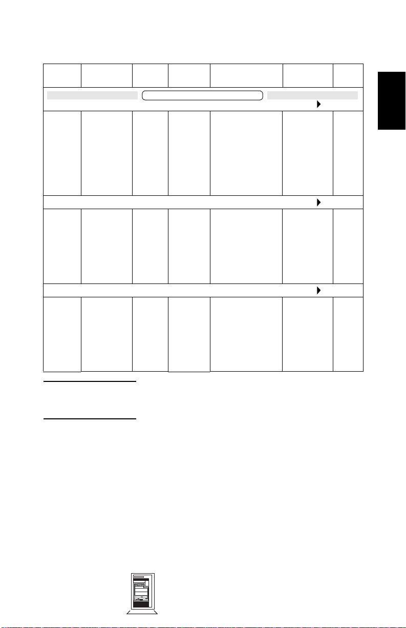
HP Kayak XU Series 04xx and HP Kayak XW Series 04xx
Models and Accessories
2
2
Product
Number
D6331N
and
D6331T
D6333N
and
D6333T
D6334N
and
D6334T
Processors Std.
RAM
HP Kayak XU 6/400 MHz - 512 KB (Series 0441) (CPL: 8/98 )
Single
Pentium®
II Xeon™
processor
with 512 KB
of L2 cache
memory
HP Kayak XU 6/450 MHz - 512 KB (Series 0441) (CPL: 10/98 )
Single
Pentium
II Xeon
processor
with 512 KB
of L2 cache
memory
Kayak XU 6/xxx PC Workstation
128 MB
SDRAM
ECC
128 MB
SDRAM
ECC
Hard
Drive
4.5 GB
10k rpm
SCSI
4.5 GB
10k rpm
SCSI
Video Controller Multi-
media
ELSA GLoria
Synergy AGP,
8 MB on board,
not upgradable.
ELSA GLoria
Synergy AGP,
8 MB on board,
not upgradable.
32X IDE
CD-ROM.
Audio chip
(AD1816) is
integrated
on the
system
board.
32X IDE
CD-ROM.
Audio chip
(AD1816) is
integrated
on the
system
board
CD-RW
CD-ROM.
Audio chip
(AD1816) is
integrated
on the
system
board
LAN
10BT/
100TX
10BT/
100TX
Mini-Tower
PC Workstations
HP Kayak XU Series 04xx and HP Kayak XW Series
04xx 2-1
Page 3
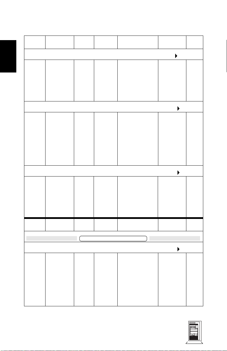
HP Kayak XU Series 04xx and HP Kayak XW Series 04xx
2
Product
Number
D6335N
and
D6335T
D6336N
and
D6336T
D6337N
and
D6337T
Product
Number
Processors Std.
HP Kayak XU 6/450 MHz - 1 MB (Series 0441) (CPL: 03/99 )
Single
Pentium
II Xeon
processor
with 1 MB of
L2 cache
memory
HP Kayak XU 6/450 MHz - 512 KB (Series 0403) (CPL: 12/98 )
Single
Pentium
II Xeon
processor
with 512 KB
of L2 cache
memory
HP Kayak XU 6/450 MHz - 512 KB (Series 0462) (CPL: 11/99 )
Single
Pentium
II Xeon
processor
with 512 KB
of L2 cache
memory
Processors Std.
RAM
128 MB
SDRAM
ECC
128 MB
SDRAM
ECC
128 MB
SDRAM
ECC
RAM
Hard
Drive
9.1 GB
10k rpm
SCSI
9.1 GB
10k rpm
SCSI
9.1 GB
10k rpm
SCSI
Hard
Drive
Video Controller Multi-
ELSA GLoria
Synergy AGP,
8 MB on board,
not upgradable.
Matrox
Millennium G200
8 MB video
memory fitted.
Upgradable to
16 MB of memory.
AccelGalaxy AGP.
31 MB of video
memory. Not
upgradable.
Video Controller Multi-
media
CD-RW.
Audio chip
(AD1816) is
integrated
on the
system
board
32✕ Max
IDE
CD-ROM.
Audio chip
(AD1816) is
integrated
on the
system
board
CD-RW.
Audio chip
(AD1816) is
integrated
on the
system
board
media
LAN
10BT/
100TX
10BT/
100TX
10BT/
100TX
LAN
Kayak XU 7/xxx PC Workstation
HP Kayak XU 7/500 MHz - 512 KB (Series 0403) (CPL: 03/99 )
D6340N
D6340T
2-2 HP Kayak XU Series 04xx and HP Kayak
XW Series 04xx
and
Single
Pentium
III Xeon
processor
with 512 KB
of L2 cache
memory
128 MB
SDRAM
ECC
9.1 GB
10k rpm
SCSI
Matrox
Millennium G200
8 MB video
memory fitted.
Upgradable to
16 MB of memory.
Mini-Tower
PC Workstations
32✕ Max
IDE
CD-ROM.
Audio chip
(AD1816) is
integrated
on the
system
board
10BT/
100TX
Page 4

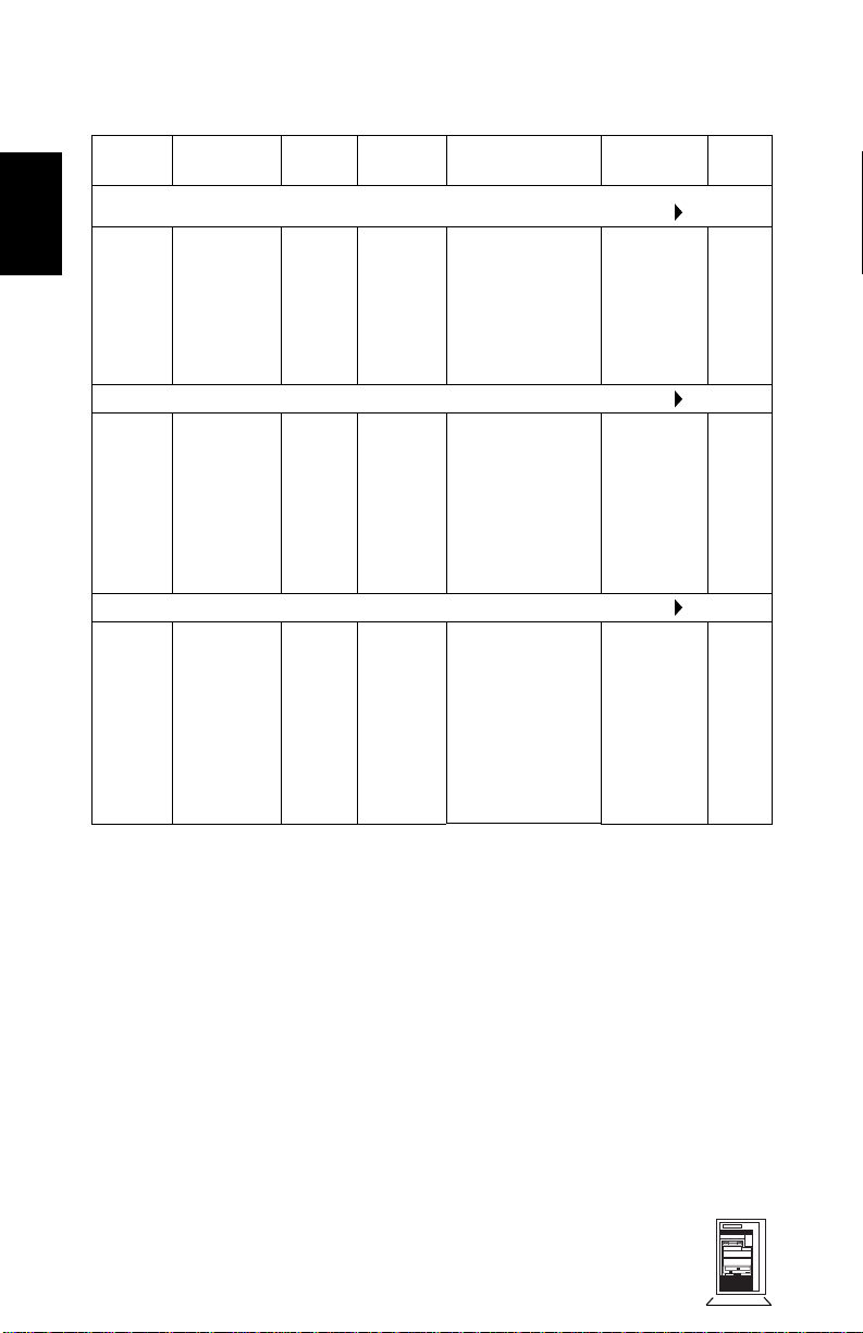
HP Kayak XU Series 04xx and HP Kayak XW Series 04xx
Product
Number
D6341N
and
D6341T
D6342N
and
D6342T
D6343N
and
D6343T
Processors Std.
HP Kayak XU 7/500 MHz - 512 KB (Series 0441) (CPL: 03/99 )
Single
Pentium
III Xeon
processor
with 512 KB
of L2 cache
memory
HP Kayak XU 7/500 MHz - 512 KB (Series 0462) (CPL: 03/99 )
Single
Pentium
III Xeon
processor
with 512 KB
of L2 cache
memory
HP Kayak XU 7/500 MHz - 512 KB (Series 0490) (CPL: 03/99 )
Single
Pentium
III Xeon
processor
with 512 KB
of L2 cache
memory
RAM
128 MB
SDRAM
ECC
256 MB
SDRAM
ECC
256 MB
SDRAM
ECC
Hard
Drive
9.1 GB
10k rpm
SCSI
9.1 GB
10k rpm
SCSI
9.1 GB
10k rpm
SCSI
Video Controller Multi-
ELSA GLoria
Synergy AGP,
8 MB on board,
not upgradable
AccelGalaxy AGP.
31 MB of video
memory. Not
upgradable
Matrox
Productiva
G100-Quad
media
CD-RW.
Audio chip
(AD1816) is
integrated
on the
system
board
CD-RW.
Audio chip
(AD1816) is
integrated
on the
system
board
32X IDE
CD-ROM.
Audio chip
(AD1816) is
integrated
on the
system
board
LAN
10BT/
100TX
10BT/
100TX
10BT/
100TX
2
HP Kayak XU 7/550 MHz - 512 KB (Series 0441) (CPL: 05/99 )
D6345N
D6345T
Mini-Tower
PC Workstations
and
Single
Pentium
III Xeon
processor
with 512 KB
of L2 cache
memory
128 MB
SDRAM
ECC
9.1 GB
10k rpm
SCSI
ELSA GLoria
Synergy AGP,
8 MB on board,
not upgradable
HP Kayak XU Series 04xx and HP Kayak XW
32X IDE
CD-ROM.
Audio chip
(AD1816) is
integrated
on the
system
board
Series 04xx 2-3
10BT/
100TX
Page 5
HP Kayak XU Series 04xx and HP Kayak XW Series 04xx
2
Product
Number
D6346N
and
D6346T
D6347N
and
D6347T
D6348N
and
D6348T
Processors Std.
HP Kayak XU 7/550 MHz - 512 KB (Series 0462) (CPL: 05/99 )
Single
Pentium
III Xeon
processor
with 512 KB
of L2 cache
memory
HP Kayak XU 7/550 MHz - 512 KB (Series 0490) (CPL: 05/99 )
Single
Pentium
III Xeon
processor
with 512 KB
of L2 cache
memory
HP Kayak XU 7/550 MHz - 512 KB (Series 0403) (CPL: 05/99 )
Single
Pentium
III Xeon
processor
with 512 KB
of L2 cache
memory
RAM
256 MB
SDRAM
ECC
256 MB
SDRAM
ECC
128 MB
SDRAM
ECC
Hard
Drive
9.1 GB
10k rpm
SCSI
9.1 GB
10k rpm
SCSI
9.1 GB
10k rpm
SCSI
Video Controller Multi-
AccelGalaxy AGP.
31 MB of video
memory. Not
upgradable
Matrox
Productiva
G100-Quad
Matrox
Millennium G200
8 MB video
memory fitted.
Upgradable to
16 MB of memory
media
CD-RW.
Audio chip
(AD1816) is
integrated
on the
system
board
32X IDE
CD-ROM.
Audio chip
(AD1816) is
integrated
on the
system
board
32X IDE
CD-ROM.
Audio chip
(AD1816) is
integrated
on the
system
board
LAN
10BT/
100TX
10BT/
100TX
10BT/
100TX
2-4 HP Kayak XU Series 04xx and HP Kayak
XW Series 04xx
Mini-Tower
PC Workstations
Page 6
HP Kayak XU Series 04xx and HP Kayak XW Series 04xx
Product
Number
D6796N
and
D6796T
D6797N
and
D6797T
D6799N
and
D6799T
Processors Std.
HP Kayak XW 6/400 MHz - 512 KB (Series 0480) (CPL: 07/98 )
Single
Pentium II
Xeon
processor
with 512 KB
of L2 cache
memory
HP Kayak XW 6/450 MHz - 512 KB (Series 0480) (CPL: 09/98 )
Single
Pentium II
Xeon
processor
with 512 KB
of L2 cache
memory
HP Kayak XW 6/450 MHz - 512 KB (Series 0475) (CPL: 01/99 )
Single
Pentium II
Xeon
processor
with 512 KB
of L2 cache
memory
RAM
Kayak XW 6/xxx PC Workstation
128 MB
SDRAM
ECC
128 MB
SDRAM
ECC
128 MB
SDRAM
ECC
Hard
Drive
4.5 GB,
10k rpm,
SCSI
9.1 GB,
10k rpm,
SCSI
9.1 GB,
10k rpm,
SCSI
Video Controller Multi-
HP VISUALIZE
fx6 hardware
accelerator
HP VISUALIZE
fx6 hardware
accelerator
HP VISUALIZE
fx4+ hardware
accelerator
media
32X IDE
CD-ROM.
Audio chip
(AD1816) is
integrated
on the
system
board.
CD-RW.
Audio chip
(AD1816) is
integrated
on the
system
board.
CD-RW.
Audio chip
(AD1816) is
integrated
on the
system
board.
LAN
2
10BT/
100TX
10BT/
100TX
10BT/
100TX
NOTE: All models are supplied with a 1.44 MB Flexible Disk
Drive, an integrated Ultra Wide 16-bit SCSI controller,
and an integrated IDE controller.
Mini-Tower
PC Workstations
HP Kayak XU Series 04xx and HP Kayak XW
Series 04xx 2-5
Page 7

2
HP Kayak XU Series 04xx and HP Kayak XW Series 04xx
Supported Accessories
Memory Upgrades
SDRAM 64 MB 72bit 100MHz main memory (unbuffered ECC) D6522A
SDRAM 128 MB 72bit 100MHz main memory (unbuffered ECC) D6523A
SDRAM 256 MB 72bit 100MHz main memory (unbuffered ECC) D6743A
SDRAM 512 MB 72bit 100MHz main memory (registered ECC)
16 MB Hardware texture module for HP VISUALIZE fx4+ graphics board D5511B
32 MB Hardware texture module for HP VISUALIZE fx6 graphics board D6795A
1
D6742A
Dual Processor Kits
Intel Pentium II Xeon 400 MHz containing 512 KB internal L2 cache D6740A
Intel Pentium II Xeon 450 MHz containing 512 KB internal L2 cache D6741A
Intel Pentium II Xeon 450 MHz containing 1 MB internal L2 cache D6939A
Intel Pentium III Xeon 500 MHz containing 512 KB internal L2 cache D7513A
Intel Pentium III Xeon 550 MHz containing 512 KB internal L2 cache D7514A
Input Devices
HP mouse C3751B
Video Displays
All current HP Displays (see the HP Kayak Accessory Service Handbook)
Mass Storage—Hard disk drives
4.5 GB UW-SCSI hard disk 7.2k rpm (Low Profile) D5368B
4.5 GB UW-SCSI hard disk 10k rpm
9.1 GB UW-SCSI hard disk 10k rpm
18.1 GB UW-SCSI hard disk 10k rpm
9.1 GB UW-SCSI hard disk 7.2k rpm (Low Profile) D6938A
Removable Mass Storage
Flexible disk 3.5-inch 1.44 MB (1-inch high) D2035B
IDE 32✕ CD-ROM drive D4384A
CD-RW drive C4400A
2
3
(Low Profile)
3
(Low Profile) D6520A
3
(Low Profile) D7515A
D5481B
Miscellaneous
User’s Guide Manual D6339A
HP FastRAID2 Accessory Kit D6690A
1. Not compatible with non-registered ECC DIMMs. Available from December 1998 (to be
confirmed).
2. Dual Processor Kits include: processor, voltage regulator module and heatsink.
3. 10k rpm hard disk drives can only be installed in the two upper internal disk drive shelves.
They must not be installed in the lower front-access shelves.
2-6 HP Kayak XU Series 04xx and HP Kayak
XW Series 04xx
Mini-Tower
PC Workstations
Page 8
HP Kayak XU Series 04xx and HP Kayak XW Series 04xx
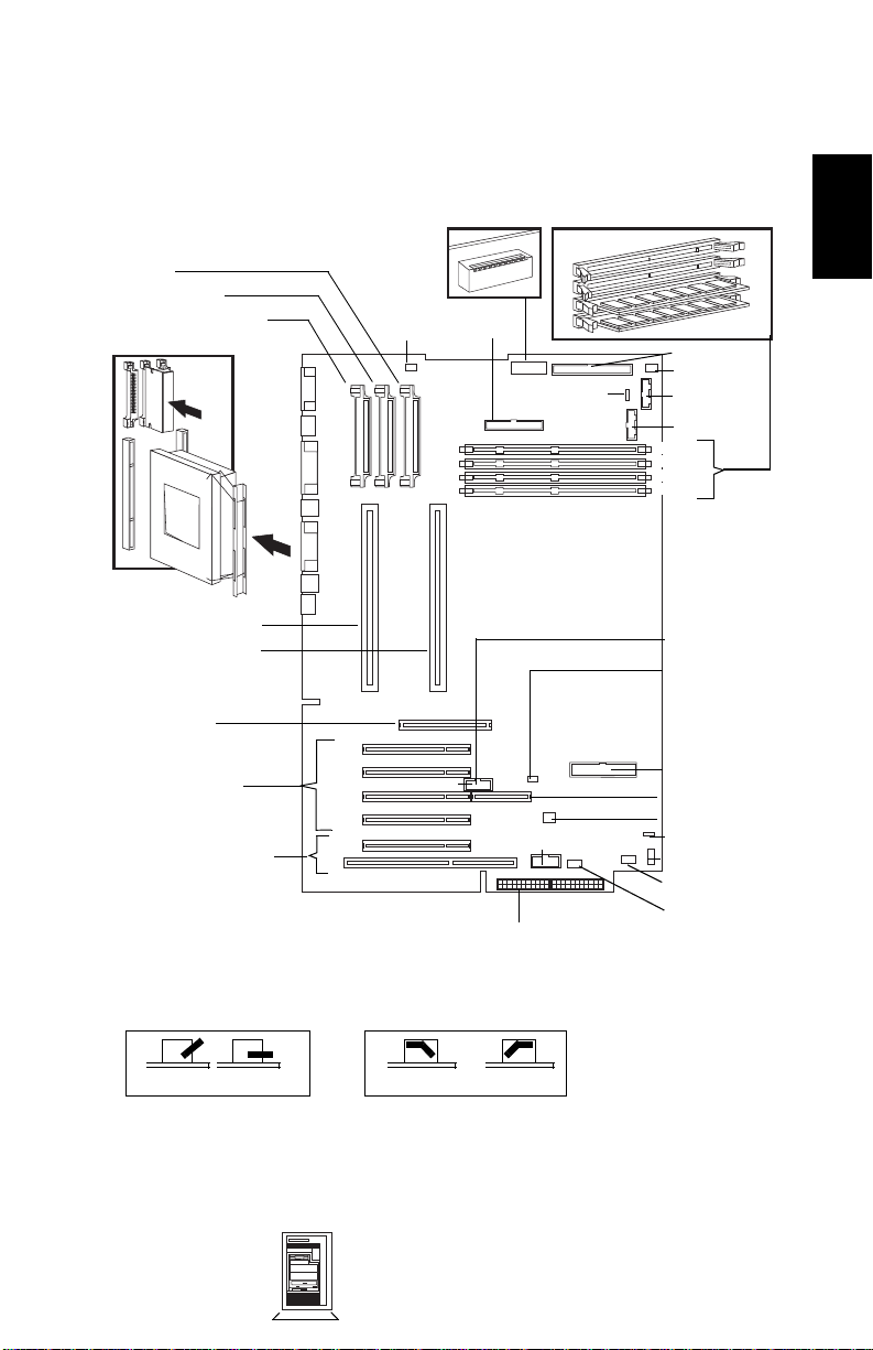
System Board, BIOS and Memory
1
Switches
VRM 3
VRM 2
VRM 1
Processor Fan
BOOT PROC [1]
FDD
External Battery
DUAL PROC [2]
Memory Modules
16-bit SCSI
Disk Drive Fan
Status Panel
LCD Panel
Mem 4
Mem 3
Mem 2
Mem 1
2
Processor 1 Slot
Processor 2 Slot
AGP Slot
PCI 1
Four PCI Slots
Combo PCI/ISASlot
1. There are two types of system board switch boxes.
OFF = UP ON = DOWN
PCI 2
PCI 3
PCI 4
PCI 5
or
OFF = OPEN ON = CLOSE
Multimedia Panel
Power Supply
HP External Start
Wake On LAN
IDE 1
RAIDport
I/O Cards Fan
Internal speaker
Aux In Audio
CD In Audio
Mic In
Mini-Tower
PC Workstations
HP Kayak XU Series 04xx and HP Kayak XW
Series 04xx 2-7
Page 9
2
HP Kayak XU Series 04xx and HP Kayak XW Series 04xx
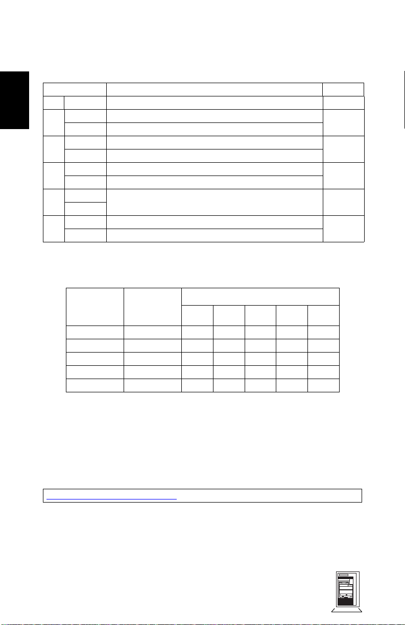
System Board Switches
Switch Function Default
1-5 — Processor frequency, see following table —
6OFF
7 OFF Enables User and Administrator passwords
8 OFF Disables power on using keyboard
9 OFF Reserved
10 OFF Normal operation
1. Refer to the diagrams on the previous page to determine their ON/OFF position on the system
2. Refer to “Recovery Boot Active Procedure” in Appendix B for the detailed recovery procedure.
1
Retain configuration in EEPROM, normal position
ON Clears EEPROM
ON Clears User and Administrator passwords
ON Enables keyboard power on
ON
ON Recovery boot active (force BIOS flashing)
board switch box.
OFF
OFF
ON
ON
2
OFF
Processor
Frequency
400 MHz 100 MHz
450 MHz 100 MHz
500 MHz 100 MHz
550 MHz 100 MHz
600 MHz 100 MHz
1. PCI Bus Frequency is 33 MHz
ISA Bus Frequency is 8.25 MHz
1
Local Bus
(FSB)
Frequency
12345
OFF OFF ON OFF OFF
OFF OFF ON OFF ON
OFF OFF ON ON OFF
OFF OFF ON ON ON
OFF ON OFF OFF OFF
Switch
Setup and BIOS History
For the latest BIOS, the flasher utility program, and the BIOS history refer to the
HP World Wide Web site. The BIOS is in the form HO11xxx.FUL, where xx is the
version number.
http://www.hp.com/go/kayaksupport
Installing a Dual Processor / Replacing a Processor
HP Kayak XU Series 04xx PC Workstations are supplied with either a
Pentium
2-8 HP Kayak XU Series 04xx and HP Kayak
XW Series 04xx
®
II Xeon or Pentium III Xeon™ processor.
Mini-Tower
PC Workstations
Page 10
HP Kayak XU Series 04xx and HP Kayak XW Series 04xx
A single Xeon processor must always be accompanied with two Voltage
Regulator Modules (VRM) inserted in the VRM sockets 1 and 2 (refer to the
diagram on page 7 for the VRM sockets position on the system board).
Single processor models can be upgraded to dual processor systems by
installing the second processor accessory in the vacant slot.
The second processor must be a Xeon processor of the same type, speed and
level-2 cache memory capacity as the first. It is installed by gently inserting the
processor into the vacant processor connector slot (labeled DUAL PROC [2])
until it clicks into place. Insert the VRM1 that was supplied with the second
processor into the vacant third VRM socket. The following table explains how
to perform supported processor upgrades.
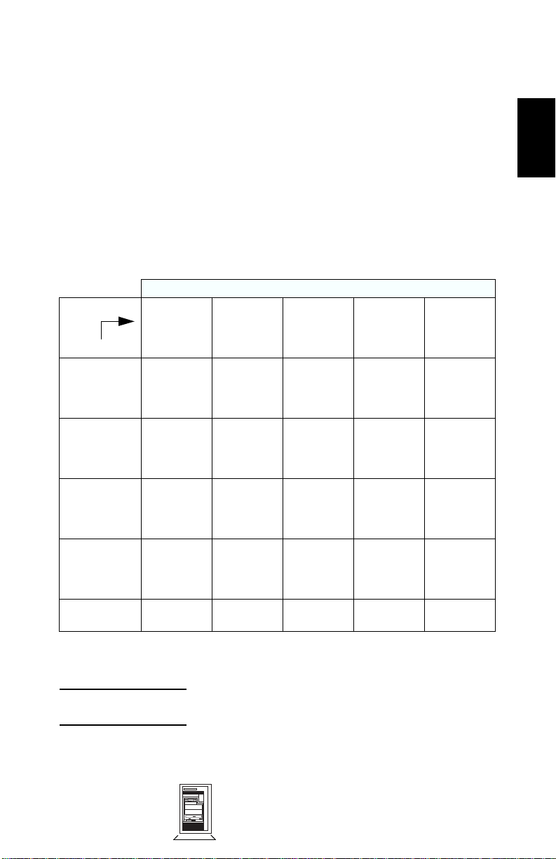
Dual Processor Upgrade
Upgrade
to
1 X 400 MHz
(D6740A)
1 X 450 MHz
(D6741A)
1 x 450 MHz
(D6939A)
1 X 500 MHz
(D7513A)
1 X 550 MHz
(D7514A)
1. Insert VRM that was supplied with the second processor into the VRM socket 3.
2. Supplied processor must be removed.
2 X
400 MHz
(D6740A)
nd
Add 2
1
D6740A
.
N/A Add 2
N/A N/A Add 2
N/A N/A N/A Add 2
N/A N/A N/A N/A Add 2
2 X
450 MHz
(D6741A)
Remove
D6740A2.
Add two
D6741A.
nd
1
D6741A
.
2 X
450 MHz
(D6939A)
Remove
2
D6740A
Add two
D6741A.
Remove
D6741A 2.
Add two
D6939A.
nd
1
D6939A
.
.
2 X
500 MHz
(D7513A)
Remove
D6740A
Add two
D7513A.
Remove
D6741A
Add two
D7513A.
Remove
D6939A2.
Add two
D7513A.
nd
D7513A
2
.
2
.
1
.
2 X
550 MHz
(D7514A)
Remove
2
D6740A
Add two
D7514A.
Remove
2
D6741A
Add two
D7514A.
Remove
2
D6939A
Add two
D7514A.
Remove
D7513A2.
Add two
D7514A.
nd
1
D7514A
.
.
.
.
2
NOTE: After installation of a second processor, the operating
system must be reinstalled.
1. Each VRM is specific to the processor with which it was supplied, and should only be used
with that processor.
Mini-Tower
PC Workstations
HP Kayak XU Series 04xx and HP Kayak XW
Series 04xx 2-9
Page 11

2
HP Kayak XU Series 04xx and HP Kayak XW Series 04xx
Cache Memory
512 KB or 1 MB of level-two cache memory is integrated in the Pentium II or
Pentium III Xeon processor package.
Main Memory
The PC Workstation has four DIMM slots on the system board for installing
main memory; slots Mem 1, Mem 2, Mem 3 and Mem 4. Models are supplied
with 128 MB of unbuffered main memory. If additional memory is required, up
to 1 GB of unbuffered memory may be installed. Memory upgrades are available
in single 64 MB, 128 MB or 256 MB unbuffered ECC SDRAM modules. Or,
alternatively, replace the existing unbuffered memory modules and install
Registered ECC SDRAM memory modules. Up to 2 GB of Registered memory
modules may be installed.
A serial EEPROM on each DIMM contains data on the memory speed. This
information is read at each power on, and access time settings are set
accordingly.
NOTE: Registered ECC SDRAM memory modules are not
compatible with unbuffered ECC SDRAM modules.
Therefore, memory can be upgraded to a maximum of
2 GB using only multiples of 512 MB Registered ECC
SDRAM modules (4 x 512 MB).
Video Memory on Kayak XU Series 04xx
The graphics controller installed on the PC Workstation could be either a
Matrox Productiva G100-Quad, a Matrox Millennium G200, an AccelGalaxy AGP
or an ELSA GLoria Synergy+™.
The Matrox Productiva G100-Quad graphics card can support a multi-monitor
environment allowing for a custom-configured display solution of up to four
monitors at a time with a total of 16 MB of video memory (4 MB per monitor).
There are three possible configurations: horizontally, vertically, or in a square.
The Matrox Millennium G200 has a 8 MB of SGRAM memory already supplied
on the graphics controller board. Memory may be upgraded to a maximum of 16
MB by installing a 8 MB SGRAM memory module onto the board.
The AccelGalaxy AGP Graphics card has 31 MB of video memory already
supplied on the graphics controller board, which cannot be further upgraded.
This card is supported only on the Windows NT operating system. Drivers do
not exist for Windows 95 nor Windows 98 operating systems.
2-10 HP Kayak XU Series 04xx and HP Kayak
XW Series 04xx
Mini-Tower
PC Workstations
Page 12

HP Kayak XU Series 04xx and HP Kayak XW Series 04xx
The ELSA GLoria Synergy+ includes 4 MB of installed SGRAM memory on the
video board. Added to this, there is a preinstalled 4 MB SO_DIMM (SGRAM)
memory module, giving a total of 8 MB, which cannot be further upgraded. No
switch or jumper settings are need to be changed (all jumpers should be left in
the positions in which they were set by the manufacturer).
HP VISUALIZE fx6 Hardware Accelerator
The HP Kayak XW Series 0480 contains an HP VISUALIZE fx6 graphics
hardware accelerator. There is a total of 18 MB of installed Synchronous
Graphics RAM (SGRAM) frame buffer on the graphics controller board.
HP VISUALIZE fx6 Texture Mapping Module
An additional 32 MB of Synchronous Dynamic RAM (SDRAM) texture memory
can be added by installing the texture mapping module accessory (D6795A) for
the HP VISUALIZE fx6 Graphics Accelerator.
2
For instructions on how to install the texture memory module, refer to the HP
VISUALIZE fx6 Texture Module Installation Guide which is supplied with the
accessory.
Mini-Tower
PC Workstations
HP Kayak XU Series 04xx and HP Kayak XW
Series 04xx 2-11
Page 13

2
HP Kayak XU Series 04xx and HP Kayak XW Series 04xx
NOTE: The texture module is automatically detected by the HP
VISUALIZE fx6 driver. The latest drivers may be
obtained from the HP World Wide Web site:
http://www.hp.com/go/kayaksupport
HP VISUALIZE fx4+ Hardware Accelerator
The HP Kayak XW Series 0475 contains an HP VISUALIZE fx4+ graphics
hardware accelerator. There is a total of 18 MB of installed Synchronous
Graphics RAM (SGRAM) frame buffer on the graphics controller board.
HP VISUALIZE fx4+ Texture Mapping Module
An additional 16 MB of Synchronous Dynamic RAM (SDRAM) texture memory
can be added by installing the texture mapping module accessory (D5511B) for
the HP VISUALIZE fx4+ Graphics Accelerator.
NOTE: The texture module is automatically detected by the HP
VISUALIZE fx4+ driver. The latest drivers may be
obtained from the HP World Wide Web site:
http://www.hp.com/go/kayaksupport
2-12 HP Kayak XU Series 04xx and HP Kayak
XW Series 04xx
Mini-Tower
PC Workstations
Page 14

HP Kayak XU Series 04xx and HP Kayak XW Series 04xx
Part Numbers
20b
20a
19
15
1g
5
4
1d
1e
1j
21
3b
1c
2a
2b
2c
1a
2
1
6
8
7
8
3a
1 i
9
2
18
17
Mini-Tower
PC Workstations
1h
16
13
14
22
12
HP Kayak XU Series 04xx and HP Kayak XW
1b
10
11
1f
Series 04xx 2-13
Page 15

2
HP Kayak XU Series 04xx and HP Kayak XW Series 04xx
Parts List
Item Description Repl.
1 Box assembly:
a Cover lock assembly
b Multimedia control panel (metal)
c Hard disk drive front tray (5.25-inch)
d Hard disk drive fan
e Processor airflow guide with fan
f I/O assembly guide with fan
g Internal speaker
h Base bezel kit
i LCD status panel kit
j Processor Cage for Slot 2
Not shown:
Bumper foot
Plastic clip guide for 8-bit SCSI cable
2 Cover assembly:
a Filler panel 3.5-inch
b Filler panel 5.25-inch
c Multimedia bezel
3 Logos:
a HP Kayak XU PC Workstation
b HP (cover pewter grey)
4 UW-SCSI Hard disk drive (standard)
a 4.5 GB, 10k rpm
b 9.1 GB, 10k rpm (Low Profile)
5 Power supply unit 0950-2891 —
6 Flexible disk drive (bezel-less) D2035-60191 —
7 CD-ROM drives
a32✕ IDE (standard) audio-less
b Sony 4/2/24X CD-RW
8 Rail kit (3.5-inch and 5.25-inch) 5063-7922 —
9 Internal IDE cable
10 CD-ROM to audio cable 5182-1857 —
11 Wake On LAN (WOL) cable 5183-2769 —
12 Headset (supported only on models
shipped before December, 1998)
13 HP 10/100 BT SCSI/PCI LAN Board 5064-6016 D6331-69301
1
3
(for CD-ROM) 5183-2713 —
Part Number
5064-6010
5062-5590
5064-6706
5064-6715
5064-6054
5064-6013
5064-6714
5063-6703
5064-6756
5064-6097
5064-6026
5042-2479
5042-3050
5064-3379
5042-1405
5042-1178
5042-1873
5042-3021
5042-3030
2
:
D6450-63001
D6451-63001
D4384-63001
D4398-60021
5064-2673 —
Exchange
Part Number
—
—
—
—
—
—
—
—
—
—
—
—
—
—
—
—
—
—
—
D6450-69001
D6451-69001
D4384-69001
D4398-69001
2-14 HP Kayak XU Series 04xx and HP Kayak
XW Series 04xx
Mini-Tower
PC Workstations
Page 16

HP Kayak XU Series 04xx and HP Kayak XW Series 04xx
Parts List
Item Description Repl.
14 Video boards:
a Elsa GLoria Synergy AGP (8 MB)
b Not shown on previous page:
a Matrox Productiva G100 Quad
Cable kit for G100 Quad
(contains 2 Y-cables)
b Matrox Millennium G200 (8 MB)
c AccelGalaxy AGP (31 MB)
HP VISUALIZE Video boards are shown
on pages 2-11 and 2-12
a HP VISUALIZE fx6
Texture module for VISUALIZE fx6
b HP VISUALIZE fx4+
Texture module for VISUALIZE fx4+
c Terminator
15 2-button mouse with scrolling wheel
Not shown:
HP 3-button mouse (only shipped with
models with the AccelGalaxy video
board)
16 CPU holder 5042-1162 —
17 System board See system board parts list
18 Processor terminator with plastic handle 5064-6007 —
19 Flexible disk cable 5183-0746 —
20 SCSI cables
a) 16-bit SCSI
b) 8-bit SCSI
21 Processor and terminator metal handle 5064-6716 —
22 FastRAID2 (Adaptec ARO2) card with
SIMM 16 MB memory
Not
Enhanced keyboard (US and European) C4734-60301 —
Shown
Power cable (European 220V) 8120-1689 —
Internal External Start LAN cable 5183-6090 —
I/O blank panel 45935-00004 —
Screw mach 6 x 32 2680-0311 —
Screws for Slot 2 (four spare screws
provided to be used near the I/O fan)
External Battery 1420-0552
4
Part Number
5064-6732
5064-7427
5183-9475
5064-7478
5064-7457
5064-3657
5064-3655
5064-3355
—
A4554-40001
C4736-60101
C4728-60101
5183-6019
5183-2179
5064-3668 D6690-69001
Not set up —
D6478-69501
D7980-69501
D5685-69501
D6728-69501
D6796-69501
D6795-69501
D6799-69502
D5511-69502
—
—
—
—
—
Exchange
Part Number
2
Mini-Tower
PC Workstations
HP Kayak XU Series 04xx and HP Kayak XW
Series 04xx 2-15
Page 17

2
HP Kayak XU Series 04xx and HP Kayak XW Series 04xx
1. Support plastic holder must be removed before installing the internal speaker.
2. For optional disk drive information, refer to the Accessory Service Handbook.
3. This is a specific IDE cable with the master connector on one end and the slave connector in
the middle of the IDE cable.
4. Refer to the diagram on page 2-11. Required when the texture module is not
installed. The terminator can be used on both the HP VISUALIZE fx6 and HP
VISUALIZE fx4+ video boards.
System Board Parts List
Description Repl.
System board:
1
Processors
Intel Pentium II Xeon 400 MHz, 512 KB cache D6740-63001 D6740-69001
Intel Pentium II Xeon 450 MHz, 512 KB cache D6741-63001 D6741-69001
Intel Pentium III Xeon 500 MHz, 512 KB cache D7513-63001 —
Intel Pentium III Xeon 550 MHz, 512 KB cache D7514-63001 —
Intel Pentium II Xeon 450 MHz, 1 MB cache D6121-63001 D6121-69001
Intel Pentium III Xeon 500 MHz, 1 MB cache D7110-63001 D7110-69001
Voltage regulator module (VRM) 0950-3389 —
Main memory modules 100 MHz):
1 x 32 MB unbuffered ECC SDRAM
1 x 64 MB unbuffered ECC SDRAM
1 ✕ 128 MB unbuffered ECC SDRAM
1 ✕ 256 MB unbuffered ECC SDRAM
1 ✕ 512 MB main memory Registered ECC
1. Heat-sink is integrated in the Pentium II processor package. Part provided with metal handler.
Remove this metal handler from the failed processor.
2. Registered and unbuffered memory modules cannot be mixed.
:
Part Number
D6340-60001 D6340-69001
D6521-63001
D6522-69001
D6523-63001
D6743-63001
2
D6742-63001
Exchange
Part Number
D6521-69001
D6522-69001
D6523-69001
D6743-69001
D6742-69001
Manuals and Documentation
User’s Guide D6339-90001 and
electronic file
Familiarization Guide electronic file -
Technical Reference Manual
D6339-90901
electronic file only
Software
ConfigTailor CD-ROM 5011-6631 —
2-16 HP Kayak XU Series 04xx and HP Kayak
XW Series 04xx
Mini-Tower
PC Workstations
Page 18

A
Beep, POST, and Error Codes
Beep Codes
If an error occurs during the POST, which prevents the PC Workstation from
starting, and before the display device has been initialized, a series of beep
codes are issued. Beep codes indicate that a fatal error has occurred and can be
reported one after another if there is more than one detected error. In this case,
the first detected error is the most important.
These codes are useful for identifying the error when the system is unable to
display the error message.
A
Beep, POST, and Error Codes A-1
Page 19

A
Beep Codes for the HP Kayak XU800
Number
of
Beeps
1 The memory refresh
2 Parity error in the base
3 Memory error.
4 Clock error. • Check that the system board is correctly
5 Processor test error. Check that:
6 Input/Output (I/O) error. • Keyboard is connected.
7 The processor on the
8 The system video card is
Description Action to Take...
Check that:
circuitry is faulty.
memory (the first 64 KB
block) of memory.
system board generated
an error.
either missing or faulty.
• Memory is installed correctly.
• Correct memory modules are being used.
If the error still occurs, replace the memory.
cabled (power cables, processor and
terminator).
If the error still occurs, replace the system
board.
• Processor is correctly installed.
• Termination card installed in processor
slot 2 in a single processor system.
If the error still occurs, replace:
1Processor.
2 system board.
• PCI card is installed correctly.
• Termination card installed in processor
slot 2 in a single processor system.
• There is an installed processor(s).
• Processor(s) is correctly installed in the
processor slot(s).
• Two installed processors have the same
cache size (256 k).
• Termination card is installed in processor
slot 2 in a single processor system.
• VRM is installed in the VRM socket in a
dual processor system.
If the error still occurs, replace the system
board.
This is not a fatal error. Check that the video
card is correctly installed and cabled. If
missing, install the video card. If the error
still occurs, replace it with a known working
video card.
A-2 Beep, POST, and Error Codes
Page 20

A
Number
of
Beeps
9 The BIOS Checksum
10 The CMOS RAM has
11 The cache memory test
Description Action to Take...
value does not match the
value encoded in the
BIOS.
failed.
failed.
Perform the following actions in this order:
1Press F2 to enter the Setup program,
then F9 to load the default BIOS settings.
2 Clear the CMOS.
3 Flash the BIOS.
If the error still occurs, replace the system
board.
Perform the following actions in this order:
1Press F2 to enter the Setup program,
then F9 to load the default BIOS settings.
2 Clear the CMOS.
3 Flash the BIOS.
If the error still occurs, replace the system
board.
Replace the processor(s).
Beep, POST, and Error Codes A-3
Page 21

A
Beep Codes for the HP Kayak XM600
Beep
Pattern
— - - - - - - -
— - - - — —
— - - - — - - -
— - - - - - - —
— - - - - - - - —
— - - - - - - - - - -
— - - - - — —
- - — - - - - -
- - - - - - - —
— - -
1. Non-HP memory modules are not supported. Only HP memory modules should be used.
Beep
Code
1-2-2-3 16h
1-3-1-1 20h
1-3-1-3 22h
1-3-3-1 28h
1-3-4-1 2Ch
1-3-4-3 2Eh
1-4-1-1 30h
2-1-2-3 46h
2-2-3-1 58h
1-2 98h
Numeric
Code
Description Recommended
BIOS ROM
check-sum
failure
DRAM refresh
test failure1
8042
Keyboard
controller test
failure
Initialization
of RDRAM
has failed.
RAM failure
on address
1
....
line
RAM failure
on data bits
....of low byte
of memory
bus1
RAM failure
on data bits
....of high byte
of memory
bus1
ROM
copyright
notice check
failure
Unexpected
interrupts test
failure
Video
configuration
failure or
option ROMs
check-sum
failure
Inform HP support/HP reseller
that system board is defective.
Check the memory is correctly
installed. If the error still occurs,
replace the module.
Inform HP support/HP reseller
that system board is defective.
Verify that memory or continuity
modules are installed.
Check the memory is correctly
installed. If the error still occurs,
replace the module.
Check the memory is correctly
installed. If the error still occurs,
replace the module.
Check the memory is correctly
installed. If the error still occurs,
replace the module.
Inform HP support/HP reseller
that system board is defective.
Inform HP support/HP reseller
that system board is defective.
This can be caused by problems
with the ROM on integrated
video, an add-on video board or
the ROM on a SCSI card.
Inform reseller for the affected
component.
Action
A-4 Beep, POST, and Error Codes
Page 22

POST and Error Codes
Beep Codes for Previous Models
The following beep codes are for all models before the HP Kayak XU800 and
XM600 PC Workstations.
A
Beep Pattern Beep
— - - - - - - - 1-2-2-3 16h BIOS ROM check-sum failure
— - - - — — 1-3-1-1 20h DRAM refresh test failure
— - - - — - - - 1-3-1-3 22h 8742 Keyboard controller test failure
— - - - - - - - — 1-3-4-1 2Ch RAM failure on address line xxxx
— - - - - - - - - - - 1-3-4-3 2Eh RAM failure on data bits xxxx1 of low
- - — - - - - - 2-1-2-3 46h ROM copyright notice check failure
- - - - - - - — 2-2-3-1 58h Unexpected interrupts test failure
— - - 1-2 98h Video configuration failure or option
- 1 B4h /
- - - - - - - - - - - - - - - 4-2-4-4 Crisis recovery flash error
1. If the BIOS detects error 2C or 2E (base 512K RAM error), it displays an additional wordbitmap (xxxx) indicating the address line or bits that failed. For example, “2C 0002” means
address line 1 (bit one set) has failed. “2E 1020” means data bits 12 and 5 (bits 12 and 5 set)
have failed in the lower 16 bits.
2. For more information, refer to Appendix B.
Code
1-3-3-1 28h Autosize DRAM
1-4-4-1 30h RAM failure on data bits of high byte of
Numeric
Code
F4h
Description
memory bus
byte of memory bus
ROMs check-sum failure
This does not indicate an error. There is
one short beep before system startup.
2
1
POST and Error Codes
A list of all POST (Power-On Self-Test) and error codes are available through
electronic files from the Support Center.
If you wish to view the POST details, press the key when the Kayak logo is
being displayed at power on, and the checkpoint code of the test currently in
progress will appear in the upper right corner of the screen. When POST is
completed, the HP Summary Screen will appear.
Beep, POST, and Error Codes A-5
Page 23

A
POST and Error Codes
Notes: ______________________________________________________________
____________________________________________________________________
____________________________________________________________________
____________________________________________________________________
____________________________________________________________________
____________________________________________________________________
____________________________________________________________________
____________________________________________________________________
____________________________________________________________________
____________________________________________________________________
____________________________________________________________________
____________________________________________________________________
____________________________________________________________________
____________________________________________________________________
A-6 Beep, POST, and Error Codes
Page 24

B
Recovery Boot Active Procedures
HP Kayak XU800 PC Workstation BIOS Recovery
NOTE: The following BIOS recovery (Crisis Mode) is for the HP
Kayak XU800 PC Workstation models only.
If for some reason the BIOS is corrupted and the standard flash cannot be used,
use the BIOS Recovery Mode (exceptional BIOS recovery operation) to restore
the BIOS.
The following recovery operation is also documented in the flash.txt file which
is supplied with the downloaded BIOS files.
To restore the BIOS:
1 Copy the BIOS files on to the floppy disk.
2 Rename the file AI11xx.rom to amiboot.rom.
3 Shut down the PC Workstation.
4 Power off the PC Workstation and remove the power cord and cables.
5 Remove the cover.
6 Set switch 1 to the DOWN position.
7 Insert the floppy disk into the floppy disk drive.
8 Reconnect the power cord and switch on the PC Workstation.
9 The PC Workstation boots from the floppy disk, then flashes the BIOS.
However, it should be noted that during the flash process, the screen remains
blank. MaxiLife will display a message on the LCD panel “RECOVERY
MODE”.
10 The recovery process is finished when there are four beeps.
11 Power off the PC Workstation. Remove the floppy disk from the drive.
Remove the power cord.
12 Set switch 1 back to the UP position.
13 Replace the cover, reconnect the power cord, then reboot the PC
Workstation.
B
Recovery Boot Active Procedures B-1
Page 25

HP Kayak XM600 PC Workstation Desktop and Minitower BIOS Recovery
B
NOTE: The following BIOS recovery (Crisis Mode) is for the HP
Kayak XM600 Desktop and Minitower PC Workstations
only.
If for some reason the BIOS is corrupted and the standard flash cannot be used,
use the BIOS Recovery Mode (exceptional BIOS recovery operation) to restore
the BIOS. To do this:
1 Obtain a bootable DOS floppy disk.
2 Copy the BIOS files on to the floppy disk.
The latest system BIOS (standard flash operation) can be downloaded from
HP’s Support Web site at: http://www.hp.com/go/kayaksupport. Then select
HP Kayak XM600 PC Workstation.
Instructions on updating the BIOS are supplied with the downloaded BIOS
files and a BIOS flash utility (flash.txt).
3 Create (or edit) the file, AUTOEXEC.BAT This should contain a single line of
text: “phlash /c /mode=3 IC1105US.FUL”
(rename the BIOS filename with the one on the floppy disk).
4 Shut down the PC Workstation.
5 Power off the PC Workstation and remove the power cord.
6 Remove the cover.
7 Set switch 7 to the ON position.
8 Insert the floppy disk into the floppy disk drive.
9 Reconnect the power cord and switch on the PC Workstation.
10 The PC Workstation boots from the floppy disk, then flashes the BIOS.
However, it should be noted, that during the flash process, the screen
remains blank.
11 The recovery process is finished when there is one very long beep.
12 Power off the PC Workstation. Remove the floppy disk from the drive.
Remove the power cord.
13 Set switch 7 back to the OFF position.
14 Replace the cover, reconnect the power cord, then reboot the PC
Workstation.
B-2 Recovery Boot Active Procedures
Page 26

Force BIOS flash, Switch 9 (XA models) or 10 (XW and XA-s models) Down Position
WARNING: WARNING: For Kayak XU Series 03xx, XA-s Series
02xx and XA Series 05xx, a specific ‘Mini-Dos’
bootable disk has to be used. An image of this
‘Mini-Dos’ bootable floppy can be obtained from
the Alps/Info server (not available from the
external web site). If you do not have access to the
Alps/Info server, contact your escalation team.
If, for example, during a BIOS flash, the procedure is interrupted by a power
failure, and the system does not restart, then you can force a BIOS flash.
However, it should be noted that during the procedure, there is no image on the
screen, nor access to the keyboard or mouse (only “vital” devices that are
required to boot on the floppy device are initialized).
To force a BIOS flash, do the following steps:
1 Ensure that you have created a DOS-bootable diskette. This floppy diskette
contains all the recovery and system BIOS programming software
(phlash.exe, platform.bin and hb1xxxyy.Ful). Include the flash command in
the autoexec.bat, for example: phlash /mode=3 hb1xxxyy.Ful
2 Turn off the computer.
3 Set Switch 9 (XA models) or,
Set Switch 10 (XW, XU and XA-s models) to the DOWN position (=on).
4 Insert the DOS-bootable diskette (refer to the above warning).
5 Power on the computer.
6 During the recovery process, short beeps are emitted. The recovery process
is finished when there is a much longer beep (approximately around 1 to 2
minutes).
7 Power off the computer. Press the power ON/OFF button (for about 5
seconds), until the ON/OFF light switches off. Set the switch 10 to the UP
position (=off).
B
Recovery Boot Active Procedures B-3
Page 27

B
Notes: ______________________________________________________________
____________________________________________________________________
____________________________________________________________________
____________________________________________________________________
____________________________________________________________________
____________________________________________________________________
____________________________________________________________________
____________________________________________________________________
____________________________________________________________________
____________________________________________________________________
____________________________________________________________________
____________________________________________________________________
____________________________________________________________________
____________________________________________________________________
B-4 Recovery Boot Active Procedures
 Loading...