

Page 1
Familiarization Guide
HP Kayak XU Series 0441
This guide is for experienced technicians who have already
completed the HP Kayak PC family training course. It assumes that
the reader is already familiar with the different HP Kayak models.
This document is a self-paced familiarization guide designed to train
you to repair the PC. It contains information specific only to the repair
of the HP Kayak XU Series 0441 PC Workstation.
For information on the installation of accessories, refer to the paper
User’s Guide and the online documents that are supplied with the PC.
To access the HP World-Wide Web support site:
http://www.hp.com/go/kayaksupport
PC Workstation
Page 2

Notice
The information contained in this document is subject to change without notice.
Hewlett-Packard makes no warranty of any kind with regard to this material,
including, but not limited to, the implied warranties of merchantability and
fitness for a particular purpose.
Hewlett-Packard shall not be liable for errors contained herein or for incidental
or consequential damages in connection with the furnishing, performance, or use
of this material.
Hewlett-Packard assumes no responsibility for the use or reliability of its
software on equipment that is not furnished by Hewlett-Packard.
This document contains proprietary information that is protected by copyright.
All rights are reserved. No part of this document may be photocopied,
reproduced, or translated to another language without the prior written consent
of Hewlett-Packard Company.
®
Pentium
Xeon is a trademark of Intel Corporation.
Microsoft
Corporation.
Windows NT
is a registered trademark of Intel Corporation.
®
, Windows® and MS-DOS® are registered trademarks of the Microsoft
® is a registered trademark of Microsoft Corporation.
Hewlett-Packard France
38053 Grenoble Cedex 9
France
1998 Hewlett-Packard Company
Page 3

Contents
Notice. . . . . . . . . . . . . . . . . . . . . . . . . . . . . . . . . . . . . . . . . . . . . . . . . . . . 2
HP Kayak PC Workstation Overview. . . . . . . . . . . . . . . . . . . . . . . . . . 5
Identifying the Latest Kayak XU PC Workstation . . . . . . . . . . . . . . . 7
HP Kayak PC Workstation Package. . . . . . . . . . . . . . . . . . . . . . . . . . . 8
System Board Layout. . . . . . . . . . . . . . . . . . . . . . . . . . . . . . . . . . . . . . . 9
Removing and Replacing the Cover. . . . . . . . . . . . . . . . . . . . . . . . . . 10
Preparing to Remove the System Board . . . . . . . . . . . . . . . . . . . . . . 11
Removing and Installing a Processor . . . . . . . . . . . . . . . . . . . . . . . . 12
Removing and Replacing the Power Supply Unit . . . . . . . . . . . . . . 14
Removing and Replacing the Internal Speaker . . . . . . . . . . . . . . . . 15
Removing and Replacing the Base Bezels . . . . . . . . . . . . . . . . . . . . 16
Removing and Replacing the 8-bit SCSI Protection Clip . . . . . . . . 17
Connecting to the LAN/SCSI Combination Board . . . . . . . . . . . . . . 18
LAN/SCSI Combination Board . . . . . . . . . . . . . . . . . . . . . . . . . . . . . . 18
HP MaxiLife Utility. . . . . . . . . . . . . . . . . . . . . . . . . . . . . . . . . . . . . . . . 19
Error Messages . . . . . . . . . . . . . . . . . . . . . . . . . . . . . . . . . . . . . . . . . . 20
Running the MaxiLife Diagnostics Program. . . . . . . . . . . . . . . . . . . 23
Checking the System Configuration . . . . . . . . . . . . . . . . . . . . . . . . . 24
Checking the Display Screen . . . . . . . . . . . . . . . . . . . . . . . . . . . . . . . 25
Upgrading Main Memory Modules. . . . . . . . . . . . . . . . . . . . . . . . . . . 27
English 3
Page 4

Mixing Memory Modules . . . . . . . . . . . . . . . . . . . . . . . . . . . . . . . . . . 27
Installing 10krpm Hard Disk Drives on a Kayak XU . . . . . . . . . . . . 28
Flashing the Latest Version of the System BIOS . . . . . . . . . . . . . . . 29
Complete the Questionnaire
to Check Your Understanding. . . . . . . . . . . . . . . . . . . . . . . . . . . . . . . 30
Answers and Explanations . . . . . . . . . . . . . . . . . . . . . . . . . . . . . . . . . 32
Electrostatic Discharge Warning . . . . . . . . . . . . . . . . . . . . . . . . . . . . 35
4 English
Page 5

HP Kayak PC Workstation Overview
HP Kayak PC Workstation Overview
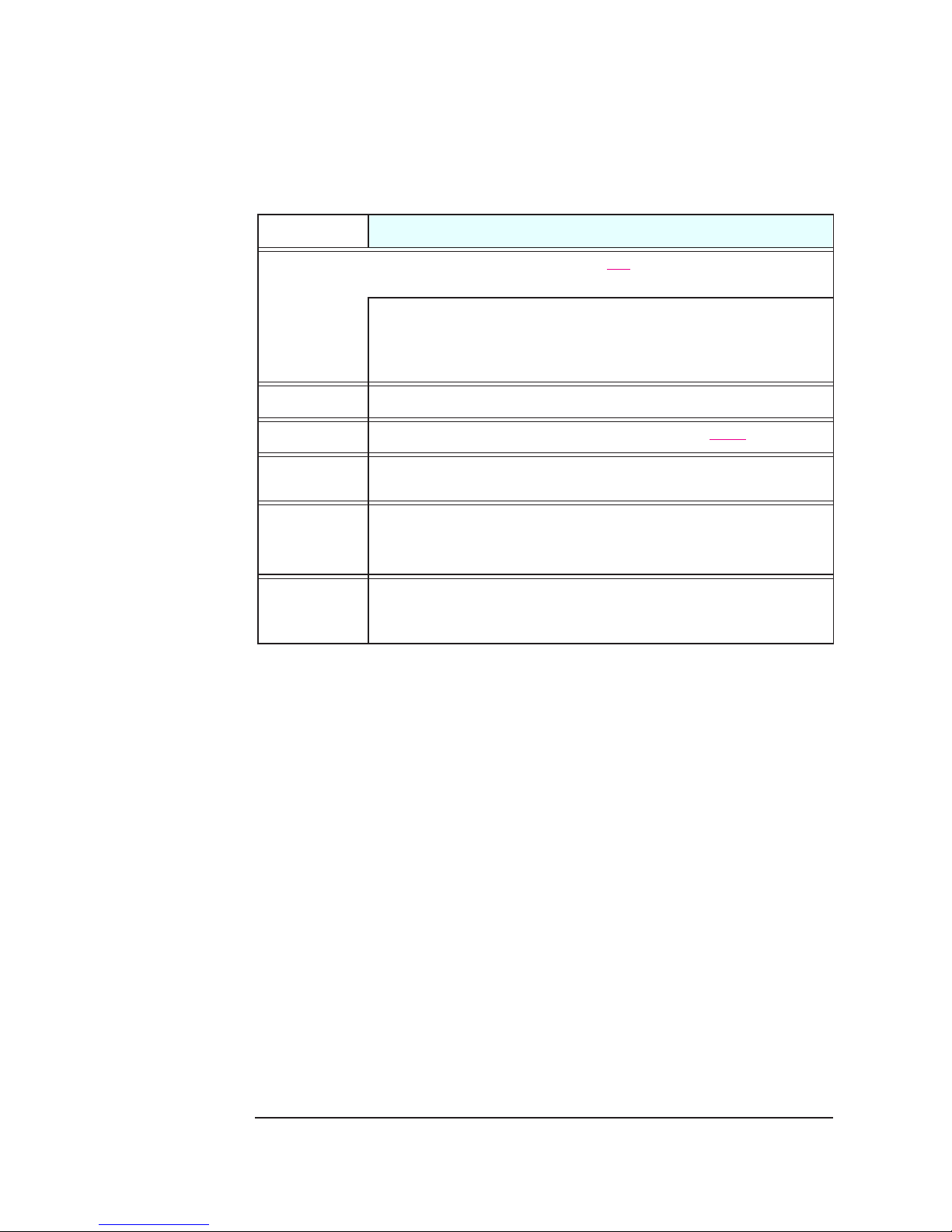
The following table provides an overview of the HP Kayak XU Series 0441
PC Workstation.
How to use the table:
underlining A new feature (compared with previous models is highlighted by underlining)
Component
Microprocessor
External
Processor Bus
(Front Side Bus)
Level 2 Cache
Bus
Operating
System
Main Memory
Mass Storage
Features
®
All models have: Intel Pentium
memory. Support for up to two Pentium II Xeon processors.
400, 450
Runs at the same speed as the Processor.
All models are preloaded with Windows NT 4.0.
Four DIMM sockets supporting:
512 MB Registered 100 MHz ECC SDRAM
64 MB, 128 MB or 256 MB unbuffered 100 MHz ECC SDRAM to a maximum of 1 GB.
4.5 GB or 9.1 GB Ultra-Wide SCSI Low Profile (LP)
Optional HP FastRAID 2
MHz: 100 MHz FSB.
Registered ECC SDRAM memory modules cannot be mixed with Unbuffered modules.
All models have 7 shelves: 5 front access (two 3½-inch, three 5¼-inch);
II Xeon™ processors with 512 KB or 1 MB cache
memory module to a maximum of 2 GB, or
2 internal (3½-inch).
nd
generation
SCSI
Connectors
Video
Controllers
Ultra-Wide 16-bit internal SCSI connector for both external and internal drives (up to
40 MB per second), plus two internal narrow SCSI connectors.
Subsystem with HP FastRAID Port.
All models are equipped with a ELSA GLoria Synergy AGP
There is 8 MB of installed SGRAM video memory which cannot be upgraded. This is
subject to change, refer to the HP World Wide Web site for up-to-date information.
graphics controller board.
5
Page 6
HP Kayak PC Workstation Overview
Component
Accessory
Board Slots
Communications
CD-ROM Drive
Audio
HP MaxiLife
Utility (available
on all models)
Power Supply
1.
WOL = Wake On LAN
Features
All models have 6 slots: 1 AGP, 4 PC
1
Support for WOL
compatible LAN boards.
I, 1 combination ISA/PCI.
I PCI slot (slot 4) used for the LAN/Ultra-Wide SCSI board with RPO capability.
1 AGP slot used for the Video Adapter.
1 RAID/PCI slot which is intended for the Adaptec
®
ARO-1130 PCI RAIDport™ adapter new generation (FastRAID2).
All models have 2 USB (A, B) connectors, 2 serial ports, 1 parallel port
Some models include either a 32X speed IDE CD-ROM, or a CD-RW
CD-ROM.
All models have an integrated 16-bit hi-fi audio processor
with music synthesizer and mixer
Hardware monitoring utility that monitors system components (for example: if you are
unable to get the system and display working properly). When an error is detected it is
displayed on the dedicated LCD located on the front panel.
Input voltage: 100-127, 200-240V ~
Input frequency: 45/66Hz
Maximum output power: 350W continuous
6
Page 7
Identifying the Latest Kayak XU PC Workstation
Identifying the Latest Kayak XU PC Workstation
How can I distinguish the difference between the latest HP Kayak
XU model Series 0441 and the previous HP Kayak XU models Series
0301 and Series 0303?
There are three simple and quick ways to identify the latest HP
Kayak XU model. First, the label on the side of the newer Kayak
XU indicating “Series 0441”. Secondly, the processor is an Intel
Pentium II Xeon, and finally the system package with
reinforced processor cage.
As well as the above-mentioned differences between the two HP Kayak XU
models, the Kayak XU Series 0441 model incorporates the new HP designed
system board based on the Intel
Registered memory modules.
®
440GX AGPset supporting up to 2 GB of
Component
Pentium II Xeon
Processor
Cache
Memory Support
PCI Slots
New Package
(8 cm higher than the
standard XU package)
Graphics Controller
The following table shows the comparison between the HP Kayak XU
models.
HP Kayak XU Series 0441
(Introduced August/ October ‘98)
Pentium II Xeon processor(s) with an operating
frequency of 400 MHz or 450 MHz on a 100 MHz
system bus.
Level 2 cache runs at the same speed as the CPU. Level 2 cache runs at half the speed of the CPU.
Up to 2 GB of SDRAM memory (using 4 x 512 MB of
Registered memory modules).
Maximum of five PCI slots. Maximum of four PCI slots.
Reinforced processor cage to hold in place the
Pentium II Xeon processor(s).
Elsa GLoria Synergy™ video controller board with
8 MB of installed memory, which cannot be upgraded.
(It should be noted that the video controller model may
change).
HP Kayak XU Series 0301 and Series 0303
(Introduced June/July ‘98)
Pentium II Slot 1 processor(s) with an operating
frequency of 350 MHz or 400 MHz on a 100 MHz
system bus.
Up to 1 GB of SDRAM memory (using 4 x 256 MB of
Registered memory modules).
Not required for this series.
®
Models are equipped with either a Matrox
AGP or a Matrox Millennium II G200 graphics controller.
There may also be some models equipped with an ELSA
GLoria Synergy video controller.
Millennium II
7
Page 8
HP Kayak PC Workstation Package
HP Kayak PC Workstation Package
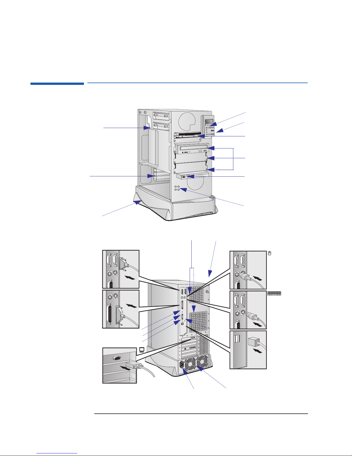
Front view
Rear View
2 internal mass storage
shelves: 3.5-inch wide.
Upper shelf: 1-inch high
Lower shelf: 1.6-inch high
Up to six accessory boards can be
installed:
• One AGP Slot
• Four 32-bit PCI Slots
• One combination slot PCI or ISA
Power Supply Unit
Serial ports A and B
Two Processor fans
HP MaxiLife LCD buttons
LCD Status panel
Two 3.5-inch wide shelf
(including the floppy disk drive)
Three 5.25-inch wide by
1.6-inch high front-access
shelves (including CD ROM drive)
Audio Front Panel
Four spare screws (these are to
be used to secure the system
board in place only).
Key lock
Mouse connector
Parallel port
Line Out jack
MIDI/joystick connector
Display connector
8
Line In jack
Keyboard connector
MIC-in
jack
Two USB connectors
Power connector Two Power supply fans
Page 9
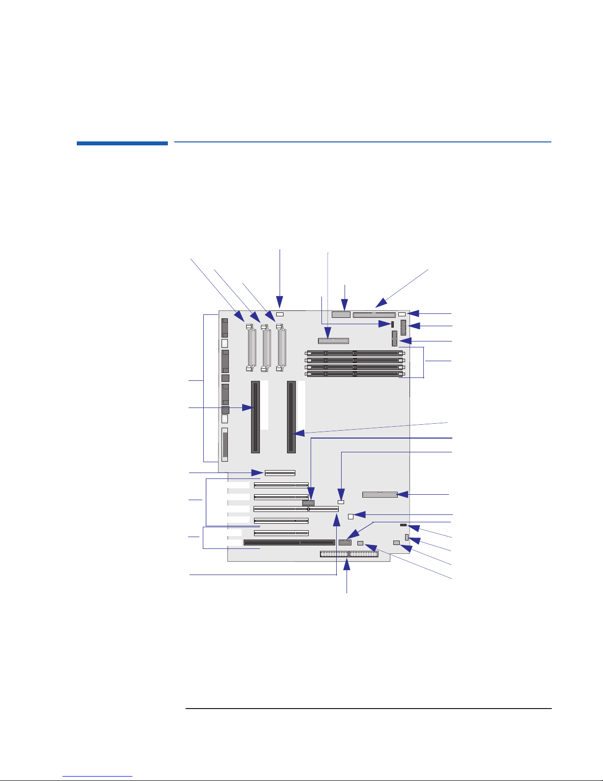
VRM 1 - J44
Rear Panel Connectors
System Board Layout
Processor Fan - J34
VRM 2 - J37
VRM3 - J32
BOOT PROC
External
Battery - J9
DUAL PROC
Hard Disk Drive
Connector - R320
System Board
Switches
Wide 16-bit SCSI
Connector - J15
Hard Disk Drive Fan - J4
Status Panel - J5
LCD Status Panel - J8
Mem 4 - X3
Mem 3 - X4
Mem 2 - X5
Mem 1 - X6
System Board Layout
Processor 1 Slot
One AGP Slot - J35
Four PCI Slots
One PCI/ISA
Combination Slot
RAIDport - J24
PCI 1 - J38
PCI 2 - J39
PCI 3 - J40
PCI 4 - J41
PCI 5 - J42
ISA - J46
Processor 2 Slot
HP External Start - R403
Wake On Lan - J20
IDE 1 Connector - J14
I/O Cards Fan - J16
Multimedia Panel - J17
Internal Speaker - J2
Aux In Audio - J3
CD In Audio - J6
Mic In - J12
Power Supply
Connector - J11
9
Page 10
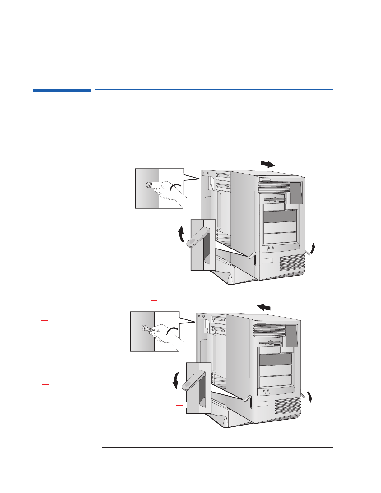
Removing and Replacing the Cover
Removing and Replacing the Cover
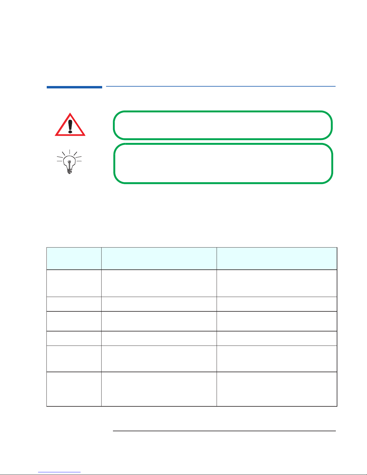
WARNING: For your safety, never remove the PC’s cover without first removing the
power cord from the power outlet, and any connection to a
telecommunication network. Always replace the cover before switching on
the PC again.
Removing the Cover
Switch off the display and computer.
Disconnect all power cords, LAN or
telecommunications cable and accessory
cables. If necessary, unlock the cover. The
lock and key for the cover are at the back
of the PC Workstation, just below the rear
panel connectors.
Lift the two latches on the front sides
of the computer upwards.
Grasp the cover on the sides at the
back of the computer and slide it forwards
and off the computer.
Replacing the Cover
Ensure that the two latches on
the front sides of the cover are lifted
up, and that the lock is unlocked. Slide
the cover onto the computer, making
sure that the two guides at the bottom
of the case slide into the two rails at
the base of the computer. Firmly slide
the cover backwards into position.
Lower the two latches on the
front sides of the cover.
If required, lock the cover using the
key. If required, lock the cover using the
key. Reconnect all power cords, LAN or
telecommunications cable and
accessory cables.
10
Page 11
Preparing to Remove the System Board
Preparing to Remove the System Board
Due to the fact that the Intel Pentium II Xeon processor weighs about 1 kg,
the system board can be damaged because of vibration if it is not securely
set in place.
The system board on the Kayak XU Series 0441 PC Workstation is secured to
the PC chassis by seven screws. These screws are longer than the standard
ones used on the PC Workstation and are not available as spare parts. If you
do lose or mislay any of these screws, there are four spare ones located on
the front of the chassis (underneath the audio front panel). These screws
are to be used uniquely to secure the system board.
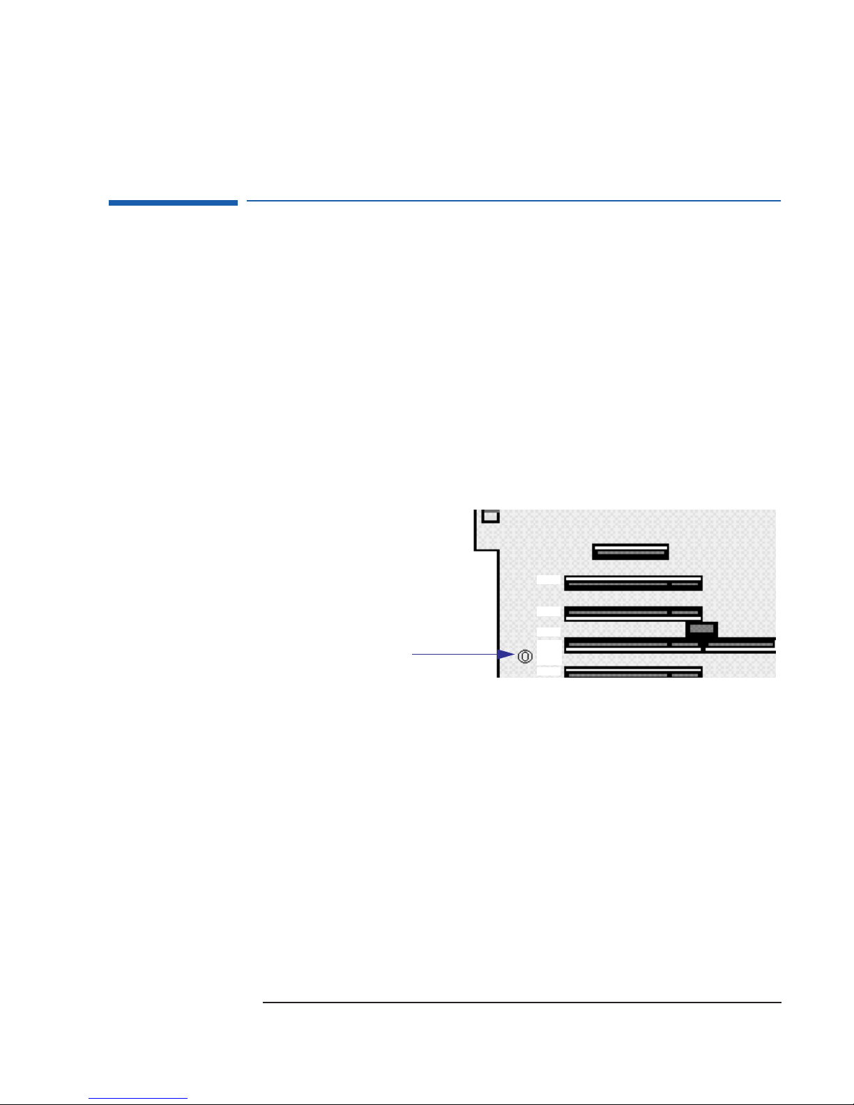
Before attempting to remove the system board, you will have to first
unscrew these screws. Six of them can be accessed from the outside of the
chassis, while the seventh screw is located near PCI Slot 3.
Screw located near PCI Slot 3
that needs to be removed before
removing the system board.
PCI 1
PCI 2
PCI 3
RAID
PORT
PCI 4
11
Page 12

Removing a
Processor
Remove the metal
retaining plate that
secures the processor(s),
by releasing the four (4)
self-retaining screws.
Remove the
processor from the socket
by gently pulling the
processor away from the
system board by the
processor’s handle.
Removing and Installing a Processor
Removing and Installing a Processor
To access the VRMs,
you will need to remove
the airflow guide. Press
the retaining buttons on
each side of the airflow
guide and lift it partly out
of the PC Workstation’s
case. Remove the fan
connection to the system
board and lift the airflow
guide completely out.
12
Page 13

Installing a
Single Processor
VRM 1
Removing and Installing a Processor
VRM 2
Insert the processor into the BOOT
processor socket until it clicks into
PROC
place. Do not
processor system in the DUAL PROC
processor socket.
install a processor for a single
Insert the VRMs into the VRM
sockets 1 and 2 (from left to right).
Replace the airflow guide and
reconnect the fan to the system board.
BOOT PROC
➍ Replace the metal retaining plate that
secures the processor(s) and tighten the
four self-retaining screw.
13
Page 14

Removing and Replacing the Power Supply Unit
Removing and Replacing the Power Supply Unit
Removing the
Power Supply Unit
Ensure that the computer’s
power cord is disconnected from
the computer.
Place the computer on its
side. Unscrew the four screws at
the bottom of the computer.
(a) Disconnect the power
cables from any connected mass
storage devices; (b) Unclip the
main power supply unit cable
(thick black cable located on the
right-hand side) from the
computer; (c) Then lay the cable
to the side to improve access to
the power supply.
➍ Disconnect the two power
supply cables (P1 and P1 Bis) on
the system board from the power
supply unit.
➎ (b)
(a)
➍
(b)
➎ (a)
(c)
➎ (a) Place your hand on the
power supply unit (you need to
slide your hand into the
computer to do this). Gently push
the power supply unit towards
the rear of the computer.
(b) Push the power cables down
while sliding out the power
supply unit, until they are clear
of the computer.
Replacing the Power Supply Unit
Slide the power supply unit back into the computer. Ensure that
the cables are flat and do not get trapped between the top of the
power supply unit and the bottom of the computer.
Reconnect the two power supply cables to the system board.
Connector P1 is inserted into the left-hand side and P1Bis into the
right-hand side of the J1 Power connector. Clip the main power
supply unit cable back into place. Reconnect the power supply
cables to the mass storage devices.
14
Place the computer on its side (if it is not already). Replace the
four screws at the bottom of the PC. Then return the computer to
its upright position.
➍ Reconnect the computer’s power cord to the computer.
Page 15

Removing and Replacing the Internal Speaker
Removing the Speaker
Ensure that the computer’s
power cord is disconnected from
the computer.
Place the computer on its
side. Unscrew the four screws at
the bottom of the computer.
Return the computer to its
upright position.
To improve access to the
internal speaker, disconnect the
power cables from any
connected mass storage
devices. Then unclip the main
power supply unit cable (thick
black cable located on the righthand side) from the computer.
From inside the computer,
gently slide out the power
supply unit towards the rear of
the computer until it stops.
Replacing the Speaker
Slide the power supply unit back into the
computer. Ensure that the cables are flat and do
not get trapped between the top of the power
supply unit and the bottom of the computer. Clip
the main power supply unit cable to the
computer. Reconnect the power cables to any
connected mass storage devices.
Removing and Replacing the Internal Speaker
➍ Push the internal speaker in the
direction of the system board.
Disconnect the internal speaker
cable from the system board.
The internal speaker is held in place by two
clips. Align the internal speaker up with the
bottom clip, then push it towards you until it
clicks in place. Connect the internal speaker cable
to the system board.
Two clips
that hold the
speaker in
place.
Place the computer on
its side. Replace the four
screws at the bottom of the
PC. Then return the computer
to its upright position.
➍ Reconnect the
computer’s power cord to the
computer.
15
Page 16

Removing the Base Bezels
Lay the computer on its side.
Removing and Replacing the Base Bezels
Removing and Replacing the Base Bezels
(a) On the side base bezel, push the
two tabs upwards, then pull the base bezel
towards you.
(b) Turn the computer on to its other
side, and repeat the steps mentioned
above to remove the second side base
bezel.
Return the computer to its upright position.
Push the two tabs on the front base bezel
outwards, then pull the base bezel towards you.
Replacing the Base Bezels
With the computer in its upright position,
line- up the two tabs and the two small plastic
locaters with their respective locations. Gently
insert the front base bezel until it clicks into
place.
(a)
Lay the computer on to its side.
(a) Line up the four plastic guide tabs on the
side base bezel with their respective locations.
(b) Place your hands on each end of the side
base bezel, then press it downwards until the four
plastic guide tabs clear the guide ridge. Push the
side base bezel forwards until it clicks into place.
➍ Turn the computer on its other side, and repeat the
steps mentioned in step
bezel.
to install the second side base
16
(b)
(a)
(b)
Page 17

Removing and Replacing the 8-bit SCSI Protection Clip
Removing the 8-bit SCSI Protection Clip
Refer to page 10 for instructions on how to remove and replace the cover.
Press the tab on the right-hand side of the 8-bit SCSI
protection clip and pull outwards at the same time.
Removing and Replacing the 8-bit SCSI Protection Clip
DO NOT PULL the 8-bit SCSI Protection clip
directly out. The clip be broken.
Replacing the 8-bit SCSI Protection Clip
Insert the clip in the hole on the left-hand side
Push inwards the tab on the right-hand side, while
at the same time inserting the clip in the hold.
Push the 8-bit SCSI protection
clip until it clicks into place.
17
Page 18

Connecting to the LAN/SCSI Combination Board
Connecting to the LAN/SCSI Combination Board
The HP Kayak Series 0441 PC Workstation contains a SCSI/LAN
10BT/100TX combination board which is installed in PCI Slot 4. This
combination board includes two connectors:
• Wake On LAN (WOL) which enables a host computer, using Magic Packet
technology, to remotely (over the network) power on computers (Remote
Power On) or wake them up (Remote Wake Up) from energy-saving Sleep
mode.
For these functions to work, the WOL cable must be connected
between the SCSI/LAN Combination board, located at the bottom righthand-side corner (J8) and the WOL connector on the system board (J20).
• External Start connector which enables LAN activity, the SCSI LED
activity on the front panel for SCSI hard disk drive accesses, and external
SCSI cable detection.
The external cable must be connected to the internal connector (J4) on
the bottom right-hand-side of SCSI/LAN combination board to the HP
External Start connector (R403) on the system board.
LAN/SCSI Combination Board
Three-pin connector to
connect the WOL cable to
the system board.
Thirteen-pin connector to
connect the external cable
to the system board.
Refer to page 9 to find out where the HP External Start
and WOL connectors are located on the system board.
NOTE Do not connect any devices to the Internal Narrow SCSI, and to the Internal
Wide SCSI at the same time. If you do, this results in a badly “terminated”
SCSI bus. In the HP Kayak XU and XW PC Workstations, only an Internal
Narrow SCSI cable is provided.
Internal Wide SCSI
connector (not used).
Internal Narrow SCSI
connector (used).
18
Page 19

HP MaxiLife Utility
HP MaxiLife Utility
HP MaxiLife is a hardware monitoring chip which is resident on the system
board. This chip receives data about the various system components via a
dedicated I
error state (for example, there is a CPU failure), it displays a warning with a
flashing LED and message on its LCD that specifies which component has
the problem.
Due to HP MaxiLife’s system independent design, even if there is a serious
component failure, it remains in operation and is able to indicate what the
problem is via the LCD.
For the HP MaxiLife to work correctly, the PC Workstation must always be
connected to a grounded outlet. This enables the PC Workstation’s hardware
monitoring chip to be active, even if the system has been powered off.
2
C bus. If it detects a potential error or that a component is in an
System info
Boot steps
Next Go
The following diagram shows where the LCD is located on the HP Kayak
XU Series 0441 PC Workstation.
Use this button to scroll
through the menu items
Use this button
to validate a
menu item
The following menus are available on the HP MaxiLife utility when pressing
the menu button:
• System Info. Obtains information from the BIOS and the system’s Serial
EEPROM from a previously successful boot. This information includes:
product name (HP Kayak XU) BIOS version, serial number, the number
of processors and speed, size of memory for each DIMM socket.
19
Page 20

Diags
Exit
Next Go
HP MaxiLife Utility
• Boot Steps. Shows the Power-On Self Test (POST) codes during the
system startup. The POST code is provided by the BIOS and is displayed
on the LCD panel as soon as it is available. If the system stops during the
startup, the last successful boot step POST code is displayed on the LCD.
Diagnostics. Runs a set of diagnostics assessing the system’s
components. Results of the tests are displayed on the LCD one after
another when the user presses the button.
Result of the diagnostics is: OK/FAIL.
Error Messages
When the PC is turned on (pressing the ON/OFF button), the system
initiates the normal startup sequence. A first diagnostic (called pre-boot
diagnostics) is run to check the presence of the processor, DIMM, VRM and
power supply.
MaxiLife does not purposely ‘freeze’ the system if an error is detected.
However, some critical hardware errors are fatal to the system and will
prevent the system from starting (for example, ‘Power’, ‘Board PLL’ are
serious malfunctions that will prevent the CPU to work correctly).
Errors that are not so critical (for example, ‘CPU Socket’ for missing
terminator, or ‘NO RAM’) are also detected by the POST and will abort its
own boot process after beeping. The ‘RAM type’ error is only detected by
POST with the same abort process.
Finally, while the PC is working, fan and temperature controls can be
reported (for example, a fan error when a cable is not connected). This type
of error disappears dynamically when the problem has been fixed (for
example, the fan cable has been reconnected).
If an error is detected, a screen appears on the LCD panel. The following
table shows the test sequence carried out, the type of error message, and
the action to take.The errors mentioned are standard error codes (they are
displayed without the need of pressing any key on the LCD status panel).
20
Page 21

Test Error Code Action to Take
HP MaxiLife Utility
1 When pressing one of the LCD status
panel buttons, nothing is displayed.
2 When the system is powered on, nothing is
LCD status panel
is blank
• Check that the two cables to the LCD status panel are properly
connected (refer to the system board layout for position).
• Check that the PC’s power cable is plugged in.
displayed.
Presence of a processor in the BOOT PROC [1]
processor slot. This is test is for a single
NO CPU 1 • Check that the processor is correctly installed in the BOOT
PROC [1] slot.
processor system only.
Presence of either CPU or Terminator in the
CPU SOCKET • Check CPUs and Terminator and VRM of installed processor.
processor slot.
Number of installed DIMMs NO RAM • Check that the memory module is correctly installed in the
memory socket.
Control of some voltages: VRMs, 12V POWER SUPPLY • Check the power supply connectors, VRM, CPU. In a single
processor system, check that the VRM is not plugged into the
terminator socket.
The error message could also show: Power CPU1 and Power
CPU2.
Test of the correct power signals to the CPU.
The power supply may be OK, whereas the VRM
is not.
POWER • Check that the VRM, processor and terminator are correctly
installed.
• Check that the VRM is not plugged on a socket with a
terminator (this could be the likely cause).
• Check or replace the VRM.
• Check the power supply unit connectors.
Presence of VRMs and their associated
processor.
Presence of a VRM in VRM socket 2. This test is
for both single and dual processor systems.
Check the system board clock generators (PLL). BOARD PLL • Check the power supply connector.
Compatibility of DIMMs. The BIOS checks that
the inserted DIMMs are both compatible with
one another, and compatible with the Front Side
Bus frequency.
POWER CPU • Check that the VRMs are correctly installed in their VRM
sockets.
POWER CPU 1 - Check VRMs sockets 1 and 2.
POWER CPU 2 - Check VRM socket 3.
POWER CACHE • Check that the VRM is correctly installed in VRM socket 2.
• Replace the system board (PLL clock generator).
RAM TYPE • Check the installed memory modules. This error occurs when
mixing incompatible memory modules, for example, when
installing a 66 MHz DIMM on a 350 MHz or higher system, or
when mixing Unbuffered and Registered memory modules.
21
Page 22

HP MaxiLife Utility
Test Error Code Action to Take
Availability of video controller. It is also checked
by the BIOS. If an error is detected, it is not a
fatal one and the BIOS will continue its
execution normally.
In order to detect whether the CPU is able to run
a given code, HP MaxiLife waits for a
synchronization event from the BIOS. Any failure
that prevents the execution of the firmware will
trigger an error.
The BIOS then executes the Power On Self Test
(POST) sequence. In this phase, HP MaxiLife
waits for any error messages that the BIOS may
issue.
During normal usage of the PC, HP MaxiLife is
always checking vital parameters of the system.
If an error should occur, a message would be
automatically displayed on the LCD panel.
1.
Special cases: Board PLL = System board needs replacing. CPU error = Reset or power off the system to recover.
NO VIDEO • Check that the video controller is correctly installed.
Note: No error is detected if a monitor is not connected to an
installed video controller.
BIOS • Flash the latest version of the system BIOS by using the system
recovery procedure. Set switch 10 to the down position.
• Check that the RAM is correctly installed.
• Check that the CPU is firmly inserted.
POST XXXX • If the screen is working, you can obtain the signification of the
error by typing “Enter” at the end of the POST. Or, you can
check the list of errors that are available on the HP World-Wide
Web support page.
TEMP IO SLOT • Check the connection of the corresponding component, which
could be: “Temp IO slot”, “Power errors, “Fan CPU”, “Board
PLL”, “Temp disk”, “Temp CPU”, “Fan disk”, “Fan IO slot”, “CPU
1
error”.
Special Cases 1 If a CPU is not installed correctly.
Either the “Power CPUx” or “CPU socket” or “BIOS” message may
appear. This will depend on which end of the CPU connector is not
correctly inserted.
2 If a VRM is installed and there is a terminator in the associated CPU
socket.
MaxiLife displays “Power” error message and the system does not start
3 Only one pre-boot error reported on the system.
Hidden errors will be revealed when the current error has been fixed.
4 If a “No Video Error” message is displayed, even though the video is
working correctly.
With some specific add-on boards (for example, 1540 from Adaptec
with SCSI BIOS), this error may appear while the system is fully working. To check if this is the case, remove all add-on boards from the basic system configuration.
22
Page 23

Running the MaxiLife Diagnostics Program
Running the MaxiLife Diagnostics Program
Can I run the HP MaxiLife Utility Diagnostics program when the
computer is powered off?
Yes, you can. However, the power cable must be connected to a
wall socket. The Diagnostics program will run low-level tests
on the memory, processor(s), VRM, power supply, video controller and the main clock generator on the system board
(Board PLL).
Even with the computer powered off (the LCD status panel will be blank),
HP MaxiLife is still running and monitoring the state of the LCD buttons. If,
one of the two buttons is pressed, the LCD status panel will display a second
menu. To run the diagnostics option, proceed as follows:
1 Press one of the LCD buttons, or to display the main screen.
2 Use the button to scroll through the menus until you reach the
Diags
option. Then press the button.
3 Use the button to select
Power on. The main power supply is
started, enabling the hardware monitoring chip to assess the status of the
computer’s components.
NOTE Although the main power supply has been started, the computer does not
continue to complete a normal boot.
4 Use the button to scroll through the
Diags option. The system
components are tested in sequence with the results being displayed on
the status panel. Press the Next button to move on to the following test.
If no errors are detected, you can exit the test session by pressing
the button. The main power supply will be turned off and the
LCD status screen will become blank.
If an error is detected, a short message will be displayed indicating
which component has a problem.
For example: DIMM found:0
This indicates that there are no memory modules detected.
NOTE The display of a warning with a flashing LED and message on the LCD status
panel are not available when the computer has been powered off.
23
Page 24

Checking the System Configuration
Checking the System Configuration
I need to check the system configuration, and in particular the
BIOS version. Can this be checked from the LCD status panel?
Yes, it can. System configuration (including BIOS version)
can be checked through the System Info menu.
The System Info menu also provides information about the following
components:
• Product name (HP Kayak XU).
• Processors (number and speed).
• DIMMs (number and size of memory).
• Serial Number.
All information provided by the BIOS has been stored (during a normal
boot) into the serial EEPROM. This information is updated every time the
system is successfully rebooted.
To check the system configuration, proceed as follows:
1 Press one of the LCD buttons, or , to display the main screen. The
following menu is displayed.
2 To view the components in the System Info menu, use the button to
scroll through the information screens.
3 After the last item has been displayed, the LCD returns to the Main
screen.
24
Page 25

Checking the Display Screen
Checking the Display Screen
I have turned on the PC Workstation, but nothing appears on the
screen. How can I find out what the problem is?
Check the LCD status panel screen for an error message (a
table on page 21
and action to take to solve them).
When the PC is turned on, the HP MaxiLife diagnostics utility will first check
the system components before it initiates the system startup sequence. If it
detects an error at this stage of the pre-boot checks, an error screen will be
displayed on the LCD status panel. If no errors are found, another screen
with a “smiling icon” will be displayed.
lists all the different types error messages
Error!
Board PLL
An example of an error screen that could appear on
the LCD status panel.
Following the pre-boot checks, the POST sequence is then initiated. If an
error is detected, a POST Error code is displayed. Refer to the POST error
codes table contained in the Service Handbook for further explanation.
Error!
POST XXXX
An example of a POST error code screen that could
appear on the LCD status panel.
HP KAYAK XU
This screen indicates that the pre-boot checks have
not found any errors.
HP KAYAK XU
This screen indicates that no errors have been
found.
25
Page 26

Checking the Display Screen
You can also use the Boot Steps option from the LCD status panel. It
shows the POST steps during the system startup. If the system stops during
the startup, the last successful boot step POST code is displayed on the LCD
status panel. For support purposes, POST steps are only shown as POST
codes. To access
Boot Steps, proceed as follows:
1 Press one of the LCD buttons, or , to display the main screen.
2 Use the button to scroll through the menus until you reach the
steps
option. Then press the button.
Boot
For further details on the HP MaxiLife diagnostics utility, refer to the User’s
Guide. This provides examples of error screens arising from pre-boot checks
and explains how to configure the HP LCD control buttons.
You can also obtain details of POST codes and POST error codes from the
HP World Wide Web site: http//www.hp.com/go/kayaksupport,
select the required platform, documentations, then choose the document
dealing with MaxiLife or LCD errors.
26
Page 27

Upgrading Main Memory Modules
Upgrading Main Memory Modules
The PC Workstation has 128 MB of unbuffered ECC SDRAM main
memory installed in one DIMM slot. Can a 512 MB Registered
memory module be added to a second DIMM slot to upgrade the
memory?
No. To upgrade the memory, you can use 64 MB, 128 MB or
256 MB ubuffered memory modules (ECC SDRAM). Or, alternatively, replace the existing 128 MB memory module and
install a 512 MB Registered ECC SDRAM memory module.
Main memory modules are available in 64 MB, 128 MB, 256 MB and 512 MB
ECC SDRAM modules. However, it is important
MB and 256 MB modules are unbuffered ECC SDRAM modules, while the
512 MB modules are registered ECC SDRAM modules. Refer to the table on
page 5
for details on how much main memory can be installed on each PC
Workstation.
to note that the 64MB, 128
Error!
RAM type
Mixing Memory Modules
Unbuffered and registered ECC modules are not compatible with each
other, and cannot be mixed. If these have been mixed, this will be
detected in the basic pre-boot tests when you boot the system for the
first time. The BIOS checks that the inserted DIMMs are compatible with
one another, and if it detects an error, it is reported to the HP MaxiLife.
The error message (shown on the left) will then be displayed on the LCD
status panel. Refer to the following table for DIMM compatibility rules.
Original DIMM Type Adding Unbuffered ECC Adding Registered ECC (512 MB)
1
Unbuffered ECC
Registered ECC
(512 MB)
Yes
No Yes
No
27
Page 28

Installing 10krpm Hard Disk Drives on a Kayak XU
Installing 10krpm Hard Disk Drives on a Kayak XU
How many 10 krpm hard disk drives can be installed in the
internal shelves on the HP Kayak XU PC Workstation?
You can install up to two (2) 9.1 GB Low Profile (LP) SCSI
hard disk drives in the internal shelves.
The HP Kayak XU PC Workstation contains seven mass storage shelves:
• Two internal mass storage shelves (3.5-inch wide):
Top internal shelf. A 1-inch high hard disk drive can only be
installed in this shelf. This could be either a 4.5 GB or 9.1 GB low
profile hard disk drive.
Lower internal shelf. A 1.6-inch high hard disk drive can be
installed this shelf. It can also shelve the low profile (1-inch in height).
• Five front-access shelves:
To ensure that hard disk drives are properly installed and cooled, you
should only install hard disk drives up to 1-inch in height and of a
speed equal to or less than 7.2 krpm in these shelves. Because there is
not enough air flow in the front-access shelves, 10 krpm hard disk
drives cannot be installed.
Two internal mass storage
shelves (3.5-inch wide).
Upper shelf: 1-inch high
Lower shelf: 1.6-inch high
28
Two 3.5-inch wide
low-profile shelves
Three 5.25-inch
wide 1.6-inch frontaccess shelves, but
only support 1-inch
high hard disk drives
Page 29

Flashing the Latest Version of the System BIOS
Flashing the Latest Version of the System BIOS
BIOS upgrades can be downloaded from the HP World Wide Web site (see
below to access the World-Wide Web URL). To download a BIOS upgrade,
connect to the HP Web site and follow the on-screen instructions to
download the flash utility programs (
PHLASH.EXE), the BIOS file (HO1xxxyy.FUL), and a file called
platform.bin, onto a bootable diskette.
When you’ve downloaded the files, insert the diskette in drive A and re-boot
the computer. Enter the command in the following format
PHLASH /c HO1xxxyy.FUL
to update the firmware of the LCD for a clean configuration
/c
(except the date and time).
FLASH.BAT, AUTOEXEC.BAT and
Access HP World Wide
Web Site
xxx replaced by the version that you have downloaded.
yy language that you have downloaded.
World-Wide Web URL
http://www.hp.com/go/kayaksupport
29
Page 30

Complete the Questionnaire to Check Your Understanding
Complete the Questionnaire
to Check Your Understanding
Circle each letter that corresponds to a correct answer. (There may be more
than one correct answer to each question).
1 Can a 512 MB registered ECC memory module be mixed with a
unbuffered ECC SDRAM memory?
a Yes, it can. However, the 512 MB module must be installed in Slot 1.
b No, it cannot. Registered and unbuffered memory modules are not
compatible.
2 Can a maximum of 1 GB of unbuffered ECC SDRAM memory modules
be installed on a HP Kayak XU Series 0441 PC Workstation?
a Yes, by installing 4 x 256 MB of unbuffered memory modules.
b No. On the HP Kayak HP Kayak XU Series 0441 PC Workstation,
there are only three DIMM sockets available, and only 128 MB memory
modules can be used.
3 How can you distinguish the difference between the HP Kayak XU
model Series 0441, and the previous HP Kayak XU models Series
0301 and Series 0303?
a There is a reinforced processor cage for the Pentium II Xeon processor
for Slot 1.
b The HP Kayak XU Series 0441 PC Workstation package is 8 cm
higher than the standard Kayak XU package.
c Check the label on the side of the computer.
4 A single processor system has been upgraded to a dual processor
system. Is it necessary to install a VRM in the vacant VRM slot?
a No, it isn’t. There is already two VRMs inserted in the VRM sockets
1 and 2 (from left to right).
b Yes, it is.
c No, it isn’t. However, the two VRMs that are supplied with the second
processor must be installed in the VRM sockets 1 and 2 (from left to
right).
30
Page 31

Complete the Questionnaire to Check Your Understanding
5 To run the MaxiLife diagnostics program, does the computer need to
be powered on?
a No, it doesn’t. The HP MaxiLife is always running and continuously
monitors the state of the LCD buttons.
b Yes, it does. This can be easily checked, because the LCD status panel
will be blank.
c No, it doesn’t. Even with the power cable disconnected, HP
MaxiLife is always running and continuously monitors the state of the
LCD buttons state.
6 Can I install a single Pentium II Xeon processor in the DUAL PROC
processor slot?
a Yes, you can. As long as the single Pentium II Xeon processor is
accompanied by two VRMs inserted in VRM sockets 2 and 3. And, a
processor terminator is installed in the BOOT PROC processor slot.
b No, you cannot. Because the VRM installed in the VRM socket 2 can
only be recognized and configured by a Pentium II Xeon processor
installed in the BOOT PROC processor slot.
c Yes, you can. As long as the single Pentium II Xeon processor is
accompanied by two VRMs inserted in VRM sockets 1 and 2 (from left
to right). And, a processor terminator is installed in the BOOT PROC
processor slot.
7 Can a Pentium II Slot 1 processor system be upgraded to a
Pentium II Xeon processor?
a Yes, it can. Pentium II Slot 1 processors are designed to be compatible
with Pentium II Xeon processor systems.
b No, it cannot. Pentium II Slot 1 processors are not designed to be
compatible with Pentium II Xeon processor systems.
8 Before installing or replacing a component, do I need to use a wrist
strap and ESD mat?
a Yes, you do. Electrostatic Discharge (ESD) can damage processors,
memory, hard disk drives, accessory boards and other components.
b No, you do not have to. The ESD package is non-conductive and are
now manufactured with a special anti-static product.
31
Page 32

Answers and Explanations
Answers and Explanations
1 Can a 512 MB registered ECC memory module be mixed with a
unbuffered ECC SDRAM memory?
b No, it cannot. Registered and unbuffered memory modules are not
compatible.
2 Can a maximum of 1 GB of unbuffered ECC SDRAM memory modules
be installed on a HP Kayak XU Series 0441 PC Workstation?
a Yes, by installing 4 x 256 MB of unbuffered memory modules.
3 How can you distinguish the difference between the HP Kayak XU
model Series 0441, and the previous HP Kayak XU models
Series 0301 and Series 0303?
b The HP Kayak XU Series 0441 PC Workstation package is 8 cm
higher than the standard Kayak XU package.
This is to house the reinforced processor cage to hold in place the
Pentium II Xeon processors. The power supply unit in now located at
the bottom of the computer.
c Check the label on the side of the computer.
This label will indicate “Series 0441”.
4 A single processor system has been upgraded to a dual processor
system. Is it necessary to install a VRM in the vacant VRM slot?
b Yes, it is.
5 To run the MaxiLife diagnostics program, does the computer need to
be powered on?
b No, it doesn’t. The HP MaxiLife is always running and continuously
monitors the state of the LCD buttons. (The power cable must always
be connected.)
6 Can I install a single Pentium II Xeon processor in the DUAL PROC
processor slot?
b No, you cannot. Because the VRM installed in the VRM socket 2 can
only be recognized and configured by a Pentium II Xeon processor
installed in the BOOT PROC processor slot.
32
Page 33

Answers and Explanations
7 Can a Pentium II Slot 1 processor system be upgraded to a
Pentium II Xeon processor?
b No, it cannot. Pentium II Slot 1 processors are not designed to be
compatible with Pentium II Xeon processor systems.
8 Before installing or replacing a component, do I need to use a wrist
strap and ESD mat?
a Yes, you do. Electrostatic Discharge (ESD) can damage processors,
memory, hard disk drives, accessory boards and other components.
The ESD package is conductive and is easy to recognize from its label. Do
not take the new component out of its ESD package before connecting
your wrist strap and ESD mat to a suitable earthed point. Also, do not
forget to use the ESD package provided with the new part to return the
old one.
33
Page 34

Answers and Explanations
34
Page 35

Electrostatic Discharge Warning
Electrostatic Discharge (ESD) can damage processors, memory,
hard disk drives, accessory boards and other components.
The ESD package is conductive and is easy to recognize from its
label.
Before installing or replacing a component:
1 Do not take the new component out of its ESD package before
connecting your wrist strap and ESD mat to a suitable earthed
point.
2 Do not forget to use the ESD
package provided with the new part
to return the old one.
The ESD package is conductive and
is easy to recognize from its label.
Page 36

Manual Part Number: D6339-90901
 Loading...