

Page 1
Familiarization Guide
Rev. B — Added information about the HP Kayak XU models
installed with the Matrox G200 Video Boards.
HP Kayak XA-s, XU and XW
PC Workstations
This guide is for experienced technicians who have already
completed the HP Kayak PC family training course. It assumes that the
reader is already familiar with the different HP Kayak models.
This document is a self-paced familiarization guide designed to train
you to repair the PC. It contains information specific only to the repair
of the HP Kayak XA-s (minitower model), XU (Series 0301 and 0303)
and XW (Series U3 and W3) PC Workstations with the MaxiLife feature.
For information on the installation of accessories, refer to the paper
User’s Guide and the online documents that are supplied with the PC.
To access the HP World-Wide Web support site:
http://www.hp.com/go/kayaksupport
Page 2

Notice
The information contained in this document is subject to change without
notice.
Hewlett-Packard makes no warranty of any kind with regard to this
material, including, but not limited to, the implied warranties of
merchantability and fitness for a particular purpose.
Hewlett-Packard shall not be liable for errors contained herein or for
incidental or consequential damages in connection with the furnishing,
performance, or use of this material.
Hewlett-Packard assumes no responsibility for the use or reliability of its
software on equipment that is not furnished by Hewlett-Packard.
This document contains proprietary information that is protected by
copyright. All rights are reserved. No part of this document may be
photocopied, reproduced, or translated to another language without the
prior written consent of Hewlett-Packard Company.
Microsoft®, Windows® and MS-DOS® are registered trademarks of the
Microsoft Corporation.
Windows NT
® is a registered trademark of Microsoft Corporation.
Hewlett-Packard France
38053 Grenoble Cedex 9
France
1998 Hewlett-Packard Company
Page 3

Contents
Notice. . . . . . . . . . . . . . . . . . . . . . . . . . . . . . . . . . . . . . . . . . . . . . . . . . . . 2
HP Kayak PC Workstation Overview. . . . . . . . . . . . . . . . . . . . . . . . . . 5
HP Kayak PC Workstation Package. . . . . . . . . . . . . . . . . . . . . . . . . . . 7
Removing and Replacing the Cover. . . . . . . . . . . . . . . . . . . . . . . . . . . 8
System Board Layouts. . . . . . . . . . . . . . . . . . . . . . . . . . . . . . . . . . . . . . 9
HP Kayak XU and XW System Board Layout . . . . . . . . . . . . . . . . . . . . 9
HP Kayak XA-s Minitower System Board Layout. . . . . . . . . . . . . . . . 10
HP MaxiLife Utility. . . . . . . . . . . . . . . . . . . . . . . . . . . . . . . . . . . . . . . . 11
Error Messages . . . . . . . . . . . . . . . . . . . . . . . . . . . . . . . . . . . . . . . . . . 12
Running the MaxiLife Diagnostics Program. . . . . . . . . . . . . . . . . . . 15
Checking the System Configuration . . . . . . . . . . . . . . . . . . . . . . . . . 16
Checking the Display Screen . . . . . . . . . . . . . . . . . . . . . . . . . . . . . . . 17
Upgrading Main Memory Modules. . . . . . . . . . . . . . . . . . . . . . . . . . . 19
Mixing Memory Modules . . . . . . . . . . . . . . . . . . . . . . . . . . . . . . . . . . . 19
Installing the OpenGL Graphics Drivers . . . . . . . . . . . . . . . . . . . . . . 20
On the HP Kayak XW Series U3 and W3 PC Workstation . . . . . . . . . 20
Installing the OpenGL Graphics Drivers. . . . . . . . . . . . . . . . . . . . . . . 20
Configuring the AccelEclipse OpenGL Driver . . . . . . . . . . . . . . . . . . 20
Configuring the Visualize FX4 OpenGL Driver . . . . . . . . . . . . . . . . . 21
Using Video Diagnostics Utilities. . . . . . . . . . . . . . . . . . . . . . . . . . . . 22
On the HP Kayak XW Series W3 PC Workstation . . . . . . . . . . . . . . . 22
Changing a Switch Setting on the
System Board . . . . . . . . . . . . . . . . . . . . . . . . . . . . . . . . . . . . . . . . . . . . 23
English 3
Page 4

Solving Audio Problems. . . . . . . . . . . . . . . . . . . . . . . . . . . . . . . . . . . . 23
Configuring SCSI Channels on HP Kayak XA-s . . . . . . . . . . . . . . . . 24
Identifying Video Cards on HP Kayak XA-s. . . . . . . . . . . . . . . . . . . . 25
Identifying a Video Board On An HP Kayak XU . . . . . . . . . . . . . . . . 27
Why You Need to Differentiate Between These Two Models. . . . . . 27
Replacing a Failed Hard Disk on a FastRAID System . . . . . . . . . . . 28
On HP Kayak XU Series 0301 and 0303,
and XW Series U3 and W3 PC Workstations. . . . . . . . . . . . . . . . . . . 28
Enabling a SCSI Controller . . . . . . . . . . . . . . . . . . . . . . . . . . . . . . . . . 29
On HP Kayak XU Series 0301 and 0303,
and XW Series U3 and W3 PC Workstations. . . . . . . . . . . . . . . . . . . 29
Identifying the Kayak XW Series U3 and W3
PC Workstation . . . . . . . . . . . . . . . . . . . . . . . . . . . . . . . . . . . . . . . . . . . 30
Identifying the Latest Kayak XU PC Workstation. . . . . . . . . . . . . . . 31
Installing 10krpm Hard Disk Drives on a Kayak XU . . . . . . . . . . . . 32
Flashing the Latest Version of the System BIOS . . . . . . . . . . . . . . . 33
Complete the Questionnaire
to Check Your Understanding . . . . . . . . . . . . . . . . . . . . . . . . . . . . . . . 34
Answers and Explanations . . . . . . . . . . . . . . . . . . . . . . . . . . . . . . . . . 38
Electrostatic Discharge Warning . . . . . . . . . . . . . . . . . . . . . . . . . . . . 43
4 English
Page 5
HP Kayak PC Workstation Overview
HP Kayak PC Workstation Overview
The following table provides an overview of the HP Kayak XA-s, XU Series
0301 and 0303, and XW Series U3 and W3 PC Workstations.
How to use the table:
Component is common to more than one model.
Component
Microprocessor
External
Processor Bus
(Front Side Bus)
Operating
System
Main Memory
underlining
XA-s (Minitower models) XU (Series 0301 and 0303)
333 MHz: 66 MHz FSB
, 400 MHz: 100 MHz FSB
350
Registered ECC SDRAM memory modules cannot be mixed with Non-Buffered modules.
Three DIMM sockets supporting:
256 MB Registered ECC SDRAM to a
maximum of 768 MB, or
64 MB, or 128 MB Unbuffered 100
MHz ECC or 32 MB, 64 MB or
128 MB Non-ECC 100 MHz
to a maximum of 384 MB.
A new feature (compared with previous models) is highlighted by underlining.
Component is available only on HP Kayak XA-s PC Workstations.
Component is available only on HP Kayak XU (Series 0301 and 0303) PC Workstations.
Component is available only on HP Kayak XW (Series U3 and W3) PC Workstations.
All models have: Pentium II processor with 512 KB cache memory.
Dual processor slots.
Supplied with single or dual processors.
350, 400 MHz: 100 MHz FSB 400 MHz: 100 MHz FSB
All models are preloaded with Windows NT 4.0.
Four DIMM sockets supporting:
256 MB Registered 100 MHz ECC SDRAM
64 MB or 128 MB Unbuffered 100 MHz
512 MB.
SDRAM
1
XW (Series U3 and W3)
to a maximum of 1 GB, or
ECC SDRAM to a maximum of
Mass Storage
All models have 7 shelves: 5 front access (two 3½-inch, three 5¼-inch); 2 internal (3½-inch).
Ultra ATA 33 4.3 GB or 6.5 GB IDE
hard disk drives.
5
4.5 GB or 9.1 GB Ultra-Wide SCSI Low Profile (LP)
Optional HP FastRAID 2nd generation includes 2 x 4.5 GB or 2 x 9.1 GB
Page 6

HP Kayak PC Workstation Overview
Component
SCSI
Connectors
Video
Controllers
Accessory
Board Slots
XA-s (Minitower models) XU (Series 0301 and 0303)
1
XW (Series U3 and W3)
For SCSI models only.
None Ultra-Wide 16-bit internal SCSI connector for both external and internal drives
(up to 40 MB per second), plus two internal narrow SCSI connectors.
Subsystem with HP FastRAID Port.
All models are equipped with a
Matrox Productiva G100 AGP
graphics controller board. There is a
total of
8 MB SDRAM
of installed memory
which cannot be upgraded.
XU Series 0301 models are equipped
with a Matrox
® Millennium II AGP
graphics controller board. There is
8 MB of installed WRAM which can
be upgraded to 12 or 16 MB.
XU Series 0303 models are equipped
with a Matrox
® Millennium II G200
graphics controller board. There is
8 MB of installed SGRAM which can
be upgraded to 12 or 16 MB.
XW Series U3 models are equipped
with an AccelEclipse II AGP graphics
controller board. There is 32 MB of
installed video memory (not
upgradeable).
XW Series W3 models are equipped
with an HP VISUALIZE Fx4 graphics
controller board. There is 18 MB of
installed video memory. The Texture
module upgrade supplies 16 MB of
additional texture memory.
2
All models have 6 slots: 1 AGP, 3 PCI, 1 ISA, 1 combination ISA/PC. Support for WOL
1 AGP slot used for the Video
Adapter.
Note: The XA-s are not delivered with an
installed LAN board.
I PCI slot used for the LAN/Ultra-Wide SCSI board with RPO capability.
1 AGP slot used for the Video Adapter.
1 RAID/PCI slot. Some models are equipped with the Adaptec
ARO-1130 PCI RAIDport™ adapter new generation (FastRAID2).
compatible LAN boards.
®
Communications
CD-ROM Drive
Audio
HP MaxiLife
Utility (available
Hardware monitoring utility that monitors system components (for example: if you are unable to get the system and
All models have an integrated 16-bit hi-fi audio processor with music synthesizer and mixer
display working properly). When an error is detected it is displayed on the dedicated LCD located on the
on all models)
Power Supply
Maximum output power:
1.
The series type (0301 or 0303) is marked on the Support label, found on the back of the workstation (right or left-hand side of the box).
Refer to page 27
2.
WOL = Wake On LAN
for more information about identifying a video board on an HP Kayak XU PC Workstation.
All models have 2 USB (A, B) connectors, 2 serial ports, 1 parallel port
All models include a 32X speed IDE CD-ROM
front panel.
Input voltage:
Input frequency:
100-127, 200-240V ~
45/66Hz
260W continuous
6
Page 7
HP Kayak PC Workstation Package
HP Kayak PC Workstation Package
The following diagrams are valid for XA-s, XU Series 0301 and 0303, and
XW Series U3 and W3 PC Workstations.
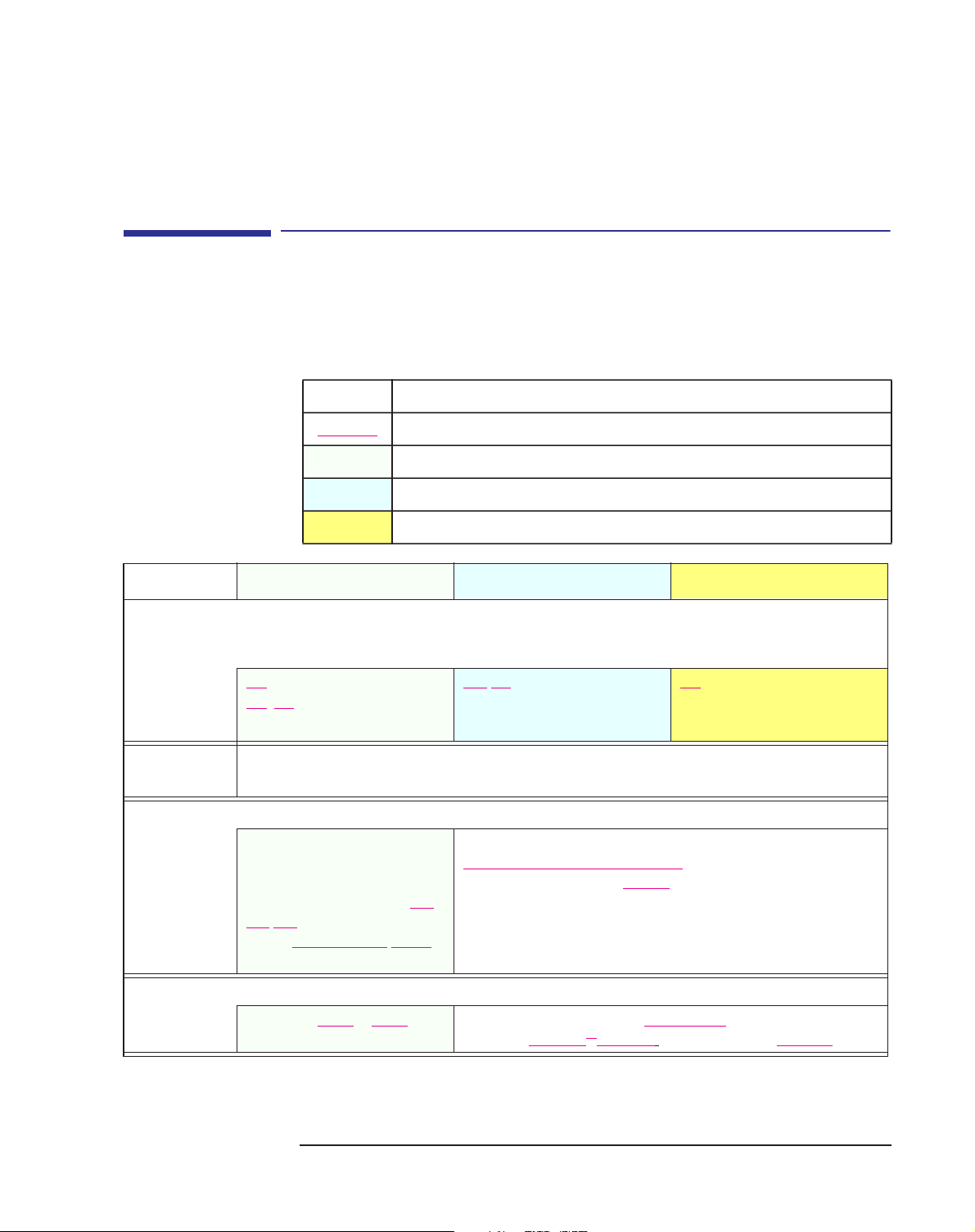
Front view
ear View
2 internal mass storage
shelves: 3.5-inch wide.
Upper shelf: 1-inch high
Lower shelf: 1.6-inch high
Power Supply
Up to six accessory boards
can be installed
Serial ports A and B
Mouse connector
HP MaxiLife LCD buttons
LCD Status panel
Two 3.5-inch wide shelf
(including the floppy disk drive)
Three 5.25-inch wide x
1.6-inch high front-access
shelves (including CD ROM
drive)
Audio Front Panel
Keyboard connector
Processor fan
Key lock
Parallel port
Line Out jack
MIDI/joystick connector
Line In jack
2 USB connectors
7
Power connector
MIC-in jack
Power supply fan
Display connector
Page 8
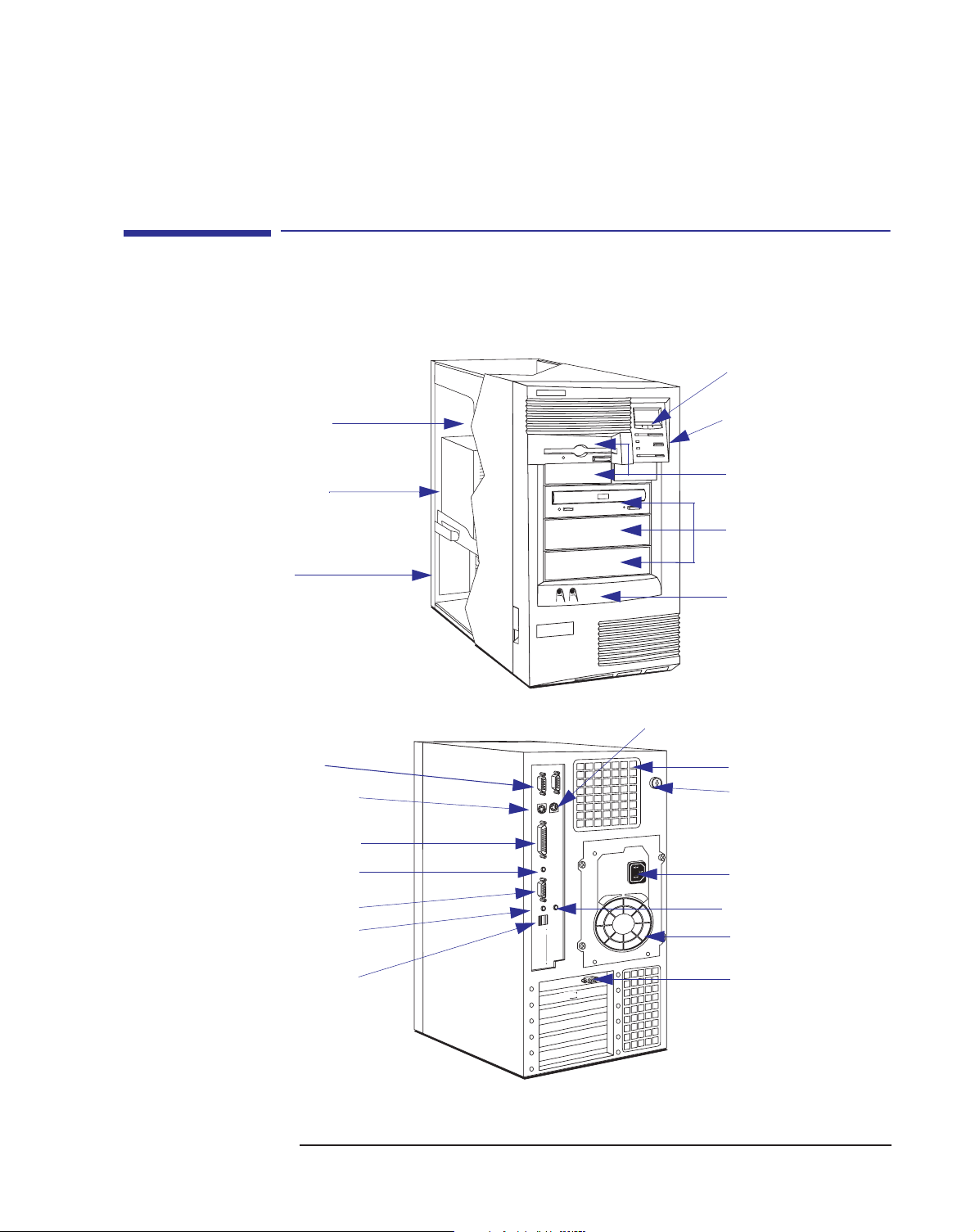
Removing the
Cover
Removing and Replacing the Cover
Removing and Replacing the Cover
The following procedures are valid for HP Kayak XA-s, XU Series 0301 and
0303, and XW Series U3 and W3 PC Workstations.
If necessary, unlock the cover. The lock and key for
the cover are at the back of the PC Workstation, just below
the rear panel connectors.
Lift the two latches
on the front sides of the
computer upwards.
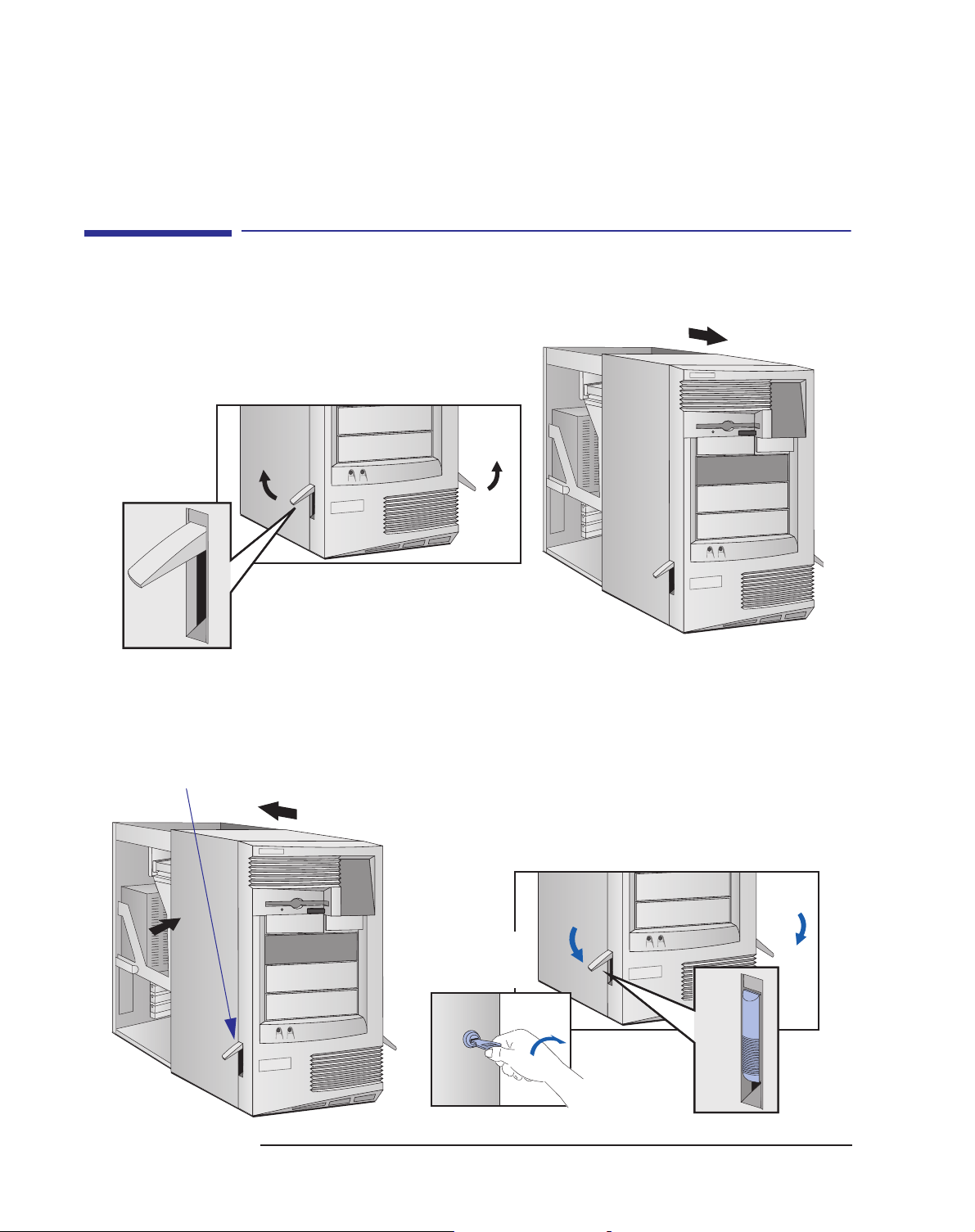
Replacing the
Cover
Ensure that the two latches on the front
sides of the cover are lifted up, and that the
lock is unlocked.
Grasp the cover on the sides at the back of the
computer and slide it forwards and off the computer.
Slide the cover onto the computer, making sure
that the two guides at the bottom of the case slide
into the two rails at the base of the computer.
Firmly slide the cover backwards into position.
If required,
lock the cover
using the key.
Lower the two latches on the front
sides of the cover.
8
Page 9
System Board Layouts
System Board Layouts
The connector layout on the system board is the same for HP Kayak XA-s,
XU Series 0301 and 0303, and XW Series U3 and W3 PC Workstations.
However, depending on the system specifications, the loading of certain
options can be different. The HP Kayak XU Series 0301 and 0303, and
XW Series U3 and W3 PC Workstations have one loading scheme and part
number. The HP Kayak XA-s PC Workstations use a different loading
scheme and part number.
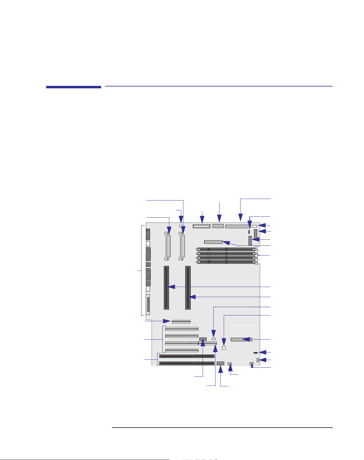
The different system board layouts are shown below:
HP Kayak XU and XW System Board Layout
Rear Panel
Connectors
VRM 2
VRM 1
Processor Fan
System Board Switches
Power Supply
a
Wide SCSI (16-bits)
External Battery
Disk Drive Fans
On/Off Status Panel
LCD Panel
FDD
4
3
Memory Modules
2
1
AGP Slot
PCI Slots
ISA Slots
9
Processor 1
Processor 2
Wake On Lan
I/O Cards Fan
IDE 1 Connector
Loudspeaker
Aux In Audio
CD In Audio
External Start
RAIDport Multimedia Panel
Options that are only available on HP XU and XW PC Workstations.
a. Refer to the Switch Block Label located on the chassis of the system box for the different
system board switch settings.
Mic In
Page 10
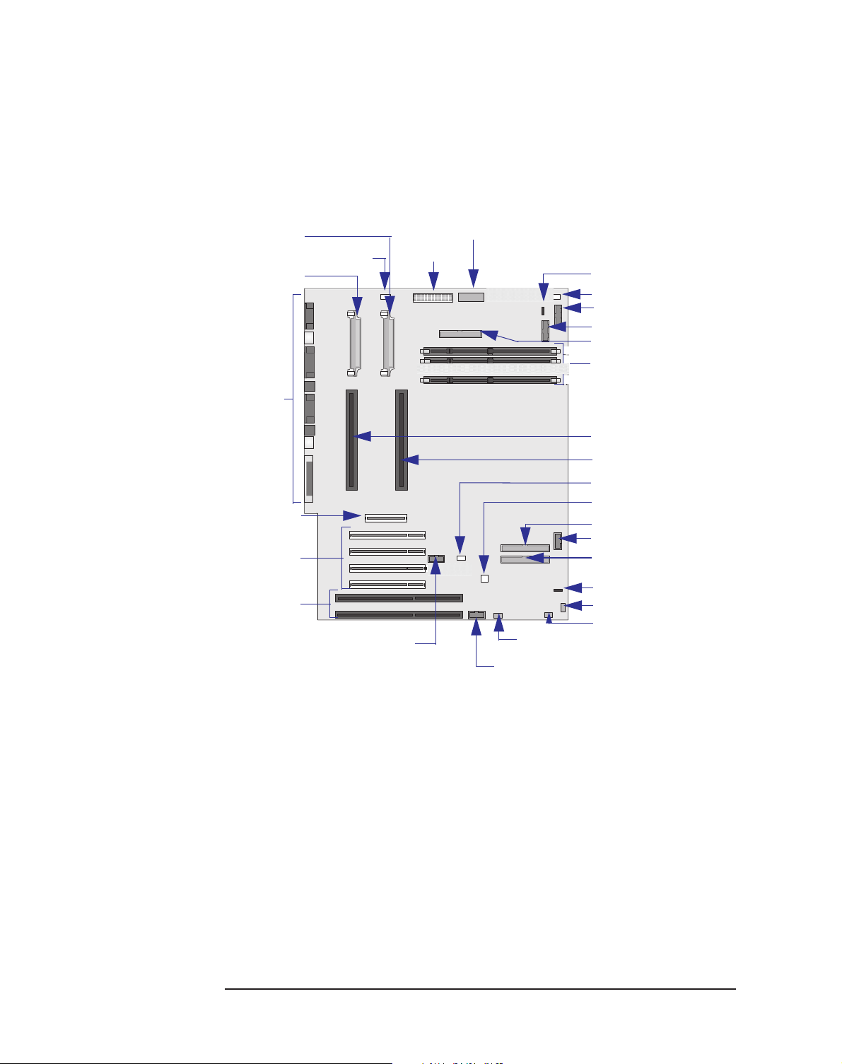
System Board Layouts
HP Kayak XA-s Minitower System Board Layout
Rear Panel
Connectors
AGP Slot
PCI Slots
ISA Slots
VRM 2
VRM 1
Processor Fan
System Board Switches
Power Supply
External Start
a
Mic In
Multimedia Panel
External Battery
Disk Drive Fans
On/Off Status Panel
LCD Panel
FDD
4
3
Memory Modules
1
Processor 1
Processor 2
Wake On Lan
I/O Cards Fan
IDE 2 Connector
LCD Status Panel
IDE 1 Connector
Loudspeaker
Aux In Audio
CD In Audio
b
b
b
c
10
a. Refer to the Switch Block Label located on the chassis of the system box for the different
system board switch settings.
b. Used only on Kayak XA-s Minitower PC models.
c. Used only on Kayak XA-s Desktop models.
Page 11
HP MaxiLife Utility
HP MaxiLife Utility
HP MaxiLife is a hardware monitoring chip which is resident on the system
board. This chip receives data about the various system components via a
dedicated I
error state (for example, there is a CPU failure), it displays a warning with a
flashing LED and message on its LCD that specifies which component has
the problem.
Due to HP MaxiLife’s system independent design, even if there is a serious
component failure, it remains in operation and is able to indicate what the
problem is via the LCD.
For the HP MaxiLife to work correctly, the PC Workstation must always be
connected to a grounded outlet. This enables the PC Workstation’s
hardware monitoring chip to be active, even if the system has been powered
off.
2
C bus. If it detects a potential error or that a component is in an
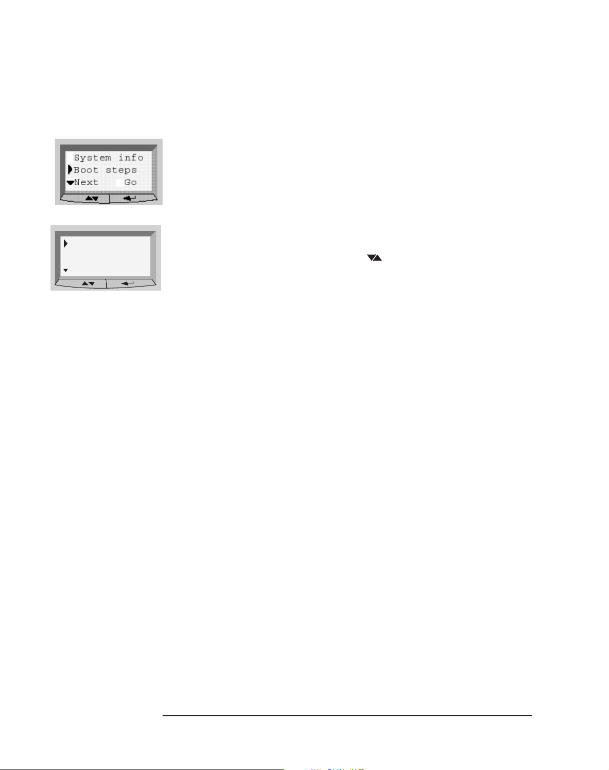
System info
Boot steps
Next Go
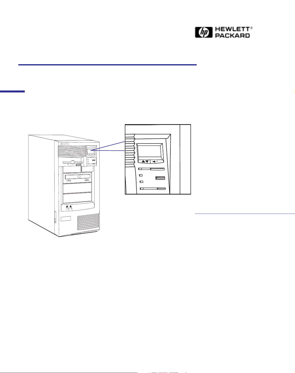
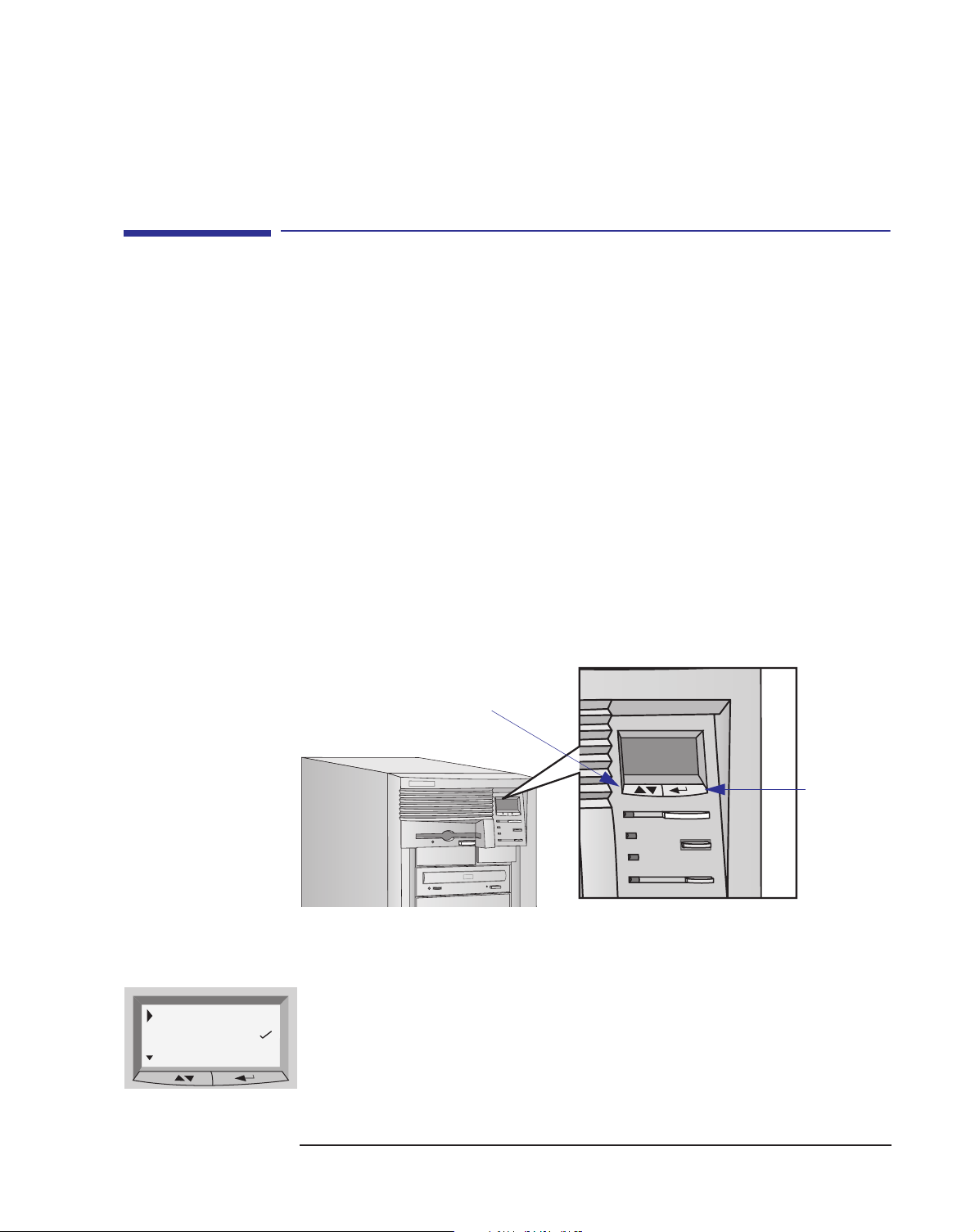
The following diagram shows where the LCD is located on the HP Kayak
XA-s, XU Series 0301 and 0303, and XW Series U3 and W3 PC Workstations.
Use this button to scroll
through the menu items
Use this button
to validate a
menu item
The following menus are available on the HP MaxiLife utility when pressing
the menu button:
• System Info. Obtains information from the BIOS and the system’s
Serial EEPROM from a previously successful boot. This information
includes: product name (HP Kayak XA-s, or XU, or XW) BIOS version,
serial number, the number of processors and speed, size of memory
for each DIMM socket.
11
Page 12
Diags
Exit
Next Go
HP MaxiLife Utility
• Boot Steps. Shows the Power-On Self Test (POST) codes during the
system startup. The POST code is provided by the BIOS and is
displayed on the LCD panel as soon as it is available. If the system
stops during the startup, the last successful boot step POST code is
displayed on the LCD.
Diagnostics. Runs a set of diagnostics assessing the system’s
components. Results of the tests are displayed on the LCD one after
another when the user presses the button.
Result of the diagnostics is: OK/FAIL.
Error Messages
When the PC is turned on (pressing the ON/OFF button), the system
initiates the normal startup sequence. A first diagnostic (called pre-boot
diagnostics) is run to check the presence of the processor, DIMM, VRM and
power supply.
MaxiLife does not purposely ‘freeze’ the system if an error is detected.
However, some critical hardware errors are fatal to the system and will
prevent the system from starting (for example, ‘Power’, ‘Board PLL’ are
serious malfunctions that will prevent the CPU to work correctly).
Errors that are not so critical (for example, ‘CPU Socket’ for missing
terminator, or ‘NO RAM’) are also detected by the POST and will abort its
own boot process after beeping. The ‘RAM type’ error is only detected by
POST with the same abort process.
Finally, while the PC is working, fan and temperature controls can be
reported (for example, a fan error when a cable is not connected). This type
of error disappears dynamically when the problem has been fixed (for
example, the fan cable has been reconnected).
If an error is detected, a screen appears on the LCD panel. The following
table shows the test sequence carried out, the type of error message, and
the action to take.The errors mentioned are standard error codes (they are
displayed without the need of pressing any key on the LCD status panel).
12
Page 13

Test Error Code Action to Take
HP MaxiLife Utility
1 When pressing one of the LCD status
panel buttons, nothing is displayed.
2 When the system is powered on, nothing is
LCD status panel is
blank
• Check that the two cables to the LCD status panel are properly
connected (refer to the system board layout for position).
• Check that the PC’s power cable is plugged in.
displayed.
Presence of either CPU or Terminator in the
CPU SOCKET • Check CPUs and Terminator and VRM of installed processor.
processor slot.
Control of some voltages: VRMs, 12V POWER SUPPLY • Check the power supply connectors, VRM, CPU. In a single
processor system, check that the VRM is not plugged into the
terminator socket.
The error message could also show: Power CPU1 and Power
CPU2.
Number of installed DIMMs NO RAM • Check that the memory module is correctly installed in the
memory socket.
Compatibility of DIMMs. The BIOS checks that
the inserted DIMMs are both compatible with
one another, and compatible with the Front Side
Bus frequency.
RAM TYPE • Check the installed memory modules. This error occurs when
mixing incompatible memory modules, for example, when
installing a 66 MHz DIMM on a 350 MHz or higher system, or
when mixing Unbuffered and Registered memory modules.
Check the system board clock generators (PLL). BOARD PLL • Check the power supply connector.
• Replace the system board (PLL clock generator).
Test of the correct power signals to the CPU.
The power supply may be OK, whereas the VRM
is not.
POWER • Check that the VRM, processor and terminator are correctly
installed.
• Check that the VRM is not plugged on a socket with a
terminator (this could be the likely cause).
• Check or replace the VRM.
• Check the power supply unit connectors.
Availability of video controller. It is also checked
by the BIOS. If an error is detected, it is not a
fatal one and the BIOS will continue its
execution normally.
In order to detect whether the CPU is able to run
a given code, HP MaxiLife waits for a
synchronization event from the BIOS. Any failure
that prevents the execution of the firmware will
trigger an error.
13
NO VIDEO • Check that the video controller is correctly installed.
Note: No error is detected if a monitor is not connected to an
installed video controller.
BIOS • Flash the latest version of the system BIOS by using the system
recovery procedure. Set switch 10 to the down position.
• Check that the RAM is correctly installed.
• Check that the CPU is firmly inserted.
Page 14
HP MaxiLife Utility
Test Error Code Action to Take
The BIOS then executes the Power On Self Test
(POST) sequence. In this phase, HP MaxiLife
waits for any error messages that the BIOS may
issue.
During normal usage of the PC, HP MaxiLife is
always checking vital parameters of the system.
If an error should occur, a message would be
automatically displayed on the LCD panel.
1.
Special cases: Board PLL = System board needs replacing. CPU error = Reset or power off the system to recover.
POST XXXX • If the screen is working, you can obtain the signification of the
error by typing “Enter” at the end of the POST. Or, you can
check the list of errors that are available on the HP World-Wide
Web support page.
TEMP IO SLOT • Check the connection of the corresponding component, which
could be: “Temp IO slot”, “Power errors, “Fan CPU”, “Board
PLL”, “Temp disk”, “Temp CPU”, “Fan disk”, “Fan IO slot”, “CPU
1
error”.
Special Cases 1 If a CPU is not installed correctly.
Either the “Power CPUx” or “CPU socket” or “BIOS” message may
appear. This will depend on which end of the CPU connector is not
correctly inserted.
2 If a VRM is installed and there is a terminator in the associated
CPU socket.
MaxiLife displays “Power” error message and the system does not
start
3 Only one pre-boot error reported on the system.
Hidden errors will be revealed when the current error has been
fixed.
4 If a “No Video Error” message is displayed, even though the video
is working correctly.
With some specific add-on boards (for example, 1540 from
Adaptec with SCSI BIOS), this error may appear while the system
is fully working. To check if this is the case, remove all add-on
boards from the basic system configuration.
14
Page 15

Running the MaxiLife Diagnostics Program
Running the MaxiLife Diagnostics Program
Can I run the HP MaxiLife Utility Diagnostics program when the
computer is powered off?
Yes, you can. However, the power cable must be connected to a
wall socket. The Diagnostics program will run low-level tests
on the memory, processor(s), VRM, power supply, video controller and the main clock generator on the system board
(Board PLL).
Even with the computer powered off (the LCD status panel will be blank),
HP MaxiLife is still running and monitoring the state of the LCD buttons. If,
one of the two buttons is pressed, the LCD status panel will display a second
menu. To run the diagnostics option, proceed as follows:
Press one of the LCD buttons, or to display the main screen.
5 Use the button to scroll through the menus until you reach the Di-
option. Then press the button.
ags
6 Use the button to select Power on. The main power supply is
started, enabling the hardware monitoring chip to assess the status of
the computer’s components.
NOTE Although the main power supply has been started, the computer does not
continue to complete a normal boot.
7 Use the button to scroll through the Diags option. The system
components are tested in sequence with the results being displayed
on the status panel. Press the Next button to move on to the following
test.
If no errors are detected, you can exit the test session by pressing
the button. The main power supply will be turned off and the
LCD status screen will become blank.
If an error is detected, a short message will be displayed indicating
which component has a problem.
For example: DIMM found:0
This indicates that there are no memory modules detected.
NOTE The display of a warning with a flashing LED and message on the LCD status
panel are not available when the computer has been powered off.
15
Page 16

Checking the System Configuration
Checking the System Configuration
I need to check the system configuration, and in particular the
BIOS version. Can this be checked from the LCD status panel?
Yes, it can. System configuration (including BIOS version)
can be checked through the System Info menu.
The System Info menu also provides information about the following
components:
• Product name (HP Kayak XA-s, or XU, or XW).
• Processors (number and speed).
• DIMMs (number and size of memory).
• Serial Number.
All information provided by the BIOS has been stored (during a normal
boot) into the serial EEPROM. This information is updated every time the
system is successfully rebooted.
To check the system configuration, proceed as follows:
1 Press one of the LCD buttons, or , to display the main screen.
The following menu is displayed.
2 To view the components in the System Info menu, use the button
to scroll through the information screens.
3 After the last item has been displayed, the LCD returns to the Main
screen.
16
Page 17

Checking the Display Screen
Checking the Display Screen
I have turned on the PC Workstation, but nothing appears on the
screen. How can I find out what the problem is?
Check the LCD status panel screen for an error message (a
table on page 13 lists all the different types error messages
and action to take to solve them).
When the PC is turned on, the HP MaxiLife diagnostics utility will first check
the system components before it initiates the system startup sequence. If it
detects an error at this stage of the pre-boot checks, an error screen will be
displayed on the LCD status panel. If no errors are found, another screen
with a “smiling icon” will be displayed.
Error!
Board PLL
An example of an error screen that could appear on
the LCD status panel.
Following the pre-boot checks, the POST sequence is then initiated. If an
error is detected, a POST Error code is displayed. Refer to the POST error
codes table contained in the Service Handbook for further explanation.
Error!
POST XXXX
An example of a POST error code screen that could
appear on the LCD status panel.
HP KAYAK XU
This screen indicates that the pre-boot checks have
not found any errors.
HP KAYAK XU
This screen indicates that no errors have been
found.
17
Page 18

Checking the Display Screen
You can also use the Boot Steps option from the LCD status panel. It shows
the POST steps during the system startup. If the system stops during the
startup, the last successful boot step POST code is displayed on the LCD
status panel. For support purposes, POST steps are only shown as POST
codes. To access
1 Press one of the LCD buttons, or , to display the main screen.
2 Use the button to scroll through the menus until you reach the
Boot steps option. Then press the button.
Boot Steps, proceed as follows:
For further details on the HP MaxiLife diagnostics utility, refer to the User’s
Guide. This provides examples of error screens arising from pre-boot checks
and explains how to configure the HP LCD control buttons.
You can also obtain details of POST codes and POST error codes from the
HP World Wide Web site: http//www.hp.com/go/kayaksupport,
select the required platform, documentations, then choose the document
dealing with MaxiLife or LCD errors.
18
Page 19

Upgrading Main Memory Modules
Upgrading Main Memory Modules
The PC Workstation has 64 MB of Non-ECC SDRAM main memory
installed in one DIMM slot. Can a 256 MB ECC SDRAM memory
module be added to a second DIMM slot to upgrade the memory?
No. To upgrade the memory, you can use 64 MB or 128 MB
memory modules (either ECC or Non-ECC). Or, alternatively,
replace the existing 64 MB memory module and install a 256
MB ECC SDRAM memory module.
Main memory modules are available in 64 MB, 128 MB and 256 MB ECC
SDRAM modules. However, it is important
MB modules are non-buffered ECC SDRAM modules, while the 256 MB
modules are registered ECC SDRAM modules. Refer to the table on page 5
for details on how much main memory can be installed on each PC
Workstation.
to note that the 64MB and 128
Error!
RAM type
Mixing Memory Modules
Unbuffered and Registered ECC modules are not compatible with each
other, and cannot be mixed. If these have been mixed, this will be
detected in the basic pre-boot tests when you boot the system for the
first time. The BIOS checks that the inserted DIMMs are compatible with
one another, and if it detects an error, it is reported to the HP MaxiLife.
The error message (shown on the left) will then be displayed on the LCD
status panel. Refer to the following table for DIMM compatibility rules.
Original DIMM Type Adding Non-ECC
Non-ECC
Unbuffered ECC
Registered ECC
(256 MB)
1.
All DIMMs will function as Non-ECC.
HP XU and XW PC Workstations support only ECC DIMMs.
Yes Yes
1
Yes
No No Yes
Adding
Unbuffered ECC
1
1
Yes
Adding Registered
ECC (256 MB)
No
No
19
Page 20

Installing the OpenGL Graphics Drivers
Installing the OpenGL Graphics Drivers
On the HP Kayak XW Series U3 and W3 PC Workstation
OpenGL graphics drivers are available for both the AccelEclipse and
Visualize FX4 video controllers for use under Windows NT4.0 only. Without
the appropriate drivers, the PC Workstation will only operate in VGA mode,
meaning that the 3D hardware accessory will not be available.
NOTE Graphics drivers are regularly updated by Hewlett-Packard for feature and
performance improvements. When installing a driver, or diagnosing an error,
you are strongly recommended to check that you have the latest driver
version. These can be found on the HP World Wide Web site:
http//www.hp.com/go/kayaksupport
Installing the OpenGL Graphics Drivers
Installation of the drivers is done through the standard process:
Display Properties / Settings / Display Type
Configuring the AccelEclipse OpenGL Driver
Once the driver is installed, an ‘AccelEclipse’ tab is added to the Display
Properties dialog box.
Advanced users:
further options
are available on
the System
Driver
version
Settings tab
Select the
application to be
used
Select Factory
Settings to reset
all driver options
to the default
settings
Click the
Configure button
to modify driver
options
20
Page 21

Installing the OpenGL Graphics Drivers
Configuring the Visualize FX4 OpenGL Driver
Once the driver is installed, three new tabs are added to the Display
Properties dialog box: Options, Gamma Correction, and About.
Check for driver version
in the About tab
Check for texture module
(optional upgrade, part
number D5511A)
Contextual help
available for
each of the
advanced
options
Select the application
to be used in the
Options tab
Advanced users:
select Advanced to
reveal further options
NOTE The ‘Conservative Hardware Access’ option in the Advanced option list
provides increased graphics stability by restricting access to the AGP bus.
Use this option if the system appears unstable when combining intensive
graphics and extensive hard disk accesses.
21
Page 22

Using Video Diagnostics Utilities
Using Video Diagnostics Utilities
On the HP Kayak XW Series W3 PC Workstation
Visualize FX4 Diagnostic Utility
A diagnostics utility for the Visualize FX4 video controller is preinstalled on
the hard disk. To run this utility,
Start/Programs/HP Diagnostics/HP Visualize FX4 Diagnostic
The diagnostic utility can also be found on the Drivers CD-ROM (delivered
with the PC Workstation) or on the HP World Wide Web site (refer to page
33 for the WWW address).
This utility can be used only when Windows NT is running and the Visualize
FX4 OpenGL driver is installed. It provides a good level of confidence in the
graphics hardware in situations such as intermittent system hangs or
unusual graphic behavior on the screen.
22
Test results Pass or Fail
Page 23

Changing a Switch Setting on the System Board
Changing a Switch Setting on the
System Board
I have enabled switch 10 to activate the BootBlock recovery
process, but it doesn’t work. Is this the correct switch to change?
Yes, it is the correct switch. Check that the switch has been
correctly set, and that your boot diskette is correctly configured. Refer to the Kayak service handbook for details.
When changing a switch setting to the “down” position on the system board
switch bank, you must push the slide switch completely across. If the switch
stops in the middle, there is no change to the configuration.
NOTE Switch 10 also enables the HP MaxiLife firmware ‘crisis’ block if the power
cord is unplugged. In this case, the LCD status panel is not available and the
screen stays blank.
Solving Audio Problems
What do I do if I encounter any audio problems.
The volume level on the HP Kayak Workstation PCs is controlled by the Mute and Volume keys through the HP
Enhanced Keyboard. First, check if the Mute key has not been
muted by mistake, If it has, press it to restore the audio
functions.
If this does not solve the problem, refer to the guide Using Sound,
preloaded on the PC Workstation for details on how to test and solve any
problems with audio features.
23
Page 24

Configuring SCSI Channels on HP Kayak XA-s
Configuring SCSI Channels on HP Kayak XA-s
Even after validating the SCSI channel in the BIOS setup
(through the Advanced Menu), UltraWide SCSI (Symbios), there
is still no SCSI HDD selected in the boot menu. Why is this?
The HP Kayak XA-s PC Workstations (minitower models), do
not have a SCSI controller. Only the IDE hard disk drives
should be in the boot menu.
In the BIOS, even though the SCSI controllers are displayed and can be
configured, the settings will not be used.
The SCSI on-board controller (not integrated on the system board) is not
preloaded on the HP Kayak XA-s. The UltraWide SCSI controller (Symbios)
is an add-on board that is provided on selected HP Kayak XA-s desktop
models only.
24
Page 25

Identifying Video Cards on HP Kayak XA-s
Identifying Video Cards on HP Kayak XA-s
When booting a Windows NT 4.0 system on an HP Kayak XA-s PC
Workstation, the logon screen is corrupted by a grid pattern. What
is causing this problem?
A Matrox Millennium II AGP driver for HP Kayak XU PC
Workstations has been installed instead of a Matrox
Productiva G100 driver for HP Kayak XA-s.
The Matrox Productiva G100 AGP has 100 MHz of SDRAM video, while the
Millennium II AGP has 250 MHz of WRAM video. Video drivers have to
accommodate this frequency difference. To overcome this problem, Matrox
may eventually deliver a driver roll unifying both sets of frequencies in one
package.
The following diagram is an example of a logon screen that has been
corrupted due to an installed video driver which is not compatible with the
video adapter.
Logon screen
corrupted by a
grid pattern
25
Page 26

Identifying Video Cards on HP Kayak XA-s
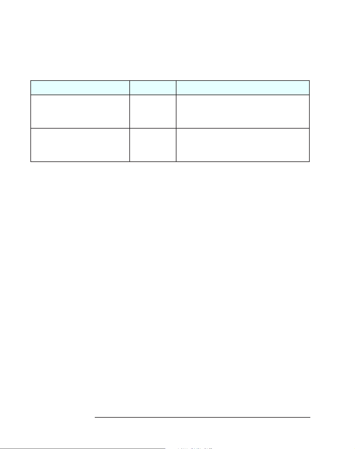
The following table shows the correct video driver versions to be used with
the different video adapters installed on a Windows 95 operating system.
The HP Kayak XU
1
has a preloaded video driver that isn’t compatible with
the more recent Matrox Productiva G100 video adapter. This means that the
Matrox Millennium video driver cannot be used with the Matrox Productiva
G100 video adapter.
WINDOWS 95
Video Adapter
XA-s Matrox Productiva G100 YES NO
XU Matrox Millennium II AGP NO YES
Video Driver Version
3.82b16
Video Driver Version
3.70b07
The following table shows the correct video driver versions to be used with
the different video adapters installed on a Windows NT 4.0 operating
system. The Matrox Productiva G100 video adapter is backward compatible
enabling it to be used with the Matrox Millennium II AGP video driver on the
HP Kayak XU PC.
WINDOWS NT 4.0
Video Adapter
XA-s Matrox Productiva G100 YES NO
XU Matrox Millennium II AGP OK YES
Video Driver Version
3.32b85a
Video Driver Version
3.20b65
1. For the Matrox Millennium G200, new video drivers are required.
26
Page 27

Identifying a Video Board On An HP Kayak XU
Identifying a Video Board On An HP Kayak XU
How do I identify whether an HP Kayak XU has a Matrox
Millennium II video board or a Matrox Millennium G200?
Check the Support label on the back of the PC (this could be
either on the right or left-hand side of the box).
The Matrox Millennium II Kayak XU model is labeled:
XU6/XXXserie0301.
The Matrox Millennium G200 Kayak XU model is labeled:
XU6/XXXserie0303.
XXX = processor speed.
Why You Need to Differentiate Between These Two Models
When downloading the video drivers from the HP World-Wide Web site, it is
very important that you know which HP Kayak XU model you are upgrading.
This is because the video drivers may not be compatible between the
different video controllers.
Also, when upgrading the video memory on the Matrox Millennium II, the
WRAM memory modules are not compatible with the Matrox Millennium
G200, which uses SGRAM modules.
When you add other PCI video adapters for multi-screen environments, you
also need to know the difference between the HP Kayak XU Series 0301 and
0303 models. Multi-screen is only fully supported when installing two
Millennium II (AGP + PCI) or two Millennium G200 (AGP + PCI) video
boards. Mixing Millennium II and the Millennium G200 video boards is not
currently supported by Hewlett-Packard.
Check the HP World-Wide support page for up-to-date information, at
http//www.hp.com/go/kayaksupport.
You may also need to know which HP Kayak XU model you are using when
downloading specific accessories from Matrox.
27
Page 28
Replacing a Failed Hard Disk on a FastRAID System
Replacing a Failed Hard Disk on a FastRAID System
On HP Kayak XU Series 0301 and 0303,
and XW Series U3 and W3 PC Workstations
I have a FastRAID system that includes two hard disk drives.
However, one of the hard disk drives needs to be replaced. How
do I reconfigure the FastRAID I/O subsystem?
You will have to rebuild the Array and reinstall the FastRAID
drivers. To do this, however, the ArrayConfig program and HP
FastRAID drivers must be copied onto floppy disks.
Revisions of software between first generation of the FastRAID
board and the new generation (FastRAID2) are not compatible.
Refer to page 6
and page 31.
With the second generation of the FastRAID board (FastRAID2), new
software is available and can only be used. This software is not compatible
with any previous versions of the FastRAID board.
To reconfigure the new hard disk drive, proceed as follows:
1 From another PC, you have to create two bootable floppy disks. To do
this, copy the following directories from the Kayak Drivers and Documentation CD-ROM to the floppy disks:
a ArrayConfig. You need this to rebuild the arrays.
b FastRAID driver. You need this to install the Adaptec Array1000™
drivers.
More information concerning configuring or obtaining drivers can
be obtained from the HP World Wide Web site:
http//www/hp.com/go/kayaksupport
Insert the ArrayConfig floppy disk in the PC that has the new hard
2
disk drive and boot the computer. Follow the instructions that appear
on the screen. If you need any assistance on creating an Array, refer
to the User’s Guide.
3 When the disk array has been rebuilt, boot from the Windows NT 4.0
floppy disks. When requested, specify additional devices, insert the
floppy disk containing the Array1000 drivers, and follow the
instructions on the screen.
NOTE Do not boot from the Windows NT CD-ROM as the hard disk drive will not be
found.
28
Page 29

Enabling a SCSI Controller
Enabling a SCSI Controller
On HP Kayak XU Series 0301 and 0303,
and XW Series U3 and W3 PC Workstations
I have an HP Kayak PC Workstation and I would like to change the
Boot device from the BIOS between two SCSI controllers, one of
which is connected to the UltraWide (Adaptec) SCSI controller
and the add-on SCSI controller (Symbios).
You cannot load the two SCSI BIOS systems at the same time.
However, it should be noted that if you decide to boot from an
external SCSI device, you will not be able to access the UltraWide SCSI hard disk drive from DOS. Loading the correct
SCSI drivers enables access of the Ultra-Wide SCSI hard disk
drive from Windows NT.
The integrated UltraWide SCSI controller is configured using the SCSISelect
utility. This utility must be used if the HP FastRAID option is installed. With
the add-on SCSI controller, it is configured using the Symbios Logic SCSI
Configuration Utility. These two utilities cannot be loaded at the same time.
Depending on the required SCSI option, only one of them can be enabled.
Use the HP Setup program to enable and disable the required SCSI
controllers. To do this, proceed as follows:
1 Press during the Power-On Self Test (POST), while the initial
“Kayak” logo is displayed, immediately after restarting the PC.
2 Select the Advanced menu. From this sub-menu, you can then either
enable or disable the following options:
a Internal SCSI 16 Bits (Adaptec)
b External/Internal 16/8 Bits (Symbios)
For example, if you wish to use the Symbios BIOS:
From the External/Internal 16/8 Bits (Symbios) sub-menu, set
Option ROM Scan (Enabled)
From the Internal SCSI 16 Bits (Adaptec) sub-menu, set
Option ROM Scan (Disabled)
If you wish to change the setting, repeat the above steps, and reverse
the enabled and disabled options.
3 Save your changes and exit the Setup program.
29
Page 30

Identifying the Kayak XW Series U3 and W3 PC Workstation
Identifying the Kayak XW Series U3 and W3
PC Workstation
How can I distinguish an HP Kayak XW PC Workstation Series
U3 or W3 from any previous XW platforms?
There are two simple and quick ways to identify the model.
First, check the Support label on the back or side of the PC.
Secondly, check the front panel. The XW Series U3 and W3
front panel includes the HP LCD status panel.
The following is an example of a support label showing exact locations of the
Series identifier.
Series is indicated on
Support label
It should be noted that identifying a video controller is not sufficient to
identify the HP Kayak XW model. The following table shows the differences
between the various platforms and the associated video controller.
Model Video Controllers
HP Kayak XW Series W3 HP Visualize FX4
HP Kayak XW Series W2 HP Visualize FX4
HP Kayak XW Series U3 AccelEclipse II AGP
HP Kayak XW Series U2 AccelEclipse II
HP Kayak XW Series A2 Elsa Gloria Synergy
30
Page 31

Identifying the Latest Kayak XU PC Workstation
Identifying the Latest Kayak XU PC Workstation
How can I distinguish the difference between the latest HP Kayak
XU Series 0301 or 0303 models (introduced after June/July 1998),
and the previous HP Kayak XU model (introduced in Fall 1997)?
There are four simple and quick ways to identify the latest HP
Kayak XU model. First, there is the new HP MaxiLife LCD status
panel. Secondly, the processor frequency is 350 MHz or higher.
Thirdly, the model numbers are different, and finally the label
on the side of the newer Kayak XU indicating “Series 0301” or
“Series 0303”.
As well as the above-mentioned differences between the two HP Kayak XU
models, there is also a higher level of system performance due to the 100
MHz system bus (Front Side Bus) with the Intel 440BX AGP chipset
(compared to 66 MHz on the earlier models). The following table shows
some of the new features on the latest HP Kayak XU models.
Component HP Kayak XU Series 0301 and 0303 (Introduced June/July ‘98)
Processor Frequency Speeds and Model
List
HP MaxiLife For maximized reliability and up-time. A dedicated chip and bus, that surveys the PC and
Memory Support Up to 1 GB of SDRAM memory (using 4 x 256 MB of registered memory modules).
Processor Fan connector rotated at 90°
SCSI holder protection on the side The transparent plastic protection holder protects the narrow SCSI cable and also the power
Front panel sound volume control Has been removed.
Fan wires Two (2) wires instead of three (3).
External SCSI channel Is now 16 bits (wide) instead of 8 bits (narrow).
Internal SCSI connectors More space between 2 narrow SCSI connectors, and 2
FastRAID sub-system New generation FastRAID 2 board (reported RAIDport II when FastRAID BIOS is loaded during
6/350: D5680N
6/400: D5682N, D5683N, D5684N
informs you in detail on an LCD display on the front panel.
The fan cable no longer touches the cover when the cover is removed and replaced.
cables when the cover is removed and replaced.
nd
and 3rd wide SCSI connectors.
POST).
31
Page 32

Installing 10krpm Hard Disk Drives on a Kayak XU
Installing 10krpm Hard Disk Drives on a Kayak XU
How many 10 krpm hard disk drives can be installed in the
internal shelves on the HP Kayak XU Series 0301 and 0303
PC Workstation?
You can install up to two (2) 9.1 GB Low Profile (LP) SCSI
hard disk drives in the internal shelves.
The HP Kayak XU Series 0301 and 0303 PC Workstation contains seven
mass storage shelves:
• Two internal mass storage shelves (3.5-inch wide):
Top internal shelf. A 1-inch high hard disk drive can only be
installed in this shelf. This could be either a 4.5 GB or 9.1 GB low
profile hard disk drive.
Lower internal shelf. A 1.6-inch high hard disk drive can be
installed this shelf. It can also shelve the low profile (1-inch in
height).
• Five front-access shelves:
To ensure that hard disk drives are properly installed and cooled,
you should only install hard disk drives up to 1-inch in height and
of a speed equal to or less than 7.2 krpm in these shelves. Because
there is not enough air flow in the front-access shelves, 10 krpm
hard disk drives cannot be installed.
Two internal mass storage
shelves (3.5-inch wide).
Upper shelf: 1-inch high
Lower shelf: 1.6-inch high
Two 3.5-inch wide
low-profile shelves
Three 5.25-inch
wide 1.6-inch frontaccess shelves, but
only support 1-inch
high hard disk drives
32
Page 33

Flashing the Latest Version of the System BIOS
Flashing the Latest Version of the System BIOS
BIOS upgrades can be downloaded from the HP World Wide Web site (see
below for the World-Wide Web URL). To download a BIOS upgrade, connect
to the HP Web site and follow the on-screen instructions to download the
flash utility programs (
BIOS file (
HK1xxxyy.FUL), and a file called platform.bin, onto a bootable
diskette.
When you’ve downloaded the files, insert the diskette in drive A and re-boot
the computer. Enter the command in the following format
PHLASH /c HK1xxxyy.FUL
to update the firmware of the LCD for a clean configuration
/c
(except the date and time).
FLASH.BAT, AUTOEXEC.BAT and PHLASH.EXE), the
Access HP World Wide
Web Site
xxx replaced by the version that you have downloaded.
yy language that you have downloaded.
World-Wide Web URL http://www.hp.com/go/kayaksupport
33
Page 34

Complete the Questionnaire to Check Your Understanding
Complete the Questionnaire
to Check Your Understanding
Circle each letter that corresponds to a correct answer. (There may be more
than one correct answer to each question).
1 Can a 256 MB registered ECC memory module be mixed with a
non-buffered ECC SDRAM memory?
a Yes, it can. However, the 256 MB module must be installed in
Slot 1.
b No, it cannot. Registered and non-buffered memory modules are
not compatible.
2 Can a maximum of 512 MB of non-buffered ECC SDRAM memory
modules be installed on HP Kayak XA-s, XU Series 0301 and 0303,
and XW Series U3 and W3 PC Workstations?
a Yes, by installing 4 x 128 MB memory modules.
b No. On the HP Kayak XA-s, there are only three DIMM sockets
available.
3 For models with the HP FastRAID2 I/O Subsystem, can you boot
from the Windows NT CD-ROM when replacing a disk drive?
a Yes, because Windows NT is capable of finding a new hard disk
drive.
b No, because the new hard drive will not be found.
4 Where can you find all of the HP FastRAID software (ArrayConfig,
drivers and CI/O Manager) and Operating System Installation
notes (such as Windows NT 4.0)?
a HP Kayak XU/XW PC Workstation Drivers CD-ROM.
b HP’s WWW site.
c Netscape Communicator CD-ROM.
5 To run the MaxiLife diagnostics program, does the computer
need to be powered on?
a No, it doesn’t. The HP MaxiLife is always running and continuously
monitors the state of the LCD buttons.
b Yes, it does. This can be easily checked, because the LCD status
panel will be blank.
34
Page 35

Complete the Questionnaire to Check Your Understanding
c No, it doesn’t. Even with the power cable disconnected, HP
MaxiLife is always running and continuously monitors the state of
the LCD buttons state.
6 Can the Internal SCSI 16 Bits (Adaptec) and External/Internal 16/
8 Bits (Symbios) utilities be set to enabled at the same time?
a Yes, they can. From the BIOS, select the Advanced menu. Then
you can enable the Option ROM Scan for both utilities.
b No, these two utilities cannot be loaded at the same time.
c This is not possible on HP Kayak XA-s PC Workstations.
7 A Matrox Productiva G100 video adapter has been installed in an
HP Kayak XU PC Workstation. How will it work?
a It will work well.
b It will work slowly.
c It will work faster.
d It will not work at all.
8 A Matrox Millennium II AGP video adapter has been installed in
an HP Kayak XA-s PC Workstation. How will it work?
a It will work well.
b It will work slowly.
c It will work faster.
d It will not work at all.
9 A client has an HP Kayak XW with an AccelEclipse video
controller. The video controller has failed and needs replacing.
Which of the following is (are) true?
a All HP Kayak XW systems use the same video controller, so the
replacement part number from any HP Kayak XW system will be
the correct one for this system as well.
b The only way to determine the correct replacement video control-
ler is to remove the failed controller from the system to identify the
part number.
c There are several versions of the AccelEclipse video controller
used on HP Kayak XW systems, so I need to be careful in identifying the correct one.
35
Page 36

Complete the Questionnaire to Check Your Understanding
d It must be an HP Kayak XW Series U3. This is the only HP Kayak
XW model that uses the AccelEclipse video controller.
10 Which of the following statements about drivers is (are) correct?
a The most recent drivers are available on the HP World Wide Web
site.
b The HP Kayak XW OpenGL video driver is compatible with both
the AccelEclipse and the Visualize FX4 video controllers.
c The OpenGL video driver will detect the applications being used
and configure itself automatically to give optimal performance.
d Online help is available for the options in the video driver applet.
11 A client using an HP Kayak XW Series W3 PC Workstation is
calling about unusual graphics behavior on the screen. Which of
the following suggestions could be helpful?
a Run the Visualize FX4 diagnostics utility that is preinstalled on the
hard disk.
b Ask the client to uninstall the driver, and then see if the problem
disappears.
c From the Visualize FX4 video driver applet, select the Advanced
option then Conservative Hardware Access.
d Download the latest OpenGL graphic driver from the HP World
Wide Web site.
12 How do I find out which version of the FastRAID board is being
used (FastRAID1 or FastRAID2)?
a Check the part number marked on the board.
b Check the BIOS Summary Screen.
c Check the FastRAID BIOS banner during Power-On Self-Test
(POST).
36
Page 37

Complete the Questionnaire to Check Your Understanding
13 Before installing or replacing a component, do I need to use a
wrist strap and ESD mat?
a Yes, you do. Electrostatic Discharge (ESD) can damage proces-
sors, memory, hard disk drives, accessory boards and other components.
b No, you do not have to. The ESD package is non-conductive and
are now manufactured with a special anti-static product.
14 How do I identify whether an HP Kayak XU has a Matrox
Millennium II video board or a Matrox Millennium G200?
a Check the Support label on the back of the box.
b Check the part number on the back of the box.
c Check the video connector.
15 Can I upgrade a Matrox Millennium II video board using SGRAM
memory modules?
a Yes, you can. SGRAM memory modules are compatible with both
the Millennium II and Millennium G200 video boards.
b No, you cannot. Millennium II uses WRAM memory modules, while
the Millennium G200 uses SGRAM modules.
c Yes, you can. SGRAM memory modules are only used in the
Millennium II video boards.
37
Page 38

Answers and Explanations
Answers and Explanations
1 Can a 256 MB registered ECC memory module be mixed with a
non-buffered ECC SDRAM memory module?
b No, it cannot. Registered and non-buffered memory modules are
not compatible.
2 Can a maximum of 512 MB of non-buffered ECC SDRAM memory
modules be installed on HP Kayak XA-s, XU, and XW Series U3
and W3 PC Workstations?
b No. On the HP Kayak XA-s, there are only three DIMM sockets
available.
3 For models with the HP FastRAID2 I/O Subsystem, can you boot
from the Windows NT CD-ROM when replacing a disk drive?
b No, because the new hard drive will not be found.
4 Where can you find all of the HP FastRAID software (ArrayConfig,
drivers and CI/O Manager) and Operating System Installation
notes (such as Windows NT 4.0)?
a & b The HP Kayak XU/XW PC Workstation Drivers CD-ROM
contains this software. The most recent updates may be obtained
from the HP WWW site.
5 To run the MaxiLife diagnostics program, does the computer
need to be powered on?
b No, it doesn’t. The HP MaxiLife is always running and
continuously monitors the state of the LCD buttons. (The power
cable must always be connected.)
6 Can the Internal SCSI 16 Bits (Adaptec) and External/Internal 16/
8 Bits (Symbios) options be set to enabled at the same time?
b No, these two utilities cannot be loaded at the same time.
c This is not possible on HP Kayak XA-s PC Workstations.
38
Page 39

Answers and Explanations
7 A Matrox Productiva G100 video adapter has been installed in an
HP Kayak XU PC Workstation. How will it work?
d It will not work at all.
The HP Kayak XU PC Workstation has a preloaded Matrox
Millennium II AGP video driver that does not work with the more
recent Matrox Productiva G100 video adapter.
8 A Matrox Millennium II AGP video adapter has been installed in
an HP Kayak XA-s PC Workstation. How will it work?
c It will work faster.
The Matrox Productiva G100 video driver is backward compatible
and is able to accommodate the Matrox Millennium II 250 MHz.
9 A client has an HP Kayak XW with an AccelEclipse video
controller. The video controller has failed and needs replacing.
Which of the following is (are) true?
c Both the Kayak XW Series U3 and the Kayak XW Series U2 use an
AccelEclipse video controller. The Series U2 uses a PCI board,
whereas the Series U3 uses an AGP. Make sure you check the
series number on the Support label.
Note: Answer “b” would work, but requires removing the video
controller from the PC.
10 Which of the following statements about OpenGL video drivers on
the HP Kayak XW is (are) correct?
a The most recent drivers are available on the HP World Wide Web
site:
http//www.hp.com/go/kayaksupport
d Online help is available for the options in the video driver applet.
Note: With regard to Answer “c”, for both the AccelEclipse and
Visualize drivers, optimal performance can be obtained by selecting
the appropriate application in the video driver applet.
39
Page 40

Answers and Explanations
11 A client using an HP Kayak XW Series W3 PC Workstation is
calling about unusual graphics behavior on the screen. Which of
the following suggestions could be helpful?
a Run the Visualize FX4 diagnostics utility that is preinstalled on
the hard disk.
c From the Visualize FX4 video driver applet, select the Advanced
option then Conservative Hardware Access.
d Download the latest OpenGL graphic driver from the HP WWW
site.
12 How do I find out which version of the FastRAID board is being
used (FastRAID1 or FastRAID2)?
a The part number is marked on the FastRAID board. The part
number is also available in the Service Handbook.
FastRAID1 = 5064-1874
FastRAID2 = 5064-3668
1
(ARO1130A)
1
(ARO1130B)
c The FastRAID BIOS banner is displayed during Power-On Self-
Test (POST). Depending on the FastRAID board, the Adaptec
banner is different.
FastRAID2 = “RAIDport II”. Otherwise, no RAIDport is displayed.
A FastRAID1 board can be used in HP Kayak XU and XW PC Workstations with a processor up to 333MHz. While, a FastRAID2 board can
only be used in HP Kayak XU and XW PC Workstations from 350 MHz.
The software used for FastRAID1 and FastRAID2 is only available in
English. However, it should be noted that the software between the
two generations of FastRAID are not compatible (ArrayConfig, Drivers and
CI/O manager).
1. Part number is from the Kayak Service Handbook.
40
Page 41

Answers and Explanations
13 Before installing or replacing a component, do I need to use a wrist
strap and ESD mat?
a Yes, you do. Electrostatic Discharge (ESD) can damage
processors, memory, hard disk drives, accessory boards and
other components.
The ESD package is conductive and is easy to recognize from its
label. Do not take the new component out of its ESD package before
connecting your wrist strap and ESD mat to a suitable earthed point.
Also, do not forget to use the ESD package provided with the new
part to return the old one.
14 How do I identify whether an HP Kayak XU has a Matrox
Millennium II video board or a Matrox Millennium G200?
a Check the Support label on the back of the box.
The Matrox Millennium II Kayak XU model is labeled:
XU6/XXXserie0301.
The Matrox Millennium G200 Kayak XU model is labeled:
XU6/XXXserie0303.
15 Can I upgrade a Matrox Millennium II video board using SGRAM
memory modules?
b No, you cannot. Millennium II uses WRAM memory modules,
while the Millennium G200 uses SGRAM modules.
41
Page 42

Answers and Explanations
42
Page 43

Electrostatic Discharge Warning
Electrostatic Discharge (ESD) can damage processors, memory,
hard disk drives, accessory boards and other components.
The ESD package is conductive and is easy to recognize from its
label.
Before installing or replacing a component:
1 Do not take the new component out of its ESD package before
connecting your wrist strap and ESD mat to a suitable earthed
point.
2 Do not forget to use the ESD package
provided with the new part to return
the old one.
The ESD package is conductive and
is easy to recognize from its label.
Page 44

Manual Part Number:
D5699-90901 — Revision B
 Loading...