

Page 1
HP Kayak
PC Workstation
Service Handbook
PC Workstations and
Accessories
4th Edition
June 2000
Page 2
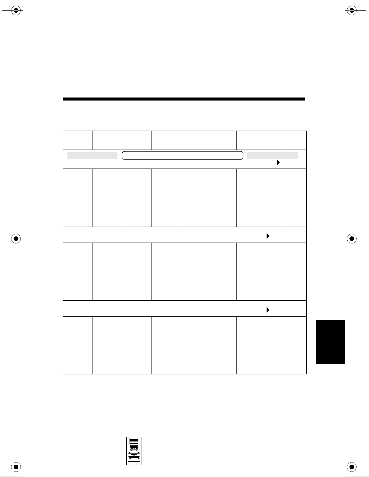
HP Kayak XA-s MT Series 02xx
PC Workstation
Models and Accessories
8
Product
Number
D5754N Pentium
D5756N Pentium
Cache
Memory
HP Kayak XA-s PC Workstation 6/333 (Series 0202) (CPL: 07/98 )
II with
512 KB
of L2
cache
memory
HP XA-s PC Workstation 6/350 (Series 0202) (CPL: 07/98 )
II with
512 KB
of L2
cache
memory
HP XA-s PC Workstation 6/350 (Series 0203) (CPL: 09/98 )
Std.
RAM
HP Kayak XA-s 6/xxx PC Workstation
32 MB
SDRAM
100 MHz
non-ECC
64 MB
SDRAM
100 MHz
non-ECC
Hard
Drive
4.3 GB
Ultra
ATA
6.5 GB
Ultra
ATA
Video Controller Multi-media LAN
Matrox
Productiva G100
8 MB video
memory fitted.
Not upgradable.
Matrox
Productiva G100
8 MB video
memory fitted.
Not upgradable.
32✕ Max IDE
CD-ROM.
Audio chip
(AD1816) is
integrated on
the system
board.
32✕ Max IDE
CD-ROM.
Audio chip
(AD1816) is
integrated on
the system
board.
None
None
D5766N
and
D5766T
Mini-Tower
PC Workstations
Pentium
II with
512 KB
of L2
cache
memory
64 MB
SDRAM
100 MHz
non-ECC
6.5 GB
Ultra
ATA
Matrox
Millennium G200
8 MB SGRAM
on board,
upgradable to
16 MB SGRAM.
HP Kayak XA-s MT Series 02xx PC
32✕ Max IDE
CD-ROM.
Audio chip
(AD1816) is
integrated on
the system
board.
Workstation 8-1
None
8
Page 3
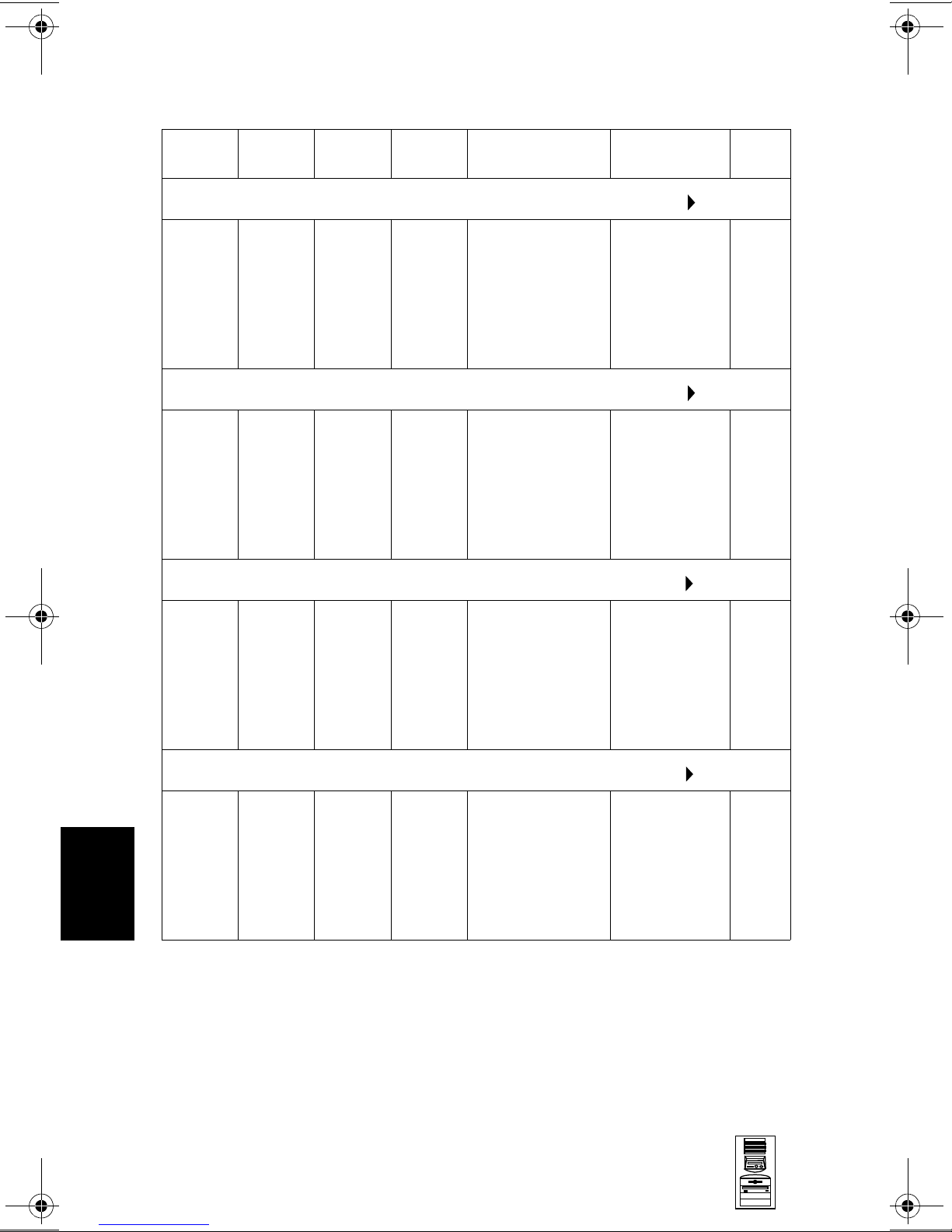
HP Kayak XA-s MT Series 02xx PC Workstation
Product
Number
D5759N Pentium
D5769N
and
D5769T
Cache
Memory
HP XA-s PC Workstation 6/400 (Series 0202) (CPL: 07/98 )
II with
512 KB
of L2
cache
memory
HP XA-s PC Workstation 6/400 (Series 0203) (CPL: 09/98 )
Pentium
II with
512 KB
of L2
cache
memory
HP XA-s PC Workstation 6/450 (Series 0241)(CPL: 09/98 )
Std.
RAM
64 MB
SDRAM
100 MHz
non-ECC
64 MB
SDRAM
100 MHz
non-ECC
Hard
Drive
6.5 GB
Ultra
ATA
6.5 GB
Ultra
ATA
Video Controller Multi-media LAN
Matrox
Productiva G100
8 MB video
memory fitted.
Not upgradable.
Matrox
Millennium G200
8 MB SGRAM
on board,
upgradable to
16 MB SGRAM.
32✕ Max IDE
CD-ROM.
Audio chip
(AD1816) is
integrated on
the system
board.
32✕ Max IDE
CD-ROM.
Audio chip
(AD1816) is
integrated on
the system
board.
None
None
8
D5762N
and
D5762T
D5764N
and
D5764T
Pentium
II with
512 KB
of L2
cache
memory
HP XA-s PC Workstation 6/450 (Series 0262) (CPL: 03/99 )
Pentium
II with
512 KB
of L2
cache
memory
128 MB
SDRAM
100 MHz
non-ECC
128 MB
SDRAM
100 MHz
ECC
9.1 GB
SCSI
9.1 GB
SCSI
ELSA GLoria
Synergy AGP,
8 MB on board,
not upgradable.
Accel Galaxy AGP.
31 MB of video
memory. Not
upgradable.
32✕ Max IDE
CD-ROM.
Audio chip
(AD1816) is
integrated on
the system
board.
32✕ Max IDE
CD-ROM.
Audio chip
(AD1816) is
integrated on
the system
board.
10BT/
100TX
10BT/
100TX
8-2 HP Kayak XA-s MT Series 02xx PC
Workstation
Mini-Tower
PC Workstations
Page 4

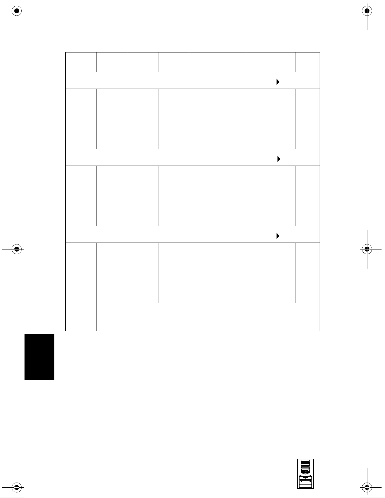
HP Kayak XA-s MT Series 02xx PC Workstation
Product
Number
HP Kayak XA-s PC Workstation 7/450 (Series 0203) (CPL: 03/99 )
D7981N
and
D7981T
D7983N
and
D7983T
Cache
Memory
Pentium
III with
512 KB
of L2
cache
memory
HP XA-s PC Workstation 7/500 (Series 0262) (CPL: 03/99 )
Pentium
III with
512 KB
of L2
cache
memory
Std.
RAM
HP Kayak XA-s 7/xxx PC Workstation
128 MB
SDRAM
100 MHz
ECC
128 MB
SDRAM
100 MHz
ECC
Hard
Drive
10.1 GB
Ultra
ATA
9.1 GB
SCSI
Video Controller Multi-media LAN
Millennium G200
8 MB SGRAM
on board,
upgradeable to
16 MB SGRAM
Accel Galaxy AGP.
31 MB of video
memory. Not
upgradable.
32✕ Max IDE
CD-ROM.
Audio chip
(AD1816) is
integrated on
the system
board.
32✕ Max IDE
CD-ROM.
Audio chip
(AD1816) is
integrated on
the system
board.
10BT/
100TX
None
D7984N
and
D7984T
D7995N
and
D7995T
HP XA-s PC Workstation 7/500 (Series 0241) (CPL: 03/99 )
Pentium
III with
512 KB
of L2
cache
memory
HP XA-s PC Workstation 7/500 (Series 0203) (CPL:06/99 )
Pentium
III with
512 KB
of L2
cache
memory
128 MB
SDRAM
100 MHz
ECC
128 MB
SDRAM
100 MHz
ECC
9.1 GB
SCSI
10.1 GB
Ultra
ATA
ELSA GLoria
Synergy AGP,
8 MB on board,
not upgradable.
Millennium G200
8 MB SGRAM
on board,
upgradeable to
16 MB SGRAM
32✕ Max IDE
CD-ROM.
Audio chip
(AD1816) is
integrated on
the system
board.
32✕ Max IDE
CD-ROM.
Audio chip
(AD1816) is
integrated on
the system
board.
10BT/
100TX
None
8
Mini-Tower
PC Workstations
HP Kayak XA-s MT Series 02xx PC
Workstation 8-3
Page 5
HP Kayak XA-s MT Series 02xx PC Workstation
Product
Number
D7889N
and
D7889T
D7988N
and
D7988T
Cache
Memory
HP XA-s PC Workstation 7/550 (Series 0262) (CPL: 0799 )
Pentium
III with
512 KB
of L2
cache
memory
HP XA-s PC Workstation 7/550 (Series 0241) (CPL: 07/99 )
Pentium
III with
512 KB
of L2
cache
memory
HP XA-s PC Workstation 7/600 (Series 0241) (CPL: 0799 )
Std.
RAM
128 MB
SDRAM
100 MHz
ECC
128 MB
SDRAM
100 MHz
ECC
Hard
Drive
9.1 GB
SCSI
9.1 GB
SCSI
Video Controller Multi-media LAN
Accel Galaxy AGP.
31 MB of video
memory. Not
upgradable
ELSA GLoria
Synergy AGP,
8 MB on board,
not upgradable
32✕ Max IDE
CD-ROM.
Audio chip
(AD1816) is
integrated on
the system
board.
32✕ Max IDE
CD-ROM.
Audio chip
(AD1816) is
integrated on
the system
board.
10BT/
100TX
10BT/
100TX
8
D7992N
and
D7992T
D6241AV
Pentium
III with
512 KB
of L2
cache
memory
Base Model. All models are ordered with optional components (such as,
processor, SDRAM memory modules, hard disk drives, graphic controller,
etc.).
128 MB
SDRAM
100 MHz
ECC
10.1 GB
Ultra
ATA
ELSA GLoria
Synergy AGP,
8 MB on board,
not upgradable
32✕ Max IDE
CD-ROM.
Audio chip
(AD1816) is
integrated on
the system
board.
None
8-4 HP Kayak XA-s MT Series 02xx PC
Workstation
Mini-Tower
PC Workstations
Page 6
HP Kayak XA-s MT Series 02xx PC Workstation
Supported Accessories
SDRAM 32MB 64bit 100MHz main memory (non-ECC) D6501A
SDRAM 64MB 64bit 100MHz main memory (non-ECC) D6502A
SDRAM 128MB 72bit 100MHz main memory (non-ECC) D6503A
SDRAM 64MB 72bit 100MHz main memory (unbuffered ECC) D6522A
SDRAM 128MB 72bit 100MHz main memory (unbuffered ECC) D6523A
SDRAM 256MB 72bit 100MHz main memory (unbuffered ECC) D6743A
Documentation
User’s Guide Manual D5760A
Input Devices
HP standard keyboard C4725A
HP mouse C3751B
HP mouse with scrolling wheel C4736A
Video Displays
All current HP PC Displays (refer to the Displays section of the Vectra
Accessory Service Handbook)
Mass Storage
4.3-GB 5400rpm Ultra ATA hard disk D2677A
6.5-GB 7200rpm Ultra ATA hard disk D6693A
4.5-GB 7200rpm Ultra SCSI hard disk D5368B
9.1 GB UW-SCSI hard disk 10k rpm
32✕ Max IDE CD-ROM drive D4384A
Atapi 100 MB Zip Drive D6650A
Processor Upgrades
Intel Pentium II 333 MHz containing 512 KB internal L2 cache D6526A
Intel Pentium II 350 MHz containing 512 KB internal L2 cache D6527A
Intel Pentium II 400 MHz containing 512 KB internal L2 cache D6528A
Intel Pentium II 450 MHz containing 512 KB internal L2 cache D6529A
Intel Pentium III
Intel Pentium III 500 MHz containing 512 KB internal L2 cache D7511A
Intel Pentium III 550 MHz containing 512 KB internal L2 cache D7512A
Intel Pentium III 600 MHz containing 512 KB internal L2 cache D7516A
2
3
450 MHz containing 512 KB internal L2 cache
1
D6520A
D7510A
8
1. 10k rpm hard disk drives can only be installed in the two upper internal disk drive shelves.
They must
2. Dual Processor Kits include: processor, voltage regulator module and heatsink.
3. In a dual-processor system, do not mix a Pentium III 450 MHz processor with a
Pentium II 450 MHz processor.
Mini-Tower
PC Workstations
not be installed in the lower front-access shelves.
HP Kayak XA-s MT Series 02xx PC
Workstation 8-5
Page 7
HP Kayak XA-s MT Series 02xx PC Workstation
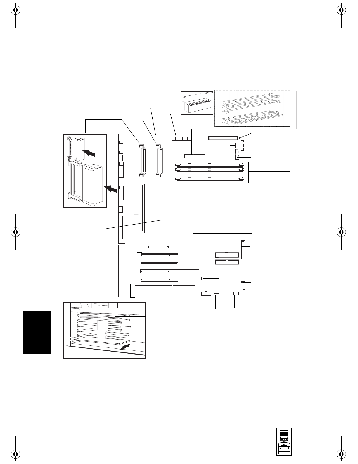
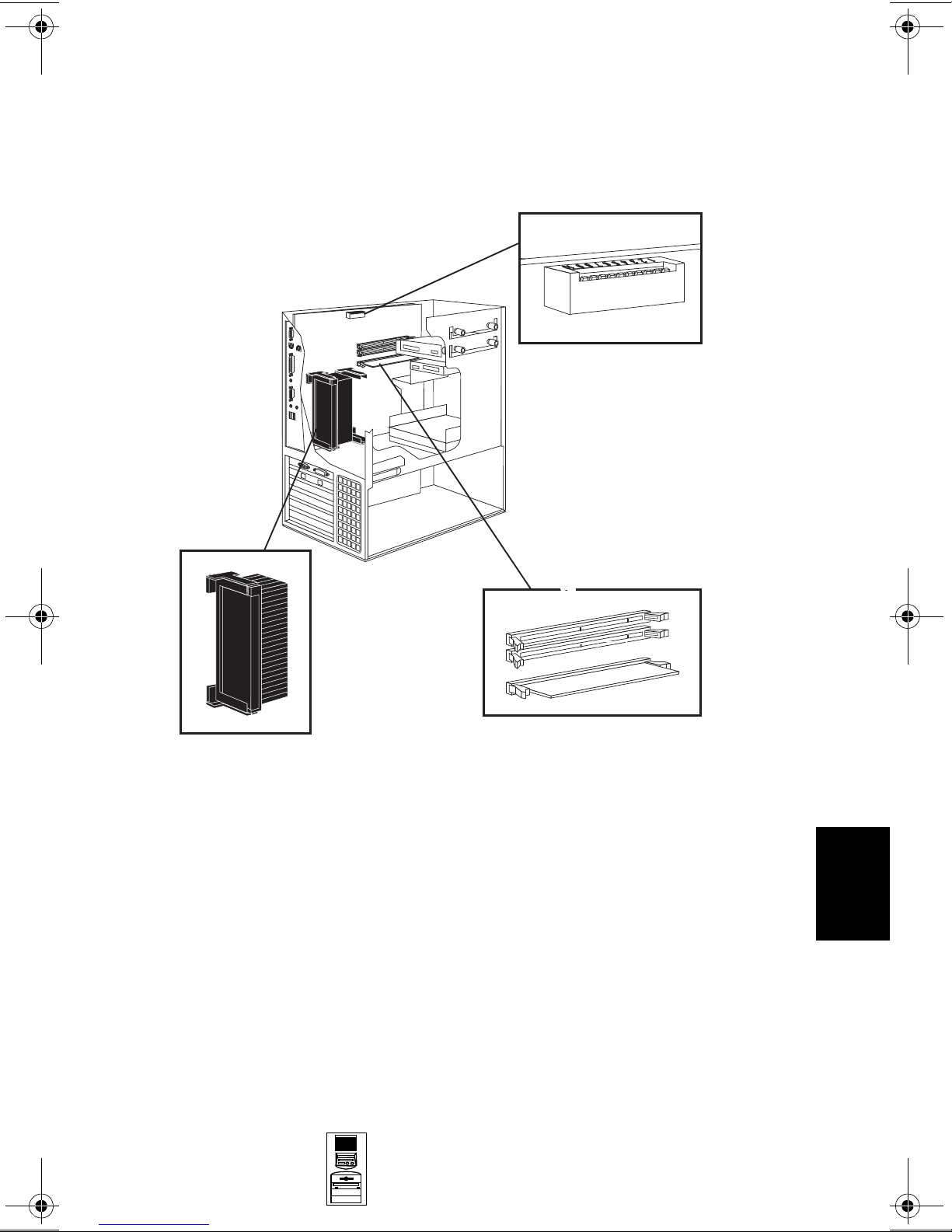
System Board, BIOS, and Memory
VRM 1
Processor 1
Processor 2
AGP Slot
PCI Slots
Processor Fan
VRM 2
Power
Switches
n
w
o
D
Up
FDD
External Battery
Memory Modules
Disk Drive Fan
On/Off Status
Panel
LCD Status Panel
4
3
1
External Start
Wake On LAN
Not used
IDE 2 Connector
IDE 1 Connector
8
ISA Slots
Video Board
8-6 HP Kayak XA-s MT Series 02xx PC
Workstation
I/O Fan
Mic In
Multimedia (jacks) panel
CD In Audio
Mini-Tower
PC Workstations
Internal Speaker
AUX
Page 8
HP Kayak XA-s MT Series 02xx PC Workstation
System Board Switches:
See the table on the next page.
p
U
n
w
o
D
Processor:
Pentium II module with
integrated heatsink, level-1 and
level-2 cache memory.
Mini-Tower
PC Workstations
Main Memory:
3 sockets (socket B is not available)
8
HP Kayak XA-s MT Series 02xx PC
Workstation 8-7
Page 9
HP Kayak XA-s MT Series 02xx PC Workstation
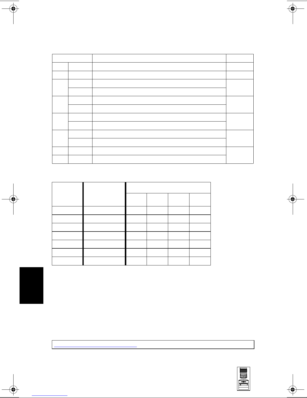
System Board Switches
Switch Function Default
1
1Up
2-5 - Processor frequency, see the following table -
Up Retains Configuration
6
Down Clears CMOS (to reload the Setup program defaults)
Up Enables passwords
7
Down Clears passwords
Up Disables keyboard power-on
8
Down Enables keyboard power-on (normal operation)
Up Minitower
9
Down Desktop
10 Up Enables normal mode
Down Enables Boot recovery mode
1. Up=Off, Down=On.
Reserved Up
Up
Up
Down
Up
Up
8
Processor
Frequency
333 MHz 66 MHz Up
350 MHz 100 MHz Up
400 MHz 100 MHz Up
450 MHz 100 MHz Up
500 MHz 100 MHz Up
550 MHz 100 MHz Up Down Down Up
600 MHz 100 MHz Up Down Down Up
1. FSB = Front Side Bus
2. For processors that are 500 MHz and higher, the frequency is
imposed.
Local Bus
Frequency
(FSB)
1
2345
Switch
Down Down Up
Up Down Down
Down Up Up
Down Up Down
Down Down Up
2
2
2
BIOS History
For the latest BIOS, the flasher utility program, and the BIOS history refer to the
HP World Wide Web site. The BIOS is in the form HK11yyzz
yy= BIOS version number
zz = is the selected language to be downloaded
http://www.hp.com/go/kayaksupport
8-8 HP Kayak XA-s MT Series 02xx PC
Workstation
Mini-Tower
PC Workstations
Page 10

HP Kayak XA-s MT Series 02xx PC Workstation
Installing a Dual Processor / Replacing a Processor
HP Kayak XA-s PC Workstations are supplied with dual processor slots and
either one or two processors installed. Single processor models can be
upgraded to dual processor systems by installing the second processor
accessory in the vacant slot.
The second processor must be a processor of the same type, speed and level-2
cache memory capacity as the first. It is installed by gently sliding the processor
into the vacant processor connector slot until the two plastic clips at the sides
engage to lock the processor into place.
Every processor that is installed, or replaced, must be accompanied by the
voltage regulator module (VRM) that was supplied with it. Each VRM is specific
to the processor with which it was supplied, and should only be used with that
processor.
NOTE: After installation of a second processor, the operating
system must be reinstalled.
The following tables explain how to perform supported processor upgrades. If
you need to install or upgrade to a Pentium III processor, refer to Table II on the
following page.
Tab le I - Pentium II Processor Upgrades
Dual Processor Upgrade
2x333 MHz
(D6526A)
nd
Pentium II
1x333 MHz
(D6526A)
Pentium II
1x350 MHz
(D6527A)
Pentium II
1x400 MHz
(D6528A)
Pentium II
1x450 MHz
(D6529A)
1. Switch settings must be changed. Ensure that the latest BIOS version has been installed.
2. Supplied processor must be removed.
Add 2
D6526A
1
2x350 MHz
(D6527A)
Remove
333 MHz
Add 2 x D6527A
Add 2
2
nd
D6527A1Remove
2x400 MHz
(D6528A)
Remove
333 MHz
1
Add 2 x D6528A
350 MHz
Add 2 x D6528A
nd
Add 2
2x450 MHz
(D6529A)
2
2
D6528A1Remove
Remove
333 MHz
1
Add 2 x D6529A
Remove
350 MHz
1
Add 2 x D6529A
400 MHz
Add 2 x D6529A
nd
Add 2
2
2
2
D6529A
1
1
1
1
8
Mini-Tower
PC Workstations
HP Kayak XA-s MT Series 02xx PC
Workstation 8-9
Page 11

HP Kayak XA-s MT Series 02xx PC Workstation
Table II - Pentium II to Pentium III Processor Upgrades
Dual Processor Upgrade
Pentium II
1x333 MHz
(D6526A),
1x350 MHz
(D6527A),
1x400 MHz
(D6528A)
Pentium II
1x450 MHz
(D6529A)
Pentium III
1x450 MHz
(D7510A)
Pentium III
1x500 MHz
(D7511A)
Pentium III
1x550 MHz
(D7512A)
Pentium III
1x600 MHz
(D7516A)
Pentium II
2x450 MHz
(D6529A)
refer to
Table I Pentium II
Processor
Upgrades
on the
previous
page
nd
Add 2
D6529A
2
N/A Add 2nd
N/A Add 2nd
Pentium III
2x450 MHz
(D7510A)
Remove
processor
Add 2 x
2
D7510
Remove
D6529A
3
Add 2 x
D7510A
2
Pentium III
1
2x500 MHz
Remove
3
.
processor
Add 2 x
D7511A
Remove
D6529A
Add 2 x
D7511A
(D7511A)
2
3
2
Remove
D7510A
2
D7510A
3
Add 2 x
D7511A
D7511A
2
2
N/A Add 2
N/A Add 2nd
Pentium III
Remove
3
processor
Add 2 x
D7512A
Remove
D6529A
Add 2 x
D7512A
Remove
D7510A
Add 2 x
D7512A
Remove
D7511A
Add 2 x
D7512A
D7512A
2x550 MHz
(D7512A)
nd
Pentium III
2x600 MHz
(D7516A)
Remove
3
processor
3
Add 2 x
2
D7516A
2
Remove
3
D6529
3
Add 2 x
2
D7516A
2
Remove
3
D7510A
3
Add 2 x
2
D7516A
2
Remove
3
D7511A
3
Add 2 x
2
2
D7516A
Remove
D7512A
2
3
Add 2 x
D7516A
D7516A
2
2
1. DO NOT MIX a Pentium II 450 MHz processor (D6529A) with a Pentium III 450 MHz
processor (D7510A).
2. Switch settings must be changed. Ensure that the latest BIOS version has been installed.
8
3. Supplied processor must be removed.
8-10 HP Kayak XA-s MT Series 02xx PC
Workstation
Mini-Tower
PC Workstations
Page 12

HP Kayak XA-s MT Series 02xx PC Workstation
Main Memory
The PC Workstation has three DIMM slots on the system board for installing
main memory. Models are supplied with 64 MB or 128 MB of main memory.
Memory upgrades are available in single 32 MB 64 MB, 128 MB and 256 MB ECC
unbuffered or non-ECC SDRAM modules.
Memory can be upgraded to a maximum of 768 MB using multiples of
(3 x 256 MB) of unbuffered or non-ECC SDRAM memory modules. A serial
EEPROM on each DIMM contains data on the memory speed. This information
is read at each power on, and access time settings are set accordingly.
Video Memory
The graphics controller installed on the PC Workstation could be either a
Matrox Productiva G100, a Matrox Millennium G200, an Accel Galaxy AGP, an
ELSA Gloria Synergy+™ or ELSA Gloria Synergy II.
The Matrox Productiva G100 has a total of 8 MB of video memory already
supplied on the graphics controller board which cannot be upgraded.
The Matrox Millennium G200 has a 8 MB of SGRAM memory already supplied
on the graphics controller board. Memory may be upgraded to a maximum of 16
MB by installing a 8 MB SGRAM memory module of onto the board.
The Accel Galaxy AGP Graphics card has 31 MB of video memory already
supplied on the graphics controller board, which cannot be further upgraded.
This card is supported only on the Windows NT operating system. Drivers do
not exist for Windows 95 nor Windows 98 operating systems.
The ELSA Gloria Synergy+ includes 8 MB of video SGRAM memory installed on
the graphics board and cannot be upgraded.
The ELSA Gloria Synergy II includes 32 MB of video SGRAM memory installed
on the graphics board and cannot be upgraded.
8
Mini-Tower
PC Workstations
HP Kayak XA-s MT Series 02xx PC
Workstation 8-11
Page 13

HP Kayak XA-s MT Series 02xx PC Workstation
Identifying the LAN/SCSI Combination Board
On HP Kayak XA-s models with the LAN/SCSI combination board, one of two
types of the HP 10/100 SCSI/LAN combination board are installed.
Both LAN/SCSI combination boards have the same functionalities, but there are
some minor differences. Due to this reason, when replacing one board by
another (refer to the note on page 15), caution should be taken to ensure you
have the correct board.
Most HP Kayak XA-s models introduced around 07/98 (CPL) were preinstalled
with the LAN/SCSI combination board (part number 5064-3616) that included
one internal wide SCSI connector. This board does not include a Wake On Lan
(WOL) connector. For the Remote Power On (RPO) feature to work, the
ExtStart cable is used to connect between the External Start connector on the
SCSI/LAN combination board and the HP External Start connector on the
system board.
While, on the most recently introduced Kayak XA-s models, the SCSI/LAN
combination board (part number 5064-6016), includes two SCSI connectors,
one wide and one narrow. However, the internal narrow SCSI connector is not
used on XA-s models (wide SCSI cable used). The SCSI/LAN combination board
also includes a Wake On Lan (WOL) connector. The RPO feature is now made
available through the WOL connector, and no longer through the HP External
Start connector. The HP External Start connector is still used to report LAN
activity and SCSI hard disk drive accesses to the front panel LEDs.
8
How to Identify Which LAN/SCSI Board is Installed
As mentioned earlier, there is no difference between the rear panels of the two
SCSI/LAN boards. To identify which board is installed, you have to check the
board for the above mentioned differences. To do that:
1 Shut down the PC Workstation, turn off the computer and disconnect the
power cable. Remove the cover.
2 Check the part number:
5064-6016 — Includes two internal SCSI connectors (wide and narrow) and
a WOL connector.
5064-3616 — Includes one internal SCSI connector. The WOL connector is
not available on this board.
If replacing one LAN/SCSI combination board model by the other model, refer
to the note on page 15, for instructions.
8-12 HP Kayak XA-s MT Series 02xx PC
Workstation
Mini-Tower
PC Workstations
Page 14

HP Kayak XA-s MT Series 02xx PC Workstation
Parts and Part Numbers
3
2a
1e
1k
1j
4
17
1f
1g
1h
1j
2b
1b
1
5
7
7 8
1c
6
15
17
14
Mini-Tower
PC Workstations
13
12
11
1d
1a
8
9
11
10
HP Kayak XA-s MT Series 02xx PC
Workstation 8-13
Page 15

HP Kayak XA-s MT Series 02xx PC Workstation
Parts List
8
Item Description Repl.
Part Number
1 Chassis assembly:
a I/O Guide + Fan + Speaker assembly
b Cover lock assembly
c LCD status panel kit
d Multimedia control panel
e 5.25-inch hard drive tray
f Filler panel 3.5-inch
g Filler panel 5.25-inch
h Multimedia bezel
i Hard Disk Drive Fan
j Processor airflow guide
k SCSI holder protection
Not shown:
I/O Panel
Bumper foot
2 Logos
a XA-s PC Workstation logo
b Hewlett-Packard logo
3 Hard disk drive (standard)
4.3 GB IDE 5400rpm D2677-63001 D2677-69001
6.4 GB IDE 7200rpm
4.5 GB SCSI 7200rpm
9.1 GB SCSI 10k rpm
9.1 GB Ultra SCSI 7.2k rpm
4.5 GB IDE 7200rpm D9796-63001 D9796-69001
10.1 GB IDE 7200rpm D9795-63001 D9795-69001
4 Power Supply Unit 0950-2893 —
5 Flexible disk drive (bezel-less)
6 CD-ROM drive (standard)
32x IDE
7 Rail kit (3.5-inch and 5.25-inch)
8 ATA/IDE cable kit
CD-ROM to audio cable 5182-1857 —
9
Headset (supported only on models
10
shipped before December, 1998)
1
5065-0499
5064-6055
5062-5590
5064-3683
5064-3383
5002-1946
5042-1405
5042-1178
5042-1873
5064-6054
5064-3674
5042-3014
45935-00004
5042-2479
5042-3022
5042-3030
D6452-63001 D6452-69001
D5145-63001 D5145-69001
D6451-63001 D6451-69001
D6455-63001 D6455-69001
D2035-60172 —
D4384-63001 D4384-69001
5063-7922 —
5064-6065 —
5064-2673 —
Exchange
Part Number
—
—
—
—
—
—
—
—
—
—
—
—
—
—
—
8-14 HP Kayak XA-s MT Series 02xx PC
Workstation
Mini-Tower
PC Workstations
Page 16

HP Kayak XA-s MT Series 02xx PC Workstation
Parts List
Item Description Repl.
Part Number
11 Graphics board:
a Matrox Productiva G100 (8 MB)
b Not shown on previous page:
a Matrox Millennium G200 (8 MB)
b Accel Galaxy AGP (31 MB)
c Gloria Synergy +
d Gloria Synergy II
e Matrox Productiva G100-Quad
G100-Quad cable kit (2 Y-cables)
12 2-button mouse with scrolling wheel
Not shown:
HP 3-button mouse (only shipped with
models with the Accel Galaxy video board)
13 CPU holder
14 System board
15 Flexible disk drive cable
16 Processor Terminator
17 Processor retainer airflow guide
Not
Shown
Enhanced Keyboard
Screw 6-32 auto-guiding (long)
Serial number label
SCSI cable (16-bit data) for SCSI models
only
a HP 10/100 BT SCSI/PCI LAN Board
10/100 BT SCSI/PCI LAN Board
a Internal LAN-to-CPU cable
b WOL cable
c Internal LAN-to-CPU cable
D5756-63501
5064-7478
5064-7457
5064-6732
5064-9794
5064-7427
5183-9475
C4736-60101
C4728-60101
5042-1162 —
See PC’s system board parts list
5183-0746 —
5064-6722 —
5042-3013 —
C4734-603xx
2680-0311 —
5182-0030 —
5183-2702 —
3
HP
5064-3616
5064-6016
5183-2786
5183-2769
5183-6090
Part Number
D5756-69501
D5685-69501
D6728-69501
D6478-69501
D7992-69501
D7980-69501
—
—
2
—
D5755-69001
D6331-69301
—
—
—
Exchange
1. For optional disk drive information, refer to the Accessories section of this Service
Handbook.
2. Where “xx” is the code for your national keyboard (refer to the Accessories
section of this Service Handbook).
3. If replacing the HP 10/100 BT SCSI/PCI LAN board 5064-3616 by the 5064-6016,
the WOL cable is required and the Internal LAN-to-CPU cable 5183-2786 is
replaced by the 5183-6090.
Mini-Tower
PC Workstations
8
HP Kayak XA-s MT Series 02xx PC
Workstation 8-15
Page 17

HP Kayak XA-s MT Series 02xx PC Workstation
System Board Parts List
Description Repl.
Part Number
System board:
XA-s 6/xxx system board D7981-60001 D5756-69001
Processors:
Intel Pentium II 333/512 5064-3697 —
Intel Pentium II 350/512 D6527-63001 D6527-69001
Intel Pentium II 400/512 D6528-63001 D6528-69001
Intel Pentium II 450 MHz, 512 KB cache D6529-63001 D6529-69001
Intel Pentium III 450 MHz, 512 KB cache D7510-63001 —
Intel Pentium III 500 MHz, 512 KB cache D7511-63001 —
Intel Pentium III 550 MHz, 512 KB cache D7512-63001 —
Intel Pentium III 600 MHz, 512 KB cache D7516-63001 —
Voltage Regulator module (VRM) 0950-2837 —
Main memory modules:
1 ✕ 32MB 100 MHz non-ECC SDRAM D6501-63001 —
1 ✕ 64MB 100 MHz non-ECC SDRAM D6502-63001 —
1 ✕ 64MB 100 MHz ECC SDRAM 1818-7140 D5365-69001
SDRAM 128MB 100 MHz non-ECC D6503-63001 D6503-69001
Exchange
Part Number
Manuals and Documentation
8
Description Part Number
User’s Guide D5760-90001 Paper document
Familiarization Guide D5699-90901 Electronic file
(PDF)
Technical Reference Manual: hardware and
BIOS
ConfigTailor CD-ROM 5011-6634 —
no number Electronic file
(PDF)
8-16 HP Kayak XA-s MT Series 02xx PC
Workstation
Mini-Tower
PC Workstations
Page 18

A
Beep, POST, and Error Codes
Beep Codes
If an error occurs during the POST, which prevents the PC Workstation from
starting, and before the display device has been initialized, a series of beep
codes are issued. Beep codes indicate that a fatal error has occurred and can be
reported one after another if there is more than one detected error. In this case,
the first detected error is the most important.
These codes are useful for identifying the error when the system is unable to
display the error message.
A
Beep, POST, and Error Codes A-1
Page 19

A
Beep Codes for the HP Kayak XU800
Number
of
Beeps
1 The memory refresh
2 Parity error in the base
3 Memory error.
4 Clock error. • Check that the system board is correctly
5 Processor test error. Check that:
Description Action to Take...
Check that:
circuitry is faulty.
memory (the first 64 KB
block) of memory.
• Memory is installed correctly.
• Correct memory modules are being used.
If the error still occurs, replace the memory.
cabled (power cables, processor and
terminator).
If the error still occurs, replace the system
board.
• Processor is correctly installed.
• Termination card installed in processor
slot 2 in a single processor system.
If the error still occurs, replace:
1Processor.
2 system board.
6 Input/Output (I/O) error. • Keyboard is connected.
• PCI card is installed correctly.
• Termination card installed in processor
slot 2 in a single processor system.
7 The processor on the
system board generated
an error.
8 The system video card is
either missing or faulty.
• There is an installed processor(s).
• Processor(s) is correctly installed in the
processor slot(s).
• Two installed processors have the same
cache size (256 k).
• Termination card is installed in processor
slot 2 in a single processor system.
• VRM is installed in the VRM socket in a
dual processor system.
If the error still occurs, replace the system
board.
This is not a fatal error. Check that the video
card is correctly installed and cabled. If
missing, install the video card. If the error
still occurs, replace it with a known working
video card.
A-2 Beep, POST, and Error Codes
Page 20

A
Number
of
Beeps
9 The BIOS Checksum
10 The CMOS RAM has
11 The cache memory test
Description Action to Take...
value does not match the
value encoded in the
BIOS.
failed.
failed.
Perform the following actions in this order:
1Press F2 to enter the Setup program,
then F9 to load the default BIOS settings.
2 Clear the CMOS.
3 Flash the BIOS.
If the error still occurs, replace the system
board.
Perform the following actions in this order:
1Press F2 to enter the Setup program,
then F9 to load the default BIOS settings.
2 Clear the CMOS.
3 Flash the BIOS.
If the error still occurs, replace the system
board.
Replace the processor(s).
Beep, POST, and Error Codes A-3
Page 21

A
Beep Codes for the HP Kayak XM600
Beep
Pattern
— - - - - - - -
— - - - — —
— - - - — - - -
— - - - - - - —
— - - - - - - - —
— - - - - - - - - - -
— - - - - — —
- - — - - - - -
- - - - - - - —
Beep
Code
1-2-2-3 16h
1-3-1-1 20h
1-3-1-3 22h
1-3-3-1 28h
1-3-4-1 2Ch
1-3-4-3 2Eh
1-4-1-1 30h
2-1-2-3 46h
2-2-3-1 58h
Numeric
Code
Description Recommended
Action
BIOS ROM
check-sum
failure
DRAM refresh
test failure1
8042
Keyboard
controller test
failure
Initialization
of RDRAM
has failed.
RAM failure
on address
1
....
line
RAM failure
on data bits
....of low byte
of memory
bus1
RAM failure
on data bits
....of high byte
of memory
bus1
ROM
copyright
notice check
failure
Unexpected
interrupts test
failure
Inform HP support/HP reseller
that system board is defective.
Check the memory is correctly
installed. If the error still occurs,
replace the module.
Inform HP support/HP reseller
that system board is defective.
Verify that memory or continuity
modules are installed.
Check the memory is correctly
installed. If the error still occurs,
replace the module.
Check the memory is correctly
installed. If the error still occurs,
replace the module.
Check the memory is correctly
installed. If the error still occurs,
replace the module.
Inform HP support/HP reseller
that system board is defective.
Inform HP support/HP reseller
that system board is defective.
— - -
1. Non-HP memory modules are not supported. Only HP memory modules should be used.
1-2 98h
A-4 Beep, POST, and Error Codes
Video
configuration
failure or
option ROMs
check-sum
failure
This can be caused by problems
with the ROM on integrated
video, an add-on video board or
the ROM on a SCSI card.
Inform reseller for the affected
component.
Page 22

POST and Error Codes
Beep Codes for Previous Models
The following beep codes are for all models before the HP Kayak XU800 and
XM600 PC Workstations.
A
Beep Pattern Beep
Code
— - - - - - - - 1-2-2-3 16h BIOS ROM check-sum failure
— - - - — — 1-3-1-1 20h DRAM refresh test failure
— - - - — - - - 1-3-1-3 22h 8742 Keyboard controller test failure
1-3-3-1 28h Autosize DRAM
1-4-4-1 30h RAM failure on data bits of high byte of
— - - - - - - - — 1-3-4-1 2Ch RAM failure on address line xxxx
— - - - - - - - - - - 1-3-4-3 2Eh RAM failure on data bits xxxx1 of low
- - — - - - - - 2-1-2-3 46h ROM copyright notice check failure
- - - - - - - — 2-2-3-1 58h Unexpected interrupts test failure
— - - 1-2 98h Video configuration failure or option
- 1 B4h /
- - - - - - - - - - - - - - - 4-2-4-4 Crisis recovery flash error
Numeric
Code
F4h
Description
memory bus
1
byte of memory bus
ROMs check-sum failure
This does not indicate an error. There is
one short beep before system startup.
2
1. If the BIOS detects error 2C or 2E (base 512K RAM error), it displays an additional wordbitmap (xxxx) indicating the address line or bits that failed. For example, “2C 0002” means
address line 1 (bit one set) has failed. “2E 1020” means data bits 12 and 5 (bits 12 and 5 set)
have failed in the lower 16 bits.
2. For more information, refer to Appendix B.
POST and Error Codes
A list of all POST (Power-On Self-Test) and error codes are available through
electronic files from the Support Center.
If you wish to view the POST details, press the key when the Kayak logo is
being displayed at power on, and the checkpoint code of the test currently in
progress will appear in the upper right corner of the screen. When POST is
completed, the HP Summary Screen will appear.
Beep, POST, and Error Codes A-5
Page 23

A
POST and Error Codes
Notes: ______________________________________________________________
____________________________________________________________________
____________________________________________________________________
____________________________________________________________________
____________________________________________________________________
____________________________________________________________________
____________________________________________________________________
____________________________________________________________________
____________________________________________________________________
____________________________________________________________________
____________________________________________________________________
____________________________________________________________________
____________________________________________________________________
____________________________________________________________________
A-6 Beep, POST, and Error Codes
Page 24

B
Recovery Boot Active Procedures
HP Kayak XU800 PC Workstation
BIOS Recovery
NOTE: The following BIOS recovery (Crisis Mode) is for the HP
Kayak XU800 PC Workstation models only.
If for some reason the BIOS is corrupted and the standard flash cannot be used,
use the BIOS Recovery Mode (exceptional BIOS recovery operation) to restore
the BIOS.
The following recovery operation is also documented in the flash.txt file which
is supplied with the downloaded BIOS files.
To restore the BIOS:
1 Copy the BIOS files on to the floppy disk.
B
2 Rename the file AI11xx.rom to amiboot.rom.
3 Shut down the PC Workstation.
4 Power off the PC Workstation and remove the power cord and cables.
5 Remove the cover.
6 Set switch 1 to the DOWN position.
7 Insert the floppy disk into the floppy disk drive.
8 Reconnect the power cord and switch on the PC Workstation.
9 The PC Workstation boots from the floppy disk, then flashes the BIOS.
However, it should be noted that during the flash process, the screen remains
blank. MaxiLife will display a message on the LCD panel “RECOVERY
MODE”.
10 The recovery process is finished when there are four beeps.
11 Power off the PC Workstation. Remove the floppy disk from the drive.
Remove the power cord.
12 Set switch 1 back to the UP position.
13 Replace the cover, reconnect the power cord, then reboot the PC
Workstation.
Recovery Boot Active Procedures B-1
Page 25

HP Kayak XM600 PC Workstation Desktop and
Minitower BIOS Recovery
B
NOTE: The following BIOS recovery (Crisis Mode) is for the HP
Kayak XM600 Desktop and Minitower PC Workstations
only.
If for some reason the BIOS is corrupted and the standard flash cannot be used,
use the BIOS Recovery Mode (exceptional BIOS recovery operation) to restore
the BIOS. To do this:
1 Obtain a bootable DOS floppy disk.
2 Copy the BIOS files on to the floppy disk.
The latest system BIOS (standard flash operation) can be downloaded from
HP’s Support Web site at: http://www.hp.com/go/kayaksupport. Then select
HP Kayak XM600 PC Workstation.
Instructions on updating the BIOS are supplied with the downloaded BIOS
files and a BIOS flash utility (flash.txt).
3 Create (or edit) the file, AUTOEXEC.BAT This should contain a single line of
text: “phlash /c /mode=3 IC1105US.FUL”
(rename the BIOS filename with the one on the floppy disk).
4 Shut down the PC Workstation.
5 Power off the PC Workstation and remove the power cord.
6 Remove the cover.
7 Set switch 7 to the ON position.
8 Insert the floppy disk into the floppy disk drive.
9 Reconnect the power cord and switch on the PC Workstation.
10 The PC Workstation boots from the floppy disk, then flashes the BIOS.
However, it should be noted, that during the flash process, the screen
remains blank.
11 The recovery process is finished when there is one very long beep.
12 Power off the PC Workstation. Remove the floppy disk from the drive.
Remove the power cord.
13 Set switch 7 back to the OFF position.
14 Replace the cover, reconnect the power cord, then reboot the PC
Workstation.
B-2 Recovery Boot Active Procedures
Page 26

Force BIOS flash, Switch 9 (XA models) or
10 (XW and XA-s models) Down Position
WARNING: WARNING: For Kayak XU Series 03xx, XA-s Series
02xx and XA Series 05xx, a specific ‘Mini-Dos’
bootable disk has to be used. An image of this
‘Mini-Dos’ bootable floppy can be obtained from
the Alps/Info server (not available from the
external web site). If you do not have access to the
Alps/Info server, contact your escalation team.
If, for example, during a BIOS flash, the procedure is interrupted by a power
failure, and the system does not restart, then you can force a BIOS flash.
However, it should be noted that during the procedure, there is no image on the
screen, nor access to the keyboard or mouse (only “vital” devices that are
required to boot on the floppy device are initialized).
To force a BIOS flash, do the following steps:
1 Ensure that you have created a DOS-bootable diskette. This floppy diskette
contains all the recovery and system BIOS programming software
(phlash.exe, platform.bin and hb1xxxyy.Ful). Include the flash command in
the autoexec.bat, for example: phlash /mode=3 hb1xxxyy.Ful
2 Turn off the computer.
B
3 Set Switch 9 (XA models) or,
Set Switch 10 (XW, XU and XA-s models) to the DOWN position (=on).
4 Insert the DOS-bootable diskette (refer to the above warning).
5 Power on the computer.
6 During the recovery process, short beeps are emitted. The recovery process
is finished when there is a much longer beep (approximately around 1 to 2
minutes).
7 Power off the computer. Press the power ON/OFF button (for about 5
seconds), until the ON/OFF light switches off. Set the switch 10 to the UP
position (=off).
Recovery Boot Active Procedures B-3
Page 27

B
Notes: ______________________________________________________________
____________________________________________________________________
____________________________________________________________________
____________________________________________________________________
____________________________________________________________________
____________________________________________________________________
____________________________________________________________________
____________________________________________________________________
____________________________________________________________________
____________________________________________________________________
____________________________________________________________________
____________________________________________________________________
____________________________________________________________________
____________________________________________________________________
B-4 Recovery Boot Active Procedures
 Loading...