

Page 1
Familiarization Guide
HP Kayak XA Series
0503 and 0541 PC Workstation
This guide is for experienced technicians who have already completed the HP
Kayak PC family training course. It assumes that the reader is already familiar with
the different HP Kayak models.
This document is a self-paced familiarization guide designed to train you to repair
the PC. It contains information specific only to the repair of the HP Kayak XA
Series 0503 and 0541 Desktop and Minitower PC Workstations with the HP
MaxiLife feature.
For information on the installation of accessories, refer to the paper User’s Guide
and the online documents that are supplied with the PC.
To access the HP World-Wide Web support site:
http://www.hp.com/go/kayaksupport
Page 2

Notice
The information contained in this document is subject to change without
notice.
Hewlett-Packard makes no warranty of any kind with regard to this
material, including, but not limited to, the implied warranties of
merchantability and fitness for a particular purpose.
Hewlett-Packard shall not be liable for errors contained herein or for
incidental or consequential damages in connection with the furnishing,
performance, or use of this material.
Hewlett-Packard assumes no responsibility for the use or reliability of its
software on equipment that is not furnished by Hewlett-Packard.
This document contains proprietary information that is protected by
copyright. All rights are reserved. No part of this document may be
photocopied, reproduced, or translated to another language without the
prior written consent of Hewlett-Packard Company.
ELSA
Aachen and/or ELSA Inc., Santa Clara.
Matrox® is a registered trademark of Matrox Electronics Systems Ltd.
Microsoft®, Windows® and MS-DOS® are registered trademarks of the
Microsoft Corporation.
WOL™
Windows NT
®
and GLoria Synergy® are registered trademarks of ELSA AG,
(Wake On LAN) is a trademark of IBM.
® is a registered trademark of Microsoft Corporation.
Hewlett-Packard France
38053 Grenoble Cedex 9
France
1998 Hewlett-Packard Company
Page 3

Contents
Notice. . . . . . . . . . . . . . . . . . . . . . . . . . . . . . . . . . . . . . . . . . . . . . . . . . . . 2
HP Kayak PC Workstation Overview. . . . . . . . . . . . . . . . . . . . . . . . . . 5
Identifying the Latest Kayak XA PC Workstation . . . . . . . . . . . . . . . 7
HP Kayak PC Workstation Package. . . . . . . . . . . . . . . . . . . . . . . . . . . 8
Desktop . . . . . . . . . . . . . . . . . . . . . . . . . . . . . . . . . . . . . . . . . . . . . . . . . 8
Minitower . . . . . . . . . . . . . . . . . . . . . . . . . . . . . . . . . . . . . . . . . . . . . . . . 9
System Board Layout. . . . . . . . . . . . . . . . . . . . . . . . . . . . . . . . . . . . . . 10
System Board Layout. . . . . . . . . . . . . . . . . . . . . . . . . . . . . . . . . . . . . . 10
System Board Switches. . . . . . . . . . . . . . . . . . . . . . . . . . . . . . . . . . . . 11
Removing and Replacing the Cover. . . . . . . . . . . . . . . . . . . . . . . . . . 12
On Desktop Models . . . . . . . . . . . . . . . . . . . . . . . . . . . . . . . . . . . . . . . 12
On Minitower Models. . . . . . . . . . . . . . . . . . . . . . . . . . . . . . . . . . . . . . 13
Removing and Replacing the Power Supply Unit . . . . . . . . . . . . . . 14
On Desktop Models . . . . . . . . . . . . . . . . . . . . . . . . . . . . . . . . . . . . . . . 14
On Minitower Models. . . . . . . . . . . . . . . . . . . . . . . . . . . . . . . . . . . . . . 15
Power Supply Unit . . . . . . . . . . . . . . . . . . . . . . . . . . . . . . . . . . . . . . . . 16
HP MaxiLife Utility. . . . . . . . . . . . . . . . . . . . . . . . . . . . . . . . . . . . . . . . 17
Error Messages . . . . . . . . . . . . . . . . . . . . . . . . . . . . . . . . . . . . . . . . . . 18
Running the MaxiLife Diagnostics Program. . . . . . . . . . . . . . . . . . . 21
Checking the System Configuration . . . . . . . . . . . . . . . . . . . . . . . . . 22
Checking the Display Screen . . . . . . . . . . . . . . . . . . . . . . . . . . . . . . . 23
Upgrading Main Memory Modules. . . . . . . . . . . . . . . . . . . . . . . . . . . 25
English 3
Page 4

Identifying Video Boards on an HP Kayak XA . . . . . . . . . . . . . . . . . 26
Connecting Devices on the SCSI/LAN Combination Board . . . . . . 27
Flashing the Latest Version of the System BIOS . . . . . . . . . . . . . . . 28
Complete the Questionnaire
to Check Your Understanding. . . . . . . . . . . . . . . . . . . . . . . . . . . . . . . 29
Answers and Explanations . . . . . . . . . . . . . . . . . . . . . . . . . . . . . . . . . 32
Electrostatic Discharge Warning . . . . . . . . . . . . . . . . . . . . . . . . . . . . 35
4 English
Page 5
HP Kayak PC Workstation Overview
HP Kayak PC Workstation Overview
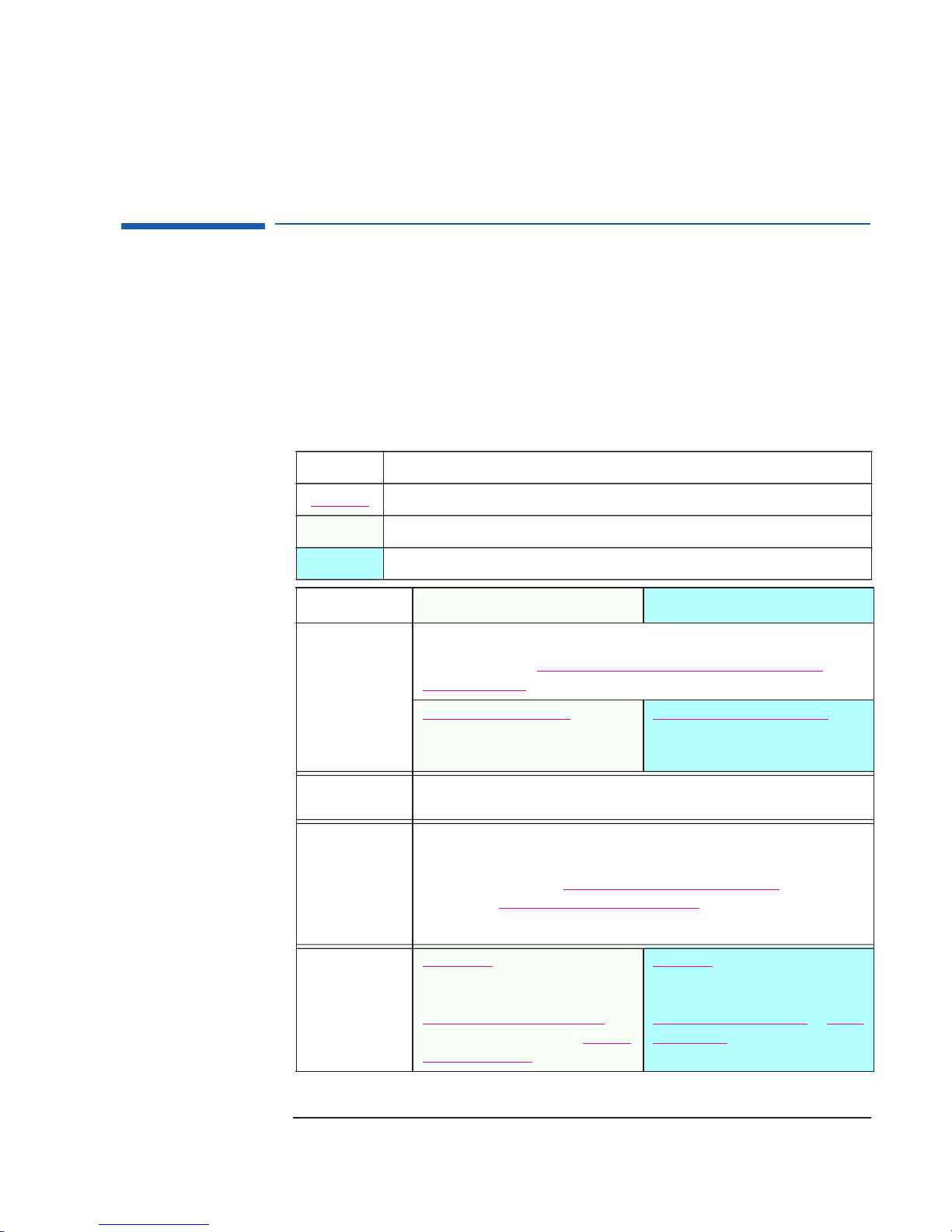
The following table provides an overview of the HP Kayak XA Series 0503
and 0541 Desktop and Minitower PC Workstations.
®
HP Kayak XA Series 0503 PC Workstations contain the Matrox
Millennium G200 video board, while the HP Kayak XA Series 0541 PC
Workstations are installed with the ELSA
®
GLoria Synergy+® video board.
How to use the table:
Component is common to more than one model.
underlining
Component
Microprocessor
External
Processor Bus
(Front Side Bus)
Operating System
Main Memory
A new feature (compared with previous HP Kayak XA models) is highlighted by underlining.
Component is available only on HP Kayak XA Minitower PC Workstations.
Component is available only on HP Kayak XA Desktop PC Workstations.
XA Minitower Models XA Desktop Models
All models include:
®
Intel
Pentium II for Deschutes Slot 1 processor with 512 KB cache memory.
Single processor slot
400, 450 MHz: 100 MHz FSB 350, 400, 450 MHz: 100 MHz FSB
All models are supplied with a 64 MB non ECC SDRAM memory module.
Three DIMM sockets supporting:
32 MB, 64 MB, 128 MB or 256 MB Unbuffered 100 MHz ECC SDRAM
a maximum of 768
Note: Registered ECC SDRAM memory modules are not supported.
.
®
All models are preloaded with Windows
Windows 95 and Windows 98 are also supported.
MB (using multiples of 3 x 256 MB).
NT 4.0.
and non-ECC to
Mass Storage
Seven shelves: Five front-access (two
3½-inch, three 5¼-inch); two internal
3½-inch.
Ultra ATA 33 6.4 GB (7.2 krpm) IDE
disk drives, or on some models 9.1 Ultra-
Wide SCSI (7.2 krpm) hard disk drives.
hard
Five shelves: Three front-access drives
(one 3½-inch), two 5¼-inch; two
internal 3½-inch
Ultra ATA 33 4.3 GB (5.4 krpm
(7.2 krpm) IDE hard disk drives.
1
.
) or 6.4 GB
5
Page 6
HP Kayak PC Workstation Overview
Component
SCSI Connectors
(available on
some models)
Video Boards
Accessory Board
Slots
Communications
CD-ROM Drive
XA Minitower Models XA Desktop Models
Ultra-Wide 16-bit SCSI connector for both
None.
external and internal SCSI devices (up to
40 MB per second)2.
XA Series 0503 models are equipped with a Matrox
® Millennium G200 AGP video
board. There is a 8 MB SGRAM video memory. The video memory is upgradeable to
16 MB by installing 4 MB SO-DIMM (SGRAM) video memory modules.
XA Series 0541 models are equipped with an ELSA GLoria Synergy+
™ AGP video
board. There is a 4 MB SGRAM video memory. Added to this, there is a preinstalled 4
MB SO_DIMM (SGRAM) video memory module. This gives a total of 8 MB of installed
video memory which cannot be upgraded.
All models have 6 slots: 1 AGP, 3 PCI, 1 ISA, 1 combination ISA/PCI.
3
Support for WOL
1 PCI slot (slot 4) used for the LAN/UltraWide SCSI board with RPO capability.
compatible LAN boards.
1 AGP slot used for the Video Adapter.
1 audio board.
1 AGP slot used for the Video Adapter.
1 audio board.
All models have 2 USB (A, B) connectors, 2 serial ports, 1 parallel port
All models include a 32X speed IDE CD-ROM
Audio
HP MaxiLife
Utility (available
on all models)
All models are preinstalled with an audio board, including: integrated 16-bit hi-fi full
duplex stereo, Sound Blaster compatibility and standard built-in audio features.
Hardware monitoring utility that monitors system components (for example: if you are
unable to get the system and display working properly). When an error is detected it is
displayed on the dedicated LCD located on the front panel.
Input voltage:
100-127, 200-240V
(manual switch select)
Input frequency:
Maximum power:
50/60Hz
200 W continuous
Power Supply
Note: Even though the first shipments of HP Kayak Series 05xx PC Workstations
included a 260 W power supply unit (automatic switch select), all subsequent models
are shipped with a 200 W power supply unit. PC Workstations with a 200 W power
supply do not support accessory boards that require a large amount of power.
1.
The internal drive housing can support one 1” and one 1.6” high hard disk drive, or
two 1” hard disk drives.
2.
Available on some models only.
Refer to the HP Kayak Service Handbook for Models and Accessories list.
3.
WOL = Wake On LAN.
6
Page 7
Identifying the Latest Kayak XA PC Workstation
Identifying the Latest Kayak XA PC Workstation
How can I tell the difference between the latest HP Kayak XA model
(series 0503 or 0541), and the previous HP Kayak XA models?
There are two simple and quick ways to identify the latest HP
Kayak XA model. First, there is a label on the side of the PC
indicating “Series 0503” or “Series 0541”. Second, the latest
Kayak XA models are equipped with a single Pentium II
Deschutes processor for Slot 1.
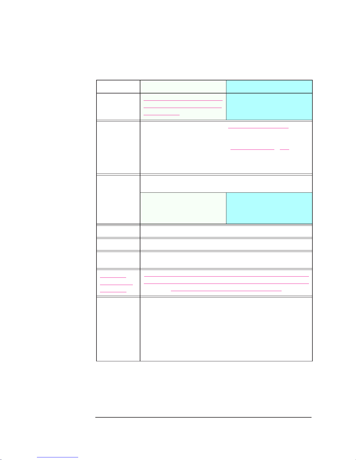
As well as the above-mentioned differences, there are a number of other
differences between the HP Kayak XA Series 0503 and 0541 and previous
XA models, and these are shown in the table below.
Component
Processor and
Frequency Speeds
Chipset
Cache
Memory
Video Board
Audio Board
BIOS
Hardware
Monitoring
HP Kayak XA Series 0502 and 0503
Introduced October ‘98
Single Pentium II Deschutes processor for Slot 1 with an
operating frequency of 350 MHz, 400 MHz or 450 MHz
on a 100 MHz system bus. The processor includes an
integrated heatsink, level-1 and level-2 cache memory.
Intel 440BX/PIIX4E Intel 440LX/PIIX4
512 KB 256 KB or 512 KB
Three DIMM sockets giving a maximum total of 768 MB Three DIMM sockets giving a maximum total of 384 MB.
Matrox Millennium G200 with 8 MB of SGRAM video
memory. Upgradeable to 16 MB.
Elsa GLoria Synergy+
installed SGRAM video memory, which cannot be
upgraded.
Installed in an ISA accessory slot. AD1816 audio chip integrated on the system board.
ACPI BIOS. —
HP MaxiLife with LCD status panel. Limited hardware monitoring.
™
video board with 8 MB of
Single Pentium II Klamath processor for Slot 1 with an
operating frequency of 233 MHz, 266 MHz or 300 MHz
on a 66 MHz system bus. The processor includes an
integrated heatsink, level-1 and level-2 cache memory.
Integrated 2 MB Cirrus AGP video memory soldered on
the system board, with a further 2MB in a module,
giving 4 MB in total.
HP Kayak XA Models
Introduced October ‘97
ASIC
HP MaxiLife. Little Ben.
7
Page 8
HP Kayak PC Workstation Package
HP Kayak PC Workstation Package
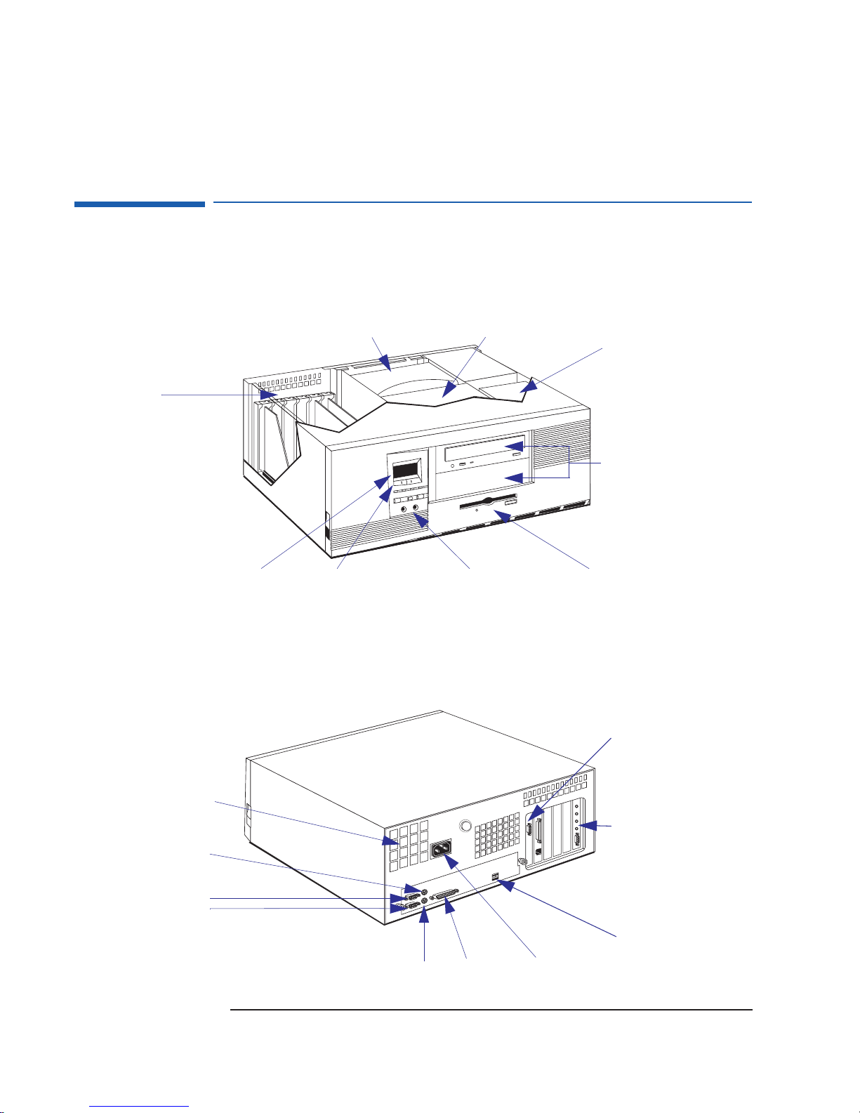
Desktop
Front view
Up to six accessory boards can
be installed:
• One AGP Slot
• Three 32-bit PCI Slots.
• One combination slot for either
a PCI or ISA accessory board.
• One ISA Slot. This contains the
audio board.
LCD Status panel
Rear View
Airflow Guide
System Board Switch label is
located above the CD-ROM cage.
Audio Front PanelHP MaxiLife LCD buttons
One 3.5-inch wide shelf
(floppy disk drive)
2 internal mass storage
shelves: 3.5-inch wide.
Upper shelf: 1-inch high
Lower shelf: 1.6-inch high
Two 5.25-inch wide by
1.6-inch high front-access
shelves (including CD ROM drive).
Note: The CD-ROM rails are
mounted directly onto the chassis
Power supply fan
Keyboard connector
Serial port A
Serial port B
8
Mouse connector
Parallel port
Display connector
Audio Board
Two USB connectors
Power connector
Page 9
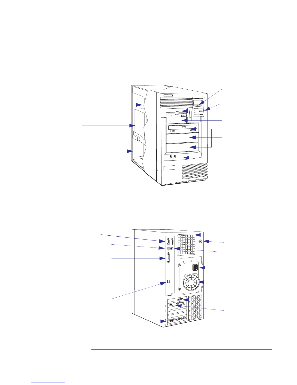
Minitower
HP Kayak PC Workstation Package
Rear View
Front view
2 internal mass storage
shelves: 3.5-inch wide.
Upper shelf: 1-inch high
Lower shelf: 1.6-inch high
Power Supply
Up to six accessory boards can be
installed:
• One AGP Slot
• Three 32-bit PCI Slots. On some
models, one of these slots is used
by the SCSI/LAN board.
• One combination slot for either a
PCI or ISA accessory board
• One ISA Slot. This contains the
audio board.
Serial ports A and B
Mouse connector
HP MaxiLife LCD buttons
LCD Status panel
Two 3.5-inch wide shelves
(including the floppy disk drive)
Three 5.25-inch wide x
1.6-inch high front-access
shelves (including CD ROM
drive)
Audio Front Panel
Processor fan
Key lock
Parallel port
2 USB connectors
Audio Board
Keyboard connector
Power connector
Power supply fan
Display connector
SCSI/LAN Board (on some
models only). Refer to the HP
Kayak Service Handbook for
Models and Accessories list.
9
Page 10
System Board Layout
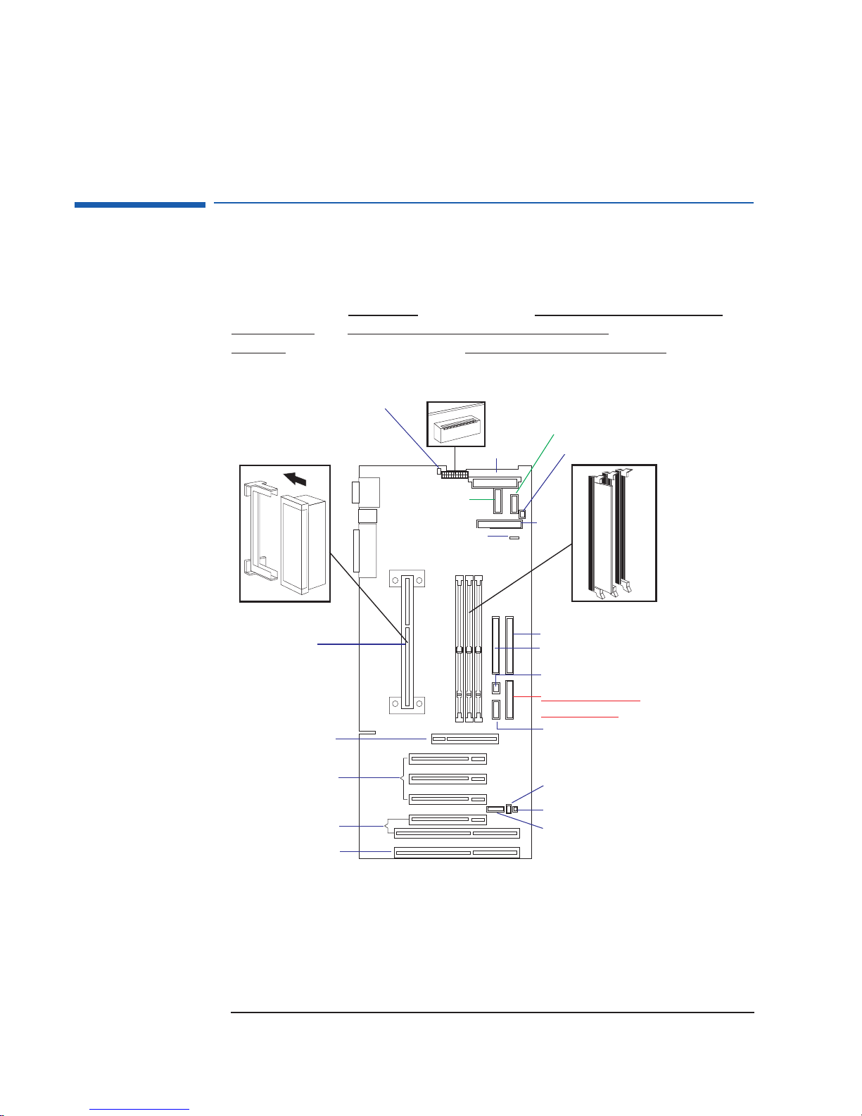
System Board Layout
The connector layout on the system board is the same for HP Kayak XA
Series 0503 and 0541 desktop and minitower models.
However, on the minitower
models, there is one connector for the LCD
status panel and one for the MaxiLife LCD status panel, while on the
desktop
models these options are combined into one connector.
Processor Fan
LCD Status Panel
External Battery
Single Slot 1
Processor
AGP Slot
Switches
Power
Minitower MaxiLife
Status Panel
Fan Disk Drive
Floppy
Disk
Drive
Memory Modules
IDE 2 Connector
IDE 1 Connector
Buzzer
Desktop MaxiLife and
LCD Status Panel
Audio
PCI/ISA Combination Slots
Note: There are two internal fans for the Desktop model. One fan for the Processor, and the other
for the PCI (I/O Fan). Whereas for the Minitower model, there are three internal fans. One fan for
the hard disk drive, one for the PCI (I/O Fan), and the other for the processor.
10
PCI Slots
ISA Slot
Wake On LAN
I/O Fan
HP External Start
Page 11

System Board Switches
System Board Switches
The first system board switch is reserved and should always be set to its
default setting. Switch 1 enables the PC Workstation to be fully compliant in
terms of electromagnetic emissions (clock dithering spread spectrum mode:
the processor clock frequency is moving slightly around its normal
frequency, less than 0.5%).
This implies that the electromegnetic emission pike at frequency processor
is less important. One potential drawback is that around (normally less than
1%) of performance can be lost. This switch is not documented in any of the
user guides and should never change from the default setting.
The next four switches (2 to 4) are used to set the ratio of processorfrequency to Processor-Local-bus-frequency. The last five switches (5 to 10)
are used to set the configuration for the PC Workstation.
NOTE On the desktop model, there is a System Board Switch label located above
the CD-ROM cage.
11
Page 12

Removing and Replacing the Cover
Removing and Replacing the Cover
WARNING: For your safety, never remove the PC’s cover without first removing the
power cord from the power outlet, and any connection to a
telecommunications network. Always replace the cover before switching on
the PC again.
On Desktop Models
Removing the Cover
Switch off the display and computer. Disconnect
all power cords, LAN or telecommunications cable and
accessory cables. If necessary, unlock the cover. The
lock and key for the cover are at the back of the PC
Workstation, just below the rear panel connectors.
Lift the two latches on the front sides of the
computer upwards.
Grasp the cover on the sides at the back of the
computer and slide it forwards and off the computer.
Replacing the Cover
Lower the cover completely onto the computer,
aligning the back cover with the inner back edge of the
PC Workstation’s case making sure that the two guides
at the bottom of the case slide into the two rails at the
base of the computer.
Firmly slide the cover backward into place. Ensure
that the restraining latches click into position.
If required, lock the cover using the key. If required,
lock the cover using the key. Reconnect all power cords,
LAN or telecommunications cable and accessory cables.
12
Ensure that the
restraining latches
click into position.
Page 13

On Minitower Models
Removing and Replacing the Cover
Removing the
Cover
Switch off the display and computer. Disconnect all
power cords, LAN or telecommunications cable and
accessory cables. If necessary, unlock the cover. The
lock and key for the cover are at the back of the PC
Workstation, just below the rear panel connectors.
Lift the two latches on the front sides
of the computer upwards.
Replacing the Cover
Ensure that the two latches on the
front sides of the cover are lifted up, and
that the lock is unlocked.
Slide the cover onto the computer, making
sure that the two guides at the bottom of the
case slide into the two rails at the base of the
computer. Firmly slide the cover backwards into
position.
Grasp the cover on the sides at the
back of the computer and slide it
forwards and off the computer.
Lower the two latches on the front
sides of the cover.
If required, lock the cover using the key. Reconnect all power
cords, LAN or telecommunications cable and accessory cables.
13
Page 14

Removing and Replacing the Power Supply Unit
Removing and Replacing the Power Supply Unit
On Desktop Models
Removing the Power Supply Unit
Refer to page 12 for instructions on how to remove and replace the cover. Disconnect the computer’s power cord and LAN cable
(if required).
Push up on the
underside of the power
supply at the end
closest to the internal
HDD cage.
Move the power
supply forward until the
rear edge is clear of the
chassis retaining back
bezel.
Replacing the Power Supply Unit
Reconnect the power supply cables to the
HDDs, FDD, CD-ROM and system board.
Rotate the power supply back into its recess.
Gently pull the cables downwards from underneath
the power supply to free the space.
Rotate the power supply out of its recess so that it sits upside-down on
top of the internal HDD cage. Disconnect the power supply cables to the
HDDs, FDD, CD-ROM and system board.
Power supply edge
is clear of the chassis
retaining back bezel.
➎
➍
The end of the power supply unit that is
closest to the internal HDD cage has to be entered
first.
➍ Then slide the power supply unit towards the
back of the recess until it fits under the retaining
edge of the rear chassis bezel.
➎ Push the power supply down into place.
14
➎
Page 15

Removing and Replacing the Power Supply Unit
On Minitower Models
Removing the Power Supply Unit
Refer to page 13 for instructions on how to remove and replace the cover. Disconnect the computer’s power cord
and LAN cable (if required).
(a) Disconnect the fan from the connector near the
right-hand edge of the system board;
(a)
(b) Press the retaining buttons on each side of the
airflow guide and lift out of the chassis.
Unscrew the four self-retaining screws at the back of the
power supply.
(b)
Slide the power supply unit until it stops. Disconnect the power
supply cables, then continue to slide the power supply unit out of the
computer.
15
Page 16

Power Supply Unit
Replacing the Power Supply Unit
Check that all internal cables are safely routed.
Slide the power supply unit back into the
computer until it stops. Reconnect the power
supply cables, then continue to slide the power
supply unit into the computer.
Tighten the four self-retaining screws.
➍ (a) Replace the airflow guide;
(b) Reconnect the fan connector to the system
board.
Power Supply Unit
HP Kayak XA Series 0503 and 0541 Desktop and Minitower PC
Workstations include a 200 W power supply unit with a manual voltage
switch selector. This power supply unit does not support accessory boards
that require a large amount of power.
It should be noted, that the first shipments of HP Kayak XA Series 05xx PC
Workstations included a 260 W automatic voltage selector. However, all
subsequent models are shipped with a 200 W power supply unit.
All documentation and related data sheets to the HP Kayak XA Series 0503
and 0541 PC Workstations, only make reference to 200 W power supply
units.
16
Page 17

HP MaxiLife Utility
HP MaxiLife Utility
HP MaxiLife is a hardware monitoring chip which is resident on the system
board. This chip receives data about the various system components via a
dedicated I
error state (for example, there is a CPU failure), it displays a warning with a
flashing LED and message on its LCD that specifies which component has
the problem.
Due to HP MaxiLife’s system independent design, even if there is a serious
component failure, it remains in operation and is able to indicate what the
problem is via the LCD.
For the HP MaxiLife to work correctly, the PC Workstation must always be
connected to a grounded outlet. This enables the PC Workstation’s hardware
monitoring chip to be active, even if the system has been powered off.
2
C bus. If it detects a potential error or that a component is in an
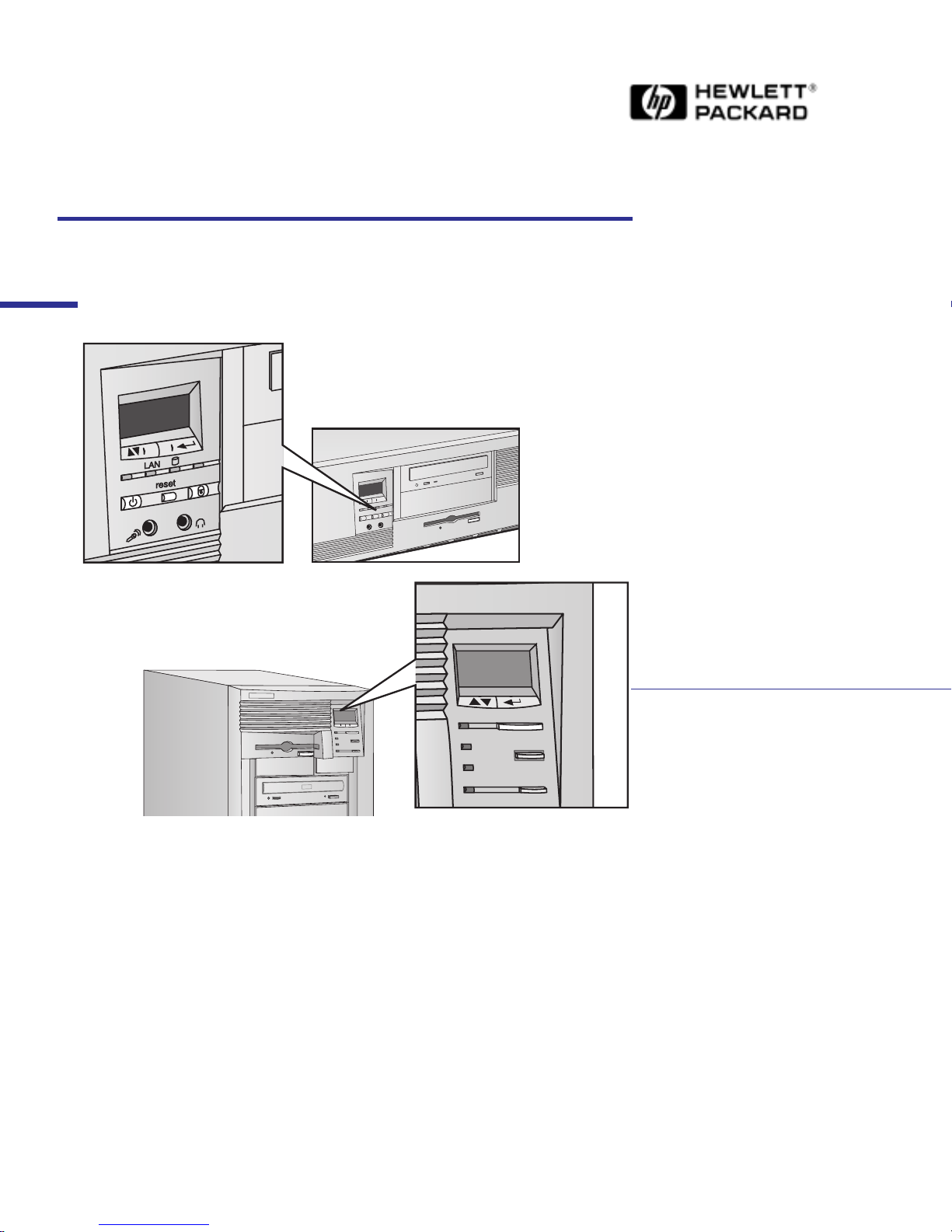
The following diagram shows where the LCD is located on the HP Kayak
XA Series 0503 and 0541 desktop and minitower PC Workstations.
Use this button to
validate a menu
item
Use this button to scroll
through the menu items
Use this button to scroll
through the menu items
Use this button to
validate a menu
item
17
Page 18

HP MaxiLife Utility
The following menus are available on the HP MaxiLife utility when pressing
the menu button:
• System Info. Obtains information from the BIOS and the system’s Serial
EEPROM from a previously successful boot. This information includes:
product name (HP Kayak XA) BIOS version, serial number, the number of
processors and speed, size of memory for each DIMM socket.
• Boot Steps. Shows the Power-On Self Test (POST) codes during the
system startup. The POST code is provided by the BIOS and is displayed
on the LCD panel as soon as it is available. If the system stops during the
startup, the last successful boot step POST code is displayed on the LCD.
• Diagnostics. Runs a set of diagnostics assessing the system’s
components. Results of the tests OK/FAIL are displayed on the LCD one
after another when the user presses the button.
Error Messages
When the PC is turned on (pressing the ON/OFF button), the system
initiates the normal startup sequence. A first diagnostic (called pre-boot
diagnostics) is run to check the presence of the processor, DIMM and power
supply.
MaxiLife does not purposely ‘freeze’ the system if an error is detected.
However, some critical hardware errors are fatal to the system and will
prevent the system from starting (for example, ‘Power’, ‘Board PLL’ are
serious malfunctions that will prevent the CPU from working correctly).
Errors that are not so critical (for example, ‘CPU Socket’ for missing
processor and ‘NO RAM’) are also detected by the POST and will abort the
boot process after beeping. The ‘RAM type’ error, however, is only detected
by POST, with the same abort process.
Finally, while the PC is working, fan and temperature checks are conducted
continuously and any anomaly reported (for example, a fan error when a
cable is not connected). This type of error disappears dynamically when the
problem has been fixed (for example, the fan cable has been reconnected).
18
Page 19

If an error is detected, a screen appears on the LCD panel. The following
table shows the test sequence carried out, the type of error message, and
the action to take.The errors mentioned correspond to standard error codes
(they are displayed without you having to press a key on the LCD status
panel).
Test Error Code Action to Take
HP MaxiLife Utility
1 When pressing one of the LCD status
panel buttons, nothing is displayed.
2 When the system is powered on, nothing is
displayed.
Presence of CPU processor slot. CPU SOCKET • Check that the CPU is correctly installed in the processor
Monitoring of some voltages: 12V POWER SUPPLY • Check the power supply connectors, CPU.
Number of installed DIMMs NO RAM • Check that the memory module is correctly installed in the
Compatibility of DIMMs. The BIOS checks that
the inserted DIMMs are both compatible with
one another, and compatible with the Front Side
Bus frequency.
System board clock generators (PLL). BOARD PLL • Check the power supply connector.
Monitoring of power signals to the CPU. This
checks the entire power system from the power
supply outlet to the CPU.
LCD status panel is
blank
RAM TYPE • Check the installed memory modules. This error occurs when
POWER • Check that the processor is correctly installed.
• Check that the two cables to the LCD status panel are properly
connected (refer to the system board layout for position).
• Check that the PC’s power cable is plugged in.
socket.
The error message could also show: Power CPU.
memory socket.
mixing incompatible memory modules, for example, when
installing a 66 MHz DIMM on a 350 MHz or higher system, or
when mixing Unbuffered and Registered memory modules.
• Replace the system board (PLL clock generator).
• Check the power supply unit connectors.
Availability of video board. It is also checked by
the BIOS. If an error is detected, it is not a fatal
one and the BIOS will continue its execution
normally.
Check on ability of CPU to run a given code. HP
MaxiLife waits for a synchronization event from
the BIOS. Any failure that prevents the
execution of the firmware will trigger an error.
The BIOS then executes the Power On Self Test
(POST) sequence. In this phase, HP MaxiLife
waits for any error messages that the BIOS may
issue.
NO VIDEO • Check that the video board is correctly installed.
Note: No error is detected if a monitor is not connected to an
installed video board.
BIOS • Flash the latest version of the system BIOS by using the system
recovery procedure. Set switch 10 to the down position.
• Check that the RAM is correctly installed.
• Check that the CPU is firmly inserted.
POST XXXX • If the screen is working, you can obtain the meaning of the
error by typing “Enter” at the end of the POST. Or, you can
check the list of errors that are available on the HP World-Wide
Web support page.
19
Page 20

HP MaxiLife Utility
Test Error Code Action to Take
During normal usage of the PC, HP MaxiLife
continuously checks vital parameters of the
system. If an error occurs, a message is
automatically displayed on the LCD panel.
1.
Special cases: Board PLL = System board needs replacing. CPU error = Reset or power off the system to recover.
FAN CPU • Check the connection of the corresponding component, which
could be: “Temp IO slot”, “Power errors, “Fan CPU”, “Board
PLL”, “Temp disk”, “Temp CPU”, “Fan disk”, “Fan IO slot”, “CPU
1
error”.
Special Cases 1 If a CPU is not installed correctly.
The “Power CPUx” or “CPU socket” or “BIOS” message may appear.
This will depend on which end of the CPU connector is not
correctly inserted.
2 Only one pre-boot error reported on the system.
Hidden errors will be revealed when the current error has been fixed.
3 If a “No Video Error” message is displayed, even though the video is
working correctly.
With some specific add-on boards, this error may appear even when
the system is working correctly. To check if this is the case, remove all
add-on boards from the basic system configuration.
20
Page 21

Running the MaxiLife Diagnostics Program
Running the MaxiLife Diagnostics Program
Can I run the HP MaxiLife Utility Diagnostics program when the
computer is powered off?
Yes, you can. However, the power cable must be connected to a
wall socket. The Diagnostics program will run low-level tests
on the memory, processor, power supply, video board and the
main clock generator on the system board (Board PLL).
Even with the computer powered off (the LCD status panel will be blank),
HP MaxiLife still runs and monitors the state of the LCD buttons. If one of
the two buttons is pressed, the LCD status panel will display a second menu.
To run the diagnostics option, proceed as follows:
1 Press one of the LCD buttons, or , to display the main screen.
2 Use the button to scroll through the menus until you reach the
Diags
option. Then press the button.
3 Use the button to select
Power on. The main power supply is
started, enabling the hardware monitoring chip to assess the status of the
computer’s components.
NOTE Although the main power supply has been started, the computer does not
complete a normal boot.
4 Use the button to scroll through the
Diags option. The system
components are tested in sequence with the results displayed on the
status panel. Press the Next button to move on to the following test.
If no errors are detected, you can exit the test session by pressing
the button. The main power supply will be turned off and the
LCD status screen will become blank.
If an error is detected, a short message will be displayed indicating
which component has a problem.
For example: DIMM found:0
This indicates that there are no memory modules detected.
NOTE The display of a warning with a flashing LED and message on the LCD status
panel is not available when the computer has been powered off.
21
Page 22

Checking the System Configuration
Checking the System Configuration
I need to check the system configuration and, in particular, the
BIOS version. Can this be checked from the LCD status panel?
Yes, it can. System configuration (including BIOS version)
can be checked through the System Info menu.
The System Info menu also provides about the following information:
• Product name (HP Kayak XA).
• Number and speed of the processor.
• Number and size of DIMMs.
• Serial Number.
All information provided by the BIOS has been stored (during a normal
boot) into the serial EEPROM. This information is updated every time the
system is successfully rebooted.
To check the system configuration, proceed as follows:
1 Press one of the LCD buttons, or , to display the main screen. The
following menu is displayed.
System info
Boot steps
Next Go
2 To view the components in the System Info menu, use the button to
scroll through the information screens.
3 After the last item has been displayed, the LCD returns to the Main
screen.
22
Page 23

Checking the Display Screen
Checking the Display Screen
I have turned on the PC Workstation, but nothing appears on the
screen. How can I find out what the problem is?
Check the LCD status panel screen for an error message (a
table on page 19
and the action to take to solve the problems).
When the PC is turned on, the HP MaxiLife diagnostics utility will first check
the system components before it initiates the system startup sequence. If it
detects an error at this stage of the pre-boot checks, an error screen will be
displayed on the LCD status panel. If no errors are found, another screen
with a “smiling icon” will be displayed.
lists all the different types of error messages
Error!
Board PLL
An example of an error screen that could appear on
the LCD status panel.
Following the pre-boot checks, the POST sequence is then initiated. If an
error is detected, a POST Error code is displayed. Refer to the POST error
codes table contained in the Service Handbook for further explanation.
Error!
POST XXXX
An example of a POST error code screen that could
appear on the LCD status panel.
HP KAYAK XA
This screen indicates that the pre-boot checks have
not found any errors.
HP KAYAK XA
This screen indicates that no errors have been
found.
23
Page 24

Checking the Display Screen
You can also use the Boot Steps option from the LCD status panel. It
shows the POST steps during the system startup. If the system stops during
the startup, the last successful boot step POST code is displayed on the LCD
status panel. For support purposes, POST steps are only shown as POST
codes. To access
Boot Steps, proceed as follows:
1 Press one of the LCD buttons, or , to display the main screen.
2 Use the button to scroll through the menus until you reach the
steps
option. Then press the button.
Boot
For further details on the HP MaxiLife diagnostics utility, refer to the User’s
Guide. This provides examples of error screens arising from pre-boot checks
and explains how to configure the HP LCD control buttons.
You can also obtain details of POST codes and POST error codes from the
HP World Wide Web site: http//www.hp.com/go/kayaksupport.
Select the required platform and documentation, and then choose the
document dealing with MaxiLife or LCD errors.
24
Page 25

Upgrading Main Memory Modules
Upgrading Main Memory Modules
The PC Workstation has 64 MB of Non-ECC SDRAM main memory
installed in one DIMM slot. Can a 256 MB Registered ECC SDRAM
memory module be added to a second DIMM slot to upgrade the
memory?
No, it cannot. Registered memory modules are not supported.
To upgrade the memory, you can only use either, 100 MHz
ECC or Non-ECC SDRAM unbuffered
HP Kayak XA Series 0503 and 0541 PC Workstations are equipped with a
100 MHz Front Side Bus (FSB), and therefore uses only 100 MHz
unbuffered ECC or Non-ECC SDRAM memory modules. Memory modules
running at 66 MHz are not supported by the 100 MHz FSB.
memory modules.
The main memory controller supports three DIMM sockets: Mem 1, Mem 2
and Mem 3. Each socket can host a 168-pin SDRAM memory module,
running at 100 MHz, supporting unbuffered memory modules only. These
are available in 32 MB, 64 MB, 128 MB and 256 MB unbuffered ECC SDRAM
and non-ECC memory modules. A maximum of 768 MB using multiples
(3 x 256MB) unbuffered memory may be installed.
25
Page 26

Identifying Video Boards on an HP Kayak XA
Identifying Video Boards on an HP Kayak XA
How do I identify whether an HP Kayak XA PC Workstation has a
Matrox Millennium G200 AGP video board or an ELSA GLoria
Synergy+ AGP video board.
Check the support label on the back of the PC. The Matrox
Millennium G200 Kayak XA model is labeled
XA6/XXXserie0503, while the ELSA GLoria Synergy+ is
labeled XA6/XXXserie0541.
The Matrox Millennium G200 video board has a total of 8 MB of installed
SGRAM video memory, which can be upgraded to 16 MB by adding a
SO_DIMM (SGRAM) memory module accessory. It also supports full AGP
mode (double clocking, 2 x 66 MHz and sideband addressing).
Flash EEPROM
Display connector
The ELSA GLoria Synergy+ has 4 MB of installed SGRAM video memory.
Added to this, there is a preinstalled 4 MB SO_DIMM (SGRAM) memory
module, giving a total of 8 MB, which cannot be upgraded. The ELSA GLoria
Synergy+ supports the basic AGP mode (1 x 66 MHz).
Matrox Millennium MGA 200 Video Board
MGA 200 Graphics processor
1 MB SGRAM
memory chips
installed on the
video board
AGP connector
8 MB (2 x 4 MB) SO_DIMM SGRAM memory
module added to give a total of 16 MB.
2 x 4 MB of preinstalled memory chips on
the video board.
ELSA GLoria Synergy+ Video Board
4 MB SO_DIMM (SGRAM)
preinstalled memory module
1 MB SGRAM
memory chips
installed on the
video board
AGP connector
26
Display connector
Permedia 2A Graphics processor: Improves
support for multi-screen environments and is
PC98 certified.
Page 27

Connecting Devices on the SCSI/LAN Combination Board
Connecting Devices on the SCSI/LAN Combination Board
The SCSI/LAN Combination Board includes two SCSI connectors:
an Internal Wide and an Internal Narrow. Can I connect devices to
both these connectors at the same time?
No, you cannot. Connecting devices to both these devices at
the same time will result in a badly “terminated” SCSI bus.
For HP Kayak XA Series 0503 and 0541 PC Workstations supplied with a
SCSI / 10BT/100TX LAN combination board, only an Internal Narrow SCSI
cable is provided.
The following diagram shows the SCSI/LAN Combo board connectors.
Thirteen-pin connector (J4)
to connect the ExtStart
cable to the system board.
LAN Controller
Optional Boot Rom
Socket (option)
External Wide SCSI
connector (J7).
LED which indicates LAN link
RJ-45 connector.
Three-pin connector (J8)
to connect the WOL cable
to the system board.
PCI connector.
Internal Wide SCSI
connector (J3 - not used).
Internal Narrow SCSI
connector (J9 - used).
Flash memory (128 KB)
Symbios Logic
(53C875JE)
PCI-to-PCI Bridge
27
Page 28

Flashing the Latest Version of the System BIOS
Flashing the Latest Version of the System BIOS
How can I make sure that the MaxiLife firmware has been
correctly upgraded during flash BIOS?
Ensure that you use the option /c to update the MaxiLife
firmware of the LCD for a clean configuration (except the
date and time). If this option is not used, the MaxiLife
firmware will not be updated.
BIOS upgrades can be downloaded from the HP World Wide Web site (see
below to access the World-Wide Web URL). To download a BIOS upgrade,
connect to the HP Web site and follow the on-screen instructions to
download the flash utility programs (
PHLASH.EXE), the BIOS file (HU1xxxyy.FUL), and a file called
platform.bin, onto a bootable diskette.
FLASH.BAT, AUTOEXEC.BAT and
Access HP World Wide
Web Site
When you’ve downloaded the files, insert the diskette in drive A and re-boot
the computer. Enter the command in the following format:
PHLASH /c HU1xxxyy.FUL
to update the MaxiLife firmware.
/c
xxx replaced by the version that you have downloaded.
yy language that you have downloaded.
World-Wide Web URL
http://www.hp.com/go/kayaksupport
28
Page 29

Complete the Questionnaire to Check Your Understanding
Complete the Questionnaire
to Check Your Understanding
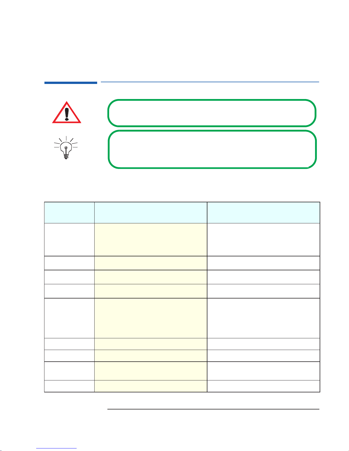
Circle each letter that corresponds to a correct answer. (There may be more
than one correct answer to each question).
1 Do HP Kayak XA Series 0503 and 0541 PC Workstations support
Klamath processors?
a Yes, they do. Both Klamath and Deschutes Slot 1 processors are
supported.
b No, they don’t. Only Deschutes Slot 1 processors are supported.
2 What is the consumption power supply of the HP Kayak XA Series
0503 and 0541 PC Workstations. And, does it have any affect on
accessory boards?
a HP Kayak XA Series 0503 and 0541 PC Workstations are supplied
with a 200 W power supply unit. This power supply unit is not capable
of supporting any high power consuming accessory boards.
b HP Kayak XA Series 0503 and 0541 PC Workstations are supplied
with a 260 W power supply unit. This power supply unit is capable of
supporting high power consuming accessory boards.
3 On recently shipped HP Kayak XA Series 0503 and 0541 PC
Workstations, is the voltage switch selector, manual or automatic?
a The most recently shipped HP Kayak XA Series 05xx PC Workstations
include a 200 W power supply unit with a manual voltage switch
selector.
b The most recently shipped HP Kayak XA Series 05xx PC Workstations
include a 200 W power supply unit with an automatic voltage switch
selector
4 Can a maximum of 768 MB of unbuffered ECC SDRAM memory
modules be installed on HP Kayak XA Series 0503 and 0541 PC
Workstations?
a Yes, by installing 3 x 256 MB of unbuffered memory modules.
b No. On HP Kayak XA Series 0503 and 0541 PC Workstations, the
maximum size of an unbuffered memory module is 128 MB
(3 x 128 MB = 384 MB).
29
Page 30

Complete the Questionnaire to Check Your Understanding
5 Can I install unbuffered ECC SDRAM memory modules running at
66 MHz on a 100 MHz Front Side Bus?
a Yes, you can. The 100 MHz FSB supports unbuffered ECC SDRAM
memory modules running at 66 MHz and 100 MHz.
b No, you cannot. Unbuffered ECC SDRAM memory modules running at
66 MHz are not supported on a 100 MHz FSB.
6 How do I identify whether an HP Kayak XA Series 0503 and 0541 PC
Workstation has a Matrox Millennium G200 video board or an Elsa
GLoria Synergy+?
a Check the support label located at the back of the box on the right-
hand-side.
b Check the part number on the back of the box.
c Check the rear panel on the video board.
7 On the HP Kayak XA Series 0503 and 0541 PC Workstations, a single
processor system has been upgraded to a dual processor system. Is it
necessary to install a VRM?
a Yes, it is. Each processor must be accompanied with a VRM.
b No, it isn’t. On the HP Kayak XA Series 0503 and 0541 PC
Workstations, the Pentium II Deschutes Slot 1 processors include an
integrated heatsink, and level-1 and level-2 cache memory. Therefore,
VRMs are not required.
c The HP Kayak XA Series 0503 and 0541 have only one processor slot,
and the VRM is built into the system board. Therefore, it is not possible
to upgrade to a dual processor system nor install a VRM.
8 To run the MaxiLife diagnostics program, does the computer need to
be powered on?
a No, it doesn’t. As long as a power cable is connected, HP MaxiLife can
be started, and the diagnostics program run to check the various
system components.
b Yes, it does. This can be easily checked, because the LCD status panel
will be blank.
c No, it doesn’t. Even with the power cable disconnected, MaxiLife runs
continuously and monitors the state of the various system
components.
30
Page 31

Complete the Questionnaire to Check Your Understanding
9 Can I upgrade a Matrox Millennium G200 video board using SGRAM
memory modules?
a Yes, you can. There is a total of 8 MB of installed SGRAM video memory
on the video board, which can be upgraded to 16 MB by adding a 8 MB
(2 x 4 MB) SO_DIMM SGRAM memory module accessory (this is not
an HP accessory).
b No, you cannot. There is a total of 8 MB of installed SGRAM video
memory on the video board, which cannot be upgraded.
c No, you cannot. The Matrox Millennium G200 uses SDRAM memory
modules only.
10 Before installing or replacing a component, do I need to use a wrist
strap and ESD mat?
a Yes, you do. Electrostatic Discharge (ESD) can damage processors,
memory, hard disk drives, accessory boards and other components.
b No, you do not have to. The ESD package is non-conductive.
31
Page 32

Answers and Explanations
Answers and Explanations
1 Do HP Kayak XA Series 0503 and 0541 PC Workstations support
Klamath processors?
b No, they don’t. Only Deschutes Slot 1 processors are supported.
2 What is the power supply consumption of the HP Kayak XA Series
0503 and 0541 PC Workstations. And, does it have any affect on
accessory boards
a HP Kayak XA Series 0503 and 0541 PC Workstations are supplied
with a 200 W power supply unit. This power supply unit is not
capable of supporting any high power consuming accessory boards.
3 On recently shipped HP Kayak XA Series 0503 and 0541 PC
Workstations, is the voltage switch selector, manual or automatic?
a The most recently shipped HP Kayak XA Series 05xx PC
Workstations include a 200 W power supply unit with a manual
voltage switch selector.
4 Can a maximum of 768 MB of unbuffered ECC SDRAM memory
modules be installed on HP Kayak XA Series 0503 and 0541 PC
Workstations?
a Yes, by installing 3 x 256 MB of unbuffered memory modules.
5 Can I install unbuffered ECC SDRAM memory modules running at
66 MHz on a 100 MHz Front Side Bus?
b No, you cannot. Unbuffered ECC SDRAM memory modules running
at 66 MHz are not supported on a 100 MHz FSB.
6 How do I identify whether an HP Kayak XA Series 0503 and 0541 PC
Workstation has a Matrox Millennium G200 video board or an Elsa
GLoria Synergy+?
a Check the support label located at the back of the box on the right-
hand-side.
The ELSA GLoria Synergy Kayak XA model is labeled:
XA6/XXXserie0541.
The Matrox Millennium G200 Kayak XA model is labeled:
XA6/XXXserie0503.
32
Page 33

Answers and Explanations
7 On the HP Kayak XA Series 0503 and 0541 PC Workstation, a single
processor system has been upgraded to a dual processor system. Is it
necessary to install a VRM?
c The HP Kayak XA Series 0503 and 0541 have only one processor slot,
and the VRM is built into the system board. Therefore, it is not
possible to upgrade to a dual processor system nor install a VRM.
8 To run the MaxiLife diagnostics program, does the computer need to
be powered on?
a No, it doesn’t. As long as a power cable is connected, HP MaxiLife can
be started, and the diagnostics program run to check the various
system components.
9 Can I upgrade a Matrox Millennium G200 video board using SGRAM
memory modules?
a Yes, you can. There is a total of 8 MB of installed SGRAM video
memory on the video board, which can be upgraded to 16 MB by
adding a 8 MB (2 x 4 MB) SO_DIMM SGRAM memory module
accessory (this is not an HP accessory).
10 Before installing or replacing a component, do I need to use a wrist
strap and ESD mat?
a Yes, you do. Electrostatic Discharge (ESD) can damage processors,
memory, hard disk drives, accessory boards and other components.
The ESD package is conductive and is easy to recognize from its label. Do
not take the new component out of its ESD package before connecting
your wrist strap and ESD mat to a suitable earthed point. Also, do not
forget to use the ESD package provided with the new part to return the
old one.
33
Page 34

Answers and Explanations
34
Page 35

Electrostatic Discharge Warning
Electrostatic Discharge (ESD) can damage processors, memory,
hard disk drives, accessory boards and other components.
The ESD package is conductive and is easy to recognize from its
label.
Before installing or replacing a component:
1 Do not take the new component out of its ESD package before
connecting your wrist strap and ESD mat to a suitably earthed
point.
2 Do not forget to use the ESD
package provided with the new part
to return the old one.
The ESD package is conductive and
is easy to recognize from its label.
Page 36

Manual Part Number: D6738-90901
 Loading...