

Page 1
Page 2

Page 3

User’s Guide
HP SureStore HD Server 4000
Page 4

© Copyright 1999
Hewlett-Packard Company.
All rights reserved. Reproduction, adaptation or
translation without prior written permission is
prohibited, except as allowed under the copyright
laws.
Publication number
5967-9979
User’s Guide, First Edition,
August 1999
Applicable Products:
J3290A, J3291A, J3292A
Safety Considerations
Prior to the installation and use of this product,
review all safety markings and instructions.
Instruction Manual Symbol.
!
WARNING
CAUTION
If the product is marked with
this symbol, refer to product
manuals to protect the product
from damage.
Denotes a hazard that can
cause injury.
Denotes a hazard that can
damage equipment or data.
Trademark Credits
Microsoft
U.S. registered trademarks of Microsoft
Corporation. Netscape and Netscape Navigator
are U.S. trademarks of Netscape
Communications Corporation.
Warranty
This Document. The information contained in
this document is subject to change without
notice.
HEWLETT-PACKARD COMPANY MAKES NO
WARRANTY OF ANY KIND WITH REGARD TO
THIS MATERIAL, INCLUDING, BUT NOT
LIMITED TO, THE IMPLIED WARRANTIES
OF MERCHANTABILITY AND FITNESS FOR
A PARTICULAR PURPOSE.
Hewlett-Packard shall not be liable for errors
contained herein or for incidental or
consequential damages in connection with the
furnishing, performance or use of this material.
The Product. Your product warranty and
warranty service information is in appendix B in
this guide.
Product Support
HP's Electronic Support Center:
http://www.hp.com/support/hdserver
See also appendix A, “Getting Support”.
®
, Windows®, and Windows NT® are
Hewlett-Packard Company
8000 Foothills Boulevard
Roseville, California
95747-6588
Do not proceed beyond a
notice until you have understood the hazard and
have taken appropriate precautions.
Grounding. This product provides a protective
earthing terminal. There must be an
uninterruptible safety earth ground from the
main power source to the product’s input wiring
terminals, power cords, or supplied power cord
set. Whenever it is likely that the protection has
been impaired, disconnect the power cords until
the ground has been restored.
If your LAN covers an area served by more than
one power distribution system, be sure their
safety grounds are securely interconnected.
LAN cables may occasionally be subject to
hazardous transient voltages (such as lightning
or disturbances in the electrical utilities power
grid). Handle exposed metal components of the
network with caution.
For more safety information, see the
“Safety Statements” section starting on page D-4.
Servicing. There are no user-serviceable parts
inside the user-replaceable modules comprising
the product. Any servicing, adjustment,
maintenance, or repair must be performed only
by service-trained personnel.
Register Now!
Register your HP NAS product now and receive:
Technical support updates
•
Special Hewlett-Packard offers
•
Details on new products and technologies
•
http://www.hp.com/go/surestore_nas
WARNING
or
CAUTION
Page 5

About This Guide
This
User’s Guide
HD Server 4000. How to use the chapters is described below.
You can read about network attached storage and the features of
this file server in chapter 1.
1. Product Overview
The first time you install the server, you can use the large sheet
titled
Using that sheet as your primary aid, you can follow its steps and
follow its references to this
additions and for customizing the configuration once the server is
started up.
Or you can use chapter 2 of this manual for installing the server.
Quick Setup
2. Installation
setup, including basic configuration, and to setting up and
maintaining the hardware. It contains references to other
chapters for options. For example, after completing chapter 2,
you may need to further customize your configuration using
chapter 4 (see below).
aids in installation and use of the HP SureStore
is an introduction to the product.
to aid in the initial installation of your server.
User’s Guide
is a detailed guide to initial installation and
for optional hardware
Once the server has been started up and you wish to change or
check the configuration, use chapters 3 and 4.
3. Configuration Using the Control Panel
configuration and operational tasks done at the control panel in
front of the server.
4. Configuration Using a Browser: HD Server Admin
describes the configuration and management tasks that use
the embedded web tool HD Server Admin at any station on the
network.
After completing all the installation and configuration steps, the
server is ready to serve users on the network, just like any other file
server. For instructions to map a drive to the server for a client
station, use chapter 5.
5. Setting Up Client Access
can find and connect to the server.
describes how a network client
describes the
3
Page 6

When the server has been fully installed and you need instructions
on various methods to restart it, use chapter 6.
6. Shutting down and Restarting
describes the procedures
for shutting down the server, restarting it, and power cycling,
along with the needs for those procedures. The operating states
of the server are described.
The previous chapters aid in setting up the server. The remaining
chapters aid in tasks that you may or may not need to perform.
When you need to add a hard disk module or an optional tape drive,
use chapter 7 or 8.
7. Adding Hard Disk Drives
describes the selection,
installation, and setup of additional disk drive modules.
8. Adding a Tape Drive
describes selection and installation of
an optional tape drive. You can add an internal tape drive or
attach an external tape drive.
Once a tape drive is installed or attached to the server, use
chapter 9 to aid in ongoing backup and restore tasks.
9. Backing Up and Restoring Files
describes the tasks of
backing up your server and of restoring files to the server.
To update the firmware running on your server, use chapter 10.
10. Updating the Firmware
describes checking the current
firmware version and checking for other versions available. It
describes downloading a new version and updating the server to
use new firmware.
If you encounter problems with your server, use chapter 11.
11. Resolving Problems with Your Server
describes the
indicators and symptoms you could encounter, describes how to
isolate causes, and describes how to resolve the problem or
repair the faulty component.
The appendices provide supplemental reference information—
technical and regulatory specifications, and support and warranty
services.
4
Page 7

Contents
1. Product Overview
What is Network Attached Storage? 1-1
HP SureStore HD Server 4000 1-1
Features 1-2
2. Installation
Installation Summary Checklist 2-2
Unpacking Components 2-3
Adding Modules 2-5
Rack Mounting 2-5
Preparation Checklist 2-6
Connecting and Starting Up 2-8
Startup Steps 2-8
Control Panel Setup 2-9
Verify Normal Operating State 2-12
Web Browser Network Setup 2-13
Maintain Hardware Operation 2-16
3. Configuration Using the Control Panel
Control Panel Reference 3-1
Accessing Control Panel Parameters 3-2
View Mode 3-2
Setup Mode 3-2
Supplying the Password for Access 3-3
Setup Parameters and Procedures 3-4
Setting Password, Auto-Restart, Link Speed 3-4
Exiting the Control Panel 3-5
Reference Table: Control Panel Parameters, Menus, and Settings 3-6
5
Page 8

4. Configuration Using a Browser: HD Server Admin
Using a Web Browser on the Network 4-1
Setup with HD Server Admin 4-3
Initial Page 4-3
Operating Features of HD Server Admin 4-4
Server Name 4-5
Date and Time 4-5
Automatic Server Restart 4-5
Administrator Username and Password 4-5
Network Configuration 4-6
Set Up Disks 4-7
Set Up Shares 4-10
Set Up Users and Groups 4-11
SNMP 4-12
Event Logging 4-12
E-Mail 4-12
Set Up Backup Schedule 4-13
Back Up Changes 4-13
Restart the Server to Effect Changes 4-13
Monitoring Status with HD Server Admin 4-14
Check Status 4-14
Check File System 4-14
Check Events 4-14
Check Backup Schedule and Log 4-14
5. Setting Up Client Access
6. Shutting Down and Restarting
Starting Up the Server 6-1
Normal Operating State 6-4
Shutting Down, Restarting, Cycling Power 6-5
Shutdown Procedures 6-5
Restart Procedures 6-6
Power Cycle Procedure 6-6
Reset to “First Time” Defaults Procedure 6-7
Summary of Operating States 6-10
6
Page 9

7. Adding Hard Disk Drives
Hard Disk Drive Modules Available 7-1
Install the Drive Module 7-2
Startup and Configuration 7-6
8. Adding a Tape Drive
Installing an Internal Tape Drive 8-2
Attaching an External Tape Drive 8-8
Using Network Backup with the HD Server 8-10
9. Backing Up and Restoring Files
Using an Installed or Attached Tape Drive 9-1
Capacity 9-2
Reliability 9-2
Maintaining Tape Drives 9-3
Specifying and Scheduling a Backup 9-4
Backup Now 9-6
Schedule Backups 9-7
Making a Disaster Recovery Backup Tape 9-7
Restoring Files 9-9
Start Restore 9-10
Recovering the File System 9-10
Tape Utilities 9-11
Select Tape Drive 9-11
Erase Tape 9-11
Create Tape Catalog 9-11
Test Tape 9-11
Unload/Eject Tape 9-11
Backup/Restore Log 9-11
10. Updating the Firmware
Checking Current Image 10-1
Checking for an Update 10-1
Downloading an Update 10-2
Updating the Server 10-2
Switching to the Backup Image 10-3
7
Page 10

11. Resolving Problems with Your Server
Check Indicators 11-1
Normal Indications 11-1
Abnormal Indications 11-3
Check Status in HD Server Admin 11-5
Problem Lookup 11-7
Lights (LEDs) Not Normal 11-7
Alerts on Control Panel 11-7
Other Unexpected Messages on Control Panel 11-8
Failure/Warning Status in HD Server Admin 11-9
Writing/Reading Data Fails 11-9
Server Not Appearing in Network Neighborhood 11-10
Administrator Web Access Fails 11-10
Network Failures 11-11
Access Denied when Map Drive Attempted 11-11
Access Security Fails 11-11
Drive Fails to Spin Up 11-12
Excessive Drive Temperature 11-12
Lost Administrator Password 11-12
Lost or Damaged Files 11-13
Disaster: Lost or Damaged File System 11-13
Lost or Failed Server Configuration 11-14
Firmware Fails
to Run 11-15
Backup Device Not Appearing in HD Server Admin 11-16
Resolution and Repair Procedures 11-17
Shutdown 11-17
Restart 11-18
Power Cycle 11-18
Reset Defaults 11-19
Download New Firmware 11-19
Disaster Recovery 11-19
Replace Disk Drive Module 11-23
Open the Enclosure 11-25
Close the Enclosure and Start Up 11-27
Replace the Tape Drive 11-28
Replace the Server Module 11-31
To Repair Enclosure Components 11-35
8
Page 11

A. Getting Support
HP Customer Care Centers Phone Numbers A-1
Electronic Support Services A-2
B. Warranty
Obtaining Warranty Service B-1
Your Hewlett-Packard Limited Warranty B-2
One Year On-Site Warranty B-2
For Specific Regions B-3
For Australia and New Zealand B-3
Póliza de Garantía (México) B-3
Certificado de Garantia (Argentina) B-5
C. Specifications
Physical Specifications C-1
Electrical and Environmental C-1
Power C-2
Environmental C-2
Electromagnetic C-2
Safety C-2
HP 9.1-GB SCSI-2 Disk Drive Module C-3
HP SureStore DAT40i DDS-4 Tape Drive C-3
9
Page 12

D. Regulatory and Safety Information
Regulatory Statements D-1
FCC Statements D-1
Australia D-2
Canada D-2
Japan: VCCI Class B D-2
Taiwan: Class A D-2
European Union D-3
Safety Statements D-4
Chinese Safety Statement D-4
Lifting Precautions D-5
Mounting Precautions D-5
Index
10
Page 13
Product Overview
What is Network Attached Storage?
Network-attached storage (NAS) is one of the latest innovations in
the computer information storage world. It provides a simpler, more
reliable, and more cost-effective way to add shared storage to your
network. NAS requires very little setup and is easy to maintain.
This is achieved by using a streamlined technology called a thin
server, which also allows the NAS devices to be completely
independent of the general-purpose file server.
1
HP J3290A
HP J3291A
HP J3292A
HP SureStore HD Server 4000
The HP SureStore HD Server 4000 family of products are NAS
devices that attach directly to your network and provide dedicated
personal and shared file storage for workgroups and departments.
The products contain SCSI hard disks in a preconfigured RAID 5
array network file-sharing compatibility, and an easy-to-use
embedded web administration interface. They also provide the
added convenience of local internal or external tape backup, along
with e-mail and SNMP notification of critical events.
Benefits
Fast and easy to set up
•
Easy to administer and manage
•
Data redundancy and security
•
No software to load
•
No disruption to existing server operation
•
Product Overview 1-1
Page 14

Possible Uses
Personal directories
•
Shared group directories
•
File-based databases
•
Departmental or workgroup file server
•
Remote site file server
•
Temporary storage
•
Features
Disks and File System
Three to six SCSI hard disk drive modules
•
Expandable RAID 5 file system, already generated
•
Hot spare capability
•
Networking
10Base-T (Ethernet) or 100Base-TX (Fast Ethernet)
•
TCP/IP
•
Windows Networking
SMB
•
WINS support
•
Supported clients: Microsoft® Windows®95, 98, and
•
®
Windows NT
NT domain pass-through authentication
•
Administration and Management
Embedded web administration interface and web-based
•
installation wizard
Control panel LCD for basic configuration, with password
•
protection
DHCP/BOOTP and manual configuration of network
•
parameters
E-mail (SMTP) and SNMP alert notification
•
4
1-2 Product Overview
Page 15

Backup
Optional internal and external tape drive
•
Scheduled backups
•
Backup of shared directories over the network
•
System
Redundant power supplies and power cords
•
Internal tape drive option
•
Pedestal or rack mount with optional rack-mount kit
•
Automatic server restart
•
Firmware stored in Flash memory with firmware upgrades over
•
the network
Lockable enclosure and disk drives
•
Other network management tools such as HP OpenView,
•
HP TopTools, and other managers, through SNMP
gets.
sets
and
Product Overview 1-3
Page 16

1-4 Product Overview
Page 17

Installation
2
The first time the HP SureStore HD Server 4000 is started, it
automatically prompts and waits for the IP address setting at the
control panel. Then when you access the embedded web interface
using a web browser, the server runs an installation wizard. This
chapter is a guide to the entire installation process. It details the
installation steps and directs you to additional chapters if needed
for your particular installation.
A
Quick Setup
included along with this
installation process, from making the connections to setting up the
server. To add disk drive or tape drive modules and do further
customization for your particular network environment, you can
follow references in the
this
User’s Guide
If this is not the first time the server has been started (that is, it has
been started before and is not being reset to defaults), then use
chapter 6, “Shutting Down and Restarting”, instead of this chapter.
guide for the first installation of this product is also
User’s Guide
Quick Setup
.
. It portrays the entire
guide to those optional tasks in
Installation 2-1
Page 18

Installation Summary Checklist
Unpack components. (page 2-3)
❏
Optional:
❏
Optional:
❏
Use preparation checklist. (page 2-6)
❏
Attach network cable and power cords. (page 2-8)
❏
Switch on power. (page 2-8)
❏
At control panel, check lights and display. (page 2-8)
❏
Set the IP address, using either DHCP, BOOTP, or manual
❏
Add any disk drive and tape drive modules. (page 2-5)
Rack mount. (page 2-5)
entry at the control panel. (page 2-9)
Optional:
❏
❏
❏
Set a password for the control panel. (page 2-11)
Set the server to automatically restart if possible when
Additional parameters available on the control panel:
critical errors are encountered. (page 2-11)
Exit control panel setup and verify initialization. (page 2-11)
❏
Optional:
❏
Use a web browser on a PC on the network to run the
embedded web installation wizard, to set up additional
features: (page 2-13)
Administrator password
❏
Server name
❏
Date and time
❏
DNS
❏
WINS
❏
Optional:
❏
Use a web browser on PC or station on the network to
run the embedded HD Server Admin, for additional
configuration of the following: (chapter 4)
User-level security, users and groups and permissions.
❏
Optionally pass through authentication to an NT domain
controller. (page 4-10, page 4-11)
Passwords for share-level security. (page 4-10)
❏
Additional shares. (page 4-10)
❏
Additional disk drives. (chapter 7)
❏
Backup schedule. (chapter 9)
❏
Other automated services. (page 4-12)
❏
Restart the server if your changes require it. (page 4-13)
❏
Set up access to the HD Server on client PCs and workstations.
❏
(chapter 5)
2-2 Installation
Page 19

Unpacking Components
Unpack and inspect all parts for damage. Contact your dealer if
anything is missing. Retain the packaging until the product is
installed.
Server. A SCSI terminator is preinstalled on the rear panel
•
(HP part no. 5063-5324).
WARNING!
User’s Guide,
•
Quick Setup
•
2 enclosure keys (HP replacement part no. 5182-4534)
•
Two power cords, both with the part number listed below for
•
this manual (HP part no. 5967-9979)
sheet (HP part no. 5967-9985)
your country:
Region or Country Part Number
USA, Canada, Brazil, Mexico 8120-6805
Argentina 8120-6871
Chile 8120-6979
Europe (except as listed below) 8120-6802
Switzerland 8120-6807
United Kingdom 8120-8709
South Africa, India 8120-6808
Australia, New Zealand 8120-6803
China 8120-8376
If your installation requires different power cords than these
❏
supplied with the server, be sure to use power cords displaying
the mark of the safety agency that defines the regulations for
power cords in your country. The mark is your assurance that
the power cords can be used safely with the server.
Installation 2-3
Page 20
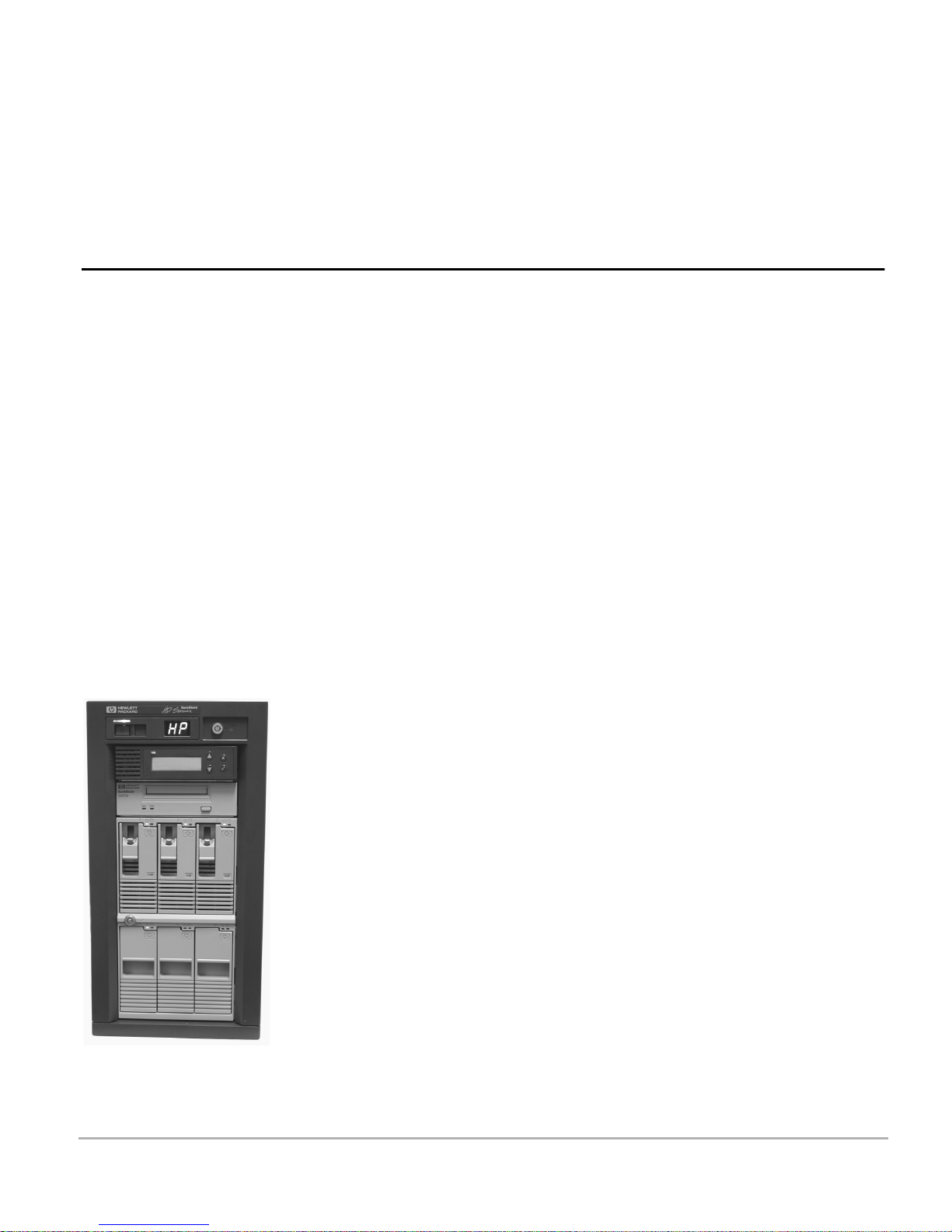
The HP SureStore HD Server 4000 Models
T
HP J3290A Contains three replaceable 9.1-gigabyte HP SCSI hard disk drive
modules, preconfigured as a RAID 5 volume, and three empty slots
for adding additional replaceable HP hard disk drive modules.
HP J3291A Contains three replaceable 9.1-gigabyte HP SCSI hard disk drive
modules, preconfigured as a RAID 5 volume, three empty slots
for adding additional replaceable HP hard disk drive modules,
and an HP DAT40 internal DDS-4 tape drive for local backups.
HP J3292A Contains six replaceable 9.1-gigabyte HP SCSI hard disk drive
modules, five preconfigured as a RAID 5 volume, one as a hot spare.
HP J3291A SureStore HD Server 4000
ape Drive
Hard disk modules
(3 in the upper cage)
Empty slots with
filler panel
(3 in the lower cage)
2-4 Installation
Page 21

Optional: Adding Modules
Use this section if you intend to add components to the
HP SureStore HD Server 4000 before you install it.
Installing Hard
Drive Modules
Installing
Internal Tape
Drive Module
Attaching
External Tape
Drive
Note ❏
The product numbers HP J3290A and J3291A have empty slots
accommodating up to three additional HP hard disk drive modules.
These drives can be used to expand the volume. (One of the additional
modules can be reserved as a hot spare.) Refer to chapter 7 for a list of
drive products available and the instructions for installation; then
return to this page to complete the server installation.
You may add an internal tape drive to any of the three product
numbers. (HP J3291A has a DAT40 drive already installed.) Refer to
chapter 8 for a list of tape drive products available and the
instructions for installation; then return to this page to complete
the server installation.
You may attach one external HP DAT or HP DLT drive to any
HD Server 4000. You may install both an external
tape drive. Refer to chapter 8 for a list of the tape products available
and the instructions for attachment; then return to this page to
complete the server installation.
The external tape drive attaches to the HD Server in place of
the preinstalled SCSI terminator. Ensure that a SCSI
terminator is attached to the end of the SCSI bus, usually on
the external tape drive. The terminator you remove from the
HD Server’s SCSI connector (HP part no. 5063-5324) may be
moved to the tape drive. Otherwise, you may use the SCSI
terminator block attached to the rear of the tape drive.
an internal
and
Optional: Rack Mounting
After you have installed any additional modules (as described in the
previous section), you can use the HP J1492B Rackmount Kit for
HP Storage System/6 to mount the server in any HP 19-inch rack.
Perform the rack mounting before attaching power or cables to the
HD Server.
Installation 2-5
Page 22

Preparation Checklist
10T_____ 100T_____
Autonegotiate?_____
DHCP/BOOTP
server__ • The server can use DHCP (Dynamic Host Configuration
IP addr____________
Mask______________
Gateway___________
2 power sources_____
Verify that a 10Base-T (Ethernet) or 100Base-TX
❏
(Fast Ethernet) network cable with an RJ-45 connector is ready
for the server.
Determine how the IP addresses are assigned on the network
❏
for the server. The HD Server provides the following choices.
Protocol) or BOOTP (Bootstrap Protocol) for automatic
assignment. For BOOTP service, configure the address for
the HD Server on your BOOTP server before proceeding.
For DHCP service, you may wish to assign a static address
to the HD Server, or you can allow dynamic IP assignment.
Consult your documentation for the service you select.
• Otherwise, the server must use manual IP address
assignment. In this case, determine the IP address, the
subnet mask, and the default gateway (router), if any.
Locate two power sources for plugging in both redundant power
❏
supplies on the server.
Power is off____
CAUTION!
Input Voltage____
100-127__ 200-240__
2 power cords____
Options installed____
Verify that the main power light above the power switch is
❏
(illustrated on page 2-7). If it is on, disconnect power.
Verify that the power supply input voltage is set according to
❏
the power standards in the country of use; set the two voltage
switches on the rear of the enclosure (see the rear view on
page 2-7) to 115 volts or 230 volts. Also verify that the power
cords are appropriate for the country of use (see page 2-3 for a
list).
Install any optional hardware: additional disk drives, tape
❏
drives, rack mounting. See “Adding Modules” on page 2-5.
off
2-6 Installation
Page 23
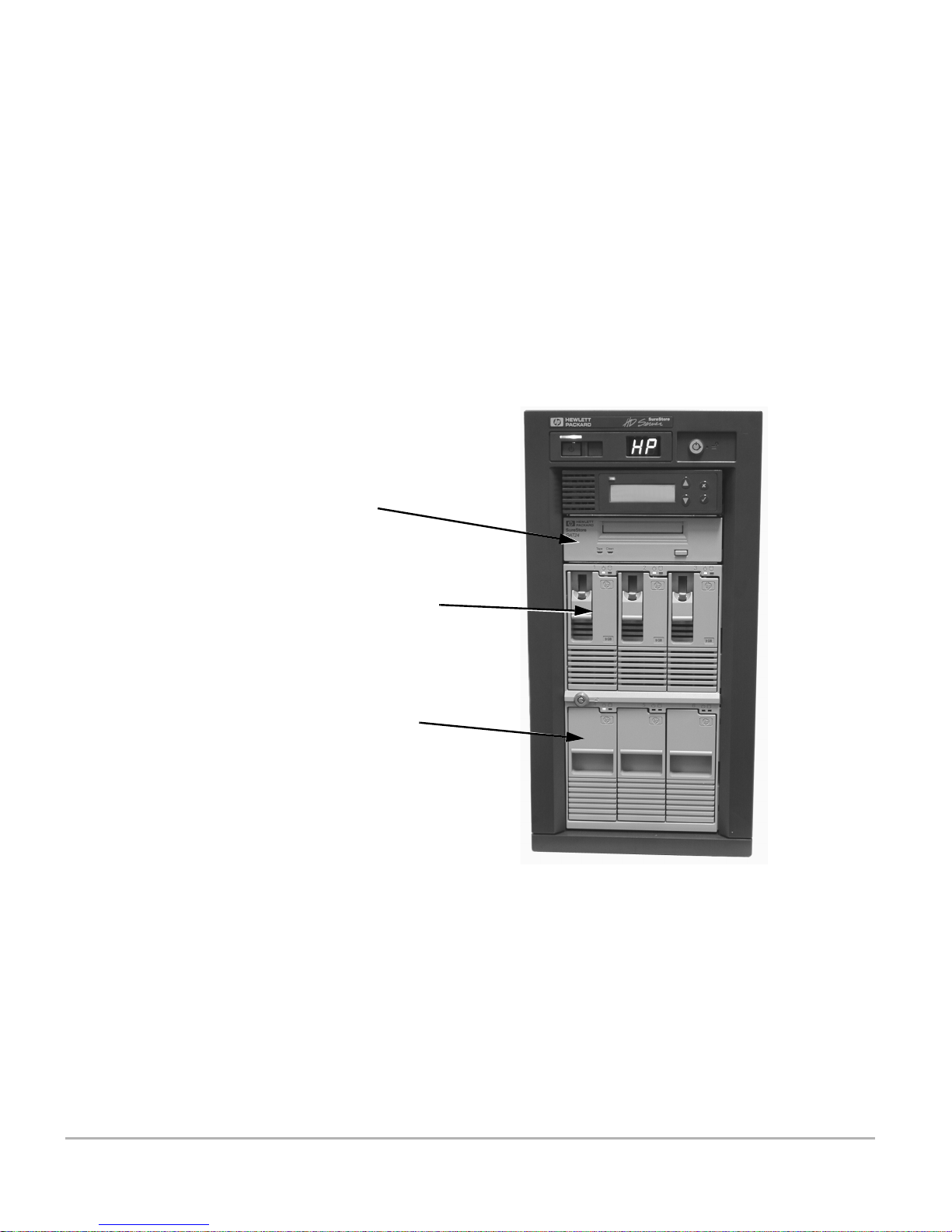
Rear View of HD Server
s
SCSI terminator,
or remove and attach
external tape drive
RJ-45 network connector
2 power plugs
2 voltage selection switche
Main power light
Power switch
Server module
Internal tape drive
Drive keylock
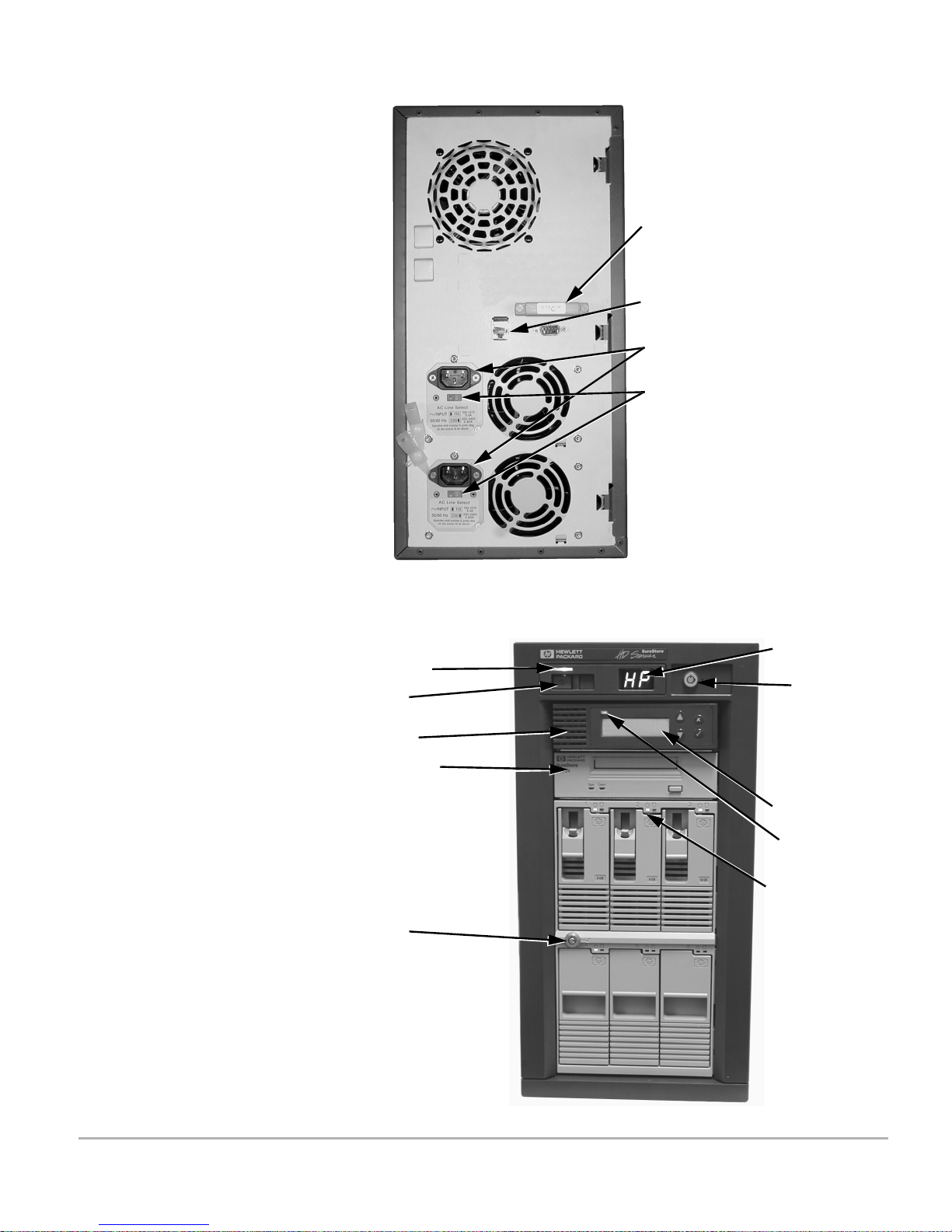
Front View of HD Server
Power display
Enclosure
keylock
Control panel
Link/activity
light
Drive power,
Drive activity
lights
Installation 2-7
Page 24

Connecting and Starting Up
Startup Steps
Note ❏
1. While the power is
connector on the rear of the server. (See the rear view
illustrated on page 2-7.)
If you have attached an external tape drive, now install its
power cord and switch on its power.
2. Attach the two power cords to the rear of the server and to power
outlets (preferably to separate power circuits). (See the rear view
illustrated on page 2-7.)
3. On the front of the server, switch on power. (See the front view
illustrated on page 2-7.)
4. Verify that:
• The main power light (LED) above the power switch is on
and the power display (2-character LED) displays HP.
• Drive power and drive activity lights (LEDs) blink to
indicate self-tests. The drive power light on each disk drive
module stays
• The control panel (LCD) displays self-testing and loading
messages.
, attach your network cable to the RJ-45
off
green
.
Note ❏
If you see any of the following exceptions to the verification
checks listed above, refer to chapter 11, “Resolving Problems
with Your Server”:
• Lights described above fail to go on.
• Power display shows LF or PF or FF.
• Control panel displays
• Control panel display remains unchanged for more than
ten seconds.
When you start up the server, its behavior depends on whether
you are installing it for the first time or have already installed
it before. The first time, it will behave as described in step 5
below; proceed with this procedure. If the behavior is different,
it has probably been started before; go to “Starting Up the
Server” on page 6-1 instead.
FAIL
or
FAULT
anywhere in the text.
2-8 Installation
Page 25

Control Panel
Setup
5. You will be prompted on the control panel for the IP configuration
method as follows. (The two displays alternate.)
Press
to use
✔
DHCP/BOOTP or...
Press
to set
✘
IP manually
Startup cannot continue until an IP address is set. Press one of
the following keys on the control panel to select the method of
assigning IP addresses on your network:
Assign IP Address
Automatically
• Press ✔ if the server IP address will be assigned on your
network using either DHCP (Dynamic Host Configuration
Protocol) or BOOTP (Bootstrap Protocol). See
“DHCP/BOOTP server” on page 2-6 for more information.
Startup of the server will continue until the server is active
on the network. Skip to step 11 on page 2-12 to verify
normal operation.
Assign IP Manually • Press ✘ if you will assign the server an IP address manually
at the control panel. This will place you in the control
panel’s setup mode.
6. Set the IP address manually at the next prompt:
IP Address
=000.000.000.000
The first character position on the second line of the display is
flashing. You may edit the digits one by one from left to right.
When a digit is flashing, you may:
• Increment each digit’s value (change it “up”)
by pressing▲.
• Decrement each digit’s value (change it “down”)
by pressing▼.
• Accept the digit by pressing ✔. This moves to the next digit,
unless it was the last digit.
• You may go back (left) by pressing ✘ for each digit until the
needed digit is flashing. Then press ▲ or ▼ to change it.
Note that if you press ✘ when the first digit is flashing,
you will cancel the setting of the entire parameter.
When the last of the 12 digits is flashing, pressing ✔ again
accepts the address setting displayed. The scroll symbol
returns to the first line of the display.
Installation 2-9
Page 26

Subnet Mask 7. Press ▼ to scroll down to the next parameter, the IP subnet mask.
The subnet mask determines what traffic should be sent to the
gateway and what traffic stays on the local segment. You will see
a default based on the class of IP address you set in step 6 above.
An example for class C is shown below:
Subnet Mask
=255.255.255.000
To change this parameter, press ✔ to select it. Then specify the
subnet mask in the same format and with the same procedure
as described for the IP address in step 6 above.
Default Gateway 8. Press ▼ to scroll to the next parameter, the default gateway
(default router) address. All traffic directed outside the local
network—according to the subnet mask (step 7 above)—is sent to
this default gateway. The default 000.000.000.000 specifies that
no default gateway is set.
Default Gateway
=000.000.000.000
To change this parameter, press ✔ to select it. Then specify the
gateway address in the same format and with the same
procedure as described for the IP address in step 6 above.
When the addresses are set up, you have configured the
minimum requirements to put the server on the network so that
you can make a remote connection and use the embedded web
interface to make further configuration changes before
providing client access.
2-10 Installation
Page 27

Optional:
Additional
Control Panel Changes:
Password,
Auto-Restart,
Link Speed
9. Refer to the table on page 3-6 for any setup changes you want to
make on the control panel. Examples of setup changes are:
• You may set a password to limit access to the control panel.
Set the
Change Password
parameter.
• You may want the server to automatically attempt to
restart following critical errors rather than halt and wait.
Set the
Auto Restart
parameter.
• If you must set a specific link speed or duplex mode, rather
than have them set automatically, set the
Link Speed
parameter.
Scroll to the desired control panel parameter. Use the following
buttons (as indicated by the scroll symbol in the top line of
the display):
to scroll “down” to the next parameter in the list
▼
to scroll “up” to the previous parameter in the list
▲
To select the parameter for modification, press ✔ (when the
scroll symbol is in the first line of the display).
No Further Control
Panel Changes
Use the ▲ and ▼ buttons to scroll through the choices of
settings (when the scroll symbol or flashing characters are in
the second line of the display) or to edit characters in the
setting. Press ✔ to accept the setting.
(A table listing the behavior of all the buttons is in “Control
Panel Reference” on page 3-1.)
10. Exit the control panel setup mode to proceed with server
initialization. Press ✘ to cancel; The following displays:
Exit Setup Mod
= Yes, ✘ = N
✔
e ?
o
Press ✔ to confirm the exit.
Note:
If your IP address, subnet mask, and gateway
settings (done in steps 6, 7, and 8 above) are inconsistent
when you attempt to exit, the error message shown below
displays for three seconds.
Gateway, Subnet
or IP invalid
In response, press✔ or wait for three seconds. Return to
one of the three addressing parameters to correct the
inconsistency (see page 2-9). If you do exit without
correcting the error, the server may be inaccessible on the
network.
Installation 2-11
Page 28

Verify Normal
Operating State
11. Startup of the server will continue until the file system is ready
and the server is available on the network for client access or for
further configuration. The following are indicators of normal
operation. Refer to the front view illustration on page 2-7.
• The main power light (above the power switch) is on.
• The drive power lights on operating drives are
green
and
the drive activity lights flash when data is read or written.
• The control panel displays the server name on the first line
and alternates on the second line between the date and
time, whether there are any alerts to read, and the
IP address. Examples:
HPHDSERV345ABC
Tue Jun 1 14:59
HPHDSERV345ABC
no alerts
HPHDSERV345ABC
192.168.001.001
It is
normal for the IP address to be 000.000.000.000.
not
The server is inaccessible over the network in this case.
The IP address is not shown if a control panel password has
been set.
Note the IP Address Make a note of the IP address displayed; it is needed in
subsequent steps.
• The link/activity light above the control panel display is
green
when the network link is established. It
blinks
for
each packet transmitted or received.
• The server is accessible over the network to client users
using standard network file system protocols. The server
can be administered using the embedded HD Server Admin
(with a web browser).
If your server deviates from the above conditions after it has
been set up, see chapter 11, “Resolving Problems with Your
Server”.
2-12 Installation
Page 29
Web Browser
Network Setup
To check and customize the server’s network and file system
configuration, you may use a web browser at another station on the
network. For further requirements and information, see “Using a
Web Browser on the Network” on page 4-1.
12. Start the browser. Refer to the server’s IP address you noted in
step 11, page 2-12. In the browser’s address field, you will include
the IP address (shown below as
<IP-address>
) in the URL of the
server:
http://
<IP-address>
If you configure a DNS name for this server on the DNS
server, you can use the name in place of
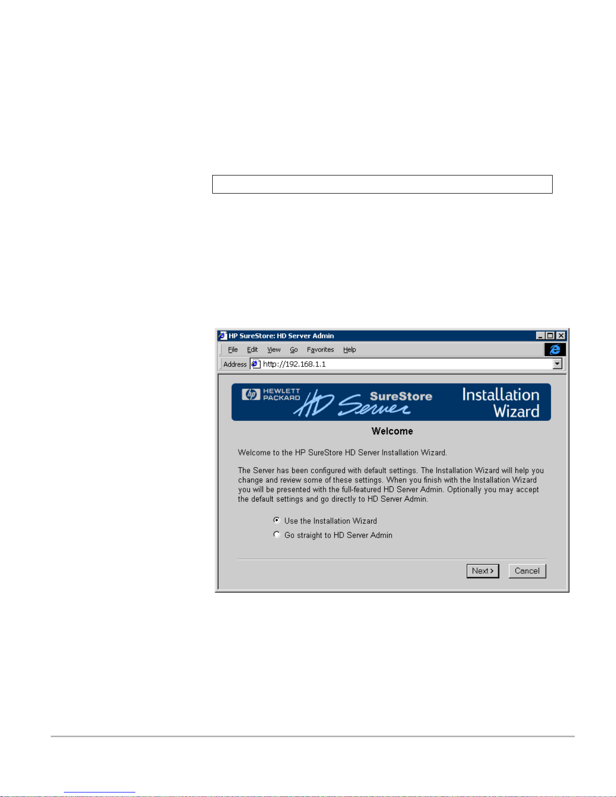
On the first page of the
Installation Wizard
<IP-address>.
shown below, you
are given the choice to bypass the wizard and go directly to
HD Server Admin (go to page 4-3) or to proceed with the
installation wizard, which is the quick and easy setup
procedure described here.
13. Allow the
to remain selected and click the
[Next>]
when finished with each
[Next>]
Installation Wizard
button to proceed. Click
page; you will be guided through the configuration parameters
used for most network environments.
Use the
[Help]
button for assistance on the pages.
Installation 2-13
Page 30
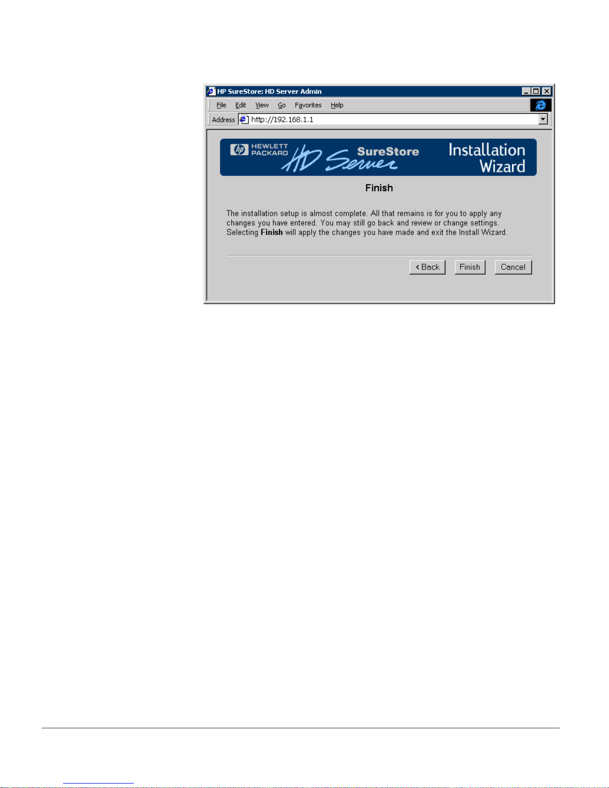
14. When you reach the
Finish
page, click the
Finish
the setup changes you have made and to exit the wizard.
• If the changes you have made in the wizard require
restarting the server (as server name and IP changes
require, for example), you will see a check in the box for
Restart Server
you click
Finish
. Allowing the box to remain checked when
causes the server to be restarted
immediately. After your server restarts, your web browser
should automatically reconnect to the server. The page
displayed will be the HD Server Admin’s
Identity
shown on page 4-3.
button to apply
page
2-14 Installation
• If you did not make changes that require restarting the
server, then your web browser immediately displays the
HD Server Admin’s
Identity
page shown on page 4-3.
15. Your next step depends on whether you need to further modify the
configuration and user setup. Meanwhile, the server is available
as configured by the wizard.
• If no more changes are required, you can skip to chapter 5,
“Setting Up Client Access”.
• If more configuration changes are required, you can make
them now in HD Server Admin. The following reference list
may help you decide.
Page 31

Optional: Further Configuration
Parameter Page in HD Server Admin Location in This
Microsoft Security Model:
User-level
Users
subordinate parameters)
Share Name
parameters)
Event Logging Threshold
Email Alerts Enabled ConfigurationÆAlertsÆEmail
SNMP Enabled,
GetCommunityName,
SetCommunityName
SNMP Alerts Enabled,
Authentication Alert Enabled,
TrapCommunityName,
TrapDestination[1-4]
Enable Automatic Server
Restart
and
and
Groups
(and subordinate
(with
SecurityÆMicrosoft Networking
ConfigurationÆUsers & Groups
ConfigurationÆFile Shares
ConfigurationÆAlertsÆEvent
Logging Threshold
ConfigurationÆNetworkÆSNMP
ConfigurationÆAlertsÆSNMP
ConfigurationÆGeneralÆ
Automatic Server Restart
“Share Level, User Level” on
page 4-10
“Set Up Users and Groups” on
page 4-11
“File Shares” on page 4-10
“Event Logging” on page 4-12
“E-Mail” on page 4-12
“E-Mail” on page 4-12
“Automatic Server Restart” on
page 4-5
User’s Guide
User
(Administrator username)
Backup Schedule Backup/RestoreÆSchedule
Shutdown and Restart ConfigurationÆShutdown/Restart
SecurityÆWeb UI
16. Register your HP NAS product now and receive:
• Technical support updates
• Special Hewlett-Packard offers
• Details on new products and technologies
Go to URL:
http://www.hp.com/go/surestore_nas
“Administrator Username and
Password” on page 4-5
“Specifying and Scheduling a
Backup” on page 9-4
“Restart the Server to Effect
Changes” on page 4-13
Installation 2-15
Page 32

Maintain Hardware Operation
Maintaining
Operating
Temperature
Notes ❏
WARNING!
Keeping the server within the range of normal operating
temperature (refer to appendix C) is necessary.
If the server has been exposed to temperature extremes, allow
two hours for it to stabilize to room temperature and humidity
before switching on the power.
Filler panels are preinstalled in your server to cover any unused
❏
disk drive module shelves. These panels must be installed on
shelves unused for modules for the product, to provide proper
cooling for the disk drive modules. If a filler panel is missing,
order the following replacement:
Hot-swap drive module slot cover 5063-8391
Do not block the cooling vents. Do not place the server closer
❏
than 6 inches to a wall.
To avoid the hazard of electrical shock and to ensure cooling
❏
functions, the side door must be closed while power is on.
Power and Temperature Status Indicators
CAUTION!
If FF is displayed on the power display, the enclosure’s cooling has
failed. Begin the shutdown procedure (see page 6-5) as quickly as
possible.
Continued operation of the server with a failed fan could result
❏
in loss of data or damage to the components.
The lights on the disk drive modules indicate the status of the two
cages (with three drive shelves each). All the lights in a cage will
flash yellow or red to warn you of power faults:
Flashing Yellow:
normal range.
Flashing Red:
the operating temperature range. Immediately begin the
shutdown procedure on page 6-5 and refer to chapter 11,
“Resolving Problems with Your Server”.
Temperature in this cage possibly exceeds
Temperature in this cage definitely exceeds
2-16 Installation
Page 33

Maintaining Tape
Drives
Tape drives must be cleaned regularly with a cleaning cartridge to
maintain the integrity of your backup data. If you installed the
HP SureStore tape drive, clean them as advised in the “Cleaning”
section in the electronic
CD-ROM
that accompanies your HP tape drive. If your
User’s Guide
on the
HP SureStore Tape
HP SureStore DAT drive was preinstalled, use the instructions in
this section.
Recommended Cleaning Frequency
Number of DDS Cartridges Used Each Day
1234+
Every 8 weeks Every 4 weeks Every 3 weeks Weekly
CAUTION!
CAUTION!
You should also clean the tape heads if the media caution signal
❏
(flashing amber
Clean
light) is displayed on the tape drive.
Cleaning Cartridges
Use only an HP cleaning cartridge to clean the tape heads.
❏
Do
use swabs or other means of cleaning the heads.
not
The cleaning cartridge uses a special tape to clean the tape heads.
A cleaning cartridge can only be used 50 times or as instructed on
the cartridge packaging. When the cartridge runs out of tape,
discard it and use a new one.
Cleaning Procedure
1. Insert a cleaning cartridge into the tape drive. The drive
automatically loads the cartridge and cleans the heads.
The cartridge ejects at the end of the cleaning cycle,
approximately 30 to 60 seconds. If the cartridge ejects in less
than 20 seconds, it has probably expired. In this case discard it
and repeat this step with a new cartridge.
2. Remove the cleaning cartridge from the tape drive and mark it
with the number of times it has now been used.
Discard it after you have used it 50 times, or as instructed on
the packaging.
Installation 2-17
Page 34

2-18 Installation
Page 35

Configuration Using the Control Panel
This chapter describes how to use the settings and functions of the
control panel in setting up your server. Once you have installed and
started or restarted the server according to instructions in
chapter 2 or 6, you can use these procedures.
Control Panel Reference
3
Buttons
Display
Symbols
▲
▼
✘
✔
=
Flashing
Digit
Up
For parameters, previous one in menu.
For numbers and letters, next one.
Down
For parameters, next one in menu.
For numbers and letters, lower one.
Cancel, or back up
OK and continue, or enter
Indicates current line to scroll using ▲ or ▼ button
in the first line indicates that ▲ and ▼ buttons will scroll
through the menu of parameters in the first line.
✔
selects this parameter to modify settings in the second line.
in the second line indicates that ▲ and ▼ buttons will scroll
through the menu of settings in the second line.
Indicates current setting
Indicates current digit or setting to change.
A flashing digit in the second line indicates that ▲ and ▼ buttons
will increment or decrement that digit or setting.
Configuration Using the Control Panel 3-1
Page 36

Accessing Control Panel Parameters
The primary modes for using control panel parameters are
view mode
setup mode,
(
Boot mode
, available from the normal operating state, and
available from the initialization state (see page 6-10).
has special uses for product code; see page 10-3.)
View Mode
You can use view mode for viewing the current settings, for reading
any alerts, for checking the link type, for changing the control panel
password, and for shutting down the server. While the server is
operating normally, you enter view mode by pressing the
on the control panel.
You will be prompted for the control panel password—if you have
set one. In that case, see “Supplying the Password for Access” on
page 3-3, and then return here.
The control panel display then alternates the following instructions
for entering view mode:
Use Ç or
to move up/down
Use ✘ to cancel
Use ✔ to select
Press any control panel button to proceed in view mode or wait
about 30 seconds. The settings are listed in the table on page 3-6.
For procedures that use the control panel, refer to the following:
È
key
button
✔
Setup Mode
For shutdown see chapter 6, “Shutting Down and Restarting”.
•
To check errors and alerts see chapter 11, “Resolving Problems
•
with Your Server”.
Enter setup mode to make changes to the server’s settings.
This happens automatically when installing the server for the
•
first time (see chapter 2) if you choose the manual method of IP
address setting. Proceed to page 2-9 for additional setup
procedures.
installing the server for the first time, you can get into
After
•
setup mode whenever you restart the server. During
initialization the control panel displays the following
countdown from 10 to 0 seconds for entering setup mode.
Press ✔ to enter
Setup Mode: 10
If you do
completed, then startup will resume.
not
press
before the countdown of 10 seconds is
✔
3-2 Configuration Using the Control Panel
Page 37

If you do press ✔ before the countdown of 10 seconds is
completed, you will be prompted for the control panel
password—if you have set one. In that case, see “Supplying the
Password for Access” on page 3-3, and then return here.
The control panel display then alternates the following
instructions for setup mode:
Supplying the
Password for
Access
Use Ç or
to move up/down
Use ✘ to cancel
Use ✔ to select
Press any control panel button or wait (about 30 seconds) to
proceed with setup mode.
The settings are listed in the table on page 3-6. For procedures that
use the control panel, refer to the following:
For shutdown see chapter 6, “Shutting Down and Restarting”.
•
To check errors and alerts see chapter 11, “Resolving Problems
•
with Your Server”.
You will be prompted as shown below for the control panel
password—if you have set one. (See
page 3-6.)
Enter Password:
The first character position on the second line of the display is
flashing. To specify each character you may:
È
key
Change Password
in the table on
Press ▲ (up button) on the control panel to cycle through each
•
letter of the alphabet and each digit.
Press ▼ (down button) on the control panel to cycle through
•
each letter and digit in the opposite sequence.
Accept the character by pressing ✔. The next character position
•
flashes. Specify that character in the same way.
You may go back (left) by pressing ✘ for each character until the
needed character is flashing. Then press ▲ or ▼ to change it.
When the password is complete, press ✔ at a blank character
position.
Configuration Using the Control Panel 3-3
Page 38

Setup Parameters and Procedures
Setting
Password,
Auto-Restart,
Link Speed
Refer to the table on page 3-6 for the setup changes you want to
make on the control panel. Examples of setup changes are:
You may set a password to limit access to the control panel. Set
•
the
Change Password
You may want the server to automatically attempt to restart
•
following critical errors rather than halt and wait. Set the
Restart
If you must fix a specific link speed or duplex mode, rather than
•
have them set automatically, set the
Scroll to the control panel parameter (the sequence is shown in
the table). As the scroll symbol in the top line of the display
indicates, use the following buttons:
To select the parameter for setting, press ✔ (when the scroll
symbol is in the first line of the display).
Use the ▲ and ▼ buttons to scroll through the choices of
settings (when the scroll symbol or flashing characters are in
the second line of the display) or to edit characters in the
setting. Press ✔ to accept the setting.
parameter.
to scroll “down” to the next parameter in the list
▼
to scroll “up” to the previous parameter in the list
▲
parameter.
Link Speed
Auto
parameter.
Refer to “Control Panel Reference” on page 3-1 for button
behavior.
3-4 Configuration Using the Control Panel
Page 39

Exiting the
Control Panel
To finish using the control panel view mode or setup mode, press ✘
to cancel. You will see one of the following displays:
Notes
for Setup
Exit Setup Mod
= Yes, ✘ = N
✔
e ?
o
Exit View Mod
= Yes, ✘ = N
✔
e ?
o
Press ✔ to confirm the exit.
If your IP address, subnet mask, and gateway settings are
❏
inconsistent when you attempt to exit from setup mode, the
error message shown below displays for three seconds.
Gateway, Subnet
or IP invalid
In response, press✔ or wait three seconds. Return to the three
addressing parameters to correct the inconsistency. If you do
exit without correcting the error, the server may be inaccessible
on the network.
When you exit setup mode, your changes are saved and take
❏
effect.
Startup of the server will continue until the file system is ready
❏
and the server is ready for client access. Verify that you see the
normal operating display on the front of the server, as described
in “Normal Operating State” on page 6-4.
Configuration Using the Control Panel 3-5
Page 40

Reference Table:
Parameter In Setup Mode In View Mode Description
Control Panel Parameters, Menus, and Settings
IP Method
IP Address
Subnet Mask
Default
Gateway
Link Speed
Settings menu:
Manual
DHCP/BOOTP
*
Edit the default:
*
‡
000.000.000.000
Edit the default:
255.255.255.000
*
‡
(for example)
Edit the default:
000.000.000.000
*
‡
Settings menu:
Auto (default)
10 Half
10 Full
100 Half
100 Full
*
Show setting only Selects the mechanism for determining the IP
address, subnet mask, and default gateway.
Show setting only The Internet address of the server. The default
setting 000.000.000.000 is an illegal IP address.
Show setting only Determines when the traffic is directed through a
gateway. The default you see depends on the class
of IP address that is set (example is class C).
Show setting only Address of the default router or gateway, through
which all traffic directed outside the local network
(according to the subnet mask) is directed. The
default is that no default gateway is set.
You can view the actual speed & duplex mode
Show detected
speed followed by
current setting:
… (Auto)
… (10H)
… (10F)
… (100H)
… (100F)
No link
detected, followed by current setting in
parentheses, e.g. 100 Half (Auto). Meaning of
settings:
Autodetect and set network speed & duplex mode.
(10H)Fix speed to 10Base-T, half duplex.
(10F)Fix speed to 10Base-T, full duplex.
(100H)Fix speed to 100Base-T, half duplex.
(100F)Fix speed to 100Base-T, full duplex.
The setting is not in effect: network not connected!
Auto Restart
Alerts Viewer
MAC address Show setting only
Firmware Ver. Show setting only Show setting only Displays the running firmware version
ROM Version
Reset
Defaults
Change
Password
Settings menu:
On
*
‡
*
‡
Off
(default)
Not available
in setup mode
(set at factory)
Show setting only Show setting only Displays the firmware version of the boot ROM
Prompt:
Press ✔ to begin
Prompt:
Press ✔ to begin
marks parameters affected by Reset Defaults
marks parameters also set using HD Server Admin, the embedded administration tool
Show setting only Specifies whether the server will automatically
restart (up to 3 times) after a critical error, or
whether it will halt.
Show list only
no Alerts
(default)
Show setting only Displays the hardware (LAN) address of the
Not available in
view mode
Prompt:
Press ✔ to begin
Displays a list of scrolling alert messages. Alerts
can be cleared by pressing ✔.
server.
code.
Sets some parameters on control panel (
HD Server Admin to defaults for first installation.
Allows you to specify a control password to control
access to these menus.
) and in
*
3-6 Configuration Using the Control Panel
Page 41

Parameter In Setup Mode In View Mode Description
Shutdown
Server
Exit
Setup/View
Mode
Prompt:
Press ✔ to begin
‡
Prompt:
Press ✔ to begin
*
marks parameters affected by
‡
marks parameters also set using HD Server Admin, the embedded administration tool
Prompt:
Press ✔ to begin
Prompt:
Press ✔ to begin
Reset Defaults
Shuts down file services. This allows you to safely
switch off power or insert drives.
In setup mode, allows server initialization to
complete first, then go to normal operational
display. In view mode, returns to normal
operational display.
Configuration Using the Control Panel 3-7
Page 42

3-8 Configuration Using the Control Panel
Page 43

Configuration Using a Browser: HD Server Admin
Using a Web Browser on the Network
The configuration and management tool embedded in the
HD Server 4000 is HD Server Admin. You access it using a web
browser at another computer on the network, once you have
configured the IP address of the server (step 5 on page 2-9).
Network
4
Client
Client
HP SureStore HD Server
You can use Microsoft Internet Explorer version 4.0 or later or
Netscape Navigator version 4.06 or later. It is recommended, but
not required, that you enable active scripting or JavaScript to take
advantage of all the display features of the interface.
1. Start the browser.
2. Refer to the server’s IP address you see displayed on the control
panel or that you noted during installation. In the browser’s
address field, you will include the IP address (shown below as
<IP-address>
) in the URL of the server:
Administrator’s PC + web browser
http://
If you have configured a DNS name for this server on the DNS
server, you can use the DNS name in place of
<IP-address>
<IP-address>.
Configuration Using a Browser: HD Server Admin 4-1
Page 44

3. The HD Server Admin page for that server is displayed. If the
server is being installed for the first time, you will see the
Installation Wizard
page.
Note ❏
If you are starting the server
the
Identity
page shown under “Setup with HD Server Admin”
the first time, you will see
after
on page 4-3.
If the server is not found, check the following:
• An IP “ping” command done on a remote station can reach
the IP address assigned to the server.
• The IP address used in the URL in step 2 on page 4-1 is the
same one configured onto the server, except with the
leading zeroes omitted. Check the control panel.
• The link/activity light above the control panel display (see
page 2-7) is lit to show a link established.
• The
Link Speed
setting established,
parameter on the control panel shows a
“No link”.
not
• The IP address, mask, and gateway assigned to the server
are legitimate for the subnet used.
See also chapter 11, “Resolving Problems with Your Server”.
4-2 Configuration Using a Browser: HD Server Admin
Page 45

Setup with HD Server Admin
You can change configuration and monitor and administer the
server using the HD Server’s embedded web tool named HD Server
Admin. This chapter focuses on the tasks you can do with the tool.
All configuration tasks can be done using this utility, except for the
configuration settings found only on the control panel:
Password
To access this tool, use the procedure “Using a Web Browser on the
Network” on page 4-1.
for the control panel, and
Reset Defaults
Link Speed,
.
Initial Page
Identity
HD Server Admin starts with the display of the
shown below. If the display starts with the
instead, go to page 2-13.
page
Installation Wizard
Identity
page,
Configuration Using a Browser: HD Server Admin 4-3
Page 46

Operating
Features of
HD Server Admin
The web pages served are created with the information current at
the time the page is first displayed or is refreshed.
The server name and status are shown at the top of the page.
Beneath those items, parameters are available after selecting
(1) among the tabs across the top of the page. Under some tabs you
then select (2) among buttons in a row under the tabs. After
selecting some buttons, you select (3) among items menued in a
column at the left side of the page. The new page presents the
parameters. In this manual, the series of selections required to
reach the parameters is shown as “
System Information
”, for example.
Configuration Æ General Æ
(1)
(2)
Note:
Restart May Be
Required
(3)
Where available, you may use the
[Help]
button to access help for
the parameters on the page.
Use the
[Apply]
not be replaced nor the window closed, or use the
button to save changes to the server; the page will
button (on
[OK]
some invoked windows) to save changes and close the window.
Some changes require that the server be restarted to take
❏
effect. These include the server name, TCP/IP settings,
Windows networking settings and security model. If the
response to any of your changes states the need for a restart,
use
Shutdown and Restart
Shutdown/Restart
page when all changes are complete. See
on the
Configuration
Æ
“Restart the Server to Effect Changes” on page 4-13.
4-4 Configuration Using a Browser: HD Server Admin
Page 47

This section describes configuration tasks that you may need, either
before or after making the server available to clients.
Server Name
Date and Time
Automatic Server
Restart
Configuration Æ General Æ System Information
By default, the server name is “HPHDSERV
“
hhhhhh
or hardware address). You may change this name for your server,
which is used to advertise the system on the network. This setting
takes effect after the next restart (see page 4-13).
You can also fill in other contact information on this page so that it
will be available to all clients who view the
(illustrated on page 4-3) and to some remote management
applications or services (see “SNMP” on page 4-12).
Configuration Æ General Æ Date & Time
Accurate time keeping is critical for accurate file backups and
version control. Note that the
Time
offsetting them from GMT.
Configuration Æ General Æ Automatic Server Restart
By default, if a critical error halts the server, a message is displayed
on the control panel instructing you to press ✔ to restart.
” are the last six digits of the server’s MAC address (LAN
page
Time Zone
settings affect the display of
Date
and
and
page
hhhhhh
Identity
Daylight Savings
Time
” where
page
settings by
page
Administrator
Username and
Password
You may enable automatic restart so that the server will restart
automatically, if possible. An alert will still be sent to notify you of
the event. Note that consecutive auto-restarts are limited; when
three occur, the server remains halted in any case.
Security Æ Web UI
On the
access to HD Server Admin (except the
This password is not related to the optional password for the control
panel.
By default, no password is set, so a username and password are not
required for access. Once you set a password, the username and
password will be required for access to HD Server Admin (except
the Identity and Support pages).
The default username that accompanies the password is
“
administrator
Web Console Password
page
page, set a password to secure
”. You may change it.
Identity
and
Support
pages).
Configuration Using a Browser: HD Server Admin 4-5
Page 48

Network
Configuration
Configuration Æ Network Æ TCP/IP
Changes to all parameters on this page take effect after the next
page
restart (see page 4-13).
IP Addressing You may manually specify the IP address, the subnet mask, and the
default gateway (router), or you may have them assigned
automatically by a DHCP or BOOTP server.
The assignment method and addresses are not defaulted. They
must be specified at the control panel when the server is started for
the first time.
DNS For domain name resolution for e-mail and SNMP notification,
configure the name of the domain, and specify the address of the
primary domain name server, and the secondary if needed. This is
not set by default.
Note ❏
You must manually add a DNS entry for this server in your
DNS database if you wish to access it by the server name rather
than IP address.
Configuration
Network Æ Microsoft Networking
Æ
page
Changes to all parameters on this page take effect after the next
restart (see page 4-13).
Workgroup or
Domain
For the
Workgroup/Domain
name setting, configure the name of
the workgroup or Windows NT domain (whichever you are using)
for the server. The default is the workgroup “
WORKGROUP
”.
If you are using an NT domain, in addition to its name also specify
the Windows name and address of the primary domain controller
(PDC). This is needed for services such as DHCP and WINS.
Note ❏
If you are using
this
Workgroup/Domain
Passthrough Authentication
setting must contain the name of the
(see page 4-11),
NT domain corresponding to the authentication server specified
in the
Server Name
and
Server IP
address settings.
Microsoft WINS You can enable and specify the IP address of a Microsoft Windows
Internet Naming Service (WINS) server. It is not set up by default.
The
NetBIOS Node Type
setting of
(For the SNMP configuration, see page 4-12.)
4-6 Configuration Using a Browser: HD Server Admin
Enable WINS
is defaulted to a setting appropriate to the
. A change is usually not required.
Page 49

Set Up Disks
Configuration Æ Disk Setup
page
Volume is
Preconfigured
By default, the hard disk drives installed at the factory are built
into a RAID 5 array—a single volume named “c”. For the
HP J3290A and HP J3291A products, this consists of 3 drives; for
the HP J3292A product, this consists of five of the six drives.
The diagram on the
Disk Setup
connected with solid lines into
page shows all drives in the array
Volume C
. (For the HP J3292A
product, the sixth drive, as a hot spare, is connected with a dotted
line into the volume.) You can click on an individual drive to get
status information for it. Using the
[Help]
button on this page is
highly recommended, especially to derive all the status information
available.
On this page you can add or change the role of disk drives as
described in the following sections.
Configuration Using a Browser: HD Server Admin 4-7
Page 50

Add Disk Drives to
the Volume
First perform the installation steps in chapter 7, “Adding Hard
Disk Drives”, to install the drive modules in the server and to
restart the server.
Note ❏
Add a Disk Drive as
the Hot Spare
On the
Disk Setup
and click the
available, select all to be added. Click
selections are correct and click
page, select the volume or an unused disk drive
[Expand Volume]
button. If multiple drives are
. Confirm the
[Finish]
[Next>]
.
Any previous contents of the added drives will be lost when they
are reformatted.
The data in the volume will be redistributed over the increased
number of drives. This may take one or two hours to complete. The
volume will be on line—accessible to the administrator and
clients—during this time. However, file access may be slower.
On the diagram, the added drives will be connected to the volume
with solid lines.
Only one drive can be configured as a hot spare.
First perform the installation steps in chapter 7, “Adding Hard
Disk Drives”, to install the drive module in the server and to restart
the server.
On the
[Add Spare]
Disk Setup
button to make it the spare drive. Click
the selection is correct and click
page, select the unused disk drive. Click the
. Confirm
[Finish]
[Next>]
.
On the diagram, the hot spare will be connected to the volume with
a dotted line.
Once you have added the hot spare as described in this section,
there are two alternatives for using it in the volume:
If a drive that is part of the volume should fail, the spare disk
•
drive automatically will be activated and will replace the failed
disk drive. This takes place without interrupting service to
clients. On the diagram, the status of the drive will be shown as
failed. Replace it at a convenient time using this same
procedure, “Add a Disk Drive as the Hot Spare”.
You may change the installed disk drive from its role as a spare
•
to become part of the volume, using the following procedure,
“Add the Spare to the Volume”.
In both cases, you will no longer have the extra redundancy of a
spare in case of a drive failure.
4-8 Configuration Using a Browser: HD Server Admin
Page 51

Add the Spare to the
Volume
Once you have added the spare as described in the previous section,
“Add a Disk Drive as the Hot Spare”, you can change its role to be
part of the volume. However, this drive will no longer provide the
extra redundancy of a spare in case of a drive failure.
Delete and Recreate
the Entire Volume
CAUTION!
On the
Configuration
Click the
Click
[Next>]
Disk Setup
Æ
[Expand Volume]
button to add it to the volume.
. Confirm the selection is correct and click
page, click the spare disk drive.
[Finish]
.
The data in the volume will be redistributed over the increased
number of drives. This may take one or two hours to complete.
The volume will be on line—accessible to the administrator and
clients—during this time. However, file access may be slower.
You may want to delay client usage of the server until finished.
The added drives will be connected to the volume with solid lines.
You may need this procedure if you redeploy the server or need to
rebuild the volume entirely.
To delete the volume means to destroy all the file data, along
❏
with the event log and the configured information on shares,
users, groups, and passwords. Click the
Configuration
Disk Setup
Æ
page for more information on the
[Help]
button on this
effects. Make sure you have backed up important data.
To delete the volume, click
Volume C
and click the
[Delete]
button.
Perform the requested confirmations carefully. The server will
automatically restart. HD Server Admin will be temporarily
disconnected until the restart completes.
Once you are viewing this
Configuration
Disk Setup
Æ
page after
the volume has been deleted, the disk drives will appear unused
and no volume icon will be displayed.
You can create the volume when it has been deleted. There can be
only one volume and it must have at least three disk drives. Click
on the
[Create Volume]
button. By default, all disk drives are
selected. If you want to exclude any of the disk drives from the
volume, deselect each one. If you have more than three selected, you
are given the option of using one as the hot spare. Perform the
requested confirmations.
The diagram will show all selected drives in the array connected
with solid lines into the volume, and any spare connected with a
dotted line.
Configuration Using a Browser: HD Server Admin 4-9
Page 52

Set Up Shares
Security Æ Microsoft Networking
page
Share Level,
User Level
Note
File Shares By default, the “
Permissions Use the
By default,
Level
here. The setting takes effect after the next restart (see page 4-13).
The settings of associated parameters such as users, groups, and
shares are saved when you switch security types. These settings
will reappear if you switch back to
User Level
Configuration Æ File Shares
access without a password. You may edit its permissions.
Use the
and paths. If the folder does not exist, you may create it. (You may
also create a share for the entire volume “c”, to include all the
shares, for administrative use if you wish.)
To specify the share permissions when using share-level security
(which is set on the
described above), you specify full-access passwords and read-only
passwords for each share.
security rather than
Security Model
.
[Add]
[Permissions]
for Microsoft networking is set to
User Level
page
” share is provided on the HD Server, with full
pub
button to add other shares and specify their names
button to change a share’s permissions.
Security Æ Microsoft Networking
security. You may change it
Share Level
and then back to
page, as
Share
To specify the share permissions when using user-level security
(which is set on the
described above), you specify the users and groups for each share
and what type of access they have, as follows.
No Access
•
Read
•
Change
•
Full Control
•
Security
No share access for the user or group
Read files in the share
Read, add, modify, and delete files in the share
Read, add, modify, delete, and change permissions
to files in the share
Microsoft Networking
Æ
page, as
4-10 Configuration Using a Browser: HD Server Admin
Page 53

Set Up Users
and Groups
Configuration Æ Users & Groups
page
When user-level security for Microsoft networking is configured,
use this page to create the users and groups for the server. This
page is inaccessible when the default share-level security is
configured. (See “Share Level, User Level” on page 4-10 above.)
Group member lists set up on this page can be used in granting
permissions to file shares. (See “Permissions” on page 4-10 above).
For each client user, specify the user name, the full name, and any
group memberships. In addition, you may specify each user
password here, or you may pass through the authentication to a
domain controller by enabling pass-through authentication.
Passthrough Authentication
requires further configuration, as
described immediately below.
Pass-through
Authentication
Note ❏
Configuration
Network
Æ
Microsoft Networking page
Æ
Pass-through authentication on the HD Server allows you to use a
domain controller as an authentication server—to validate the user
passwords on this server—so that you need not specify each
password in both locations.
On the HD Server, pass-through authentication does
not
use
the users and groups configured on an authentication server
(domain server). Users and groups must be configured on this
server using the
Configuration Æ Users & Groups
page (above
on page 4-11).
For pass-through authentication of users to be in effect, you must
do all the following:
Specify the name and IP address of the Windows NT domain
•
controller (authentication server) on this
Microsoft Networking
page.
Set up the usernames and passwords on that domain controller.
•
(This may already exist.) The usernames must be identical on
that domain controller and on this HD Server.
•
•
These settings take effect after the next restart (see page 4-13).
Enter the name of the domain for that domain controller and
this server into the
Workgroup/Domain
Configuration Æ Network Æ Microsoft Networking
field on the
page. (See
“Workgroup or Domain” on page 4-6.)
Enable
using
[Create]
Passthrough Authentication
or
[Edit]
on
Configuration Æ Users & Groups
on the
page, accessed
User
page.
Configuration Using a Browser: HD Server Admin 4-11
Page 54

SNMP
Configuration Æ Network Æ SNMP
page
By default, SNMP is enabled on the HD Server.
Get, Set Once SNMP is enabled, configure the SNMP agent on this server by
specifying up to two community names for
get
and
operations.
set
Traps By default, alerts for this server appear on its control panel, appear
Event Logging
Configuration
Alerts Æ SNMP
Æ
page
as events in HD Server Admin (see “Check Events” on page 4-14),
and are enabled—sent as SNMP traps to network management
tools such as HP TopTools and HP OpenView. Some additional
events (such as restarts) are also sent through SNMP as traps.
If you wish traps for this server to be sent to a management station,
ensure that SNMP is enabled, enter the community name to be
used, and specify each management station to receive the traps by
its IP address.
If a DNS server is configured on the
Network Æ TCP/IP
page, you may specify the management
Configuration
Æ
station by its DNS name, as long as the management station is
currently accessible on the network.
Configuration Æ Alerts Æ Event Logging Threshold
page
Server events are recorded in the event log (available on the
StatusÆ Event Log
most to least serious, the ratings are
Continuation
Warning
. By default, the threshold for reporting the events is
, that is, events with a seriousness of
are recorded, and events of less seriousness (
Continuation
) are not recorded in the log.
page), based on their seriousness rating. From
Panic, Warning, Notice,
Panic
Notice
and
and
and
Warning
E-Mail
E-mail Notification
of Alerts
Configuration Æ Alerts Æ Email
By default, alerts for this server appear on its control panel, appear
as events in HD Server Admin (see “Check Events” on page 4-14),
and are enabled as SNMP traps for viewing by network
management tools such as HP OpenView and HP TopTools.
If you wish any alerts for this server to also be sent as e-mail to the
administrator, then enable
by its IP address.
If a DNS server is configured on the
Network Æ TCP/IP
its DNS name, as long as the server is currently accessible on
the network.
4-12 Configuration Using a Browser: HD Server Admin
page
Email Alerts
, specify the e-mail server
Configuration Æ
page, you may specify the e-mail server by
Page 55

Set Up Backup
Schedule
Backup Æ Schedule
Backup
If an internal DAT tape drive is installed in the server or if an
external tape drive is attached directly to the server (see chapter 8,
“Adding a Tape Drive”), then use these backup pages to back up
files stored on the server (as described in chapter 9, “Backing Up
and Restoring Files”).
Backup
Æ
page
page
Back Up Changes
Restart the
Server to Effect
Changes
Configuration Æ Save/Restore Configuration Æ
Save Configuration
After you have made configuration changes, you should always use
this page to store the new server and network configuration
information on the volume for backup along with the file system
configuration information and the data files. You can do this either
before or after restarting the server if necessary (see “Restart”
below).
To make the backup for disaster recovery, see “Making a Disaster
Recovery Backup Tape” on page 9-7.
Configuration Æ Shutdown/Restart
Many configuration changes, though they have been applied using
[Apply]
can perform the restart by selecting
page. HP Server Admin will be unavailable until the restart
completes. See “Restart Procedures” on page 6-6 for more
information.
, require the server to be restarted before taking effect. You
page
page
Shutdown and Restart
on this
Configuration Using a Browser: HD Server Admin 4-13
Page 56

Monitoring Status with HD Server Admin
Check Status
Identity
page
The server name, product name, and the status of the server are
shown at all times at the top of the HD Server Admin web pages,
above the tabs. Use the
[Help]
interpretation of all the data available to you. The
button, where available, for full
Identity
page, the
initial page shown in HD Server Admin, also has some basic
information such as server name and IP address.
Status
Summary
Æ
page
For the detailed status of the components of your server, click on
each module on the server graphic: the disk drive modules, the tape
module, and the server module (click on the display panel to select
the server module).
Configuration
Disk Setup
Æ
page
For the detailed status of each disk drive as well as the volume and
file system, use the
slot. Click on
Volume C
Disk Setup
.
page. Click on each drive in each
Check File System
Check Events
Check Backup
Schedule and Log
In the
Volume C
view on the
Configuration
Disk Setup
Æ
page (see
previous paragraph), check the file system for errors by clicking the
volume and the
, users will be disconnected while the file system check is
[Yes]
[Check Volume]
button. When you confirm with
performed. Check the event log for results (see the next paragraph).
Status Æ Event Log
page
The event log is displayed on this page. You can control the
seriousness threshold for the events that are recorded in the log
using the
Configuration
AlertsÆEvent Logging Threshold
Æ
page
(see “Event Logging” on page 4-12).
Backup/Restore Æ Schedule
Backup/Restore
Use the
Backup Schedule
Æ
Log
page
page
page and the
Backup/Restore Log
page
to maintain and verify your backup process that uses the internal
and external tape drives.
4-14 Configuration Using a Browser: HD Server Admin
Page 57

Setting Up Client Access
The procedures used at client workstations on the network to access
the HP SureStore HD Server 4000 are the same as for other
Microsoft Windows 95, 98, or NT workstations and file servers. For
easy access to the file system from client applications, the server’s
shares can be made available to each client system—“mapped” to a
drive letter. After the share is mapped, the client accesses the
server just as any other networked file server.
The client operating systems supported are Microsoft Windows 95,
98, and NT 4.0.
5
The directories available to a client user depend on the shares,
security model, groups, and permissions that you set up using
HD Server Admin (see chapter 4). Clients can map to one of the
shares.
If you have made no changes in HP Server Admin, the default share
is named “
(share-level security without a password).
The server will be available on the network as soon as initialization
is complete and it is in the normal operating state (see page 6-4).
”, to which all connecting client users have full access
pub
Setting Up Client Access 5-1
Page 58

Map Drive
For mapping, you need the IP address or server name of the
HD Server, the share name, and either the share password
(configured for share level) or the user name and password
(configured for user level).
1. Look in Network Neighborhood for the server:
Find it in the domain or workgroup defined in the setup of the
installation wizard or HD Server Admin. The default location is
the
Workgroup/Domain
If that is the same workgroup or domain as the remote
workstation you are using, the server will also be listed at
the same level as the “Entire Network”.
named “
WORKGROUP
”.
The default server name is “HPHDSERV
“
hhhhhh
” are the last six digits of the server’s MAC address
hhhhhh
” where
(LAN or hardware address). The server name may have been
changed using the installation wizard or HD Server Admin.
If you need to find a specific server’s MAC address, use view
mode on the server’s control panel. See page 3-2.
2. Use Windows’ Map Network Drive function to map the user’s
share.
a. Select the drive letter.
b. For the path, use the Universal Naming Convention:
\\<server>\<share>
where
and
the
share is “
c.
For Windows NT only:
<server>
<share>
File Shares
pub
is either the server name or IP address
is the alias for the physical path defined on
page in HD Server Admin. The default
”.
5-2 Setting Up Client Access
• If the user-level security model is in effect (see “Set Up
Shares” on page 4-10), for “
Connect As
the name configured for User on the
Users & Groups
pages (described on page 4-11) in
” you need to use
Configuration
Æ
HD Server Admin—if the name and password are
different from those used for the workstation login
account.
• If the share-level security model is in effect (as it is by
default), then ignore “
Connect As
”.
Page 59

d.
For Windows NT, 95, 98:
Use the password as follows:
• If the user-level security model is in effect (see “Set Up
Shares” on page 4-10), then the password is configured
on the
Configuration Æ Users & Groups
pages in
HD Server Admin (as described on page 4-11). If the
password is the same as that used for the workstation
login account, it need not be specified.
If pass-through authentication is in effect with userlevel security, then the password is configured on the
domain controller (which is specified on the
Configuration Æ Network Æ Microsoft Networking
page in HD Server Admin as described above on
page 4-6).
• If the share-level security model is in effect (as it is by
default), then the password is configured on the
Configuration Æ File Shares
page in HD Server Admin
(as described above on page 4-10).
Setting Up Client Access 5-3
Page 60

5-4 Setting Up Client Access
Page 61

Shutting Down and Restarting
Use this chapter when you are starting up, or shutting down, or
restarting the server
start the server for the first time, refer instead to one of the
following:
the first time you started it. When you
after
6
Startup Steps
Quick Setup
•
“Connecting and Starting Up” on page 2-8
•
sheet
Starting Up the Server
1. Attach the two power cords to the rear of the server and to
power outlets (preferably to separate power circuits).
2. On the front of the server, switch on power. (See the front view
illustrated on page 6-2.)
3. Verify that:
• The main power light (LED) above the power switch is on
and the power display (2-character LED) displays HP.
• Drive power and drive activity lights (LEDs) blink to
indicate self-tests. The drive power light on each disk drive
module remains
• The control panel (LCD) displays self-testing and loading
messages.
green
.
Note ❏
If you see any of the following exceptions to the verification
checks listed above, refer to chapter 11, “Resolving Problems
with Your Server”.
• Lights described above fail to go on.
• Power display shows LF or PF or FF.
• Control panel displays
• Control panel remains unchanged for more than 10 seconds.
or
FAIL
FAULT
Shutting Down and Restarting 6-1
anywhere in the text.
Page 62

Front View of HD Server
Main power light
Power switch
Server module
Internal tape
drive
Drive keylock
Power display
Enclosure
keylock
Control panel
Link/activity
light
Drive power,
Drive activity
lights
4. The next display on the control panel depends on whether this is
the first time the server has been started:
• If this is the first time, refer to the
Quick Setup
sheet or to
“Connecting and Starting Up” on page 2-8.
• If this is
the first time, the control panel will display the
not
following countdown from 10 to 0 seconds.
Press ✔ to enter
Setup Mode: 10
If you wish to alter the configuration or operation of the
server at this time, press
before the countdown of
✔
10 seconds is completed. You will enter the control panel’s
setup mode. See step 5 below.
If you do
wish to alter the configuration or operation of
not
the server, do nothing and skip to step 7 below.
6-2 Shutting Down and Restarting
Page 63

5. If you do press ✔ before the countdown of 10 seconds is completed,
you will be prompted for the control panel password if you have
set one. (See “Change Password” in the table on page 3-6.)
Enter Password:
The first character position on the second line of the display is
flashing. To specify each character, you may:
• Press ▲ (up button) on the control panel to cycle through
each letter of the alphabet and each digit.
• Press ▼ (down button) on the control panel to cycle through
each letter and digit in the opposite sequence.
• Accept the character by pressing ✔. The next character
position flashes. Specify that character in the same way.
• You may go back (left) by pressing ✘ for each character until
the needed character is flashing. Then press ▲ or ▼ to
change it.
When the password is complete, press ✔ at the first blank
character position.
6. The control panel display alternates the following instructions for
setup mode:
Use Ç or
È
key
to move up/down
Use ✘ to cancel
Use ✔ to select
Press any control panel button to proceed with setup mode, and
refer to page 3-1 for more information on control panel usage.
Return to step 7 below after you complete the setup mode tasks.
7. Startup will continue until the server is ready for normal
operation, which is described on page 6-4.
During this time, the server establishes the link speed—10 or
100 megabits per second—and duplex setting—full or half—to
match the attached network.
Shutting Down and Restarting 6-3
Page 64

Normal Operating State
When the server has been initialized and the file system is ready,
the server is ready for client access or for further configuration.
The following are indicators of normal operation. Refer to the front
view illustration on page 6-2.
The main power light above the power switch is on.
•
The drive power lights on operating drives are
•
drive activity lights flash when data is read or written.
The control panel displays the server name on the first line and
•
alternates on the second line between the date and time,
whether there are any alerts to read, and the IP address.
Examples:
HPHDSERV345ABC
Tue Jun 1 14:59
HPHDSERV345ABC
no alerts
HPHDSERV345ABC
192.168.001.001
It is normal for the IP address to
password is currently set.
It is
server is inaccessible in this case.
The link/activity light above the control panel display is
•
when the network link is established. It
transmitted or received.
normal for the IP address to be
not
not shown if
password is set
be shown if a control panel
not
000.000.000.000
blinks
green
and the
for each packet
. The
green
The server is accessible over the network to client users using
•
standard network file system protocols. The server can be
administered using the embedded HD Server Admin (with a
web browser). For network setup and administration refer to
chapter 4. For client access see chapter 5, “Setting Up Client
Access”.
If your server deviates from the above conditions after it has been
set up, see chapter 11, “Resolving Problems with Your Server”.
6-4 Shutting Down and Restarting
Page 65

Shutting Down, Restarting, Cycling Power
The various types of restarting described in this section contain
references to operating states as described on page 6-10.
CAUTION!
Shutdown
Procedures
Note
Switching the server’s power
❏
appropriate shutdown procedure can result in lost user data.
Always make sure it is safe to cycle the power before doing so.
Alert users that the server will be off line (inaccessible) while
shut down; then complete the shutdown procedure before
switching off power.
The shutdown procedures are used to disconnect client sessions and
to halt server operation, and are part of other procedures
recommended in this manual. The methods available to you, listed
below, depend on the state of the server.
Before doing any of the methods listed below, notify users that
❏
the server will be off line and recommend they close all files.
From the initialization state, use the control panel’s setup
•
mode. Scroll to the
confirm with ✔ again.
From the normal operating state, you can use HD Server
•
Admin’s
Shutdown and Restart
Configuration Æ Shutdown/Restart
Shutdown Server
and
without following the
off
parameter. Press ✔ and
[Apply]
.
page. Click
From the normal operating state, you can use the control
•
panel’s view mode. Press ✔ twice. Use ▲ or ▼ to scroll to the
Shutdown Server
When the server is shut down, it is halted with the control panel
displaying
can either restart it by pressing ✔, or you can switch the power off.
Power off or ✔ to restart
parameter. Press ✔ and confirm with ✔ again.
until you take action. You
Shutting Down and Restarting 6-5
Page 66

Restart
Procedures
The restart procedures are used to effect network setup changes,
and are part of other procedures recommended in this manual.
The methods available to you, listed below, depend on the state of
the server.
From the normal operating state, you can shutdown and
•
immediately restart the server using HD Server Admin’s
Configuration Æ Shutdown/Restart
and
Restart
From the shutdown state, you can restart the server at the
•
control panel by pressing ✔ when it displays
to restart
From fault conditions that halt or freeze the server, it will
•
automatically restart if the
enabled. If the parameter is disabled (as it is by default) or
auto-restart has occurred three times, then the server halts and
displays a message on the control panel instructing you to
Power off or ✔ to restart
From fault conditions causing HD Server Admin to be
•
unavailable, perform the shutdown or power cycle procedure
from the control panel (see those procedures in this section).
[Apply]
.
.
Automatic Restart
.
page. Click
Power off or ✔
parameter is
Shutdown and
Power Cycle
Procedure
CAUTION!
After restarting, the server performs the initialization process,
described starting at step 3 in “Startup Steps” on page 6-1.
Use the power cycle procedure only when necessary to replace failed
components or to move the server to another physical location or
network location (that is, to connect a network cable). Hard disk
drive modules can be replaced using just the shutdown procedure.
Switching the server’s power
❏
appropriate shutdown procedure can result in lost user data.
Always make sure it is safe to cycle the power before doing so.
Alert users that the server will be off line (unavailable) while
shut down; then begin the shutdown procedure before switching
off power, as described here.
1. Perform a shutdown procedure using one of the methods
described in “Shutdown Procedures” on page 6-5.
2. When prompted
display, press the power switch to switch power off.
3. When ready to restart the server (at least 10 seconds later, so that
the disk drives stop spinning), switch on the power switch and
follow the initialization process starting at step 3 on page 6-1.
Power off or ✔ to restart
without following the
off
on the control panel
6-6 Shutting Down and Restarting
Page 67

Reset to
“First Time”
Defaults
Procedure
Once the server has been installed, its configuration can be changed
by using the control panel during initialization or by using
HD Server Admin after initialization. But if your changes produce
errors so serious that you cannot succeed in changing back to a
working configuration, then you can return to the networking
configuration for the first-time installation by using this procedure.
You may also need this procedure if you redeploy the server (and
you may need to recreate the volume, per page 4-9).
This operation does
affect the file system. It does
not
change the
not
current configuration of the volume, shares, users, groups, and
backup schedule.
This procedure must be done from the initialization state, at the
control panel, as follows:
1. Restart the server. When the control panel displays
enter Setup Mode
When prompted
2. Use the ▼ button to scroll to the
, press ✔ before the countdown completes.
Use ✔ to select
, press ✔ again.
Reset Defaults
Press ✔ to
parameter and
press ✔.
3. When prompted
4. When prompted
Press ✔ to reset network settings
Turn off and restart server
, press the power
, press ✔.
switch to switch power off.
5. Wait 10 seconds for the disk drives to stop spinning. Then switch
on the power switch. Follow the initialization process starting at
step 4 on page 2-8—as if you are installing a server for the first
time.
The resulting default settings are described in the following table.
Shutting Down and Restarting 6-7
Page 68

What is Reset by “Reset Defaults”?
What is reset? Where can you set it? To what default is it reset?
IP Method
IP Address
Subnet Mask
Control panel in setup mode
HD Server Admin:
ConfigurationÆNetworkÆTCP/IP
Control panel in setup mode
HD Server Admin:
ConfigurationÆNetworkÆTCP/IP
Control panel in setup mode
HD Server Admin:
ConfigurationÆNetworkÆTCP/IP
This parameter returns to a forced
choice; it cannot remain defaulted.
000.000.000.000
You are prompted to specify an
address during initialization; the
default is an illegal address.
Default depends on class (A, B, C,
D) of IP address when set.
Control panel in setup mode
Default Gateway
HD Server Admin:
000.000.000.000 (no gateway)
ConfigurationÆNetworkÆTCP/IP
Link Speed Control panel in setup mode Auto
Domain (DNS)
DNS Server
(Primary)
DNS Server
(Secondary)
HD Server Admin:
ConfigurationÆNetworkÆTCP/IP
HD Server Admin:
ConfigurationÆNetworkÆTCP/IP
HD Server Admin:
ConfigurationÆNetworkÆTCP/IP
(blank)
0.0.0.0 (cleared)
0.0.0.0 (cleared)
Workgroup/
Domain
Passthrough
Authentication
Server Name
Passthrough
Authentication
Server IP
Primary WINS
Server
NetBIOS Node Type
Automatic Restart
Server name
Location
HD Server Admin:
ConfigurationÆNetworkÆMicrosoft Networking
HD Server Admin:
ConfigurationÆNetworkÆMicrosoft Networking
HD Server Admin:
ConfigurationÆNetworkÆMicrosoft Networking
HD Server Admin: ConfigurationÆNetwork
Æ
Microsoft Networking
HD Server Admin:
ConfigurationÆNetworkÆMicrosoft Networking
Control panel in setup mode
HD Server Admin:
ConfigurationÆGeneralÆAutomatic Server
Restart
HD Server Admin:
ConfigurationÆGeneralÆSystem Information
HD Server Admin:
ConfigurationÆGeneralÆSystem Information
WORKGROUP
(blank)
0.0.0.0 (cleared)
0.0.0.0 (cleared)
B-node
Off (disabled)
HPHDSERV######
(last 6 digits of the MAC address)
(blank)
6-8 Shutting Down and Restarting
Page 69

What is reset? Where can you set it? To what default is it reset?
Contact
Phone
HD Server Admin:
ConfigurationÆGeneralÆSystem Information
HD Server Admin:
ConfigurationÆGeneralÆSystem Information
Asset# SNMP
Support URL
HD Server Admin:
ConfigurationÆGeneralÆSystem Information
Default URL SNMP
Management server
URL
Time Zone
Automatically adjust
clock for daylight
savings
SNMP Enabled
GetCommunityName
SNMP
HD Server Admin:
ConfigurationÆGeneralÆDate & Time
HD Server Admin:
ConfigurationÆGeneralÆDate & Time
HD Server Admin:
ConfigurationÆNetworkÆSNMP
HD Server Admin:
ConfigurationÆNetworkÆSNMP
set
set
set
(blank)
(blank)
(blank)
(blank)
(blank)
(blank)
-08:00 (Pacific Time)
(Date and Time displayed reflect
any time zone change.)
Enabled
Yes (enabled)
Public
Private
SetCommunityName
TrapCommunityNameHD Server Admin:
SNMP Alerts
Authentication Alerts
Tr ap De st i na ti on
HD Server Admin:
ConfigurationÆNetworkÆSNMP
ConfigurationÆAlertsÆSNMP
HD Server Admin:
ConfigurationÆAlertsÆSNMP
HD Server Admin:
ConfigurationÆAlertsÆSNMP
SNMP
set
HD Server Admin:
Private
Public
Enabled
Disabled
(1–4 blank)
ConfigurationÆAlertsÆSNMP
Email Alerts HD Server Admin: ConfigurationÆAlertsÆEmail Disabled
Outgoing Mail
(SMTP) Server
Recipient Mail
Address
Event Logging
Threshold
HD Server Admin: ConfigurationÆAlertsÆEmail (blank)
HD Server Admin: ConfigurationÆAlertsÆEmail (blank)
HD Server Admin: ConfigurationÆAlertsÆEvent
Logging Threshold
Warning
Shutting Down and Restarting 6-9
Page 70

Summary of Operating States
State Tasks You may Perform or Behavior in the State
Automatically enter normal operating state if IP address is already set.
Automatically effect network setup changes made in HD Server Admin.
Enter setup mode on control panel.
Initialization State
Normal Operating State
Fault States
Reset Defaults
Enter boot mode on the control panel to select the alternate firmware version.
First-time installation:
First-time installation:
Use HD Server Admin for monitoring, for setting up users and network
configuration, for performing backups and restores, and for other
administration and configuration tasks.
Serve network clients.
Check alerts on control panel.
Shut down server using control panel or HD Server Admin.
Restart server from control panel (or automatically after shutdown from
HD Server Admin).
If control panel displays
switch off power and call for support.
If the normal control panel display freezes or another critical error occurs or
FAULT
then auto-restart if so configured. If auto-restart is not configured or three
auto-restarts have occurred, then the server will halt until power is cycled.
appears, then an alert is sent and an error is logged. The server will
using setup mode on control panel.
Automatically be prompted for IP address setting.
Automatically run HD Server Admin’s install wizard.
FAIL
, note the error code displayed with it, and then
Remove and insert hard drives for expansion or repair.
Shutdown State
(with Power On)
Power Off State
Restart server from control panel.
Switch power off.
Attach network cable.
Add internal tape drive module or external tape drive.
Replace server module and other failed components.
Remove and insert hard drives for expansion or repair.
(This can also be done during shutdown state.)
The initialization state is described starting at page 6-1, and the
normal operating state is described on page 6-4. The server should
be shut down before power is switched off; these procedures are
described on page 6-5. Restarting the server, so that it reenters the
initialization state, is described on page 6-6.
6-10 Shutting Down and Restarting
Page 71

Adding Hard Disk Drives
You can upgrade the server’s capacity by adding hard disk drive
modules, for a total of six per HD Server. You can also replace
existing drives with higher-capacity drives. This chapter describes
how to install and incorporate an additional drive into your file
system, either as a spare or as part of the RAID volume. If you are
replacing a drive, either to repair or to upgrade the capacity of all
your drives, then see chapter 11, “Resolving Problems with Your
Server”, for drive removal. Then return to this chapter for the
procedure to install the replacement drive.
7
Hard Disk Drive Modules Available
Notes ❏
❏
HP Product Name Product Number
HP 9.1 GB Hot Swap Ultra Fast&Wide SCSI-2 Disk Module D4289A*
HP 9.1 GB 10K rpm Hot Swap Ultra Wide Disk Module D6019A*
HP 18.2 GB Hot Swap Ultra Disk Module D5039A*
HP 4.2 GB Hot Swap Ultra Fast&Wide SCSI-2 Disk Module D3583C*
HP 4.2 GB 10K rpm Hot Swap Ultra SCSI Disk Module D4903A*
*
Letter suffix may increment
When used in the HD Server, these modules cannot be hot
swapped while serving users. They only can be “warm
swapped”, following a shutdown, with the power on or off.
The RAID volume capacity is limited by the size of the smallest
drive. For example, if the existing drives are HP D4289A
9.1-GB models, then adding an HP D5039A 18.2-GB model will
utilize only 9.1 GB of the available disk space. Adding an
HP D3583C 4.2-GB model will force all drives in the volume to
use only 4.2 GB.
Adding Hard Disk Drives 7-1
Page 72

Install the Drive Module
Most of the documentation that accompanies your newly purchased
module is related to other products in which it may be installed. For
the HD Server, use the following installation instructions instead.
To use a replacement that is on hand, also use these instructions.
CAUTION!
Disk drives are more susceptible to shock, vibration, and
electrostatic discharge when they are not installed in the server.
To avoid physical damage:
❏
Hard disk drives are very susceptible to mechanical shock and
can be damaged by a drop as short as one-quarter of an inch.
Take care when unpacking and handling the disk drive. If the
drop would crack an egg, it will probably damage the drive.
To avoid electrostatic damage:
❏
Protect the hard disk drive from static electricity by leaving it
in its anti-static bag until you are ready to install it. Before
handling the hard disk drive module, touch a grounded
unpainted metal surface (such as the rear sheet-metal surface
on the HD Server) to discharge static electricity. When you
remove the drive module from the anti-static bag, handle it only
by the frame or tray.
Do not touch
the electrical components. Place the module on the
anti-static bag whenever you set it down.
Installation Steps
To avoid damage to the SCSI connection:
❏
Do not touch the SCSI edge connector pins; the oils on your skin
could weaken the contact.
1. Notify users of the interruption in service while the server is
shut down, and recommend that they close all files. It may take
one or two hours to complete an expansion of the volume. If the
drive is not immediately added to the volume or if it is added as
a spare, the interruption instead may take several minutes
only.
7-2 Adding Hard Disk Drives
Page 73

2. Shut down the server and leave the power on, using one of the
following methods. (If the server is
powered on, skip this step.)
not
• Use the control panel’s view mode, as follows: Press
twice. Use the ▲ or ▼ button to scroll to the
Server
• Use HD Server Admin’s
Shutdown/Restart
[Apply]
parameter. Press ✔ and confirm with ✔ again.
Configuration Æ
page. Click
Shutdown and Restart
.
Shutdown
✔
and
The server will halt and display on the control panel:
Power off or
✔ to restart
3. Unlock the drive keylock if necessary (see illustration below). The
unlocked position is marked beside the keylock—pointing toward
the right side of the server.
Drive
keylock
Removing the filler panel
4. Remove the filler panel from the drive slot by pulling it straight
CAUTION!
❏
5. Unpack the new disk drive module if necessary. Remove the
out (see illustration above).
Keep the filler panel. To properly operate the server in the
future without a drive in the slot, the slot must again be covered
with the filler panel.
plastic shipping plug from between the drive lever and the locking
tab by pulling it out.
Adding Hard Disk Drives 7-3
Page 74

6. On the drive module, press the locking tab down while you pull
the drive lever out and fully up. The locking pin on the top of the
drive fully retracts to allow insertion into the slot.
Unlocking the
drive lever.
(If you have removed the drive module from another slot or
another server, rather than from the shipping box, the drive
lever may already be in this position.)
7. Holding the module only by its plastic front bezel and the metal
tray, slide the module slowly into the slot until it stops, at the end
of the drive lever. The module remains extended about 5 mm or
0.2 inches from the adjacent surfaces in this position. See the
illustration below.
With drive lever pulled
out, slide module into slot
until it stops.
7-4 Adding Hard Disk Drives
Page 75

8. Press the drive lever down until it latches. The module fully
engages, while the locking tab and pin snap into place. Both the
front of the module and the drive lever are flush with the adjacent
surfaces in this position.
Pushing down the drive
lever to snap module
into place.
9. Lock the drive keylock if desired to prevent drive removal. The
locked position is marked beside the keylock—pointing toward
the top of the server.
Adding Hard Disk Drives 7-5
Page 76

Startup and Configuration
1. The startup procedure depends on whether the server is
powered
• If the server is being installed and started for the first time,
go now to the installation procedure on the
sheet, or in this manual go to “Connecting and Starting Up”
on page 2-8 and continue with the procedures in chapter 2.
Because your server was initialized with the drives
installed at the factory, you must configure the new drives.
You will find the procedure in chapter 4 in the section “Set
Up Disks” on page 4-7.
, or is powered on but idling in the shutdown state.
off
Quick Setup
• If the power is
and the server has already been installed,
off
restart the server by switching the power on. Allow the
server to fully initialize, and skip to step 2.
• If the power is on and the control panel displays the
following:
Power off or
✔ to restart
Then start up the server by pressing the ✔ button on the
control panel. Allow the server to fully initialize. The
volume in its previous state is now available to clients
again.
2. From the normal operating state, use a browser at a network
workstation to start up HD Server Admin. See “Using a Web
Browser on the Network” on page 4-1 and “Setup with HD Server
Admin” on page 4-3.
3. Select the
Configuration
tab and select the
Disk Setup
button.
Click on a disk drive in the diagram to get status information.
Your new disk drives will appear in their slots as unused and
unconnected to the volume. They will serve clients after you
perform one of the procedures in the sections on page 7-7 to give
each drive a role as part of the RAID volume or as a hot spare.
4. After giving the drive a role in the volume using either of the
procedures on page 7-7, notify the clients that the volume is
available in its expanded or more fully redundant status.
7-6 Adding Hard Disk Drives
Page 77

Add Disk Drives
to the Volume
On the
and click the
available, select all to be added. Click
selections are correct and click
Disk Setup
page, select the volume or an unused disk drive
[Expand Volume]
button. If multiple drives are
[Finish]
[Next>]
.
. Confirm the
Note ❏
Add a Disk Drive
as the Hot Spare
Any previous contents of the added drives will be lost when they
are reformatted.
The data in the volume will be redistributed over the increased
number of drives. This may take one or two hours to complete. The
volume will be on line—accessible to the administrator and
clients—during this time. However, file access may be slower.
On the diagram, the added drives will be connected to the volume
with solid lines.
Only one drive can be configured as a hot spare.
On the
[Add Spare]
the selection is correct and click
On the diagram, the hot spare will be connected to the volume with
a dotted line.
Once you have added the hot spare as described in this section,
there are two ways that it may in the future be used in the volume:
Disk Setup
button to make it the spare drive. Click
page, select the unused disk drive. Click the
. Confirm
[Finish]
[Next>]
.
If a drive that is part of the volume should fail, the spare disk
•
drive automatically will be activated and will replace the failed
disk drive. This takes place without degrading service to clients.
On the diagram, the status of the drive will be shown as failed.
Replace it at a convenient time using this same procedure, “Add
a Disk Drive as the Hot Spare”.
You may change the installed disk drive from its role as a spare
•
to become part of the volume, using the procedure “Add the
Spare to the Volume” on page 4-9.
In both cases, you will no longer have the extra redundancy of a
spare in case of a drive failure. Use the procedures in this chapter to
add another spare.
Adding Hard Disk Drives 7-7
Page 78

7-8 Adding Hard Disk Drives
Page 79

Adding a Tape Drive
HP J3291A SureStore HD Server 4000 includes a DAT40i DDS-4
internal tape drive. To use the internal tape drive, proceed directly
to chapter 9, “Backing Up and Restoring Files”. You may also
attach one external tape drive; see “External tape drives” below.
HP J3290A or HP J3292A SureStore HD Server 4000 can be
upgraded with internal and/or external backup products as follows:
Tape drives dedicated to the HD Server, using the backup and
•
restore features included with the HD Server:
Internal tape drives to install into the server:
8
HP Product Name Product Number
HP SureStore DAT24i DDS-3 drive
(and 68-pin female to 50-pin female SCSI adapter)
HP SureStore DAT40i DDS-4 drive C5686A*
*
Letter suffix may increment
External tape drives to attach to the server:
HP Product Name Product Number
HP SureStore DAT24e DDS-3 drive C1556D*
HP SureStore DAT40e DDS-4 drive C5687A*
HP SureStore DLT40e C1579A*
HP SureStore DLT70e C5658A*
HP SureStore DLT80e C5726A*
*
Letter suffix may increment
Network Backup: Back up and restore volumes and files in the
•
HP SureStore HD Server 4000, as you would any other network
file server that does not use an agent. The remainder of the
chapter is inapplicable.
C1555D*
(and 5064-4688)
Adding a Tape Drive 8-1
Page 80

Installing an Internal Tape Drive
You can install a tape drive listed in the “Internal tape drives” table
on page 8-1.
CAUTION!
Steps
To avoid damage:
Verify that the server’s power cords are disconnected before you
❏
do step 10 below.
Protect the tape drive from static electricity. Before handling
❏
the tape drive, touch any unpainted metal surface (such as the
grounded rear sheet-metal surface on the HD Server) to
discharge static electricity. Before installing the tape drive
module, touch an unpainted metal surface on the drive.
1. Unpack the tape drive product. Verify that you have the
following components. Other materials are not applicable to the
HD Server.
• Tape drive
• Tray for L Series
• Four Phillips screws (in bag)
•
Optional:
Power extension cable (see step 17)
• Data cartridge: DDS-3 for DAT24i, DDS-4 for DAT40i
• DDS cleaning cartridge
• Customer Care and warranty
•
Installation Guide.
Useful instructions include:
• Checking the drive’s SCSI ID
• Attaching the L-series mounting tray
• Attaching the SCSI cable and power cable extension
• Loading and unloading a cartridge
Other instructions are not applicable to the HD Server.
• Electronic
User’s Guide
on
HP SureStore Tape CD-ROM.
Useful instructions include:
• Items listed above for the printed
Installation Guide
• Cleaning with the DDS cleaning cartridge
Other instructions are not applicable to the HD Server.
2. Assemble the following tools:
• Torx #15 driver for enclosure filler panel
• Flat-blade screwdriver for opening enclosure side door
• Phillips screwdriver for attaching drive mounting tray
• HD Server’s enclosure key for opening the keylock
Note:
SCSI ID 3
3. On the rear of the tape drive, ensure that its SCSI ID is set to 3.
Refer to the electronic
CD-ROM
8-2 Adding a Tape Drive
User’s Guide
for instructions.
on the
HP SureStore Tape
Page 81

4. Attach the tape drive into the L-series mounting tray: Use the four
Phillips screws provided in the screw kit. Use the topmost
mounting holes in the tray. The tray extends from the back of the
tape drive. See the illustration.
Tape drive
Tray
Secure screws in upper
mounting holes.
WARNING!
5. If the server is
powered on, skip to step 9.
not
6. Notify users of the interruption in service while the server is shut
down. Recommend that users close all files.
7. Shut down the server, using one of the following methods.
• Use the control panel’s view mode, as follows: Press ✔twice.
Use the ▲ or ▼ button to scroll to the
Shutdown Server
parameter. Press ✔ and confirm with ✔ again.
• Use HD Server Admin’s
Shutdown/Restart
[Apply]
.
page. Click
Configuration
Shutdown and Restart
Æ
and
8. When you see the following display on the control panel, use the
power switch to switch the server’s power
off
.
Power off or
✔ to restart
9. Disconnect both power cords from the rear of the server.
Never open the side door of the enclosure when power cords are
❏
attached. You risk electrical shock even when the power switch
is
.
off
10. Use the server’s key to unlock the enclosure keylock if necessary.
(See illustration on page 2-7.)
Adding a Tape Drive 8-3
Page 82

11. Remove the front bezel from the server: Grasp the indentations
at the sides near the top of the bezel. Pull the top forward,
swinging it down to clear the retaining clips at the bottom of the
enclosure. Lift the bezel away from the enclosure and set aside.
Removing the
front bezel.
12. Open the side door: Loosen the door mounting screws using a flatblade screwdriver. The screws remain attached to the door. Swing
the door open, away from the front of the server. (See the
illustration below.) For the most working space, you may lift the
door up and off the enclosure at the rear, and set it aside.
Opening the
side door,
once the front
bezel has
been
removed.
8-4 Adding a Tape Drive
Page 83

13. Remove the filler panel covering the tape drive slot at the front of
the server (illustrated below), using a Torx #15 driver to remove
the two screws. Reserve the screws for attaching the tape drive.
Remove
screws
here.
CAUTION!
Keep the filler panel. To properly operate the server in the
❏
future without a tape drive in the slot, the slot must again be
covered with the filler panel.
14. Insert the tape drive module (consisting of the tape drive in its
tray) into the uncovered tape drive slot at the front of the server.
The tray must fit between two sheet metal guides at both sides
of the enclosure. If the tray does not slide easily, it may not be
inside the guides. When the tray is fully inserted, its front holes
align with the holes in the metal front of the enclosure.
Slide tray
between
sheet metal
guides.
Adding a Tape Drive 8-5
Page 84

15. Use the Torx #15 screws that you removed with the filler panel in
step 13 above, to secure the tape drive module to the enclosure.
16. Inside the enclosure at the rear of the tape drive, attach the SCSI
cable connector labeled “Tape” to the SCSI connector or adapter
at the back of the drive. (“Tape” faces upward.) Push on the white
tab to slowly and firmly push the connector. (See illustration
below.) When fully secured, the two levers at the sides of the
connector will pop outward.
Attach SCSI
cable
connector:
Do not push on
side levers.
Push on
white tab.
If installing an HP DAT24i drive, a 68-pin female to 50-pin
female SCSI adapter is required. You can order HP part
number 5064-4688.
CAUTION!
❏
Do
push on the levers to secure the SCSI connector. Push on
not
the back of the connector on the SCSI cable instead. Care and
firmness are required due to the large number of small pins.
8-6 Adding a Tape Drive
Page 85

17. Inside the enclosure, find the unattached connector on the power
cable (
the connector at the end of the cable that is used for the
not
server module above the tape drive). Attach it to the power
connector to the right of the SCSI connector.
If installing an HP DAT24i tape drive, the power extension
cable found in the tape drive packaging may help you fit the
power cable. See the illustration below.
Server
power
cable
Tape drive
power
connector
or
extender
18. Reinstall the side door by reversing the actions you performed in
19. Reinstall the front bezel by reversing the actions you performed
20. Lock the enclosure keylock if desired to prevent removing
21. If the server has not yet been installed, go now to the installation
22. On the rear of the server, reattach the power cables.
23. On the front of the server, switch on power and verify normal
24. Refer to chapter 9 for configuration of backup functions.
Note ❏
step 12 above.
in step 11 above.
components inside the enclosure.
procedure on the
Quick Setup
guide, or in this manual go to
“Connecting and Starting Up” on page 2-8 and continue with
chapter 2.
operation (page 6-4). Notify users that file service is resumed.
Tape drives must be cleaned regularly for reliable service.
Follow cleaning instructions in the electronic
the
HP SureStore Tape CD-ROM
.
User’s Guide
on
Adding a Tape Drive 8-7
Page 86

Attaching an External Tape Drive
You can install an tape drive listed in the “External tape drives”
table on page 8-1.
1. Unpack the tape drive product. Verify that you have the
following components. Other materials are not applicable to the
HD Server.
• Tape drive unit
• SCSI terminator attached to back of unit, or separately
available.
• SCSI cable
• Power cord
• Data cartridge: DDS-3 for DAT24i, DDS-4 for DAT40i, or
DLT tape IV for DLT products
• Cleaning cartridge
• Customer care and Warranty
• Electronic
User’s Guide
Useful instructions include:
• Ordering Information
• Loading and unloading a cartridge
• Cleaning with the cleaning cartridge
Other instructions are not applicable to the HD Server.
on
HP SureStore Tape CD-ROM.
2. If the server is
powered on, skip to step 6.
not
3. Notify users of the interruption in service while the server is shut
down. Recommend that users close all files.
4. Shut down the server, using one of the following methods.
• Use the control panel’s view mode, as follows: Press
twice. Use the ▲ or ▼ button to scroll to the
Server
• Use HD Server Admin’s
Shutdown/Restart
[Apply]
parameter. Press ✔ and confirm with ✔ again.
Configuration Æ
page. Click
Shutdown and Restart
.
Shutdown
✔
and
5. When you see the following display on the control panel, use the
power switch to switch the server’s power
off
.
Power off or
✔ to restart
6. Remove the SCSI terminator from the SCSI connector on the rear
of the server, if it remains installed. Reserve the terminator.
Note:
SCSI ID 5
8-8 Adding a Tape Drive
7. On the tape drive unit, set its SCSI ID to 5. Refer to the electronic
User’s Guide
on the
HP SureStore Tape CD-ROM
for instructions.
Page 87

8. Attach one end of the SCSI cable accompanying your tape drive
to the rear of the tape drive unit.
9. Attach the other end of the SCSI cable to the SCSI connector on
the rear of the server. If it does not have the correct connector,
refer to the “Ordering Information” in the electronic
on the
HP SureStore Tape CD-ROM
for the correct cable.
User’s Guide
10. Ensure that a SCSI terminator is attached to the tape drive unit
(or the end of the SCSI bus). The terminator you remove from the
HD Server’s SCSI connector (HP part no. 5063-5324) may be
moved to the tape drive. Otherwise, you may use the SCSI
terminator attached to the rear of the tape unit (shown below).
SCSI connector with
terminator installed.
11. If the server has not yet been installed, go now to the installation
12. Attach the power cord to the tape drive unit and to a power source.
13. On the front of the server, switch on power and verify normal
14. Refer to chapter 9 for configuration of backup functions.
Note ❏
procedure on the
Quick Setup
guide, or in this manual go to
“Connecting and Starting Up” on page 2-8 and continue with
chapter 2.
Power up the unit (
before
switching on the server’s power).
operation (page 6-4). Notify users that file service is resumed.
Tape drives must be cleaned regularly for reliable service.
Follow cleaning instructions in the electronic
the
HP SureStore Tape CD-ROM
.
User’s Guide
on
Adding a Tape Drive 8-9
Page 88

Using Network Backup with the HD Server
HP SureStore HD Server 4000 supports share access for network
backup applications. It does
applications as some PC-based servers can run.
run an agent for backup
not
8-10 Adding a Tape Drive
Page 89

Backing Up and Restoring Files
This chapter describes how to use an installed tape drive to back
up files stored on the server and to restore files to the server.
It includes:
Using an internal or external HP DAT or DLT tape drive
•
Using tapes
•
Scheduling backups
•
Making a disaster recovery tape backup
•
Restoring specific file requests
•
Restoring the entire volume from backup
•
9
Internal and
External Tape
Drives
Share access to the HD Server allows it to be backed up using a
network backup process. A network drive can be mapped to any
share on the HD Server (including the entire volume, if available as
a share) for backup purposes.
Using an Installed or Attached Tape Drive
The HP SureStore HD Server 4000 provides a backup and restore
facility for tape drives installed in the server (internal drive) and/or
attached to its SCSI connector (external drives). See chapter 8 for
the drives available and for installation instructions. One model of
HD Server, product number HP 3291A, has an HP DAT 40i internal
DDS-4 tape drive already installed.
Backing Up and Restoring Files 9-1
Page 90

Capacity
Each DAT or DLT tape drive has a nominal capacity that assumes
an estimate of a 2-to-1 compression ratio.
For example, the HP DAT40i has a native capacity of 20 GB.
If the compression of the files you back up on it is actually 2:1,
then 40 GB will fit. Actual compression will vary.
Since each backup on the HD server can use only one tape, you may
not be able to back up the entire file system at a single time. (You
can schedule up to eight different backups, each comprising a
portion of the file system.)
For example, if your server uses six 9-GB disk drives, with the
sixth drive as a spare, the storage capacity of your RAID volume
is approximately 4 times 9 GB, or 36 GB (since RAID 5 uses the
equivalent of one drive for redundancy). A file system that fills
all capacity on the server
tape if compression is used and reaches the 2:1 ratio.
If you convert the spare to a sixth drive and fill it, then you
must ensure that you have the tape capacity of 5 (6 drives
minus 1 for RAID) times 9 GB, or 45 GB with enough
compression, before you include the entire file system on one
tape.
therefore fit on a single 40-GB
may
Reliability
Frequent causes of restore failures are blank and damaged tapes.
Another is that the desired file cannot be found on the tape. Some
preventions are the following:
Correct handling of the tape on insertion and ejection.
•
Never use force in inserting cartridges. Place it squarely in the
slot and push it gently in the middle until the mechanism pulls
in the cartridge.
Correct storage of the tape.
•
Heat, condensation, dust, and magnetic fields damage data
cartridges. Put cartridges in their protective cases when
removed from drive. Store away from heat, dust, and magnetic
sources. Do not pile a tape label upon another label.
Useful life of the tape.
•
Consult the documentation for the tape to understand the tape’s
useful life. Count usages by repositions of the drive mechanism
on the tape. Consider the humidity as well as the temperature
of your storage environment.
9-2 Backing Up and Restoring Files
Page 91

Cleaning of tape heads.
•
See “Maintaining Tape Drives” on page 9-3.
Labeling and rotation of the tapes.
•
Use a tape handling routine that is easy to follow. Use a tape
labeling routine that assures you can find the correct tape for a
particular day and for the files needed. Use a tape rotation
strategy that provides for several generations of files and server
configuration backups, and for periodic off-site storage.
Maintaining Tape
Drives
CAUTION!
CAUTION!
Tape drives must be cleaned regularly with a cleaning cartridge to
maintain the integrity of your backup data. If you installed the
HP SureStore tape drive, clean them as advised in the “Cleaning”
section in the electronic
CD-ROM
that accompanies your HP tape drive. If your
User’s Guide
on the
HP SureStore Tape
HP SureStore DAT drive was preinstalled, use the instructions in
this section.
Recommended Cleaning Frequency
Number of DDS Cartridges Used Each Day
1234+
Every 8 weeks Every 4 weeks Every 3 weeks Weekly
You should also clean the tape heads if the media caution signal
❏
(flashing amber
Clean
light) is displayed on the tape drive.
Cleaning Cartridges
Use only an HP cleaning cartridge to clean the tape heads.
❏
Do
use swabs or other means of cleaning the heads.
not
The cleaning cartridge uses a special tape to clean the tape heads.
A cleaning cartridge can only be used 50 times or as instructed on
the cartridge packaging. When the cartridge runs out of tape,
discard it and use a new one.
Cleaning Procedure
1. Insert a cleaning cartridge into the tape drive. The drive
2. Remove the cleaning cartridge from the tape drive and mark it
automatically loads the cartridge and cleans the heads.
The cartridge ejects at the end of the cleaning cycle,
approximately 30 to 60 seconds. If the cartridge ejects in less
than 20 seconds, it has probably expired. In this case discard it
and repeat this step with a new cartridge.
with the number of times it has now been used.
Backing Up and Restoring Files 9-3
Page 92

Discard it after you have used it 50 times, or as instructed on
the packaging.
Specifying and Scheduling a Backup
Use a web browser at a network workstation to start HD Server
Admin. See page 4-1 to page 4-4.
Specify What to
Back Up
Click the
page, select a button from the row across the top as follows. (The
Backup
To specify a backup to be done once and immediately, click the
•
Backup
To specify a backup to be scheduled for a future time, whether
•
once or every week, click the
Backup/Restore Æ Schedule
click the
You can specify the entire volume or a portion of the file structure
for a backup tape. Since each backup uses exactly one tape, how
much of the file system can be included depends on the capacity of
the tape and the file space used by the files. (See “Capacity” on
page 9-2.) You may need to break up the file system into multiple
backup specifications. For each one:
1. On the file system display, you will see the c volume, which
contains all directories for your shares and a directory for the
system files. Select c to open it to browse those directories. Use
the Up button to navigate “up” the file hierarchy; select a
directory to browse “down”.
Backup/Restore
button is initially selected.)
button to access the
button to access the
[Edit]
tab. To access the appropriate backup
Backup/Restore Æ Backup
Schedule
page. Select a schedule entry and
button, to access the
Schedule Entry
page.
page.
(Above the c volume is shown the server name. Since c is the
only volume, specifying the server is the same as specifying c.)
2. Specify one or more directories for backup by filling the
checkboxes.
• Specifying a directory specifies all files and directories
• You may specify a combination of individual files and
• Files are stored relative to their parent directory. The path
9-4 Backing Up and Restoring Files
within it.
directories, contained within the current directory.
of the parent of the selected files or directories is not stored.
Page 93

Note:
One Tape Only
You cannot change tapes during a backup of this server, so you
❏
must specify a set of files that will fit on one tape. Your file
system may be too large to fit on a single tape. See “Capacity”
on page 9-2 for further information. Use backup schedules to
back up different file sets at different times.
See also “Making a Disaster Recovery Backup Tape” on
page 9-7 for an additional backup recommendation, which may
or may not fit on the same tape.
Specify Options
On the
the
[Edit Options]
Backup
page or
Schedule Entry
button to access the
page (see page 9-4), click
Backup Options
page.
Drive Select
The HD Server 4000 may have up to two tape drives attached. One
can be internally installed and one can be externally attached to the
SCSI connector at the rear of the server. The default selection is
“
Drive 1
For the option
”.
Drive Select
, select
Drive 1
or
Drive 2. Drive 1
selects
the tape drive with SCSI ID 3 (the internal drive as recommended
for installation), and
Drive 2
selects the tape drive with SCSI ID 5
(the external drive as recommended for installation).
See chapter 8 for installing internal and external tape drives.
Tape Catalog
Check this box to make a listing of the files as they are backed up on
the tape. Specify a disk file to store this listing. It can help in
documenting your backup tapes. (You may also create a tape
catalog by reading the tape afterward, by using “Tape Catalog”
under the Utilities button.)
It is recommended that you create a structure and naming
convention for catalog files, especially for off-site storage.
Backing Up and Restoring Files 9-5
Page 94

Compatibility Mode
If you will need to restore this server’s tapes to servers other than
an HP SureStore HD Server 4000, and the utilities can restore the
“ustar” or “pax” format, then select
Compatibility Mode
.
Tapes made either in compatibility mode or in the default with the
mode disabled, can be restored in an HP SureStore HD Server 4000.
Tapes written with the mode disabled preserve ownership and
Windows FAT attributes. Tapes written in compatibility mode
preserve ownership but not Windows FAT attributes.
Note: ❏
Backup Now
The archive bit is not changed for files backed up on a tape
attached to this server.
Enable Compression
For
Compression
, normally use the default compression, which is
assumed to be in effect for the nominal capacity of tape drives (such
as 40 GB for HP DAT40). Disable compression
only if
to restore this server’s tapes on a different drive that is
compatible
with the hardware compression used on the HP DAT
you will need
not
and DLT tape drives.
Reset Log
Resetting the log using
Reset Log
keeps the backup/restore log
from getting too large, by reinitializing it when the new backup is
performed.
To make an immediate one-time backup, use the
Backup
Æ
page. Specify the files to back up (described above on
Backup/Restore
page 9-4), and specify any option changes (described above on
page 9-5).
Insert a properly labeled, write-enabled tape in the selected tape
drive.
Click the
this page.
Note ❏
The tape will rewind before and after recording. It will be
unloaded if
the
from recording over this one. (Note that on HP DLT drives, the
tape
inaccessible for further recording until manually reloaded.)
9-6 Backing Up and Restoring Files
[Start Backup]
Unload/Eject Tape on Completion
Backup Options
will not be ejected
button. This uses the selections made on
is specified on
page. Unloading prevents the next backup
when unloaded, merely made
Page 95

Schedule
Backups
You can schedule up to eight different backups, each comprising a
portion of the file system or the entire file system. Use the
Backup/Restore Æ Schedule
Each entry in the backup schedule consists of the file set to back up,
the backup options, and the day and time to perform the backup.
page.
Note ❏
Making a Disaster
Recovery Backup
Tape
Select a schedule entry to add or edit, and click the
In the schedule, specify the day of the week and the time for the
backup. If the
run every week on the day and time specified.
Use the file system display to specify files to back up, as described
in “Specify What to Back Up” on page 9-4. Specify any option
changes, as described in “Specify Options” on page 9-5.
Click the
Ensure that a properly labeled, write-enabled tape will be
inserted in the selected drive at the scheduled time. Ensure
that the tape is unloaded after recording by manually unloading
it or by specifying
Backup Options
recorded over the earlier one. (Note that on HP DLT drives, the
tape
will not be ejected
inaccessible for further recording until manually reloaded.)
HP recommends that you plan for the recovery of both the file
system and the configuration on the server. The loss of the RAID
volume will result in the loss of configuration information stored on
the volume in addition to the file data. This configuration
information includes shares, users, groups, passwords, and backup
schedules. These files are stored on the volume in the
config/
you back up your data files. (You can include them on the same
backups with data files, as long as earlier versions of these data
files will not end up on other backup tapes needed for full restoral.)
directory. You can back up these files up in the same way
Once Only
button to schedule the entry as specified on this page.
[OK]
checkbox is unfilled, the backup will be
Unload/Eject Tape on Completion
page; otherwise, the next backup will be
when unloaded, merely made
button.
[Edit]
on the
c/system/
To back up the above files, you should make a disaster recovery
tape or tapes that include the
well as the parent directory structure of the data file sets that are
essential to your operations. To include the backup and event logs,
back up the
c/system/
c/system/config/
directory instead of
Backing Up and Restoring Files 9-7
directory, as
c/system/config/
.
Page 96

Saving Network Configuration
Before you make that backup, however, you should store the
current server and network configuration information into the
c/system/config/
directory, so that it too will be included in the
backup. The server and network configuration information is stored
in Flash memory on the server module. To copy it to the volume, use
the
Configuration Æ Save/Restore Configuration Æ Save
Configuration
page. Then make the disaster recovery tape(s).
Repeat those two steps every time you change any configuration
using the control panel, the installation wizard, or HD Server
Admin.
Summary
Every time you install a server or change its configuration:
1. Save the server/network configuration using
Save/Restore Configuration Æ Save Configuration
Configuration
page.
Æ
2. Make a disaster recovery backup that includes:
•
c/system/config/
(or
c/system/
to include logs)
directory
• Parent directory structure of the directories and files
essential to your operations
3. Record it as a configuration restore tape(s) and label the date.
Recovering from Disaster
To use your disaster recovery tape(s) to restore the hardware and
file system from major loss—that includes failure of multiple disk
drives and possibly other components of the server—see chapter 11,
“Resolving Problems with Your Server”.
9-8 Backing Up and Restoring Files
Page 97

Restoring Files
Use a browser at a network workstation to start up HD Server
Admin. (See page 4-1 to page 4-4.) Click the
Click the
appropriate backup page, select a button from the row across the
top as follows. (The
Restore
button to access the
Backup
button is initially selected.)
Restore
Backup/Restore
page. To access the
tab.
Specify What to
Restore
To restore all the files on the backup tape, select
Or you can specify specific directories or files to be restored from the
tape. Click
reach the
all the files within it. Specify multiple files and directories only if
you want all to be restored to the same destination directory.
If you do not know the exact path and file or directory name on
the tape to specify on this page, use a tape catalog listing to find
it. To make a tape catalog, use the
page (click the
Create a tape catalog by specifying a file name for storing it on
the disk and clicking the
to find a path.) In the catalog file, find the file/directory to
restore. Copy its full path specification (using the “copy and
paste” facility). Then return to the
and paste the specification into the
Enter the path specification of all directories and files to restore
to that destination. Click
Selective Restore
Restore File Select
Utilities
and click the
page. Specifying a directory includes
button under the
[Create]
[OK]
button. (You can use
to return to the
[Edit File List]
Backup/Restore Æ Utilities
Restore File Select
Selected File
Full Restore
Backup/Restore
area.
Restore
.
button to
tab).
[Browse]
page,
page.
Specify
Destination
Note ❏
Specify the destination path on the server’s volume, for all the files
from full or selective restore set. This is the new parent directory for
the file set. Use
Specify the path that was used as the parent directory for the
•
backup, to restore the files to the same location from which they
were backed up. The files will be in the same location for
further use. However, the files will overwrite any of the same
names (possibly modified later), except for those locked.
Specify a path different from the one used as the parent
•
directory for the backup—possibly an empty directory—so that
the restore builds a directory structure beneath the destination
that is the same as the one backed up. This avoids overwriting
files on the disk. Returning the files to the desired location must
then be done.
Restoring
configuration information.
[Browse]
/system/
to find a path. You have two choices:
on the root will overwrite existing
Backing Up and Restoring Files 9-9
Page 98

Specify Options
On the
Restore Options
Drive Select
Restore
page, click the
page.
[Edit Options]
button to access the
Start Restore
Recovering the
File System
The default selection is “
For the option
the tape drive with SCSI ID 3 (the internal drive as recommended
for installation), and
(the external drive as recommended for installation). See chapter 8
for installing internal and external tape drives.
Reset Log
Resetting the log keeps the backup/restore log from getting too
large, by reinitializing it before the restore is performed.
Insert the tape containing the data to be restored into the tape drive
selected.
Click the
In case of disaster befalling your file system, such as accidental
deletion of the entire volume, or simultaneous failure of two or more
disk drives, and possibly loss of multiple hardware components, you
may need to do more than restore all of the files from tape to the
server as described above.
Drive Select
[Start Restore]
Drive 1
Drive 2
button, to use the selections on this page.
”.
, select
selects the tape drive with SCSI ID 5
Drive 1
or
Drive 2. Drive 1
selects
The entire disaster recovery process is described in chapter 11,
“Resolving Problems with Your Server”. To prepare for disaster
now, note some of the additional requirements in particular cases:
Recreating the volume.
•
Restoring the directories that are parents of the shares and the
•
backup file sets.
Restoring the server, shares, users, groups, passwords, and
•
backup schedules that are stored in files on the volume.
Restoring the server and network configuration to the volume,
•
and then using the
Configuration Æ Restore Configuration
Flash memory on the server.
To prepare for such disaster recovery, perform the procedure in
“Making a Disaster Recovery Backup Tape” on page 9-7.
Configuration Æ Save/Restore
page to restore it to
9-10 Backing Up and Restoring Files
Page 99

Tape Utilities
Use a browser at a network workstation to start HD Server Admin.
See page 4-1 to page 4-4. Click the
Utilities
(The
button under the tabs to access the
Backup
button is initially selected.)
Backup/Restore
Tape Utilities
tab. Click the
page.
Select Tape Drive
Erase Tape
Create Tape
Catalog
Test Tape
Unload/Eject
Tape
Under
Utilities page.
default drive selection, usually the internal drive), and
selects the tape drive with SCSI ID 5 (usually the external drive).
See chapter 8 for installing internal and external tape drives.
Quick Erase
installed tape, but does not fully destroy the existing data.
Full Erase
You can use
to make a listing of its directories and files in a text file on the
volume. Specify a disk file, and click the
is used to verify file locations and to cut and paste paths for
restoring. It effectively quick erases the tape as well.
Test Tape
the data and compares it, and displays results in a pop-up window.
Using
unloaded. Unloading prevents the next backup from recording over
this one. (Note that on HP DLT drives, the tape
when unloaded, merely made inaccessible for further recording
until manually reloaded.)
Options
Unload/Eject Tape
select the tape drive for operations on this Tape
Drive 1
is used before recording new data at the front of the
destroys all data, and may take two or more hours.
Create Tape Catalog
stores a small amount of data on the installed tape, reads
selects the tape drive with SCSI ID 3 (the
Drive 2
to read the installed backup tape
[Create]
, the tape is rewound if necessary and
button. The catalog
will not be ejected
Backup/Restore Log
Use a browser at a network workstation to start HD Server Admin.
(See page 4-1 to page 4-4.) Click the
Log
page. This page displays the contents of the log stored in the
c/system/logs/
backup and restore events.
To erase all events in the log file and restart accumulating events:
•
•
Backup/Restore
button under the tabs to access the
directory on the volume. It accumulates a list of
Use the
Mark the
Restore,
page 9-10)).
[Clear Log]
Reset Log
and
button on this page, or
checkbox on
Schedule Entry
pages (see page 9-6 and
Backing Up and Restoring Files 9-11
Options
tab. Click the
Backup/Restore Log
pages (from
Backup,
Page 100

9-12 Backing Up and Restoring Files
 Loading...