

Page 1

Installation and
Confi g uratio n G uide
HP J3245A
HP AdvanceStack Switch 800T
Page 2

Page 3

HP Customer Support Services
How to get the latest software/agent firmware
You can download from the World Wide Web, HP FTP Library Service, CompuServe,
and HP BBS a compressed file (j3245a.exe) containing the latest version of the HP
Switch 800T software and proprietary MIB, the HP J3108A FDDI Module software, and
a software download utility file (update.exe). After you download the file, extract the
file by typing
World Wide Web
Select the “Support” section.
From this web site, you can also download information on the HP networking prod-
ucts. If you have a growing network, download the Designing HP AdvanceStack
Workgroup Networks Guide or call 1-80 0-752-0900 in the U.S. to receive a copy through
the mail.
HP FTP Library Service
1. FTP to Internet IP Address — ftp ftp.hp.com.
2. Log in as anonymous and press [Return] at the password pro m pt.
3. Enter bin to set the transfer type.
4. Enter cd /pub/networking/software.
5. Enter get
filename
http://www.hp.com/go/network_city
filename
ANDPRESSING
to transfer the file to your computer, then quit.
[Enter]. For example, j3245a [Enter].
CompuServe
1. Login to CompuServe.
2. Go to the “hp” service.
3. Select “HP Systems, Disks, Tapes, etc.”
4. Select “Networking Products” library.
$OWNLOAD
5.
HP BBS
Set your modem to no par ity, eight bits, 1 st op bit, se t speed up to 14400 bps, and with
your telecommuni cation pr ogram (e. g. , Windows T ermina l) dial (208) 344 -1691 in the
U.S. to get the latest software for your HP networking product. For other countries,
see http://www.hp.com/cposupport/eschome.html.
(over for more services)
filename
and then quit.
✂
Obtain the latest console code (j3245a.exe) from
HP FTP Library: ftp ftp-boi.external.hp.com
World Wide Web : http://www.hp.com/ go/network_city
HP BBS: (208) 344-1691
(over)
Page 4

HP FIRST Fax Retrieval Service
HP FIRST is an automated fax retrieva l servi ce that is avail able 24 hours a day, seven
days a week. HP FIRST provides information on the following topics:
■ Product information
■ Troubleshooting instructions
■ Technical reviews and ar ticles
■ Configuration information
To access HP FIRST, dial one of the following phone numbers:
Location Phone Number
U.S. and Canada Only Dial 1 (80 0) 33 3-1 917 with your fax m achi ne o r to uch -tone phon e
Outside the U.S. and Canada Dial 1 (208) 344-4809 from your fax machine and press 9.
To re c eiv e a li st of c urr e nt ly a va il ab le do cu me nt s, e nt er do cu me nt n u mbe r 1 994 1. The i nf orm at i o n
you requested will be sent to you by return fax. For other countries, see http://www.hp.com/
cposupport/eschome.html.
and press 1.
Additional HP Support Services
In addition to the above services, you can purchase various HP telephone support
services which provide you expert HP technical assistance:
■ Network Phone-In Support provides you support at an hourly rate. In the U.S.,
call 1-800-790-5544. In other countries, please contact your local HP Response
Center to see if this service is available in your country.
■ HP SupportPack Comprehensive Network Support provides complete prob-
lem resolution for medium to large interconnected local and wide area
networks. Contact your HP Authorized Reseller or the nearest HP Sales and
Support Office for more information.
HP offers other hardware support services. Please contact your reseller for more
information.
CompuServe: Go hpsys
Network Phone-In
Support (hourly):
Lib 7.
Download asfw.exe
1-800-790-5544
✂
Page 5

HP AdvanceStack Switch 800T
Installation and Configuration Guide
HP J3245A
Page 6

© Copyright 1997 Hewlett-Packard Company
All Rights Reserved.
This document contains information which is protected by
copyright. Reproduction, adaptation, or translation without
prior permiss ion is prohibite d, except as allowed under the
copyright laws.
Publication N umber
J3245-90001
March 19 9 7
Applicable Product
HP J3245A
Disclaimer
The information contained in this document is subject to
change with out notice.
HEWLETT-PACKARD COMPANY MAKES NO WARRANTY
OF ANY KIND WITH REGARD TO THIS MATERIAL,
INCLUDING, BUT NOT LIMITED TO, THE IMPLIED
WARRANTIES OF MERCHANTABILITY AND FITNESS
FOR A PARTICULAR PURPOSE. Hewlett-Packard shall not
be liabl e for err o r s co n tained her ei n or for inc ide n t al or
consequential damages in con nection with the furni s hing,
performance, or use of this material.
Hewlett-Packard assumes no responsibility for the use or
reliability of its software on equipment that is not furnished
by Hewlett-P a ck a r d.
Warrant y
A copy of the specific warranty terms app li cable to your
Hewlett- Packard prod ucts and replacement parts can be
obtained from your HP Sales and Ser vice Office or
authorized dealer.
Hewlett-Packard Company
8000 Foothills Boulevard, m/s 5551
Roseville, California 95747-5551
http://www.hp.com/go/network_city
Page 7

Preface
Preface
Use of This Guide and Other Switch 800T
Documentation
This guide describes how to install the Switch 800T (HP J3245A) in your
network and use the consol e inte rface for the HPAdvanceStack Switch 800T
(hereafter referred to as the “Switch 800T”).
Important! Before installing or removing a transcei ver module, refer to the
specific transceiver module documentation describing these procedures.
■ If you need information on specifi c parameters in the console interface,
refer to the online help provided in th e interface.
■ If you need further information on Hewlett-Packard switch technology,
refer to the HP Advanc eStack Products C D shipped with your Switch
800T.
iii
Page 8

Preface
Overview of Console Applications
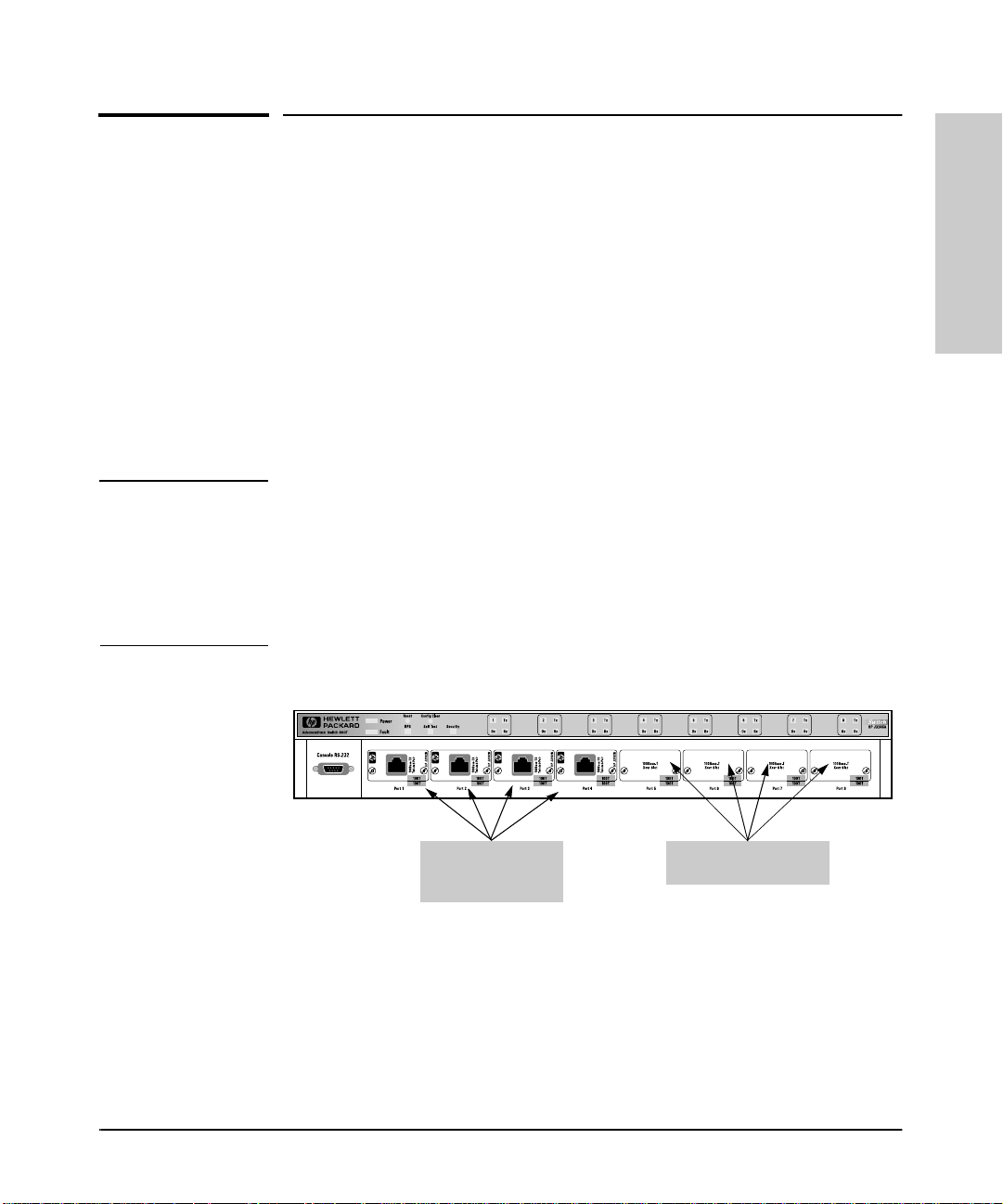
Example of the HP AdvanceStack Switch 800T with Four 100Base-TX Transceivers
installed
When powered-up in the factory default co n f igu r ation, the Switch 800Tautomatically operates as a multiport learning bridge with the following
configuration:
■ All ports are enabled and are members of a single broadcast domain
■ Spanning tree protocol (STP) disabled
The console interface provides the following capabilities for use when you
want to move beyond this basic level of operation:
■ Monitoring system performance and status
■ Customizing the system configuration for improved performance and
unique system requirements
■ Enabling network management (SNMP) access
■ Setting passwords to help protect system security
■ Downloading system software updates
■ Troubleshooting
iv
Page 9

Contents
Contents
1: Installation
Installa tion Summary . . . . . . . . . . . . . . . . . . . . . . . . . . . . . . . . . . . . . . . . . . 1-1
1. Install Add-In Transceivers (Optional) . . . . . . . . . . . . . . . . . . . . . . . 1-3
2. Verify the Switch’s O peration . . . . . . . . . . . . . . . . . . . . . . . . . . . . . . . 1-6
3. Mount the Switch . . . . . . . . . . . . . . . . . . . . . . . . . . . . . . . . . . . . . . . . . . 1-8
4. Connect a Power Supply . . . . . . . . . . . . . . . . . . . . . . . . . . . . . . . . . . . 1-16
5. Complete the Network Connections to the Switch . . . . . . . . . . 1-19
6. Connect a Console D evice (Optional) . . . . . . . . . . . . . . . . . . . . . . 1-21
Where To Go from Here . . . . . . . . . . . . . . . . . . . . . . . . . . . . . . . . . . . . . . 1-25
2: Using the Consol e Interface
Overview . . . . . . . . . . . . . . . . . . . . . . . . . . . . . . . . . . . . . . . . . . . . . . . . . . . . . 2- 1
Starting and Ending a Console S ession . . . . . . . . . . . . . . . . . . . . . . . . . 2-2
Main Menu Features . . . . . . . . . . . . . . . . . . . . . . . . . . . . . . . . . . . . . . . . . . 2- 4
Screen Structur e and Navigation . . . . . . . . . . . . . . . . . . . . . . . . . . . . . . . 2- 5
Using Password Secu ri ty . . . . . . . . . . . . . . . . . . . . . . . . . . . . . . . . . . . . . . . 2-7
Rebooting the Switch . . . . . . . . . . . . . . . . . . . . . . . . . . . . . . . . . . . . . . . . . 2-10
Resetting the Switch . . . . . . . . . . . . . . . . . . . . . . . . . . . . . . . . . . . . . . . . . 2-12
3: Configuring the Switch
Overview . . . . . . . . . . . . . . . . . . . . . . . . . . . . . . . . . . . . . . . . . . . . . . . . . . . . . 3-1
Configurable Features . . . . . . . . . . . . . . . . . . . . . . . . . . . . . . . . . . . . . . . . . 3- 3
System Features . . . . . . . . . . . . . . . . . . . . . . . . . . . . . . . . . . . . . . . . . . . . 3-5
Port Features . . . . . . . . . . . . . . . . . . . . . . . . . . . . . . . . . . . . . . . . . . . . . . . 3-6
IPX Service Features . . . . . . . . . . . . . . . . . . . . . . . . . . . . . . . . . . . . . . . . . 3- 7
Internet (IP) Service Features . . . . . . . . . . . . . . . . . . . . . . . . . . . . . . . . . 3-9
Virtual LAN (VLAN) Features . . . . . . . . . . . . . . . . . . . . . . . . . . . . . . . . 3-11
IP Multicast (IGMP) Service Features—Multimedia Traffic Control 3-12
v
Page 10

Contents
SNMP Communities Features . . . . . . . . . . . . . . . . . . . . . . . . . . . . . . . . 3-13
Trap Receivers F e at u res . . . . . . . . . . . . . . . . . . . . . . . . . . . . . . . . . . . . . 3-15
Serial Link Features . . . . . . . . . . . . . . . . . . . . . . . . . . . . . . . . . . . . . . . . 3-16
Console Features . . . . . . . . . . . . . . . . . . . . . . . . . . . . . . . . . . . . . . . . . . . 3-17
Network Monitoring Port Features . . . . . . . . . . . . . . . . . . . . . . . . . . . . 3-18
Spanning Tree Features . . . . . . . . . . . . . . . . . . . . . . . . . . . . . . . . . . . . . 3-21
Traffic/Security Filter Features . . . . . . . . . . . . . . . . . . . . . . . . . . . . . . . 3-22
Automatic Broadcast Control (ABC) Features—Layer 3 Switching 3-23
4: Monitoring and Analyzi ng Switch Operation from the
Console
Overview . . . . . . . . . . . . . . . . . . . . . . . . . . . . . . . . . . . . . . . . . . . . . . . . . . . . . 4-1
Status and C ounters Menu . . . . . . . . . . . . . . . . . . . . . . . . . . . . . . . . . . . . . 4-2
Switch Information . . . . . . . . . . . . . . . . . . . . . . . . . . . . . . . . . . . . . . . . . . 4-3
Port Status . . . . . . . . . . . . . . . . . . . . . . . . . . . . . . . . . . . . . . . . . . . . . . . . . 4-4
Port Counters . . . . . . . . . . . . . . . . . . . . . . . . . . . . . . . . . . . . . . . . . . . . . . . 4-5
Address Table . . . . . . . . . . . . . . . . . . . . . . . . . . . . . . . . . . . . . . . . . . . . . . 4- 7
Port Address Table . . . . . . . . . . . . . . . . . . . . . . . . . . . . . . . . . . . . . . . . . . 4-8
Spanning Tree (STP) Information . . . . . . . . . . . . . . . . . . . . . . . . . . . . . 4-10
IP Multicast (IGMP) Status . . . . . . . . . . . . . . . . . . . . . . . . . . . . . . . . . . 4-12
Automatic Broadcast Control (ABC) Information . . . . . . . . . . . . . . . 4-14
Event Log . . . . . . . . . . . . . . . . . . . . . . . . . . . . . . . . . . . . . . . . . . . . . . . . . . . . 4-15
5: Using SNMP To Monitor and Manage the Switch
SNMP Management . . . . . . . . . . . . . . . . . . . . . . . . . . . . . . . . . . . . . . . . . . . . 5-1
SNMP Co nfi guration P rocess . . . . . . . . . . . . . . . . . . . . . . . . . . . . . . . . . . 5- 3
6: Using the Advanc ed Commands
Overview . . . . . . . . . . . . . . . . . . . . . . . . . . . . . . . . . . . . . . . . . . . . . . . . . . . . . 6- 1
Commands . . . . . . . . . . . . . . . . . . . . . . . . . . . . . . . . . . . . . . . . . . . . . . . . . . . . 6- 4
vi
Page 11

Contents
7: Advanced Concepts
Overview . . . . . . . . . . . . . . . . . . . . . . . . . . . . . . . . . . . . . . . . . . . . . . . . . . . . . 7- 1
Spanning Tree Protoc ol (STP) . . . . . . . . . . . . . . . . . . . . . . . . . . . . . . . . . 7-2
Port Trunking . . . . . . . . . . . . . . . . . . . . . . . . . . . . . . . . . . . . . . . . . . . . . . . . . 7-5
Filters and Security . . . . . . . . . . . . . . . . . . . . . . . . . . . . . . . . . . . . . . . . . . . 7-8
Virtual LANs (VLANs) . . . . . . . . . . . . . . . . . . . . . . . . . . . . . . . . . . . . . . . . 7-14
Effect of VLANs on Other Switch Features . . . . . . . . . . . . . . . . . . . . . 7-15
How To Configure a VLAN . . . . . . . . . . . . . . . . . . . . . . . . . . . . . . . . . . . 7-17
VLAN Restrictions . . . . . . . . . . . . . . . . . . . . . . . . . . . . . . . . . . . . . . . . . . 7-21
IP Multi cast (IG MP) . . . . . . . . . . . . . . . . . . . . . . . . . . . . . . . . . . . . . . . . . 7-23
How IGMP Operates . . . . . . . . . . . . . . . . . . . . . . . . . . . . . . . . . . . . . . . . 7-23
How To Configure IGMP . . . . . . . . . . . . . . . . . . . . . . . . . . . . . . . . . . . . 7-26
Automatic Broadcast Control (ABC) . . . . . . . . . . . . . . . . . . . . . . . . . . 7-30
How ABC Operates . . . . . . . . . . . . . . . . . . . . . . . . . . . . . . . . . . . . . . . . . 7-30
How To Configure ABC . . . . . . . . . . . . . . . . . . . . . . . . . . . . . . . . . . . . . 7-32
8: File Transfer s
Overview . . . . . . . . . . . . . . . . . . . . . . . . . . . . . . . . . . . . . . . . . . . . . . . . . . . . . 8- 1
Downloading an Operating System . . . . . . . . . . . . . . . . . . . . . . . . . . . . . 8- 2
Using TFTP To Download the OS File . . . . . . . . . . . . . . . . . . . . . . . . . . 8-3
Switch-to-Switch Download . . . . . . . . . . . . . . . . . . . . . . . . . . . . . . . . . . 8-5
Troubleshooting TFTP Downloads . . . . . . . . . . . . . . . . . . . . . . . . . . . . . 8-6
Transferring Switch 800T Configurations . . . . . . . . . . . . . . . . . . . . . . . 8-8
9: Troub les hooting
Troubleshooting Approaches . . . . . . . . . . . . . . . . . . . . . . . . . . . . . . . . . . . 9- 1
Diagnosi ng with the LE Ds . . . . . . . . . . . . . . . . . . . . . . . . . . . . . . . . . . . . . 9-2
Installation Problems . . . . . . . . . . . . . . . . . . . . . . . . . . . . . . . . . . . . . . . . . 9-5
Incorrect Hardware Installation . . . . . . . . . . . . . . . . . . . . . . . . . . . . . . . 9-5
Console RS-232 Problems . . . . . . . . . . . . . . . . . . . . . . . . . . . . . . . . . . . . 9- 5
Cabling Problems . . . . . . . . . . . . . . . . . . . . . . . . . . . . . . . . . . . . . . . . . . . 9- 6
Unusual Network Activity . . . . . . . . . . . . . . . . . . . . . . . . . . . . . . . . . . . . . 9-7
vii
Page 12

Contents
Diagnostic Tests . . . . . . . . . . . . . . . . . . . . . . . . . . . . . . . . . . . . . . . . . . . . . . 9-7
Testing Twis t e d -Pair Cabling . . . . . . . . . . . . . . . . . . . . . . . . . . . . . . . . . . 9- 8
Testing End-to-End Network Communications . . . . . . . . . . . . . . . . . . 9-8
Customer Support Services . . . . . . . . . . . . . . . . . . . . . . . . . . . . . . . . . . . . 9-8
A: Cables and Connectors
Recommended Cables . . . . . . . . . . . . . . . . . . . . . . . . . . . . . . . . . . . . . . . . A-2
Twisted-Pair Cable/Connector Pin-Outs . . . . . . . . . . . . . . . . . . . . . . . A-3
Twisted-Pair Cable Pin Assignments . . . . . . . . . . . . . . . . . . . . . . . . . . A-5
RS-232 Connector and Cable Pin-Outs . . . . . . . . . . . . . . . . . . . . . . . . . A-6
RS-232-C “Null Modem” Cable . . . . . . . . . . . . . . . . . . . . . . . . . . . . . . . . A-7
Minimum Cable Pin-out for Direct Console Connection . . . . . . . . . . A- 7
RS-232 Modem Cable . . . . . . . . . . . . . . . . . . . . . . . . . . . . . . . . . . . . . . . A-8
B: Specifications
Physical . . . . . . . . . . . . . . . . . . . . . . . . . . . . . . . . . . . . . . . . . . . . . . . . . . . B-1
Electrical . . . . . . . . . . . . . . . . . . . . . . . . . . . . . . . . . . . . . . . . . . . . . . . . . B-1
Environmental . . . . . . . . . . . . . . . . . . . . . . . . . . . . . . . . . . . . . . . . . . . . . B-1
Connectors . . . . . . . . . . . . . . . . . . . . . . . . . . . . . . . . . . . . . . . . . . . . . . . . B- 2
Electromagnetic . . . . . . . . . . . . . . . . . . . . . . . . . . . . . . . . . . . . . . . . . . . B- 2
Safety . . . . . . . . . . . . . . . . . . . . . . . . . . . . . . . . . . . . . . . . . . . . . . . . . . . . B-2
viii
C: Sample Console Configurations
Windows 3.1 Terminal Application . . . . . . . . . . . . . . . . . . . . . . . . . . . . C- 1
Procomm Plus V2.01 . . . . . . . . . . . . . . . . . . . . . . . . . . . . . . . . . . . . . . . . . . C-2
Other Terminal Emulators . . . . . . . . . . . . . . . . . . . . . . . . . . . . . . . . . . . . C-3
D: Switch Reference
Front of Switch . . . . . . . . . . . . . . . . . . . . . . . . . . . . . . . . . . . . . . . . . . . . . . D-1
Back of the Switch . . . . . . . . . . . . . . . . . . . . . . . . . . . . . . . . . . . . . . . . . . . D-1
Page 13

Contents
E: BOOTP Operat ion
Overview . . . . . . . . . . . . . . . . . . . . . . . . . . . . . . . . . . . . . . . . . . . . . . . . . . . . E- 1
The Bootp Process . . . . . . . . . . . . . . . . . . . . . . . . . . . . . . . . . . . . . . . . . . . E-1
Bootp Database Record Entries . . . . . . . . . . . . . . . . . . . . . . . . . . . . . . . E- 2
Configuring Bootp . . . . . . . . . . . . . . . . . . . . . . . . . . . . . . . . . . . . . . . . . . . . E- 3
F: MAC Address Management
Overview . . . . . . . . . . . . . . . . . . . . . . . . . . . . . . . . . . . . . . . . . . . . . . . . . . . . . F-1
Switch (Default) MAC Address . . . . . . . . . . . . . . . . . . . . . . . . . . . . . . . . F-2
VLAN MAC Addresses . . . . . . . . . . . . . . . . . . . . . . . . . . . . . . . . . . . . . . . . . F-3
MAC Addresses (for Spanning Tree Operation) . . . . . . . . . . . . . . . . . F-4
Safety and Regulatory Statement s
Index
ix
Page 14

Page 15

Installation
1
Installation
Installation Summary
This chapter describes the installation procedures for the HP J3245A
AdvanceStack Switch 800T (h er eafter referred to as the Switch 800T).
The following is a summary of those procedures:
1. Site Preparation. Ensure that the cabling infrastructure meets the
network specifications for your intended use of the Switch 800T.
• For 100Base-TX transc eivers used in the Swi tch 800T, us e categor y 5,
four-pair, 100 oh m UTP (unshielded twisted-pair) cabl es. Cable
lengths can be up to 100 meters. For a connection to an end node, use
straight-through cable. For a connection to a hub or a switch, use a
crossover cable.
• For 100Base-FX transcei vers used in the Switch 800T, use fiber
optical cable s that:
– Are fitted with type SC connectors
– Conform to ISO/IEC 793-2 type B1 and ITU-T G.652 standa rds
Caution Ensure that the power source circuits are adequate and properly
grounded. That is, ensure that any Switch 800T installation , together with
any other devices, does not overload the power circuits, wiring, and overcurrent protection. To determine the possibility of overloading the supply
circuits, add together the ampere ratings from the nameplates of all
devices installed o n the same circuits and compare the total with the
rating limits for the supply circuits. For additional information, refer to
appendix B, “Specifications”.
1-1
Page 16

Installation
Installation
Installation Summary
2. Install transceivers (optional). The Swi t ch 800T is shipped wi th fo u r
HP J3192B AdvanceStack 10 0Base-TX Twis ted-Pair Transceive r Modules
(referred to in this manual as “trans ceiv ers”) already insta lle d.
Caution Because the Switch 800T can be damaged by installing or removing a
transceiver while powered-up, the ONLY time to install additional
transceivers is before powering up the switch or with the power
disconnected during scheduled down times.
The J3192A
Always use the “B” version (J 3192B
twisted-pair transceiver is not supported in the Switch 800T.
) or any later J3192 transceiver(s).
3. Verify the switch’s operation. This is a simple process of applying
power to the Switc h 800T and ensuring that the LEDs on the switch’s fr ont
panel respond properly.
4. Mount the switch in a rack, o n a wall, or on a tabletop.
Hewlett-Packard sells 19-inch free-standing eq ui p ment racks. To order a
rack, contact your HP-authorized LAN dealer.
5. (Optional) Connect the J2962A HP AdvanceStack Redundant
Power Supply (RPS) instead of using the switch’s own power
supply. This optional power supply can be used instead of the switch’s
main power supply to provide both primary and backup (redunda nt)
power to keep the switch operating in the event of a failure in either a
power circuit or a power supply unit.
6. Connect the Switch 800T to a network and co nnect computers and/
or other devices to the switch’s ports.
7. Configure the Switch 800T. The Switch 800T, in its factory default
configuration, operates as a multiport transparent bridge. You will ne ed
to use the console interface utility to configure the switch for additional
functionality. Initially, this requires one of the following:
• A PC with a terminal emulato r conn ected to the Consol e RS- 232 por t
on the switch either directl y or via a modem
• An actual terminal directly connected to the Consol e RS-232 port on
the switch
1-2
(For examples of terminal emulator configurations, refer to appendix C,
“Sample Console Configurations”. )
After configuring a minimal IP or IPX configuration through one of the
above options, you can also access the console interface via Telnet o r use
a network management tool, such as Hewlett-Pack ar d ’s AdvanceStack
Assistant, for some configuration and monitoring functions.
Page 17
1. Inst all Add-In Transceivers (O ptional)
Installation
1. Install Add-In Transceivers (Optional)
The Switch 800T is shipped with four HP J3192B AdvanceStack 100Base-TX
Twisted-Pair Transceiver Modules already installed. (The switch does not
support use of the “A” version—HP J3192A—o f t his tr an sceiver.) Additional
twisted-pair (UTP) or fiber transceivers must be purchased separately. (You
need a minimum of one transceiver inst alled to connect the switch to your
network, and one additional trans ceiver installed for each connectio n to a
server, hub, switch, or other device.) The Switch 800T is designed to operate
with either of the following two tran sceivers:
■ HP J3192B AdvanceStack 100Base-TX Twisted-Pair Transceiver Module
■ HP J3193B AdvanceStack 100Base-FX Fiber-Optic Transceiver Module
Caution To avoid damage to circuitry in the Switch 800T and transceivers,
always have the power to the Switch 800T turned off while a transceiver is being installed or removed.
For proper cooling and for reduction of electromagnetic emissions, ensure
that a slot cover (provided with your Switch 800T) is installed on any unused
transceiver slot.
Installation
Factory-Installed
100Base -T X (UTP)
Transceivers
Slot Covers on Unuse d
Trans ceiver Slo t s
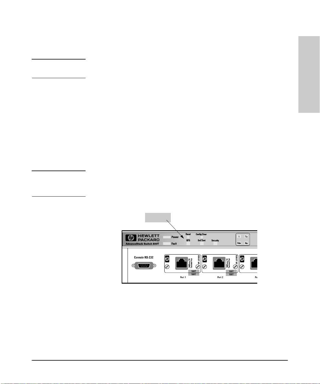
Figure 1-1. Switch 800T with Factory-Installed HP J3192B 100Base-TX (UTP)
Transceivers
1-3
Page 18

Installation
Installation
1. Install Add-In Transceivers (Optional)
It may be more convenient to install additional trans ceivers before install ing
the Switch 800T into a rack or other location. Inspect your installa tion site and
determine whether the switch’s module slots will be accessible.
For a description of cur r ently available transcei vers, contact your
HP-authorized LA N deal er or check Hewlett-Packard’s World Wide Web site
listed on the card at the front of this manual.
To Install a Transceiver into the Switch 800T: This procedure describes the general installation of a transce iver. For information on the specific transceiver you are installing, plus specific connection and troubleshooting information, refer to the HP 100Base-T Transceiver Mod ules Installation Guide you received with the transceiver.
1. Unplug the Switch 800T from the AC power source.
Caution To avoid damage to circuitry in the Switch 800T and transceivers,
always have the power to the Switch 800T turned off while a
transceiver is being installed or removed.
2. Use a flat-bladed or Torx T-10 screwdriver to unscrew the two retaining
screws from the cover plate on the slot in which you want to install the
transceiver . For example, to i nstall an HP J3192B Advan ceStack 100Bas eTX Twisted-Pair Transceiver Module for port 5:
1-4
Loosen These Scr ew s
Figure 1-2. Remove the Cover Plate from the Transceiver Slot
Retain the cover plate for future use. If you remove a transceiver in the
future without replacing it, cover the unused slot with one of these cover
plates.
Page 19
1. Inst all Add-In Transceivers (O ptional)
Installation
Caution For proper cooling and reduction of electromagnetic emissions, ensure
that the slot cove rs (provid ed with your Switch 800T) are installed o n any
unused slots.
3. While constantly touching a metal part of the Switch 800T to discharge
any static electric difference between your body and the switch, carefully
remove the tra nsceiver from i ts protectiv e anti-st atic packagi ng. Hold the
transceiver b y its edges, ta ki n g care not to touch an y of its metal connectors.
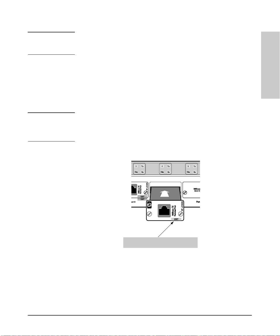
4. Slide the transceiver firmly into the open slot as far as it will go. The
transceiver’s faceplate should touch the face of the device.
Note Ensure that the transceiver you are installing has a blue color bar with the
word “100T” printed on it ([ 100T ]). (See figure 1-3, below.) Any transceiver
that does not have this bar will not operate with the Switch 800T and will cause
a fault condition.
Installation
Blue “100T” Color Bar Indicating a
Correct Transceiver for the Switch 800T
Figure 1-3. Slide the Transceiver into the Slot
5. Tighten the retainin g screw s on the tran sceiver until they are snug. Be
careful that you do not overtighten the screws.
6. To install another trans ceiver, return to step 2. Otherwise, go on to the
next procedure (page 1-6) .
1-5
Page 20

Installation
2. Verify the Swi tch’s Operation
2. Verif y the Switch’s Operation
This process verifies that the Switch 800T is operating properly.
Installation
Verify the Switch Hardware
1. Connect the supplied power cord to the switch’s power receptacle.
Power Rec eptac le on
the Back of the Switch
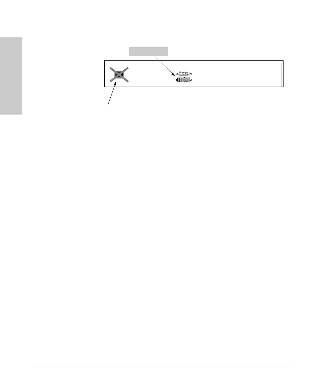
Figure 1-4. Back Panel of the Switch 800T
2. Plug the power cord into a properly grounded electrical outlet.
Note The Switch 800T does not have a power switch. It is powered on when the
switch’s power cord is connec ted to the switch and to a power source.
If your installation requires a different power cord than the one supplied with
the switch, be sure to use a power cord displaying the mark of the safety
agency that defines the regulations for power cords in your country. The mark
is your assurance that the power cord can be used safely with the switch.
1-6
3. Check the LEDs on the switch’s front panel.
Page 21

2. Verify the Switch’s Operation
Installation
Power LED
Fault LED
RPS LED
Self-test LED
Security LED
Figure 1-5. The Switch 800T System LEDs
When the switch i s powered on, it perfor ms a self- diagno stic te st. Dur ing
the test, the following occurs:
• All LEDs turn on momentarily.
• The Power LED remains on.
• The RPS LED turns on if an RPS is connected and supplying power.
• The Self-test and Fault LEDs remain on for less than one minute.
When the self-test completes successfully, the following events occur:
• The power LED and, if an RPS is connected, the RPS LED, remain on.
• The self-test and Fault LEDs turn off.
Installation
Note If any Fault LED is flashing, the Switch 800T has encountered a problem. Refer
to chapter 9, “Troubleshooting”.
4. After the swit ch has p assed it s self- tes t, turn t o “3. M ount t he Switch” , on
the next page.
Note If the switch’s permanent location makes it difficult to access the Console
RS-232 port from a terminal or PC running a terminal emulator, you may want
to temporarily connect a terminal device now and configure the switch
minimally for Telnet acce ss. If you want to do this, refer to “ Connect a Console
Device” on page 1-21 before cont in u ing here.
1-7
Page 22

Installation
Installation
3. Mount the Switch
3. Mount the Switch
A Switch 800T can be mounted in two ways:
■ In a rack or cabinet
■ On a table
■ On a wall
The hardware for mounting the switch is included in the accessory kit
(5063-8544) packed with the switch.
Hewlett-Packard sells 19-inch free-standing equ ipment racks. For more
information, contact your HP authorized LAN dealer.
Mounting
Precautions
Before mounting the switch, read and follow these mounting precautions:
■ Plan the switch’s location and orientation relative to other devices and
equipment. Also consider the cabling that will be attached to the switch
and ports that will be used. In the front of the switch, leave 3 inches
(7.6 cm) of space for twisted-pai r cables. In the back of the switch, leave
1-1/2 inches (3.8cm) of space for the power cord.
■ Ensure that any installation of a Switch 800T, together with any other
devices, does not overload the power circuits, wiring, and over-current
protection. To determine the possibility of overloading the supply circuits,
add together the ampere ratings from the nameplates of all devices
installed on the same circuits and compare the total with the rating limits
for the supply circuits.
■ Make sure that the power source circuits are properly grounded, then use
the supplied power cord to connect the Switch 800T to the circuit. Refer
to the Safety and Regulatory Statements that follow the appendixes at the
back of this manual.
■ Do not install the Switch 800T in an environme n t where the operating
ambient temperature mi gh t exc eed 55°C (131°F).
■ For proper cooling, make sure the air flow around the sides and back of
the switch is not restricte d.
■ If an HP J2962A AdvanceStack Swit ch 800T Redundant Power Supply is
installed, make sure the air flow around the fan area of the RPS is not
restricted.
1-8
Page 23

Rack or Cabinet Mounti ng
3. Mount the Switch
Installation
Warning The rack or cabinet should be adequately secured to prevent it from
becoming unstable and/or falling over.
Install the Switch 800T only on a tabletop or an equipment rack or
cabinet designed for this product. The Switch 800T weighs 9.5 lbs (4.3
kilos) with four transceivers installed. Devices installed in a rack or
cabinet should be as low as possible, with the heaviest device at the
bottom and progressively lighter devices installed above.
1. If you will be using the optional HP J2962A HP AdvanceSta ck Redundant
Power Supply (RPS) with the Switch 800T, refer to the Installation and
Reference Guide s hipped wi th the RPS for ins tructions on how to i nstall
it in a position from which it can be used with the Switch 800T.
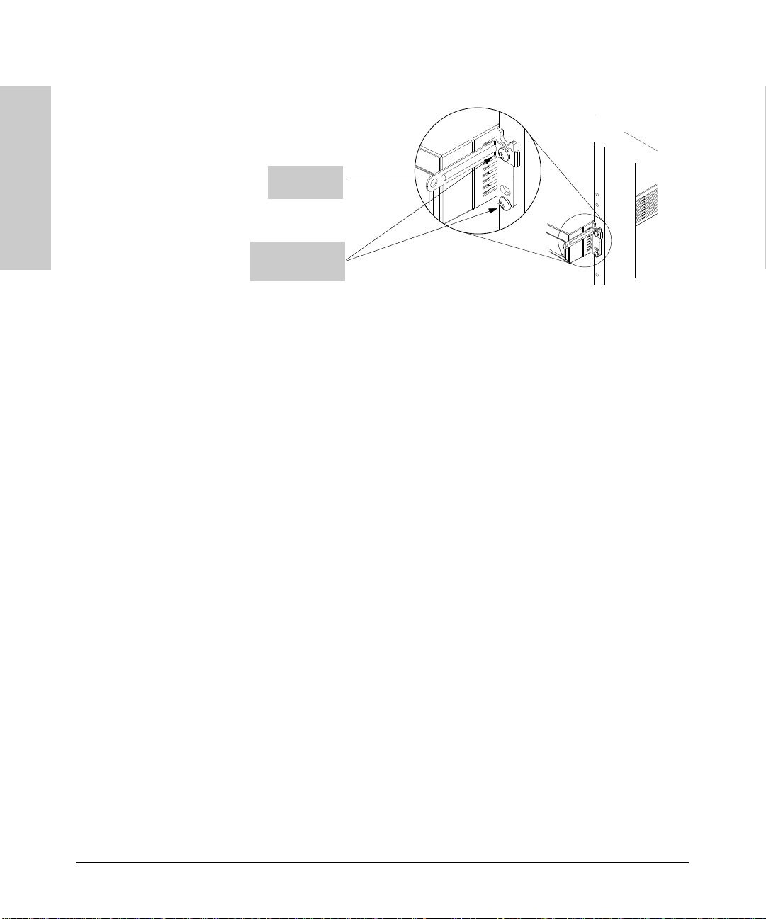
2. As shown below, partially install one of the 5/8-inch number 12-24 screws
in each rack upright. Install the screw in the upper hole of a close pair.
(Some cabinets r equ ire number 10-32 screws instead, which are not
included in the accessory kit.)
Caution Make sure you have screws that fit your cabinet or rack before mounting the
switch.
Insert a screw into the
top hole of a close pair
(0.5-i nch)—like one of
these—on e in each of
the rack uprights.
Installation
One upright of an EIA
19-inch telco rack
Figure 1-6. Installing the Mounting Screws
1-9
Page 24

Installation
Installation
3. Mount the Switch
3. Using a Phillips cross-head screwdriver, att ach the L-s h ap ed mounting
brackets to each side of the switch with four 10-mm M4 screws (included
in the accessory kit).
Align Top of
Bracket with
Top of Switch
10-mm M4
Screws
1-10
Figure 1-7. Attach the Mounting Brackets
4. Place the switch in t he ra ck and l ower it so the notches in the bottom of
the bracket slide ont o the screw s you in stalled in step 1. Tighten these
screws—be careful not to overtighten. (Refer to figures 1-8 and 1-10.)
Page 25

Figure 1-8. Position the S witch for Rack Mounting
3. Mount the Switch
Installation
Installation
Figure 1-9. Seat the Switch in the Rack
5. Install the other two 5/8-inch 12-24 screws into the upper hol e in each
bracket. Include the cable-tie bracket on the side on which you want to
lead your network cables. (For example, see below.) Tighten these
screws—be careful not to overtighten.
1-11
Page 26
Installation
Installation
3. Mount the Switch
Cable-Tie
Brack et
5/8-inch #12- 24
screws
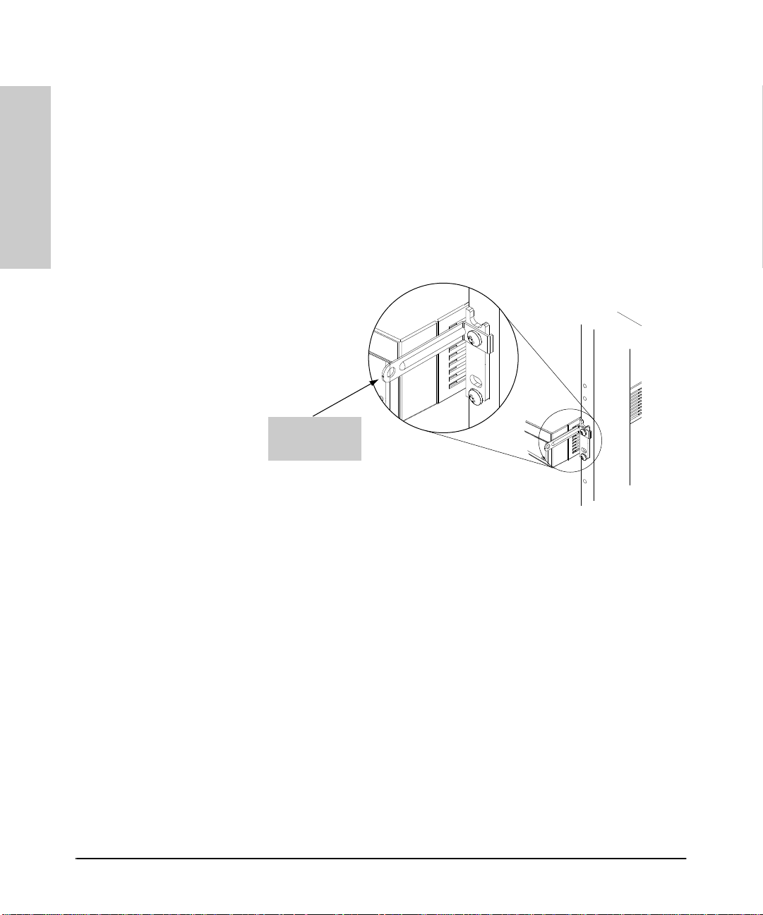
Figure 1-10. Install the Switch in the Rack
1-12
Page 27
3. Mount the Switch
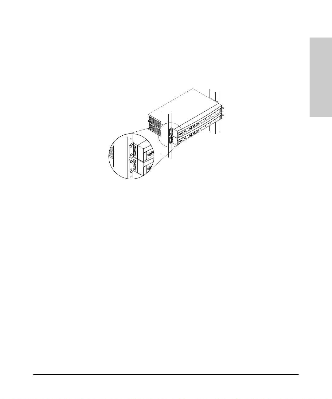
Notice that for the first AdvanceStack device mounted in a rack, the
bottom notch and the top hole in the bracket are used. For the next
AdvanceStack device above, the bottom hole and the top notch are used.
(Refer to figure 1-11, below.) Continue to alternate “notch and hole, hole
and notch” for all AdvanceStack devices to be consecutively installed.
Figure 1-11. Correct Rack Mounting for Multiple AdvanceStack Devices
Installation
Installation
1-13
Page 28

Installation
Installation
3. Mount the Switch
Mounting the Switch on a Wall
Caution The Switch 800T should be mounted only to a wall or wood surface that is
constructed of a minimum of 1/2-inch plywood or its equivalent.
1. Using a Phillips (cross-head) screwdriver, attach the mounting brackets
to the switch in one of the positions shown in the following two illustrations. Use the 10-mm M4 screws included in the mounting kit.
2. Attach the switch to the wall or wood surface with 5/8-inch number 12
wood screws (not included).
Bracket Mounting
Position on a Wall
for Connectors
Facing Upward
10-mm M4
screws
1-14
Bracket
Mounting
Position on a Wall
for Connectors
Facing Outward
10-mm M4
screws
Figure 1-12. Bracket Positions for Wall-Mount Options
Plug the powe r
cord into t he
switch’s power
receptacle
before mounting
the switch. There
may not be
enough room to
do so after the
switch is
mounted.
Page 29

3. Mount the Switch
Installation
Table Mounting
Place the switch on a t ab le o r other h orizontal surface. (N o sp ecial tools are
necessary.)
Be certain to pi ck a sturdy table in an unclutter ed area. You may want to secure
the switch’s cables to the leg of the table to help prevent people from trippi ng
over them.
Caution Make sure the air flow around the sides and back of the switch is not restricted.
Also, if an HP J2962A AdvanceStack Redundant Power Supply is installed,
make sure the air flow around the fan area of the RPS is not restricted.
Route the power cord(s) and data cab les so that t hey will not create a tripping
hazard for people walking in the area of the switch installation.
Installation
1-15
Page 30

Installation
Installation
4. Connect a Power S upply
4. Connect a Power Supply
The Switch 800T does not have a power switch. It is powered-on when the
power cord is pl ugged i n. Th e swit ch’s power s upply au tomatica ll y adjus ts to
any AC power source between 100-127 volts and 200-240 volts. There are no
voltage range set t in gs to configure.
You can use one of the following to provide power to the Swit ch 800T:
■ The power cord provided with the Switch 800T.
OR
■ The optional HP J2962A AdvanceStack Redundant Power Supply (RPS).
To Use the Power Cord Provided with the Switch 800T:
Caution If you use a power c or d that plugs into the power cord receptacle
(figure 1-13), do not use th e opt i onal redu n dant pow er su pp l y ( RPS).
If your installation requ ires a different power cord than the one
supplied with the switch, be sure to use a power cord displaying the
mark of the safety agency that defines the regulations for power cords
in your country. The mar k i s your assurance that the power cord can
be used safely with the switch.
1. Ensure that the switch is properly mounted. (Refer to “3. Mount the
Switch” on page 1-8.)
2. Plug the power c ord into the switch’s pow er co rd receptacle and into an
AC power source.
Power Cord Receptacle
on the Back of the Switch
Figure 1-13. Plugging in the Power Cord
1-16
Page 31
4. Connect a Power Supply
Installation
To Use the (Optional) HP J2962A AdvanceStack Redundant
Power Supply (RPS):
Caution Remove the power cord from the Switch 800T before connecting the
(optional) redundant power supply (RPS).
You can use the opt ional HP J2962 A Adva nceS tack Red undant Power S upply
(RPS) instead of the Switch 800T’s built-in power supply. This can help ensure
continuous switch operation in the event of a power failure on an individual
power supply circuit. It also eliminates reliance on a single d evice power
supply. To connect the RPS to the Switch 800T, it is necessary to first turn
off powe r to t he switch by removing the switch’s own pow e r co rd. Thus, if
you are using the RPS, Hewlett-Packard recommends that you connect the
RPS to the Sw itch 800T before connecting the switch to your network. Otherwise, you must schedule downtime to connect the RPS. When the RPS is
connected to a Switch 800T and power is applied to the RPS, the RPS LED on
the Switch 800T’s front panel is lit.
Note For importan t info rmati on on h ow to i nstal l and connect the (optio nal) HP
J2962A AdvanceStack Switch 800T Redundant Power Supply (RPS) for use
with the Switch 800T, refer to the documentation provided with the RPS.
Installation
RPS LED
Figure 1-14. RPS LED on the Switch 800T’s Front Panel
1-17
Page 32
Installation
Installation
4. Connect a Power S upply
RPS Connector
Note: Do Not Use the Po w er Cord Receptacle If You Plan To Use the RPS with th e Switch.
Figure 1-15. Location of the RPS Connector
1-18
Page 33
5. Complete the Network Connections to the Switch
Installation
5. Complete the Network Connections
to the Switch
Connect the switch to the power source. With the switch mounted, you are
now ready to connect it to your network. Typical switch connections are:
■ Switch-to-netwo rked devices (i.e. servers, an d pr in ters).
■ Switch-to-hub
■ Switch-to-switch
■ Switch-to-router
Note Refer to the HP AdvanceStack Switch 800T Connectiv ity Quick Reference that
is shipped with the Switch 800T for exampl es of Switch 800T connections to
other devices.
For other network design guidelines, refer to An Introduction to Ethernet
LAN Switches and Designing Switched Networks, both of which are included
on the CD shipped with the Switch 800T. For physical topology guidelines,
refer to Designing HP AdvanceStack Workgroup Networks, available from
HP authorized LAN deal ers and also on the CD shipp ed with your Switch 800T.
Network connections to the Switch 800T are thr o ugh por ts on the optio n al
transceivers installed in the switch.
Installation
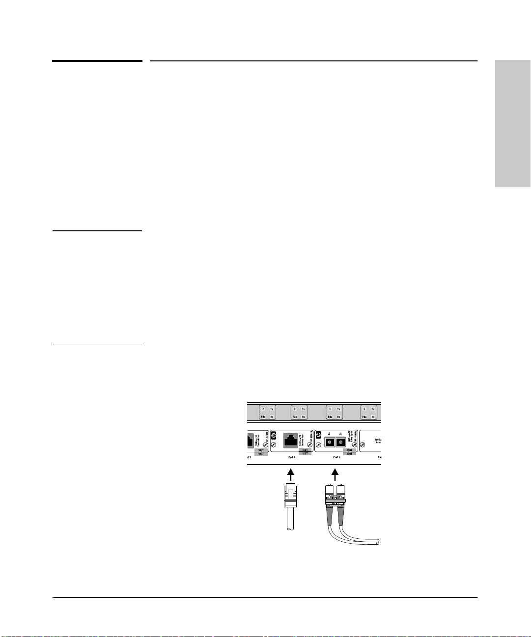
Figure 1-16. Network Connections
1-19
Page 34
Installation
5. Complete the Network Connect ions to the Switch
For connections to these po rts, see the documentati on you received with the
specific transceiver, and to the Connectivity Quick Reference mentioned i n
the preceding note.
Cable Management.
Installation
The mounting brackets designed for the Switch 800T provide help for the
problem of managing your network cables. Each bracket has a series of holes
for attaching a cable tie to bundle network cables away from the switch.
Hole for Cable
Tie to Bundl e
Network Ca bles
Figure 1-17. Cable Management
1-20
Page 35

6. Connect a Console Device (Optional)
Installation
6. Connect a Console Device (Optio nal)
The Switch 800T con sole interfac e enable s you to use a PC or a te rminal to do
the following:
■ Control password security
■ Monitor switch and port statistics
■ Modify the switch’s configuration, or provide a minimal configuration for
Telnet or network manageme nt product s (used for in-band access to the
switch) such as Hewlett-Packard’s AdvanceStack Assistant (ASA)
■ Use the switch’s event log and command line to help in troubleshooting
■ Download new version of switch software (OS)
Note The Switch 800T is shipped with a factory default configur ation that enables
operation as a multiport transparent bridge (switch) when installed in a
network. For this operation, connecting a console device is unnecessary.
However, for some of the other uses listed above, you will need to have
console access.
You can use either of the following methods for console access:
■ Console RS-232 using either a direct or modem connection to a PC
terminal emulator program, or a dir ect co n ne ctio n to an actual termin al
■ In-Band using Telnet from a network management workstation. (To
enable Telnet—or network management access—it is necessary to first
use a di rect-connect or mode m-connect cons ole devic e to configure an IP
address and subnet mask for the switch.)
Installation
The Switch 800T can simultaneously support one console session via the
Console RS-232 port and one console session via Telnet.
1-21
Page 36

Installation
6. Connect a Cons ole Device (Optio nal)
Direct Console Management, Using A Serial Cable and a
Terminal or PC Terminal Emulator
You can use either a PC emulating an ASCII terminal (such as the terminal
application included with Microsoft Windows 3.1, Windows 95, or Windows
NT) or an ASCII terminal.
Installation
To directly connect a PC or terminal to a Switc h 800 T, fol low these steps:
1. Connect the PC or terminal to the switch’s Console RS-232 port usin g an
RS-232-C console cable (included). (If you n eed information on pin-outs
and recommended cables, see appendix A, “Cables and Connectors”)
Console RS- 2 32 Port
1-22
Figure 1-18. Connecting a PC or Termina l to the Console RS-232 Port
2. Turn on the terminal or PC’s power (and, if using a PC, start th e PC
terminal emulation program). For recommended parameter settings, refer
to appendix C, “Sample Console Configurations”.
Page 37
3. When you see this message:
Waiting for speed sense. Press enter to continue.
6. Connect a Console Device (Optional)
Installation
Press [Enter]. You will then see the Switch 800T’s Main Menu.
Note If the terminal emulator you are using is not set to 9600 Bps, you will see
a series of meaning less char acte rs. Press [Enter] to synchronize the switch
serial port speed with the terminal spe ed. The switch ’s serial port can use
one of severa l sp eeds be tween 300 Bps a nd 38400 Bps. In m ost cases , th e
switch’s Serial Link Baud Rate should be left at the (default) Speed
Sense setting. At this s etting , i t wil l au tomatical ly s ense ter min al speed s
in the above-mentioned range.
Installation
Figure 1-19. The Main Menu
4. If you want to contin ue with direct console ma nagement at this time, refer
to chapter 2, “Using the Console Interface”.
1-23
Page 38

Installation
6. Connect a Cons ole Device (Optio nal)
Remote Console Management Using a Modem and a Terminal
or PC Terminal Emulator
Note For remote console management use a full- duplex , asynch ronous (chara cter-
mode) modem.
Installation
1. At the Switch 800T site:
a. Connect the modem to the Switch 800T’s console port using an
RS-232-C modem cable. ( For pin-outs and recommended cables r efer
to appendix A, “Cables and Connectors”.)
b. If necessary, configure the modem to operate with the current con-
figuration of the Switch 800T . ( The modem’s default configuration
may be sufficien t .)
2. At the remote site, connect the termi n al ( or PC emulating a terminal) to
a modem using a modem cable. Make sure the terminal and modems are
functioning properly, then use the modem instructions to establish the
link between the terminal’ s modem and the Switch 800T ’s modem.
3. Refer to “Starting and Ending a Console Session” on page 2-2.
“Straight-Through
Modem Cable
RJ-11 Telephone
Cable
Switch 800T
External “Remote” Modem
1-24
“Straight-Through” Modem
Teleph one
Company
or Telco
RJ-11 Tel eph one
Cable
External “ Local ” M ode m. (Y ou can
also use an i nternal modem.)
Figure 1-20. Example of Remote Access via a Modem
PC Runni ng a
Terminal
Program
Page 39

Where To Go from Her e
Installation
Where To Go from Here
Chapter Topics
2 and 3 To use the cons ole and to configur e sw itch features
4 To monitor and analyze switch operation f rom the console
5 To prepare t he sw itch for SNMP management and to l earn
which MIBs are supported by the switch
6 To use the “Advanced Commands” functions
7 To find further information on the following features and to
configure them:
• Spanning Tr ee Protocol
• Port Trunking
• Filters and Security
• Virtual LANs
• Internet Group Management Protocol (IGMP)
• Automati c Broadcast Control (ABC)
8 To download a new operating syst em or transfer a switch
configuration
9 Troubleshooting information
Installation
Appendix Topic
A
B
C
D
E
F
Cable and conn ector informat ion
Switch specifications
Sample console configurations
LED reference
Bootp inform ation
MAC address management
Safety and Regulatory infor m ation
1-25
Page 40

Page 41

Using the Console Interface
Overview
This chapter descri b es the fo llowing features:
■ Starting and ending a console session (page 2-2)
■ The Main Menu (page 2-4)
■ Screen structure and nav igation (page 2-5)
■ Using password security (page 2-7)
■ Rebooting the switch (page 2-10)
■ Resetting the switch (page 2-12)
About the Console Inter face. The console in terface enab les you to reco nfigure the switch and to monitor the switch status and performance. It consists of a series of management screens accessed through a menu-driven screen structure that begins at the Main Menu, and is organized as described in this section.
2
Using the Console Interface
The Switch 800T offers two methods of access to the console interface:
■ Console RS-232 (ou t -o f-band) access:
• Directly connected to the Console RS-232 port, using a serial cable
and a PC running a terminal emulato r or an actual terminal
• Remotely connected to the Console RS-232 port, using modems and
a PC running a terminal emulator or an actual terminal
Refer to chapter 1, “Installation”, for information on making RS-232
hardware connections.
■ In-Band access using Telnet from a PC or UNIX station on the network.
This method requires that you first configure an IP address and subnet
mask by using either out-of-band console access or Bootp. The Switch
800T allows one outbound and one inbound Telnet session to be running
simultaneously.
Console access can be lim ited b y setting Manager-level and Operator -level
passwords.
2-1
Page 42

Using the Console Interface
Using the Console Interface
Starting and Ending a Console Session
Starting and Ending a Console Session
Note This manual assumes that either a termina l d evice is already configured an d
connected to your Switch 800T (as described in chapter 1, “Installati o n”) o r
that you have already enabled Telnet access to the switch. ( To enable Telnet
access, refer to “Cons ol e Features” on page 3-17.)
How To Start a Console Session:
1. Start your PC terminal emulator, terminal, or Telnet session on a remote
terminal device.
2. Do one of the following:
• If you are using Telnet, go to the next step.
• If you are using a PC terminal emulator or a terminal, you should then
see the following prom pt:
Waiting for speed sense. Press <enter> to continue.
Note: If the console displays a series of random and/or unread-
able characters instead of the above prompt, the Baud Rate
setting for the terminal may be different from that of the console
interface. The switch’s autosensing feature remedies this prob-
lem when yo u press a key.
2-2
Press [Enter] and go to the next step.
3. The display then briefly displays a message indicati n g the baud ra te at
which the s erial interf ace (Cons ole RS-232 port) is operating, followed by
the copyright screen. Do one of the following:
• If a password has been set, the Password prompt appears. Type the
password and press [Enter] to display the Main Menu (figure 2-1).
• If no password has been set, you will see this prompt:
Press any key to continue.
Press [Enter] to display the Main Menu (figur e 2-1).
If there is any system-down information to report, the switch displays it
in this step and in the Event Log.
Page 43
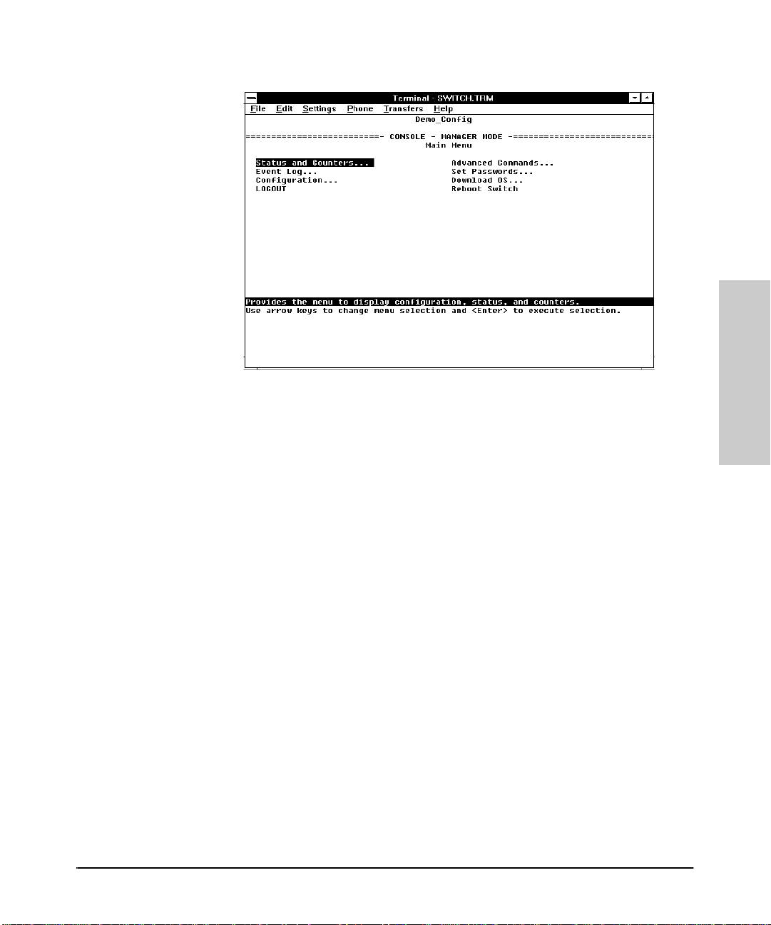
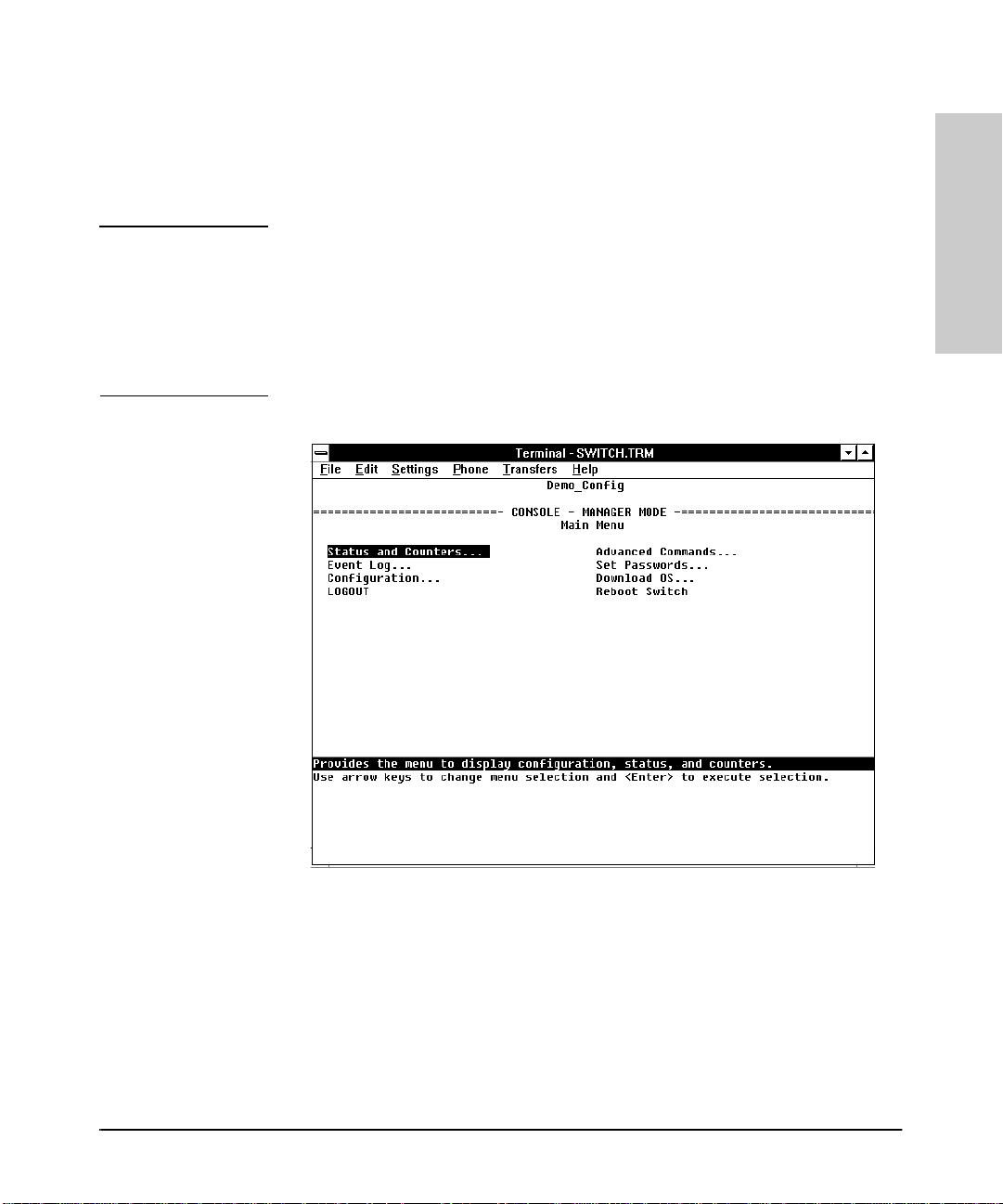
Starting and Ending a Console Session
Using the Console Inter face
Figure 2-1. The Main Menu
For a description of Main Menu features, refer to “Main Menu Features” on
page 2-4.
Using the Console Interface
How To End a Cons ole Session:
1. If you have not made configuration changes in the current session, go to
step 3.
2. Configuration changes requiring a reboot of the switch are indicated by
an asterisk (*) next to the configured item in the Configuration menu. (See
“Rebooting To Activate Configuration Changes” on page 2-11) If you have
made configuration ch an ges that require a reboot of the switch in order
to take effect:
a. Return to the Main Menu.
b. Us e the arrow keys ( [<] , [>] , [v] , and [^] ) to highlight Reboot Switch
in the Main Menu and press [Enter] to reboot.
3. Do one of the following:
• If you have accessed the switch through a direct connection from a
terminal device, exit from the terminal application.
• If you have accessed the switch through Telnet or a modem connec-
tion:
i. Return to the Main Menu.
ii. Highlight LOGOUT in the Main Menu and press [Enter].
2-3
Page 44

Using the Console Interface
Using the Console Interface
Main Menu Features
Main Menu Features
The Main Menu (figure 2-1 on page 2-3) gives you access to these console
interface features:
• Status and Counters: Displays information on the switch,
individual ports, the address tables, protocols and spanning tree.
(Refer to chapter 4, “Monitoring and Analyzing Switch Operat ion from
the Console”.)
• Event Log: Enables you to read progres s and error messa ges that
are useful for checking and troubleshooting switch operation. A
listing of Event Log messages is included on the CD shipped with your
switch. (Refer to “Event Log” on page 4-15.)
• Configuration: Enables you to display the current configuration
settings and to reconfigure individual parameters. (Refer to chapter
3, “Configuring the Switch ”. )
• LOGOUT: Disconnects Telnet or modem access to th e switch. (Refe r
to “How To End a Console Session” on page 2-3.)
• Advanced Commands: Provides access to a set of system manage-
ment, monitoring, and troubleshooting commands. (Refer to chapter
6, “Using the Advanced Commands”.)
• Set Passwords: Enables you to set Operator and Manager pass-
words to help r estrict who has access to th e console interface. (Refer
to “Using Password Security” on page 2-7.)
• Download OS: Enables you to downl oad a new software versi on to
th e sw i t c h . ( R e fe r to c h a p t e r 8 , “ F i l e T r a n s fe rs ” . )
• Reboot Switch: Performs a software reboot, which is required (in
some cases) to activate configuratio n ch an ges that have been made.
(Refer to “Rebooting To Activate Configuration Changes” on page
2-11.)
2-4
Page 45

Actions Line
Using the Console Inter face
Screen St ructure and Navigation
Screen Structure and Navigation
Console screens in clu d e th ese three elements:
■ Parameter fields and/or read-only information such as statistics
■ Navigation and configuration actions, such as Save, Edit, and Cancel
■ Help banner to describe navigation options and individual parameters.
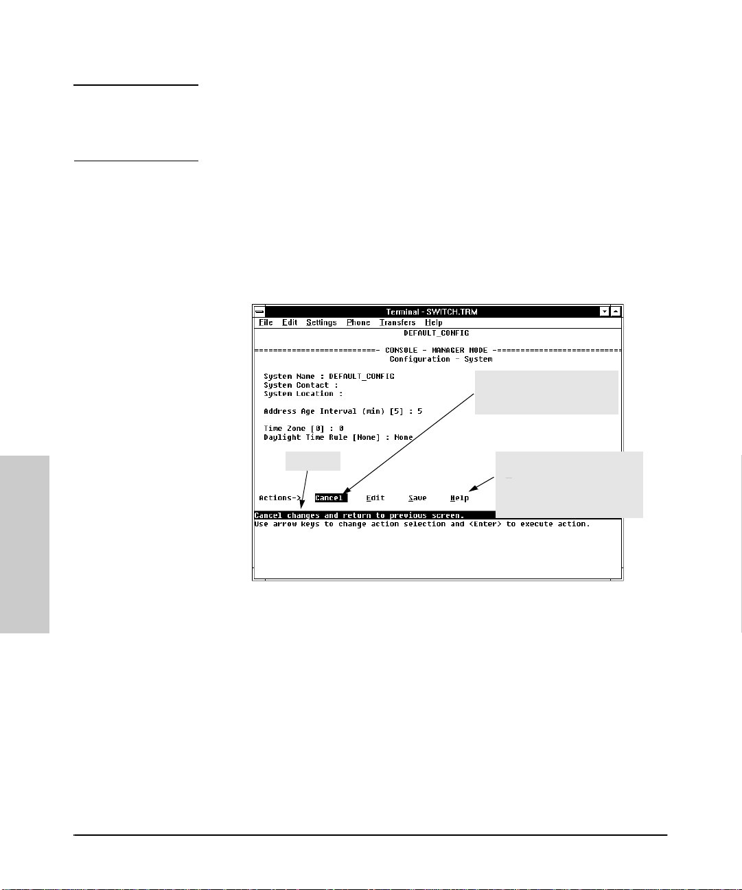
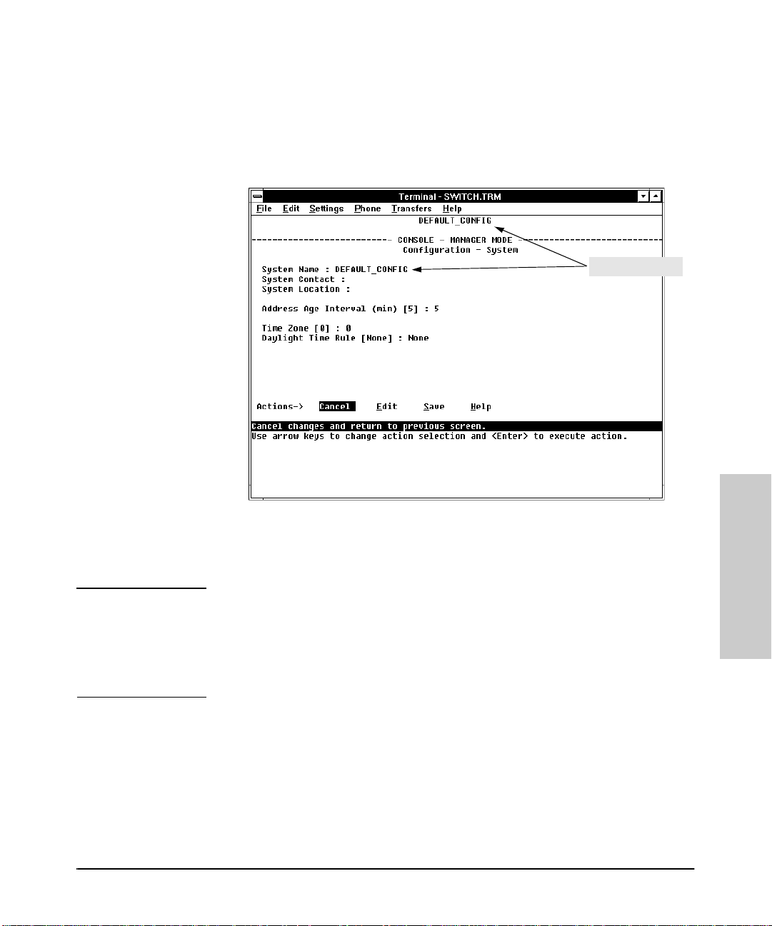
For example, in the System configur ation screen:
Using the Console Interface
System N ame
Parameter Fields
Help Banne r
Describing the
Select ed Acti on
(in this Case, the
Cancel O ption)
Help Describing Each of t he
Items in t he Parame ter Menu
Navigation I nstructions
Figure 2-2. Elements of Screen Structure
2-5
Page 46

Using the Console Interface
Screen St ructure and Navigation
Table 2-1. How To Navigate in the Console
Task: Actions:
Using the Console Interface
Execute an ac tion from an
“Actions-[>] menu:
Reconfigure (ed it ) a param e ter
setting or a field:
Use either of the following methods:
■ Use the arrow keys ( [<] , [>] , [v] , or [^] ) to
highlight the action you want to execute, then
press [Enter].
■ Press the key correspondi ng to the capit al let ter
in the action name. For example, in a configuration menu, press [E] to begin editing parameter
values.
1. Select a configuration area, such as System. (See
figure 2- 2.)
2. Press [E] (for E
3. Use [Tab] or the arrow keys ([< ], [>], [^], or [v ]) t o high light
the item or field.
4. Do one of the following:
• If the par ameter has preconfigured values, use the
Space bar to select a new option
• If there are no preconfigured values, type in a value.
5. If y ou want to cha nge anothe r para meter value, retur n to
step 3.
6. If you 're finished editing parameters in the displayed
screen, press [Enter] and do one of the following:
• To save any configu ration chang es you have made (or
if you have made no change s), p ress [S] (for the Save
action).
• To exit from the screen without saving any changes
that you have made, press [C] (for Cancel).
Note:
Some paramet er chan ges are act ivat ed when y ou
execute Sa ve, and i t i s theref ore no t nece ssary to reboot
the swit ch after makin g thes e change s. But i f an asteris k
appears nex t to any menu item you reconfigure, it is
necessary to reboot the sw itch to impl ement the ch ange.
In this case, rebooting should be done after you have
made all desi red ch ange s a nd th en ret ur ned t o t he Mai n
Menu.
7. When you are finished editing parame ters, return to the
Main Menu.
8. If nece ssary, reboot the switch by highlighting Reboot
Switch and pressing [Enter]. (Refer to the
dit on the Actions line).
Note
, above.)
2-6
Exit from a read-only screen. Press [B] (for the Back action).
Page 47

Using the Console Inter face
Using Password Security
Using Password Security
There are two levels of console access: Manager and Operator. For security,
you can set a password on each of these leve ls.
Level Action s P er m it te d
Manager: Access to all console interface areas. This is the default level. (Tha t is, if a
Manager password has
session , then anyone having access to the console can access any area of
the console interface.)
Operator: Access to the Status and Counters, Even t Log, and minimal Configuration
areas for display only.
Use of the LOGOUT command.
On the Operator level, the Command Prompt, Set Passwor ds, Download OS,
and Reboot options are not available in the M ain menu.
To use password security:
1. Set a Manager password (and an Operator password, if applicable for your
system).
not
been set prior to starting the current console
Using the Console Interface
2. Exit from the current console session. A Manager password will now be
needed for full access to the console.
If you do steps 1 and 2, above, then the next time a console session is started,
the console interface will prompt for a password. Assuming that both a
Manager password and an Operator password hav e been set, the level of
access to the console interface will be determined by which password is
entered in response to the prompt.
If you set a Manager password, you may also want to configure the
Connection Inactivity Time parameter in the Serial Link configuration
screen (page 3-16 ). This caus es the consol e session to end after the speci fied
period of inactivity, thus giving you added security against unauthorized
console access. (Once a Manager password is set and the console sessi on is
ended, access to the full cons o le in ter f ace for any subsequent sessions
requires the Manager password t o be entered .)
2-7
Page 48
Using the Console Interface
Using Pas sw ord Security
Note If there is only a Manager password set (with no Operator password), and the
Manager password is not entered co rrectly when the co nsole sess ion begin s,
the switch operates on the Operator level.
If there are both a Manager pas sword and an Operator password, but neit her
is entered correctly, access to the console will be denied.
If a Manager password is not set, anyone having access to the console
interface can operate the console with full manager privileges, regardless of
whether an Operator password is set.
Passwords are case-sensitive.
The rest of this section covers how to:
■ Set a Password
■ Delete a Password
■ Recover from a Lost Password
To set Manager and Operator pass w ords:.
Using the Console Interface
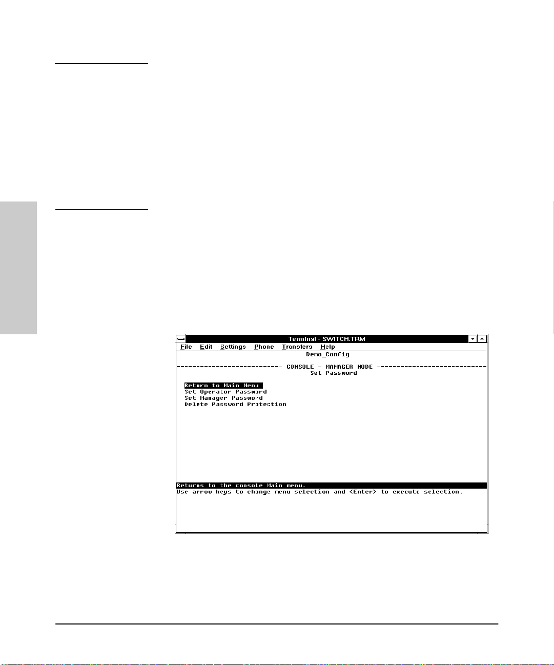
1. From the Main menu select Set Passwords. This screen appears:
Figure 2-3. The Set Password Screen
2. To set a new password:
a. Select Set Manager Password or Set Operator Password.
You will then be prompted with Enter new password.
2-8
Page 49

Using the Console Inter face
Using Password Security
b. T yp e a password of up to 16 characters and press [Enter]. (Remember
that passwords are case-sensitive.)
c. When prompted with Enter new password again, retype the
new password and press [Enter].
d. To set another password, return to step 2a. Otherwise, go to step 3.
3. Select Return to Main Menu to exit from the Set Password screen.
After a password is set, if you use LOGOUT or reboot or reset the Switch 800T,
you will be prompted to enter the password to start a new console session.
To Delete Password Protection (Including Recovery from a Lost
Password): This procedure deletes both passwords (Manager and Opera-
tor). If you h ave p h ysical access to the sw itch , press the Config Clear button
to clear all password protection, then enter new passwords as described
earlier in this chapter. If you do not have physical access to the switch, you
will need the Manager password:
1. Enter the console at the Manager level.
2. From the Main menu select Set Passwords. You will then see the screen
shown in figure 2-3.
3. Select Delete Password Protection. You will then see the following
prompt:
Continue Deletion of password protection? No
4. Press the Space bar or press [Y] to select Yes, then press [Enter].
5. Press [Enter] to clear the Password protection messag e.
6. Select Return to Main Menu to exit from the Set Password screen.
To Recover from a Lost Manager Pass word:
If you cannot start a console ses sion at the manager level because of a lost
Manager password, you can clear t he password by getting physical acces s to
the switch and pressing and holding the Config Clear button for at least one
second.
Using the Console Interface
2-9
Page 50
Using the Console Interface
Using the Console Interface
Rebooti ng the Switch
Rebooting the Switch
Rebooting the switch terminates the current console session and performs a
reset of the operating system. Some of the reasons for performing a reboot
include:
■ Activating certain configuration changes that require a reboot
■ Resetting statistical counters to zero
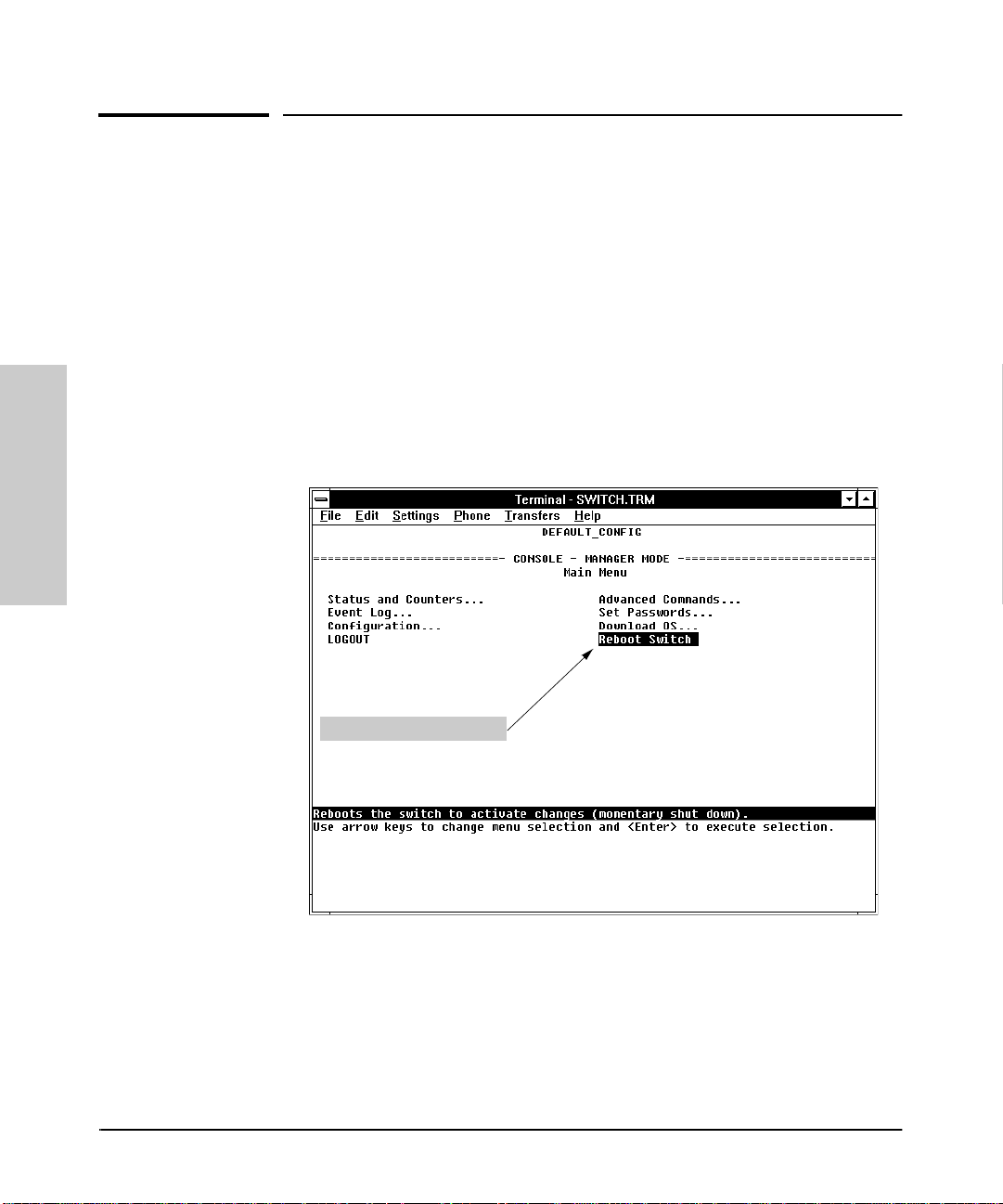
To Reboot the switch, use the Reboot Switch option in the Main menu. (If
a Manager password has been previously set, Reboot Switch appears only
if this password is entered at the beginning of the console session.)
2-10
The Reboot Sw itch Optio n
Figure 2-4. The Reboot Swit ch Option in the Main Menu
Page 51
Using the Console Inter face
Rebooting the Switch
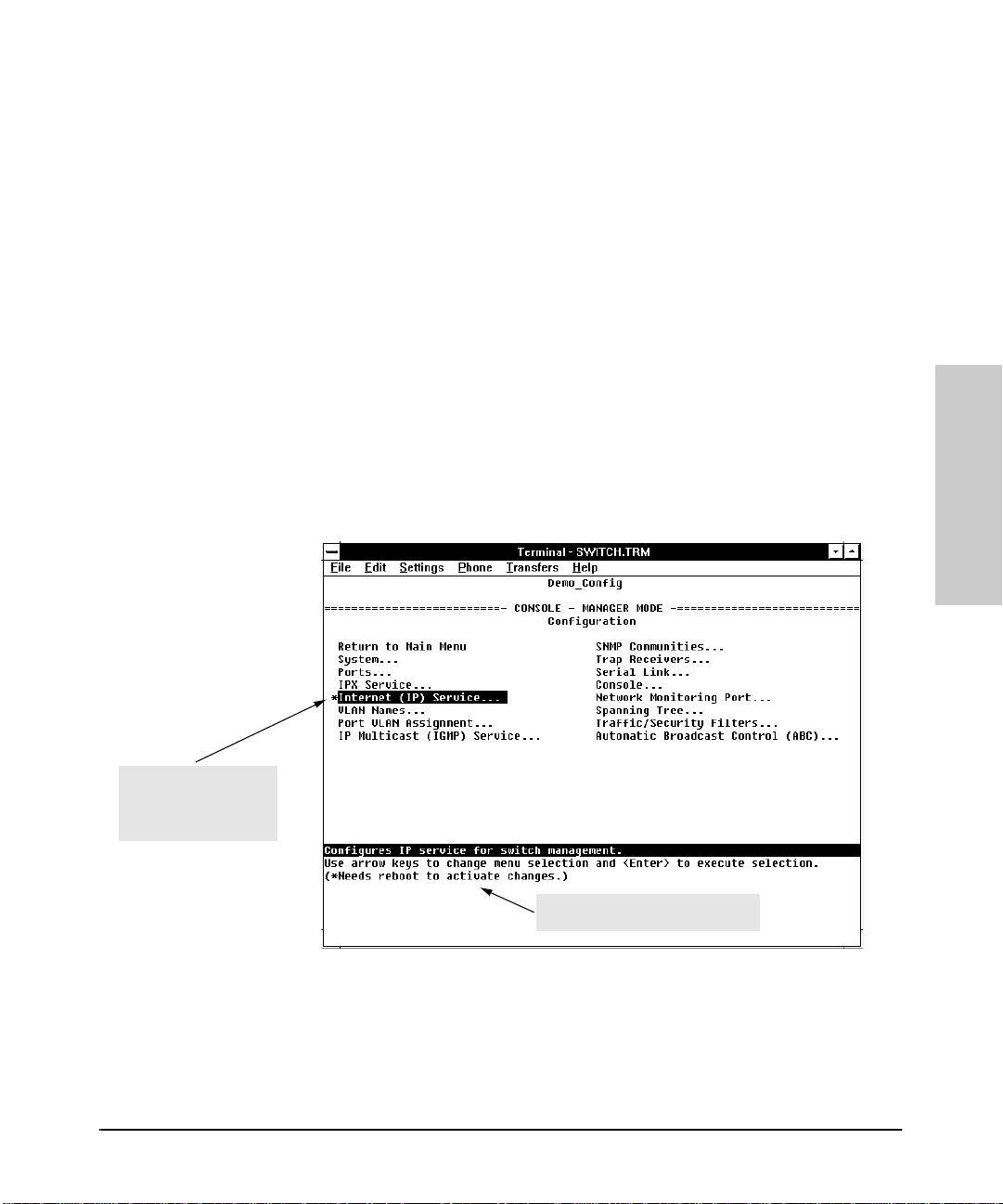
Rebooting To Activa te Configur a tion Changes . Configuration changes
for some parameters become effective as soon as you save them. However,
you must reboot the switch in order to implement any changes to any
parameters in the following areas:
■ IPX Service
■ Internet (IP) Service
■ Serial Link
■ Console Parameters
■ New VLAN Names
■ System Parameters
If configuration changes requiring a reboot have been made, the switch
displays an aster isk nex t to the con figu ration menu i tem in which th e change
has been made. For ex ample, if you change a nd save paramet er values for the
switch’s IP configuration, the need for rebooting the switch would be
indicated by an asterisk appearing in the following screen:
Using the Console Interface
Asterisk indicates a
configuration change
that requires a reboot
in order to take effect.
Reminde r to reboot the swit ch to
activat e configuration changes.
Figure 2-5. Example of a Configuration Change Requiring a Reboot
2-11
Page 52

Using the Console Interface
Using the Console Interface
Resetti ng th e S witc h
Resetting the Switch
Resetting requ ires physical access to th e front of the Switch 800T. There are
two levels of reset:
■ Hardware reset: Momentarily interrupts switch operation, performs a
complete hardware self- t est. This also clears the Event Log.
■ Configuration reset: This is a drastic action that inte rru p t s switch
operation, clears any passwords, clears the event log, performs a complete self-test, and reboots the switch in its factory default configuration.
You should consider performing a configuration reset only if you want all
configurable parameters reset to the factory default values.
To perfor m a hardware or config uration r eset: Refe r to the table on page
D-5 in appendix D, “Switch Reference”.
2-12
Page 53

Configurin g the Switch
Overview
This chapter provid es an overview o f the Swit ch 800T confi gura tion featur es.
In its factory default configuration, the Switch 800T aut omatically operates as
a multiport learning bridge with network connectivity provided by the
particular modules that you have installed. However, to “fine-tune” your
switch for the specific performance and security needs in your network, you
may choose to reconfigure cer tain switch parameters.
Configuration Features. The Switch 800T enables you to configure the
following switch features. For information on individual configurati on
parameters, use the online Help provided with each configur ation screen in
the console user interface.
■ System (page 3-5)
■ Ports (page 3-6)
■ IPX Service (page 3-7)
■ Internet (IP) Service (page 3-9)
■ SNMP Communities (page 3-13)
■ Trap Receivers (page 3-15)
■ IP Multicast (IGMP) Service (page 3-12)
■ Serial Link (page 3-16)
■ Console (page 3-17)
■ Spanning Tree (page 3-21)
■ Traffic/Security Filters (page 3-22)
■ Virtual LAN (VLAN) (page 3-11)
■ Network Monitoring Port (page 3-18)
■ Automatic Broadcast Control (ABC) (page 3-23)
3
Configuring the Switch
3-1
Page 54
Configu ring the Switch
Overview
Note In the factory default configuration, the Spanning Tree Protocol (STP) is off.
However, if the topology of your network includes any redundant loops
between switches or bridges, you should enable STP. See “Spanning Tree”
(page 3-21).
To get Help on indi vidu al parameter descripti ons. In all screens except
the Advance Commands screen t here is a Help option in the Actions menu .
Whenever the Actions menu is active, you can display Help for that screen’s
parameters by pressing [H]. (The Actions menu is active whenever any of the
choices in the Action menu is highlighted.) For example:
Highlight on any item in the
Actions menu indicates that
the Action s me nu is active.
Configuring the Switch
3-2
Banner
Pressing [H] or highlighting
H
elp and pressing [Enter]
displays Help for the
parameters listed in the upper
part of the screen.
Figure 3-1. Example Showing How To Display Help
To get Help on the actions or data fields in each screen: Use the arrow
keys ( [<], [>], [^], or [v]) to select an action or data field. The banner under the
action items will describe the currently selected action or data field. (For
guidance in how to navigate in a configuration screen, see the instructions
provided at the bottom of the screen, or refer to “Scre en Structu re and
Navigation” on page 2-5.)
Page 55
Configuring the Switch
Configurable Features
Configurable Fea ture s
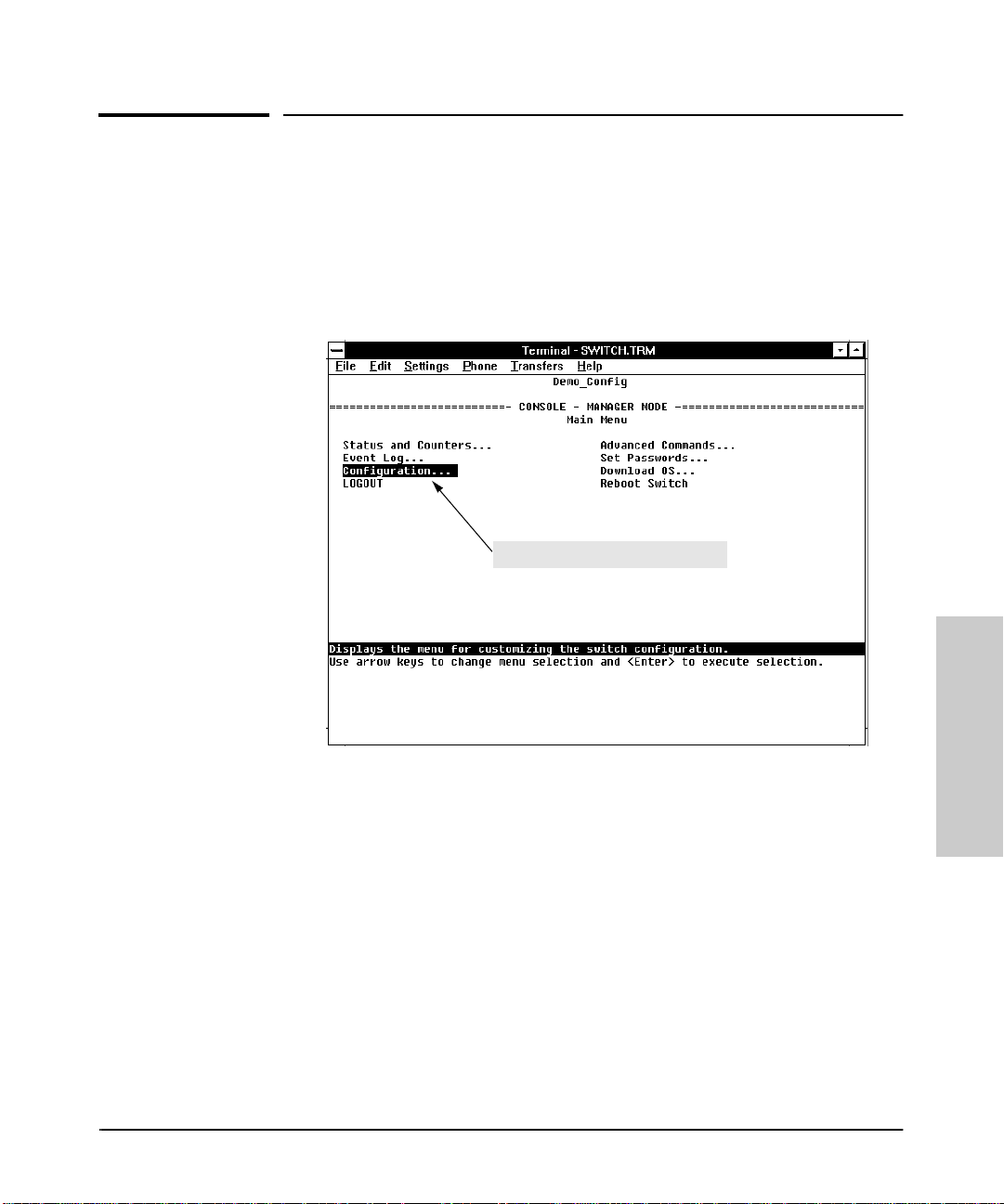
How To Access the Switch 800T Configuration: Use this procedure to
access the switch’s configu r ab le features.
1. Begin at the Main Menu and select Configuration (figure 3-2):
Access to Configurable Features
Figure 3-2. Select “Configuration” in the Main Menu
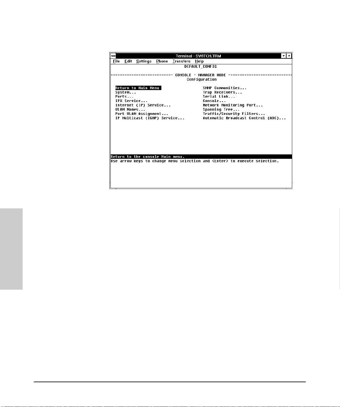
After you select Configuration, the Configuration menu appears as
shown in (figure 3-3).
Configuring the Switch
3-3
Page 56
Configu ring the Switch
Configurable Features
Configuring the Switch
Figure 3-3. The Configuration Menu
2. Use the arrow keys ( [<], [>], [^], and [v] ) to highlight the configuration
topic you want, then press [Enter].
3. Refer to the appropriate sections in the remainder of this chapter for
information on config uring specific features.
3-4
Page 57
Configuring the Switch
Configurable Features
System Features
Configures basic switch management information, including system data,
address aging, and time zone parameters:
System Name
Figure 3-4. The System Confi guration Screen (Defa ult Values)
Note To help simplify administration, it is recommended that you configure
System Name to a character string that is meaningful with in yo u r system.
To set the time and date, set the Time Protocol parameters under “Internet
(IP) Service Features” (page 3- 9) for your ti me server or use t he time and date
commands described in chapter 6.
Configuring the Switch
3-5
Page 58
Configu ring the Switch
Configurable Features
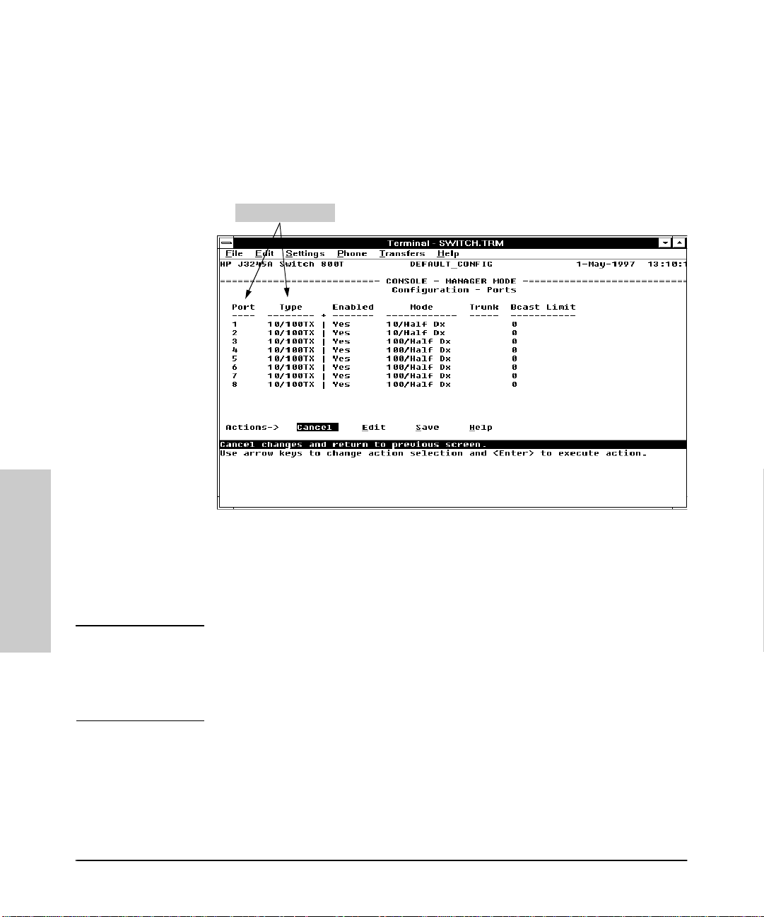
Port Features
Configures the operating state for each port and optionally assigns selected
ports to a port trunk. (For more on port trunking, refer to chapter 7.) Also
optionally enables you to restrict the amount of broadcast traffic on the port.
The read-only fields in this screen display the port names and port types.
Read - O n l y Field s
Configuring the Switch
Figure 3-5. Example of the Port Configuration Screen
Port names in the configuration correspond to port number on the front of the
switch.
Note Broadcast limit (the Bcast Limit parameter) can be set for all ports in the
switch (or VLAN, if VLANs are configured) from the Automatic Broadcast
Control (ABC ) screen (page 7- 30 and follow ing) if ABC is enabled. Se tting the
broadcast limit (Bcast Limit) in the above screen is on a per-port basis and
overrides any settings done in Automatic Broadcast Control.
3-6
Page 59
Configuring the Switch
Configurable Features
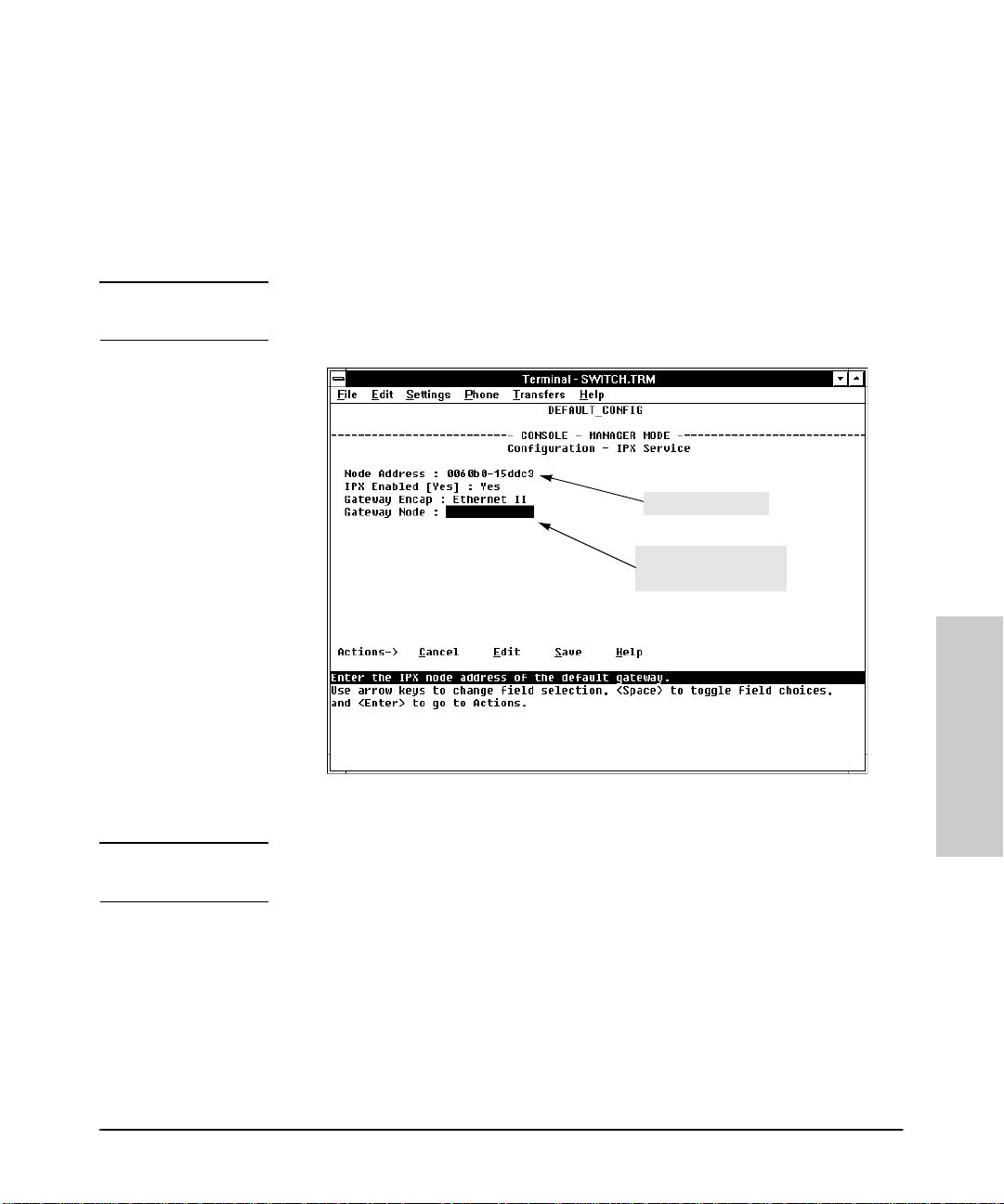
IPX Service Features
Enables the switch to be managed in an IPX ne twork. The Switch 800T
automatically enables IPX, configures the IPX node address, and learns the
IPX network number. Thus, in the factory default configuration, IPX is automatically enabled for the switch .
Note In this case, the factory-assigned node address is displayed as shown below.
(The switch automatically detects the IPX network number.)
Read-Only Field
Appears if Gate w ay
Encap Configured
Figure 3-6. The IPX Service Configuration Screen
Note If VLANs are configured, the above parameters appear in a horizontally
formatted screen.
You can also configure an IPX gateway frame encapsulation type an d gateway
node so that the switch can be managed from a remote IPX network.
If VLANs are configure d, the switc h can automatica lly learn the IPX netwo rk
number of each attached VLAN. For more on VLANs, refer to chapter 7,
“Advanced Concepts”.
Configuring the Switch
3-7
Page 60

Configu ring the Switch
Configurable Features
(Optional) How To Configure IPX for Management from a Remote IPX
Network. In the factory default, IPX is already enabled. If you want to
enable management from a remote IPX network, you must conf igu re the
gateway encapsulation type and gateway node.
1. From the Configuration screen, select IPX Service to display the above
screen.
2. If the IPX Enabled parameter is not already set to “Yes” (the fact ory
default), then select thi s parameter and press the Space bar to s elect Yes.
3. Select the Gateway Encap fiel d and use the Space bar to select the
appropriate gateway encapsulation for the gateway device.
4. Press [v] to display and select the Gateway Node field.
5. Type the IPX node address (MAC address) of the gateway device that is
using the encapsulation defined in step 3.
Configuring the Switch
6. Press [Enter], th e n [S] (for S
ave).
7. Return to the Main Menu and reboot the switch.
3-8
Page 61

Configuring the Switch
Configurable Features
Internet (IP) Service Features
Enables you to configure:
■ IP address, subnet mask, and (optionally) the gateway address for the
switch so that it can be managed in an IP network
■ The time server information (used if yo u want the switch t o get it s tim e
information from another device operating as a Timep server)
You can manually configure an IP address, subnet mask, and a Gateway IP
address by setting the IP Config parameter to Manual. Or, you can use
Bootp to configure IP for the switch from a Bootp server. In this case you must
also configu re your Bootp server acco rdingly. If you plan to use Bootp, refer
to appendix E, “Bootp Operation”. Otherwise, set the IP Config parameter
to Manual and then manually enter the IP address and subnet mask you want
for the Switch 800T.
The default setting for Ti m e
Protoc ol Enabled is No.
Setting it to Yes as show n
here, then p ressing [v] or [Tab]
causes t he Timep Server
Address and Timep Poll
Interval parameter s to
appear. For descriptions of
these parameters, refer to
the online Help for thi s
screen.
Configuring the Switch
Figure 3-7. Example of the I P Service Configuration Screen
If VLANs are conf igured, then enable IP on a “per VLAN” basi s. This is because
each VLAN is a separate network and requires a unique IP address, plus a
subnet mask. A gateway (IP) address is optional. For more on VLANs, refer
to “Virtual LAN (VLAN) Features” on page 3-11 and in chap ter 7, “Advanced
Concepts”.
3-9
Page 62

Configu ring the Switch
Configurable Features
How To Manual l y Configure for IP.
1. From the Configuration screen, select Internet (IP) Service to
display the above screen.
2. Press [E] (for E
dit).
3. Select the IP Config field and use the Space bar to select Manual.
4. Select the IP Address field and enter th e IP address you want to assign
to the switch.
5. Select the Subnet Mask field and enter the subnet mask for the IP
address.
6. If you want to reach off-subnet destinations, select the Gateway field
and enter the IP address of the gateway router.
7. Press [Enter], the n [S] (for S
ave).
8. Return to the Main Menu and reboot the switch.
Configuring the Switch
3-10
Page 63

Configuring the Switch
Configurable Features
Virtual LAN ( VL A N) F eatures
Enables you to create up to eight port-based VLANs. A VLAN is a group of
ports designated by the Switch 800T as belo n ging to the same broadcast
domain. This feature enables you to configure port-based virtual LANs to help
isolate broadcas t traffic and increase securit y. T yp ically, if VLANs are used,
all ports carrying traffic for a particular subnet address should be configured
to the same VLAN. For more on when, why, and how to use VLANs, refer to
“Virtual LANS (VLANs)” on page 7-14.
In the factory defaul t sta te, VLANs are not configur ed. All ports b elong to the
same broadcast/multicast domain. This domain is called “DEFAULT_VLAN”
and appears in the “VLAN Names” screen. You can create up to seven additional VLANs by adding new VLAN names, and then assigning one or more
ports to each VLAN. (The switch accepts a maximum of eigh t VLANs, including the defau lt V LAN.) Note that each port can be as signed to onl y one VLAN.
DEFAULT_VLAN can be rena med, but not delet ed. Any ports not specific ally
assigned to another VLAN wi ll remain assigned to DEFAULT_VLAN.
Note Befor e you delete a VLAN, you must re-assign its ports to another VLAN.
When VLANs are used, and are managed from an SNMP workstation, you
should configure the IPX and/or IP services for each VLAN. (Refer to pages
3-7 and 3-9.)
Spanning T ree protocol (STP), ABC, IGMP, and some o ther features o perate
on a “per VLAN” basis. This means you must configure such features separately for each VLAN in which you want them to operate.
For more information on VLANs and how to configure them, refer to “Virtual
LANs (VLANs)” on page 7-14.
Configuring the Switch
3-11
Page 64

Configu ring the Switch
Configurable Features
IP Multicast (IGMP) Service Features—Multimedia
Traffic Control
The IGMP (Internet Group Management Protocol) feature helps to reduce
network congestion and improve security by reducing unnecessary multicast
traffic on a per-port basis. This is useful in multimedia applications such as
LAN TV, desktop conferencing, and collaborative comput in g, where there is
multipoint communication; that is, communication from one to many hosts,
or communication originating from many hosts and destined for many other
hosts. In such multipoint applications, IGMP will be configured on the hosts,
and multicast traffic will be generated by one or more servers (inside or
outside of the local network). Switches in the network (such as the Switch
800T or the B-version of the Switch 2000) can the n be configured to direct the
multicast traffic to only the ports where needed.
In the factory default state (IGMP disabled), the swit ch forwar ds all IGMP
traffic. When IGMP is enable d, you can conf igu re the switch to any of the
following states on a per-port basis:
■ Automatic (the default) : Causes the switch to interpret IGMP packets and
to filter IP multicast traffi c based on the IGMP packet information for that
port.
■ Blocking: Causes the switch to drop all IGMP transmissions received and
block all outgoing IP Multicast packets for that port.
■ Forwarding: Causes the switch to forward all IGMP and IP multicast
transmissions through the port.
Configuring the Switch
For more information on IGMP and how to configure it, refer to “IP Multicast
(IGMP)” on 7-23.
3-12
Page 65
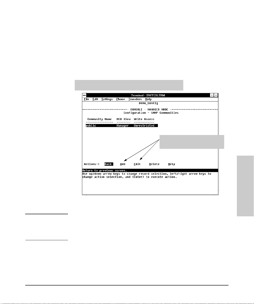
Configuring the Switch
Configurable Features
SNMP Communities Fe atur es
Enables you to add, edit, or delete SNMP communities. Use this feature if you
expect to manage the switch from an SNMP management statio n . You can
configure up to five SNMP communities , each with ei ther an operato r-level or
a manager-level view, and either restri cted o r unres tricted wri te acc ess. (F or
more on this topic, refer to chapter 5, “Using SNMP To Monitor and Manage
the Switch”, and to the online Help.)
This screen gives an overview of the SNMP communities that are
current ly configur ed. All fields in this screen are read-only.
Add and E dit o ptions are used to mo dify
the SNMP options. See figur e 3- 9.
Figure 3-8. The SNMP Communities Screen (Default Values)
Caution Deleting the community named “public” disables many network management
functions (such as auto-discovery, traffic monitoring, and threshold setting).
If security for network management is a concern, it is recommended that you
change the write access for the “publ ic” community to “Restricted”.
How To Configure for SNMP Communities.
Ensure that the switch has been configured for IP and/or IPX.
1. From the Configuration screen, select SNMP Communities to display a
screen similar to the one above.
3-13
Configuring the Switch
Page 66
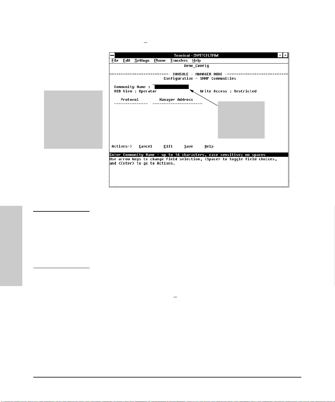
Configu ring the Switch
Configurable Features
If you are adding a
community, the field s in
this scree n are blank.
If you are edit ing an
existing community, the
values for the currently
selected Community
appear in t he fields.
2. Press [A] (for Add) to display the following screen:
Type the value f or
this field
use the Space bar
to select val ues fo r
other fields
Figure 3-9. The SNMP Add or Edit Scre en
Configuring the Switch
Note In the default configuration, no manager addresses are configured. In this
case, all manag ement stati ons using the cor rect community n ame may access
the switch with the correspondin g View and Access levels. If you want to
restrict access to one or more specific nodes, you can enter up to ten IP and/
or IPX addresses of such nodes in to the Manager Add ress fie ld. Ente ring one
or more IP or IPX addresses in the Manager Address field li mits access to only
those addresses.
3. Enter the appropriate value in each of the above fields (use the [Tab] key
to move from one field to the next).
4. Press [Enter], then [S] (for S
3-14
ave).
Page 67

Configuring the Switch
Configurable Features
Trap Receivers Features
Enables you to configure up to ten IP and/or IPX management stations (trap
receivers) to receive SNMP trap packets sent from the switch. Trap packets
describe specifi c event types. (These ev ents are the same as the log mes sages
displayed in the event log.) The protocol, address, and communit y d efin e
which management st atio n s receive the traps. An authentication trap is sent
and the Security LED on the front panel of the switch begins flashing if a
management station attempts an unauthorized access. (The ClearLED
command turns off the Security LED—page 6-6. ) Check the event log to hel p
determine why the authentica tio n t ra p was sent . (Refer to chapter 4 for
information on the event log. )
Figure 3-10. The Trap Receivers Configuration Screen (Def ault Values)
Configuring the Switch
3-15
Page 68
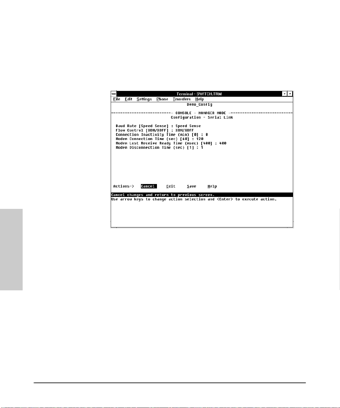
Configu ring the Switch
Configurable Features
Serial Link Features
Enables you to adjust the Console RS-232 configuration to customize the
connection with the PC, terminal , or modem you are using for console access.
Refer to the online Help for information on modem settings. Refer also to
“Console Features ” on page 3-17.
Configuring the Switch
Figure 3-11. The Serial Link Configuration Screen (Defau lt Values)
3-16
Page 69
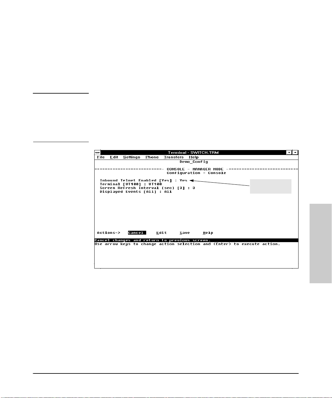
Configuring the Switch
Configurable Features
Console Fea tur es
Lets you enable or disable inbound Telnet access and control the types of
events displayed in th e even t lo g. Also specifies the terminal type and the
console screen refres h interval used by the statistics screens (that is, the
frequency with which statistics are updated on the statistics screens).
Note “Inbound” Telnet is Telnet access to the switch consol e from another device.
“Outbound” Telnet, which is using Telnet through the switch console to access
another device, is always enabled as long as the switch has been configured
with a valid IP address. (To configure an IP address for the switch, refer to
“Internet (IP) Service Features” on page 3-9.) The switch supports one
inbound and one outbound Telnet session simultaneously.
Default Inbound
Telnet Setting
Figure 3-12. The Console Configuration Screen (Default Values)
Configuring the Switch
3-17
Page 70
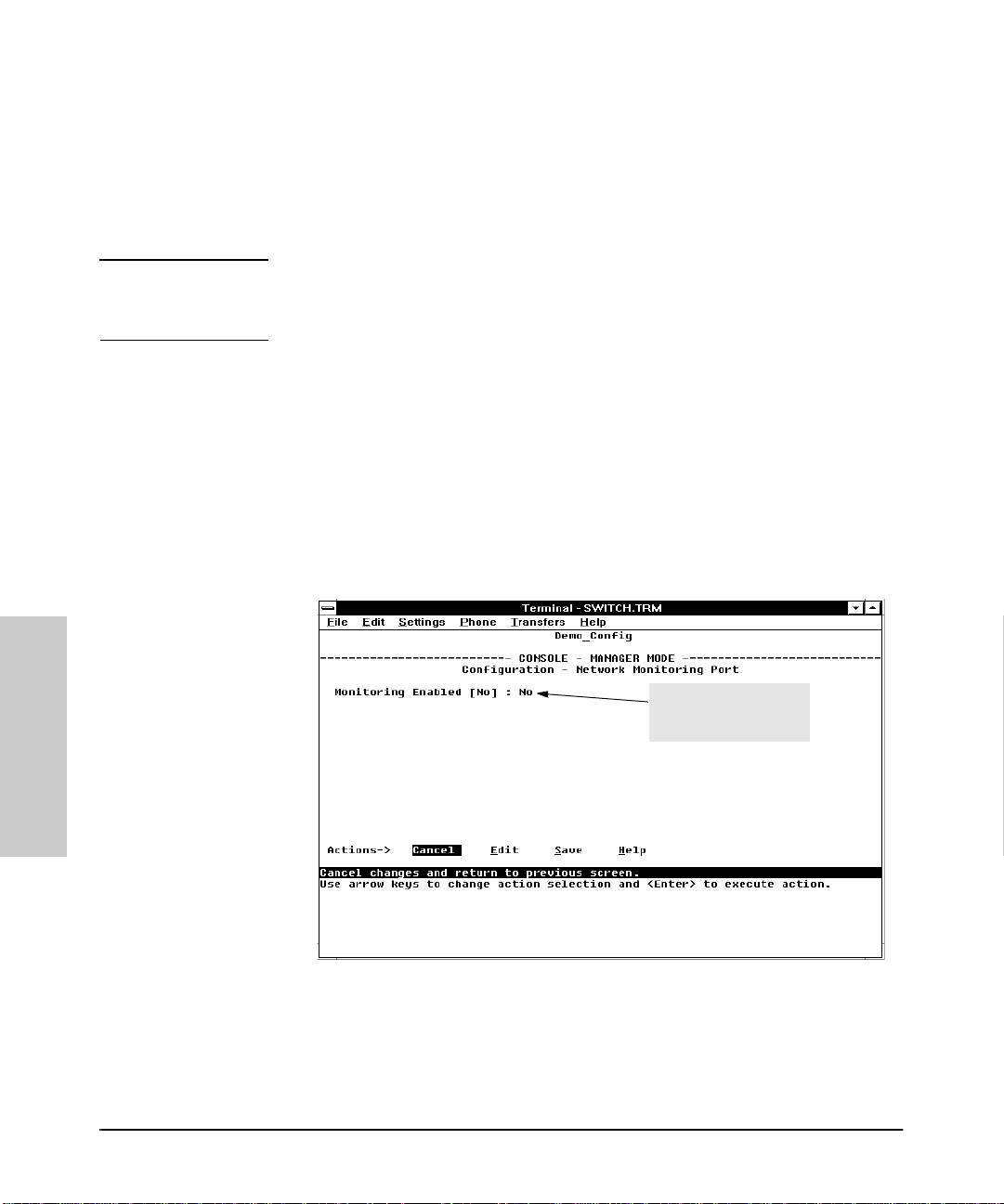
Configu ring the Switch
Configurable Features
Network Monitorin g Por t Features
Lets you designate a port for monitoring traffic on one or more other ports or
on a VLAN configured on the switch. This is accomplished by copying all
traffic from the specified ports or VLAN to the designated monitoring port.
Note If Automatic Broadcast Control (ABC) is configured and more than one port
is being monit ored, then broad cast packets may be duplicated on the monitor
port.
How To Configure for M onitoring: This procedure describes configuring the switch for monitoring when monitoring is disabled. (If mo nito ring has
already been enabled, the screens will appear differently than shown in this
procedure.)
1. Select Network Monitoring Port from the Configuration screen.
2. In the Actions menu, press [E] (for Edit).
3. If monitoring is currently disabled (the default) then enable it by pressing
the Space bar (or [Y] ) to select Yes.
Configuring the Switch
Enable Monitoring by
Settin g this Parameter
to “Yes”
Figure 3-13. The Default Network Mon itoring Configuration Screen
4. Press [v] to display a screen si milar to the fol lowing an d move the cursor
to the Monitoring Port parameter.
3-18
Page 71
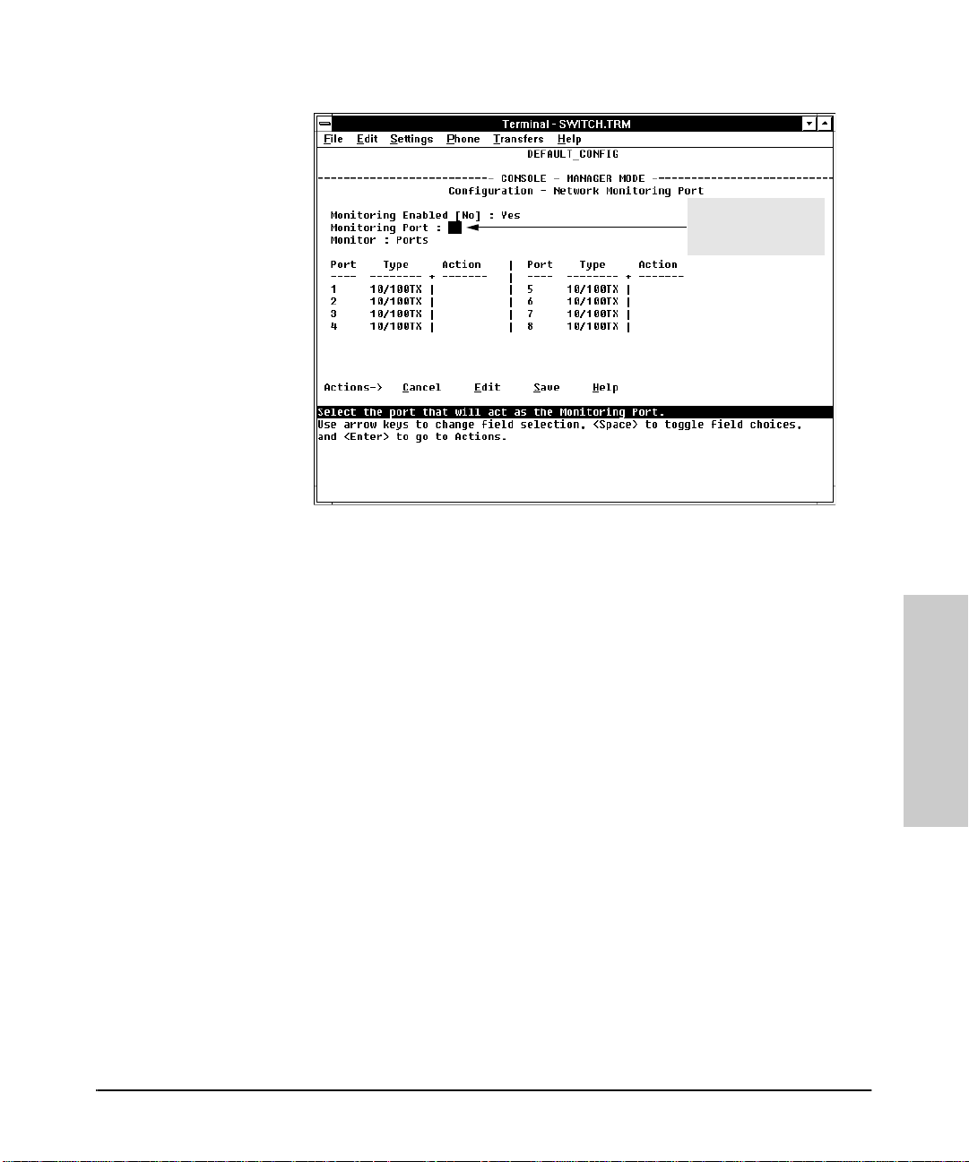
Configuring the Switch
Configurable Features
Move the Cursor to
the Monitoring Port
Parameter
Figure 3-14. Example of Selecting a Monitoring Port
5. Press the Space bar to select which port to use for the monitoring port,
then press [v] to move to the Monitor parameter. (The default setting
is Ports, which you will use if you want to monitor one or more individual
ports on the switch.)
Configuring the Switch
6. Do one of the following:
• If you want to monitor individual ports, leave the Monitor param-
eter set to Ports and press [v] to move the cursor to the Action
column for the individual ports. Press the Space bar to select Mon-
itor for each port that you want monitored. (Use [v] to move from
one po rt to the ne xt in th e Action column. ) Wh en you a re fi nished,
press [Enter], then press [S] (for Save) to save your changes and exit
from the screen.
• If, instead of individual ports, you want to monitor all of the ports in
a VLAN, press the S p ace b ar to select VLAN in the Monitor parameter, then press [v] to move to the VLAN parameter (figure 3-15) . Then
press the Space bar again to select the VLAN that you want to monitor.
When you are finished, press [Enter] , then press [S] (for Save) to save
your changes and exit from the screen.
7. Return to the Main Menu.
3-19
Page 72
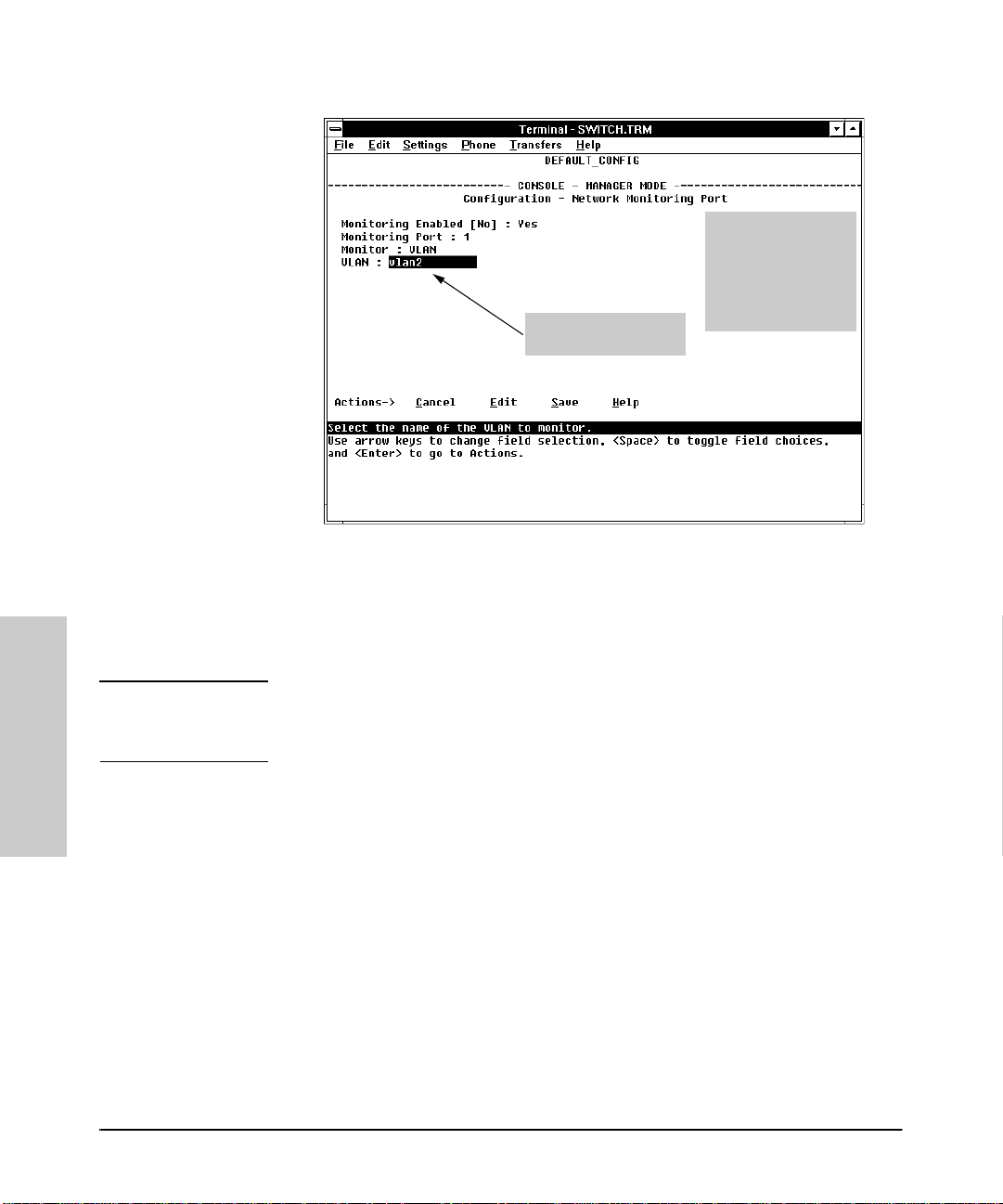
Configu ring the Switch
Configurable Features
Note:
This screen appears
instead of the one in
figure 3-14 if th e
Monitor paramet er is
set to VLAN
Example of a VLAN
Monitoring Parameter
Figure 3-15. Example of Selecting a VLAN to Monitor
Configuring the Switch
Note It is possible in networks with high traffic levels to copy more traffic to a
monitor port than the link can support. In this situation, some packets may
not be copied to the monitor port.
3-20
Page 73

Configuring the Switch
Configurable Features
Spanning Tree Featu r es
Enables you to activate the IEEE 802.1d Spanning Tree Protocol (STP) and to
adjust spanning tree parameters. In the factory default, STP is off. Thus, if
there are any redundant paths (loops) between nodes in your network, you
should set the Spanning T ree Enabl ed para meter to Yes. Thi s ensu res that al l
redundant ports (those providing backup parallel connections) are in a blocking state and not used to forward data. In the event of a topology change such
as a switch, b ridge, or data link fai lure, STP d evelops a new spanning tr ee that
may result in changing some ports from the blocking s tate to the forwarding
state.
If VLANs are configured, then yo u can conf igu r e S TP separ ately for each
VLAN.
Caution Because the switch automatically gives faster links a higher priority, the
default STP parameter settin gs are usually adequate for spanning tree
operation. Because incorrect STP settings can adversely affect network
performance, you should avoid making changes without having a strong
understanding of how STP operates. For more on STP, refer to chapter 7,
“Advanced Concep t s”, and examine the IEEE 802.1d standard.
The switch automatical ly senses port identity and type, and automatically
defines port cost and prio rity for each type. The inte rface allo ws you to adju st
the Cost and Priority for each port, as well as the global STP parameter values
for the switch.
To configure STP, ref er to “Spann in g Tree Protocol (STP)” on page 7-2.
3-21
Configuring the Switch
Page 74

Configu ring the Switch
Configurable Features
Traffic/Securi ty Fi lter Fea tur es
Enables you to c ontrol traffi c and increase netw ork security by creating filte rs
based on any of the following criteria:
■ Multicast address
■ Source port only
■ Source MAC address and source port
■ Protocol frame type
• IP (Ethernet or 802.3 SAP)
•ARP
•DEC LAT
• AppleTalk
•SNA
•NetBIOS
• IPX (Ethernet or 802.3 SAP)
• VINES IP or ECHO
If you are using VLANs, they will affect source port and source MAC filter
configuration. For more information on filtering, using filters with VLANs, and
configuring filters, refer to “Filters and Sec urity” on page 7-8.
Configuring the Switch
3-22
Page 75

Configuring the Switch
Configurable Features
Automatic Broadcast Control (ABC) Features—Layer 3
Switching
ABC reduces the amount of IP and/or IPX broadcast traffic on a network by
enabling the switch to serve as a proxy for the ultimate destination of broadcast IP ARP and RIP packets, and IPX NSQ, and RIP or SAP packets. This
reduces the number of ports over which IP and/or IPX broadcasts are sent,
increases the amount of network bandwidth available for other purposes, and
can reduce the need for routers withi n a network. These factors can lower
costs and reduce latency in the network. (While communication between
VLANs—broad cast domains—st ill requires a router, ABC functions within
VLANs and, by using multiple subnets per VLAN (multi-netting), can reduce
or eliminate the need for ro uters within the VLAN.)
When enabled, ABC also allo ws you to set the broadcast limit parameter
(Bcast Limit) in the Port Con fig uratio n screen ( figur e 3-5) for al l ports o n
the switch (or all po rts on the VLAN, if VLANs are configured and ABC is
enabled for the VLAN).
In the factory default state, ABC is disabled. For more infor mation on ABC
and how to configu re it, refer to “Automatic Br oadcast Control (ABC )” on page
7-30.
3-23
Configuring the Switch
Page 76

Page 77

Monitoring and Analyzing Switch Operation
from the Console
Overview
The Main Menu in t he switch’s console interface gives you access to the
following sources of read -o n ly d ata fo r hel pin g yo u to monitor, analyze, and
troubleshoot switch operation:
Table 4-1. Read-Only Monitoring and Analyzing Features
4
Main Menu
Item
Status and
Counters
Menus
Event Log Lists event messages generated by the switch.
Data Type Purpose
Switch Information Lists switch-level operating information.
Port Status Displays the operational status of each port.
Port Counters Summarizes port activity.
Address (forward ing) Table Lists the MAC ad dresse s of node s the swi tch has
detected on the network, along with the
corresponding switch por t.
Port Address Table Lists the MAC addresses that the switch has
Spanning Tree Information Lists Spanning Tree data for the switch and for
IP Multic ast (IGMP) Stat us Lists IGMP groups, report, query, and type of
Automatic Broadcast
Contro l (A B C ) In fo rm a ti on
learned from the selecte d port.
individua l ports. If VLANs are config ured, repo rts
on a per-VLAN basis.
device acce ss on ports. If VLANs ar e configur ed,
repo rts on a per-VLAN ba sis.
If VLANs are configured, reports on a per-VLAN
basis.
Switch Operation from the
Monitoring and Analyzing
4-1
Page 78
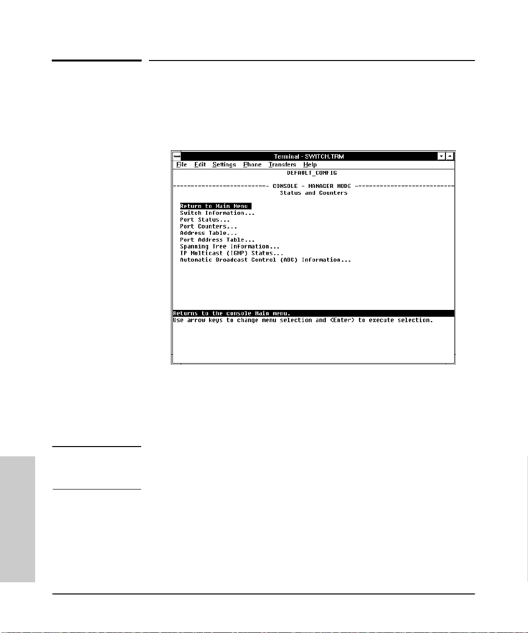
Monitoring and Analyzing Switch Operation from the Console
Status and Counters Menu
Status and Co unters Menu
Select Status and Counters from the Main Menu to display the Status
and Counters menu:
Figure 4-1. The Status and Counters Menu
Each of the above menu items accesses the read-only screens described on
the following pages. Refer to the online help for a description of the entries
displayed in these screens.
Note Spanning Tree, IP Multicast (IGMP), and Automatic Broadcast Control (ABC)
are reported on a per -VLAN bas is. Fo r thes e feat ures you w ill be promp ted to
select a VLAN if multiple VLANs are configured.
Monitoring and Analyzing
Switch Operation from the
4-2
Page 79
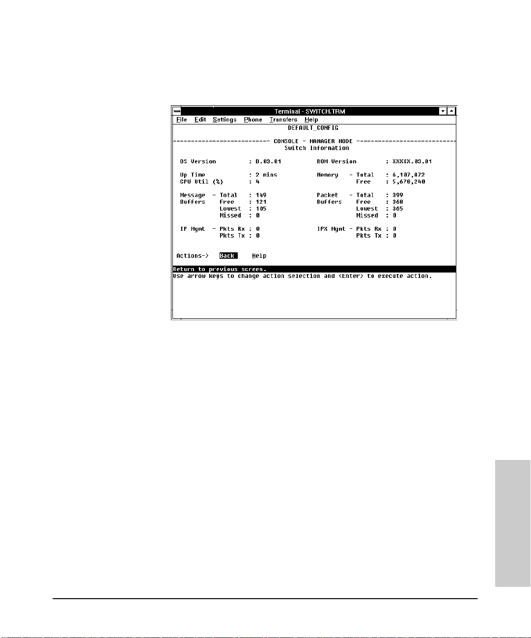
Monitor ing and Analyzing Switch Operation from the Console
Switch Information
Status and Co unters Menu
Figure 4-2. Example of Switch Information
This screen tells you which version of the OS (operating system) and ROM
(low-level star tup cod e lo cated in read- only m emory) the swit ch is usi ng, and
dynamically indicates how individual switch resources are being used.
4-3
Switch Operation from the
Monitoring and Analyzing
Page 80
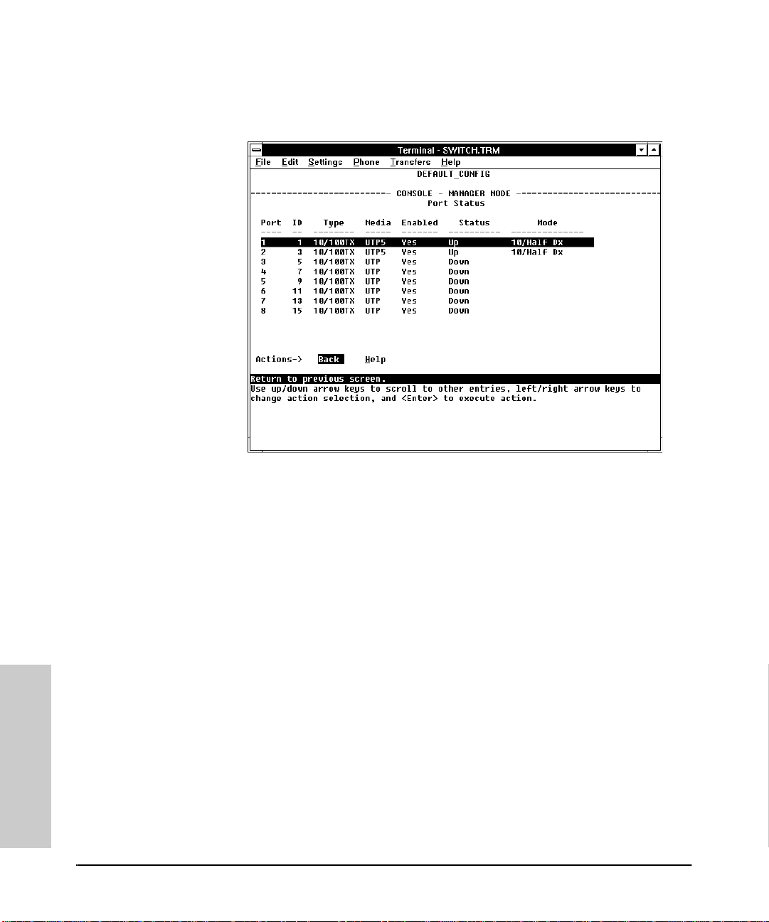
Monitoring and Analyzing Switch Operation from the Console
Status and Counters Menu
Port Status
Figure 4-3. Example of Port Status
For each port, this screen tells you the type of port and media, whether the
port is enabled and up or down, and the port’s operating mode. (Included is
the port ID number to use for SNMP MIB access.)
Monitoring and Analyzing
Switch Operation from the
4-4
Page 81
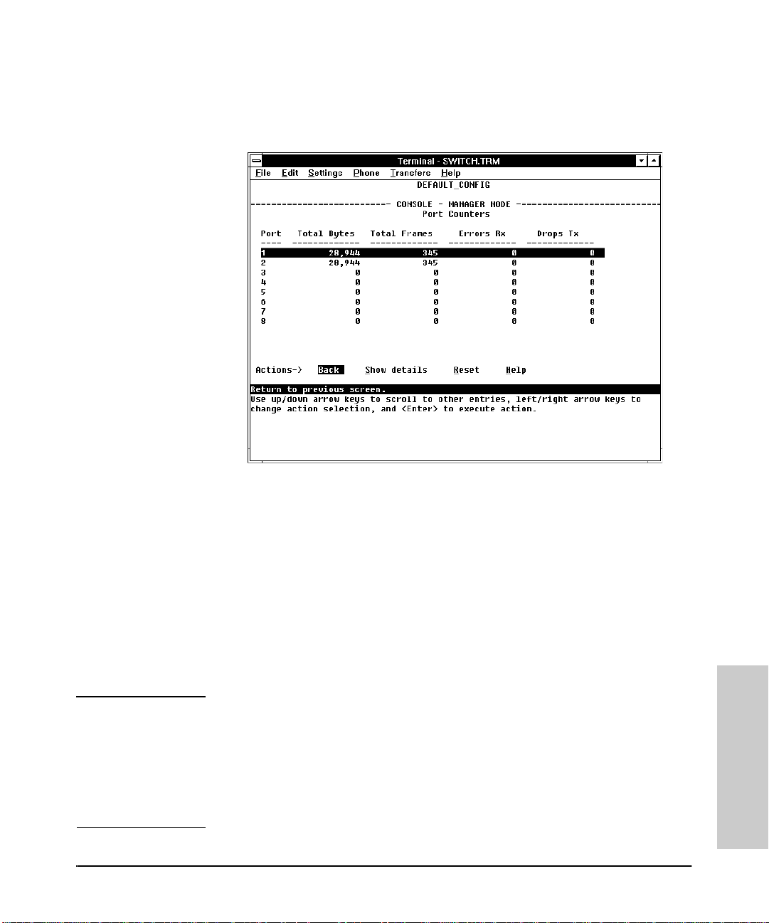
Port Counters
Monitor ing and Analyzing Switch Operation from the Console
Status and Co unters Menu
Figure 4-4. Example of Port Counters
This screen enables you to determine the traffic patterns for each port. Port
Counter features include:
■ Dynamic display of counters summarizing the traffic on each port since
the last reboot or reset
■ Option to reset the counters to zero (for the current console session). This
is useful for troubleshooting. Refer to the Note, below.
■ An option to display the link status, MAC address, and further port activity
details for a specific port ( Show details ).
Note The Reset action resets the counter display to zero for the current session,
but does not affect the cumulative va lues in the act ual hardware counter s. (In
compliance with the SNMP standard, the values in the hardware counters are
not reset to zero unless you reboot the switch.) Thus, using the Reset action
resets the displayed counters to zero for the current ses sion only. Exiting from
the console session and starting a new session restores the counter displays
to the accumulated values in the hardware counters.
4-5
Switch Operation from the
Monitoring and Analyzing
Page 82
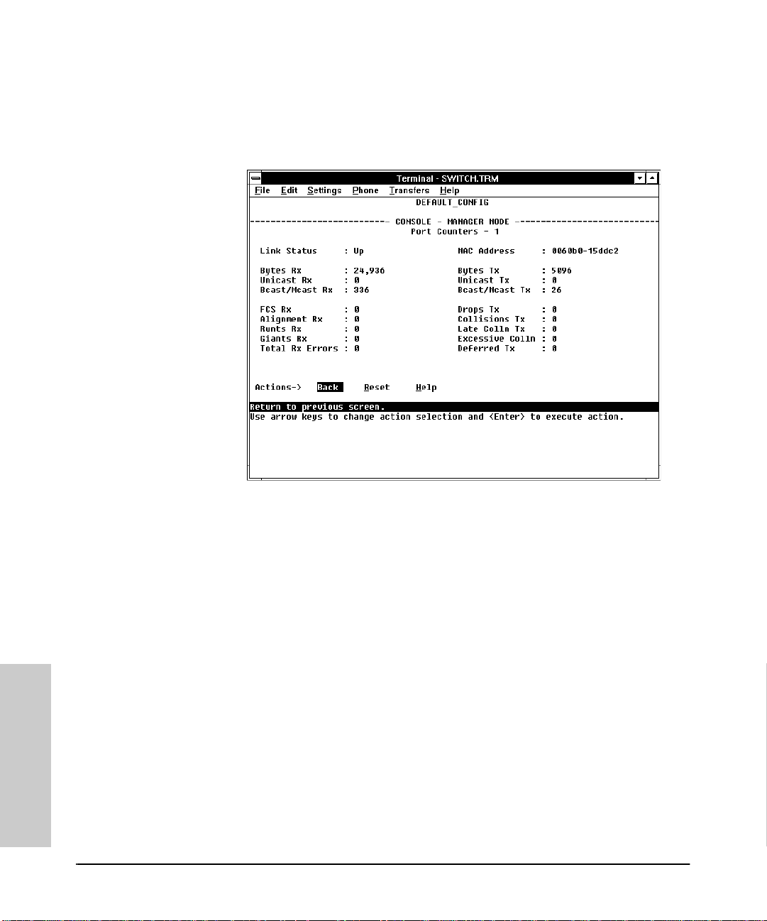
Monitoring and Analyzing Switch Operation from the Console
Status and Counters Menu
To view the elements that co mpr ise the traffic on a particular po rt, highlight
that port number (figure 4-4), then select Show details. For example,
selecting port 1 displays a screen similar to figure 4-5, below.
Figure 4-5. Example of the Display for Show details on a Selected Port
This screen also includes the Reset action. Refer to the note on page 4-5.
Monitoring and Analyzing
Switch Operation from the
4-6
Page 83
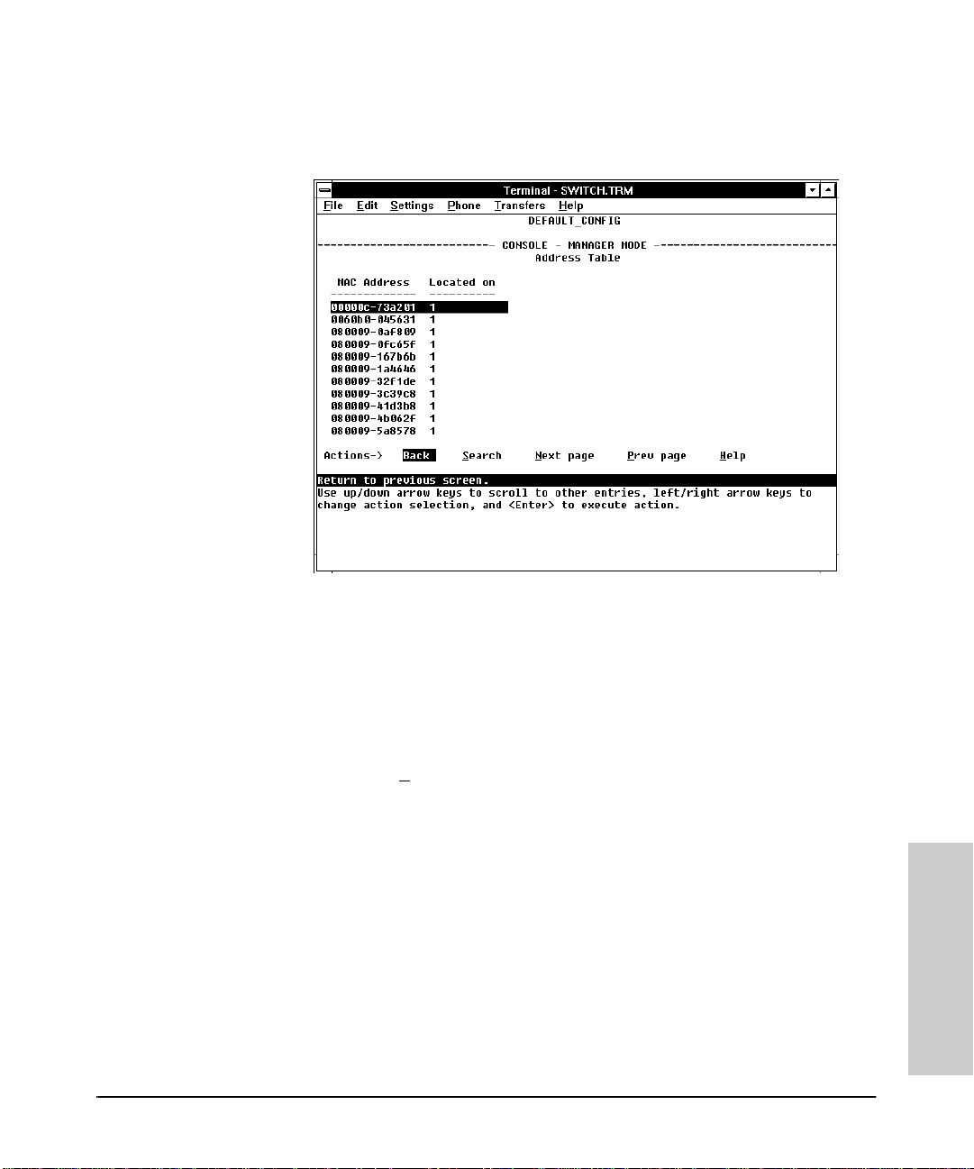
Address Tab le
Monitor ing and Analyzing Switch Operation from the Console
Status and Co unters Menu
Figure 4-6. Example of the Address Table
This screen lets yo u easily determine which switch port is being u sed to access
a specific device on the network. The listing includes:
■ The MAC addresses that the switch has learne d from network devices
attached to the switch
■ The port on which each MAC address was learned
You can use the S
earch action at th e bottom of the sc reen to locate a spec ific
device (MAC address).
4-7
Switch Operation from the
Monitoring and Analyzing
Page 84
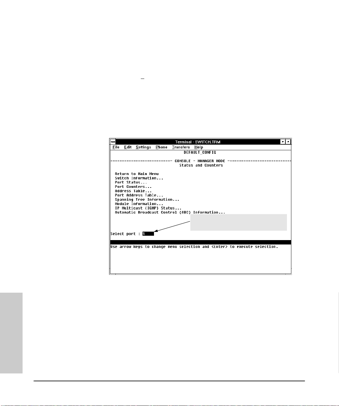
Monitoring and Analyzing Switch Operation from the Console
Status and Counters Menu
Port Address Table
This screen lets you easily determine which devices are attached to the
selected swi tch port by li stin g all o f the M AC addres ses d etected on that p ort.
You can use the S
earch action at the bottom of the screen to determine
whether a specific device (MAC address) is connected to the selected port.
To use the port address table:
1. Select Port Address Table from the menu in the Status and Counters
screen.
Use the Space bar to select the po rt for
which you wa nt t o di splay t he a ddre ss tabl e.
Figure 4-7. Example of How To Access the Port Address Table
2. When the Select Port prompt appears, press the Space bar to display
the port you want to examine, then press [Enter]. (See figure 4-7, above.)
Each port is identif ied by the sequen tial po rt numbers on the fro nt of the
switch.
Monitoring and Analyzing
Switch Operation from the
4-8
Page 85
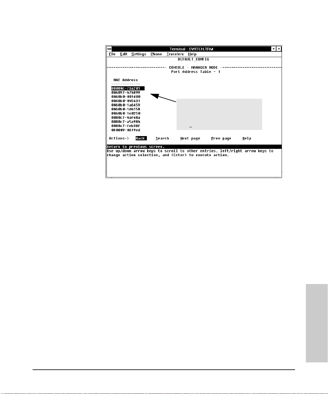
Monitor ing and Analyzing Switch Operation from the Console
Status and Co unters Menu
In this exampl e, seve ral MAC addres ses
accessed t hr ough port 1 appear in the
initial listing. To view any additional
addresses t ha t may be in t he li sting , u se
the N
ext page action.
Figure 4-8. Example of a Port Address Table for a Specific Port
Switch Operation from the
Monitoring and Analyzing
4-9
Page 86
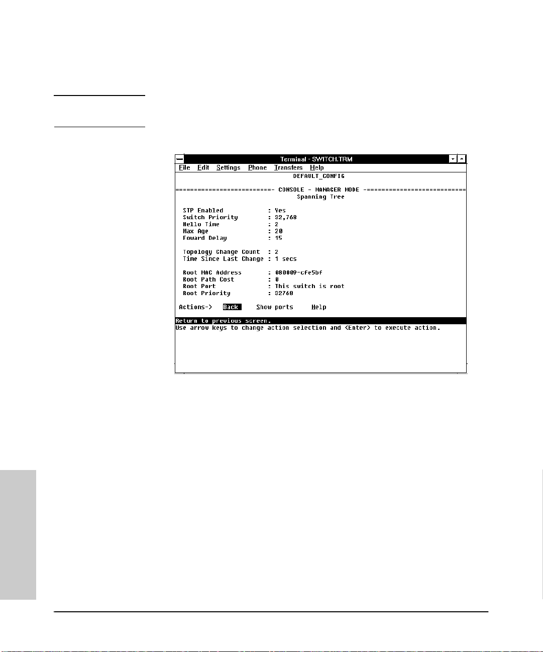
Monitoring and Analyzing Switch Operation from the Console
Status and Counters Menu
Spanning Tree (STP) Information
Note If multiple VLANs are configured on the switch, you will be prompted to select
a VLAN (by using the Space bar, then press ing [Enter]) to display this screen.
Figure 4-9. Example of Spanning Tree Information
Use this screen to determine current switc h-level STP parameter setting s and
statistics.
Monitoring and Analyzing
Switch Operation from the
4-10
Page 87
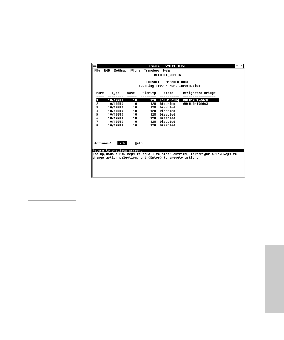
Monitor ing and Analyzing Switch Operation from the Console
Status and Co unters Menu
You can use the Show ports action at the bottom of the screen to display
port-level information and parameter settings for each port in the switch
(including port type, cost, priority, operating state, and designated bridge).
Figure 4-10. Example of STP Port Information
Caution Because incorrect STP settings can adversely affect network performance,
you should avoid making changes without having a strong understanding of
how STP operates. For more on STP, refer to “Spanning Tree Protocol (STP)”
on page 7-2.
4-11
Switch Operation from the
Monitoring and Analyzing
Page 88
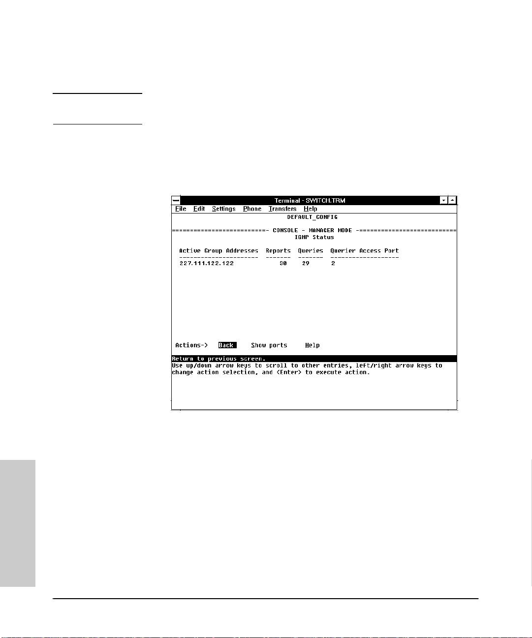
Monitoring and Analyzing Switch Operation from the Console
Status and Counters Menu
IP Multicast (IGMP) Status
Note If multiple VLANs are configured on the switch, you will be prompted to select
a VLAN (by using the Space bar, then press ing [Enter]) to display this screen.
This screen identifies the active IP multicas t groups the swit ch h as detected,
along with the number of report packets and quer y pa ck ets se en for each
group. It also indicates which port is used for connecting to the querier.
Figure 4-11. Example of IGMP Status Screen
Monitoring and Analyzing
Switch Operation from the
4-12
Page 89
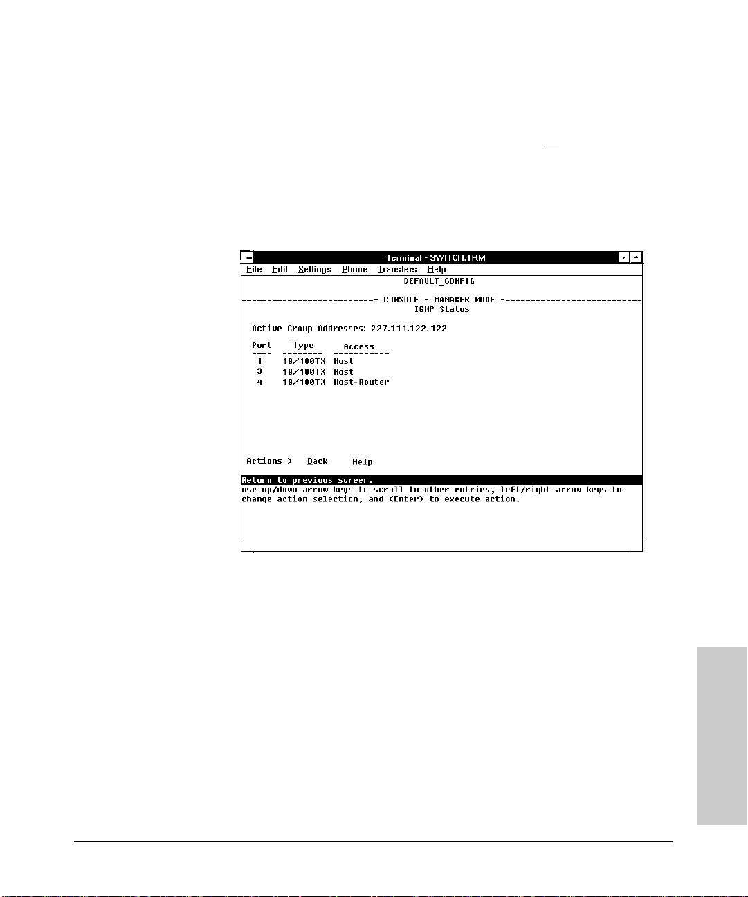
Monitor ing and Analyzing Switch Operation from the Console
Status and Co unters Menu
You can also display the port status of the individual multicast groups. (That
is, you can display the ports, port types, and whether the IGMP devices
connected to the switch via the port are hosts, routers, or both.) To do so,
select the group from the above screen and press [S] for
Show ports. For
example, suppose you wanted to view the status of the IP multicast group
227.111.122.122 shown in the above screen. You would highlight the row
beginning with that group number, then press [S]. You would then see a screen
similar to the following:
Figure 4-12. Example of an IGMP Status Screen for a Selected Multicast Group
4-13
Switch Operation from the
Monitoring and Analyzing
Page 90
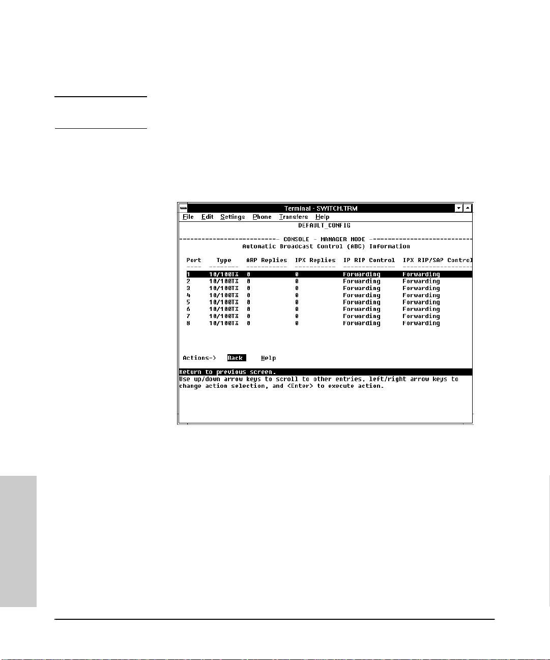
Monitoring and Analyzing Switch Operation from the Console
Status and Counters Menu
Automatic Broadcast Control (ABC) Information
Note If multiple VLANs are configured on the switch, you will be prompted to select
a VLAN (by using the Space bar, then press ing [Enter]) to display this screen.
This screen displays the number of IP ARP and IPX NSQ replies sent per port
and whether RIP and SAP packets are being forwarded or not forwarded per
port. If VLANs are configured, this data is on a per-VLAN basis.
Figure 4-13. Example of Automatic Broadcast Control (ABC) Screen
Monitoring and Analyzing
Switch Operation from the
4-14
Page 91

Monitor ing and Analyzing Switch Operation from the Console
Event Log
Event Log
The Event Log records operating events as single-line entries listed in chronological order. Each entry is composed of five fields:
Severity Date Time System Module Event Message
I 08/05/96 10:52:32 ports: port 1 enabled
Severity
Date
Time
System Module
generated the log entry. If VLANs are con f igu r ed , then a VLAN name also
appears for an event that is specific to an individual VLAN.
Event Message
is one of the following codes:
I (information) indicates routine events.
W (warning) indicates that a service has behaved unexpectedly.
C (critical) indicates that a severe switch error has occurred.
D ( d eb u g) reserved for HP internal diagnostic informati o n.
is the d a te in mm/dd/yy format that the entry was placed in the log.
is the time in hh:mm:ss format that the entry was placed in the log.
is the internal module (such as “ports” for port manager) that
is a brief description of the operating event.
Switch Operation from the
Monitoring and Analyzing
4-15
Page 92
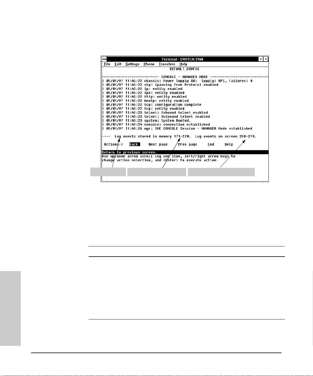
Monitoring and Analyzing Switch Operation from the Console
Event Log
Entering and Navigating in the Event Log Display. To enter the event
log, select Event Log from the Main menu.
Log Stat us Line
Range of Events in the Log Range of Log Events Displayed
Figure 4-14. Example of an Event Log Display
To display variou s portions of the Event Log, either precedi ng or fol lowing
the currently vi sible p ortion , use ei ther th e actio ns lis ted at t he bott om of the
display (Next page, Prev page, or End), or the keys described in the
following table:
Table 4-2. Event Log Control Keys
Key Action
[N] Advance the display by one page (next pa ge).
[P] Roll back the display by one page (previous page).
[v] Advance display by one event (down on e line).
[^] Roll back display by one event (up one line).
[E] Advance to the end of the log.
[H] Display Help for the event log.
Monitoring and Analyzing
Switch Operation from the
4-16
Page 93

Monitor ing and Analyzing Switch Operation from the Console
Event Log
The event log holds up to 100 lines in chronologica l o rder, from the oldest to
the newest. Each line consists of one complete event message. Onc e the log
has received 100 entries, it discards the current oldest line each time a new
line is received. The event log window contains 20 lines and can be positioned
to any location in the log.
The log status line at the bottom of the displ ay identifies where in the sequence
of event messages the displ ay is currently positioned.
The event log will be erased if any o f t he fol lowing occurs:
■ The switch is reset using the Reset button.
■ Powe r to the swit c h is in t errupt e d .
■ A new operating system is downloaded to the switch.
(The event log is not er ased by using th e Reboot Switch command in the
Main Menu.)
4-17
Switch Operation from the
Monitoring and Analyzing
Page 94

Page 95

5
Using SNMP To Monito r and
Using SNMP To Monito r and Manage the
Switch
You can manage the switch via SNMP from a network management station.
(The switch supports SNMP v1 and SNMP v2c, except as noted below for
SNMP v2 Notifications.) If you are using IP, you must either configure the
switch with the appropriate IP address or, if you are using Bootp to configure
the switch, ensure that the Bootp process provides the IP address. (The IPX
address is aut omatic ally co nfigur ed.) If mult iple V LANs are co nfigur ed, ea ch
VLAN interface shoul d have its own IP or IPX network address. This chapt er
provides an overvi ew of SNMP management for the switc h an d describes the
configuration process for the various features. For parameter-s p ecific information, refer to the Help provided in the individual configuration screens.
SNMP Man agement
SNMP management features on the switch include:
■ Security via configur ation of SNMP communities
■ Event reporting via SNMP traps and RMON (SNMP v2 Notifications are
not supported at this time.)
■ Managing the switch with a network management tool such as HP
AdvanceStack Ass istant
■ Monitoring data normally associated with the SNMP agent (“Get” opera-
tions). Supported Standard MIBs include:
• Bridge MIB (RFC 1493)
• Etherlike MIB (RFC 1650)
• Ethernet MAU MIB (RFC 1515)
• Interfaces Evolution MIB (RFC 1573)
• Novell Standard IPX MIB (ipx.mib)
• RMON MIB (RFC 1757)—etherstats, events, alarms, and hist o ry
• SNMP MIB-II (RFC 1213)
Manage the Switch
5-1
Page 96

Manage the Switch
Using SNMP To Monito r and
Using SNMP To Monitor and Manage the Switch
SNMP Management
HP Proprietary MIBs include:
• Statistics for message and packet buffers, tcp, teln et, and timep
(netswtst.mib)
• Port counters, forwarding table, and CPU statistics (stat.mib)
• tftp download (dow nld.mib )
• 802.12 (100VG) information (vg.mib)
• Integrated Communications Facility Authentication Manager and
SNMP communities (icf.mib)
• HP AdvanceStack Switch 800T configuration (config.mib)
• HP VLAN con figurati on informa tion (vlan.m ib) supporti ng
hpVlanGeneralGroup
• HP EASE MIB version 4 to allow EASE sampling
• HP Linktest MIB for basic device management (linktest.mib)
• HP ICF Linktest MIB for link test features (icfbasic.mib)
The switch SNMP agent also uses certa in variab les that ar e included in a
Hewlett-Packard proprietary MIB file you can add to the SNMP database
in your network management tool. You can copy the MIB file from the
compact disk (CD) shipped with the switch, or from following World Wide
Web site:
5-2
http://www.hp.com/go/network_city
For more information, refer to the card at the front of this manual.
Page 97

Using SNMP To Monitor and Manage the Switch
SNMP Configu ration Process
SNMP Configuration Process
The general steps to configu ri n g for SNMP access to the preceding features
are:
1. From the Main menu, select Configuration.
2. Enable and config ure an IP add ress for the switch, including any necessary gateways. An IPX addr ess is automatical ly configure d. (For more on
configuring IPX and IP, refer to page 3-7 and page 3-9.)
3. Configure the appropriate SNMP communities. (The “public” community
exists by default and is used by HP’s network management applicati ons.)
(For more on configuring SNMP communities, refer to page 3-13.)
4. Configure the appropriate trap receivers. (For more on configuring trap
receivers, r efer to page 3-15.)
In many networks, manager addresses are not used. In this case, all management stations usi ng the correct community name may ac cess this device with
the View and Acces s levels t hat have been set for that communi ty. If you want
to restrict access to one or more specific node s, you can enter up to 10 IP and/
or IPX addresses of such nodes into the Manager Address field. Configuring
one or more IP or IPX addresses in the Manager Address field means that
only the network management stations at those addresses are authorized to
use the community name to access the switch.
Using SNMP To Monito r and
Manage the Switch
Caution Deleting the community named “public” disables many network management
functions (such as auto-discovery, traffic monitoring, and threshold setting).
If security for network management is a concern, it is recommended that you
change the write access for the “publ ic” community to “Restricted”.
Note SNMP community and trap receive r configur ations are ac tivated w hen saved.
Rebooting the switch is not necessary u nless you have also configu red other
parameters that require rebooting in order to be activated. (For more on when
it is necessary to reboot, refer to “Rebooting the Switch” on page 2-10.)
5-3
Page 98

Page 99

Using the Advanced Commands
Overview
The Advanced Commands , which are accessed from the Main Menu, gives
you access to the following system mana gement comm an ds:
■ Help
■ Date
■ Time
■ History
■ Ping
■ IpxPing
■ LinkTest
■ Telnet
■ VLAN
■ ClearLED
■ Config
■ Delete
■ GetMIB
■ SetMIB
■ WalkMIB
■ Exit
■ Get/Put (TFTP)
■ ZGet/ZPut (ZMODEM)
■ Version
■ Log
■ !
■ Repeat
■ Page
■ Print
■ Redo
6
Using the Advanced
Commands
6-1
Page 100
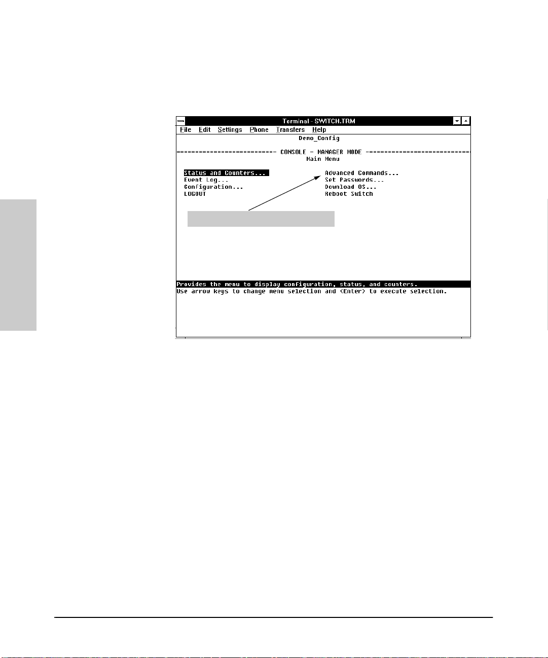
Using the Advanced Commands
Overview
How To Use the C ommand Promp t:
1. To access the command prompt, use the arrow keys to hi ghlight Advanced
Commands in the Main Menu and press [Enter].
Select t he Advanced Comman ds Prompt
Using the Advanced
Commands
Figure 6-1. Selecting the Command Prompt
2. Do the following:
• If there are no VLANs (virtual LANs) configured, go to step 3.
• If VLANs are configured, the prompt displays the name of the default,
or first VLAN, then asks you to select the VLAN in which to operate.
Use the Space bar to select the VLAN in which you want to operate,
then press [Enter].
3. The command prompt ap pears near the b ottom of the scre en. The te xt in
the prompt matches the System Name parameter. (If there are multiple
VLANs configured, then the text in the prompt matches the name of the
VLAN in which the command prompt is operating.) For example, in the
factory default configuration (no system name or VLANs configured), the
command prompt looks like this:
DEFAULT_CONFIG:
4. Type in the command you want to execute and pre ss [Enter]. For example,
to set the time to 9:55 a.m. you would execute the following co mman d:
6-2
DEFAULT_CONFIG: time 9:55 [Enter]
 Loading...