

Page 1

Installation and
Reference Guide
HP J3178A
HP AdvanceStack Switch 208/224 Management Module
Page 2

Page 3

HP AdvanceStack Switch 208/224
Management Module
Installation and Reference Guide
Page 4

© Copyright 1997 Hewlett-Packard Company
All Rights Reserved.
This document contains information which is protected by
copyright. Reproduction, adaptation, or translation without
prior permission is prohibited, except as allowed under the
copyright laws.
Publication N umber
5966-5228
Edition 1
March 19 9 7
Applicable Product
HP J3178A Switch 208/22 4 Management Module
Disclaimer
The information contained in this document is subject to
change with out notice .
HEWLETT-PACKARD COMPANY MAKES NO WARRANTY
OF ANY KIND WITH REGARD TO
THIS MATERIAL, INCLUDING, BUT NOT LIMITED TO,
THE IMPLIED WARRANTIES OF MER CHANT ABILITY
AND FITNESS FOR A PARTICULAR PURPOSE. HewlettPackard shall not be liable for errors contained herein or for
incidenta l o r co ns equent ial da mages in conn ect io n wit h th e
furnishing, performance, or use of this material.
Hewlett-Packard assumes no responsibility for the use or
reliability of its software on equipment that is not furnished
by Hewlett-P a ck a r d.
Warrant y
A copy of the specific warr anty terms applicable t o your
Hewlett- Packard products and replacement parts can be
obtained from your H P Sales and Service Office or
authorized dealer.
Hewlett-Packard Company
8000 Foothills Boulevard, m/s 5551
Roseville, California 95747-5551
http://www.hp.com/go/network_city
Page 5

HP Customer Support Services
How to get the latest software/agent firmware
You can download from the World Wide Web, HP FTP Library Service, CompuServe,
and HP BBS a compressed file (j3178xx.exe) containing the latest version of the HP
Switch 208/224 Management Module software and proprietary MIB. After you download the file, extract the file by typing
For example, j317801 [Enter].
World Wide Web
http://www.hp.com/go/network_city
Select the “Support” section.
From this web site, you can also download information on the HP networking prod-
ucts. If you have a growing network, download the Designing HP AdvanceStack
Workgroup Networks Guide or call 1-80 0-752-0900 in the U.S. to receive a copy through
the mail.
HP FTP Library Service
1. FTP to Internet IP Address — ftp ftp.hp.com.
2. Log in as anonymous and press [Return] at the passw or d pro m pt.
3. Enter bin to set the transfer type.
4. Enter cd /pub/networking/soft ware.
5. Enter get
filename
to transfer the file to your computer, then quit.
filename
and pressing [Enter].
CompuServe
1. Login to CompuServe.
2. Go to the “hp” service.
3. Select “HP Systems, Disks, Tapes, etc.”
4. Select “Networking Products” library.
5. Download
HP BBS
Set your modem to no par ity, eight bits, 1 st op bit, se t speed up to 14400 bps, and with
your telecommuni cation pr ogram (e. g. , Windows T ermina l) dial (208) 344 -1691 in the
U.S. to get the latest software for your HP networking product. For other countries,
see http://www.hp.com/cposupport/eschome.html.
(over for more services)
filename
and then quit.
✂
Obtain the latest console code (j3178xx.exe) from:
HP FTP Library: ftp ftp-boi.external.hp.com
World Wide Web: http://www.hp.c om /go/network_city
HP BBS: (208) 344-1691
(over)
Page 6

HP FIRST Fax Retrieval Service
HP FIRST is an automated fax retrieva l servi ce that is avail able 24 hours a day, seven
days a week. HP FIRST provides information on the following topics:
■ Product information
■ Troubleshooting instructions
■ Technical reviews and ar ticles
■ Configuration information
To access HP FIRST, dial one of the following phone numbers:
Location Phone Number
U.S. and Canada Only Dial 1 (80 0) 33 3-1 917 with your fax m achi ne o r to uch -tone phon e
Outside the U.S. and Canada Dial 1 (208) 344-4809 from your fax machine and press 9.
To re c eiv e a li st of c urr e nt ly a va il ab le do cu me nt s, e nt er do cu me nt n u mbe r 1 994 1. The i nf orm at i o n
you requested will be sent to you by return fax. For other countries, see http://www.hp.com/
cposupport/eschome.html.
and press 1.
Additional HP Support Services
In addition to the above services, you can purchase various HP telephone support
services which provide you expert HP technical assistance:
■ Network Phone-In Support provides you support at an hourly rate. In the U.S.,
call 1-800-790-5544. In other countries, please contact your local HP Response
Center to see if this service is available in your country.
■ HP SupportPack Comprehensive Network Support provides complete prob-
lem resolution for medium to large interconnected local and wide area
networks. Contact your HP Authorized Reseller or the nearest HP Sales and
Support Office for more information.
HP offers other hardware support services. Please contact your reseller for more
information.
CompuServe: Go hpsys
Network Phone-In
Support (hourly):
Lib 7.
Download j3178xx.exe
1-800-790-5544
✂
Page 7

Contents
1 Installin g th e Management Modu le
Included P a rts . . . . . . . . . . . . . . . . . . . . . . . . . . . . . . . . . . . . . . . . . . . . . . . . 1-2
Installa tion Steps . . . . . . . . . . . . . . . . . . . . . . . . . . . . . . . . . . . . . . . . . . . . . 1-2
Removing the Module . . . . . . . . . . . . . . . . . . . . . . . . . . . . . . . . . . . . . . . . . . 1-4
2 Management Module Description
Overview . . . . . . . . . . . . . . . . . . . . . . . . . . . . . . . . . . . . . . . . . . . . . . . . . . . . . 2-1
Module Features . . . . . . . . . . . . . . . . . . . . . . . . . . . . . . . . . . . . . . . . . . . . . . 2-3
3 The Switch Console
Overview . . . . . . . . . . . . . . . . . . . . . . . . . . . . . . . . . . . . . . . . . . . . . . . . . . . . . 3-1
Connecting a Console to the S witch . . . . . . . . . . . . . . . . . . . . . . . . . . . . 3-2
Modem Cable Pin-Out . . . . . . . . . . . . . . . . . . . . . . . . . . . . . . . . . . . . . . . . 3- 5
Starting and Ending a Console S ession . . . . . . . . . . . . . . . . . . . . . . . . . 3-6
Main Menu Features . . . . . . . . . . . . . . . . . . . . . . . . . . . . . . . . . . . . . . . . . . 3- 8
Screen Structur e and Navigation . . . . . . . . . . . . . . . . . . . . . . . . . . . . . . . 3-9
Using Password Secu ri ty . . . . . . . . . . . . . . . . . . . . . . . . . . . . . . . . . . . . . . 3-11
Rebooting the Switch . . . . . . . . . . . . . . . . . . . . . . . . . . . . . . . . . . . . . . . . . 3-15
Advanced Commands . . . . . . . . . . . . . . . . . . . . . . . . . . . . . . . . . . . . . . . . . 3-17
4 Configuring the Switch From the Console
Overview . . . . . . . . . . . . . . . . . . . . . . . . . . . . . . . . . . . . . . . . . . . . . . . . . . . . . 4- 1
Configurable Features . . . . . . . . . . . . . . . . . . . . . . . . . . . . . . . . . . . . . . . . . 4- 3
System Configuration . . . . . . . . . . . . . . . . . . . . . . . . . . . . . . . . . . . . . . . . 4-4
Port Configuration . . . . . . . . . . . . . . . . . . . . . . . . . . . . . . . . . . . . . . . . . . 4-5
IPX Service . . . . . . . . . . . . . . . . . . . . . . . . . . . . . . . . . . . . . . . . . . . . . . . . . 4- 6
Internet (IP) Service . . . . . . . . . . . . . . . . . . . . . . . . . . . . . . . . . . . . . . . . . 4-8
Using Bootp . . . . . . . . . . . . . . . . . . . . . . . . . . . . . . . . . . . . . . . . . . . . . . . . 4- 9
v
Page 8

SNMP Communities
Trap Receivers . . . . . . . . . . . . . . . . . . . . . . . . . . . . . . . . . . . . . . . . . . . . . 4-14
Serial Link Configuration . . . . . . . . . . . . . . . . . . . . . . . . . . . . . . . . . . . . 4-15
Console Configuration . . . . . . . . . . . . . . . . . . . . . . . . . . . . . . . . . . . . . . 4-16
Spanning Tree Configuration . . . . . . . . . . . . . . . . . . . . . . . . . . . . . . . . . 4-17
Network Monitoring Port . . . . . . . . . . . . . . . . . . . . . . . . . . . . . . . . . . . . 4-19
Saving Confi gurations . . . . . . . . . . . . . . . . . . . . . . . . . . . . . . . . . . . . . . . . 4-21
. . . . . . . . . . . . . . . . . . . . . . . . . . . . . . . . . . . . . . . . 4-12
5 Monitorin g Switch Operation Fro m the Console
Overview . . . . . . . . . . . . . . . . . . . . . . . . . . . . . . . . . . . . . . . . . . . . . . . . . . . . . 5-1
Status and Counters Menu . . . . . . . . . . . . . . . . . . . . . . . . . . . . . . . . . . . . . 5-2
Switch Information . . . . . . . . . . . . . . . . . . . . . . . . . . . . . . . . . . . . . . . . . . 5-3
Port Status . . . . . . . . . . . . . . . . . . . . . . . . . . . . . . . . . . . . . . . . . . . . . . . . . 5-4
Port Counters . . . . . . . . . . . . . . . . . . . . . . . . . . . . . . . . . . . . . . . . . . . . . . . 5-5
Port Counters - Show Details . . . . . . . . . . . . . . . . . . . . . . . . . . . . . . . . . . 5- 6
Address Table . . . . . . . . . . . . . . . . . . . . . . . . . . . . . . . . . . . . . . . . . . . . . . 5-7
Port Address Table . . . . . . . . . . . . . . . . . . . . . . . . . . . . . . . . . . . . . . . . . . 5-8
Spanning Tree (STP) Information . . . . . . . . . . . . . . . . . . . . . . . . . . . . . 5-10
Event Log . . . . . . . . . . . . . . . . . . . . . . . . . . . . . . . . . . . . . . . . . . . . . . . . . . . . 5-12
6 Using SNMP To Monitor and Manage the Switch
Overview . . . . . . . . . . . . . . . . . . . . . . . . . . . . . . . . . . . . . . . . . . . . . . . . . . . . . 6-1
SNMP Management F eatures . . . . . . . . . . . . . . . . . . . . . . . . . . . . . . . . . . 6- 2
SNMP Co nfi guration P rocess . . . . . . . . . . . . . . . . . . . . . . . . . . . . . . . . . . 6-3
Advanced Management: RMON and EASE Support . . . . . . . . . . . . . . 6-4
RMON . . . . . . . . . . . . . . . . . . . . . . . . . . . . . . . . . . . . . . . . . . . . . . . . . . . . . 6-4
EASE . . . . . . . . . . . . . . . . . . . . . . . . . . . . . . . . . . . . . . . . . . . . . . . . . . . . . . 6-4
7 Troubleshooting
Checking the Module LEDs . . . . . . . . . . . . . . . . . . . . . . . . . . . . . . . . . . . . 7-2
Problem/Solution Table . . . . . . . . . . . . . . . . . . . . . . . . . . . . . . . . . . . . . . . . 7-3
IP Config uration Errors . . . . . . . . . . . . . . . . . . . . . . . . . . . . . . . . . . . . . . . 7-4
Diagnostic Tests . . . . . . . . . . . . . . . . . . . . . . . . . . . . . . . . . . . . . . . . . . . . . . 7-4
vi
Page 9

Testing the Switch and Management Module
Testing the Switch’s Ports and the Links . . . . . . . . . . . . . . . . . . . . . . . . 7-5
Resetting the Switch . . . . . . . . . . . . . . . . . . . . . . . . . . . . . . . . . . . . . . . . . . 7-7
Clearing Passwords on the Switch Console . . . . . . . . . . . . . . . . . . . . . 7-8
HP Customer Support Services . . . . . . . . . . . . . . . . . . . . . . . . . . . . . . . . . 7-9
. . . . . . . . . . . . . . . . . . . . 7-4
A Specificati o ns
Regulatory Statem en ts . . . . . . . . . . . . . . . . . . . . . . . . . . . . . . . . . . . . . . A-3
B Modem Configuration
C File Transfers
Overview . . . . . . . . . . . . . . . . . . . . . . . . . . . . . . . . . . . . . . . . . . . . . . . . . . . . C-1
Downloading an Operating System . . . . . . . . . . . . . . . . . . . . . . . . . . . . C- 1
Using TFTP To Downloa d the OS File . . . . . . . . . . . . . . . . . . . . . . . . . C-2
Using the SNMP-Based HP Download Manager . . . . . . . . . . . . . . . . . C-4
Using the Switch -t o -S witch Download . . . . . . . . . . . . . . . . . . . . . . . . . C-4
Using the Zmodem to Download the OS File . . . . . . . . . . . . . . . . . . . C-5
Troubleshooting TFTP Downloads . . . . . . . . . . . . . . . . . . . . . . . . . . . . C- 6
Transferring Switch Configurations . . . . . . . . . . . . . . . . . . . . . . . . . . . C-8
D Spanning T r ee O per a t ion
Spanning Tree Protoc ol (STP) . . . . . . . . . . . . . . . . . . . . . . . . . . . . . . . . D-1
vii
Page 10

viii
Page 11
Installing the Management Module
Installing the Mana gement Module
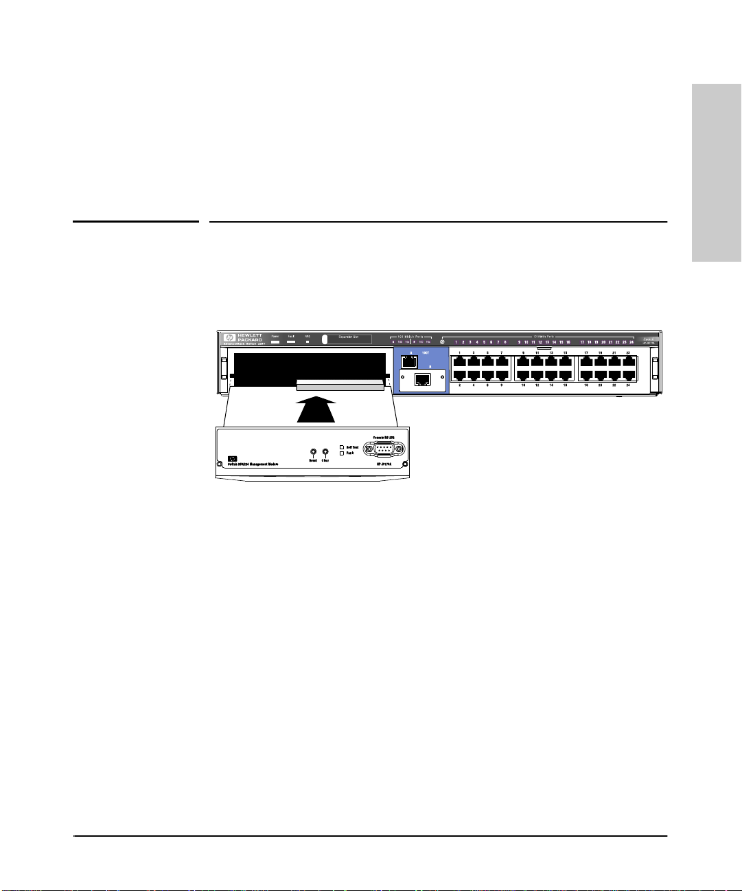
The HP J3178A Adva nceStack Switch 208/22 4 Management Module is inst alled
into the front of the HP AdvanceStack Switch 208T or 224T.
In this manual, this module will be called the Switch Management Module.
Active
Base MAC Address
Switch Management Module
1
Installing the Management
Module
Figure 1-1. The Switch 208/224 Management Module
When installed, the Switch Management Module adds these features to your
switch:
■ Access to the swit ch console fro m which you can configure, monitor, and
troubleshoot the switch
■ Access to the switch from SNMP network management programs, such
as HP AdvanceStack Assi stant, for controlling th e swit ch usin g an
advanced, graphics-based interface
■ Configurable full-duplex port operation
■ Configurable support for the Spanning Tree Protocol for switched
networks
■ Configurable MAC Address Table aging
This chapter shows you how to install your Switch Management Module.
1-1
Page 12

Installing the Management
Installing the Management Module
Included Parts
Included Parts
Verify that these parts were included with the product:
Module
• Switch 208/224 Management Module
• HP AdvanceStack Switch 208/224 Management Module
Installation and Reference Guide (5966-5228), this manual
• Console cable (5182-479 4)
• HP AdvanceStack Assistant for Windows CD kit
• HP AdvanceStack Products CD kit
Installation Steps
Caution Anti-Static Precautions:
Static electrici ty can severel y damage the s ensitive electr onic components on
the module. When installing the module in your switch, follow these procedures to avoid damage from static electricity:
■ Handle the module by its edges and avoid touching the components and
the circuitry on the board.
■ Equalize any static ch arge difference betw een your body and the switch
by wearing a wrist static-protector strap and at tach in g it to the switch's
metal body, or by frequently touching the switch's metal body while you
are installing the module.
1-2
1. Before installing the Switch Management Module, unplug your switch
from the power source. This protects the module and switch from potential electrical damage.
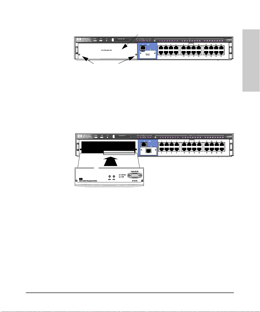
2. Unscrew the two captured screws holding the cover plate to the switch's
Management Slot and r emove the cover , as shown i n fi gure 1-2. Note t hat
the screws will release outward when unscrewed far enough. Do not
unscrew them completely from the cover pl ate.
Page 13
Installing the Management Module
Installation Steps
cover plate
Loosen these
screws
Figure 1-2. Remove the cover plate
3. Insert the Management Module into the switch. Line up the sides of the
module with the rails on the sides of the swit ch ’s slot, then push the
module into the slot until it is firmly seated in the connector in the back
of the slot.
Installing the Management
Module
Switch Management Module
Figure 1-3. Insert the Switch Management Module
4. Tighten the two screws that hold the module in place. Be careful not to
overtighten the screws.
1-3
Page 14

Installing the Management Module
Removing the Module
5. Turn on the power to the switch by plugging in the power cord. During
power-on, the following occurs:
Installing the Management
At Power On The swit ch begi ns i ts powe r-o n self test foll owe d by t he m odule ’s self
Module
During Self Test All Swit ch and Mo dul e LEDs a re on f or ap proxi matel y 5 se conds, then
After Self Test The switch Fa ult LED a nd the mo dule LEDs (Self Test and Fault ) turn of f.
test. Ports are temporarily disab led until the Switch Manage m ent
Module configures the ports.
just the switch Power and Fault LEDs and the Management Module
Self Test and Fault LEDs are on for the remainder of the sel f t est. The
switch and m odule self tests require appr oximately 15 sec onds total.
If the module Fault LED stays on or flashes, refer to chapter 7, “Troubleshooting” in this guide.
You have now completed installation and verification of the module.
To configure IP/IPXcommunication for the Switch Management Module, see
chapter 4, “Configuring the Switch From the Console”.
Removing the Module
The module is removed from the switch by reversing the installation steps
described earlier in this document. When handling the module, be sure to
follow the anti-static p recautions described on page 1-2.
To remove the module, follow these steps:
1. Remove power from the switch by unpluggi ng the power cord.
2. Unscrew the two captured screws holding the modul e in t he switch .
3. Pull the module out of the slot.
4. Replace the Management S lot co ver plate.
Caution Replace the cover pla te over the slot using the two screws th at hold it in place.
Be careful not to overtighten the screws. When using the switch, the cover
plate must always be ins talled. This is requ ired for safety and to ens ure proper
switch cooling.
1-4
Page 15
Management Module Description
Overview
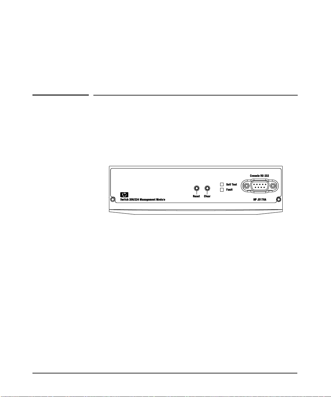
The HP AdvanceStack Switch 2 08/2 24 Management Module is ins talled i n the
Management Slot in the front of either the HP Switch 208T or HP Switch 224T.
The Switch Management Module has the physical el ements shown in the figure
below.
2
■ Reset Button - used to reboot the Management Module and the
switch in which it is installed. This cl ears any tempor ary error conditions that may have occurred, executes the module and switch self
tests, and returns all network activity counters to zero. The counters
are displayed in the switch co n sole interface and through network
management applications.
■ Clear Button - used for these purposes:
• When pressed by itself for at least one second, deletes any switch
console access password s that you may have configured. Use this
feature if you have misplaced the password and need console
access.
This but t on is provided for your convenience, but i t s presence
means tha t if you are conce rned wi th the se curit y of the switch
configuration and operation, you should make sure the switch
with the mana gement module is ins talle d in a se cure loc ation,
such as a lo ck ed wiring closet.
2-1
Page 16

Management Module Description
Overview
Description
• When pressed with the Reset button in a specific pattern, clears
any configuration changes you may have made through the
switch console and SNMP management, and restor es the factory
default configuration to the switch and the module. See “Restoring the Factory Default Configuration” in chapter 7, “ Troubleshooting” for the specific method to restore the factory default
configuration.
■ Self Test LED - When lit, indicates that the Management Module or
the switch in which the module is installed is undergoing its self test,
which occurs every tim e the switch is plugged into a power source,
or as a result of pressi ng the Reset button on the Management Module,
or from rebooting or resetting the switch from the switch console or
from network management.
■ Fault LED - When lit with the Self Test LED, indicates that the
Management Modul e is executing its s e lf test. The self test normally
takes approximately 10 seconds. If the Self Test and Fault LEDs stay
on for longer than this, or if the Fault LED is flashing at an y time, an
error has occurred on the module. See chapter 7, “Troubleshooting”
for more information on the LED and error recovery procedures.
Management Module
■ Console RS-232 Port - This port is used to connect a console to the
switch, either directly using the serial cable supplied with the
Management Module, or through a modem connection. These connections are described in chapter 3, “The Switch Console”. The console
can be either a PC running a VT-100 terminal emulator, or a VT-100
termi n a l it self.
■ MAC Address - Thi s is the unique hardware identity of the manag e-
ment module. It is also used to identify the switch into which the
module is installed, and can be used in network connectivity tests
between the switch and other network devices. In an IPX network,
this address is also used as the Node Address part of the IPX network
address.
2-2
Page 17

Management M odule Descript ion
Module Features
Module Feat ure s
When you install the Switch 208/224 Managem ent Module in your Switch 208T
or 224T, you get these enhanced sw itch cap ab ilities:
■ Full-duplex port operation. By default, the 10 Mbit/s and
100 Mbit/s ports on the S wi tch 208/224 operate in half-duplex mode.
With the Switch Management Module insta lled, these ports can be
configured to operate in full-duplex mode.
■ Address Aging. The Switch 208/224 au to mati cally learns the MAC
address of the devices connected to its ports and stores those addresses in an 8000-entry address table. When a device is moved, it s new
location is automatically learned and kept in the table so proper
communication is maintained with the device. With the Management
Module installed, the additional benefit is that inacti ve addresses are
aged out of the table -- the table is kept up to date with the addresses
of active nodes only.
■ Spanning Tree Support. The Switch 208/224 uses th e IEEE 802.1d
Spanning Tree Protocol (STP) to ensure that only one path at a time
is active between any two nodes in the network, thus preventing loops
that cause broadcast storms from occurring in the network topology.
Management Module
Description
By default, STP is disabled on the switch. You can use the switch console
to enable STP operati on; see chapter 4, “Config uring the Switch F rom the
Console” for those configuration procedures. For more information on
how STP works, see appendix D, “Spanning Tree Operation”.
■ Switch Console. The Management Module has an RS-232 port to
which you can connect a console that can be used to configur e,
monitor, and troubleshoot the switch and its ports. The console
interface can be used “out-of-band” from a PC or terminal directly
connected to the port or remotely through a modem connection, or
“in-band” through a Telnet session. For more information on the
switch consol e, see the se ction “Switch Co nsole Featur es” in chap ter
3, “The Switch Cons ol e”.
■ Networ k Management. The Management Module has firmware
agents on board that provid e SNMP Network Management control of
the switch, support for RMON (four groups) and HP Embedded
Advanced Sampling Environment (EASE) agen ts to diagnose network problems to help optimize network performance. For more
information t he n etw ork management feature s pr o vid ed by the Management Module and how to configure those features, see chapter 6,
“Using SNMP to Monitor and Manage the Switch”.
2-3
Page 18

Page 19

The Switch Console
Overview
About the Console Inter face. The console in terface enab les you to reco nfigure the switch and to monitor the switch status and performance. It consists of a series of management screens accessed through a menu-driven screen structure that begin s at the Main Menu.
The switch console in terface enables you to use a PC or a terminal to do the
following:
■ Modify the switch’s configuration, or provide configuration for Telnet or
network management acc ess from an SNMP-based manage ment program
such as Hewlett-Packard’s AdvanceStack Assistant (ASA)
■ Monitor the switch and port status and network activity counters
■ Control console security by configuring passwords
■ Use the switch’s event log and some advanced commands to help in
troubleshooting
■ Download new software
3
The Switch Console
Note The Switch 208/224 and its Management Module are shipped with a factory
default configuration that enables operation as a multiport learning bridge
when installed in a network. All ports are enabled, Spanning Tree Protocol
support is disabl ed, and SNMP network management i s enabled over IP X and
IP (by way of Bootp). For this operation, co nnec tin g a co nso le device is
unnecessary. How ever, for s ome of the o ther u ses listed a bove , yo u will need
to use the switch console.
This chapter descri b es the fo llowing features:
■ Connecting a console to the switch (page 3-2)
■ Starting and ending a console session (page 3-6)
■ The Main Menu Features (page 3-8)
■ Screen structure and nav igation (page 3-9)
■ Using password security (page 3-11)
■ Rebooting the switch (page 3-15)
3-1
Page 20

The Switch Console
Connecti ng a Console to the Switch
Connecting a Console to the Sw it ch
The Switch 208/224 Management Module offe rs t wo methods of acc ess to the
console interface:
■ Out-of-band console access:
• Directly connected to the Console RS-232 port, using a serial cable
• Remotely connected to the Console RS-232 port, using modems an d
■ In-Band access using Telnet from a PC or UNIX station on the network,
and a VT-100 terminal emulator. This method requires that you first
configure an IP address and subnet mask by using either out-of-band
console access or Bootp. The Management Module allows one outbound
and one inbound Telnet session to be running simultaneously. It can also
simultaneously support one console session through the Console RS-232
port and one Telnet console session.
and a PC running a VT-100 termina l emulator or an actual VT-100
terminal
a PC running a terminal emulator or an actual terminal
You can put sec urity restrictions o n console access by setting Manager-level
and Operator-level passwords. See “Using Password Security” later in this
chapter.
Default Serial Communication Settings
The default communication settings on the Switch Management Module are:
• 9600 baud
The Switch Console
• 8 data bits
• 1 stop bit
• XON/XOFF
• For Windows Terminal program, also disable (uncheck) the “Use
Function, Arrow, and Ctrl
Configure your PC or terminal to operate with these settings. If you want to
operate the terminal using a different configuration, make sure you change
with settings on both the terminal an d on the switch . Chan ge th e switch
settings first, then change the terminal settings, and reestablish the console
session.
Keys for Windows” option.
3-2
Page 21
Connecting a Console to the Switch
The Switch Console
Direct Console Connection, Using A Serial Cable and a PC
Terminal Emulator or Terminal
You can use either a PC emulating a VT-100 terminal (such as the terminal
application included with Microsoft Windows 3.1) or a VT-100 terminal.
To directly connect a PC or terminal to a Managem en t Modul e, follow these
steps:
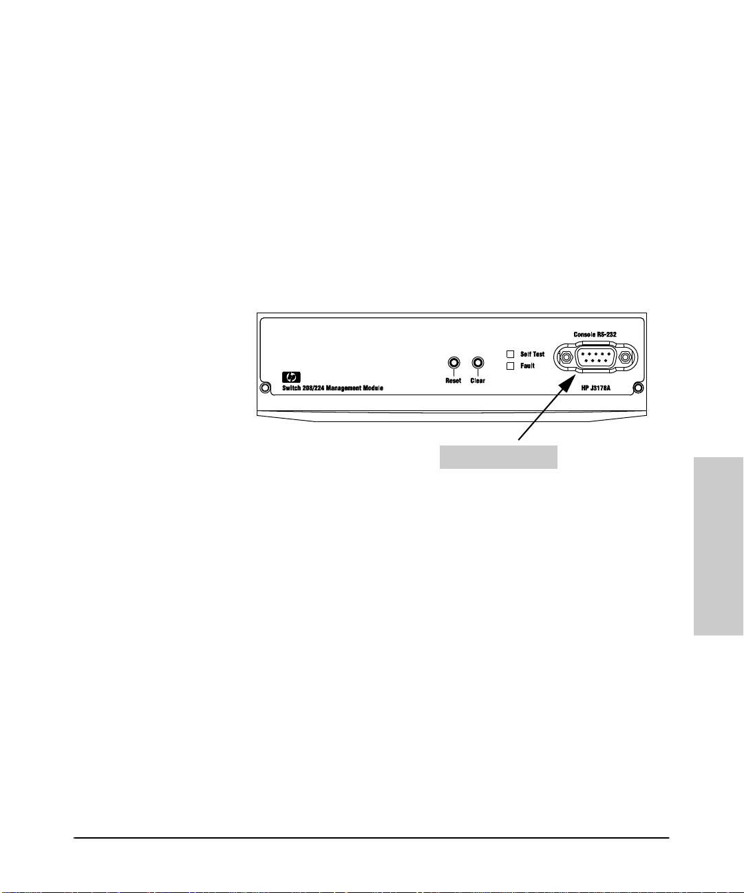
1. Connect the PC or terminal to the switch’s Console RS-232 port, on the
Management Module, using an RS-232 -C console cable (included wit h the
Management Module). (If your PC or terminal has a 25-pin connector, first
attach a 9-pin to 25-pin “straight-through” adapter at one end of the
console cable.)
Console RS-2 3 2 Po r t
Figure 3-1. Connecting a PC or Terminal to the Console RS- 232 Port
2. Turn on the terminal or PC’s power (and, if using a PC, start th e PC
terminal emulation program).
3. When you see this message:
Waiting for speed sense. Press enter to continue.
Press [Enter]. You wil l then see the switch con sole Main Menu. See “ Starting
and Ending a Console Sess ion” on page 3-6.
4. If you want to continue with console managem en t of the switch at this
time, refer to the rest of this chapter f or gener al console procedures, to
chapter 4, “Configurin g the S wi t ch From the Co n sole”, and to chapter 5,
“Monitoring Switch Operation From the Console”.
The Switch Console
3-3
Page 22
The Switch Console
Connecti ng a Console to the Switch
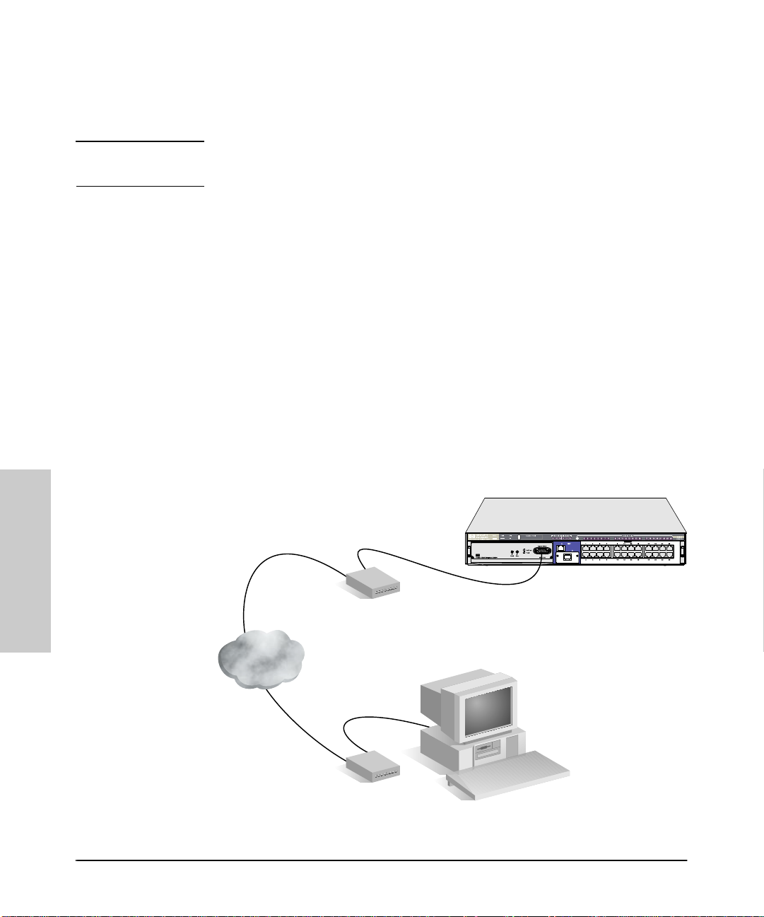
Remote Console Connection Using a Modem and a PC
Terminal Emulator or Terminal
Note For remote console management, use a pair of full-duplex, asynchronous
(character-mode) modem s as shown in figure 3-2.
1. Before installing the modems, make sure they are both correctly initial-
ized. Refer to appendix B, “Modem Configuration” for the correct initialization strings.
2. At the site where the Switch 208/224 is installed:
a. Connect the modem to the Switch Management Module’s consol e port
using a standard “straight-through” RS-232-C modem cable. (For
modem cable pin-outs, refer to “Modem Cable Pin-Out” on next page.)
b. If necessary, co nfigure t he PC or terminal to operate with the c urrent
serial link configuration of the Switch Management Module.
3. At the site where the console is to be located, conn ect th e PC emul ating
a terminal, or a term inal to the modem using a stand ard RS-232-C mod em
cable. Make s ure the t erminal and modems are fu nctioning proper ly, then
establish the link between the terminal’s modem and the switch’s modem
according to the modem instructions.
“straight-through”
RJ-11 telephone
cable
The Switch Console
“straight-through”
modem cable
RJ-11 telephone
cable
Exter nal modem
(You can al so use an internal modem.)
modem cable
Switch with
Management Module
External modem
PC running
a VT-100 terminal program
or a VT-100 terminal
Figure 3-2. Example of Remote Access through a Modem Connection
3-4
Page 23

Connecting a Console to the Switch
The Switch Console
4. When you see this message:
Waiting for speed sense. Press enter to continue.
Press [Enter]. You wil l then see the switch con sole Main Menu. See “ Starting
and Ending a Console Sess ion” on page 3-6.
5. If you want to continue with console managem en t of the switch at this
time, refer to the rest of this chapter f or gener al console procedures, to
chapter 4, “Configurin g the S wi t ch From the Co n sole”, and to chapter 5,
“Monitoring Switch Operation From the Console”.
Modem Cable Pin-Out
Modem end
25-pin male
23Tx
32Rx
47RTS
58CTS
66DSR
75GND
81CD OR DCD
20 4 DTR
22 9 RI
23 DRS –typically on V.24 (European) modems
Switch end
9-pin male Signal
(not connected)
The Switch Console
3-5
Page 24

The Switch Console
Starting and Ending a Console Session
Starting and Ending a Console Session
Note This section assumes that you have already configure d and co nnected a
terminal device to your switch (as described earlier in this chapte r) o r that
you have already enabled Telnet access to the switch. (To enabl e Telnet
access, refer to “Cons ol e Co n f igu ration” on page 4-16.)
How To Start a Console Session:
1. Start your PC terminal emulator, terminal, or Telnet session on a remote
terminal device.
2. Do one of the following:
• If you are using Telnet, go to the next step.
• If you are using a PC terminal emulator or a terminal, you should then
see the following prom pt:
Waiting for speed sense. Press <Enter> to continue.
Note: If the console displays a series of random and/or unread-
able characters instead of the above prompt, the Baud Rate
setting for the terminal may be different from that of the console
interface. The switch’s autosensing feature remedies this prob-
lem when you press any key. You may have to press the key a
few times.
Press [Enter] and go to the next step.
3. A message indicatin g the baud rate at which the serial inter face (Console
The Switch Console
3-6
RS-232 port) is operatin g is br iefly displayed, followed by the copyright
screen. Do one of the following:
• If a password has been set, the Password prompt appears. Type the
password and press [Enter] to display the Main Menu (figure 3-3).
• If no password has been set, you will see this prompt:
Press any key to continue.
Press [Enter] to display the Main Menu (figur e 3-3).
If there is any system-down information to report, the switch displays it
in this step and in the Event Log.
Page 25
Starting and Ending a Cons ole Session
The Switch Console
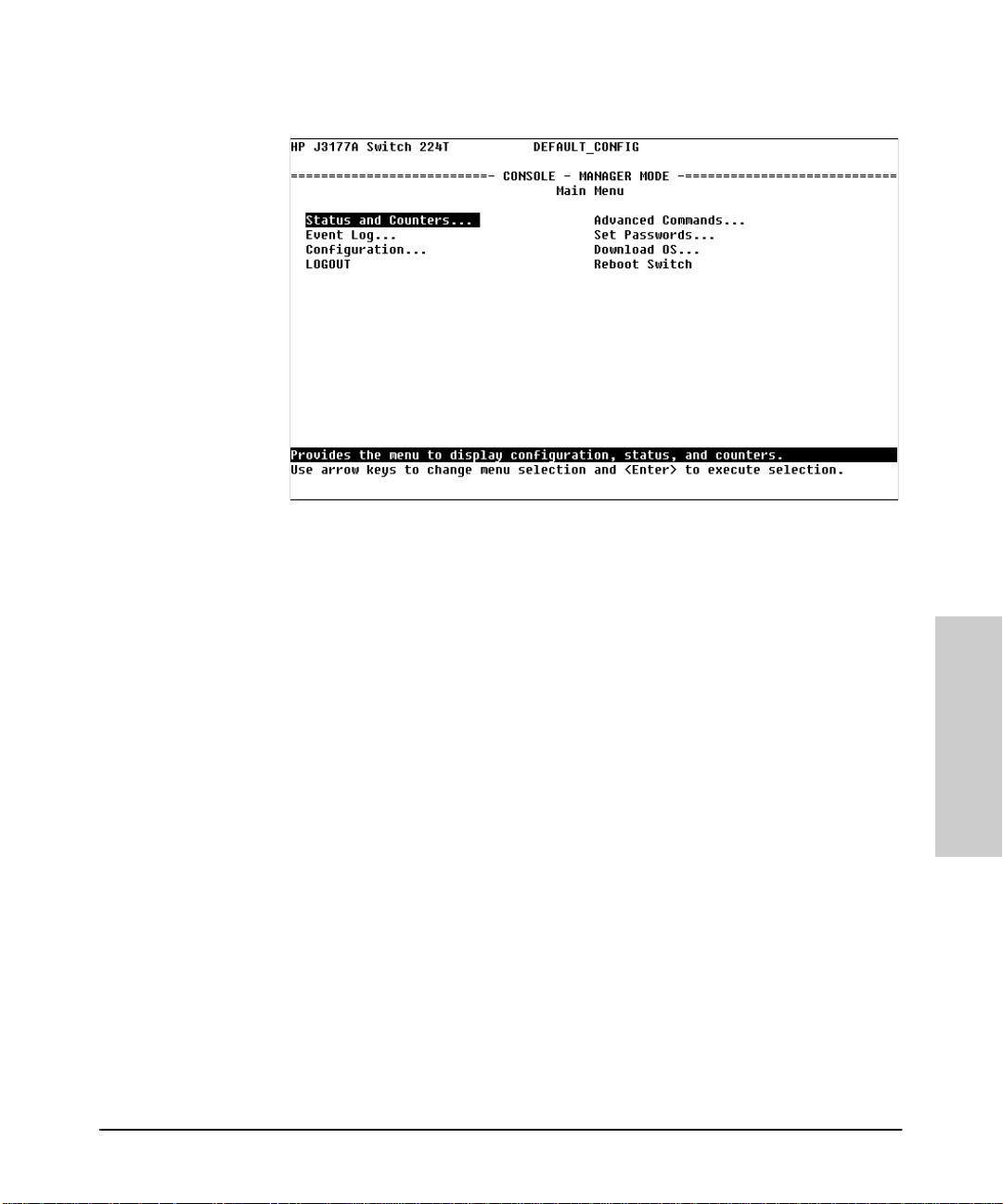
Figure 3-3. The Main Menu
For a description of Main Menu features, refer to “Main Menu Features” on
page 3-8.
How To End a Cons ole Session:.
1. If you have not made configuration changes in the current session, return
to the Main Menu, highlight LOGOUT , and press [Enter].
2. Configuration changes requiring a reboot of the switch are indicated by
an asterisk (*) next to the configured item in the Configuration menu. (See
“Rebooting To Activate Configuration Changes” on page 3-16 .) If you have
made configuration ch an ges that require a reboot of the switch in ord er
to take effect:
a. Return to the Main Menu.
b. Us e the arrow keys ( [<] , [>] , [v] , and [^] ) to highlight Reboot Switch
in the Main Menu and press [Enter] to reboot.
c. When the reboot completes, the switch automatically reestablishes
the console connection, and you can restart your console session, as
described on the previous page. Or, if you have finished using th e
console, you can cl ose the terminal emula tion program before res tarting the console session.
3-7
The Switch Console
Page 26

The Switch Console
The Switch Console
Main Menu Features
Main Menu Features
The Main Menu (figure 3-3 on page 3-7) gives you access to these console
interface features:
• Status and Counters: Displays information on the switch,
individual ports, the address tables, and Spanning Tree Protocol
settings. (Refer to chapter 5, “Monitoring Switch Operation From the
Console”.)
• Event Log: Enables you to read progress and error messages that
are useful for checking and troubleshooting switch operation. A
listing of Event Log messages is included on the CD shipped with your
Switch Management Module. (Refer to “Event Log” on page 5-12.)
• Configuration: Enables you to display the current configuration
settings and to reconfigure individual parameters. (Refer to chapter
4, “Configuring the Switch From the Console”.)
• LOGOUT: Disconnects Telnet or modem access to the switch. (Refer
to “How To End a Console Session” on page 3-7.)
• Advanced Commands: Provides access to a set of system manage-
ment, monitoring, and troubleshooting commands that generally
require greater knowledge of networking. These commands are listed
at the end of this chapter under “Advanced Commands”, and they are
described from the command prompt by entering Help .
• Set Passwords: Enables you to set Operator and Manager pass-
words to help restrict who has access to the console interface. (Refer
to “Using Password Security” on page 3-11.)
• Download OS: Enables you to download new software to the
M a n a g e m e n t M o d u l e . ( R e f e r t o a p p e n d i x C , “ F i l e T r a n s f e r s ” . )
• Reboot Switch: Performs a software reboot, which is required (in
some cases) to activate configuration changes that have been made.
(Refer to “Rebooting To Activate Configuration Changes” on page
3-16.)
3-8
Page 27
Screen St ructure and Navigation
The Switch Console
Screen Structure and Navigation
Console screens in clu d e th ese three elements:
■ Parameter fields and/or read-only information such as statistics
■ Navigation and configuration actions, such as Save, Edit, and Cancel
■ Help line to describe navigation options, individual parameters, and read-
only data
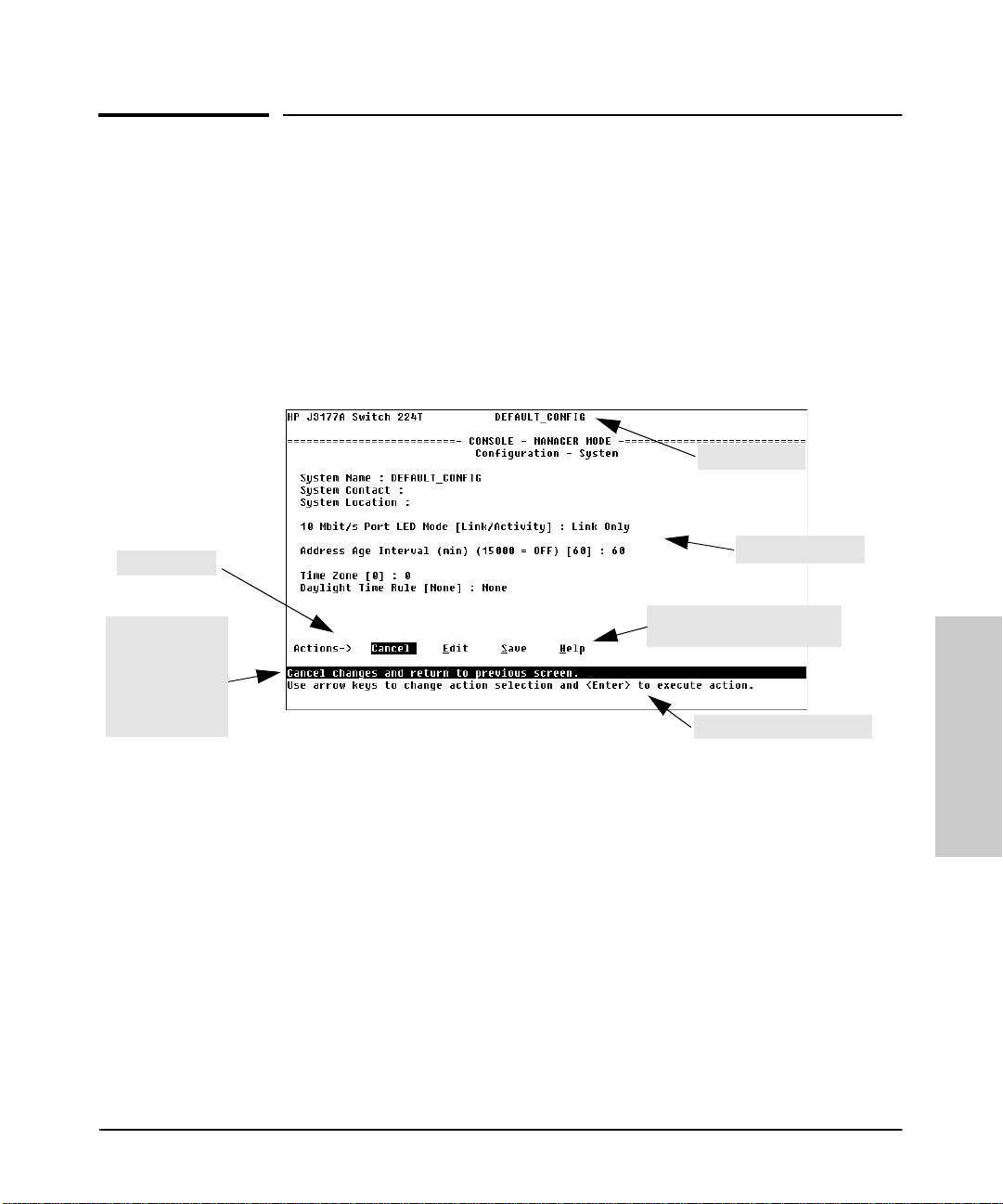
For example, in the System configur ation screen:
system name
actions line
Help line
describing the
selected action
or selected
parameter field
(in thi s case, t he
Cancel option)
param eter fields
Help descri bing each of the
items in the paramet er m enu
The Switch Console
navigat ion instructions
Figure 3-4. Elements of Screen Structure
“Form s ” Design. The configuration screens, in particular, operate similarly
to a number of PC applications that use forms for data entry. When you first
enter these screens, you see the curren t co n f igu r ation for the item you have
selected. To change the configu ration, the basic operation is to:
1. press [E] to select the Edit action
2. navigate through the screen making ALL the necessary configuration
changes, then
3. press [Enter] to return to the action line. F r om there you can select to save
the configuratio n changes or to cancel the changes. Cancel returns the
configuration to the val ue s you saw when you first entered the screen.
See the next page for specific instructions on using the console screens.
3-9
Page 28

The Switch Console
Screen St ructure and Navigation
Table 3-1. How To Navigate in the Console
Task: Actions:
Execute an acti on fr om an
“Actions-[>] list:
Use either of the followi ng methods:
■ Use the arrow keys ( [<] ,or [>] ) to highl ight the actio n you
want to execute, then press [Enter].
■ Press the key correspondi ng to the capital letter in the
action name . For example, in a configu ration menu, press
[E] to select Edit and begin editi ng paramet er values.
Reconfigure (edit) a
parameter setting or a
field:
1. Select a confi guration i tem, such as System. (See figur e 3-
4.)
2. Press [E] (for E
dit on the Actions line).
3. Use [Tab] or the arrow keys to highlight the item or field.
4. Do one of the following:
• If the par amet er has pr eco nfigu red va lues, us e the Spac e
bar to select a new option (the help line instructs you to
“Sel ect” a val u e)
• If there are no preconfigured values, type in a value (the
help line instructs you to “Enter” a value)
5. If y ou want to ch ange an other pa ramete r val ue, ret urn t o ste p
3.
6. If you are finished editing parameters in the displayed screen,
press [Enter] and do one of the following:
• To save any configuration changes you have made (or if
you have made no changes), press [S] (for the Save action).
• To exit from the screen without saving any changes that
you ha v e m ade, pr e ss [C] (for Cancel).
Note:
Some parame ter changes are activat ed w hen you
execute Sav e, and i t is t her efor e not necessa ry to r eboot t he
switch after making the se changes. But if an asteri sk appears
next to any menu item you reconfigure, it is necess ary to
The Switch Console
reboot th e switch to implement the change. In this case,
rebooting should be done after you have made all desi red
changes and t hen returned to the Main Menu.
7. When y ou are fi nished editing paramet ers, re turn t o the Mai n
Menu.
8. If nece ssary, reb oot the switch by hi ghlightin g Reboot Switch
and pressing [Enter]. (Refer to t he
Note
, above.)
3-10
Page 29

The Switch Console
Using Password Security
Using Password Security
There are two levels of console access: Man ager and Operator. For security,
you can set a password on each of these leve ls.
Level Actio n s P er m it ted
Manager: Access to all console interface areas.
This is the defaul t level .
to starting the current console session, then anyone using the console can
access any ar ea of the console interf ace.
Operator: Access to the Status and Counters, Event Log, and minimal Configuration.
Use of the LOGOUT command.
On the Operator level, the Advanced Commands, Set Passwords, Download
OS, and Reboot options are no t available in the Main Menu.
That is, if a Manager password h as
not
been set prior
To use password security:
1. Set a Manager password (and an Operator password, if applicable for your
situation).
2. Activate the passwor d(s ) by exiting from the current console session.
If you do steps 1 and 2, above, then the next time a console session is started,
the console interface will prompt you for a password. Assuming that both a
Manager password and an Operator password hav e been set, the level of
access to the console interface will be determined by which password is
entered in response to the prompt.
If you set a Manager password, you may also want to configure the
Connection Inactivity Time parameter in the Serial Link configuration
screen (page 4-15 ). This caus es the consol e session to end after the speci fied
period of inactivity, thus giving you added security against unauthorized
console access. (Once a Manager password is set and the console ses sion is
ended, access to the full cons o le in ter f ace for any subsequent sessio n s
requires the Manager password t o be entered .)
The Switch Console
3-11
Page 30
The Switch Console
Using Pas sw ord Security
Note If there is only a Manager password set (with no Operator password), and the
Manager password is not entered co rrectly when the co nsole sess ion begin s,
the switch console operates on the Operator level.
If there is both a Manager password and an Operator password, but neither is
entered correctly, access to the console will be denied.
If a Manager password is not set, anyone having access to the console
interface can operate the console with full manager privileges, regardless of
whether an Operator password is set. It is recommended that if you want
to restrict access to the console, you should always set at least a Manager
password. Then, if you also want to restrict access to the minimal Operator
capabilities, also set an Operator password.
Passwords are case-sensitive.
The rest of this section covers how to:
■ Set a Password
■ Delete a Password
■ Recover from a Lost Password
To set Manager and Operator pass w ords:.
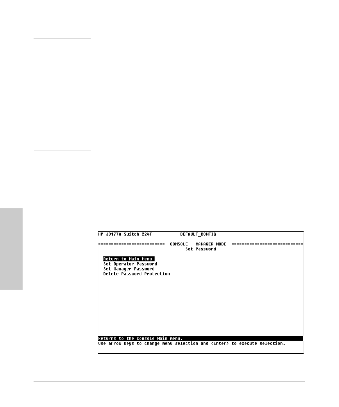
1. From the Main Menu select Set Passwords. This screen appears:
The Switch Console
Figure 3-5. The Set Password Screen
3-12
Page 31

The Switch Console
Using Password Security
2. To set a new password:
a. Select Set Manager Password or Set Operator Password.
You will then be prompted with Enter new password.
b. T yp e a password of up to 16 characters and press [Enter]. (Remember
that passwords are case-sensitive.)
c. When prompted with Enter new password again, retype the
new password and press [Enter].
d. To set another password, return to step 2a. Otherwise, go to step 3.
3. Select Return to Main Menu to exit from the Set Password screen.
After a password is set, if y ou use LOGOUT or reboot or reset the switch, you
will be prompted to enter the password to start a new console session.
To Delete Password Protection:
This procedure deletes both passwords (Manager and Operator).
1. Enter the console at the Manager level.
2. From the Main Menu select Set Passwords. You will then see the screen
shown in figure 3-5.
3. Select Delete Password Protection. You will then see the following
prompt:
Continue Deletion of password protection? No
4. Press the Space bar or press [Y] to select Yes, the n p re ss [Enter].
5. Press [Enter] to clear the Password protection messag e.
6. Select Return to Main Menu to exit from the Set Password screen.
To Recover from a Lost Manager Pass word:
If you cannot start a console ses sion at the manager level because of a lost
Manager password, you can clear t he password by getting physical acces s to
the switch and pressing and holding the Clear button on the Management
Module for at least one second.
The Switch Console
3-13
Page 32

The Switch Console
Using Pas sw ord Security
To Recover from a Lost Operator Password:
To recover from a los t Oper ator pa ssword, del ete al l passw ords as des cribed
above, then re -enter new passwords. If you have phys ical access to the switch,
press the Clear button on the Management Module to clear all password
protection, then ente r new passwords as described earlier in this chapter. If
you do not have physical access to the switch, you will need the Manager
password:
1. Begin a console session at the Manager level (by entering the Manager
password when the password prompt appears).
2. Select Set Passwords from the Main Menu.
3. Select Delete Password Protection.
4. When you see the prompt to continue delet ion, use the Space bar to select
Yes, then press [Enter]. You will then see the following message:
Password protection removed.
This means that both the Manager and Operator password s have been
removed and the switch no longer has password protection.
5. Press [Enter].
6. Set new passwo r ds as described on page 3-12.
The Switch Console
3-14
Page 33

The Switch Console
Rebooting the Switch
Rebooting the Switch
Rebooting the switch terminates the current console session and performs a
reset of the operating system. Some of the reasons for performing a reboot
include:
■ Activating certain configuration changes that require a reboot
■ Resetting statistical counters to zero
■ Clearing the switch address table
To Reboot the switch, use the Reboot Switch option in the Main Menu. (If
a Manager password has been previously set, Reboot Switch appears only
if this password is entered at the beginning of the console session.)
the Reb oo t Sw itch opt i on
Figure 3-6. The Reboot Switch Option in the Main Menu
The Switch Console
3-15
Page 34

The Switch Console
Rebooti ng the Switch
Rebooting To Activa te Configur a tion Changes . Configuration changes
for some parameters become effective as soon as you save them. However,
you must reboot the switch in order to implement any changes to any
parameters in the following areas:
■ IPX Service
■ Internet (IP) Service
■ Serial Link
If configuration changes requiring a reboot have been made, the switch
console displays an asterisk next to the configuration menu item in which the
change has been made. For exampl e, if you change and save paramet er values
for the swi tch ’s IP configuration, the need for rebooting the sw itch would be
indicated by an asterisk appearing in the following screen:
asterisk indicates a
configuration change
that requires a reboot
in order to take effect
The Switch Console
reminder to reboot the sw itch to
activate configuration changes.
Figure 3-7. Example of a Confi guration Change Requiring a Reboot
3-16
Page 35

The Switch Console
Advanced Commands
Advanced Comm a nds
Selecting Advan ced Commands fr o m the Main Menu pres ents a command
prompt from which you can enter the fol lowing system management commands:
Listing of Commands Available under Advanced Commands
! Get (TFTP) Ping Time
ClearLED Help Print Version
Config History Put (TFTP) W alkMIB
Date IPXPing Redo Zget
Delete LinkTest Repeat Zput
Exit Log SetMIB
GetMIB Page Telnet
To get a definition of these commands and their syntax, enter Help at the
command prompt. When you see — MORE — at the bottom of the screen:
■ To advance the display one line at a time, use [Enter].
■ To advance the display one screen at a time, use the Space bar.
The Switch Console
If you want to stop the help listing, press [Q].
How To Use the A dvanced Comm ands:
1. To access the command prompt, use the arrow keys to highlight
Advanced Commands in the Main Menu and press [Enter].
2. The command prompt ap pears near the b ottom of the scre en. The te xt in
the prompt matches the System Name parameter. For example, in the
factory default configuration (no system name configured), the command
prompt is DEFAULT_CONFIG:
3. Type in the command you want to execute and pre ss [Enter]. For example,
to set the time to 9:55 a.m. you would execute the following co mman d:
DEFAULT_CONFIG: time 9:55 [Enter]
How To Exit from the command prompt:
Type exit and press [Enter] to return to the Main Menu.
3-17
Page 36

Page 37

4
Configuring the Switch From the Console
Overview
This chapter provides an overview of the Switch 208/ 224 Management Module
configuration features.
Default Configuration. In its factory default configuration, the Switch
208T and 224T with a Switch Management Module installed automatically
operates as a multiport learning bridge. All ports are enabled, Spanning Tree
Protocol support is disabled, and SNMP network management is enabled over
IPX and IP (by way of Bootp).If you wish to “fine-tune” your switch for the
specific performance, security, and diagnostic needs in your network, you
may choose to reconfigure cer tain switch parameters.
Note In the factory default configuration, the Spanning Tree Protocol (STP) is off.
However, if the topology of your network includes any redundant data paths
between switches or bridges, you should enable support for STP. See “Spanning Tree Configuration” (page 4-17).
Configuration Features. The Switch Management Module enables you to
configure the following switch features. For information on individual configuration parameters, use the online Help provided with each configuration
screen in the console user interface.
■ System (page 4-4)
■ Ports (page 4-5)
■ IPX Service (page 4-6)
■ Internet (IP) Service (page 4-8)
■ SNMP Communities (page 4-12)
■ Trap Receivers (page 4-14)
■ Serial Link (page 4- 15)
■ Console (page 4-16)
■ Spanning Tree (page 4-17)
■ Network Monitoring Port (page 4-19)
4-1
Configuring the S witch From
the Console
Page 38

Configuring the Switch From the Console
Overview
To get Help on indi vidu al parameter descripti ons. In all screens except
the Advanced Commands screen there is a Help option in the Actions
menu. Whenever the Actions menu is acti ve, you ca n display Help for that
screen’s parameters by pressing [H]. (The Actions menu is active whenever
any of the choices in the Actions menu is highlighted.) For example:
highlight on any
item in the
Actions menu
indicates t h at th e
Actions menu i s
help line
default values are
shown in brackets [ ]
pressing [H] or highlighting
elp and pressing [Enter]
H
displays He lp f or th e
parameters listed in the
upper par t of the screen
Configuring the Swi tch From
Figure 4-1. Example Showing How To Di splay Help
To get Help on the actions or data fields in each screen: Use the arrow
keys ( [<], [>], [^], or [v]) to select an action or data field. The help line under
the Actions menu describes the currently selected action or data field. (For
guidance in how to navigate in a configuration screen, see the in structions
provided at the bottom of the screen, or refer to “Scre en Structu re and
Navigation” on page 3-9.)
the Console
4-2
Page 39

Configu ring the Switch From the Console
Configurable Features
Configurable Fea ture s
How To Access the Switch Configuration:
1. Begin at the Main Menu and select Configuration and the Confi guration menu appears as shown in figure 4-2.
Figure 4-2. The Configurat ion Menu
2. Use the arrow keys ( [<], [>], [^], and [v] ) to highlight the configuration
topic you want, then press [Enter].
3. Refer to the appropriate sections in the remainder of this chapter for
information on config uring specific features.
Configuring the S witch From
the Console
4-3
Page 40

Configuring the Switch From the Console
Configurable Featur es
System Configuration
This screen configures basic switch management information, including system identification information, address aging, the port LED behavior, and time
zone parameters :
system name
Configuring the Swi tch From
Figure 4-3. The System Configuration Screen (Default Values)
Note To help simplify administration, it is recommended that you configure
System Name to a character string that is meaningful with in yo u r system.
To set the time and date, set the Time Protocol parameters for your time server
(page 4-8) or use the time and date commands available under Advanced
Commands.
10 Mbit/s Port LED Mode. Using this parameter , the LEDs associated with
the 10 Mbit/s network ports on the switch can be configured to operate in one
of two ways:
■ Link/Activity - In this mode, each LED indicate s the connection statu s of
the port for 3 seconds after the networ k cable is first installed and every
time the switch is powered on. After 3 secon ds, the LED is used to
indicated network acti vity on that port--it flashe s briefly with each packet
the Console
4-4
that is either recei ved or tran smi tted on the port.
■ Link Only - In this mode, the LED continues to indicate the connection
status and does not convert to an activity indicator.
Page 41

Configu ring the Switch From the Console
Configurable Features
Port Configuration
This screen configu res the operating state (e nabled or disabled) and mode for
each port. The availabl e modes for each p o rt type are listed and des cribed in
the online help for the screen. To view this information, select the Help action .
The read-only fields in this screen display the port numbers and port types.
read-only fields
Figure 4-4. Example of the Port Configuration Scree n
The screen image in figur e 4-4 sho ws the default Mode value for each of the
port types availabl e on the Switch 208/224. Select the Help actio n to see the
other modes available for each p o rt type.
4-5
Configuring the S witch From
the Console
Page 42

Configuring the Switch From the Console
Configurable Featur es
IPX Service
The Switch Management Module, by default, has IPX communication enabled.
This allows the switch to be managed from an SNMP network management
station in an IPX network. The Switch Management Module automatically
configures the IPX network address using its MAC address as the node address
(displayed i n th e Node Address field in t he I PX Ser vice configurat ion screen
as shown in figure 4-5), and it learns the IPX network number by listening on
the network.
In the IPX Service confi gura tion scree n, you can disabl e IPX manageme nt by
changing the IPX Enabled va lue to No . You can al so configur e an IPX ga teway
frame encapsulation type so that the switch can be managed from a remote
IPX network as described in the next section.
read-only fi eld
Configuring the Swi tch From
default setting for
“IPX Enabled”
Figure 4-5. The IPX Service Configuration Screen (Default Values )
the Console
4-6
Page 43

Configu ring the Switch From the Console
Configurable Features
(Optional) How To Configure IPX for Management from a Remote IPX
Network. To enable management from a remote IPX network, you must
configure the gateway encapsulation type.
1. From the Configuration screen, select IPX Service to display the above
screen.
2. Press [E] (for E
dit).
3. If the IPX Enabled parameter is not already set to “Yes” (the factory
default), then select this parame ter and p ress the Spa ce bar to sel ect Yes .
4. Select the Gateway Encap field and use the Space bar to select the appropriate gateway encapsulation for the gateway device.
5. Press [Enter], then [S] (for S
ave).
6. Return to the Main Menu and reboot the switch.
4-7
Configuring the S witch From
the Console
Page 44

Configuring the Switch From the Console
Configurable Featur es
Interne t (IP) Service
For managing the Switch 208/224 from an SNMP network management station
over an IP network, or for using the switch console through a Telnet session,
use the IP Service screen to configur e:
■ IP address, subnet mask, and (optionally) the gateway address for the
switch so that it can be managed in an IP network
■ The time server information (used if yo u want the switch t o get it s tim e
information from another device operating as a Timep server)
You can manually configure an IP address, subnet mask, and a Gateway IP
address by setting the IP Config parameter to Manual. Or, you can use
Bootp to configure IP for the switch from a Bootp server. In this case you must
also configu re your Bootp server accordingly. If you plan to use Bootp, refer
to “Bootp Operation” in chapter 6, “Using SNMP to Monitor and Manage the
Switch”. Otherwise, set the IP Config parameter to Manual and then
manually enter the IP address an d subnet mask yo u want for the Switch 208/
224.
Configuring the Swi tch From
The default setting f or Tim e
Protoco l Enabled is No.
Setting it to Yes as shown
here, then pr essing [v] or [Tab]
causes the Timep Server
Address an d Timep Poll
Interval parameters to
appear. For descript ions of
these parameters, select the
Help action for this screen.
Figure 4-6. Example of the IP Serv ice Configuration Screen (Default Values)
the Console
4-8
Page 45

Configu ring the Switch From the Console
To manually configure the switch for IP:
1. From the Configuratio n screen, select Internet (IP) Service to
display the above screen.
Configurable Features
2. Press [E] (for E
3. Select the IP Config field and use the Space bar to select Manual.
4. Select the IP Address field and enter th e IP address you want to assign
to the switch.
5. Select the Subnet Mask field and enter the subnet mask for the IP
address.
6. If you want to reach off-subnet destinations, select the Gateway field
and enter the IP address of the gateway router.
7. Press [Enter], the n [S] (for S
8. Return to the Main Menu and reboot the switch.
dit).
ave).
Using Bootp
In its default configuration, the switch is configured to enable Bootp operation. However, if an IP address has previously been configured or if the IP
Config parameter has been set to Disabled, then you will need to use thi s
procedure to reconfigure the parameter to enable Bootp operation.
This procedure assum es that a Bo otp database record has already bee n
entered into an appropriate Bootp server, and that the necessary network
connections are in pla ce. For samples of Bootp server table entr ies, see “Bootp
Database Entries” later in this chapter.
To configure the switch for Bootp:
1. In the Main Menu, select Configuration .
2. In the Configuration screen select Internet (IP) Service.
3. Press [E] (for Edit mode), then use [v] to move the cursor to the
IP Config parameter field.
4. Use the Space bar to select the Use Bootp option for the IP Config
parameter. (This disables access to the IP Address, Subnet Mask, and
Gateway parame te rs .)
5. Press [Enter] to exit from edit mode, then press [S] to save the configura tion
change.
4-9
Configuring the S witch From
the Console
Page 46

Configuring the Switch From the Console
Configurable Featur es
When you reboot the switch with Bootp enabled, it will do one of the foll owing:
■ Receive a minimal configuration (IP address and subnet mask).
■ If the reply provides information for downloading a configuration file, the
switch then uses TFTP to d ownload th e file from the designated so u rc e,
then reboots itself . (This assu mes that the switch has co nnectivi ty to the
TFTP file server specified in the Bootp database configuration record and
that the Bootp database reco rd is correctly config ured.)
Bootp Operation
Bootp is used to download configuration data to the switch from the Bootp
server that is configured on the switch. Either a minimal IP configuration or
a full configuration can be retrieved from the Bootp server.
Note The switch supports only the DHCP (Dynamic Host Configuration Protocol)
implementations that are backwards compatible with Bootp.
The Bootp Process
Whenever the switch reboots with the IP Config parameter set to Use Bootp
(the default), Bootp requests are broadcast on all local networks. When the
Bootp server receives the request it searches its Boot p d atabase for a reco rd
entry that matches the Switch Management Module MAC address, which is in
the Bootp request. If a match is found, the configuration data in the associated
database record is returned to the switch. For most Unix systems, the Bootp
database is contained in the /etc/bootptab file.
Configuring the Swi tch From
Bootp Database Record Entries
An entry in the Bootp table file /etc/bootptab to update an IP address
and subnet mask to the switch configured in the switch would be similar to
this entry:
switch208224:\
ht=ether:\
ha=080009123456:\
sm=255.255.248.0:\
lg=11.22.33.44:\
hn:\
ip=55.66.77.88:\
vm=rfc1048:
the Console
4-10
Page 47

Configuring the Switch From the Console
Configurable Features
An entry in the Bootp table file /etc/bootptab to tell the switch where to
obtain a configuration file download would be similar to this entry:
switch208224:\
ht=ether:\
ha=080009123456:\
sm=255.255.248.0:\
lg=11.22.33.44:\
hn:\
ip=55.66.77.88:\
T144="switch.cfg":\
vm=rfc1048:
where:
switch208224 is a user-defined symbolic name to help you find the correct section
of the bootptab file. If you have multiple switches that will be using
Bootp to get their IP configuration, you should use a unique
symbolic name for each switch.
ht is the “hardware type”. For the HP AdvanceStack switch, set this
to ether (for Ethernet). This tag must precede the ha tag.
ha is the “hardware address”. Use the Switch Management Module's
12-digit MAC address. Make sure you use the address displayed
on the front of your Switch Management Module.
sm is the subnet mask of the subnet in which the switch is installed.
lg TFTP server address (source of final configuration file).
hn send nodename (boolean flag, no “=value” needed).
ip is the IP address to be assigned to the switch.
T144 is the vendor-specific “tag” assigned to HP; the name of the
configuration file to download is in quotes.
vm is a required entry that specifies the Bootp report format. For the
HP AdvanceStack switch, set this parameter to rfc1048.
Notes for the bootptab file:
■ Blank lines and lines beginning with the pound sign (#) are ignored.
■ Make sure you include a colon (:) and a back slash (\) as a continuation
indication at the end of each line except the last one. The last line should
end with just a colon (:)
■ Spaces are not allowed between the characters on a line.
■ Names, such as switch208224 must begin with a letter and can only
contain letters, numbers, periods, or hyphens.
Configuring the Switch From
the Console
4-11
Page 48

Configuring the Switch From the Console
Configurable Featur es
SNMP Communities
This screen enables you to add, edit, or delete SNMP communities. Use this
feature if you expect to manage the Switch 208/224 from an SNMP management station. You can configure up to five SNMP communities, each with
either an operator-level or a manager-level view, and either restricted or
unrestricted write access. (For more on this topic, refer to chapter 6, “Using
SNMP To Monitor and Manage the Switch”, and to the online Help.)
This screen gives an overview of the SNMP communities that are
current ly configu red. All fie lds in this scr een are read-only.
Add and Ed it o ptions are used to mo dify
the SNMP options. See figure 4-8.
Configuring the Swi tch From
Figure 4-7. The SNMP Communities Screen (Default Values)
Caution Deleting the community named “public” disables many network management
functions (such as auto-discovery, traffic monitoring, and threshold setting).
If security for network management is a concern, it is recommended that you
change the write access for the “publ ic” community to “Restricted”.
How To Conf igure the Switch for SNMP Communities.
Ensure that the switch has been configured for IP and/or IPX service.
the Console
4-12
1. From the Configuration screen, select SNMP Communities to display a
screen similar to figure 4-7.
2. Press [A] (for A
dd) to display the following screen:
Page 49

Configu ring the Switch From the Console
Configurable Features
If you ar e ad ding a
community, the fields in
this screen are blank.
If you are editing an
existing com m unity, th e
values for the selected
community appear in the
fields.
type the value for
this field
use the Space bar
to select val ues fo r
other fields
Figure 4-8. The SNMP Communities Add or Edit Screen
Note If you choose to not restrict the use of a community to specific network
management stations, you do not need to list the manager addresses on this
screen. You can use this screen to just configure community names and to set
the MIB View and Write Access for each community.
All community nam es tha t you create u sin g this s creen can be use d to acces s
the switch into which the Switch Management Module is installed. Any
management sta tion using the correc t community name may access the switch
with the correspondi n g MIB Vi ew and Wri t e Access levels.
If you want to restrict access to one or more specific management st ations for
a given SNMP community, lis ting the addresses of those stati ons on this screen
creates that limitatio n . For each SNMP Community, you can authorize up to
ten management stations by entering their IP and/or IPX addresses into the
Manager Address field.
3. Enter the appropriate value in each of the above fields (u se the [Tab] key
or arrow keys to move from one field to the next).
4. Press [Enter], then [S] (for S
ave), and the new SNMP Community configu-
ration is automatically activated.
5. Return to the Main Menu to access other functions.
4-13
Configuring the S witch From
the Console
Page 50

Configuring the Switch From the Console
Configurable Featur es
Trap Receivers
This screen enables you to configure up to ten IP and/or IPX management
stations (trap receivers) to receive SNMP trap packets sent from the switch.
Trap packets describe speci fic event types. (These events are the same as the
log messages dis p layed in the event log.) The protocol, addr ess , and community define which ma nagement stations r eceive the traps . Check the event log
to help determine why the authentication trap was sent. (Refer to chapter 3
for information on the event log.)
Configuring the Swi tch From
Figure 4-9. The Trap Receivers Configuration Screen (Default Values)
the Console
4-14
Page 51

Configu ring the Switch From the Console
Configurable Features
Serial Link Configuration
Use the serial link configuratio n screen to adjust the console RS-232 configuration to customize the connection with the PC, terminal, or modem you are
using for console access. Refer to appendix B, “Modem Configuration” for
information on modem settings. Refer also to “Console Configuration” on the
next page.
Figure 4-10. The Serial Link Configuration Screen (Defau lt Values)
Configuring the S witch From
the Console
4-15
Page 52

Configuring the Switch From the Console
Configurable Featur es
Console Conf igu rat ion
This screen lets you enable or disable inbound Telnet access and control the
types of events displayed in the event l og. Also specifies the terminal t ype and
the console screen refresh interval used by the st atistics screens (that is, the
frequency with which statistics are updated on the statistics screens).
Note “Inbound” Telnet is Telnet access to the switch console from another device.
“Outbound” Telnet, which is using Telnet through the switch console to access
another device, is always enabled as long as the Switch Management Module
has been configured with a valid IP address. (To configure an IP address for
the switch, refer to “Intern et ( I P) Serv ice Features” on page 4-8.)
The Switch Management Module supports one inbound and one outbound
Telnet sessions simultaneously.
default i nbound
Telnet setting
Configuring the Swi tch From
Figure 4-11. The Console Configuration Screen (Default Values)
the Console
4-16
Page 53

Configu ring the Switch From the Console
Configurable Features
Spanning Tree Configuration
Use this screen t o activa te the IEEE 802. 1d Span ning Tree Protocol (S TP) on
the switch and to a djust spanning tr ee parameters , if necessary . In the factory
default, STP is off. If there are any redundant paths (loops) between nodes in
your network, you should set the Spanning Tree Enabled parameter to Yes.
This ensures that all redundant ports (those providing backup parallel connections) are in a blocking state and not used to forward data.
The switch automatical ly senses port identity and type, and automatic ally
defines port cost and prio rity for each type. The inte rface allo ws you to adju st
the Cost and Priority for each port, as well as the global STP parameter values
for the switch.
To configure the STP parameters: In most cases, the default STP parameter settings are adequ ate. In cases where it is n ot, use this proced ure to make configuration ch anges.
Caution If you en able STP (s tep 4), it is recommen ded that you leave the remainder of
the STP parameter settings at their default values until you have had an
opportunity to evaluate STP performance in your network. Becaus e incorrect
STP settings can adversely affect network performance, you should avoid
making changes without having a strong understanding of how STP operates.
To learn the details of STP operation, refer to appendix D, “Spanning Tree
Operation”, and examine the IEEE 802.1d standard.
1. From the Main Menu, select Configuration.
2. In the Configuration sc re en , sel ect Spanning Tree .
3. Select Edit to highlight the Spanning Tree Enabled parameter.
4. Press the Space bar to select Yes . (This enables STP.)
Configuring the S witch From
the Console
4-17
Page 54

Configuring the Switch From the Console
Configurable Featur es
Figure 4-12. Example of the STP Configuration Screen
5. If the remaining STP parameter setti n gs ar e ad equ ate fo r your ne twork ,
go to step 8.
Configuring the Swi tch From
the Console
6. Use [Tab] or the arrow keys to select the next parameter you want to
change, then type in the new value. (If you need information on STP
parameters, press [Enter] to select the Actions line, then press H
to get
help.)
7. Repeat step 6 for each additiona l para meter yo u want to change.
8. When you are finished editing parameters, press [Enter] to return to the
Actions line.
9. Press [S] to save the currently displayed STP parameter settin gs and return
to the Configuration menu. The Spanning Tree configuration is automatically activated when it is saved.
10. Return to the Main Menu to access other functions.
4-18
Page 55

Configu ring the Switch From the Console
Configurable Features
Network Monitoring Port
You can designate a port for monitoring traffic on any one of the other ports
on the switch. This is accomplished by copying all traffic from the specified
port to the designated monitoring po rt. The feature is also referred to as
“mirroring”.
How To Conf igure the Switch for Monitoring: This procedure describes configuring the switch for monitoring when monitoring is disabled. (If monitoring has already been enabled, the screens will appear differently than shown in this procedure.)
1. Select Network Monitoring Port from the Configuration screen.
2. In the Actions menu, press [E] (for Edit).
3. If monitoring is currently disabled (the default) then enable it by pressing
the Space bar (or [Y] ) to select Yes.
enable monitoring by
setting this parameter
to “Yes”
Figure 4-13. The Default Network Monitoring Configuration Screen
4. Press [v] to display a screen si milar to the fol lowing an d move the cursor
to the Monitoring Port parameter.
4-19
Configuring the S witch From
the Console
Page 56

Configuring the Switch From the Console
Configurable Features
Figure 4-14. Example of Selecting a Monitoring Port
5. Press the Space bar or type the port number to select which port to use
for the monitoring port
Configuring the Swi tch From
6. Press [v] to move to the Monitored Port field and press the Space
bar or type the port number to select the port you want to monitor.
7. Return to the Main Menu to select other functions. You don’t need to
reboot the switch; the Network Monitoring Port configuration is dynamically activated .
Note The port you select as the Monitoring Port is identified on the port status and
counter screens and the port configuration screens with -MP after the port
number
The port you select as the Monitoring Port cannot participate in Spanning Tree
protocol, so it will not be displayed on the Spanning Tree configuration or
status screens.
the Console
4-20
Page 57

Configu ring the Switch From the Console
Saving Configurations
Saving Configurations
Once you have completed all your switch configuration changes , it is a good
idea to save the configuration in a secure location. The co n f igu ration is
contained in a file that can be transferred to a PC or server. See “Transferring
Switch Configurations” in appendix C, “File Transfers” for the procedures to
save your switch configuration.
4-21
Configuring the S witch From
the Console
Page 58

Page 59

5
Operation From the Console
Monitoring Switch Operation From the
Console
Overview
The Main Menu in t he switch’s console interface gives you access to the
following sources of read -o n ly d ata fo r hel pin g yo u to monitor, analyze, and
troubleshoot switch operation:
Table 5-1. Read-Only Monitoring and Analyzing Features
Main Menu
Item
Status and
Counters
Menus
Data Type Purpose
Switch Information Lists switch-level operating information.
Port Status Displays the operational status of each port.
Port Counters Summarizes port activity.
Monitoring Switch
Address (forward ing) Table Lists t he MAC addre sses of nodes th e switch has
detected on the network, along with the
corresponding switch port.
Port Address Table Lists the MAC addresses that the switch has
learned from the selected port.
Spanning Tree Information Lists Spanning Tree data for the switch and for
individual ports.
Event Log Lists event messages generated by the switch.
5-1
Page 60

Monitoring Switch
Monitor ing Switch Operation From the Console
Status and Counters Menu
Status and Co unters Menu
Select Status and Counters from the Main Menu to display the Status and
Counters menu:
Operation From the Console
5-2
Figure 5-1. The Status and Counters Menu
Each of the above menu items accesses the read-only screens described on
the following pages. Refer to the online help for a description of the entries
displayed in these screens.
Page 61

Monitoring Switch Operation From t he Console
Status and Co unters Menu
Switch Information
Figure 5-2. Example of Switch Information
This screen tells you the foll o wi ng inf orm atio n ab out the switch and the
Switch Management Module:
■ the version of the OS (operating system) code
■ the version of the ROM (read-only memory) code
■ the MAC address of the Switch Management Module
■ the identity of the expansion module, if one is installed in the Expansion
Slot in the back of the switch:
• None indicates that no module is installed
• Router/Rem Access indicates that a r outer m odule ( for ex ample,
the HP J3138A Internet Router Module), or a remote access module
(for example, th e HP J3230A LanRover/10A by Shiva) is in stalled.
■ a dynamic indication of how individual switch resources are being used
Operation From the Console
Monitoring Switch
5-3
Page 62

Monitoring Switch
Monitor ing Switch Operation From the Console
Status and Counters Menu
Port Status
Operation From the Console
Figure 5-3. Example of Port Status
For each port, this screen provi d es you the foll o wi n g info rmatio n :
■ Port -- the port number (note that even if a transceiver module is not
install ed in the tr a nsceive r slot in the fr ont of the switch-- p o rt B , a
port B entry is displayed in the list)
■ ID -- the port ID number to use for SNMP MIB access
■ Type -- the network technology type of the port
■ Media -- the type of network media connected to the port
■ Enabled -- whether the port is enabled (Yes or No)
■ Status -- the operational status of the port (Up -- operating correctly, or
Down -- not operating correctly)
■ Mode -- the port’s operating mode
Use the Help action item on this screen to see a list of possible values for
each of these items, and definitions of those values.
5-4
Page 63

Monitoring Switch Operation From t he Console
Status and Co unters Menu
Port Counters
Figure 5-4. Example of Port Counters
This screen en ables you to determine the traffic patterns for each port. Port
Counter features include:
■ Dynamic display of counters summarizing the traffic on each port since
the last reboot or reset
■ Option to reset the counters to zero (for the current console session). This
is useful for troubleshooting. Refer to the Note, below.
■ An option to display the link status, and further port activity details for a
specific port ( Show details ). When you se lect the Show details
action, you are prompted to select the switch port. A sample detailed port
counters screen is shown in figure 5-5.
Operation From the Console
Monitoring Switch
Note The Reset action on this screen and the Show Details screen resets the
counter display to zero for the current session, but does not affect the
cumulative values in the actual hardware counters. ( I n comp liance with the
SNMP standard, the values in the hardware counters are not reset to zero
unless you reboot or reset the switch.) Thus, using the Reset action resets
the displayed counters to zero for the current session only. Exiting from the
console session and starting a new session restores the counter displays to
the accumulated values in the hardw ar e counter s.
5-5
Page 64

Monitoring Switch
Monitor ing Switch Operation From the Console
Status and Counters Menu
Port Counters - Show Details
Operation From the Console
Figure 5-5. Example of Port Counters - Show Details
5-6
This screen shows you additional counters for the selected port. For definitions of these counters, use the Help action.
In addition to the counters, this screen displays the status of the network
connection to this port ( Link Status ), and the MAC address of the Switch
Management Module. This MAC address can be used to perform level-2
network connectivity tests (link tests) through this port. See chapter 7,
“Troubleshooting” for more information about link tests.
Page 65

Monitoring Switch Operation From t he Console
Status and Co unters Menu
Address Tab le
Figure 5-6. Example of the Addres s Table
This screen lets yo u easily determine which switch port is being u sed to access
a specific device on the network. The listing includes:
■ The MAC addresses that the switch has learne d from network devices
attached to the switch
■ The port on which each MAC address was learned
Operation From the Console
Monitoring Switch
You can use the S
earch action at th e bottom of the sc reen to locate a spec ific
device (MAC address).
5-7
Page 66

Monitor ing Switch Operation From the Console
Status and Counters Menu
Port Address Table
This screen lets you easily determine which devices are attached to the
selected swi tch port by li stin g all o f the M AC addres ses d etected on that p ort.
Monitoring Switch
Operation From the Console
You can use the S
earch action at the bottom of the screen to determine
whether a specific device (MAC address) is connected to th e selected port.
To use the por t address table:
1. Select Port Address Table from the Status and Counters menu.
Use the Space bar to select the port for
which you want to display the add ress table.
5-8
Figure 5-7. Example of How To Access the P ort Address Table
2. When the Select Port prompt appears, press the Space bar to display
the number of the port you want to examine, then press [Enter]. (See figure
5-7, above.)
Each port is identified by its port number.
Page 67

Monitoring Switch Operation From t he Console
Status and Co unters Menu
In this exa mple, several MAC addresse s
accessed through port 16 appear in the
initial listing. To view any additional
addresses th at may be in t he li st ing, use
the N
ext page action.
Operation From the Console
Monitoring Switch
Figure 5-8. Example of a Port Address Table for a Specific Port
5-9
Page 68

Monitoring Switch
Monitor ing Switch Operation From the Console
Status and Counters Menu
Spanning Tree (STP) Information
Use this screen to dete rmine current switc h-level ST P parameter settings a nd
statistics.
Operation From the Console
5-10
Figure 5-9. Example of Spanni ng Tree Information
Page 69

Monitoring Switch Operation From t he Console
Status and Co unters Menu
You can use the Show ports action at the bottom of the screen to display
port-level information and parameter settings for each port in the switch
(including port type, source MAC address, cost, priority, operating state, and
designated bridge).
Operation From the Console
Monitoring Switch
Figure 5-10. Example of STP Port Information
Caution Because incorrect STP settings can adversely affect network performance,
you should avoid making changes without having a strong understanding of
how STP operates. For more on STP, refer to appendix D, “Spanning Tree
Operation” an d read the IEEE 802.1d standards document.
5-11
Page 70

Monitor ing Switch Operation From the Console
Event Log
Event Log
The Event Log records operating events as single-line entries listed in chronological order. Each entry is composed of five field s:
Monitoring Switch
Operation From the Console
Severity Date Time System Module Event Message
I 08/05/96 10:52:32 ports: port 1 enabled
Severity
Date
Time
System Module
generated the log entry.
Event Message
is one of the following codes:
I (information) indicates routine events.
W (warning) indicates that a service has behaved unexpectedly.
C (critical) indicates that a severe switch error has occurred.
D ( d eb u g) reserved for HP internal diagnostic information.
is the d a te in mm/dd/yy format that the entry was placed in the log.
is the time in hh:mm:ss format that the entry was placed in the log.
is the internal module (such as “ports” for port manager) that
is a brief description of the operating event.
5-12
Page 71

Monitoring Switch Operation From t he Console
Event Log
Entering and Navigating in the Event Log Display. To enter the event
log, select Event Log from the Main Menu.
log status line
range of events in the log
range of log events displayed
Figure 5-11. Example of an Event Log Display
When you first displa y the event log, the fir st event of the most r ecent reb oot
is positioned at the top of the display. To display other portions of the log—
either preceding or following the currently visibl e portio n —use either the
actions listed at the bottom of the disp lay (Next page, Prev page, or End),
or the arrow keys as described in the following table:
Operation From the Console
Monitoring Switch
Table 5-2. Event Log Control Keys
Key Action
[N] Advance the display by one page (next page).
[P] Roll back the display b y one page (previous page).
[v] Advance display by on e event (down one line).
[^] Roll back display by one event (up one line).
[E] Advance to the end of the log.
[H] Display Help for the event log.
5-13
Page 72

Monitoring Switch
Monitor ing Switch Operation From the Console
Event Log
The event log holds up to 100 lines in chronolo gical order, from the oldest to
the newest. Each line consists of one complete event message. Once the log
has received 100 entries, it discards the current oldest line each time a new
line is received. The event log window contains 20 lines and can be positioned
to any location in the log.
The log status line at the bottom of the displ ay identifies where in the sequence
of event messages the displ ay is currently positioned .
The event log will be erased if any o f t he fol lowing occurs:
Operation From the Console
■ The switch is reset by using th e Reset butt on on the Switch Management
■ Pow e r to the switch is in terru p t e d , o r the power is cy c led.
■ A new operating system is downloaded to the switch.
(The event log is not erased by usin g the Reboot Switch command in the
console Main Menu.)
Module.
5-14
Page 73

Using SNMP To Monito r and Manage the
Switch
Overview
6
You can ma nage the Switc h 208/224 that has a Management Module in stalled
from a network management station. Includ ed wi th your Switch 208/224
Management Module is a CD-ROM containing a copy of HP AdvanceStack
Assistant, an easy to install and use network management application that
runs on your Windows NT- or Windows 95-based PC. It can be used as an
application under the HP OpenView network management e nvironment, or i t
can be run as a stand-alone application running directly under Windows.
HP AdvanceStack Assi stant pro vides comp lete contro l of your Swi tch 208 or
224 through its graphical interface. In addition, it makes use of the HP
Embedded Advanced Sampling Environment (HP EASE) and RMON agent
software that is on the Switch Management Module to provide powerful but
easy to use traffic monitoring and network activity analysis tools.
This chapter provid e s an overvie w of SNMP managem ent for the Sw itch 20 8/
224 and provides an overview of the configuration process for supporting
SNMP management of the switch. For configur atio n proced u r es for specific
features, see chapter 4, “Con f igu r in g th e S wi t ch From the Conso le” .
Using SNMP To Monito r and
Manage the Switch
6-1
Page 74

Manage the Switch
Using SNMP To Monito r and
Using SNMP To Monitor and Manage the Switch
SNMP Management Features
SNMP Man agement Feature s
SNMP management features provided b y the Switch 208/224 Management
Module include:
■ Security via configur ation of SNMP communities
■ Event reporting via SNMP traps and RMON
■ Managing the switch with a network management tool such as HP
AdvanceStack Ass istant
■ Monitoring data normally associated with the SNMP v2 agent (“Get”
operations). Supported Standard MIBs include:
• Bridge MIB (RFC 1493)
• Ethernet MAU MIB (RF C 1515)
• Interfaces Evolution MIB (RFC 1573)
• Novell Standard IPX MIB (ipx.mib)
• RMON MIB (RFC 1757)—etherstats, events, alarms, and hist o ry
• SNMP MIB-II (RFC 1213)
• Entity MIB (RFC 2037)
6-2
HP Proprietary MIBs include:
• Statistics for message and packet buffers, tcp, teln et, and timep
(netswtst.mib)
• Port counters, forwarding table, and CPU statistics (stat.mib)
• tftp download (dow nld.mib )
• Integrated Communications Facility Authentication Manager and
SNMP communities (icf.mib)
• HP AdvanceStack Switch 208/224 configuration (config.mib)
• HP Embedded A dvan ced Sampling Environm en t (ease.mib)
The Switch Management Module SNMP agent also uses certain variables
that are included in a Hewlett-Packard proprietar y MIB file you can add
to the SNMP database in your network management tool. You can copy
the MIB file from the HP AdvanceStack Products CD, shipped with the
Switch Management Module, or from following World Wide Web site:
http://www.hp.com/go/network_city
For more information, refer t o the perf o rated card at the front of this
manual.
Page 75

Using SNMP To Monitor and Manage the Switch
SNMP Configu ration Process
SNMP Configuration Process
If you are us ing I P, you mus t eith er conf igure the s witch with t he ap propria te
IP address or, i f yo u ar e u sing Bootp to configure the switch, ensu re th at th e
Bootp process provides the IP address. (The IPX address is automatically
configured.)
The general steps to configu ri n g for SNMP access to the preceding features
are:
1. From the Main Menu, select Configuration.
2. Configure an network address for the switch, including any necessary
gateways:
a. Use the IPX address. On IPX networks, the switch auto matically
acquires an IPX address based on the network number and the Switch
Management Module MAC address. (Refer to page 4-6 for more
information.)
b. Use Bootp, which is enabled by default, to acquire an IP address. Make
sure the Bootp server is configured to support this switch. (Refer to
“Using Bootp” on page 4-9 f or more in formation.)
c. Manually configure an IP address. (Refer to page 4-8 for more infor-
mation.)
Using SNMP To Monito r and
Manage the Switch
3.Configure the appropriate SNMP communities. (The “public” community
exists by default and is used by HP’s network management applicati ons.)
(For more on configuring SNMP communities, refer to page 4-12.)
4. Configure the appropriate trap receivers. (For more on configuring trap
receivers, r efer to page 4-14.)
Note SNMP community and t rap receive r configur ations are ac tivated whe n saved.
Rebooting the switch is not necessary u nless you have also configu red other
parameters that require rebooting in order to be acti vated.
Any IP or IPX service configuration changes are not activated when saved.
For these changes, the switch must be rebooted for the changes to take effect.
For more on when it is necessary to reboot, refer to “Rebooting the Switch”
in chapter 3, “The Switch Console”.
6-3
Page 76

Manage the Switch
Using SNMP To Monito r and
Using SNMP To Monitor and Manage the Switch
Advanced Management: RMON and EASE Support
Advanc ed Managem ent: RMON and
EASE Support
The Management Module supports RMON (Remote Monitoring) and EASE on
all network segments connected to the switch. This allows for troubleshooting
and optimizing of your network.
RMON
The following RMON groups are supported:
■ Ethernet Stati stics (except th e numbers of packets of differ ent frame
sizes)
■ Alarm
■ History (of the supported Ethernet statistics)
■ Event
You can access the Ethernet statistics, Alarm, and Event groups from the
HP AdvanceStack Assistant netw ork management software included with
your Switch Management Module.
6-4
EASE
EASE (Embedded Advanced Sampling Environment) is a network monitoring
and troubleshooting tool that analyzes traffic from a network-wide perspective. EASE notifies you about network problems and identifies the end node
at fault. That information can be used to set up RMON to study the problem
more closely, if desired. Because it is based on statistical sampling instead of
RMON’s all-in clusive collection schem a, EASE lessens the load on devi ces and
network bandwidth. See the Traffic Monitor portion of the HP AdvanceStack
Assistant CD-ROM (supplied with your Management Module) for more information on using EASE.
Page 77

Troubleshooting
This chapter describes how to troubleshoot your Switch Management Module.
This chapter covers these topics:
■ checking the Switch Management Module LEDs
■ using the problem/solution table
■ checking for IP configuration errors
■ using diagnostic tes t s
■ resetting the switch
■ clearing a password for the switch co n sole
■ HP Customer Support Services
7
7-1
Troubleshooting
Page 78

Troubleshooting
Troubleshooting
Checking the Module LEDs
Checking the Module LEDs
The followin g table lists Switch Managemen t Module LED behavio r showing
error conditions.
Table 7-1. Switch Management Module LED Behavior
LED Status Description
Self Test ON The module is being self tested as a result of being powered on or because of a reset. If it
stays ON fo r a pro lon ged per iod of t i me (mor e t han 30 se cond s) , the m od ule has exp eri enced
a hardware failure. See the instructions for the ON condition under the Fault LED below.
Flashing This sh ould onl y occur if th e Faul t LED i s also f lash ing, and indicat es th at th e modul e has f ailed
its fi rmware self test. See t he inst ructi ons for the Flashin g cond ition under the F ault LED be low.
Try rese tting the switch and module by pressing the Reset but ton on the module.
If the fault condition persists, attach a PC to the sw itch and run the console interface; the log
file should indicate the error condition. See Note below.
Fault ON The module is be ing self tested as a result of being powered on or because of a reset. If it
stays ON fo r a pro lon ged per iod of t i me (mor e t han 30 se cond s) , the m od ule has exp eri enced
a hardware failure.
Try rese tting the switch and module by pressing the Reset but ton on the module.
If the failure persists , it may be due to incor rect module install ation. Remove power from the
switch an d try reinstalling the module. This condition may also be caused by an incorrectly
install ed SIMM on t he module . Whil e the modu le is rem oved, ve rify that t he SIMM is correctl y
installed.
Apply power to the switch again. If the fault condition persists, the module may have to be
replaced.
If none of t hes e proc edur es resol ve s the cond it ion, the m odul e ma y b e f aulty an d wou ld need
to be replaced. Contact your HP-authorized LAN dealer for assistance.
Flashi ng Indica tes that the module has fa iled its firmware self test.
Try rese tting the switch and module by pressing the Reset but ton on the module.
If the fault condition persists, attach a PC to the sw itch and run the console interface; the log
file should indicate the error condition. See Note below.
Note:
If the Self Test and Faul t LEDs are flashing (not constantly on), you should be able to use the switch console to read
the switch event log to identify the problem. If necessary to resolve the problem, contact your HP-authorized LAN
dealer, or use the elect ronic support servic es from HP to get assistance. See the perforated card a t the front of t h is
manual for more information.
7-2
Page 79

Troubleshooting
Problem/Solution Table
Problem/Solution Table
Use the following table to diagnose the problem with your Management
Module:
Table 7-2. Typical Switc h Problems and Their Solut ions
Problem Solution
How do I reset t he sw itch? Either:
• Push the res e t button on the Switch Management
Module.
• Select Reboot Switch from the switch console.
• Select the Reset command from HP Advance Stack
Assistant.
• Power cycle the switch.
Note that onl y the power cy cle option ca uses the swit ch and
Switch Management Module to run their di agnostic self
tests.
None of the Management
Module LEDs ar e on.
I can’t remember the
console passw ord to
configure a nd diagnose t he
switch.
A user can’t send data to
another user.
I think the Sw itch
Management Module isn’t
working anym ore becau se
the Fault LED stays on or
flashes. W hat do I do?
The Module may not be installed correctly. Make sure the
Module is fu lly insert ed and screws are tightened.
While the switch is on, press the Clear button on the
Management Module for at least 1 second. Then release.
Then specify a new password to keep a ccess to the switch
restricted. (The steps are descr ibed in chapter 3 under
“Using Passw ord Security ”.)
There may be a cablin g problem with the connection for one
or both of the users. Follow the procedures under
“Diagnostic Tests” to identify the problem.
See the inform ation in table 7-1 for what to do under these
conditions.
If the answer to your question is not in this table, read the IP configuration
and diagnostic test information on the next pages.
Troubleshooting
7-3
Page 80

Troubleshooting
IP Configuration Errors
IP Configuration Errors
If you are using IP communications, make sure your IP configuration param-
eters are set properly. Use the switch console’s IP Configuration function as
described in chapter 4. Incorrect IP confi guration on the Switch Management
Module will prevent it from communicating with the network management
station, and may cause other network problems.
In particular, make sure you provide the Switch Management Module with a
unique IP address, and that you use the correct subnet mask for your network.
Diagnostic Tests
The HP Advanc eS tack Assistant a nd switch console p rovide tests and indicators that can be used to monitor the switch and its network connections.
Troubleshooting
Testing the Switch and Managemen t Mo dule
If you believe that the switch or its Management Module are not operating
correctly, remove and reinser t the power cord for that switch. This procedure
causes the switch and module to complete their power-on self test.
Normally, when the self test completes, the module’s Se lf Tes t LE D and all
Fault LEDs on the switch and module will go OFF. If any error conditions exist
in the switch or the module, the LEDs should display the condition. See the
HP AdvanceStack Switch 208/224 Installation and Reference Guide to
interpret the LED display for the switch. For the module, see the table under
“Checking the Module LEDs” at the beginning of this chapter.
7-4
Page 81

Troubleshooting
Diagnostic Tests
Testing the Switch’s Ports and the Links
To test the switch’s ports and the attached network links, follow these
procedures:
1. Check for link beat detection o n the port. When the switch first
detects the link beat sign al (also called “lin k test pulse signal”) coming
from an active device, the port LED comes ON for approximately 3
seconds. This happens whenever the switch is powered on and an active
device that is sending li nk beat is connected to the port, or the connected
device is powered on, or the switch is powered on and an active network
cable is plugged in to the port.
In its default configuration, the switch indicates the link status for 3
seconds on its 10 Mbit/s port LEDs and then converts them to displaying
network activity on the port. (The 100 Mbit/s port always operate this
way.) You can configure the 10 Mbit/s port LEDs to continuously indicate
the link status and not convert to activity indicators. This configuration
option is on the System configuration screen under the Configuration
menu on the switch console interface. See “System Configuration” in
chapter 4, “Configuring the Switch From the Console”.
2. Run network communication tests. Use these tests if you have link
beat detected fo r a port. Choose one of the following ways to run a test
of the network communication between the switch and an addressable
device connected at the remote end of each of the cables you wish to test:
• Select Link Test from HP AdvanceStack Assistant’s Network Test
function or the switch console’s Advanced Commands option. This
causes the switch to send IEEE 802.2 Test comman d packets to a
specified network device.
Troubleshooting
The device must be a ble to send an IEEE 802. 2 Test r espons e packet
upon receipt of a Test command packet. Usually this would be
another network device such as a hub, switch, or router. You specify
the remote device by its 12- di git hexadecimal MAC address.
• Select Ping Test. This is a network layer test that you can r un on TCP/
IP networks. The switch sends ICMP Echo Request pack ets to a
specified network device. This works with devices that have an IP
address and are able to respond to an ICMP Echo Request packet.
Most end nodes using IP will respond to this packet. You specify the
remote device by its IP address.
7-5
Page 82

Troubleshooting
Diagnos tic Tests
• Select IPXping Test. This is a network layer test that you can run on
Novell NetWare IPX networks. T h e switch sends IPX test packets to
a specified net work devic e. This works with devices that have an IPX
address and are able to respond to an IPX test packet. Most end nodes
using IPX will respond to this packet. You specify the remote device
by its IPX address.
If the test passes, the switch's port, the network link, and the remote
device are al l wo rking p roperl y. If yo u a re tes ting t he tran sceiver mod ule
port, this also tests the transceiver that is installed in th e switch .
If the test fails, you can test the switch using the “Testing the Switch Only”
procedures on the previous page. You should also verify that the remote
device is powered on and functioning properly, and that the cable is good.
If the switch passes its tests, but the network test (link test, Ping test, or
IPXping tes t) fails, the p roblem is i n the cablin g, the remote devi ce, or possibl y
the output circuitry of the switch's port.
A frequent problem is that the wrong type of network cable is used. To connect
the switch ports to end nodes, use a “straight-through” twisted-pair cable; to
connect to hubs or other switches, use a “crossover” twisted-pair cable. Refer
to appendix A, “Cables and Connectors” in the HP AdvanceStack Switch 208/
224 Installation and Reference Guide for more information on the pin-outs
and use of these cable s.
Troubleshooting
See the HP AdvanceStack Assist an t onli n e help and the switch co n sole
advanced commands help for more information on how to execute the
network connectivity tests.
7-6
Page 83

Troubleshooting
Resetting the Switch
Resetting the Switch
Resetting requires physical access to the Switch Management Module. There
are two levels of reset:
■ Hardware reset: Momentarily interrupts switch operation, performs a
complete hardware self test, clears the switch event log, and reboots the
switch.
To execute this test, press the Reset button on the Switch Management
Module with a pointed object (the button is recessed to prevent accidental
actuation). Initially, all the module and switch LEDs will be illuminated.
The test completes when the module Self Test and Fault LEDs turn off.
■ Configuration reset: This is a drastic action that interrupts switch
operation, clears any passwords, clears the event log, performs a
complete self test, and reboots the switch in its factory default configuration. You should consider performing a configuration reset only if you
want all configurable parameters reset to the factory default values.
To execute this test, perform these steps:
1. Using pointed objects simultaneously press both the Reset and Clear
buttons on the Switch Management Module.
2. Continue to press the Clear button while releasing the Reset button.
3. When the Self Test LED begins to flash, release the Clear button.
Use the Reset and Clear buttons described in the reset procedures.
Troubleshooting
7-7
Page 84

Troubleshooting
Clearing Passwords on the Switch Console
Clearing Passwords on the Switch
Console
You can use the Clear button to clear a forgotten console password that was
previously configured on the switch.
To clear the password, follow these steps:
1. Verify the switch has powered-up, and passed self test.
1. Press the Clear button on the Management Module for at least one second.
Press the Clear button for at least one second.
Troubleshooting
Note After the password has been cleared, access to the switch from the console
will no longer be password protected. A new password can be assigned from
the switch console.
7-8
Page 85

HP Customer Support Services
Troubleshooting
HP Customer Support Services
If you are still having trouble with your switch or Switch Management Module,
Hewlett-Packard offers support 24 hours a day, seven days a week through
the use of automated electronic services, including:
■ the World Wide Web
■ HP BBS
■ HP FTP Library Service on the Internet
■ CompuServ
■ HP Network Phone-In Support (NPS)
■ HP FIRST FAX Retrieval Service
See the perforated card at the beginning of this manual for information on
how to get technical support.
Your HP-authorized network reseller can also provide you with assistance,
both with services that they offer and with services offered by HP.
7-9
Troubleshooting
Page 86

Page 87

Specifications
Physical (includes bulkhead and connector):
Environmental:
A
Width 16.7 cm (6.6 in)
Depth 18.3 cm (7.2 in)
Height 4.5 cm (1.8 in)
Weight 2.3 kg (.50 lb)
Operating Non-Operating
Temperat ure +0
Relat i v e hu midi ty
(non-condensing)
Maximum altitude 4.6 km (15,000 ft) 4.6 km (15, 000 ft)
°C to +55°C
(32
°F to 131°F)
15% to 95%at 40
°C to 70°C
-40
(-40
°F to 158°F)
°C (104°F) 15% to 90%
at 65
°C (149°F)
Connectors:
The RS-232-C console port conforms to V.22 bis.
Electromagnetic:
Emissions:
FCC part 15 Class A
CISPR-22 Clas s A/EN 55022 Class A
VCCI Level 1
Immunity:
(See the Declaration of Conformity at the end of the Safety and Regulatory
Statements in the HP AdvanceStack Switch 208/224 Installation and
Reference Guide.)
Specifications
A-1
Page 88

Specifications
Safety:
Complies with IEC 950: (1991)+A1,A2/.EN60950 I(1992)+A1,A2
Acoustic Noise: Not applicable Management Protocols
RFC 1157 SNMP
RFC 1901-1908 SNMPv2C
RFC 1420 SNMP over IPX
Supported MIBS
RFC 1493 Bridge MIB
IETF Entity MIB
RFC 1213 MIB-II
RFC 1515 Ethernet MAU MIB
RFC 1573 Interface Evolution MIB
RFC 1650 Ethernet Interface MIB
RFC 1757 RMON M IB
HP Switch
Config MIB
HP EASE MIB version 2
HP MIB
Extensions
Available on request. Contact your HP-authorized dealer or local HP sales
office
Specifications
Communication Protocols
RFC 786 UDP
RFC 791 IP
RFC 792 ICMP
RFC 793 TCP
RFC 826 ARP
RFC 854 Telnet
RFC 951 Bootp
RFC 1350 TFTP
Novell IPX
A-2
Page 89

Specifications
Regulatory Statem ents
FCC Statement (For U.S.A. Only) Federal Communications Commission
Radio Frequency Interf erence Statement
Note: This equipment has been tested a nd found to comply with the l imits for
a Class A digit al device, pursuant to Part 15 of the FCC Rules . These li mits are
designed to provide reason able protection against h armful interference when
the equipment is operated in a commercial environment. This equipment
generates, uses, and can radiate radio frequency energy and, if not installed
and used in accordance with the instruction manual, may cause harmful
interference to radio communications.
VCCI Class 1 (For Japan Only)
European Community
This equipment complies with ISO/IEC Guide 22 and EN55022 Class A.
Note This is a class A produc t. In a domesti c enviro nment, thi s product may cause
radio interferenc e, in which case the user may be required to take adequate
measures.
Complies with Canadian EMC Class A requirement s.
A-3
Specifications
Page 90

Page 91

Modem Configuration
Before installing the modems (one attached to the Switch Management
Module’s console port and one attached at the user end to the terminal/PC),
configure them by this procedure:
1. Connect them, one at a time, to the PC or terminal and issue the appropriate AT command, as described in the tables in this appendix.
Note that, in each case, the configuration string for the modem attached
to the switch is different than for the one attached to the PC or terminal.
2. Install the modems in the appropriate locations. Make sure the correct
modem is installed in each location, according to how it was configured.
The modems listed in this appendix have been tested and found to work
properly with the Switch Management Module using the initialization strings
shown.
B
Modem Configuration
Hayes Smartmodem Optima 28.8 (V.34)
At the switch
end:
At the user end: Issue the following AT command:
Issue th e following AT command:
AT&FQ2&C2&D3S0=1&W 0
AT&FW1&C1&W
Hayes Acura 288 V.34 + FAX
At the switch
end:
At the user end: Issue the following AT command:
Issue th e following AT command:
AT&FQ2&C2&D3S0=1&W 0
AT&FW1&C1&W
B-1
Page 92

Modem Configuration
US Robotics Courier V.FC/V.34
At the switch
end:
At the user end: Issue the following AT command:
Issue th e following AT command:
AT&F&C0S0=1&W0
AT&F&W
Modem Configuration
Megahertz XJ2288 PCMCIA card modem
At the user end: Issue the following AT command:
AT&F\N0&W
Practical Peripherals PM288MT II V.34
At the switch
end:
At the user end: Issue the following AT command:
Issue the following AT command:
AT&F0&C2S0=1Q 2&D3&W0
AT&F0&W0
B-2
Page 93

File Transfers
Overview
You can download new Switch Management Module software (operating
system—OS) and upload or download Switch 208/224 configuration files.
These features a re useful for acquirin g periodic swit ch software upgrades a nd
for storing or retrieving a switch configuration.
Downloading an Operating System
There are several methods yo u can use to download new operating system
code to the Switch Management Module. You can use any of the following
methods, whichever is more convenient:
■ the TFTP feature-- Download OS command on the console Main Menu
■ HP’s SNMP Download Manager
■ a switch-to-switch file transfer
■ the switch console’s Zmodem capab ilities in the console Advanced
C
File Transfers
Commands
The rest of this section describes these methods.
Note Downloading a ne w OS does not change the c urrent switch conf iguration. The
switch configuration is contained in a separate file that can also be transferred,
for example to be saved or used on anoth er Switch 208/224. See “Transfer ring
Switch Configurations” later in this appendix.
C-1
Page 94

File Transfers
File Transfers
Downloading an Operating System
Using TFTP To Download the OS File
Before you use this procedure, make sure of the following:
■ The switch is properly connected to the network and is configured for
either IP or IPX service, whichever yo u nee d to communica te with the
TFTP server used for the download.
■ The OS software to download must be stored in a file on a TFTP server in
your network. (The OS file is typical ly available from HP’s electronic
services—refer to the perf orated card at the front of this manual.)
■ You know the name of the OS file stored in the TFTP server. (For example,
j317801.cmp .)
■ You have determined the IP or IPX address of the TFTP server in which
the OS file has been stored.
Note If your TFT P server is a Uni x workstation, ens ure that the ca se (upper or
lower) that you specify for the filename in the switch console Download OS
screen is the same ca se a s t h e charact er s i n t he O S f ilenames on the TFTP
server.
1. In the switch consol e Mai n Menu, selec t Downlo ad OS. Yo u will then see
this screen:
C-2
Figure C-1. The Download OS Screen (Default Values)
Page 95

Downloading an Operating System
File Transfers
2. Press [E] (for Edit).
3. With the Protocol field highlig hted, use the Sp ace bar to sel ect eit her
IP or IPX, depending on the protocol in use in your network.
4. Highlight the TFTP Server field and type in the IP or IPX address of
the TFTP server in which the OS file has been stored.
5. Highlight the Remote File Name field, then type the name of the OS
file.
6. Press [Enter], then [X] (for eX
ecute) to begin the OS download. The
following screen then appea rs:
example of a TFTP
server address
example of a remote
file name on a PC
workstation
Figure C-2. Example of the Down load OS Screen During a Download
7. A “progress” bar indicates the progress of the download. When the entire
operating system has been received, all activity on the switch halts an d
the following message appear s:
File Transfers
WRITING SYSTEM SOFTWARE TO FLASH, BACK SOON
After the system flash memory has been updated with the new operating
system, the Switch Management Module reboots itself and begi ns running
with the new operating system.
8. To confirm that the operating system downloaded correctly:
a. Select Status and Counters from the Main Menu
b. Select Switch Information from the Status and Counters menu.
c. Check the OS Version line. It should show the new version number.
C-3
Page 96

File Transfers
File Transfers
Downloading an Operating System
Using the SNMP-Base d HP Download Manager
Included with your Switch Management Modul e is the HP AdvanceStack
Assistant CD ROM. Inc lu d ed in the software on that CD is a utility called HP
Download Manager. You can use t hat utility to download th e OS to the Swi tch
Management Module.
To perform this procedure, do the following:
■ At a minimum, use an IBM-compatible PC with a 386 MHz or better
processor, and 8 Mbyte of RAM.
■ Make sure the PC is connected to the same network as the switch.
■ Obtain software and instructions from HP’s BBS or World Wide Web site.
(Refer to the “Customer Support Services” section in chapter 7, “Troubleshooting”. The HP Download Manager also has detailed online help that
can guide you through the procedures.
Using the Switch -to -Switch Download
If you have two or more Switch 208/224s with Switch Management Modules
installed and operating in the same network, you can download the OS
software from one Switch Management Module to another by using the
Download OS feature in the switch console interface.
C-4
To do so:
1. On the console connected to the switch that will be receiving the OS,
select Download OS from the Main Menu.
2. Enter the IP or IPX address of the remote switch containing the OS you
want to download.
3. Enter “OS” for the Remote File Name.
4. Execute the download.
Page 97

Downloading an Operating System
File Transfers
Using the Zmode m to Download the OS File
This procedure assum es that th e following items have been done:
■ The PC is serially con nected to the Switch Manageme nt Modul e Console
RS-232 port.
■ The PC can support the Zmodem file transfer protocol. This protocol is
supported by the terminal emulator on Windows NT 4.0 and Windows 95,
and on communication programs such as Procomm and Reflections.
■ The OS software to download has b een stored in a fil e on the PC. (The OS
file is typically available from HP’s electronic services—refer t o the
perforated card at the front of this manual.)
1. From the switch console Main Menu, select Advanced Commands
2. At the command prompt, enter update (This command may not be
listed in the Advanced Commands help listing.)
3. You will see a message asking if you want to overwrite the current OS.
Enter [Y], for yes, to proceed. You should then see the message
Jumping to console code ...
4. At the Switch console> prompt, enter do (for “download”).
5. You will then see a message about invoking the console download utility
and a prompt asking if you wish to continue. Enter [Y], for yes, to proceed.
6. You will then see the following message:
Please start ZMODEM download from terminal emulator,
and ignore any characters that may appear on the next line.
7. With whatever terminal emulation program you are using on your PC,
select the Zmodem file transfer method and send the OS file (for example,
j317801.cmp ) as a binary file to the Switch Management Module.
Your terminal emulation program should provide information on the
success of the transfer and an indication of when it is completed.
8. When the OS file transfer completes, the switch will automatically reboot
and activate the new OS.
File Transfers
C-5
Page 98

File Transfers
File Transfers
Troubleshooting TFTP Downloads
Troubleshooting TFTP Downloads
If a TFTP download fails, the Download OS scree n indicates the failure.
C-6
message Indicat ing TF TP
download fa ilure
Figure C-3. Example of Message for Download Failure
To find more information on the cause of a download failure, examine the
messages in the switch’s Event Log. (See “Event Log” on page 5-11.)
Some of the causes of download failures include:
■ Wrong protocol specified for the Protocol parameter
■ Incorrect or unreachable address specified for the TFTP Server parame-
ter. This may include network problems. Try pinging the server to test the
connectivit y.
■ Incorrect name specified for the Remote File Name parameter, or the
specified file cannot be found on the TFTP server. This can also occur if
the TFTP server is a Unix machine and the case (upper or lower) for the
filename on the server does not match the case for the filename entered
for the Remote File Name parameter in the Down load O S scre en .
Page 99

Troubleshooting TFTP Downloads
File Transfers
■ One or more of the Switch Management Module’s IP or IPX configuration
parameters are incorr ect. Try pinging the server to test the connectivity.
■ For a Unix TFTP server, the file permissions for the OS file do not allow
the file to be copied.
■ Another console sessio n (through either a direct connection to a terminal
device or through Telnet) wa s alr ead y running when you started the
session in which the download wa s at tempted.
Note If an error occurs in which normal switch operation cannot be restored, the
switch automaticall y reboots itself. In this case, an approp ri ate message is
displayed in the copyright screen that appears after the switch reboots. You
can display the same information by selecting the Advanced Commands
option from the Main Menu and executing the History command.
File Transfers
C-7
Page 100

File Transfers
Transferring Switch Configurati ons
Transferring Switch Configurat ions
You can use the following commands to transfer switch configurations
between the switch and a PC or Unix workstation.
Command Function
Get Download a swit ch configu ration fil e from a network ed PC or Unix workstat ion
Put* Upload a switch configur at ion to a fi le in a net work ed PC or Unix works tati on
usin g TFTP.
usin g TFTP.
File Transfers
ZGet Use s a Zmodem- compatible t erminal e mulation program to d ownload a swi tch
configuration fil e from a PC or Unix workstation connected to the switch’s
console port (either di rectly or vi a a m odem).
ZPut* Uses a Zmodem-compatible terminal emulation program to upload a switch
configurati on to a file in a PC or Unix workstation connected to the switch’s
console port (either di rectly or vi a a m odem).
*Can also be us ed to send the output of certain commands to a file on anot her device.
Using Get and Put To Transfer a Configuration Between the
Switch and a Networked PC or Unix Workstation
To use Get or Put, you need the following:
■ The IP or IPX address of th e remote PC or Unix works tation that is ac ting
as a TFTP server
■ The name assigned to the confi guration fi le you w ill use on the remote P C
or Unix workstation
Note The Get operation overwrites the switch’s current configurati o n with the
newly retrieved configuration. The switch then automatically reboots itself.
C-8
 Loading...