

Page 1

InstallationGuide
HPJ3102A
HPAdvanceStack Switch
Ethernet Module
Page 2

HP Customer Support Services
How to get the latest software
You can download a compressed file ( j3100a.exe) containing the latest
version of the HP Switch 2000 software, proprietary MIB, and a software
download utility file (update.exe) from the HP BBS, HP FTP Library Service,
CompuServe, and the World Wide Web. After you download the file, extract
the file by typing
[Enter].
HP BBS
Set your modem to N-8-1, set speed up to 14400 bps, and with your
telecommunication program (e.g., Windows Terminal) dial (208) 344-1691 to
get the latest software for your HP networking product.
HP FTP Library Service
1) FTP to Internet IP Address ftp ftp.hp.com
2) Log in as anonymous and press [Enter] at the password prompt.
3) Enter bin to set the transfer type to binary.
4) Enter cd /pub/networking/software
5) Enter get
CompuServe
1) Login to CompuServe.
2) Go to the “hp” service.
3) Select “HP Systems, Disks, Tapes, etc”.
4) Select “Networking Products” library.
5) Download the compressed file named J3100.exe, and then quit.
filename
filename
/x and pressing [Enter]. For example: j3100a.exe /x
to transfer the file to your computer, then quit.
World Wide Web
http://www.hp.com/go/network_city
Select the Support section, then ‘‘Software Downloads and Patches’’.
Download the file you need and extract it by typing:
Do you have questions about designing your expanding network? From this
web site, you can also download the Designing HP AdvanceStack
Workgroup Networks Guide which addresses capacity planning, or dial
1-800-752-0900 to receive a copy through the mail.
!
(over for more services)
Obtain the latest console code (j3100a.exe) from:
HP FTP Library: ftp ftp.hp.com
World Wide Web: http://www.hp.com/go/network_city
HP BBS: (208) 344-1691
(over)
filename
/x
Page 3

HP FIRST Fax Retrieval Service
HP FIRST is an automated fax retrieval service that is available 24 hours a
day, seven days a week. HP FIRST provides information on the following
topics:
Product information
Troubleshooting instructions
Technical reviews and articles
Configuration information
To access HP FIRST, dial one of the following phone numbers:
Location Phone Number
U.S. and Canada Only Dial 1 (800) 333-1917 with
your fax machine or
touch-tone phone and
press 1.
Outside the U.S. and
Canada
Dial 1 (208) 344-4809 from
your fax machine and
press 9.
To receive a list of currently available documents, enter document number
19941. The information you requested will be sent to you by return fax.
Additional HP Support Services
In addition to the above services, you can purchase various HP telephone
support services which provide you expert HP technical assistance:
Network Phone-In Support provides you support at an hourly rate. In the
USA, call 1-800-790-5544. In other countries, please contact your local HP
Response Center to see if this service is available in your country.
HP SupportPack Comprehensive Network Support provides complete
problem resolution for medium to large interconnected local and wide
area networks. Contact your HP Authorized Reseller or the nearest HP
Sales and Support Office for more information.
CompuServe: Go to the hp service
Select HP Systems, etc
Select Networking Products
Download the file named J3100.exe
Network Phone-In
Support (Hourly): 1-800-790-5544
Page 4

HP AdvanceStack Switch
Ethernet Module
Installation Guide
Page 5

© Copyright Hewlett-Packard Company 1996.
All Rights Reserved.
Reproduction, adaptation, or translation without
prior written permission is prohibited, except as
allowed under the copyright laws.
Publication Number
5966-5118
Edition 1
September 1996
Applicable Product
HP J3102A
Warranty
The information contained in this document is
subject to change without notice.
HEWLETT-PACKARD COMPANY MAKES NO
WARRANTY OF ANY KIND WITH REGARD
TO THIS MATERIAL, INCLUDING, BUT NOT
LIMITED TO, THE IMPLIED WARRANTIES
OF MERCHANTABILITY AND FITNESS FOR
A PARTICULAR PURPOSE. Hewlett-Packard
shall not be l iable for errors cont ained herein
or for incidental or consequential damages in
connection with the furnishing, performance,
or use of this material.
Hewlett-Packard assumes no responsibility for
the use or reliability of its software on equipment
that is not furnished by Hewlett-Packard.
See the warranty card included with the product.
A copy of the specific warranty terms applicable
to your Hewlett-Packard product and
replacement parts can be obtained from your
HP sales and service office or HP-authorized
reseller.
Hewlett-Packard Company
8000 Foothills Boulevard, m/s 5551
Roseville, California 95747-5551
http: //www.hp.com/go/network_city
Page 6
HP AdvanceStack Switch
Ethernet Module
For the HP AdvanceStack Switch 2000
At A Glance
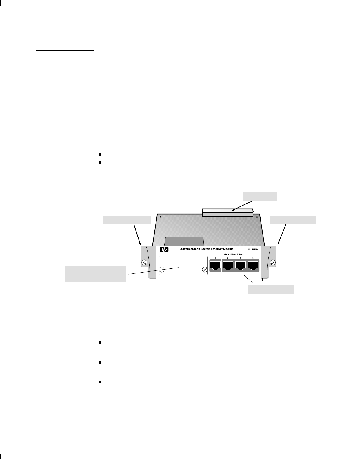
The HP AdvanceStack Switch Ethernet Module (HP J3102A) is an optional
component that you can add to an HP AdvanceStack Switch 2000 to provide
either of the following:
Four 10Base-T ports
Three 10Base-T ports and one (optional) 802.3-compatible transceiver port for other media types (such as ThinLAN, or fiber-optic)
For information on transceiver types and availability, contact your
Hewlett-Packard networking representative.
Connector
Extractor Handle
Cover Plate Over Slot for
Optional T ransceiver
Figure 1. The HP AdvanceStack Switch Ethernet Module
Features: The HP AdvanceStack Switch Ethernet Module can enhance your Switch 2000 in the following ways:
You can use the module to connect different 802.3 media types to
your Switch 2000.
You can add, change, or remove a module without shutting down the
entire switch.
You can install up to six Ethernet modules in your Switch 2000,
enabling you to ‘‘fully load’’ the switch with up to 24
Ethernet/IEEE 802.3 ports.
Extractor Handle
10Base-T Ports
iii
Page 7

Page 8

Contents
Overview . . . . . . . . . . . . . . . . . . . . . . . . . . . . . . . . . . 1
Installing a Module in an Unused Slot . . . . . . . . . . . . . . . . 2
Customizing the Port Configuration . . . . . . . . . . . . . . . . . 8
Rebooting the Switch . . . . . . . . . . . . . . . . . . . . . . . . . 9
Removing or Replacing a Module . . . . . . . . . . . . . . . . . . 10
Adding, Replacing, or Removing a Transceiver . . . . . . . . . . . 12
T roubleshooting . . . . . . . . . . . . . . . . . . . . . . . . . . . . . . 14
Customer Support Services . . . . . . . . . . . . . . . . . . . . . . . 14
Specifications . . . . . . . . . . . . . . . . . . . . . . . . . . . . . . . 15
Physical . . . . . . . . . . . . . . . . . . . . . . . . . . . . . . . . . 15
Environmental . . . . . . . . . . . . . . . . . . . . . . . . . . . . . 15
Connectors . . . . . . . . . . . . . . . . . . . . . . . . . . . . . . . 15
Electromagnetic . . . . . . . . . . . . . . . . . . . . . . . . . . . . 15
Regulatory Statements . . . . . . . . . . . . . . . . . . . . . . . . . . 16
v
Page 9

vi
Page 10

Installation
Overview
Note Before you install the HP AdvanceStack Switch Ethernet Module into
the Switch 2000, you may want to install an optional HP
802.3-compatible transceiver in the transceiver slot in the module.
(Refer to the instructions you received with the transceiver.)
If a transceiver is installed, it replaces the first 10Base-T port as port 1,
as long as no active network is connected to the built-in RJ-45 port 1. If
the Switch 2000 detects the link beat signal on the built-in RJ-45 port 1, it
automatically selects that connector to use for port 1.
You can install an Ethernet Module into the Switch 2000 in any one of the six
module slots, as follows:
1. Insert the Ethernet Module in a Switch 2000 slot (page 2).
2. Customize the configuration for the module ports (unless the default
port configuration is satisfactory for your network application - see
page 8).
3. Reboot the switch (page 9).
Other, optional proce dures include:
Hot-Swapping one module for another; that is, replacing one module
with another without turning off power to the switch (page 10)
Using the hot-swap process to install a transceiver into a module
that has already been installed in the switch (page 12)
1
Page 11

Installation
Caution Static electricity can severely damage the sensitive electronic
components on the HP AdvanceStack Switch Ethernet Module. When
handling and installing the module in your switch, follow these
procedures to avoid damage from static electricity:
Handle the module by its edges and avoid touching the components
and the circuitry on the board.
Equalize any static charge difference between your body and the
switch by wearing a wrist strap and attaching it to the switch’s metal
body, or by continually touching the switch’s metal body while you
are installing the module.
For proper cooling and reduction of electromagnetic emissions, ensure that
a slot cover (provided with your Switch 2000) is installed on any unused port
or transceiver slot.
Installing a Module in an Unused Slot
This procedure assumes that you have either already installed an optional
transceiver in the module or do not plan to install a transceiver at this time.
(The module operates properly with or without a transceiver installed.)
1. Slide out the blank LED label strip from the label slot corresponding
to the physical slot in which you will install the module. The LED
label strips have a small loop on the left end. Use your fingernail or a
small implement to catch the loop and slide the label to the left and
out of the label slot. Then insert the LED label strip you received
with the Ethernet Module. For example, if you are going to install the
module in slot ‘‘A’’, you would replace the blank LED label strip in
label slot ‘‘A’’ with the new LED label strip for the Ethernet Module.
(Refer to Figure 1, on the next page.)
Save the blank LED label strip in case you ever want to remove the
module and its LED label strip.
2. Using a Torx T-10 or slotted screw driver, unscrew the screws in the
cover plate over the slot you want to use, and remove the cover.
Store the cover plate with its screws for possible future use. For
example, to install a module in slot A, see Figure 1.
2
Page 12

Installation
Replace the blank LED label strip
with the Ethernet LED label strip
Figure 1. Remove the Cover Plate from an Unused Switch Port
3. Holding the module by its edges—taking care not to touch the metal
connectors—position the module in front of an open slot on the
switch by aligning the edges of the module with the small grooves
near the bottom of the module slot, as shown in the next illustration.
LED Label Slot ‘‘A’’ Module Slot ‘‘A’’
Unscrew These Two Screws
Module Slot ‘‘B’’
Extractor
Handle
Figure 2. Extractor Handles in the Open Position
4. Make sure the extractor handles on each side of the module are in
the open position (rotated away from the face plate), then push the
module into the slot until you feel the extractor handles contact the
switch chassis. (The handles will move slightly upwards when they
contact the chassis.)
Extractor
Handle
3
Page 13

Installation
5. Seat the module in the slot by simultaneously pushing in on both
extractor handles until they are firmly seated against the front panel
of the module (in the closed position).
Extractor
Handle
Figure 3. Extractor Handles in the Closed Position
If the switch has power during module installation, the LEDs will behave as described below. (If you have not already done so, install the
LED label strip as described in step 1.)
Slot Fault LEDSelf-Test LED
Extractor
Handle
Figure 4. Self-Test and Fault LEDs
4
Page 14

Slot and Port LED Behavior
Installation
LED Pattern
Slot Fault
(for the slot in which
you are installing the
module)
1 FLASHING RAPIDLY if the module is not properly seated
2 ON for less than 1 second after the module has been
properly seated
3 OFF during normal switching operation
4 Flashing slowly if there is a self-test failure.
Check the switch event log through the console interface
for more information.
Note: If the Fault LED for the module slot continues flashing
rapidly, the module may not be completely seated in the slot.
Ensure that the handles on the module are fully in the
“closed” position and the screws in the handles are
tightened.
If the module slot Fault LED continues flashing, unscrew the
screws, open the handles, remove the module, and re-install
it. If the Fault LED continues flashing, remove the module
and contact your HP-authorized LAN dealer or HP
networking support representative.
If a module is not installed properly, and the module slot
Fault LED continues rapid flashing, normal switch operation
halts until the module is removed or properly installed (the
other modules in the switch do continue to forward packets
normally).
Self-test
(for the Switch 2000)
1 ON for up to 40 seconds after the module has
been properly seated
2 OFF during normal switching operation
3 FLASHING simultaneously with slot Fault LED if the slot
has failed self-test. Check the event log by selecting "Event
Log" from the switch’s console in the Main Menu.
5
Page 15

Installation
6. Tighten the captured screw in each handle by using a flat-blade or
Torx-10 screwdriver. Be careful not to overtighten the screws.
Tighten These Two Screws
Figure 5. Securing the Module in the Slot
7. Connect the appropriate network cables to the module’s 10Base-T
ports (and to the optional transceiver, if installed).
Figure 6. Connecting a Cable
Note Use either the built-in RJ-45 connector or a transceiver for port 1—both
will not work simultaneously. The active port 1 connector is
automatically selected based on the following conditions:
If a cable carrying a link beat signal is connected to the first built-in
RJ-45 port on the module, then that port is the active port 1,
regardless of whether there is a transceiver installed.
If no link beat is detected on the first built-in RJ-45 port on the
module, then a transceiver, if ins talle d, become s the active port 1.
6
Page 16

Installation
Note MDI-X Operation: The four 10Base-T ports built into the module are
designed for MDI-X operation (that is, for connecting end nodes to the
switch). Thus, if you connect any of these ports to an MDI-X port on
another device, use a ‘‘crossover’’ cable. But if the connection is to an
MDI port, use a ‘‘straight-through’’ cable.
MDI Operation: An optional twisted-pair transceiver in the transceiver
slot operates in MDI mode (that is, for connecting hubs or other
switches to the Switch 2000). In this case, use a ‘‘straight-through’’ cable
to connect the transceiver to an MDI-X port on another device, or a
‘‘cross-over cable’’ to connect the transceiver to another transceiver or
other MDI port on another device. See the Connectivity Quick
Reference that is included with your module for more information on
connecting the module to network devices.
For more on straight-through and crossover cables, see appendix A,
‘‘Cables and Connectors’’, in the HP AdvanceStack Switch 2000
Installation Guide that is shipped with the Switch 2000.
8. Check the port LEDs for the newly-installed module to ensure that
the port(s) connected in the preceding step are up. (If you have not
already done so, install the LED label strip as described in step 1.)
The “port-enabled’’ LED (1, 2, 3, 4) will be lit for each port that is up.
The transmit (Tx) and/or receive (Rx) LEDs for each port that is
transmitting and/or receiving packets will flash when traffic is
detected on the port.
Full-Duplex LED (Lit When Port Is
Transmit LED
Port-Enabled LED
Receive LED
Tx
1
Dx 2
Rx
Configured for Full Duplex)
Tx
Dx
Rx
Tx
3
Dx 4
Rx
Figure 7. Port LEDs for the Switch Ethernet Module
Tx
Dx
Rx
7
Page 17

Installation
9. Customize the port configuration, if necessary. (See “Customizing the
Port Configuration”, below.)
10. Reboot the switch, since this is a new module being installed. (See
“Rebooting the Switch” on page 9 for more information on when the
switch must be rebooted.)
Customizing the Port Configuration
If the slot in which you installed the Switch Ethernet Module was empty the
last time the switch was either rebooted or reset (or the power to the switch
was cycled), then the module will use preconfigured default parameter
values that will work for most networks.
The default 10Base-T port configuration is:
Enabled: Yes
Mode: Half Duplex
(Full Duplex can be set on any of the built-in RJ-45 ports, but not a
transceiver that is installed and used as port 1.)
T runk (port trunking): None
Broadcast Limit: 0
If necessary, configure the port(s) in the module by using the switch console
interface. (See the Console User’s Guide—HP part number
5964-4644—shipped with the Switch 2000, and the online Help provided in
the console interface itself.)
If the default port configuration, shown above, is correct for your network,
then skip this process.
8
Page 18

Installation
Rebooting the Switch
You can reboot the switch by using the Reboot Switch command in the
console Main menu, or by pressing the recessed Reset button located to the
right of the Power LED.
Reset Button
Figure 8. Location of the Reset Button
Generally, you only need to reboot the switch when it needs to recognize a
change in its hardware or software (console) configuration. Some
circumstances under which you will need to reboot the switch are:
Adding new modules or moving modules to unused slots (page 2)
Installing a module in a slot that was previously occupied by a
different type of module (for example, installing a 100VG module in
a slot that was previously used for an Ethernet module—page 10)
Changing certain switch configuration parameters through the
console interface—in this case, the console provides messages
indicating when the switch must be rebooted for the configuration
change to be activated
You do not need to reboot the switch when:
Replacing a module with the same type of module, or moving a
module to a slot that was previously occupied by the same type of
module (page 10)
Adding or changing a transceiver in the switch module—in this case,
you must remove the module from the switch, and when it is
reinstalled, the switch recognizes the transceiver change (page 12)
9
Page 19

Installation
Removing or Replacing a Module
Use this section to do either of the following:
Replace one module with another
Remove a module without replacing it
Loosen These Two Screws
Figure 9. Removing the Module from the Slot
1. Remove any network cables from the ports on the module.
2. Loosen the screws in the extractor handles of the module you want
to remove from the switch. (Refer to figure 5 on page 6.)
3. Simultaneously pull both extractor handles toward you until the
module releases from the slot and the Fault and status LEDs for that
slot are off.
Note During removal (or installation) the module and switch connectors will
momentarily be only partially connected. The fault LED for the slot
flashes rapidly to indicate this state, and normal switch operation is
temporarily suspended until the module connector is completely
separated from the switch connector. The other switch modules do
continue to forward packets, though.
4. Slide the module out of the slot.
10
Page 20

Installation
5. Do one of the following:
• If you will be installing another module in the slot, go to ‘‘Install-
ing a Module in an Unused Slot’’ on page 2 and begin with step 3.
Make sure that you install the proper LED strip for the new
module you are installing, as described in step 1 on page 2. If
you do not install the correct LED strip for the module you have
installed, the LED display will be incorrect for that module.
• If you will not install another module in the slot (that is, leave it
empty), then re-attach a slot cover plate over the empty slot opening, and replace the LED strip for that slot with a blank LED strip.
6. If you are removing a module, or replacing a module with a different
type (for example, replacing an Ethernet module with a 100VG
module), then reboot the switch as described under “Rebooting the
Switch” on page 9.
Caution For proper cooling and reduction of electromagnetic emissions, ensure
that a slot cover (provided with your Switch 2000) is installed on any
unused port or transceiver slot.
11
Page 21

Installation
Adding, Replacing, or Removing a Transceiver
Caution When adding, removing, or replacing a transceiver from a module,
always remove the module from the Switch 2000 first. Otherwise, you
might interrupt proper switch operation and/or damage the module or
transceiver circuitry.
For proper cooling and for reduction of electromagnetic emissions,
ensure that a slot cover (provided with your Switch 2000) is installed on
any unused port or transceiver slot.
1. Disconnect any network cables attached to the module for which
you will add, replace, or remove a transceiver.
2. Remove the module from the Switch 2000.
a. Loosen the screws in the extractor handles of the module.
Loosen These Two Screws
Figure 10. Removing the Module from the Slot
b. Simultaneously pull both extractor handles toward you until the
module releases from the slot and the Fault and status LEDs for
that slot are off.
c. Slide the module out of the slot.
12
Page 22

3. Do one of the following:
• If you are adding a transceiver: Loosen the captured screws
on the cover plate over the transceiver slot until they disengage
from the module, then remove the cover plate and store it for possible future use.
• If you are removing a previously installed transceiver:
1) Use a flat-bladed or Torx T-10 screwdriver to loosen the
spring-loaded retaining screws on the transceiver bulkhead.
2) Slide the transceiver out of the module and place it in an antistatic container for protection from electrostatic discharge
(ESD).
4. Do one of the following:
• If you are adding a new transceiver or replacing one transceiver with another:
Installation
1) Use the instructions provided with the transceiver to install it
in the module.
2) Re-Install the module in the Switch 2000 using the instructions
under ‘‘Ins talling a Module in an Unused Slot’’ on page 2 and
begin with step 3.
• If you are removing a transceiver without replacing it with
another transceiver:
1) Use a flat-bladed or Torx T-10 screwdriver to install an HP
10Base-T transceiver cover plate over the transceiver slot in
the module.
2) Re-Install the module in the Switch 2000 using the instructions
under ‘‘Ins talling a Module in an Unused Slot’’ on page 2 and
begin with step 3.
13
Page 23

Installation
Troubleshooting
The primary tools for troubleshooting the Switch Ethernet Module are the
LEDs on the front of the Switch 2000. Refer to ‘ ‘Slot and Port LED Behavior’’
on page 5. Also, refer to the installation guide shipped with the Switch 2000,
for more detailed troubleshooting information.
Customer Support Services
Hewlett-Packard offers support 24 hours a day, seven days a week through
the use of automated electronic services including:
Hewlett-Packard BBS and World Wide Web
Hewlett-Packard FTP Library Service on the Internet
CompuServ
HP Network Phone-In Support (NPS)
HP FIRST FAX Retrieval Service
14
Page 24

Installation
Specifications
Physical
Dimensions
Width: 16.5 cm (6.5 in)
Depth: 25.0 cm (9.9 in)
Height: 4.3 cm (1.7 in)
Weight: 0.62 lbs (0.28 kilos)
Environmental
Operating temperature: 0°C to 55°C (32°F to 131°)
Relative humidity: 15% to 95% at 40°C (104°F) non-condensing
Maximum altitude: 4.6 km (15,000 feet)
Connectors
The RJ-45 twisted-pair ports are compatible with the IEEE 802.3 Type
10Base-T standard.
Electromagnetic
Emissions
FCC part 15 Class A
CISPR-22 (1985) Class A EN55022 (1988) Class A
VCCI Class 1
Complies with Canadian EMC Class A requirements.
Immunity
See the Declaration of Conformity in the installation guide for the HP J3100A
AdvanceStack Switch 2000.
15
Page 25

Installation
Regulatory Statements
FCC Statement (U.S.A.)
This equipment has been tested and found to comply with the limits for a
Class A digital device, pursuant to Part 15 of the FCC Rules. These limits are
designed to provide reasonable protection against harmful interference
when the equipment is operated in a commercial environment. This
equipment generates, uses, and can radiate radio frequency energy and, if
not installed and used in accordance with the instruction manual, may cause
harmful interference to radio communications.
This device complies with part 15 of the FCC Rules. Operation is subject to
the following two conditions: (1) This device may not cause harmful
interference, and (2) this device must accept any interference received,
including interference that may cause undesired operation.
VCCI Class 1 (Japan)
16
Page 26

Installation
European Community
This equipment complies with CISPR22/EN55022 Class A.
Note This is a class A product. In a domestic environment this product may
cause radio interference in which case the user may be required to take
adequate measures.
Declaration of Conformity
This product is designed for operation with the J3100A HP AdvanceStack
Switch 2000 and is listed in the Declaration of Conformity included in the
HP AdvanceStack Switch 2000 Installation Guide.
DOC Statement (Canada)
Complies with Canadian EMC Class A requirements.
17
Page 27

Technical information in this
document is subject to
change without notice.
©Copyright 1996
Hewlett-Packard Company
Printed in USA 9/96
Manual Part Number
5966-5118
*5966-5118*
 Loading...