

Page 1

Table of Contents
Agilent Technologies Test & Measurement Catalog 2001
1 Introduction, Indexes & New Products
Agilent Overview 2
Agilent’s Web Site 3
How to Use This Catalog 4
Subject Index 6
Product Number Index 26
Complete Test Solutions 36
New Products for 2001 40
2 Support & Services
Quick Selection Guide 68
1
2
3
4
5
6
7
8
9
10
11
12
Support Overview 69
Hardware & Software Support
Services 70
System Integration Services 74
Consulting & Engineering Services 76
Educational Services 77
Channel Partners 79
3 Design & Test Software and Systems
Instrument to Network
Connectivity Initiative 82
Communications EDA Software 84
Test Software 86
MMS Products 90
VXIbus Products 93
System Switches 97
Interface Products 101
Additional Literature 103
4 General Purpose Instruments
Oscilloscopes 106
Oscilloscope Probes & Accessories 124
Modulation Domain Analyzers 132
Electronic Counters 137
Digital Multimeters 145
Data Acquisition & Switching 154
Function Generators &
Waveform Synthesizers 158
DC Electronic Loads 165
Power Supplies 169
AC Source/Analyzers 192
Additional Literature 194
13
5 RF & Microwave Instruments
14
15
16
17
Signal Sources 198
Signal Analyzers 227
Network/Spectrum Analyzers 266
Network Analyzers 271
Power Meters 303
Noise Figure Analyzers 310
Amplifiers 315
RF & Microwave Test Accessories 318
Additional Literature 331
18
19
20
6 RF & Microwave Systems
EMI/EMC Test Systems 334
Antenna & Radar Cross-Section
Measurements 337
Signals Development &
Intercept Solutions 338
Phase Noise Measuring Systems 341
RF & Microwave Measurement
Systems 342
Additional Literature 346
7 Wireless Communications
Instruments & Systems
Overview 348
Digital Microwave Radio Test
Equipment 352
Wireless Mobile & Base Station
Test Sets 353
Cellular/PCS Transmitter &
Receiver Test Equipment 379
Wireless Network Air Interface
Testing 392
Pager Test Equipment 395
Additional Literature 397
8 Wireline Communications
Instruments & Systems
Overview 400
Protocol Analyzers 402
Digital Transmission Testers 404
SONET/SDH Test Sets 410
Field Installation & Maintenance 413
Voice Testing 417
Additional Literature 418
9 Aerospace & Defense
Overview 422
Electronic Warfare, Radar, Weapons
& Satellite Test Solutions 423
Signal Analysis 425
Physical Test 426
10 Digital Systems Debug, Verification &
Characterization
Characterization Tools & Solutions 430
Verification Tools & Solutions 440
Logic Analysis & Emulation Solutions 442
Additional Literature 463
11 Lightwave Instruments
Optical Component Test 466
Spectrum Analyzers 472
Optical Wavelength Meters 473
CD Test Solutions &
Polarization Analyzers 474
Digital Communication Analyzers 475
Lightwave Converters &
Signal Analyzers 477
Component Analyzers 478
Additional Literature 480
12 Component Test Instruments
Overview 482
Impedance Measuring Instruments 485
Materials Test Equipment 491
LCR & Resistance Meters 494
Additional Literature 501
13 Frequency & Time Standards
Frequency & Time Standards 504
Additional Literature 508
14 Cable & Broadcast Television
Test Equipment
Digital Video Test Equipment 510
Regulatory Test Equipment 513
Maintenance Test Equipment 515
Broadcast TV Analyzers 516
15 Electronic Manufacturing Test Systems
Board Test & Inspection Systems 518
Functional Test 519
Semiconductor Test Systems 520
Semiconductor Measurement
Instruments 523
Data Storage Test Systems 526
Additional Literature 528
16 Mechanical & Physical Test
Instruments and Systems
Data Acquisition Systems 530
Additional Literature 536
17 Laser Interferometers/Encoders &
Laser-based Calibration Systems
Laser Interferometers/Encoders &
Laser-based Calibration Systems 538
Additional Literature 544
18 Rack Solutions & Accessories
Cabinets & Cabinet Accessories 546
Operating & Transit Cases 552
Cables & Adapters 554
19 Purchasing Alternatives
Refurbished Equipment,
Trade Up, Leasing & Finance 558
20 Quotations, Warranties & Local
Assistance
Quotations, Warranties and
Terms of Sale 562
Local Assistance & Sales Offices 563
21 Agilent Publications & Handbooks
Free Application Notes 576
Free Test & Measurement
Specialty Catalogs 599
Free T&M Quarterly Newsletters 602
Technical Handbooks Available
Through McGraw-Hill 603
Call Centers 604
21
Use our test and measurement resources and services often!
www.agilent.com/find/tmc
Page 2

Agilent Technologies: An Overview
Agilent Technologies’ Test & Measurement Organization
2
1
About This Catalog
The Agilent Technologies 2001 Test
and Measurement catalog brings you
a tremendous range of high quality
technology products, as well as many
advances in measurement and test
technology that provide optimized
solutions. This includes the basic tools
of test and measurement, all the way
to complete systems that focus on
emerging electronic and communications fields. For over sixty years we
have developed products and services
that are unequaled in their ability to
help you improve your engineering
results and contribute to your business and personal success.
In response to your comments and
suggestions, we’ve restructured the
catalog to make it easier for you to
find the information that you need.
See pages 4 and 5 for an overview of
how to use the catalog.
New Products
The “New Product” section (pages
40–64) highlights some of our most
recent product introductions, such as
these exciting developments:
• 16702B Logic Analysis Mainframe
• 54600 Oscilloscope Series
• E4991A Impedance/Material Analyzer
• 89600 Series Vector Signal Analyzer
• E8356A Series Network Analyzers
• Omni/BER 725 Communications
Performance Analyzers
• TestExec SL Software Platform
Support and Services
We continue to increase our technical support, resources and professional services to help you get the
most from your Agilent Technologies
experience. See Chapter 2 (page 67)
for a comprehensive description of
“Total Support.” For special needs or
situations requiring customized test
and measurement solutions, our professional consultants can help you
make the right selection.
Total Commitment to Quality
We are dedicated to providing quality
products and services that meet your
changing needs. Agilent Technologies
employees uphold high standards for
performance, reliability and service.
The standards set by our Quality
Maturity System (QMS) exceed the
intent of ISO 9000, the international
standards for quality management
and quality assurance.
Nearly all Agilent Technologies
divisions and calibration laboratories
worldwide are ISO 9000 registered,
which requires periodic audits by
independent experts. Selected
laboratories are accredited to the
high standards of ISO Guide 25. The
integrity ensured by these periodic
audits enables many customers to
augment their own internal quality
systems without the expense of hiring
audit teams. We include an ISO 9000
compliant calibration certificate with
almost every new instrument to make
it easier for you to put your Agilent
equipment into service immediately.
Agilent Technologies Web Site
We expand our World Wide Web site
(www.agilent.com/find/tmc) to meet
your requests for more information
about Agilent Technologies products
and services. We encourage you to
visit the site, where you can obtain
updated technical information and
download application notes, interac-
tive selection guides and free
demonstration software. The site
gives you quick access to the latest
news and training course schedules. See page 3 for our guide to
on-line information services.
Connectivity and Standards
To meet your needs for connectivity between instruments, systems,
and networks, we design our products to fit into locally and publicly
connected domains by using interfaces with industry standard and
often computer standard protocols.
For your convenience, we have
identified these products with special symbols denoting their capabilities. See page 5 for information
about these instrument functions.
In addition, Agilent is a significant
contributor to the development of
open industry standards on
instrument connectivity with such
activities as the IVI (Interchangeable Virtual Instrument) Foundation, as well as developing product
capabilities, such as our connectivity software, that is described in
detail on pages 82 and 83. Agilent’s
connectivity software allows
instruments to communicate conveniently with computers and networks using the skills you already
have, and minimizing the need to
learn new applications. We are certain you will be interested in learning more about this next step in
“user friendliness” and find that it
is in keeping with Agilent’s focus
on helping you use your time to
make measurements rather than
learning how to use the instrument.
Page 3
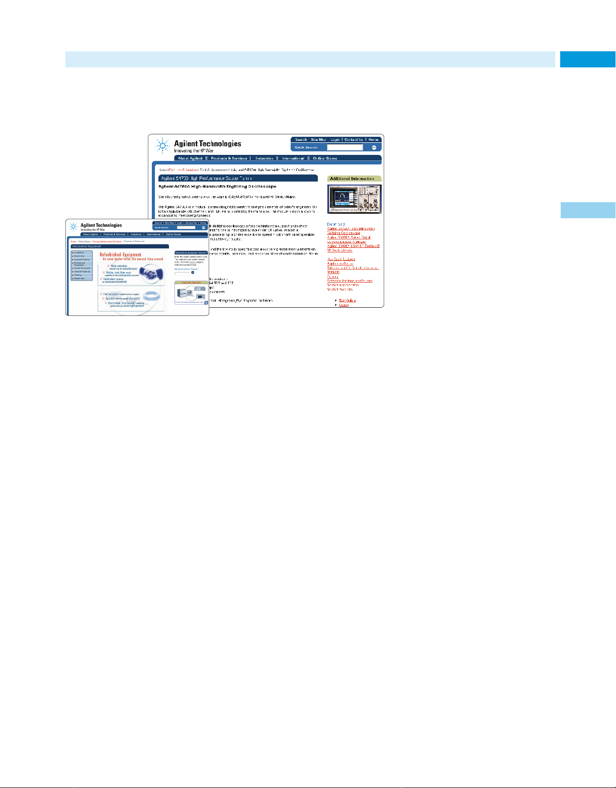
Agilent’s Site on the World Wide Web
Guide to Online Business and Information Services
Find test and measurement information and transact
business on the Agilent Technologies web site
Helpful navigation aids
Buttons on the web page let you
activate key functions or jump between
major areas of the web site:
• Click on the Search or Quick Search
button to quickly find specific
information.
• Press the Library button to access
the industry’s most extensive range
of application notes (printed and
interactive)‚ tutorials‚ technical
papers‚ and many other helpful
documents.
• Press the Technical Support button
to access online help‚ software and
drivers‚ frequently asked questions‚
Take advantage of the vast and expanding range of information‚ support‚ and
business resources‚ and services available at Agilent’s redesigned web site.
The Agilent Technologies web site
has been significantly redesigned and
reorganized to be a more convenient‚
more efficient business tool and
information resource. Our improvement process is ongoing. The new
and expanded industry segment and
product pages are easier to browse‚
making your investigations and activities pleasant and productive.
To keep up to date‚ visit often!
The content of our web site constantly
varies as news happens‚ new products
are introduced‚ application notes and
brochures are published and updated‚
product evaluation tools and learning
aids are added‚ sales promotions are
initiated‚ and events are scheduled.
You can keep up to date by browsing
the web site regularly.
Find... Get... Buy...
The test and measurement information on the web site lets you take
immediate action‚ at any time. You
can use it to quickly:
• find‚ evaluate‚ compare‚ and select
the products and services you need
• get updated‚ expert information
for solving application problems
• get information on replacements
for discontinued products
• buy some types of equipment‚
software‚ accessories‚ and parts
online‚ using a credit card.*
The web site also gives you access to
the many support resources Agilent
Technologies provides. For example‚
you can obtain information in your
local language*‚ check the status of
your order‚ and more.
The product information pages provide quick access to overviews of
instruments and systems‚ application
notes‚ technical details‚ frequently
asked questions‚ manuals‚ software‚
and explanations of accessories.
service manuals and notes‚ the
Metrology Forum‚ and much more.
• Use the Log In button to enter
an online environment tailored
to your specific interests.
• Activate the Online Stores button
to place an order for selected
Agilent selected test and
measurement products.*
• Hit the News Releases button to
get the latest news information.
• Click on the Events button to see
trade show and seminar schedules.
• Use the Education button to review
training and education classes and
courses on topics ranging from
test and measurement fundamentals
to advanced problem solving
techniques.
• Click on the Order Information
button to determine the latest
information about your order.
• Activate the About Agilent button
to learn more about the company
and its history.
• Press the Alliances button to learn
more about services and solutions
offered by authorized Agilent
Channel Partner companies.
• Click on the Contact Us button
to find phone‚ fax‚ and e-mail
information for Agilent offices
and call centers.
• Use the International button to visit
online resources in many countries.
3
1
Use our online test and measurement resources and services often!
www.agilent.com/find/tmc
*Availability of this feature may be limited; an expansion program
is ongoing. For best results, view the Agilent web site with
Microsoft’s Internet Explorer browser.
Page 4
Catalog Overview
1
2
3
4
6
7
8
9
10
11
12
13
14
15
16
17
18
19
20
21
5
Introduction, Indexes & New Products
Support & Services
Design & Test Software and Systems
General Purpose Instruments
RF & Microwave Instruments
RF & Microwave Systems
Wireless Communications
Telecom/Datacom
Aerospace &Defense
Digital Systems Debug, Verification & Characterization
Lightwave Instruments
Component Test Instruments
Frequency & Time Standards
Cable & Broadcast Television Test Equipment
Electronic Manufacturing Test Systems
Mechanical & Physical Test
Laser Interferometers/Encoders & Laser-based Calibration Systems
Rack Solutions & Accessories
Purchasing Alternatives
Quotations, Warranties & Local Assistance
Publications and Handbooks
Look for reusable reference tabs following page 608.
Introduction, Indexes & New Products 1
Catalog Overview & New Product Highlights
1
Table ofContents
Agilent Technologies Test & Measurement Catalog 2001
1 Introduction, Indexes & New Products
Agilent Overview 2
Agilent’s Website 3
How To Use This Catalog 4
Subject Index 6
Product Number Index 26
Complete Test Solutions 36
New Products for 2001 40
2 Support & Services
Quick Selection Guide 68
Support Overview 69
Hardware & Software Support
Services 70
System Integration Services 74
Consulting & Engineering Services 76
Educational Services 77
Channel Partners 79
3 Design & Test Software and Systems
Instrument to Network
Connectivity Initiative 82
Communications EDA Software 84
Test Software 86
MMS Products 90
VXIbus Products 93
System Switches 97
Interface Products 101
Additional Literature 103
4 General Purpose Instruments
Oscilloscopes 106
Oscilloscope Probes & Accessories 124
Modulation Domain Analyzers 132
Electronic Counters 137
Digital Multimeters 145
Data Acquisition & Switching 154
Function Generators &
Waveform Synthesizers 158
DC Electronic Loads 165
Power Supplies 169
AC Source/Analyzers 192
Additional Literature 194
5 RF & Microwave Instruments
Signal Sources 198
Signal Analyzers 227
Network/Spectrum Analyzers 266
Network Analyzers 271
Power Meters 303
Noise Figure Meters 310
Amplifiers 315
RF & Microwave Test Accessories 318
Additional Literature 331
6 RF & Microwave Systems
EMI/EMC Test Systems 334
Antenna & Radar Cross-Section Measure-
ments 337
Signals Development &
Intercept Solutions 338
Phase Noise Measuring Systems 341
RF & Microwave Measurement
Systems 342
Additional Literature 346
7 Wireless Communications
Instruments &Systems
Overview 348
Digital Microwave Radio Test
Equipment 352
Wireless Mobile & Base Station
Test Sets 353
Cellular/PCS Transmitter &
Receiver Test Equipment 379
Wireless Network Air Interface
Testing 392
Pager Test Equipment 395
Additional Literature 397
8 Wireline Communications
Instruments & Systems
Overview 400
Protocol Analyzers 402
Digital Transmission Testers 404
SONET/SDH Test Sets 410
Field Installation & Maintenance 413
Voice Testing 417
Additional Literature 418
9 Aerospace & Defense
Overview 422
Electronic Warfare, Radar, Weapons
& Satellite Test Solutions 423
Signal Analysis 425
Physical Test 426
10Digital Systems Debug, Verification &
Characterization
Characterization Tools & Solutions 430
Verification Tools & Solutions 440
Logic Analysis & Emulation Solutions 442
Additional Literature 463
11Lightwave Instruments
Optical Component Test 466
Spectrum Analyzers 472
Optical Wavelength Meters 473
CDTest Solutions &
Polarization Analyzers 474
Digital Communication Analyzers 475
Lightwave Converters &
Signal Analyzers 477
Component Analyzers 478
Additional Literature 480
12Component Test Instruments
Overview 482
Impedance Measuring Instruments 485
Materials Test Equipment 491
LCR & Resistance Meters 494
Additional Literature 501
13Frequency & Time Standards
Frequency & Time Standards 504
Additional Literature 508
14Cable & Broadcast Television
Test Equipment
Digital Video Test Equipment 510
Regulatory Test Equipment 513
Maintenance Test Equipment 515
Broadcast TV Analyzers 516
15Electronic Manufacturing Test Systems
Board Test & Inspection Systems 518
Functional Test 519
Semiconductor Test Systems 520
Semiconductor Measurement
Instruments 523
Data Storage Test Systems 526
Additional Literature 528
16Mechanical & Physical Test
Instruments and Systems
Data Acquisition Systems 530
Additional Literature 536
17Laser Interferometers/Encoders &
Laser-based Calibration Systems
Laser Interferometers/Encoders &
Laser-based Calibration Systems 538
Additional Literature 544
18Rack Solutions & Accessories
Cabinets & Cabinet Accessories 546
Operating &Transit Cases 552
Cables &Adapters 554
19Purchase Alternatives
Refurbished Equipment,
Trade Up. Leasing & Finance 558
20Quotations, Warranties & Local Assis-
tance
Quotations, Warranties and
Terms of Sale 562
Local Assistance & Sales Offices 563
21Agilent Publications & Handbooks
Free Application Notes 576
Free Test & Measurement
Specialty Catalogs 599
Free T&M Quarterly Newsletters 602
Techincal Handbooks Available
Through McGraw-Hill 603
Call Centers 604
1
2
3
4
5
6
7
8
9
10
11
12
13
14
15
16
17
18
19
20
21
21
576 Application Notes Applications Notes—Amplitude Modulation
21
577Audio—Component Test Application Notes
Application Notes
Agilent Technologies has an extensive
library of both hardcopy and on-line
application information. A listing of
test and measurement application
notes begins on this page.
Application Noteshelp solve your
measurement, computation, and
design problems. They offer the benefit of the applications research and
experience of both Agilentcustomers
and Agilentengineers. Some of these
application notes are tutorial, others
describe how-to procedures.
How to Order
To obtain a free copy of any of the
Application Notes listed here and
on the following pages, contact the
Agilent Call Center in your region.
For Outside the U.S. see inside back
cover. Within the United States,
call (800) 452-4844 and provide the
Agilent customer service representative with the nine-digit literature
number for each Application Note
requested. Please limit your orders to
five Application Notes per phone call.
Many of the most current Application
Notes are also down loadable directly
from the Test & Measurement area
of Agilent’s web site:
www.agilent.com/find/apps
3G Solutions
Challenges in developing the deploying
3G systems
5980-1223E
Designing and Testing 3GPP W-CDMA Base
Stations (BS) (AN 1355)
5980-1239E
Designing and Testing 3GPP W-CDMA User
Equipment (UE) (AN 1356)
5980-1238E
Designing and Testing cdma2000 Base Stations
(AN 1357)
5980-1303E
Designing and Testing cdma2000 Mobile
Stations (AN 1358)
5980-1237E
HPSK Spreading for 3G
5968-8438E
Measurements On Digital Modulation
Components Requiring A Complex Stimulus
(AN 1353)
5980-1337E
Performing cdma2000 Measurements Today
5968-5858E
Amplifiers
Complete Analysis of Erbium-Doped Fiber
Amplifiers (AN)
5965-0976E
How to Characterize CATV Amplifiers Effectively
(AN 1288-4)
5965-9434E
Testing Amplifiers and Active Devices with the
Agilent 8510 Network Analyzer
55963-2352E
Amplifier Measurements Using the Scalar
Network Analyzer (AN 345-1)
5954-1599
Extending Dynamic Range of Scalar Transmission
Measurements Using the Agilent 8757A,
8756A, or 8755C Scalar Network Analyzers
(AN 327-1)
5953-8882
Noise Figure Measurement Accuracy (AN 57-2)
5952-3706
Practical Noise Figure Measurement and
Analysis for Low-Noise Amplifier Designs
(AN 1354)
5980-1916E
S-Parameter Techniques for Faster, More
Accurate Network Design (AN 95-1)
5952-1130
Amplitude Modulation
Spectrum Analysis AM and FM (AN 150-1)
5954-9130
Audio
Basic Operation & Application Guide Agilent
8904A Operation Made Easy (AN 8904A)
5953-8491
Aviation/Transportation
Agilent TS-5400 Series II Remote Keyless
Entry Application
5968-6080E
Agilent TS-5400 Series II Supplemental Restraint
Systems
5968-6356E
93 TS5400 Series II Antilock Brakes & Traction
Control Application
5968-6079E
VOR/ILS Testing with Agilent 8644A
(AN 8644-2)
5951-6740
Battery Testing
Battery Charging/Discharging (AN 250-2)
5952-4033
Board Test
A Quality Test Demands A Quality Fixture
5965-6624E
Connect Check Backgrounder (AN)
5965-5092E
Vectorless Test Purchaser’s Guide
5965-0805E
CAE
Hierarchical Modeling for Circuit
Characterization (AN 1201-2)
5091-1668E
Practical Noise Figure Measurement
and Analysis for Low-Noise Amplifier
Designs (AN 1354)
5980-1916E
Cable Measurements
Balanced Circuit Measurement with an
Impedance Analyzer/LCR Meter/Network
Analyzer (AN 346-2)
5091-4480E
How to Characterize CATV Amplifiers Effectively
(AN 1288-4)
5965-9434E
Measuring the Characteristic Impedance of
Balanced Cables (AN 339-4)
5950-2918
Calibration
Applying Error Correction to Network Analyzer
Measurements (AN 1287-3)
5965-7709E
Noise, Figure Measurement Accuracy (AN 57-2)
5952-3706
Signal Generator (AN 388)
5952-2019
Compliance Testing
Compliance Testing to the IEC 1000-3-2 and
(EN 61000-3-2) and IEC 1000-3-3
(EN 61000-3-3) Standards (AN 1273)
5964-1917E
Compliance Testing IEC/EN 61000-4-8
(AN 1319)
5968-3730E
Conformance Testing
—
An Essential Part of
SDH Deployment
5965-1020E
Conformance Testing and Essential Part of
SONET Deployment
5965-1432E
Cookbook for EMC Precompliance
Measurements (AN 1328)
5968-3661E
Component Test
A Guideline for Designing External DC Bias
Circuits (AN 346)
5950-2912
ABR Technology Overview and Testing
Challenges
5968-1234E
Accurate and Effective Flash Memory Cell
Evaluation Using the Agilent 4072A
5968-6719E
Accurate and Efficient C-V Measurements
(AN E5250A-3)
5965-5658E
Agilent Technologies ParBERT 81250,
Mux/Demux Application
5968-9695E
Agilent VXI Test System Signal Switching
5968-7234E
Automated Characterization of Microwave VCOs
Using the Agilent 5361A/B Pulse/CW
Microwave Counter (AN 377-2)
5952-7988
Automated Extraction of Semiconductor
Parameters using the Agilent 4155B/4156B
5963-1249E
Automatic Frequency Settling Time
Measurement Speeds Time-to-Market
for RF Designs
5964-4335E
Balanced Circuit Measurement with an
Impedance Analyzer/LCR Meter/Network
Analyzer (AN 346-2)
5091-4480E
Biasing Three-Terminal Devices for Test
(AN 376-1)
5952-4193
Characteristic Impedance Measurement of
PC Board Circuit Patterns Using the Agilent
4194A Impedance/Gain-Phase Analyzer
(AN 339-2)
5950-2908
Characterizing Communications ICs With
The Agilent 83000 Model F660
5962-9273EUS
Characterizing Components with a Microwave
Tracking Source (AN 1212)
5091-2172E
Characterizing High-Speed Optical Transmitters
Compliance Testing with the Agilent 86100A
Infiniium DCS (AN 1340-1)
5968-9249E
Combining Network and Spectrum Analysis and
IBASIC to Improve Device Characterization
and Time Set
5965-7656E
Characterizing Digitally Modulated Signals with
CCDF Curves
5968-6875E
Constant Current Measurements Using the
Agilent 4194A (AN 944-1)
5950-2923
Contact Resistance and Insulation Resistance
Measurements of Electro-mechanical
Components (AN 1305-1)
5968-0325
Effective Electrolytic Capacitors Testing
5967-5378E
Effective Multitap Transformer Testing Using
a Scanner (AN 1239)
5091-6310E
Effective Transformer/LF Coil Testing
(AN 1305-3)
5967-5377E
Efficient Evaluation of LISNs and Voltage Probes
for EMI Tests Using the Agilent 4194A
(AN 364-1)
5950-2922
Evaluating Chip Inductors Using the Agilent
4291B
5966-1848
Evaluation of Flash Memory Cells (AN 4156-4)
5965-5657E
Evaluation of Hot Carrier Induced Degradation
of MOSFET Devices (AN 4156-3)
5963-1111E
Filter Test for Production and Incoming
Inspection
—
Agilent 4194A Impedance
Gain-Phase Analyzer (AN 339-11)
5952-7887
Many of these documents are orderable and downloadable from Agilent’s web site:
www.agilent.com/find/apps
Free Application Information
8
419Telecom/Datacom (cont.) Additional Literature and Product Notes
ATM/Broadband Test Systems
1993 B-ISDN Seminar Handbook Primer
5962-8794E
1994 B-ISDN Seminar Handbook Primer
5962-0011E
1995 Broadband Communications Map
5963-9489E
BSTS Product Ordering Guide
5964-0393E
Conformance and Interlop Testing
—
What You Must Know
5965-1457E
Broadband Series Test System Product Information
5966-0035E
Implementing ATM Signalling Solution Note
5963-7514E
MPEG-2 Digital Video Technology
Solution Note
5963-7511E
Traffic Policing Solution Note
5963-7510E
WAN Interworking with ATM Solution Note
5963-7512E
E4829B Product Overview
5964-1667E
E4829B Technical Data Sheet
5963-9923E
Ease Your Network’s Migration to ATM
Brochure
5965-4968E
ATM Testing and LAN Connectivity
Measurements Under One Handle
Brochure
5966-3293E
E5200A Broadband Service Analyzer
Technical Data
5965-1376E
Broadband Service Analysis–Coping with the
Network Test Challenge White Paper
5965-1377E
OmniBER 717 (37717C) Brochure
5964-5817E
OmniBER 717 (37717C) Technical Specifications
5968-3132
(PN E4200, 10, 17A) NNI Signalling Test Software
Helps Ensure Seamless ATM Networks
5965-6307E
(PN) Proceedings of the 1995 B-ISDN/ATM
Protocol Testing Seminar (E4200B, E4210B)
5964-3579E
(PN E4821A, E4829B, E4885A) Implementation
of UTOPIA Level 2 for Parallel Cell/Traffic
Generator and Analyzer
5965-4856E
(PN E4829B) Cell Transfer Time Measurement
Using the Parallel Cell/Traffic Generator
and Analyzer
5965-5297E
(PN E482xA/B, E4889A) Real Time Bit
Error Rate Analysis at Parallel Interfaces
(UTOPIA) with E4829B
5965-4855E
(PN E4505A-2) Test Sequences for More
Effective Testing of SDH and ATM
5965-4911E
(PN E4505A-2, 37717B/C) Interactive Diagnosis
For More Effective Support of SDH and
ATM Networks
5965-4912E
(PN OmniBER 717) Physical Layer Jitter Testing
in an ATMEnvironment
5965-4861E
Field Installation & Maintenance
Power Meter Sub-module E6007A and
Visual Fault Finder Sub-module E6007A,
Photo Card
5966-0022E
Multimode OTDR Modules E6005A, E6009A,
Photo Card
5966-0023E
E6053A, E6058A, E6060A Rack OTDR
Photocard
5966-4227E
ODTR Family Accessories Photocard
5966-4878E
Many of these literature pieces are available at:
www.agilent.com/find/tmc
8
418 Additional Literature and Product Notes Telecom/Datacom
Protocol Analyzers
3 Dimensional Network Testing AC
5963-1054EN/EUS
Announcing New Multiprong Testing Brochure
5091-7635E
Frame Relay Message Sets Technical
Specifications
5963-0085EN/EUS
Frame Relay Test Software Technical
Specifications
5963-6653EN/EUS
Frame Relay/SMDS Seminar Book
Solution Note
5963-9501E
Group 4 Fax Testing Product Note
5091-2002E
Integrated FR Testing with PT502 Data Brief
5091-2003E
Integrated SMDS Testing with PT502 Data Brief
5091-2006E
ISDN Primary Rate Testing Solution Note
5963-2013EN/EUS
ISDN Testing Data Brief
5091-2141E
Executable Test Suites for PT Series
Technical Specifications
5963-1090EN
Protocol Testing at Bank of Montreal
Solution Note
5962-9750EN/EUS
PT Series Technical Specs
Technical Specifications
5963-0082E
V3.0 Test Software Technical Specifications
5963-0086EN/EUS
X.25 Protocol Testing Tech Data
Technical Specifications
5962-8746EN/EUS
X.25/X.32/X.75 Testing with PTs Brochure
5091-7847E
Intuitive Signaling Analysis for Fixed and
Wireless Networks
5968-2796E
Digital Transmission Testers
NIU Quick Isolation of DS3 Network Problems
5965-8345E
3-Slot and 12-Slot Equipment Shelves for
E4586A DS3 NIU
5963-7141EUS
E485XA Serial Cell Generator and Analyzer
5963-9924A
37722/32A Brochure
5965-3192E
37722/32A Configuration Guide
5965-3194E
37722/32A Technical Specifications
5965-3193E
E4540A DNA Software Brochure
5964-2240E
71603B Brochure
5965-1431E
T1 Test Advisor Testing Just Got Easier Brochure
5967-6060E
E1 Test Advisor Brochure
5967-6161E
HDSL Installer’s Assistant Brochure
5965-8937E
71612B Brochure
5968-2810E
General Purpose Instruments Catalog
5968-8736EUS/EN
(PN E4540A) Automated Test Sequences
for More Effective Testing of SDH and
ATM Networks
5965-4911E
(PN E4540E) Interactive Diagnosis for
More Effective Support of SDH and
ATM Networks
5965-4912E
(PN 71612B) Locating Errors in Gigabit
Transmission Systems and Components
5968-2811E
(PN 71612B) Extending Hi-Speed BERTesting
to 20 Gb/s
5964-6133E
(PN 71612B) Testing 10 GB/s SONET/SDH
Equipment and Components
5968-2812E
Error Performance Analyzers
86130A BitAlyzer—Should a Bit Error
Ratio measurement be hard to make?
We don’t think so. (Brochure)
5968-8547E
86130A BitAlyzer Error Performance Analyzer
Technical Specifications
5968-8545E
86130A BitAlyzer 3.6 Gbit/s Error Performance
Analyzer Product Demonstration
5968-9432E
86130A BitAlyzer Enhanced Error Analysis
Options Product Overview
5980-0913E
SONET/SDH Test Sets
E4480A CERJAC 156 MTS Brochure
5966-2243E
E4480A 156 MTS Technical Data
5963-2178EUS
E4487A CERJAC Series 31XE Technical Data
5964-2463EUS
37718A Product Note
5968-2041E
37719A Brochure
5968-0761E
(PN E4480A/87A and E4595) Enhanced,
Easy-to-Use SONET and T-Carrier Testing
5965-3650E
(PN E4480A/87A) Graphical Control,
Measurement and Analysis
5965-3648E
(PN OmniBER 718) PDH Digital Radio Test
5965-4885E
(PN OmniBER 718) Tributary Jitter Testing
of SDH Network Equipment Using
ITU-T G.783 Pointer Sequences
5965-4862E
(PN OmniBER 718) Automatic Verification
of Network Equipment to ITU-T Jitter
Tolerance Recommendations
5965-4863E
(PN OmniBER 718) Resolve Finger-Pointing
Problems on 140 Mb/s Transport Signals
5965-4886E
((PN OmniBER) Professional Measurement
Results Report
—
At Your Fingertips
5968-2041E
(PN OmniBER) STM-16c/OC-48c Concatenated
Payloads: Essential for Testing DWDM and
Broadband Systems
5968-2040E
(PN OmniBER) Verifying Protection
Switching Mechanisms in Linear
and Ring Topology Networks
5965-9915E
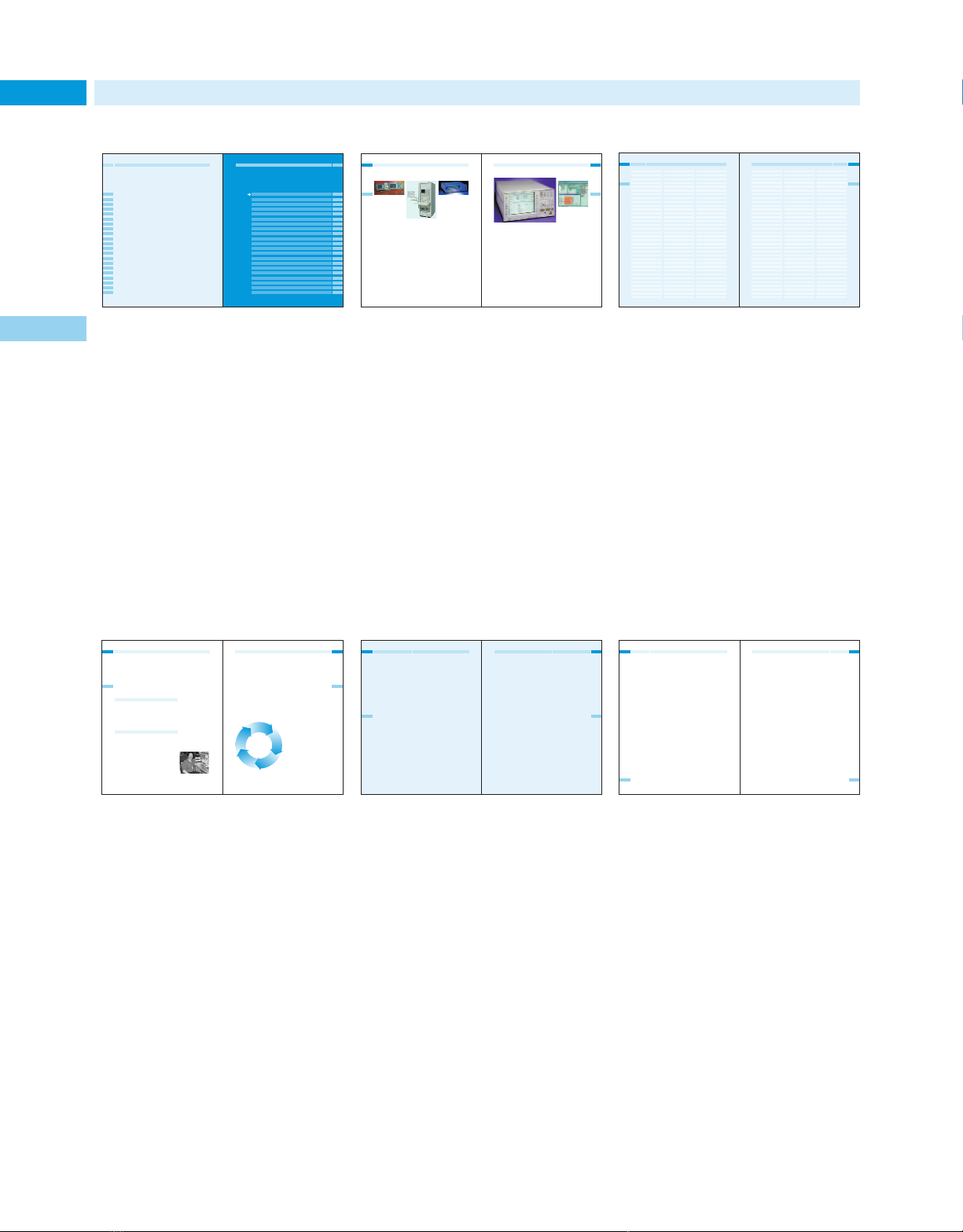
4 How to Use This Catalog
Table of Contents
Easily find the major section of pro-
1
ducts or systems that you need. Refer
to major sections by the number on
the thumb tabs. Major sections and
subsections are listed throughout the
contents by page number. The contents of each major section and additional references are repeated for
you on the first page of each section.
See page 1.
New Products for 2001
Test IS-2000 mobile phones
A single-format version of the 8960
test set is available for early-tomarket IS-2000 mobile phone manufacturing test. The IS-2000 test mode
application provides IS-2000 testing
without call processing using mobile
phone test modes. This single-format
8960 test set will be upgradeable to
multi-format capability when IS-2000
call processing functionality is introduced mid year.
The test set’s format-flexible architecture is designed to grow with 3G
mobile phone technologies. Agilent
has designed the 8960 series 10 test
set to meet the needs of mobile
manufacturers now and into the
future. As mobile phone technology
advances, new formats will be added
and the hardware will be upgraded.
For more information, see page 363.
For detailed specifications, circle 29 on the
reply card (last page) or call the Agilent
Test & Measurement Call Center at
1-800-452-4844. Ask for QuickCode 7221.
New Products for 2001
Manufacturing Test
Test executive software
improves manufacturing
test productivity
The software offers rapid test system
development and a fast, simple-to-use
execution environment.
The Agilent E2011E TestExec SL
software platform helps test engineers improve their productivity. It
provides valuable usability tools that
enable them to spend less time writing software and more time running
tests. The software also helps manufacturers standardize their functional
testing. They can deploy the proven
E2011E test executive not only plantwide, but globally as well.
The TestExec SL software supports
the most popular test development
environments, including C/C++,
Visual Basic, Basic for Windows,
LabVIEW, LabWindows/CVI and
VEE. Usability tools such as the
Action Wizard, Test Profiler, and
Switch Manager aid system configuration and make it easier to optimize
system performance. The Throughput
Multiplier enables the system to test
multiple devices simultaneously
without the need to add hardware
or write custom software.
For more information, see page 86.
For detailed specifications, circle 30 on the
reply card (last page) or call the Agilent
Test & Measurement Call Center at
1-800-452-4844. Ask for QuickCode 7222.
New Products for 2001
Lightwave/Component Test
54
Simplify the characterization of lightwave
components and systems
1
The DWDM channel analysis function
provides accurate power, noise, and
channel-wavelength measurements.
The performance capabilities, features
and built-in measurement applications of Agilent 86140B-family optical
spectrum analyzers (OSAs) simplify
the time-consuming tasks of characterizing optical components and systems. Each OSA includes a wavelength division multiplexing (WDM)
application with the patented dualsweep measurement technique, which
is the quickest way to measure and
record channel power, wavelength,
and optical signal-to-noise ratio.
Available in benchtop and portable
platforms, these OSAs have a remotecontrol capability for automated test
applications. They produce tabular
displays of channel wavelength,
power, OSNR, gain tilt, and peak-topeak power deviation. The data can
be viewed on the display, printed on
the built-in printer, or saved as CSV
files on the internal floppy drive.
One of the OSAs, the 86141B, has a
monchromator output and a power
meter function. The monchromator
output lets you isolate a single channel from a WDM signal or perform
other filter functions. The power
meter lets you maximize power
transfer in applications such as fiber
alignment, or make quick measurements of broadband optical power.
For more information, please see page 53.4
For detailed specifications, circle 26 on the
reply card (last page) or call the Agilent
Test & Measurement Call Center at
1-800-452-4844. Ask for QuickCode 7218.
Accurately characterize
40-Gb/s optical
components
The 50-GHz lightwave component analyzer
characterizes the 40-Gb/s components
being developed for OC-768 applications.
Lightwave transmission systems
require accurate, repeatable characterization of their components to
guarantee high-speed performance.
The Agilent 86030A 50-GHz lightwave component analyzer accurately
and reliably characterizes the 40Gb/s components being developed
for OC-768 applications. The analyzer
measures the bandwidth of optical
receivers, and photodiodes. It can
also determine the bandwidth or
reflection of O/E (optical/electrical),
E/O, O/O, and E/E devices in magnitude and/or phase.
The 86030A lightwave component
analyzer uses a factory characterized
and calibrated internal O/E receiver
to provide calibrated measurements
of optical components. This lets
you verify that the devices you
design and manufacture meet
industry standards.
For more information, see page 478
For detailed specifications, circle 27 on the
reply card (last page) or call the Agilent
Test & Measurement Call Center at
1-800-452-4844. Ask for QuickCode 7219.
High-throughput capacitance meter for production environments
The capacitance meter enables higher
test throughput, while providing high
measurement accuracy.
The Agilent Technologies 4288A 1-kHz/
1-MHz capacitance meter is an optimum solution for high-speed production testing of the ceramic capacitors.
The meter offers improved measurement speed and accuracy with no
decrease in test efficiency. Several
features ease handler system integration: a built-in comparator that
sorts the measurement results into a
maximum of nine bins, an optoisolated handler interface, a GPIB
interface, and more.
For measurement systems that use a
component scanner, the capacitance
meter offers the optional scanner
compensation function. Error compensation can be performed independently for each scanner channel. This
minimizes not only the measurement
error in each channel, but also inconsistencies and the error in measured
values between channels.
For more information, see page 498
For detailed specifications, circle 28 on the
reply card (last page) or call the Agilent
Test & Measurement Call Center at
1-800-452-4844. Ask for QuickCode 7220.
Multi-format mobile manufacturing test set helps you
meet your production goals
This wireless communications test set provides a competitive edge in high-volume,
automated mobile phone manufacturing test.
In high-volume mobile manufacturing,
test throughput and test yield are the
keys to meeting production output
goals. The Agilent Technologies 8960
Series10wireless communications test
set offers manufacturers immediate
competitive advantages. Developed for
high-volume, automated mobile phone
manufacturing test, the proven 8960
Series 10 offers speed, accuracy,
repeatability, multi-format capability,
ease of programming, and all in a format-flexiblearchitecture. These features can help lowertest costs and
raise production outputs.
The 8960 Series 10 test set can be
configured for GSM, GPRS, TIA/EIA136, and AMPS mobile phone testing.
IS-2000 mobile phone test with
multi-format capability will be added
mid year. Multi-format test capability
allows manufacturers to test multiformat phones with a singletest set,
change production from one format
to another to meet changing demand,
or manufacture mobile phones with
different formats on the same line.
For the manufacturer, this means
faster response to market changes,
less downtime for changeovers, and
improved test set utilization.
Agilent Technologies introduces hundreds of new products each year.
This full-color section features 48 new
products for 2001 from Agilent’s Test
& Measurement Organization. These
exciting and innovative new products reflect Agilent’s commitment
to research and development investments. They also illustrate major technology and market trends. See page 40.
Indexes
Subject Index
8 Subject Index AAL – Analyzers
55
1
RF and microwave 299-310, 602
A
AAL-2, 5 388
AC
Power source/analyzers 181-182
Power sources, portable 181, 244
Source/analyzers 181-182
1
AC/DC current probe (oscilloscope) 124
Access loop test 392, 396, 518
Accessories
Adapters
1.0 mm 50, 285
APC-3.5 557-558
APC-7 557-558
For network analyzer 271, 284
For timing generator 448
General 555-559
Overview/ordering information 557-558
Wedge probe adapter 122, 432-433
Alligator clip leads 484
Attenuators 304-307
Attenuators/switch drivers 299
BNC kits 278
Cable TV analyzer 513-514
Cables
50 ohm 448
And adapters 284, 556-558
Antenna 496-497
General 555-559
GPIB interconnection 556
Mating 484
RF 278
Test port 278, 284
Couplers, coaxial 310
Delay line, 22ns 117
Detectors, coaxial 308-309
Digital multimeters 146-147
EMC analyzer 316-317
Frequency and time standards 497
GPS antenna 497
High-power pulse generator 447
Impedance/gain-phase analyzer 467
LCR meters 481-482
Lightwave 462
Logic analyzers 432-433
Multimeters 146-147
Network analyzers
Microwave network analyzers 281, 285
System accessories 265, 268
Vector voltmeter and input modules 282
Noise figure and scalar measurements 240
Oscilloscope 113-114, 117
Power splitters 276, 278
Probes 118-124
AC/DC current probe 124
Active 123-124, 244, 258
Current 124, 147, 317
Elastomeric 432-433
For fine-pitch ICs 122, 432
High frequency 244, 276
Kelvin 147
Locator base solutions 432-433
Optional accessories for 433
Passive 118-120, 124
Surface-mount device 122, 147
Temperature 147
Quad clip
Additional literature 312
Coaxial detectors 308-309
Coaxial fixed attenuators 307
Coaxial single- and dual-directional couplers,
90u hybrid coupler 310
Coaxial step attenuators 305-306
Custom switch interfaces 299
High-performance programmable
step attenuators 304
Switching solutions, coaxial
switches 300-303
RF bridges 276
RF limiter 275, 277
RF network analyzers 270-271, 275-276
Resolution timing generator 448
Scalar network analysis 240
Signal analyzers 240, 291
Spectrum analyzer 244
System accessories, MMS 83, 602
Test fixture 478
Test lead kits 147
Torque wrench 448
Transit cases 278, 281
Transition time converter 448
Type N, SMA 557
Acoustic analysis 536
ACPR (adjacent channel power ratio)
measurement 357
Active
Device modeling 550
Probes 123, 244, 258
Resistive divider 124
ActiveX
Graphic control components 64
Controls/automation 80
Adapters
1/mm 50
APC-3.5 557-558
APC-7 557-558
BNC 557-558
Banana plug 557-558
Cables & cases 555-560
Detector 263
Network analyzer 271, 284, 433
Ordering information 557-558
Overview of 557-558
Probing 122, 432
SMA, Type N 557
SMA/SMB 558
TDMA/CDPD 338
Timing generator 448
Type N 558
Additional literature 96, 105, 183, 311, 328,
370, 400, 449, 465, 486, 499,
506, 527, 538, 546, 579-604
Adjacent Channel Power Ratio
(ACPR) measurement 53, 357
ADSL test 378, 518
Advanced Design System 46, 50, 53, 548
Advanced intelligent network (AIN) 399
Aerospace and defense 403-410
Overview 404
Agile signal generators 189, 218
Agilent Technologies
An Overview 4
Web site 5
Air interface measurements 52, 367-368
Alligator clip leads 484
AM/FM/Pulse signal generators
Agile signal generator 189
Digital I/Q modulation 194
Economy RF signal generators 190, 194
High-performance RF signal
generators 201, 203, 205
Microwave signal generators 206
Modulation 188, 194, 201, 216
Signal sources to 110KHz 188
Synthesized swept signal and
CW generator family 212-213
VXI microwave synthesizer 48, 208-209
Amplified lightwave converters/
receivers 117, 462
Amplified wide bandwidth lightwave
converter 462
Amplifiers 296-298
50/60 Hz to 400 Hz 181-182
Application Notes 579
Distribution 492-493
Fiber-optic distribution 501
Line497
Microwave 296-298
Modulation 212, 216
Modules, VXI 84
Preamplifiers 244, 317
RF 244, 296
Test 522-524
VXIbus 87
Amplitude
Flatness 333
Modulation application notes 579
AMPS test solutions 52, 331
Analog
Multiple output power supplies 169
Power supplies 175
Analysis Probes 427-428
Analyzers
Audio 364-365
Broadcast TV 516
Cable TV, FFT dynamic signal 513-515
Communications performance 58, 386
Digital video signal 511
Distortion 364-365
Dynamic signal 537
EMC/EMI 48, 314
FFT dynamic signal 536, 604
Impedance 45, 254-258, 474
Jitter 83, 128, 376, 387
Logic 63
Modulation 125-129, 247
Network 44, 46, 254-287, 374, 587
Protocol 55, 372, 374-375
S-parameter test sets 260, 269, 275, 279, 283
Signal 83, 219-254, 320, 356-361
Signal component 464
Special test sets 275
Spectrum 47, 82-83, 219-257, 458, 470
State and timing analysis 414-434
Telecom/Datacom 376
Vector
Network 44, 46, 270
Signal 249-250, 252, 262, 362
WDM channel 459
Wide bandwidth 249
Anechoic chamber application notes 579
Angular/linear encoder systems 544-545
Antenna & radar cross-section
measurements 318
Antenna test 318
Antennas
Biconical 317
Conical log spiral 317
GPS496-497, 501, 505
Measurement software & systems 318
Positioner encoder 318
APCR 49
Application notes 579-601
Applications consulting 74
Arbitrary
Software 155
Waveform generators 152, 155, 218
ARCNET networks, testing 373
ARM, Processor Interface Probe 414, 416
ASP 58
Asset management 68
ATE
Electronic loads 157-159
Multiple output power supplies 169
Power supplies 175
Test systems 42, 48, 76, 352, 399, 517-527
ATM
AAL-2 testing 388
ATM/B-ISDN, test systems for 389
Analysis 388
Broadband test systems
Communications performance analyzer 390
Modular 0-622 Mb/s ATM/
B-ISDN testing 388-389
Communications performance analyzers 386
HP LAN Analyzer 374
Interfaces, jitter tolerance of 390
MPEG transmission tester 389
Protocol tester 388-389
Signaling stack, solutions for 388
Stream processor 58, 388
Switch funtional/performance benchmarking 58
Switch/network testing 388
Test instruments 387-390
Transmission and protocol testing 388
ATM/IP broadband test systems 388-390
ATSC, real-time digital video test platform for 512
Attenuators
Accessories 304-307
Coaxial 305-307
High-performance programmable step 304
Interconnect kits 305
Measurement systems architecture 299
Optical 455, 457
Switch drivers 299
Upgrade kits 271-272
Audio
Analyzers 219-221, 364-365
Application notes 579
aurora series testers 379
Automated
Optical inspection 518
Test equipment 42, 48, 76, 352, 399, 517-527
Verification and emulation 399
Automatic drift routine 459
Automotive solutions 94-95
Autoranging power supplies 175
Available Bit Rate (ABR) 388
Aviation/transportation application notes 579
Avionics testing equipment 181-182, 403-410
AwareTest xi software linkage 65
B
B-ISDN protocol model test 390
Balanced output, function synthesizer 153
Base station
CDMA PCS 340-341, 355
Connection kits 338
Emulator 218
Maintenance 339
Test set 334, 337, 350-351
Baseband
Signal analyzers 319-321
Vector signal analyzers 250, 252, 511
Vector waveform generators 218
BASIC (HP Instrument) 537
Basic Instruments catalog 604
Battery testing
Application notes 579
Electronic loads 157-159
Bench power supplies 160
BenchLink software
BenchLink Arb 155
BenchLink Data Logger 148
BenchLink Meter 139
BenchLink Scope 108
BenchLink Spectrum Analyzer225, 229-230, 236
Bias
Current source/text fixtures 481
Multiple output power supplies 169
Biconical antenna 317
Bit error rate (BER) Tester 49, 58, 376, 385-387,
Bluetooth signal analyzer 250-251, 253, 362
BNC
Accessory kits 278
Cables 272
Board test
And inspection systems 40, 65, 518, 527
Application notes 579
Books, technical 606
Boundary scan 518
Bridges, RF 244, 264, 272, 276, 278
Broadband
Control system measurements 537
Light source 461
Series Test System (BSTS) 55, 58, 388-389, 604
Service analyzer 389, 537
System sweep/Ingress analyzer 515
Broadcast TV test equipment 509-516
BSTS 55, 58, 388
Burst
Carrier trigger 244
Signal analysis, vector signal
analysis 250, 252, 511
Burst-mode data, error performance
analysis of 440
Bus analyzer 435-436
There are two indexes in this catalog.
The Subject Index references product
categories, key terms, applications, and
other useful information. See page 6
The Product Number Index allows
you to find Agilent products if you
already know their product numbers.
All new products for 2001 are identified. Page numbers in bold type indicate the main references for that
product. See page 27.
Analyzers – Calibration Subject Index
C
C meter (capacitance) 483, 521
C-V meter 469
C-V plotter (semiconductor testing) 521
Cable TV
Accessories 513-514
Analyzer 221, 250, 513-514
Digital video 508-509
MPEG analyzer 512
Maintenance Test Equipment 515
Measurement personality 231, 513
Monitor personality 231
Spectrum analyzer 219
Sweep/Ingress Analyzer 515
Test equipment 221, 231, 508-515
Cable and broadcast television test
equipment 507-516
Broadcast TV analyzers 516
Digital video test equipment 509
Overview of 508
Cable measurements application notes 579
Cable test 269
Cables
And adapters 556-558
Antennas 497
APC-7 278
BNC 272
GPIB interconnection 556
IEEE 1284-compliant 556
Interconnect 278, 304-305, 484, 556
Mating 484
Network analyzer 265
RF 305
Test port 278, 284
Type-N 272, 276, 278
CAE
Application notes 579
Simulation and modeling tools 46, 50, 548-549
438, 525-526
Simulation link 362
Calibration
Application Notes 579
Electronic calibration modules 281
Electronic calibration (Ecal) 279, 281
Instruments 71
Interface 338
Kits 270-271, 277-278
Laser-based machine tool calibration
Measuring receiver 245
Multiple output power supplies 169
Network analyzer 271
Noise figure meter corrections 293
On-wafer 286
Phase noise measurements 323
Power meter 290
RF cable 278
RF impedance 258
S-parameter 258
Services 70-71
System
Transmission/reflection test 258, 268
Upgrade
system 540-546
Accessories 264
Cable 265
Machine tool 543
9
1
Support & Services
Support Overview Support Overview
68 Quick Selection Guide
Agilent support services: How can we help?
Whether you need a fast answer about equipment operation or a factory full
of custom test systems, Agilent’s service and support team is ready to help.
We’ve built a comprehensive set of services with one goal in mind: giving you
the tools and information you need to succeed on the job, no matter what
your job may be.
Contacting Agilent for support
The Agilent T&M web site is a growing source of online support information,
available 24 hours a day, 7 day a week. We recommend you start there. If you
do not find your answer, click on “Assistance” to find the easiest way to contact Agilentfor help.
Web: www.tmo.agilent.com
No access to the web? In the US:
Phone: 1-800-452-4844
For fax and email, request a form by calling 1-800-452-4844.
For all other locations, please refer to page 604 for your nearest Agilentoffice.
Our Promise: Delivering on expectations
We want your Agilentequipment to deliver the performance you expect. If
you need assistance, we provide a range of support from verifying proper
operation to clarifying information in the manuals.
Our Promise Page 69
Our web site: www.tmo.agilent.com, offers
extensive information:
• Online operating manuals
• Product features and specifications
• Product and application notes
•FAQs
• Service notes
• Catalog requests
Your Advantage: The power of choice
If you want additional services, Your Advantage provides a selection of
engineering, repair and support services to help you through the entire
life cycle of your test systems:
Your Advantage Page 69
Hardware repair and calibration Page 70
Software support Page 70
On-site support Page 71
Application consulting Page 76
Productivity consulting Page 76
Education and training Page 77
Agilentrefurbished instruments Page 552
Test system design and integration Page 74
Channel Partners Page 79
Agilent Technologies is the
“
standard in terms of service
that I measure every other
company against.
That’s how Jim Giordano, a test
engineer with Ethicon Endo-Surgery
sums up his experience with Agilent
service and support. “The number
one reason we keep coming back to
Agilentis the quality of the postsales support. Agilentservice adds
tremendous value to the product.”
Resolution in hours, not months
Jim recently played phone tag with
one vendor for two months trying to
get their equipment to work as
advertised. With Agilent, his expectations are on the order of hours.
“An Agilentengineer even paged me
on my way home from work one
evening because he knew I needed
an answer in a hurry. I called him
back when I reached home, and we
solved the problem that night.”
A superior solution: products
plus people
“With Agilent, the combination of
superior product design and superior customer service means that I can
count on my equipment to provide
nearly 100% up-time, making measurements that I havenever had to
question, with expert technical support people who help me make the
most of the equipment capabilities in
my applications. I consider Agilentto
be a dotted-line member of every
team I work on.”
Jim Giordano, Ethicon Endo-Surgery
This section provides you with an
overview of the wide range of
consulting and support services
available through Agilent’s Test &
Measurement Organization. Agilent
offers services and consulting for all
phases of your test and measurement
solution life cycle. See page 68
”
Total support coverage for the life of your equipment
Our service and support promise is
Our Promise
S
I
N
O
G
O
T
H
C
Q
E
U
T
I
P
H
M
G
I
Z
I
M
I
X
A
M
Y
ON
When you’re ready to choose new
equipment, we’ll help you with:
•Product information, including
realistic performance specifications
•Product recommendations from
experienced test engineers
When you use Agilentequipment,
we’ll make sure your equipment performs as promised, at no extra
charge. Here’swhat you can expect:
•Operation verification to ensure
your equipment is working properly
•Help with product operation
•Basic measurement assistance to
help with specified capabilities
•Extensive self-help tools
We also have global instrument warranties by Agilent, worldwide.
H
E
E
N
T
G
R
E
U
T
N
T
NI
I
N
N
G
G
U
Q
P
U
A
I
C
N
K
D
L
Y
N
R
U
ET
T
R
N
E
E
H
T
M
G
T
N
I
ES
V
N
I
R
U
O
Supporting excellence in engineering throughout
the lifecycle of your test system.
Your Advantage
Every application scenario is unique,
so we offer a flexible set of services.
You can purchase the services to fit
your unique needs during every
phase of ownership.
Agilentinstrument or a worldwide
network of test systems, our engineering, repair and calibration services will keep you running at peak
performance. By taking advantage of
our consulting and design services,
your team can focus on core tasks
while we take care of the instrumentation. As with all our services, you
select as much as or little as you
need to fit your technical and financial requirements.
to help at every phase of the system
life cycle, from planning and design
through installation, integration and
operation. By applying these services
in whatever way meets your unique
needs, you’ll achieve the full benefits
of Agilentservice and support:
•Reach peak productivity sooner
•Maximize the return on your
investment
•Enjoy dependable measurement
accuracy for the life of your system
simple: maximize value, minimize
risk and eliminate headaches. We
work to fulfill this promise in three
ways:
You get what you paid for.
Our Promise means your equipment
will meet its advertised performance
and functionality.
You get the support you need.
From presales advice through equipmentdisposal, Agilentengineers and
technicians deliver the most comprehensive support in the industry.
Support is available for at least five
years beyond the production life of
every Agilentinstrument.
Support costs are distributed fairly.
Delivering world-class support
costs money; that’s a fact of life.
Your Advantage is an easy way to
optimize your results by choosing
from a menu of services that provide
as much or as little as you need.
R
G
N
I
C
A
T
L
N
P
E
E
R
R
PM
O
UI
G
Q
N
E
I
R
D
U
A
R
O
G
Y
P
U
E
Y
N
OU
H
A
R
N
E
C
Q
I
N
U
G
I
P
M
E
N
T
Internet URL www.agilent.com/find/tmc Product & Order Info 8am-8pm EST 1-800-452-4844
Whether you own a single
Our test specialists are ready
Additional Literature
& Product Notes
69Our Promise and Your Advantage
22
Agilent has published considerable
additional information on the instruments noted at the end of most sections of the catalog. This includes
focused data sheets, brochures and
catalogs. In addition, Product Notes,
written for specific instruments, are
available on request. You may obtain
this literature from our web site:
www.agilent.com/find/tmc, or use our
convenient reply card in the back.
Application Notes
The 2001 Catalog contains a comprehensive listing of Application
Notes, all of which are available
to you free of charge. See page 576.
This literature covers topics such
as impedance, modulation, and
semiconductors, and provides information to help you solve many test
and measurement problems. A list
of Application Notes is also available from our web site:
www.agilent.com/find/tmc
Page 5
8662A
8663A
High-Performance RF Signal Generators
Signal Sources
8662A/8663A Synthesized Signal Generators 1
Spectral purity is the key contribution of both the Agilent 8662A and
8663A, making them ideal for many radar, satellite communication,
and phase noise measurement applications. Typical absolute phase
noise performance of these generators at a 1 kHz offset is as low as
–135 dBc/Hz, depending on the band of operation.
The frequency range of the 8662A is 10 kHz to 1280 MHz. It
offers versatile AM/FM, using either internal 400 Hz and 1 kHz rates
or externally applied modulating signals which can be either ac- or
dc-coupled. It also has simultaneous modulation capability.
The 8663A and 8662A provide the U.S. Air Force MATE
(Modular Automatic Test Equipment) capability, via Option 700.
This option is an external translator that allows the signal generator
to be controlled by the MATE language CIIL (Control Interface
Intermediate Language).
8662A Specifications
Frequency
Range: 10 kHz to 1280 MHz (1279.9999998 MHz)
Resolution: 0.1 Hz (0.2 Hz above 640 MHz)
Accuracy and Stability: Same as reference oscillator
Internal Reference Oscillator: 10 MHz quartz oscillator. Aging rate
< 5 x 10
–10
/day after 10-day warmup (typically 24 hrs. in normal
operating environment).
Spectral Purity
Front-Panel Absolute SSB Phase Noise (dBc/Hz):
Frequency range (MHz)
0.01 to 119.91120 to 159.92160 to 319.9
2
Spec Typ Spec Typ Spec Typ
1 Hz – 68 – 78 – 66 – 76 – 60 – 70
10 Hz – 98 – 108 – 96 – 106 – 90 – 100
100 Hz – 116 – 126 – 115 – 125 – 109 – 119
1 kHz – 126 – 132 – 129 – 135 – 124 – 130
3 kHz – 126 – 135 – 129 – 138 – 124 – 133
5 kHz – 128 – 138 – 131 – 141 – 126 – 136
10 kHz – 132 – 138 – 142 – 148 – 136 – 142
100 kHz – 132 – 139 – 142 – 148 – 136 – 142
Frequency range (MHz)
320 to 639.92640 to 1279.931280 to 2559.9
4
Spec Typ Spec Typ Spec Typ
1 Hz – 54 – 64 – 48 – 58 – 42 – 52
10 Hz – 84 – 94 – 78 – 88 – 72 – 82
100 Hz – 103 – 114 – 97 – 108 – 92 – 102
1 kHz – 118 – 125 – 112 – 119 – 106 – 113
3 kHz – 118 – 127 – 112 – 121 – 106 – 115
5 kHz – 120 – 130 – 114 – 124 – 108 – 118
10 kHz – 131 – 136 – 124 – 130 – 118 – 124
100 kHz – 131 – 136 – 124 – 130 – 118 – 124
Residual SSB Phase Noise (dBc/Hz):
Frequency range (MHz)
0.01 to 119.91120 to 159.92160 to 319.9
2
Spec Typ Spec Typ Spec Typ
10 Hz – 108 – 114 – 112 – 119 – 106 – 113
100 Hz – 121 – 126 – 122 – 129 – 118 – 124
1 kHz – 128 – 133 – 131 – 138 – 127 – 134
3 kHz – 128 – 136 – 131 – 139 – 127 – 135
5 kHz – 129 – 138 – 133 – 141 – 129 – 136
10 kHz – 132 – 137 – 142 – 147 – 136 – 142
100 kHz – 132 – 137 – 142 – 147 – 136 – 142
Frequency range (MHz)
320 to 639.92640 to 1279.931.28 to 2559.9
4
Spec Typ Spec Typ Spec Typ
10 Hz – 100 – 107 – 93 – 101 – 88 – 95
100 Hz – 112 – 119 – 105 – 112 – 100 – 106
1 kHz – 121 – 128 – 115 – 122 – 109 – 116
3 kHz – 121 – 129 – 115 – 123 – 109 – 117
5 kHz – 123 – 130 – 117 – 124 – 111 – 118
10 kHz – 131 – 136 – 124 – 130 – 118 – 124
100 kHz – 131 – 136 – 124 – 130 – 118 – 124
1
8663A band begins at 0.1 MHz; specifications extend up to and including 119.9999999 MHz.
2
Specifications extend up to and including 0.1 Hz less than the starting frequency
of the next band.
3
Specifications extend up to and including 1279.9999998 MHz.
4
This band available on 8663A only; specifications extend up to and including
2559.9999996 MHz.
Option 003 Specified SSB Phase Noise for Rear-Panel 640 MHz Output:
Spec Typ
1 Hz – 54 –64
10 Hz – 84 –94
100 Hz – 104 –114
1 kHz – 121 –126
3 kHz – 121 –127
5 kHz – 129 –138
10 kHz – 145 –149
100 kHz – 157 – 159
SSB Broadband Noise Floor in 1 Hz BW at 3 MHz Offset From Carrier:
<–146 dBc for fc between 120 and 640 MHz at output levels
above +10 dBm.
• 10 kHz to 1280 MHz frequency range
• <–147 dBc/Hz SSB phase noise at 10 kHz offset
• 0.1 Hz frequency resolution
• 100 kHz to 2560 MHz frequency range
• AM/FM/ M/pulse in one generator
• Internal variable modulation oscillator
8662A 8663A
5
Internet URL www.agilent.com/find/tmc Product & Order Info 8am-8pm EST 1-800-452-4844
211
Product Descriptions
E
F
H
Symbols
4
The QuickShip symbol, used in the
ordering information, indicates
specific products available for quick
delivery. To order QuickShip items,
call 1-800-829-4444.
Outside the U.S. contact your local
call center or sales office to order
products available through QuickShip.
B
G
3
This symbol identifies all new products for 2001 throughout the general
products and systems pages.
1
This symbol is used throughout the
catalog and identifies products that
have GPIB (IEEE-488) capability.
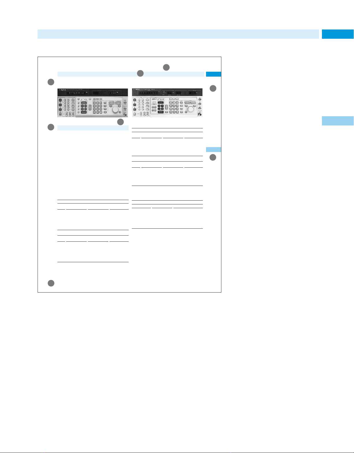
5How to Use Product Descriptions
The body of this catalog contains over
A
10,000 new and existing test and measurement products and accessories from
Agilent. Although not every Agilent
product is included, you will find all
C
relevant references to other sources.
A General product headline
Identifies the broad product
category of the instrument,
system or service described
in the section.
1
B Product description
Defines the specific purpose
and function for the product
described.
D
C Product number
Defines the specific Agilent
model numbers and versions
that are described on the page.
D Section tab number
Relates to the Section numbers
identified in the Table of
Contents, and defines a
product family.
E Product features
Give an “at-a-glance” view of
the key features of the products
on the page.
F Specific product identification
Defines the features and
specifications of one model
in the family of products
on the page.
G Product attribute marks
Define, by symbols described
below, which special features
or services apply to this product.
H Agilent action and help locations
5
This symbol identifies products that
include an Agilent interface for simplified FTP and NFS LAN/WAN remote
access and control via an X11 window
display. This Agilent networked user
interface adds instrumentation
resources to client-server computing
systems and increases the capability
of existing network connections.
Page 6

Subject Index
6 Subject Index ac power sources – Amplitude modulation
A
ac power sources
Analyzers 192-193
Portable 254
ACPR (Adjacent Channel Power Ratio)
measurement 383
ADS (Advanced Design System) 59, 84, 260
ADSL (Asymmetrical Digital
Subscriber Line) 408-409, 518
AM/FM
Agile signal generator 199
1
Digital I/Q modulation, ESG-D/DP series
digital RF signal generators 205-208
Economy RF signal generators 200-204
High-performance RF signal generators 209-213
Microwave signal generators 214
Modulation 198, 210, 223-224
ESG-A/AP series analog
RF signal generators 202-204
ESG-D/DP series digital
RF signal generators 205-208
Source modules 225
Pulse signal generators 198-224
Signal sources to 110KHz
Synthesized swept signal and
CW generator family 221-222
VXI microwave synthesizer 216, 218
AM/FM/Phase signal generators 199, 211-213
AM/FM/Pulse-Modulation
signal generators 199, 217
AM/PM/FM demodulation 260
AMPS
Mobile phone test 363, 365, 367
Test solutions 43, 55, 350, 363, 365, 367
ARCNET networks, testing 401
ARM
Motorola 442
Processor debug 444
ATE
Electronic loads 165-168
Multiple output power supplies 179
Power supplies 185
Simulation subsystem 218
ATM
Additional literature and product notes 419
Advisor LAN analyzer, and 402
Analysis 408
Communications performance analyzers 411
Access loop test 413, 518
Accessories
Adapters
APC-3.5 555-556
APC-7 555-556
For network analyzer 285
For timing generator 439
Wedge probe adapter 128, 460-461
Alligator clip leads 499
Antennas 336
Attenuators/Switch drivers 318, 324-327
Cable TV analyzer 513-514
Cables
50 ohm 439
Adapters, and 554-556
GPIB interconnection 554
Mating 499
Couplers, coaxial 330
Delay line, 22ns 123
Detectors, coaxial 328-329
Digital multimeters 152-153
EMC analyzer 336
High-power pulse generator 438
LCR meters 496-497
Lightwave 477
Logic analyzers 460-461
Multimeters 152-153
Network analyzers 292-294, 284-285
Noise figure and scalar measurements 250
Oscilloscope 124-131
Preamplifiers 336
Probes
Active 130, 254, 270
Current 131, 153, 336
Differential 61
Elastomeric 460-461
For fine-pitch ICs 128, 460
High bandwidth 61
High frequency 254
High voltage 131
Kelvin 153
Locator base solutions 460-461
Optional accessories for 461
Passive 124-126, 131
Resistor divider 131
Scope 61, 124-131
Surface-mount device 153
Surface-mount probing accessories 128
Temperature 153
RF & microwave
Additional literature 332, 599
Coaxial detectors 328-329
Coaxial fixed attenuators 327
Coaxial single- and dual-directional
couplers, 90µ hybrid coupler 330
Coaxial step attenuators 325-326
Custom switch interfaces 318
High-performance programmable
step attenuators 324
Switching solutions,
coaxial switches 320-323
RF network analyzers 284-285
Resolution timing generator 439
Scalar network analysis 250
Signal analyzers 250
Spectrum analyzer 254
Switching solutions 319
Test
Fixture 493
Lead kits 153
Torque wrench 439
Transit cases 293
Transition time converter 439
Type N, SMA 555
Active probes 130, 254, 270
ActiveX controls/automation 87
Adapters
APC-3.5 555-556
APC-7 555-556
BNC 555-556
Banana plug 555-556
Detector 277
Kits 302
Network analyzer 285, 461
Probing 128, 460
SMA, Type N 555
SMA/SMB 556
TDMA/CDPD 357
Timing generator 439
Type N 556
Additional literature
Adjacent channel power
measurement 42, 231, 242
Advanced design system 59, 84
Advisor testers 402
Aerospace & defense products 421-426, 441
Agile signal generator 199, 223-224
Agilent Technologies
Application notes, free 576-598
CaLan 513
Call centers 604-605
Channel Partners 79, 459
Communicating with 562
Financing 66, 68
Overview 2
Signal Studio 218
Specialty catalogs 599-601
Support options 68
T&M quarterly newsletter 602
Web site 3
Alligator clip leads 499
Amplified
Lightwave converters/receivers 123, 477
Wide bandwidth lightwave converter 477
Amplifier test, RF 520-522
Amplifiers
50/60 Hz to 400 Hz 192-193
Application Notes 576
Distribution 507
RF and Microwave 254, 315-317
Modules, VXI 93
Preamplifiers 254
VXIbus 96
Amplitude flatness test system 352
Amplitude modulation
ESG-A/AP series analog RF signal
generators 202-204
Application notes 576
—
see Literature
Page 7

7Analog – Cabinets & cabinet accessories Subject Index
Analog
RF signal generators 202-204
Signal sources 202-204
Analysis
Logic 63-64, 442-463
Probes 455-458
Analyzers
12 Gb/s BER 406
ac source 192
Audio 390-391
Broadcast TV 516
Cable TV 513-515
Channel 473
Communication performance 51, 411-412
Digital communications 53, 406
Distortion 390-391
EMC/EMI 49, 336
FFT dynamic signal 114, 262-263, 265, 515, 535
Impedance/Material 47, 409, 487-488
Jitter 92, 135, 404, 409, 412
Lightwave component 54, 472, 478
Logic 63-64, 442-463
Modulation 41, 132-136, 257-258
Network 48, 266-302, 402, 584
Noise figure 50, 310-314
Optical spectrum 54, 472
PCI-X 62, 440-441
Polarization 474
Protocol 50, 408-409, 586
Semiconductor parameter 58, 522-523
Signal 92, 204, 227-270, 339, 382-387, 477
Spectrum 49, 91-92, 204, 227-249,
259, 348-351, 472, 484
Telecom/Datacom 404, 408-409
Network 48
Signal 41-42, 259, 262, 264, 388
Time interval 132, 135
Vector signal 41-42, 260-265
WDM channel 473
Anechoic chamber application notes 576
Angular/Linear encoder systems 542-543
Antenna & radar cross-section
measurements 337
Antenna positioner encoder 337
Application notes 576-598
Arbitrary
Source 532
Waveform generators 56, 60, 158-163, 207, 218
Asset management 68
Attenuators
Attenuator/switch drivers 318
Coaxial 325-327
Interconnect kits 325
Lightwave 471
Measurement systems architecture 318
Optical 471
Programmable step 324
Upgrade kits 286
Audio
Analyzers 227-229, 390-391
Application notes 576
aurora testers 408
Automated
Optical inspection 518
Test Executive 86
Test equipment 48, 55-56
Automatic drift routine 473
Automation tools 89
Autoranging power supplies 185
Aviation/transportation application notes 576
Avionics testing equipment,
ac power sources 192-193
B
BASIC
Bundles 101
Instrument 535
Windows, for 87, 89
BER test equipment 51-52, 205-208, 407-409
Balanced
Components 337
Output, function synthesizer 159
Base station
CDMA PCS 359-360, 381
Connection kits 357
Maintenance software 358
Test sets 356-362, 375-376
Baseband
Signal analyzers 338-340
Vector signal analyzers 262, 264, 512
Basis, power supplies 185
Battery testing
Application notes 576
Electronic loads 165-168
Emulation 46, 173
BenchLink software
Arb 161, 163
Data Logger 154
Scope 114
Spectrum Analyzer 240, 246
Benchmarking 396
Bias
Current source/text fixtures 496
Multiple output power supplies 179
BitAlyzer 43, 121, 405-406
Bit error rate (BER)
Analysis 405-407
Test 526-527
Tester 51-53, 404, 406, 412
Bluetooth
Microwave source 46, 217
Signal analyzer 262-265, 388
Board test and inspection systems 518, 528
Application notes 576
Books, technical 603
Boundary scan 518
Bridges, RF 254, 278, 286
Broadband
Control system measurements 515, 535
Series test system 601
Service analyzer 535
Broadcast TV test equipment 516
Burst
Carrier trigger 254
Signal analysis, vector signal
analysis 262, 264, 512
Bus analyzer 62, 440-441
Buying plans for Agilent equipment 66, 558
1
C
C meter (capacitance) 498
C-V meter 483
CAE
Application notes 576
Simulation 59, 84, 388
CATV test equipment 510, 513-514
CD test solutions 474
CD/ROM, ac power source, product for 192-193
CDMA (Code Division Multiple Access)
Air-interface measurement systems 392
Base station test 356-360, 381
cdma2000 41, 43, 45, 379
cdmaOne 233, 379, 381
Cell site testing
Cellular adapter 357-358
Cellular/PCS base station test set 359-360
Channel simulator 384
Digital RF signal generators 389
Drive test 43, 392-394
IS-2000 mobile phone test 363, 366-367
Measurement personalities 205-208,
227, 381-383
Mobile station service test 368-369
PCS base station 359-360
Software 368-369, 371
Spectrum analyzer 227, 262, 381
Test systems 377
Transmitter test 379, 381-383
CDPD cellular adapter 357
CEPT digital circuits 404
CW (Continuous Wave) 198
Frequency measurements 135, 137
Generators 198, 214, 246
Microwave
Counters 138, 141
Signal generators 214, 221
Sensors 308
Signal sources 198, 214
VXI microwave synthesizer 46, 216-218
Cabinets & cabinet accessories 546-551
Page 8

8 Subject Index Cable – Component test
Cable
Measurements application notes 576
Network analyzers
Spectrum analyzer 227
Test equipment 229, 241, 510-514
Television test equipment
Digital video test equipment 510-512
Maintenance test equipment 515
Measurement personality 233, 241, 513
Monitor personality 241
Overview 510
Regulatory test equipment 513-514
1
Testing 283
Cables
Adapters, and 279, 301, 324-325,
477, 499, 554-556
Network analyzer 279, 301
CaLan products 515
Calibration
Application notes 576
Electronic calibration (Ecal) 48, 291, 293, 299
Frequency measurement response 477
Interface 357
Kits 299-300
Laser-based 385, 431
Measuring receiver 255
Mechanical 299-300
Multiple output power supplies 179
On-wafer 297
Phase noise measurements 341
Power meter 307
Services 70
System cable 279
System machine tool 541
Upgrade, network analyzers 279
Verification 256
Calibrators
Laser-based machine tool calibration system 541
Power meter calibrator 307
System accessories 278
Call centers, Agilent 604-605
Call processing test solutions 350
Capacitance meters 54, 498
Cards
Application measurement cards/
personalities 227, 241, 382, 516
Distribution expansion 318
Logic analyzer 449
PCI exerciser and analyzer 440-441
Carrier phase noise analyzers 230
Carts, Testmobile 462
Cases 152, 552-553
Catalogs
General purpose instruments 601
MMS 90
Power products 171, 175
RF and microwave test accessories 318
Test & measurement curriculum 601
Test & measurement products 599-601
Cell site testing
Base station testing 356, 359-360, 381
CDMA 350, 356-357, 381
Dual mode 357
Installation 356
Maintenance 356
Sets 350, 356-358
Software 358, 360
TACS 348, 350-351, 356
TDMA 350, 356-357
Cellular
Network air-interface
measurement system 43, 392
Phone testing solutions 353, 363-367,
377, 379, 397
Radio
Adapter 353, 357
Additional literature 397
Test sets 350, 353, 403
Test systems 377
Telephone & trunked radio testing 354
Cellular/PCS transmitter and
receiver test equipment 350, 379-391
Audio analyzer 390
Digital RF signal generators 206-208
Distortion analyzer 390
Modulation analyzers 257-258
Spectrum
Monitoring and RF coverage
measurement systems 43, 392, 397
RF coverage measurement system 392
Vector signal analyzers, dc to microwave 388
Centronics I/O ports, GPIB converter for 554
Cesium, frequency standard 504
Channel
Analyzers 473
Partners 79
Characterization tools and solutions 430-439
Chirp measurements 477
Chromatic dispersion test solution 474
Circuit
Analysis, PLL 344
Models 84
Testing 404
Clock frequency standards 504, 508
Coaxial
Cable 439
Connector/adapter, performance curves 555
Couplers 330
Detectors 328-329
Directional couplers 330
Fixed attenuators 327
Power sensors 307
Step attenuators 325
Switches 56, 319-323
Thermistor mounts 307
Code
Debugging 442
Domain analysis 42
Domain power (CDP) measurement 361-362
Combination analyzers 482
Communications
ac/dc ring signal generators 192-193
DWDM test solution 410
Design solutions 346
Digital RF signal generators 206-208
EDA software 84-85
Error performance 406
Functional test system 518
Handhelds & portables 408
Installation & maintenance testers 408-409
Mask test kit 118
Network Test & Measurement Handbook 603
Network test solutions 400, 504
Pager test 395
Pattern generation 406
Performance analyzers 51, 411-412
Products, MMS 92
Satellite payload test, RF equipment for 90
Service test solutions 409
Signal generators 200-201, 395
Simulators 352
Transmission analyzer 404
Transmitter test equipment 262, 350, 353,
356, 382-387, 516
Wireless test equipment 41-45, 348-397
Wireline test products 92, 400-418
Compact PCI 440-441
Complete test solutions
Case histories 37-39
Overview 68-69
Complex
Demodulation 260
Signals
Generation, function synthesizer 159
Viewing, modulation domain
analyzers 132, 136
Compliance
Measurements 53
Testing 513-514, 576
Component analysis 478, 489-490, 518
Component test
Battery 489-490
Cable 489-490
Capacitor 487-490
Circuit analysis 487-488
Inductor 487-490
Instruments
Additional literature and product notes 501
Impedance measuring 482, 485-490
LCR and resistance meters 483-484, 494-500
Lightwave optical 478
Materials test applications and
solutions 483, 491-493
Overview 482-484
Page 9

9Component test – Digital Subject Index
Lightwave 54, 472, 478
Memory device 57
Relay 489-490
Resistor 487-488, 490
Resonator 489-490
Semiconductor 489-490
Switch 489-490
Transformer 489-490
Transistor 489-490
VCO 344
Varicap diode 487-490
Computer-aided test 87
Computer-standard technologies 40
Computer-verification tools 440-441
Computers & peripherals application notes 577
Connecting instruments to PCs 82-83
Connectivity software 82-83
Consulting services 68, 76, 90
Consulting services
Engineering 68, 76
Support 67, 77, 98
Containers 552-553
Control system application notes 578
Controllers, VXIbus 93, 95, 101, 471
Converters
50/60 Hz up to 1000 Hz 192-193
Analog to digital 154, 426, 530-535
Downconverter 262, 264
GPIB 554
Lightwave 123, 477
Microwave 256
Optical/Electrical 477
Transition time 439
Counters 137-144
CW microwave 138
High-precision oscillators 137
MMS 91
Microwave and millimeter-wave frequency 137
Microwave counter/power meters 143
Overview 137
Pulse/CW microwave 138, 144
RF 137, 139
Time-interval 137-138
Universal 137-139
Couplers, coaxial 330
Crystals, application notes 578
Current
Measurement 165-168, 173-174, 176-180, 185
Probes 128, 131
Source 176
Custom test sets systems 36-39, 74, 259, 294
D
DBS noise source 312
dc
Consumption current 344
Coupled lightwave converters 477
Electronic loads 165-168, 195
Power supplies 46, 62, 169-192, 353
Source/monitor 525
DCA 121-122, 475
DCCH Test 354
DCS 44, 350
DCS 1800 350
DECT
Measurement personalities 227, 382, 384
Signal generator 205-208, 350
Test set 350
Test solutions chart 350
Transmitter test 350, 382, 384
DMCA radio test personality 388
DMMS test accessories 91, 145, 148, 150, 152-153
DQPSK signal generator 206-208
DRC (design rule checker) 84
DS1/0 408
DS1/DS3 testers 411-412
DS3 test set 412
DSL
ADSL 408
HDSL 408
DSP, design and synthesis 84, 262-263, 265, 549
DVB
QAM Analyzer 510-511
DVMs 143, 145-153, 194
DWDM 52, 54, 410-411, 470
Data
Acquisition 154-157, 426, 530-535, 578
Characterization solutions 431
Communications 348-418, 578
Control 534-535
Converters, application notes 418, 578
Generators 430-432
Modules, jitter 133
Storage test systems 526-527
Systems 530-535
Verification tools 133, 434-436, 438-439
Viewers 530
Datacom/Telecom instruments and systems
Additional literature and product notes 418
DWDM test 410
Digital transmission testers 404, 408-409
Overview 400
Protocol analyzers 402-403
Testers 408-409
Debuggers/Debugging 63
Digital circuits 442
Interactive debugging solution 440
Third-party support 459
Tools 442, 445-447
Deep memory 59
Defense satellite & signal solutions 422-426
Delay
Line 123
Spread 392
Demodulation 252
Design & test software and systems
Additional literature 103
Automation 41, 59, 84
Environments 442
Design guides 59, 84
Detectors
Adapters 277
Bridges, network analyzers and 285-286
Broadband directional 328
Coaxial 328-329
Precision 277
Diagrams eye-contour 406
Dielectric
Constant 483, 492-493
Materials 489
Measurement system software 491-492
Probe kit 293, 491
Test 492-493
Differential
Interferometers 539
Measurement 337
Digital
Analyzers 53, 121-122, 475
Signal sources 205-208
Application notes 578
Characterization solutions 430-439
Communications
Analyzers 53, 121-122, 475-476
Microwave source 46
Data tester 404, 412
Data transmission application notes 579
Design & debug, digital systems 62-64, 429,
442-462, 599
Design & test instruments/systems 430-431,
434-436, 438-439, 442
Additional literature and product notes 463
High-power pulse generator 438
Overview 442
DWDM test 410
IC test equipment & systems 520-523
I/Q microwave synthesizer
Digital RF signal generators 205-208
Modulation 217
Logic analyzers 442-462
Measurement 46, 382, 395
Microwave
Radio test equipment 352
Synthesizer 217
Modulation
Analysis 259
Microwave synthesizer 217
Signal sources 217
Multimeters 91, 145-147, 149-153, 194
Nanovolt/Micro-ohmeter 148
Scanning 154
Temperature/SPRT 148
Pattern generator 63, 453
Radio test equipment 348, 352
Signal analyzers 259
Radio test systems 259, 348, 352
Resolution timing generator 439
RF signal generators 205-208
Signals-to-Source 442
1
Page 10

10 Subject Index Digital – Financing
Systems debug and verification 62-63, 429,
Test sets 410-412
Transmission testers 400, 404, 408-409, 418
Verification tools and solutions 430-431,
Video test equipment 510-512
Voltmeters 143, 145-153, 194
Wireless measurements 348, 350
Digital Communications Analyzer 53, 121-123
Digital systems debug, verification &
characterization 62-63, 428-463
Digitizers 91, 532
1
Digitizing oscilloscopes
General specifications for 121-122, 475
MMS 91
Modules 452
Overview 107
Dimensional measurements, angular/
linear encoder systems 542-543
Directional bridges 254, 278
Directories, test and measurement 599
Disk drive test
Application notes 579
Testing 133
Display, for MMS control 91
Distortion
Analyzers 228, 230, 390-391
Application notes 579
Measurement set 535
Distribution amplifier 507
Dividers, power 330
Doubler, frequency 213
Downconverters 91-92, 262-265, 512
Drift measurement, optical signal 473
Drive test systems 43, 392-393
Driver, attenuator/switch 318
Dual
Banana plug 556
VHF switch 554
Dual-channel
Dynamic signal analyzers 535
Meters 303
Power 303
Power meters 305
Dual-output power supplies 179
Dynamic
Calibrator 541
Data/sequence, FASS use
Measurement 173-174, 177
Signal analyzers 228, 230, 535
E
EAMPS/AMPS test solutions 348, 350-351
ECal 299-300
ECM/ECCM
Application Notes 579
EDA 59, 84
442-463, 599
440-441, 463
EDGE (enhanced data rates for GSM evolution)
Design Library 85
Signal analyzer 262-263, 265
Signal generator personality 206
Vector signal analyzer 379
EE set products 59, 84
EIA racks
EM Design 84
EMI, measurement systems 49, 336
EMI/EMC
Additional literature 332, 346
Analyzer 49, 334-336
Measurement personality 241
Measurement software 335
Receivers 334
Test systems 334
ESG series
A/AP analog RF signal generators 202-204
D/DP digital RF signal generators 205-208, 389
ESG-D/DP series digital RF signal
generators 205-208
ETACS/TACS test solutions 348, 350-351
EVM measurement 42
EW, signal analyzers for 259
EasyRent 558-559
Ec/Io measurement 392
Educational services
Catalog, test/measurement curriculum 601
Customer support services 68, 77-78
Electrical
Length, application notes 579
Test board-level 518
Electroacoustic devices, evaluating 535
Electromechanical engineering
test equipment 531
Electronic
Calibration 48, 299-300
Counters
CW microwave 137-138, 141
Microwave and millimeter-wave
frequency 137
Microwave counters/power meters 141, 143
Modulation domain analyzer applications 134
Overview 137-138
Pulse/CW microwave 138, 144
RF 137, 139
Universal 137-139
Loads 62, 165-168
Manufacturing test systems
Additional literature and
product notes 528-529
Board test and inspection systems 518
Data storage test systems 526-527
Functional test 519
Semiconductor measurement
instruments 523-525
Semiconductor test systems 520-522
Warfare (EW)
Application notes 579
Radar & weapons testing 423
Electronic Instrument Handbook 603
Emulation 456
Application notes 580
Battery 46, 173
Modules 455
Probes 455
Signaling 50, 403
Solutions 442, 455
Encoders
Angular/linear 542-543
Antenna position 337
Laser 538-543
Systems 542-543
Energy detection tools, radio 340
Engineering services 68
Equivalent-circuit analysis function,
component measurements 485
Erbium-Doped Fiber Amplifier (EDFA) test 472
Error
Analysis 580
Application notes 580
Correction 299-300
Detector 12 Gb/s analyzer 406
Location analysis 406
Performance analyzer 92, 406
Ethernet testing, handheld scanners for 401
Excess noise ratio 312
Eye-contour diagrams 406
Eye-diagram analysis 92
Eye-finder technology 64
F
FDDI protocol analyzer 402
FFT
Dynamic signal analysis 114, 262-263, 265, 515
Oscilloscopes 114
FLEX/FLEX-TD test solution 395
FM deviation 344
FSK signal generator 206-208
Fading simulator 350-352
Far-field antenna measurement systems 337
Fault
Finder 416
Location, capabilities 291-292
Fax over IP 417
Fiber
Channel 53
Links, measurement and analysis of 415
Test and management system 413
Fiber-optic
Application notes 539
Communications networks, protecting 413
Links, field installation and maintenance 413-416
Networks, protecting 413, 415-416
Test equipment 54, 467-477
Field installation & maintenance 408-409, 413-416
Financing
Ordering and repair 66, 68, 562
Overview 68
Plans 558-559
Page 11

11Fixed attenuators, coaxial – IC Subject Index
Fixed attenuators, coaxial 327
Fixtures, test 47, 57, 378, 488
Flash programming 518
Flex 200-201, 395
Flicker/harmonic test system 348
Phase modulation 350
Stereo composite mode, function synthesizer 159
Test solutions 350
Test source 257-258
FoIP 417
Form-C relay module (signal routing) 98
Fourier analyzers 227-228, 580
Frame relay protocol analyzer 402, 408
Free technical publications 68, 318, 576-602
Frequency
Agile signal generator 223
Converters 256, 296
Counters 139
Domain analysis 41
Doubler 213
Modulation 202-208, 223-224, 580
Monitoring system 340
Standards 504-508
Synthesizers 198-199
Synthesizers, application notes 580
Time standards, and 92, 503-508
Labs and communication networks 504
Overview 504
Primary frequency standard 505-506
Stability, application notes 580
Time reference distribution, and 504, 506
Transient 344
Function generators & waveform
synthesizers 60, 158-164, 194
Functional test systems
12 Gb/s BER 406
Digital verification 430
Software 86
System for communication products 518-519
VXI 93
G
GFSK
Measurement 206-208
Signal generator 206-208
GMR head test 526-527
GMS 44
GPIB
Accessory modules 99
Cards and kits 101
GPIB-to-Centronics parallel bus converter 554
Interconnection cables 554
Interface products 101-102
GPRS
Mobile phone test 43, 363-364, 367
Test set 55, 403
GPS
SmartClock technology, additional literature
and product notes 508
GSM
Air-interface measurement system 43, 392-394
Design Library 84
Drive test 43, 392-394
GSM900 350
Measurement personalities 227, 233, 382, 384
Mobile phone test 363, 367
Mobile/cellular radio test sets 375-376
Repair and calibration 373
Signal generator 205-208
Test sets 375, 403
Test systems 55, 377, 379
Transmitter test 381-382, 384
General purpose instruments 104-195, 601
Generators
ac power
Function 60, 158-163, 192-193
Pulse 192-193
AM/FM/Pulse
Data 430
Digital I/Q modulation 205-208, 217
Economy RF signal 200-201
High-performance RF signal 210-213
Microwave signal generators 214
Pulse/Pattern 432
RF signal generators 202-204
Signal sources to 110 KHz 198
Synthesized swept and CW signal 221-222
Arbitrary waveform 60, 158, 161-163, 192-193
Custom modulation 202-208
dc power function, power pulse 192-193
Digital modulation 198, 205-208, 217,
223-224, 395
FM 258
Function 158-161, 163
High-power pulse 438
Microwave 199, 214, 219, 221
Noise 312
Pattern 63
Phase modulation 198-208, 211-214,
223-224, 395
Pulse 60, 158, 163
Pulse/Pattern 433
RF 198, 200-213, 223-224
Resolution timing 439
Signal
Analog 223-224
Digital & analog 205-208
Digital I/Q modulation 205-208, 217
Digital modulation 395
GFSK 206-208
MMS 90
Microwave 214, 219, 221
RF 395
Sweep 158, 161, 163, 221
Synthesized
Function generators and
waveform synthesizers 158, 161, 163
Microwave sweepers 219-220
Pager test equipment 395
Signal sources to 110 GHz 198-199
Timing 439
Tracking 92, 254
Gigabit Ethernet 53
Global Positioning System (GPS) 580
Gradual purchase plans 66
Graphic Cell Compiler 84
Graphical
Programming language, VEE 87-88, 531
Signaling emulation 50, 403
Group delay
Application notes 580
Delay/amplitude flatness 272, 348, 351-352
Guides to customer support services
and Agilent financing 68, 558
1
H
HDSL circuit installation & maintenance 409
HP-UX graphical programming
software 87-88, 101, 531
HTBasic 89
Hand-off receiver control 38
Handhelds
ADSL 408
ATM 408
DSL 408
Frame relay 408
ISDN 408
ProBER 2 404
T1/E1 408
TIMS 408
Hard disk drive test 526-527
Head test 526-527
High Frequency Structure Simulator (HFSS) 84
High-current biasing, precision LCR meters 496
High-dynamic range, time domain 262-265
High-frequency probe 302
High-impedance passive probes,
accessories for 124-125
High-power
Device measurements 292-293
Sweep generators
Source modules 225
High-resistance meter 500
High-resolution interferometer 539
High-voltage probe 131
Histograms 117, 135
How to use this catalog 4-5
I
I/Q modulation
Digital 98-99
Microwave synthesizer 217
Module 88-89
Demodulation 252
Modulation 205-208
IC
Test systems 57-58, 520-523
Testing, application notes 580
Page 12

12 Subject Index IC-CAP – Literature, additional
IC-CAP 85
IEEE-139487 95
IS-2000 55
IS-95 41-42
CDMA signal generator personalities 206-208
ISDN
Protocol analyzer 400
Signaling advisor 403
Test 518
ITU-T
PDH tributary interfaces 92, 133-135, 411
Networks 401
IVI-MSS 82-83
1
Impedance
Application notes 581
Gain-phase analyzer 489
Material analyzer 47, 487
Measuring instruments 270, 348, 350-351,
In-circuit test 348, 350-351, 518
In-fixture device characterization 291-292
In-line process test 518
Indexes, introduction & new products 1-64
Inferometers, laser 538-543
Infiniium oscilloscopes
DCA 53, 121-122, 475
Overview 116
Information management products 555
Insertion gain/loss, application notes 581
Inspection, x-ray 518
Installation
Maintenance testing, and 511
Support 68, 70
Installment plans 558-559
Instrument
BASIC for Windows 535
Control 87
Instrument to Network Connectivity
Initiative 82-83
Integrated
ac power test solution 192-193
Oscilloscopes for logic analyzer 452
Integration services, system 74
Intelligent test 519
Inter-Continental Microwave,
probe assemblies 123
Intercept solutions, and signals
development 338-340
Interchangeable Virtual Instruments 82-83
Interconnect cables
Attenuator 324-325
Mating 499
Systems 554
VXI system 93
Interface products
Additional literature and product notes for 103
Boxes (MMS) 318
Bus (GPIB), application notes 581
482-490,
Kits
Modules 92, 318
VXIbus 95
Management 392
Test set 352
Interferometers 538-539
International cellular phone
testing solutions 353
Internet
Application notes 581
Test products 400
Isolation box, mobile phone 372
J
JTACS test solutions 348, 350-351
Jitter
Analysis and testing 51, 404, 406, 411-412
Application notes 581
K
Kelvin clip leads 499
Kits
Accessories
Digital multimeters/digital voltmeters 153
Oscilloscope 123
Verification 256
Test fixture 57
L
LAN
10BASE-T 401
Analyzer 402
ARCNET 401
Connectivity 116
Ethernet 401
GPIB gateway 102
Instrument/connectivity 449
Token Ring 401
LCR and resistance meters
Additional literature 501
Capacitance meter 498
High-resistance meter 500
Milliohmmeter 499
Selection guide 483
LMDS test 259
LVDS 407
Languages
VEE visual programming 87-88, 531
Waveform Generation Language (WGL)
Lasers
Additional literature 544
Encoders 538-543
Heads 539
Interferometers/Encoders & laser-based
calibration systems 537-544
Laser-based machine tool calibration system 541
Linewidth 477
Positioning systems 538-540, 581
Swept modulation frequency response 478
Tunable 467-468, 471
Lease plans 66, 558-559
Libraries
Device models 84
GSM Design Library 84
Lightwave instruments 51, 52, 54, 121-122,
406, 465-480, 600-601
12 Gb/s BER functional test 406
Additional literature 479
Application notes 582
Attenuator 471
CD test solutions & polarization analyzers 474
Communications analyzers 51, 121-122, 475
Component analyzers 54, 472, 478
Converters 123, 477
Digital communication analyzers 475-476
DWDM test solution 410
Field installation and maintenance 413-416
Laser sources 467-468, 471
MMS 92
Measurement personality 241
Modulator, test 477-478
Multi-wavelength meter 473
Multichannel system 468-469
Optical
Component test 466- 471
Wavelength meters 473
Polarization
Analyzer 474
Controller 471
Receiver module 477
Receivers 476
Signal analyzers 477-478
SONET/SDH test solutions 135, 400, 410, 412
Sources 467, 476
Spectrum analyzers 472
Test equipment 54, 474
Transmitter/Receiver 52, 476
Tunable laser sources 467-468, 471
VXI 2.5Gb/s test solution 410
WDM test for STM-16/OC-48 411
Limited-access test 518
Limiters 254
Linear dimension measurement
Encoder system 543
Interferometer 539
Liquid test fixture 493
Literature, additional
ATM/Broadband test systems 419
Books 603
Catalogs 90, 171, 175, 318, 599-602
Communications design solutions 346
Component test instruments 508
Design & test software and systems 103
Digital design and test instruments and systems 463
Digital transmission testers 418
Page 13

13Literature, additional – Meters Subject Index
EMI/EMC test systems 346
Electronic manufacturing test systems 528-529
Frequency/time standards and synchronization 508
General purpose instruments 194
Laser inferometers/encoders & laser-based
calibration systems 544-545
Lightwave instruments 479-480
Logic analyzers 469
MMS products 103
Mechanical & physical test instruments
and systems 536
Newsletters 602
Physical test instruments and systems 536
Protocol analyzers 418
RF & microwave instruments 331-332
RF & microwave systems 346
Signals development and intercept solutions 346
SONET/SDH test sets 419
System switches 331
Test software 103
VXIbus products 103
Wireless communications 397
Wireline communications
instruments & systems 418
Loaded PC board test 518
Loads, electronic 62, 165-168
Local assistance & sales offices 563-573
Logic analysis & emulation solutions 63, 442-462
Additional literature and product notes 463
Application notes 582
Benchtop 442, 446
Bit-error-rate tester 430
Bus support 457-458
Cards 449-450
Digitizing oscilloscope modules 452
Emulation solutions and 63-64, 442, 462
Eye finder technology 450
Integrated oscilloscopes for 452
Microprocessor and bus interface 457-458
Modular 63-64, 442, 448, 452
Ordering information for 442
Overview 442
Pattern generator module 63, 442, 453
PCI series, in 440
Pentium processor interface, probe 442
Probes 442, 452
Probing accessories 460-461
Scope capability 452
Stimulus and response 442, 453
System frame 63, 449-450
Systems 443
Tests (digital verification) 430
LogicWave 445
Low-frequency applications for
signal analyzers 390
Low-leakage switch 524
Low-noise power supplies 171-172, 179
Low-thermal jumper sets 153
M
M-curve radio signature test set 352
M-modules 95
MDA test system 518
MMS (Modular Measurement Systems)
Additional literature and product notes for 103
Application notes 582
Catalog 90, 600
Overview 90
Products 90-92, 103
Signal analyzers 91
MPEGscope digital video testers 510
MR head test 526-527
MSO 108-112
MUX, VXIbus switches 96-97
Machine tool calibration system 541
Magnetic
Dielectric material test solutions and 492-493
Maintenance test equipment 515
Material test 487-490, 492
Mainframes
Electronic loads 165-168
Logic analyzer 442, 448, 452
Oscilloscope 106
Maintenance
Application notes 582
Consulting, test and 76
Field installation, and 413
Manufacturing test 55-58, 86, 283, 287-290,
345, 377, 478, 518-528
Support services 70
Test equipment 361-362, 412-416, 515
Manufacturing test 55-58, 86, 283, 287-290,
345, 377, 478, 518-528
Manufacturing test systems 517-528, 599
Mass interconnect products 524
Mass memory module 247
Matching transformer 254
Materials measurement 47, 292, 483, 487,
491-493, 501, 582
Matrix switches
Multiport coaxial switches 322-323
Semiconductor applications 524
VXIbus 96-97
McGraw-Hill technical publications 603
Measurement
ac power source/analyzers 192-193
Automation
Controllers 93
Microwave sources 221
Software 295
Swept network analyzers 271
Control application notes, and 582
Low current 58
Noise figure 520-522
Personalities
Broadcast TV 516
CDMA 227, 242, 382-383
CT2-CAI 227, 242, 382, 385
Cable TV 233, 241, 513
cdma2000 227
Cellular/PCS transmitter test 382-386
DCS1800 227, 242, 382, 384
DECT 227, 242, 382, 384
Digital radio 227, 242, 247, 388
EDGE 227
EMC 241
GSM 227, 242, 382, 384
Link 227, 352
NADC-TDMA 227, 242, 382, 385, 388
Noise figure 241
PCS1900 382, 384
PDC 227, 382, 386, 388
PHS 227, 242, 382, 386, 388
Radar cross section 337
Scalar 241, 250
Signal analyzers 227, 233, 241, 250-251
Spectrum analyzers 227, 241, 381-386
TV broadcast 241, 516
W-CDMA 227
Power 520-522
Software 89
System, lightwave 468-469
Measuring receiver 255
Mechanical
Acoustic test, and 532
Calibration kits 299-300
Physical test instruments & systems, and
Additional literature 536, 583
Data acquisition systems 530-535
Dimensional measurements 542-543
Strain conditioning 533
Verification kits 299-300
Media scanners, handheld 401
Mega Zoom 59, 108-113
Memory test system 57
Meters
Capacitance 54, 498
Digital multimeters 91, 143, 145-153, 194, 353
High-resistance 500
LCR and resistance 483-484, 494-500
Lightwave 473
MMS 306
Micro-ohm 148
Microwave 143
Microwave power 306-307
Milliohm 148, 499
Multi-wavelength, lightwave 473
Nanovolt 148
Noise figure 250, 310-311, 313-314, 332
Optical wavelength 473
Peak power 306
Power 54, 91, 143, 305-309
Precision LCR 495-496
RF Inductor 497
RF LCR 497
Resistance and LCR 483-484, 495-500
Temperature 148, 154
Thermistor 307
VXI 306
Wavelength 473
1
Page 14

14 Subject Index Meters – Network analyzers
Microprocessors
Application notes 583
Support tools 442-463
Microsoft application enhancement 82-83
Microwave and RF
Amplifiers 315-317
Communications test 352, 388
Components 583
Converter 256
Counter/power meters 143
Counters 137-138, 141, 143-144
Digital I/Q modulation, microwave synthesizer 217
1
Digital radio test system 352
Downconverters 256
Frequency coverage, solutions for 388
Generators 199, 214, 219, 221
Instruments 46-49, 84, 137-144, 196-332, 388
Link measurement personality 352
Millimeter-wave frequency counters, and 137
Modulation 388
Network analyzers 273, 291-293, 295, 297
Power measuring equipment 306-307
Power sensor 309
Radio, assessing performance of 352
Receiver 337
RF test accessories, and 318, 330
Signal
Generator 198-199, 219-222
Sources 198, 214
Source 46, 198, 219, 221
Spectrum analyzers 204, 232, 237, 240,
243-244, 246-247, 251
Sweepers, synthesized 219-220
Switches 96, 98-99, 319-321
Synthesizers
VXI 216, 218
System amplifiers 315-317
Test accessories 318
Millimeter
Heads 199, 225
Modules 199
Millimeter-wave
Frequency counters 137
Measurement system 345
Network analyzers 295, 297
Source modules 199, 225-226
Spectrum analyzers 246-247
Test set controller 297
Milliohmmeter 148, 499
Minimum loss pad 302
Mixed
Analog & digital debug 108-112
Memory/logic IC test systems 520-522
Mode S-parameters 337
Signal
IC test systems 520
Oscilloscope 108-112
Mixers 247, 253, 287-292, 583
Mobile
ac power, programmable 192-193
Communications 46, 133, 173-174, 397, 583
Phone isolation box 372
Phone repairs 44
Phone tester 353-354, 363-371, 373, 375-379
Radio test sets 353
Test software 375-376
Wireless base station testing, and 353-378
Mobile/Cellular radio test sets
136 (TDMA) 363, 365, 367
AMPS 363, 365, 367
Additional literature and product notes 397
CDMA
IS-2000 366
Mobile 363, 367
Mobile station test set 368-369
DCS 363-364, 367
GSM 363-364, 367, 375
IS-2000 363, 366-367
PCS 363-365, 367
RF communications test set 353-355
Modeling software 85
Modular Measurement System 90
Modulation
AM/FM/PM 199, 211-217
Analysis for mobile communications 133
Analyzers 132-136, 257-258
Application notes 583
BPSK 206-208
Domain analyzers 41, 132-136
I/Q 46, 205-208, 217
Intensity 477
Pulse 214
Signal generators 199
Modulator for scalar network analyzers 279
Modules
Lightwave 477
Logic analyzer 442
Oscilloscope 106
Monitoring systems 401
Motion control 538, 584
Motorola
Processor debug 444
Processor interface probe 442
Multi-axis interferometers 539
Multi-channel system 468-469
Multi-wavelength meter 473
Multifunction synthesized waveforms 159-160
Multimeters
Accessories 152-153
Digital 91, 145-153, 353, 468-469
Lightwave 470
Module 91
Precision LCR 496
Probe 153
Scanning 154
Multipath
Fading simulator/signature test set 352
Multiple receiver/transceiver testing 407
Multiple-output power supplies 169, 173-174,
179, 190
Multiplexers
Bi-directional switching modules 99
General information 97-99
RF 154
Relay 96, 154
Scanning or multiple-signal connections, for 98
VXIbus switch modules 97
Multiport test set 284
N
NADC-TDMA
Measurement personality 382, 385
Signal generator 205-208
Transmitter test 227, 382, 385
NAMPS test solutions 348, 350-351
NIST traceable calibration 306-307
NMT 450/900 test solutions 348, 350-351
NTACS test solutions 348, 350-351
NTIE/TDEV Test Sets 411
Nanovolt/Micro-ohmneter 148
Narrowband detection, network analyzers 272
Near-field antenna measurement systems 337
Network analyzers 48, 266-302, 402, 584
Accessories for 277-279, 293, 302
Additional literature 331-332
Balanced components 337
Cables 301
Calibration 299
Channel partners 337
Characterization of linear networks 271-273
Dedicated sources 296
Differential measurement 337
Frequency converter 296
High-speed 281-282
Microwave 273, 292-293, 295
Microwave sources 296
Millimeter-wave 297
Controller 296
Mixed-mode S-parameters 337
Narrowband detection 272
On-wafer measurements 297
Overview 271-273
Pulsed RF measurement test set 296
RF
Economy network 283, 285-286, 288
Measurements 294
Network/Spectrum/Impedance 269
SWR minimum loss pad 279
Scalar 271, 276
Scattering parameters 272
Selection guide 273
Single-connection single-sweep 297
Subsystems 297
Systems 279, 297
Test port cables 286
Upgrade kits 286
Vector 271, 292, 294
Page 15

15Network signal analyzers – Overviews Subject Index
Network signal analyzers
Digital communications 400, 418
DWDM, test solutions for 410
Fiber-optic 413, 415-416
Fixed, installing and maintaining 403
ITU-T 401
Linear 271-273
Maximizing uptime of 415
Optimization 396
PDH, testers for 400
Protecting 413
Network spectrum analyzers 266-270, 331
Networks
Air interface testing 393-394
Application notes 584
ATM 419
Broadband 419
Communication test products 50-53, 400-418, 504
DWDM, test solutions for 410
Fiber-optic 413-416
Fixed, installing and maintaining 403
ITU-T 401
Linear 271-273
Maximizing uptime 415
Optimization 396
PHD testers for 400
Planning & design 346, 396
Protecting 402, 413
Protocol 418
Scanning or multiple-signal connections, for 98
SONET/SDH and /VXI,
test solutions for 135, 400, 412
Synchronization standards 134
Wireless 41-45, 298, 348-397
New products for 2001 40-64
Newsletters 602
Noise
Application notes 576
Figure
Analyzers 50, 310-314
Measurement 50, 92, 251, 310-311, 313-314
Meters 250, 332
Scalar measurements, and 250
Test sets 314
Generators 312
Interference test set, and 352
Measurements 58
Phase 341
Sources 250, 312
Test set 352
Non-contact
Positioning systems 542
Push-pin (NCPP) sensors 542
O
O/E (optical-to-electric) converters 477
OADM 52
OC-48 51, 407, 411-412
OC-192 51, 407
OC-768 407
OSA 54
OSNR 54
OTDR (Optical Time Domain
Reflectometer) 413-416
OXC 52
OmniBER 411-412
On-wafer
Device characterization 291-292
Measurements 297
Online support 68
Open architecture 82-83
Open industry standards 1
Operating & transit cases 552-553
Operating environments 562
Optical
Component analyzer 54
Component test 466-471
Converters 477
Fiber 416
Network field installation & maintenance
Optical time domain reflectometer 414-416
Overview 413
Optical-to-electrical converters 477
Polarization controllers 415-416, 471
Spectrum analyzer 54, 472
Transmitter/Receiver 52, 476
Wavelength meters 473
Optics, dimensional measurements 539
Optimization, EM 84
Ordering and repair 562
Oscillators 137, 504, 576
Oscilloscopes
500 MHz to 18 GHz trigger for 123
Accessories for 123-124
Additional literature 194, 601
Advanced triggering 117
Analog vs. digital 106
Analysis functions 106
Application notes 576
Bandwidth of 106
Channels 106
Choosing 124, 126
Color display 116-117, 452
Communication mask test 118
Connectivity software 116
Deep memory 59
Delay line for 123
Differential probe 61, 129
Digital al communications analyzer 53. 121
Digitizing 91, 107, 113, 452
Email on trigger 117
GPIB over LAN 116
General purpose 113, 115-118
High bandwidth 123
High channel count 452
High sample rate 116-118
Histograms 117
In a logic analyzer 452
Infiniium series
Clip-on trackball 120
Communication mask test kit 120
Performance upgrade 120
Probes 120
Rackmount kit 120
TouchPad 120
Transit case 120
Interface 114
Lightwave converters for 123
MMS 91
Memory depth 106
Mixed signal 59, 108
Modules 114
Overview 106-107
Performance characteristics 119
Probes 61, 124-131
Probing 118
Pulse generators, for 123
Sampling speeds 106
Selecting 106-107
Software 61, 116
TDR/TDT probe and source 123
Triggering 106
Troubleshooting 107, 113
Video applications 114
Voice control 118
Web enabled 117
Wide-bandwidth 121-122, 475
Oscilloscope probes & accessories 61, 124-131
Over-air maintenance tool 42, 361
Overviews
Agilent Technologies 2
Complete solutions 68
Component test instruments 482-484
Data acquisition systems 530
Datacom/telecom instruments & systems 400
Defense, satellite & signal analysis solutions 422
Digital
Design test instruments & systems 442
Educational services 77
Electronic counters 137
Field installation and maintenance 413
Frequency and time standards 504
Function generators & waveform
synthesizers 158
Video test equipment 510
Voltometers 145
Impedance measuring instruments 482
Infiniium oscilloscopes 116
Interface products 101
Logic analysis & emulation solutions 442
MMS products 90
Materials measurement 483
Modulation domain analyzers 132
Network analyzers 271-273
New products for 2001 40
Oscilloscopes 106-107
Power supplies 169
Signal analyzers 227
Signal
Development & intercept solutions 338
Sources 198
Support services 68
1
Page 16

16 Subject Index Overviews – Probes
Telecom/Datacom instruments & systems 400
Wireless communications 348, 351
Wireline communications 400
VXI
Products 93
Software 531
Waveform synthesizers 158
P
PC
1
Automation kits 101
Display for MMS 91
Compatible laser interferometers 538, 540
Hosted logic analyzer 445
to-VXI interface 95
PCI/PCI-X exerciser and analyzers 101, 440-441
PCS
Base station test 359
Test equipment 350, 382, 387-392, 403
Test systems 350, 377
Upgrade path 354
PDC
General information about 348-352
Measurement personality 227, 382, 386
Signal generator 205-208
Test solutions 350
Transmitter test 227, 382, 386
PDH equipment, testing 400-401
PDH/T-carrier test sets 411
PDL test set 471
PHS (Personal Handy Phone System)
General information about 348-351
Measurement personality 227, 382, 386
Signal generator 205-208
Spectrum analyzers 227
Transmitter test 227, 382, 386
PI-network test fixture 282
PLL test system 342
POCSAG 200-201
POS 411, 538
POTS 408-409, 518
PRBS 407
PRWS 407
PSA 49
PSK signal generator 205-208
Packet over SONET/SDN test sets 411
Pager test equipment 200-201, 348,
350-351, 395-397
ParBERT Parallel bit error
ratio tester 51, 405, 407, 430
Parallel
Bit error ratio tester 51, 405, 407, 430
Measurement/storage modules for
general purpose oscilloscopes 114
Parameter
Analyzer 58, 523
Test system 58, 520-522
Parity errors, 12 Gb/s BER test 406
Passive
Device model libraries 84
Divider probe 131
Pattern generators 63, 92, 406, 432-436, 442, 453
Peak power
Analyzers 229-230
Meters 306
Sensors 306
Pentium
Processor debug 444
Processor interface, probe 442
Performance spectrum analyzer 231
Permeability 483, 492
Permittivity 483, 492-493
Phase
Linearity, digital data transmission 352, 576
Lock loop test 342
Measurements, network analyzers 272
Modulation
Generators 198, 200-208, 211-214,
223-224, 395
Test solutions 350
Noise measurement 247, 254, 341, 344
Synchronization
Function generator 161
Function synthesizer 159
Photodiodes
Swept modulation frequency response 478
Physical
Test 426, 576
Layer testing 408-409
Picosecond
ATE Inc., static protection unit 123
Pulse Labs, pulse generator 123
Planar-doped barrier detectors 328
Plane-mirror interferometers,
used with multi-axis stages 539
plug&play drivers 468
Point-of-Service tester 374
Polarization
Analyzers 474
Controllers 471
Portable
ac power source/battery 254
CDMA Cellular/PCS base station test set 359
Cell site test sets 356-357
Dynamic signal analyzers 535
Electronic counters 143
Field portable test sets 411-412
Logic analyzer 445
Signal analyzers 535
Spectrum analyzers 230, 232, 240, 243-249, 514
Tracking generator 250, 254
Positioning systems 538
Power
Attenuators, RF & microwave 324-327
Calibrator 278
Dividers 279, 330
Limiters 302
Measurement 45, 54, 49, 576
Meters
Additional literature and product notes 332
Calibration 307
MMS 90-91
Microwave counter/power meter 143
RF and Microwave 305
Thermistor 307
Sensors
Power 45, 49, 303-309
Selection guide 309
Source/analyzers 192-193
Splitters 279, 302
Supplies
ac line cord options 186
ac power source/analyzers 192-193
ac sources 254
Additional literature and notes 195, 576
dc power 165-191
Dynamic measurement 177
Electronic loads 62, 165
GPIB system power supplies 169
General purpose 62, 169-191, 601
Laboratory 190-191
Manually controlled and analog-
programmable 170
Mobile communications 46, 173
Modular 171-172
Multiple output 169, 179, 187, 190
Overview 169-170
Precision measurement 178, 180
Programmable, analog 170
Relay devices and ac line cord options 186
Selection index 169-170
Single output 169, 178, 181-185, 191
Solar array simulators 176
Telecom 175
Test leads 189
System, modular 171-172
Transistors, application notes 586
Preamplifiers
Low-noise 254
Microwave 92, 316
Noise-figure measurements, for 250
Preprocessors, application notes 586
Pricing and quotations 562
Primary frequency standard 505-506
Printed circuit board test products 483, 492, 518
ProBER 404
Probes
Accessories 460-461
Active 130, 254, 270
Adapters 125
Current 131, 153
Dielectric probe kit 293, 491
Differential 123, 128-129
Digital multimeter 153
Elastomeric 460
Fine pitch IC
IC Clips 128
Wedge probe adapter 128, 460
Page 17

17Probes – RF and microwave systems Subject Index
High bandwidth passive divider 131
High-frequency 254
High voltage 131
Infiniium 127, 129
Kelvin 153
Logic analyzer 460-461
Low-mass passive probes 127
Mini-sockets 126
Oscilloscope 61, 124-131
Passive 125-127, 131
Selection guide 124
Spectrum analyzer 254
Surface mount 127
Probing accessories
TDR/TDT 123
Temperature 153
Wedge probe adapter 128, 460
Process test systems 518
Processors
Execution control 449
Pentium 442
Support 443
Product number index 26-35
Production
Capacitance meter 54
Costs 353
Test system software 55
Test, application notes 586
Professional consulting services 68, 90
Programmable
Electronic loads 165-168
Languages 87-88, 531
Power supplies 173-174, 179, 181-184
Protocol analyzers
Additional literature & product notes 418
Analysis 408-409, 586
Monitor 440
Purpose of 400
Signaling test sets 403
Publications & handbooks
Free publications 68, 576-602
Technical handbooks 603
Test & measurement
Catalogs and directories 599-602
Quarterly newsletters 602
Pulse
Characterization 92
/CW microwave counters 138, 144
Electronic loads 165-168
Frequency measurements 132, 144
Generators 60, 123, 158, 163, 430-439, 439
Mask measurement 404
Measurements 123, 163, 295, 404, 435-438, 586
Modulation generators 205-208, 223-224
Parameter definitions 433
/Pattern generators 432-436
Wavelength measurement 96, 473
Pulsed-RF measurement capability 295
Purchasing alternatives,
refurbished equipment, trade up,
leasing & finance 558-559
Q
Q measurement 495-496
Q-factor analysis 406
QAM (Quadrature Amplitude
Modulation) 206-208, 223-224, 511
QPSK 206-208
QoS 417
Quad-output power supplies 179
Quality
Service 417
Training, customer support 68
Quick selection guide 68
QuickShip delivery service 5
Quotations
Local assistance & sales offices 563-573
Warranties and pricing 561-562
R
RF
Amplifiers 254, 315-317
Bridges 254, 286, 302
CAE 84
Communications 133-134, 350, 353-355
Counters 137, 139, 194
Coverage measurement system 392
Digital communication system 353
Downconverter 262, 264, 512
Economy network analyzers 286
Generators 198, 200-204, 210-213, 223
IC test systems 520-521
Impedance
Analyzer 487-490
Material analyzer 485-486
Test kit 270
LCR meter 497
Measurement systems 342-345, 514, 516
Microwave measurement system,
Additional literature and product notes 331
Modeling software, IC-CAP 85
Modulation 388
Multiplexers 96
Network analyzers 271-302
Network/Spectrum analyzers 266-270
Noise figure analyzers 310-314
Power meters 303-309, 344
RF/mixed-signal IC production test systems 520
Signal analyzers 204, 237, 257-258, 262, 264, 512
Signal characterization 262, 264, 512
Signal generators
Analog 223-224
Digital 200-201, 223-224
Economy 198, 202-204
ESG-D/DP series 205-208
High-performance 198, 210
Personalities 205-208
Synthesized 395
Systems 234-346, 378
Sources 198-213, 223-224, 295
Spectrum analyzers
Digital video signal 512
Portable 204, 232, 237, 240, 243-262
Vector signal 262
Test
Accessories 318, 599
Equipment for communication
satellite payload test 90
Systems 378
Transition measurement 342
Vector signal analyzers 264, 512
Video measurements and 514
RF and microwave instruments 46-49, 84,
196-332, 388, 485-490
Additional literature and
product notes 318, 331-332
Amplifiers 315-317
Coaxial
Detectors 328-329
Fixed attenuators 327
Single- and dual-directional couplers,
90µ hybrid coupler 330
Step attenuators 325-326
Custom switch interfaces 318
IC design 84
Impedance analyzer 487-488
Measurement systems 331, 342-343, 345
Network analyzers 271-302
Network/Spectrum analyzers 266-270
Noise figure analyzers 310-314
Power meters 305-309
Programmable step attenuators 324
Signal
Analyzers 226-265
Generators 198, 216-218
Source modules 225
Sources 198-226
Switching solutions, coaxial switches 320-323
Test
Accessories 318-330
Fixture 487-488
RF and microwave systems 333-346
Additional literature and product notes 346
Antenna and radar cross-section
measurements 337
EMI/EMC test systems 334-336
Phase noise measurement solutions 341
Signals development and
intercept solutions 338-340
1
Page 18

18 Subject Index RF and microwave systems – Selection guides
Spectrum analyzers 240, 243-249, 251,
Phase noise measuring 341
Portable 240, 243-249, 262
Test fixture 487-488
T/R module test system 345
VCO/PLL signal test system 342-343
RF and microwave test accessories
Additional literature and product notes 331-332
Attenuators 325-327
Catalog for 318
Custom switch interfaces 318
1
Detectors 327-329
Directional couplers 330
Products 318-330
Step attenuators 325-326
Switches 321
Switching solutions 321-323
RFI suppression 178
RFIC test systems 520-522
RS-232 interface module for oscilloscopes 114
RTD 156
Rack solutions and accessories
Adapters 555
Cabinets and cabinet accessories 546-551
Cables and adapters 554-556
Operating and transit cases 552-553
OTDR, solutions and accessories 555-556, 600
Radar
Application notes 586
Cross-section measurements 337
Power, pulse/CW microwave counter 144
Signal analysis 259
Testing 352, 423
Radio
Cellular
Adapter 353, 357
Phone test 363-367
Test sets 348, 350-351, 353
Digital
Microwave 352, 397
Test system 352
DMCA radio test personality 388
Energy detection tools 340
Interference detection for 352
Mobile
/Cellular radio test sets 397
Test sets 353
Multi-layer correlation multipath
fading simulator 352
Test
Equipment 259, 353
Fading simulator 352
Microwave digital 352
Software 353-354
Spectrum and vector analyzers 259
Trunked, testing 353-354
Rambus DRAM tester 57
Read/Write test 526-527
262-263, 265-270, 512
Real-time
Analyzers 262, 264, 512
Error correction 295
Signal analysis system 338-339
Receivers
Application Notes 586
Digital 352
EMI/EMC 334
Hand-off 340
Lightwave 476
MMS 92
Measuring 255
Microwave 337
Optical 52, 476
Surveillance and signal monitoring 252, 340
Test equipment 350, 353
Upgrades 337
Wide-bandwidth 252
Wireless communications 348
Recorders, data 530
Reflection measurement accuracy 277
Reflectometers
Application notes 587
Mini-OTDR 413
Optical time domain 413, 415-416
Refurbished equipment 558-559
Regulatory test equipment 513-514
Relay
Actuator 554
Coaxial 99
Devices 186
General purpose 186
Polarity reversal 186
Test equipment 192-193
Reliability test
Charge pumping test 524
Hot carrier injection test 524
V-ramp/J-ramp test 524
Remote
Sensing 178
Testing 404
Rental plans 66, 558-559
Repair and calibration services 68, 70
Replacement test leads 153
Reporter 402
Resistance
DMM 145, 148
Electronic loads 165-168
LCR meters and 495-500
Meters 483, 499-500
Resistivity
Cell 500
Materials measurement 483
Volume 500
Return loss
Measurement 470
Test 471
Return path monitoring 515
Rocky Mt. BASIC 87
Rotating machinery, application notes 587
S
S-Parameter
Application notes 587
Network analyzers for 271-272, 283
Test sets 270, 289
Test systems 520-522
SCPI
DMMS 148
Electronic loads 165-168
SDH 51-53, 135, 401, 411-412
Optical interface 476
SDH/PDH, networks, testing 401
SDH/SONET/PDH/ATM
test solutions 135, 411-412
SDH/SONET/PDH/T-carrier test equipment 411
SHF signal generators 221
SMD test fixtures 47, 487-488
SONET 51-53, 132, 134-135, 400-401,
406, 408, 410-412, 418-419, 476
SONET/SDH (Synchronous Optical Network/
Synchronous Digital Hierarchy)
DWDM test solutions 410
Functional test 406
Modulation domain analyzer 132
Networks, testers for 400-401
Physical layer test, additional literature
and product notes 419
Test sets 410-412, 418
Test solutions 135, 400-401, 411-421, 418
Transmission testers 401
Tributary jitter analysis 134
SPCI 176
SPRT measurements 148
SS7 test set 50, 403
STM-16/OC-48 analyzers 411-412
STM-64/STS-192 analyzer 406
STS-192/STM-64 analyzer 406
SWR minimum loss pad,
for network analyzers 279
Sales
Offices 563-573
Terms of sale 562
Sampling speed 106
Satellite
Application notes 587
Test solutions for 176, 252, 259, 424
Scalar
Detectors 285
Measurement 241, 250
Network analyzers 276, 279, 285
Scan modulation 221
Scanner, VXIbus switch modules 97
Schottky diode detectors 328
Scope probes 61, 124-131
Scopes 53, 59, 61, 91, 106-131,194, 452, 576
Secure data transmission application notes 587
Selection guides
ac source analyzers 192-193
Amplifiers, microwave 315, 317
Page 19

19Selection guides – Software Subject Index
Coaxial detectors 329
Coaxial switches 321
Component test instrument 487-488
dc electronic loads 165-168
Digital multimeters 145
Electronic counters 138
Emulators 457-458
Financing 66
Fixed attenuators 327
Impedance analyzers 482, 387-488
LCR meters 483-484
Logic analyzers 457-458
Material test equipment 483-484
Modulation domain analyzers 132, 323
Network analyzer accessories 273, 277-278
Network analyzers 273, 278
Oscilloscopes 106-107
Power meters and sensors 309
Power supplies 169-170, 179, 181-185, 187, 189
RF and microwave test accessories 326
Resistance meters 483
Scope probes 124
Signal analyzers 229-230, 251, 264
Signal sources 194, 198-199
Support and services 68
Testmobile carts 462
Vector signal analyzers 264
Wireless communication instruments
and systems 350
Semiconductors
Application notes 587
High power device test 525
Low-leakage switching mainframe 524
Measurement instruments 523-525
Parameter analyzers 58, 523
Test systems 57-58, 520-523
Sensors
High sensitivity 309
Non-contact push pin (NCPP) 542
Power 45, 49, 303-304, 306, 256, 308-309
Signal analyzers, for 256
Thermistor 307
Serial
Analysis tool set 454
Test card 518
Series detectors 278
Service
Consulting 76
Cooperative support 71
Customer support 68
Digital transmission 408
Education 77
Integration 74
Monitor 353
On-site support 71
Overview 68-69
Selection guide, customer support 68
Support web site 68-69
Service advisor 408
Servo system analysis 542
Servo-axis board 542
Shipping 552-553, 562
Signal
Analyzers 227-265, 425
Accessories 250, 308
Acoustic 535
Additional literature 331
Audio 390
Baseband 262-265, 338-340
Burst signal 262-265, 512
Digital video 512
Distortion 390
Dynamic 535
FFT 535
Frequency measurements 227
Lightwave 478
Low-cost spectrum, portable 245
MMS 91-92, 251, 259
Measurement personalities 227, 241
Measuring receivers 255-256
Modulation domain measurements 227
Overview 227-229
Portable 535
Selection guide 229-230, 251
Spectrum 251, 254, 259
Spectrum, portable 230, 232, 237, 240,
243-244, 246-249
Spectrum/network 251
Time measurements 227
VXI-based 338-340
Vector 260, 262-265
Wide bandwidth 252, 259
Development solutions 338-339, 346
Emulation network communications 403
Generators
Analog 56, 200-204, 218
Application notes 588
CDMA 205-208
Digital & analog 205-208
Digital I/Q modulation 205-208
Digital modulation 395
EDGE 206-208
FM 258
GFSK 206-208
MMS 90
Microwave 214-221
Personalities 49, 205-208
RF 200-205, 223-224, 395
Subheader 395
Synthesized 46, 200-204, 210-214,
219, 223-224, 395
W-CDMA 205-208
Intercept solutions 338-340, 346
Isolation tools 340
Lightwave 477
Microwave VXI 216-218
Monitoring
Modular receiver 252
Network communications 401, 403
Quality measurements 404
Routing and measurement system switches 97-100
Simulation 56, 199, 218
Sources 198-226
Additional literature and product notes 331
Analog RF 202
Application notes 588
CW and high-performance microwave 214
Digital RF signal generators 205-208
Economy RF signal generators 200-201
FM 258
Laser 467-468, 471
Microwave synthesized sweepers 219, 221
Millimeter-wave source modules 225-226
Modular measurement system 91
Overview 199
Pattern generators 431
Pulse generators 431, 437
Pulse/Pattern 49, 434,160, 198-226
Synthesized 216, 218
Synthesizer 217
Test system 342
VXI 436
Signal-to-noise ratio 54
Signaling
Advisor 403
Emulation 50
Telecommunications
Encoder/decoder 348, 350-351, 353-354
Tests sets 400, 403
Signals development and incept solutions
Additional literature and product notes 346
Real-time signal analysis system 338-339
Simultaneous analysis of 227
Signals-to-source, logic analysis systems 448
Signature, ac line 192-193
Simulation software 59, 84
Simulators
Complex signal 223
RF channel 352
Rayleigh fading 352
Solar array 176
Simultaneous analysis of signals 227
Single-beam interferometer 539
Single-output power supplies 173-174, 187, 189
Smith Chart, application notes 588
Software
Additional literature and product notes 194
Advisor Reporter 402
Antenna pattern measurement 337
Automated
Base station maintenance 358
Testing 345
BenchLink
Arb 161, 163
Data Logger 154
Meter 146
Scope 114
Spectrum analyzer 240, 246
1
Page 20

20 Subject Index Software – Switches
Broadcast 241
CAE 84
CDMA 368-369, 371
CT2-CAI 227
Cable TV 341
Cell site test 360
DCS 1800 227
DECT 227
Data acquisition/recorder 426
Data viewer, DAC Express 530
Digital radio 227
Distributed network analyzer 410
1
EDA 84
EM Design 84
EMI measurement 241, 335
Electronic counters 139
Fiber test and management 413
GSM 227
General purpose instruments 194
HTBasic for Windows 89
Interactive characterization 525
LAN analyzer 402
Lightwave 241
Link 227
Materials measurement 491
Measurement
Automation 295
Personalities 227, 241, 382-388, 513
Mobile test 375
Modular dc source/monitor and interactive
characterization 525
Modulation domain analyzers 132, 135
NADC-TDMA 227
Network analyzer 295, 410
Noise figure 241
Oscilloscope 61
PDC 227
PHS 227
Phase noise measurement 341
Protocol analysis 402
RCS measurement 337
Radio test 353-354
Scalar 241
Signal analyzers 204, 227, 241
Spectrum analyzers 227, 241
Support 68, 70, 94
Test 88, 95, 531
Test Executive 55, 86
Testing trunked mobile radios 353
Time interval analysis 135
Update services 71
VEE 87-88, 531
VISA 101
VXI 95, 531
Visual programming 87-88, 531
Wireless communication 374
Solar array simulators 176
Sound, application notes 588
Sources
ac source/analyzers 192-193
APC025 206-208
Amplifiers, VXIbus and 96
CDPD 206-208
Code correlation 454
dc voltage 169, 182-184, 524
DECT 206-208
ESG-D/DP series digital RF signal
generators 205-208
FM 258
GSM 206-208
Lightwave 476
MMS 91
Microwave VXI 216-218
Microwave sweepers 219
Millimeter-wave 225-226
Modules
Lightwave 478
Monitor units 525
VXI 93
NADC 206-208
Noise
PDC 206-208
PHS 206-208
PWT 206-208
Personalities 205-208
Pulse generator 163
Pulse/Pattern 434
RF 198-204, 210-213
Signal 60, 198-199, 202-204, 210-214, 219
TETRA 206-208
Tunable laser 467-468
Waveform generator 163
RF and microwave 198-226
Specialty catalogs 599-601
Spectral purity, synthesized sweepers 221
SpectralBER 410
Spectrum analyzers 49, 91-92, 204, 237-249,
348-351, 472, 484, 588
Accessories for 254
Compatibility with tracking sources 250
Digital video signal analyzer 512
For continuous and burst signals 387
For mobile phone test 382-387
High-performance 356
MMS 90-92, 259
Measurement personalities 227, 353, 381-386
Modular 251
Optical 472
Overview 227
Performance Spectrum Analyzer 231
Portable 204, 230, 232, 240, 243-249, 387
RF/network/spectrum/impedance 272-273
Selection guide 229
Spectrum monitoring systems 350
Synthesized 353
Testing 516
Tracking sources compatibility 250
Vector 259, 388
With tracking generator and adjacent
channel power 353
Spectrum monitoring systems 392
Spread spectrum 383
Spur search 231
Spurious response 247, 254
Stability/stable, primary frequency standard 505
Standards
Application notes 588
Labs and communication networks 504
Start-up assistance, digital systems,
design & debug 443
State analysis products 64, 445-447
State and timing analysis 442
Static protection unit 123
Statistical displays 135
Step attenuators 325-326
Stimulus/Response measurements 56
Storage modules, VXI 93
Strain conditioning units 426, 533
Stress tests, sub-system 441
Stripline device measurement
application notes 588
Sub-system stress tests 441
Subject index 6-25
Substrate impedance 483
Support and services
Consulting 68, 76, 90
Educational services 68, 77
Hardware 68
Options 68
Over life of product 70
Overview 68-69
Software 68
Surface mount devices
Impedance analyzer 485
Probing 128, 153
Test fixtures 485
Surveillance receivers 252, 259, 338-340, 425
Sweep
Generators 219-222
/Ingress analyzer 515
Sweepers
Source modules 225-226
Compatibility with millimeter-wave
modules 225-226
Microwave 199, 219-220
Synthesized microwave 198, 219, 221
Swept-frequency measurements,
application notes 588
Switches
Coaxial 56, 155, 319-323
Control unit 99
Drivers 318
Dual VHF 554
General purpose 96, 98, 154
Interfaces, custom 318
Latching 56
Lightwave 469
Low leakage 524
M-Modules (Matrix modules) 97
Page 21

21Switches – Telecommunications Subject Index
Matrix 96-99, 154, 322, 524
Microwave 96, 98-99, 319-321
Modules 155
Multiplexer 96
Multiport 322
RF multiplexer 96, 155
Switch/control unit 98, 155
System 97-99, 554
Topologies 97
Transfer 322, 327
Unit 154
VHF 98-99
VXI bus 96-97
Switching
Application notes 588
Instruments 154
Symbols used in this catalog 5
Synchronization, jitter analysis 134
Synthesized
Arbitrary ac power waveforms 192-193
Arbitrary waveforms 158, 161
Function generators 158-163
Generators
Analog RF signal generators 202-204
Digital RF signal generators 206-208
Economy RF signal generators 200-201
Function generators and
waveform synthesizers 158, 161, 163
High-performance RF signal
generators 211-213
Microwave 46
Pager test equipment 395
Signal sources to 110 GHz 198
Synthesized microwave sweepers 219-220
Microwave
Sources 198, 214, 219
Sweepers 219-220
VXI 216-218
Signal
Generator subheader 395
Sources 198-199, 202-204,
210-214, 219, 221
Spectrum analyzer 353
Sweepers 198, 219, 221
Swept signal and CW generators 221-222
Synthesizers
Application notes 588
Arbitrary waveforms 158, 161
Frequency 199
Function generators 158, 161
Microwave 56, 91, 198-199, 214, 216-221
Multifunction 159-160
Overview 158
Signal generators 199
Waveform 158-161, 163
System
Accessories, network analyzers 278
Amplifiers 317
Board test 518
Constant current/voltage,
multiple output power supplies 179
dc power supplies 177, 180
DWDM test solution 410
Design 84
Development & debug solutions 442
Digital radio test 352
Electronic loads 165-168
Integration services 74-75
Manufacturing test 518, 523
Network analyzer accessories 277
Performance analysis tool set 454
Power supplies 86, 171-172, 175, 181-184
Support services 71-75, 520
Switches
Additional literature and product notes 103
Interconnect systems and cables 554
Transmit/receive module test 345
System frame
Logic analysis systems 448
Measurements 64
Timing analysis and 442
Systems
Development 74
Development services 73
Harmonic/flicker test 192-193
Integration services 73, 75, 78
Lightwave component analyzers 478
Manufacturing test 520-521, 523
Modular measurement 90
Semiconductor test 520
Support 71
Test Executive 86
Transmit/receive module test 345
VXIbus 93-97
Wireless 350
T
T1/Datacom test sets 404, 409, 518
T&M quarterly newsletters 602
T-Carrier
Test equipment 412
Test sets 404, 411
T/R module test system 345
TACS cell sites, installation and
maintenance of 356
TACS/ETACS test solutions 348, 350-351
TCM test sets 411
TDMA (Time Division Multiple Access)
Base station test 354, 356-357
Cellular adapter 354-355, 358
Drive test system 392-393
Measurement personality 227, 382, 385
Mobile phone test 363, 365, 367
Phone tester 354, 374
Signal generators 205-208, 389
TDMA/CDPD cell site test systems 357
Transmitter test 382, 385
TDR 121-123, 408, 475
TDR/TDT probe source 123
TETRA
RFIC test system 521
Signal generators 205-208
Test solutions 350
TIA/EIA J36 55
TIMS (Transmission Impairment
Measurement System) 400, 408-409
True harmonic distortion measurements 228
TS-50 RF/Mobile phone test fixtures 378
TV
Broadcast measurement personality 241, 516
Broadcast TV analyzer 516
Cable
Accessories 513-514
Analyzer 229, 513-514
Digital TV 262-263, 265
Digital video 511
Maintenance test equipment 515
Measurement personality 241, 513
Monitor personality 241
Spectrum analyzer 227
Sweep/Ingress analyzer 515
Test equipment 229, 241, 511-515
Tape recording, application notes 588
Technical publications, free 68, 318, 576-602
Telecom network test equipment 408-409
Telecom/Datacom instruments and systems
Additional literature and product notes 418-419
Digital transmission testers 404-409
Field installation & maintenance 413-416
Network synchronization, additional
literature and product notes 508
Overview 400-401
Protocol analyzers 402-403
SONET/SDH test sets 410-412
Test & measurement solutions 400-417
Voice testing 417
Telecommunications
Application notes 588
Digital data transmission 352
DWDM test solution 410
Network management 416
Newsletter 602
Power supply 173-174
SONET/SDH 410-412
Signal generators 205-208, 389
Synchronization systems 200-201
Test equipment
ac power sources 192-193
Lightwave 135, 400, 412, 472, 474, 477
M-curve signature test set 352
Microwave radio testing 352
Multipath fading simulator 352
Power meters 306-307
SONET/ATM/T-carrier 135, 400
SONET/SDH/PDH/T-carrier 411
ToolKit 408
Transmission testers 404
1
Page 22

22 Subject Index Telegra products – Tunable laser sources
Telegra products 417
Telephones, cellular 353-354, 379
Television 227-229, 341, 511-516
Temperature
Application notes 589
Coefficient testing 492
Measurements 148
Temperature-compensated thermistor
mounts, power meters 307
Terms of sale 562
Test
Automation 518
1
Equipment 408, 510-515
Fixtures 47, 57, 378, 430, 488
Measurement information
Catalogs and directories 599-601
Education curriculum 77
Newsletters 602
Organization, Overview 1
Mobile phone test set 363-367
Port cables 301-302
Processor-per-pin architecture 57, 520
Products 363-367
Sets
2 Mb/s 404
12 GB/S BER 406
Access loop 518
AMPS MOBILE 363, 365, 367
Base station 357-358, 375-376
Broadband 297
CDMA PCS base station 359-360
CDMA IS-2000 mobile 363, 366-367
CDPD 357
Cell site 350, 357
Cellular phone 363, 365, 367
Cellular radio 350, 353
Custom 294
DCS1800 375-376
Duplexer 294
GSM 363-364, 367, 373, 375-376
GSM/GPRS 403
High Power 294
Interference 352
M-curve radio signature 352
MS test set 375-376
Microwave 297
Millimeter-wave 297
Mobile manufacturing 55
Mobile station 44, 350, 373, 375-376
Mobile/cellular radio 353, 397
Multipath fading simulator/
signature test set 352
Multiport 284
Noise and interference 352
Noise figure 314
Optical fiber 416
PCS 363-365, 367, 403
PDL 471
RF communications 353-355
Radio 375-376
Reflection 250
S-Parameter 272, 283, 287-290, 295
SDH/SONET/PDH/ATM/T-carrier 411
SONET/SDH 412
SS7 403
Service 375-376
Signaling 403
T-Carrier 404, 412
TDMA 359, 363, 365, 367
Transmission/Reflection 272, 291
Software
Additional literature and product notes for 103
Design 86-89
Executive 55, 86
HTBasic for Windows 89
VEE visual programming language 87-88, 531
Strategy triangle 76
Systems
Additional literature and product
notes about 103
Application notes 589
Board 518
Cellular phones 377
DC parametric 520-521
dc power supply 62
DWDM test solution 410
Data storage 526
Design and implementation 68
Dielectric and magnetic material 492
Digital 520-521
EMI/EMC 334
Interface products 101
Linear 520
MMS products 90-92, 259
Manufacturing 518-523
Memory/logic 520-521
Mixed signal 520-521
Parametric 58, 522
PLL/VCO 342
Phase noise measuring 341
RF 520-521
RFIC 522
SOC 521
Semiconductor 520
Spectrum and vector analyzers 259
Switches 56, 97-99, 554
T/R module 345
Test software 87-88
VXI 93-96
Wireless 350
Test & Measurement News newsletter 602
Test & Measurement web site 3
Test Executive software 55, 86
Testmobiles 462, 549
TestSpan products and services 528
Thermistors 156, 307
Thermistor mounts and power meters 307
Thermocouple 156
Time
Domain
Analysis 41, 287-290, 295, 448
Capabilities 292-293
Upgrade 288
Frequency reference and 504, 508
Interval 132, 135-136, 589
Measurements, signal analyzers 227
Precision frequency 505
Signal sources 505
Standards 504
Time/Timekeeping, application notes 589
Time-gated measurements 45, 268
Timing 439, 442-448, 450, 504, 589
Token Ring networks, testing 401
Torque wrench 439
Tracking
CW microwave counters 141, 143-144
Generators/sources 92, 250, 254, 353
Trade-up program 558-559
Training 68, 77, 601
Transfer
Function measurements 271
Network analyzers 271
Switches 322-323
Transforms, application notes 590
Transient
Load simulation 165-168
Response time, single-output power supplies 178
Transistors, application notes 590
Transit cases 552-553
Transition time converter 439
Transmission
12 Gb/s functional test 406
Broadcast TV 516
CDMA 350, 356, 379, 382-383
CT2-CAI 350, 382, 385
DCS1800 350, 382, 384
DECT 350, 382, 384
GSM 233, 350, 379, 382, 384
Impairment measuring set (TIMS) 400
Lines 348, 350-351, 356, 379-380, 382-387, 516
NADC-TDMA 350, 379, 382, 385, 387
PCS 379
PCS1900 350, 382, 384
PDC 254, 323, 350, 379, 382, 386
Reflection test set 250
Transmittter, optical 52, 476
Trigger/Triggering 64, 106, 117, 123, 254
Troubleshooting
Communications systems 63-64, 348, 400
Debugging application notes, and 590-592
Digital systems 63-64, 348, 400
Mobile phones 44
Mobile/Cellular radios 353-354
Noise/Vibration problems 535
Speed 353
Wireless networks 42-43, 348
Trunked radio testing 353-354
Trunking test solutions 348, 350-351
Tunable laser sources 467-468, 470-471
Page 23

23UHF signal generators – Wireless Subject Index
U
UHF signal generators 199
Unamplified lightwave converters 123, 477
Uninterruptable power supplies 193
Universal Counters 137-139, 194
Upgrade kits
Antenna/RCS measurement systems 337
Network analyzers 279, 285-286, 288, 292-293
Scopes 120
Used equipment 558
V
VCO/PLL, signal test system/analyzer 342-343
VEE 87-88, 101, 531
VF tone generation and measurement 404
VHF switches 98-99, 554
VISA software 101
VMEbus laser interferometers 538, 540
VQT undercradle 402
VXI
Application notes 592
Arbitrary waveform generator 218
Bus products
2.5 Gb/s test 410
Additional literature and product notes 103
Bus connector 94
Catalog 600
Controllers 95
DWDM test solutions 410
Data acquisition systems 530-531, 533-534
Digital 96
Embedded controllers 95
Interfaces 95
Introduction 93
M-modules 95
Mainframes 95
Mass interconnect 96
Measurement modules 95
Modules 95
Overview 93-94
PC-to-VXI interface 95
Power meter 306
Protocols 94
Relay multiplexer 96
SONET/SDH test 410
Signal analysis system 338-339
Signals development system for 340
Software 95, 531
Sources and amplifiers 96
Special purpose modules 96
Storage 95, 97
System switches 97
Systems, for real-time signal analysis 338-339
Test systems 93-97, 103, 531, 534
VXIplug&play drivers 88, 93-94
VXIbus architecture 93-94
Web site directory 94
DWDM test solution, digital
transmission testers 410
Data acquisition 530
Microwave synthesizer 46
Recorders 530
Stimulus subsystem 56
Synthesizer, microwave 216-218
VXI arbitrary waveform generator 218
Vector
CAE system simulator 388
Modulation analyzers 262, 264, 388, 512
Network
Analyzers 48, 265, 273, 275, 291, 297, 397
Measurements 272, 287-291, 293
Signal analyzers 41-42, 228-230, 259-264,
379-380, 388, 512
Voltmeter 92
Input modules, and 294
Network analyzers 294
Vehicle-mounted display system 43, 392-393
Verification tools & solutions 256, 440-441
Vibration, signal analyzers 535
Video products
Digital video
Signal analyzers 262-265, 512
Spectrum analyzers 264
QAM analyzer 511
Signal analyzer 512
Measurements 514, 516
TV, application notes 592
VisiTrigger technology 64
Visual
Inspection 518
Programming language, VEE 87-88, 531
Voice
Control, scope 118
Over IP 417
Quality testing 417
Voltage
Application notes 592
Digital 91
Digital multimeter 145
Measurement 171-178, 180, 185
Measurement, electronic loads 165-168
Regulators, application notes 592
Vector 273, 294
Voltage-controlled oscillator,
application notes 592
W
W-CDMA
Design Library 84
Signal generators 205-208, 389
Test 259
Vector signal analyzer 379
WANs
Test solutions 400
WAN/ISDN, testers for 400
WDM
Channel analyzer 473
Communication performance analyzer 411
Component tester 467
Test 411
Wander
Generation and analysis 411
Test sets 411
Warranty 562
Wave analysis, application notes 593
Waveform
Generators 56, 60, 158-161, 163, 194, 218, 535
Synthesizers and function generators 158-164
Transient analysis 535
Waveguide
Calibration kits 299-300
Detectors 278
Output connectors source modules 226
Wavelength
Amplitude measurement, and 473
Division Multiplexing (WDM) test 472-473
Measurement, optical analyzers 472
Meters 473
Scan 467
Weapons test solutions 424
Web enabled scopes 117
Web sites
Agilent Technologies 3
Application notes 578
Communications test solutions 433
Power supplies 171, 175
RF & microwave test accessories 318
Semiconductor test systems 520
Service and support 68
Signal sources 198
Solar simulator 176
VEE 4.0 88
Verification solutions 43
VXIbus products 94
Wedge probe adapter 125, 460
Wide bandwidth
CDMA signal generators, personalities 205-208
FM modulation 200-204, 210
IF detectors 295
Lightwave converters 477
Ratio measurements, power splitters 279
Receiver, MMS 252, 259
Signal analyzers 259
Windows-based PCs
BenchLink software for 114, 154, 240, 246
NT-based PCs 101
Phase noise measurement software for 341
VEE visual programming language for 87-88, 531
Wireless
3G network testing 43
Air interface testing 392-394
Application notes 593
Battery emulation 46
CDMA performance testing 359, 361, 379
Cellular phone test 363-367
Compliance measurements 42
Drive test systems 43, 392
Indoor measurement system 43
Mobile & base station test sets 353-378
Mobile phone
Repair 44, 373
Tests 363-367
1
Page 24

24 Subject Index Wireless – X-ray inspection systems
Mobile/Cellular radio test sets 353, 363-367
Network
Air interface testing 392-393
Maintenance 41
Power measurements 45,303
Protocol analyzers 50
Solutions, Bluetooth 262
Spectrum analyzer 49
Test & Measurement products 41-45, 57,
Transmitter simulation 45
Wireless communications instruments
1
and systems 41-45, 55, 205, 347-397, 508
Cellular/PCS
Design 41
Digital microwave radio test equipment
Overview 348-351
Pager test equipment 392, 395-396
Test equipment, summary chart 316
Test sets 55, 363, 508
Wireline Communications Instruments
& Systems 399-419
Workstations, GPIB interface cards for 101
173-174, 263, 265, 316, 347-397, 508
Spectrum monitoring and RF coverage
measurements 392
Transmitter and receiver test
equipment 379, 382
Functional test system 377
Instruments and systems
Bluetooth 262, 350
Mobile/cellular radio test sets 353
Network
Air interface testing 392-393
OEM timing modules, Additional
literature and product notes 508
X
X-ray inspection systems 518
Page 25

You’ve read the book, now see the Web site.
www.agilent.com/find/tmc
Test & Measurement
catalog
2001
The industry’s most prestigious online test and
measurement resource is at your fingertips: The
Agilent Technologies website. All the information
you need to research, locate and purchase the test
equipment you want.
Including:
Extensive product/application information:
• Datasheets
• Manuals
• Application notes
• Tutorials
• FAQ’s
• Interactive demonstrations
• Comparative product data and evaluation tools
• Free software
Keep yourself up-to-date:
• News about special promotions, events, and
T&M education courses
• A technical forum
• Obsolete product replacement recommendations
• Alternative purchasing plans
Now faster and easier than ever:
• Access to customer support services
• Information in your local language*
• Prices in your local currency*
• Agilent product order status reports
It’s the only web site that can live up to the catalog –
and your needs. Bookmark it today and visit often!
Footnotes:
*Availability of this feature may be limited; an expansion program is ongoing.
For best results, view the Agilent website with Microsoft’s Internet Explorer
browser.
www.agilent.com/find/tmc
Page 26

Product Number Index
26 Model Index 01650-63203 – 16453A
0
01650-63203 Termination Adapter 461
08645-61116 Service Kit 224
1
10020A Resistor Divider Probe Kit 131
10070 Passive Divider Probe Family 124
10070C/73B/74C/76A Passive Divider Probes 124
1
10072A/75A/450A SMT Probe Accessory Kits 128
10076A High-Voltage Probe 131
10077A Accessory Kit for 10076A 131
10400B Passive Probe Family 125
10467-68701 IC Clips 128
10702A Linear Interferometer 539
10705A Single-Beam Interferometer 539
10706A/B Plane-Mirror Interferometers 539
10715A Differential Interferometer 539
10716A High-Resolution Interferometer 539
10719A/21A One- and Two-Axis Differential
Interferometers 539-540
10735A/36A Three-Axis Interferometers 539
10737/L/R Compact Three-Axis Interferometers 539
10833A/B/C/D Cables/Accessories 101, 245, 554
10834A Adapter 554
10885A PC-Compatible Laser Axis Board 540
10886A PC Compensation Board 540
10887B PC Calibrator Board w/5592A Software 540
10887P Programmable PC Calibrator Board 540
10889B PC Servo-Axis Board 540
10895A VMEbus Laser Interferometer 540
10896B VMEbus Compensation Board 539-540
10897B High-Resolution VME
Laser Axis Board 538, 540
11000 Series Connectors/Adapters 555-556
11053A Low Thermal Lug-Lug Jumper Set 152-153
11058A Low Thermal Banana-
Banana Jumper Set 152-153
11059A Kelvin Probe Set 152
11060A Surface Mount Device Test Probe 152
11062A Kelvin Clip Set 152
11174A Low-Thermal Lug-
Banana Jumper Set 152-153
1141A 200 MHz Differential Probe 129
1142A Power Supply for 1144A & 1145A 130
1143A Power Offset & Power Module for 54701A 130
1144A 800 MHz Active Probe 130
1145A 2-Channel, 750 MHz Active Probe 130
1146A Oscilloscope ac/dc Current Probe 131
11500I/J/K/L Test Port Cables 301
1152A 2.5-GHz, 0.6-pF Active Probe 130
11524A/25A/33A/34A APC-7 Adapters 556
1153A/54A Differential Probes 61, 129
1155A Low-Mass Active Probe 130
11570A Accessory Kit for 8508A and 70138A 294
11581A/82A/83A/C Attenuator Sets 327
1159A 1-GHz Differential Probe 61, 129
1160A Miniature Passive Probe Family 126
11636A/B Power Dividers 279-280
11644A (K/P/Q/R/U/V/W/X) Electronic
Calibration Modules 300
11667A/B/C Power Splitters 279-280, 439
11679A/B Detector Extension Cables 279-280
11691/92D Standard Connectors 330
11693A Microwave Limiter 254
11694A 75-W Matching Transformer 254
11713A Attenuator/Switch Driver 318
11715A AM/FM Test Source 258
11716A/C Attenuator Interconnect Kits 325
11721A Frequency Doubler 213
11722A/92A Sensor Modules 256
11757B Multipath Fading Simulator/
Signature Test Set 352
11758V Digital Radio Test System 352
11770A Link Measurement Personality 242, 245, 352
11792A/3A Microwave Converters 256
1180C/81B/82B Testmobile Carts 549, 551
11807A/E Radio Test Software 353-355
11807B Cell Site Test Software 356, 358
11812A Verification Kit 256
11817A//27A/37A Retrofit Kits 160
1184A Testmobile 462
11850C 50-Ω3-Way Power Splitter 282, 302
11851B Test Port Cable 301
11852B 50-Ω/75-ΩMinimum
Loss Pad 279-280, 302
11853A 50-ΩType-N Accessory Kit 286, 302
11854A 50-ΩBNC Accessory Kit 286, 302
11855A 75-ΩType-N Accessory Kit 286. 302
11856A 75-ΩBNC Accessory Kit 286, 302
11857B/D/F Test Port Cables 301
11867A/693A RF Limiters 254
11887A Type-N/3.5-mm Adapter Kit 302
11896A Polarization Controller 471
11906A/B/C/D Adapter Kits 286, 302
11930A/B Power Limiters 302
11970 Series Harmonic Mixer 247
11974 Series Preselected Millimeter Mixers 247
11982A Amplified Lightwave Converter 123, 241, 477
1250 Series Connectors/Adapters 439, 555-556
14565A Device Characterization Software 46, 173
1494-0015 Slide Rail Kit 548, 550
1494-0058/59/60 Slide Kits 550
1494-0059 Non-Tilting Rack Slide Kit 224
1494-0061/64 End Brackets 550
1494-0063 Tilting Rack Slide Kit 224
15104A Pulse Adder/Splitter 433
15115A Splitter-Inverter 433
15116A Pulse Inverter 433
15432B/33B/34B/35A/35B/38B
Transition Time Converters 433, 439
15439A Multichannel Accessory Kits 439
15443A Matched Cable Pair 407
1600-1424 Tie-Down Clip for Support Shelf 548, 550
16005B/C/D Kelvin Clip Leads 499
16006A Pin-Type Probe Lead 499
16007A/B Alligator Clip Leads 499
16008B Resistivity Cell 482, 500
16034EG/H/LTSMD/Chip Component
Test Fixtures 484, 490, 494, 498
16043A/B 3-Terminal SMD Test Fixtures 484, 490
16044A/B Kelvin Contact SMD
Test Fixtures 484, 490, 498
16047A/C/D/E Contact Lead
Component Test Fixtures 484, 490, 494
16048A/B/C/D/E/G/H Test Leads 484, 490, 498
16060A Transformer Test Fixture 484, 494
16064B LED Display/Trigger Box 494, 499-500
16065A External Voltage Bias w/
Safety Cover (<-200 vdc) 484
16065C External Bias Adapter (<-40 vdc) 484, 494
16085B Four-Terminal Pair to 7mm Adapter 484
16087A Module Selector 525
16089A/B/C/D/E Kelvin Clip Leads 484
16092A RF Spring Clip: Axial,
Radial & SMD 484, 487-488
16093A/B RF Binding Posts 484
16094A RF Probe Tip/Adapter 484, 487-488
16095A LF Impedance Probe 484
16099A Test Fixture Adapter 484
16117B/C Low-Noise Test Leads 500
16118A Tweezer Test Fixture 500
16143B Mating Cable 499
16190A/B Performance Test Kits 486-488, 497
16191A Side Electrode SMD
Test Fixture 484, 486-488, 497
16192A Parallel Electrode SMD
Test Fixture 484, 486-488
16193A Small Side Electrode SMD
Test Fixture 484, 486, 497
16194A High Temperature
Test Fixture 484, 487-488, 497
16195B 7mm Coaxial Calibration Kit 487-488, 497
16196A/B/C Parallel Electrode SMA/
SMD Test Fixtures 484, 486-488, 497
16197A Bottom Electrode SMA
Test Fixture 47, 486-488, 497
16200B External dc Bias Adapter 484, 487-488
16314A 4-Terminal Balun (50-Ω Bal. to
50-Ω Unbal.) 484
16315A/16A/17A One-Terminal (BND) Baluns 484
16334A SMD/Chip Tweezer Test Fixture 484, 494, 498
16338A Test Lead Set 499
16339A Component Test Fixture 500
16451B Dielectric Material
Test Fixture 482-484, 490, 493
16452A Liquid Test Fixture 482-483, 493
16453A Dielectric Material Test Fixture 486-488, 492
Page 27

2716454A – 54652B Model Index
16454A Magnetic Material
Test Fixture 486-488, 490, 492
16517A/18A High-Speed Logic Analysis Modules 451
16522A Pattern Generator Module 453
16533A/34A GSa/s Oscilloscope Modules 452
16557D 140-MHz State/500-MHz State &
Timing Measurement Module 450
1670G Benchtop Logic Analyzer 442, 446-447, 462
16700 Series Mainframes 64, 450
16700A/02A Logic Analysis Systems 64, 449-450,
16700B/01B/02B Modular Logic Analysis
Systems 63, 442, 448-449, 452, 455-456, 462
16710A/11A/12A 100 MHz/500 MHz State
& Timing Measurement Modules 450
16715A/16A/17A State & Timing
Measurement Modules 450
16720A Digital Pattern Generator Module 63, 453
16750A/51A52A M Logic Analysis Modules 64, 450
2
24542U/G/M RS-232 Cables 245
3
3070 Series Board Test Systems 348, 350, 518
33120A Function/Arbitrary Waveform
Generators 60, 158, 161, 163-164
34102A Low-Thermal Input Cable 149
34103A Low-Thermal Shorting Plug 149
34104A Low-Thermal Input Connector 149
34130A Deluxe Test Lead Set 147
34131A Basic Instrument
Transit Case 152-153, 157, 164
34132A/32B Deluxe Test Lead Kits 152
34133A Precision Electronic Probe 152
34134A/35A ac/dc Current Probes 152
34134A/35A dc-Coupled Current Probes 153
34161A Accessory Pouch 147, 149, 152-153,
157, 162, 164
34171A DMM Terminal Connector 147, 152
34172A DMM Calibration Short 147, 152-153
34330A 30A Current Shunt 152-153
34397A dc to ac Power Inverter 147, 152-153, 157
34401A/20/20A/58A Digital
Multimeter 146, 150, 355
346A/B/C Broadband Noise Sources 250, 312
34810B BenchLink Scope Software 114
34811A BenchLink/Arb Software 161
34901A/02A/A03A High-Speed Multiplexers 155
34903A 20-Channel General-Purpose
Switch Module 155
34904A Two-Wire, 4 x 8 Full Cross-Point Matrix 155
34905A RF Multiplexer 155
34907A Multifunction Module 155
34908A 40-Channel Single-Ended Multiplexer 155
34970-80010 DMM Field Installation Kit 157
34970A Data Acquisition/Switch Unit 97, 154
3499A/B System Switches 97-100
35181H Testmobile Plotter/Printer Stand 549, 551
35181J/M Testmobile Storage Drawers 549, 551
35181K Testmobile Work Surface 549
35181N Testmobile Keyboard Shelf 549, 551
35182B/83B Testmobile Work Surface 549, 551
35182C/82D Testmobile Support Shelves 549, 551
355C/D/E/F Coaxial Step Attenuators 325-326
35670A Dynamic Signal Analyzer 230, 535
3587/87S Signal Analyzers 338-339, 425
3722A Hinged ICA 96
37907A Signaling Advisor 403
3852A Data Acquisition & Control System 534
4
4062 Series Test Systems 58, 522
40653B Thermistor Surface Sensor Assembly 152-153
4070 Series High-Speed Semiconductor
Parametric Test Systems 58, 522
4073A Parametric Tester 58, 522
4142A HVU 525
4142B Modular dc Source/Monitor 525
41420A Source Monitor Unit 525
41422A HCU 525
41501B SMU and Pulse Generator Expander 523
4155/56C Precision Semiconductor
Parameter Analyzers 58, 523
41800A Active Probe 254, 270, 282
41802A Input Adapter 282
41900 PI-Network Text Fixture 282
41901A SMD PI-Network Test Fixture 282
4192A LF Impedance Analyzer 484, 495-496
41941A Impedance Probe Kit 490
423B Low-Barrier Schottky Diode Detector 328
4263B LCR Meter 482-484, 494
4268A 120-Hz/1-kHz Capacitance Meter 482-484, 498
4278A/88A 1-kHz/1-MHz
Capacitance Meters 482-483, 484, 498
4279A 1-MHz C-V Meter 482-483, 484
42841A/42A/42B/42C/43A
Bias Current Test Fixtures 484, 495-496
4284A/85A Precision
LCR Meters 482-483, 495-496
4287A RF LCR Meter 350-351, 482-484, 497
4288A 1-kHz/1-MHz
Capacitance Meter 54, 482, 484, 498
4291A/91B RF Impedance/Material
Analyzers 348, 350-351, 482, 484-486, 492
4294A Precision Impedance
Analyzer 482, 484, 489-490
42941A Impedance Probe Kit 489
42942A Terminal Adapter 489-490
432A Thermistor Power Meter 307
4338B Milliohmmeter 499
4339B High-Resistance Meter 500
43521A Downconverter Unit 343-344
4352B/52S VCO/PLL Signal Analyzers 342-344, 348,
350-351, 482
4395A/96B RF Network/Spectrum/
Impedance Analyzers 266-269, 273, 482, 484
4396A/961A/961B RF Impedance
Test Kits 266-269, 348, 350-351, 484
44470A Multiplexer 98-99
44471A General-Purpose Relay 98-99
44472A VHF Switch 98-99
44473A 4x4 Matrix Switch Module 98-99
44474A Digital I/O 98-99
44475A Breadboard Module 98-99
44476A/B Microwave Switch Modules 98-99, 318
44477A Form-C Relay 98-99
44478A/B 1.3-GHz Multiplexers 99
45CHVEB GPIB to Centronics Parallel Bus
Converter (European Version) 554
478A/486A Temperature-Compensated
Thermistor Mounts 307
4934A TIMS 409
5
5002-3999 Support Shelf Filler Panel 548, 550
5061-9694 Lock Link Kit 550
5062-3999 Locking Feet Kit 551
5063-9239/40/41/43/45 Adapter Kits 548, 550
5063-9255/56/57 Support Shelves 548, 550
5063-xxxx Rackmount Flange Kits & Handle Kits 550
5071A Primary Frequency Standard 505-506
5087A Distribution Amplifier 507
5181-8707 Male Power Cable Adapter 551
53131A/32A Universal Counters 137-139
53140/150 Series Microwave Counters 350-351
53147A/48A/49A/50A/51A/52A
CW Microwave Counters/
Power Meters/DVMS 137-138, 143, 145
53181A RF Frequency Counter 137-139
53305A Phase Analysis Software 136
53310A Modulation Domain
Analyzer 132-133, 135-136, 350-351
54006A 6-GHz Passive Divider Probe 131
54007A RF Accessory Kit 123
54008A 22-ns Delay Line 123
54118A High-Bandwidth Oscilloscope Trigger 123
54600 Series General-Purpose Oscilloscopes 124
54610 B/C Series General-Purpose
Oscilloscopes 107, 113, 115, 124
54620 A/D Series Oscilloscopes 59, 107-112
54645A General-Purpose Oscilloscope 124
54650A GPIB Interface Module 114
54652B RS-232/Parallel Interface Module 114
1
Page 28

28 Model Index 54657A – 83433A/34A
54657A GPIB Measurement/Storage Module 114
54695B RS-232/Parallel Measurement/
Storage Module 114
54701A 2.5-GHz, 0.6-pF Active Probe 130
54720D Oscilloscope 124
54750A Communication Analyzer 53, 121, 475
54750A Series High-Bandwidth Digitizing
Oscilloscopes 107, 124
5475XA Communication Analyzer Module 122
54800 Series Infiniium Oscilloscopes 107, 116-120
5517A/B/C/D Laser Heads 539
1
5527B Laser Interferometer Positioning System 538
5529A Dynamic Calibrator 541
57400 Series EMC Analyzers 334
58000 Series Time and Frequency Reference
Distribution Modules 348
59306A Relay Actuator 554
59307A Dual VHF Switch 554
59510A Output Isolation, Relay Accessory 186
59511A Output Isolation,
Polarity Reversal Accessory 186
5DX Series II X-Ray Systems 350-351, 518
5DX X-Ray Inspection Station 350-351
6
6010A/11A/12B/15A/23A/28A
Analog Power Supplies 185
6030A/31A/32A/33A/35A/38A
System Power Supplies 185
60501B/02B/03B/04B/07B/51A/60B/63B
dc Electronic Load Family 165
6541A/42A/43A/44A/45A/51A/52A/53A/
54A/55A/71A/72A/73A/74A/75A
Single-Output Power Supplies 181-183
66000A Modular Power System 172
66001A Modular Power System Keyboard 171-172
66101A/02A/03A/04A/05A/06A
dc Power Modules 171-172
6611C/12C/13C/14C Precision Measurement
Single-Output System Power Supplies 178
6621A/22A Dual-Output Power Supplies 179
6623A Triple-Output Power Supply 179
6624A/27A Quad-Output Power Supplies 179
6625A/28A Precision Dual-Output Power Supplies 179
6626A/29APrecision Quad-Output Power Supplies 179
66300 Series Mobile Communications
dc Sources 46, 173-174, 348, 350-351
6631B/32B/33B/34B Precision Measurement
Single-Output Power Supplies 180
66319B/D Dual-Output dc Power Source 46, 173
66321B/D Single-Output dc Power Source 46, 173
66332A Dynamic Measurement Single-Output
Power Supply 177
6641A/42A/43A/44A/45A/51A/52A/53A/
54A/55A/6671A/72A/73A/74A/75A6680A/
81A/82A/83A/84A Single-Output System
Power Supplies 181-184, 355
6800A/B Series ac Power Source/
Analyzers 60, 192-193
6843A Regulatory Test Solution 192-193
7
70000 Modular Measurement System 90, 203, 423
70001A System Mainframe 91
70004A Color Display and Mainframe 91
70100A MMS Power Meter 91, 306
70110A Digital Multimeter 91
70120A Universal Counter 91
70205A Graphics Display 91
70310A Precision Frequency Reference 92
70330A Pulse Generator 92
70422A Downconverter Module 343
70427A Microwave Downconverter Module 91
70428A Microwave Source 91
70611A Attenuator/Switch Driver 90, 318
70620B/21A Preamplifier 92
70703A Digitizing Oscilloscope 91
70875A Noise Figure Measurement Personality 251
70911A Ultra-Wide-Bandwidth IF Module 252
71000T Series Wide-Bandwidth
Signal Analyzer Systems 259
71100C/P/200C/P/209A/P/210C/P
Spectrum Analyzers 91-92, 251
71450B/51B/52B Optical Spectrum Analyzers 92
71500A Microwave Transition Analyzer 91
71501C Jitter and Eye-Diagram Analyzer 92
71603B Gigabit Error Performance Analyzer 92
71612B Series 12-Gb/s Tester 406
71707A Microwave Downconverter 91, 343
71708A Microwave Source 91
71910A/P Wide-Bandwidth Receiver 92, 252
75000 Series B/C VXI Data
Acquisition Systems 93-94, 97, 534, 539
772/3/5/6/7/8/9D Dual Directional Couplers 330
7731A/32A/33A/34A/35A/36A/37A
Series EIA Unit Filler Panels 551
79000 FCT System 518
8
81000AI/FI/GI/KI/NI/PI/SI/VI/WI
Connector Interfaces 468, 471
81023A/25A/26A/32A/33A/34A/35A
Power Sensor Modules 470
8110A 150-MHz Pulse/
Pattern Generator 432, 434-435, 437
81101A 50-MHz Pulse Generator 432, 434-435
81103A Output Module 437
81104A 80-MHz Pulse/
Pattern Generator 432, 434-435
81106A External Clock Module 437
81107A Deskew Module 437
81110A 165-MHz/830-MHz Pulse/
Pattern Generator 432, 434-435
81130A 400-MHz/660-MHz 1.32 Gbs/
Pulse/Data Generator 432, 434-435
8114A High-Power Pulse Generator 432, 438
8120 Series Connectors/ Adapters 555-556
8120-1575C Female-Male Power Cable 551
8120-3448/49 GPIB Cables 554
8120-8160 Female-Male Power Cable 551
81200 Data Generator/Analyzer Platform 430-431
81250 ParBERT Parallel Bit Error
Ratio Tester 51, 407, 412
8133A Pulse Generator 432, 439
8153A/63A Lightwave Multimeter Mainframe 470
8156A Attenuator 471
81610A/11A/12A/13A/14A
Return Loss Modules 470
8163A Lightwave Multimeter Mainframe 468-469
8164A Lightwave Measurement System 467
81650A/51A/52A/53A/54A
Source Modules, 0 dBm 470
81655A/56A/57A Source Modules, 13 dBm 470
8166A Lightwave Multichannel System
Mainframe 468-469
8167B Tunable Laser Source 468, 471
81680A/82A/89A Tunable Laser Modules 467
81682A Tunable Laser Module 467
81689A Compact Tunable Source Module 470
8169A Polarization Controller 471
81700 Series 200 Remote Fiber Test
and Management System 413
82341C/D/E GPIB Interfaces 95, 101
82345B PC Windows 3.1 Automation Kit 88
82345F/G VEE PC Automation Kits 87, 101
82346B/C BASIC PC Automation Kits 87, 101
82350 GPIB Interface for PCI Bus 101
82351F/G VEE PC Automation Kits 87, 101
82353G VEE OneLab PC Automation Kit 101
82356C BASIC PC Automation Kit 87, 101
83000 Series VLSI Production Test Systems 520
83006A/17A/18A/20A Microwave
System Amplifiers 317
83036C Broadband Directional Detector 328
83050A Series 50-GHz Amplifiers 249, 317
83051A 50-GHz Preamplifier 317
83201B Dual-Mode Cellular Adapter 355
83206A TDMA Cellular Adapter 354-355
83217A Mobile Station Test Software 368-371
83220A/E DCS/PCS Test Sets 375-376
83430A Lightwave Digital Source 477
83433A/34A 10-Gb/s Lightwave Transmitters 52, 476
Page 29

2983440 – 86100A Model Index
83440 Series Unamplified Lightwave
Converters 123, 477
83446A Lightwave Clock/Data Receiver 477
8347A RF Amplifier 315
83480A Communication Analyzer 53, 121
83484A Communication Analyzer Module 122, 475
8348A/49B Microwave Amplifiers 316
8349xA Communication Analyzer Module 122
83550 Series Millimeter-Wave
Source Modules 199, 225-226
8360 Series Synthesized Swept
Signal & CW Generators 199, 221-222, 225
83600L Series Synthesized Swept
CW Generators 199, 221-222, 225
83600B Series Synthesized
Sweepers 199, 221-222, 225
83621B/31B/51B Network Analyzer Sources 296
83711B/12B Synthesized
CW Generators 199, 214-215
83730 Series Signal Generators 199, 214-215
83750A/B Series Synthesized
Microwave Sweepers 219-220, 225
84000 Series RFIC Test Systems 348, 350-351, 522
84105EM Design Development System 334
84115EM Pre-Production Evaluation System 334
8444A Option 059 Tracking Generator 254
8447 Series RF Amplifiers 254, 315-316
8449B Microwave Preamplifier 254, 316
8471D/E Planar-Doped Barrier Detectors 328
8472B/73B/C Low-Barrier Schottky
Diode Detectors 328
8473D Planar-Doped Barrier Detector 328
8474B/C/D/E High-Performance Planar-
Doped Barrier Detectors 328
8477A Power Meter Calibrator 307
8478B Temperature-Compensated
Thermistor Mount 307
8480 Series Power Sensors 309
8490D/91A/B/C/93A/B/C Series
Fixed Attenuators 327
84904/06/07K/L Series High-Performance
Coaxial Attenuators 324
8493A Series Attenuators 439
8494 Series Step Attenuators 325, 326
84940A Attenuator/Switch Driver Expansion Card 318
84941A Distribution Expansion Card 318
8495/96 Series Step Attenuators 326
8498A High-Power Attenuator 327
85000 Series Calibration Kits 286, 300
85022A System Cable Kit 279-280
85024A High-Frequency Probe 302
85025/25A/B/D/E Series Detectors 277, 280
85025C/26C Detector Adapters 280
85027 Series Directional Bridges 278, 280
85029B Mechanical Verification Kit 300
85037A/B Series Precision Detectors 277, 280
85043C System Rack 295
85046A/B/47A S-Parameter
Test Sets 268-269, 288-289
85051B/53B/55A/57B Mechanical
Verification Kits 300
85060 Series Electronic Calibration Modules 291, 300
85070C High-Temperature Dielectric Probe Kit 491
85071C Materials Measurement Software 491
8508A Vector Voltmeter 273, 294
85081B High-Impedance Input Module 294
85082A Input Module 294
8509B Polarization Analyzer 474
85091B/92B/93B/96B Wavelength
Mechanical Calibration Kits 300
85097A ECal PC Interface Kit 291, 300
85098B Wavelength Mechanical Calibration Kit 300
8510 Series Microwave Network Analyzers 273, 295
8510C Microwave Vector Network Analyzer 295
8510XF Network Analyzer 297
85105A Network Analyzer Millimeter-
Wave Controller 296
85106D Millimeter-Wave Network
Analyzer System 297
85108A/L Pulsed RF Network Analyzers 298
8511A/B Frequency Converters 296, 337
85110A/L Network Analyzer Pulse Test Sets 296
85120A MMIC Test System 345
85121A Payload Test System (PTS) 424
85122A Precision Modeling System 85
85130B/C/D/E/F/G Series Test Port Cables 301
8514B/15A Network Analyzer Test Sets 296
85161B Measurement Automation Software 295
8517B Network Analyzer Test Set 296
85180A High Frequency Structure Simulator 84
85205A/07A RF Bridges 254
8530A Microwave Receiver 337
85301B/C Antenna/RCS Measurement Systems 337
85309A LO/IF Distribution Unit 337
85310A Distributed Frequency
Downconverter Unit 337
85320A/B Antenna Test Mixers 337
85325A mm-Wave Subsystem 337
85326A mm-Wave Interface Kit 337
85330A Multiple Channel Controller 337
85331/32A Microwave Switches 337
85370A Antenna Position Encoder 337
85407A S-Parameter Test Set 289
8560 EC-Series Spectrum Analyzers 249
8560E/61E Series Spectrum
Analyzers 246-247, 348-249, 350-351, 387
8562E RF Spectrum Analyzer 247, 249, 387
85620A Mass Memory Module 247, 249
85629B Test & Adjustment Module 247, 249
8563E Microwave Spectrum Analyzer 247, 249
85630A Scalar Transmission/Reflection Test Set 250
8564/65E Millimeter Spectrum
Analyzers 247, 249-250, 254
85671A Phase Noise
Measurement Utility 247, 249, 254
85672A Spurious Response
Measurement Utility 247, 254, 387
85700A/02A/04A/05A Blank
Memory Cards 245, 249
8571A/72A/73B/74B EMI Receivers 245
85710A Digital Radio Measurement
Personality 247, 249
85713A Digital Radio Measurement
Personality 242, 245
85714A Scalar Measurement
Personality 241, 245, 250
85715B GSM Measurement
Personality 242, 245, 384
85718B NADC-TDMA Measurement
Personality 242, 245, 385
85719A Noise Figure Measurement
Personality 241, 245, 250
85720/C PDC Measurement
Personality 242, 245, 386
85721A Cable TV Measurement
Personality Software 241, 514
85722B dcS1800 Measurement
Personality 242, 245
85723A DECT Measurement
Personality 242, 245, 384
85724A Broadcast TV Measurement
Personality 241, 245, 516
85725C CDMA Measurement
Personality 242, 245, 383
85726A/B PHS Measurement
Personality 242, 245, 348, 386
85727A GSM Multi-Band
Measurement Personality 242, 245, 384
8590 E-Series Spectrum Analyzers 239-240,
243-244, 250, 348, 350-351, 516
8590L/92L/93/94/94L/8591/93/94/95/96E
Spectrum Analyzers 240, 244-245
85901A Portable ac Power Source 249, 254, 514
85902A Burst Carrier Trigger 249, 254
85905A 75-W Preamplifier 514
8591C Cable TV Analyzer 513-514
8591E/93E/94E/95E/96E Spectrum
Analyzers 240, 243
8592L/4L Spectrum Analyzer 240
85921B Cable TV Data Management Software 514
8594Q DVB-C QAM Analyzer 510-511
8595E Spectrum Analyzer 355
85960B CaLan 2010B SLM Plus 515
85961B CaLan 3010B Sweep/SLM Plus 515
85962A CaLan 3010R Sweep/Ingress Analyzer 515
85963A CaLan 3010H Sweep/Ingress Analyzer 515
86030A Lightwave Component Analyzer 54, 478
86037C CD Test Solution 474
86100A Infiniium DCA Wide-Bandwidth
Oscilloscope 53, 107, 121-122, 475
1
Page 30

30 Model Index 86100A – CellOpt
86100A Series Communication Analyzer Modules 122
86120C Multi-Wavelength Meter 473
86121A WDM Channel Analyzer 473
86130A BitAlyzer 53, 121, 406
86140A/B Family Optical Spectrum
Analyzers 53-54, 472, 478
86200B/01B Scalar Detectors 285-286
86205A/07A RF Bridges 254, 286, 302
86211A Type-F Accessory Kit 286
86224B IBASIC Upgrade Kit 286
86383C Upgrade Kit for 8757D 280
1
8643A/44B High-Performance RF Signal
Generators 198, 210, 348, 350-351, 355
8645A Agile Signal Generator 199, 223-224
8648A Option 1EP Signal Generator for
Pager Test 200-201, 348, 350-351, 395
8648A/B/C/D Analog RF Signal
Generators 198, 200-201
8656B/57A/B Economy RF Signal Generators 343
8662A/63A/64A/65A/B High-Performance
RF Signal Generators 198, 210-213, 343-344
8690 Series 10 Mobile Phone
Manufacturing Test Sets 365
87050E Multiport Test Set 284, 286
87075C Multiport Test Set 284, 286
87104/106A/B/C Multiport
Coaxial Switches 322-323
8711/12/13/14C/14E RF Economy
Network Analyzers 348
8712/14/ET/ES RF Network
Analyzers 273, 283, 285-286
87130A Attenuator/Switch Driver 318
8719 Upgrade Kit for 8719D 292
8719ES/ET Microwave Network Analyzers 291, 293
8720 Vector Network Analyzer 348, 350-351
8720/22/ET/ES Microwave Network Analyzers 273
8720DU Upgrade Kit for 8720D 292
8720E Family Upgrade Kits 292
8720ES/ET Microwave Network Analyzers 291, 293
8722DU Upgrade Kit for 8722D 292
8722ES/ET Microwave Network Analyzers 291, 293
87222C/E Transfer Switches 322-323
87227C LAN Upgrade Kit 286
872341D/82350A High-Performance
GPIB Cards w/ Buffering 101
87300 Series Directional Couplers 330
87405A Preamplifier 250, 254, 317
87406B/606B Coaxial Matrix
Multiport Switches 322-323
87415A/21A/22A Microwave System Amplifiers 317
87421A/42A Power Supplies 317
87511A/B S-Parameter Test Sets 266-267, 270
87512A/B Transmission/Reflection Test Kits 266-270
8752/53 Vector Network Analyzers 348, 350-351
8753DU Option 000 Processor
Upgrade for 8753D 288
8753ES/ET RF Network Analyzers 273, 287-288, 290
8757 System Accessories 277-278
8757D Network Analyzer 276, 280
8757D Option 002, Power Calibrator 278
8757D/E Scalar Network Analyzers 276, 280
8757XC Coaxial Scalar Systems 280
8760 Series Coaxial Switches 320-323
8900C/D Peak Power Meters 306
8901B Modulation Analyzer 257-258, 348
8902A Measuring Receiver 255-256
8903B Audio Analyzer 348, 390-391
8904A Function Synthesizer 158-160
89104A Vector Signal Analyzer 252
8920A/B/DT RF Communications
Test Sets 348, 350-351, 353-355
8921A Cell Site Test Set 356, 358
8921A Options 500/502/503/600/602/603,
TDMA/CDMA Cell Site Test Systems 357
8922M/P GSM Mobile Station
Manufacturing Test Sets 350-351, 375-376
8924E CDMA Mobile Station
Service Test Set 350-351, 370-371
8935 CDMA/TDMA Base Station
Test Set 348, 350-351, 359
89400 Series Vector Signal Analyzers 262-263, 265,
348, 350-351, 388, 510, 512
89410A dc to 10 MHz Vector
Signal Analyzer 262-263, 265, 388, 512
89411A 21.4 MHz Downconverter 262-263, 265, 388
89431A RF Downconverter 262-263, 265
89441A dc to 2.65 GHz Vector
Signal Analyzer 262-264, 265, 388, 512
89441V USB/QAM Signal Analyzer 265
89441V VSB/QAM Signal Analyzer 262-263, 512
89450A DMCA Radio Test Application
Personality 262-265
89451A Radio Test Personality 262-263, 265, 388
8950E Series Spectrum Analyzers 239
8960 Series 10 Mobile Phone
Manufacturing Test Sets 55, 363-364, 366-367
89600 Series Vector
Signal Analyzers 41, 260, 350-351, 425
89600A Vector Signal Analyzer 422
89601A Vector Signal Analysis Software 260
89606A Input Calibration Module (VXI) 260
89610A Vector Signal Analyzer 41, 260
89640A RF VSA 260
897B Noise Figure Meter 313
8970B Noise Figure Meter 314
8970S/V Noise Figure System 314
8971C Noise Figure Test Set 314
9
9211-1296/2662 Transit Cases 203, 207, 224
92199B/E Power Strips 551
92284A Centronics Cable 554
93000 SOC Series IC Test Systems 520
94000 Mixed Signal LSI Test System 348
94000 Series Mixed Signal IC Test Systems 520
94000IP CMOS Imager Test System 520
9420A Interface Connection Assembly 96
9421A Connector Block, Cable Assembly 96
95000 Series High-Speed Memory
Test Systems 57, 520-522
9663A High-Performance RF
Signal Generator 211-213
A
AccessFiber 3.0 Fiber Network
Management System 413
Advanced Design System 59, 84-85, 350-351
Advisor Testers 402
aurora Series Testers 408
B
B4600B System Performance Analysis Tool Set 454
B4601B Serial Analysis Tool Set 454
B4605B Tool Development Kit 454
B4620B Source Correlation Tool Set 454
B4640B Data Communications Tool Set 454
BV3000 Automated Optical
Inspection Systems 350-351, 518
BestLink/81200 Simulation Data Link 430
BitAlyzer BER Tester 53, 121, 405
C
C1405B DIN Keyboard 245
C2642A HP DeskJet 400 Monochrome/
Color Printer 245
C2655A HP DeskJet 340 Portable Monochrome/
Color Printer 245
C2788B/C Computer Rail Kits 550
C2790AC 30-lb. Steel Ballast 550
C2932A RS-232 Cable 245
C2950/50A IEEE 1284-Compliant A-B
Parallel Cables 245, 554
C2951 IEEE 1284-Compliant Cable 3 m (9.9 ft.) 554
C4549A/62A/89A HP DeskJet 680C
Color Printers 245
CellOpt 396
Page 31

31DCA – E4028C Model Index
D
DCA 53, 121
DDCC-37001 Synchro/Resolver Simulator
and Indicator 96
DWDM test solution 410
DataPrint 396
DesignGuide EDA Tools 59, 84
E
E1300A//01A 75000 Mainframes 95
E1326B 5-Digit Multimeter 95
E1328A 4-Ch. D/A Converter 96
E1330B Quad 8-bit Digital I/O 96
E1332A 4-Ch. Counter/Totalizer 95
E1333A 3-Ch. Universal Counter 95
E1339A 72-Ch. Open-Collector Dig Out/
Relay Driver 96
E1343A/45A/46A/47A/51A/52A/53A/
55A/56A/57A/58A Multiplexers 96
E1361A/64A Matrix Switches 96
E1366A/67A RF MUX 96
E1368A Microwave Switch 96, 318
E1369A Microwave Switch Driver 96, 318
E1370A Microwave Switch/
Step Attenuator Driver 96, 318
E1371A Data Over Cable Service Interface
Specification (DOCSIS) 422
E1406A 75000 Controller 95
E1410A/12A 6.5-Digit Multimeter 95
E1411B 5-Digit Multimeter 95
E1413C 64-Ch. Scanning A/D 95
E1415A Algorithmic Closed-Loop Controller 95
E1416A VXI Power Meter 306
E1418A 8/16-Ch. D/A Converter 96
E1419A Multi-Function Measurement and Control 95
E1420B High-Performance Universal Counter 95
E1421B 75000 Mainframe 95
E1426A 500-MHz Digitizing Oscilloscope 95
E1428A 1-GSa/s Digitizing Oscilloscope 95
E1429A/B 20-MSa/s Digitizer 95
E1430A 10-MSa/s A/D 95
E1431A 8-Ch., 51.2-kHz Digitizer 95
E1432A 16-Ch., 51.2-kHz Digitizer 95, 532
E1433A 8-Ch., 196-kSa/s Digitizer 95
E1434A 4-Ch., 65-kSa/s Arbitrary Source 95, 532
E1437A-20 MSa/s Digitizer 95
E1438A 100-MSa/s ADC (VXI) 260
E1440A Synthesized Function/Sweep Generator 96
E1441A Arbitrary Waveform Generator 96
E1442A Remote Channel DAC Unit 533
E1442A/63A Matrix Switches 96
E1444A/60A/76A MUX Switches 96
E1445A Arbitrary Function Generator 96
E1452A Pattern I/O Module 96
E1458A 96-Ch. Digital I/O 96
E1459A 64-Ch. Isolated Dig Input/Interrupt 96
E1465A/66A/67A/68A/69A General Purpose
Switches 96
E1470A RF Multiplexer 96
E1472A/73A/74A/75A RF Multiplexers 96
E1482B VXIbus-to-MXIbus Extender 95
E1485C Digital Signal Processor 95
E1488B 8-Channel Digitizer 532
E1489C EISA/ISA-to-MXI Interface 95
E1498A Embedded Controller 95
E1529/29A Remote Strain
Conditioning Units 426, 533
E1539 Remote Channel Signal
Conditioning Plugon 533
E1562D/E/F 75000 VXI Data Disk/DAT/SCSI-2
Interface Modules 95
E1563A/64A Digitizers 95
E1586A Terminal Panel 533
E1710A Angular Encoder System 542-543
E1711A Sensor Head 542-543
E1712A Scale 542-543
E1713A Scale Servo Axis Board 542-543
E1714A Master Arm Assembly 542-543
E1721A Non-Contact Push Pin (NCCP) Sensor 542
E1723A DSP Servo-Axis Board 543
E1725C/40A Time Interval Analyzers 132-136
E1750A/52A Distribution Amplifiers 96
E1960A/61A 8960 Series 10 GSM Mobile
Test Applications 363-364, 367
E1962A 8960 Series 10 IS-2000 Mobile
Test Application 363, 365, 367
E1964A 8960 Series 10 GPRS Mobile
Test Application 363-364, 367
E2011E Text Exec SL 55, 86
E2050A/B LAN/GPIB Gateways 95, 157, 102
E2060D HTBasic for Windows 89
E2070C/71C71D/74B/75A/91E/94E
GPIB Interfaces 101
E2110C VEE for Series 300 88
E2111E VEE 4.0 for HP-UX Series 700 88
E2111F VEE 5.0 for HP-UX 87
E21117E VEE Site License 88
E2120C/D/E VEE for Windows 87-88, 95
E2122D VEE 3.1 for Windows 3.1 for Education 88
E2122E VEE4.1 for Windows 95/NT for Education 88
E2171B/89A GSM Cellular Phone Functional
Test Platforms 377
E2259A Double-Wide Breadboard M-Module 95
E2261A Quad RS-232 Interface M-Module 95
E2270A 16-Ch. Form A Switch M-Module 95
E2271A 4x4 Matrix Switch M-Module 95
E2272A Dual 8-to-1 Relay Multiplexer M-Module 95
E2273A 8-Ch. Form C Switch M-Module 95
E2290A 16-bit Digital I/O M-Module 95
E2307A Type K Thermocouple Bead
Temperature Probe 152-153
E2308A Thermistor Temperature Probe 152-153
E2609A Infiniium Rackmount Kit 120
E2610A Infiniium Keyboard 120
E2611A Infiniium Clip-on Trackball 120
E2612A Infiniium TouchPad 120
E2613A/B14A/15A/B16A/43A/44B
HP Wedge Probe Adapters 128
E2617A Infiniium Oscilloscope Transit Case 120
E2625A Communication Mask Test Kit 120
E2633A Infiniium Oscilloscope Performance
Upgrade 120
E2652A & E2653A Fine Pitch Probing Kits 127
E2749A Fiber Channel Data I/O Module 95
E2920 PCI Series 440
E2925B 32-bit, 33-MHz PCI Exerciser
and Analyzer Card 440-441
E2926B 32/64 bit, 33-MHz PCI Exerciser
and Analyzer Card 440-441
E2928A 32/64 Bit, 33/66 MHz PCI Exerciser
and Analyzer Card 440-441
E2929A PCI-X Exerciser/Analyzer 62, 440
E2940A Compact PCI Exerciser and
Analyzer Card 440-441
E2977A Design Verification Test Library 62, 440
E3238 Signals Development System 425
E3238S Signals Development System 340
E3242A Breakout Box Accessory Interfaces
Accelerometers to E1432A/33A VXI Digitizers 95
E3243A Breakout Box Accessory Interfaces
Microphones to E1432A/33A VXI Digitizers 95
E3249B HP 75000 SCSI System Disk/Hard Drive/
DAT Tape 95
E34171A DMM Terminal Connector 153
E3604A/41A/42A/3A/44A/45A
Single-Output Power Supplies 187
E3610A/11A/12A Single-Output, Dual-Range
Power Supplies 191
E3614A/15A/16A/17A/32A/33A/34A
Single-Output Power Supplies 189, 191
E3619A Power Supply Test Lead 187
E3620A Dual-Output Power Supply 190
E3630A/31A Triple-Output Power Supplies 190
E3631A Triple-Output Power Supply 189
E3640A Series Dual-Output
Power Supplies 62, 187-188
E3660B/B-AW3/B-AW5
Rack Cabinets 546-547, 550
E3661B-AXH Bare Rack 546-547, 550
E3661B/B-AW3/B-AW5
Rack Cabinets 546-547, 550
E3662B-AXH Bare Rack 550
E3662B/B-AW3/B-AW5
Rack Cabinets 546-547, 550
E3663AC/64AC/65AC Rail Kits 550
E3668B Feedthrough Panel 551
E3669B BNC-BNC Panel 551
E3722A Hinged Autoface Connector Assembly 96
E4028C HP75000 SCSI Disk/Hard Drive/Floppy 95
1
Page 32

32 Model Index E4310A – E9300/01B/H
E4310A Optical Time Domain
Reflectometer (OTDR) 413, 415-416
E4311A/12A/13A/14A/15A/16A/17A/18A/
19A 1310/1550nm Single-Mode Modules 415
E4320A Virtual-Remote and Analysis Software 415
E4350B/51B Solar Array Simulators 176
E4356A Telecommunications
dc Power Supply 173-175
E4400B/20B/21B/22B ESG-A Series
Analog RF Signal Generators 198, 202, 204
E4402/4/5/7B BAH GSM Measurement
1
Personalities 381
E4402/4/5/7B Option B74 RF and Digital
Communications Hardware 381
E4402/4/5/7B Option BAC cdmaOne
Measurement Personalities 381
E4403B 9 kHz-3.0 GHz Spectrum Analyzer 229, 237
E4406A VSA Transmitter Tester 42, 350-351, 379-380
E4406A Option 202 VSA Transmitter Tester 42, 379
E4408B 9 kHz-26.5 GHz Spectrum Analyzer 229, 237
E4411B 9 kHz-1.5 GHz Spectrum Analyzer 229, 237
E4412A Power Sensor, 10 MHz to 18 GHz 308
E4413A Power Sensor, 50 MHz to 26.5 GHz 308
E4416A/18A Single-Channel
Power Meters 45, 303, 305
E4417A/19A Dual-Channel
Power Meters 45, 303, 305
E4423B/24B/25B/26B ESG-AP Series
Analog RF Signal Generators 198, 202, 204
E4430B/31B/32B/33B ESG-D Series
Digital RF Signal Generators 198, 205-208
E4434B/35B/36B/37B ESG-DP Series
Digital RF Signal Generators 198, 205-208
E4440A Performance Spectrum Analyzer 231
E4441A DVB QAM Coder 510
E444A Benchlink Spectrum Analyzer 239
E4451A/55A 100/120V PDUs 548, 550
E4452A/53A/56B/57B 200/240V PDUs 548, 550
E4458B Solid Side Panel 550
E4460B/61B/62B/63B Plexiglas Front Doors 550
E4466B/67B/68B Tie Kits 550
E4470A 100/120V 200 cfm Fan 550
E4471A 200/240V 200 cfm Fan 550
E4476B/78B Solid Rear Doors 550
E4477B/79B Vented Rear Doors 550
E4488A Equipment Shelf for E44900 Series 409
E4489 STS/DS3 Signal Source 409
E4492A DS3 Bridge Repeater 409
E4502A/03A/04A Optical Switches 96
E4586A NIU Interface 409
E4587A DS3 Network I/F Unit Single Housing 409
E4588A 3-Slot NIU-3 Rackmount
Equipment Shelf 409
E4589A 12-Slot NIU-3 Rackmount
Equipment Shelf 409
E4594A T1 Test Advisor Undercradle 409
E4805B 660-MHz Central Clock Module 407, 430-431
E4831A 660-MHz Clock/Data Generator Module 431
E4832A 660-MHz Generator/Analyzer Module 407
E4835A Two Differential Analyzer Front-Ends,
660 Msa 407
E4837A Differential Analyzer, 660 Msa/s 431
E4838A Differential Generator Front-End,
660 MHz, Variable Slopes 407, 431
E4839A Text Fixture for the 81200 Series 430-431
E4840A Small Mainframe 431
E4841A 660-MHz Data Generator/
Analyzer Module 430-431
E4843A Differential Generator Front-End,
660 MHz 407, 431
E4846A Dual Generator, 2000 Mb/s 431
E4847A Dual High-Impedance Analyzer,
330 MSa/s 431
E4848A/B Expander Mainframes 431
E4849A/C Mainframes 431
E4860A ParBERT Entry Bundle 407
E4861A 2.6-Gb/s Data Generator/
Analyzer Module 407, 431
E4862A Generator Front-End, 2.6 Gb/s 407, 431
E4863A Analyzer Front-End, 2.6 Gb/s 407, 431
E4864A Generator Front-End, 1.3 Gb/s 407, 431
E4865A Analyzer Front-End, 1.3 GSa/s 407, 431
E4873A 81200 User Software 431
E4875A ParBERT User Software 407
E4891A High-Speed Bundle, Two Pair, 1.3 Gb/s 407
E4892A High-Speed Bundle, Two Pair, 2.6 Gb/s 407
E4893A 660 MHz Generator Bundle (8 outputs) 407
E4991/91A RF Impedance/
Material Analyzers 47, 482, 484, 487-488, 492
E5022A Hard Disk Read/Write Test System 526
E5039A Bit Error Test Module 527
E5090A 2-Port Transmission/Reflection Test Kit 282
E5100A/B Network Analyzers 273, 281-282,482
E5230C Interactive Characterization Software 525
E5250A Low Leakage Switch 58, 523-524
E5336A/40A/48A/49/61A/63A/73A/
74A/77A Probes 461
E5346-44701 Support Shroud 461
E5346-60002 High-Speed Mictor Break-Out
Adapter 461
E5346-68701 Five Mictor Connectors,
Five Support Shrouds 461
E5346A/51A High-Density Adapters 461
E5348A Probe 461
E5500 Series Phase Noise Measurement Solutions 341
E5515B 8960 Series-10 Wireless
Communications Test Set 363-364, 366-367
E5515T 8960 Series-10 IS-2000
Test Sets 363, 365, 367
E5920B/C Rack Cabinets 546-547, 550
E6000B Mini-Optical Time Domain
Reflectometers 413, 415-416
E6053A/58A/60A Rack Optical Time
Domain Reflectometers 414
E6090A OTDR Toolkit 414
E6232A/33A VXI Pentium PC Controller
WIN 95/NT 95
E6237A VXI Pentium PC Controller LynxOS 95
E6271A MPEGscope ATM Test Application 510
E6277A MPEGscope Plus 510
E6323A E1 Test Advisor Undercradle 409
E6325A T1 Test Advisor 409
E6349A E1 Test Advisor 409
E6380A cdma2000 Tester 41, 359
E6380A Option 200, cdma2000 Tester 41, 359
E6392A/B GSM Mobile Station
Test Sets 44, 350-351, 373
E6432A VXI Microwave
Synthesizer 46, 199, 216-218, 422-423
E6500A VXI Tuner 96
E7340A/50A Single-Connection, Single-Sweep
Network Analyzer Systems (0.045 to 110 GHz) 297
E7400 Series Drive Test Systems 43, 350-351
E7415A EMI Measurement Software 335
E7476A/77A Series Drive Test Systems 43, 392-393
E7478 Option 180 Drive Test
(Indoor Measurement System) 392-393
E7478A GPRS/Data Drive Test System 392-393
E747x, Option 180 Drive Test
(Indoor Measurement System) 392
E7490A CDMA Over-Air
Maintenance Tool 42-43, 361-362
E7501A Analog Simulation &
Generation Subsystem 56, 199, 218
E7580A ProBER 2, 2-Mb/s
Handheld Test Set 350-351, 404
E7585AC PDU Installation Kit 548
E7590A-AW3/AW5 Rack Cabinets 546-547, 550
E7685A PDU Installation Kit 550
E7694A Mounting Hardware 551
E7714AC Fixed Keyboard Rackmount Kit 548, 550
E7749A Solid Side Panel 550
E7792A Tie Kit 550
E7797A Mounting Hardware 551
E8285A CDMA Mobile Station
Test Set 368-369, 350-351
E8290A Point-of-Service Test Software 368-371
E8311A/12A VXI Pulse/Pattern Generators 435-436
E8356A/57A/58A PNA Vector
Network Analyzers 48, 273-275
E8400A VXI Mainframe 95
E8460A Multiplexer 96
E8491B IEEE-1394 Controller Interface (VXI) 260
E8505A HDSL Installer’s Assistant 409
E8509A Central Office Assistant 409
E8510A Doubler/Remote Assistant 409
E8511A Remote Assistant 409
E8590A STS-1 Bridge Repeater 409
E8704B/05B/06B RF Shielded Enclosures 57, 378
E8900 Advanced Design System 85
E8921A/AN Momentum 84
E9300/01B/H Performance
Spectrum Analyzers 49, 304
Page 33

33E9340A – U85026A Model Index
E9304A Performance Spectrum Analyzer 49, 304
E9320/21A/22A/23A/25A/26A/27A
Power Sensors 45, 303-304
E9340A LogicWave Logic Analyzer 442, 445
E9801A Dac Express Data Aquisition
Recorder Software 426
E9812A Data Logger 426
E9814A Data Recorder/Logger 426
ECal Modules 48, 299
EMI Measurement System Software 336
EPM-P Series Power Meters 45
EPM/EPM-P Series Power Meters
(sensor dependent) 350-351
ESA-E Series Portable Spectrum
Analyzers 232, 350-351
ESA-L1500A Portable Spectrum
Analyzer, 1.5 GHz 348, 350-351
ESG-A Series Analog RF Signal Generators 202, 204
ESG-AP Series Analog RF Signal Generators 202, 204
ESG-D/DP Series Digital RF Signal
Generators 44-45, 205-208, 350-351, 389
ESG-D4000A Digital and Analog Signal Generator 510
ESG-DP Series Digital RF Signal Generators 205-208
Emulite 50, 403
H
HTBasic for Windows 89
I
ITEL-45CHVEB GPIB/Parallel Converters
(International) 245
IVI Driver Standard 422-423
Infiniium DCA 53, 121
Infiniium Series Scopes 61, 116-119
J
J1518AC Retractable Keyboard
Rackmount Kit 548, 550
J1519AC Monitor Rackmount Kit 550
J1520AC Plain Shelf 551
J1526C Sliding Shelf 551
J1950A LAN Analyzer Software 402
J1981A Telegra VQT Base Platform 417
J1982A PAMS VQT Upgrade 417
J1983A PSQM VQT Upgrade 417
J1984A T1 VQT Upgrade 417
J1985A E1 VQT Upgrade 417
J1986A Analog VQT Upgrade 417
J2300D Advisor WAN 402
J2899A/VAFAdvisor Software Subscription 402
J3446D Advisor LAN-Fast Ethernet 402
L
LogicWaveLogic Analyzer 442, 445
M
Modular Measurement System 90-92
Momentum 84
N
N1020A TDR Probe 123
N1025A 1-GHz Differential Probe 123
N1610A/60A Dual DS1/0 Service Advisor
Tester Tablets 350-351, 408
N1625A Service Advisor xDSL TIMS Test Module 408
N1626A Service Advisor xDSL TIMS-ITU
Test Module 408
N1627A Service Advisor TDR Test Module 408
N1640A Service Advisor ATM Cell Processor
Test Module 408
N1645A Service Advisor SONET/SDH Interface
Module 408
N1660A Service Advisor Dual DS1/0 Test Module 408
N1690A Service Advisor Datacom Test Module 408
N1700A Service Advisor Undercradle
for the Internet Advisor 408
N1725A/26A/27/28A/29A auroraDuet
ISDN Testers 350-351, 408
N1735A auroraTempo Frame Relay/
BER Tester 350-351, 408
N1737A auroraJazz ATM Tester 408
N1738A auroraPresto ADSL Tester 408
N1739A LT2000 TIMS Tester 408
N1810 Family Latching Switches 56, 319
N1810TL/UL SPDT Coaxial Switches 319
N1811TL Bypass Switch 319
N1812UL 5-Port Switch 319
N2216A VXI/SCSI Interface Module 532
N2260A/61A/62A/63A/64A/65A/
66A/67A/68A/69A/70A/80A/81A
System Switches 97-100
N2765A/66A/67A/68A Horizontal
Mini-Probe Sockets 125
N2771A High Voltage Probes 131
N2772A 20-MHz Differential Probe 129
N2773A Power Supply for N2T12A 129
N3300A Series dc Electronic Load Family 62, 166, 168
N3419A Vehicle-Mounted Display System 392-393
N3839A Test Port Cable 301
N6314A/15A Test Port Cables 301
N8972A/73A Noise Figure Analyzers 310-311
NFA Series 50, 310
O
OPAS 32 396
OmniBER Communications Performance
Analyzers 51, 411-412
P
PCI/PCI-X Series Verification Tools 440
PNA Series Analyzers 48, 274-275
PSA 49, 231
ParBERT 81250 51, 405, 407
Portable VoicePrint 396
Q
Q347B Noise Source 312
Q85026A Waveguide Detector 278, 280
R
R347B Noise Source 312
R85026A Waveguide Detector 278, 280
Recon 396
S
SCMVX008 Digital Signal Processor 95
Series 10 8960 Test Set 55, 363
Signaling Advisor Family 50, 403, 408
SpectralBER Testers 52, 405, 410
T
TS-50 Series RF/Mobile Phone Test Fixtures 57, 378
TS-5500 GSM/CDMA Cellular Phone
Function Test Platform 350-351, 377
Test Advisor Family 409
Test Aware xi Software 518
TestExec SL Software 55, 86
Testmobiles 462, 549
U
U85026A Waveguide Detector 278, 280
1
Page 34

34 Model Index V1300 – Trademark Information
V
V1300 Mixed Memory/Logic IC Production
Test System 520-522
V85104A V-Band Millimeter-Wave
Test Set Module 297
VEE 87-88, 531
VXI Operating System 422-423
VoicePrint 396
1
W
W85104A W-Band Millimeter-Wave
Test Set Module 297
WJC 9119L/R High-Frequency Tuner
(Downconverter) 96
Walkabout 396
Wedge Probe Adapter 125, 460
Wizard 396
Trademark Information
Emulite is a registered trademark of Agilent
Technologies, Inc.
Celeron, Pentium, and Rambus are Registered U.S.
trademarks of Intel Corporation.
LabView is a registered trademark of National
Instruments.
Microsoft, MS-DOS, MS Excel, MS Word, MS
Windows, Windows 95, Windows CE, Windows
NT, Visual Studio, Visual BASIC, Visual C++, and
Internet Explorer are Registered U.S. trademarks
of Microsoft Corporation.
Oracle is a Registered U.S. trademark of Oracle
Corporation.
Netscape Navigator is a U.S. trademark of Netscape
Communications Corporation.
UNIX is a registered trademark of UNIX Systems
Laboratories.
Third-party product information is included for
informational purposes only and does not constitute
an endorsement or recommendation by Agilent
Technologies, Inc. Third-party product providers are
solely responsible for their products and services.
Agilent Technologies, Inc. makes no warranties of any
kind, express or implied, including the warranties of
merchantability, fitness for a particular purpose, and
non-infringement of intellectual property regarding
third-party product providers, their products, or
services. In no event will Agilent Technologies, Inc. be
liable for any direct, indirect, special, consequential,
or other damages, including but not limited to loss of
profits, in connection with third-party product
providers, their products, or services.
Printed on recycled paper containing 20% port consumer fiber.
Page 35
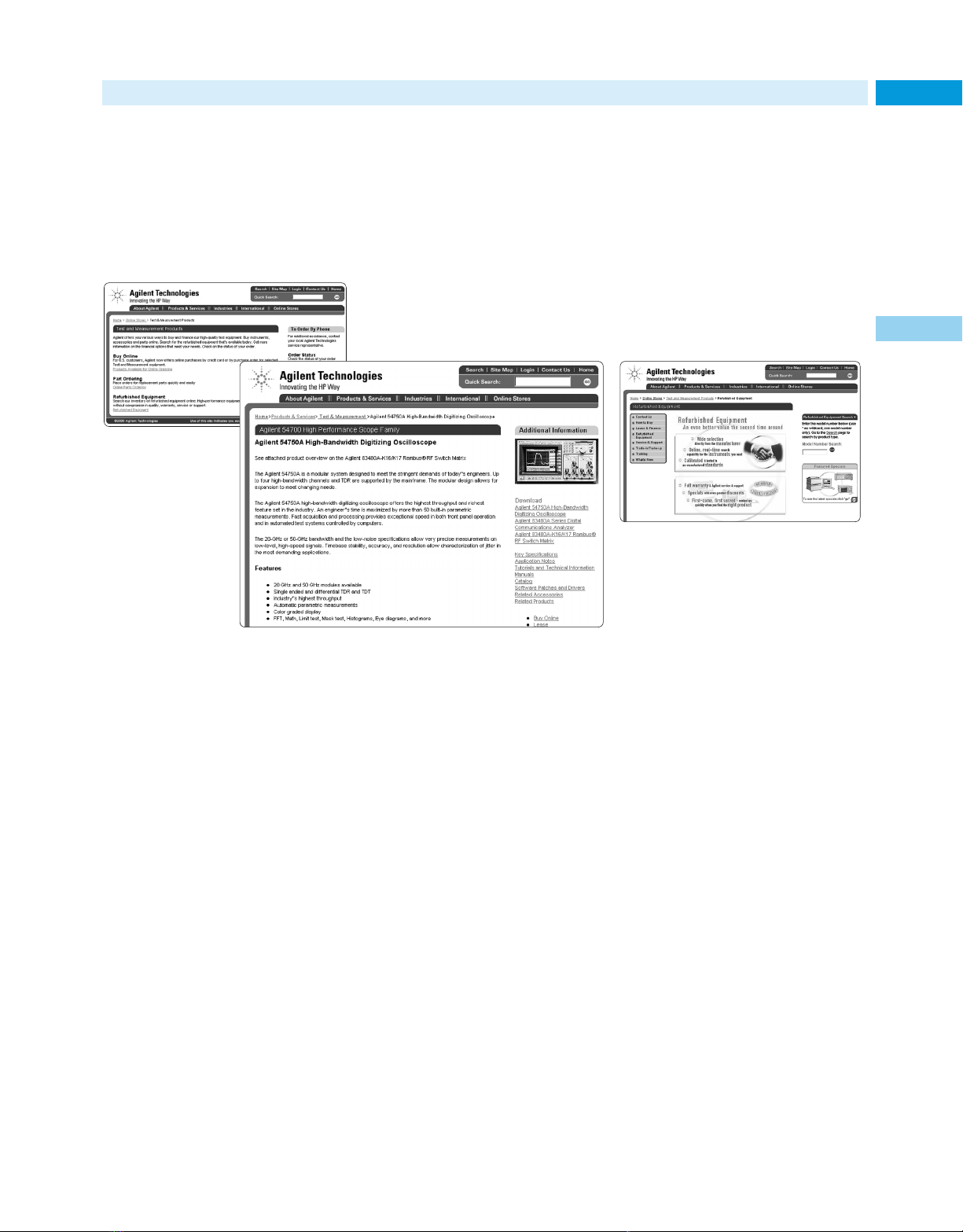
Agilent’s Site on the Internet
Online Business and Information Services
Take immediate action:
Find, get & buy at the Agilent
Technologies web site
35
1
Find
•
Product and support information
more easily with helpful navigation
aids and improved web pages that
make it easier to access application
notes, product overviews, technical
details, frequently asked questions,
manuals, software, news releases,
education coursedescriptions and
schedules, and much more.
*Availability of this feature may be limited; an expansion program
is ongoing. Online purchases require a credit card.
For best results, view the Agilent web site with Microsoft’s
Internet Explorer browser.
Get
• Updated comparison data and
evaluation guides/tools that
facilitate product selections
•
Helpful application notes, downloadable interactive application
notes, tutorials, online models,
and other learning and problemsolving material
•
Quick access to customer support
services
•
Information on recommended replacements for discontinued products
•
Information in your local language*
• The latest information on the status
of your Agilent test and measurement order
Buy
•
Selected Agilent products—including
scopes, logic analyzers, EDA
software, multimeters, data
acquisition products, signal sources,
counters, power supplies, and more*
•
Refurbished instruments*
• Accessories*
• Replacement parts*
For more information on the
test and measurement features,
resources, and services available
on Agilent’s web site, see page 3.
Use our online test and measurement
resources and services often!
www.agilent.com/find/tmc
Page 36
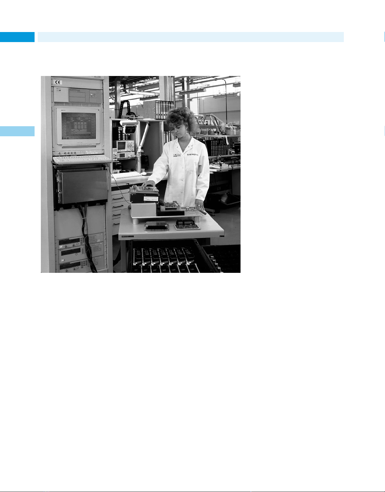
Complete Test Solutions
36
Case studies show customer successes
with Agilent
1
Siemans automotive systems achieves more throughput flexibility at reduced cost
with TS 5400 systems.
In the following pages we have
compiled a set of examples of the
successful “Complete Test Solutions”
developed by Agilent Technologies
and a customer. These represent
large and small companies from
around the world, which have a variety of needs. The thing they have in
common is that in cooperation with
Agilent, they were able to solve a
major test and measurement problem. A brief overview of these case
studies may give you some ideas about
how Agilent can help you improve
your business results.
SS/Loral teams with Agilent to develop
payload test systems to meet present and
future needs quickly and cost effectively
SS/Loral, communications satellite
company, chooses Agilent Technologies
to design, and build automated payload test system. Teamwork, allows
SS/Loral to concentrate on the satellite, while using the specialized skills
of Agilent to create a robust, userfriendly system that meets SS/Loral’s
needs and ensured high-performance
satellite delivery, with capabilities
for extension to future projects.
(Page 37)
Agilent and JOT Test Systems give Bose a
tidal wave of manufacturing productivity
To meet deadlines and stay competitive, Bose Corporation decreases cycle
times and reduces manufacturing
costs, while maintaining highest quality with an Agilent Technologies and
JOT Automation integrated solution.
(Page 37)
Agilent’s acceSS7 helps Illuminet improve
customer service while enhancing network reliability and efficiency
Illuminet operates the largest unaffiliated Signaling System 7 (SS7) network
in the United States, and is growing
rapidly. To maintain its high level of
customer service, while expanding the
network and becoming even more efficient, Illuminet chose Agilent
Technologies acceSS7. (Page 38)
Agilent helps Tellabs cut costs, increase
production volumes, and improve
product quality
Tellabs chose to upgrade its existing
Agilent Technologies test systems to
meet manufacturing goals, in part
due to results the equipment had
already delivered. As a result, Tellabs
has doubled manufacturing test
throughput and cut defects in half,
while reducing overall test costs.
(Page 38)
Motorola AIEG (Europe) speeds production line test development and execution
with Agilent TestExec SL
Motorola AIEG (Europe) uses a new
Agilent Technologies Test Executive
for the automation and execution of
functional tests on an automotive unit
under test (UUT) and reports the
results, achieves improvements in
operating and test execution speed
as well as speed of development
using that platform, thus realizing
the ultimate goal of increased
throughput. (Page 39)
Page 37
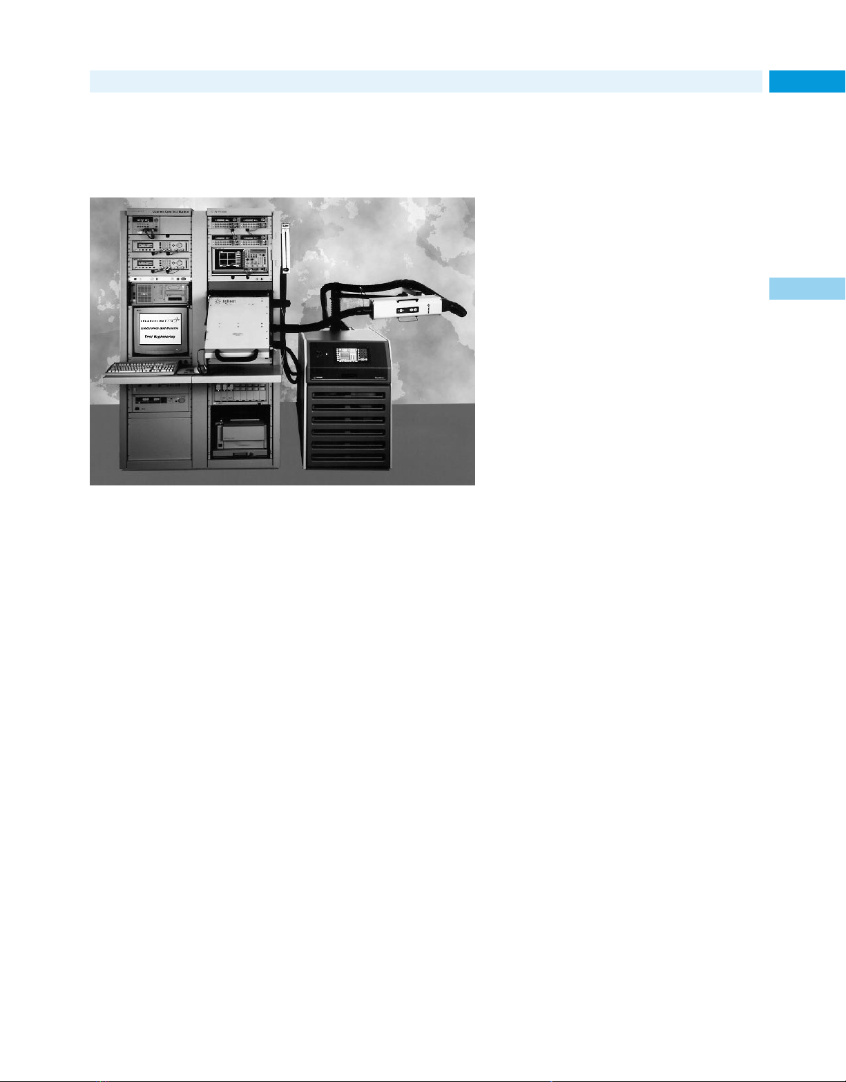
Complete Test Solutions
37
SS/Loral teams with Agilent to develop
payload test systems to meet present and
future needs quickly and cost effectively
Agilent 85121A Payload Test System (PTS) developed for SS/Loral.
Space Systems/Loral (SS/Loral),
a $1.4 billion operation with some
200 satellites to its credit, is one of
the prime players in the design and
manufacture of communication satellites. A subsidiary of Loral Space and
Communications, SS/Loral designs;
builds; and tests satellites, subsystems,
and payloads at its Mission Control
Center in Palo Alto, California.
Regardless of their mission, satellites
don’t fly until they have undergone
complete and comprehensive prelaunch testing. At the same time,
satellite manufacturers are continually
challenged by aggressive production
schedules and rigorous performance
requirements. Understanding the special skills and capabilities needed to
design and build technically appropriate and cost effective payload test
systems (PTS) in-house, while producing state-of-the-art satellite systems,
SS/Loral decided to seek the assistance of test and measurement
experts, who would free them to
focus on what they do best—producing
state-of-the-art satellite systems.
As a result, SS/Loral contracted with
Agilent Technologies to build a new
payload test system. The result was
an automated, robust, user-friendly,
algorithm-based payload test system
for evaluating the RF performance of
communications satellite transponders, telemetry transmitters, and command receivers. Agilent’s system has
simplified and reduced standard processing time, and ensured high-performance satellite delivery. The test system’s modular design also permits
easy upgrade and reconfiguration.
The teaming of SS/Loral and Agilent
has resulted in significant improvements in the way SS/Loral tests its
spacecraft. As SS/Loral moves forward with new developments in the
art and science of spacecraft design,
it will continue to call upon Agilent’s
ingenuity in payload test systems.
“Among the reasons that we selected
Agilent was the fact that our challenges posed no obstacles to them.
They have been in the RF business
for many years, they’ve worked closely with us, and they understand our
business, so overcoming these challenges was, for them, very easy. Any
other company that hadn’t had the
exposure to this business would have
found it much more difficult,” stated
Duncan Blanks, Deputy Director
of Spacecraft Engineering Test
Operation, Space Systems/Loral.
Agilent and JOT
Test Systems give
Bose a tidal wave
of manufacturing
productivity
Bose was founded in 1964 by Dr.
Amar G. Bose, professor of electrical
engineering at the Massachusetts
Institute of Technology (MIT). Dr.
Bose’s findings resulted in significant
new design concepts that help deliver
the emotional impact of live music.
That technology is found in the company’s award winning “Wave” Radio
music systems. Today, Bose technology is present in the Sistine Chapel, the
NASA space shuttles, and the National
Theater of Japan, as well as in homes
and automobiles around the world.
To meet deadlines and stay competitive, Bose Corporation must decrease
cycle times and reduce manufacturing costs while maintaining the highest quality. To do this, Bose uses an
integrated solution from Agilent
Technologies and JOT Automation to
test its consumer audio products.
“Recently, management challenged us
to reduce test time for the Bose Wave
Radio with CD by 25 to 40 percent,”
said Brian Morris, a Bose test engineer. “We turned to a combined solution from Agilent and JOT to get the
job done.”
Bose relies on Agilent 3273 Series 3
Board Test Systems and Agilent 79000
Custom Functional Test Systems
for electronic manufacturing test
of high-volume consumer electronic
products. “Using this Agilent equipment, in conjunction with automated
board handlers from JOT Automation,
we exceeded management’s test time
reduction goals for the Bose Wave
Radio with CD,” said Morris. He
concluded, “Helpful, knowledgeable
Agilent staff provide outstanding
support that reduces costly down
time and further helps us meet our
test and manufacturing goals.”
1
Page 38
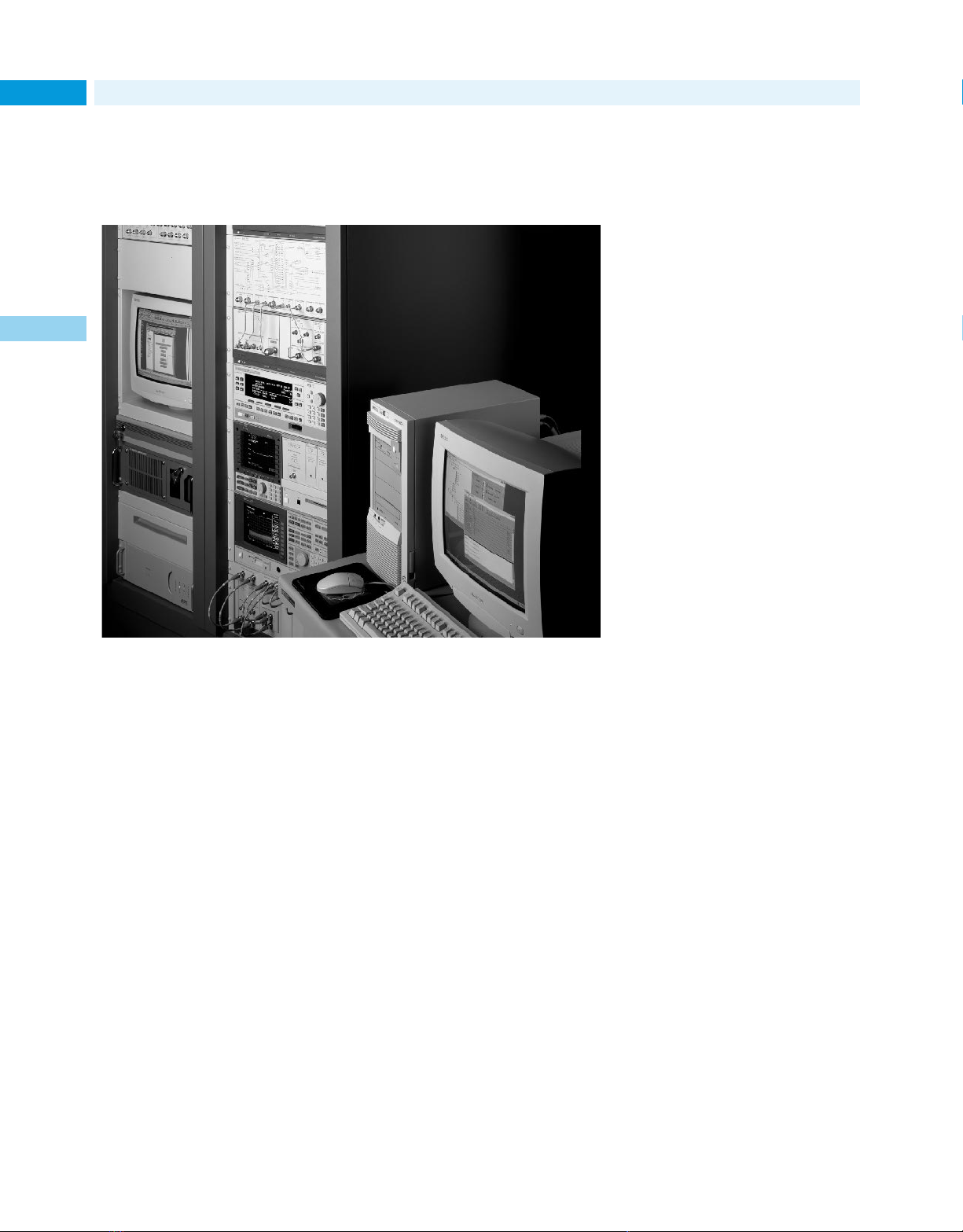
Complete Test Solutions
38
acceSS7 helps Illuminet improve
customer service while enhancing
network reliability and efficiency
1
Agilent helps
Tellabs cut costs
and improve quality
For nearly 25 years, Tellabs has
worked in concert with telecommunications service providers to provide
solutions for managing and optimizing
networks. In the process, the company
has developed a reputation as one of
the foremost suppliers of specialized
communications solutions. As an
infrastructure builder, Tellabs is an
important partner with local and long
distance telephone companies, competitive service providers, cable operators, cellular and other wireless
carriers, and government agencies.
Because of the exploding market
for telecommunications products
increased, their production volume
has grown dramatically. To stay competitive, it is vital for Tellabs to continute improving throughput on manufacturing lines while reducing costs
and maintaining high quality
Agilent acceSS7 system used by Illuminet for network management.
Founded in 1981, Illuminet operates
the largest unaffiliated Signaling
System 7 (SS7) network in the
United States and is a leading
provider of complementary advanced
signaling technology and applications to telecommunications carriers.
Illuminet specializes in signaling network services and intelligent network solutions for a variety of services such as calling name delivery,
calling card validation, wireless
roaming and fraud management, network usage measurement, number
portability, and other specialized
database access functions.
In the past few years, requirements
on Illuminet’s network have increased
dramatically, due to competition and
other changes engendered by the
Telecommunications Act of 1996 and
the explosion in demand for switchbased telecommunications services.
“With growth of 30–40 percent a year
and a network that a lot of telephone
companies depend on, outages are
totally unacceptable to us. We need
to be on top of everything in our network and be able to prevent problems
before they occur,” Ken Helgeson,
Director Network Operations, recalled.
“We need an operational support
system to keep growing the business
and to provide the level of quality and
service that our customers expect,”
stated Bruce Johnson, VP Operations
and Engineering
Illuminet selected the acceSS7 solution
from Agilent as the right operational
support product for managing its network. In addition to meeting its stated
requirements, Illuminet felt that the
Agilent solution could help it attract
additional customers because the
product was so well known and wellrespected in the telephony industry.
“The industry sees us as a company
with a very reliable, robust network
and as being very customer-focused.
The acceSS7 solution has made a significant contribution to our reputation,”
said Bruce Johnson, VP Operations
and Engineering.
Working with Agilent, the Tellabs Long
Island Facility team, under Director of
Manufacturing Ed Pruitt, decided it
could improve productivity, while
maintaining high quality, by using
recently upgraded test systems from
Agilent Technologies. As a result,
Tellabs has doubled manufacturing
test throughput and cut defect rates in
half while reducing overall test costs.
Agilent provided Tellabs with a “Total
Solution” consisting of a Series 2 upgrade to its Agilent 5DX X-ray Test
System, STC Series 2 upgrades on
both of its Agilent 3079 Functional
Communications Test Machines,
while Tellabs also added a second
Agilent 79000 Functional Test
System. The upgraded 3079 systems
tests boards in seconds without
requiring specialized test equipment,
highly skilled technicians, complex
programming, or simulation.
“Additionally, extra cost savings are
realized through reduced floor space
requirements, reduced operator
labor, improved system support, and
improved quality via statistical
process control,” concluded Pruitt.
Page 39
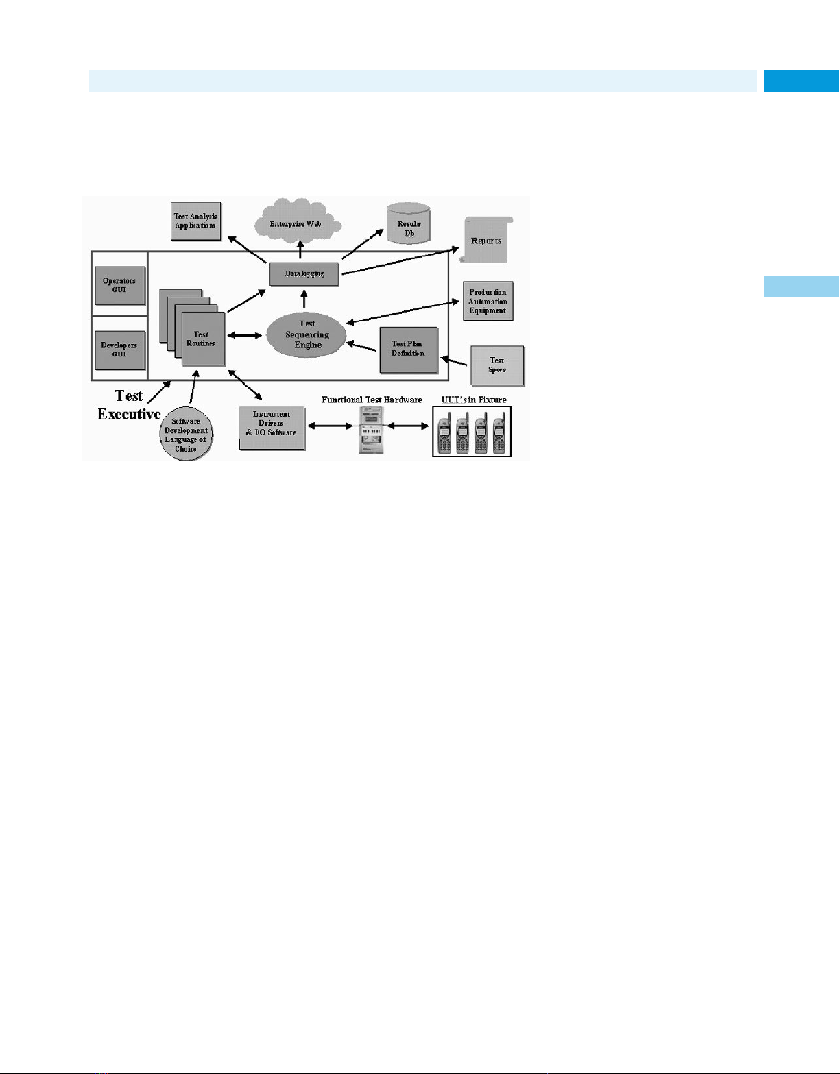
Speeding production line test
Complete Test Solutions
39
development and execution at
Motorola AIEG (Europe)
Figure 1–Typical functions of a test executive. Users must be able to configure each
module for application-specific needs.
Motorola Aotomotive and Industrial
Electronics Group’s (AIEG) challenge:
increased throughput
Motorola AIEG (Europe)’s automotive
electronics manufacturing, with facilities in Stotfold, UK and Angers, France,
designs and produces electronic modules for a variety of automotive functions. These include engine management, chassis/body control, climate
control, and—the newest bright star in
the automotive universe—telematics,
which enables the vehicle to report its
position and mechanical condition in
realtime to a central dispatch system
for road service.
The Agilent workstation-based platforms Motorola had been using, running on its own software, were
becoming obsolete and Motorola
AIEG Strategic Test Development
was looking for improvements in
operating and test execution speed
as well as speed of development
using that platform, the ultimate
goal being increased throughput.
With the announcement of the availability of the significantly improved
Series 2, including the Agilent Tech-
nologies TestExec SL, Motorola decided
to put it to the test. “We had it in mind
for a project that was coming up,” says
Motorola’s Test Engineering Specialist
Phil Heredge, “so we went ahead and
ordered it. I believe we received the
first one off the production line.”
Motorola was looking for low cost,
high throughput, reliability, and an
easy-to-use development environment. The last point was critical and
the system answered the need nicely.
Bundled with the system was the
TestExec SL software environment.
“There were a lot of features we
liked,” says Heredge. “Running on
Windows NT, we found it was pretty
stable. It provided a good development environment—intuitive and
easy to learn. We were able to generate solutions for the factory floor in
a significantly reduced number of
weeks. And there’s a lot of reuse of
modules and code with TestExec SL.”
Agililent Technologies Solution
TestExec SL simplifies considerably
the development of test executives. A
test executive is a management system for automating the execution of
functional tests on a unit under test
(UUT) and reporting the results
(Figure 1). Its capabilities include
test sequencing, limit checking, data
logging and export, operator run-time
interface, and other functions. An
effective test executive program features a modular component architecture, quick and easy system configuration, common instrument support,
and extensive measurement routine
libraries. Users expect powerful configuration tools that allow them to
make simple measurements without
writing extensive software routines.
“Phil and his manager, Adrian Carter,
took a walk-before-we-run approach
to the acquisition of test systems,”
says Steve Stetler, Agilent Application
Engineer. “We were initially successful in introducing one system into
Motorola Stotfold that tested the Air
Condition Control Module. We worked
with Workstation Source, a thirdparty contractor who handled the
quite elaborate mechanical fixturing.”
Within Europe, Motorola now has a
total of ten systems in place, testing
engine management, climate control,
and telematics products.
Results and Benefits: higher productivity
Agilent is now working with Motorola
on the new telematics modules. The
module combines the functions of
GPS, GSM, and fault monitoring. And
TestExec SL is the platform on which
all the tests will be built.
Phil Heredge sums up Motorola’s
experience with TextExec SL this
way: “Our test engineers quickly
learned this intuitive development
environment. Migrating to this platform allowed them to concentrate on
value added tasks rather than source
code generation. TestExec SL’s many
good features include a hierarchical
switching path editor, live instrument
panels, and the ability to add or
remove debug features without compilation. With debug speeded up, we
have significantly reduced the time
required for developing a functional
test solution for manufacturing.”
1
Page 40

New Products Overview
Table of Contents & Overview
40
Wireless 41
RF & Microwave 46
Communication Test 50
Lightwave/Component Test 54
Manufacturing Test 55
Semiconductor Test 58
Design Automation 59
General Purpose 59
Digital Design & Debug 62
Innovative products that make a difference
The exciting new Agilent Technologies
1
products highlighted in this catalog
section offer you important new
capabilities and new and enhanced
benefits. They reflect the wide scope
of our research and development
investments, as well as our corporate
acquisitions. They also underscore
Agilent’s unwavering commitment to
meeting your changing test and measurement needs with continually
improved instruments, systems,
software, and services.
Among the many characteristics that
Agilent products exhibit, and the trends
they help drive, are the following:
More value and affordability—Greater
value, with nothing left out, has been
achieved through improved designs,
patented measurement techniques,
higher integration, and more efficient manufacturing processes.
Greater ease of use—Features such as
one-button test capabilities, voice
control, and sophisticated graphical
user interfaces make Agilent instruments easier to operate and help you
achieve results more quickly.
Higher performance—Extended performance limits permit insights into
problems that were previously
impossible to analyze.
Faster test speeds—Higher measurement throughputs increase productivity in both engineering and production environments, while helping
to reduce test costs.
More powerful methodologies—Faster,
more insightful analysis and troubleshooting techniques let you diagnose
problems better and with unprecedented speed.
Technical breakthroughs—Unique solutions to long-standing problems,
developed by Agilent researchers and
engineers, continue our legacy of
product innovations.
Expanded flexibility—New hardware
and software products add more
capabilities, including state-of-the-art
functionality, boosting the utility of
versatile platforms.
Enhanced familiarity—Commonly used
elements of computer operation have
been leveraged to provide familiar
environments that allow you to spend
more time on your project and less
time learning to use an instrument.
Improved data-analysis capabilities—
Agilent instruments make it easier
than ever to complete the entire test
and measurement task, including
data analysis and report preparation.
Modular designs—Modular test solutions give you great measurement
flexibility with considerable economy—a combination that offers value
now and in the future.
LAN connections—More Agilent instruments have LAN connections for
intranet and Internet connectivity,
facilitating remote operation, data
sharing, and access to Agilent services and many other resources.
Upgradeability—The flexible architectures of many Agilent instruments
enable timely software performance/
feature upgrades that extend the
equipment’s useful life and safeguard
your capital investments.
Inter-system collaboration—Linkage
software allows test systems such as
an x-ray inspection machine and an
in-circuit tester to collaborate intelligently to decrease test redundancy,
reduce fixture complexity, and boost
fault coverage.
Portability—Many Agilent test and
analysis instruments are exceptionally small and lightweight, so they can
be easily carried to problem sites for
efficient troubleshooting.
Computer-standard technologies—
Agilent strongly advocates the industry’s drive to develop test and measurement solutions that use computer-standard technologies for I/O,
instrument access and control, and
instrument-based solution development and maintenance.
Application-specific solutions—Agilent
supports the complete test engineering solution process, from consulting
services to fully configured test systems, and offers standard products
optimized for key applications such
as data communications.
More products, more solutions—Agilent
Technologies, the worldwide test
and measurement leader, offers you
the industry’s most extensive, most
trusted line of standard and custom
solutions. The new products for
2001 build on a vast base of existing
products. To obtain a more complete
picture of how the thousands of
Agilent products and services can
help you, please refer to the subject
index, which begins on page 6.
If you need additional information
on a specific application, contact the
Agilent Call Center in your region.
Page 41
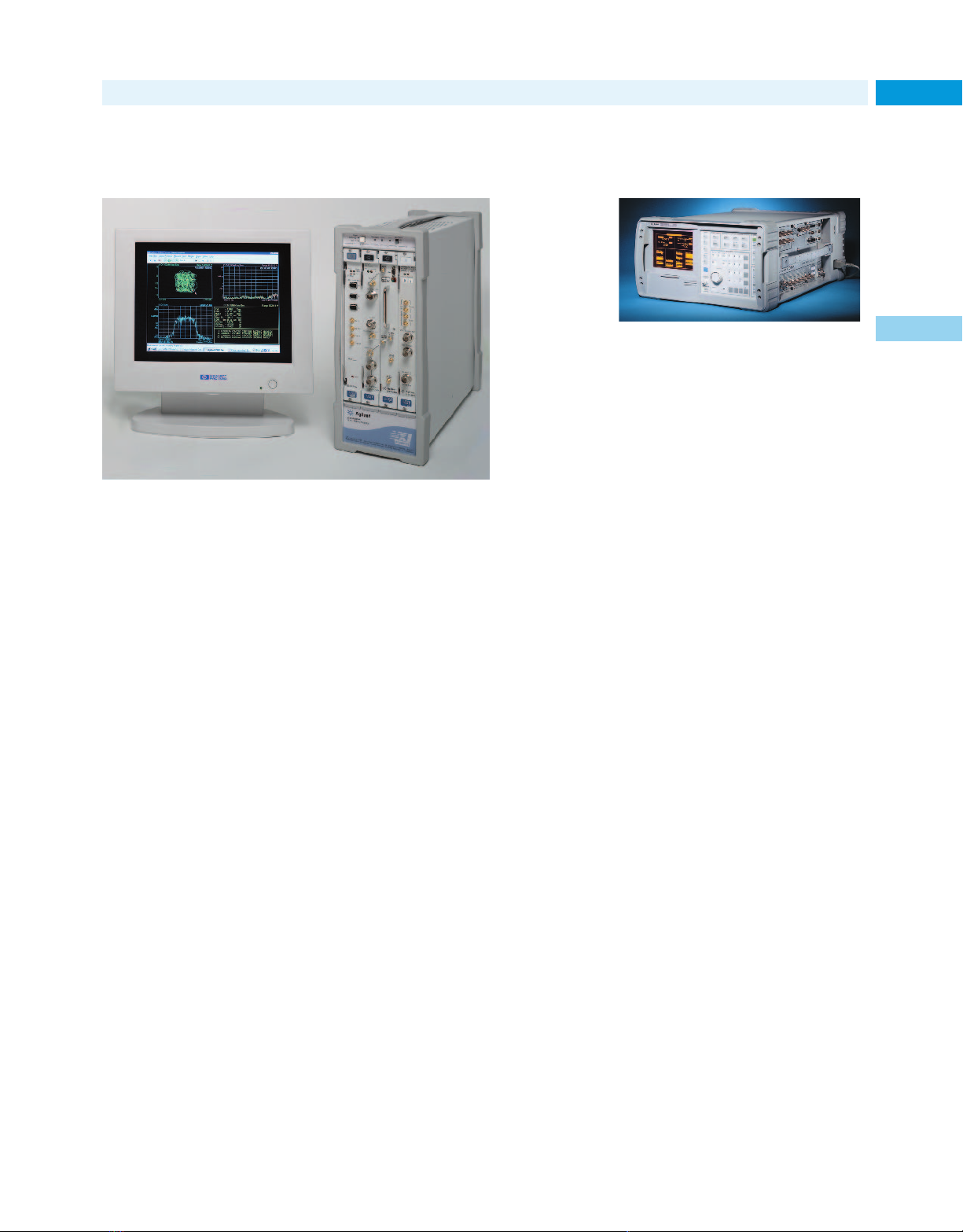
New Products for 2001
Use time-, frequency-, and modulation-domain
analysis to speed communication system design
These vector signal analyzers, linked to EDA software, ease communication
system design from first simulation to final hardware prototype.
Agilent Technologies’ 89600 series
vector signal analyzers (VSAs)—the
89610A (dc to 40 MHz) and 89640A
(dc to 2.7 GHz)—have frequencydomain, time-domain, and modulationdomain analysis functions. They give
you the measurement tools you need
for digital communications applications, especially those that have
wideband formats.
Use the VSAs to make measurements
on baseband, IF, or RF signals. The
analyzers handle a wide span of
modulation formats and variable
symbol rates, and provide a variety
of filters. View measurement results
in constellation, eye, trellis, spectrum, or time displays.
Link analyzer with EDA software
The VSAs can be linked tightly to
Agilent’s Advanced Design System
(ADS) electronic design automation
(EDA) software. Now you can use the
same tools throughout the design and
development phases of your product.
Evaluate both the computed results
from the simulation software and the
measured data from your prototypes
using the same processing algorithms.
symbol clock, filtering, and other
DSP problems. Identify unwanted
signals in modulated carriers using
the EVM spectrum function.
The VSAs have an adaptive equalization function that removes linear
errors from I/Q modulated signals
by dynamically creating and applying
a compensation filter. They also let
you analyze signals for instantaneous
amplitude, frequency, or phase versus
time. Characterize phase noise,
oscillator frequency transitions,
and transmitter turn-on behavior.
Perform statistical measurements of
peak, average, and peak-to-average
power, including the complementary
cumulative distribution function
(CCDF), too.
The 89600 series analyzers have
extremely flexible triggering. Their
PC-based measurement software
makes it easy to automate measurements. User-defined macros simplify
recording key strokes or mouse
clicks so test procedures can be
saved and reused.
For more information, see page 260.
Wireless
Maintain and expand your
cdma2000 1XR-TT network
Get the measurement capabilities
you need to upgrade your wireless
network services.
For most IS-95 operators, cdma2000
SR-1 technology will allow increased
spectral efficiency and higher data
transfer rates for such applications
as the Internet. The Option 200 for
the Agilent E6380A tester facilitates
wireless network service upgrades.
With this option, the tester is ideal
for measuring the performance of
cdma2000 SR-1 (1XRTT) systems.
It provides
• a power display for 128 code
channels and supplemental
channels in bit-reverse order
• a noise power display for each code
• total power and code channel
width capability (number of
supplemental channels)
• a complex power function that
displays power in 128 I and
Q code channels prior to shortcode spreading
• an I-Q constellation diagram that
indicates decision points for one
or more symbols
• a function that computes the estimated Rho for cdma2000 signals.
For more information, see page 359.
For detailed specifications, circle 2 on
the reply card (last page) or contact the
Agilent Call Center in your region (see
page 604).
41
1
Signal quality measurements
The VSA’s EVM (error vector magnitude) versus time measurements
let you analyze carrier frequency,
For detailed specifications, circle 1 on
the reply card (last page) or contact the
Agilent Call Center in your region (see
page 604).
Page 42
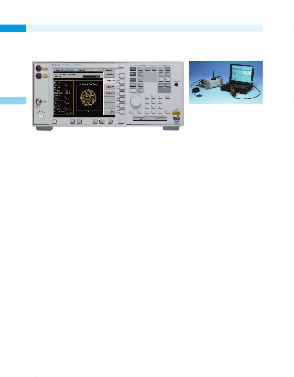
New Products for 2001
Wireless
42
Reduce test time with the E4406A’s EDGE, W-CDMA,
and cdma2000 measurement personalities
1
The new and enhanced 2.5/3G measurement personalities for the E4406A VSA offer
fast, accurate one-button standards-compliant measurements.
New EDGE measurement capability
The Option 202 measurement personality adds EDGE measurement
capability to the Agilent E4406A vector signal analyzer (VSA). This
option enables you to perform fast,
one-button, standards-compliant
measurements that can help you
move your product smoothly from
design verification to manufacturing.
Quickly and simply make complex
measurements, such as:
• error vector magnitude (EVM)
• output RF spectrum (ORFS)
• power versus time (PvT)
A unique measurement algorithm and
industry standard filter are used in
Option 202. This allows the VSA to
display a highly accurate EDGE constellation diagram while simultaneously reporting numerical EVM results.
The EDGE measurement personality
also includes GSM test capability.
W-CDMA and cdma2000 enhancements
The W-CDMA measurement personality (Option BAF) and the cdma2000
measurement personality (Option
B78) for the E4406A will keep you
current with the latest changes to
3G standards specifications. These
personalities enable you to make
standards-compliant measurements,
using preprogrammed routines, at
the touch of a button. The enhancements include:
• code domain analysis measurements to verify the channel structure of the hybrid phase shift key
(HPSK) modulation scheme of
mobile handsets
• a composite EVM measurement
to perform modulation quality
analysis, including code domain
error, for multiple data channels
• an adjacent channel power measurement that now includes a root
raised cosine filter to comply with
the latest standard for 3GPP.
New measurements added to Options
BAF and B78 include a spectrum
emission with mask for spurious
search capability (up to 4 GHz),
occupied bandwidth and intermodulation distortion.
For more information, see page 379.
For detailed specifications, circle 3 on
the reply card (last page) or contact the
Agilent Call Center in your region (see
page 604).
CDMA over-air
maintenance tool
Perform proactive CDMA base station
maintenance without leaving the vehicle.
The Agilent E7490A CDMA over-air
maintenance tool is used to make
diagnostic measurements of IS-95
and J-STD-008 CDMA base stations
over the air. The system lets you perform proactive maintenance of even
hard-to-reach base stations efficiently and economically. With an increasing number of base-station pole-top
deployments, this tester gives cellsite technicians fast and easy firstlevel diagnostics without getting out
of their vehicle.
The E7490A software runs on a PC
that interfaces with an Agilent digital receiver and/or a CDMA mobile
phone. The receiver-based measurements include code domain power,
pilot signal measurements, and
dynamic traffic channel measurements. The phone-based testing exercises individual base station channel
elements. The over-air measurement
system also has data recording and
playback capability.
The Agilent E7490A maintenance
tool is completely scaleable with
Agilent drive test system products.
The optional capabilities can be
integrated at any time.
For more information, see page 361.
For detailed specifications, circle 4 on
the reply card (last page) or contact the
Agilent Call Center in your region (see
page 604).
Page 43

New Products for 2001
Wireless
Drive-test systems facilitate evaluating and troubleshooting wireless networks,
outdoors and indoors
The vehicle-mounted display system
makes Agilent’s wireless network optimization tools easier to use.
holds the receiver(s), phones, batteries,
Examine impairments to 3G and GPRS networks during a drive through of
a coverage area, and even while walking through a building.
integrated antennae, and all the associated cabling.
43
1
Agilent’s portable solutions for
wireless network air interface testing
are ideal for outdoor—and indoor—
optimization, transceiver site selection
and evaluation, network performance
characterization, and troubleshooting.
They can help you speed up network
turn-on, optimize network performance, maximize productivity, and
minimize drive test cost.
Optimize 3G networks
Based on the scaleable E7470-series
platform, the new E7476A and
E7477A drive test systems are optimization solutions for 3G networks.
The E7476A (for W-CDMA networks)
and E7477A (for cdma2000 networks)
help you eliminate network problems
quickly, while also improving network quality, decreasing downtime,
and reducing costs. These drive test
systems can be fully integrated into
other E7470-series products, so you
can perform drive testing across
multiple network technologies and
frequency bands simultaneously.
Drive-test GPRS networks
As service providers and equipment
manufacturers roll out General
Packet Radio Service (GPRS), they
can use the Agilent E7478A drive test
system to quickly optimize and trou-
bleshoot their networks. The system
provides mobile measurement
reports and protocol decode information to allow air interface characterization and fast problem resolution.
Measure GPRS data uplinks/downlinks
The convergence of cellular telephones
and the Internet mandates that wireless networks be optimized for data
transfer. New options for Agilent
E7478A drive test products allow
end-to-end testing of data connections
with independent uplink and downlink
measurement results. Key data characteristics, data throughput, and network accessibility can be measured and
recorded for post processing analysis.
Measure indoor RF coverage
Customers want to use their wireless
phones anywhere—including indoor
locations. Now you can measure the
quality of indoor RF coverage using the
same tools used for outdoor drive testing. The Option 180 extends the capabilities of an Agilent drive test system
to characterize 3G, GPRS, CDMA, GSM,
TDMA, and AMPS networks indoors.
The indoor measurement system has a
pen-tablet computer for quick data
entry onto a computerized floor plan,
and a suspension system to support
the computer. A customized backpack
Vehicle-mounted display
The Agilent N3419A vehicle-mounted
display system improves safety, boosts
efficiency, and allows real-time troubleshooting while using Agilent’s
E7470-series drive test systems and
the E7490A over-air maintenance tool.
It consists of a bright display, adjustable pedestal mounting, and a custom
keypad with application-specific keys.
During a drive through a network coverage area, the N3419A system makes
it easy to examine network impairments as they occur. Information such
as location, time of day, vehicle traffic
conditions, and terrain can be noted
to aid problem solving. Essential measurement functions such as starting
and stopping calls, recording data,
and turning alarms on and off are
performed by pressing just one key.
(Safe driving must always be maintained when using this equipment.
Availability of the Agilent N3419A
is subject to local regulations.)
For more information, see page 392.
For detailed specifications, circle 5 on
the reply card (last page) or contact the
Agilent Call Center in your region (see
page 604).
Page 44
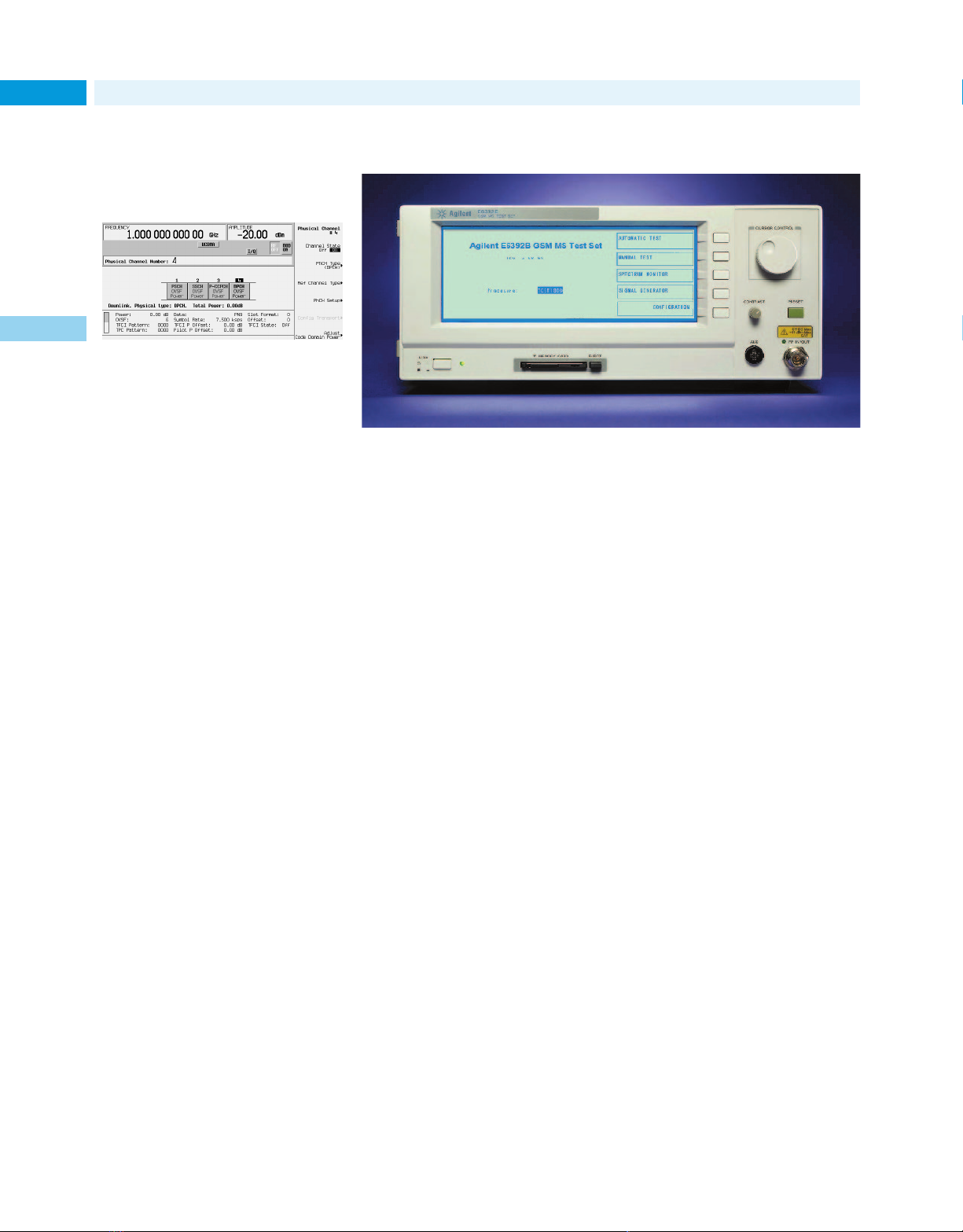
New Products for 2001
Wireless
44
designs with a fully
coded signal
1
The flexible Option 200 personality lets
you change many channel parameters.
Option 200 personality enables the
Agilent ESG-D/DP family of signal
generators to produce a fully coded
real-time W-CDMA signal. This new
capability enables developers to verify mobile receiver and base station
designs for accuracy and standards
compliance. The Option 200 complements the Option 100 personality,
which provides a partially coded
multi-carrier W-CDMA, useful for
component testing.
With the latest revision to the 3GPP
standards, the Option 200 personality
supports reference measurement
channels for BLER/BER. It generates
physical data, control, and synch
channels, while allowing adjustments
of the channel parameters. Data bits
can be inserted at the transport layer
or physical layer, so the ESG-D/DP/
Option 200 combination can be used
for different stages of testing.
For more information, see page 205.
For detailed specifications, circle 6 on
the reply card (last page) or contact the
Agilent Call Center in your region (see
page 604).
Expanded capability for GSM mobile-phone repairsVerify your W-CDMA
Service shops can use mobile station test set to economically increase their cellular
telephone repair and calibration capability.
The Agilent E6392B GSM mobilestation test set has more capabilities
for module-level repair and calibration. The frequency range has been
extended to cover the U.S. PCS1900
frequency band. A dual-band handover test capability allows service
technicians to easily verify whether a
GSM900/DCS1800 dual-band phone
can properly hand off calls between
the GSM and DCS networks. There are
now six channels in the test set for
fixed traffic-channel measurements,
providing greater flexibility for testing hand-overs in multiple bands.
To aid the adjustment and calibration of phones after repair, the test
set now includes an 11-V dc source,
an async test mode for measuring
transmitter power, and optional
0.5-dB signal generator steps for
receiver testing.
Cut GSM phone repair costs
The E6392B test set provides module-level repair capability for the
price of an entry-level, go/no-go
tester. By extending troubleshooting,
repair, and calibration activities to
local shops, GSM service providers,
and mobile-phone-repair organizations can keep equipment costs in
line and reduce the number of "no
trouble found" phones that get sent
back to the manufacturer.
For more information, see page 373.
For detailed specifications, circle 7 on
the reply card (last page) or contact the
Agilent Call Center in your region (see
page 604).
Page 45

New Products for 2001
Complete test solution
for cdma2000 designs
This is the cdma2000 link control display of an ESG-D/DP signal generator
with the Option 201 personality.
With the Option 201 personality,
real–time cdma2000, you can use an
Agilent ESG-D/DP signal generator
to simulate a base-station transmitter or a mobile receiver to create SR1
IS-2000 signals.
TDMA and CDMA peak and average power
measurements
Wireless
45
1
Conduct frame or bit-error tests and
functional tests of the mobile unit’s
protocol handling. Option 201 is backward-compatible with IS-95 systems
using Radio Configurations 1 or 2.
The ESG-D/DP/Option 201 combination produces fully-coded channels,
including pilot, sync, paging, quick
paging, and fundamental and supplemental traffic channels, plus OCNS.
Channels are easily configurable
using the built-in table editor. You
can control the power level, FIR filter
type, PN offset, Even-Second delay,
and other parameters, depending on
the type of channel.
For more information, see page 206.
For detailed specifications, circle 8 on
the reply card (last page) or contact the
Agilent Call Center in your region (see
page 604).
Peak and average power meters and sensors allow fast measurements on wireless
communications signals
The Agilent EPM-P series power
meters, the E4416A single-channel
and E4417A dual-channel models, are
used with the E9320 power sensors
to make accurate power measurements. You can perform peak, peakto-average ratio, and average power
measurements on all the common
modulation formats used in wireless
communications. Time-gated power
measurements can also be made
using the meters’ comprehensive
triggering features.
The EPM-P series power meters are
compatible with both the E-series
and 8480-series power sensors. When
used with E9320 sensors, the meters
can perform power measurements at
rates up to 1000 readings per second
over the GPIB. This speed reduces
test times and improves throughput.
The flexibility of the power meters
is enhanced by the range of products
in the E9320 power sensor family.
Two frequency ranges are available:
50 MHz to 6 GHz, and 50 MHz to
18 GHz. There are also three modulation bandwidths:
• 300 kHz for TDMA signals
• 1.5 MHz for CDMA (IS-95A) signals
• 5 MHz for wideband-CDMA signals
Select the modulation bandwidth
required for your application, while
maintaining the widest possible
dynamic range.
For more information, see page 303
For detailed specifications, circle 9 on
the reply card (last page) or contact the
Agilent Call Center in your region (see
page 604).
Page 46
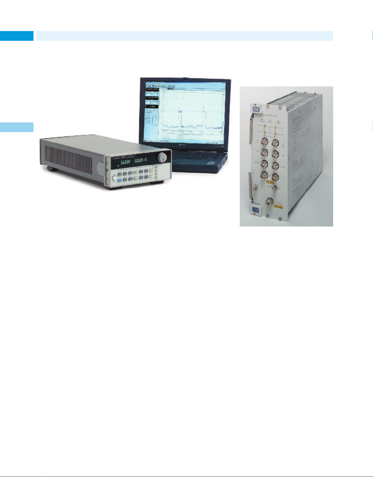
New Products for 2001
RF & Microwave
46
High-performance mobile communications
dc sources with battery emulation
1
Replace the battery and power adapter/charger during design and test of digital
wireless appliances.
High-performance Agilent 66319B/D
dual-output and 66321B/D singleoutput dc power sources meet the
performance testing demands that
wireless appliances place on their
batteries. The dc sources offer very
fast output transient response, very
low voltage drops, and excellent output stability for either short or long
load leads (up to 6 meters). In addition, they provide three current measurement ranges for increased measurement accuracy. This ensures
accurate off-mode, standby-mode, and
talk-mode currents measurements.
Increase throughput up to 30x
The sources’ fast transient output
technology and fast measurement
system allow test throughput increases of up to 30x, compared to general
purpose dc power sources. In addition, the 66319B/D and 66321B/D
allow the elimination of fixture
capacitors and resistors, which
improves test throughput and current
measurement accuracy.
Simulate battery resistance
The dc sources have a built-in output
resistance programming capability
that can be used to simulate the
resistance of the internal battery
pack used in a wireless device.
Various batteries can be simulated,
including Ni-Cad, Ni-mH, Li-Ion, and
Li-Poly types.
Powerful graphics software
The Agilent 14565A device characterization software can be used with the
dc sources to create a powerful wireless appliance test solution that
doesn’t require any programming.
For more information, see page 173.
For detailed specifications, circle 10 on
the reply card (last page) or contact the
Agilent Call Center in your region (see
page 604).
Microwave source
for broadband digital
communications
Use I/Q modulation to perform stimulus
response tests on broadband digital
communication systems.
The Option UNG adds I/Q modulation capabilities to the Agilent
E6432A VXI microwave synthesizer,
making the synthesizer an ideal solution for emerging broadband digital
communications applications, satellite tests and complex radar testing.
Option UNG provides a 40-MHz I/Q
bandwidth over the 10-MHz to
20-GHz range of the E6432A.
For wireless designs that use Bluetooth technology, the fast switching
speed provided by the E6432A synthesizer with the Option UNG allows
the generation of Bluetooth format
signals that can do the full-range
frequency hopping as defined in the
specifications.
For more information, see page 217.
For detailed specifications, circle 11 on
the reply card (last page) or contact the
Agilent Call Center in your region (see
page 604).
Page 47
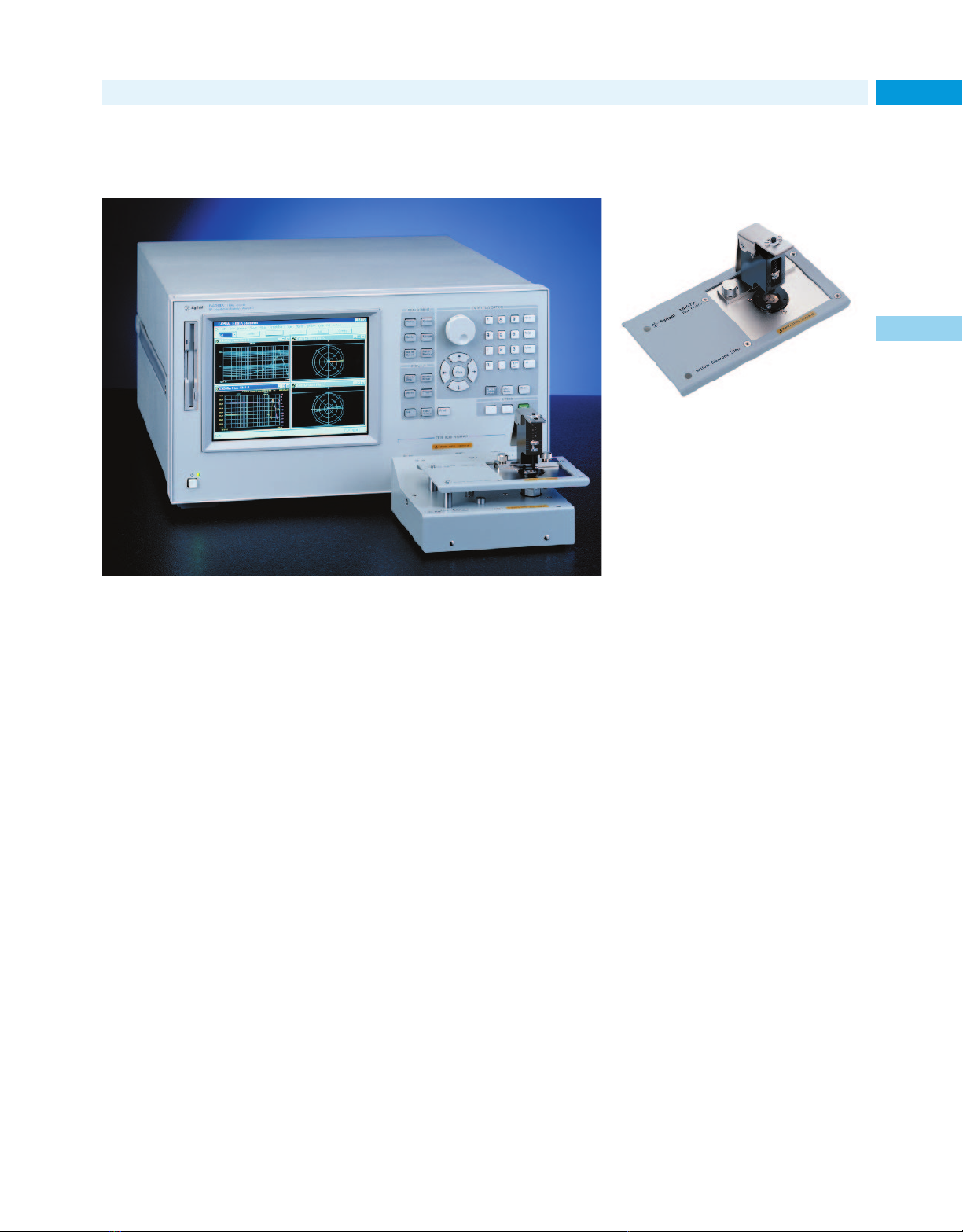
New Products for 2001
Impedance/material analyzer provides accurate
measurements at up to 3 GHz
Analyze components and materials accurately at frequencies up to 3 GHz with the
RF impedance/material analyzer and its test fixtures.
RF & Microwave
SMD test fixture for
impedance measurements
up to 3 GHz
The Agilent 16197A can help you perform
accurate measurements of chip inductors
and other passive RF components.
The Agilent 16197A test fixture
improves impedance evaluations of
bottom electrode surface-mount
devices (SMDs) up to 3 GHz. The
fixture accommodates various sizes
of SMDs; as small as 1005 (mm)/
0402 (inch) and as large as 3225 (mm)/
1210 (inch).
47
1
The Agilent E4991A RF impedance/
material analyzer offers a new level
of impedance measurement performance and offers exceptionally powerful and versatile analysis functions. It can help circuit designers
better evaluate components at frequencies up to 3 GHz. The E4991A
also has dielectric/magnetic material
measurement capabilities over a
wide frequency range: 1 MHz to 1 GHz.
The analyzer’s list-sweep function
improves test throughput, and its
test signal-level ranges enable the
evaluation of devices under actual
operating conditions. An internal
VBA programming function is also
useful for research and development
applications. These and other functions allow drastic improvements to
engineering productivity.
The E4991A’s color display provides
a clear view of measurement settings and results. The analyzer uses
a Windows-type user interface.
Menus that provide easy access to
advanced features. The standard
TCP/IP-compliant LAN interface
implements seamless connectivity
for direct data readouts to a PC.
SMD test fixtures for the E4991A
simplify measurements and help
ensure accurate, repeatable results.
For more information, see page 487.
For detailed specifications, circle 12 on
the reply card (last page) or contact the
Agilent Call Center in your region (see
page 604).
Positioning adjustments are eliminated by the test fixture’s device guide,
which places the SMD precisely over
the measurement terminals. As a
result of the precision positioning of
the SMD, the 16197A boosts measurement repeatability. A pressure
arm comes down vertically and
presses the SMD down onto the measurement terminals, helping to
ensure stable contact. A lever swiftly
moves the pressure arm up and
down for fast operation.
For more information, see page 488.
For detailed specifications, circle 13 on
the reply card (last page) or contact the
Agilent Call Center in your region (see
page 604).
Page 48
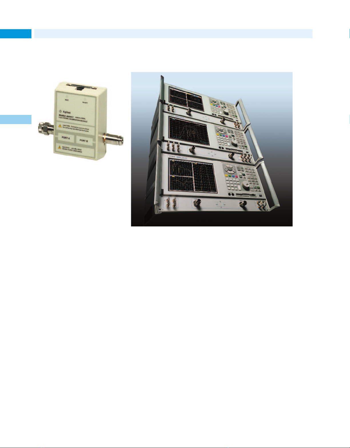
New Products for 2001
RF & Microwave
48
Calibrate vector network
analyzers quickly, easily,
and accurately
1
Perform accurate, repeatable measurements of components with electronic
calibration.
Traditional mechanical calibrations
require intensive operator interaction, which is prone to errors. With
Agilent’s electronic calibration
(ECal) products, the operator simply
connects an ECal module to the network analyzer, then the ECal software controls the rest of the process.
This approach is much easier than
performing a full 2-port calibration of
a network analyzer using a mechanical calibration kit. The ECal solution
produces accurate results, yet takes
less than half the time and requires
50% fewer connections.
The improved ECal modules are easily
controlled directly from the USB port
of an Agilent PNA series analyzer.
They can also be used with all other
Agilent network analyzers, controlled
via a PC running Windows 95 or
NT 4.0.
The ECal modules (male-female,
male-male, and female-female
types) are available with Type-N
(50 Ω and 75 Ω), 3.5-mm, Type-F,
and 7-mm connectors.
For more information, see page 299.
For detailed specifications, circle 14 on
the reply card (last page) or contact the
Agilent Call Center in your region (see
page 604).
Network analyzer has fast sweep speeds and a
wide dynamic range
These network analyzers are designed to meet your measurement needs
now and well into the future.
Is designing and testing leading-edge
RF devices pushing the limit of your
existing test equipment? If so, consider buying an Agilent PNA series
network analyzer: the 3-GHz E8356A,
6-GHz E8357A, or 9-GHz E8358A.
They have the capabilities needed to
meet your measurement needs both
now and well into the future.
The PNA series analyzers feature
exceptional performance, connectivity,
and automation flexibility. They provide fast sweep speeds (35 µs/point),
wide dynamic range, and low trace
noise. Now you will be able to see
aspects of your component’s performance that you never could before.
The analyzers’ connectivity features
help you achieve new levels of integration for your device-measurement
processes. Move information to and
from the instrument using a variety
of built-in interfaces. Save data easily
to the built-in floppy disk, internal
hard drive, or external PC or server
using the familiar Windows GUI. For
hard copies, send measurement
results to any Windows-compatible
printer with a LAN, USB, serial, or
parallel interface. Control other
equipment in the test station directly
from the network analyzer, using any
of the built-in GPIB, LAN, serial, or
parallel interfaces. The LAN interface
also enables remote troubleshooting.
Automate your test processes
using several powerful automation
approaches. You can control the PNA
series network analyzer using SCPI
commands, or gain the speed and
connectivity advantage of COM/
DCOM. Programs can be executed
internally on the network analyzer
or externally on your PC.
For more information, see page 274.
For detailed specifications, circle 15 on
the reply card (last page) or contact the
Agilent Call Center in your region (see
page 604).
Page 49
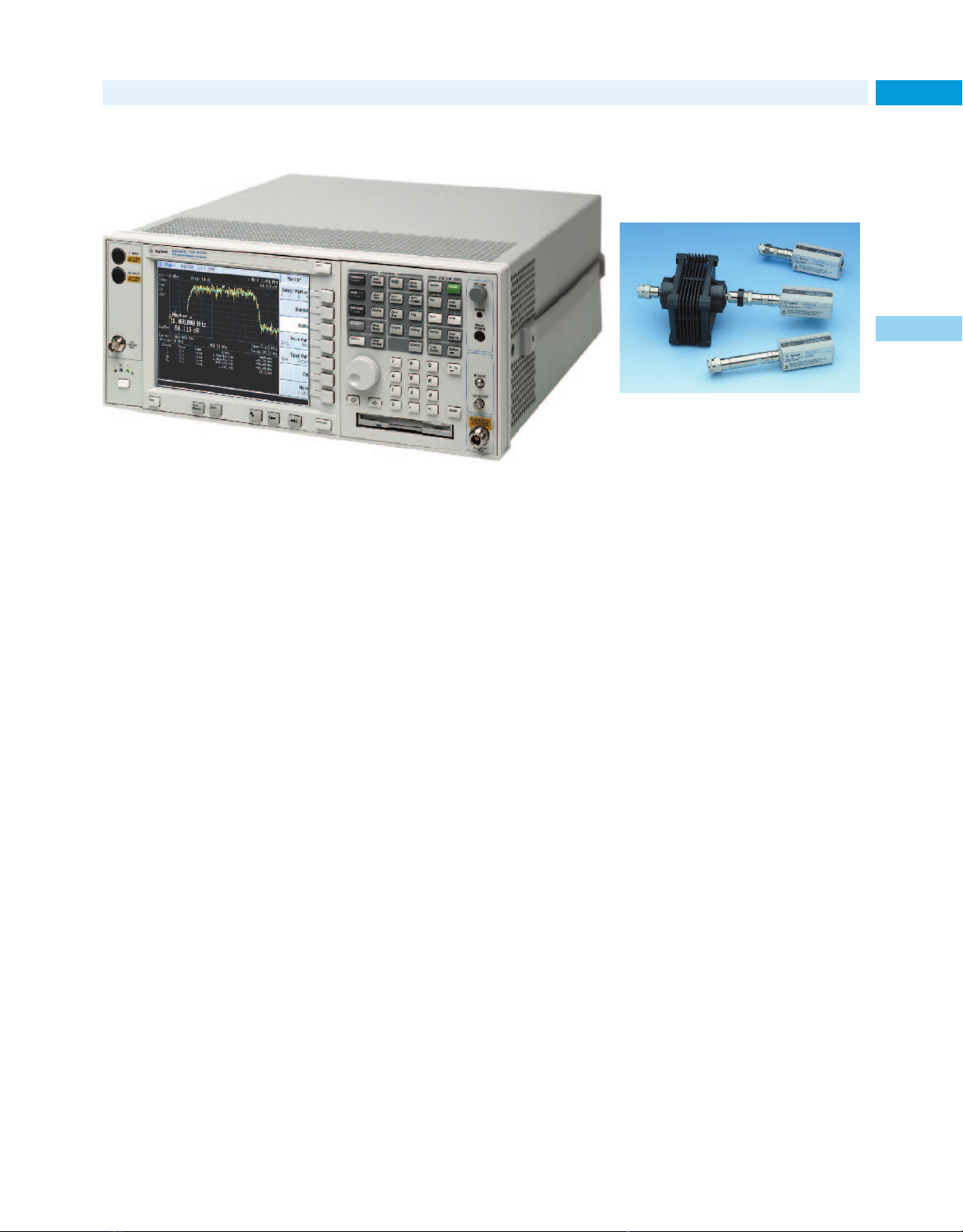
New Products for 2001
Performance Spectrum Analyzer (PSA)
The new spectrum analyzer has the speed, accuracy, and dynamic range you need to
analyze all the communication signals you encounter.
The Agilent Performance Spectrum
Analyzer is the first in a series of
modern, high-performance, signal
analysis tools. The analyzer measures and monitors complex RF and
microwave signals, providing comprehensive spectrum analysis for
communications systems and components. It gives you unprecedented
access to new levels of measurement
capability with optimized speed,
accuracy, and dynamic range for
every signal in your system.
Speed, accuracy, and resolution
Whether you are tuning oscillators
manually or performing high-volume,
automatic test on wireless products,
the Agilent PSA gives you a real-time
response. It offers state-of-the-art
speed in tuning and measurement
data transfer. Thus, the analyzer eliminates measurement bottlenecks to
help you meet time-to-market goals.
To reduce the tolerance required
in your measurement budget and
improve your product yields, you
simply increase the accuracy of
your measuring instrument. The
PSA has excellent specifications in
all aspects of amplitude accuracy:
absolute amplitude accuracy, log
fidelity, and resolution bandwidth
switching error.
Generally, it’s critical to use the correct resolution bandwidth for the
measurement being made. Resolution
that’s too narrow causes unnecessarily slow sweep speeds; resolution
that’s too wide causes a loss of signal
detail. The PSA optionally has 161
resolution bandwidths (1 Hz to
8 MHz). Optimize your measurements for speed or dynamic range.
Dynamic range and sensitivity
An analyzer with a wide dynamic
range lets you view small signals in
the presence of large signals without
introducing distortion products.
The excellent dynamic range of the
PSA is made even more useful by an
optional 2-dB step attenuator.
High sensitivity allows faster spur
searches and easier signal identification because wider bandwidths can
be used. The PSA has excellent sensitivity. If needed, you can boost that
sensitivity to exceptional levels by
using an optional preamplifier.
For more information, see page 231.
For detailed specifications, circle 16 on
the reply card (last page) or contact the
Agilent Call Center in your region (see
page 604).
RF & Microwave
Sensors for lowfrequency, high-power
measurements
The power sensors allow accurate lowfrequency/high-power measurements.
The Agilent E9304A power sensor
has a 9-kHz to 6-GHz measurement
frequency range. This power sensor
provides the low frequency coverage
required for electromagnetic compatibility (EMC) and electromagnetic
interference (EMI) test applications,
and they can also be used to measure
transmitter power and receiver sensitivity in the installation and maintenance of very low frequency (VLF)
to high-frequency (HF) radios.
You can make wide-dynamic-range,
high-power measurements with the
E9300H/01H (1 W, +30 dBm) and
E9300B/01B (25 W, +44 dBm) sensors.
Like all Agilent E-series power sensors,
the E9304A, E9300B/H, and E9301B/H
have their calibration factors stored
in EEPROM. They operate only with
the Agilent EPM and EPM-P series
power meters.
For more information, see page 304.
For detailed specifications, circle 17 on
the reply card (last page) or contact the
Agilent Call Center in your region (see
page 604).
49
1
Page 50
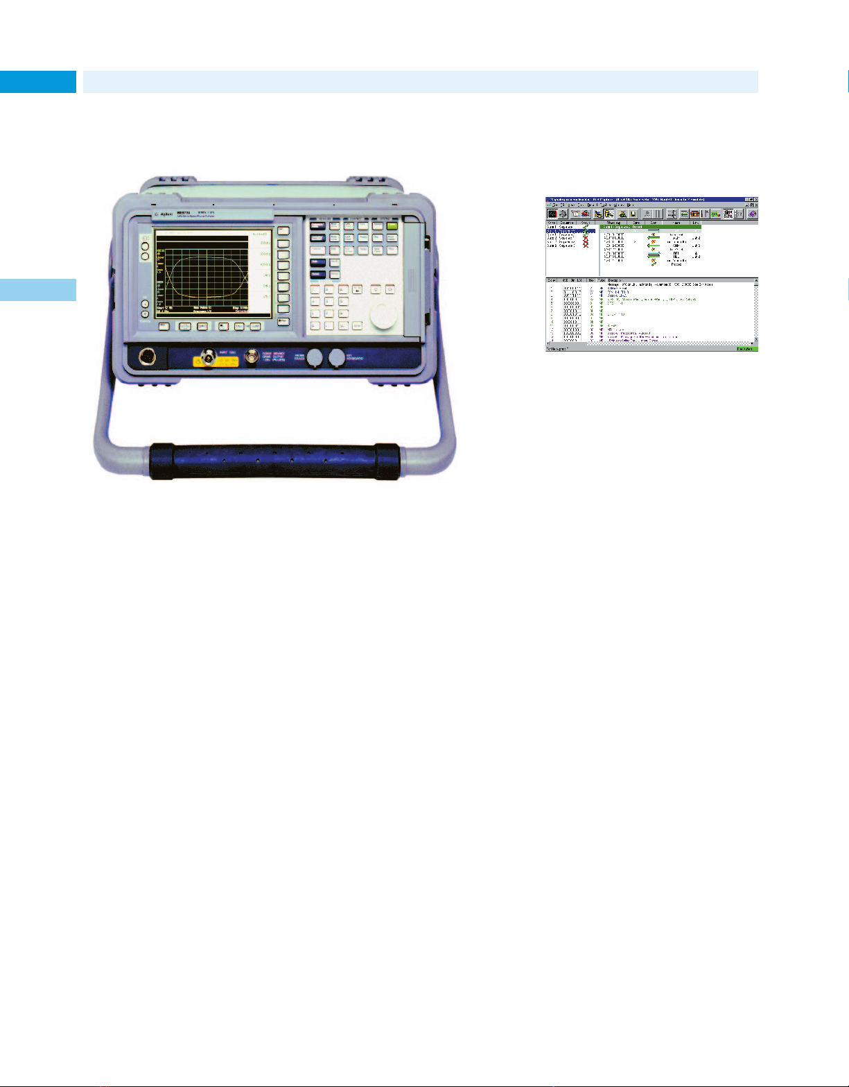
New Products for 2001
Communication Test
50
Easy, accurate, and repeatable noise figure
measurements with the NFA
1
Easy to set up and use, the NFA is a dedicated Noise Figure Analyzer that
lets you view the measurement data graphically.
Improve the design and manufacture of
your receiver components
Whether you’re working with systems, subsystems, subassemblies, or
discrete devices, each of your components add noise that affects the overall performance of a communication
design. By measuring and reducing
noise figures, you can give your components a competitive edge.
Comprehensively characterize your
device under test at a reasonable
cost. The NFA series analyzers offer
the traditional benefits of a noisefigure meter, plus the added features
and functions most often requested
by engineers and technicians:
• Easy measurement setup for
amplifiers and frequency converting
devices
• Color graphical display of noise
figure and gain versus frequency
• Low instrument uncertainty for
accurate noise figure measurement
The NFA series comes with a 3-year
warranty as standard.
Achieve more in less time
With an NFA series analyzer, you can
make better measurements, quicker.
It’s easier to set up measurements
correctly, view measurements in different formats, and print the results
or save them to disk. On-screen limit
lines simplify pass/fail testing.
Perform your measurements to the
latest, most exacting specifications
with extended frequency coverage,
high-performance features, and
selectable measurement bandwidths.
Repeatable, reliable measurements
provide results that you can trust.
These noise figure analyzers can help
you produce more robust designs
and prototypes in the lab. They can
also help you achieve higher yields
and throughput in manufacturing.
For more information see page 310.
For detailed specifications, circle 18 on
the reply card (last page) or contact the
Agilent Call Center in your region (see
page 604).
Graphical signaling emulation for acceptance and
interoperability testing
The optional add-on emulation tool is
fully integrated with Signaling Advisor’s
standard monitor capabilities.
The Agilent Emulite graphical emulation tool is a powerful addition to the
Agilent Signaling Advisor family—
testers that assist in testing SS7 and
related protocols in wireline and wireless telecommunications networks.
Ideal for acceptance, interoperability,
and start-up tests, or maintaining
services/equipment, the Emulite tool
significantly reduces the time to isolate and resolve signaling problems.
The tool uses decodes derived from the
signaling standards, so it produces
data that is helpful when arbitrating
solutions between vendors.
The Emulite tool’s easy-to-use graphical operation enables engineers to
avoid complex test programming.
Tests can be created or modified
easily, using the text used in the
standards. This lets engineers focus
on the content and sequencing of
signaling messages, and respond
more rapidly to signaling problems
or changing test requirements.
For more information, see page 403
For detailed specifications, circle 19 on
the reply card (last page) or contact the
Agilent Call Center in your region (see
page 604).
Page 51
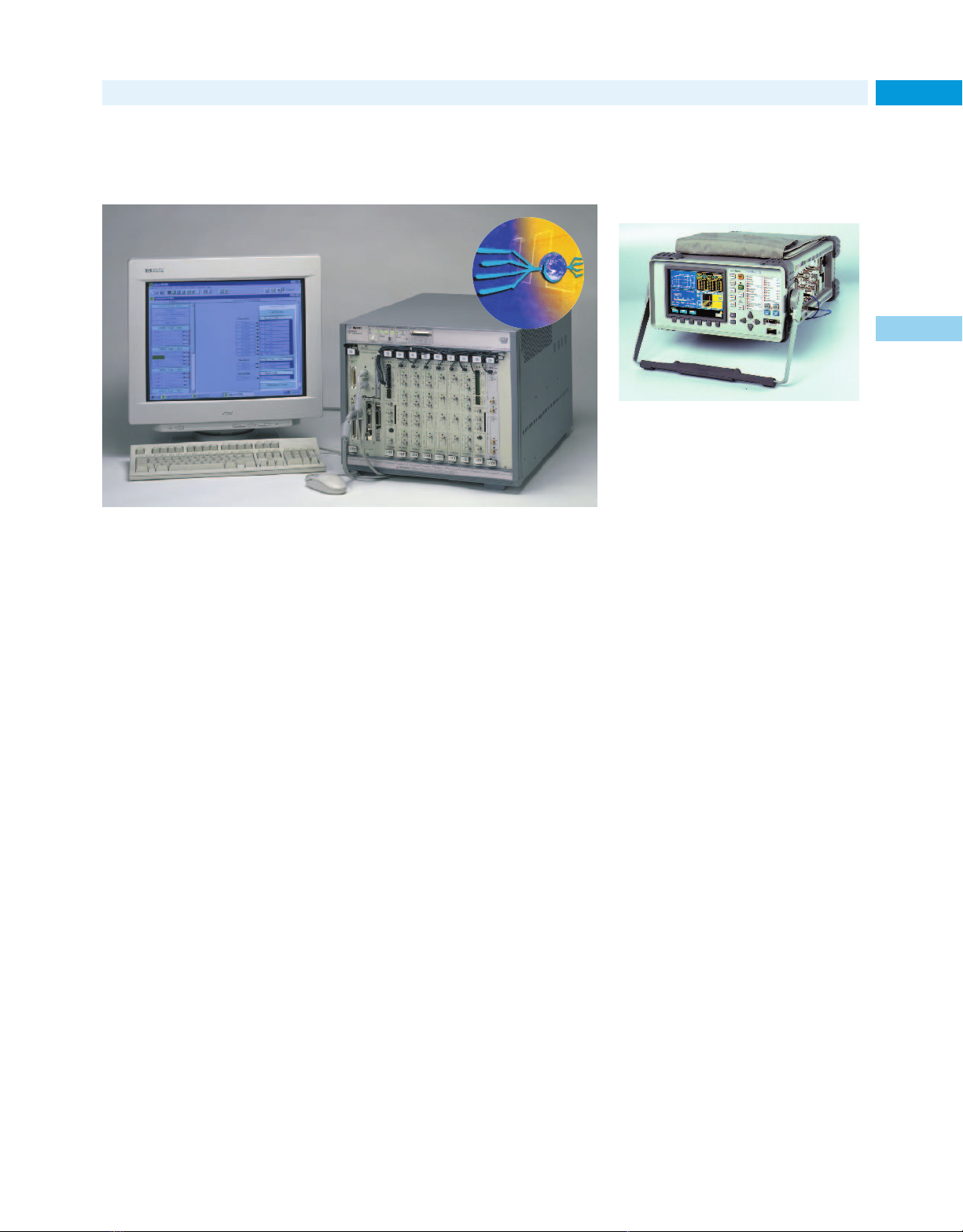
New Products for 2001
Parallel solution for testing high-speed digital
communication components
The tester has a fast, familiar user interface. You can tailor its flexible hardware to
fit your application needs.
The Agilent Technologies ParBERT
81250 is a modular parallel bit error
ratio (BER) solution for testing highspeed (up to 2.67 Gb/s) digital communication components such as
multiplexers/demultiplexers, FEC
devices, and transceivers/receivers.
If you are working on high-speed
communication ports, modules, or
devices, this system can help you
thoroughly test those products in
R&D and increase your throughput
in manufacturing. The tester offers
solutions for OC-48, OC-192, and
OC-768 testing.
Use the tester to generate pseudorandom word sequences (PRWS) and
user-defined and standard PRBS up
31
to 2
–1 on parallel lines. You can
analyze bit error ratios with userdefined data, PRBS, or mixed data.
This allows you to test devices with
several channels in parallel, saving
test time and cost.
The ParBERT 81250 offers data generation and analysis capabilities with
sequencing and looping, so you can
realistically stress your device under
test (DUT). Sequences can contain
memory-based (up to 8 Mbit) and/or
PRBS/PRWS data. The system can
generate and analyze single-ended,
low-voltage, and differential signals,
including true differential signals.
Thus, you can test devices based on
logic technologies such as LVDS,
ECL, and PECL.
Because the tester compares the data
from the DUT with the data you
expect and performs an analysis in
real-time, you view the BER while
the measurement is being made.
For more information, see page 405
For detailed specifications, circle 20 on
the reply card (last page) or contact the
Agilent Call Center in your region (see
page 604).
Communication Test
Perform fast, accurate
tests of SDH and SONET
devices to 2.5 Gb/s
The analyzer provides differential clock/
data interfaces for SONET/SDH BER
and jitter testing.
The Agilent OmniBER 725 communications performance analyzer offers
extensive measurement capability at
2.5 Gb/s, 622-Mb/s, 155 Mb/s and
52 Mb/s rates. It is ideal for manufacturers building components and modules for SDH/SONET network equipment. Optical and binary interfaces
allow testing where access to electrical clock and data signals is required.
The analyzer provides a range of bit
error ratio (BER) and jitter measurements, to ITU-T/Bellcore standards,
so the error and jitter performance of
modules can be thoroughly verified
before integration into operational
systems.
To rigorously test fiber-optic transmitter and receiver modules, the
OmniBER 725 is equipped with concatenated payloads for testing the
entire signal structure. This is vital
for representative jitter testing. In
addition, the analyzer can generate
unframed pseudo-random binary
sequence (PRBS) test patterns to help
ensure error-free device performance.
For more information, see page 412
For detailed specifications, circle 21 on
the reply card (last page) or contact the
Agilent Call Center in your region (see
page 604).
51
1
Page 52
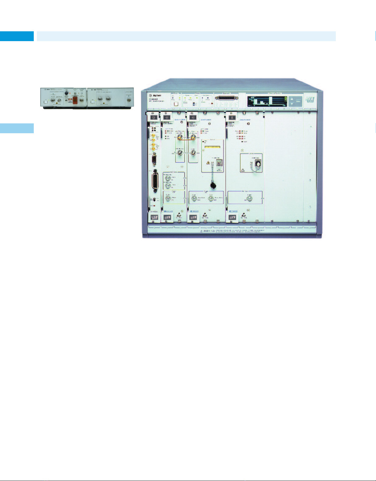
New Products for 2001
Communication Test
52
10-Gb/s optical interfaces
provide complete link for
BER testing
The transmitter/receiver combination
create a complete optical link for
system testing or optical fibers test.
1
The Agilent 83433A optical transmitter and 83434A optical receiver combine to provide a complete optical
link for BER testing 10 Gb/s SONET/
SDH and IP optical links and networks. They can also be used for
substitution testing of commercial
transmitters and receivers.
The 83433A transmitter handles a
wide range of input signal levels in
varying environmental conditions.
When combined with the Agilent
71612B error performance analyzer,
the transmitter produces high-fidelity, low-jitter waveforms for STM-16/
OC-48, STM-64/OC-192, and other
transmission rates from 2.4 Gb/s
through 10.7 Gb/s.
The 83434A receiver detects optical
signals at levels down to –16 dBm.
For eye diagram analysis, the receiver
can trigger a scope at 9.953 Gb/s
to help ensure that the display
accurately represents all possible bit
combinations in the data stream.
For more information, see page 476
For detailed specifications, circle 22 on
the reply card (last page) or contact the
Agilent Call Center in your region (see
page 604).
Perform DWDM and SONET/SDH functional
tests to 10 Gb/s
Use the flexible, cost-effective testers for testing high speed DWDM, OXC, and
OADM communication systems.
Agilent’s family of SpectralBER testers
are flexible, cost-effective solutions
for testing DWDM, OXC, and OADM
communication systems. The modular
VXI-based testers handle 10 Gb/s,
2.5 Gb/s, and multi-rate (2488/622/
155 Mb/s Tx/Rx) applications, and can
be tailored to match a wide range of
current and future testing needs.
The SpectralBER testers have a high
test-port density enabling manufacturers to test systems with high
channel counts simultaneously for
fast, convenient throughput.
The testers can be used to perform
functional BER test of optical add/
drop multiplexers, optical translators,
transponders, and multi-channel
systems.
For more information, see page 410
For detailed specifications, circle 23 on
the reply card (last page) or contact the
Agilent Call Center in your region (see
page 604).
Page 53
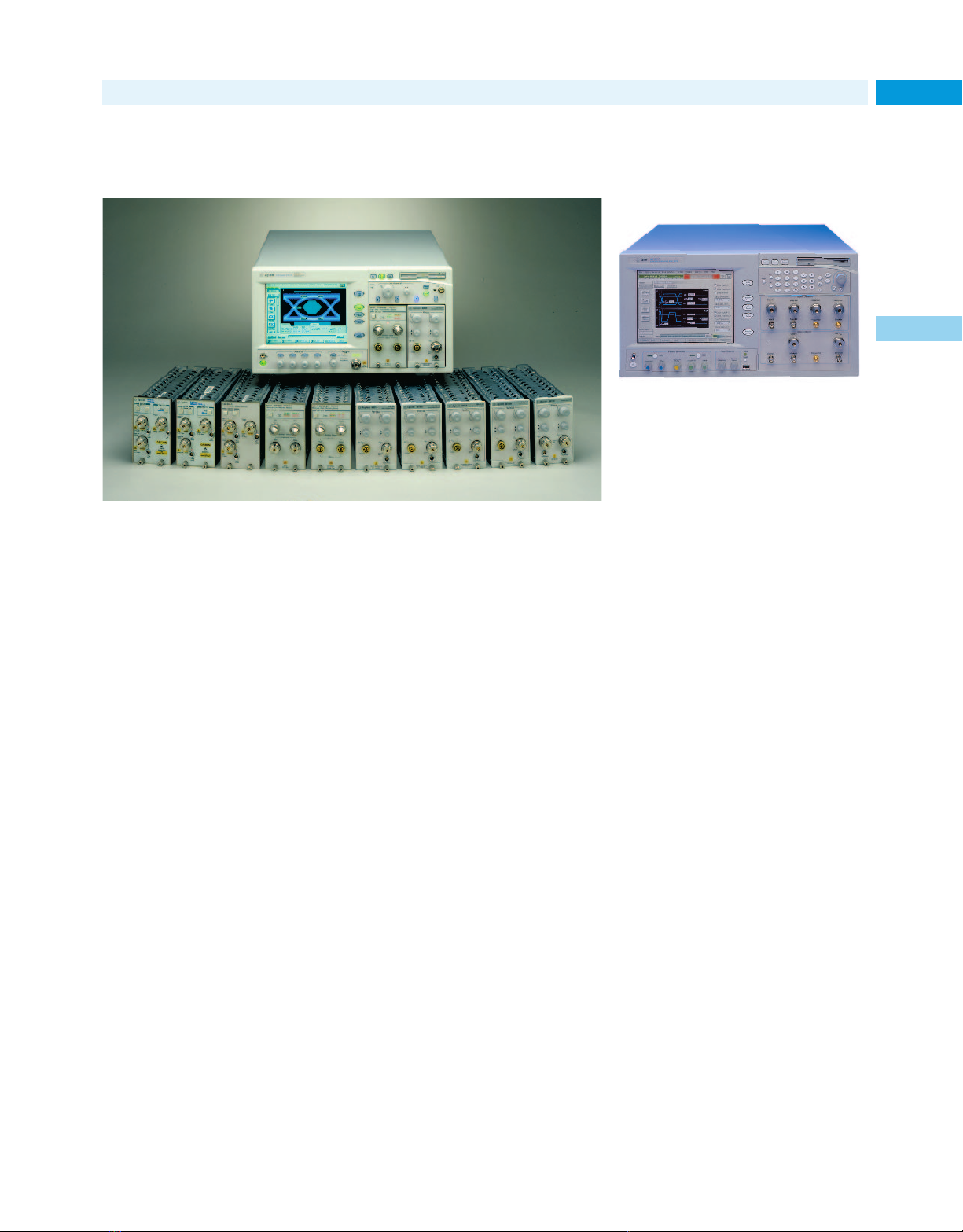
New Products for 2001
Digital communications analyzer performs complex
compliance measurements quickly and easily
Make compliance measurements just by touching one button on the Infiniium
DCA’s display screen.
The Agilent 86100A Infiniium DCA is
a high-speed, wide-bandwidth oscilloscope with digital communications
analysis capabilities. Simple to operate, it lets you complete complex compliance measurements in seconds.
Primary measurements are instantly
accessible. You can perform entire
procedures, such as compliance eye
analysis, with just a touch of the
screen. Whether you’re building components, systems or networks, the
Infiniium DCA’s measurements can
give you confidence that your transmitters meet industry standards.
Integrated optical, electrical receivers
Integrated optical and electrical
receivers provide high accuracy for
measuring and characterizing lightwave communications waveforms.
Integrated optical receivers cover
standard rates for SONET/SDH,
Gigabit Ethernet, and Fiber Channel.
Electrical receivers have 20-GHz or
50-GHz bandwidths. Filters are easily
switched in for compliance test, or
out for wide-bandwidth analysis. You
can also configure the 86100A for
the specific bandwidth filtering and
sensitivity you need.
The Infiniium DCA has a flexible,
modular platform, which allows new
firmware upgrades and modules to
be added in the future. It is also compatible with receiver modules used in
the Agilent 83480A and 54750A communications analyzers. Code used in
automated test systems designed
around the 84380A and 54750A can
be leveraged for use in the 86100A
with only minor modifications.
For more information, see page 121
For detailed specifications, circle 24 on
the reply card (last page) or contact the
Agilent Call Center in your region (see
page 604).
Communication Test
Powerful error analysis
for rapid problem
identification
Intuitive operation allows you to
concentrate on the problem—not the
test equipment.
The Agilent 86130A BitAlyzer—serial
bit error ratio (BER) tester—combines
an integrated pattern generator and
error detector to help you quickly
solve your design and manufacturing
problems.
• In the design environment, you
need to verify component performance and focus in on problems
quickly. The BitAlyzer’s intuitive
instrument setup gives you immediate visibility of settings, and produces an excellent waveform.
Significantly, it also provides powerful error analysis capabilities from
SyntheSys Research, which give you
clear insight into the underlying
causes behind error conditions.
• In manufacturing applications, you
can save test time by combining
the 86130A BitAlyzer with the
86100A Infiniium DCA. This combination of instruments allows
easy setup of BER measurements,
and fast go/no-go mask testing.
For more information, see page 406
For detailed specifications, circle 25 on
the reply card (last page) or contact the
Agilent Call Center in your region (see
page 604).
53
1
Page 54
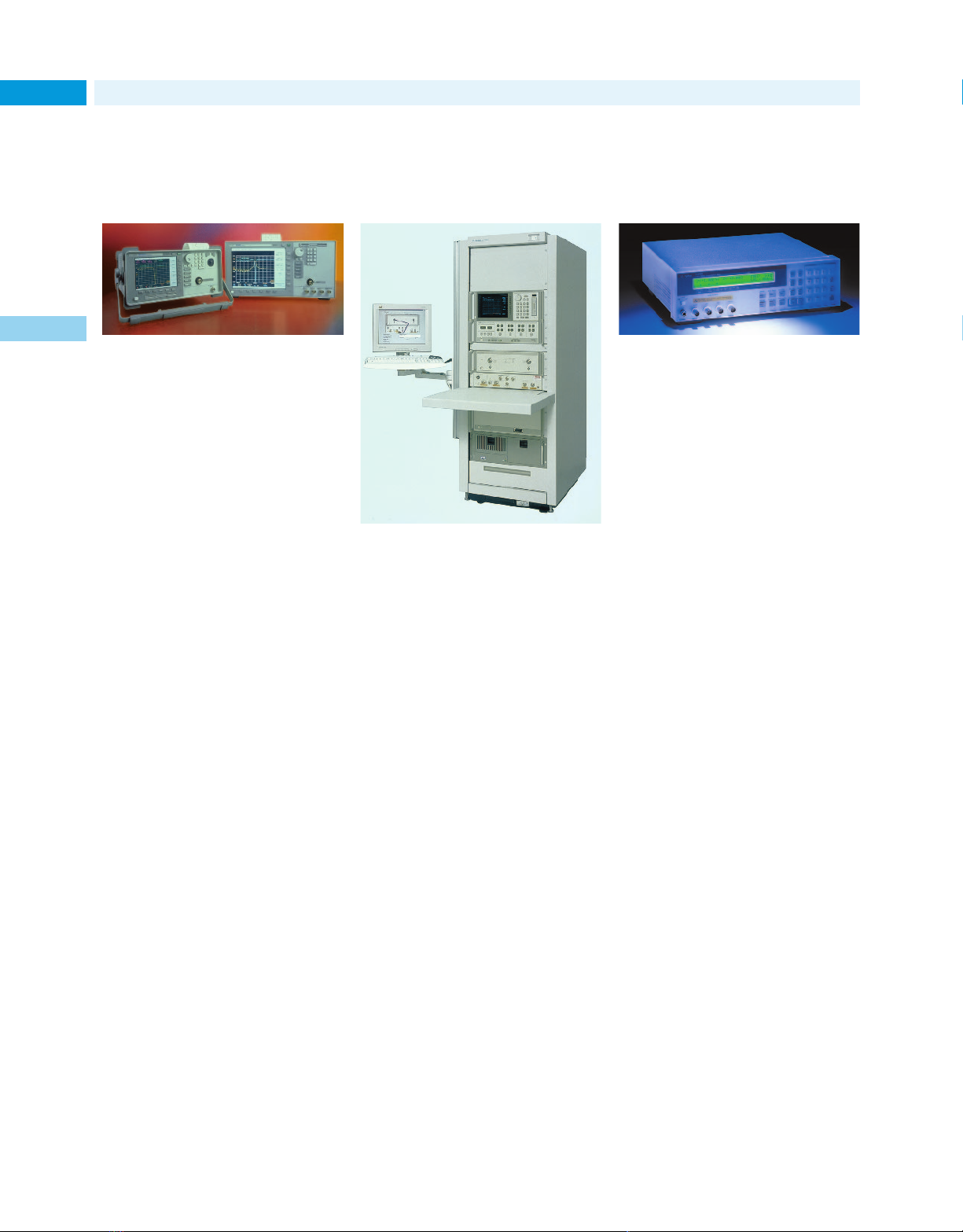
New Products for 2001
Lightwave/Component Test
54
Simplify the characterization of lightwave
components and systems
1
The DWDM channel analysis function
provides accurate power, noise, and
channel-wavelength measurements.
The performance capabilities, features
and built-in measurement applications of Agilent 86140B-family optical
spectrum analyzers (OSAs) simplify
the time-consuming tasks of characterizing optical components and systems. Each OSA includes a wavelength division multiplexing (WDM)
application with the patented dualsweep measurement technique, which
is the quickest way to measure and
record channel power, wavelength,
and optical signal-to-noise ratio.
Available in benchtop and portable
platforms, these OSAs have a remotecontrol capability for automated test
applications. They produce tabular
displays of channel wavelength,
power, OSNR, gain tilt, and peak-topeak power deviation. The data can
be viewed on the display, printed on
the built-in printer, or saved as CSV
files on the internal floppy drive.
One of the OSAs, the 86141B, has a
monchromator output and a power
meter function. The monchromator
output lets you isolate a single channel from a WDM signal or perform
other filter functions. The power
meter lets you maximize power
transfer in applications such as fiber
alignment, or make quick measurements of broadband optical power.
Accurately characterize
40-Gb/s optical
components
The 50-GHz lightwave component analyzer
characterizes the 40-Gb/s components
being developed for OC-768 applications.
Lightwave transmission systems
require accurate, repeatable characterization of their components to
guarantee high-speed performance.
The Agilent 86030A 50-GHz lightwave component analyzer accurately
and reliably characterizes the 40Gb/s components being developed
for OC-768 applications. The analyzer
measures the bandwidth of optical
receivers, and photodiodes. It can
also determine the bandwidth or
reflection of O/E (optical/electrical),
E/O, O/O, and E/E devices in magnitude and/or phase.
The 86030A lightwave component
analyzer uses a factory characterized
and calibrated internal O/E receiver
to provide calibrated measurements
of optical components. This lets
you verify that the devices you
design and manufacture meet
industry standards.
High-throughput capacitance meter for production environments
The capacitance meter enables higher
test throughput, while providing high
measurement accuracy.
The Agilent Technologies 4288A 1-kHz/
1-MHz capacitance meter is an optimum solution for high-speed production testing of the ceramic capacitors.
The meter offers improved measurement speed and accuracy with no
decrease in test efficiency. Several
features ease handler system integration: a built-in comparator that
sorts the measurement results into a
maximum of nine bins, an optoisolated handler interface, a GPIB
interface, and more.
For measurement systems that use a
component scanner, the capacitance
meter offers the optional scanner
compensation function. Error compensation can be performed independently for each scanner channel. This
minimizes not only the measurement
error in each channel, but also inconsistencies and the error in measured
values between channels.
For more information, see page 498
For detailed specifications, circle 28 on
the reply card (last page) or contact the
Agilent Call Center in your region (see
page 604).
For more information, please see page 472
For detailed specifications, circle 26 on
the reply card (last page) or contact the
Agilent Call Center in your region (see
page 604).
For more information, see page 478
For detailed specifications, circle 27 on
the reply card (last page) or contact the
Agilent Call Center in your region (see
page 604).
Page 55
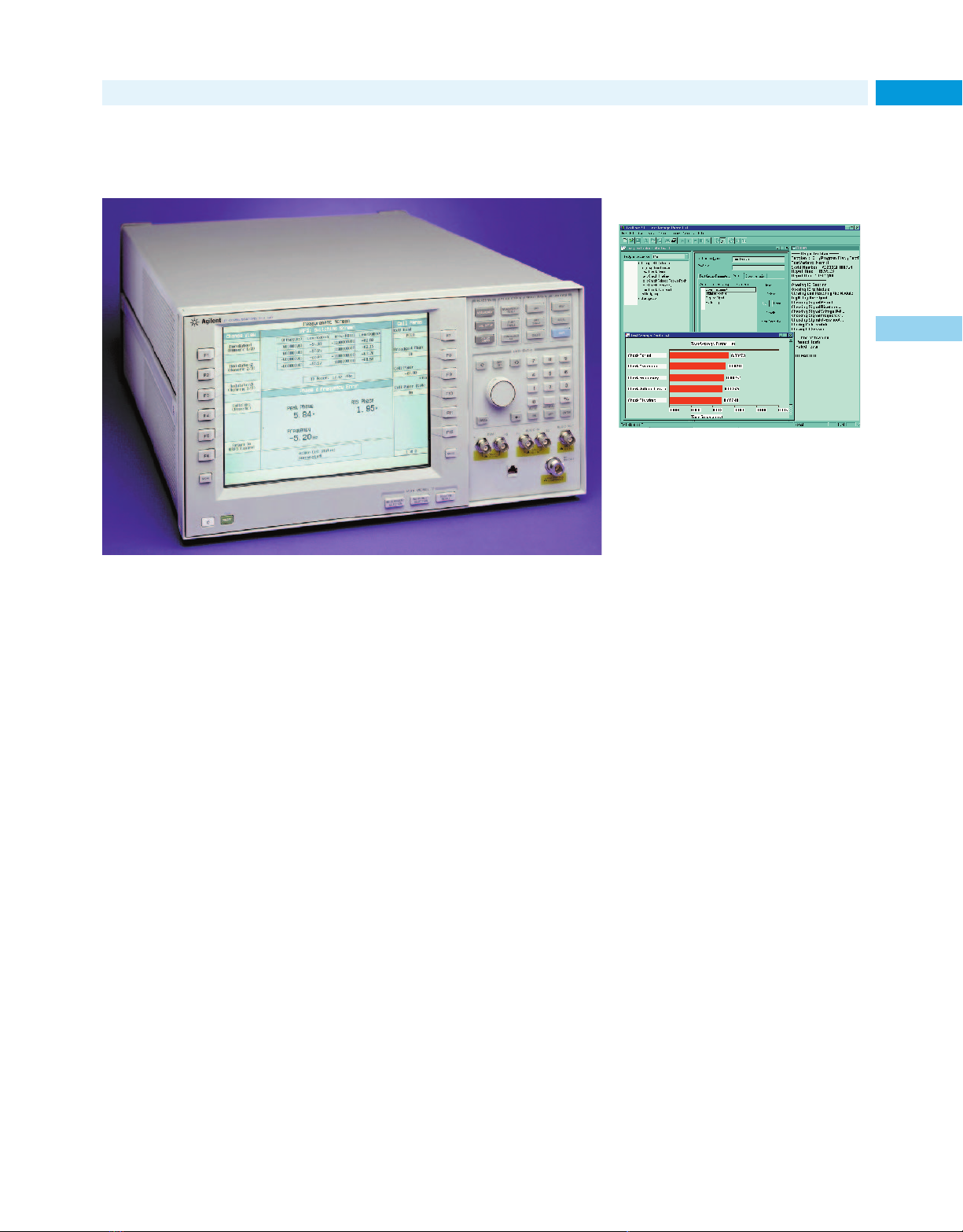
New Products for 2001
Multi-format mobile manufacturing test set helps you
meet your production goals
This wireless communications test set provides a competitive edge in high-volume,
automated mobile phone manufacturing test.
In high-volume mobile manufacturing,
test throughput and test yield are the
keys to meeting production output
goals. The Agilent Technologies 8960
Series 10 wireless communications test
set offers manufacturers immediate
competitive advantages. Developed for
high-volume, automated mobile phone
manufacturing test, the proven 8960
Series 10 offers speed, accuracy,
repeatability, multi-format capability,
ease of programming, and all in a format-flexible architecture. These features can help lower test costs and
raise production outputs.
The 8960 Series 10 test set can be
configured for GSM, GPRS, TIA/EIA136, and AMPS mobile phone testing.
IS-2000 mobile phone test with
multi-format capability will be added
mid year. Multi-format test capability
allows manufacturers to test multiformat phones with a single test set,
change production from one format
to another to meet changing demand,
or manufacture mobile phones with
different formats on the same line.
For the manufacturer, this means
faster response to market changes,
less downtime for changeovers, and
improved test set utilization.
Test IS-2000 mobile phones
A single-format version of the 8960
test set is available for early-tomarket IS-2000 mobile phone manufacturing test. The IS-2000 test mode
application provides IS-2000 testing
without call processing using mobile
phone test modes. This single-format
8960 test set will be upgradeable to
multi-format capability when IS-2000
call processing functionality is introduced mid year.
The test set’s format-flexible architecture is designed to grow with 3G
mobile phone technologies. Agilent
has designed the 8960 series 10 test
set to meet the needs of mobile
manufacturers now and into the
future. As mobile phone technology
advances, new formats will be added
and the hardware will be upgraded.
For more information, see page 363.
For detailed specifications, circle 29 on
the reply card (last page) or contact the
Agilent Call Center in your region (see
page 604).
Manufacturing Test
Test executive software
improves manufacturing
test productivity
The software offers rapid test system
development and a fast, simple-to-use
execution environment.
The Agilent E2011E TestExec SL
software platform helps test engineers improve their productivity. It
provides valuable usability tools that
enable them to spend less time writing software and more time running
tests. The software also helps manufacturers standardize their functional
testing. They can deploy the proven
E2011E test executive not only plantwide, but globally as well.
The TestExec SL software supports
the most popular test development
environments, including C/C++,
Visual Basic, Basic for Windows,
LabVIEW, LabWindows/CVI and
VEE. Usability tools such as the
Action Wizard, Test Profiler, and
Switch Manager aid system configuration and make it easier to optimize
system performance. The Throughput
Multiplier enables the system to test
multiple devices simultaneously
without the need to add hardware
or write custom software.
For more information, see page 86.
For detailed specifications, circle 30 on
the reply card (last page) or contact the
Agilent Call Center in your region (see
page 604).
55
1
Page 56
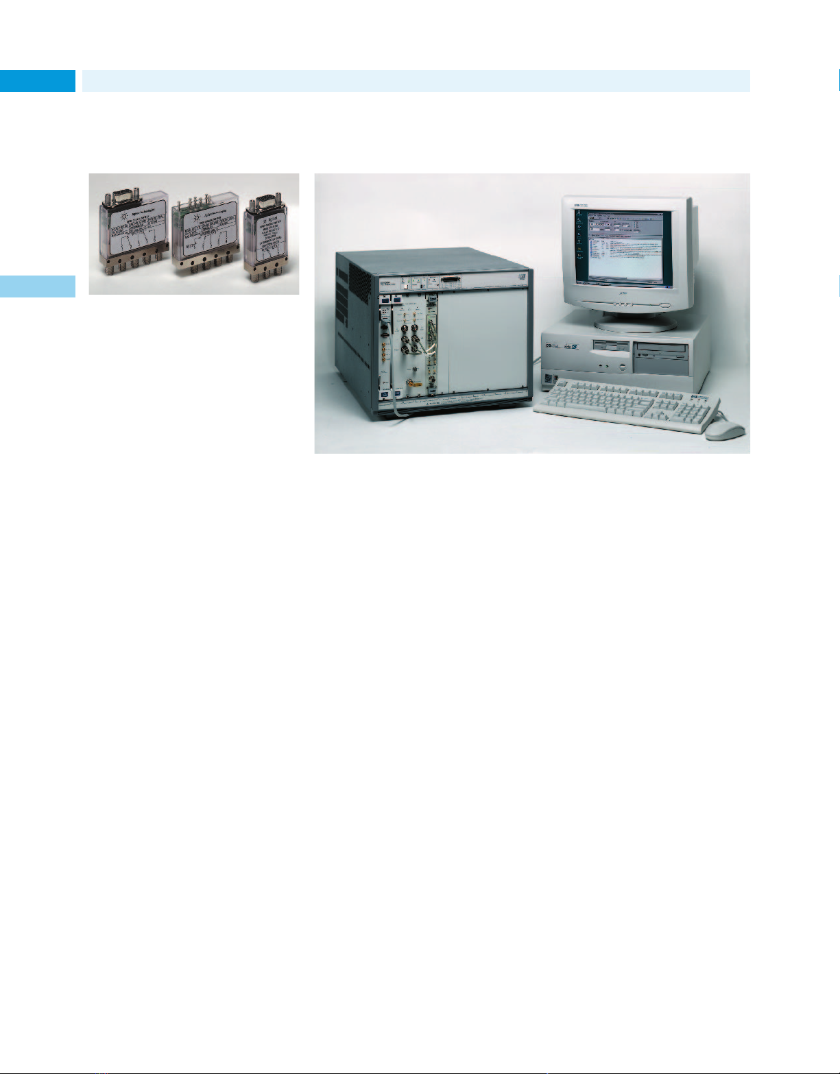
New Products for 2001
Manufacturing Test
56
High-reliability coaxial
switches
1
These electromechanical latching
switches reduce test system downtime
in high-volume wireless manufacturing
applications.
Agilent’s N1810 family of electromechanical latching switches combine
long life with excellent repeatability
and handle signals from dc to
26.5 GHz. Three-, four-, and five-port
switches are available, with and
without 50-Ω terminations.
These switches help reduce downtime
for your test platform by protecting
against failure and the need for recalibration after failed parts are replaced.
Agilent switches are designed to
meet warranted performance specifications throughout their entire lifetime. Reliability is a top priority.
The standard switch has a female Dsubminiature 9-pin connector. Solder
lugs are available as an option. Other
options include mounting brackets,
indicators, interrupts, TTL/5V CMOS
compatible drive, and your choice of
5-V, 12-V, or 24-V coil voltages. For
test platforms that require extra performance, some N1810-series switches offer higher isolation, lower SWR,
and reduced insertion loss.
Compact VXI subsystem is a high-throughput solution
for ATE applications
This analog signal generation and simulation subsystem is an excellent choice for
manufacturing test applications.
The Agilent E7501A is a compact, ATEoptimized stimulus subsystem for highthroughput stimulus/response measurements and high-performance signal
simulation applications. It combines
the modular components of a VXI
microwave synthesizer, a VXI baseband
arbitrary waveform generator, and
stimulus-focused software package.
The analog generation and simulation application software—a component of the Agilent Technologies
Signal Studio—provides an easy-
to-use interface that simplifies the
creation and delivery of arbitrarily
modulated signals.
The software also automates the process of characterizing and correcting
for ATE signal path effects for output
power and AM/FM characteristics.
For more information, see page 218.
For detailed specifications, circle 32 on
the reply card (last page) or contact the
Agilent Call Center in your region (see
page 604).
For more information, see page 319.
For detailed specifications, circle 31 on
the reply card (last page) or contact the
Agilent Call Center in your region (see
page 604).
Page 57
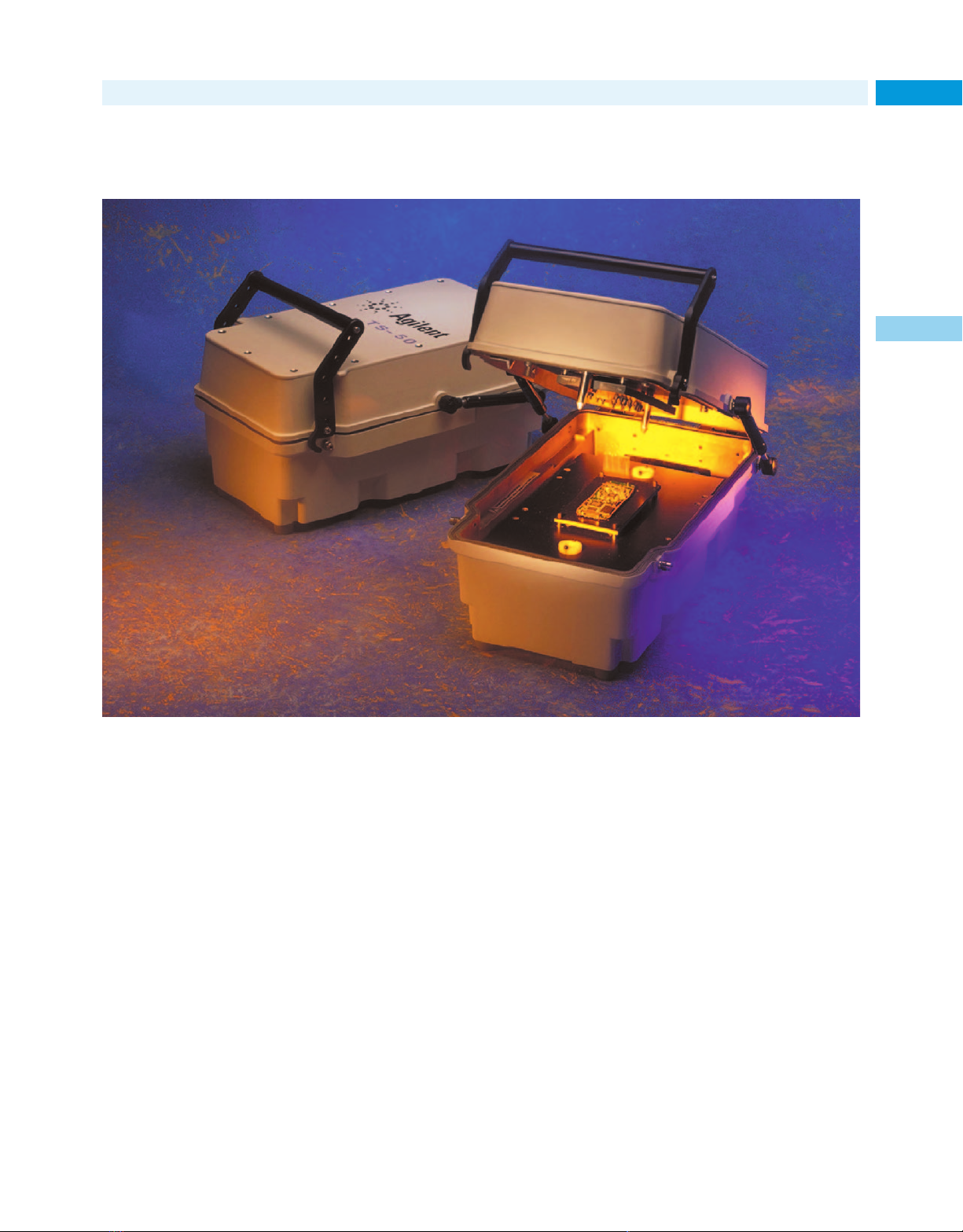
New Products for 2001
Manufacturing Test
Complete, high-quality test fixture solution for mobile phones and other
RF/wireless devices
57
1
These versatile kits simplify the development of test fixtures for RF/mobile phone products.
Products in the Agilent TS-50 series
are complete test fixtures in kit form,
containing the key components needed to create reliable, high-quality test
fixtures for RF/mobile phones. The
fixtures are highly versatile and
adaptable, designed to work optimally
with Agilent test equipment, and with
test equipment from other suppliers.
With these kits you can build a custom fixture for testing virtually any
assembled phone, RF device, or
phone PCB. The fixture can be reconfigured and used with other products. There is no need to design a
new test fixture for every new type
of phone. The board fixture can also
be reused by creating a new probe
plate with the appropriate pins.
Shielded Enclosure
Included in the TS-50 series is the
Agilent E8704B RF-shielded enclosure.
It can be used in testing many RF
devices, including assembled mobile
phones and the circuit boards and
components they contain.
For more information, see page 378.
For detailed specifications, circle 33 on
the reply card (last page) or contact the
Agilent Call Center in your region (see
page 604).
Page 58
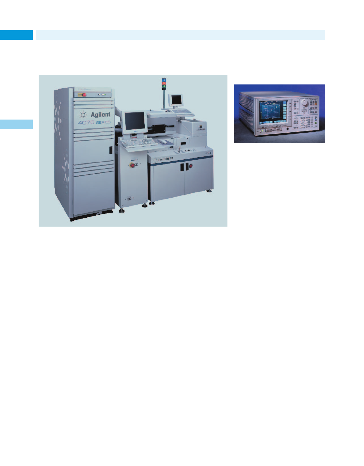
New Products for 2001
Semiconductor Test
58
Ultra-advanced parametric test solution aids fast
device development, improved process yields
1
The parametric tester has better measurement precision and resolution, an ultralow noise floor, and fast settling times for low-current measurements.
The Agilent 4073A is an ultraadvanced parametric tester. It is
designed specifically to meet the needs
of the leading-edge semiconductor
laboratories and fabrication lines
developing next-generation semiconductor devices. It builds on the performance and reliability demonstrated by the large installed base of over
2000 systems (4062 and 4070 family)
at major independent device manufacturers and wafer foundries, and
the many 4071 and 4072A testers
used in pioneering 300-mm wafer
fabrication facilities, worldwide.
The improvements implemented in
the 4073A were determined by system-on-a-chip (SOC) designs, copper
interconnects with low dielectric
materials, and other IC technology
trends. The new instrument can
handle advanced parametric tests, as
well as flash memory cell evaluations,
ring oscillator tests, and WLR tests. It
offers excellent performance with an
ultra-low noise floor, and has fast
low-current measurement settling
times and improved measurement
precision and resolution. Use it to
make DRAM cell evaluations that
require current measurement below
100 fA, for example. The 4073A is
also ideal for making resistance
evaluations of advanced Cu interconnects and for performing matching tests for new analog devices that
require measurement capabilities
<1 mV.
With this total testing solution, you
can quickly make both lower current
measurements and very low voltage
measurements in production environments. Tighten your measurement
guard bands and reduce your overall
cost of test.
For more information, see page 522.
For detailed specifications, circle 35 on
the reply card (last page) or contact the
Agilent Call Center in your region (see
page 604).
Semiconductor parameter analyzers: more performance and functions
The analyzers are complete solutions for
analyzing and evaluating semiconductor
processes and devices.
The Agilent 4155C and 4156C semiconductor parameter analyzers provide major improvements in both
measurement performance and functionality compared to the popular
4155C/56C models they replace. The
new analyzers are complete solutions
for analyzing and evaluating state-ofthe-art semiconductor processes and
devices. They offer the high accuracy,
high reliability, and measurement
flexibility that have made the 4155
and 4156 series the de-facto standards in the semiconductor industry.
Enhancements incorporated into the
4155C and 4156C analyzers include
a redesigned voltage measurement
unit with better resolution, an added
SMU quasi-static C-V measurement
capability (obtained using the ramp
voltage), and a brighter front-panel
LCD with a wider viewing angle.
For simplified benchtop system integration, the semiconductor parameter
analyzers allow interactive control
of the Agilent E5250A low-leakage
switching mainframe.
For more information, see page 523.
For detailed specifications, circle 36 on
the reply card (last page) or contact the
Agilent Call Center in your region (see
page 604).
Page 59
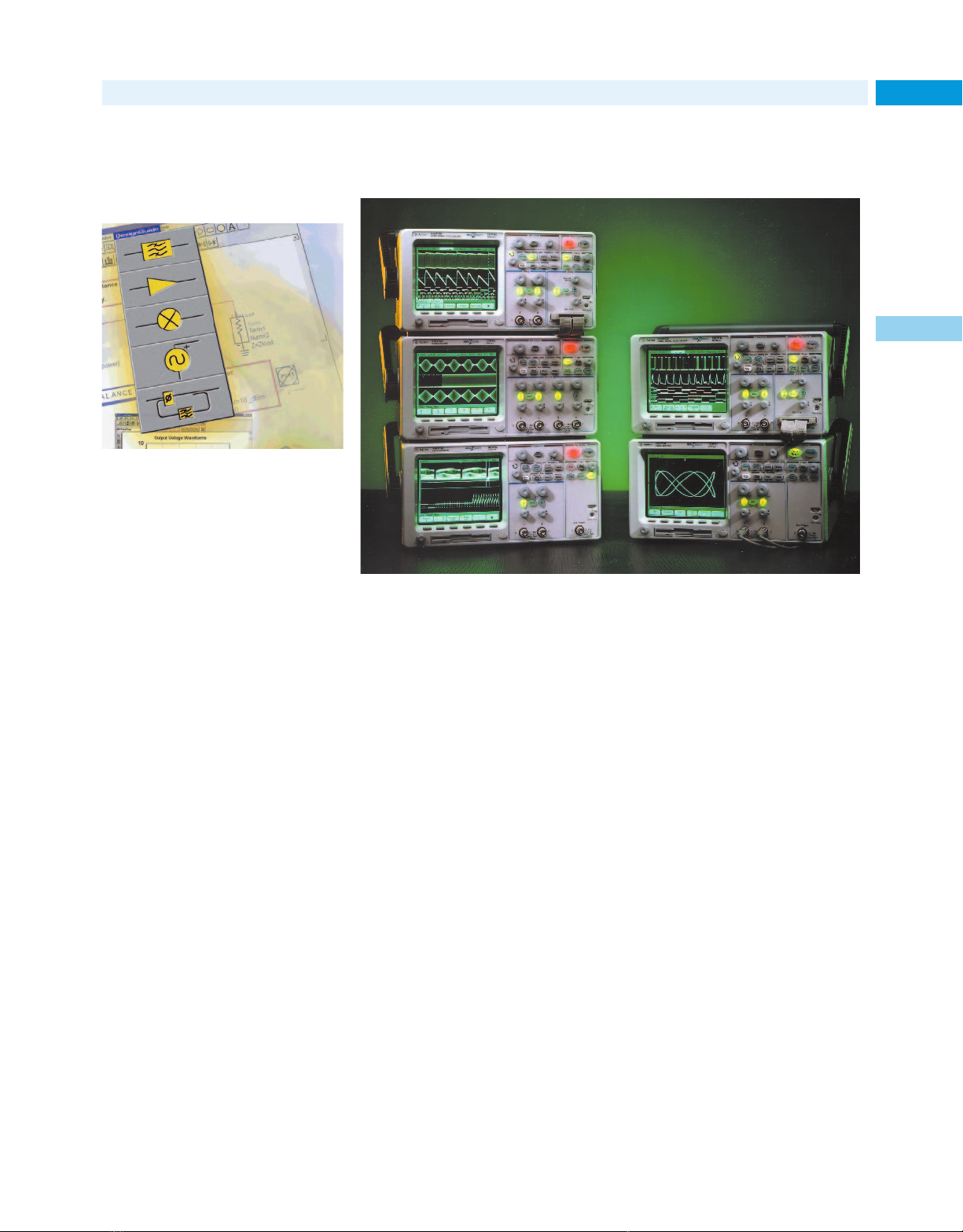
New Products for 2001
EDA tools make it easier
to use powerful simulation software
The application-specific expertise built
into the DesignGuides facilitates quick
product design and simulation.
Whether you are a new or occasional
user of the Agilent Advanced Design
System (ADS) unified design environment, or even an expert user who
must gain new design proficiency
quickly, you can benefit measurably
from the application insight built into
the DesignGuides series of EDA tools.
The first five DesignGuides cover
passive circuits (E5610A/AN), power
amplifiers (E5611A/AN), oscillators
(E5612A/AN), PLLs (E5613A/AN),
and linearizers (E5614A/AN). Other
guides are planned.
Each DesignGuide makes it easier to
apply the powerful simulation technologies of the ADS to a specific
design problem. It leverages the best
practices of industry experts, providing design aids such as predetermined
goals, predefined syntax, and preconfigured data displays. Now you can
access the capabilities of the EDA
environment without spending time
learning basic functions and creating
your own design aids. Save time and
get your products to market faster.
For more information, see page 84.
For detailed specifications, circle 37 on
the reply card (last page) or contact the
Agilent Call Center in your region (see
page 604).
Design Automation/General Purpose
Oscilloscopes help you capture and see subtle
signal details
The scopes have more channels, deep memory, a high-definition display, and
powerful triggering, so you can acquire and view important signal details you
might otherwise miss.
Today’s mixed analog and digital and
microcontroller-based system designs
are causing fundamental changes in
the capabilities needed in an oscilloscope. The five 60-MHz or 100-MHz
models in the Agilent 54620 series
address today’s requirements.
Two 2 + 16 channel mixed-signal
oscilloscopes (MSOs) combine 2 scope
channels with 16 logic channels to
show slow analog and fast digital signals simultaneously. The 4-channel,
100-MHz scope is ideal for applications with higher analog content. The
2-channel models deliver all the basic
56620-series benefits at value prices.
2 MB behind each channel
All models feature 2-MB MegaZoom
deep memory behind every channel.
This lets you easily look deep into
design interactions—capture long
time spans, then quickly zoom in to
look at details. The high-definition
display maps the deep memory into
32 levels of intensity on a screen
with superior horizontal resolution.
Now you can see subtle details never
before visible. The 54620 series
scopes respond instantly to control
or signal changes because they have
a fast update rate: 25 million vectors
per second.
The many other standard features in
all models include
• powerful triggering, including edge,
pulse width, pattern, and I
• RS-232 and parallel ports
• built-in 1.44-MB floppy drive
• automatic measurements and FFTs
• built-in Quick Help in 9 languages
For more information, see page 108.
For detailed specifications, circle 38 on
the reply card (last page) or contact the
Agilent Call Center in your region (see
page 604).
2
C
59
1
Page 60
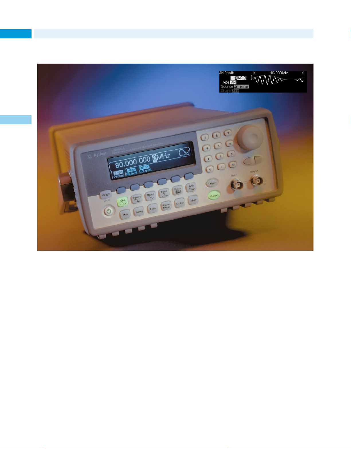
New Products for 2001
General Purpose
60
80-MHz function/arbitrary waveform generator with pulse capabilities
1
The 80-MHz function/arbitrary waveform generator provides standard, arbitrary, and pulse waveforms at an affordable price.
The Agilent 33250A improves on the
popular 33120A function/arbitrary
waveform generator, offering nearly
five times the performance. Its 80-MHz
bandwidth lets you handle more
diverse applications than ever before.
A wide variety of built-in signals,
custom arbitrary waveforms, and
higher-frequency pulse capabilities
(up to 50 MHz) help you tackle more
difficult testing challenges. Direct
digital synthesis (DDS) techniques
create stable, accurate output signals
with low distortion.
The generator’s color graphical display, softkey menus, and graph mode
work together to simplify the creation
of complicated waveforms such as
modulation. Follow the softkeys and
on-screen help to set up your waveform, then verify the results with
graph mode.
Standard features of the function/
ARB generator include sweep, burst,
modulation, and an external 10-MHz
clock reference, as well as GPIB
and RS-232 connectivity and a
3-year warranty.
The 33250A gives you great capability
and performance at a price less than
you might expect to pay for such an
outstanding instrument.
For more information, see pages 163.
For detailed specifications, circle 39 on
the reply card (last page) or contact the
Agilent Call Center in your region (see
page 604).
Page 61
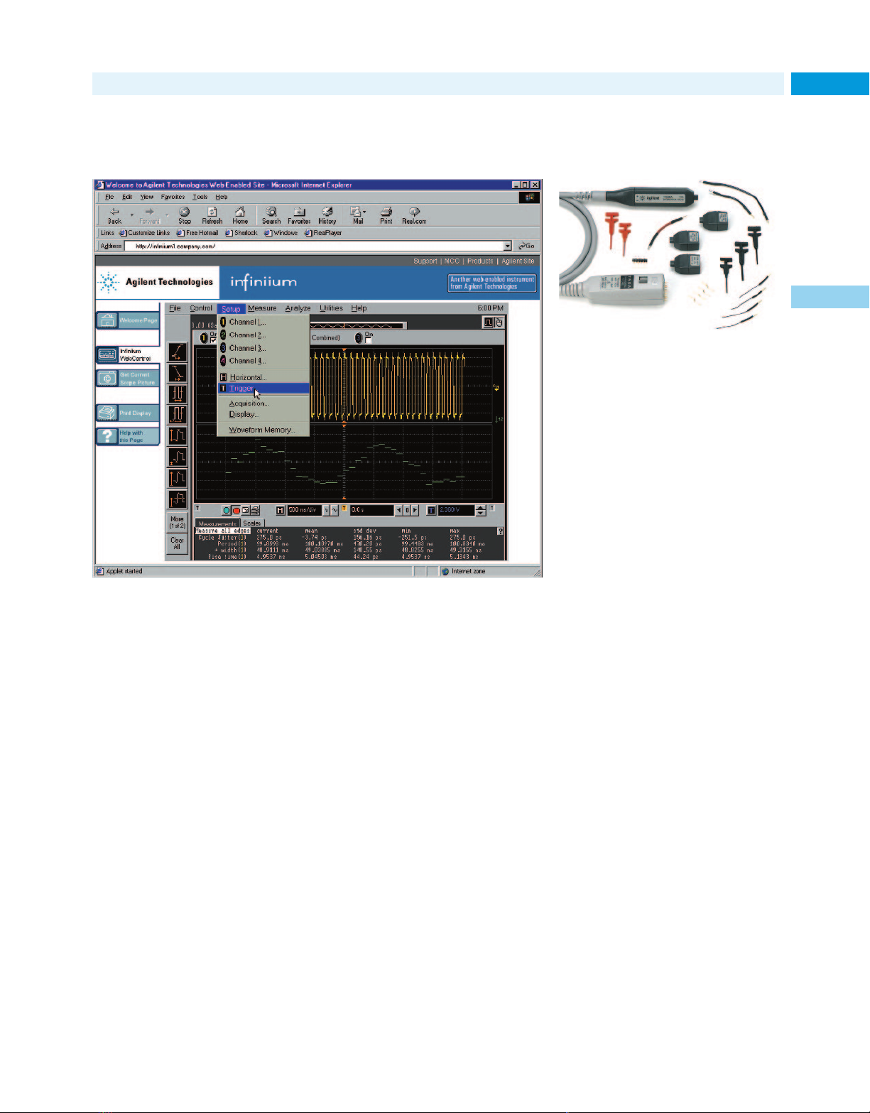
New Products for 2001
Software expands the capability and utility of
Infiniium-series scopes
General Purpose
High-bandwidth differential scope probes
Differential signal measurements are
easy to make: combine a differential
probe and an Agilent Infiniium scope.
The Agilent 1154A and 1159A highbandwidth differential probes are
valuable accessories for Infiniiumseries scopes. The 1154A has
500-MHz bandwidth. Its 10X gain
and 10:1 attenuation allow a maximum of 100:1 attenuation. The
1159A offers 1-GHz bandwidth and
1:1 attenuation, making it ideal for
use with fast, low-voltage signals.
61
1
Features of the software—Web-enabled and GPIB-over-LAN connectivity, e-mail on
trigger, and an enhanced measurement package—can make your job even easier.
The latest software for the Agilent
Infiniium scopes, Version 4.0, can
make your job easier because it offers
• Web-enabled connectivity
• GPIB over LAN capability
• e-mail on trigger capability
• enhanced measurement functions
(some functions available only on
model 84845A or higher)
The software’s Web-enabled connectivity feature allows you to remotely
display and control your Infiniium
scope from any Java-enabled Web
browser over the scope’s built-in
LAN interface. You can also send
GPIB commands over a LAN to control your Infiniium scope or set it up
to send an e-mail with a bit map of
the display screen when the scope
triggers on an intermittent event.
Now you don’t have to be in your lab
to view and control the instrument!
The enhanced measurement package
includes additional waveform math
functions that allow you to plot measurement results as a function of time,
the ability to compute statistics on
a suite of measurements, and more.
The Version 4.0 software is now
included in all six Infiniium-series
scopes. It is also is available free to
owners of Infiniium scopes; contact
your Agilent sales office or
visit our website:
www.agilent.com/find/infiniium_software
For more information on Infiniium, see
page 116.
For detailed specifications, circle 40 on
the reply card (last page) or contact the
Agilent Call Center in your region (see
page 604).
The 1154A and 1159A have an input
resistance of 1 MΩ and a low input
capacitance (<6 pF) to minimize circuit loading. The CMRR is >40 dB at
10 MHz for 1154A, and >19 dB at
500 MHz for the 1159A, without
external attenuators connected.
The probes have external ac coupling,
which eliminates dc and simplifies
measurements of ac voltage. Their
high gain and low input capacitance
make them ideal choices for viewing
single-ended signals.
For more information, see page 129.
For detailed specifications, circle 41 on
the reply card (last page) or contact the
Agilent Call Center in your region (see
page 604).
Page 62
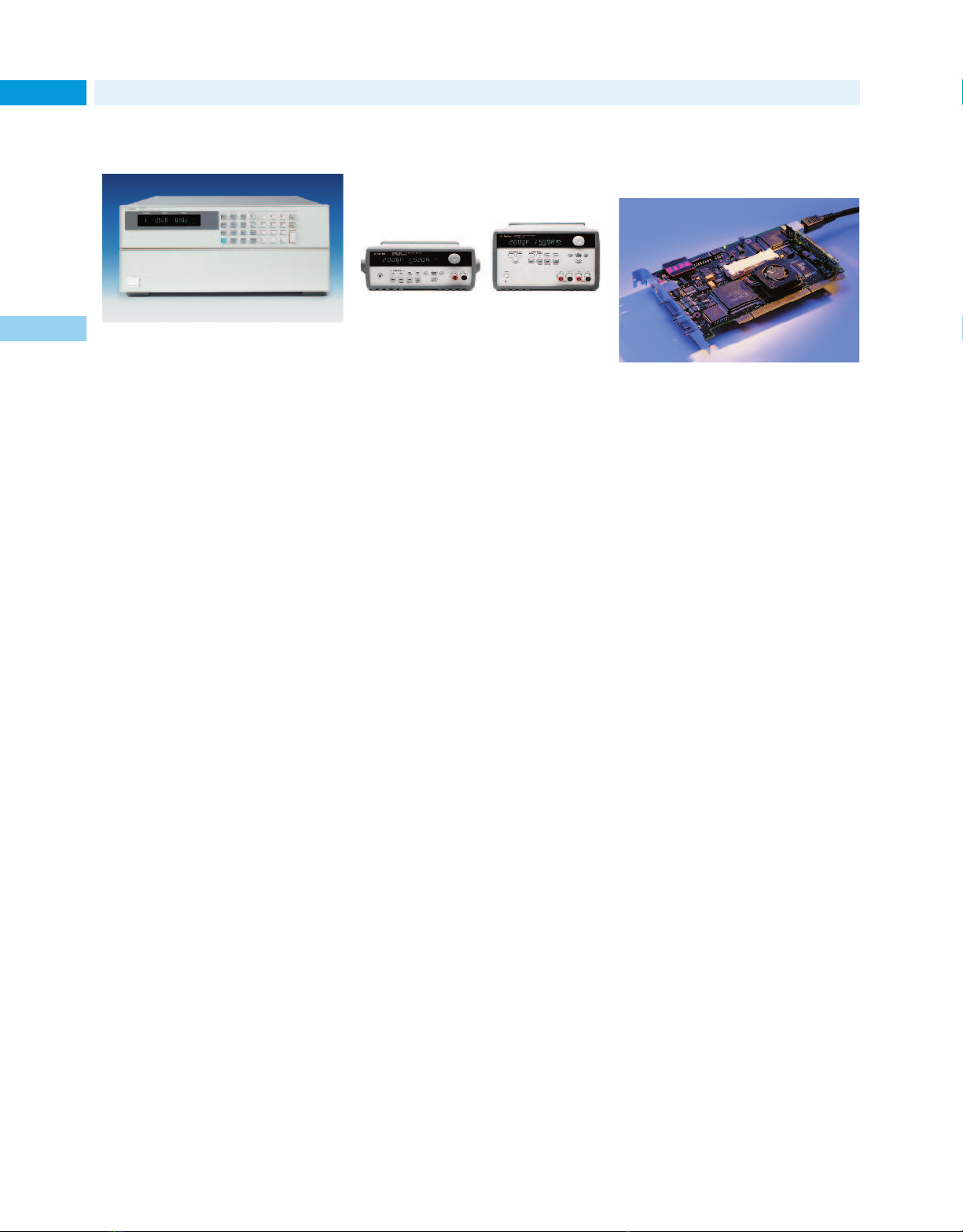
New Products for 2001
General Purpose/Digital Design & Debug
62
Fast electronic loads
1
High-speed electronic loads provide significant throughput gains for dc power
supply test systems.
The high-speed electronic loads in
Agilent’s N3300A series provide significant operating speed improvements. They also have additional features that allow further reductions
test time and additional gains in system throughput.
The loads have a modular design that
is easy and flexible for system configuration. Up to six load modules
can be installed in one mainframe.
Improved programming accuracy is
provided in all operating modes with
16-bit D/A converters and lower output ranges. Similar accuracy
improvements have also been made
to the built-in measurement system,
which provides many advanced capabilities formerly available only by
adding extra equipment. Each module contains a DMM and a digitizer
that can make simultaneous voltage
and current measurements.
For more information, see page 166.
For detailed specifications, circle 42 on
the reply card (last page) or contact the
Agilent Call Center in your region (see
page 604).
Affordable dc power
supplies with programming interfaces
This expanding family of power supplies
provides 30 W to 100 W of clean, stable
power at affordable prices.
The six new Agilent E3640A series
dc power supplies deliver 50-W and
80-W single outputs, and 60-W and
100-W dual outputs. Each comes
standard with GPIB/RS-232 interfaces and full programmability support. The dual-output models provide
two isolated power supplies and can
display two voltages or currents
simultaneously.
For manual testing or automated test
system applications, these reliable,
low-cost supplies are easy to use and
provide excellent value. All models
deliver clean, reliable power with
dependable regulation.
The E3640A series gives you the flexibility of dual output ranges and an
easy-to-read vacuum fluorescent dual
display. Front-panel and rear-panel
output terminals simplify setups. The
output load is protected against overvoltage. SCPI programming and free
software drivers for the Agilent VEE
and National Instruments LabView
environments ease integration into
automated test systems.
For more information, see page 188.
For detailed specifications, circle 43 on
the reply card (last page) or contact the
Agilent Call Center in your region (see
page 604).
PCI-X verification
solutions
The exerciser/analyzer and target
master card aid the development of
PCI-X devices.
The Agilent E2929A PCI-X exerciser/analyzer and the E2922A PCI-X
master target card ease the testing
and verification of computer devices
and subsystems that use 133-MHz
PCI-X I/O bus technology.
The exerciser/analyzer combines a
PCI-X protocol checker, an exerciser
that generates PCI-X transfers, and a
PCI-X state logic analyzer. (A logic
analyzer adapter from Future Plus
adds PCI-X protocol check and analysis capabilities to Agilent 16700series logic analyzers). Software
included with the E2929A addresses
the needs of design development, validation, and compliance testing.
The master target card has just the
PCI-X exerciser and protocol checker
capabilities. It’s operated by the
C-API through the PCI-X interface,
and integrates easily into test environments. An optional designverification test library (E2977A)
contains transaction-level tests and
data-level stress tests.
For more information, see page 440
For detailed specifications, circle 44 on
the reply card (last page) or contact the
Agilent Call Center in your region (see
page 604).
Page 63
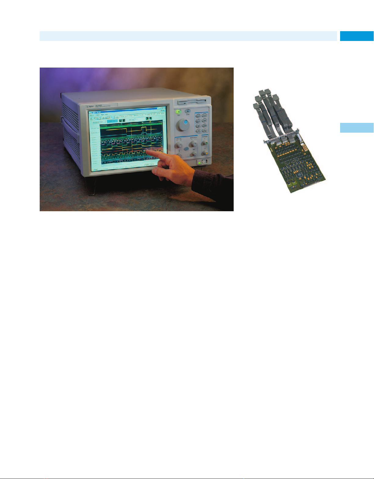
New Products for 2001
Digital Design & Debug
Powerful, flexible, easy-to-use logic analysis system 300-MHz pattern generator
module enhances logic
analyzer family
With this digital pattern generator, you
can check your prototype quickly, using
Access the 16702B logic analysis system’s powerful measurement and analysis
capabilities via an intuitive user interface.
The Agilent 16702B logic analysis
system has a large touch screen display that provides quick and easy
access to key logic analysis functions
and displays, as well as simultaneous
views into system activity. Hot keys
give instant access to the most frequently used displays, while the frontpanel knobs provide a quick and
intuitive way to change vertical and
horizontal scaling, move markers,
scroll through data or waveforms,
or change the values of variables.
Powerful measurement and analysis
capabilities, combined with the flexibility of a modular system, let you
customize a logic analysis system to
your specific needs. Multiple, timecorrelated views of system behavior
(from analog signals to source code)
let you view symptoms in the domain
best matched to the problem.
Available measurement modules for
the 16702B system provide
• up to 8160 channels of logic analysis
• state clock speeds up to 400 MHz
• timing analysis sampling up to
2 GHz
• state/timing memory depth up to
32M samples
• oscilloscope bandwidth up to
500 MHz
• pattern generator clock speeds
up to 300 M vectors/s
• pattern generator memory depth
up to 16M vectors
• emulation capabilities
For more information, see page 449.
For detailed specifications, circle 45 on
the reply card (last page) or contact the
Agilent Call Center in your region (see
page 604).
only one instrument.
The Agilent 16720A digital pattern
generator module—part of the 16700series logic analysis system—is an
ideal tool for performing functional
tests on your digital design. Check
the functional characteristics of your
prototype, and see how your target
responds to specific signals or clock
speeds. In automated test environments, use the pattern generator to
run design verification tests quickly,
with only one instrument. Configure
up to 240 stimulus channels in one
Agilent 16700-series mainframe.
If you need memory depth on your
vector sequence, the pattern generator provides up to 16M vectors of
stimulus memory. Now you can program your most extensive and complex vector patterns into this test
instrument to exercise your device
under test in the most difficult application environment. Offering speeds
as high as 300M vectors/s, the
16720A is a key signal source solution for high-performance digital
debug and verification.
63
1
For more information, see page 453.
For detailed specifications, circle 46 on
the reply card (last page) or contact the
Agilent Call Center in your region (see
page 604).
Page 64
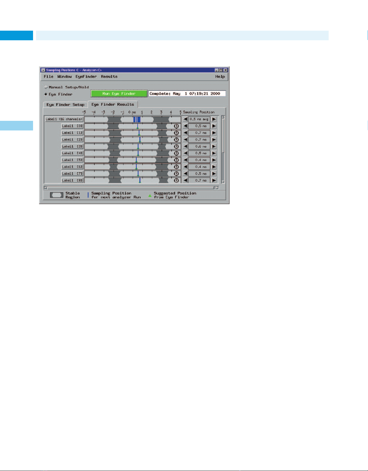
New Products for 2001
Digital Design & Debug
64
Make reliable state measurements on high-speed buses
1
Agilent’s eye finder examines the signals coming from the circuit under test and
automatically adjusts the logic analysis setup and hold window on each channel.
• hardware enhancements that allow
you to rapidly analyze large data sets.
• Eye finder technology, which automatically adjusts the setup and
hold times on every channel with
100-ps resolution. This technology
eliminates manual adjustments and
gives you the highest confidence in
accurate state measurements on
high-speed buses.
• 2-GHz timing analysis, with simultaneous state and timing data
available through a single probe
connection, across all channels,
all the time.
• VisiTrigger technology, which combines powerful trigger functionality
with a graphical user interface that
is easy to understand and use.
• High channel count. You can configure up to 340 channels in one
Agilent 16700-series mainframe, or
up to 5440 channels in a multiplemainframe setup.
The Agilent 16750A, 16751A, and
16752A logic analysis modules deliver the performance needed to develop and debug the complex, highspeed digital designs of next-generation computers, networking equipment, and communications systems.
The analysis modules provide
• 400-MHz state speed, which is
critical for accurately capturing
state data at full speed on highspeed data buses.
• memory depth up to 32M samples,
so you can capture the clues needed
to solve difficult and hard-to-reproduce problems.
For more information, see page 450.
For detailed specifications, circle 47 on
the reply card (last page) or contact the
Agilent Call Center in your region (see
page 604).
Page 65

You’ve read the book, now see the Web site.
www.agilent.com/find/tmc
Test & Measurement
catalog
2001
The industry’s most prestigious online test and
measurement resource is at your fingertips: The
Agilent Technologies website. All the information
you need to research, locate and purchase the test
equipment you want.
Including:
Extensive product/application information:
• Datasheets
• Manuals
• Application notes
• Tutorials
• FAQ’s
• Interactive demonstrations
• Comparative product data and evaluation tools
• Free software
Keep yourself up-to-date:
• News about special promotions, events, and
T&M education courses
• A technical forum
• Obsolete product replacement recommendations
• Alternative purchasing plans
Now faster and easier than ever:
• Access to customer support services
• Information in your local language*
• Prices in your local currency*
• Agilent product order status reports
It’s the only web site that can live up to the catalog –
and your needs. Bookmark it today and visit often!
Footnotes:
*Availability of this feature may be limited; an expansion program is ongoing.
For best results, view the Agilent website with Microsoft’s Internet Explorer
browser.
www.agilent.com/find/tmc
Page 66

2 Support & Services
66
Product Support, System Integration, Consulting and Training Services
At Agilent,
Our service and support promise
is simple: We maximize value,
minimize risk, and eliminate
headaches over the life cycle
of your test and measurement
equipment.
Call today to learn how our
promise works to your advantage.
Page 67

Support & Services 2
Product Support, System Integration, Consulting and Training Services
Quick Selection Guide 68
Our Promise and Your Advantage 69
Hardware and Software
Support Services 70
Success Story:
Lucent Technologies 73
System Integration Services 74
Success Story:
Henkel Waschmittel GmbH 75
Consulting 76
Training and Education 77
Success Story:
Microelectronics
Technology, Inc. 78
67
“
Tyco Submarine Systems, Ltd. expressed
confidence in our capabilities to deliver
timely technical service and support at
each of the 15 landing stations.
Jim Young, Agilent U.S. Field Operations
”
Channel Partners 79
Page 68

Support Overview
68 Quick Selection Guide
Agilent support services: How can we help?
Whether you need a fast answer about equipment operation or a factory full
of custom test systems, Agilent’s service and support team is ready to help.
We’ve built a comprehensive set of services with one goal in mind: giving you
the tools and information you need to succeed on the job, no matter what
your job may be.
Contacting Agilent for support
The Agilent T&M web site is a growing source of online support information,
available 24 hours a day, 7 day a week. We recommend you start there. If you
do not find your answer, click on “Assistance” to find the easiest way to contact Agilent for help.
Web: www.tmo.agilent.com
2
No access to the web? In the US:
Phone: 1-800-452-4844
For fax and email, request a form by calling 1-800-452-4844.
For all other locations, please refer to page 604 for your nearest Agilent office.
Our Promise: Delivering on expectations
We want your Agilent equipment to deliver the performance you expect. If
you need assistance, we provide a range of support from verifying proper
operation to clarifying information in the manuals.
Our Promise Page 69
Our web site: www.tm.agilent.com,
offers extensive information:
• Online operating manuals
• Product features and specifications
• Product and application notes
• FAQs
• Service notes
• Catalog requests
Your Advantage: The power of choice
If you want additional services, Your Advantage provides a selection of
engineering, repair and support services to help you through the entire
life cycle of your test systems:
Your Advantage Page 69
Hardware repair and calibration Page 70
Software support Page 70
On-site support Page 71
Application consulting Page 76
Productivity consulting Page 76
Education and training Page 77
Agilent refurbished instruments Page 552
Test system design and integration Page 74
Channel Partners Page 79
Agilent Technologies is the
“
standard in terms of service
that I measure every other
company against.
That’s how Jim Giordano, a test
engineer with Ethicon Endo-Surgery
sums up his experience with Agilent
service and support. “The number
one reason we keep coming back to
Agilent is the quality of the postsales support. Agilent service adds
tremendous value to the product.”
Resolution in hours, not months
Jim recently played phone tag with
one vendor for two months trying to
get their equipment to work as
advertised. With Agilent, his expectations are on the order of hours.
“An Agilent engineer even paged me
on my way home from work one
evening because he knew I needed
an answer in a hurry. I called him
back when I reached home, and we
solved the problem that night.”
A superior solution: products
plus people
“With Agilent, the combination of
superior product design and superior customer service means that I can
count on my equipment to provide
nearly 100% up-time, making measurements that I have never had to
question, with expert technical support people who help me make the
most of the equipment capabilities in
my applications. I consider Agilent to
be a dotted-line member of every
team I work on.”
”
Jim Giordano, Ethicon Endo-Surgery
Page 69

Support Overview
Total support coverage for the life of your equipment
69Our Promise and Your Advantage
Our service and support promise is
simple: maximize value, minimize
risk and eliminate headaches. We
work to fulfill this promise in three
ways:
You get what you paid for.
Our Promise means your equipment
will meet its advertised performance
and functionality.
You get the support you need.
From presales advice through equipment disposal, Agilent engineers and
technicians deliver the most comprehensive support in the industry.
Support is available for at least five
years beyond the production life of
every Agilent instrument.
Support costs are distributed fairly.
Delivering world-class support
costs money; that’s a fact of life.
Your Advantage is an easy way to
optimize your results by choosing
from a menu of services that provide
as much or as little as you need.
S
I
N
O
G
O
H
C
T
H
G
I
R
G
N
I
C
A
T
L
N
P
E
E
R
R
PM
O
UI
G
Q
N
E
I
R
D
U
A
R
O
G
Y
P
U
T
Q
E
U
I
P
M
Our Promise
When you’re ready to choose new
equipment, we’ll help you with:
• Product information, including
realistic performance specifications
• Product recommendations from
experienced test engineers
When you use Agilent equipment,
we’ll make sure your equipment performs as promised, at no extra
charge. Here’s what you can expect:
• Operation verification to ensure
your equipment is working properly
• Help with product operation
• Basic measurement assistance to
help with specified capabilities
• Extensive self-help tools
We also have global instrument warranties by Agilent, worldwide.
H
E
E
N
T
G
R
E
U
T
N
T
NI
I
N
N
G
G
U
Q
P
U
A
I
C
N
K
D
L
Y
Your Advantage
Every application scenario is unique,
so we offer a flexible set of services.
You can purchase the services to fit
your unique needs during every
phase of ownership.
Whether you own a single
Agilent instrument or a worldwide
network of test systems, our engineering, repair and calibration services will keep you running at peak
performance. By taking advantage of
our consulting and design services,
your team can focus on core tasks
while we take care of the instrumentation. As with all our services, you
select as much as or little as you
need to fit your technical and financial requirements.
Our test specialists are ready
to help at every phase of the system
life cycle, from planning and design
through installation, integration and
operation. By applying these services
in whatever way meets your unique
needs, you’ll achieve the full benefits
of Agilent service and support:
• Reach peak productivity sooner
• Maximize the return on your
investment
• Enjoy dependable measurement
accuracy for the life of your system
2
E
Y
N
OU
H
A
R
N
E
C
Q
I
N
U
G
I
P
M
E
N
T
M
I
X
A
ON
Internet URL www.agilent.com/find/tmc Product & Order Info See page 604
M
T
G
N
I
Z
I
I
R
U
O
Y
N
R
U
ET
T
R
N
E
E
H
M
T
ES
V
N
Supporting excellence in engineering throughout
the lifecycle of your test system.
Page 70
Hardware and Software Support Services
70 Product Support
Maximize uptime with peak product performance
No matter what kind of Agilent
equipment you have, or how much
you have, we offer dependable support that maximizes your uptime
while making sure you’re getting the
optimum measurement quality. You
can choose the level of support you
need to balance costs and response
times.
With customer service centers
that span the globe, we can support
your equipment wherever your work
2
takes you. All major Agilent service
centers are ISO 9000 registered
and comply with major national and
international metrology standards.
Flexible choices
Agilent ’s product support programs
are designed with flexibility to meet
a variety of needs. Because support
requirements vary widely from
application to application and product to product, discuss your specific
needs with an Agilent sales or support engineer.
For example, you can select
either per-incident or contracted programs for both repair and calibration. Purchase Agilent support
options when you buy new or Agilent
refurbished equipment, or select
from a variety of repair, calibration
and system support programs at any
point after purchase.
Repair services
Repair services are a great example
of our flexible approach:
Agilent support options extend your warranty coverage (typically to three or
five years, depending on the product).
Standard Repair (STREP) for one-time,
fixed-price repairs outside of warranty. This alternative is a good choice
for low-usage applications.
One-year repair agreements are usually
the most cost-effective option for
instruments in high-usage applications.
These repair programs assure your
investment will be supported even
after our standard warranties, which
are some of the longest in the industry, expire.
For systems and selected
instruments, we offer a variety of
on-site support options, outlined
on the following page.
Calibration services
Agilent ’s instrument and system calibration services give you peace of
mind by keeping your equipment
operating with peak precision. All
calibration measurements are traceable to national and international
standards to ensure reliable, accurate results.
As with repair, calibration services are available in several programs to fit different needs. For individual instruments, returning the
product to Agilent is often the most
cost-effective choice. You can choose
between per-incident calibrations and
a calibration agreement for regularly
scheduled calibration services. An
expedited service for faster
turnaround is also available.
For large instrument pools and
systems, we offer on-site calibration
programs to minimize costs and
downtime.
“Agilent was very responsive to
our business needs and budget
pressures. Overall, Agilent
gave Netwave the exact level
of quality service needed, when
needed, and within budget.”
Jerry Ulrich,
Netwave Technologies
Type of Hardware Hardware Software
Installation Repair Calibration Support
At Agilent On-site At Agilent On-site
Instruments: small number Most cost On selected Most cost On selected Software and firmware
Instruments: large number Available on Usually most Available on Usually most Software and firmware
Systems Several levels of Several levels of Response center support, software
Mix of instruments and systems Choose the best mix of support services for instruments and systems
Agilent’s flexible support programs adapt to any installation.
effective instruments effective instruments support depends on product
any scale cost effective any scale cost effective support depends on product
repair services calibration services subscription and notification services
Page 71
Product Support
71System and Software Support Services
On-site support services
We offer four levels of on-site system support, so you can choose the
level of support you need for every
key system:
1. Priority-Plus Support
The fastest response for missioncritical systems, with 24-hour on-site
coverage 365 days a year. Four-hour
response within 100 miles of selected
Agilent support centers.
2. Priority Support
The best choice for important systems when substitute equipment is
unavailable. On-site coverage from
8:00 a.m. to 9:00 p.m Monday through
Friday (except holidays). Four-hour
response within 100 miles of Agilent
support centers.
3. Next-Day Support
An economical choice when you have
substitute equipment available. Provides next-day on-site coverage from
8:00 a.m. to 5:00 p.m, Monday through
Friday (except holidays), within 100
miles of Agilent support centers.
4. Cooperative Support
An option for customers who maintain their own systems and need
backup support for replacement
parts, diagnostic tools and other services. Available on selected systems.
These support programs are available for a variety of Agilent systems:
• Board test systems
• Semiconductor test systems
• Telecom test products
• Datacom test products
• High-frequency design systems
• Digital design and debug systems
• VXI test systems
• Dynamic signal analyzers
• General-purpose test and measure-
ment software (e.g., VEE)
• RF and microwave products
• Manufacturing functional test systems
• Electromagnetic compatibility
products
Response Center support
Agilent Response Centers offer system users a fast, easy way to solve a
wide variety of operational problems.
One call to the Response Center puts
you in contact with a system expert
with access to our extensive database
of system characteristics, known
problems, workarounds, product performance data, and other information
you need to stay productive.
Response Center contracts are
available for one designated person
on your staff or for multiple callers
if you need broader support.
2
Software update services
To ensure access to the latest system software and documentation,
make sure a Software Update
Subscription is part of your support strategy. These subscriptions
are flexible, letting you buy only
the materials and licenses needed
for a specific application.
In addition to these updates, we
provide notification services for
mature products and hardware products with minimal software. These
updates cover software, firmware and
hardware upgrades, as well as servicing and support availability issues.
Agilent’s worldwide repair centers are equipped with state-of-the-art test
equipment traceable to relevant standards.
Maximizing uptime at
Artesyn Technologies
As one of the world’s leading manufacturers of communications power systems,
Hong Kong-based Artesyn Technologies
relies on the availability and accuracy of
more than 1,000 test and measurement
instruments.
With both profitibility and competition on the line, Artesyn knew it couldn’t
take a chance with calibration. The company worked with Agilent’s Volume OnSite Calibration Services Team to devise
a production and calibration schedule that
has minimized disruptions and reduced
calibration downtimes from
days to mere hours.
Internet URL www.agilent.com/find/tmc Product & Order Info See page 604
Page 72
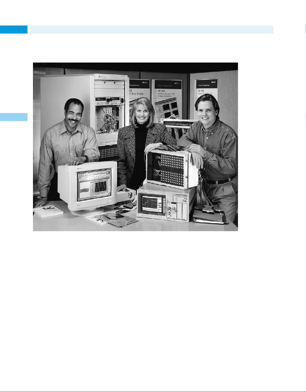
Product Support
72 System and Software Support Services
“Agilent really became a part of our team in developing
the solution.
2
They didn’t just sell us a box that we had to determine
how to implement on our own.”
Dan Finch,
C-Cor Electronics
Page 73
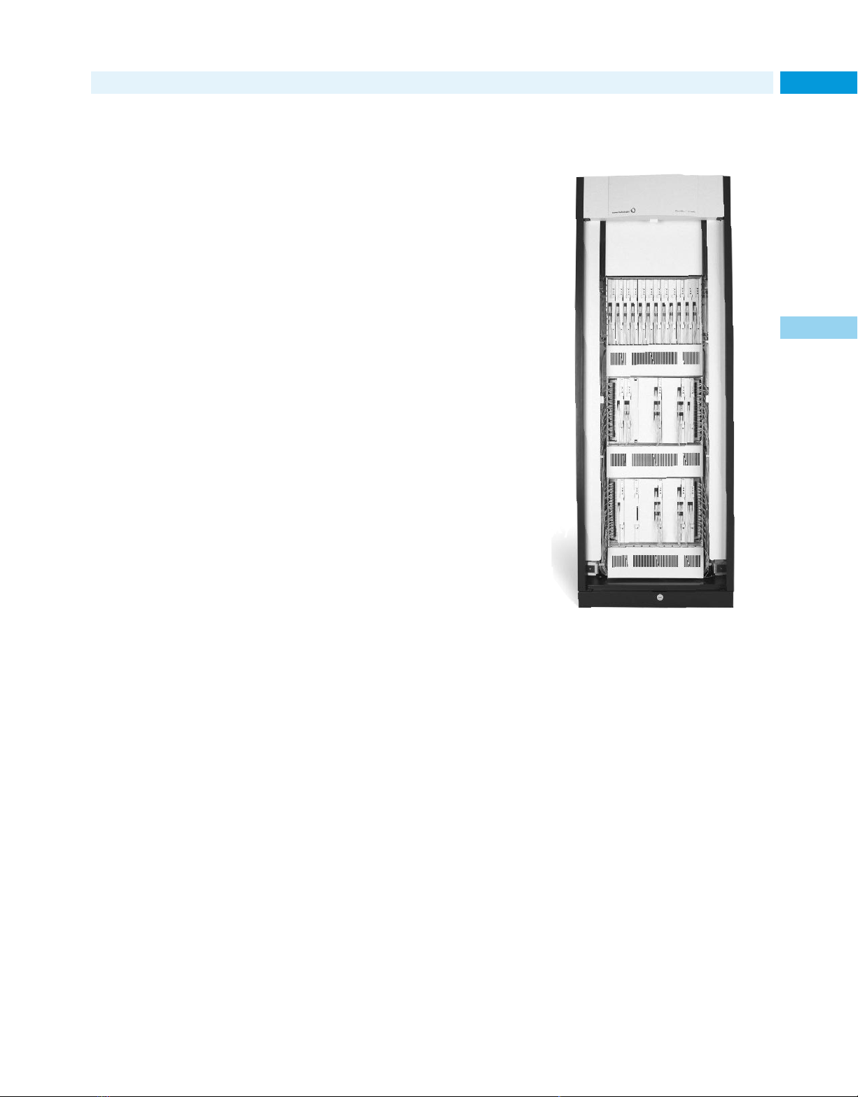
Success Story
Lucent Technologies helps networks feed bandwidth–
hungry applications and services
Fiber optics have given telecom and
datacom networks a huge capacity
boost in recent years. Unfortunately,
the Internet’s appetite has grown even
faster. In North America, for instance,
all that new fiber is already running at
70 to 80 percent of capacity.
Lucent WaveStar to the rescue
Network operators can respond in
two ways: add more fiber, and make
better use of the fiber they already
have in place. Lucent Technologies’
optical networking specialists are
leading the way in this second
effort, using a technology called
Dense Wave Division Multiplexing
(DWDM), that transmits multiple
wavelengths of light simultaneously.
Lucent has deployed more
than 2,400 DWDM systems already,
and its powerful new 80-wavelength
WaveStar
maximum capacity of 3.2 terabits of
voice, data and video per second.
™
OLS 400G boasts a
system test for Lucent Optical
Networking Group. “We chose
Agilent and were pleased that they
followed through well every time,
and sometimes came through even
sooner than expected.”
Agilent’s test system developers
and integrators worked in parallel
with Lucent’s development and test
teams, freeing Lucent to focus on
product development and meeting
all of its high standards for product
quality assurance.
“We optimize our processes to
address each customer’s needs,
allowing them to take as much ownership of test-solution design and construction as they like,” explains
David Kent, operations manager of
Agilent’s Test Solutions Operations.
“Lucent’s team collaborated very
closely with ours to draw up the system definition, and then we took
over to complete hardware and software design and construction rapidly.
It was an incredible team effort.”
Subheader
73Lucent Technologies
2
Teaming up to slice timeto-market
At the beginning of the product
development cycle, Lucent committed to delivering the new WaveStar
OLS 400G to its customers in under
a year, significantly less than typical
cycle times for a project of this magnitude. To help meet this ambitious
goal, Lucent needed quick development of a test system, too. Moreover,
Lucent’s engineers needed a way to
automatically test all 80 channels
efficiently and effectively.
“In selecting a vendor for this
test solution, we looked for a company that would really see us through
our tight schedule,” said Yassi
Moghaddam, technical manager of
The benefits of a common
test platform
A cornerstone of the rapid test
development strategy was a common
test platform that helped Lucent
leverage its convergent, crossdisciplinary efforts. As a result,
time invested in one area shortened
the cycles needed for other areas of
development. For example, automation scripts and test routines created
for the development stage were
refined and promptly implemented
during the system test phase.
Agilent’s test solution, based
on E1676B VXI OC-48c transceivers,
lets Lucent examine each bit in
a synchronous optical network
(SONET) signal. To save time, Lucent’s
Lucent Technologies WaveStar™ OLS
400G offers data rates up to 3.2
terabits per second to help ISPs and
other network operators meet skyrocketing demand for capacity.
engineers can perform each automated
test remotely. Plus, Agilent’s modular
system approach makes it easy to add
channels quickly, providing as much
scalability as Lucent’s development
cycle required.
As Lucent continues its leadership in the competitive optical networking market, the company can
continue to count on Agilent test systems to help deliver advanced networking solutions to those bandwidthhungry customers.
Internet URL www.agilent.com/find/tmc Product & Order Info See page 604
Page 74
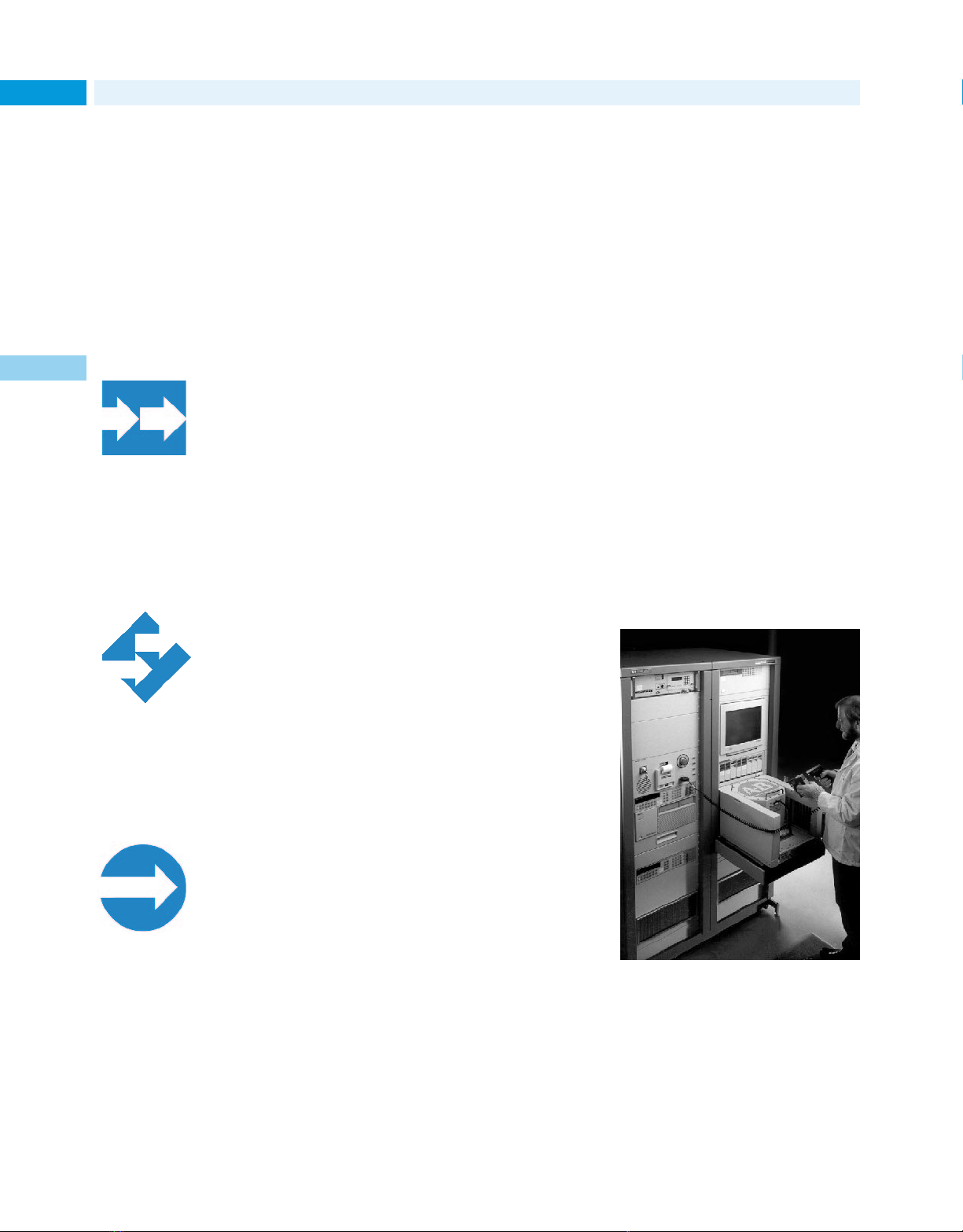
Electronic Test Systems
74 System Integration Services
Integration services designed to meet your unique needs
In the world of automated test, no
two projects and no two customers
are alike. That’s why every system
integration project from Agilent is
designed around your unique requirements and available resources:
Level 1: Build-to-print test
solutions
If your test engineers already have a
plan in place, we can build a system to
2
your design. We’ll procure and coordinate the
materials; then build,
deliver, integrate and
support the system.
Level 2: Collaborative test
solution services
We’ll work with your R&D, manufacturing, and field service teams to
design, specify, and support an electronic test solution. Sharing the design
and implementation
tasks is often the best
approach when product and test development need to progress
simultaneously.
Level 3: Turnkey test solution
services
At this level, we’ll cover the project
from start to finish; from business
needs analysis through field support
for the life of the system.
You get all the advantages of a professionally
designed system without pulling staff away
from other projects.
Choosing Agilent as your
development partner
Customers have used our integration
services for hundreds of systems
worldwide, enjoying significant business benefits:
• Getting products to market in
less time
• Making better use of people and
resources
• Cutting test costs
• Delivering better products through
more complete and better focused
testing
A complete range of services
and support
Our engineers and technicians are
experienced in every phase of custom system development:
• Business and technical analysis
• Specification
• Test system design
• Software design and development
• Materials procurement
• Integration
• Documentation
• Training
• Delivery, installation and inspec-
tion
• Specialized test fixtures
• Long-term support
• Performance analysis
• System relocation
Our areas of concentrated expertise
include wireless cell phone and infrastructure equipment, other
communications equipment, satellite communication systems and
aerospace/defense systems.
We can offer a unique combination of expertise that goes far beyond
system integration. As the world’s
largest test and measurement company and one of the largest manufacturing firms, we understand electronic test from the ground up.
Moreover, our global design,
support and delivery teams mean we
can support you wherever your business
takes you. After we’ve worked with
you to deliver a final solution, we can
quickly create multiple similar systems to deliver anywhere in the world.
Controlling test at
Allen-Bradley
When you manufacture more than 350,000
different products and product variations,
from power devices and sensors to programmable controllers and quality management systems, keeping a lid on test
costs can be a challenge. Moreover, AllenBradley wanted to streamline its test processes to simplify quality control, get new
products to market faster and even conserve valuable floor space. The ability to
test increasingly complex products was
another major concern.
To meet all these goals, Allen-Bradley
turned to Agilent’s custom test specialists.
The answer: a fully integrated solution
based on a scaleable, common test architecture adaptable at more than two dozen
sites worldwide. The results: a 10%
reduction in test development costs,
test execution times cut by as much
as 50%, and development cycle times
cut by as much as 12 weeks.
Page 75
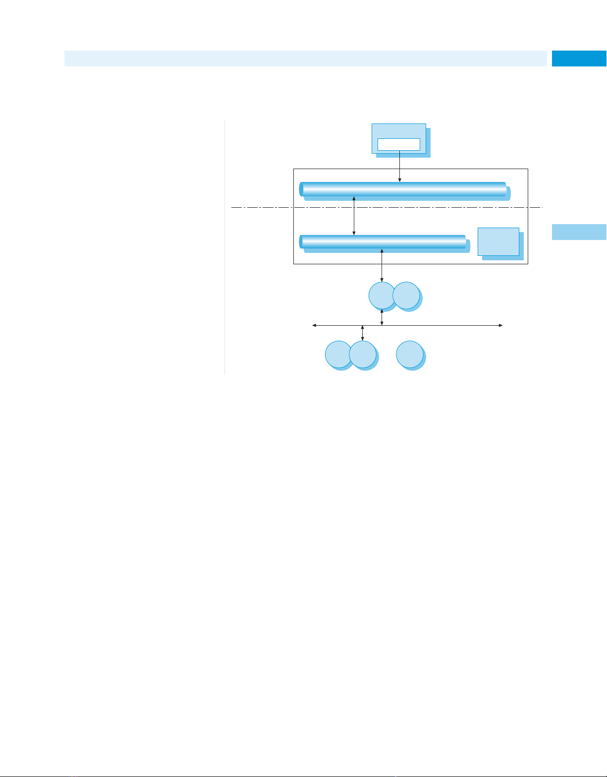
Synchronizing planning and production at
Henkel Waschmittel GmbH
Success Story
75Henkel Waschmittel GmbH
The ecologically-oriented Henkel
Group, a renowned specialist in
applied chemistry, is dedicated to
making people’s lives easier, safer
and more enjoyable. Pursuing these
goals, the company has achieved
leading positions in many areas of
chemical production, including the
European detergent and cosmetics
markets, the worldwide market for
metal surface treatment, and the
manufacturing of adhesive products.
Its Henkel Waschmittel GmbH division is a leading producer of detergents in liquid and powdered form.
Responding to changing
customer needs
In the early 1990s, the Henkel Group
deployed SAP R/3 as a standard
enterprise resource planning (ERP)
application throughout its operations. To increase its responsiveness
to customer requirements, the
Henkel Group wanted to take the
next step: plant-to-enterprise integration. Specific goals included synchronizing activities at the enterprise
level with the process control level,
achieving faster product delivery and
reducing inventories.
Linking processes across the
enterprise
To achieve this next level of integration,
Henkel Waschmittel called on Agilent
Consulting in Germany. The company
had several reasons for selecting
Agilent, starting with Agilent’s reputation for high quality products. Henkel
Waschmittel’s strong, decades-long
relationship with Agilent was also a
key factor. Plus, Agilent ’s size, stability
and worldwide presence met the needs
of their global operation.
Working with Agilent consultants, Henkel Waschmittel installed
Agilent Real Time Applications
SAP R/3
SAP PP-P1
Token Ring IEEE 802.5
Agilent Enterprise Line
Enterprise Integration
Process Integration
The custom Agilent systems installed at Henkel Waschmittel provide seamless data
integration throughout the organization.
Platform (RTAP), a process data
server that provides flexible, scalable
and dependable data management.
Henkel Waschmittel installed
four Agilent RTAP systems, with two
at the Düsseldorf-Holthausen site and
two at the Genthin site. At the ERP
level, Consulting recommended installation of Enterprise Link at Henkel
Düsseldorf-Holthausen. Enterprise
Messaging Middleware
Agilent RTAP
Process Data Server
Ethernet IEEE 802.3
Plug-in
PC
PLCs
• • •
tional data, failure reporting, production cycle times, and production
quantities. This ready access to production information has increased
the efficiency of decision making,
problem detection and control.
more efficient, thanks to the link
between planning and production
that Agilent RTAP provides.
Real-time
Applications
PLC
Simens
$5
SINEC Bus (H1, L2, ...)
Recipe management is also
Link is a certified messaging middleware that integrates SAP’s R/3 system with real-time control systems.
Agilent integrated these systems into Henkel’s existing IT environment, giving users easy access to
online data from the central server
via their Windows NT PCs. Production data of interest include temperature, viscosity, pH value, and the
product level in each storage tank.
The system can automatically generate reports for five major production
areas: process information, opera-
Leveraging the results
The team at Henkel Waschmittel
GmbH is very pleased with the
Agilent systems. Agilent Consulting
helped Henkel overcome the challenges of a complex implementation,
and results have exceeded expectations. Plans are already in place to
install similar systems at other
plants and to expand data correlation and fault detection features for
more in-depth analysis.
2
Internet URL www.agilent.com/find/tmc Product & Order Info See page 604
Page 76
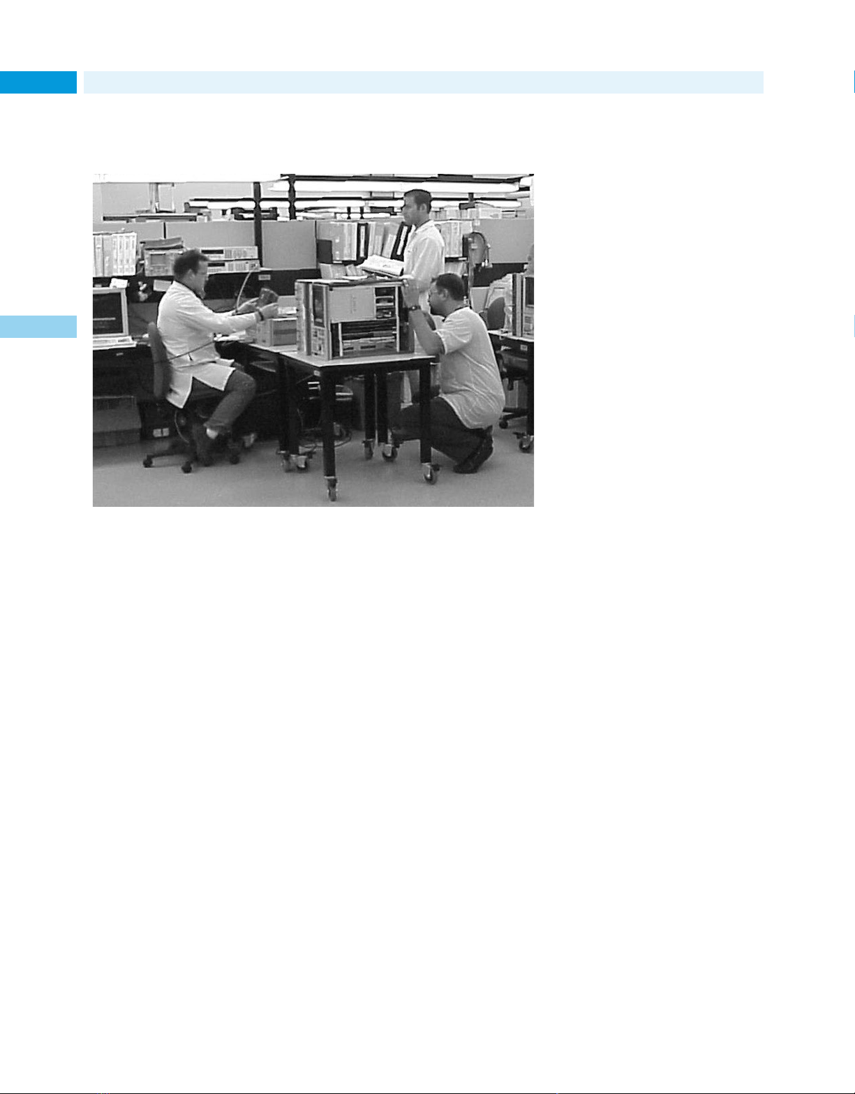
Consulting & Educational Services
76 Consulting
Knowledge is power: getting the right information
at the right time
result in both better operating efficiency and higher quality measurements,
thanks to our engineers’ in-depth
knowledge of Agilent equipment.
include just about any service your
staff would find beneficial:
• Setting up, installing and initializ-
2
• Training users or production line
• Interfacing instruments, systems
• Configuring data management
Productivity assistance is available
in flexible increments, so you can
buy as much or as little as you need,
scheduled at your convenience.
This productivity assistance can
ing new systems
operators
and workstations
or presentation options
From a few hours of productivity assistance to a specialized design project,
Agilent’s engineers can help you make the most of your Agilent equipment
while freeing your staff for key projects.
As a technical professional, you
understand that having the right
information at the right time can pay
for itself many times over. Our test
specialists stay on top of the latest
developments in technologies, test
techniques, measurement equipment
and regulatory details.
lowing page) is often the best answer.
However, if your needs are shortterm or highly specialized, it usually
makes better economic sense to
bring in a consultant while you focus
on your core business needs. Our
consulting services range from productivity assistance
to advanced application solutions.
Is consulting or training the
better choice for you?
If a measurement technique or other
required knowledge represents an
ongoing need, building the expertise
in your organization through one of
our many training courses (see the fol-
Productivity assistance
Having an experienced user by your
side can be a great help when you
need to get up to speed quickly with
your new Agilent equipment. A few
hours of productivity assistance can
Application assistance
Our engineers are also available for
more in-depth application support,
from specialized measurements and
troubleshooting to test process
reviews and system optimization.
Here are just a few of the application
areas in which they’ve helped clients
with unique test challenges:
• Phase noise measurements
• RF and microwave component
design and testing
• Digital systems design and debug-
ging
• Data acquisition and dynamic sig-
nal analysis
• Communication systems testing
and troubleshooting
• Establishing measurement
processes and procedures
Page 77

Consulting and Educational Services
Take advantage of the latest test and measurement techniques
77Training and Education
Agilent’s industry and technology
specific training services are a cost
effective way to develop measurement expertise, from fundamental
principles to the newest techniques
in digital debugging or high-frequency design.
Training based on your
specialized requirements
As with all of our professional services, Agilent training courses can be
adapted to fit your specific needs:
• In addition to classroom training,
some of our most popular courses
are available in self-paced, computer-based formats
• On-site delivery is available for
nearly all instructor-led courses
• Custom training courses can be
developed for specialized needs
Learn more in less time
Agilent training courses employ both
the latest in training technology and
proven techniques for professional
education:
• Our instructors understand your
industry and speak your language;
they know how to make the
measurements you need to make
• Product and industry specialists,
curriculum engineers, writers
and instructors develop course
materials as a team to ensure
effective knowledge transfer
• Class sizes are limited, often
ranging from 6-10 students
• Most courses include extensive
hands-on experience
• Instruction includes the physics
behind the measurements to help
students apply their knowledge
on the job
Variety of courses
Training courses cover a wide range
of test and measurement applications and industries:
• Automated testing using VEE
• Electromagnetic compatibility
• RF, analog and digital signal analy-
sis and monitoring
• RF component and materials testing
• High-frequency design systems
• Datacom, telecom and mobile
communications
• Board test systems
• Digital design and debugging,
including embedded control systems
• Mixed signal, memory and
processor testing
Course descriptions and schedules
for each region of the world are available by calling Agilent or by visiting
our training web site at:
www.agilent.com/find/tmeducation
Building competitive
advantage with an
informed work force
2
Agilent’s experienced instructors use the latest technologies and training
approaches to maximize educational effectiveness.
A large wireless maufacturer in Singapore
recently faced one of the biggest challenges a rapidly growing company can
encounter: developing a trained work force
fast enough to keep up with soaring
demand.
The company turned to Agilent for
help. Our wireless experts analyzed their
immediate and long-term needs, then
developed a custom curriculum around
the needs of technicians, engineers and
equipment operators. Ten on-site classes
were established, with over 100 employees passing certification examinations.
Ongoing curriculum enhancements help
the staff stay up to speed on emerging
technical developments.
Internet URL www.agilent.com/find/tmc Product & Order Info See page 604
Page 78

Success Story
78 Microelectronics Technology, Inc.
Support makes the difference in the fast-moving
telecommunications market
From its base in the “Silicon Valley of
Taiwan,” Microelectronics Technology,
Inc. (MTI) has gained an international
reputation as a supplier of communications components. Major manufacturers in the U.S. and Europe rely on
MTI components for personal communication systems and other popular
technology-driven products.
2
Responding to competition by
getting closer to customers
To respond to the high level of competition in these markets, MTI is working hard to foster close relationships
with all its customers. According to
Jason Chang, MTI’s Vice President of
R&D, “Microwave communications
technology is rapidly developing and
the market is becoming more and
more competitive. As a result, equipment suppliers and manufacturers
have needed to establish better and
closer relationships.”
To keep up with the the rapidly
changing and complex technologies
in the communications market, and to
shorten product development cycles,
MTI needed to make sure its R&D
department was equipped with leading-edge design, development and
test solutions.
Prior to working with Agilent, MTI
had been negotiating a purchase
arrangement with another equipment
supplier. As Mr. Chang explains,
though, “We had an opportunity to
meet with the Agilent people to talk
about their new IQG signal test system. Based on that discussion, we
suspended the other purchase order
and evaluated the Agilent solution.
The evaluation indicated the Agilent
was a better match with MTI’s current needs in terms of pricing, performance, flexibility and support.”
Supporting customers in fastpaced markets
William Wang, Director of MTI’s
Special Electronics Department,
believes the key factor affecting the
decision was after-sales service and
technical support. To cope with the
fast pace of development in the
microwave communication market,
strong support is crucial during
research and development.
Agilent’s test specialists in Taiwan
wrote the software for the new system, so any problem that might arise
could be solved by the programmers
directly and efficiently.
The nature of Agilent’s support team
in Taiwan was an important factor
as well. Unlike some companies that
deliver support through a single
technician, Agilent Taiwan supports
clients with an integrated team of
more than 30 engineers.
The cooperation between MTI and
Agilent over the years has established a mutual understanding that
minimizes problems and quickly
resolves those that do arise. MTI
is looking forward to a continued
partnership as the integration of
the telecom, electronic media and
computer businesses provides continued development opportunities
and challenges.
Cutting test development time
with reprogrammable systems
In the past, MTI created hardware setup methods for its test procedures, in
which each test setup could perform
tests on only one particular component. Once the standard or component was changed, all the procedures
had to be redone. The result was
inevitable delays, delays that became
unacceptable as customers demanded
faster and faster turnaround times on
new designs.
MTI needed a more flexible test system in R&D, along with a partner who
could be relied upon to deliver and
support such a system locally.
From left to right: William W.S. Wang, MTI Director of Special Products;
Jason L.C. Chang, MTI Vice President of R&D; Tony Chen, Agilent Consultant;
and Lobo Wong, Agilent Senior Account Manager; stand before display of
MTI communications products tested by Agilent test system.
Page 79
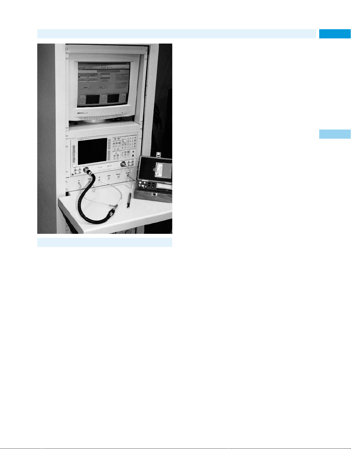
Channel Partners
Partnering for Success
Partnering for Success
Agilent Technologies and its industry-leading Channel Partners are
committed to delivering integrated test solutions to help you reduce
your time-to-market and increase your engineering productivity.
These test solutions include high-performance measurement platforms, software applications, and support.
Custom Solution Integration Partners
To complement our test system design and implementation services, Agilent has formed relationships with other test systems
integrators as part of our Custom Solution Integration Partner
Program. Together with these general integration partners, we can
offer test systems solutions in a broad spectrum of applications.
Complementary Solution Providers
There are some applications where Agilent resources and products
are only a part of the total solution. Often, these applications require
additional capabilities offered by our Complementary Solution
Providers. These companies bring quality applications, solutions
expertise, and industry knowledge to the solution equation.
Together, we deliver industry-focused solutions in the following
application areas are just some examples:
• Antenna test
• Battery/Power supply test
• Calibration
• Data acquisition
• Electrical system component test
• Electronic/Electrical test
• Electronic component test
• Electronic functional test
• Electronic sub-assembly test
• High speed digital test
• Jet/Turbine engine test
• Microwave semiconductor test
• Mechanical functional test
• Noise, vibration, and harshness
• Piston engine test
• RF/MW device characterization
• Rotating machinery analysis
79
2
Proven Solutions for Global Competitiveness
Agilent Technologies Test and Measurement instruments, as well
as systems and related services, are used by engineers and scientists around the world to design, manufacture, operate, and repair
advanced electronic equipment. Whether you’re developing products, analyzing signals, or measuring product performance, you
can rely on Agilent quality and reliability for accurate results.
These results include a variety of product and process parameters—
critical data that yields the information you need for smart engineering decisions.
For more information about these solutions, visit our Channel
Partner Solutions Portfolio web site: www.agilent.com/find/tmpartners
Internet URL www.agilent.com/find/tmc Product & Order Info See page 604
Page 80

You’ve read the book, now see the Web site.
www.agilent.com/find/tmc
Test & Measurement
catalog
2001
The industry’s most prestigious online test and
measurement resource is at your fingertips: The
Agilent Technologies website. All the information
you need to research, locate and purchase the test
equipment you want.
Including:
Extensive product/application information:
• Datasheets
• Manuals
• Application notes
• Tutorials
• FAQ’s
• Interactive demonstrations
• Comparative product data and evaluation tools
• Free software
Keep yourself up-to-date:
• News about special promotions, events, and
T&M education courses
• A technical forum
• Obsolete product replacement recommendations
• Alternative purchasing plans
Now faster and easier than ever:
• Access to customer support services
• Information in your local language*
• Prices in your local currency*
• Agilent product order status reports
It’s the only web site that can live up to the catalog –
and your needs. Bookmark it today and visit often!
Footnotes:
*Availability of this feature may be limited; an expansion program is ongoing.
For best results, view the Agilent website with Microsoft’s Internet Explorer
browser.
www.agilent.com/find/tmc
Page 81
Design & Test 3
Software and Systems
Instrument to Network
Connectivity Initiative 82
Communications EDA Software 84
Test Software 86
MMS Products 90
See also
Consulting Services 76
VXIbus Products 93
See also
Test Software 86
System Switches 97
Data Acquisition Systems 530
Consulting Services 76
System Switches 97
See also
VXIbus Products 93
81
Interface Products 101
Additional Literature 103
Page 82
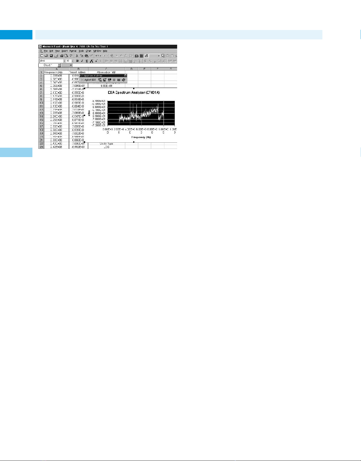
Design & Test Software and Systems
Instrument to Network Connectivity Initiative
82 51.1
Connectivity
Software
3
Microsoft Excel spreadsheet, with data imported from an Agilent ESA spectrum
analyzer, showing the add-in tool bar feature and a waveform screen capture
from the instrument.
Connecting PCs to Instruments
Agilent offers a set of connectivity tools that enable you to quickly
and easily move data from your Agilent instruments to your PC.
Whether you are an experienced programmer or would prefer not to
program at all, our connectivity solution is designed to give you a
high-level of instrument control using software applications that
you are probably already using on your PC.
A Simple Toolbar Add-in for Excel and Word
Agilent’s solution provides an easy-to-use toolbar that enables you
to save instrument settings to file and retrieve them for later use,
insert instrument readings into Microsoft Excel or Microsoft Word,
and log instrument readings in Excel. Once installed, the toolbar is
automatically loaded and operates just like any other tool bar in
these applications.
Connectivity Strategy
The connectivity technologies developed by Agilent provide you with
a significant competitive advantage. Agilent is committed to the
value added by built-in connectivity capabilities included with our
test and measurement equipment such that we have dedicated fulltime resources chartered with the following activities:
• Exploit the macro-trend toward computer-based instruments
by enabling more instrument/measurement functionality in
software while reducing complexity and cost of hardware. By
reducing the complexity of the hardware, and programming more
features and functions into the software, Agilent is making it
easier to use our test and measurement equipment.
• Create value and differentiation by making it faster and easier
to create measurements and test by focusing on ease-of-use, easeof-learning by using familiar environments and paradigms. You
want to be able to use your equipment in familiar environments
such as web browsers, Microsoft applications, MATLAB, Visual
Studio, and Agilent VEE.
• Use a software component strategy and a suite of new services to
deliver on the vision. Component technology is a key enabler for
providing customer value and improves internal efficiencies.
• Capitalize on key Agilent competencies by providing ways to
create, encapsulate, and deliver “measurement science” and
“test technology” in software and services.
• Provide unique and compelling value by easing the migration of
measurements across the lifecycle of our customer’s products.
Working with you, our partner, we provide solutions for today while
developing the next generation of technologies, tools, and methods.
Built-in Software Features
With our connectivity test and measurement solutions you can
move instrument data to your PC-based applications such as MS
Office, visualize, analyze, and print your test and measurement
results. And, if you are developing test programs for automated test
systems, Agilent’s connectivity products work seamlessly with your
standards-based development environment, ensuring the fastest
time to test.
Agilent Technologies instruments work effortlessly and seamlessly with the use of an integrated toolbar—access to your instrument’s data and graphics is only a few mouse-clicks away. We
provide a faster and easier way to create reports and analyze measurement results by focusing on ease-of-use and ease-of-learning
while using familiar environments such as:
• Toolbars in MS Office provide direct access to instrument data,
screen shots and instrument setups.
• Active X controls and COM driver objects
• On-line Help
Programming Examples or little programming of instrumentation
• Minimal test automation needs
• Accurate, full-featured instruments
• Interactive environment for experimentation
• Analysis and visualization tools to aid in interpretation of
measurement results
• Better understand and manage the transition of a design from
the “virtual” world to the “real” world
• Maintenance of a lab notebook, report generation, design
documentation
Linking Your Equipment
Agilent Technologies believes you should be able to access and monitor your instruments at anytime and at anyplace. Agilent accomplishes this by basing its I/0 strategy on established computer I/0
standards, such as Ethernet and IEEE 1394 while supporting legacy
test and measurement standards such as IEEE 488.
As an R&D Engineer, you need to easily get data from your
instruments into your PC applications (e.g., Excel, Word, and technical analysis applications) without programming.
You will be able to use the same I/O connector and cable to
connect your instrument to your PC as you do for your other PC
peripherals.
• On the desktop (Serial)
• Within a system (GPIB)
• Throughout the enterprise (LAN)
Easily connect to your instrument from your favorite choice of
programming environments.
• Measurement Specific (i.e., Agilent VEE)
• General Purpose (i.e., Microsoft Visual Studio)
Integrated with Your Programming Environment
Agilent Technologies helps you accelerate your measurement insight
in design verification, manufacturing test, process control, and data
acquisition by providing software tools in the environment of choice
using the familiar programming for each task and accelerating flexible deployment.
Page 83
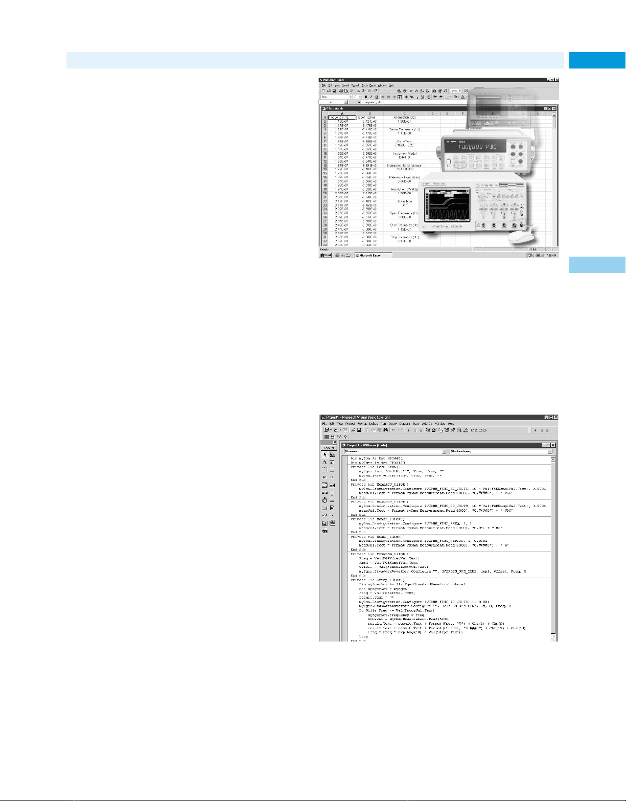
Design & Test Software and Systems
83Instrument to Network Connectivity Initiative (cont.)
Minimum System Requirements
PC Operating System Requirements:
Windows 95 or Windows 98
Windows NT 4.0 SP 4 or higher, Windows 2000
Pentium-90
32 MB RAM
20 MB free disk space
Environments Supported
Applications:
Microsoft Excel 97, Excel 2000
Microsoft Word 97, Word 2000
Software Development
Visual Basic 5.0/6.0
VBA 5.0/6.0
Agilent VEE 5.0 or greater
Visual C/C++ 5.0/6.0
Driver Standards
IVI, or Interchangeable Virtual Instruments, is a new instrument driver standard based on the COM (Component Object Model) computer standard. The IVI Foundation, an open consortium of companies
chartered with defining software standards for instrument interchangeability, is developing IVI Open Architecture, which will give
you the ability to use IVI drivers in the development environment of
your choice. By defining a standard instrument driver model that
enables you to swap instruments with reduced software changes,
the IVI Foundation members believe that significant savings in time
and money will result:
• Test software on long-life test systems can more easily be updated
when instruments become obsolete.
• A single test software system can be deployed on test systems
with different instrument hardware to maximize use of existing
resources.
• Test code developed in R&D labs can be ported to different
instruments in the production environment. In situations
where drivers alone cannot provide the required level of interchangeability, IVI-MSS components can provide more robust
interchangeability.
3 Types of IVI Standards:
• IVI-Open Architecture—The foundation needed to create driver.
• Classes—define the category: API (Application Programming
Interface) for type of instrument.
• IVI-MSS Solution—In situations where drivers alone cannot
provide the required level of interchangeability, IVI-MSS
components can provide more robust interchangeability.
• Critical production test systems can remain online when
instruments malfunction or need recalibrating.
Once loaded, the IVI instrument drivers can be used to access
“home base” applications, which include Visual Basic, Visual C++,
Microsoft Office, Agilent’s VEE, and MathWorks MATLAB as well
as browsers.
For more information, visit our web site at: www.agilent.com/find/gp
Connectivity
Software
3
Internet URL www.agilent.com/find/tmc Product & Order Info See page 604
Page 84

Communications EDA Software
Advanced Design System
84
Advanced Design System—A Unified Environment
for Communication Signal Path Design
3
The challenge of communications design is to shorten time to market, while making better, smaller, faster products. Agilent EEsof
EDA’s Advanced Design System simulates the entire communications signal path for today’s and tomorrow’s next generation communications product design. This unique solution integrates proven
RF, DSP, and electromagnetic simulators into a single, flexible
design environment.
Combining Proven Technology with New Innovation
Advanced Design System provides new DSP design and synthesis
technologies and significant new design capabilities for RF, microwave, and RFIC, all integrated into one efficient, flexible design
solution. The integration of RF and DSP analysis engines allows realtime co-simulation and is unique in the EDA industry. The integration of multi-discipline design tools into a single environment and
database eliminates the barriers caused by separate processes and
allows design teams to easily examine tradeoffs and optimize design
margins. This design environment is available for both PC and UNIX
platforms. The PC version can be run on a modern laptop, creating a
more flexible design environment.
Bridging the Gap Between Simulation Technology
and Applications
To answer the many challenges that communication design engineers face today, Agilent EEsof EDA offers a significant new direction and approach for the communications EDA industry. Agilent
EEsof EDA now bridges the gap between simulation technology—
software simulation tools and real-world design—your applications.
Breakthroughs in simulation technology and rapid expansion of
new products like DesignGuides, synthesis tools, Design Libraries
in Advanced Design System, and application-oriented education
significantly reduces design time, increases productivity and efficiency, and ultimately gives designers an edge over the competition.
System Design
The Advanced Design System top-level design solution, Communication Systems Designer, offers unprecedented speed and accuracy
in mixed DSP/RF system simulation.
Communication System Designer’s RF system simulation capability is enhanced with an extremely fast harmonic balance simulator that allows engineers to compute full budget simulations on any
RF topology. Included are measurements for dozens of system-level
parameters such as incident power, noise figure, third-order products, signal-to-noise ratio (SNR), noise bandwidth, and more. RF
system simulation analysis of control circuits such as phase-locked
loops and automatic gain control loops allows engineers new freedom to experiment with innovative approaches to their designs. An
instrument server lets users link to RF and communication measurement instrumentation.
For DSP design, Communication System Designer has a new
signal-processing engine that allows processing of data in vector and
matrix form. Included are over 300 DSP models, Bit Error Rate
(BER) testers that have both Monte Carlo prediction and a faster
variance reduction algorithm, and advanced post-processing such
as FFT, correlation, cumulative distribution function (CDF), probability distribution function (PDF), and complex math functions. The
optional link to MATLAB has a user-friendly C-code interface.
Communication System Designer also offers optional Design
Libraries for wireless standards such as EDGE, cdma2000, W-CDMA/
3GPP, GSM, and CDMA.
RFIC Design
Circuit simulation technology in Advanced Design System features
dramatic enhancements resulting from patented new technologies.
RFIC Designer offers integrated RFIC simulation technologies that
provide the most efficient and accurate verification of RFIC performance against modern digital wireless standards specifications,
such as adjacent channel power ratio (ACPR) and error vector magnitude (EVM) of CDMA systems.
Co-simulation of RF and DSP interactions in RFIC chipsets
ensures on-spec performance without costly iterations.
Agilent EEsof EDA provides services to integrate Advanced
Design System into design flows that use Cadence and Mentor
Graphics products.
DSP Design and Synthesis
Digital Signal Processing is a vital part of today’s communications
designs. Advanced Design System addresses this need with the
inclusion of two new DSP tools: DSP Designer and DSP Synthesis.
These two products were developed especially to help DSP design
engineers create and evaluate baseband designs.
The Agilent Ptolemy simulation engine facilitates co-simulation
of time, frequency, and data-flow technologies and significantly
expands the DSP development capability for mixed RF/analog/DSP
communications projects. Agilent EEsof EDA is the only EDA vendor
to deliver RF/DSP co-simulation capability within a complete design
environment.
DSP Synthesis offers powerful capabilities to help both DSP and
IC designers move quickly from a system-level design to implementation, which improves productivity and reduces development cost.
Page 85
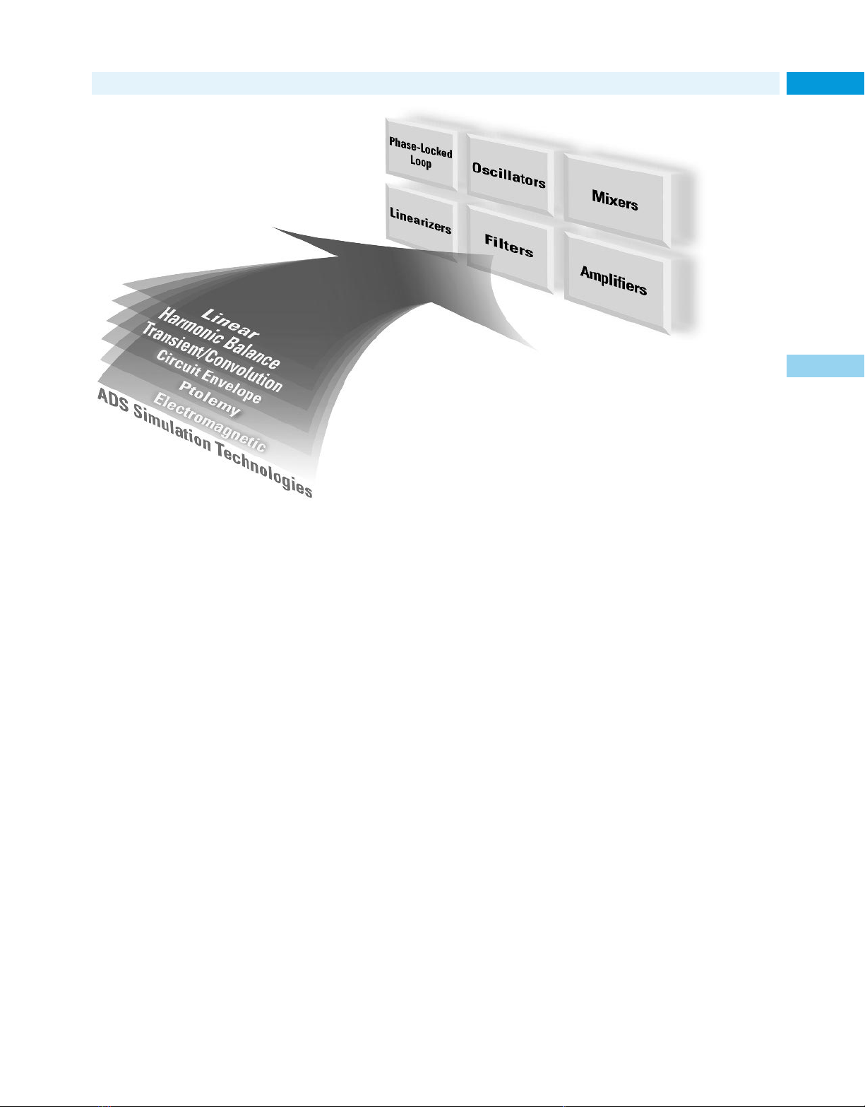
Communications EDA Software
Advanced Design System
85
E8900
85180A
85122A
3
DesignGuides apply the breadth of Advanced Design System simulation technologies to a wide variety of applications.
Microwave Circuit Design
For traditional design, the microwave circuit designer benefits from
the integration of system, circuit, and electromagnetic simulation,
as well as full schematic and layout, microwave hybrid, and MMIC
design tools. Microwave Circuit Designer includes a Design Rule
Checker with an easy-to-use, rules-writing interface. A Graphic Cell
Compiler allows the designer to create footprints graphically without programming and to compile them into AEL (Application
Extension Language) macro language, providing layout enhancements for ground-plane management and better trace handling.
Planar and 3D EM Design
Electromagnetic design and simulation tools are an integral part of
the RF and microwave design process.
Agilent HFSS Designer provides accurate EM modeling of arbitrarily shaped passive 3D structures. Agilent Momentum is a planar
EM simulator that allows RF and microwave designers to significantly expand the range and accuracy of their passive circuits.
Optimization technology provides design as well as analysis capabilities for both planar and 3D structures.
RF Board Design
Whether a cellular/PCS phone, pager, or next generation wireless
product, today’s communications products ultimately are built
using PCB technology. RF Board Designer provides design, simulation, and analysis capabilities for a complete top-down design from
system to circuit and physical design, all within a single integrated
environment.
Device Modeling Systems
Agilent EEsof EDA Device Modeling Systems are the first total systems specifically dedicated to active device modeling. They combine
parameter extraction and test hardware with IC-CAP modeling software. Industry-standard SPICE models as well as Agilent EEsof
EDA high-frequency models are available for FET, HEMT, BJT, MOS,
diode, and thin-film devices.
The IC-CAP software provides the total framework environment in which standard, modified, or fully custom device models
may be extracted or generated. Specific models include Agilent Root
FET and MOS Model Generators, as well as FET, BJT, HEMT, diode,
and thin-film models.
Key Literature
Advanced Design System Brochure, p/n 5966-2870E
What’s New in Advanced Design System 1. 3, p/n 5968-8754E
RF Board Designer Brochure, p/n 5966-2872E
RFIC Designer Brochure, p/n 5966-2871E
Microwave Circuit Designer, p/n 5966-0671E
High-Frequency Structure Simulator Brochure, p/n 5967-5846E
Communication Systems Designer Brochure, p/n 5966-0670E
DSP Designer Brochure, p/n 5966-2869E
DesignGuides Folder, p/n 5968-8157E
Device Modeling Systems, p/n 5968-6082E
Support
A complete line of support products includes software updates and
telephone technical support. Please contact the Agilent Test &
Measurement Call Center in your region for more details.
Libraries
Part of Advanced Design System’s power lies in its extensive
libraries. Advanced Design System provides over 100,000 models for
popular devices from numerous vendors. Design Libraries for
W-CDMA, EDGE, GSM, and 3GPP standards provide pre-built behavioral models, simulation systems, and test benches that speed up
new product development.
Ordering Information
E8900 Advanced Design System, Agilent 85180A High-Frequency
Structure Simulator, and the 85122A Precision Modeling System
come in a number of configurations and bundles.
For more information, please call the Agilent Test & Measurement Call
Center at 1-800-452-4844 (in North America), or refer to our web site:
www.agilent.com/eesof-eda
Internet URL www.agilent.com/find/tmc Product & Order Info See page 604
Page 86
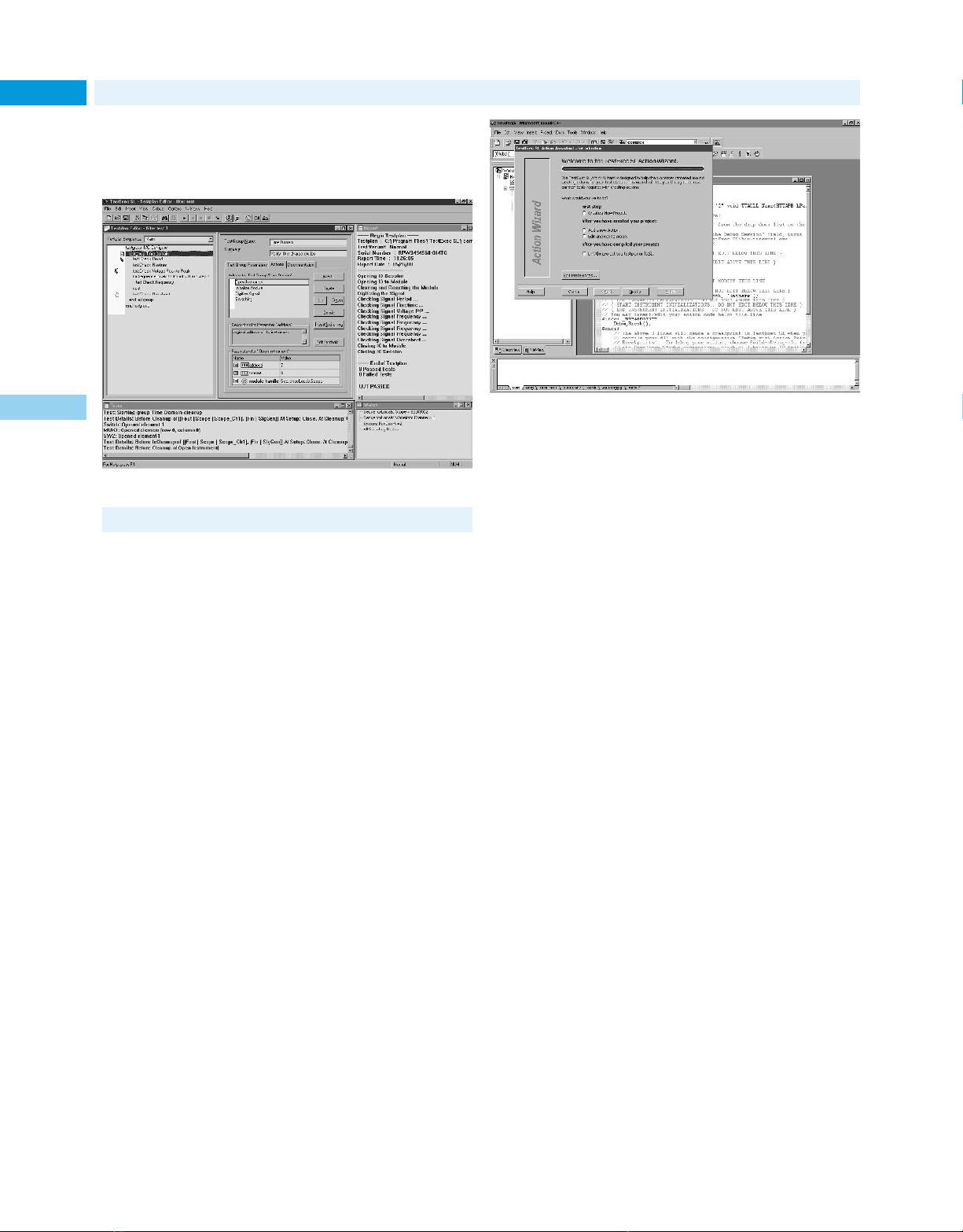
Test Software
86 Test Executive Software Platform
• For manufacturing functional test
• Version 4.1 for standalone applications
• Configuration tools for rapid system integration
• Available on Windows NT and Windows 2000
• Agilent Intelligent Test compatible
3
Test Exec SL Testplan Editor
TestExec SL 13
TestExec SL is a fully featured test executive platform that offers both
a robust system development environment and a simple-to-use but
fast execution engine. TestExec SL speeds time to market based on
rapid test plan development and integration with a software framework for re-use. It also helps improve production capacity with tools
that profile test execution and enable multiple-UUT testing.
Rapid Test Plan Development
TestExec SL features a complete software framework for developing
and debugging even the most complex test plans.
• Test plans use a structured hierarchy for logical grouping and
association of test groups, tests, and actions.
• Test sequencing supports conditional flow control.
• Tests and actions can be developed in language of choice
(C++, VEE, LabVIEW, etc).
• Action wizard utility generates DLL-style C code to integrate
user-defined actions.
• Debug environment includes breakpoint settings and watch and
trace windows.
• Framework for software reuse includes facilities for managing
action libraries.
• Test plan compatible with all earlier embedded versions of
TestExec SL.
Usability Tools for High Performance
TestExec SL has many valuable time-saving integration tools that
help test engineers take some of the pain out of system integration.
• Throughput multiplier enables hardware-sharing multiple-UUT
testing without the need for custom software.
• Switch manager helps manage the complex topologies between
instrument and UUT.
• Configurable data logging exports data in CSV ASCII, XML and
Agilent 3070 formats.
• Test profiler compiles and displays key test performance results
for optimal system tuning.
• Run-time user interface customization supports Visual Basic and
ActiveX.
Test Exec SL Action Wizard plug-in for Microsoft Visual Studio
Test Development Environments Supported
Microsoft Visual Studio (C, C++, and Visual Basic)
Agilent VEE Pro
BASIC for Windows
National Instruments LabVIEW
National Instruments LabWindows/CVI
Compatible Instrument Drivers
C/C++ DLL-style or COM instrument drivers
VXIplug&play devices
Message-based instruments including IEEE 488.2 instruments
Drivers included with VEE, LabVIEW, or LabWindows/CVI
Minimum System Requirements
300 MHz Pentium-class PC
64 MB available RAM
35 MB disk storage minimum
Microsoft Windows NT 4.0 or Windows 2000
Evaluation Copy
The easiest way to appreciate the extensive capabilities of TestExec
SL is to try it. The evaluation copy lets you explore the entire product and includes a comprehensive walkthrough tutorial. To download an evaluation copy of version 4.1 of TestExec SL or to request it
on CD-ROM (p/n 5980-1487E), visit our web site at: www.agilent.com/
find/testexec
Worldwide Support
With TestExec SL, you have access to Agilent’s worldwide resources for
startup assistance, phone support, training, consulting, and update
services. Telephone technical support is offered worldwide 24/7
through our 4 regional response centers with 4 hour response time.
Key Literature
TestExec SL Product Data Sheet, p/n 5980-1240E or visit our web site at
www.agilent.com/find/testexec
Ordering Information
E2011E TestExec SL Version 4.1 4
Opt US1 Development License
Opt R0L Run-Time only license
Opt AGE Upgrade from version 3.2 or earlier
Opt H00 Annual Site support contract
Opt P00 Add caller to support contract
Opt 24C TestExec SL Intro Training (2 days)
Opt 24D TestExec SL Developer Training (3 days)
4 Indicates QuickShip availability
Page 87
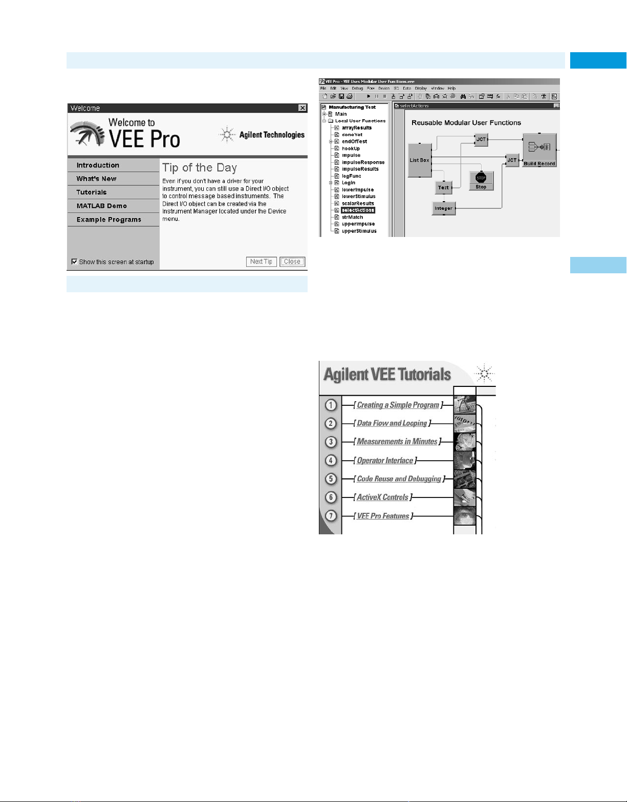
Test Software
87Agilent VEE Graphical Programming Environment
• The easy graphical programming environment
• Fast measurement analysis results
VEE Pro and VEE OneLab 3
Measurements to Minds
Agilent Technologies is in the business of connecting measurements
to minds to market. The Agilent VEE software family builds upon
the popularity of HP VEE 5.0 with its industry-standard approach to
math analysis, visualization, and signal processing. It integrates two
separate software packages into a single graphical environment that
handles both measurements/data collecting and spreadsheet/math
analysis. You actually get the built-in power of MATLAB Script and
the Signal Processing Toolkit from The MathWorks. These capabilities are embedded within VEE at no extra charge. With VEE 6.0,
tests are developed faster, results are analyzed more easily, understanding is increased, and data analysis is greatly enhanced. VEE
makes it possible within your familiar “home base” environment,
leveraging the solutions you have in place today.
VEE Is Efficient
VEE’s is self-documenting: it illustrates the connections between
individual objects and the wires that join them to create a program.
Where appropriate, many objects (such as MATLAB objects) also
include powerful textual code within the object itself. Objects include graphs, displays, advanced math, signal processing, and more.
The objects can be built into reusable, modular UserFunctions (or
UFs), making it easy to configure and reconfigure programs. Events
between objects can be managed by special sequencing wires or
objects. Since execution of code is determined by dataflow through
wires, VEE can multitask by running multiple execution threads
and UFs in parallel.
E2120G
E2111G
E2117G
E2119G
E2123G
H2327G
H2328G
82345G
82351G
82353G
3
VEE Is Graphical
VEE is an award-winning, uniquely productive, two-dimensional
programming environment. To create a program, you choose highlevel graphical objects from the menu and connect them with wires
(no more low-level icons to represent each textual line of code). The
wire connections help specify functionality and sequence in intuitive block diagrams. You program at a higher, task-oriented level
using built-in scientific and engineering routines. VEE jumpstarts
your programming effort, and maximizes the 2-D programming
space for faster measurement analysis results.
VEE Is Highly Usable
• Includes seven multimedia built-in tutorials (for Windows).
• Converts automatically among 16 data types without extra
programming.
• Opens welcome windows automatically for the VEE example
directory and MATLAB demos.
• Provides context-sensitive tips and help.
Internet URL www.agilent.com/find/tmc Product & Order Info See page 604
Page 88
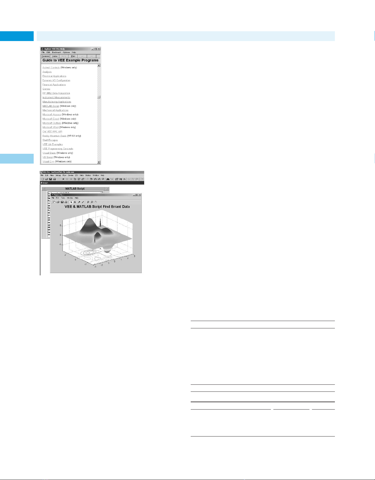
Test Software
88 Agilent VEE Graphical Programming Environment (cont.)
E2120G
E2111G
E2117G
E2119G
E2123G
H2327G
H2328G
82345G
82351G
82353G
VEE is Multi-Language
Environment
As an open graphical environment,
VEE works with leading products
across all market segments. It accepts
data from any vendor’s instrument
or PC card. It supports leading applications such as Microsoft Excel
and Word, The MathWorks MATLAB,
Microsoft Internet Explorer, and
Netscape Navigator. It supports popular programming languages including
Visual Basic, C, and Visual C++. It
works with manufacturing equipment via ActiveX, including surfacemount machines and robots. Agilent
VEE can be used as a standalone
solution or it can deliver measurement analysis results from custom inhouse solutions. It becomes part of
3
your environment without changing
the way you do business.
VEE Is Measurement Smart
• Program the properties of your instruments quickly, easily,
graphically.
• Take any measurement and control any PC card or instrument
from any vendor.
• Use over 500 National Instruments LabWindows/CVI drivers.
• Create runtime executables easily with embedded I/O configuration, and distribute the programs, at no extra charge.
• Verify instrument addresses and other parameters automatically
at runtime.
• Troubleshoot instrument timeouts and other errors automatically.
VEE Expanded Family: VEE Pro and VEE OneLab
With the introduction of the Agilent VEE 6.0 family, a new member is
added—VEE OneLab 6.0. VEE OneLab creates an unprecedented industry price/performance point for individual engineers and scientists programming measurement solutions. VEE Pro 6.0 is designed for large
projects using complex measurements and includes web enablement,
ability to create unlimited RunTime versions, interprocess communication, and advanced debugging and documentation tools.
Minimum System Requirements
• PC with a Pentium 120 MHz processor; 266 MHz Pentium II or
higher recommended
• Microsoft Windows 95, Windows 98, Windows NT 4.0, or
Windows 2000 operating system
• 24 MB RAM with Windows 95/98, 48 MB RAM with Windows NT/
Windows 2000
• Hard disk free space: 25 MB minimum (without MATLAB); 60 MB
with MATLAB and tutorials
• CD-ROM drive
Embedded MATLAB Script Yields Built-In Analysis
The power of MATLAB Script and the Signal Processing Toolkit
embedded within VEE, (from The Mathworks) delivers unprecedented analysis and visualization capabilities in a single graphical
environment. You get hundreds of functions with VEE, plus the 500
most popular MATLAB functions preprogrammed as one-click VEE
objects, including:
• Numeric and symbolic computation, including linear algebra and
matrix computation, Fourier and statistical analysis, differential
equation solving, matrix manipulation, trigonometric and other
math operations.
• Data analysis, manipulation and reduction.
• Volume visualization of scalars and vectors, multiple lighting
sources, camera-based viewing.
• Engineering and scientific graphics: 2-D and 3-D displays;
triangular and gridded data; waterfall diagrams; and quiver,
ribbon, scatter, bar, pie, and stem plots.
• Signal processing functions including signal and linear system
models, analog filter design, FIR and IIR digital filter design,
spectrum estimation, and time-series modeling
VEE Is Customizable
You don’t have to create a front panel for your VEE program, but if
you want to create a user interface without access to your code, you
simply add the objects and UserFunctions to your front panel. VEE’s
compiler generates optimized code that can be further enhanced
with its built-in Profiler. The Profiler allows you to quickly analyze
critical sections of code to save development time when fine-tuning
your programs. When you’re ready to distribute your VEE program,
you can automatically create a runtime executable directly from the
menu. You get unlimited runtime with VEE—distribute your programs at no extra charge.
Free Evaluation Copy
Check out our web site: www.agilent.com/find/vee
Worldwide Service and Support
With Agilent VEE, you have access to Agilent’s worldwide resources
for start-up assistance, telephone support, training classes, and
update services. Additionally, through contracts with leading PC
plug-in card suppliers, Agilent provides total solutions for test, measurement, and data acquisition. Many companies offer hardware/
software solutions based on Agilent VEE.
Join the Agilent VEE electronic users group. Sign up through
the Agilent VEE web site and get assistance on using the Agilent
VEE from experts around the world: www.agilent.com/find/vee
Ordering Information
VEE Pro 6.0
Model Number Option No.
VEE Pro 6.0 for Windows E2120G
VEE Pro 6.0 ISA GPIB Automation Kit 82345G
VEE Pro 6.0 PCI GPIB Automation Kit 82351G
VEE Pro 6.0 HP-UX 10.2 E2111G
VEE Pro 6.0 Ten-Seat Site License* E2119G
Previous purchase credit per copy CDT
(up to five maximum)
VEE Pro 6.0 Site License Upgrade E2119G # AGE
VEE Pro 6.0 Faculty H2327G # WNT
VEE Pro 6.0 Faculty +GPIB H2327G # PCN
VEE Pro 6.0 Upgrade from 3.2 or later E2120G # UP1
*Quantity discounts available 1After 50 discount
VEE OneLab 6.0
Model Number Option No.
VEE OneLab for Windows E2123G
VEE OneLab ISA GPIB Kit 82353G
VEE OneLab Faculty H2328G # WNT
VEE OneLab Faculty + GPIB H2328G # PCN
VEE OneLab Upgrade to VEE Pro E2120G # LAB
Page 89
Test Software
• New Windows-style editor
• New Windows graphical user interface
• New integrated debugger speeds development
• Easy to learn/Use textual programming language
• Powerful graphic commands to display data
E2060D HTBasic for Windows, brings the power and ease of use of
the popular HP BASIC (also known as Rocky Mountain Basic) to the
PC and the Microsoft Windows operating system.
In addition to the traditional HTBasic Legacy Editor, HTBasic
for Windows includes a new windows-style editor with cut, copy and
paste, undo and redo, bookmarks, user-definable fonts, keyword colors, colored syntax error identification, and the ability to turn line
numbering on or off for programming ease.
The DLL Toolkit allows HTBasic to call Dynamic Link Libraries
(DLLs) written in other languages (most notably C/C++).
HTBasic now includes LONG integers, STATIC variables, COMPLEX numbers, matrix math, and structured programming. The
TRANSFER function for GPIB, serial and file is fully supported.
Integrated debugger speeds program development.
Set conditional and global breakpoints, step into, step over, or step
out of subprograms. Includes six exclusive debugging windows for
Watch Variables, Line Breakpoints, Global Breakpoints, Trace, Call
Stack, and a Code Window.
Improved HELP online documentation and fully functional
search capabilities including find/replace and next/previous error
searches.
Uses familiar HP BASIC syntax to control GPIB, GPIO, and
data acquisition cards.
HTBasic for Windows also includes both HTBasic Legacy
products: HTBasic for DOS and HTBasic for Windows (3.1 support). Diskette creation utilities are included to create diskettes
for running these older Legacy Versions on machines without a
CD-ROM drive.
Includes BASIC Plus with Dialog Statements for information
like errors, file names, lists, questions, and warnings; Data Input
Widgets like keypad, pushbutton, radiobutton, scrollbar, slider, and
togglebutton; Data Output Widgets like bars, bitmaps, clocks,
meters, and stripcharts; and Menu Creation Widgets like menu button, cascade menus, and pulldown menus.
HT BASIC for Windows 95/98/NT/2000
Specifications
HTBasic for Windows Requirements
CPU 486/Pentium
Operating System Microsoft Windows 95/98/NT 4.0/2000
Hardware 30 MB of free disk space
HTBasic Legacy Version Requirements
CPU 386/486/Pentium
Operating System DOS 3.x or later, Microsoft Windows 3.1
Memory 4MB of free disk space, 8MB of system RAM
I/O Cards Supported
GPIB (IEEE-488) www.htbasic.com/support/gpib.html
Serial Windows compatible serial interfaces
GPIO 2075A GPIO
SRM TAMS E2085G
Ordering Instructions
www.agilent.com/find/htbasic
Description Product No.
HTBasic for Windows E2060D
Support and volume products are also available; see web site or
contact Agilent.
32 MB system RAM
CD-ROM drive
(requires WIN32s, which is included),
Windows 95/98/NT 4.0/2000
TransEra Model 600
89
E2060D
3
Internet URL www.agilent.com/find/tmc Product & Order Info See page 604
Page 90
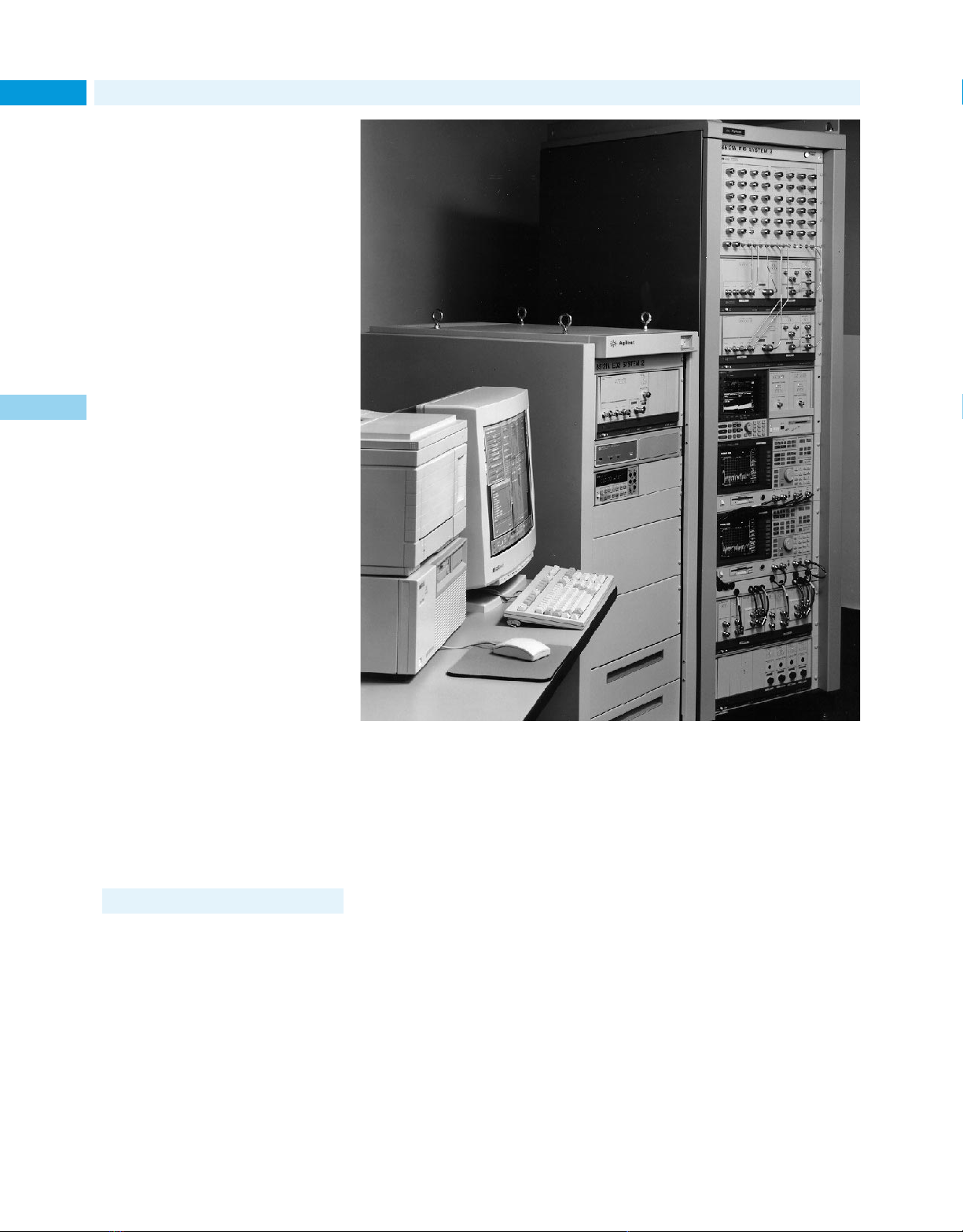
MMS Products
70000 Modular Measurement System
90
Overview
• Optimized for RF and microwave automatic
test systems
• Modular for easier system integration
• Wide variety of products and configurations
available
3
Agilent Technologies developed and supplies
an integrated rack of RF test equipment
for communication satellite payload test.
MMS signal generators, spectrum analyzers
and power meters were selected for a compact, EMC-rugged, highly-accurate, 1 GHz to
20 GHz broadband system. The 70611A
Attenuator/Switch Driver (an MMS system
module) is included providing a convenient
inter-face to a custom switch matrix.
Modular Measurement System
The Modular Measurement System (MMS) is
an open, industry standard controlled by a
consortium. The high-performance, modular
platform is especially suited for RF, microwave, and lightwave text applications. It
offers the lowest life-cycle cost when you
integrate, support or upgrade your system.
The MMS offers system designers a number
of advantages:
• A wide variety of over 50 modules offer
low frequency, RF, microwave and lightwave measurement capability.
• Easy system integration is aided by stan-
dard- and custom-switching modules,
plus an open architecture with design
tools that allow you to design and build
your own specialized modules.
• Easy-to-use displays allow you to operate
a system from local or remote locations,
and mainframes and displays can be separated by up to 1 kilometer.
• Electromagnetic compatibility (EMC)
design is optimized for microwave environments. Rugged mainframes, shielded
enclosures, grounding and a 40 kHz
switched power supply reduce emissions
and module-to-module interference.
• Automatic system control can be based on
DOS, BASIC or UNIX
• Compatibility with other open standards
allows you to make use of new and existing hardware, software and engineering
expertise. MMS and VXI combine easily
to solve complex measurement requirements. Both platforms continue to take
advantage of their own internal highspeed bus, but can be tied to a common
10 MHz clock reference. Both use common
trigger signal levels.
®
operating systems.
Maximize Your Investment
Several factors reduce MMS life-cycle costs:
• MMS integrates quickly, using off-theshelf mainframes, components and
software packages.
• MMS allows system configuration to provide just the right amount of measurement capability.
• Downsizing enhances ATE systems by
reducing rack space.
• A central, shared display allows operator
focus and monitors up to four instruments
at once in real time. This further reduces
rack space. The system will even work
without a display, saving more space and
reducing cost.
• Built-in diagnostics and modularity team
up to maximize system uptime, allowing
the best use of your investment.
70000 Modular Measurement System
Agilent offers a variety of products and services to help you customize your entire system. Multiple support alternatives allow you
to customize the logistics of each system to
fit installation needs. With MMS, you are
assured of the highest performance and best
customer support—today, and in the years to
come. Your Agilent sales representative can
help you configure the best solution for your
specific application.
The following pages highlight selected
components and systems in the 70000 family.
A complete listing of all MMS products and
most MMS products from other suppliers
with full descriptions, specifications and
services is also available on our web site:
www.agilent.com
Page 91

MMS Products
71451B
71400C with 70810B
70000 MMS Product Information
Mainframes and Displays
Product Description
70001A 8-slot mainframe for MMS plug-in modules
System Mainframe
70205A Display Compact, 3-slot module format
70004A Integrated mainframe and display
Color Display and 4 available module slots
Mainframe
Instruments
Choose from instruments that are single modules or multiple modules
configured into a system.
Sources
Product Description
71708A Microwave Excellent LO substitute for radar, phase noise
Source, 2.4 to 25.8 GHz measurement systems; test source for
70428A Microwave 600 MHz frequency resolution (0.1 Hz option)
Source Module, Up to +16 dBm output power
2.4 to 25.8 GHz 8-slot system includes mainframe display;
receiver test systems
4-slot module
Signal Analyzers
Product Description
70100A Single-channel module
Power Meter, 1-slot width
100 kHz to 50 GHz
70110A 3 1⁄2 to 6 1⁄2 digits of resolution
Digital Multimeter 2-slot width
P 70120A 100 MHz, 200 MHz, 2.4 GHz inputs
Universal Counter 1-slot width
70703A Digitizing 4-input, 2-channel operation 500 MHz
Oscilloscope 2-slot width
71500A Microwave 2-channels, sampler-based, internal trigger
Transition Analyzer, Time-domain measurements with FFTs
DC to 40 GHz
71707A Microwave Translates microwave signals
Downconverter, to RF frequencies for phase
2 GHz to 26.5 GHz noise measurements
70427A Microwave
Downconverter Module,
2 GHz to 26.5 GHz
Modular Measurement System
Spectrum Analyzers and Receivers
Product Description
All 70000 series 10 Hz minimum bandwidth
spectrum analyzers 90 dB calibrated display range
offer the following: 0.1 ppm frequency stability
71100C RF Synthesized, high performance
Spectrum Analyzer, RF spectrum analysis
100 Hz to 2.9 GHz –134 dBm sensitivity, –156 dBm
71209A Microwave Continuous sweeps from 100 Hz to
Spectrum Analyzer, 26.5 or 40 GHz
100 Hz to 26.5 GHz –138 to –128 dBm sensitivity across
71209A Option Z40 –107 dBm at 40 GHz (Option Z40)
Spectrum Analyzer, Built-in external mixer interface for
100 Hz to 40 GHz mm applications
71210C Microwave Fundamentally mixed, highest microwave
Spectrum Analyzer, performance
100 Hz to 22 GHz –139 dBm sensitivity at 1 GHz; –133 dBm
71910A Includes 71209A/P
Lightwave and Communication
Product Description
71400C Lightwave Calibrated measurement of intensity
Signal Analyzer, modulation from 100 kHz to 22 GHz
100 Hz to 22 GHz 1200 to 1600 nm operation
71401C Lightwave RIN measurements to –165 dB/Hz
Signal Analyzer, Interferometer for laser linewidth and
100 Hz to 2.9 GHz chirp measurements
70810B Lightwave 2-mainframe systems with 4 slots
Signal Analyzer available
Module
71450B Optical Spectral measurements from 600 to
Spectrum Analyzer 1700 nm
71451B Optical Real-time sweep rates
Spectrum Analyzer –90 dBm sensitivity, 60 dB dynamic range
71452B Optical Optional current source and white
Spectrum Analyzer light source
71501C Jitter Expanded measurement range:
Analysis System 50 Mb/s to > 12 Gb/s
with preamplifiers
the frequency range (71209A/P);
2-mainframe system with 5 slots
at 22 GHz; –155 dBm at 22 GHz with
(750 to 870 nm option 850)
Systems based on 71210C spectrum
analyzer
Double-pass monochromator
Wavelength and amplitude calibration
across full measurement range
5 modes of operation (71452B)
1 mainframe system with color display
Jitter transfer, tolerance, output/
generation
Test systems, networks, modules or
components, MUX/DEMUX
Eye-diagram and analysis capability
91
70000
3
Internet URL www.agilent.com/find/tmc Product & Order Info See page 604
Page 92
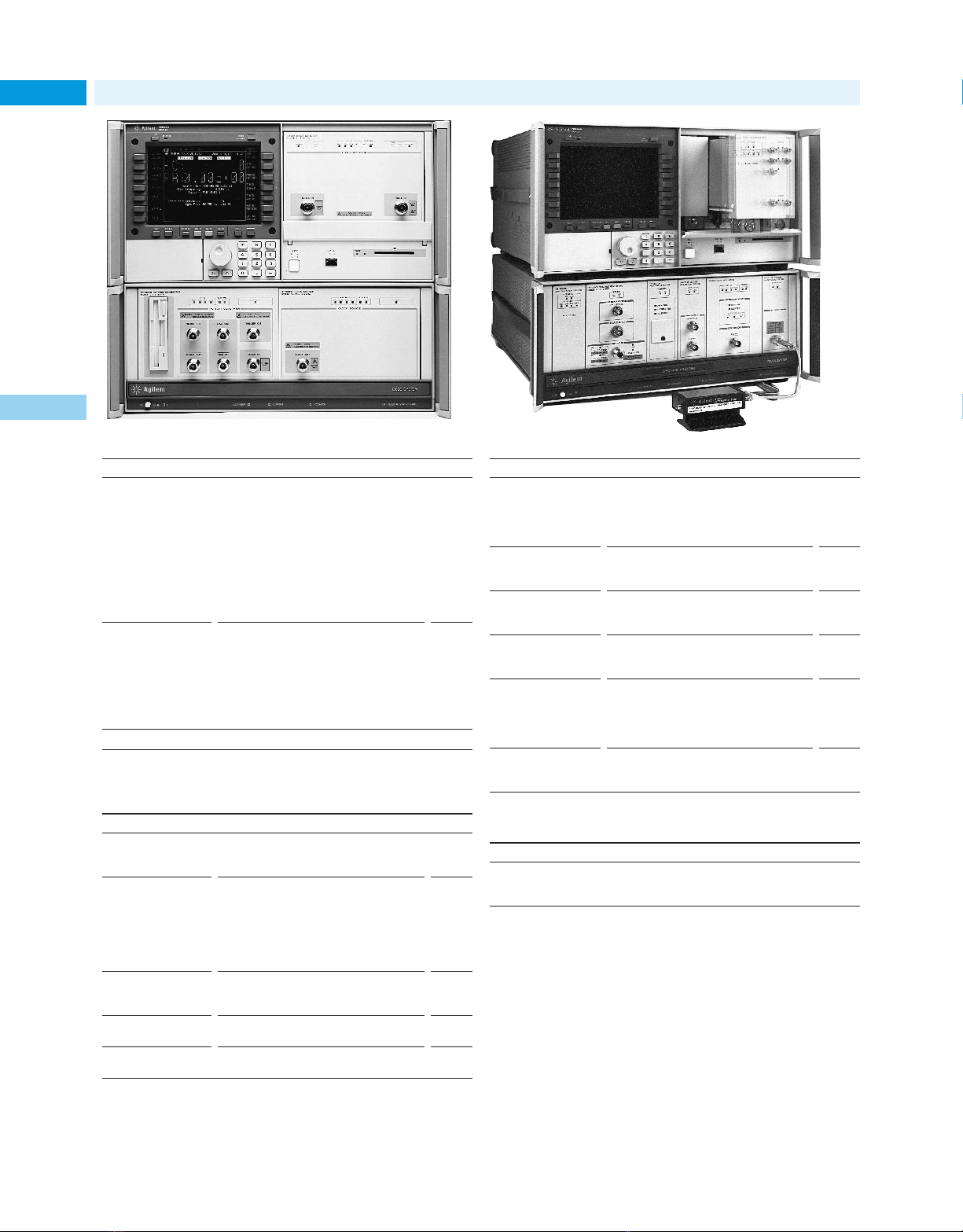
70000
MMS Products
Modular Measurement System (cont.)
92
3
71604B MMS System with 70612A
Product Description
71603B Gigabit 100 Mb/s to 1 Gb/s pattern generation
Error Performance and error performance analysis
Analyzer Low-phase-noise clock source
71604B Pattern 4 Mb with screen-based editor
Generator Ability to trigger anywhere in pattern
71612A Series 100 Mb/s to 12 Gb/s pattern generation
Gigabit Error and error performance analysis
Performance 8 Mb programmable pattern
Analyzers and Pattern Fast transition times, low jitter
Generators Burst-mode capability for fiberloop testing
POA = Price on application.
User-programmable patterns up to
Variable clock/data delay
Automatic setting of threshold and
decision point
True complementary outputs
2-mainframe systems with color display
Four sub-rate outputs
Location of specific errored bits
2-mainframe systems with color display
System Building Blocks
Configure an instrument or system for unique applications using
off-the-shelf modules.
Product Description
70310A 10 MHz to 100 MHz precision reference
Precision Frequency 1-slot width
Reference
70620B Boost sensitivity of analyzers by
Preamplifier, 15 to 25 dB
1 GHz to 26.5 GHz –156 dBm sensitivity at 2.9 GHz
70621A Optional 100 kHz low-end frequency
Preamplifier, Built-in switches for preamplifier bypass
100 kHz to 2.9 GHz
70900B Master control module for
Local Oscillator spectrum analyzers
70860A High-speed controller board upgrades
Upgrade Kit 70900A with features of 70900B
70861A RAM/ROM board upgrades firm-
Upgrade Kit ware to 70900B capabilities
–150 dBm sensitivity at 22 GHz
2-slot width
Product Description
70902A IF Section, Adds signal processing elements for
10 Hz to 300 kHz spectrum analyzers
70903A IF Section,
100 kHz to 3 MHz
70911A IF Section, Used in 71910A wide bandwidth
10 MHz to 100 MHz receiver
bandwidths 2-slot width
70904A RF Section, Broadband input conversion for
100 Hz to 2.9 GHz spectrum analyzers
70908A RF Section, Fundamentally mixed broadband
100 Hz to 22 GHz input conversion for analyzers
70909A RF Section, Diode-pair mixing, built-in preamp100 Hz to 26.5 GHz lifier for improved sensitivity
70910A RF Section, YIG tuned filter (70910A)
100 Hz to 26.5 GHz 2-slot width
70907B Interface for external mixers
External Mixer 1-slot width
Interface Module
1-slot width
1-slot width
2-slot width
Switchable bypass filter around
System Integration
Quickly integrate your test system using these resources and tools.
Product Description
70611A Controls up to 31 electro-mechanical
Attenuator/ mechanical switches or attenuator
Switch Driver 1-slot module
Service and Support
The MMS offers many support alternatives. The sytem design allows
modules to be exchanged in the field without loss of system calibration. For multiple-module systems, you can add new modules or
replace existing ones and run the one-button internal calibration
routine. Spares can be stocked based on the MTBF of individual
modules— often greater than 15,000 hours. Many MMS instruments
have built-in or downloadable diagnostic routines for locating faults.
And Agilent provides for return-to-factory repair and calibration of
systems, and offers MIL-STD-45622A certification that is valid for
up to three years.
Page 93
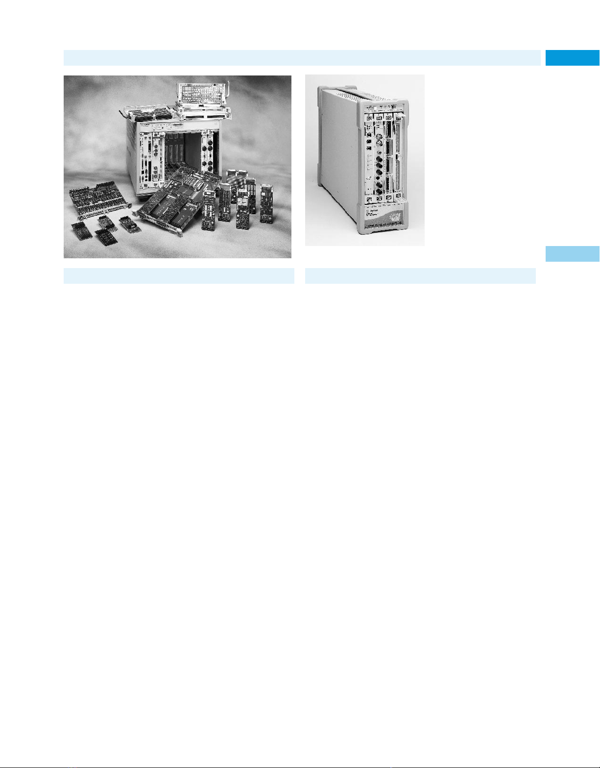
VXIbus Products
VXIbus Introduction
In 1987, a consortium led by several major test and measurement
manufacturers, including Hewlett-Packard, introduced VXIbus, a
new standard modular instrument architecture. VXIbus was developed to meet the needs for portable applications, particularly for the
military, and to provide an industry-standard instrument architecture with an interface speed significantly higher than that of the
GPIB interface. The design of this new architecture allowed the integration of VXIbus products into traditional GPIB test systems and
for standalone applications. Today, the VXIbus Consortium continues to refine the VXIbus standard and Hewlett-Packard remains an
active member.
Since the inception of VXIbus, other standards have been developed, which reduce users’ dependence on any one vendor. This lowers
the risks and provides maximum investment protection in hardware
and software purchases and system development. Agilent’s VXIbus
products support the industry-accepted VXIplug&play instrument
1
. One set of these standard drivers for the MS Windows envi-
drivers
ronment, for example, is supported by any of several popular software
packages: Agilent VEE, Microsoft C/C++, Visual Basic, Borland C/C++,
and NI Lab Windows. Other supported environments are Windows
95/NT, HP-UX, and SUN-OS.
Compact size, high throughput, and flexibility best characterize VXIbus. Today you can use VXIbus products to build a variety of
test systems from portable testers for field use and remote data
acquisition applications to high-performance data acquisition and
functional test systems. While some systems are entirely VXIbus
products, many users are integrating VXIbus along with traditional
GPIB instruments. Today VXIbus manufacturers and numerous
third-party integrators now are offering dedicated measurement
solutions using the VXIbus platform. Agilent offers several integrated products based on VXIbus.
The pages which follow give a brief overview of the VXIbus
Standard and a list of VXIbus products offered. For additional
configuration and product ordering information, separate documents are available. For a free Agilent Test System and VXI Products Catalog, in the USA call 1-800-452-4844 or visit our web site:
www.agilent.com/find/vxi
1
HP (now Agilent) joined the VXIplug&play Alliance in 1994 and has contributed to the
definition of its industry-standard instrument drivers now provided by numerous VXI
manufacturers.
75000 VXIbus Family
The E8408A is Agilent’s smallest footprint, lowest-priced C-size mainframe.
The VXIbus Architecture
VXIbus is defined around the highly popular VMEbus architecture
known for its excellent computer backplane. High-speed data rates
of 40 MB/s along with the necessary communication protocols make
it ideal for building instrument systems for high throughputs.
VXIbus incorporates the ease-of-use features of intelligent GPIB
instruments (for example, ASCII-level programming) into its message-based devices. It also takes advantage of the high-throughput
capability of VMEbus devices which are programmed and communicate directly in binary.
Although VMEbus is an excellent computer backplane, it is not
adequate for instrumentation without further standardization. The
VXIbus Consortium fully defined the operating environment for
instrumentation modules. All VXIbus mainframes must state how
much power and cooling they provide. And all VXIbus modules must
state how much power and cooling they require. Also, there are strict
limits on how much conducted and radiated interference is allowed
between modules. These parameters allow you to easily configure a
workable system.
VXIbus systems provide backplane management and resource
management functions. Slot 0, a unique physical location in every
VXIbus mainframe, handles the backplane by providing clock signals, data movement arbitration, and more. The Resource Manager
program configures the modules for proper operation whenever the
system is powered on.
Mechanical and Electrical
The VXIbus specification defines a scalable family of four module
sizes. The two smaller sizes, A and B, are the defined VMEbus module sizes, and are true VMEbus modules in every sense of the word.
The two larger sizes, C and D, are additional sizes to allow higher
performance instrumentation. Increased module spacing in the Cand D-size systems makes it possible to fully shield sensitive circuits
for high-performance measurements. VXIbus is a scalable architecture, and allows smaller module sizes to fit into larger mainframes.
VXIbus provides other resources for instrumentation. These
include additional power supply voltages for powering analog and
ECL circuits, and implementation buses for measurement synchronization and triggering. Included are an analog summing bus and a
set of local bus lines for private module-to-module communication.
Additionally, stringent EMC and noise requirements are specified to
maintain an interference-free environment for sensitive instrumentation.
VXIbus specifies three 96-pin DIN connectors: P1, P2, and P3
(page 94). The P1 connector, the only mandatory connector in
VMEbus or VXIbus, carries the data transfer bus (up to 24 bits
addressing and 16 bits data), the interrupt buses, and some power.
The optional P2 connector, available to all card sizes except A-size,
expands the data transfer bus and provides the additional resources
as shown with particular pin assignments. The local bus indicated is
a powerful feature provided by VXIbus. This flexible daisy-chain bus
structure allows for adjacent modules to conduct private, highspeed communication.
93
Overview
3
Internet URL www.agilent.com/find/tmc Product & Order Info See page 604
Page 94
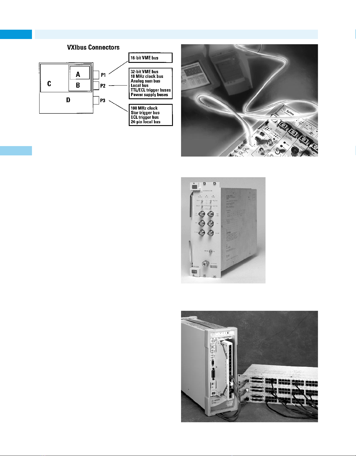
Overview
VXIbus Products
75000 VXIbus Family (cont.)
94
Power and Cooling
VXIbus specifies a set of guidelines to ensure adequate cooling.
3
Every vendor’s mainframe specifications sheet provides cooling
specifications for worse-case module configuration. Available airflow as a function of the maximum allowable pressure differential
across any module is specified. This is matched against the specified
airflow and pressure parameters specified for each module.
Values of peak dc current and peak-to-peak dynamic current
are specified for each module. The system integrator can match the
total module current loading to the capacity of the mainframe. The
dynamic current specification assures ripple-free noise on the mainframe’s power supply lines.
The E8491B PC to VXI Link provides IEEE-1394 (FireWire) interface capability to
your VXI test system.
Communications
A more standardized set of communication protocols is defined for
VXIbus systems to handle autoconfiguration, resource management,
and device communication. The Resource Manager, a message-based
commander, takes care of the configuration tasks. It sets up the
shared address space, manages the system self-test, creates the commander-servant hierarchies, and then releases the system for operation fully configured.
A message-based device, which communicates directly in SCPI
(ASCII), is commonly the most intelligent VXIbus device. Typically it
uses a microprocessor and is more costly than a register-based
device, but is easier to integrate into a VXIbus system. Most message-based devices provide moderate throughput performance in a
VXIbus system.
The most basic level of communication is that handled through
register-level (binary-level) reads and writes to the registers of the
register-based device (in some instances, direct-register access is
provided on a message-based device to improve throughput performance). The register-based device is often controlled by an intelligent
message-based device, its commander (command module or embedded controller). The commander interprets SCPI (ASCII) instrument
commands converting them into binary for communication to the
register-based device. To avoid the speed-reducing effects of the SCPI
interpretation, compiled SCPI is used to compile the SCPI instrument commands before runtime. Runtime speeds, then, are commensurate with binary-level speeds as though the user had programmed
directly in binary.
An IEEE-488-to-VXIbus interface is also defined in the VXIbus
specification allowing for easy integration of VXIbus and GPIB products into one system. Agilent’s Command Module (E1406A), for example, provides the GPIB connection for interfacing to an external GPIB
controller. For high-throughput systems, an industry-standard interface, IEEE-1394 (FireWire), is provided in the E8491B PC link to VXI.
The E6432A VXI Microwave Synthesizer
delivers CW signals with low phase noise and excellent spectral purity.
Summary
The benefits of industry-standard VXIbus systems are these:
• Downsizing to save costly rack space
• High-performance, high-throughput measurement capability
• Reduced time and cost for system development
• Reduced dependency on proprietary architectures
The following pages provide a listing of Agilent’s VXI products. For
product details and specifications, please refer to Agilent’s Test
System and VXI Products Catalog. To obtain a copy, please visit our
web site:
www.agilent.com/find/vxi, or in the U.S. call 800-452-4844.
The E1529A Remote Strain Conditioning Unit simplifies structural testing of designs
that require many channels of strain measurement.
Page 95

VXIbus Products
75000 VXI Products Information
Model No. Description
Mainframes
E8408A 4-Slot, C-Size VXI Mainframe with options
E8401A Low-cost, Medium Power C-Size VXI
E8403A High Power, C-Size VXI Mainframe,
E8404A High Power, Enhanced Monitoring C-Size
E1401B High-Power Mainframe, C-size,
E1421B Mainframe, C-size, 6-slot; racking
E1300B/01B Mainframes, B-size, 7-slot; built-in
Controllers
E1406A Command Module, C-1, message-based
E6234A VXI Pentium®PC Controller WIN 95/NT
E6237A VXI Pentium®PC Controller LynxOS
E9850A VXI Embedded PC Controller, 450 MHz WIN NT 3
E4208D SCSI Disk, C-1, 4 GB hard drive,
E3249B SCSI System Disk, C-2, 4.3 GB
N2216AA Data Disk and SCSI-2 Interface, VXI 3
Interface
E8491B IEEE-1394 PC Link to VXI C-Size, Opt 001
E1482B VXIbus-to-MXIbus Extender, C-size,
E1489C EISA/ISA-to-MXI interface; For direct
E2749A Fibre Channel Data I/O Module
Application Software
E2120G VEE Pro 6.0, Graphical Programming Language, 3
E2060C HP BASIC for Windows: based on the
to add GPIB Command Module or
IEEE-1394 Slot-0 Interface
Mainframe, 13-Slot
13-Slot, standard monitoring.
VXI Mainframe, 13-Slot
13-slot; racking options available
options
68000 processor and IEEE-488 and
RS-232 interfaces; Options: dc power,
memory, mass storage, IBASIC
commander, SCPI translator for registerbased modules; optional expanded memory
available
1.44 MB, 3.5-inch floppy
hard drive, 4 GB DAT tape
1-slot; Connect two or more VXI mainframes together, or interface to external
MXIbus controllers
VXI backplane interface to HP 9000
series 700 controllers
Windows version
popular HP Rocky Mountain Basic language
75000 VXI Products
Model No. Description Price
Measurement
E1312A, 6.5 Digit Multimeter, B-2/C-1, RB/MB, Vac/
E1412A dc, lac/dc, 2/4-w ohms, frequency, period
E1411B, 5 Digit Multimeter, C-1/B1, RB, Vdc/ac,
E1326B 2/4-w Ω, temperature
E1428A 1GSa/s Digitizing Oscilloscope, C-1, MB,
E1430A 10 MSa/s A/D with DSP, C-1, RB 1-Ch.,
E1432A 16-Ch. 51.2 kHz Digitizer plus DSP C-1, RB,
E1433B 8-Ch. 196 kSa/s Digitizer plus DSP, C-1, RB,
E1437A 20 MSa/s Digitizer with DSP, C-1, MB/RB,
E1438A, 100 MSa/s Digitizer with DSP, C-1, RB, 1-Ch., 3
E1439A 95 MSa/s Digitizer with DSP, 70 MHz IF input, 3
SCMVX008 Digital Signal Processor,Dual 60 MHz,
E3242A Breakout Box accessory interfaces
E3243A Breakout Box accessory interfaces
E3245A 12-channel mini-phone plugbreakout
E1413C 64-Ch. Scanning A/D, C-1, RB, 16 b,
E1415A Algorithmic Closed-Loop Controller, C-1,
E1419A Multi-Function Measurement and Control
E1420B High-Performance Universal Counter,
E1332A 4-Ch. Counter/Totalizer, B-1, RB, 4 MHz
E1333A 3-Ch. Universal Counter, B-1, RB, 1 GHz
E1740A 150 MHz Time Interval Analyzer, C-2,
E1416A Power Meter, C-1, MB, 1-Ch., 110 GHz
E1485C Digital Signal Processor, C-1, 40 MHz
SCMVX008 Digital Signal Processor, C-1, two 60 MHz
E1529A Remote strain conditioning unit
E1563A, 2-, 4-Ch., 800 kSa/s Digitizers
E1564A
2-Ch., 8 b, 250 MHz bw
23 b, 4 MHz bw, 24 digital filters, FIFO
16-bit, 4-32 MB FIFO, digital anti-alias filters
16 b, digital anti-alias filters, 4-32 MB FIFO,
88 kHz bw
1-Ch., 23 b, 8 MHz bw, 24 digital filters, FIFO
12 bit, 40 MHz BW, AAF, 17 dig. filters, FIFO
C-1, RB, 1-Ch., 12 bit, 36 MHz BW, AAF, 17 dig.
filters, FIFO
Tms 320, C40 DSP with 6 expansion slots
charge and IEPE accelerometers
to E1432A/33AVXI Digitizers
microphones and IEPE accelerometers
to E1432A/33A VXI Digitizers
box to 26-pin high density connector.
100 kSa/s
RB, 16 b A/D with signal conditioning
C-1, MB, 2-Ch., 200 MHz/2 GHz
MB, 80 M rdgs/s, 100 ps rms
Motorola 96002 DSPwith 4 expansion slots
TMS320C40 DSPs with 6 expansion slots
95
3
M-Modules
E2251A C-Size M-Module Carrier
E2261A Quad RS-232 Interface M-Module
E2270A 16-Ch. Form A Switch M-Module
E2271A 4x4 Matrix Switch M-Module
E2272A Dual 8-to-1 Relay Multiplexer M-Module
E2273A 8-Ch. Form C Switch M-Module
E2290A 16-bit Digital I/O M-Module
Internet URL www.agilent.com/find/tmc Product & Order Info See page 604
Page 96

VXIbus Products
75000 VXI Products (cont.)
96
75000 VXI Products Information
Model No. Description
Sources and Amplifiers
E1445A Arbitrary Function Generator, C-1, MB,
E1328A 4-Ch. D/A Converter, B-1, RB, 16 b,
E1434A 4-Ch. 65 kSa/s Arbitrary Source, C-1, RB,
E1418A 8/16-Ch D/A Converter, C-1,
E1441A Arbitrary Waveform Generator
E1750A/52A Broadband Freq./Pulse Amplifiers, C-1,
3
E6432A Microwave synthesizer
E8311A C-1,165 MHz/Pulse/Pattern Generator,
E8312A C-1, 330 MHz/660 Mbit/s, Pulse/Pattern
Digital
E1330B Quad 8-bit Digital I/O, B-1, RB, 32-Ch.,
E1339A 72-Ch. Open-Collector Dig Out/Relay Driver
E1452A Pattern I/O Module, C-1, RB 32-Ch., Input or
E1458A 96-Ch. Digital I/O, C-2, RB, 96-Ch., I or O, TTL
E1459A 64-Ch. Isolated Dig Input/Interrupt
Switches—Relay Multiplexer
E1343A 16-Ch., 3-w, B-1, RB, Reed, < 10 µV, 250 V,
E1344A 16-Ch., T/C, 3-w, B-1, RB, Reed, < 10 µV,
E1345A 16-Ch., 3-w, B-1, RB, Reed, < 4 µV, 120 V,
E1346A 48-Ch., 1-w, B-1, RB, Reed, < 50 µV, 120 V,
E1347A 16-Ch., T/C, 3-w, B-1, RB, Reed, < 4 µV,
E1351A 16-Ch., 2-w, B-1, RB, FET, < 25 µV, 16 V,
E1352A 32-Ch., 2-w, B-1, RB, FET, < 25 µV, 16 V,
E1353A 16-Ch., 1-w, B-1, RB, FET, < 25 µV, 16 V,
E1460A 64/32/128-Ch. 2/3/1-w, C-1, RB, Armature/L,
E1476A 64-Ch. 3-w, 32-Ch. 4-w, C-1, RB, Reed,
E8460A 256-Ch. Reed Relay Multiplexer
E8462A 256-Ch. Armature Relay Multiplexer
13 b, 40 Msa/s, 10.2 V p-p (50 Ω), sweep,
waveforms: arb, sine, square, ramp;
Optional waveform software available
1.3 kSa/s, 10.92 V dc
16-20 bit,10 V, sine, 25.6 kHz, bw, random,
swept sine, 4-32 MB RAM FIFO
RB programmable isolation, ± 16 V,
± 20 mA, 16 bit 1 kHz update rate
RB, 10 MHz/10 M PPS, 6-Ch., sine/pulse,
1 Vrms (50 Ω)
(10 MHz to 20 GHz with 1 Hz resolution)
2 output channels, 10Vpp (50 Ω into 50 Ω),
20Vpp (1K Ωinto 50 Ω), 16kbit patterns,
5ps timing resolution, 0.01% frequency
accuracy, variable transition times (2 ns to 200 ms)
Generator, 2 output channels, 3.8Vpp, 16kbit
patterns, 5ps timing resolution, 0.01% frequency
accuracy, 0.8ns or 1.6ns fixed transition times
I or O, TTL, 325 kb/s
Output, TTL/CMOS, 20 M patterns/s
10 MHz, 50 mA
250 V, 10 MHz, 50 mA
10 MHz, 50 mA
10 MHz, 50 mA
120 V, 10 MHz, 50 mA
100 kHz, 1 mA
100 kHz, 1 mA
100 kHz, 1 mA
< 7 µV, 60 V, 1 MHz, 1 A
voltage, current, temperature (T/C)
Model No. Description
Switches—RF Relay Multiplexer
E1366A Dual 1x4, 50 Ω, B-1, RB, Armature,
E1367A Dual 1x4, 75 Ω, B-1, RB, Armature,
E1470A 60-Ch. Cascade RF Multiplexer, 60:1 to
E1472A/73A Six 1x4, 50 Ω, C-1, RB, Armature,
E1474A/75A Six 1x4, 75 Ω, C-1, RB, Armature,
< 6 µV, 42 V, 1.3 GHz, 1A
< 6 µV, 42 V, 1.3 GHz, 1A
20 3:1, 50 Ω, C-1, RB, Armature, < 6 µV,
30 V, 500 MHz (3:1), 450 mA (AC)
< 6 µV, 42 V, 1.3 GHz, 1A
< 6 µV, 42 V, 1.3 GHz, 1A
Switches—Microwave
E1368A 50 Ω, 3-Ch. Form C (SPDT), B-1, RB,
E1369A Switch Driver, B-1, RB, drives switches
E1370A Switch/Attenuator Driver, B-2, RB, drives
Armature, 18 GHz
up to 26.5 GHz
switches up to 26.5 GHz
Switches—Matrix
E1361A 4x4, 2-w, B-1, RB, Armature, < 14 µV,
E1465A 16x16, 2-w, C-1, RB, Armature/L, < 5 µV,
E1466A 4x64, 2-w, C-1, RB, Armature/L, < 5 µV,
E1467A 8x32, 2-w, C-1, RB, Armature/L, < 5 µV,
E1468A 8x8, 2-w, C-1, RB, Armature/L, < 7 µV,
E1469A 4x16, 2-w, C-1, RB, Armature/L, < 7 µV,
250 V, 10 MHz, 1 A
200 V, 10 MHz, 1 A
200 V, 10 MHz, 1 A
200 V, 10 MHz, 1A
220 V, 10 MHz, 1 A
220 V, 10 MHz, 1A
Switches—General Purpose
E1364A 16-Ch., Form C (SPDT), B-1, RB, Armature,
E1463A 32-Ch. Form C (SPDT), C-1, RB, Armature,
E1442A 64-Ch., Form C/A (SPDT), C-1, RB, Armature,
< 7 mV, 250 V, 10 MHz, 1 A
< 7 mV, 125 V, 10 MHz, 5 A
< 170 mV, 150 V, 10 MHz, 1 A
Optical Switches
E4502A/ 2-1x4 / 1-1x16 / 2-1x8 Optical Switches,
03A/04A C-1, RB
Special Purpose Modules
WJC9119S/M High Frequency Tuner (down converter)
C-1 means C-size, 1 slot; B-2 means B-size, 2 slot; RB means Register-based;
MB means Message-based, DIO means digital input/output
C-2, RB, 32 MHz
Page 97

System Switches
Agilent’s switch family provides you with long-lasting quality, reliability, and performance for your small, medium, or large test system.
Agilent offers modular test systems with plug-in switch modules and
dedicated instrumentation and fixturing.
VXIbus Modular Test Systems
The 75000 B- and C-size VXI test systems provide a modular architecture with numerous switches and instruments. These systems
contain the most versatile switching solutions in the industry-standard VXI format. The C-size VXI system is the most popular architecture for high-performance, high-speed applications that require
both switching and instrumentation. The B-size VXI system is ideal
for applications requiring switching and some instrumentation.
• General purpose
• Matrix
• Multiplexers/scanners
• Microwave/RF
• Full line of instruments (refer to pages 95–96 for more
information on VXI test systems)
3499 for Manufacturing Test and Desktop Switching
The Agilent 3499A/B switching/control systems are ideal for use in
manufacturing test application where a high-speed, high density
switching solution is needed. The 3499 family includes two mainframes, one with two slots and the other with five slots, it also includes
26 plug-in modules, making it cost effective for any size application.
Existing 3488A users can easily upgrade to the 3499A because both the
Signal Routing and Measurement
hardware and software are compatible. The following modules are
available for the 3499A/B:
• 40-channel multiplexer
• 4 x 8 Matrix
• 12 General Purpose + 3 high current General Purpose
+ 16-bit Digital I/O
• 4 x 4 Matrix + 16-bit Digital I/O
• 40-channel high speed multiplexer
• 8-channel 8 A General Purpose
• 40-channel General Purpose
• 32-bit Digital I/O
• 10-channel 1000 V multiplexer
• 32-bit Isolated Digital I/O + 2 DACs
• 3.5 GHz Dual 1 x 4 multiplexer
• Quad 1 x 2 optical multiplexer, SC/APC
• Dual 1 x 4 optical multiplexer, SC/APC
Refer to page 98 for more information on the 3499A/B.
34970A for Low-Cost Switching
The 34970A Data Acquisition/Switch Unit is ideal for cost-sensitive
applications with small- to mid-sized channel count requirements.
The three-slot mainframe offers eight switch and control modules
which cover a broad spectrum of capabilities.
• Low-frequency multiplexing to 300 V
• 2 GHz RF switching (both 50 and 75 ohms)
• Matrix switching/General Purpose/Form-C switching
• Digital IO/Analog output/Event counting
Refer to page 154 for more information on the 34970A.
97
VXI Series
B/C-size
34970A
3499A/B
3
The Switch Module Selection Table on this page provides comparative information for each of the VXIbus switches.
Model # Description Size, Switching Thermal Max. Volts Bandwidth Current Closed Channel
Relay Multiplexers
E1343A 16-Channel, 3-wire B, 1 Reed relay <10 µV 250 V 10 MHz 50 mA 100 ±10%
E1344A 16-Channel T/C, 3-wire B, 1 Reed relay <10 µV 250 V 10 MHz 50 mA 100 ±10%
E1345A 16-Channel, 3-wire B, 1 Reed relay <4 µV 120 V 10 MHz 50 mA 100 ±10%
E1346A 48-Channel, 1-wire B, 1 Reed relay <50 µV 120 V 10 MHz 50 mA 100 ±10%
E1347A 16-Channel T/C, 3-wire B, 1 Reed relay <4 µV 120 V 10 MHz 50 mA 100 ±10%
E1351A 16-Channel, 3-wire B, 1 FET <25 µV 16 V 100 kHz 1 mA <3.1 k
E1352A 32-Channel, 1-wire B, 1 FET <25 µV 16 V 500 kHz 1 mA <3.1 k
E1353A 16-Channel, T/C 3-wire B, 1 FET <25 µV 16 V 500 kHz 1 mA <3.1 k
E1460A 64 Channel Relay Unit C, 1 Armature, L <7 µV 220 V 3/10 MHz 0.3, 1 A <1.5
E1476A 64-Channel, 3-wire C, 1 Reed relay <2 µV 120 V 100 kHz 35 mA 100 ±5%
E8460A 256-Ch. Relay Multiplexer C, 1 Reed relay 50 µV 200 V 100 kHz 300 mA <3
E8462A 256-Ch. Armature MUX C, 1 Armature 3µV 250 V — 2 A <0.5
E2272A Dual 8 x 1, MUX M-Mod DPST, L <3 µV 60 V >10 MHz 2 A 0.2
RF Multiplexers
E1366A Dual 1 x 4, 50 Ω B, 1 Armature <6 µV 42 V 1.3 GHz 1 A <1
E1472A/73A Six 1 x 4, 50 Ω C, 1 Armature <6 µV 42 V 1.3 GHz 1 A <1
E1367A Dual 1 x 4, 75 Ω B, 1 Armature <6 µV 42 V 1.3 GHz 1 A <1
E1474A/75A Six 1 x 4, 75 Ω C, 1 Armature <6 µV 42 V 1.3 GHz 1 A <1
E1470A 60-Channel RF Cascade C, 1 Armature — 30 V 500 MHz 400 MA <1.5
Microwave
Switches
E1368A 50 Ω, 3-Ch. Form C (SPDT) B, 1 Armature — — 18 GHz — —
E1369A Switch Driver B, 1 – — — Up to 26.5 GHz — —
E1370A Switch/Attenuator Driver B, 2 – — — Up to 26.5 GHz — —
Matrix Switches
E1361A 4 x 4, 2-wire B, 1 Armature <14 µV 250 V 10 MHz 1 A <1.5
E1465A/66A 16 x 16/4 x 64, 2-wire C, 1 Armature, L <5 µV 200 V 10 MHz 1 A <1.8
E1467A 8 x 32, 2-wire C, 1 Armature, L <5 µV 200 V 10 MHz 1 A <1.8
E1468A 8 x 8, 2-wire C, 1 <7 µV 220 V 10 MHz 1A <1.5
E1469A 4 x 16, 2-wire C, 1 Armature, L <7 µV 220 V 10 MHz 1 A <1.5
E2271A 4 x 4 Matrix M-Mod DPST, L <3 µV 60 V >10 MHz — 0.3
General Purpose
Switches
E1364A 16-Channel Form C (SPDT) B, 1 Armature <7 µV 250 V 10 MHz 1 A <1.5
E1442A 64-Ch. Form C/A (SPDT) C, 1 Armature <70 µV 150 V 10 MHz 1 A <1.5
E1463A 32-Channel Form C (SPDT) C, 1 Armature <7 µV 125 V 10 MHz 5 A <0.25
E2270A 16-Ch. Form A Switch M-Mod SPST, L <3 µV 60 V >10 MHz 2 A <0.2
E2273A 8-Ch. Form C Switch M-Mod Armature <20 µV 60 V >10 MHz 1 A –
Multiplexer (1 x 3) (typical)
Slots Type Offset (DC) (–3 dB) Rating Resistance
(L-latching) (per ch.) (Ω , initial)
Internet URL www.agilent.com/find/tmc Product & Order Info See page 604
Page 98
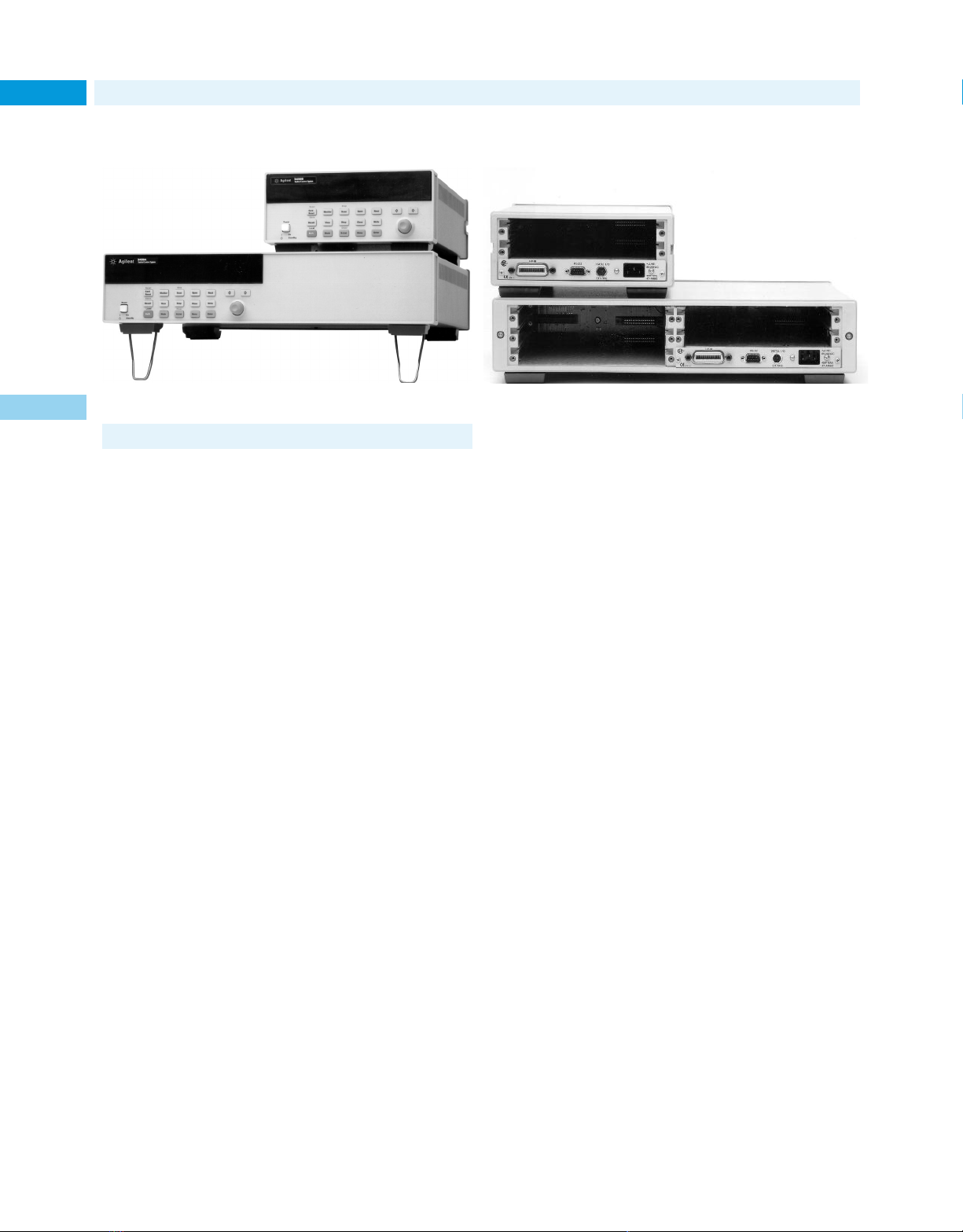
System Switches
Signal Routing and Measurement (cont.)
98
3499A
3499B
• Close/open 200 channels in parallel in 0.1 second
• 26 electronic and fiber-optical modules available
• Switching modules with built-in relay cycle counters
3499A/B front panel
3
3499A/B Switch/Control System
The Agilent 3499 family is a high speed, high density, switching solution for electronic/optical automated test (ATE) applications that provides a 30% cost and space savings over its predecessor—the 3488A.
It can scan at rate up to 300 channels per second, or open/close
200 channels in less than 0.1 second. The 3499A can accommodate
up to 5 plug-in modules, routing up to 200 channels in a test system.
The user can choose from 24 plug-in modules, to switch electronic
signals from DC to 26 GHz, 1mV to 1000V, and 1mA to 8A.
The 3499B is a half-rack-width, 2-slot mainframe, switching up
to 80 channels in ATE or desktop operations. Both units have a concise user interface that is extremely useful for manual operation on
the manufacturing floor or in desktop applications.
High Speed Switching
While traditional switching mainframes open/close relays in
sequence, the Agilent 3499A/B use innovative parallel driving circuits to open/close switches simultaneously. The 3499A can drive as
many as 50 channels in 25 ms. With the fast reed relays, the N2266A
multiplexer can scan at a speed up to 300 channel/second. The highspeed 3499A/B dramatically increase the test throughput of an automated test system.
Highly Reliable Switching
The switches are the linkage between the instruments and the DUT,
and are the central parts in a test system. Reliability is the most
important consideration when designing a switching system. If a
low reliable switching system is chosen, it will be the weakest link in
your test system, thus increasing your production down cost. When
designing the plug-in modules, we provided fail-safe protection circuitry and enough design margin to ensure its high reliability, especial the high current and high voltage switching modules.
• DC to 26.5 GHz, 1mA to 8A, 1mV to 1000V
• Easy wiring with connection kits
• Multi-function modules for space saving
3499A/B front panel
High Density Switches
The Agilent 3499 family allows the user to select a cost-effective configuration for a specific application. Newly designed high density
switch modules reduce cost by condensing a large number of channels on a single module. The 3499A contains five slots that accommodate up to 200 switching channels for those large applications on
the manufacturing floor. The 3499B contains two slots for switching
up to 80 channels, a cost-effective solution for small manufacturing
or desktop applications. Both units are designed for easy installation on a standard rack.
Ease of Maintenance
The built-in relay cycle counters on eleven newly-designed switching
modules help you predict relay end-of-life, thereby avoiding costly
production line down-time. The relay cycle counter automatically
counts every individual relay closure and stores the number in the
on-board non-volatile memory. A simple command recalls the total
number of cycles for individual relay, making preventative maintenance much simpler.
Ease of Wiring
The Agilent 3499 family provides two connection kits to reduce the
time and effort of wiring. Both the screw connection kits and
crimp & insert connection kits are detachable from the switching
modules, eliminating the need to rewire the connectors if a switching module is replaced. 3499 is also equipped with DIN96-to-D50
(25) cables for easy attachment to your DUTs and test instruments.
Applications
The 3499A/B with the diverse plug-in modules are an ideal switching solution for automated test system applications. Typical applications include the production test system of cellular phones, base
stations, antennas, pagers, printers, power supplies, optical, and
electronic components. You will discover that the Agilent 3499 family is the preferred highly reliable switching solution with its high
density plug-in modules, high switching speed, ease of wiring, ease
of maintenance, and low cost per channel.
Page 99

System Switches
Plug-in Module Description
40-channel high speed Multiplexer N2266A
The Agilent N2266A is a high speed multiplexer module for high
throughput production test system applications, scan speed is up to
300 channel/second. It can be configured as a 1-wire 80-channel, a 2wire 40-channel, or a 4-wire 20-channel multiplexer.
8-channel 8 A General Purpose N2267A
The N2267A is a highly reliable GP module for high current, low resistance switching applications, such as AC/DC power supply test. It can
also be used to switch AC (up to 250V) or DC power supplies, current
sources, and line powers.
10-channel 1000 V Multiplexer N2270A
The N2270A is a highly reliable 2-wire multiplexer. It can be used to
source voltage up to 1000V to any of ten DUTs or to monitor voltage
from different sources with a voltmeter. Applications include capacitor breakdown voltage test and high-resistance measurement of transformers, capacitors, relays, connectors, PCBs and cables.
Dual 1 x 4 RF (50 Ω 3.5 GHz) Multiplexer N2268A
The N2268A has two independent 1 x 4 multiplexers with SMA connectors, providing very low insertion loss, high isolation and excellent VSWR performance. The high isolation performance makes this
module ideal for RF signal measurements with spectrum analyzers,
network analyzers and GSM/CDMA test sets. Each group of four channels is isolated from the other and from the chassis to prevent ground
loops. The typical applications include 1.8/1.9 GHz wireless communication device, Bluetooth transceiver and L1/L2 GPS receiver test.
32-bit Isolated DIO+2 DACs N2269A
The N2269A multifunction module is a combination of two DACs, 16bit digital input and 16-bit digital output. The optically isolated module is designed for industrial automation, it provides excellent signal
integrity by eliminating ground noise.
40-channel Multiplexer N2260A
The N2260A can be configured as 1-wire 80-channel, 2-wire 40-channel, dual 2-wire 20-channel, or a 4-wire 20-channel multiplexer for
scanning or multiple-signal/instrument connection.
40-channel General Purpose N2261A
The N2261A is ideal for creating isolated control between circuits,
providing power control of DUTs, or control of stepping motors and
solenoids.
4 x 8 Matrix N2262A
The N2262A provides the most flexible way to connect a group of
test instruments to multiple test points on DUTs.
32-bit Digital I/O N2263A
The N2263A, with its 32 TTL compatible digital bits, and 3 handshake
lines, can be used to drive/control external devices, to monitor external status, or to communicate with other devices. It provides 3 modes
(Static, Strobe, Handshake) for different I/O control applications.
12 + 3 GP + 16-bit Digital I/O N2264A
The N2264A multi-function module is designed for applications that
require general purpose relays and up to 3 high current relays (5A
maximum) within one module for rack space saving. The 3 high current relays are very useful in applications where a few low resistance
channels are needed, such as in cellular phone or battery production
test system. There are also 16 bits of Digital I/O on this module.
Signal Routing and Measurement (cont.)
Quad Optical 1 x 2 Multiplexer, SC/APC N2280A
Dual Optical 1 x 4 Multiplexer, SC/APC N2281A
The 1 x 2 and 1 x 4 optical modules bring the flexibility of modular
switching to optical test system. Test engineers can set up an ATE
system with just enough optical switching channels to fit the current
application, and add more channels later as the application grows.
These two modules are ideal for SONET test, fiber-optical component test and fiber network monitoring. These modules are optically
passive, and operate independently of data rate, data format and
optical signal direction. The SC/APC connectors provide reliable
and easy connection to the modules.
4 x 4 Matrix + 16-bit Digital I/O N2265A
The N2265A is designed for applications that require 4x4 matrix and
16 bits digital I/O within one module for rack space saving.
10-channel Multiplexer 44470A
20-channel Multiplexer 44470D
10-channel General Purpose 44471A
20-channel General Purpose 44471D
Dual 1 x 4 RF Multiplexer 44472A
4 x 4 Matrix 44473A
16-Bit Digital I/O Module 44474A
Breadboard 44475A
7 Form-C Relay 44477A
18 GHz Microwave Switches 44476A
1.3 GHz 50 Ω RF Multiplexer 44478A
1.3 GHz 75 Ω RF Multiplexer 44478B
Microwave Relay Driver 44476B
This module can drive any following two 876XX coaxial switches.
Agilent coaxial switches that can be used are:
Coaxial Switch Ports Frequency
8762A, B, C, F 3 4 GHz to 26.5 GHz
8763A, B, C 4 4 GHZ to 26.5 GHz
8764A, B, C 5 4 GHz to 26.5 GHz
Notes: The 8762F is for 75 Ω signal switching.
Please choose option 011 when ordering above coaxial switches for the
coil voltage of 5 V DC. For details of Agilent 876xx specification, please
refer to p/n 5964-9527E.
3499A/B Mainframe Specification
Power Supply: 100 to 240 VAC universal input; 47 Hz to 440 Hz;
40 VA maximum
Operating Environment: 0˚ C to 55˚ C, <80% RH (0˚ C to 40˚ C)
Storage Environment: –40˚ C to +70˚ C
Size:
3499A: 89mm H x 426mm W x 348mm D (3.5 in x 16.8 in x 13.7 in )
3499B: 89mm H x 213mm W x 348mm D (3.5 in x 8.4 in x 13.7 in)
Net Weight:
3499A: 3.8 kg (8.4lbs);
3499B: 2.5 kg (5.5lbs)
Safety: Conforms to CSA, UL-1244, IEC 1010 Cat I
RFI and ESD: CISPR 11, IEC 80 1/2/3/4
Slot Capacity: 3499A: 5 slots; 3499B: 2 slots
Rear Panel Connectors: GPIB; RS-232; 8-pin Mini DIN
Trigger Source: External (9-pin Mini DIN); GPIB; RS-232
Built-in 4 digital I/O: Input: TTL compatible; Vout (H) ≤42V
Warranty: 1 year
99
3499A
3499B
3
Key Literature
Agilent 3499 Switching Family Data Sheet, p/n 5980-2797EN
Internet URL www.agilent.com/find/tmc Product & Order Info See page 604
Page 100

System Switches
3499A
3499B
100
Signal Routing and Measurement (cont.)
Please refer to the following table for plug-in modules selection.
Module Description Max. Max. Initial closed Thermal Bandwidth Connection Relay cycle
Multiplexer modules
N2266A 40-channel 200 V 0.5 <1 Ω <50µV 40 MHz T or C Yes
N2270A 10-channel 1000 V 1A <1 Ω <200µV 5 MHz Crimp & Insert Yes
N2260A 40-channel 200 V 1A <1 Ω <3µV 10 MHz T or C Yes
44470A 10-channel 250 V 2A <1 Ω <3µV 10 MHz T
44470D 20-channel 250 V 2A <1 Ω <3µV 10 MHz T
General purpose relay modules
N2267A 8-channel 250 V 8A <0.08Ω <3uV 20 MHz Crimp & Insert Yes
N2261A 40-channel 200 V 1A <0.5Ω <3uV 10 MHz T or C Yes
44471A 10-channel 250 V 2A <1 Ω <3uV 10 MHz T
44471D 20-channel 250 V 1A <1 Ω <3uV 10 MHz T
44477A 7-Form C 250 V 2A <1 Ω <3uV 10 MHz T
Matrix modules
N2262A 4 x 8 matrix 200 V 1A <1 Ω <3uV 10 MHz T or C Yes
44473A 4 x 4 matrix 250 V 2A <1 Ω <3uV 10 MHz T
Digital I/O modules
N2263A 32-bit TTL 42 V 0.6A – – – T or C
3
44474A 16-bit TTL 30 V 0.125A – – – T
Multi-function modules
N2269A 2 DAC 12V 10mA – – 20 KHz T or C
N2264A 12 GP 200 V 1A <0.5 Ω <3uV 10 MHz T or C Yes
N2265A 4 x 4 matrix 200 V 1A <1 Ω <3uV 10 MHz T or C Yes
Notes: GP = General Purpose; DIO = Digital I/O; T = Terminal Block; C = Cable
32-bit DIO TTL Compatible – – 3.5MHz T or C
3 GP 125 V 5A <0.1 Ω <3uV 10 MHz T or C Yes
16-bit DIO 42 V 0.6A – – – T or C
16-bit DIO 42 V 0.6A – – – T or C
voltage current channel offset (–3 dB) type counter
per chan. resistance per chan.
Modules Description Insertion loss Stability Repeatability Wavelength Connector Switching Time
Fiber-optical multiplexer modules (typical specs)
N2280A Quad 1 x 2 <0.5 dB ±0.03 dB ±0.003 dB 1310/1550 nm SC/APC 15 ms
N2281A Dual 1 x 4 <0.5 dB ±0.03 dB ±0.003 dB 1310/1550 nm SC/APC 15 ms
Modules Description Insertion loss Cross talk SWR Bandwidth Impedance Connector
RF & Microwave modules
N2268A Dual 1 x 4 <0.35 dB <-70 dB <1.20 3.5 GHz 50 Ω SMA
44472A Dual 1 x 4 <0.75 dB <-85 dB <1.12 300 MHz 50 Ω BNC
44478A Dual 1 x 4 <1.1 dB <-70 dB <1.35 1.3 GHz 50 Ω BNC
44478B Dual 1 x 4 <1.1 dB <-70 dB <1.35 1.3 GHz 75 Ω BNC
44476A Triple 1 x 2 <0.25 dB <-90 dB <1.15 18 GHz 50 Ω SMA
44476B Relay driver can support 2 microwave switches. Technical specs depend on the mounted relays.
Ordering Information
3499A 5 slots full-rack-width Switch/Control Mainframe,
includes User’s Manual and power cord. Plug-in modules
are purchased separately and are required to operate.
Opt 1CP Rackmount kit with handles
Opt 1CM Rackmount kit
Opt 0B0 Delete User’s Manual
Opt 0B3 Add Service Manual
Opt 0B1 Add additional User’s Manual
3499B 2 slots half-rack-width Switch/Control Mainframe,
includes User’s Manual and power cord. Plug-in modules
are purchased separately and are required to operate.
Opt 1CM Rackmount Kit with filler panel
Opt 0B0 Delete User’s Manual
Opt 0B3 Add Service Manual
Opt 0B1 Add additional User’s Manual
N2266A 40-channel high speed Multiplexer
N2267A 8-channel 8 A General Purpose
N2268A Dual 1 x 4 RF (3.5 GHz) Multiplexer
N2269A 32-bit optical isolated DIO+2 DACs
N2270A 10-channel 1000 V Multiplexer
N2260A 40-channel Multiplexer Module
N2261A 40-channel General Purpose Relay Module
N2262A 4 x 8 Matrix Module
N2263A 32-bit Digital I/O Module
N2264A 12 + 3 GP + 16-bit Digital I/O Module
N2265A 4 x 4 Matrix + 16-bit Digital I/O Module
N2280A Quad 1 x 2 Optical Multiplexer, SC/APC
N2289A Mini-Din-to-D9 cable for built-in DIO in 3499A/B
N2290A Screw Connection Kit for N2260/6A
N2291A Screw Connection Kit for N2261A
N2292A Screw Connection Kit for N2262A
N2293A Screw Connection Kit for N2263A
N2294A Screw Connection Kit for N2264A
N2295A Screw Connection Kit for N2265A
N2296A Crimp & Insert Connection kit for N2260-5A
N2297A DIN96-to-Twin-D50 cable for N2260-5A
N2298A DIN96-to-D25 cable for 4x8 matrix (N2262A)
N2299A DIN96-to-Quad-D25 cable for N2260-5A
N2320A Crimp & Insert Connection kit for N2270A
N2327A Crimp & Insert Connection kit for N2267A
N2329A Screw Connection Kit for N2267A
Plug-in modules (include terminal connectors)
44470A 10-channel Relay Multiplexer Module
44470D 20-channel Relay Multiplexer Module
44471A 10-channel GP Relay Module
44471D 20-channel GP Relay Module
44472A Dual 4-channel RF Multiplexer Module
44473A 4x4 Matrix Switch Module
44474A 16-bit Digital I/O Module
44475A Breadboard Module
44476A Microwave Multiplexer Module
44477A Form-C Relay Module
44476B Microwave Switch Driver Module
44478A 1.3 GHz 50 ΩRF Multiplexer
44478B 1.3 GHz 75 ΩRF Multiplex
N2281A Dual 1 x 4 Optical Multiplexer, SC/APC
 Loading...