

Page 1

HP IBRIX X9720/X9730 Network Storage
System Administrator Guide
Abstract
This guide describes tasks related to cluster configuration and monitoring, system upgrade and recovery, hardware component
replacement, and troubleshooting. It does not document X9000 file system features or standard Linux administrative tools and
commands. For information about configuring and using X9000 software file system features, see the HP IBRIX X9000 Network
Storage System File System User Guide.
This guide is intended for system administrators and technicians who are experienced with installing and administering networks,
and with performing Linux operating and administrative tasks. For the latest X9000 guides, browse to http://www.hp.com/
support/manuals. In the storage section, select NAS Systems and then select HP X9000 Network Storage Systems from the
IBRIX Storage Systems section.
HP Part Number: AW549-96035
Published: June 2012
Edition: 9
Page 2

© Copyright 2009, 2012 Hewlett-Packard Development Company, L.P.
Confidential computer software. Valid license from HP required for possession, use or copying. Consistent with FAR 12.211 and 12.212, Commercial
Computer Software, Computer Software Documentation, and Technical Data for Commercial Items are licensed to the U.S. Government under
vendor's standard commercial license.
The information contained herein is subject to change without notice. The only warranties for HP products and services are set forth in the express
warranty statements accompanying such products and services. Nothing herein should be construed as constituting an additional warranty. HP shall
not be liable for technical or editorial errors or omissions contained herein.
Acknowledgments
Microsoft® and Windows® are U.S. registered trademarks of Microsoft Corporation.
UNIX® is a registered trademark of The Open Group.
Warranty
WARRANTY STATEMENT: To obtain a copy of the warranty for this product, see the warranty information website:
http://www.hp.com/go/storagewarranty
Revision History
DescriptionSoftware
Version
DateEdition
Initial release of the X9720 Network Storage System.5.3.1December 20091
Added network management and Support ticket.5.4April 20102
Added Fusion Manager backup, migration to an agile Fusion Manager configuration,
software upgrade procedures, and system recovery procedures.
5.4.1August 20103
Revised upgrade procedure.5.4.1August 20104
Added information about NDMP backups and configuring virtual interfaces, and updated
cluster procedures.
5.5December 20105
Updated segment evacuation information.5.5March 20116
Revised upgrade procedure.5.6April 20117
Added or updated information about the agile Fusion Manager, Statistics tool, Ibrix
Collect, event notification, capacity block installation, NTP servers, upgrades.
6.0September 20118
Added or updated information about X9730 systems, hardware monitoring, segment
evacuation, HP Insight Remote Support, software upgrades, events, Statistics tool.
6.1June 20129
Page 3

Contents
1 Product description...................................................................................11
System features.......................................................................................................................11
System components.................................................................................................................11
HP X9000 software features.....................................................................................................11
High availability and redundancy.............................................................................................12
2 Getting started.........................................................................................13
Setting up the X9720/X9730 Network Storage System................................................................13
Installation steps................................................................................................................13
Additional configuration steps.............................................................................................13
Logging in to the system..........................................................................................................14
Using the network..............................................................................................................14
Using the TFT keyboard/monitor..........................................................................................14
Using the serial link on the Onboard Administrator.................................................................15
Booting the system and individual server blades.........................................................................15
Management interfaces...........................................................................................................15
Using the GUI...................................................................................................................15
Customizing the GUI..........................................................................................................19
Adding user accounts for GUI access...................................................................................19
Using the CLI.....................................................................................................................20
Starting the array management software...............................................................................20
X9000 client interfaces.......................................................................................................20
X9000 software manpages......................................................................................................21
Changing passwords..............................................................................................................21
Configuring ports for a firewall.................................................................................................21
Configuring NTP servers..........................................................................................................22
Configuring HP Insight Remote Support on X9000 systems...........................................................23
Configuring the X9000 cluster for Insight Remote Support.......................................................23
Configuring Insight Remote Support for HP SIM 7.1 and IRS 5.7...............................................27
Configuring Insight Remote Support for HP SIM 6.3 and IRS 5.6..............................................29
Testing the Insight Remote Support configuration....................................................................32
Updating the Phone Home configuration...............................................................................32
Disabling Phone Home.......................................................................................................32
Troubleshooting Insight Remote Support................................................................................32
3 Configuring virtual interfaces for client access..............................................34
Network and VIF guidelines.....................................................................................................34
Creating a bonded VIF............................................................................................................34
Configuring standby backup nodes...........................................................................................34
Configuring NIC failover.........................................................................................................35
Configuring automated failover................................................................................................35
Example configuration.............................................................................................................35
Specifying VIFs in the client configuration...................................................................................36
Support for link state monitoring...............................................................................................36
4 Configuring failover..................................................................................37
Agile management consoles....................................................................................................37
Agile Fusion Manager modes..............................................................................................37
Agile Fusion Manager and failover......................................................................................37
Viewing information about Fusion Managers.........................................................................38
Cluster high availability...........................................................................................................38
Failover modes..................................................................................................................38
What happens during a failover..........................................................................................38
Contents 3
Page 4

Setting up automated failover..............................................................................................39
Configuring standby pairs..............................................................................................39
Identifying power sources...............................................................................................39
Turning automated failover on and off..............................................................................40
Manually failing over a file serving node..............................................................................40
Failing back a file serving node...........................................................................................41
Using network interface monitoring......................................................................................41
Setting up HBA monitoring..................................................................................................43
Discovering HBAs..........................................................................................................43
Identifying standby-paired HBA ports...............................................................................44
Turning HBA monitoring on or off....................................................................................44
Deleting standby port pairings........................................................................................44
Deleting HBAs from the configuration database.................................................................44
Displaying HBA information............................................................................................44
Checking the High Availability configuration.........................................................................45
5 Configuring cluster event notification...........................................................47
Cluster events.........................................................................................................................47
Setting up email notification of cluster events..............................................................................47
Associating events and email addresses................................................................................47
Configuring email notification settings..................................................................................48
Dissociating events and email addresses...............................................................................48
Testing email addresses......................................................................................................48
Viewing email notification settings........................................................................................48
Setting up SNMP notifications..................................................................................................49
Configuring the SNMP agent...............................................................................................49
Configuring trapsink settings................................................................................................50
Associating events and trapsinks..........................................................................................50
Deleting elements of the SNMP configuration........................................................................50
Listing SNMP configuration information.................................................................................50
6 Configuring system backups.......................................................................51
Backing up the Fusion Manager configuration............................................................................51
Using NDMP backup applications............................................................................................51
Configuring NDMP parameters on the cluster........................................................................52
NDMP process management...............................................................................................52
Viewing or canceling NDMP sessions..............................................................................52
Starting, stopping, or restarting an NDMP Server..............................................................53
Viewing or rescanning tape and media changer devices.........................................................53
NDMP events....................................................................................................................54
7 Creating hostgroups for X9000 clients.........................................................55
How hostgroups work..............................................................................................................55
Creating a hostgroup tree........................................................................................................55
Adding an X9000 client to a hostgroup.....................................................................................56
Adding a domain rule to a hostgroup........................................................................................56
Viewing hostgroups.................................................................................................................56
Deleting hostgroups................................................................................................................56
Other hostgroup operations.....................................................................................................57
8 Monitoring cluster operations.....................................................................58
Monitoring the system status.....................................................................................................58
Monitoring intervals...........................................................................................................58
Viewing storage monitoring output.......................................................................................58
Monitoring X9720/X9730 hardware.........................................................................................58
Monitoring servers and chassis............................................................................................58
Monitoring chassis and chassis components.....................................................................60
4 Contents
Page 5

Monitoring storage and storage components.........................................................................61
Monitoring the status of file serving nodes..................................................................................64
Monitoring cluster events.........................................................................................................65
Viewing events..................................................................................................................65
Removing events from the events database table....................................................................66
Monitoring cluster health.........................................................................................................66
Health checks....................................................................................................................66
Health check reports..........................................................................................................67
Viewing logs..........................................................................................................................69
Viewing and clearing the Integrated Management Log (IML).........................................................69
Viewing operating statistics for file serving nodes........................................................................69
9 Using the Statistics tool..............................................................................71
Installing and configuring the Statistics tool................................................................................71
Installing the Statistics tool...................................................................................................71
Enabling collection and synchronization................................................................................71
Upgrading the Statistics tool from X9000 software 6.0................................................................72
Using the Historical Reports GUI...............................................................................................72
Generating reports.............................................................................................................73
Deleting reports.................................................................................................................74
Maintaining the Statistics tool...................................................................................................74
Space requirements............................................................................................................74
Updating the Statistics tool configuration...............................................................................74
Changing the Statistics tool configuration..............................................................................75
Fusion Manager failover and the Statistics tool configuration...................................................75
Checking the status of Statistics tool processes.......................................................................76
Controlling Statistics tool processes.......................................................................................76
Troubleshooting the Statistics tool..............................................................................................76
Log files.................................................................................................................................77
Uninstalling the Statistics tool...................................................................................................77
10 Maintaining the system............................................................................78
Shutting down the system.........................................................................................................78
Shutting down the X9000 software......................................................................................78
Powering off the system hardware........................................................................................79
Starting up the system.............................................................................................................80
Powering on the system hardware........................................................................................80
Powering on after a power failure........................................................................................80
Starting the X9000 software................................................................................................80
Powering file serving nodes on or off.........................................................................................80
Performing a rolling reboot......................................................................................................81
Starting and stopping processes...............................................................................................81
Tuning file serving nodes and X9000 clients...............................................................................81
Migrating segments................................................................................................................83
Removing a node from the cluster.............................................................................................83
Removing storage from the cluster.............................................................................................83
Maintaining networks..............................................................................................................86
Cluster and user network interfaces......................................................................................86
Adding user network interfaces............................................................................................86
Setting network interface options in the configuration database................................................87
Preferring network interfaces................................................................................................87
Unpreferring network interfaces...........................................................................................89
Making network changes....................................................................................................89
Changing the IP address for a Linux X9000 client..............................................................89
Changing the cluster interface.........................................................................................89
Managing routing table entries.......................................................................................89
Contents 5
Page 6

Deleting a network interface...........................................................................................90
Viewing network interface information..................................................................................90
11 Migrating to an agile Fusion Manager configuration....................................91
Backing up the configuration....................................................................................................91
Performing the migration..........................................................................................................91
Testing failover and failback of the agile Fusion Manager............................................................93
Converting the original management console node to a file serving node hosting the agile Fusion
Manager...............................................................................................................................94
12 Upgrading the X9000 software to the 6.1 release.......................................95
Online upgrades for X9000 software 6.0 to 6.1.........................................................................95
Preparing for the upgrade...................................................................................................95
Performing the upgrade......................................................................................................96
After the upgrade..............................................................................................................96
Offline upgrades for X9000 software 5.6.x or 6.0.x to 6.1..........................................................97
Preparing for the upgrade...................................................................................................97
Performing the upgrade......................................................................................................98
After the upgrade..............................................................................................................98
Upgrading Linux X9000 clients.................................................................................................99
Installing a minor kernel update on Linux clients...................................................................100
Upgrading Windows X9000 clients........................................................................................100
Upgrading pre-6.0 file systems for software snapshots...............................................................100
Troubleshooting upgrade issues..............................................................................................102
Automatic upgrade..........................................................................................................102
Manual upgrade.............................................................................................................102
Offline upgrade fails because iLO firmware is out of date......................................................103
Node is not registered with the cluster network ...................................................................103
File system unmount issues.................................................................................................103
Moving the Fusion Manager VIF to bond1..........................................................................104
13 Upgrading the X9000 software to the 5.6 release.....................................106
Automatic upgrades..............................................................................................................106
Manual upgrades.................................................................................................................107
Preparing for the upgrade.................................................................................................107
Saving the node configuration...........................................................................................107
Performing the upgrade....................................................................................................108
Restoring the node configuration........................................................................................108
Completing the upgrade...................................................................................................108
Troubleshooting upgrade issues..............................................................................................109
Automatic upgrade..........................................................................................................109
Manual upgrade.............................................................................................................110
14 Upgrading the X9000 software to the 5.5 release.....................................111
Automatic upgrades..............................................................................................................111
Manual upgrades.................................................................................................................112
Standard upgrade for clusters with a dedicated Management Server machine or blade............112
Standard online upgrade.............................................................................................112
Standard offline upgrade.............................................................................................114
Agile upgrade for clusters with an agile management console configuration............................116
Agile online upgrade...................................................................................................116
Agile offline upgrade...................................................................................................120
Troubleshooting upgrade issues..............................................................................................123
15 Licensing.............................................................................................124
Viewing license terms............................................................................................................124
Retrieving a license key.........................................................................................................124
6 Contents
Page 7

Using AutoPass to retrieve and install permanent license keys......................................................124
16 Upgrading the system hardware and firmware..........................................125
Upgrading firmware..............................................................................................................125
Adding performance modules on X9730 systems......................................................................125
Adding new server blades on X9720 systems...........................................................................125
Adding capacity blocks on X9720 systems...............................................................................127
Where to install the capacity blocks...................................................................................128
Installation procedure.......................................................................................................129
Enabling monitoring for the new storage.............................................................................134
Setting the chassis name of the new capacity block..............................................................134
Removing server blades.........................................................................................................135
Removing capacity blocks......................................................................................................135
17 Troubleshooting....................................................................................136
Collecting information for HP Support with Ibrix Collect.............................................................136
Collecting logs................................................................................................................136
Deleting the archive file....................................................................................................137
Downloading the archive file.............................................................................................137
Configuring Ibrix Collect...................................................................................................138
Viewing data collection information....................................................................................139
Viewing data collection configuration information................................................................139
Adding/deleting commands or logs in the XML file..............................................................139
Troubleshooting X9720 systems..............................................................................................139
Escalating issues..............................................................................................................139
Useful utilities and processes.............................................................................................140
exds_stdiag utility........................................................................................................140
exds_netdiag utility.....................................................................................................141
exds_netperf utility......................................................................................................141
Accessing the Onboard Administrator.....................................................................................142
Accessing the OA through the network...............................................................................142
Access the OA Web-based administration interface.........................................................142
Accessing the OA through the serial port............................................................................143
Accessing the OA through the service port..........................................................................143
Using hpacucli – Array Configuration Utility (ACU)...............................................................143
POST error messages............................................................................................................143
X9730 controller error messages.............................................................................................143
X9720 LUN layout................................................................................................................146
X9720 component monitoring................................................................................................146
Identifying failed I/O modules on an X9700cx chassis..............................................................146
Failure indications............................................................................................................147
Identifying the failed component........................................................................................147
Re-seating an X9700c controller........................................................................................150
Viewing software version numbers..........................................................................................151
Troubleshooting specific issues................................................................................................151
Software services.............................................................................................................151
Failover..........................................................................................................................151
Windows X9000 clients...................................................................................................152
Mode 1 or mode 6 bonding.............................................................................................152
Onboard Administrator is unresponsive...............................................................................153
X9000 RPC call to host failed............................................................................................153
Degrade server blade/Power PIC.......................................................................................153
LUN status is failed..........................................................................................................153
Apparent failure of HP P700m...........................................................................................154
X9700c enclosure front panel fault ID LED is amber..............................................................155
Spare disk drive not illuminated green when in use..............................................................155
Contents 7
Page 8

Replacement disk drive LED is not illuminated green.............................................................155
X9700cx GSI LED is amber...............................................................................................155
X9700cx drive LEDs are amber after firmware is flashed.......................................................155
Configuring the Virtual Connect domain..................................................................................155
Synchronizing information on file serving nodes and the configuration database...........................156
18 Recovering the X9720/X9730 Network Storage System.............................158
Obtaining the latest IBRIX X9000 software release....................................................................158
Preparing for the recovery......................................................................................................158
Recovering an X9720 or X9730 file serving node.....................................................................159
Completing the restore .........................................................................................................165
Troubleshooting....................................................................................................................167
iLO remote console does not respond to keystrokes...............................................................167
19 Support and other resources...................................................................168
Contacting HP......................................................................................................................168
Related information...............................................................................................................168
HP websites.........................................................................................................................169
Rack stability........................................................................................................................169
Product warranties................................................................................................................169
Subscription service..............................................................................................................169
20 Documentation feedback.......................................................................170
A X9730 component and cabling diagrams..................................................171
Back view of the main rack....................................................................................................171
Back view of the expansion rack.............................................................................................172
X9730 CX I/O modules and SAS port connectors.....................................................................172
X9730 CX 1 connections to the SAS switches...........................................................................173
X9730 CX 2 connections to the SAS switches...........................................................................174
X9730 CX 3 connections to the SAS switches...........................................................................175
X9730 CX 7 connections to the SAS switches in the expansion rack............................................176
B X9730 spare parts list ............................................................................177
HP IBRIX X9730 Performance Chassis (QZ729A)......................................................................177
HP IBRIX X9730 140 TB MLStorage 2xBL Performance Module (QZ730A)....................................177
HP IBRIX X9730 210 TB ML Storage 2xBL Performance Module (QZ731A)....................................178
(QZ732A)...........................................................................................................................178
(QZ733A)...........................................................................................................................179
C X9720 component and cabling diagrams.................................................180
Base and expansion cabinets.................................................................................................180
Front view of a base cabinet..............................................................................................180
Back view of a base cabinet with one capacity block...........................................................181
Front view of a full base cabinet.........................................................................................182
Back view of a full base cabinet.........................................................................................183
Front view of an expansion cabinet ...................................................................................184
Back view of an expansion cabinet with four capacity blocks.................................................185
Performance blocks (c-Class Blade enclosure)............................................................................185
Front view of a c-Class Blade enclosure...............................................................................185
Rear view of a c-Class Blade enclosure...............................................................................186
Flex-10 networks...............................................................................................................186
Capacity blocks...................................................................................................................187
X9700c (array controller with 12 disk drives).......................................................................188
Front view of an X9700c..............................................................................................188
Rear view of an X9700c..............................................................................................188
X9700cx (dense JBOD with 70 disk drives)..........................................................................188
Front view of an X9700cx............................................................................................189
8 Contents
Page 9

Rear view of an X9700cx.............................................................................................189
Cabling diagrams................................................................................................................189
Capacity block cabling—Base and expansion cabinets........................................................189
Virtual Connect Flex-10 Ethernet module cabling—Base cabinet.............................................190
SAS switch cabling—Base cabinet.....................................................................................191
SAS switch cabling—Expansion cabinet..............................................................................191
D X9720 spare parts list ............................................................................193
X9720 Network Storage System Base (AW548A).....................................................................193
X9700 Expansion Rack (AQ552A)..........................................................................................193
X9700 Server Chassis (AW549A)...........................................................................................194
X9700 Blade Server (AW550A).............................................................................................194
X9700 82TB Capacity Block (X9700c and X9700cx) (AQ551A).................................................195
X9700 164TB Capacity Block (X9700c and X9700cx) (AW598B)...............................................196
E Warnings and precautions.......................................................................198
Electrostatic discharge information..........................................................................................198
Preventing electrostatic discharge.......................................................................................198
Grounding methods.....................................................................................................198
Grounding methods.........................................................................................................198
Equipment symbols...............................................................................................................199
Weight warning...................................................................................................................199
Rack warnings and precautions..............................................................................................199
Device warnings and precautions...........................................................................................200
F Regulatory compliance notices..................................................................202
Regulatory compliance identification numbers..........................................................................202
Federal Communications Commission notice............................................................................202
FCC rating label..............................................................................................................202
Class A equipment......................................................................................................202
Class B equipment......................................................................................................202
Modification...................................................................................................................203
Cables...........................................................................................................................203
Canadian notice (Avis Canadien)...........................................................................................203
Class A equipment...........................................................................................................203
Class B equipment...........................................................................................................203
European Union notice..........................................................................................................203
Japanese notices..................................................................................................................204
Japanese VCCI-A notice....................................................................................................204
Japanese VCCI-B notice....................................................................................................204
Japanese VCCI marking...................................................................................................204
Japanese power cord statement.........................................................................................204
Korean notices.....................................................................................................................204
Class A equipment...........................................................................................................204
Class B equipment...........................................................................................................204
Taiwanese notices.................................................................................................................205
BSMI Class A notice.........................................................................................................205
Taiwan battery recycle statement........................................................................................205
Turkish recycling notice..........................................................................................................205
Vietnamese Information Technology and Communications compliance marking.............................205
Laser compliance notices.......................................................................................................205
English laser notice..........................................................................................................205
Dutch laser notice............................................................................................................206
French laser notice...........................................................................................................206
German laser notice.........................................................................................................206
Italian laser notice............................................................................................................207
Contents 9
Page 10

Japanese laser notice.......................................................................................................207
Spanish laser notice.........................................................................................................207
Recycling notices..................................................................................................................208
English recycling notice....................................................................................................208
Bulgarian recycling notice.................................................................................................208
Czech recycling notice......................................................................................................208
Danish recycling notice.....................................................................................................208
Dutch recycling notice.......................................................................................................208
Estonian recycling notice...................................................................................................209
Finnish recycling notice.....................................................................................................209
French recycling notice.....................................................................................................209
German recycling notice...................................................................................................209
Greek recycling notice......................................................................................................209
Hungarian recycling notice...............................................................................................209
Italian recycling notice......................................................................................................210
Latvian recycling notice.....................................................................................................210
Lithuanian recycling notice................................................................................................210
Polish recycling notice.......................................................................................................210
Portuguese recycling notice...............................................................................................210
Romanian recycling notice................................................................................................211
Slovak recycling notice.....................................................................................................211
Spanish recycling notice...................................................................................................211
Swedish recycling notice...................................................................................................211
Battery replacement notices...................................................................................................212
Dutch battery notice.........................................................................................................212
French battery notice........................................................................................................212
German battery notice......................................................................................................213
Italian battery notice........................................................................................................213
Japanese battery notice....................................................................................................214
Spanish battery notice......................................................................................................214
Glossary..................................................................................................215
Index.......................................................................................................217
10 Contents
Page 11

1 Product description
HP X9720 and X9730 Network Storage Systems are a scalable, network-attached storage (NAS)
product. The system combines HP X9000 File Serving Software with HP server and storage hardware
to create a cluster of file serving nodes.
System features
The X9720 and X9730 Network Storage Systems provide the following features:
• Segmented, scalable file system under a single namespace
• NFS, CIFS, FTP, and HTTP support for accessing file system data
• Centralized CLI and GUI for cluster management
• Policy management
• Continuous remote replication
• Dual redundant paths to all storage components
• Gigabytes-per-second of throughput
IMPORTANT: It is important to keep regular backups of the cluster configuration. See “Backing
up the Fusion Manager configuration” (page 51) for more information.
System components
IMPORTANT: All software included with the X9720/X9730 Network Storage System is for the
sole purpose of operating the system. Do not add, remove, or change any software unless instructed
to do so by HP-authorized personnel.
For information about X9730 system components and cabling, see “X9730 component and cabling
diagrams” (page 171).
For information about X9720 system components and cabling, see “X9720 component and cabling
diagrams” (page 180).
For a complete list of system components, see the HP X9000 Network Storage System QuickSpecs,
which are available at:
http://www.hp.com/go/X9000
HP X9000 software features
HP X9000 software is a scale-out, network-attached storage solution including a parallel file system
for clusters, an integrated volume manager, high-availability features such as automatic failover
of multiple components, and a centralized management interface. X9000 software can scale to
thousands of nodes.
Based on a segmented file system architecture, X9000 software integrates I/O and storage systems
into a single clustered environment that can be shared across multiple applications and managed
from a central Fusion Manager.
X9000 software is designed to operate with high-performance computing applications that require
high I/O bandwidth, high IOPS throughput, and scalable configurations.
Some of the key features and benefits are as follows:
• Scalable configuration. You can add servers to scale performance and add storage devices
to scale capacity.
• Single namespace. All directories and files are contained in the same namespace.
System features 11
Page 12

• Multiple environments. Operates in both the SAN and DAS environments.
• High availability. The high-availability software protects servers.
• Tuning capability. The system can be tuned for large or small-block I/O.
• Flexible configuration. Segments can be migrated dynamically for rebalancing and data
tiering.
High availability and redundancy
The segmented architecture is the basis for fault resilience—loss of access to one or more segments
does not render the entire file system inaccessible. Individual segments can be taken offline
temporarily for maintenance operations and then returned to the file system.
To ensure continuous data access, X9000 software provides manual and automated failover
protection at various points:
• Server. A failed node is powered down and a designated standby server assumes all of its
segment management duties.
• Segment. Ownership of each segment on a failed node is transferred to a designated standby
server.
• Network interface. The IP address of a failed network interface is transferred to a standby
network interface until the original network interface is operational again.
• Storage connection. For servers with HBA-protected Fibre Channel access, failure of the HBA
triggers failover of the node to a designated standby server.
12 Product description
Page 13

2 Getting started
This chapter describes how to log in to the system, boot the system and individual server blades,
change passwords, and back up the Fusion Manager configuration. It also describes the X9000
software management interfaces.
IMPORTANT: Follow these guidelines when using your system:
• Do not modify any parameters of the operating system or kernel, or update any part of the
X9720/X9730 Network Storage System unless instructed to do so by HP; otherwise, the
system could fail to operate properly.
• File serving nodes are tuned for file serving operations. With the exception of supported
backup programs, do not run other applications directly on the nodes.
Setting up the X9720/X9730 Network Storage System
An HP service specialist sets up the system at your site, including the following tasks:
Installation steps
• Before starting the installation, ensure that the product components are in the location where
they will be installed. Remove the product from the shipping cartons, confirm the contents of
each carton against the list of included items, check for any physical damage to the exterior
of the product, and connect the product to the power and network provided by you.
• Review your server, network, and storage environment relevant to the HP Enterprise NAS
product implementation to validate that prerequisites have been met.
• Validate that your file system performance, availability, and manageability requirements have
not changed since the service planning phase. Finalize the HP Enterprise NAS product
implementation plan and software configuration.
• Implement the documented and agreed-upon configuration based on the information you
provided on the pre-delivery checklist.
• Document configuration details.
Additional configuration steps
When your system is up and running, you can continue configuring the cluster and file systems.
The Management Console GUI and CLI are used to perform most operations. (Some features
described here may be configured for you as part of the system installation.)
Cluster. Configure the following as needed:
• Firewall ports. See “Configuring ports for a firewall” (page 21)
• HP Insight Remote Support and Phone Home. See “Configuring HP Insight Remote Support
on X9000 systems” (page 23).
• Virtual interfaces for client access. See “Configuring virtual interfaces for client access”
(page 34).
• Cluster event notification through email or SNMP. See “Configuring cluster event notification”
(page 47).
• Fusion Manager backups. See “Backing up the Fusion Manager configuration” (page 51).
• NDMP backups. See “Using NDMP backup applications” (page 51).
• Statistics tool. See “Using the Statistics tool” (page 71).
• Ibrix Collect. See “Collecting information for HP Support with Ibrix Collect” (page 136).
Setting up the X9720/X9730 Network Storage System 13
Page 14

File systems. Set up the following features as needed:
• NFS, CIFS, FTP, or HTTP. Configure the methods you will use to access file system data.
• Quotas. Configure user, group, and directory tree quotas as needed.
• Remote replication. Use this feature to replicate changes in a source file system on one cluster
to a target file system on either the same cluster or a second cluster.
• Data retention and validation. Use this feature to manage WORM and retained files.
• Antivirus support. This feature is used with supported Antivirus software, allowing you to scan
files on an X9000 file system.
• X9000 software snapshots. This feature allows you to capture a point-in-time copy of a file
system or directory for online backup purposes and to simplify recovery of files from accidental
deletion. Users can access the filesystem or directory as it appeared at the instant of the
snapshot.
• File allocation. Use this feature to specify the manner in which segments are selected for storing
new files and directories.
• Data tiering. Use this feature to move files to specific tiers based on file attributes.
For more information about these file system features, see the HP IBRIX X9000 Network Storage
System File System User Guide.
Localization support
Red Hat Enterprise Linux 5 uses the UTF-8 (8-bit Unicode Transformation Format) encoding for
supported locales. This allows you to create, edit and view documents written in different locales
using UTF-8. X9000 software supports modifying the /etc/sysconfig/i18n configuration file
for your locale. The following example sets the LANG and SUPPORTED variables for multiple
character sets:
LANG="ko_KR.utf8"
SUPPORTED="en_US.utf8:en_US:en:ko_KR.utf8:ko_KR:ko:zh_CN.utf8:zh_CN:zh"
SYSFONT="lat0-sun16"
SYSFONTACM="iso15"
Logging in to the system
Using the network
Use ssh to log in remotely from another host. You can log in to any server using any configured
site network interface (eth1, eth2, or bond1).
With ssh and the root user, after you log in to any server, your .ssh/known_hosts file will
work with any server in the cluster.
The original server blades in your cluster are configured to support password-less ssh. After you
have connected to one server, you can connect to the other servers without specifying the root
password again. To enable the same support for other server blades, or to access the system itself
without specifying a password, add the keys of the other servers to .ssh/authorized keys
on each server blade.
Using the TFT keyboard/monitor
If the site network is down, you can log in to the console as follows:
1. Pull out the keyboard monitor (See “Front view of a base cabinet” (page 180)).
2. Access the on-screen display (OSD) main dialog box by pressing Print Scrn or by pressing
Ctrl twice within one second.
3. Double-click the first server name.
14 Getting started
Page 15

4. Log in as normal.
NOTE: By default, the first port is connected with the dongle to the front of blade 1 (that is, server
1). If server 1 is down, move the dongle to another blade.
Using the serial link on the Onboard Administrator
If you are connected to a terminal server, you can log in through the serial link on the Onboard
Administrator.
Booting the system and individual server blades
Before booting the system, ensure that all of the system components other than the server blades—the
capacity blocks or performance modules and so on—are turned on. By default, server blades boot
whenever power is applied to the system performance chassis (c-Class Blade enclosure). If all server
blades are powered off, you can boot the system as follows:
1. Press the power button on server blade 1.
2. Log in as root to server 1.
3. Power on the remaining server blades:
ibrix_server -P on -h <hostname>
NOTE: Alternatively, press the power button on all of the remaining servers. There is no
need to wait for the first server blade to boot.
Management interfaces
Cluster operations are managed through the X9000 Fusion Manager, which provides both a GUI
and a CLI. Most operations can be performed from either the GUI or the CLI.
The following operations can be performed only from the CLI:
• SNMP configuration (ibrix_snmpagent, ibrix_snmpgroup, ibrix_snmptrap,
ibrix_snmpuser, ibrix_snmpview)
• Health checks (ibrix_haconfig, ibrix_health, ibrix_healthconfig)
• Raw storage management (ibrix_pv, ibrix_vg, ibrix_lv)
• Fusion Manager operations (ibrix_fm) and Fusion Manager tuning (ibrix_fm_tune)
• File system checks (ibrix_fsck)
• Kernel profiling (ibrix_profile)
• Cluster configuration (ibrix_clusterconfig)
• Configuration database consistency (ibrix_dbck)
• Shell task management (ibrix_shell)
The following operations can be performed only from the GUI:
• Scheduling recurring data validation scans
• Scheduling recurring software snapshots
Using the GUI
The GUI is a browser-based interface to the Fusion Manager. See the release notes for the supported
browsers and other software required to view charts on the dashboard. You can open multiple
GUI windows as necessary.
If you are using HTTP to access the GUI, open a web browser and navigate to the following
location, specifying port 80:
Booting the system and individual server blades 15
Page 16

http://<management_console_IP>:80/fusion
If you are using HTTPS to access the GUI, navigate to the following location, specifying port 443:
https://<management_console_IP>:443/fusion
In these URLs, <management_console_IP> is the IP address of the Fusion Manager user VIF.
The GUI prompts for your user name and password. The default administrative user is ibrix.
Enter the password that was assigned to this user when the system was installed. (You can change
the password using the Linux passwd command.) To allow other users to access the GUI, see
“Adding user accounts for GUI access” (page 19).
Upon login, the GUI dashboard opens, allowing you to monitor the entire cluster. (See the online
help for information about all GUI displays and operations.) There are three parts to the dashboard:
System Status, Cluster Overview, and the Navigator.
16 Getting started
Page 17
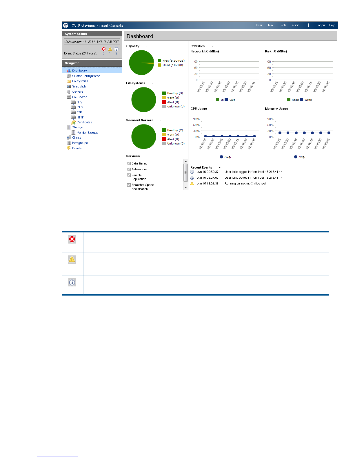
System Status
The System Status section lists the number of cluster events that have occurred in the last 24 hours.
There are three types of events:
Alerts. Disruptive events that can result in loss of access to file system data. Examples are a segment that is
unavailable or a server that cannot be accessed.
Warnings. Potentially disruptive conditions where file system access is not lost, but if the situation is not
addressed, it can escalate to an alert condition. Examples are a very high server CPU utilization level or a
quota limit close to the maximum.
Information. Normal events that change the cluster. Examples are mounting a file system or creating a
segment.
Cluster Overview
The Cluster Overview provides the following information:
Capacity
The amount of cluster storage space that is currently free or in use.
Filesystems
The current health status of the file systems in the cluster. The overview reports the number of
file systems in each state (healthy, experiencing a warning, experiencing an alert, or unknown).
Segment Servers
The current health status of the file serving nodes in the cluster. The overview reports the number
of nodes in each state (healthy, experiencing a warning, experiencing an alert, or unknown).
Management interfaces 17
Page 18

Services
Whether the specified file system services are currently running:
One or more tasks are
running.
No tasks are running.
Statistics
Historical performance graphs for the following items:
• Network I/O (MB/s)
• Disk I/O (MB/s)
• CPU usage (%)
• Memory usage (%)
On each graph, the X-axis represents time and the Y-axis represents performance.
Use the Statistics menu to select the servers to monitor (up to two), to change the maximum
value for the Y-axis, and to show or hide resource usage distribution for CPU and memory.
Recent Events
The most recent cluster events. Use the Recent Events menu to select the type of events to display.
You can also access certain menu items directly from the Cluster Overview. Mouse over the
Capacity, Filesystems or Segment Server indicators to see the available options.
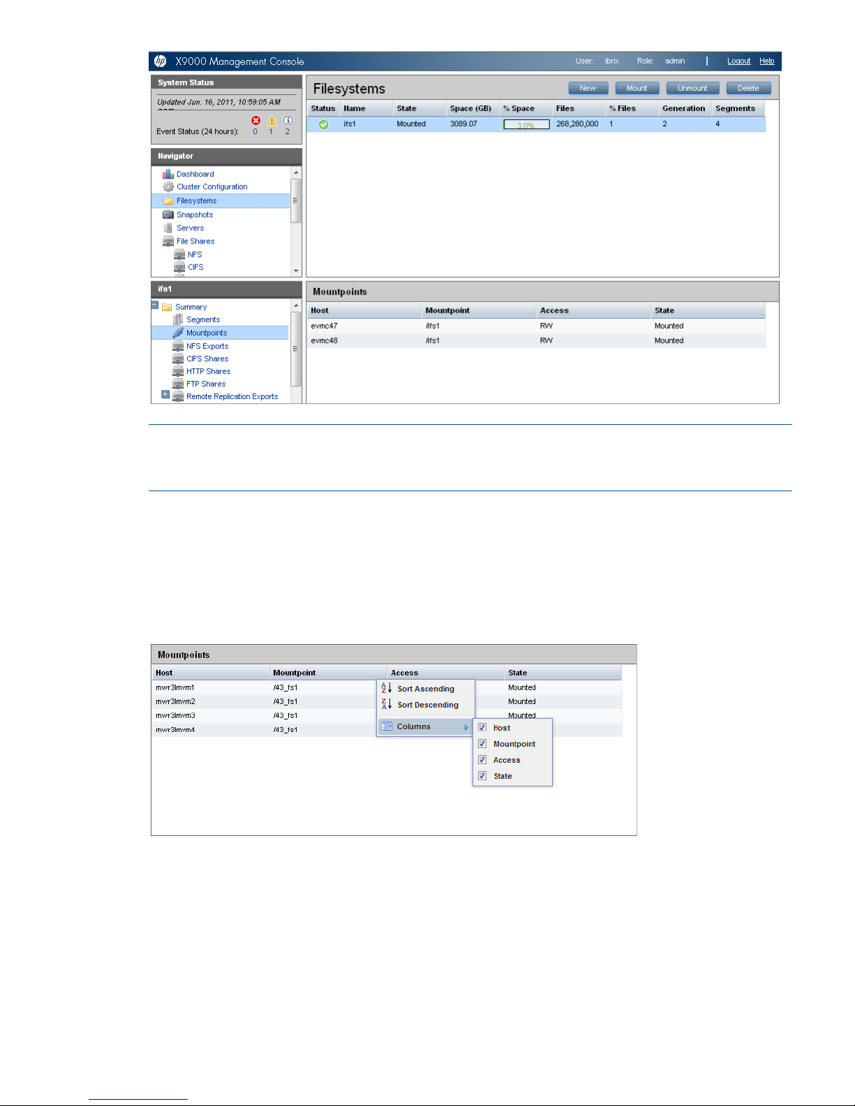
Navigator
The Navigator appears on the left side of the window and displays the cluster hierarchy. You can
use the Navigator to drill down in the cluster configuration to add, view, or change cluster objects
such as file systems or storage, and to initiate or view tasks such as snapshots or replication. When
you select an object, a details page shows a summary for that object. The lower Navigator allows
you to view details for the selected object, or to initiate a task. In the following example, we selected
Filesystems in the upper Navigator and Mountpoints in the lower Navigator to see details about
the mounts for file system ifs1.
18 Getting started
Page 19
NOTE: When you perform an operation on the GUI, a spinning finger is displayed until the
operation is complete. However, if you use Windows Remote Desktop to access the GUI, the
spinning finger is not displayed.
Customizing the GUI
For most tables in the GUI, you can specify the columns that you want to display and the sort order
of each column. When this feature is available, mousing over a column causes the label to change
color and a pointer to appear. Click the pointer to see the available options. In the following
example, you can sort the contents of the Mountpoint column in ascending or descending order,
and you can select the columns that you want to appear in the display.
Adding user accounts for GUI access
X9000 software supports administrative and user roles. When users log in under the administrative
role, they can configure the cluster and initiate operations such as remote replication or snapshots.
When users log in under the user role, they can view the cluster configuration and status, but cannot
make configuration changes or initiate operations. The default administrative user name is ibrix.
The default regular username is ibrixuser.
Usernames for the administrative and user roles are defined in the /etc/group file. Administrative
users are specified in the ibrix-admin group, and regular users are specified in the ibrix-user
Management interfaces 19
Page 20

group. These groups are created when X9000 software is installed. The following entries in the
/etc/group file show the default users in these groups:
ibrix-admin:x:501:root,ibrix
ibrix-user:x:502:ibrix,ibrixUser,ibrixuser
You can add other users to these groups as needed, using Linux procedures. For example:
adduser -G ibrix-<groupname> <username>
When using the adduser command, be sure to include the -G option.
Using the CLI
The administrative commands described in this guide must be executed on the Fusion Manager
host and require root privileges. The commands are located in $IBRIXHOME⁄bin. For complete
information about the commands, see the HP IBRIX X9000 Network Storage System CLI Reference
Guide.
When using ssh to access the machine hosting the Fusion Manager, specify the IP address of the
Fusion Manager user VIF.
Starting the array management software
Depending on the array type, you can launch the array management software from the GUI. In
the Navigator, select Vendor Storage, select your array from the Vendor Storage page, and click
Launch Storage Management.
X9000 client interfaces
X9000 clients can access the Fusion Manager as follows:
• Linux clients. Use Linux client commands for tasks such as mounting or unmounting file systems
and displaying statistics. See the HP IBRIX X9000 Network Storage System CLI Reference
Guide for details about these commands.
• Windows clients. Use the Windows client GUI for tasks such as mounting or unmounting file
systems and registering Windows clients.
Using the Windows X9000 client GUI
The Windows X9000 client GUI is the client interface to the Fusion Manager. To open the GUI,
double-click the desktop icon or select the IBRIX Client program from the Start menu on the client.
The client program contains tabs organized by function.
NOTE: The Windows X9000 client GUI can be started only by users with Administrative privileges.
• Status. Shows the client’s Fusion Manager registration status and mounted file systems, and
provides access to the IAD log for troubleshooting.
• Registration. Registers the client with the Fusion Manager, as described in the HP IBRIX X9000
Network Storage System Installation Guide.
• Mount. Mounts a file system. Select the Cluster Name from the list (the cluster name is the
Fusion Manager name), enter the name of the file system to mount, select a drive, and then
click Mount. (If you are using Remote Desktop to access the client and the drive letter does
not appear, log out and log in again.)
• Umount. Unmounts a file system.
• Tune Host. Tunable parameters include the NIC to prefer (the client uses the cluster interface
by default unless a different network interface is preferred for it), the communications protocol
(UDP or TCP), and the number of server threads to use.
• Active Directory Settings. Displays current Active Directory settings.
20 Getting started
Page 21

For more information, see the client GUI online help.
X9000 software manpages
X9000 software provides manpages for most of its commands. To view the manpages, set the
MANPATH variable to include the path to the manpages and then export it. The manpages are in
the $IBRIXHOME/man directory. For example, if $IBRIXHOME is /usr/local/ibrix (the
default), set the MANPATH variable as follows and then export the variable:
MANPATH=$MANPATH:/usr/local/ibrix/man
Changing passwords
IMPORTANT: The hpspAdmin user account is added during the IBRIX software installation and
is used internally. Do not remove this account or change its password.
You can change the following passwords on your system:
• Hardware passwords. See the documentation for the specific hardware for more information.
• Root password. Use the passwd(8) command on each server.
• X9000 software user password. This password is created during installation and is used to
log in to the GUI. The default is ibrix. You can change the password using the Linux passwd
command.
# passwd ibrix
You will be prompted to enter the new password.
Configuring ports for a firewall
IMPORTANT: To avoid unintended consequences, HP recommends that you configure the firewall
during scheduled maintenance times.
When configuring a firewall, you should be aware of the following:
• SELinux should be disabled.
• By default, NFS uses random port numbers for operations such as mounting and locking.
These ports must be fixed so that they can be listed as exceptions in a firewall configuration
file. For example, you will need to lock specific ports for rpc.statd, rpc.lockd,
rpc.mountd, and rpc.quotad.
• It is best to allow all ICMP types on all networks; however, you can limit ICMP to types 0, 3,
8, and 11 if necessary.
Be sure to open the ports listed in the following table.
DescriptionPort
SSH22/tcp
SSH for Onboard Administrator (OA); only for X9720/X9730 blades9022/tcp
NTP123/tcp, 123/upd
Multicast DNS, 224.0.0.2515353/udp
netperf tool12865/tcp
Fusion Manager to file serving nodes80/tcp
443/tcp
Fusion Manager and X9000 file system5432/tcp
X9000 software manpages 21
Page 22

DescriptionPort
8008/tcp
9002/tcp
9005/tcp
9008/tcp
9009/tcp
9200/tcp
Between file serving nodes and NFS clients (user network)
NFS
2049/tcp, 2049/udp
111/tcp, 111/udp
RPC
875/tcp, 875/udp
quota
32803/tcp
lockmanager
32769/udp
lockmanager
892/tcp, 892/udp
mount daemon
662/tcp, 662/udp
stat
2020/tcp, 2020/udp
stat outgoing
4000:4003/tcp
reserved for use by a custom application (CMU) and can be disabled if not used
Between file serving nodes and CIFS clients (user network)137/udp
138/udp
139/tcp
445/tcp
Between file serving nodes and X9000 clients (user network)9000:9002/tcp
9000:9200/udp
Between file serving nodes and FTP clients (user network)20/tcp, 20/udp
21/tcp, 21/udp
Between GUI and clients that need to access the GUI7777/tcp
8080/tcp
Dataprotector5555/tcp, 5555/udp
Internet Printing Protocol (IPP)631/tcp, 631/udp
ICAP1344/tcp, 1344/udp
Configuring NTP servers
When the cluster is initially set up, primary and secondary NTP servers are configured to provide
time synchronization with an external time source. The list of NTP servers is stored in the Fusion
Manager configuration. The active Fusion Manager node synchronizes its time with the external
source. The other file serving nodes synchronize their time with the active Fusion Manager node.
In the absence of an external time source, the local hardware clock on the agile Fusion Manager
node is used as the time source. This configuration method ensures that the time is synchronized
on all cluster nodes, even in the absence of an external time source.
On X9000 clients, the time is not synchronized with the cluster nodes. You will need to configure
NTP servers on X9000 clients.
List the currently configured NTP servers:
ibrix_clusterconfig -i -N
Specify a new list of NTP servers:
22 Getting started
Page 23

ibrix_clusterconfig -c -N SERVER1[,...,SERVERn]
Configuring HP Insight Remote Support on X9000 systems
IMPORTANT: In the X9000 software 6.1 release, the default port for the X9000 SNMP agent
changed from 5061 to 161. This port number cannot be changed.
Prerequisites
The required components for supporting X9000 systems are preinstalled on the file serving nodes.
You must install HP Insight Remote Support on a separate Windows system termed the Central
Management Server (CMS):
• HP Insight Manager (HP SIM). This software manages HP systems and is the easiest and least
expensive way to maximize system uptime and health.
• Insight Remote Support Advanced (IRSA). This version is integrated with HP Systems Insight
Manager (SIM). It provides comprehensive remote monitoring, notification/advisories, dispatch,
and proactive service support. IRSA and HP SIM together are referred to as the CMS.
The following versions of the software are supported.
• HP SIM 6.3 and IRSA 5.6
• HP SIM 7.1 and IRSA 5.7
IMPORTANT: Insight Remote Support Standard (IRSS ) is not supported with X9000 software 6.1
and later.
For product descriptions and information about downloading the software, see the HP Insight
Remote Support Software web page:
http://www.hp.com/go/insightremotesupport
For information about HP SIM:
http://www.hp.com/products/systeminsightmanager
For IRSA documentation:
http://www.hp.com/go/insightremoteadvanced-docs
Limitations
Note the following:
• For X9000 systems, the HP Insight Remote Support implementation is limited to hardware
events.
• The X9720 CX storage device is not supported for HP Insight Remote Support.
Configuring the X9000 cluster for Insight Remote Support
To enable X9720/X9730 systems for remote support, first enable Phone Home on the cluster, and
then configure Phone Home settings. All nodes in the cluster should be up when you perform this
step.
Enabling Phone Home on the cluster
To enable Phone Home, run the following command:
ibrix_phonehome -F
Configuring HP Insight Remote Support on X9000 systems 23
Page 24
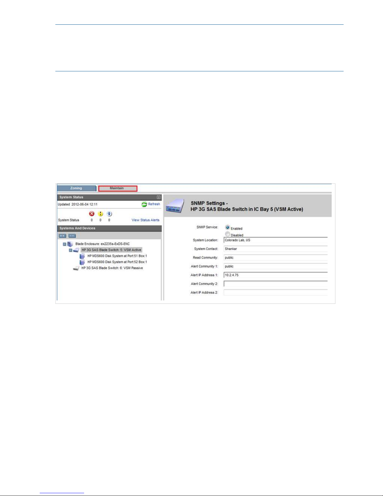
NOTE: Enabling Phone Home removes any previous X9000 snmp configuration details and
populates the snmp configuration with Phone Home configuration details. When Phone Home is
enabled, you cannot use ibrix_snmpagent to edit or change the X9000 snmp agent
configuration. However, you can use ibrix_snmptrap to add trapsink IPs and you can use
ibrix_event to associate events to the trapsink IPs.
Registering Onboard Administrator
The Onboard Administrator is registered automatically.
Configuring the Virtual SAS Manager
On X9730 systems, the SNMP service is disabled by default on the SAS switches. To enable the
SNMP service manually and provide the trapsink IP on all SAS switches, complete these steps:
1. Open the Virtual SAS Manager from the OA. Select OA IP > Interconnet Bays > SAS Switch
> Management Console.
2. On the Virtual SAS Manager, open the Maintain tab, click SAS Blade Switch, and select SNMP
Settings. On the dialog box, enable the SNMP service and supply the information needed for
alerts.
Configuring the Virtual Connect Manager
To configure the Virtual Connect Manager on an X9720/X9730 system, complete the following
steps:
1. From the Onboard Administrator, select OA IP > Interconnet Bays > HP VC Flex-10 >
Management Console.
2. On the HP Virtual Connect Manager, open the SNMP Configuration tab.
3. Configure the SNMP Trap Destination:
• Enter the Destination Name and IP Address (the CMS IP).
• Select SNMPv1 as the SNMP Trap Format.
• Specify public as the Community String.
4. Select all trap categories, VCM traps, and trap severities.
24 Getting started
Page 25
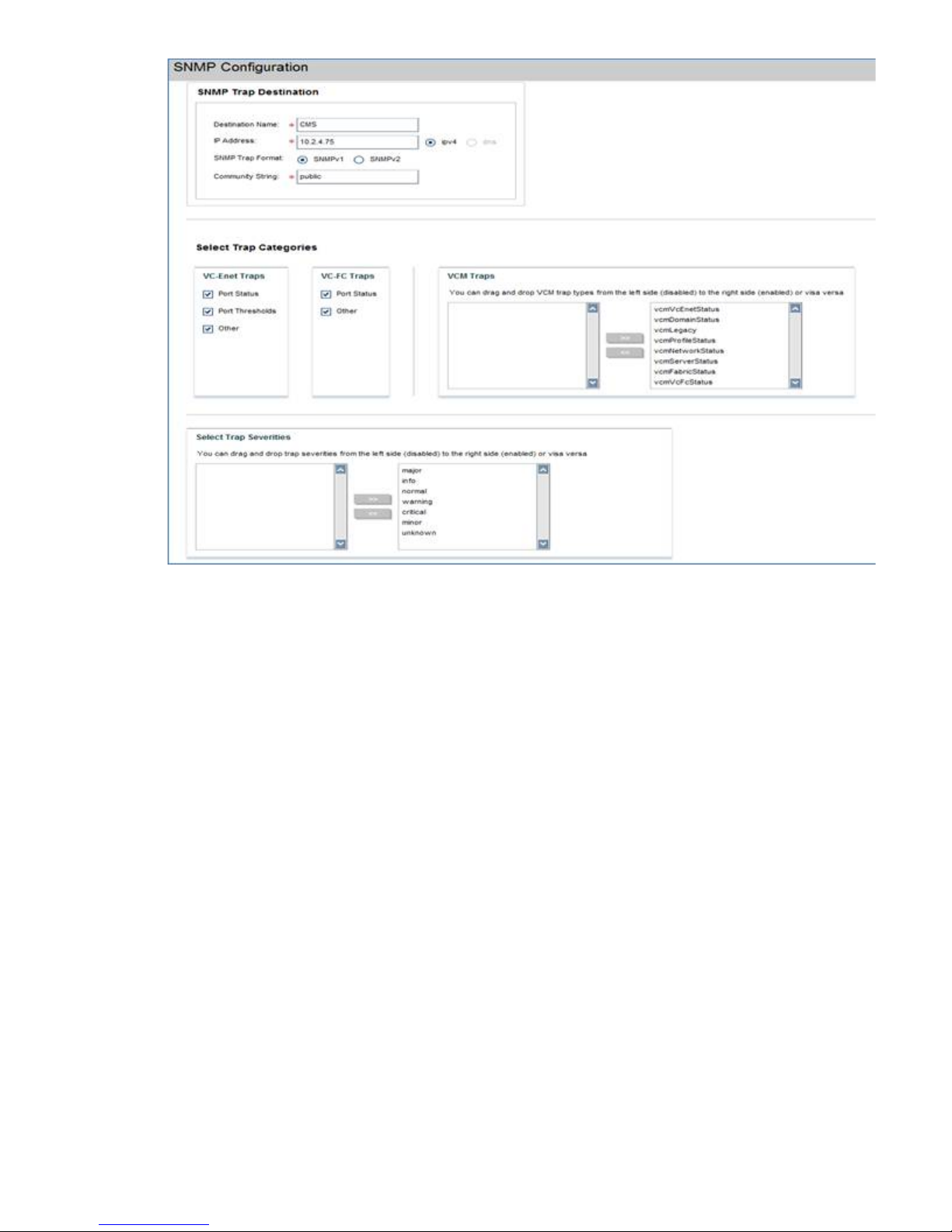
Configuring Phone Home settings
To configure Phone Home on the GUI, select Cluster Configuration in the upper Navigator and
then select Phone Home in the lower Navigator. The Phone Home Setup panel shows the current
configuration.
Configuring HP Insight Remote Support on X9000 systems 25
Page 26
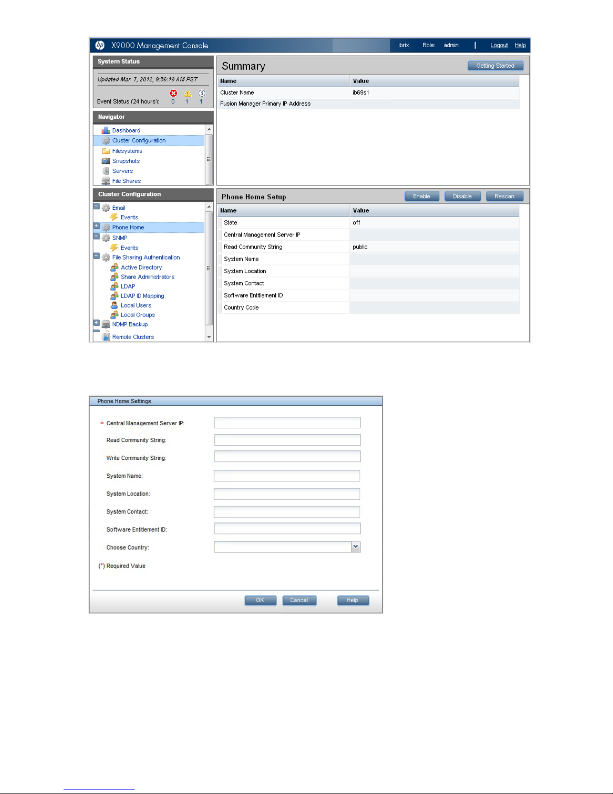
Click Enable to configure the settings on the Phone Home Settings dialog box. Skip the Software
Entitlement ID field; it is not currently used.
The time required to enable Phone Home depends on the number of devices in the cluster, with
larger clusters requiring more time.
To configure Phone Home settings from the CLI, use the following command:
ibrix_phonehome -c -i <IP Address of the Central Management Server> [-z
Software Entitlement Id] [-r Read Community] [-w Write Community] [-t
System Contact] [-n System Name] [-o System Location]
For example:
26 Getting started
Page 27
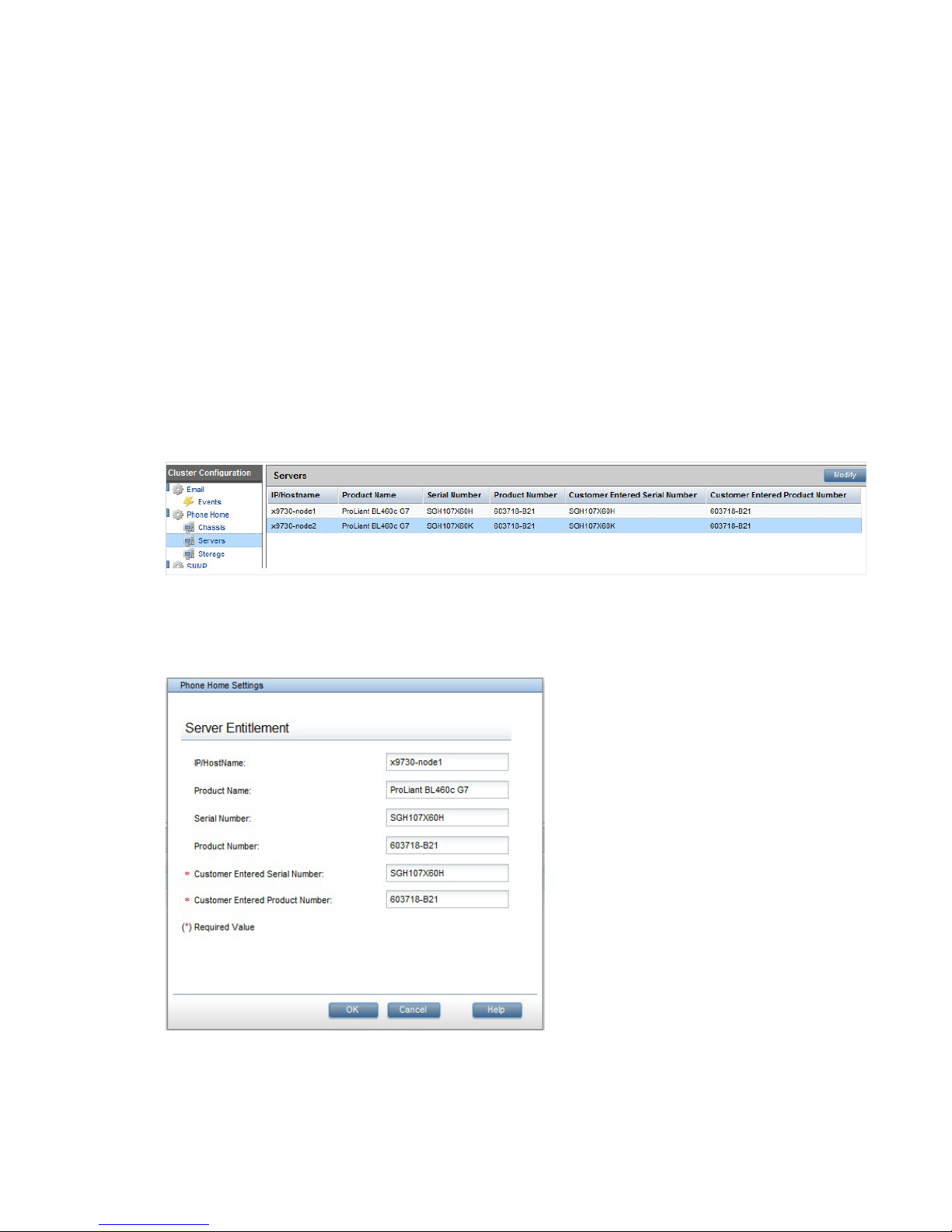
ibrix_phonehome -c -i 99.2.4.75 -P US -r public -w private -t Admin -n
SYS01.US -o Colorado
Next, configure Insight Remote Support for the version of HP SIM you are using:
• HP SIM 7.1 and IRS 5.7. See “Configuring Insight Remote Support for HP SIM 7.1 and IRS
5.7” (page 27).
• HP SIM 6.3 and IRS 5.6. See “Configuring Insight Remote Support for HP SIM 6.3 and IRS
5.6” (page 29).
Configuring Insight Remote Support for HP SIM 7.1 and IRS 5.7
To configure Insight Remote Support, complete these steps:
1. Configure Entitlements for the servers and chassis in your system.
2. Discover devices on HP SIM.
Configuring Entitlements for servers and chassis
Expand Phone Home in the lower Navigator. When you select Chassis or Servers, the GUI displays
the current Entitlements for that type of device. The following example shows Entitlements for the
servers in the cluster.
To configure Entitlements, select a device and click Modify to open the dialog box for that type of
device. The following example shows the Server Entitlement dialog box. The customer-entered
serial number and product number are used for warranty checks at HP Support.
Use the following commands to entitle devices from the CLI. The commands must be run for each
device present in the cluster.
Entitle a server:
ibrix_phonehome -e -h <Host Name> -b <Customer Entered Serial Number>
-g <Customer Entered Product Number>
Configuring HP Insight Remote Support on X9000 systems 27
Page 28
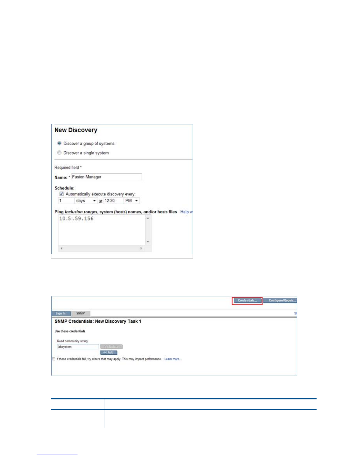
Enter the Host Name parameter exactly as it is listed by the ibrix_fm -l command.
Entitle a chassis:
ibrix_phonehome -e -C <OA IP Address of the Chassis> -b <Customer Entered
Serial Number> -g <Customer Entered Product Number>
NOTE: The Phone Home > Storage selection on the GUI does not apply to X9720/X9730 systems.
Discovering devices on HP SIM
HP Systems Insight Manager (SIM) uses the SNMP protocol to discover and identify X9000 systems
automatically. On HP SIM, open Options > Discovery > New. Select Discover a group of systems,
and then enter the discovery name and the Fusion Manager IP address on the New Discovery
dialog box.
Enter the read community string on the Credentials > SMTP tab. This string should match the Phone
Home read community string. If the strings are not identical, the Fusion Manager IP might be
discovered as “Unknown.”
Devices are discovered as described in the following table.
Discovered asDevice
Fusion Manager
nl
System Type:
nl
Fusion Manager IP
X9000
nl
System Subtype:
nl
28 Getting started
Page 29
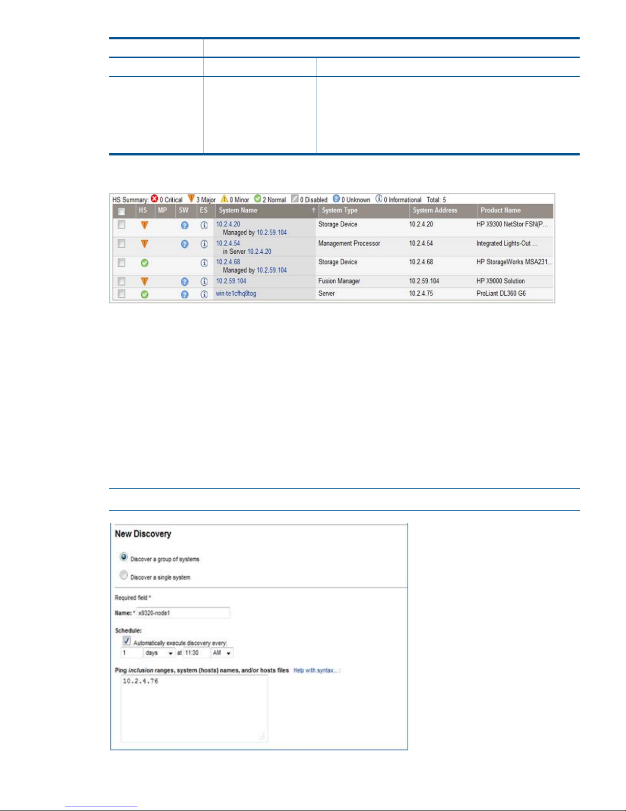
Discovered asDevice
Product Model: HP X9000 Solution
Storage Device
nl
System Type:
nl
File serving nodes
X9000, Storage, HP ProLiant
nl
System Subtype:
nl
HP X9720 NetStor FSN(ProLiant BL460 G6)
nl
Product Model:
nl
HP X9720 NetStor FSN(ProLiant BL460 G6)
nl
HP X9730 NetStor FSN(ProLiant BL460 G7)
nl
HP X9730 NetStor FSN(ProLiant BL460 G7)
The following example shows discovered devices on HP SIM 7.1.
File serving nodes and the OA IP are associated with the Fusion Manager IP address. In HP SIM,
select Fusion Manager and open the Systems tab. Then select Associations to view the devices.
You can view all X9000 devices under Systems by Type > Storage System > Scalable Storage
Solutions > All X9000 Systems
Configuring Insight Remote Support for HP SIM 6.3 and IRS 5.6
Discovering devices in HP SIM
HP Systems Insight Manager (SIM) uses the SNMP protocol to discover and identify X9000 systems
automatically. On HP SIM, open Options > Discovery > New, and then select Discover a group of
systems. On the Edit Discovery dialog box, enter the discovery name and the IP addresses of the
devices to be monitored. For more information, see the HP Sim 6.3 documentation.
NOTE: Each device in the cluster should be discovered separately.
Configuring HP Insight Remote Support on X9000 systems 29
Page 30
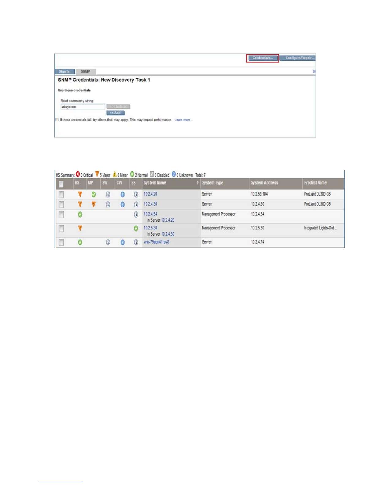
Enter the read community string on the Credentials > SMTP tab. This string should match the Phone
Home read community string. If the strings are not identical, the device will be discovered as
“Unknown.”
The following example shows discovered devices on HP SIM 6.3. File serving nodes are discovered
as ProLiant server.
Configuring device Entitlements
Configure the CMS software to enable remote support for X9000 systems. For more information,
see "Using the Remote Support Setting Tab to Update Your Client and CMS Information” and
“Adding Individual Managed Systems” in the HP Insight Remote Support Advanced A.05.50
Operations Guide.
Enter the following custom field settings in HP SIM:
• Custom field settings for X9720/X9730 Onboard Administrator
The Onboard Administrator (OA) is discovered with OA IP addresses. When the OA is
discovered, edit the system properties on the HP Systems Insight Manager. Locate the Entitlement
Information section of the Contract and Warranty Information page and update the following:
◦ Enter the X9000 enclosure product number as the Customer-Entered product number
◦ Enter X9000 as the Custom Delivery ID
◦ Select the System Country Code
◦ Enter the appropriate Customer Contact and Site Information details
• Contract and Warranty Information
Under Entitlement Information, specify the Customer-Entered serial number, Customer-Entered
product number, System Country code, and Custom Delivery ID.
30 Getting started
Page 31

Verifying device entitlements
To verify the entitlement information in HP SIM, complete the following steps:
1. Go to Remote Support Configuration and Services and select the Entitlement tab.
2. Check the devices discovered.
NOTE: If the system discovered on HP SIM does not appear on the Entitlement tab, click
Synchronize RSE.
3. Select Entitle Checked from the Action List.
4. Click Run Action.
5. When the entitlement check is complete, click Refresh.
NOTE: If the system discovered on HP SIM does not appear on the Entitlement tab, click
Synchronize RSE.
The devices you entitled should be displayed as green in the ENT column on the Remote Support
System List dialog box.
If a device is red, verify that the customer-entered serial number and part number are correct and
then rediscover the devices.
Configuring HP Insight Remote Support on X9000 systems 31
Page 32

Testing the Insight Remote Support configuration
To determine whether the traps are working properly, send a generic test trap with the following
command:
snmptrap -v1 -c public <CMS IP> .1.3.6.1.4.1.232 <Managed System IP> 6
11003 1234 .1.3.6.1.2.1.1.5.0 s test .1.3.6.1.4.1.232.11.2.11.1.0 i 0
.1.3.6.1.4.1.232.11.2.8.1.0 s "X9000 remote support testing"
For example, if the CMS IP address is 99.2.2.2 and the X9000 node is 99.2.2.10, enter the
following:
snmptrap -v1 -c public 99.2.2.2 .1.3.6.1.4.1.232 99.2.2.10 6 11003 1234
.1.3.6.1.2.1.1.5.0 s test .1.3.6.1.4.1.232.11.2.11.1.0 i 0
.1.3.6.1.4.1.232.11.2.8.1.0 s "X9000 remote support testing"
Updating the Phone Home configuration
The Phone Home configuration should be synchronized after you add or remove devices in the
cluster. The operation enables Phone Home on newly added devices (servers, storage, and chassis)
and removes details for devices that are no longer in the cluster. On the GUI, select Cluster
Configuration in the upper Navigator, select Phone Home in the lower Navigator, and click Rescan
on the Phone Home Setup panel.
On the CLI, run the following command:
ibrix_phonehome –s
Disabling Phone Home
When Phone Home is disabled, all Phone Home information is removed from the cluster and
hardware and software are no longer monitored. To disable Phone Home on the GUI, click Disable
on the Phone Home Setup panel. On the CLI, run the following command:
ibrix_phonehome -d
Troubleshooting Insight Remote Support
Devices are not discovered on HP SIM
Verify that cluster networks and devices can access the CMS. Devices will not be discovered
properly if they cannot access the CMS.
The maximum number of SNMP trap hosts has already been configured
If this error is reported, the maximum number of trapsink IP addresses have already been configured.
For OA devices, the maximum number of trapsink IP addresses is 8. Manually remove a trapsink
IP address from the device and then rerun the Phone Home configuration to allow Phone Home to
add the CMS IP address as a trapsink IP address.
A cluster node was not configured in Phone Home
If a cluster node was down during the Phone Home configuration, the log file will include the
following message:
SEVERE: Sent event server.status.down: Server <server name> down
When the node is up, rescan Phone Home to add the node to the configuration. See “Updating
the Phone Home configuration” (page 32).
Fusion Manager IP is discovered as “Unknown”
Verify that the read community string entered in HP SIM matches the Phone Home read community
string.
Also run snmpwalk on the VIF IP and verify the information:
32 Getting started
Page 33

# snmpwalk -v 1 -c <read community string> <FM VIF IP> .1.3.6.1.4.1.18997
Critical failures occur when discovering X9720 OA
The 3GB SAS switches have internal IPs in the range 169.x.x.x, which cannot be reached from
HP SIM. These switches will not be monitored; however, other OA components are monitored.
Discovered device is reported as unknown on CMS
Run the following command on the file serving node to determine whether the Insight Remote
Support services are running:
# service snmpd status
# service hpsmhd status
# service hp-snmp-agents status
If the services are not running, start them:
# service snmpd start
# service hpsmhd start
# service hp-snmp-agents start
Alerts are not reaching the CMS
If nodes are configured and the system is discovered properly but alerts are not reaching the CMS,
verify that a trapif entry exists in the cma.conf configuration file on the file serving nodes.
Device Entitlement tab does not show GREEN
If the Entitlement tab does not show GREEN, verify the Customer-Entered serial number and part
number or the device.
SIM Discovery
On SIM discovery, use the option Discover a Group of Systems for any device discovery.
Configuring HP Insight Remote Support on X9000 systems 33
Page 34

3 Configuring virtual interfaces for client access
X9000 Software uses a cluster network interface to carry Fusion Manager traffic and traffic between
file serving nodes. This network is configured as bond0 when the cluster is installed. For clusters
with an agile Fusion Manager configuration, a virtual interface is also created for the cluster network
interface to provide failover support for the console.
Although the cluster network interface can carry traffic between file serving nodes and clients, HP
recommends that you configure one or more user network interfaces for this purpose.
To provide high availability for a user network, you should configure a bonded virtual interface
(VIF) for the network and then set up failover for the VIF. This method prevents interruptions to client
traffic. If necessary, the file serving node hosting the VIF can fail over to its standby backup node,
and clients can continue to access the file system through the backup node.
Network and VIF guidelines
To provide high availability, the user interfaces used for client access should be configured as
bonded virtual interfaces (VIFs). Note the following:
• Nodes needing to communicate for file system coverage or for failover must be on the same
network interface. Also, nodes set up as a failover pair must be connected to the same network
interface.
• Use a Gigabit Ethernet port (or faster) for user networks.
• NFS, CIFS, FTP, and HTTP clients can use the same user VIF. The servers providing the VIF
should be configured in backup pairs, and the NICs on those servers should also be configured
for failover.
• For Linux and Windows X9000 clients, the servers hosting the VIF should be configured in
backup pairs. However, X9000 clients do not support backup NICs. Instead, X9000 clients
should connect to the parent bond of the user VIF or to a different VIF.
Creating a bonded VIF
NOTE: The examples in this chapter use the unified network and create a bonded VIF on bond0.
If your cluster uses a different network layout, create the bonded VIF on a user network bond such
as bond1.
Use the following procedure to create a bonded VIF (bond1:1 in this example):
1. If high availability (automated failover) is configured on the servers, disable it. Run the following
command on the Fusion Manager:
# ibrix_server –m -U
2. Identify the bond0:1 VIF:
# ibrix_nic –a -n bond0:1 –h node1,node2,node3,node4
3. Assign an IP address to the bond1:1 VIFs on each node. In the command, -I specifies the
IP address, -M specifies the netmask, and -B specifies the broadcast address:
# ibrix_nic –c –n bond0:1 –h node1 –I 16.123.200.201 –M 255.255.255.0 -B 16.123.200.255
# ibrix_nic –c –n bond0:1 –h node2 –I 16.123.200.202 –M 255.255.255.0 -B 16.123.200.255
# ibrix_nic –c –n bond0:1 –h node3 –I 16.123.200.203 –M 255.255.255.0 -B 16.123.200.255
# ibrix_nic –c –n bond0:1 –h node4 –I 16.123.200.204 –M 255.255.255.0 -B 16.123.200.255
Configuring standby backup nodes
The servers in the cluster are configured in backup pairs. If this step was not done when your cluster
was installed, assign standby backup nodes for the bond0:1 interface. For example, node1 is
the backup for node2, and node2 is the backup for node1.
34 Configuring virtual interfaces for client access
Page 35

1. Add the VIF:
# ibrix_nic –a -n bond0:2 –h node1,node2,node3,node4
2. Set up a standby server for each VIF:
# ibrix_nic –b –H node1/bond0:1,node2/bond0:2
# ibrix_nic –b –H node2/bond0:1,node1/bond0:2
# ibrix_nic –b –H node3/bond0:1,node4/bond0:2
# ibrix_nic –b –H node4/bond0:1,node3/bond0:2
Configuring NIC failover
NIC monitoring should be configured on VIFs that will be used by NFS, CIFS, FTP, or HTTP.
IMPORTANT: When configuring NIC monitoring, use the same backup pairs that you used when
configuring standby servers.
For example:
# ibric_nic –m -h node1 -A node2/bond0:1
# ibric_nic –m -h node2 -A node1/bond0:1
# ibric_nic –m -h node3 -A node4/bond0:1
# ibric_nic –m -h node4 -A node3/bond0:1
Configuring automated failover
To enable automated failover for your file serving nodes, execute the following command:
ibrix_server —m [-h SERVERNAME]
Example configuration
This example uses two nodes, ib50-81 and ib50-82. These nodes are backups for each other,
forming a backup pair.
[root@ib50-80 ~]# ibrix_server -l
Segment Servers
===============
SERVER_NAME BACKUP STATE HA ID GROUP
----------- ------- ------------ --- ------------------------------------ ----ib50-81 ib50-82 Up on 132cf61a-d25b-40f8-890e-e97363ae0d0b servers
ib50-82 ib50-81 Up on 7d258451-4455-484d-bf80-75c94d17121d servers
All VIFs on ib50-81 have backup (standby) VIFs on ib50-82. Similarly, all VIFs on ib50-82
have backup (standby) VIFs on ib50-81. NFS, CIFS, FTP, and HTTP clients can connect to bond0:1
on either host. If necessary, the selected server will fail over to bond0:2 on the opposite host.
X9000 clients could connect to bond1 on either host, as these clients do not support or require
NIC failover. (The following sample output shows only the relevant fields.)
Configuring NIC failover 35
Page 36

Specifying VIFs in the client configuration
When you configure your clients, you may need to specify the VIF that should be used for client
access.
NFS/CIFS. Specify the VIF IP address of the servers (for example, bond0:1) to establish connection.
You can also configure DNS round robin to ensure NFS or CIFS client-to-server distribution. In both
cases, the NFS/CIFS clients will cache the initial IP they used to connect to the respective share,
usually until the next reboot.
FTP. When you add an FTP share on the Add FTP Shares dialog box or with the ibrix_ftpshare
command, specify the VIF as the IP address that clients should use to access the share.
HTTP. When you create a virtual host on the Create Vhost dialog box or with the
ibrix_httpvhost command, specify the VIF as the IP address that clients should use to access
shares associated with the Vhost.
X9000 clients. Use the following command to prefer the appropriate user network. Execute the
command once for each destination host that the client should contact using the specified interface.
ibrix_client -n -h SRCHOST -A DESTNOST/IFNAME
For example:
ibrix_client -n -h client12.mycompany.com -A ib50-81.mycompany.com/bond1
NOTE: Because the backup NIC cannot be used as a preferred network interface for X9000
clients, add one or more user network interfaces to ensure that HA and client communication work
together.
Support for link state monitoring
Do not configure link state monitoring for user network interfaces or VIFs that will be used for CIFS
or NFS. Link state monitoring is supported only for use with iSCSI storage network interfaces, such
as those provided with X9300 Gateway systems.
36 Configuring virtual interfaces for client access
Page 37

4 Configuring failover
This chapter describes how to configure failover for agile management consoles, file serving nodes,
network interfaces, and HBAs.
Agile management consoles
The agile Fusion Manager maintains the cluster configuration and provides graphical and
command-line user interfaces for managing and monitoring the cluster. The agile Fusion Manager
is installed on all file serving nodes when the cluster is installed. The Fusion Manager is active on
one node, and is passive on the other nodes. This is called an agile Fusion Manager configuration.
Agile Fusion Manager modes
An agile Fusion Manager can be in one of the following modes:
• active. In this mode, the Fusion Manager controls console operations. All cluster administration
and configuration commands must be run from the active Fusion Manager.
• passive. In this mode, the Fusion Manager monitors the health of the active Fusion Manager.
If the active Fusion Manager fails, the a passive Fusion Manager is selected to become the
active console.
• nofmfailover. In this mode, the Fusion Manager does not participate in console operations.
Use this mode for operations such as manual failover of the active Fusion Manager, X9000
software upgrades, and server blade replacements.
Changing the mode
Use the following command to move a Fusion Manager to passive or nofmfailover mode:
ibrix_fm -m passive | nofmfailover [-A | -h <FMLIST>]
If the Fusion Manager was previously the active console, X9000 software will select a new active
console. A Fusion Manager currently in active mode can be moved to either passive or nofmfailover
mode. A Fusion Manager in nofmfailover mode can be moved only to passive mode.
With the exception of the local node running the active Fusion Manager, the -A option moves all
instances of the Fusion Manager to the specified mode. The -h option moves the Fusion Manager
instances in <FMLIST> to the specified mode.
Agile Fusion Manager and failover
Using an agile Fusion Manager configuration provides high availability for Fusion Manager
services. If the active Fusion Manager fails, the cluster virtual interface will go down. When the
passive Fusion Manager detects that the cluster virtual interface is down, it will become the active
console. This Fusion Manager rebuilds the cluster virtual interface, starts Fusion Manager services
locally, transitions into active mode, and take over Fusion Manager operation.
Failover of the active Fusion Manager affects the following features:
• User networks. The virtual interface used by clients will also fail over. Users may notice a brief
reconnect while the newly active Fusion Manager takes over management of the virtual
interface.
• GUI. You must reconnect to the Fusion Manager VIF after the failover.
Failing over the Fusion Manager manually
To fail over the active Fusion Manager manually, place the console into nofmfailover mode. Enter
the following command on the node hosting the console:
ibrix_fm -m nofmfailover
Agile management consoles 37
Page 38

The command takes effect immediately.
The failed-over Fusion Manager remains in nofmfailover mode until it is moved to passive mode
using the following command:
ibrix_fm -m passive
NOTE: A Fusion Manager cannot be moved from nofmfailover mode to active mode.
Viewing information about Fusion Managers
To view mode information, use the following command:
ibrix_fm –i
NOTE: If the Fusion Manager was not installed in an agile configuration, the output will report
FusionServer: fusion manager name not set! (active, quorum is not
configured).
When a Fusion Manager is installed, it is registered in the Fusion Manager configuration. To view
a list of all registered management consoles, use the following command:
ibrix_fm –l
Cluster high availability
The High Availability feature keeps your data accessible at all times. Failover protection can be
configured for file serving nodes, network interfaces, individual segments, and HBAs. Through
physical and logical configuration policies, you can set up a flexible and scalable high availability
solution. X9000 clients experience no changes in service and are unaware of the failover events.
Failover modes
High Availability has two failover modes: manual failover (the default) and tautomated failover.
For manual failover, use the ibrix_server command or the GUI to fail over a file serving node
to its standby. The server can be powered down or remain up during the procedure. Manual
failover also includes failover of any network interfaces having defined standbys. You can perform
a manual failover at any time, regardless of whether automated failover is in effect.
Automated failover allows the Fusion Manager to initiate failover when it detects that
standby-protected components have failed. A basic automated failover setup protects all file serving
nodes. A comprehensive setup also includes network interface monitoring to protect user network
interfaces and HBA monitoring to protect access from file serving nodes to storage through an
HBA.
When automated failover is enabled, the Fusion Manager listens for heartbeat messages that the
file serving nodes broadcast at one-minute intervals. The Fusion Manager automatically initiates
failover when it fails to receive five consecutive heartbeats or, if HBA monitoring is enabled, when
a heartbeat message indicates that a monitored HBA or pair of HBAs has failed.
If network interface monitoring is enabled, automated failover occurs when the Fusion Manager
receives a heartbeat message indicating that a monitored network might be down and the Fusion
Manager cannot reach that interface.
If a file serving node fails over, you must fail back the node manually.
What happens during a failover
The following actions occur during automated or manual failover of a file serving node to its
standby:
38 Configuring failover
Page 39

1. The Fusion Manager verifies that the standby is powered on and accessible.
2. The Fusion Manager migrates ownership of the node’s segments to the standby and notifies
all file serving nodes and X9000 clients about the migration. This is a persistent change.
3. If network interface monitoring has been set up, the Fusion Manager activates the standby
user network interface and transfers the IP address of the node’s user network interface to it.
To determine the progress of a failover, view the Status tab on the GUI or execute the
ibrix_server -l command. While the Fusion Manager is migrating segment ownership, the
operational status of the node is Up-InFailover or Down-InFailover, depending on whether the node
was powered up or down when failover was initiated. When failover is complete, the operational
status changes to Up-FailedOver or Down-FailedOver. For more information about operational
states, see “Monitoring the status of file serving nodes” (page 64).
Both automated and manual failovers trigger an event that is reported on the GUI.
Setting up automated failover
The recommended minimum setup for automated failover protection is:
1. Configure file serving nodes in standby pairs.
2. Identify power sources for file serving nodes.
3. Turn on automated failover.
If your cluster includes one or more user network interfaces carrying NFS/CIFS client traffic, HP
recommends that you identify standby network interfaces and set up network interface monitoring.
If your file serving nodes are connected to storage through HBAs, HP recommends that you set up
HBA monitoring.
Configuring standby pairs
File serving nodes are configured in standby pairs, where each server in a pair is the standby for
the other. The following restrictions apply:
• The same file system must be mounted on both the primary server and its standby.
• A server identified as a standby must be able to see all segments that might fail over to it.
• In a SAN environment, a primary server and its standby must use the same storage infrastructure
to access a segment’s physical volumes (for example, a multiported RAID array).
See “Configuring standby pairs” (page 39) for more information.
Identifying power sources
To implement automated failover, perform a forced manual failover, or remotely power a file
serving node up or down, you must set up programmable power sources for the nodes and their
standbys. Using programmable power sources prevents a “split-brain scenario” between a failing
file serving node and its standby, allowing the failing server to be centrally powered down by the
Fusion Manager in the case of automated failover, and manually in the case of a forced manual
failover.
X9000 software works with iLO, IPMI, OpenIPMI, and OpenIPMI2 integrated power sources.
Preliminary configuration
The following configuration steps are required when setting up integrated power sources:
• If you plan to implement automated failover, ensure that the Fusion Manager has LAN access
to the power sources.
• Install the environment and any drivers and utilities, as specified by the vendor documentation.
If you plan to protect access to the power sources, set up the UID and password to be used.
Cluster high availability 39
Page 40

Identifying power sources
All power sources must be identified to the configuration database before they can be used. To
identify an integrated power source, use the following command:
ibrix_powersrc -a -t {ipmi|openipmi|openipmi2|ilo} -h HOSTNAME -I IPADDR -u USERNAME -p PASSWORD
For example, to identify an iLO power source at IP address 192.168.3.170 for node ss01:
ibrix_powersrc -a -t ilo -h ss01 -I 192.168.3.170 -u Administrator -p password
Updating the configuration database with power source changes
If you change the IP address or password for a power source, you must update the configuration
database with the changes. To do this, use the following command. The user name and password
options are needed only for remotely managed power sources. Include the -s option to have the
Fusion Manager skip BMC.
ibrix_powersrc -m [-I IPADDR] [-u USERNAME] [-p PASSWORD] [-s] -h POWERSRCLIST
The following command changes the IP address for power source ps1:
ibrix_powersrc -m -I 192.168.3.153 -h ps1
Dissociating a file serving node from a power source
You can dissociate a file serving node from an integrated power source by dissociating it from
slot 1 (its default association) on the power source. Use the following command:
ibrix_hostpower -d -s POWERSOURCE -h HOSTNAME
Deleting power sources from the configuration database
To conserve storage, delete power sources that are no longer in use from the configuration database.
If you are deleting multiple power sources, use commas to separate them.
ibrix_powersrc -d -h POWERSRCLIST
Turning automated failover on and off
Automated failover is turned off by default. When automated failover is turned on, the Fusion
Manager starts monitoring heartbeat messages from file serving nodes. You can turn automated
failover on and off for all file serving nodes or for selected nodes.
To turn on automated failover, use the following command:
ibrix_server -m [-h SERVERNAME]
To turn off automated failover, include the -U option:
ibrix_server -m -U [-h SERVERNAME]
To turn automated failover on or off for a single file serving node, include the -h SERVERNAME
option.
Manually failing over a file serving node
To set up a cluster for manual failover, first identify standby pairs for the cluster nodes, as described
in “Configuring standby pairs” (page 39).
Manual failover does not require the use of programmable power supplies. However, if you have
installed and identified power supplies for file serving nodes, you can power down a server before
manually failing it over. You can fail over a file serving node manually, even when automated
failover is turned on.
A file serving node can be failed over from the GUI or the CLI.
Using the CLI:
1. Run ibrix_server -f, specifying the node to be failed over in the HOSTNAME option. If
appropriate, include the -p option to power down the node before segments are migrated:
ibrix_server -f [-p] -h HOSTNAME
40 Configuring failover
Page 41

2. Determine whether the failover was successful:
ibrix_server -l
The STATE field indicates the status of the failover. If the field persistently shows Down-InFailover
or Up-InFailover, the failover did not complete; contact HP Support for assistance. For information
about the values that can appear in the STATE field, see “What happens during a failover”
(page 38).
Failing back a file serving node
After automated or manual failover of a file serving node, you must manually fail back the server,
which restores ownership of the failed-over segments and network interfaces to the server. Before
failing back the node, confirm that the primary server can see all of its storage resources and
networks. The segments owned by the primary server will not be accessible if the server cannot
see its storage.
To fail back a file serving node, use the following command, where the HOSTNAME argument
specifies the name of the failed-over node:
ibrix_server -f -U -h HOSTNAME
After failing back the node, determine whether the failback completed fully. If the failback is not
complete, contact HP Support for assistance.
NOTE: A failback might not succeed if the time period between the failover and the failback is
too short, and the primary server has not fully recovered. HP recommends ensuring that both servers
are up and running and then waiting 60 seconds before starting the failback. Use the
ibrix_server -l command to verify that the primary server is up and running. The status should
be Up-FailedOver before performing the failback.
Using network interface monitoring
With network interface monitoring, one file serving node monitors another file serving node over
a designated network interface. If the monitoring server loses contact with its destination server
over the interface, it notifies the Fusion Manager. If the Fusion Manager also cannot contact the
destination server over that interface, it fails over both the destination server and the network
interface to their standbys. Clients that were mounted on the failed-over server do not experience
any service interruption and are unaware that they are now mounting the file system on a different
server.
Unlike X9000 clients, NFS and CIFS clients cannot reroute file requests to a standby if the file
serving node where they are mounted should fail. To ensure continuous client access to files, HP
recommends that you put NFS/CIFS traffic on a user network interface (see “Preferring network
interfaces” (page 87)), and then implement network interface monitoring for it.
Comprehensive protection of NFS/CIFS traffic also involves setting up network interface monitoring
for the cluster interface. Although the Fusion Manager eventually detects interruption of a file serving
node’s connection to the cluster interface and initiates segment failover if automated failover is
turned on, failover occurs much faster if the interruption is detected through network interface
monitoring. (If automated failover is not turned on, you will see file access problems if the cluster
interface fails.) There is no difference in the way that monitoring is set up for the cluster interface
and a user network interface. In both cases, you set up file serving nodes to monitor each other
over the interface.
Sample scenario
The following diagram illustrates a monitoring and failover scenario in which a 1:1 standby
relationship is configured. Each standby pair is also a network interface monitoring pair. When
SS1 loses its connection to the user network interface (eth1), as shown by the red X, SS2 can no
longer contact SS1 (A). SS2 notifies the Fusion Manager, which then tests its own connection with
Cluster high availability 41
Page 42

SS1 over eth1 (B). The Fusion Manager cannot contact SS1 on eth1, and initiates failover of
SS1’s segments (C) and user network interface (D).
Identifying standbys
To protect a network interface, you must identify a standby for it on each file serving node that
connects to the interface. The following restrictions apply when identifying a standby network
interface:
• The standby network interface must be unconfigured and connected to the same switch (network)
as the primary interface.
• The file serving node that supports the standby network interface must have access to the file
system that the clients on that interface will mount.
Virtual interfaces are highly recommended for handling user network interface failovers. If a VIF
user network interface is teamed/bonded, failover occurs only if all teamed network interfaces
fail. Otherwise, traffic switches to the surviving teamed network interfaces.
To identify standbys for a network interface, execute the following command once for each file
serving node. IFNAME1 is the network interface that you want to protect and IFNAME2 is the
standby interface.
ibrix_nic -b -H HOSTNAME1/IFNAME1,HOSTNAME2/IFNAME2
The following command identifies virtual interface eth2:2 on file serving node s2.hp.com as the
standby interface for interface eth2 on file serving node s1.hp.com:
ibrix_nic -b -H s1.hp.com/eth2,s2.hp.com/eth2:2
Setting up a monitor
File serving node failover pairs can be identified as network interface monitors for each other.
Because the monitoring must be declared in both directions, this is a two-pass process for each
failover pair.
To set up a network interface monitor, use the following command:
ibrix_nic -m -h MONHOST -A DESTHOST/IFNAME
For example, to set up file serving node s2.hp.com to monitor file serving node s1.hp.com over
user network interface eth1:
ibrix_nic -m -h s2.hp.com -A s1.hp.com/eth1
To delete network interface monitoring, use the following command:
42 Configuring failover
Page 43

ibrix_nic -m -h MONHOST -D DESTHOST/IFNAME
Deleting standbys
To delete a standby for a network interface, use the following command:
ibrix_nic -b -U HOSTNAME1/IFNAME1
For example, to delete the standby that was assigned to interface eth2 on file serving node
s1.hp.com:
ibrix_nic -b -U s1.hp.com/eth2
Setting up HBA monitoring
You can configure High Availability to initiate automated failover upon detection of a failed HBA.
HBA monitoring can be set up for either dual-port HBAs with built-in standby switching or single-port
HBAs, whether standalone or paired for standby switching via software. The X9000 software does
not play a role in vendor- or software-mediated HBA failover—traffic moves to the remaining
functional port without any Fusion Manager involvement.
HBAs use worldwide names for some parameter values. These are either worldwide node names
(WWNN) or worldwide port names (WWPN). The WWPN is the name an HBA presents when
logging in to a SAN fabric. Worldwide names consist of 16 hexadecimal digits grouped in pairs.
In X9000 software, these are written as dot-separated pairs (for example,
21.00.00.e0.8b.05.05.04).
To set up HBA monitoring, first discover the HBAs, and then perform the procedure that matches
your HBA hardware:
• For single-port HBAs without built-in standby switching: Turn on HBA monitoring for all ports
that you want to monitor for failure (see “Turning HBA monitoring on or off” (page 44)).
• For dual-port HBAs with built-in standby switching and single-port HBAs that have been set
up as standby pairs in a software operation: Identify the standby pairs of ports to the
configuration database (see “Identifying standby-paired HBA ports” (page 44), and then turn
on HBA monitoring for all paired ports (see “Turning HBA monitoring on or off” (page 44)).
If monitoring is turned on for just one port in a standby pair and that port fails, the Fusion
Manager will fail over the server even though the HBA has automatically switched traffic to
the surviving port. When monitoring is turned on for both ports, the Fusion Manager initiates
failover only when both ports in a pair fail.
When both HBA monitoring and automated failover for file serving nodes are configured, the
Fusion Manager will fail over a server in two situations:
• Both ports in a monitored set of standby-paired ports fail. Because all standby pairs were
identified in the configuration database, the Fusion Manager knows that failover is required
only when both ports fail.
• A monitored single-port HBA fails. Because no standby has been identified for the failed port,
the Fusion Manager knows to initiate failover immediately.
Discovering HBAs
You must discover HBAs before you set up HBA monitoring, when you replace an HBA, and when
you add a new HBA to the cluster. Discovery informs the configuration database of a port’s WWPN
only. You must identify ports that are teamed as standby pairs using the following command:
ibrix_hba -a [-h HOSTLIST]
Cluster high availability 43
Page 44

Identifying standby-paired HBA ports
Identifying standby-paired HBA ports to the configuration database allows the Fusion Manager to
apply the following logic when they fail:
• If one port in a pair fails, do nothing. Traffic will automatically switch to the surviving port, as
configured by the HBA vendor or the software.
• If both ports in a pair fail, fail over the server’s segments to the standby server.
Use the following command to identify two HBA ports as a standby pair:
bin/ibrix_hba -b -P WWPN1:WWPN2 -h HOSTNAME
Enter the WWPN as decimal-delimited pairs of hexadecimal digits. The following command
identifies port 20.00.12.34.56.78.9a.bc as the standby for port 42.00.12.34.56.78.9a.bc for
the HBA on file serving node s1.hp.com:
ibrix_hba -b -P 20.00.12.34.56.78.9a.bc:42.00.12.34.56.78.9a.bc -h s1.hp.com
Turning HBA monitoring on or off
If your cluster uses single-port HBAs, turn on monitoring for all of the ports to set up automated
failover in the event of HBA failure. Use the following command:
ibrix_hba -m -h HOSTNAME -p PORT
For example, to turn on HBA monitoring for port 20.00.12.34.56.78.9a.bc on node s1.hp.com:
ibrix_hba -m -h s1.hp.com -p 20.00.12.34.56.78.9a.bc
To turn off HBA monitoring for an HBA port, include the -U option:
ibrix_hba -m -U -h HOSTNAME -p PORT
Deleting standby port pairings
Deleting port pairing information from the configuration database does not remove the standby
pairing of the ports. The standby pairing is either built in by the HBA vendor or implemented by
software.
To delete standby-paired HBA ports from the configuration database, enter the following command:
ibrix_hba -b -U -P WWPN1:WWPN2 -h HOSTNAME
For example, to delete the pairing of ports 20.00.12.34.56.78.9a.bc and
42.00.12.34.56.78.9a.bc on node s1.hp.com:
ibrix_hba -b -U -P 20.00.12.34.56.78.9a.bc:42.00.12.34.56.78.9a.bc
-h s1.hp.com
Deleting HBAs from the configuration database
Before switching an HBA to a different machine, delete the HBA from the configuration database
using the following command:
ibrix_hba -d -h HOSTNAME -w WWNN
Displaying HBA information
Use the following command to view information about the HBAs in the cluster. To view information
for all hosts, omit the -h HOSTLIST argument.
ibrix_hba -l [-h HOSTLIST]
The following table describes the fields in the output.
DescriptionField
Server on which the HBA is installed.Host
This HBA’s WWNN.Node WWN
44 Configuring failover
Page 45

DescriptionField
This HBA’s WWPN.Port WWN
Operational state of the port.Port State
WWPN of the standby port for this port (standby-paired HBAs only).Backup Port WWN
Whether HBA monitoring is enabled for this port.Monitoring
Checking the High Availability configuration
Use the ibrix_haconfig command to determine whether High Availability features have been
configured for specific file serving nodes. The command checks for the following features and
provides either a summary or a detailed report of the results:
• Programmable power source
• Standby server or standby segments
• Cluster and user network interface monitors
• Standby network interface for each user network interface
• HBA port monitoring
• Status of automated failover (on or off)
For each High Availability feature, the summary report returns status for each tested file serving
node and optionally for their standbys:
• Passed. The feature has been configured.
• Warning. The feature has not been configured, but the significance of the finding is not clear.
For example, the absence of discovered HBAs can indicate either that the HBA monitoring
feature was not configured or that HBAs are not physically present on the tested servers.
• Failed. The feature has not been configured.
The detailed report includes an overall result status for all tested file serving nodes and describes
details about the checks performed on each High Availability feature. By default, the report includes
details only about checks that received a Failed or a Warning result. You can expand the report
to include details about checks that received a Passed result.
Viewing a summary report
Use the ibrix_haconfig -l command to see a summary of all file serving nodes. To check
specific file serving nodes, include the -h HOSTLIST argument. To check standbys, include the
-b argument. To view results only for file serving nodes that failed a check, include the -f argument.
ibrix_haconfig -l [-h HOSTLIST] [-f] [-b]
For example, to view a summary report for file serving nodes xs01.hp.com and xs02.hp.com:
ibrix_haconfig -l -h xs01.hp.com,xs02.hp.com
Host HA Configuration Power Sources Backup Servers Auto Failover
Nics Monitored Standby Nics HBAs Monitored
xs01.hp.com FAILED PASSED PASSED PASSED
FAILED PASSED FAILED
xs02.hp.com FAILED PASSED FAILED FAILED
FAILED WARNED WARNED
Viewing a detailed report
Execute the ibrix_haconfig -i command to view the detailed report:
ibrix_haconfig -i [-h HOSTLIST] [-f] [-b] [-s] [-v]
Cluster high availability 45
Page 46

The -h HOSTLIST option lists the nodes to check. To also check standbys, include the -b option.
To view results only for file serving nodes that failed a check, include the -f argument. The -s
option expands the report to include information about the file system and its segments. The -v
option produces detailed information about configuration checks that received a Passed result.
For example, to view a detailed report for file serving node xs01.hp.com:
ibrix_haconfig -i -h xs01.hp.com
--------------- Overall HA Configuration Checker Results --------------FAILED
--------------- Overall Host Results --------------Host HA Configuration Power Sources Backup Servers Auto Failover Nics Monitored
Standby Nics HBAs Monitored
xs01.hp.com FAILED PASSED PASSED PASSED FAILED
PASSED FAILED
--------------- Server xs01.hp.com FAILED Report ---------------
Check Description Result Result Information
================================================ ====== ==================
Power source(s) configured PASSED
Backup server or backups for segments configured PASSED
Automatic server failover configured PASSED
Cluster & User Nics monitored
Cluster nic xs01.hp.com/eth1 monitored FAILED Not monitored
User nics configured with a standby nic PASSED
HBA ports monitored
Hba port 21.01.00.e0.8b.2a.0d.6d monitored FAILED Not monitored
Hba port 21.00.00.e0.8b.0a.0d.6d monitored FAILED Not monitored
46 Configuring failover
Page 47

5 Configuring cluster event notification
Cluster events
There are three categories for cluster events:
Alerts. Disruptive events that can result in loss of access to file system data.
Warnings. Potentially disruptive conditions where file system access is not lost, but if the situation is not
addressed, it can escalate to an alert condition.
Information. Normal events that change the cluster.
The following table lists examples of events included in each category.
NameTrigger PointEvent Type
login.failureUser fails to log into GUIALERT
filesystem.unmountedFile system is unmounted
server.status.downFile serving node is down/restarted
server.unreachableFile serving node terminated unexpectedly
segment.migratedUser migrates segment using GUIWARN
login.successUser successfully logs in to GUIINFO
filesystem.cmdFile system is created
server.deregisteredFile serving node is deleted
nic.addedNIC is added using GUI
nic.removedNIC is removed using GUI
physicalvolume.addedPhysical storage is discovered and added using
management console
physicalvolume.deletedPhysical storage is deleted using management console
You can be notified of cluster events by email or SNMP traps. To view the list of supported events,
use the command ibrix_event –q.
Setting up email notification of cluster events
You can set up event notifications by event type or for one or more specific events. To set up
automatic email notification of cluster events, associate the events with email recipients and then
configure email settings to initiate the notification process.
Associating events and email addresses
You can associate any combination of cluster events with email addresses: all Alert, Warning, or
Info events, all events of one type plus a subset of another type, or a subset of all types.
The notification threshold for Alert events is 90% of capacity. Threshold-triggered notifications are
sent when a monitored system resource exceeds the threshold and are reset when the resource
Cluster events 47
Page 48

utilization dips 10% below the threshold. For example, a notification is sent the first time usage
reaches 90% or more. The next notice is sent only if the usage declines to 80% or less (event is
reset), and subsequently rises again to 90% or above.
To associate all types of events with recipients, omit the -e argument in the following command:
ibrix_event -c [-e ALERT|WARN|INFO|EVENTLIST] -m EMAILLIST
Use the ALERT, WARN, and INFO keywords to make specific type associations or use EVENTLIST
to associate specific events.
The following command associates all types of events to admin@hp.com:
ibrix_event -c -m admin@hp.com
The next command associates all Alert events and two Info events to admin@hp.com:
ibrix_event -c -e ALERT,server.registered,filesystem.space.full
-m admin@hp.com
Configuring email notification settings
To configure email notification settings, specify the SMTP server and header information and turn
the notification process on or off.
ibrix_event -m on|off -s SMTP -f from [-r reply-to] [-t subject]
The server must be able to receive and send email and must recognize the From and Reply-to
addresses. Be sure to specify valid email addresses, especially for the SMTP server. If an address
is not valid, the SMTP server will reject the email.
The following command configures email settings to use the mail.hp.com SMTP server and turns
on notifications:
ibrix_event -m on -s mail.hp.com -f FM@hp.com -r MIS@hp.com -t Cluster1 Notification
NOTE: The state of the email notification process has no effect on the display of cluster events
in the GUI.
Dissociating events and email addresses
To remove the association between events and email addresses, use the following command:
ibrix_event -d [-e ALERT|WARN|INFO|EVENTLIST] -m EMAILLIST
For example, to dissociate event notifications for admin@hp.com:
ibrix_event -d -m admin@hp.com
To turn off all Alert notifications for admin@hp.com:
ibrix_event -d -e ALERT -m admin@hp.com
To turn off the server.registered and filesystem.created notifications for
admin1@hp.com and admin2@hp.com:
ibrix_event -d -e server.registered,filesystem.created -m admin1@hp.com,admin2@hp.com
Testing email addresses
To test an email address with a test message, notifications must be turned on. If the address is
valid, the command signals success and sends an email containing the settings to the recipient. If
the address is not valid, the command returns an address failed exception.
ibrix_event -u -n EMAILADDRESS
Viewing email notification settings
The ibrix_event -L command provides comprehensive information about email settings and
configured notifications.
ibrix_event -L
Email Notification : Enabled
48 Configuring cluster event notification
Page 49

SMTP Server : mail.hp.com
From : FM@hp.com
Reply To : MIS@hp.com
EVENT LEVEL TYPE DESTINATION
------------------------------------- ----- ----- -----------
asyncrep.completed ALERT EMAIL admin@hp.com
asyncrep.failed ALERT EMAIL admin@hp.com
Setting up SNMP notifications
X9000 software supports SNMP (Simple Network Management Protocol) V1 and V2.
Steps for setting up SNMP include:
• Agent configuration (all SNMP versions)
• Trapsink configuration (all SNMP versions)
• Associating event notifications with trapsinks (all SNMP versions)
X9000 software implements an SNMP agent that supports the private X9000 software MIB. The
agent can be polled and can send SNMP traps to configured trapsinks.
Setting up SNMP notifications is similar to setting up email notifications. You must associate events
to trapsinks and configure SNMP settings for each trapsink to enable the agent to send a trap
when an event occurs.
NOTE: When Phone Home is enabled, you cannot edit or change the configuration of the X9000
SNMP agent with the ibrix_snmpagent. However, you can add trapsink IPs with
ibrix_snmtrap and can associate events to the trapsink IP with ibrix_event.
Configuring the SNMP agent
The SNMP agent is created automatically when the Fusion Manager is installed. It is initially
configured as an SNMPv2 agent and is off by default.
Some SNMP parameters and the SNMP default port are the same, regardless of SNMP version.
The default agent port is 161. SYSCONTACT, SYSNAME, and SYSLOCATION are optional MIB-II
agent parameters that have no default values.
NOTE: The default SNMP agent port was changed from 5061 to 161 in the X9000 6.1 release.
This port number cannot be changed.
The -c and -s options are also common to all SNMP versions. The -c option turns the encryption
of community names and passwords on or off. There is no encryption by default. Using the -s
option toggles the agent on and off; it turns the agent on by starting a listener on the SNMP port,
and turns it off by shutting off the listener. The default is off.
The format for a v1 or v2 update command follows:
ibrix_snmpagent -u –v {1|2} [-p PORT] [-r READCOMMUNITY] [-w WRITECOMMUNITY]
[-t SYSCONTACT] [-n SYSNAME] [-o SYSLOCATION] [-c {yes|no}] [-s {on|off}]
The update command for SNMPv1 and v2 uses optional community names. By convention, the
default READCOMMUNITY name used for read-only access and assigned to the agent is public.
No default WRITECOMMUNITY name is set for read-write access (although the name private is
often used).
The following command updates a v2 agent with the write community name private, the agent’s
system name, and that system’s physical location:
ibrix_snmpagent -u –v 2 -w private -n agenthost.domain.com -o DevLab-B3-U6
Setting up SNMP notifications 49
Page 50

Configuring trapsink settings
A trapsink is the host destination where agents send traps, which are asynchronous notifications
sent by the agent to the management station. A trapsink is specified either by name or IP address.
X9000 software supports multiple trapsinks; you can define any number of trapsinks of any SNMP
version, but you can define only one trapsink per host, regardless of the version.
At a minimum, trapsink configuration requires a destination host and SNMP version. All other
parameters are optional and many assume the default value if no value is specified.
The format for creating a v1/v2 trapsink is:
ibrix_snmptrap -c -h HOSTNAME -v {1|2} [-p PORT] [-m COMMUNITY] [-s {on|off}]
If a port is not specified, the command defaults to port 162. If a community is not specified, the
command defaults to the community name public. The -s option toggles agent trap transmission
on and off. The default is on. For example, to create a v2 trapsink with a new community name,
enter:
ibrix_snmptrap -c -h lab13-116 -v 2 -m private
Associating events and trapsinks
Associating events with trapsinks is similar to associating events with email recipients, except that
you specify the host name or IP address of the trapsink instead of an email address.
Use the ibrix_event command to associate SNMP events with trapsinks. The format is:
ibrix_event -c -y SNMP [-e ALERT|INFO|EVENTLIST]
-m TRAPSINK
For example, to associate all Alert events and two Info events with a trapsink at IP address
192.168.2.32, enter:
ibrix_event -c -y SNMP -e ALERT,server.registered,
filesystem.created -m 192.168.2.32
Use the ibrix_event -d command to dissociate events and trapsinks:
ibrix_event -d -y SNMP [-e ALERT|INFO|EVENTLIST] -m TRAPSINK
Deleting elements of the SNMP configuration
All SNMP commands use the same syntax for delete operations, using -d to indicate the object is
to delete. The following command deletes a list of hosts that were trapsinks:
ibrix_snmptrap -d -h lab15-12.domain.com,lab15-13.domain.com,lab15-14.domain.com
There are two restrictions on SNMP object deletions:
• A view cannot be deleted if it is referenced by a group.
• A group cannot be deleted if it is referenced by a user.
Listing SNMP configuration information
All SNMP commands employ the same syntax for list operations, using the -l flag. For example:
ibrix_snmpgroup -l
This command lists the defined group settings for all SNMP groups. Specifying an optional group
name lists the defined settings for that group only.
50 Configuring cluster event notification
Page 51

6 Configuring system backups
Backing up the Fusion Manager configuration
The Fusion Manager configuration is automatically backed up whenever the cluster configuration
changes. The backup occurs on the node hosting the active Fusion Manager. The backup file is
stored at <ibrixhome>/tmp/fmbackup.zip on that node.
The active Fusion Manager notifies the passive Fusion Manager when a new backup file is available.
The passive Fusion Manager then copies the file to <ibrixhome>/tmp/fmbackup.zip on the
node on which it is hosted. If a Fusion Manager is in maintenance mode, it will also be notified
when a new backup file is created, and will retrieve it from the active Fusion Manager.
You can create an additional copy of the backup file at any time. Run the following command,
which creates a fmbackup.zip file in the $IBRIXHOME/log directory:
$IBRIXHOME/bin/db_backup.sh
Once each day, a cron job rotates the $IBRIXHOME/log directory into the $IBRIXHOME/log/
daily subdirectory. The cron job also creates a new backup of the Fusion Manager configuration
in both $IBRIXHOME/tmp and $IBRIXHOME/log.
To force a backup, use the following command:
ibrix_fm -B
IMPORTANT: You will need the backup file to recover from server failures or to undo unwanted
configuration changes. Whenever the cluster configuration changes, be sure to save a copy of
fmbackup.zip in a safe, remote location such as a node on another cluster.
Using NDMP backup applications
The NDMP backup feature can be used to back up and recover entire X9000 software file systems
or portions of a file system. You can use any supported NDMP backup application to perform the
backup and recovery operations. (In NDMP terminology, the backup application is referred to as
a Data Management Application, or DMA.) The DMA is run on a management station separate
from the cluster and communicates with the cluster's file serving nodes over a configurable socket
port.
The NDMP backup feature supports the following:
• NDMP protocol versions 3 and 4
• Two-way NDMP operations
• Three-way NDMP operations between two network storage systems
Each file serving node functions as an NDMP Server and runs the NDMP Server daemon (ndmpd)
process. When you start a backup or restore operation on the DMA, you can specify the node
and tape device to be used for the operation.
Following are considerations for configuring and using the NDMP feature:
• When configuring your system for NDMP operations, attach your tape devices to a SAN and
then verify that the file serving nodes to be used for backup/restore operations can see the
appropriate devices.
• When performing backup operations, take snapshots of your file systems and then back up
the snapshots.
• When directory tree quotas are enabled, an NDMP restore to the original location fails if the
hard quota limit is exceeded. The NDMP restore operation first creates a temporary file and
then restores a file to the temporary file. After this succeeds, the restore operation overwrites
the existing file (if it present in same destination directory) with the temporary file. When the
Backing up the Fusion Manager configuration 51
Page 52

hard quota limit for the directory tree has been exceeded, NDMP cannot create a temporary
file and the restore operation fails.
Configuring NDMP parameters on the cluster
Certain NDMP parameters must be configured to enable communications between the DMA and
the NDMP Servers in the cluster. To configure the parameters on the GUI, select Cluster Configuration
from the Navigator, and then select NDMP Backup. The NDMP Configuration Summary shows the
default values for the parameters. Click Modify to configure the parameters for your cluster on the
Configure NDMP dialog box. See the online help for a description of each field.
To configure NDMP parameters from the CLI, use the following command:
ibrix_ndmpconfig –c [-d IP1,IP2,IP3,...] [-m MINPORT] [-x MAXPORT] [-n LISTENPORT]
[-u USERNAME] [-p PASSWORD] [-e {0=disable,1=enable}] –v {0=10}] [-w BYTES]
[-z NUMSESSIONS]
NDMP process management
Normally all NDMP actions are controlled from the DMA. However, if the DMA cannot resolve a
problem or you suspect that the DMA may have incorrect information about the NDMP environment,
take the following actions from the GUI or CLI:
• Cancel one or more NDMP sessions on a file serving node. Canceling a session stops all
spawned sessions processes and frees their resources if necessary.
• Reset the NDMP server on one or more file serving nodes. This step stops all spawned session
processes, stops the ndmpd and session monitor daemons, frees all resources held by NDMP,
and restarts the daemons.
Viewing or canceling NDMP sessions
To view information about active NDMP sessions, select Cluster Configuration from the Navigator,
and then select NDMP Backup > Active Sessions. For each session, the Active NDMP Sessions
panel lists the host used for the session, the identifier generated by the backup application, the
52 Configuring system backups
Page 53

status of the session (backing up data, restoring data, or idle), the start time, and the IP address
used by the DMA.
To cancel a session, select that session and click Cancel Session. Canceling a session kills all
spawned sessions processes and frees their resources if necessary.
To see similar information for completed sessions, select NDMP Backup > Session History.
View active sessions from the CLI:
ibrix_ndmpsession –l
View completed sessions:
ibrix_ndmpsession –l -s [-t YYYY-MM-DD]
The -t option restricts the history to sessions occurring on or before the specified date.
Cancel sessions on a specific file serving node:
ibrix_ndmpsession –c SESSION1,SESSION2,SESSION3,... –h HOST
Starting, stopping, or restarting an NDMP Server
When a file serving node is booted, the NDMP Server is started automatically. If necessary, you
can use the following command to start, stop, or restart the NDMP Server on one or more file
serving nodes:
ibrix_server –s –t ndmp –c { start | stop | restart} [-h SERVERNAMES]
Viewing or rescanning tape and media changer devices
To view the tape and media changer devices currently configured for backups, select Cluster
Configuration from the Navigator, and then select NDMP Backup > Tape Devices.
If you add a tape or media changer device to the SAN, click Rescan Device to update the list. If
you remove a device and want to delete it from the list, reboot all of the servers to which the device
is attached.
To view tape and media changer devices from the CLI, use the following command:
ibrix_tape –l
Using NDMP backup applications 53
Page 54

To rescan for devices, use the following command:
ibrix_tape –r
NDMP events
An NDMP Server can generate three types of events: INFO, WARN, and ALERT. These events are
displayed on the GUI and can be viewed with the ibrix_event command.
INFO events. Identifies when major NDMP operations start and finish, and also report progress.
For example:
7012:Level 3 backup of /mnt/ibfs7 finished at Sat Nov 7 21:20:58 PST 2009
7013:Total Bytes = 38274665923, Average throughput = 236600391 bytes/sec.
WARN events. Indicates an issue with NDMP access, the environment, or NDMP operations. Be
sure to review these events and take any necessary corrective actions. Following are some examples:
0000:Unauthorized NDMP Client 16.39.40.201 trying to connect
4002:User [joe] md5 mode login failed.
ALERT events. Indicates that an NDMP action has failed. For example:
1102: Cannot start the session_monitor daemon, ndmpd exiting.
7009:Level 6 backup of /mnt/shares/accounts1 failed (writing eod header error).
8001:Restore Failed to read data stream signature.
You can configure the system to send email or SNMP notifications when these types of events
occur.
54 Configuring system backups
Page 55

7 Creating hostgroups for X9000 clients
A hostgroup is a named set of X9000 clients. Hostgroups provide a convenient way to centrally
manage clients. You can put different sets of clients into hostgroups and then perform the following
operations on all members of the group:
• Create and delete mountpoints
• Mount file systems
• Prefer a network interface
• Tune host parameters
• Set allocation policies
Hostgroups are optional. If you do not choose to set them up, you can mount file systems on clients
and tune host settings and allocation policies on an individual level.
How hostgroups work
In the simplest case, the hostgroups functionality allows you to perform an allowed operation on
all X9000 clients by executing a command on the default clients hostgroup with the CLI or the
GUI. The clients hostgroup includes all X9000 clients configured in the cluster.
NOTE: The command intention is stored on the Fusion Manager until the next time the clients
contact the Fusion Manager. (To force this contact, restart X9000 software services on the clients,
reboot the clients, or execute ibrix_lwmount -a or ibrix_lwhost --a.) When contacted,
the Fusion Manager informs the clients about commands that were executed on hostgroups to
which they belong. The clients then use this information to perform the operation.
You can also use hostgroups to perform different operations on different sets of clients. To do this,
create a hostgroup tree that includes the necessary hostgroups. You can then assign the clients
manually, or the Fusion Manager can automatically perform the assignment when you register an
X9000 client, based on the client's cluster subnet. To use automatic assignment, create a domain
rule that specifies the cluster subnet for the hostgroup.
Creating a hostgroup tree
The clients hostgroup is the root element of the hostgroup tree. Each hostgroup in a tree can
have only one parent, but a parent can have multiple children. In a hostgroup tree, operations
performed on lower-level nodes take precedence over operations performed on higher-level nodes.
This means that you can effectively establish global client settings that you can override for specific
clients.
For example, suppose that you want all clients to be able to mount file system ifs1 and to
implement a set of host tunings denoted as Tuning 1, but you want to override these global settings
for certain hostgroups. To do this, mount ifs1 on the clients hostgroup, ifs2 on hostgroup
A, ifs3 on hostgroup C, and ifs4 on hostgroup D, in any order. Then, set Tuning 1 on the
clients hostgroup and Tuning 2 on hostgroup B. The end result is that all clients in hostgroup B
will mount ifs1 and implement Tuning 2. The clients in hostgroup A will mount ifs2 and implement
Tuning 1. The clients in hostgroups C and D respectively, will mount ifs3 and ifs4 and implement
Tuning 1. The following diagram shows an example of these settings in a hostgroup tree.
How hostgroups work 55
Page 56

To create one level of hostgroups beneath the root, simply create the new hostgroups. You do not
need to declare that the root node is the parent. To create lower levels of hostgroups, declare a
parent element for hostgroups. Do not use a host name as a group name.
To create a hostgroup tree using the CLI:
1. Create the first level of the treet:
ibrix_hostgroup -c -g GROUPNAME ]
2. Create all other levels by specifying a parent for the group:
ibrix_hostgroup -c -g GROUPNAME [-p PARENT]
Adding an X9000 client to a hostgroup
You can add an X9000 client to a hostgroup or move a client to a different hostgroup. All clients
belong to the default clients hostgroup.
To add or move a host to a hostgroup, use the ibrix_hostgroup command as follows:
ibrix_hostgroup -m -g GROUP -h MEMBER
For example, to add the specified host to the finance group:
ibrix_hostgroup -m -g finance -h cl01.hp.com
Adding a domain rule to a hostgroup
To configure automatic hostgroup assignments, define a domain rule for hostgroups. A domain
rule restricts hostgroup membership to clients on a particular cluster subnet. The Fusion Manager
uses the IP address that you specify for clients when you register them to perform a subnet match
and sorts the clients into hostgroups based on the domain rules.
Setting domain rules on hostgroups provides a convenient way to centrally manage mounting,
tuning, allocation policies, and preferred networks on different subnets of clients. A domain rule
is a subnet IP address that corresponds to a client network. Adding a domain rule to a hostgroup
restricts its members to X9000 clients that are on the specified subnet. You can add a domain rule
at any time.
To add a domain rule to a hostgroup, use the ibrix_hostgroup command as follows:
ibrix_hostgroup -a -g GROUPNAME -D DOMAIN
For example, to add the domain rule 192.168 to the finance group:
ibrix_hostgroup -a -g finance -D 192.168
Viewing hostgroups
To view all hostgroups or a specific hostgroup, use the following command:
ibrix_hostgroup -l [-g GROUP]
Deleting hostgroups
When you delete a hostgroup, its members are reassigned to the parent of the deleted group.
56 Creating hostgroups for X9000 clients
Page 57

To force the reassigned X9000 clients to implement the mounts, tunings, network interface
preferences, and allocation policies that have been set on their new hostgroup, either restart X9000
software services on the clients or execute the following commands locally:
• ibrix_lwmount -a to force the client to pick up mounts or allocation policies
• ibrix_lwhost --a to force the client to pick up host tunings
To delete a hostgroup using the CLI:
ibrix_hostgroup -d -g GROUPNAME
Other hostgroup operations
Additional hostgroup operations are described in the following locations:
• Creating or deleting a mountpoint, and mounting or unmounting a file system (see “Creating
and mounting file systems” in the HP IBRIX X9000 Network Storage System File System User
Guide)
• Changing host tuning parameters (see “Tuning file serving nodes and X9000 clients” (page 81))
• Preferring a network interface (see “Preferring network interfaces” (page 87))
• Setting allocation policy (see “Using file allocation” in the HP IBRIX X9000 Network Storage
System File System User Guide)
Other hostgroup operations 57
Page 58

8 Monitoring cluster operations
Monitoring the system status
The storage monitoring function gathers system status information and generates a monitoring
report. The GUI displays status information on the dashboard. This section describes how to the
use the CLI to view this information.
Monitoring intervals
The default monitoring interval is 15 minutes (900 seconds). You can change the interval setting
by using the following command to change the <interval_in_seconds> variable:
ibrix_host_tune -C
vendorStorageHardwareMonitoringReportInterval=<interval_in_seconds>
NOTE: The storage monitor will not run if the interval is set to less than 10 minutes.
Viewing storage monitoring output
Use the following command to view the status of the system:
ibrix_vs -i -n <storagename>
To obtain the storage name, run the ibrix_vs -l command. For example:
# ibrix_vs -l
NAME TYPE IP PROXYIP
----- ---- ---------- ------x303s exds 172.16.1.1
Monitoring X9720/X9730 hardware
The GUI displays status, firmware versions, and device information for the servers, chassis, and
system storage included in X9720 and X9730 systems.
Monitoring servers and chassis
Select Hardware from the Navigator to view information about the servers and chassis included
in your system. The Servers panel lists the servers included in each chassis. The Blade Server panel
provides additional information for the selected server.
58 Monitoring cluster operations
Page 59

Select the server component that you want to view from the lower Navigator. The following example
shows status and other information for the CPUs in the selected server.
The NICs panel shows all NICs on the server, including offline NICs. These NICs are typically
unused. In the following example, bond0 uses eth0 and eth3. The Status Icon for the other NICs
is an alert; however, the NICs are actually unused.
Monitoring X9720/X9730 hardware 59
Page 60

Monitoring chassis and chassis components
The front of the chassis includes server bays and the rear of the chassis includes components such
as fans, power supplies, Onboard Administrator modules, and interconnect modules (VC modules
and SAS switches). The following Onboard Administrator view shows a chassis enclosure on an
X9730 system.
You can monitor these components from the GUI. Select Chassis from the Navigator to see the
chassis that contains the server selected on the Servers panel.
60 Monitoring cluster operations
Page 61

Select a chassis component from the Navigator to see status and other information for that
component. The following example shows the Onboard Administrator modules on the OA Modules
panel.
The Interconnect Modules panel shows the two VC Flex-10 modules and the four SAS switches.
The Device Bays panel shows the blades in the bays on the front of the chassis.
Monitoring storage and storage components
Select Vendor Storage from the Navigator to display status and device information for the storage
on your system. The Vendor Storage panel lists the HP X9730 CX storage systems included in the
system. The Summary panel shows details for the selected X9730 CX. In the summary, the monitoring
host is the blade currently monitoring the status of the storage.
Monitoring X9720/X9730 hardware 61
Page 62

Select a component from the lower Navigator to see details for the selected storage.
Each X9730 CX has a single drive enclosure. That enclosure includes two sub-enclosures, which
are shown on the Drive Sub Enclosures Panel.
The Drive Sub Enclosure Components panel shows information for the fans, temperature sensors,
and SEPs located in the two sub-enclosures. The UUIDs of the fans and temperature sensors start
with the UUID of the sub-enclosure containing those components. In the following example, the
62 Monitoring cluster operations
Page 63

UUIDs for the first set of components start with 50014380093D3E80, the UUID of the first
sub-enclosure listed on the Drive Sub Enclosures panel.
Select Fans, Temperature Sensors, or SEPs from the Navigator to see just those components.
The Drives panel lists the drives in all of the X9730 CX systems. The Location field shows where
the drive is located. For example, the location for the first drive in the list is Port: 52 Box 1
Bay: 7. To find the drive, go to Bay 7. The port number specifies the switch number and switch
port. For port 52, the drive is connected to port 2 on switch 5. For location Port: 72 Box 1,
Bay 6, the drive is connected to port 2 on switch 7 in bay 6.
The Spare Drives panel lists drives reserved for rebuilding RAID sets. You can see the location of
these drives on the Drives panel. The Unassigned Drives panel is not currently used.
The Volumes panel shows the volumes in all of the X9730 CX systems. The volumes in each X9730
CX are named in sequence starting with LUN_1. The Properties column reports the local device
name for each LUN, such as /dev/sde.
Monitoring X9720/X9730 hardware 63
Page 64

The LUN Mapping panel shows the X9000 physical volume associated with each LUN and specifies
whether the LUN is a snapshot.
Monitoring the status of file serving nodes
The dashboard on the GUI displays information about the operational status of file serving nodes,
including CPU, I/O, and network performance information.
To view this information from the CLI, use the ibrix_server -l command, as shown in the
following sample output:
ibrix_server -l
SERVER_NAME STATE CPU(%) NET_IO(MB/s) DISK_IO(MB/s) BACKUP HA
----------- ------------ ------ ------------ ------------- ------ -node1 Up, HBAsDown 0 0.00 0.00 off
node2 Up, HBAsDown 0 0.00 0.00 off
File serving nodes can be in one of three operational states: Normal, Alert, or Error. These states
are further broken down into categories describing the failover status of the node and the status
of monitored NICs and HBAs.
DescriptionState
Up: Operational.Normal
Up-Alert: Server has encountered a condition that has been logged. An event will appear in the Status
tab of the GUI, and an email notification may be sent.
Alert
Up-InFailover: Server is powered on and visible to the Fusion Manager, and the Fusion Manager is
failing over the server’s segments to a standby server.
64 Monitoring cluster operations
Page 65

DescriptionState
Up-FailedOver: Server is powered on and visible to the Fusion Manager, and failover is complete.
Down-InFailover: Server is powered down or inaccessible to the Fusion Manager, and the Fusion
Manager is failing over the server's segments to a standby server.
Error
Down-FailedOver: Server is powered down or inaccessible to the Fusion Manager, and failover is
complete.
Down: Server is powered down or inaccessible to the Fusion Manager, and no standby server is providing
access to the server’s segments.
The STATE field also reports the status of monitored NICs and HBAs. If you have multiple HBAs
and NICs and some of them are down, the state is reported as HBAsDown or NicsDown.
Monitoring cluster events
X9000 software events are assigned to one of the following categories, based on the level of
severity:
• Alerts. A disruptive event that can result in loss of access to file system data. For example, a
segment is unavailable or a server is unreachable.
• Warnings. A potentially disruptive condition where file system access is not lost, but if the
situation is not addressed, it can escalate to an alert condition. Some examples are reaching
a very high server CPU utilization or nearing a quota limit.
• Information. An event that changes the cluster (such as creating a segment or mounting a file
system) but occurs under normal or nonthreatening conditions.
Events are written to an events table in the configuration database as they are generated. To
maintain the size of the file, HP recommends that you periodically remove the oldest events. See
“Removing events from the events database table” (page 66).
You can set up event notifications through email (see “Setting up email notification of cluster events”
(page 47)) or SNMP traps (see “Setting up SNMP notifications” (page 49)).
Viewing events
The GUI dashboard specifies the number of events that have occurred in the last 24 hours. Click
Events in the GUI Navigator to view a report of the events. You can also view events that have
been reported for specific file systems or servers.
On the CLI, use the ibrix_event command to view information about cluster events.
To view events by alert type, use the following command:
ibrix_event -q [-e ALERT|WARN|INFO]
The ibrix_event -l command displays events in a short format; event descriptions are truncated
to fit on one line. The –n option specifies the number of events to display. The default is 100.
$ ibrix_event -l -n 3
EVENT ID TIMESTAMP LEVEL TEXT
-------- --------------- ----- ----
1983 Feb 14 15:08:15 INFO File system ifs1 created
1982 Feb 14 15:08:15 INFO Nic eth0[99.224.24.03] on host ix24–03.ad.hp.com up
1981 Feb 14 15:08:15 INFO Ibrix kernel file system is up on ix24-03.ad.hp.com
The ibrix_event -i command displays events in long format, including the complete event
description.
$ ibrix_event -l -n 2
Event:
=======
EVENT ID : 1981
TIMESTAMP : Feb 14 15:08:15
LEVEL : INFO
Monitoring cluster events 65
Page 66

TEXT : Ibrix kernel file system is up on ix24–03.ad.hp.com
FILESYSTEM :
HOST : ix24–03.ad.hp.com
USER NAME :
OPERATION :
SEGMENT NUMBER :
PV NUMBER :
NIC :
HBA :
RELATED EVENT : 0
Event:
=======
EVENT ID : 1980
TIMESTAMP : Feb 14 15:08:14
LEVEL : ALERT
TEXT : category:CHASSIS, name: x9730_ch1, overallStatus:DEGRADED,
component:OAmodule, uuid:09USE038187WOAModule2, status:MISSING, Message: The Onboard
Administrator module is missing or has failed., Diagnostic message: Reseat the Onboard
Administrator module. If reseating the module does not resolve the issue, replace the Onboard
Administrator module., eventId:000D0004, location:OAmodule in chassis S/N:USE123456W,
level:ALERT
FILESYSTEM :
HOST : ix24–03.ad.hp.com
USER NAME :
OPERATION :
SEGMENT NUMBER :
PV NUMBER :
NIC :
HBA :
RELATED EVENT : 0
The ibrix_event -l and -i commands can include options that act as filters to return records
associated with a specific file system, server, alert level, and start or end time. See the HP IBRIX
X9000 Network Storage System CLI Reference Guide for more information.
Removing events from the events database table
Use the ibrix_event -p command to removes event from the events table, starting with the
oldest events. The default is to remove the oldest seven days of events. To change the number of
days, include the -o DAYS_COUNT option.
ibrix_event -p [-o DAYS_COUNT]
Monitoring cluster health
To monitor the functional health of file serving nodes and X9000 clients, execute the ibrix_health
command. This command checks host performance in several functional areas and provides either
a summary or a detailed report of the results.
Health checks
The ibrix_health command runs these health checks on file serving nodes:
• Pings remote file serving nodes that share a network with the test hosts. Remote servers that
are pingable might not be connected to a test host because of a Linux or X9000 software
issue. Remote servers that are not pingable might be down or have a network problem.
• If test hosts are assigned to be network interface monitors, pings their monitored interfaces to
assess the health of the connection. (For information on network interface monitoring, see
“Using network interface monitoring” (page 41).)
• Determines whether specified hosts can read their physical volumes.
The ibrix_health command runs this health check on both file serving nodes and X9000 clients:
• Determines whether information maps on the tested hosts are consistent with the configuration
database.
If you include the -b option, the command also checks the health of standby servers (if configured).
66 Monitoring cluster operations
Page 67

Health check reports
The summary report provides an overall health check result for all tested file serving nodes and
X9000 clients, followed by individual results. If you include the -b option, the standby servers for
all tested file serving nodes are included when the overall result is determined. The results will be
one of the following:
• Passed. All tested hosts and standby servers passed every health check.
• Failed. One or more tested hosts failed a health check. The health status of standby servers is
not included when this result is calculated.
• Warning. A suboptimal condition that might require your attention was found on one or more
tested hosts or standby servers.
The detailed report consists of the summary report and the following additional data:
• Summary of the test results
• Host information such as operational state, performance data, and version data
• Nondefault host tunings
• Results of the health checks
By default, the Result Information field in a detailed report provides data only for health checks
that received a Failed or a Warning result. Optionally, you can expand a detailed report to provide
data about checks that received a Passed result, as well as details about the file system and
segments.
Viewing a summary health report
To view a summary health report, use the ibrix_health -l command:
ibrix_health -l [-h HOSTLIST] [-f] [-b]
By default, the command reports on all hosts. To view specific hosts, include the -h HOSTLIST
argument. To view results only for hosts that failed the check, include the -f argument. To include
standby servers in the health check, include the -b argument.
For example, to view a summary report for node i080 and client lab13-116:
ibrix_health -l -h i080,lab13-116
PASSED
--------------- Host Summary Results ---------------
Host Result Type State Last Update
========= ====== ====== ===== ============================
i080 PASSED Server Up Mon Apr 09 16:45:03 EDT 2007
lab13-116 PASSED Client Up Mon Apr 09 16:07:22 EDT 2007
Viewing a detailed health report
To view a detailed health report, use the ibrix_health -i command:
ibrix_health -i -h HOSTLIST [-f] [-s] [-v]
The -f option displays results only for hosts that failed the check. The -s option includes information
about the file system and its segments. The -v option includes details about checks that received
a Passed or Warning result.
The following example shows a detailed health report for file serving node lab13-116:
ibrix_health -i -h lab13-116
Overall Health Checker Results - PASSED
=======================================
Host Summary Results
====================
Host Result Type State Last Update
-------- ------ ------ ------------ -----------
lab15-62 PASSED Server Up, HBAsDown Mon Oct 19 14:24:34 EDT 2009
lab15-62 Report
===============
Overall Result
Monitoring cluster health 67
Page 68

==============
Result Type State Module Up time Last Update
Network Thread Protocol
------ ------ ------------ ------ --------- ----------------------------
------------ ------ ------- PASSED Server Up, HBAsDown Loaded 3267210.0 Mon Oct 19 14:24:34 EDT 2009
99.126.39.72 16 true
CPU Information
===============
Cpu(System,User,Util,Nice) Load(1,3,15 min) Network(Bps) Disk(Bps)
-------------------------- ---------------- ------------ -------- 0, 1, 1, 0 0.73, 0.17, 0.12 1301 9728
Memory Information
==================
Mem Total Mem Free Buffers(KB) Cached(KB) Swap Total(KB) Swap Free(KB)
--------- -------- ----------- ---------- -------------- ------------ 1944532 1841548 688 34616 1028152 1028048
Version/OS Information
======================
Fs Version IAD Version OS OS Version Kernel
Version Architecture Processor
----------------- ----------- --------- --------------------------------------------
---------- -------------- ------------ ---------
5.3.468(internal) 5.3.446 GNU/Linux Red Hat Enterprise Linux Server release 5.2
(Tikanga) 2.6.18-92.el5 i386 i686
Remote Hosts
============
Host Type Network Protocol Connection State
-------- ------ ------------ -------- --------------- lab15-61 Server 99.126.39.71 true S_SET S_READY S_SENDHB
lab15-62 Server 99.126.39.72 true S_NEW
Check Results
=============
Check : lab15-62 can ping remote segment server hosts
=====================================================
Check Description Result Result Information
------------------------------- ------ ----------------- Remote server lab15-61 pingable PASSED
Check : Physical volumes are readable
=====================================
Check Description Result Result
Information
--------------------------------------------------------------- ------ -------
---------- Physical volume 0ownQk-vYCm-RziC-OwRU-qStr-C6d5-ESrMIf readable PASSED /dev/sde
Physical volume 1MY7Gk-zb7U-HnnA-D24H-Nxhg-WPmX-ZfUvMb readable PASSED /dev/sdc
Physical volume 7DRzC8-ucwo-p3D2-c89r-nwZD-E1ju-61VMw9 readable PASSED /dev/sda
Physical volume YipmIK-9WFE-tDpV-srtY-PoN7-9m23-r3Z9Gm readable PASSED /dev/sdb
Physical volume ansHXO-0zAL-K058-eEnZ-36ov-Pku2-Bz4WKs readable PASSED /dev/sdi
Physical volume oGt3qi-ybeC-E42f-vLg0-1GIF-My3H-3QhN0n readable PASSED /dev/sdj
Physical volume wzXSW3-2pxY-1ayt-2lkG-4yIH-fMez-QHfbgg readable PASSED /dev/sdd
Check : Iad and Fusion Manager consistent
=========================================
Check Description Result
Result Information
---------------------------------------------------------------------------------
-------------- ------
lab15-61 engine uuid matches on Iad and Fusion Manager PASSED
lab15-61 IP address matches on Iad and Fusion Manager PASSED
lab15-61 network protocol matches on Iad and Fusion Manager PASSED
lab15-61 engine connection state on Iad is up PASSED
lab15-62 engine uuid matches on Iad and Fusion Manager PASSED
lab15-62 IP address matches on Iad and Fusion Manager PASSED
lab15-62 network protocol matches on Iad and Fusion Manager PASSED
lab15-62 engine connection state on Iad is up PASSED
ifs2 file system uuid matches on Iad and Fusion Manager PASSED
ifs2 file system generation matches on Iad and Fusion Manager PASSED
ifs2 file system number segments matches on Iad and Fusion Manager PASSED
ifs2 file system mounted state matches on Iad and Fusion Manager PASSED
Segment owner for segment 1 filesystem ifs2 matches on Iad and Fusion Manager PASSED
Segment owner for segment 2 filesystem ifs2 matches on Iad and Fusion Manager PASSED
ifs1 file system uuid matches on Iad and Fusion Manager PASSED
68 Monitoring cluster operations
Page 69

ifs1 file system generation matches on Iad and Fusion Manager PASSED
ifs1 file system number segments matches on Iad and Fusion Manager PASSED
ifs1 file system mounted state matches on Iad and Fusion Manager PASSED
Segment owner for segment 1 filesystem ifs1 matches on Iad and Fusion Manager PASSED
Superblock owner for segment 1 of filesystem ifs2 on lab15-62 matches on Iad and
Fusion Manager PASSED
Superblock owner for segment 2 of filesystem ifs2 on lab15-62 matches on Iad and
Fusion Manager PASSED
Superblock owner for segment 1 of filesystem ifs1 on lab15-62 matches on Iad and
Fusion Manager PASSED
Viewing logs
Logs are provided for the Fusion Manager, file serving nodes, and X9000 clients. Contact HP
Support for assistance in interpreting log files. You might be asked to tar the logs and email them
to HP.
Viewing and clearing the Integrated Management Log (IML)
The IML logs hardware errors that have occurred on a server blade. View or clear events using
the hpasmcli(4) command.
Viewing operating statistics for file serving nodes
Periodically, the file serving nodes report the following statistics to the Fusion Manager:
• Summary. General operational statistics including CPU usage, disk throughput, network
throughput, and operational state. For information about the operational states, see “Monitoring
the status of file serving nodes” (page 64).
• IO. Aggregate statistics about reads and writes.
• Network. Aggregate statistics about network inputs and outputs.
• Memory. Statistics about available total, free, and swap memory.
• CPU. Statistics about processor and CPU activity.
• NFS. Statistics about NFS client and server activity.
The GUI displays most of these statistics on the dashboard. See “Using the GUI” (page 15) for
more information.
To view the statistics from the CLI, use the following command:
ibrix_stats -l [-s] [-c] [-m] [-i] [-n] [-f] [-h HOSTLIST]
Use the options to view only certain statistics or to view statistics for specific file serving nodes:
-s Summary statistics
-c CPU statistics
-m Memory statistics
-i I/O statistics
-n Network statistics
-f NFS statistics
-h The file serving nodes to be included in the report
Sample output follows:
---------Summary------------
HOST Status CPU Disk(MB/s) Net(MB/s)
lab12-10.hp.com Up 0 22528 616
---------IO------------
HOST Read(MB/s) Read(IO/s) Read(ms/op) Write(MB/s) Write(IO/s) Write(ms/op)
lab12-10.hp.com 22528 2 5 0 0.00
---------Net------------
HOST In(MB/s) In(IO/s) Out(MB/s) Out(IO/s)
Viewing logs 69
Page 70

lab12-10.hp.com 261 3 355 2
---------Mem-----------HOST MemTotal(MB) MemFree(MB) SwapTotal(MB) SwapFree(MB)
lab12-10.hp.com 1034616 703672 2031608 2031360
---------CPU----------HOST User System Nice Idle IoWait Irq SoftIrq
lab12-10.hp.com 0 0 0 0 97 1 0
---------NFS v3-------HOST Null Getattr Setattr Lookup Access Readlink Read Write
lab12-10.hp.com 0 0 0 0 0 0 0 0
HOST Create Mkdir Symlink Mknod Remove Rmdir Rename
lab12-10.hp.com 0 0 0 0 0 0 0
HOST Link Readdir Readdirplus Fsstat Fsinfo Pathconf Commit
lab12-10.hp.com 0 0 0 0 0 0 0
70 Monitoring cluster operations
Page 71

9 Using the Statistics tool
The Statistics tool reports historical performance data for the cluster or for an individual file serving
node. You can view data for the network, the operating system, file systems, memory, and block
devices. Statistical data is transmitted from each file serving node to the Fusion Manager, which
controls processing and report generation.
Installing and configuring the Statistics tool
The Statistics tool has two main processes:
• Manager process. This process runs on the active Fusion Manager. It collects and aggregates
cluster-wide statistics from file serving nodes running the Agent process, and also collects local
statistics. The Manager generates reports based on the aggregated statistics and collects
reports from all file serving nodes. The Manager also controls starting and stopping the Agent
process.
• Agent process. This process runs on the file serving nodes. It collects and aggregates statistics
on the local system and generates reports from those statistics.
IMPORTANT: The Statistics tool uses remote file copy (rsync) to move statistics data from the
file serving nodes to the Fusion Manager for processing, report generation, and display. SSH keys
are configured automatically across all the file serving nodes to the active Fusion Manager.
Installing the Statistics tool
The Statistics tool is installed automatically when the X9000 software is installed on the file serving
nodes. To install or reinstall the Statistics tool manually, use the following command:
ibrixinit –tt
Note the following:
• Installation logs are located at /tmp/stats-install.log.
• By default, installing the Statistics tool does not start the Statistics tool processes. See
“Controlling Statistics tool processes” (page 76) for information about starting and stopping
the processes.
• If the Fusion Manager deamon is not running during the installation, Statstool is installed as
passive. When Fusion Manager acquires an active/passive state, the Statstool management
console automatically changes according to the state of Fusion Manager.
Enabling collection and synchronization
To enable collection and synchronization, configure synchronization between nodes. Run the
following command on the active Fusion Manager node, specifying the node names of all file
serving nodes:
/usr/local/ibrix/stats/bin/stmanage setrsync <node1_name> ...
<nodeN_name>
For example:
# stmanage setrsync ibr-3-31-1 ibr-3-31-2 ibr-3-31-3
NOTE: Do not run the command on individual nodes. All nodes must be specified in the same
command and can be specified in any order. Be sure to use node names, not IP addresses.
To test the rsync mechanism, see “Testing access” (page 76).
Installing and configuring the Statistics tool 71
Page 72

Upgrading the Statistics tool from X9000 software 6.0
The statistics history is retained when you upgrade to version 6.1 or later.
The Statstool software is upgraded when the X9000 software is upgraded using the
ibrix_upgrade and auto_ibrixupgrade scripts.
Note the following:
• If statistics processes were running before the upgrade started, those processes will automatically
restart after the upgrade completes successfully. If processes were not running before the
upgrade started, you must start them manually after the upgrade completes.
• If the Statistics tool was not previously installed, the X9000 software upgrade installs the tool
but the Statistic processes are not started. For information about starting the processes,
see“Controlling Statistics tool processes” (page 76).
• The manual upgrade procedure, which uses the Quick Restore DVD, does not install the
Statistics tool. After the upgrade, install the tool manually (see “Installing the Statistics tool”
(page 71)).
• Configurable parameters (such as age.retain.files=24h) set in the /etc/ibrix/
stats.conf file before the upgrade are not retained after the upgrade.
• After the upgrade, historical data and reports are moved from the /var/lib/ibrix/
histstats folder to the /local/statstool/histstats folder.
• The upgrade retains the Statistics tool database but not the reports. You can regenerate reports
for the data stored before the upgrade by specifying the date range. See “Generating reports”
(page 73).
Using the Historical Reports GUI
You can use the GUI to view or generate reports for the entire cluster or for a specific file serving
node. To open the GUI, select Historical Reports on the GUI dashboard.
NOTE: By default, installing the Statistics tool does not start the Statistics tool processes. The GUI
displays a message if the processes are not running on the active Fusion Manager. (No message
appears if the processes are already running on the active Fusion Manager, or if the processes
are not running on any of the passive management consoles.) See “Controlling Statistics tool
processes” (page 76) for information about starting the processes.
The statistics home page provides three views, or formats, for listing the reports. Following is the
Simple View, which sorts the reports according to type (hourly, daily, weekly, detail).
72 Using the Statistics tool
Page 73

The Time View lists the reports in chronological order, and the Table View lists the reports by cluster
or server. Click a report to view it.
Generating reports
To generate a new report, click Request New Report on the X9000 Management Console Historical
Reports GUI.
Using the Historical Reports GUI 73
Page 74

To generate a report, enter the necessary specifications and click Submit. The completed report
appears in the list of reports on the statistics home page.
When generating reports, be aware of the following:
• A report can be generated only from statistics that have been gathered. For example, if you
start the tool at 9:40 a.m. and ask for a report from 9:00 a.m. to 9:30 a.m., the report cannot
be generated because data was not gathered for that period.
• Reports are generated on an hourly basis. It may take up to an hour before a report is
generated and made available for viewing.
NOTE: If the system is currently generating reports and you request a new report at the same
time, the GUI issues an error. Wait a few moments and then request the report again.
Deleting reports
To delete a report, log into each node and remove the report from the /local/statstool/
histstats/reports/ directory.
Maintaining the Statistics tool
Space requirements
The Statistics tool requires about 4 MB per hour for a two-node cluster. To manage space, take
the following steps:
• Maintain sufficient space (4 GB to 8 GB) for data collection in the /local/statstool/
histstats directory.
• Monitor the space in the /local/statstool/histstats/reports/ directory. For the
default values, see “Changing the Statistics tool configuration” (page 75).
Updating the Statistics tool configuration
When you first configure the Statistics tool, the configuration includes information for all file systems
configured on the cluster. If you add a new node or a new file system, or make other additions to
the cluster, you must update the Statistics tool configuration. Complete the following steps:
74 Using the Statistics tool
Page 75

1. If you are adding a new file serving node to the cluster, enable synchronization for the node.
See “Enabling collection and synchronization” (page 71) for more information.
2. Add the file system to the Statistics tool. Run the following command on the node hosting the
active Fusion Manager:
/usr/local/ibrix/stats/bin/stmanage loadfm
The new configuration is updated automatically on the other nodes in the cluster. You do not
need to restart the collection process; collection continues automatically.
Changing the Statistics tool configuration
You can change the configuration only on the management node. To change the configuration,
add a configuration parameter and its value to the /etc/ibrix/stats.conf file on the currently
active node. Do not modify the /etc/ibrix/statstool.conf and /etc/ibrix/
statstool.local.conf files directly.
You can set the following parameters to specify the number of reports that are retained.
Default Retention PeriodReport Type to retainParameter
1 dayHourly reportage.report.hourly
7 daysDaily reportage.report.daily
14 daysWeekly reportage.report.weekly
7 daysUser-generated reportage.report.other
For example, for daily reports, the default of 7 days saves seven reports. To save only three daily
reports, set the age.report.daily parameter to 3 days:
age.report.daily=3d
NOTE: You do not need to restart processes after changing the configuration. The updated
configuration is collected automatically.
Fusion Manager failover and the Statistics tool configuration
In a High Availability environment, the Statistics tool fails over automatically when the Fusion
Manager fails over. You do not need to take any steps to perform the failover. The statistics
configuration changes automatically as the Fusion Manager configuration changes.
The following actions occur after a successful failover:
• If Statstool processes were running before the failover, they are restarted. If the processes
were not running, they are not restarted.
• The Statstool passive management console is installed on the X9000 Fusion Manager in
maintenance mode.
• Setrsync is run automatically on all cluster nodes from the current active Fusion Manager.
• Loadfm is run automatically to present all file system data in the cluster to the active Fusion
Manager.
• The stored cluster-level database generated before the Fusion Manager failover is moved to
the current active Fusion Manager, allowing you to request reports for the specified range if
pre-generated reports are not available under the Hourly, Daily and Weekly categories. See
“Generating reports” (page 73).
Maintaining the Statistics tool 75
Page 76

NOTE: If the old active Fusion Manager is not available (pingable) for more than two days,
the historical statistics database is not transferred to the current active Fusion Manager.
• If configurable parameters were set before the failover, the parameters are retained after the
failover.
Check the /usr/local/ibrix/log/statstool/stats.log for any errors.
NOTE: The reports generated before failover will not be available on the current active Fusion
Manager.
Checking the status of Statistics tool processes
To determine the status of Statistics tool processes, run the following command:
#/etc/init.d/ibrix_statsmanager status
ibrix_statsmanager (pid 25322) is running...
In the output, the pid is the process id of the “master” process.
Controlling Statistics tool processes
Statistics tool processes on all file serving nodes connected to the active Fusion Manager can be
controlled remotely from the active Fusion Manager. Use the ibrix_statscontrol tool to start
or stop the processes on all connected file serving nodes or on specified hostnames only.
• Stop processes on all file serving nodes, including the Fusion Manager:
# /usr/local/ibrix/stats/bin/ibrix_statscontrol stopall
• Start processes on all file serving nodes, including the Fusion Manager:
# /usr/local/ibrix/stats/bin/ibrix_statscontrol startall
• Stop processes on specific file serving nodes:
# /usr/local/ibrix/stats/bin/ibrix_statscontrol stop <hostname1>
<hostname2> ..
• Start processes on specific file serving nodes:
# /usr/local/ibrix/stats/bin/ibrix_statscontrol start <hostname1>
<hostname2> ..
Troubleshooting the Statistics tool
Testing access
To verify that ssh authentication is enabled and data can be obtained from the nodes without
prompting for a password, run the following command:
# /usr/local/ibrix/stats/bin/stmanage testpull
76 Using the Statistics tool
Page 77

Other conditions
• Data is not collected. If data is not being gathered in the common directory for the Statistics
Manager (/local/statstool/histstats/ by default), restart the Statistics tool processes
on all nodes. See “Controlling Statistics tool processes” (page 76).
• Installation issues. Check the /tmp/stats-install.log and try to fix the condition, or
send the /tmp/stats-install.log to HP Support.
• Missing reports for file serving nodes. If reports are missing on the Stats tool web page, check
the following:
◦ Determine whether collection is enabled for the particular file serving node. If not, see
“Enabling collection and synchronization” (page 71).
◦ Check for time synchronization. All servers in the cluster should have the same date time
and time zone to allow proper collection and viewing of reports.
Log files
See /usr/local/ibrix/log/statstool/stats.log for detailed logging for the Statistics
tool. (The information includes detailed exceptions and traceback messages.) The logs are rolled
over at midnight every day and only seven days of compressed statistics logs are retained.
The default /var/log/messages log file also includes logging for the Statistics tool, but the
messages are short.
Uninstalling the Statistics tool
The Statistics tool is uninstalled when the X9000 software is uninstalled.
To uninstall the Statistics tool manually, use one of the following commands:
• Uninstall the Statistics tool, including the Statstics tool and dependency rpms:
# ibrixinit –tt -u
• Uninstall the Statistics tool, retaining the Statstics tool and dependency rpms:
# ibrixinit –tt -U
Log files 77
Page 78

10 Maintaining the system
Shutting down the system
To shut down the system completely, first shut down the X9000 software, and then power off the
hardware.
Shutting down the X9000 software
Use the following procedure to shut down the X9000 software. Unless noted otherwise, run the
commands from the node hosting the active Fusion Manager.
1. Stop any active Remote Replication, data tiering, or rebalancer tasks. Run the following
command to list active tasks and note their task IDs:
# ibrix_task -l
Run the following command to stop each active task, specifying its task ID:
# ibrix_task -k -n TASKID
2. Disable High Availability on all cluster nodes:
ibrix_server -m -U
3. Move all passive Fusion Manager instances into nofmfailover mode:
ibrix_fm -m fmnofailover -A
4. Stop the CIFS, NFS and NDMP services on all nodes. Run the following commands:
ibrix_server -s -t cifs -c stop
nl
ibrix_server -s -t nfs -c stop
nl
ibrix_server -s -t ndmp -c stop
If you are using CIFS, verify that all likewise services are down on all file serving nodes:
ps –ef | grep likewise
Use kill -9 to stop any likewise services that are still running.
If you are using NFS, verify that all NFS processes are stopped:
ps –ef | grep nfs
If processes are running, use the following commands on the affected node:
# pdsh –a service nfslock stop | dshbak
nl
# pdsh –a service nfs stop | dshbak
If necessary, run the following command on all nodes to find any open file handles for the
mounted file systems:
lsof </mountpoint>
Use kill -9 to stop any processes that still have open file handles on the file systems.
5. List file systems mounted on the cluster:
# ibrix_fs –l
6. Unmount all file systems from X9000 clients:
• On Linux X9000 clients, run the following command to unmount each file system:
ibrix_lwumount -f <fs_name>
• On Windows X9000 clients, stop all applications accessing the file systems, and then
use the client GUI to unmount the file systems (for example, I: DRIVE). Next, go to Services
and stop the fusion service.
78 Maintaining the system
Page 79

7. Unmount all file systems on the cluster nodes:
ibrix_umount -f <fs_name>
To unmount file systems from the GUI, select Filesystems > unmount.
8. Verify that all file systems are unmounted:
ibrix_fs -l
If a file system fails to unmount on a particular node, continue with this procedure. The file
system will be forcibly unmounted during the node shutdown.
9. Shut down all X9000 Server services and verify the operation:
# pdsh –a /etc/init.d/ibrix_server stop | dshbak
nl
# pdsh –a /etc/init.d/ibrix_server status | dshbak
10. Wait for the Fusion Manager to report that all file serving nodes are down:
# ibrix_server –l
11. Shut down all nodes other than the node hosting the active Fusion Manager:
# pdsh -w HOSTNAME shutdown -t now "now"
For example:
# pdsh -w x850s3 shutdown -t now "now"
nl
# pdsh -w x850s2 shutdown -t now "now"
12. Shut down the node hosting the active agile Fusion Manager:
shutdown -t now “now”
13. Use ping to verify that the nodes are down. For example:
# ping x850s2
nl
PING x850s2.l3domain.l3lab.com (12.12.80.102) 56(84) bytes of data.
nl
x850s1.l3domain.l3lab.com (12.12.82.101) icmp_seq=2 Destination Host
Unreachable
If you are unable to shut down a node cleanly, use the following command to power the node
off using the iLO interface:
# ibrix_server -P off -h HOSTNAME
14. Shut down the Fusion Manager services and verify:
# /etc/init.d/ibrix_fusionmanager stop
# /etc/init.d/ibrix_fusionmanager status
15. Shut down the node hosting the active Fusion Manager:
# shutdown -t now “now”
nl
Broadcast message from root (pts/4) (Mon Mar 12 17:10:13 2012):
nl
The system is going down to maintenance mode NOW!
When the command finishes, the server is powered off (standby).
Powering off the system hardware
After shutting down the X9000 software, power off the system hardware as follows:
1. Power off the 9100c controllers.
2. Power off the 9200cx disk capacity block(s).
3. Power off the file serving nodes.
The cluster is now completely shut down.
Shutting down the system 79
Page 80

Starting up the system
To start a X9720 system, first power on the hardware components, and then start the X900 Software.
Powering on the system hardware
To power on the system hardware, complete the following steps:
1. Power on the 9100cx disk capacity block(s).
2. Power on the 9100c controllers.
3. Wait for all controllers to report “on” in the 7-segment display.
4. Power on the file serving nodes.
Powering on after a power failure
If a power failure occurred, all of the hardware will power on at once when the power is restored.
The file serving nodes will boot before the storage is available, preventing file systems from
mounting. To correct this situation, wait until all controllers report “on” in the 7-segment display
and then reboot the file serving nodes. The file systems should then mount automatically.
Starting the X9000 software
To start the X9000 software, complete the following steps:
1. Power on the node hosting the active Fusion Manager.
2. Power on the file serving nodes (*root segment = segment 1; power on owner first, if possible).
3. Monitor the nodes on the GUI and wait for them all to report UP in the output from the following
command:
ibrix_server -l
4. Mount file systems and verify their content. Run the following command on the file serving
node hosting the active Fusion Manager:
ibrix_mount -f fs_name -m <mountpoint>
On Linux X9000 clients, run the following command:
ibrix_lwmount -f fsname -m <mountpoint>
5. Enable HA on the file serving nodes. Run the following command on the file serving node
hosting the active Fusion Manager:
ibrix_server -m
6. On the node hosting the passive agile Fusion Manager, move the console back to passive
mode:
ibrix_fm -m passive
The X9000 software is now available, and you can now access your file systems.
Powering file serving nodes on or off
When file serving nodes are connected to properly configured power sources, the nodes can be
powered on or off or can be reset remotely. To prevent interruption of service, set up standbys for
the nodes (see “Configuring standby pairs” (page 39)), and then manually fail them over before
powering them off (see “Manually failing over a file serving node” (page 40)). Remotely powering
off a file serving node does not trigger failover.
To power on, power off, or reset a file serving node, use the following command:
ibrix_server -P {on|reset|off} -h HOSTNAME
80 Maintaining the system
Page 81

Performing a rolling reboot
The rolling reboot procedure allows you to reboot all file serving nodes in the cluster while the
cluster remains online. Before beginning the procedure, ensure that each file serving node has a
backup node and that X9000 HA is enabled. See “Configuring virtual interfaces for client access”
(page 34) and “Cluster high availability” (page 38) for more information about creating standby
backup pairs, where each server in a pair is the standby for the other.
Use one of the following schemes for the reboot:
• Reboot the file serving nodes one-at-a-time.
• Divide the file serving nodes into two groups, with the nodes in the first group having backups
in the second group, and the nodes in the second group having backups in the first group.
You can then reboot one group at-a-time.
To perform the rolling reboot, complete the following steps on each file serving node:
1. Reboot the node directly from Linux. (Do not use the "Power Off" functionality in the GUI, as
it does not trigger failover of file serving services.) The node will fail over to its backup.
2. Wait for the GUI to report that the rebooted node is Up.
3. From the GUI, failback the node, returning services to the node from its backup. Run the
following command on the backup node:
ibrix_server -f -U -h HOSTNAME
HOSTNAME is the name of the node that you just rebooted.
Starting and stopping processes
You can start, stop, and restart processes and can display status for the processes that perform
internal X9000 software functions. The following commands also control the operation of PostgreSQL
on the machine. The PostgreSQL service is available at /usr/local/ibrix/init/.
To start and stop processes and view process status on the Fusion Manager, use the following
command:
/etc/init.d/ibrix_fusionmanager [start | stop | restart | status]
To start and stop processes and view process status on a file serving node, use the following
command. In certain situations, a follow-up action is required after stopping, starting, or restarting
a file serving node.
/etc/init.d/ibrix_server [start | stop | restart | status]
To start and stop processes and view process status on an X9000 client, use the following command:
/etc/init.d/ibrix_client [start | stop | restart | status]
Tuning file serving nodes and X9000 clients
The default host tuning settings are adequate for most cluster environments. However, HP Support
may recommend that you change certain file serving node or X9000 client tuning settings to
improve performance.
Host tuning changes are executed immediately for file serving nodes. For X9000 clients, a tuning
intention is stored in the Fusion Manager. When X9000 software services start on a client, the
client queries the Fusion Manager for the host tunings that it should use and then implements them.
If X9000 software services are already running on a client, you can force the client to query the
Fusion Manager by executing ibrix_client or ibrix_lwhost --a on the client, or by
rebooting the client.
You can locally override host tunings that have been set on clients by executing the ibrix_lwhost
command.
Performing a rolling reboot 81
Page 82

All Fusion Manager commands for tuning hosts include the -h HOSTLIST option, which supplies
one or more hostgroups. Setting host tunings on a hostgroup is a convenient way to tune a set of
clients all at once. To set the same host tunings on all clients, specify the clients hostgroup.
CAUTION: Changing host tuning settings will alter file system performance. Contact HP Support
before changing host tuning settings.
Use the ibrix_host_tune command to list or change host tuning settings:
• To list default values and valid ranges for all permitted host tunings:
ibrix_host_tune -L
• To tune host parameters on nodes or hostgroups:
ibrix_host_tune -S {-h HOSTLIST|-g GROUPLIST} -o OPTIONLIST
Contact HP Support to obtain the values for OPTIONLIST. List the options as option=value
pairs, separated by commas. To set host tunings on all clients, include the -g clients
option.
• To reset host parameters to their default values on nodes or hostgroups:
ibrix_host_tune -U {-h HOSTLIST|-g GROUPLIST} [-n OPTIONS]
To reset all options on all file serving nodes, hostgroups, and X9000 clients, omit the -h
HOSTLIST and -n OPTIONS options. To reset host tunings on all clients, include the -g
clients option.
The values that are restored depend on the values specified for the -h HOSTLIST command:
◦ File serving nodes. The default file serving node host tunings are restored.
◦ X9000 clients. The host tunings that are in effect for the default clients hostgroup are
restored.
◦ Hostgroups. The host tunings that are in effect for the parent of the specified hostgroups
are restored.
• To list host tuning settings on file serving nodes, X9000 clients, and hostgroups, use the
following command. Omit the -h argument to see tunings for all hosts. Omit the -n argument
to see all tunings.
ibrix_host_tune -l [-h HOSTLIST] [-n OPTIONS]
• To set the communications protocol on nodes and hostgroups, use the following command.
To set the protocol on all X9000 clients, include the -g clients option.
• ibrix_host_tune -p {UDP|TCP} {-h HOSTLIST| -g GROUPLIST}
• To set server threads on file serving nodes, hostgroups, and X9000 clients:
ibrix_host_tune -t THREADCOUNT {-h HOSTLIST| -g GROUPLIST}
• To set admin threads on file serving nodes, hostgroups, and X9000 clients, use this command.
To set admin threads on all X9000 clients, include the -g clients option.
ibrix_host_tune -a THREADCOUNT {-h HOSTLIST| -g GROUPLIST}
Tuning X9000 clients locally
Linux clients. Use the ibrix_lwhost command to tune host parameters. For example, to set the
communications protocol:
ibrix_lwhost --protocol -p {tcp|udp}
To list host tuning parameters that have been changed from their defaults:
ibrix_lwhost --list
82 Maintaining the system
Page 83

See the ibrix_lwhost command description in the HP IBRIX X9000 Network Storage System
CLI Reference Guide for other available options.
Windows clients. Click the Tune Host tab on the Windows X9000 client GUI. Tunable parameters
include the NIC to prefer (the default is the cluster interface), the communications protocol (UDP
or TCP), and the number of server threads to use. See the online help for the client if necessary.
Migrating segments
To improve cluster performance, segment ownership can be transferred from one host to another
through segment migration. Segment migration transfers segment ownership but it does not move
segments from their physical locations in networked storage systems. Segment ownership is recorded
on the physical segment itself, and the ownership data is part of the metadata that the Fusion
Manager distributes to file serving nodes and X9000 clients so that they can locate segments.
Migrating specific segments
Use the following command to migrate ownership of the segments in LVLIST on file system FSNAME
to a new host and update the source host:
ibrix_fs -m -f FSNAME -s LVLIST -h HOSTNAME [-M] [-F] [-N]
To force the migration, include -M. To skip the source host update during the migration, include
-F. To skip host health checks, include -N.
The following command migrates ownership of ilv2 and ilv3 in file system ifs1 to s1.hp.com:
ibrix_fs -m -f ifs1 -s ilv2,ilv3 -h s1.hp.com
Migrating all segments from one host to another
Use the following command to migrate ownership of the segments in file system FSNAME that are
owned by HOSTNAME1 to HOSTNAME2 and update the source host:
ibrix_fs -m -f FSNAME -H HOSTNAME1,HOSTNAME2 [-M] [-F] [-N]
For example, to migrate ownership of all segments in file system ifs1 that reside on s1.hp.com
to s2.hp.com:
ibrix_fs -m -f ifs1 -H s1.hp.com,s2.hp.com
Removing a node from the cluster
Use the following procedure to remove a node from the cluster:
1. If the node is hosting a passive Fusion Manager, go to step 2. If the node is hosting the active
Fusion Manager, move the Fusion Manager to fmnofailover node:
ibrix_fm -m fmnofailover
2. On the node hosting the active Fusion Manager, unregister the node to be removed:
ibrix_fm -u server_name
3. Uninstall the X9000 software from the node.
./ibrixinit -u
This command removes both the file serving node and Fusion Manager software.
The node is no longer in the cluster.
Removing storage from the cluster
Before removing storage used for an X9000 software file system, you will need to evacuate the
segments (or logical volumes) storing file system data. This procedure moves the data to other
Migrating segments 83
Page 84

segments in the file system and is transparent to users or applications accessing the file system.
When evacuating a segment, you should be aware of the following restrictions:
• While the evacuation task is running, the system prevents other tasks from running on the file
system. Similarly, if another task is running on the file system, the evacuation task cannot be
scheduled until the first task is complete.
• The file system must be quiescent (no active I/O while a segment is being evacuated). Running
this utility while the file system is active may result in data inconsistency or loss.
• If quotas are enabled on the affected file system, the quotas must be disabled during the
evacuation operation.
To evacuate a segment, complete the following steps:
1. Identify the segment residing on the physical volume to be removed. Select Storage from the
Navigator on the GUI. Note the file system and segment number on the affected physical
volume.
2. Locate other segments on the file system that can accommodate the data being evacuated
from the affected segment. Select the file system on the GUI and then select Segments from
the lower Navigator. If segments with adequate space are not available, add segments to the
file system.
3. If quotas are enabled on the file system, disable them:
ibrix_fs -q -D -f FSNAME
4. Evacuate the segment. Select the file system on the GUI expand Active Tasks in the lower
Navigator and select Evacuator. Select New on the Task Summary panel to open the Start
Evacuation dialog box. Be sure to read the caution and verify that the file system is quiescent.
In the Source Segments column, select one or more segments to evacuate. You can also select
the segments to receive the data. (If you do not select destination segments, the data is spread
among the available segments.)
84 Maintaining the system
Page 85

The Task Summary window displays the progress of the evacuation and reports any errors. If
you need to stop the operation, click Stop.
5. When the operation is complete, run the following command to retire the segment from the
file system:
ibrix_fs -B -f FSNAME -n BADSEGNUMLIST
The segment number associated with the storage is not reused. The underlying LUN or volume
can be reused in another file system or physically removed from the storage solution when
this step is complete.
6. If quotas were disabled on the file system, unmount the file system and then re-enable quotas
using the following command:
ibrix_fs -q -E -f FSNAME
Then remount the file system.
To evacuate a segment using the CLI, use the ibrix_evacuate command, as described in the
HP IBRIX X9000 Network Storage System CLI Reference Guide.
Troubleshooting segment evacuation
• If segment evacuation fails, HP recommends that you run phase 1 of the ibrix_fsck
command in corrective mode on the segment that failed the evacuation. For more information,
see “Checking and repairing file systems” in the HP IBRIX X9000 Network Storage System
File System User Guide.
• The segment evacuation process fails if a segment contains chunk files bigger than 3.64 T;
you need to move these chunk files manually. The evacuation process generates a log reporting
the chunk files on the segment that were not moved. The log file is saved in the management
console log directory (the default is /usr/local/ibrix/log) and is named
Rebalance_<job(D>-<FS-ID>.info (for example, Rebalance_29-ibfs1.info).
Run the inum2name command to identify the symbolic name of the chunk file:
# ./inum2name --fsname=ibfs 500000017
ibfs:/sliced_dir/file3.bin
After obtaining the name of the file, use a command such as cp to move the file manually.
Then run the segment evacuation process again.
The analyzer log lists the chunks that were left on segments. Following is an example of the
log:
2012-03-13 11:57:35:0332834 | <INFO> | 1090169152 | segment 3 not migrated
chunks 462
2012-03-13 11:57:35:0332855 | <INFO> | 1090169152 | segment 3 not migrated
replicas 0
2012-03-13 11:57:35:0332864 | <INFO> | 1090169152 | segment 3 not migrated
files 0
2012-03-13 11:57:35:0332870 | <INFO> | 1090169152 | segment 3 not migrated
directories 0
2012-03-13 11:57:35:0332875 | <INFO> | 1090169152 | segment 3 not migrated root
0
2012-03-13 11:57:35:0332880 | <INFO> | 1090169152 | segment 3 orphan inodes 0
2012-03-13 11:57:35:0332886 | <INFO> | 1090169152 | segment 3 chunk: inode
3099CC002.8E2124C4, poid 3099CC002.8E2124C4, primary 807F5C010.36B5072B poid
807F5C010.36B5072B
2012-03-13 11:57:35:0332894 | <INFO> | 1090169152 | segment 3 chunk: inode
3099AC007.8E2125A1, poid 3099AC007.8E2125A1, primary 60A1D8024.42966361 poid
60A1D8024.42966361
2012-03-13 11:57:35:0332901 | <INFO> | 1090169152 | segment 3 chunk: inode
3015A4031.C34A99FA, poid 3015A4031.C34A99FA, primary 40830415E.7793564B poid
40830415E.7793564B
2012-03-13 11:57:35:0332908 | <INFO> | 1090169152 | segment 3 chunk: inode
3015A401B.C34A97F8, poid 3015A401B.C34A97F8, primary 4083040D9.77935458 poid
4083040D9.77935458
2012-03-13 11:57:35:0332915 | <INFO> | 1090169152 | segment 3 chunk: inode
Removing storage from the cluster 85
Page 86

3015A4021.C34A994C, poid 3015A4021.C34A994C, primary 4083040FF.7793558E poid
4083040FF.7793558E
Use the inum2name utility to translate the primary inode ID into the file name.
Maintaining networks
Cluster and user network interfaces
X9000 software supports the following logical network interfaces:
• Cluster network interface. This network interface carries Fusion Manager traffic, traffic between
file serving nodes, and traffic between file serving nodes and clients. A cluster can have only
one cluster interface. For backup purposes, each file serving node can have two cluster NICs.
• User network interface. This network interface carries traffic between file serving nodes and
clients. Multiple user network interfaces are permitted.
The cluster network interface was created for you when your cluster was installed. (A virtual interface
is used for the cluster network interface.) One or more user network interfaces may also have been
created, depending on your site's requirements. You can add user network interfaces as necessary.
Adding user network interfaces
Although the cluster network can carry traffic between file serving nodes and either NFS/CIFS or
X9000 clients, you may want to create user network interfaces to carry this traffic. If your cluster
must accommodate a mix of NFS/CIFS clients and X9000 clients, or if you need to segregate
client traffic to different networks, you will need one or more user networks. In general, it is better
to assign a user network for NFS/CIFS traffic because the cluster network cannot host the virtual
interfaces (VIFs) required for NFS/CIFS failover. HP recommends that you use a Gigabit Ethernet
port (or faster) for user networks.
When creating user network interfaces for file serving nodes, keep in mind that nodes needing to
communicate for file system coverage or for failover must be on the same network interface. Also,
nodes set up as a failover pair must be connected to the same network interface.
HP recommends that the default network be routed through the base User Network interface.
For a highly available cluster, HP recommends that you put NFS traffic on a dedicated user network
and then set up automated failover for it (see “Setting up automated failover” (page 39)). This
method prevents interruptions to NFS traffic. If the cluster interface is used for NFS traffic and that
interface fails on a file serving node, any NFS clients using the failed interface to access a mounted
file system will lose contact with the file system because they have no knowledge of the cluster and
cannot reroute requests to the standby for the node.
Link aggregation and virtual interfaces
When creating a user network interface, you can use link aggregation to combine physical resources
into a single VIF. VIFs allow you to provide many named paths within the larger physical resource,
each of which can be managed and routed independently, as shown in the following diagram.
See the network interface vendor documentation for any rules or restrictions required for link
aggregation.
86 Maintaining the system
Page 87

Identifying a user network interface for a file serving node
To identify a user network interface for specific file serving nodes, use the ibrix_nic command.
The interface name (IFNAME) can include only alphanumeric characters and underscores, such
as eth1.
ibrix_nic -a -n IFNAME -h HOSTLIST
If you are identifying a VIF, add the VIF suffix (:nnnn) to the physical interface name. For example,
the following command identifies virtual interface eth1:1 to physical network interface eth1 on
file serving nodes s1.hp.com and s2.hp.com:
ibrix_nic -a -n eth1:1 -h s1.hp.com,s2.hp.com
When you identify a user network interface for a file serving node, the Fusion Manager queries
the node for its IP address, netmask, and MAC address and imports the values into the configuration
database. You can modify these values later if necessary.
If you identify a VIF, the Fusion Manager does not automatically query the node. If the VIF will be
used only as a standby network interface in an automated failover setup, the Fusion Manager will
query the node the first time a network is failed over to the VIF. Otherwise, you must enter the VIF’s
IP address and netmask manually in the configuration database (see “Setting network interface
options in the configuration database” (page 87)). The Fusion Manager does not require a MAC
address for a VIF.
If you created a user network interface for X9000 client traffic, you will need to prefer the network
for the X9000 clients that will use the network (see “Preferring network interfaces” (page 87)).
Setting network interface options in the configuration database
To make a VIF usable, execute the following command to specify the IP address and netmask for
the VIF. You can also use this command to modify certain ifconfig options for a network.
ibrix_nic -c -n IFNAME -h HOSTNAME [-I IPADDR] [-M NETMASK]
[-B BCASTADDR] [-T MTU]
For example, to set netmask 255.255.0.0 and broadcast address 10.0.0.4 for interface eth3 on
file serving node s4.hp.com:
ibrix_nic -c -n eth3 -h s4.hp.com -M 255.255.0.0 -B 10.0.0.4
Preferring network interfaces
After creating a user network interface for file serving nodes or X9000 clients, you will need to
prefer the interface for those nodes and clients. (It is not necessary to prefer a network interface
for NFS or CIFS clients, because they can select the correct user network interface at mount time.)
A network interface preference is executed immediately on file serving nodes. For X9000 clients,
the preference intention is stored on the Fusion Manager. When X9000 software services start on
a client, the client queries the Fusion Manager for the network interface that has been preferred
for it and then begins to use that interface. If the services are already running on X9000 clients
Maintaining networks 87
Page 88

when you prefer a network interface, you can force clients to query the Fusion Manager by executing
the command ibrix_lwhost --a on the client or by rebooting the client.
Preferring a network interface for a file serving node or Linux X9000 client
The first command prefers a network interface for a File Server Node; the second command prefers
a network interface for a client.
ibrix_server -n -h SRCHOST -A DESTHOST/IFNAME
ibrix_client -n -h SRCHOST -A DESTHOST/IFNAME
Execute this command once for each destination host that the file serving node or X9000 client
should contact using the specified network interface (IFNAME). For example, to prefer network
interface eth3 for traffic from file serving node s1.hp.com to file serving node s2.hp.com:
ibrix_server -n -h s1.hp.com -A s2.hp.com/eth3
Preferring a network interface for a Windows X9000 client
If multiple user network interfaces are configured on the cluster, you will need to select the preferred
interface for this client. On the Windows X9000 client GUI, specify the interface on the Tune Host
tab, as in the following example.
Preferring a network interface for a hostgroup
You can prefer an interface for multiple X9000 clients at one time by specifying a hostgroup. To
prefer a user network interface for all X9000 clients, specify the clients hostgroup. After preferring
a network interface for a hostgroup, you can locally override the preference on individual X9000
clients with the command ibrix_lwhost.
To prefer a network interface for a hostgroup, use the following command:
ibrix_hostgroup -n -g HOSTGROUP -A DESTHOST/IFNAME
The destination host (DESTHOST) cannot be a hostgroup. For example, to prefer network interface
eth3 for traffic from all X9000 clients (the clients hostgroup) to file serving node s2.hp.com:
ibrix_hostgroup -n -g clients -A s2.hp.com/eth3
88 Maintaining the system
Page 89

Unpreferring network interfaces
To return file serving nodes or X9000 clients to the cluster interface, unprefer their preferred network
interface. The first command unprefers a network interface for a file serving node; the second
command unprefers a network interface for a client.
ibrix_server -n -h SRCHOST -D DESTHOST
ibrix_client -n -h SRCHOST -D DESTHOST
To unprefer a network interface for a hostgroup, use the following command:
ibrix_client -n -g HOSTGROUP -A DESTHOST
Making network changes
This section describes how to change IP addresses, change the cluster interface, manage routing
table entries, and delete a network interface.
Changing the IP address for a Linux X9000 client
After changing the IP address for a Linux X9000 client, you must update the X9000 software
configuration with the new information to ensure that the Fusion Manager can communicate with
the client. Use the following procedure:
1. Unmount the file system from the client.
2. Change the client’s IP address.
3. Reboot the client or restart the network interface card.
4. Delete the old IP address from the configuration database:
ibrix_client -d -h CLIENT
5. Re-register the client with the Fusion Manager:
register_client -p console_IPAddress -c clusterIF –n ClientName
6. Remount the file system on the client.
Changing the cluster interface
If you restructure your networks, you might need to change the cluster interface. The following rules
apply when selecting a new cluster interface:
• The Fusion Manager must be connected to all machines (including standby servers) that use
the cluster network interface. Each file serving node and X9000 client must be connected to
the Fusion Manager by the same cluster network interface. A Gigabit (or faster) Ethernet port
must be used for the cluster interface.
• X9000 clients must have network connectivity to the file serving nodes that manage their data
and to the standbys for those servers. This traffic can use the cluster network interface or a
user network interface.
To specify a new virtual cluster interface, use the following command:
ibrix_fm -c <VIF IP address> –d <VIF Device> -n <VIF Netmask>
-v cluster [–I <Local IP address_or_DNS hostname>]
Managing routing table entries
X9000 Software supports one route for each network interface in the system routing table. Entering
a new route for an interface overwrites the existing routing table entry for that interface.
Adding a routing table entry
To add a routing table entry, use the following command:
ibrix_nic -r -n IFNAME -h HOSTNAME -A -R ROUTE
The following command adds a route for virtual interface eth2:232 on file serving node
s2.hp.com, sending all traffic through gateway gw.hp.com:
Maintaining networks 89
Page 90

ibrix_nic -r -n eth2:232 -h s2.hp.com -A -R gw.hp.com
Deleting a routing table entry
If you delete a routing table entry, it is not replaced with a default entry. A new replacement route
must be added manually. To delete a route, use the following command:
ibrix_nic -r -n IFNAME -h HOSTNAME -D
The following command deletes all routing table entries for virtual interface eth0:1 on file serving
node s2.hp.com:
ibrix_nic -r -n eth0:1 -h s2.hp.com -D
Deleting a network interface
Before deleting the interface used as the cluster interface on a file serving node, you must assign
a new interface as the cluster interface. See “Changing the cluster interface” (page 89).
To delete a network interface, use the following command:
ibrix_nic -d -n IFNAME -h HOSTLIST
The following command deletes interface eth3 from file serving nodes s1.hp.com and
s2.hp.com:
ibrix_nic -d -n eth3 -h s1.hp.com,s2.hp.com
Viewing network interface information
Executing the ibrix_nic command with no arguments lists all interfaces on all file serving nodes.
Include the -h option to list interfaces on specific hosts.
ibrix_nic -l -h HOSTLIST
The following table describes the fields in the output.
DescriptionField
File serving node for the standby network interface.BACKUP HOST
Standby network interface.BACKUP-IF
File serving node.HOST
Network interface on this file serving node.IFNAME
IP address of this NIC.IP_ADDRESS
Whether monitoring is on for this NIC.LINKMON
MAC address of this NIC.MAC_ADDR
IP address in routing table used by this NIC.ROUTE
Network interface state.STATE
Network type (cluster or user).TYPE
When ibrix_nic is used with the -i option, it reports detailed information about the interfaces.
Use the -h option to limit the output to specific hosts. Use the -n option to view information for a
specific interface.
ibrix_nic -i [-h HOSTLIST] [-n NAME]
90 Maintaining the system
Page 91

11 Migrating to an agile Fusion Manager configuration
The agile Fusion Manager configuration provides one active Fusion Manager and one passive
Fusion Manager installed on different file serving nodes in the cluster. The migration procedure
configures the current Management Server blade as a host for an agile Fusion Manager and installs
another instance of the agile Fusion Manager on a file serving node. After completing the migration
to the agile Fusion Manager configuration, you can use the original Management Server blade
as follows:
• Use the blade only as a host for the agile Fusion Manager.
• Convert the blade to a file serving node (to support high availability, the cluster must have an
even number of file serving nodes). The blade can continue to host the agile Fusion Manager.
To perform the migration, the X9000 installation code must be available. As delivered, this code
is provided in /tmp/X9720/ibrix. If this directory no longer exists, download the installation
code from the HP support website for your storage system.
IMPORTANT: The migration procedure can be used only on clusters running HP X9000 File
Serving Software 5.4 or later.
Backing up the configuration
Before starting the migration to the agile Fusion Manager configuration, make a manual backup
of the Fusion Manager configuration:
ibrix_fm -B
The resulting backup archive is located at /usr/local/ibrix/tmp/fmbackup.zip. Save a
copy of this archive in a safe, remote location, in case recovery is needed.
Performing the migration
Complete the following steps on the blade currently hosting the Fusion Manager:
1. The agile Fusion Manager uses a virtual interface (VIF) IP address to enable failover and
prevent any interruptions to file serving nodes and X9000 clients. The existing cluster NIC IP
address becomes the permanent VIF IP address. Identify an unused IP address to use as the
Cluster NIC IP address for the currently running management console.
2. Disable high availability on the server:
ibrix_server –m -U
3. Using ssh, connect to the management console on the user network if possible.
• Edit the /etc/sysconfig/network-scripts/ifcfg-bond0 file. Change the IP
address to the new, unused IP address and also ensure that ONBOOT=Yes.
• If you have preferred X9000 clients over the user bond1 network, edit the /etc/
sysconfig/network-scripts/ifcfg-bond1 file. Change the IP address to another
unused, reserved IP address.
Run one of the following commands:
/etc/init.d/network restart
service network restart
Verify that you can ping the new local IP address.
4. Configure the agile Fusion Manager:
ibrix_fm -c <cluster_VIF_addr> -d <cluster_VIF_device> –n <cluster_VIF_netmask> -v cluster -I
<local_cluster_IP_addr>
In the command, <cluster_VIF_addr> is the old cluster IP address for the original
management console and <local_cluster_IP_addr> is the new IP address you acquired.
Backing up the configuration 91
Page 92

For example:
[root@x109s1 ~]# ibrix_fm -c 172.16.3.1 -d bond0:1 -n 255.255.248.0 -v cluster
-I 172.16.3.100
Command succeeded!
The original cluster IP address is now configured to the newly created cluster VIF device
(bond0:1).
5. If you created the interface bond1:0 in step 3, now set up the user network VIF, specifying
the user VIF IP address and VIF device used in step 3.
NOTE: This step does not apply to CIFS/NFS clients. If you are not using X9000 clients,
you can skip this step.
Set up the user network VIF:
ibrix_fm -c <user_VIF_IP> -d <user_VIF_device> -n <user_VIF_netmask> -v user
For example:
[root@x109s1 ~]# ibrix_fm -c 10.30.83.1 -d bond1:0 -n 255.255.0.0 -v user
Command succeeded
6. Install the file serving node software on the agile Fusion Manager node:
ibrix/ibrixinit -ts -C <cluster_interface> -i <agile_cluster_VIF_IP_Addr> —F
For example:
ibrix/ibrixinit -ts -C eth4 -i 172.16.3.100 —F
7. Register the agile Fusion Manager (also known as agile FM) to the cluster:
ibrix_fm –R <FM hostname> -I <local_cluster_ipaddr>
NOTE: Verify that the local agile Fusion Manager name is in the /etc/ibrix/
fminstance.xml file. Run the following command:
grep –i current /etc/ibrix/fminstance.xml <property name="currentFmName" value="ib50-86"></property>
8. From the agile Fusion Manager, verify that the definition was set up correctly:
grep –i vif /etc/ibrix/fusion.xml
The output should be similar to the following:
<property name="fusionManagerVifCheckInterval" value="60"></property>
<property name="vifDevice" value="bond0:0"></property>
<property name="vifNetMask" value="255.255.254.0"></property>
NOTE: If the output is empty, restart the fusionmanager services as in step 9 and then recheck.
9. Restart the fusionmanager services:
/etc/init.d/ibrix_fusionmanager restart
NOTE: It takes approximately 90 seconds for the agile Fusion Manager to return to optimal
with the agile_cluster_vif device appearing in ifconfig output. Verify that this device
is present in the output.
10. Verify that the agile Fusion Manager is active:
ibrix_fm –i
For example:
[root@x109s1 ~]# ibrix_fm -i
FusionServer: x109s1 (active, quorum is running)
================================================
Command succeeded!
11. Verify that there is only one Fusion Manager in this cluster:
ibrix_fm -f
92 Migrating to an agile Fusion Manager configuration
Page 93

For example:
[root@x109s1 ~]# ibrix_fm -f
NAME IP ADDRESS
------ ----------
X109s1 172.16.3.100
Command succeeded!
12. Install a passive agile Fusion Manager on a second file serving node. In the command, the
-F option forces the overwrite of the new_lvm2_uuid file that was installed with the X9000
software. Run the following command on the file serving node:
/ibrix/ibrixinit -tm -C <local_cluster_interface_device>
–v <agile_cluster_VIF_IP> -m <cluster_netmask> -d <cluster_VIF_device> -w 9009
–M passive -F
For example:
[root@x109s3 ibrix]# <install_code_directory>/ibrixinit -tm -C bond0 -v 172.16.3.1
-m 255.255.248.0 -d bond0:0 -V 10.30.83.1 -N 255.255.0.0 -D bond1:0 -w 9009 -M passive -F
NOTE: Verify that the local agile Fusion Manager name is in the /etc/ibrix/
fminstance.xml file. Run the following command:
grep –i current /etc/ibrix/fminstance.xml <property name="currentFmName" value="ib50-86"></property>
13. From the active Fusion Manager, verify that both management consoles are in the cluster:
ibrix_fm -f
For example:
[root@x109s3 ibrix]# ibrix_fm -f
NAME IP ADDRESS
------ ----------
x109s1 172.16.3.100
x109s3 172.16.3.3
Command succeeded!
14. Verify that the newly installed Fusion Manager is in passive mode:
ibrix_fm –i
For example:
[root@x109s3 ibrix]# ibrix_fm -i
FusionServer: x109s3 (passive, quorum is running)
=============================
Command succeeded
15. Enable HA on the server hosting the agile Fusion Manager:
ibrix_server –m
NOTE: If iLO was not previously configured on the server, the command will fail with the
following error:
com.ibrix.ias.model.BusinessException: x467s2 is not associated with any power sources
Use the following command to define the iLO parameters into the X9000 cluster database:
ibrix_powersrc -a -t ilo -h HOSTNAME -I IPADDR [-u USERNAME -p PASSWORD]
See the installation guide for more information about configuring iLO.
Testing failover and failback of the agile Fusion Manager
Complete the following steps:
Testing failover and failback of the agile Fusion Manager 93
Page 94

1. On the node hosting the active Fusion Manager, place the Fusion Manager into maintenance
mode. This step fails over the active Fusion Manager role to the node currently hosting the
passive agile Fusion Manager.
<ibrixhome>/bin/ibrix_fm –m maintenance
2. Wait approximately 60 seconds for the failover to complete, and then run the following
command on the node that was hosting the passive agile Fusion Manager:
<ibrixhome>/bin/ibrix_fm -i
The command should report that the agile Fusion Manager is now Active on this node.
3. From the node on which you failed over the active Fusion Manager in step 1, change the
status of the Fusion Manager from maintenance to passive:
<ibrixhome>/bin/ibrix_fm -m passive
4. Verify that the fusion manager database /usr/local/ibrix/.db/ is intact on both active
and passive Fusion Manager nodes.
5. Repeat steps 1–4 to return the node originally hosting the active Fusion Manager back to
active mode.
Converting the original management console node to a file serving node
hosting the agile Fusion Manager
To convert the original management console node, usually node 1, to a file serving node, complete
the following steps:
1. Place the agile Fusion Manager on the node into maintenance mode:
ibrix_fm –m maintenance
2. Verify that the Fusion Manager is in maintenance mode:
ibrix_fm –i
For example:
[root@x109s1 ibrix]# ibrix_fm -i
FusionServer: x109s1 (maintenance, quorum not started)
==================================
Command succeeded!
3. Verify that the passive Fusion Manager is now the active Fusion Manager. Run the ibrix_fm
-i command on the file serving node hosting the passive Fusion Manager (x109s3 in this
example). It may take up to two minutes for the passive Fusion Manager to become active.
[root@x109s3 ibrix]# ibrix_fm -i
FusionServer: x109s3 (active, quorum is running)
=============================
Command succeeded!
4. Install the file serving node software on the node:
./ibrixinit -ts -C <cluster_device> -i <cluster VIP> -F
5. Verify that the new file serving node has joined the cluster:
ibrix_server -l
Look for the new file serving node in the output.
6. Rediscover storage on the file serving node:
ibrix_pv -a
7. Set up the file serving node to match the other nodes in the cluster. For example, configure
any user NICs, user and cluster NIC monitors, NIC failover pairs, power, backup servers,
preferred NIC s for X9000 clients, and so on.
94 Migrating to an agile Fusion Manager configuration
Page 95

12 Upgrading the X9000 software to the 6.1 release
This chapter describes how to upgrade to the latest X9000 File Serving Software release. The
Fusion Manager and all file serving nodes must be upgraded to the new release at the same time.
Note the following:
• Upgrades to the X9000 software 6.1 release are supported for systems currently running
X9000 software 5.6.x and 6.0.x.
NOTE: If your system is currently running X9000 software 5.4.x, first upgrade to 5.5.x, then
upgrade to 5.6.x, and then upgrade to 6.1. See “Upgrading the X9000 software to the 5.5
release” (page 111).
If your system is currently running X9000 software 5.5.x, upgrade to 5.6.x and then upgrade
to 6.1. See “Upgrading the X9000 software to the 5.6 release” (page 106).
• The upgrade to 6.1 is supported only for agile Fusion Manager configurations. If you are
using a dedicated Management Server, upgrade to the latest 5.6 release if necessary. Then
migrate to the agile Fusion Manager configuration, verify failover and failback, and perform
the upgrade. For more information, see “Migrating to an agile Fusion Manager configuration”
(page 91).
• Verify that the root partition contains adequate free space for the upgrade. Approximately
4GB is required.
• Be sure to enable password-less access among the cluster nodes before starting the upgrade.
• Do not change the active/passive Fusion Manager configuration during the upgrade.
• In the 6.1 release, the ibrix_fm -m maintenance command option is changed to ibrix
fm –m fmnofailover.
• Linux X9000 clients must be upgraded to the 6.x release.
NOTE: If you are upgrading from an X9000 5.x release, any support tickets collected with the
ibrix_supportticket command will be deleted during the upgrade. Before upgrading to 6.1,
download a copy of the archive files (.tgz) from the /admin/platform/diag/
supporttickets directory.
Online upgrades for X9000 software 6.0 to 6.1
Online upgrades are supported only from the X9000 6.0 release. Upgrades from earlier X9000
releases must use the appropriate offline upgrade procedure.
When performing an online upgrade, note the following:
• File systems remain mounted and client I/O continues during the upgrade.
• The upgrade process takes approximately 45 minutes, regardless of the number of nodes.
• The total I/O interruption per node IP is four minutes, allowing for a failover time of two minutes
and a failback time of two additional minutes.
• Client I/O having a timeout of more than two minutes is supported.
Preparing for the upgrade
To prepare for the upgrade, complete the following steps:
1. Ensure that all nodes are up and running. To determine the status of your cluster nodes, check
the dashboard on the GUI or use the ibrix_health command.
2. Ensure that High Availability is enabled on each node in the cluster.
Online upgrades for X9000 software 6.0 to 6.1 95
Page 96

3. Verify that ssh shared keys have been set up. To do this, run the following command on the
node hosting the active instance of the agile Fusion Manager:
ssh <server_name>
Repeat this command for each node in the cluster and verify that you are not prompted for a
password at any time.
4. Ensure that no active tasks are running. Stop any active Remote Replication, data tiering, or
Rebalancer tasks running on the cluster. (Use ibrix_task -l to list active tasks.) When the
upgrade is complete, you can start the tasks again.
5. The 6.1 release requires that nodes hosting the agile management be registered on the cluster
network. Run the following command to verify that nodes hosting the agile Fusion Manager
have IP addresses on the cluster network:
ibrix_fm -f
If a node is configured on the user network, see “Node is not registered with the cluster network
” (page 103) for a workaround.
6. On X9720 systems, delete the existing vendor storage:
ibrix_vs -d -n EXDS
The vendor storage will be registered automatically after the upgrade.
Performing the upgrade
The online upgrade is supported only from the X9000 6.0 to 6.1 release. Complete the following
steps:
1. Obtain the latest HP IBRIX 6.1 ISO image from the IBRIX X9000 software dropbox.
2. Mount the ISO image and copy the entire directory structure to the /root/ibrix directory
on the disk running the OS.
3. Change directory to /root/ibrix on the disk running the OS and then run chmod -R 777
on the entire directory structure.
4. Run the upgrade script and follow the on-screen directions:
./auto_online_ibrixupgrade
5. Upgrade Linux X9000 clients. See “Upgrading Linux X9000 clients” (page 99).
6. If you received a new license from HP, install it as described in the “Licensing” chapter in this
guide.
After the upgrade
Complete these steps:
• Start any Remote Replication, Rebalancer, or data tiering tasks that were stopped before the
upgrade.
• If your cluster includes G6 servers, check the iLO2 firmware version. The firmware must be at
version 2.05 for HA to function properly. If your servers have an earlier version of the iLO2
firmware, download iLO2 version 2.05 using the following URL and copy the firmware update
to each G6 server. Follow the installation instructions noted in the URL. This issue does not
affect G7 servers.
http://h20000.www2.hp.com/bizsupport/TechSupport/SoftwareDescription.jsp?lang=en&
cc=us&prodTypeId=15351&prodSeriesId=1146658&
swItem=MTX-949698a14e114478b9fe126499&prodNameId=1135772&swEnvOID=4103&
swLang=8&taskId=135&mode=3
• Because of a change in the inode format, files used for snapshots must either be created on
X9000 File Serving Software 6.0 or later, or the pre-6.0 file system containing the files must
96 Upgrading the X9000 software to the 6.1 release
Page 97

be upgraded for snapshots. To upgrade a file system, use the upgrade60.sh utility, as
described in the HP IBRIX X9000 Network Storage System CLI Reference Guide.
Offline upgrades for X9000 software 5.6.x or 6.0.x to 6.1
Preparing for the upgrade
To prepare for the upgrade, complete the following steps:
1. Ensure that all nodes are up and running. To determine the status of your cluster nodes, check
the dashboard on the GUI or use the ibrix_health command.
2. Verify that ssh shared keys have been set up. To do this, run the following command on the
node hosting the active instance of the agile Fusion Manager:
ssh <server_name>
Repeat this command for each node in the cluster.
3. Note any custom tuning parameters, such as file system mount options. When the upgrade is
complete, you can reapply the parameters.
4. Ensure that no active tasks are running. Stop any active Remote Replication, data tiering, or
Rebalancer tasks running on the cluster. (Use ibrix_task -l to list active tasks.) When the
upgrade is complete, you can start the tasks again.
5. The 6.1 release requires that nodes hosting the agile management be registered on the cluster
network. Run the following command to verify that nodes hosting the agile Fusion Manager
have IP addresses on the cluster network:
ibrix_fm -f
If a node is configured on the user network, see “Node is not registered with the cluster network
” (page 103) for a workaround.
6. Stop all client I/O to the cluster or file systems. On the Linux client, use lsof </mountpoint>
to show open files belonging to active processes.
7. On all nodes hosting the passive Fusion Manager, place the Fusion Manager into maintenance
mode:
<ibrixhome>/bin/ibrix_fm –m maintenance
8. On the active Fusion Manager node, disable automated failover on all file serving nodes:
<ibrixhome>/bin/ibrix_server -m -U
9. Run the following command to verify that automated failover is off. In the output, the HA column
should display off.
<ibrixhome>/bin/ibrix_server -l
10. Unmount file systems on Linux X9000 clients:
ibrix_lwumount -m MOUNTPOINT
11. Stop the CIFS, NFS and NDMP services on all nodes. Run the following commands on the
node hosting the active Fusion Manager:
ibrix_server -s -t cifs -c stop
nl
ibrix_server -s -t nfs -c stop
nl
ibrix_server -s -t ndmp -c stop
If you are using CIFS, verify that all likewise services are down on all file serving nodes:
ps –ef | grep likewise
Use kill -9 to stop any likewise services that are still running.
If you are using NFS, verify that all NFS processes are stopped:
ps –ef | grep nfs
Offline upgrades for X9000 software 5.6.x or 6.0.x to 6.1 97
Page 98

If necessary, use the following command to stop NFS services:
/etc/init.d/nfs stop
Use kill -9 to stop any NFS processes that are still running.
If necessary, run the following command on all nodes to find any open file handles for the
mounted file systems:
lsof </mountpoint>
Use kill -9 to stop any processes that still have open file handles on the file systems.
12. Unmount each file system manually:
ibrix_umount -f FSNAME
Wait up to 15 minutes for the file systems to unmount.
Troubleshoot any issues with unmounting file systems before proceeding with the upgrade.
See “File system unmount issues” (page 103).
13. On X9720 systems, delete the existing vendor storage:
ibrix_vs -d -n EXDS
The vendor storage will be registered automatically after the upgrade.
Performing the upgrade
This upgrade method is supported only for upgrades from X9000 software 5.6.x to the 6.1 release.
Complete the following steps:
1. Obtain the latest HP IBRIX 6.1 ISO image from the IBRIX X9000 software dropbox.
Mount the ISO image and copy the entire directory structure to the /root/ibrix directory
on the disk running the OS.
2. Change directory to /root/ibrix on the disk running the OS and then run chmod -R 777
on the entire directory structure.
3. Run the following upgrade script:
./auto_ibrixupgrade
The upgrade script automatically stops the necessary services and restarts them when the
upgrade is complete. The upgrade script installs the Fusion Manager on all file serving nodes.
The Fusion Manager is in active mode on the node where the upgrade was run, and is in
passive mode on the other file serving nodes. If the cluster includes a dedicated Management
Server, the Fusion Manager is installed in passive mode on that server.
4. Upgrade Linux X9000 clients. See “Upgrading Linux X9000 clients” (page 99).
5. If you received a new license from HP, install it as described in the “Licensing” chapter in this
guide.
After the upgrade
Complete the following steps:
1. Run the following command to rediscover physical volumes:
ibrix_pv -a
2. Apply any custom tuning parameters, such as mount options.
3. Remount all file systems:
ibrix_mount -f <fsname> -m </mountpoint>
4. Re-enable High Availability if used:
ibrix_server -m
98 Upgrading the X9000 software to the 6.1 release
Page 99

5. Start any Remote Replication, Rebalancer, or data tiering tasks that were stopped before the
upgrade.
6. If you are using CIFS, set the following parameters to synchronize the CIFS software and the
Fusion Manager database:
• smb signing enabled
• smb signing required
• ignore_writethru
Use ibrix_cifsconfig to set the parameters, specifying the value appropriate for your
cluster (1=enabled, 0=disabled). The following examples set the parameters to the default
values for the 6.1 release:
ibrix_cifsconfig -t -S "smb_signing_enabled=0,
smb_signing_required=0"
ibrix_cifsconfig -t -S "ignore_writethru=1"
The SMB signing feature specifies whether clients must support SMB signing to access CIFS
shares. See the HP IBRIX X9000 Network Storage System File System User Guide for more
information about this feature. Whenignore_writethru is enabled, X9000 software ignores
writethru buffering to improve CIFS write performance on some user applications that request
it.
7. Mount file systems on Linux X9000 clients.
8. If the cluster network is configured on bond1, the 6.1 release requires that the Fusion Manager
VIF (Agile_Cluster_VIF) also be on bond1. To check your system, run the ibrix_nic -l
and ibrix_fm -f commands. Verify that the TYPE for bond1 is set to Cluster and that
the IP_ADDRESS for both nodes matches the subnet or network on which your management
consoles are registered. For example:
[root@ib121-121 fmt]# ibrix_nic -l
HOST IFNAME TYPE STATE IP_ADDRESS MAC_ADDRESS
BACKUP_HOST BACKUP_IF ROUTE VLAN_TAG LINKMON
----------------------------- ------- ------- ---------------------- ------------- -----------------
----------- ---------- ----- -------- -------
ib121-121 bond1 Cluster Up, LinkUp 10.10.121.121 10:1f:74:35:a1:30
No
ib121-122 bond1 Cluster Up, LinkUp 10.10.121.122 10:1f:74:35:83:c8
No
ib121-121 [Active FM Nonedit] bond1:0 Cluster Up, LinkUp (Active FM) 10.10.121.220
No
[root@ib121-121 fmt]# ibrix_fm -f
NAME IP ADDRESS
--------- ----------
ib121-121 10.10.121.121
ib121-122 10.10.121.122
If there is a mismatch on your system, you will see errors when connecting to ports 1234 and
9009. To correct this condition, see “Moving the Fusion Manager VIF to bond1” (page 104).
9. Because of a change in the inode format, files used for snapshots must either be created on
X9000 File Serving Software 6.0 or later, or the pre-6.0 file system containing the files must
be upgraded for snapshots. For more information about upgrading a file system, see
“Upgrading pre-6.0 file systems for software snapshots” (page 100).
Upgrading Linux X9000 clients
Be sure to upgrade the cluster nodes before upgrading Linux X9000 clients. Complete the following
steps on each client:
1. Download the latest HP X9000 Client 6.1 package.
2. Expand the tar file.
3. Run the upgrade script:
./ibrixupgrade -f
Upgrading Linux X9000 clients 99
Page 100

The upgrade software automatically stops the necessary services and restarts them when the
upgrade is complete.
4. Execute the following command to verify the client is running X9000 software:
/etc/init.d/ibrix_client status
IBRIX Filesystem Drivers loaded
IBRIX IAD Server (pid 3208) running...
The IAD service should be running, as shown in the previous sample output. If it is not, contact HP
Support.
Installing a minor kernel update on Linux clients
The X9000 client software is upgraded automatically when you install a compatible Linux minor
kernel update.
If you are planning to install a minor kernel update, first run the following command to verify that
the update is compatible with the X9000 client software:
/usr/local/ibrix/bin/verify_client_update <kernel_update_version>
The following example is for a RHEL 4.8 client with kernel version 2.6.9-89.ELsmp:
# /usr/local/ibrix/bin/verify_client_update 2.6.9-89.35.1.ELsmp
nl
Kernel update 2.6.9-89.35.1.ELsmp is compatible.
If the minor kernel update is compatible, install the update with the vendor RPM and reboot the
system. The X9000 client software is then automatically updated with the new kernel, and X9000
client services start automatically. Use the ibrix_version -l -C command to verify the kernel
version on the client.
NOTE: To use the verify_client command, the X9000 client software must be installed.
Upgrading Windows X9000 clients
Complete the following steps on each client:
1. Remove the old Windows X9000 client software using the Add or Remove Programs utility in
the Control Panel.
2. Copy the Windows X9000 client MSI file for the upgrade to the machine.
3. Launch the Windows Installer and follow the instructions to complete the upgrade.
4. Register the Windows X9000 client again with the cluster and check the option to Start Service
after Registration.
5. Check Administrative Tools | Services to verify that the X9000 Client service is started.
6. Launch the Windows X9000 client. On the Active Directory Settings tab, click Update to
retrieve the current Active Directory settings.
7. Mount file systems using the X9000 Windows client GUI.
NOTE: If you are using Remote Desktop to perform an upgrade, you must log out and log back
in to see the drive mounted.
Upgrading pre-6.0 file systems for software snapshots
To support software snapshots, the inode format was changed in the X9000 6.0 release. The
upgrade60.sh utility upgrades a file system created on a pre-6.0 release, enabling software
snapshots to be taken on the file system.
The utility can also determine the needed conversions without actually performing the upgrade.
100 Upgrading the X9000 software to the 6.1 release
 Loading...