

Page 1

owner’s guide
hp workstation i2000
Manufacturing Part Number: A6037-90003
Edition: E0801
Printed in U.S.A.
Page 2

hp workstation i2000 owner’s guide
Legal Notices
The information in this document is subject to change without notice.
Hewlett-Packard makes no warranty of any kind with regard to this manual,
including, but not limited to, the implied warranties of merchantability and fitness
for a particular purpose. Hewlett-Packard shall not be held liable for errors
contained herein or direct, indirect, special, incidental or consequential damages
in connection with the furnishing, performance, or use of this material.
Restricted Rights legends. Use, duplication or disclosure by the U.S.
Government is subject to restrictions as set forth in subparagraph (c) (1) (ii) of the
Rights in Technical Data and Computer Software clause at DFARS 252.227-7013
for DOD agencies, and subparagraphs (c) (1) and (c) (2) of the Commercial
Computer Software Restricted Rights clause at FAR 52.227-19 for other agencies.
HEWLETT-PACKARD COMPANY
3000 Hanover Street
Palo Alto, California 94304 U.S.A.
Use of this manual and flexible disk(s) or tape cartridge(s) supplied for this
product is restricted to this product only. Additional copies of the programs may be
made for security and back-up purposes only. Resale of the programs in their
present form or with alterations, is expressly prohibited.
Copyright Notices.
©copyright 1983-2001 Hewlett-Packard Company, all rights reserved.
Reproduction, adaptation, or translation of this document without prior written
permission is prohibited, except as allowed under the copyright laws.
©copyright 1979, 1980, 1983, 1985-93 Regents of the University of California
This software is based in part on the Fourth Berkeley Software Distribution under
license from the Regents of the University of California.
©copyright 1980, 1984, 1986 Novell, Inc.
©copyright 1986-1992 Sun Microsystems, Inc.
©copyright 1985-86, 1988 Massachusetts Institute of Technology.
©copyright 1989-93 The Open Software Foundation, Inc.
©copyright 1986 Digital Equipment Corporation.
©copyright 1990 Motorola, Inc.
©copyright 1990, 1991, 1992 Cornell University
©copyright 1989-1991 The University of Maryland
©copyright 1988 Carnegie Mellon University
©copyright 2000 QLogic Corporation
©copyright 2000 NVIDIA Corporation
Trademark Notices UNIX is a registered trademark in the United States and other
countries, licensed exclusively through X/Open Company Limited.
X Window System is a trademark of the Massachusetts Institute of Technology.
2
Page 3

hp workstation i2000 owner’s guide
MS-DOS and Microsoft are U.S. registered trademarks of Microsoft Corporation.
OSF/Motif is a trademark of the Open Software Foundation, Inc. in the U.S. and other
countries.
Printing History
The manual printing date and part number indicate its current edition. The printing date
will change when a new edition is printed. Minor changes may be made at reprint without
changing the printing date. The manual part number will change when extensive changes
are made.
Manual updates may be issued between editions to correct errors or document product
changes. To ensure that you receive the updated or new editions, you should subscribe to the
appropriate product support service. See your HP sales representative for details.
First Edition: May 2001
Printing Division:
Hewlett-Packard Co.
Technical Computer Division
3404 E. Harmony Rd.
Fort Collins, CO 80528-9599
hp hardware warranty
Important: This is your hardware product warranty statement. Please, read it
carefully.
Warranty terms may be different in your country. If so, your Authorized HP
Dealer or Hewlett-Packard Sales and Service Office can give you details.
HP products may contain remanufactured parts equivalent to new in
performance or may have been subject to incidental use.
HP products external to the system processor unit —such as external storage
subsystems, displays, printers, and other peripherals— are covered by the
applicable warranties for those products; HP software is covered by the HP
Software Product Limited Warranty
FOR CONSUMER TRANSACTIONS IN AUSTRALIA AND NEW ZEALAND:
THE WARRANTY TERMS CONTAINED IN THIS STATEMENT, EXCEPT TO
THE EXTENT LAWFULLY PERMITTED, DO NOT EXCLUDE, RESTRICT OR
MODIFY AND ARE IN ADDITION TO THE MANDATORY STATUTORY
RIGHTS APPLICABLE TO THE SALE OF THIS PRODUCT TO YOU.
HP Year 2000 Warranty
This HP Year 2000 Warranty is in addition to the HP Standard Commercial
Warranties contained in Exhibit E16, HP Terms and Conditions of Sale and
3
Page 4

hp workstation i2000 owner’s guide
Service. HP warrants that each HP hardware, software, and firmware Product
delivered under this HP Year 2000 Warranty will be able to accurately process
date data (including, but not limited to, calculating, comparing, and sequencing)
from, into, and between the twentieth and twenty-first centuries, and the years
1999 and 2000, including leap year calculations, when used in accordance with
the Product documentation provided by HP (including any instructions for
installing patches or upgrades), provided that all other products (e.g. hardware,
software, firmware) used in combination with such HP Product(s) properly
exchange date data with it.
If the Specifications require that specific HP Products must perform as a system
in accordance with the foregoing warranty, then that warranty will apply to those
HP Products as a system, and Customer retains sole responsibility to ensure the
Year 2000 readiness of its information technology and business environment.
The duration of this warranty extends through January 31, 2001. The remedies
available under this warranty will be defined in, and subject to, the terms and
limitations of the warranties contained in HP’s standard commercial warranties.
To the extent permitted by local law, this warranty applies only to branded HP
Products and not to products manufactured by others that may be sold or
distributed by HP. This HP Year 2000 Warranty applies only to HP Products
shipped after the effective date, July 01, 1998, of this warranty. Nothing in this warranty
will be construed to limit any rights or remedies provided elsewhere in
the HP Terms and Conditions of Sale and Service with respect to matters other
than Year 2000 compliance.
One Year Limited Hardware Warranty
Hewlett-Packard (HP) warrants this hardware product against defects in
materials and workmanship for a period of one year from receipt by the
original end-user purchaser.
The one year warranty includes on-site service during the first year of use (free
parts and labor). Parts will be available for this hardware product for a duration of one year
after the warranty expires.
If HP receives notice of above defined defects during the warranty period, HP will
either, at its option, repair or replace products, which prove to be defective.
Should HP be unable to repair or replace the product within a reasonable
amount of time, the customer's alternate exclusive remedy shall be a refund of
the purchase price upon return of the product.
The system processor unit, keyboard, mouse, and Hewlett-Packard accessories
inside the system processor unit —such as video adapters, mass storage devices,
and interface controllers— are covered by this warranty.
This warranty is extended worldwide under certain conditions (please check with
your local HP office) to products purchased from HP or an Authorized HP
Computer Dealer which are reshipped by the original purchaser either for use by
the original purchaser or provided as an incidental part of systems integrated by
the original purchaser. When available in the country of use, service is provided
in the same manner as if the product was purchased in that country and can only
be provided in countries where the product is designed to operate. If the product
is not normally sold by HP in the country of use, it must be returned to the
country of purchase for service. Response time for on-site service, and parts
4
Page 5

hp workstation i2000 owner’s guide
delivery turn-around time for parts service, are subject to changes from standard
conditions based upon non-local parts availability.
Limitation of Warranty
The above warranty shall not apply to defects resulting from: misuse;
unauthorized modification; operation or storage outside the environmental
specifications for the product; in-transit damage; improper maintenance; or
defects resulting from use of non-HP software, accessories, media, supplies,
consumables, or such items not designed for use with the product.
Reloading the bundled or pre-loaded software on your Workstation is not covered
by the HP warranty.
HP MAKES NO OTHER EXPRESS WARRANTY, WHETHER WRITTEN OR
ORAL, WITH RESPECT TO THIS PRODUCT. ANY IMPLIED WARRANTY OF
MERCHANTABILITY OR FITNESS IS LIMITED TO THE THREE-YEAR
DURATION OF THIS WRITTEN WARRANTY. SOME STATES OR
PROVINCES DO NOT ALLOW LIMITATIONS ON HOW LONG AN IMPLIED
WARRANTY LASTS, SO THE ABOVE LIMITATION OR EXCLUSION MAY
NOT APPLY TO YOU.
This warranty gives you specific legal rights, and you may also have other rights,
which vary, from state to state, or province to province.
Limitation of Liability and Remedies
THE REMEDIES PROVIDED ABOVE ARE THE CUSTOMER'S SOLE AND
EXCLUSIVE REMEDIES. IN NO EVENT SHALL HP BE LIABLE FOR ANY
DIRECT, INDIRECT, SPECIAL, INCIDENTAL, OR CONSEQUENTIAL
DAMAGES, WHETHER BASED ON WARRANTY, CONTRACT, TORT, OR ANY
OTHER LEGAL THEORY.
The foregoing limitation of liability shall not apply in the event that any HP
product sold hereunder is determined by a court of competent jurisdiction to be
defective and to have directly caused bodily injury, death, or property damage;
provided, that in no event shall HP's liability for property damage exceed the
greater of $50,000 or the purchase price of the specific product that caused such
damage.
Some states or provinces do not allow the exclusion or limitation of incidental or
consequential damages —including lost profit— so the above limitation or
exclusion may not apply to you.
Obtaining On-Site Warranty Service
To obtain on-site warranty service, the customer must contact an HP Sales and
Service Office (in the US, call the HP IA-64 Center of Expertise at 1-800-593-6631
or a participating Authorized HP Computer Dealer Repair Center. The
customer must be prepared to supply proof of the purchase date.
The system processor unit, keyboard, mouse, and Hewlett-Packard accessories
inside the system processor unit —such as video adapters, mass storage devices,
and interface controllers— are covered by this warranty.
5
Page 6

hp workstation i2000 owner’s guide
During the on-site warranty period, customer-replaceable components may be
serviced through expedited part shipment. In this event, HP will prepay shipping
charges, duty, and taxes; provide telephone assistance on replacement of the
component when necessary; and pay shipping charges, duty, and taxes for any
part that HP asks to be returned.
On-site visits caused by non-Hewlett-Packard products –whether internal or external to the
system processor unit— are subject to standard per-incident travel and labor charges.
On-site service for this product is restricted or unavailable in certain locations.
In HP Excluded Travel Areas— areas where geographical obstacles, undeveloped
roads, or unsuitable public transportation prohibit routine travel— service is
provided on a negotiated basis at extra charge.
Response time for HP on-site service in an HP Service Travel Area is normally
next business day (excluding HP holidays) for HP Travel Zones 1-3 (generally
100 miles or 160 Km from the HP office). Response time is second business day
for Zones 4 and 5 (200 miles, 320 Km); third business day for Zone 6 (300 miles,
480 Km); and negotiated beyond Zone 6. Worldwide Customer Support Travel
information is available from any HP Sales and Service Office.
Travel restrictions and response time for dealer or distributor service are defined
by the participating dealer or distributor.
Service contracts which provide after-hour or weekend coverage, faster response
time, or service in an Excluded Travel Area are often available from HP, an
authorized dealer, or authorized distributor at additional charge.
Customer Responsibilities
The customer may be required to run HP-supplied diagnostic programs before an
on-site visit or replacement part will be dispatched.
The customer is responsible for the security of its proprietary and confidential
information and for maintaining a procedure external to the products for
reconstruction of lost or altered files, data, or programs.
The customer must provide: access to the product; adequate working space and
facilities within a reasonable distance of the product; access to and use of all
information and facilities determined necessary by HP to service the product;
and operating supplies and consumables such as the customer would use during
normal operation.
A representative of the customer must be present at all times. The customer
must state if the product is being used in an environment which poses a potential
health hazard to repair personnel; HP or the servicing dealer may require that
the product be maintained by customer personnel under direct HP or dealer
supervision.
Obtaining Parts Warranty Service
When parts warranty service applies, the customer may be required to run
HP-supplied diagnostic programs before a replacement part will be dispatched.
The customer must be prepared to supply proof of purchase.
6
Page 7

hp workstation i2000 owner’s guide
The customer shall return some defective parts upon HP demand. In that case,
HP will prepay shipping charges for parts returned to the HP parts service
center.
HP Telephone Support Services
HP free telephone support for your Workstation is available during the first year
from date of purchase. This service will also provide technical assistance with the
basic configuration and setup of your HP Workstation and for the bundled or
pre-loaded operating system.
HP does NOT provide telephone support for Workstations configured as network
servers. We recommend HP NetServers for your network server requirements.
(Rev. 17/03/98)
hp software limited warranty
HP Software Limited Warranty
THIS HP SOFTWARE LIMITED WARRANTY SHALL COVER ALL
SOFTWARE, INCLUDING OPERATING SYSTEM SOFTWARE, THAT IS
PROVIDED TO YOU AS PART OF THE HP PRODUCT. IN CASE OF
CONFLICT BETWEEN HP AND NON-HP WARRANTY TERMS, THESE HP
WARRANTY TERMS SHALL PREVAIL.
Software
HP Software Warranty
HP warrants for a period of ninety (90) days from the date of purchase that all
pre-installed HP software will execute their programming instructions when all
files are properly installed. HP does not warrant that the software will be
uninterrupted or error free. In case of software failure to execute its
programming instructions during the warranty period, customer’s remedy will be
the replacement of software provided by HP or a refund upon return of the
product and all copies of software, installation instructions and remote
assistance (by phone and/or by E-mail).
Other Software (if supplied): All other software is warranted by the software
vendor and is not warranted by HP.
Operating System
Microsoft Operating Systems and Software
HP warrants for a one (1) year period from the date of the purchase the
installation and configuration of the pre-installed version of the operating system
and software. HP does not warrant that the functionality of the operating system
and software will be uninterrupted or error free. During the warranty period, in
the event of a software failure to execute its programming instructions during
the installation and/or configuration, HP will provide customers with remote
assistance (by phone and/or by mail) for re-installation and configuration.
7
Page 8

hp workstation i2000 owner’s guide
All other Operating Systems: Other Operating Systems are warranted by the
Operating System vendor and are not warranted by HP.
Removable Media (if supplied)
HP warrants the removable media, if supplied, upon which this product is
recorded to be free from defects in materials and workmanship under normal use
for a period of ninety (90) days from the date of purchase. Customer’s remedy in
case of defect will be the replacement of media provided by HP or a refund upon
return of the product and destruction of all other non-removable media copies of
the software.
HP Service Procedures
Notice of Warranty Claims: Customer must notify HP in writing of any
warranty claim not later than thirty (30) days after the expiration of the
warranty period.
Limitation of Warranty: HP makes no other express warranty, whether
written or oral with respect to this product. Any implied warranty of
merchantability or fitness for a particular purpose is limited to the 90-day
duration of this written warranty. HP is not liable in case of misuse,
unauthorized modification, improper maintenance, or defects resulting from
unauthorized use with non HP equipment.
Limitation of Liability and Remedies: THE REMEDIES PROVIDED
ABOVE ARE CUSTOMER’S SOLE AND EXCLUSIVE REMEDIES. IN NO
EVENT SHALL HP BE LIABLE FOR ANY DIRECT, INDIRECT, SPECIAL,
INCIDENTAL OR CONSEQUENTIAL DAMAGES (INCLUDING LOST
PROFIT) WHETHER BASED ON WARRANTY, CONTRACT, TORT OR ANY
OTHER LEGAL THEORY.
This warranty in no way effects Customer’s right under statutory law.
Obtaining Warranty Service: Warranty Service may be obtained from the
nearest HP Sales office or in other locations indicated on HP’s Web Site.
HP Software License Agreement
Your HP product contains software programs.
CAREFULLY READ THIS LICENSE AGREEMENT AND LIMITED
WARRANTY STATEMENT BEFORE PROCEEDING TO OPERATE THIS
EQUIPMENT. RIGHTS IN THE SOFTWARE ARE OFFERED ONLY ON THE
CONDITION THAT THE CUSTOMER AGREES TO ALL TERMS AND
CONDITIONS OF THE LICENSE AGREEMENT. PROCEEDING TO
OPERATE THE EQUIPMENT INDICATES YOUR ACCEPTANCE OF THESE
TERMS AND CONDITIONS. IF YOU DO NOT AGREE WITH THE TERMS OF
THE LICENSE AGREEMENT, YOU MUST NOW EITHER REMOVE THE
SOFTWARE FROM YOUR HARD DISK DRIVE AND DESTROY THE MASTER
DISKETTES, OR RETURN THE COMPLETE HP PRODUCT AND SOFTWARE
FOR A FULL REFUND. PROCEEDING WITH CONFIGURATION SIGNIFIES
YOUR ACCEPTANCE OF THE LICENSE TERMS.
8
Page 9

hp workstation i2000 owner’s guide
UNLESS OTHERWISE STATED BELOW, THIS HP SOFTWARE LICENSE
AGREEMENT SHALL GOVERN THE USE OF ALL SOFTWARE THAT IS
PROVIDED TO YOU AS PART OF THE HP PRODUCT AND SHALL
SUPERSEDE ANY OTHER SOFTWARE WARRANTY STATEMENT THAT
MAY BE INCLUDED IN THIS HP PRODUCT OR MAY BE FOUND ONLINE.
Operating system and software applications by Microsoft are licensed to you
under the Microsoft License Agreement contained in the Microsoft
documentation or displayed on your screen when Microsoft Software Products are launched.
Other non-HP Software and Operating Systems are covered by the appropriate vendor
license. The following License Terms govern the use of the HP software:
USE. Customer may use the software on any one HP product. Customer may not
network the software or otherwise use it on more than one HP product. Customer
may not reverse assemble or decompile the software unless authorized by law.
COPIES AND ADAPTATIONS. Customer may make copies or adaptations of
the software a) for archival purposes or (b) when copying or adaptation is an
essential step in the use of the software with an HP product so long as the copies
and adaptations are used in no other manner.
OWNERSHIP. Customer agrees that he/she does not have any title or
ownership of the software, other than ownership of the physical media. Customer
acknowledges and agrees that the software is copyrighted and protected under
the copyright laws. Customer acknowledges and agrees that the software may
have been developed by a third party software supplier named in the copyright
notices included with the software, who shall be authorized to hold the Customer
responsible for any copyright infringement or violation of this Agreement.
PRODUCT RECOVERY CD-ROM. If your HP product was shipped with a
product recovery CD-ROM: (i) The product recovery CD-ROM and/or support
utility software may only be used for restoring the hard disk of the HP product
with which the product recovery CD-ROM was originally provided. (ii) The use of
any operating system software by Microsoft contained in any such product
recovery CD-ROM shall be governed by the Microsoft License Agreement.
TRANSFER OF RIGHTS IN SOFTWARE. Customer may transfer rights in
the software to a third party only as part of the transfer of all rights and only if
Customer obtains the prior agreement of the third party to be bound by the
terms of this License Agreement. Upon such a transfer, Customer agrees that
his/her rights in the software are terminated and that he/she will either destroy
his/her copies and adaptations or deliver them to the third party.
SUBLICENSING AND DISTRIBUTION. Customer may not lease, sublicense
the software or distribute copies or adaptations of the software to the public in
physical media or by telecommunication without the prior written consent of
Hewlett-Packard.
TERMINATION. Hewlett-Packard may terminate this software license for
failure to comply with any of these terms provided Hewlett-Packard has
requested Customer to cure the failure and Customer has failed to do so within
thirty (30) days of such notice.
9
Page 10

hp workstation i2000 owner’s guide
UPDATES AND UPGRADES. Customer agrees that the software does not
include updates and upgrades which may be available from Hewlett-Packard
under a separate support agreement.
EXPORT CLAUSE. Customer agrees not to export or re-export the software or
any copy or adaptation in violation of the U.S. Export Administration regulations or other
applicable regulation.
U.S. GOVERNMENT RESTRICTED RIGHTS. Use, duplication, or disclosure
is subject to HP standard commercial license terms and for non-DOD
Departments and Agencies of the U.S. Government, the restrictions set forth in
FAR 52.227-19(c)(1-2) (June 1987) Hewlett-Packard Company, 3000 Hanover
Street, Palo Alto, CA 94304 U.S.A. Copyright (c) 2000 Hewlett-Packard Company.
All Rights Reserved. Customer further agrees that Software is delivered and
licensed as “Commercial computer software” as defined in DFARS 252-227-7014
(June 1995) or as a “commercial item” as defined in FAR 2.101(a), or as
“Restricted computer software” as defined in FAR 52.227-19 (or any equivalent
agency regulation or contract clause), whichever is applicable. The Customer
agrees that it has only those rights provided for such Software by the applicable
FAR or DFARS clause or the HP standard software agreement for the product
involved
Support Policy for Support Pack of Operating Systems HP provides end
user support for HP Workstations that use Microsoft Operating Systems,
including its latest service packs. This support will be available within 30 days of
the software being released.
additional information and help
For more information on your hp workstation i2000 and the latest updates for this
product, you can visit the following pages on HP’s web sites:
• For documentation: http://docs.hp.com
• For the latest drivers, FAQs, and support information:
http://www.hp.com/workstations/support/
• For HP Itanium information: http://www.hp.com/go/itanium
10
Page 11

hp workstation i2000 owner’s guide
table of contents
1. INTRODUCTION ................................................................................................25
1.1 Chassis Description...................................................................................25
1.2 Chassis Features Summary.......................................................................27
1.2.1 Chassis Front Controls and Indicators................................................28
1.2.2 Chassis Rear Controls and Features..................................................29
1.3 Peripheral Bay ...........................................................................................30
1.3.1 LS-120 Drive.......................................................................................30
1.3.2 DVD ROM Drive .................................................................................31
1.3.3 Hard Drive Bay ...................................................................................31
1.4 Power Supply.............................................................................................31
1.5 System Cooling..........................................................................................31
2. BOARD SET DESCRIPTION .............................................................................33
2.1 Board Set Features....................................................................................34
2.1.1 Processor Overview............................................................................35
2.1.2 Memory Overview...............................................................................36
2.1.3 DIMM installation sequence................................................................36
2.2 Peripherals.................................................................................................37
2.2.1 Product I/O..........................................................................................37
2.3 Baseboard Connectors..............................................................................39
2.3.1 PCI......................................................................................................40
2.3.2 AGP....................................................................................................40
2.4 Video..........................................................................................................40
2.5 LAN............................................................................................................40
2.6 SCSI Controller..........................................................................................40
2.7 IDE Controller ............................................................................................41
2.8 Keyboard and Mouse.................................................................................41
2.9 Front Panel Connectors.............................................................................41
3. BIOS - OVERVIEW.............................................................................................42
11
Page 12

hp workstation i2000 owner’s guide
3.1 Entering and Exiting the Configuration Manager........................................43
3.2 Configuration Manager Tabs......................................................................44
3.2.1 Using the Keyboard and Mouse in Configuration Manager.................45
3.3 Help Tab....................................................................................................47
3.4 System Processors Tab.............................................................................48
3.5 System Memory Tab..................................................................................49
3.6 System Event Log Tab...............................................................................51
3.7 Integrated IDE Tab.....................................................................................53
3.8 System BIOS Tab......................................................................................54
3.9 Power Events Tab......................................................................................55
3.10 Time/Date Tab...........................................................................................56
3.11 General Tab...............................................................................................57
3.12 Security Tab...............................................................................................58
3.13 Save/Exit Tab.............................................................................................59
3.14 Using the EFI Shell and Boot Manager......................................................60
3.14.1 EFI Shell Commands..........................................................................61
3.15 Boot Option Maintenance Menu.................................................................62
3.15.1 Boot From a File.................................................................................63
3.15.2 Add A Boot Option..............................................................................64
3.15.3 Delete Boot Option(s) .........................................................................65
3.15.4 Changing the Boot Order....................................................................66
3.15.5 Manage BootNext Setting...................................................................67
3.15.6 Set Auto Boot Timeout........................................................................68
3.15.7 Select Active Console Output/Input Device ........................................69
3.15.8 Select the Standard Error Device .......................................................70
3.15.9 Booting from a Network ......................................................................70
3.16 BIOS Flash Memory Organization .............................................................71
3.17 BIOS Upgrades..........................................................................................71
3.17.1 Obtaining the BIOS Upgrade File .......................................................71
3.17.2 Recording the Current BIOS Settings.................................................72
12
Page 13

hp workstation i2000 owner’s guide
3.17.3 Upgrading the System BIOS...............................................................72
3.17.4 Recovering the BIOS..........................................................................73
3.17.5 Language Support..............................................................................74
3.18 Boot Options..............................................................................................74
4. ERROR AND INFORMATIONAL MESSAGES..................................................75
4.1 Beep Codes...............................................................................................75
4.2 BIOS Messages.........................................................................................76
4.2.1 Run-time Messages............................................................................76
4.2.2 Configuration Manager Messages......................................................76
4.2.3 PXE Client Status and Error Messages..............................................77
5. WORKING INSIDE THE SYSTEM .....................................................................78
5.1 Tools and Supplies Needed.......................................................................78
6. ACCESSING THE SYSTEM...............................................................................81
7. REMOVAL OF THE SYSTEM COMPONENTS..................................................85
7.1 Removal of the Power Harness .................................................................85
7.2 Removing the Processor Board.................................................................86
7.3 Removing Memory Boards.........................................................................87
7.4 Removing Adapter Cards...........................................................................87
7.5 Removal of the I/O Board ..........................................................................88
7.6 Removal of the Baseboard.........................................................................89
7.7 Removal of the Front Panel Assembly.......................................................92
8. INSTALLATION OF UPGRADE COMPONENTS..............................................93
8.1 Verification of the Jumper Settings ............................................................93
8.1.1 Processor Jumpers.............................................................................93
8.1.2 Baseboard Jumper Settings................................................................95
8.1.3 I/O Board Connectors and Jumpers ...................................................97
8.2 Baseboard Installation ...............................................................................98
8.2.1 Fan Installation ...................................................................................98
8.3 I/O Board Installation .................................................................................99
13
Page 14

hp workstation i2000 owner’s guide
8.3.1 Preparing the I/O Board......................................................................99
8.3.2 Installing the I/O Board .......................................................................99
8.4 Installing the SCSI Controller...................................................................100
8.5 Installing the Adapter Cards.....................................................................101
8.6 Installing the Upgrade RAM Accessories.................................................101
8.6.1 Preparing the Memory Boards..........................................................101
8.6.2 Installation of the Memory Boards ....................................................102
8.7 Installing Accessory Hard Disk Drives .....................................................103
9. REASSEMBLING THE SYSTEM.....................................................................107
10. SOLVING PROBLEMS ....................................................................................109
10.1 Resetting the System...............................................................................109
10.2 Initial System Startup...............................................................................109
10.2.1 Startup Checklist...............................................................................109
10.2.2 Verifying Proper Operation of Key System Lights.............................110
10.2.3 PCI Installation Tips ...............................................................................110
10.3 Monitoring Post............................................................................................111
10.4 POST Codes ...............................................................................................111
10.5 Specific Problems and Corrective Actions...............................................114
10.5.1 Power Light Does Activate................................................................114
10.5.2 No Characters Appear on the Screen...............................................114
10.5.3 Characters are Distorted or Incorrect................................................115
10.5.4 System Cooling Fans Do Not Rotate Properly..................................115
10.5.5 LS-120 Drive Activity Light Does Not Activate or Drive Is Not
Detected115
10.5.6 Hard Disk Drive Activity Light Does Not Activate..............................116
10.5.7 DVD ROM Drive Activity Light Does Not Activate.............................116
10.5.8 DVD ROM Is Not Detected...............................................................117
11. REGULATORY SPECIFICATIONS AND DECLARATION OF CONFORMITY118
11.1 Regulatory Compliance............................................................................118
11.1.1 Declaration of Conformity .................................................................119
14
Page 15

hp workstation i2000 owner’s guide
11.1.2 Regulatory Compliance Markings.....................................................120
11.1.3 Product Specifications ......................................................................121
11.1.4 Electromagnetic Compatibility Notices (International).......................122
11.2 Lithium Battery Replacement...................................................................124
12. APPENDIX A: POWER SYSTEM - DESCRIPTION / POWER USAGE...........127
12.1 Power Supply Input Voltages...................................................................127
12.2 Power Supply Output Voltages................................................................128
13. APPENDIX B: CONFIGURATION MANAGER SETTINGS .............................129
14. INDEX...............................................................................................................130
15
Page 16

hp workstation i2000 owner’s guide
figures
Figure 1. Workstation System Chassis............................................................... 26
Figure 2. Front Controls and Indicators.............................................................. 28
Figure 3. Chassis Rear View..............................................................................29
Figure 4. Board Set Overview............................................................................ 34
Figure 5. Memory Expansion Card..................................................................... 37
Figure 6. Baseboard Connectors ....................................................................... 39
Figure 7. Full Screen Logo with Buttons to Enter Setup or Boot OS.................. 43
Figure 8. Configuration Manager Controls ......................................................... 46
Figure 9. Help Tab.............................................................................................. 47
Figure 10. System Processors Tab Example..................................................... 48
Figure 11. System Memory Tab Example.......................................................... 49
Figure 12. Description of the System Memory Tab ............................................ 50
Figure 13. System Event Log Tab Example....................................................... 51
Figure 14. Sample View of System Event Log................................................... 52
Figure 15. Integrated IDE Tab Example............................................................. 53
Figure 16. System BIOS Tab Example............................................................... 54
Figure 17. Power Events Tab Example.............................................................. 55
Figure 18. Time/Date Tab Example.................................................................... 56
Figure 19. Description of the Time/Date Tab...................................................... 56
Figure 20. General Tab Example ....................................................................... 57
Figure 21. Security Tab Example....................................................................... 58
Figure 22. Save/Exit Tab....................................................................................59
Figure 23. EFI Boot Manager Prompt................................................................. 60
Figure 24. EFI Shell Command Mode................................................................ 61
Figure 25. EFI Boot Maintenance Manager Main Menu..................................... 62
Figure 26. Boot From File Browser .................................................................... 63
Figure 27. Add Boot Option................................................................................64
16
Page 17

hp workstation i2000 owner’s guide
Figure 28. Add Boot Option Details.................................................................... 65
Figure 29. Delete Boot Option............................................................................ 65
Figure 30. Change Boot Option Menu Order...................................................... 66
Figure 31. BootNext Selection............................................................................ 67
Figure 32. Auto Boot Time Delay....................................................................... 68
Figure 33. Select Active Console Output Device................................................ 69
Figure 34. Select Active Console Input Devices................................................. 69
Figure 35. Select Active Standard Error Devices............................................... 70
Figure 36. Location of Configuration Mode Jumper ........................................... 73
Figure 37. Removing the Four- (4) Chassis Screws...........................................81
Figure 38. Bezel Interlock Clips.......................................................................... 82
Figure 39. Internal System View after Side Door Removal ................................ 83
Figure 40. Power Supply Door in Opened Position............................................ 84
Figure 41. Peripheral Power Harness ................................................................ 85
Figure 42. Processor Power Harness................................................................. 86
Figure 43. Processor Assembly ......................................................................... 86
Figure 44. Memory Cards................................................................................... 87
Figure 45. Internal Component Locations .......................................................... 88
Figure 46. Fan Card Guide................................................................................. 89
Figure 47. Memory Card Retention Post (Front)................................................ 90
Figure 48. Main Power Connection.................................................................... 90
Figure 49. Baseboard Mounting Screw Locations.............................................. 91
Figure 50. Chassis Front With Bezel Removed.................................................. 92
Figure 51. Front Panel Assembly....................................................................... 92
Figure 52. Processor Board Jumper Settings..................................................... 94
Figure 53. Baseboard Jumpers and Connectors................................................ 95
Figure 54. I/O Board Connectors and Jumper Settings......................................97
Figure 55. Qlogic 1280* SCSI Adapter............................................................. 100
Figure 56. DIMMS and DC-DC Converters...................................................... 101
Figure 57. Correct Reinstallation of E-PAC...................................................... 107
17
Page 18

hp workstation i2000 owner’s guide
Figure 58. E-PAC Inserted over Memory Cards............................................... 108
Figure 59. E-PAC Installation........................................................................... 108
Figure 60. Location of Product Nameplate Label............................................. 120
18
Page 19

hp workstation i2000 owner’s guide
tables
Table 1. Physical Specifications......................................................................... 26
Table 2. Chassis Features Summary................................................................. 27
Table 3. Front Panel Components ..................................................................... 28
Table 4. Chassis Rear Components................................................................... 29
Table 5. Board Set Features.............................................................................. 34
Table 6. BIOS Features...................................................................................... 42
Table 7. Summary of Configuration Manager Screens....................................... 44
Table 8. Keyboard Usage in Configuration Manager ......................................... 45
Table 9. Description of the System Processors Tab........................................... 48
Table 10. Description of the System Event Log Tab .......................................... 51
Table 11. Description of the Integrated IDE Tab................................................ 53
Table 12. Description of the System BIOS Tab.................................................. 54
Table 13. Description of the Power Events Tab................................................. 55
Table 14. Description of the General Tab........................................................... 57
Table 15. Description of the Security Tab .......................................................... 58
Table 16. Description of the Save/Exit Tab........................................................ 59
Table 17. Device ID Descriptions....................................................................... 61
Table 18. Boot Option Maintenance Menu Summary......................................... 62
Table 19. BIOS Beep Codes.............................................................................. 75
Table 20. Processor Present (J1)....................................................................... 93
Table 21. Boot Jumper Header (J29)................................................................. 96
Table 22. FAN Thermal Control (J4, J47, J49, J34)........................................... 96
Table 23. I/O Top Block Lock............................................................................. 97
Table 24. I/O ADMIN Jumper............................................................................. 98
Table 25. SAL POST Codes ............................................................................ 112
Table 26. BIOS POST Codes........................................................................... 112
Table 27. AC Input Line Requirements............................................................ 128
Table 28. DC Output Voltage Regulation......................................................... 128
19
Page 20

hp workstation i2000 owner’s guide
acronyms
Acronym Meaning
ACPI Advanced Configuration and Power Interface
AGP Accelerated Graphics Port
ATA Advanced Technology Attachment
ATAPI Advanced Technology Attachment Packet Interface
BIOS Basic Input / Output System
BT Base Transmit
CMOS Complementary Metal Oxide Semiconductor
DHCP Dynamic Host Configuration Protocol
DIMM Dual Inline Memory Module
DMA Direct Memory Access
DMI Desktop Management Interface
DRAM Dynamic Random Access Memory
DVD Digital Video Device
ECC Error Checking and Correcting
EFI Extensible Firmware Hub
EMC Electro-Magnetic Compatibility
E-PAC Environmental Packaging
FDD Floppy Disk Drive
FSB Front Side Bus
FWH Firmware Hub
GB Gigabyte
GXB Graphic eXpansion Bridge
HBA Host Bus Adapter
HDD Hard Disk Drive
I/O Input / Output
IA Intel® Architecture
ICMP Internet Control Message Protocol
IDE Integrated Dual Channel Enhanced
IFB I/O and Firmware Bridge
IOAPIC Input / Output Advanced Programmable Input Controller
IRQ Interrupt Request
ISA Instruction Set Architecture
ITP In-target Probe
KB Kilobyte
LAN Local Area Network
LBA Logical Block Addressing
LED Light Emitting Diode
LIF Light Insertion Force
LVD Low Voltage Differential
MAC Memory Address Component
MB Megabyte
20
Page 21

MDC Memory Data Component
MEC Memory Expansion Cards
MHz Megahertz
mm Millimeter
MMX Multi-Media eXtensions
NIC Network Interface Card
OEM Original Equipment Manufacturer
OS Operating System
PAL Processor Abstraction Layer
PCB Printed Circuit Board
PCI Peripheral Component Interconnect
PFC Power Factor Correction
PIO Programmed Input / Output
PME Power Management Event
POST Power-On Self Test
PS/2 Personal System/2
PXB PCI eXpansion Bridge
PXE Pre-boot eXecution Environment
RAM Random Access Memory
RTC Real Time Clock
SAL System Abstraction Layer
SCI Special Circumstance Instructions
SCSI Small Computer System Interface
SDRAM Synchronous Dynamic Random Access Memory
SIMD Single Instruction Multiple Data
SIR Surface Insulation Resistance
SMBIOS System Basic Input / Output System
SMI System Management Interrupt
SMP Symmetric Multiprocessing
SPD Serial Presence Detect
SSE Streaming SIMD Extensions
TFTP Trivial File Transfer Protocol
USB Universal Serial Bus
VDC Voltage Direct Current
WXB Wide eXpansion Bridge
hp workstation i2000 owner’s guide
21
Page 22
hp workstation i2000 owner’s guide
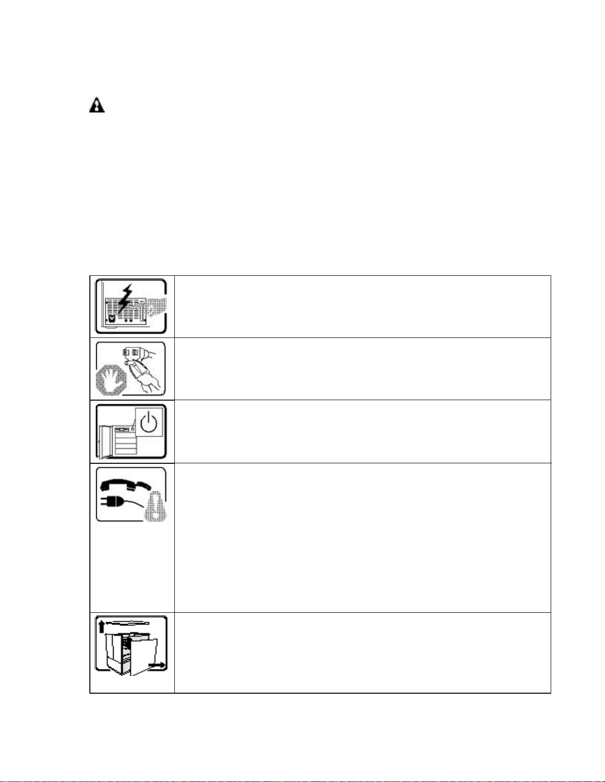
WARNING!
Please read all warnings and instructions BEFORE operating the system.
Avoid Injury: To avoid personal injury when unpacking the system, use
only a mechanical assist unit to lift it off the shipping pallet. The system
weighs approximately 84 lbs.
WARNINGS
The following caution notices apply whenever you remove the access cover to access
components inside the system. Only a technically qualified person should integrate and
configure the system.
The power supply in this product contains no user-serviceable parts. Refer
servicing only to qualified personnel.
Do not attempt to modify or use the supplied AC power cord if it is not the exact
type required.
The DC push-button on/off switch on the system does not turn off system AC
power. To remove AC power from the system, you must unplug each AC power
cord from the wall outlet or power supply.
SAFETY STEPS: Whenever you remove the chassis covers to access the inside
of the system, follow these steps:
1. Turn off all peripheral devices connected to the system.
2. Turn off the system by using the push-button on/off power switch on the system.
3. Unplug all AC power cords from the system or from wall outlets.
4. Label and disconnect all cables connected to the I/O connectors or ports on the
rear of the system.
5. Provide some electrostatic discharge (ESD) protection by wearing an anti-static
wrist strap attached to chassis ground of the system—any unpainted metal
surface—when handling components.
6. Do not operate the system with the chassis covers removed.
After you have completed the six SAFETY steps above, you can remove the
system covers. To do this:
1. Unlock the system from the side using the keys provided.
2. Remove the thumbscrews to remove the side cover.
Continued
22
Page 23
WARNINGS (continued)
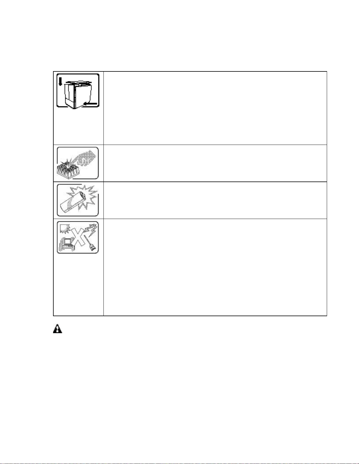
For proper cooling and airflow, always reinstall the chassis covers before turning on
the system. Operating the system without the covers in place can damage system
parts. To install the covers:
1. Check first to make sure you have not left loose tools or parts inside the system.
2. Check that cables, add-in boards, and other components are properly installed.
3. Attach the covers to the chassis with the screws removed earlier, and tighten
them firmly.
4. Lock the system to prevent unauthorized access inside the system.
5. Connect all external cables and the AC power cord to the system.
The microprocessor, heat sink and Power Pod may be hot if the system has been
running. Also, there may be sharp pins and edges on some board and chassis
parts. Contact should be made with care. Consider wearing protective gloves.
Danger of explosion if the battery is incorrectly replaced. Replace only with the
same or equivalent type recommended by the equipment manufacturer. Discard
used batteries according to manufacturer’s instructions.
hp workstation i2000 owner’s guide
The system is designed to operate in a typical office environment. Choose a site
that is:
1. Clean and free of airborne particles (other than normal room dust).
2. Well ventilated and away from sources of heat including direct sunlight.
3. Away from sources of vibration or physical shock.
4. Isolated from strong electromagnetic fields produced by electrical devices.
5. In regions that are susceptible to electrical storms, we recommend you plug your
system into a surge suppresser and disconnect telecommunication lines to your
system during an electrical storm.
6. Provided with a properly grounded wall outlet.
7. Provided with sufficient space to access the power supply cords, because they
serve as the product’s main power disconnect.
WARNING
Do not open the power supply. Risk of electric shock. Refer servicing of the
power supply to qualified service personnel.
23
Page 24

hp workstation i2000 owner’s guide
CAUTION
Before removing the access cover for any reason, observe these cautionary
guidelines.
• Turn off all peripheral devices.
• Turn off the system by pressing the power button on the front of the chassis.
Then unplug the AC power cord from the chassis or wall outlet.
• Label and disconnect all peripheral cables connected to the I/O connectors or
ports on the back of the chassis.
• Provide some electrostatic discharge (ESD) protection by wearing an anti-static
wrist strap attached to chassis ground—any unpainted metal surface—when
handling components.
CAUTION
The power button on the front panel does not disconnect the AC power. To
remove power from the system, you must unplug the AC power cord from the AC
supply or from the computer chassis.
CAUTION
ESD can damage disk drives, boards, and other parts. Perform all procedures in
this chapter only at an ESD workstation. If one is not available, provide some ESD
protection by wearing an anti-static wrist strap attached to chassis groundany
unpainted metal surfaceon your system when handling parts.
Always handle boards carefully. They can be extremely sensitive to ESD. Hold
boards only by their edges. Do not touch the connector contacts. After removing a
board from its protective wrapper or from the system, place the board component
side up on a grounded, static free surface. If you place the server board on a
conductive surface, the battery leads may short out. If they do, this will result in a
loss of CMOS data and will drain the battery. Use a conductive foam pad if
available but not the board wrapper. Do not slide the board over any surface.
For proper cooling and airflow, always install the chassis side cover before turning
on the system. Operating it without the cover in place can damage system parts.
24
Page 25

hp workstation i2000 owner’s guide
1. introduction
The i2000 system is an Intel Itanium™- based workstation. It features the Intel ®
82460GX PCI set, multiple 64-bit/ 66 MHz PCI expansion slots, support for AGP Pro*
110 graphics cards and large memory capacity (16 GB). The product is configured as
follows:
• One- (1) 733 MHz or two- (2) 800 MHz Intel Itanium™ processors
• Two- (2) Memory Expansion Cards supporting up to 16 GB SDRAM
• One- (1) I/O card supporting USB, IDE, PS/2, Audio, and 10/100 Mbps LAN
• One- (1) Quantum* Hard Drive (18 GB)
• One- (1) LS-120 drive or LS-240
• One- (1) DVD-ROM drive (Hitachi)
• One- (1) Qlogic* 12160 Dual Channel Ultra 3
• One- (1) nVIDIA Quadro2 Pro video card
• 800 WTX power supply
• PS/2 keyboard and mouse
1.1 Chassis Description
The i2000 workstation is housed in a WTX compliant chassis. It is designed to
accommodate the needs of a variety of high-performance applications. As application
requirements increase, the system can be upgraded with:
• Dual processor
• Additional memory modules
• Add-in PCI based adapters
• Additional SCSI devices
• Additional IDE devices
• Other peripheral devices
25
Page 26
hp workstation i2000 owner’s guide
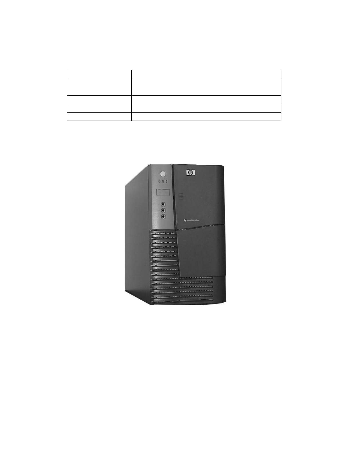
Table 1. Physical Specifications
Specification
Height
Width 25.40 cm (10 inches)
Depth 64.52 cm (25.4 inches)
Weight 38.18 kg (84 lbs.)
44.45 cm (17.5 inches) without feet
45.72 cm (18 inches) with standard feet
Value
Figure 1. Workstation System Chassis
26
Page 27

hp workstation i2000 owner’s guide
1.2 Chassis Features Summary
Table 2. Chassis Features Summary
Feature Comment
Power system An 800 W power supply that is capable of operating over input voltage ranges of 100-240
VAC. Includes two- (2) integrated 80-mm fans for cooling.
Workstation chassis Designed to operate in a standard office environment. Mid-tower (desk side) design capable
of operating from a standard AC power outlet.
Peripheral bay can accommodate up to three- (3) 5.25-inch media and one- (1) 3.5-inch media
devices.
The hard drive bay accepts 3.5-inch-wide drives. It can accommodate up to five- (5) 1-inch or
three- (3), 1.6-inch devices.
The plastic front bezel provides airflow and easy access to the peripheral and hard drive bays.
The removable top and side covers provide proper airflow and easy access to components
inside the system. Only technically qualified personnel should remove the system covers.
Cooling system The system has provisions for up to eight- (8) fans for cooling within four- (4) separate cooling
zones. There are two- (2) 120-mm fans, one- (1) 92-mm fan, four- (4) 80-mm fans, and one(1) 60-mm fan.
System security A side lock and chassis intrusion switch provides security against system tampering. The
intrusion switch can be used with system level software (when it becomes available) to warn of
chassis intrusion.
27
Page 28
hp workstation i2000 owner’s guide
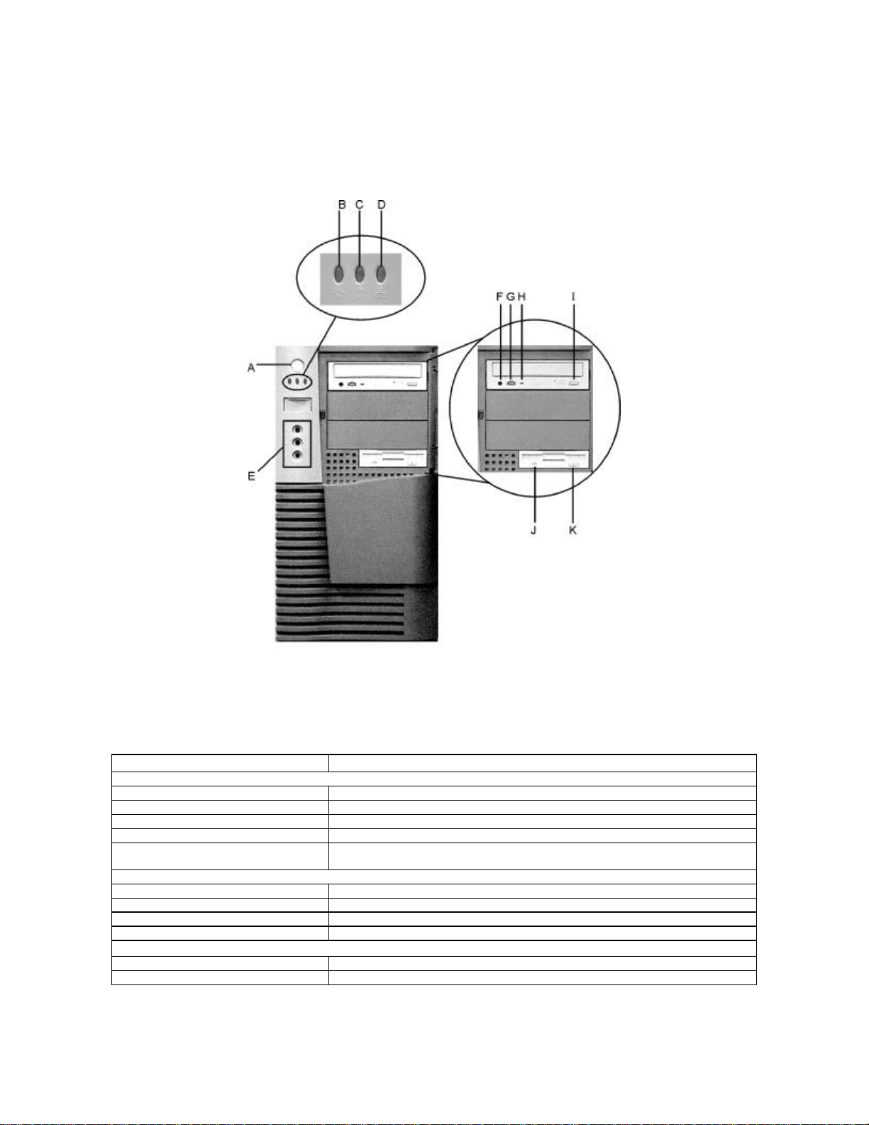
1.2.1 Chassis Front Controls and Indicators
Item Feature / Description
Front Panel
A. Power Switch
B. Power LED
C. Drive activity LED
D. LAN LED
E. USB ports and Audio Connections (Pink =MIC, Blue =Line In, Green =Speaker
DVD Drive
F. Headphone Jack
G. Volume control
H. Activity LED
I. Open/Close button
3.5-inch Diskette Drive (LS-120)
J. Activity LED
K. Ejector button
Figure 2. Front Controls and Indicators
Table 3. Front Panel Components
out)
28
Page 29
hp workstation i2000 owner’s guide
B C D E F G H
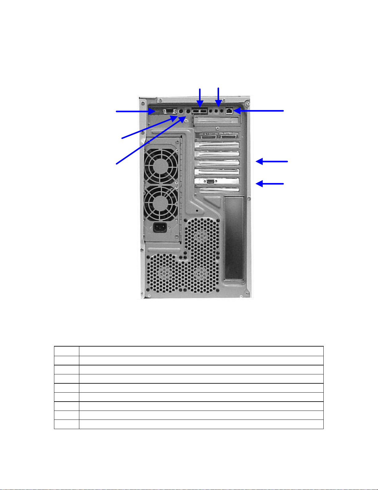
1.2.2 Chassis Rear Controls and Features
A
Figure 3. Chassis Rear View
Table 4. Chassis Rear Components
Item Feature / Description
A. Serial port
B. PS/2 compatible, 6-pin mouse connector
C. PS/2-compatible, 6-pin keyboard connector
D. Two- (2) USB ports, 4-pin connector
E. Audio Connections (Pink =MIC, Blue =Line In, Green =Speaker out)
F. LAN (10/100 Mbps)
G. One- (1) SCSI Qlogic* card
H. AGP video card (nVIDIA Quadro2 Pro)
29
Page 30

hp workstation i2000 owner’s guide
/ NOTE
The i2000 system has a Qlogic* SCSI Host Bus Adapter installed with two- (2)
external SCSI connectors accessible from the system rear panel.
The components in the previous figure are for illustration purposes only. Actual
card location may vary slightly.
1.3 Peripheral Bay
The peripheral bay can accommodate one- (1) 3.5-inch and three- (3) 5.25-inch devices.
The DVD ROM and the LS-120 drives are housed in the peripheral bay. Both devices
are accessible from the front of the chassis (Refer to Figure 3.)
/ NOTE
For continued safety compliance of the system, use only peripheral devices,
which are marked as UL recognized compliant components and that are also CE
marked. Additionally, for all optical drives such as CD-ROM, DVD, etc. laser
safety compliance is required to both U.S. code 21CFR, chapter 1, subchapter J,
part 1040.10 and International Standard EN60825-1, Safety of Laser Products.
For continued EMC compliance of the system, use only those peripheral devices
having an external output connector (i.e., audio, video), which are marked as
FCC tested for home or office use (FCC Class B), and marked as Canada ICES003 Class B compliant. For European installations, these devices are required to
be CE marked with declaration of conformity to the EMC directives
(89/336/EEC).
/ NOTE
System EMI integrity and cooling are both protected by having drives installed in
the bays or filler panels and EMI shields covering the bays. When you install a
drive, save the panel and shields to reinstall incase you should later remove the
drive and not reinstall one in the same bay.
1.3.1 LS-120 Drive
The LS-120 drive (located in the peripheral bay) supports 120 MB and 1.44 MB media.
30
Page 31

hp workstation i2000 owner’s guide
1.3.2 DVD ROM Drive
In the i2000 system, the DVD ROM drive in the peripheral bay consists of an IDE device.
1.3.3 Hard Drive Bay
The hard drive bay is designed for 3.5-inch-wide hard drives. It can accommodate up to
five- (5) 1-inch-high or three- (3) 1.6-inch-high drives.
1.4 Power Supply
The chassis is configured with a single, 800 W power supply. It is capable of providing
full rated output power over a range of input voltages, 100-240 VAC. The power supply
features automatic Power Factor Correction (PFC), and is connected to the system
boards using the following connectors:
• A 24-pin baseboard connector providing +3.3 Vdc and +5 Vdc
• A 22-pin baseboard connector with +3.3 Vdc, +5 V
• An 8-pin connector for memory power with an output voltage 12 Vdc
• A 6-pin connector for the processor Power Pod with an output voltage of 12 Vdc
• A 16-pin connector with outputs of +5 V
For ease of replacement, the connectors can be disconnected from the power supply
and the power supply replaced without removing the system boards or unhooking any
connectors from the boards.
and +12 V
dc
+12 V
dc,
dc
dc
for peripherals
and –12 Vdc outputs
1.5 System Cooling
Support for eight- (8) fans within four- (4) separate zones (regions of the system) is
provided for the following configuration:
• Zone 1 - Processor: two- (2) fan headers for two- (2) 120-mm fans.
• Zone 2 - Memory: one- (1) fan header for one- (1) 80-mm fan.
• Zone 3 - I/O: two- (2) fan headers for one- (1) 92-mm and one- (1) 60-mm fan.
• Zone 4 - Exhaust: three- (3) fan headers for three- (3) 80-mm fans, but only
one- (1) is populated in the reference system configuration.
i2000 utilizes three- (3) wire fans; two- (2) wires provide power, another provides the fan
tachometer output. Utilizing a three-wire fan allows the system to monitor the fan speed
and control the speed via the power source with sensing from a thermister (on-board or
remote).
31
Page 32

hp workstation i2000 owner’s guide
/ NOTE
If you replace a system fan, check the orientation. Replace any failed fans with
the same or equal type as the one(s) failed. Replacement fans should have the
same rated voltage, wattage, and CFM as the original fan(s) being replaced.
32
Page 33

hp workstation i2000 owner’s guide
2. Board Set Description
The architecture of the i2000 system supports Symmetrical Multiprocessing (SMP). The
system board set consists of:
• Baseboard
- Seven- (7) PCI expansion slots (five- (5), 64-bit/66 MHz, two- (2) Intel
64-bit /33 MHz)
- AGP Pro* 110 connector
- Processor board connector
- Memory Expansion Card connectors (2)
- Integrated Voltage Regulators
• Processor board
- Two- (2) Intel Itanium™ processor LIF sockets
- ITP connector
• Memory board
- Two- (2) Memory Expansion Cards
- Eight- (8) DIMM sites on each MEC
- Each MEC supports up to 8 GB
- Memory DC-DC converters
• I/O board
- ATA-33 IDE (primary & secondary channels)
- USB (dual port)
- Front panel connectors (Audio & USB)
- LAN (10/100 Mbps)
- PS/2 (keyboard & mouse)
- Audio
- 9-pin Serial
33
Page 34
hp workstation i2000 owner’s guide
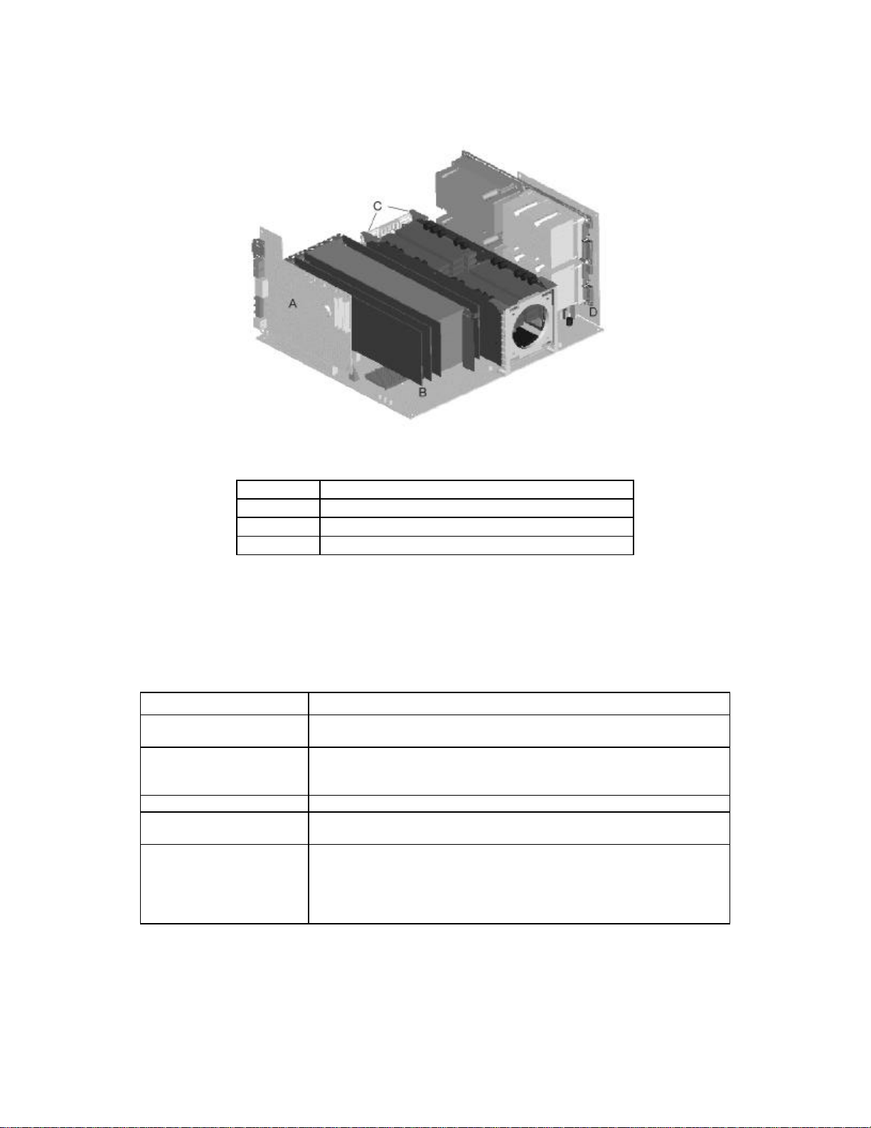
Figure 4. Board Set Overview
A
B
C
D
I/O Board
Baseboard
Memory Expansion Cards
Processor Board
2.1 Board Set Features
Table 5. Board Set Features
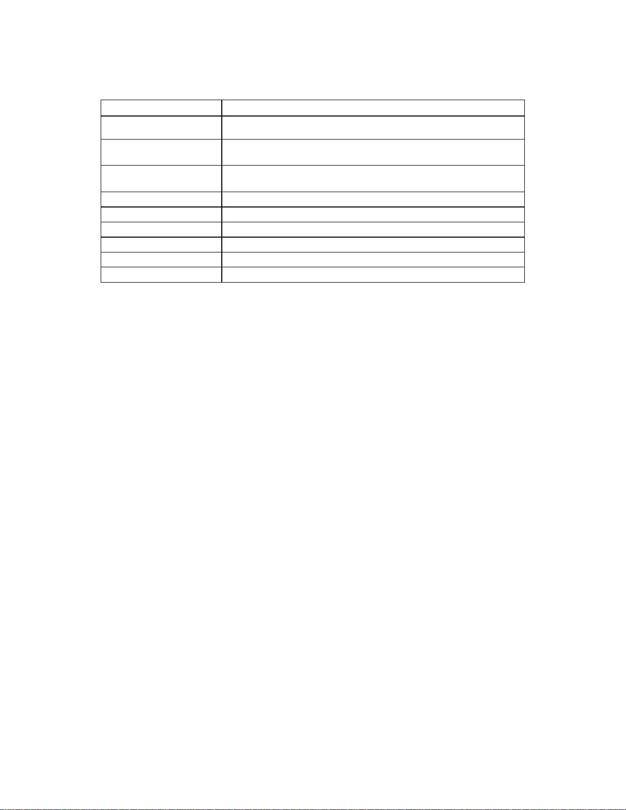
Feature Description
Baseboard The baseboard provides the interface for the processor board, memory
expansion cards, I/O board, PCI peripherals and AGP Pro*.
Processor board The processor board can support a maximum of two- (2) Intel Itanium™
processors, two- (2) processor power pods and an ITP connector. An add-in
bus terminator is not required for single processor configurations.
Intel Itanium™ processor Capable of supporting up to two- (2) Intel Itanium™ processors.
Power Pod Can support up to two- (2) Power Pods to supply power to the Itanium™
processors.
Memory Expansion Cards Two- (2) plug-in expansion cards supporting PC100 registered SDRAM
containing interleaved pathways to main memory. Each memory card supports
from 256 MB to 8 GB of error correction code (ECC) memory using eight- (8) 72-
bit dual inline memory modules (DIMMs). These modules interface to the
baseboard through 300-pin connectors.
34
Page 35
hp workstation i2000 owner’s guide
Feature Description
I/O Board The I/O board plugs into the SC242 connector at the left side of the baseboard
(PCI connectors oriented top).
The ATA-33 Integrated Drive Electronics (IDE) interface supports one- (1)
primary and one- (1) secondary IDE channel.
Four- (4) universal serial bus (USB) ports. Two- (2) rear I/O USB connectors
and a header for two- (2) front panel USB ports.
Audio Connections (Pink =MIC, Blue =Line In, Green =Speaker out)
LAN (10/100 Mbps)
One- (1) 9-pin serial port
Front panel Audio and USB
Push-button power switch
LEDs indicate power and hard drive activity
2.1.1 Processor Overview
The Intel Itanium™ processor is the first in a family of high-performance Itanium
processors. Intel’s Itanium™ Instruction Set Architecture (ISA) is referred to as Intel
Itanium™ architecture. The Itanium™ processor maintains full compatibility with Intel’s
current 32-bit Intel Architecture processor family while delivering industry-leading
performance beyond existing architectures. Each Intel Itanium™ processor is
packaged in a PAC418 (418-pin array cartridge) format. The cartridge includes:
• The processor core
• L1 instruction cache (16 KB, on die)
• L1 data cache (16 KB, on die)
• Unified L2 cache (96 KB, on die)
• Unified L3 cache (2 MB or 4 MB)
• A thermal plate
/ NOTE
Each processor implements the MMX™ and SSE (Streaming SIMD Extensions)
technology.
35
Page 36
hp workstation i2000 owner’s guide
2.1.2 Memory Overview
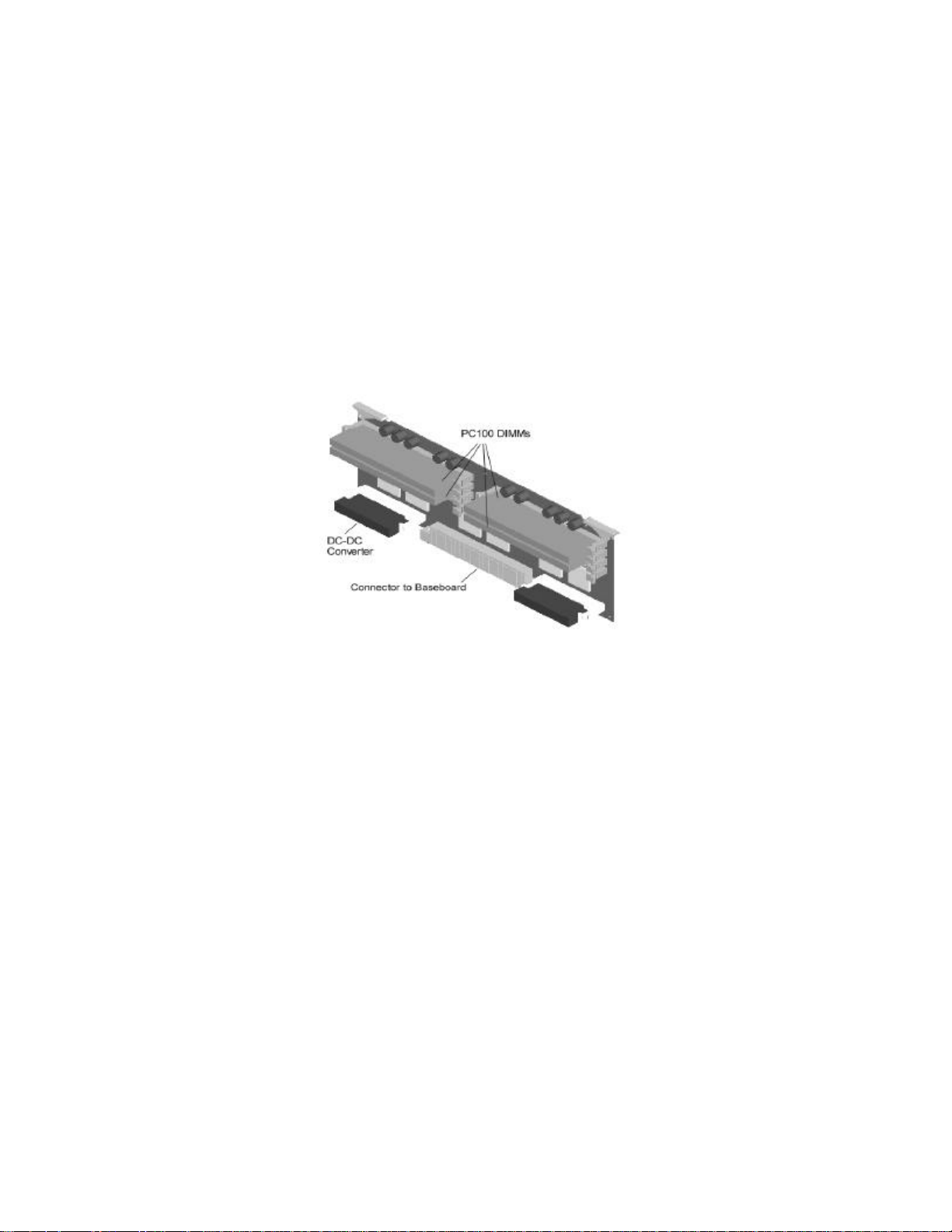
Main memory resides on two- (2) add-in boards called Memory Expansion Cards
(MECs). Each MEC contains sites for eight- (8) DIMMs and two- (2) power connectors
for DC-DC converters. Each MEC is attached to the baseboard through a 300-pin
connector. The memory controller supports PC100 registered SDRAM DIMMs. The
memory sub-system can operate in two- (2) different modes.
• Interleaved Mode: (two- [2] MECs installed). This configuration offers the
highest performance by dividing the total system RAM across two- (2) MECs.
This reduces the probability of wait states, thus increasing speed on sequential
accesses. To operate in interleaved mode, BOTH MECs MUST BE USED WITH
AT LEAST THE TOP FOUR- (4) DIMM SITES POPULATED ON EACH MEC.
• Single-port Mode: (one- [1] MEC installed). The single MEC responds to all
memory addresses.
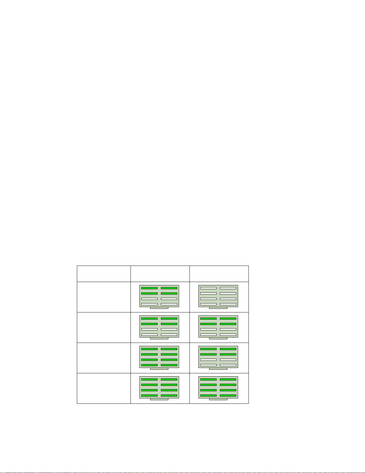
2.1.3 DIMM installation sequence
The DIMMs must be installed within groups of four- (4). Each board has eight- (8) DIMM
sites. The top four- (4) DIMM sites form the top, or right, stack while the bottom four- (4)
DIMM sites form the bottom, or left, stack (on each of the two- [2] boards). Refer to
Figure 5.
Installing i2000 RAM Accessory DIMMs
Number of DIMMs
Installed
(4) DIMMs
(8) DIMMs
(12) DIMMs
Memory Expansion
Card A
Memory Expansion
Card B
(16) DIMMs
Figure 5. Memory Board Stacks
36
Page 37
hp workstation i2000 owner’s guide
/ NOTE
DIMMs must be installed in groups of four- (4) with all DIMMs within a stack
being of the same size, type, and manufacturer.
For optimum performance, the stacks must also be populated in the proper order
with the same size of DIMMs. The memory subsystem can operate in two- (2)
different modes, interleaved or single-port.
If a single memory board is used, a minimum of four- (4) DIMMs must be populated in
the top stack. The minimum memory configuration is illustrated in Figure 5.
Figure 5. Memory Expansion Card
For optimum performance, both memory cards should be installed with the top four- (4)
DIMM slots populated with the same size, type, and brand of memory. This
recommendation utilizes both memory ports and achieves maximum memory bandwidth.
2.2 Peripherals
2.2.1 Product I/O
The LPC47B27 Super I/O device supports one- (1) serial port and PS/2-compatible
Keyboard and Mouse ports. The system provides the connector interface for each port.
The I/O and Firmware Bridge (IFB) on the I/O card contains an integrated USB host
controller supporting two- (2) USB ports. These can be accessed from the back of the
system. In addition, a USB hub provides support for two- (2) additional ports via the
front panel of the system. Neither parallel ports nor Legacy FDD are supported.
a) Serial Port
37
Page 38

hp workstation i2000 owner’s guide
The system features a single 9-pin serial port located on the rear I/O panel.
38
Page 39
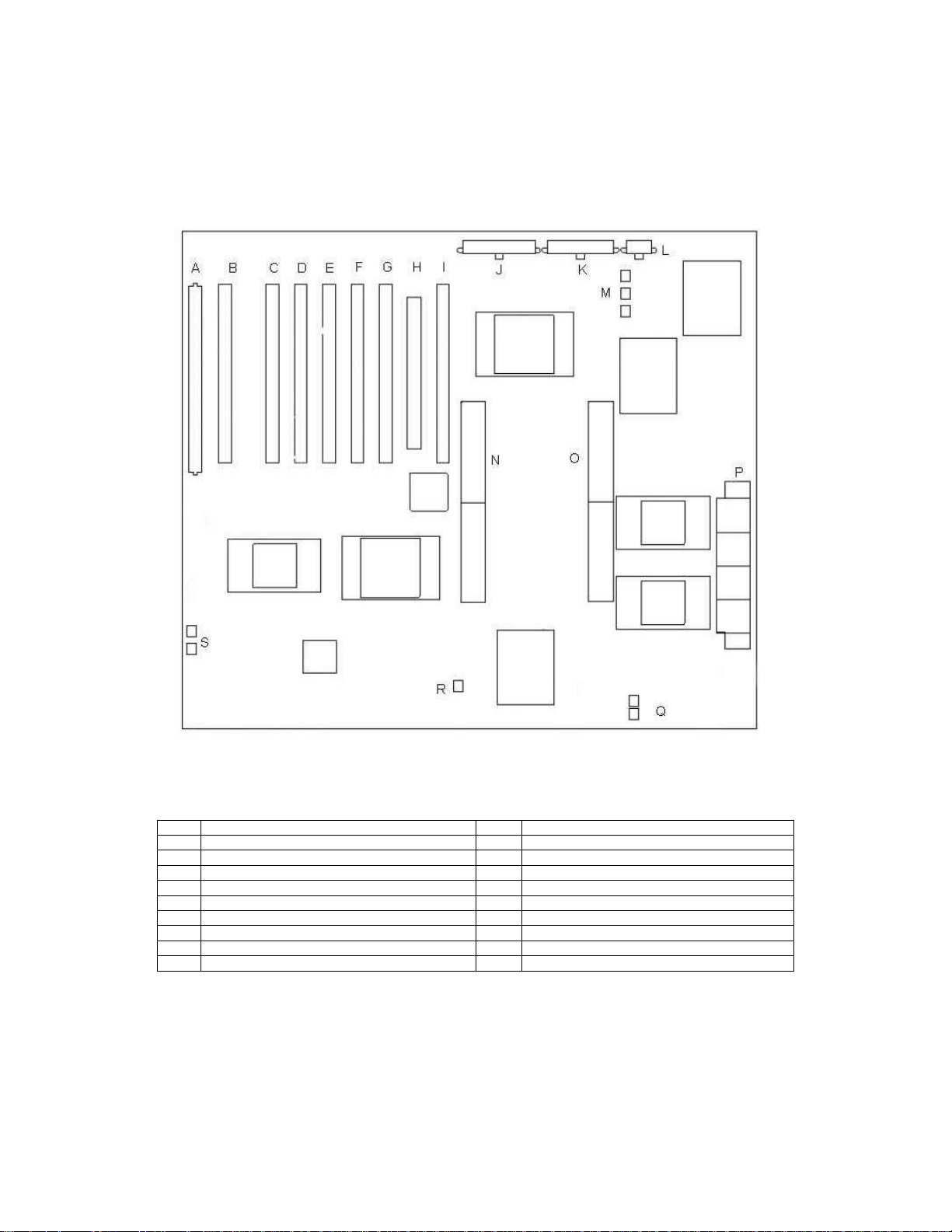
2.3 Baseboard Connectors
hp workstation i2000 owner’s guide
Figure 6. Baseboard Connectors
A I/O board connector K 22-pin power connector
B PCI slot S2 (64-bit /66 MHz, 3.3 V) L 8-pin power connector
C PCI slot 1 (64-bit /66 MHz, 3.3 V) M Zone 4 (exhaust) fan connectors
D PCI slot 2 (64-bit /66 MHz, 3.3 V) N Memory board connector A
E PCI slot 3 (64-bit /66 MHz, 3.3 V) O Memory board connector B
F PCI slot 4 (64-bit /66 MHz, 3.3 V) P Processor board connector
G PCI slot 5 (64-bit /33 MHz, 5 V) Q Zone 1 (processor) fan connectors
H AGP Pro 110 connector R Zone 2 (memory) fan connector
I PCI slot 6 (64-bit /33 MHz, 5 V) S Zone 3 (I/O) fan connectors
J 24-pin power connector
39
Page 40

hp workstation i2000 owner’s guide
2.3.1 PCI
The baseboard has two- (2) 64-bit, 66 MHz PCI buses and one- (1) 64-bit, 33 MHz PCI
bus.
• The WXB (Wide eXpansion Bridge) PCI bus 1 provides PCI slots 1, 2, and S2.
• The WXB (Wide eXpansion Bridge) PCI bus 2 provides PCI slots 3 and 4.
• The PXB (PCI eXpansion Bridge) PCI bus 0 provides PCI slots 5, 6, and IFB.
• The IFB controls communications to IDE, USB, and Super I/O.
/ NOTE
For continued EMC compliance of the system, use only those peripheral devices
having an external output connector (i.e., audio, video), which are marked as
FCC tested for home or office use (FCC Class B), and marked as Canada ICES003 Class B compliant. For European installations, these devices are required to
be CE marked with declaration of conformity to the EMC directives
(89/336/EEC).
2.3.2 AGP
The baseboard provides support for AGP Pro 110 (4x @ 66 MHz) for high-end graphics
capability.
2.4 Video
An nVIDIA Quadro2 Pro provides video on the hp workstation i2000.
2.5 LAN
The I/O board supports integrated 10/100 Mbps LAN support (using the Intel® 82559
Fast Ethernet controller). An RJ45 connector accessible via the rear I/O panel is
provided for this purpose.
2.6 SCSI Controller
The i2000 workstation includes one- (1) QLogic* 12160 based SCSI Host Bus Adapter
(HBA) capable of Ultra3 Low Voltage Differential (LVD) data and control transfers at 160
MB/s.
40
Page 41

hp workstation i2000 owner’s guide
2.7 IDE Controller
IDE is a 16-bit interface for integrated disk drives with AT* disk controller electronics
onboard. The IFB (I/O and Firmware Bridge) is a multifunction device on the I/O board
that acts as a PCI-based Fast IDE controller. The device controls:
• PIO Mode 4 and DMA/bus master operations
• Transfer rates up to 22 MB/sec (33 MB/sec using Ultra DMA transfers)
• Buffering for PCI/IDE burst transfers
• Primary and secondary channels
2.8 Keyboard and Mouse
Two- (2) PS/2 ports are provided for keyboard and mouse. They are located at the rear
of the system. USB keyboard and mouse connectors are available.
2.9 Front Panel Connectors
The chassis front panel includes:
• Power switch
• Power LED
• HDD activity LED
• LAN activity LED
• USB Connectors (two- [2] ports)
• Audio Connections (Pink = MIC, Blue = Line In, Green = Speaker out)
41
Page 42

hp workstation i2000 owner’s guide
3. BIOS - Overview
This system uses Intel ® proprietary BIOS stored on the 82802AC FWH and can be
upgraded using an LS-120 disk-based firmware flash utility. Table 6 provides an
overview of the features supported by the i2000 BIOS.
Table 6. BIOS Features
Feature Description
BIOS Upgrades Flash memory upgrades using LS-120
Enhanced IDE
ATAPI
System Management System and chassis information is loaded into SMBIOS tables from
ACPI
Video Support
Available Languages English (U.S.)
Boot Options
OEM Logo or Scan Area OEM logo area in flash
USB Legacy USB keyboard and mouse support
BIOS Security Features
BIOS Recovery Recovery BIOS included in flash
SMBIOS Compliant with SMBIOS 2.3
• PIO Mode 4
• Ultra DMA 33*
• Auto configuration
• LBA
• Two channels, support for master and slave drives on each channel
• LS-120 support
• CD-ROM
• DVD
IDROMs
• Power management support
• Software power off
• The BIOS supports the following ACPI states:
- S0 (Normal power on)
- S1 (Processor Sleep)
- S4 (Suspend to Disk)
- S5 (Normal power off)
• Supports wake up on:
- Power/sleep switch
- RTC alarm
- LAN
- Modem
- PME
• Supports 1X, 2X, or 4X AGP graphics
• AGP Pro 110 support
• 32 or 64-bit PCI graphics card support
• Hard drive (SCSI)
• DVD
• ARMD-HDD (LS-120)
• Network boot support
• User and Administrative passwords
• Security for flash contents
42
Page 43
hp workstation i2000 owner’s guide
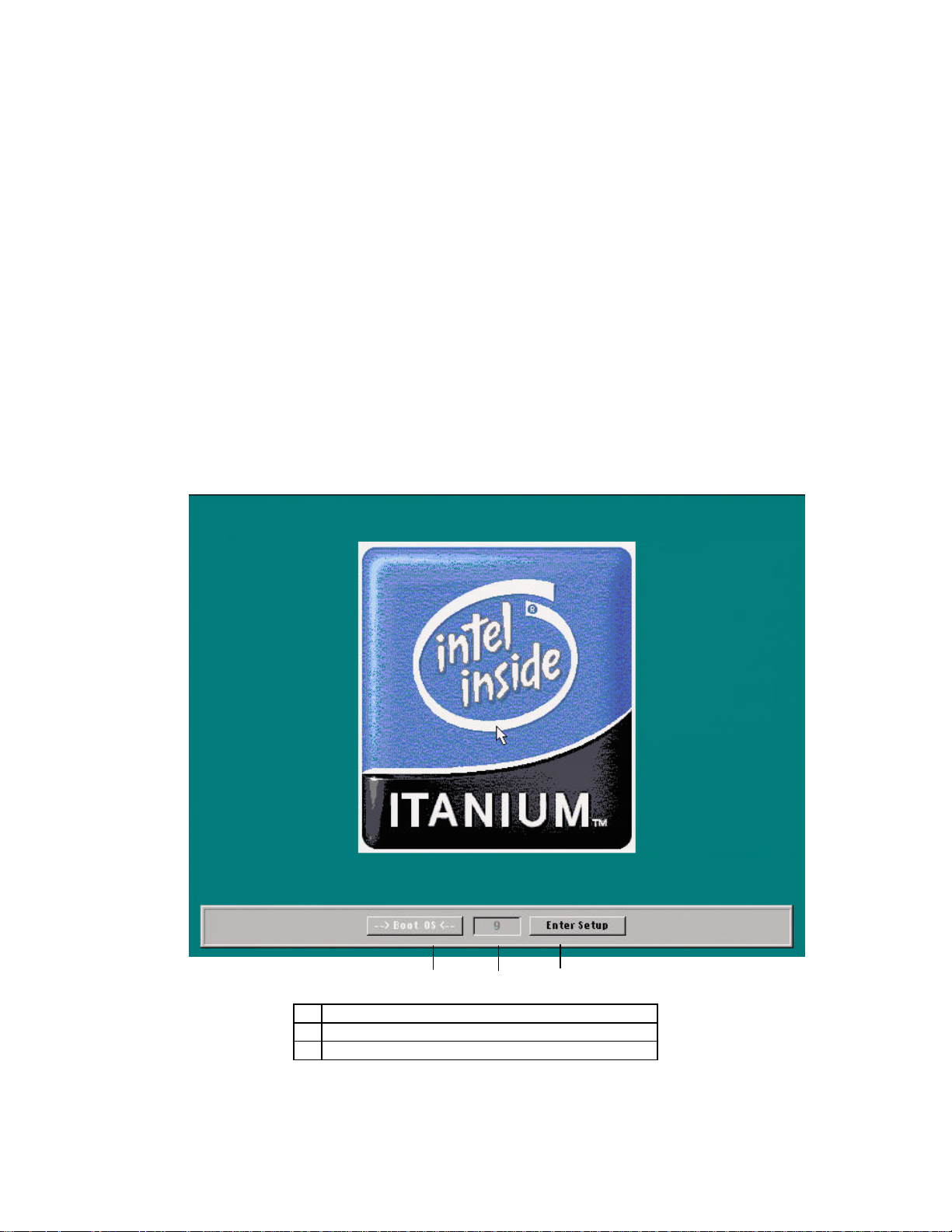
B A
3.1 Entering and Exiting the Configuration
Manager
The BIOS displays a screen with the manufacturer's logo (refer to Figure 7) shortly after
the start of the boot sequence. You have two choices before proceeding:
1. Choose Enter Setup to view the Configuration Manager.
2. Choose Boot OS to dismiss the introductory screen and continue booting the
operating system.
The label for the currently selected button is white and enclosed by right (“-->”) and left
(“<--”) arrows. To move the current selection between the two buttons, left-click the
desired button with the mouse. You may also press the Tab key or the left and right
arrow keys. The text box between the two buttons (Figure 7) shows the number of
seconds remaining before the BIOS automatically continues with the selected option.
A Boot OS (operating system)
B Time remaining before executing selected option
C Enter Configuration Manager (Setup)
Figure 7. Full Screen Logo with Buttons to Enter Setup or Boot OS
C
43
Page 44

hp workstation i2000 owner’s guide
To exit Configuration Manager, do the following:
1. Go to the Save/Exit Tab (refer to section 3.13).
2. If you have made changes in the Configuration Manager Settings, choose
Save New Settings or Discard Changes.
3. Choose Exit.
3.2 Configuration Manager Tabs
/ NOTE
For reference purposes, before you begin record the current settings in Appendix
B. When you make changes to the settings, update this record.
The Configuration Manager is accessed at the Intel Itanium™ processor Splash
Screen (refer to Figure 8) by tabbing to the “Enter Set-up” option and pressing enter.
The Configuration Manager is organized into a set of tabbed panels. Table 7
summarizes the uses for each tab.
Table 7. Summary of Configuration Manager Screens
Tab Legend Uses
Help Help on using the Configuration Manager
System Processors • Displays processor information
• Displays the Front Side Bus (FSB) speed
System Memory • Displays the amount of memory
• Displays the memory speed
• Displays the ECC setting
• Displays the type of memory module in each slot
System Event Log • Configure System Event Log
• Mark System Event Log as read
• View System Event Log
Integrated IDE • Controller Enabled
• Spin Delay
• Configure the Primary and Secondary IDE channels
System BIOS • Displays the BIOS version
• Displays the SMBIOS version
• Displays the PAL version
• Displays the SAL version
• Displays the Boot Block version
Power Events Enable or disable the S5 wake-up events
Time/Date Displays and sets the time or date
44
Page 45

hp workstation i2000 owner’s guide
Tab Legend Uses
General • Set the amount of time the introductory screen remains visible
• Enable or disable the on-board Network Interface Card (NIC)
• Enable or disable the on-board audio device
• Set resume after AC power failure to on or off
• Enable or disable Num Lock at power-on
• Sets the COM port for Serial Port 1
Security Set or clear the User and Administrator Passwords
Save/Exit • Save or discard the changes
• Load the default settings
• Exit Configuration Manager
3.2.1 Using the Keyboard and Mouse in Configuration
Manager
You can use your keyboard and mouse together to navigate in the Configuration
Manager, however, the mouse is the preferred method.
Table 8. Keyboard Usage in Configuration Manager
Mouse Use the left mouse button to select tabs or buttons. Use the right mouse button to
display the on-line help for the selected tab. If you have swapped the left and right
mouse buttons in your Operating System that setting is not in effect while you are using
the Configuration Manager.
Backspace Use the Backspace key when entering text to erase the previous character.
Tab key Use the Tab key to move to the next control.
Shift+Tab key Use the Shift+Tab key to move back one control.
ESC key Use the ESC key to jump to the Save/Exit Tab.
F1 key Use the F1 key to display help text for the selected tab.
Right Arrow Use the Right Arrow key to move to the next Tab panel to the right.
Left Arrow Use the Left Arrow key to move to the next Tab panel to the left.
Space Bar If the focus is on a checkbox, use the Space Bar to toggle the check box on or off.
Enter If the focus is on a button, use the Enter key to activate the button.
Up/Down Arrows If the focus is on a combo box (a text box with a drop down list), the Up and Down
Arrows will select the previous or next option.
If the focus is on a spin box, the Up and Down Arrows will select the previous or next
value.
45
Page 46
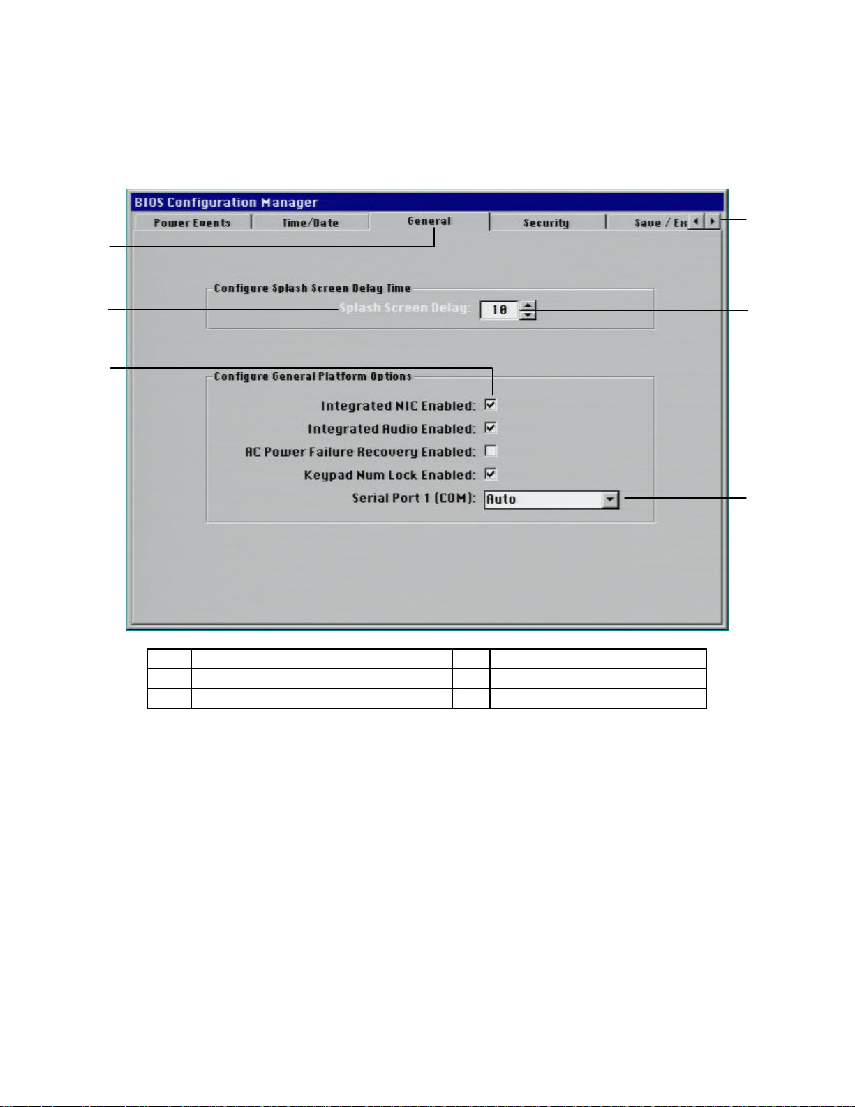
hp workstation i2000 owner’s guide
D
CBA
Figure 8 is an example of a tab in the Configuration Manager. The legend indicates
options that you may find on various tabs.
E
F
A
Active tab panel
B
Label turns white to indicate focus
C
Checkbox
D
Previous tab and next tab buttons
E
Spin button
F
Drop-down list
Figure 8. Configuration Manager Controls
46
Page 47
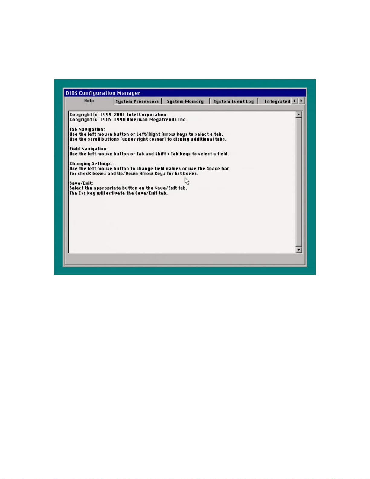
3.3 Help Tab
hp workstation i2000 owner’s guide
Figure 9. Help Tab
The Help Tab lists the keyboard navigation shortcuts used by Configuration Manager.
For help on any Tab, press F1, or click the right mouse button.
47
Page 48
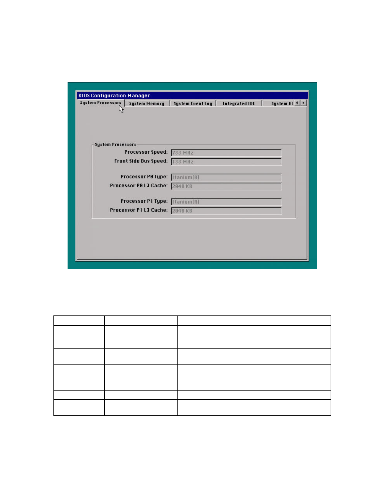
hp workstation i2000 owner’s guide
3.4 System Processors Tab
Figure 10. System Processors Tab Example
Table 9. Description of the System Processors Tab
Feature Options Description
Processor Speed No options Displays the processor speed detected by the BIOS. If two- (2)
processors are installed, both processors have the same
processor speed.
Front Side Bus
Speed
Processor P0 Type No options Displays the processor type.
Processor P0 L3
Cache
Processor P1 Type No options Displays the processor type.
Processor P1 L3
Cache
No options Displays the front side bus speed detected automatically by the
BIOS.
No options Displays the amount of L3 cache RAM for the processor. The L3
cache is located on the processor cartridge.
No options Displays the amount of L3 cache RAM for the processor. The L3
cache is located on the processor cartridge.
48
Page 49
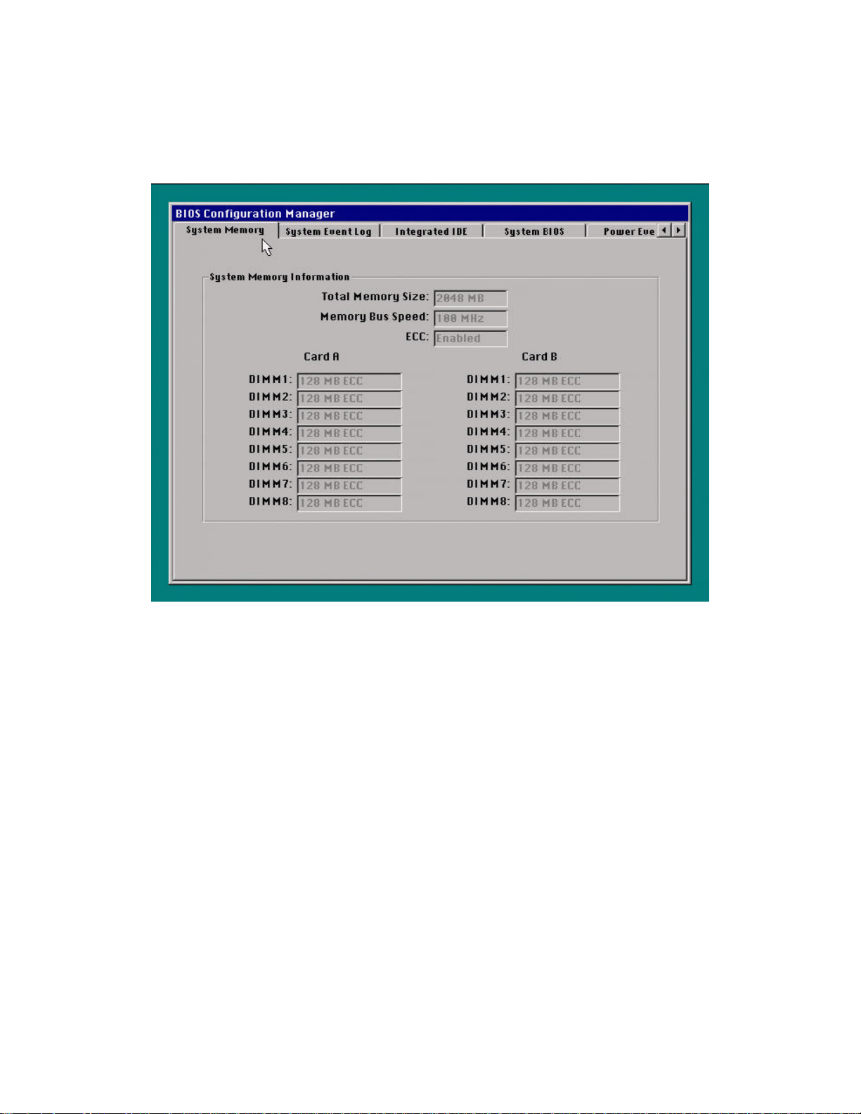
3.5 System Memory Tab
hp workstation i2000 owner’s guide
Figure 11. System Memory Tab Example
49
Page 50

hp workstation i2000 owner’s guide
Figure 12. Description of the System Memory Tab
Feature Options Description
Total Memory Size No options Displays the total amount of SDRAM on the workstation board.
Memory Speed No options Displays the speed of the installed memory.
ECC Setting No options Displays whether or not ECC mode is enabled.
Card A DIMM 1 No options Displays the size and type of memory installed in this slot.
Card A DIMM 2 No options Displays the size and type of memory installed in this slot.
Card A DIMM 3 No options Displays the size and type of memory installed in this slot.
Card A DIMM 4 No options Displays the size and type of memory installed in this slot.
Card A DIMM 5 No options Displays the size and type of memory installed in this slot.
Card A DIMM 6 No options Displays the size and type of memory installed in this slot.
Card A DIMM 7 No options Displays the size and type of memory installed in this slot.
Card A DIMM 8 No options Displays the size and type of memory installed in this slot.
Card B DIMM 1 No options Displays the size and type of memory installed in this slot.
Card B DIMM 2 No options Displays the size and type of memory installed in this slot.
Card B DIMM 3 No options Displays the size and type of memory installed in this slot.
Card B DIMM 4 No options Displays the size and type of memory installed in this slot.
Card B DIMM 5 No options Displays the size and type of memory installed in this slot.
Card B DIMM 6 No options Displays the size and type of memory installed in this slot.
Card B DIMM 7 No options Displays the size and type of memory installed in this slot.
Card B DIMM 8 No options Displays the size and type of memory installed in this slot.
/ NOTE
An asterisk * on the screen indicates that the bank is invalid.
50
Page 51
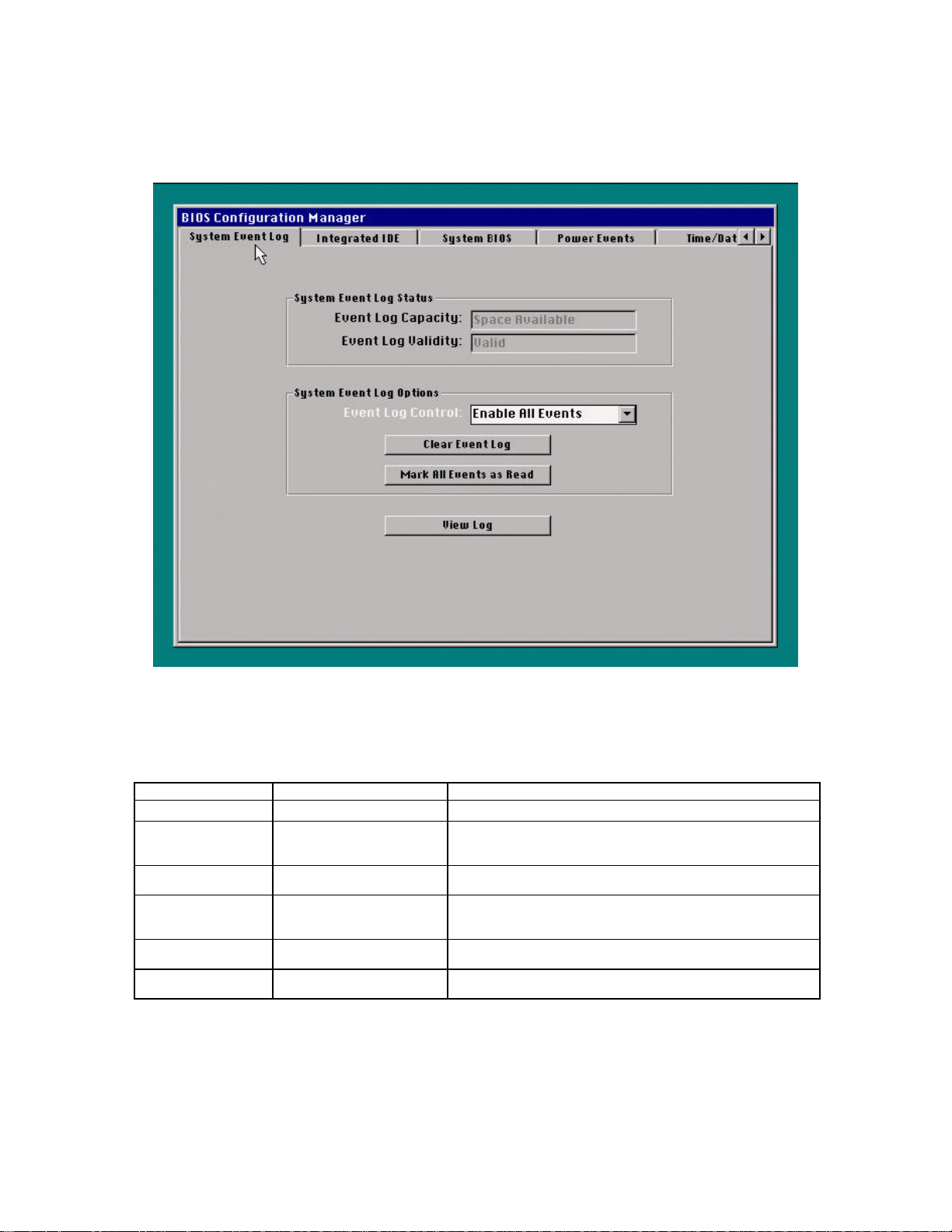
3.6 System Event Log Tab
hp workstation i2000 owner’s guide
Figure 13. System Event Log Tab Example
Table 10. Description of the System Event Log Tab
Feature Options Description
Event Log Capacity
Event Log Validity Display only Shows the information in the event log as valid or invalid. If the
Clear Event Log on
Reboot
Event Log Control
Mark All Events as
Read
View Log Button Displays the system events in the System Event Log (refer to
Display only Shows space availability for the event log.
System Event Log is marked as invalid, clear the Event Log and
Enabled
Disabled (default)
Enable All Events (default)
Disable All Events
Disable ECC Events
Button Mark all events in the log as read.
reboot.
Enable this option to clear the event log each time the system is
rebooted.
Enable or disable event logging. Disable ECC Events will enable
logging all events except for ECC events
Figure 14). Read events are marked with an asterisk.
51
Page 52
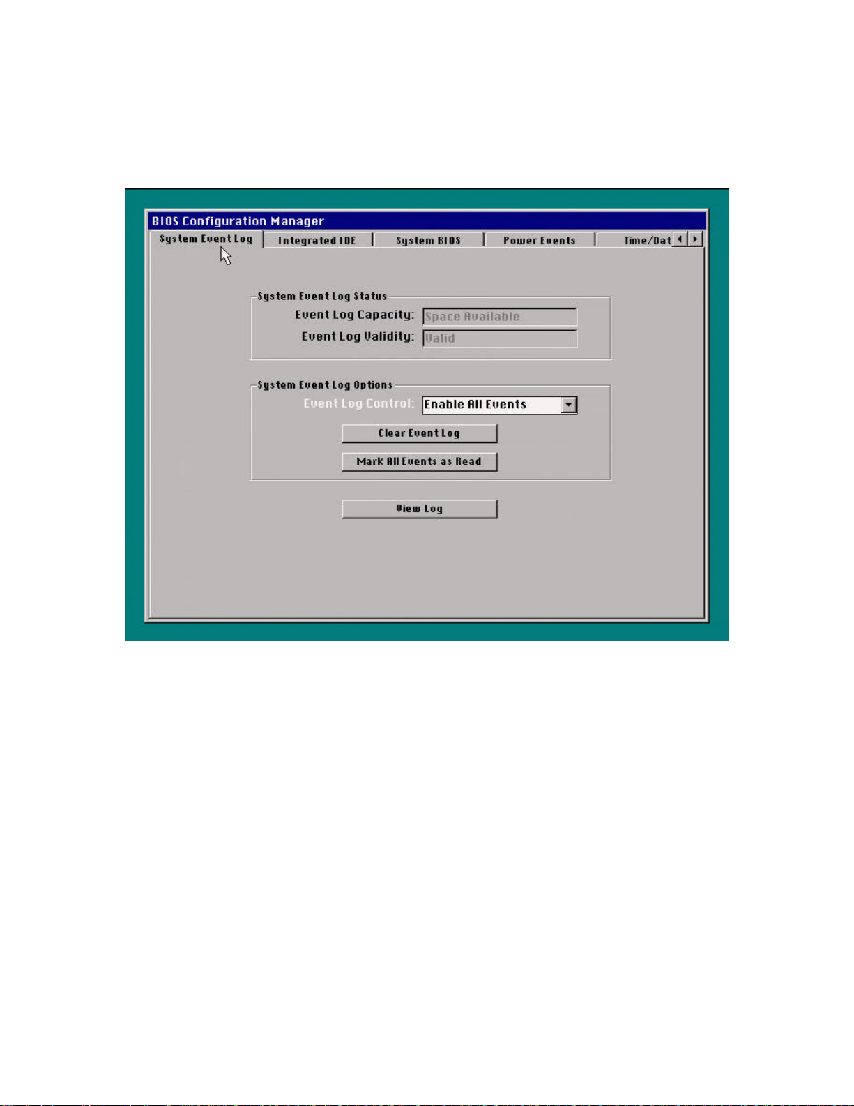
hp workstation i2000 owner’s guide
Figure 14. Sample View of System Event Log
52
Page 53
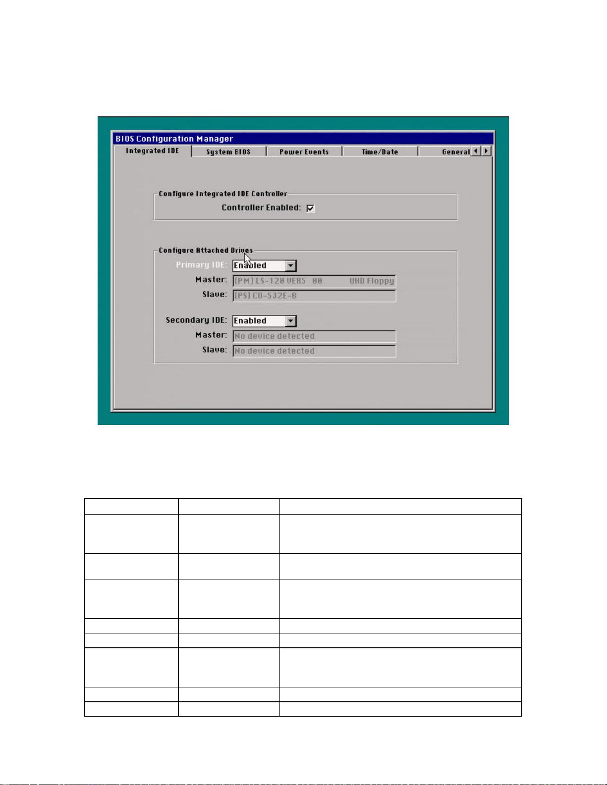
3.7 Integrated IDE Tab
hp workstation i2000 owner’s guide
Figure 15. Integrated IDE Tab Example
Table 11. Description of the Integrated IDE Tab
Feature Options Description
Controller Enabled
Spin Delay 0–60 seconds
Primary IDE
Master (Primary IDE) No options Reports the type of connected IDE device.
Slave (Primary IDE) No options Reports the type of connected IDE device.
Secondary IDE
Master (Secondary IDE) No options Reports the type of connected IDE device.
Slave (Secondary IDE) No options Reports the type of connected IDE device.
Enabled (default)
Disabled
(0 seconds is default)
Enabled (default)
Disabled
Enabled (default)
Disabled
Disabled will disable the dual-channel IDE controller. This option
will prevent the IDE controller from using system resources.
Enabled will enable the dual-channel IDE controller.
Selects the hard disk drive pre-delay. Causes the BIOS to insert a
delay before attempting to detect IDE drives in the system.
Enabled automatically sets the values for the LBA mode, transfer
mode, and Ultra DMA settings.
Disable will disable the primary channel.
Enabled automatically sets the values for the LBA mode, transfer
mode, and Ultra DMA settings.
Disable will disable the secondary channel.
53
Page 54
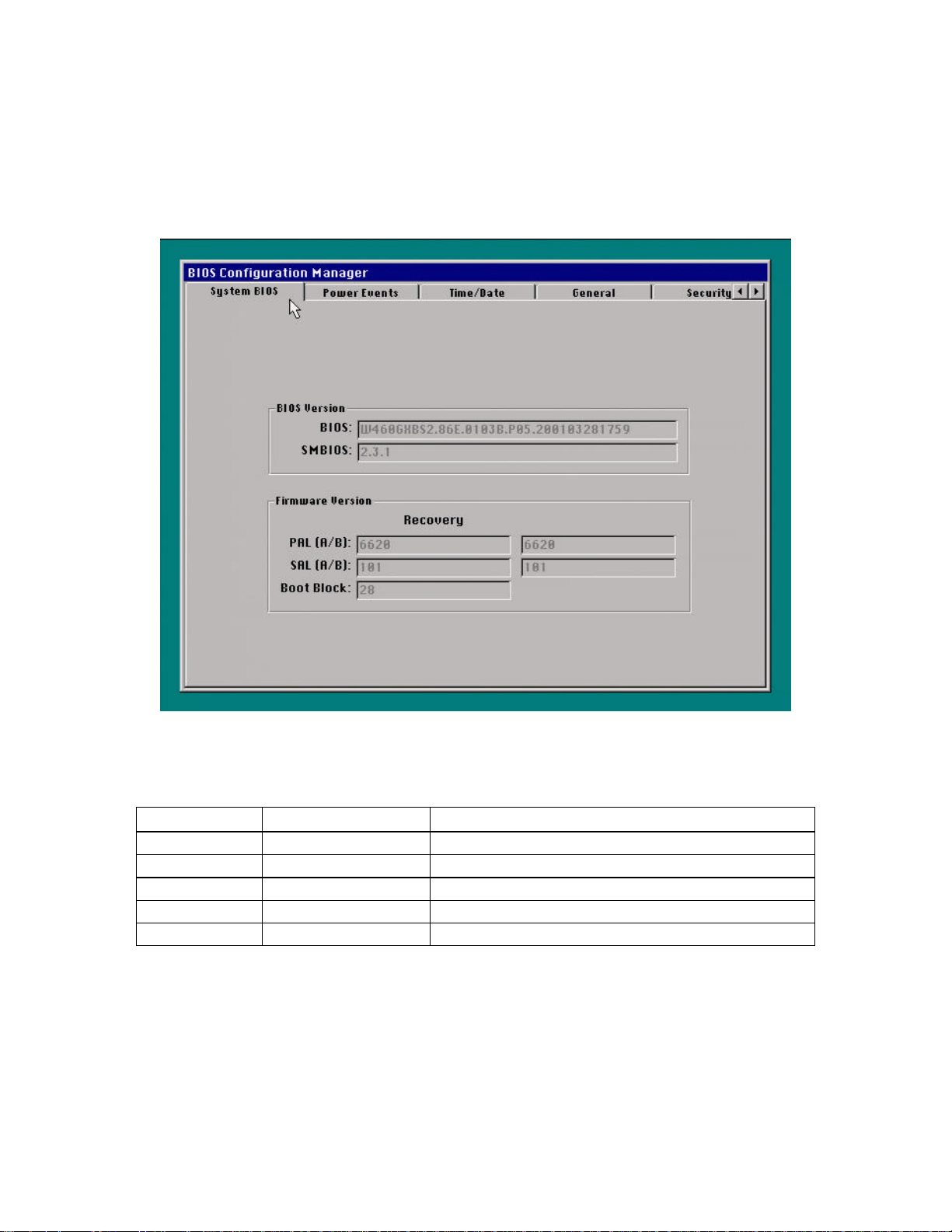
hp workstation i2000 owner’s guide
3.8 System BIOS Tab
Figure 16. System BIOS Tab Example
Table 12. Description of the System BIOS Tab
Feature Options Description
BIOS Version No options Displays the BIOS version.
SMBIOS Version No options Displays the System Management BIOS (SMBIOS) version.
PAL A/B Version No options Displays the Platform Abstraction Layer (PAL) version.
SAL A/B Version No options Displays the Software Abstractions Layer (SAL) version.
Boot Block No options Displays the Boot Block version.
54
Page 55
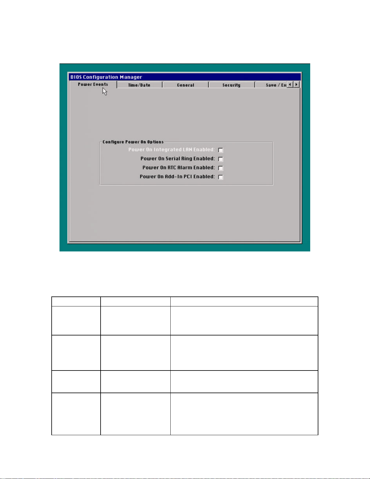
3.9 Power Events Tab
hp workstation i2000 owner’s guide
Figure 17. Power Events Tab Example
Table 13. Description of the Power Events Tab
Feature Options Description
Power On
Integrated LAN
Enabled
Power On Serial
Ring Enabled
Power On RTC
Alarm Enabled
Power On Add-In
PCI (PME) Enabled
Enabled
Disabled (default)
Enabled
Disabled (default)
Enabled
Disabled (default)
Enabled
Disabled (default)
Choose this option to enable Wake on LAN from ACPI sleep state
5, or from the normal off state in non-ACPI operating systems.
The default is disabled (the system will remain off). This option
has no effect on the wake events in ACPI sleep state 1.
Choose this option to enable wake on ring for external modems
connected to the serial port from ACPI sleep state 5, or from the
normal off state in non-ACPI operating systems. The default is
disabled (the system will remain off). This option has no effect on
the wake events in ACPI sleep state 1.
Choose this option to wake-up the system on an RTC Alarm. The
default is disabled (the system will remain off). This option has no
effect on the wake events in ACPI sleep state 1.
Choose this option to enable wake on PCI PME (Power
Management Event) for PCI modems or other PCI devices from
ACPI sleep state 5, or from the normal off state in non-ACPI
operating systems. The default is disabled (the system will remain
off). This option has no effect on the wake events in ACPI sleep
state 1.
55
Page 56
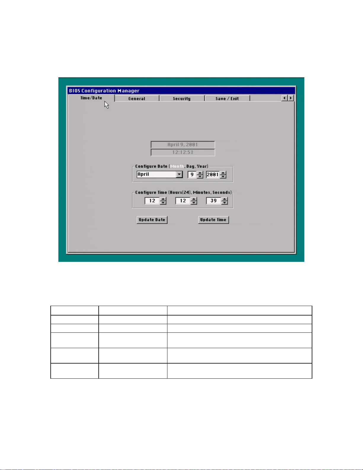
hp workstation i2000 owner’s guide
3.10 Time/Date Tab
Figure 18. Time/Date Tab Example
Figure 19. Description of the Time/Date Tab
Feature Options Description
Date No options Displays the current date.
Time No options Displays the current time (using 24-hour clock).
Month, Day, Year January - December, 1–31,
1980–2099
Hours, Minutes,
Seconds
Update Date/Update
Time
0–23, 0–59, 0–59 Specifies the current time.
Buttons Sets the date or time.
Specifies the current date.
56
Page 57
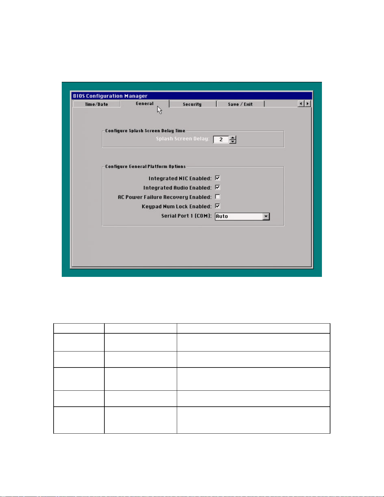
3.11 General Tab
hp workstation i2000 owner’s guide
Figure 20. General Tab Example
Table 14. Description of the General Tab
Feature Options Description
Splash Screen
Delay
Integrated Audio
Enabled
AC Power Failure
Recovery
Keypad Num Lock
Serial Port 1 (COM)
2–30 seconds
(10 seconds is default)
Enabled (default)
Disabled
Off (default)
On
On (default)
Off
Auto (default)
COM1
Disabled
Specifies the number of seconds to display the start-up screen
before automatically booting the operating system.
Enables or disables the on-board audio.
Specifies the response after an AC power failure. Choose Off to
keep the system off after AC power is restored. Choose On to
power-on the system after AC power is restored.
Specifies the power-on state of the Num Lock feature on the
numeric keypad of the keyboard.
Specifies the resources assigned for Serial Port 1.
57
Page 58
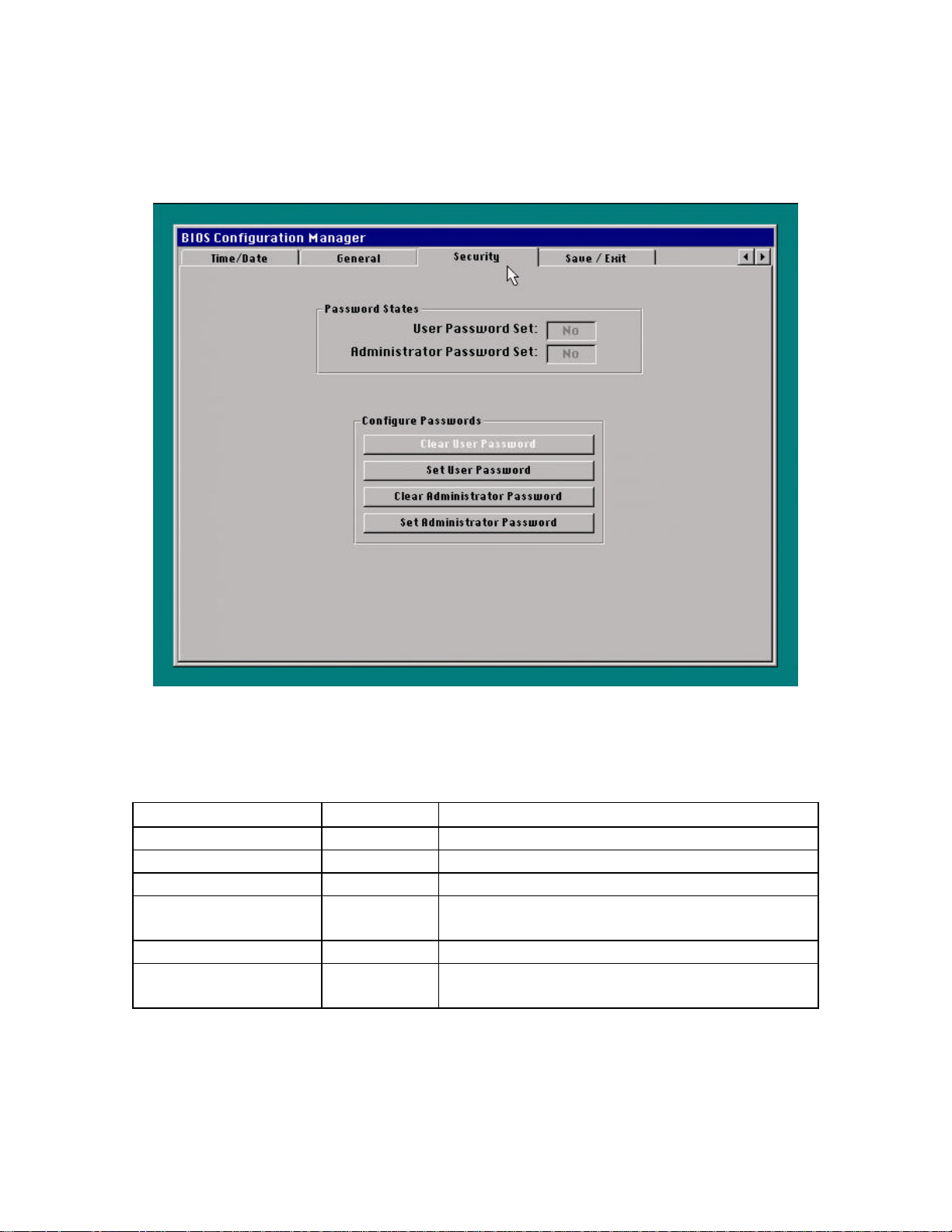
hp workstation i2000 owner’s guide
3.12 Security Tab
Figure 21. Security Tab Example
Table 15. Description of the Security Tab
Feature Options Description
User Password Set No options Reports if the User Password is set.
Administrator Password Set No options Reports if the Administrator Password is set.
Clear User Password Button Clears the User Password.
Set User Password Button Specifies the User Password.
The User Password can be up to 15 characters long.
Clear Administrator Password Button Clears the Administrator Password.
Set Administrator Password Button Specifies the Administrator Password.
The Administrator Password can be up to 15 characters long.
58
Page 59
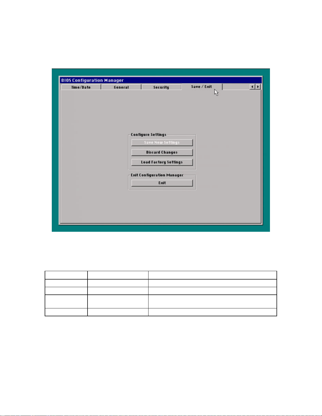
3.13 Save/Exit Tab
hp workstation i2000 owner’s guide
Figure 22. Save/Exit Tab
Table 16. Description of the Save/Exit Tab
Feature Options Description
Save New Settings Button Saves the changes in Flash memory.
Discard Changes Button Discards any changes made in Configuration Manager.
Load Factory
Settings
Exit Button Exits Configuration Manager.
Button Loads the factory default values for all the Configuration Manager
options.
59
Page 60
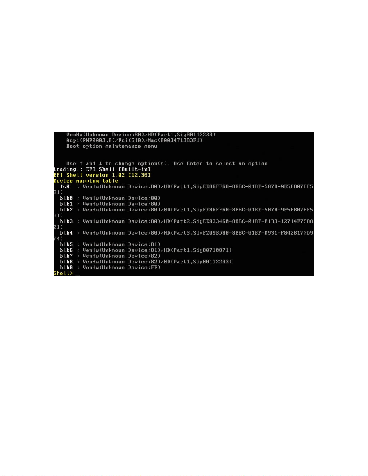
hp workstation i2000 owner’s guide
3.14 Using the EFI Shell and Boot Manager
1. Turn the power on, or restart the system.
2. Choose Boot OS from the Splash Screen or wait without making a choice (the
BIOS will boot the EFI Shell if you do not choose Enter Setup).
3. If only the User Password is set, you must enter the User Password. If both the
User and Administrator Passwords are set, you can enter either password.
4. The system boot manager will display similar to what is shown in Figure 23
Figure 23. EFI Boot Manager Prompt
5. Selecting the EFI shell option displays the device-mapping table and launches the
EFI command mode as shown in Figure 24.
60
Page 61
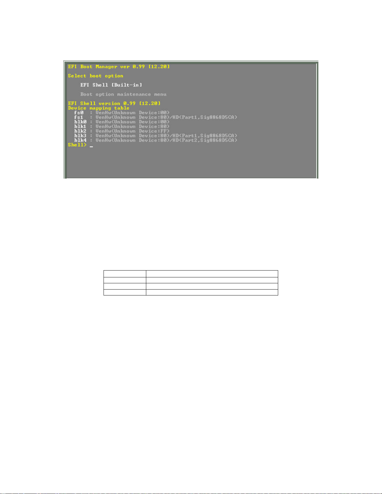
hp workstation i2000 owner’s guide
Figure 24. EFI Shell Command Mode
/ NOTE
Devices displayed in Figure 24 will change based on the various configurations.
Refer to Table 17 for device ID descriptions.
Table 17. Device ID Descriptions
Device ID Description
Device:00 Indicates an LS-120 drive
Device:8x Indicates a hard drive
Device:FF Indicates a CD-ROM drive
3.14.1 EFI Shell Commands
The EFI shell command descriptions are available at the EFI shell. Typing “help” at the
EFI prompt displays a list of EFI Shell commands with brief descriptions.
/ NOTE
If a –b option is used after typing a command (i.e., help –b) the list will scroll one(1) screen at a time.
61
Page 62
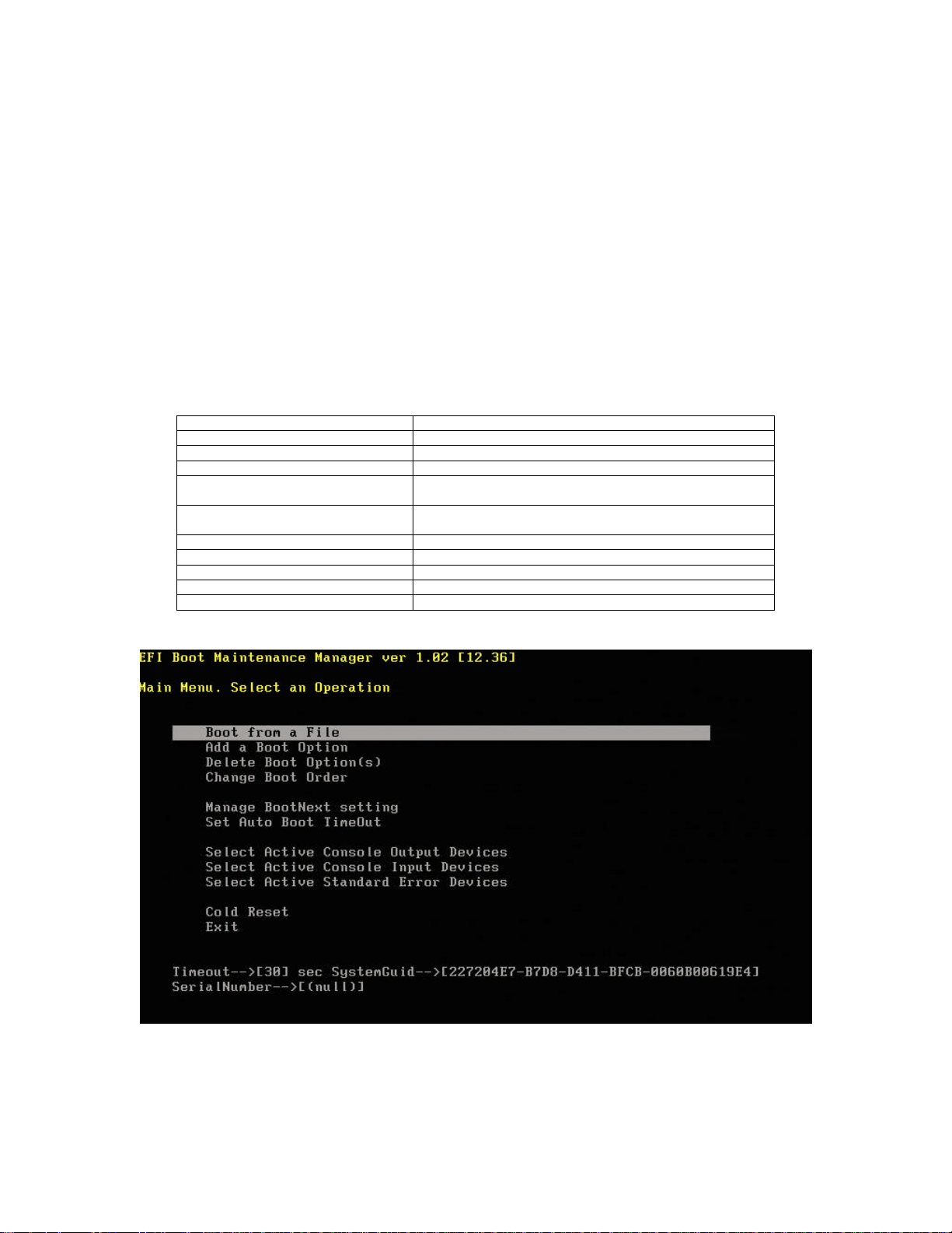
hp workstation i2000 owner’s guide
3.15 Boot Option Maintenance Menu
/ NOTE
For reference purposes, you should record the current settings in Appendix B.
When you make changes to the settings, update this record.
The boot option maintenance menu is organized into a set of menu options allowing you
to select how your system boots. Table 18 summarizes the options.
Table 18. Boot Option Maintenance Menu Summary
Boot from a File Allows browsing for a boot file.
Add Boot Option Adds new boot option file to Select Boot Option menu.
Delete Boot Option(s) Removes boot option file from Select Boot Option menu.
Change Boot Order Changes order of option in Select Boot Option menu.
Manage Boot Next Setting Sets or resets the option to which the system will automatically
Set Auto Boot Time Out Sets time delay before the system auto boots to the item
Select Active Console Output Devices Allows output to be directed to selected options.
Select Active Console Input Devices Allows input to be directed from selected options.
Select Active Standard Error Devices Selects devices where errors are reported.
Cold Reset Cold reboot of system.
Exit Returns to EFI Select Boot Option Menu mode.
boot on the next reboot.
selected in the BootNext option.
Figure 25. EFI Boot Maintenance Manager Main Menu
62
Page 63
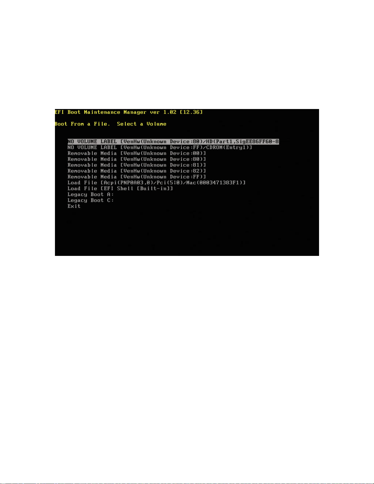
hp workstation i2000 owner’s guide
3.15.1 Boot From a File
Selecting Boot from a File allows you to browse for a boot file. Figure 27 shows a Boot
from a File screen.
Figure 26. Boot From File Browser
63
Page 64
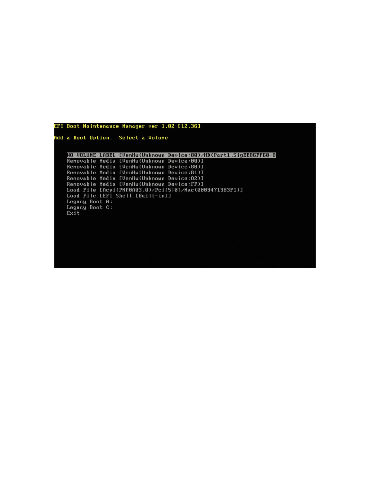
hp workstation i2000 owner’s guide
3.15.2 Add A Boot Option
Selecting Add a Boot Option on the main menu allows new Boot Option information to
be added to the EFI Shell. Use the following steps to add a Boot Option.
1. Select the device where the boot file is located (refer to Figure 28).
2. Select the file within the device.
Figure 27. Add Boot Option
3. Enter the file description at the prompt (refer to Figure 29).
4. Type ‘u’ or ‘U’ to select Unicode and press Enter.
5. Save the changes once the new information has been added.
64
Page 65
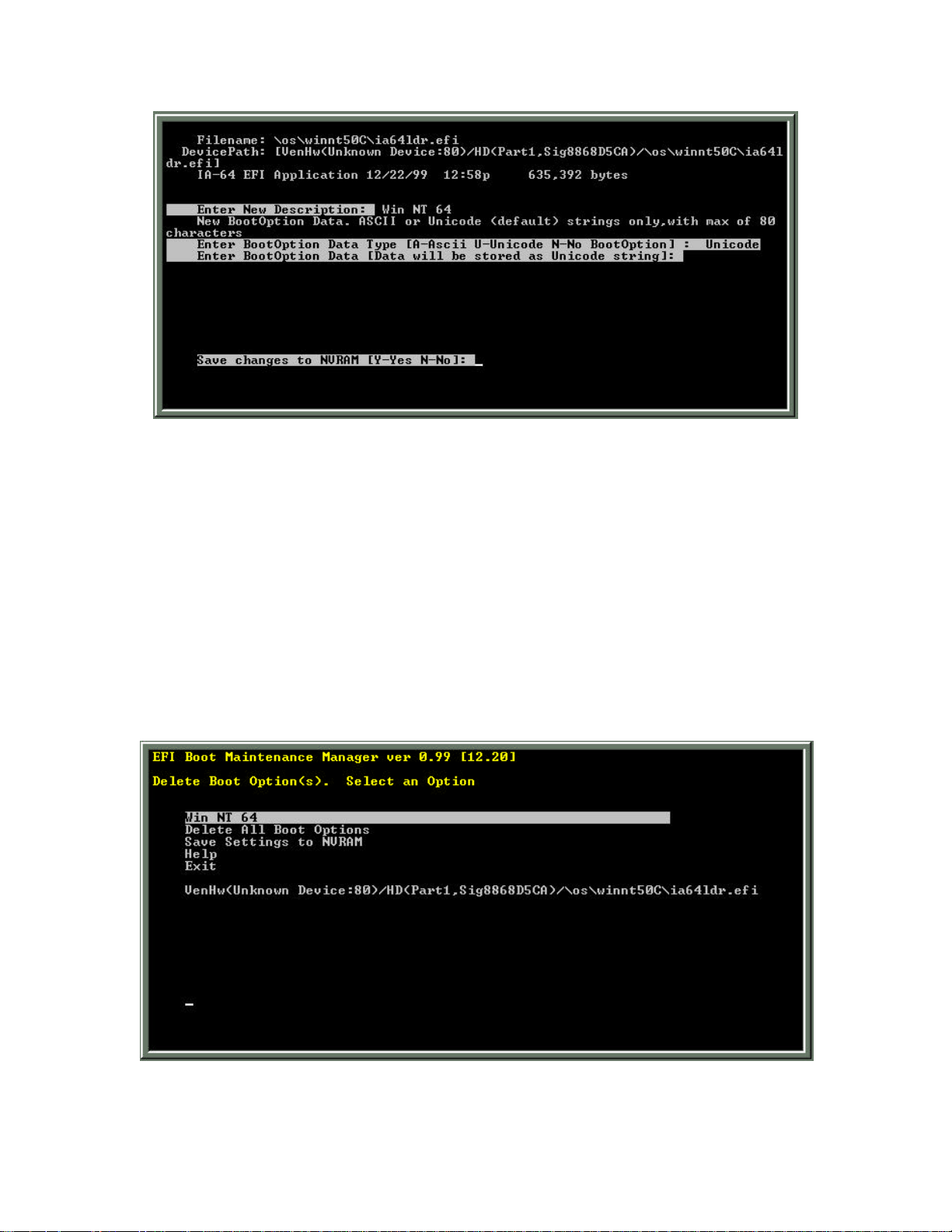
hp workstation i2000 owner’s guide
Figure 28. Add Boot Option Details
3.15.3 Delete Boot Option(s)
The Delete Boot Option(s) selection on the main menu allows you to delete a boot
option. To delete an option, highlight that option using arrow keys and press Enter. You
may also highlight an option and press ‘d’ or ‘D’ on your keyboard. To confirm your
delete command, press ‘Y’ or ‘N’ at the prompt. To delete all the boot options, select
Delete All Boot Options from the menu. Save your changes before exiting. Refer to
Figure 30.
Figure 29. Delete Boot Option
65
Page 66
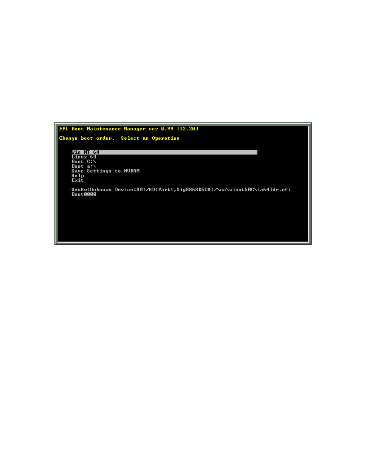
hp workstation i2000 owner’s guide
3.15.4 Changing the Boot Order
You may set the boot order by selecting Change Boot Order on the main menu. On the
Change Boot Order screen select a boot option using your arrow keys. Press ‘U’ or ‘u’
to move an option up the order chain and press ‘D’ or ‘d’ to move down the option order
chain. Save the changes before exiting. Refer to Figure 31.
Figure 30. Change Boot Option Menu Order
66
Page 67
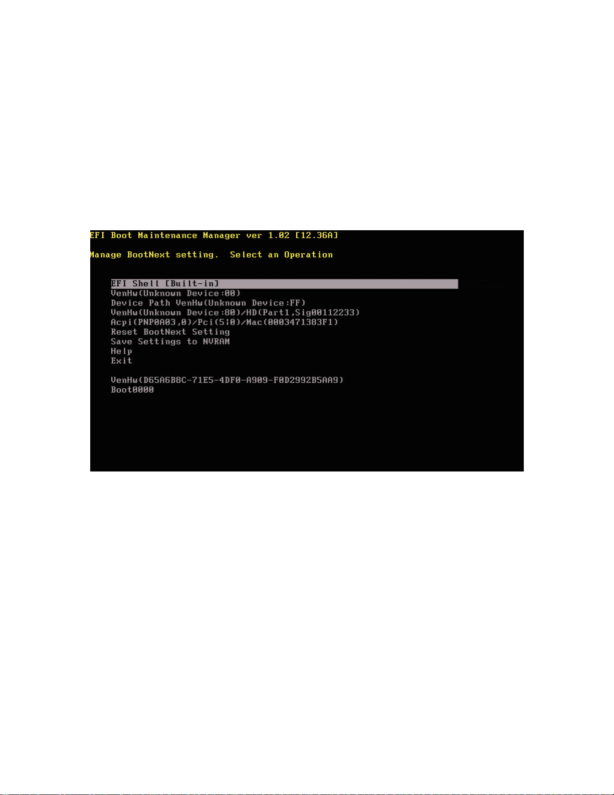
hp workstation i2000 owner’s guide
3.15.5 Manage BootNext Setting
Selecting the Manage BootNext Setting on the main menu allows you to set or reset
allowing the system to automatically boot on the next reboot cycle. At the BootNext
Setting screen select a boot option using your arrow keys. Press Enter, ‘b’, or ‘B’ to
designate this option as BootNext. To remove a BootNext setting, select Reset
BootNext Setting, or press ‘r’, or ‘R’ when the option is selected. Save the settings
before exiting. Refer to Figure 32.
Figure 31. BootNext Selection
67
Page 68
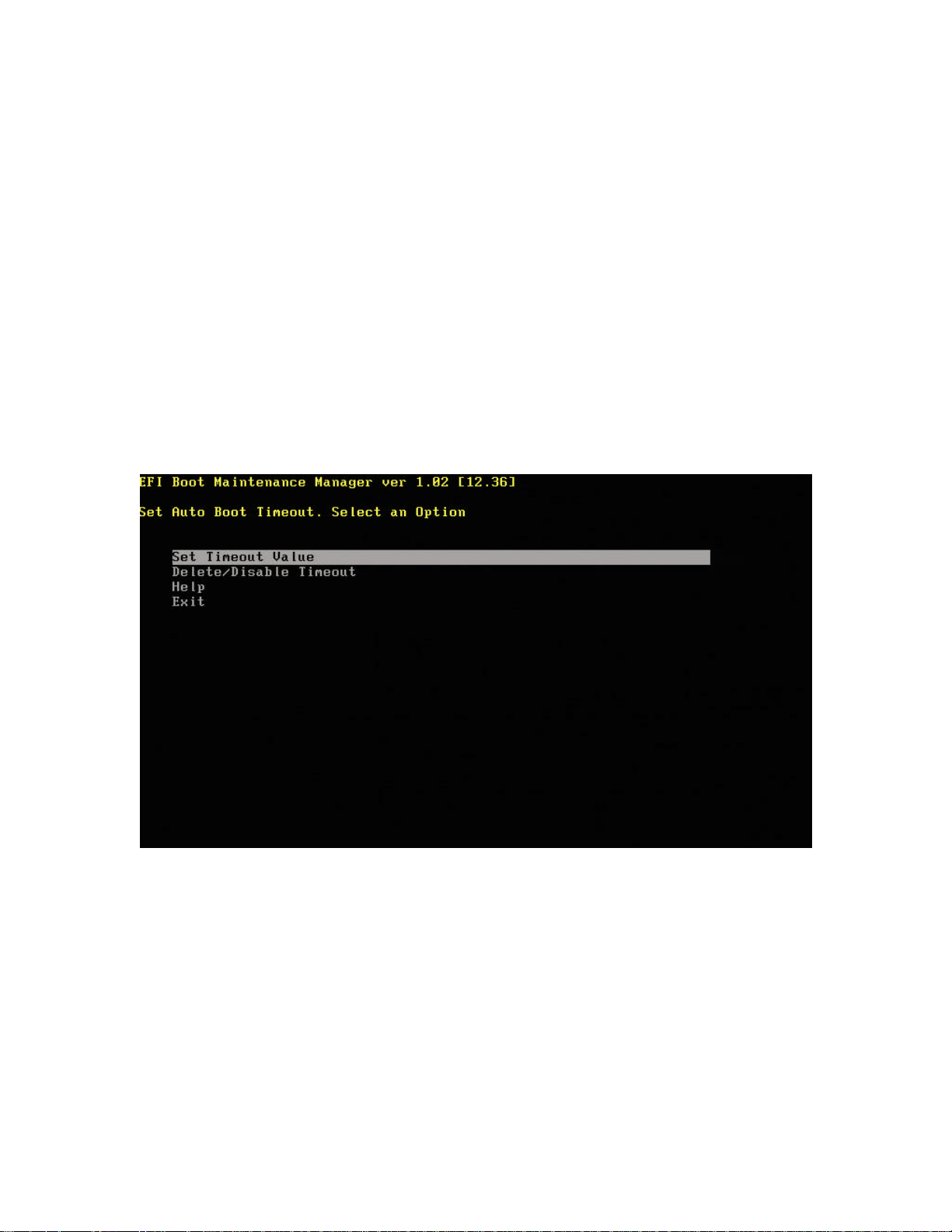
hp workstation i2000 owner’s guide
3.15.6 Set Auto Boot Timeout
The Auto Boot Timeout selection on the main menu allows you to set the Timeout
Value before the OS automatically boots. Use the Set Timeout Value option to set the
time, in seconds, to boot the default OS. If a value of zero- (0) is specified, there is no
wait to boot the default OS. The following three- (3) choices are available to disable the
timeout variable:
1. Use the Delete/Disable Timeout menu option to delete the timeout variable.
2. Set the timeout value to be 65535 <0xFFFF>.
3. Press a key when the EFI is booting and the timeout count down is disabled.
The timeout value is saved when the Set Timeout Value menu option is selected. Refer
to Figure 33.
Figure 32. Auto Boot Time Delay
68
Page 69
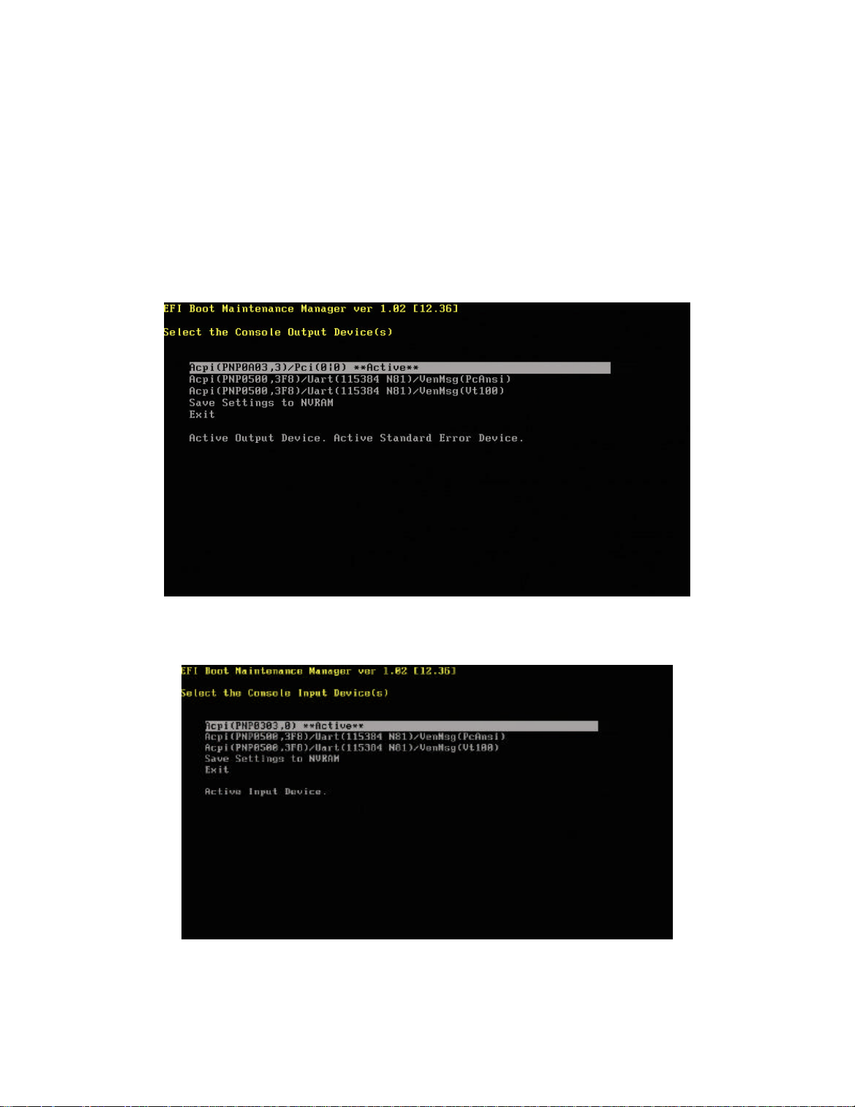
hp workstation i2000 owner’s guide
3.15.7 Select Active Console Output/Input Device
Choosing the Select Active Console Output Device option on the main menu allows
you to direct output to selected device options, while the Select Active Console Input
Device option allows input to be directed to selected device options. Use your arrow
keys to select your preferred device and press Enter to activate the option. Save your
settings before exiting. Refer to Figures 34 and 35.
Figure 33. Select Active Console Output Device
Figure 34. Select Active Console Input Devices
69
Page 70
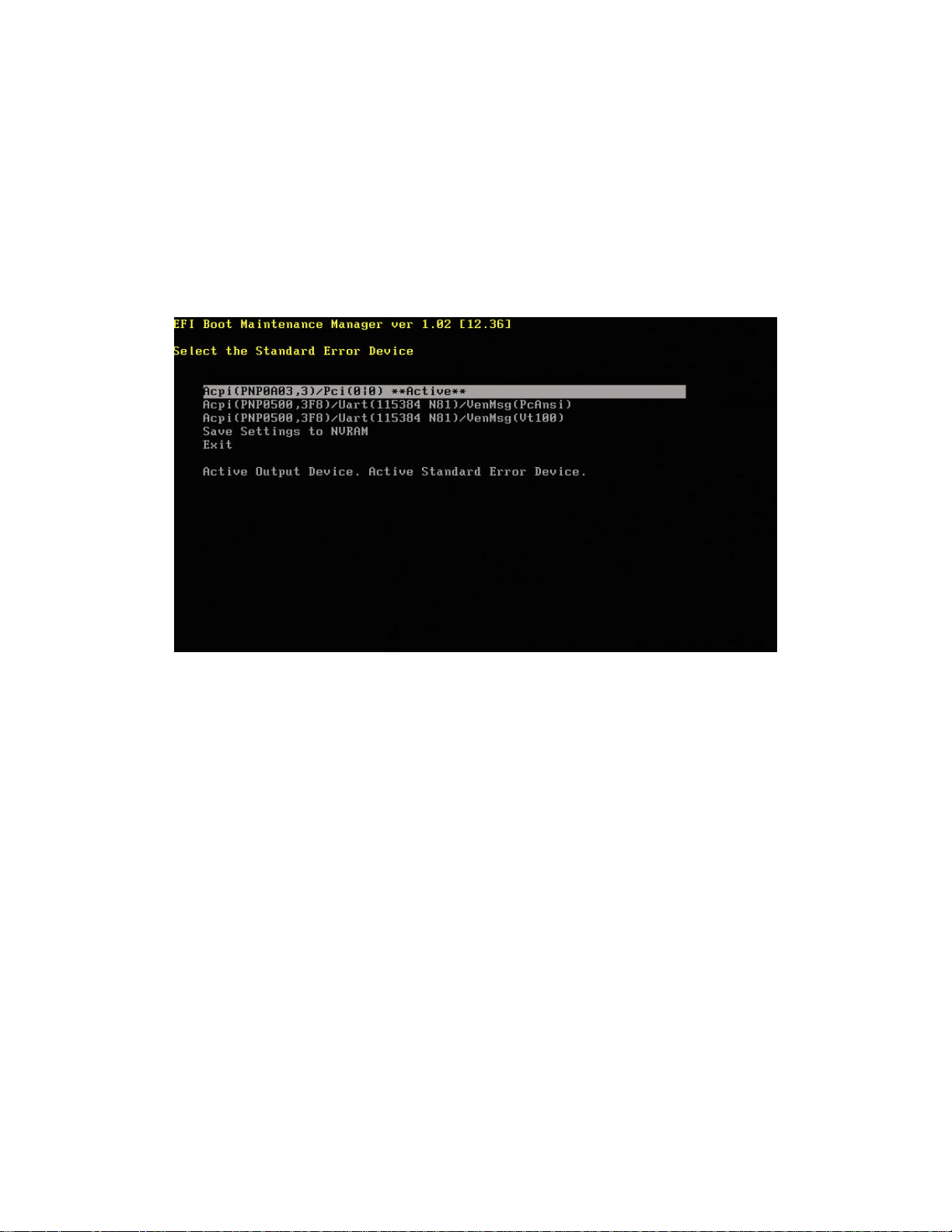
hp workstation i2000 owner’s guide
3.15.8 Select the Standard Error Device
Choosing the Select the Standard Error Device option on the main menu allows you to
select the device where errors are reported. Use your arrow keys to select your
preferred device and press Enter to activate the option. Save your settings before
exiting. Refer to Figure 36.
Figure 35. Select Active Standard Error Devices
3.15.9 Booting from a Network
To boot from a network use the following steps.
1. From the EFI Boot Manager Main Menu select Add a Boot Option.
2. Select the following option:
Removable Media [Acpi(PNPA03,0)/Pci(4¦0)/Mac(00XXXXXXXXXX)]
/ NOTE
The MAC address may vary with each board.
3. Enter a file description at the prompt (e.g., LAN or Network) and press Enter.
4. Save your settings.
5. Exit both the Add a Boot Option screen and the Boot Manager Main Menu
screen.
6. The EFI Boot Manager screen reflects your network boot option. Select this
option and press Enter to boot from the network.
70
Page 71

hp workstation i2000 owner’s guide
3.16 BIOS Flash Memory Organization
The Intel* E82802AC Firmware Hub (FWH) includes an 8 Mbit (1024 KB) symmetrical
flash memory device. There are four- (4) FWH devices located on the I/O board for a
total of 4 MB of flash memory. Internally, each device is grouped into eight- (8) 64-KB
blocks that are individually erasable, lockable, and unlockable with additional hardware
protection for the top block.
3.17 BIOS Upgrades
The following section describes how to upgrade the System BIOS.
3.17.1 Obtaining the BIOS Upgrade File
You can upgrade to a new version of the BIOS by using the latest image and the current
flash utility. The images and utilities are contained in a compressed, self-extractive
archive that contains all the files you need to upgrade the BIOS.
/ NOTE
Please review the instructions distributed with the BIOS files for last minute notes
before attempting a BIOS upgrade.
71
Page 72

hp workstation i2000 owner’s guide
3.17.2 Recording the Current BIOS Settings
/ NOTE
Do not skip step 2. You will need these settings to configure your computer at
the end of the upgrade procedure.
1. Boot the computer and choose the Enter Setup button.
2. Use the form in Appendix B: Configuration Manager Settings to record the
current settings in the Configuration Manager.
3.17.3 Upgrading the System BIOS
Use the BIOS Flash Upgrade Utility to upgrade your system BIOS by following the steps
outlined below:
1. Copy WFlash64.EFI and binary input file (bios103e.bin) to an LS120 disk.
2. Boot to the EFI shell.
3. Enter the following command line:
WFlash64 /P
4. When prompted for the required system reset press ‘y’ key to continue.
5. On the system reset boot to the EFI shell.
6. Enter the following command line and follow screen instructions:
WFlash64 bios103e.bin
7. Reboot the system after the update is completed.
72
Page 73
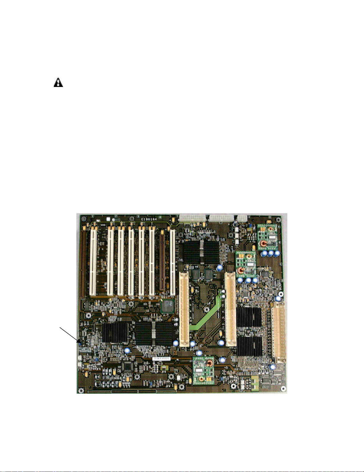
hp workstation i2000 owner’s guide
Configuration
3.17.4 Recovering the BIOS
WARNING
The inside of the chassis presents multiple risks of personal injury, including
risk of electrical shock, burns due to hot components, and lacerations due to
sharp edges! Refer to the Warnings section for important safety information.
Before opening the chassis, always turn the power off, unplug the power
cord from the wall outlet, disconnect any telephone lines or LAN
connections, and unplug all peripheral devices.
It is unlikely that anything will interrupt the BIOS upgrade. However, if an interruption
occurs, the BIOS could be damaged. To recover the BIOS, use the following procedure:
1. Copy the firmware image to an LS120 (Super Disk) with a filename of
bios103e.bin
2. Remove the chassis cover to gain access to the jumper.
3. Remove the Configuration Mode jumper (J29). Save the jumper.
J29
Mode Jumper
Figure 36. Location of Configuration Mode Jumper
73
Page 74

hp workstation i2000 owner’s guide
4. Reassemble your system.
5. Insert the disk in the LS120 drive and turn the power on.
6. Listen for the startup beep sequence (3-3-1-0).
7. The LS120 drive light will come on and in about 2-3 minutes will turn off.
8. At this point FLASH will be erased and programmed. Losing power at this point
will warrant a restart of the recovery process. This stage may take from 1-2
minutes.
9. When programming is complete (with SUCCESS) you will hear a beep
sequence of (3-3-3-0). Otherwise you will hear a beep code specific to the type
of failure.
10. Power down the system, restore the recovery jumper to the Normal setting
(pins 2-3).
NOTE: In the event of a failure during recovery, the beep sequence indicating the
type of failure will repeat until the system is powered down.
11. Reassemble the system.
12. Remove the Super Disk and reboot.
13. Choose Enter Setup.
14. Change the Configuration Manager settings to match your previous settings.
15. Save the changes and exit Configuration Manager.
NOTE: Additional information can be obtained from using the utility help option
from the EFI Shell:
WFlash64 /?
3.17.5 Language Support
Only English is supported on the i2000 workstations.
3.18 Boot Options
The default boot device can be set in the Boot Option Maintenance Menu (refer to Figure
36).
74
Page 75

hp workstation i2000 owner’s guide
4. Error and Informational Messages
4.1 Beep Codes
The BIOS uses a series of beeps on the internal speaker to alert the user to problems
during the boot process. In the following table, numbers indicate beeps; dashes indicate
a pause between beeps.
Table 19. BIOS Beep Codes
Beep
Code
1-1-5
2-1-1 Cannot recognize file system on media, must be FAT12 or FAT16
2-1-2 File not present on the disk
2-1-3 Recovery device not found
2-1-4 Recovery device initialization failure
3-1-1 Flash device initialization failure
3-1-2 Flash Update Operation Failed
3-1-3 Recovery device failed during a read operation
3-1-4 Flash device erase failure
3-1-5 Flash device programming failure
3-1-6 File Verify Operation (Checksum) Failed
3-1-7 Processor Patch Installation Failed
3-2-1 File Verify Operation (Invalid BIOS) Failed
3-2-2 File Verify Operation (Mismatched Platform BIOS) Failed
3-2-3 Boot Block Incompatible with BIOS
3-2-4 Flash Verify after Write Failed
3-3-1 Recovery started
3-3-3 Recovery completed successfully
Memory failure (all four rows have mismatched SPD data). Specification requires all four DIMMs of any
row must have the same SPD data.
Description
75
Page 76

hp workstation i2000 owner’s guide
4.2 BIOS Messages
4.2.1 Run-time Messages
Searching for Boot record from [device name]...OK
The BIOS is searching for, and found, a valid boot image. The device
name can be LS-120, HDD-0, HDD-1, CD-ROM, SCSI, or Network.
Searching for Boot record from [device name]...Not Found
The BIOS is searching for a valid boot image, but didn’t find one.
Drive Not Ready. Insert BOOT diskette in FS0:
The LS-120 drive is not physically connected, or the drive does not have
a diskette in the drive.
Invalid Boot Diskette
The diskette in the LS-120 drive contains an unformatted diskette.
Non-System disk or disk error. Replace and strike any key when ready.
The diskette in the LS-120 drive contains a formatted diskette, but not a
valid boot diskette.
4.2.2 Configuration Manager Messages
Password is incorrect!
The password you entered does not match the required password.
Password must be cleared before a new password can be set!
Use the Clear User Password or Clear Administrator Password button on
the Security Tab to clear the password before entering a new password.
Password cannot be zero length!
Passwords must contain one or more characters.
Password entries do not match!
The passwords entered in the Password Verification dialog do not match.
Enter the passwords again.
Altered settings have not been saved! Selecting “Continue” will discard changes.
Configuration settings have been changed but not saved. Press Continue
to exit without saving the changes, or Clear to return to Configuration
Manager.
76
Page 77

hp workstation i2000 owner’s guide
4.2.3 PXE Client Status and Error Messages
PXE-E05: Download buffer is smaller than requested file.
This error is displayed if the size of the requested file is larger than the allocated
download buffer.
PXE-E07: Network device error.
Network device could not be initialized or had some other unexpected failure.
PXE-E09: Could not allocate I/O buffers.
This error is displayed if there is not enough system memory to allocate network
I/O buffers.
PXE-E12: Could not detect network connection. Check cable.
Cable is not connected to NIC or something is wrong with NIC or cable.
PXE-E16: Valid PXE offer not received.
Client did not receive a valid PXE offer. This error is displayed for a number of
reasons:
• There are no DHCP or proxyDHCP servers that can receive the
clients DHCP discover packets.
• There are no DHCP or proxyDHCP servers that can transmit DHCP
offer packets to the client.
• The DHCP and/or proxyDHCP offer packets received by the client do
not contain enough information to complete a remote boot.
PXE-E21: Remote boot cancelled.
The user pressed <Esc> or <Ctrl+C> or selected a "Local Boot" option from the
remote boot menu.
This message is also displayed when a DHCP/proxyDHCP server sends down a
menu that auto-selects "Local Boot" and when a bootserver sends down a
bootstrap program that returns control to the PXE LoadFile protocol.
PXE-E22: Client received an ICMP error from server.
An ICMP error was sent to the client by a PXE bootserver or M/TFTP server.
PXE-E23: Client received TFTP error from server.
A TFTP server sent a TFTP error packet to the client.
PXE-E98: <extra information about previous error code>
If available, extra error information will be displayed about the previous error
message.
PXE-E99: Unexpected network error: XXh
This error is displayed if an EFI status code is returned by the network drivers
that was not expected by the PXE LoadFile protocol.
77
Page 78

hp workstation i2000 owner’s guide
5. Working Inside the System
5.1 Tools and Supplies Needed
A list of suggested tools and supplies is given below. Observe all warnings and cautions
when accessing the system.
1. Phillips (cross-head) screwdriver (#2).
2. Small flat-bladed screwdriver.
3. Jumper-removal tool or needle-nosed pliers.
4. Anti-static wrist strap and conductive foam pad (recommended).
5. Torque driver (optional).
6. Pen or pencil.
7. Equipment log (found in Appendix B) to record the model and serial number of
the system, all installed options, and any other pertinent information specific to
the system.
CAUTION
Only technically qualified persons shall perform integration/servicing of this
chassis.
Follow these guidelines to meet and maintain safety and product regulatory
compliance when integrating this chassis.
Read and adhere to all of these instructions and the instructions supplied with this
assembly. If you do not follow these instructions, the UL listing and other
regulatory certifications will be void, and the product may be non-compliant with
regional product laws and regulations.
CAUTION
Before removing or installing the i2000 system board or any other system
component, observe all the safety guidelines for safety requirements and
precautions. Always follow the steps in the procedure in the correct order (i.e., as
written). Use Appendix B to record identification information about your computer.
When working on any i2000 system board, wear an anti-static wrist wrap and place
the board on a conductive foam pad.
78
Page 79

hp workstation i2000 owner’s guide
WARNINGS
The procedures in this section assume that you are familiar with the general
terminology associated with personal computers and with the safety
practices and regulatory compliance required for using and modifying
electronic equipment including, but not limited to the following:
Turn off system AC power by unplugging the AC power cord from the wall
outlet. Disconnect the computer from any telecommunications systems,
networks, and modems attached before performing any of the procedures
described in this section. Not doing so may cause personal injury or
equipment damage.
CAUTION
Electrostatic discharge (ESD) can damage components. Therefore, protect
against ESD by performing the procedures described in this section only at an
ESD workstation or by wearing an anti-static wrist wrap and attaching it to a metal
part of your computer’s chassis.
79
Page 80

hp workstation i2000 owner’s guide
80
Page 81
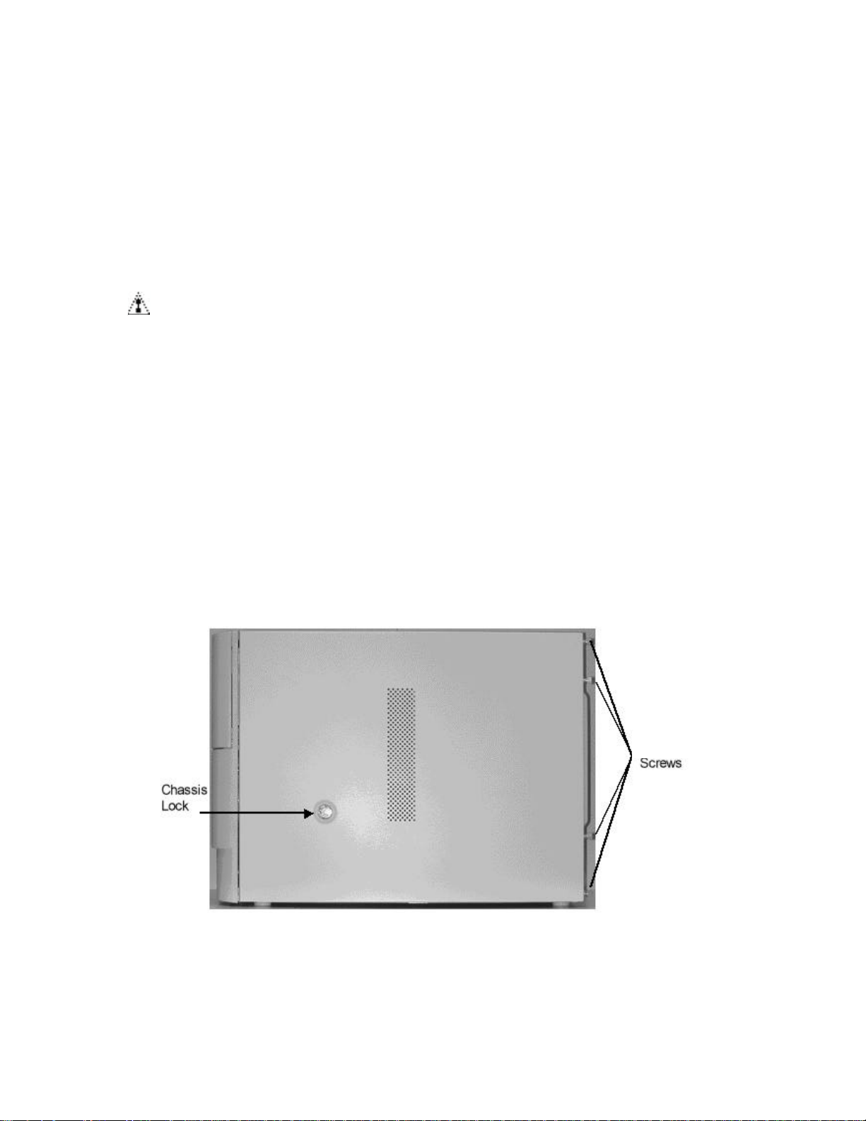
hp workstation i2000 owner’s guide
6. Accessing the System
/NOTE
Due to the weight of the workstation system (approximately 84 lbs.), care must
be taken when maneuvering the system during assembly and disassembly.
CAUTION
The DC push-button on/off switch on the system does not completely turn off
system AC power. To remove AC power from the system, you must unplug
each AC power cord from the wall outlet or power supply.
Before servicing, first identify the component(s) that must be added or removed from the
system. If replacing components, such as hard drives, CD-ROMs, or the LS-120 floppy
drive, the front bezel (large plastic section on the front of the system) must be removed
for access to the bays, as well as side access within the system. In cases not involving
the peripherals or front panel ports, the bezel can remain in place. Use the following
steps to access or open the system:
1. Starting with the system in an upright (normal) position, and resting on an antistatic surface, loosen the four- (4) Phillips-head screws from the rear (as shown
in Figure 38).
Figure 37. Removing the Four- (4) Chassis Screws
81
Page 82
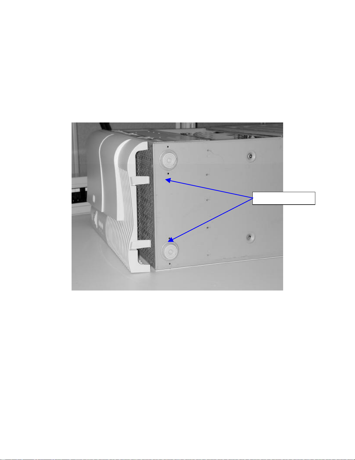
hp workstation i2000 owner’s guide
2. Carefully place the system on its side. The side containing the lock in the center
should be facing upwards.
3. Pull the system out from the work area and grasp the bottom inside of the bezel.
Locate the two- (2) bezel clips (as show in Figure 39) near the bottom of the
system and press in to disengage the bezel from the chassis sheet metal. Once
disengaged, gently pull the front bezel away from the system. There are four- (4)
interlock clips that disengage from the slots within the system chassis.
Bezel Interlock Clips
Figure 38. Bezel Interlock Clips
4. Remove the side cover by firmly pressing on the center of the panel and pushing,
forcing the panel to slide backwards toward the rear of the unit.
82
Page 83
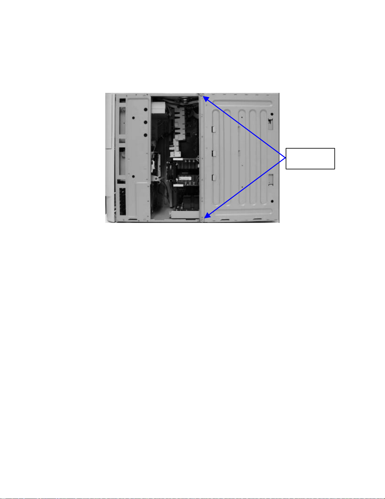
hp workstation i2000 owner’s guide
Power Supply
5. Once the side cover has been removed the system should appear (as shown in
Figure 40).
Door Screws
Figure 39. Internal System View after Side Door Removal
6. Remove the two- (2) Phillips-head screws from the power supply door and set
aside for later reinstallation.
83
Page 84
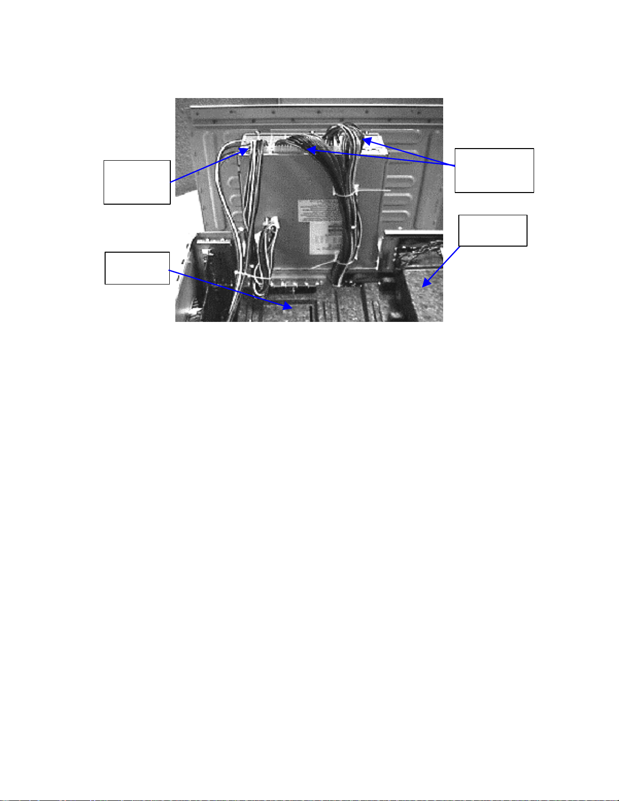
hp workstation i2000 owner’s guide
E-PAC
Peripheral
Baseboard
Baseboard
Power
Power
Harness
E-PAC
Harness
Processor
Figure 40. Power Supply Door in Opened Position
7. Open the power supply door (as shown in Figure 41) by pulling upwards and
allowing the door to swing outwards until the metal clip (near the top of the
system) is engaged with a "click". The power supply door is now locked into an
open position for system access.
8. Remove the baseboard E-PAC (black Styrofoam protective material as shown in
Figure 41).
84
Page 85
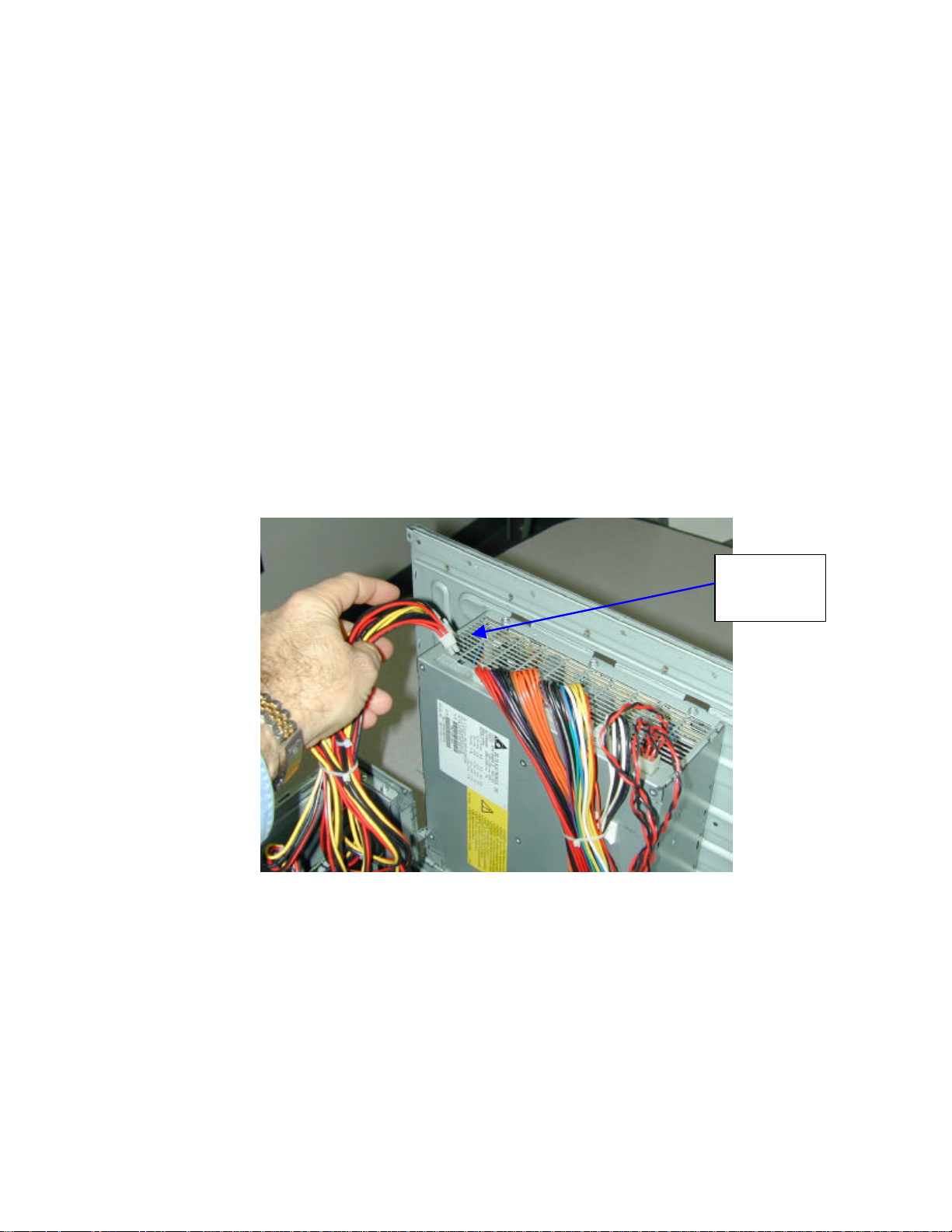
hp workstation i2000 owner’s guide
7. Removal of the System Components
7.1 Removal of the Power Harness
1. Locate and then remove the peripheral power supply harness from the main
power supply (as shown in Figure 42) in order to gain better access to the
system boards.
2. Lay the harness aside.
/NOTE
This step does not require the power harness to be disconnected from any
internal peripherals or to be completely removed from the system chassis.
Peripheral
Power
Harness
Figure 41. Peripheral Power Harness
85
Page 86
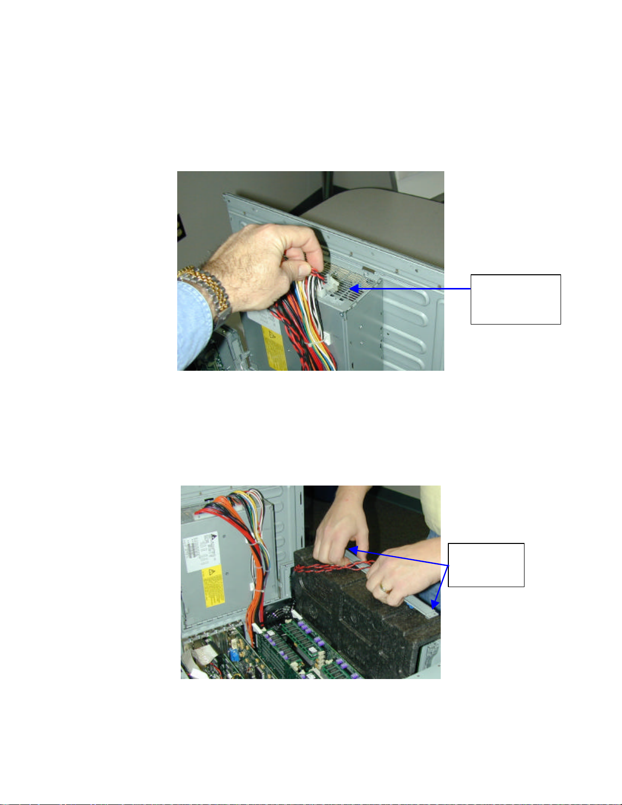
hp workstation i2000 owner’s guide
7.2 Removing the Processor Board
1. Locate and remove the processor Power Pod’s power harness from the main
power supply (shown in Figure 43).
Processor
Assembly
Power Harness
Figure 42. Processor Power Harness
2. Locate and remove the two- (2) screws securing the processor assembly to the
system chassis and set aside for later reinstallation. Remove the processor
assembly from the system chassis by lifting as shown in Figure 44. Place the
entire assembly aside on an anti-static surface.
Processor
Assembly
Screws
Figure 43. Processor Assembly
86
Page 87
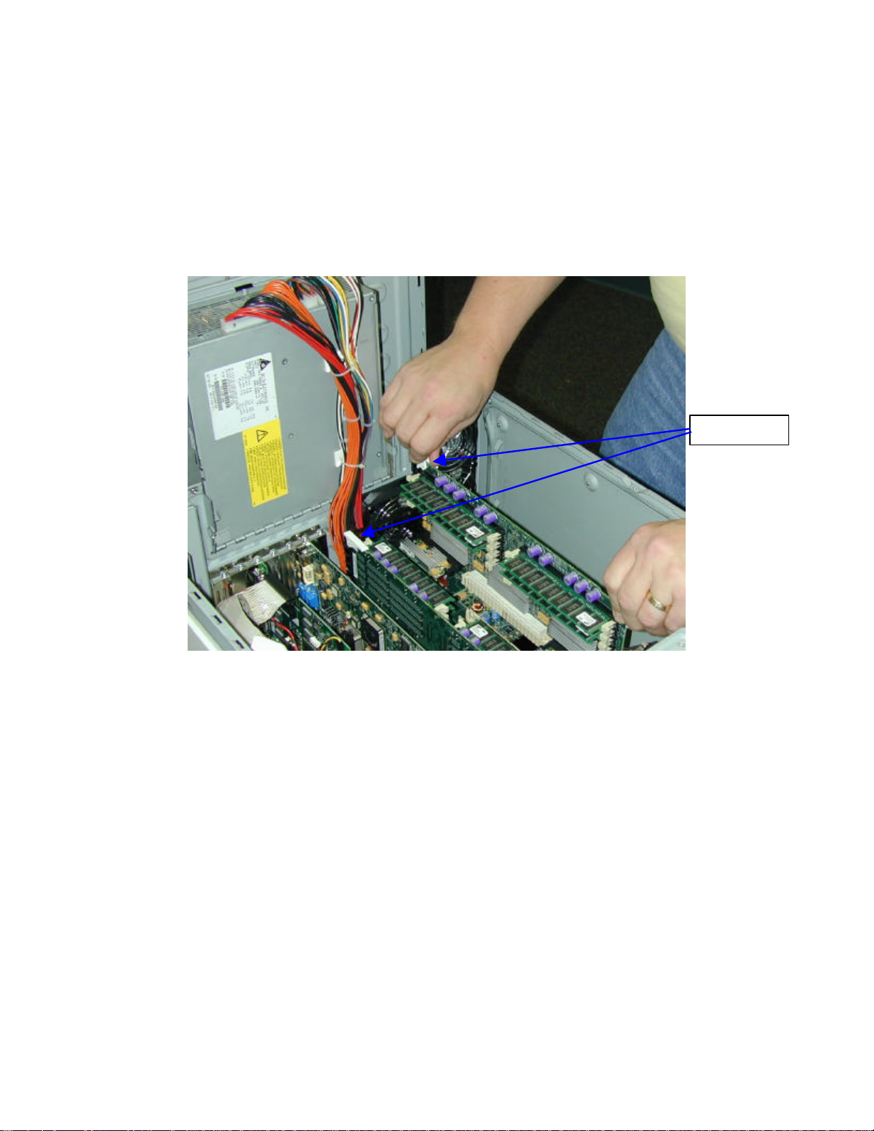
hp workstation i2000 owner’s guide
7.3 Removing Memory Boards
1. Use the white ejector tabs mounted on the top edges of the memory cards to
remove either memory card from the system. Refer to Figure 45.
Ejector tabs
Figure 44. Memory Cards
2. Place these cards aside on an anti-static surface.
7.4 Removing Adapter Cards
1. Before disconnecting cables from any board, note location, function and port
connections.
2. Locate the PCI or AGP card(s) to be removed.
3. Remove the rear panel retaining screw and lift the card from the system
connector slot using care not to angle the card.
4. Place these cards aside on an anti-static surface.
87
Page 88
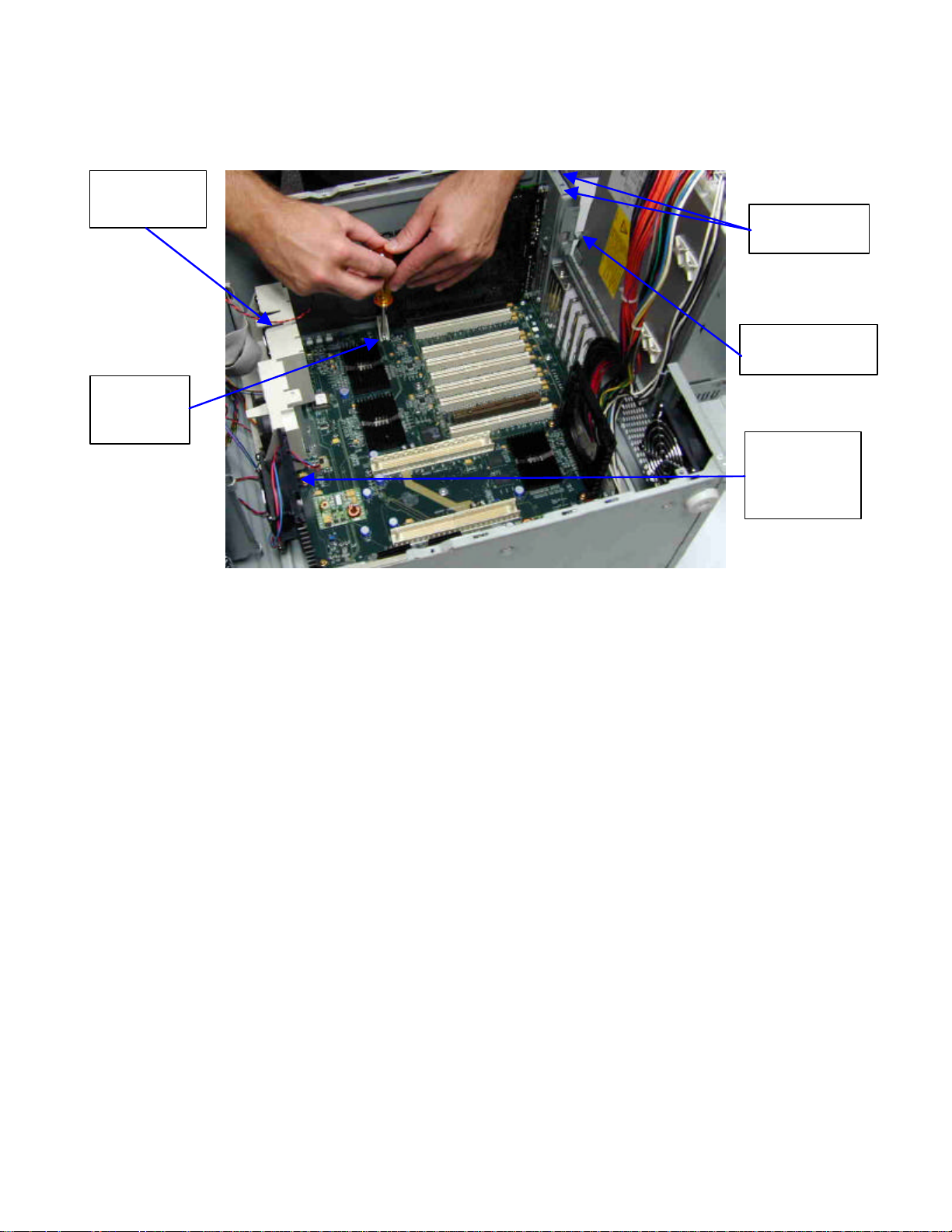
hp workstation i2000 owner’s guide
Fan
Card Guide
I/O Retaining
Screws
Rear I/O
Retaining Screw
I/O Card
Retaining
Foot
Memory
Card
Retention
Posts
Figure 45. Internal Component Locations
7.5 Removal of the I/O Board
1. Disconnect all I/O card cables and connectors.
2. Remove the two- (2) screws at the top of the I/O bracket located inside the
system.
3. Remove the screw holding the I/O bracket to the rear of the system (external).
Refer to Figure 46.
4. Remove the screw fastening the plastic retaining foot, at the front of the I/O
board, from the baseboard. Refer to Figure 46.
5. Place this card aside on an anti-static surface.
88
Page 89
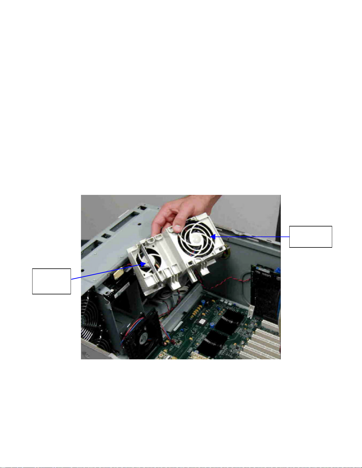
hp workstation i2000 owner’s guide
7.6 Removal of the Baseboard
1. Prior to removing the system baseboard, all board and cards described
previously must be removed.
2. Remove all fan power connectors from the baseboard.
3. Locate and remove the four- (4) screws (two- [2] each) from the memory card
retention posts. Refer to Figures 47 and 48.
4. Locate the fan card guide, refer to Figure 48 and remove the one- (1) screw
securing the module to the chassis. Apply pressure along the top of the card
guide (from the rear) pushing it inward (toward the baseboard) to disengage the
mounting clips located at the bottom.
/NOTE
The forward memory, card retention post has a cooling fan mounted to it. Do not
remove the fan from the retention post. Refer to Figure 47 and Figure 49.
Cooling
Fan for
AGP
I/O Cooling
Fan
Figure 46. Fan Card Guide
89
Page 90
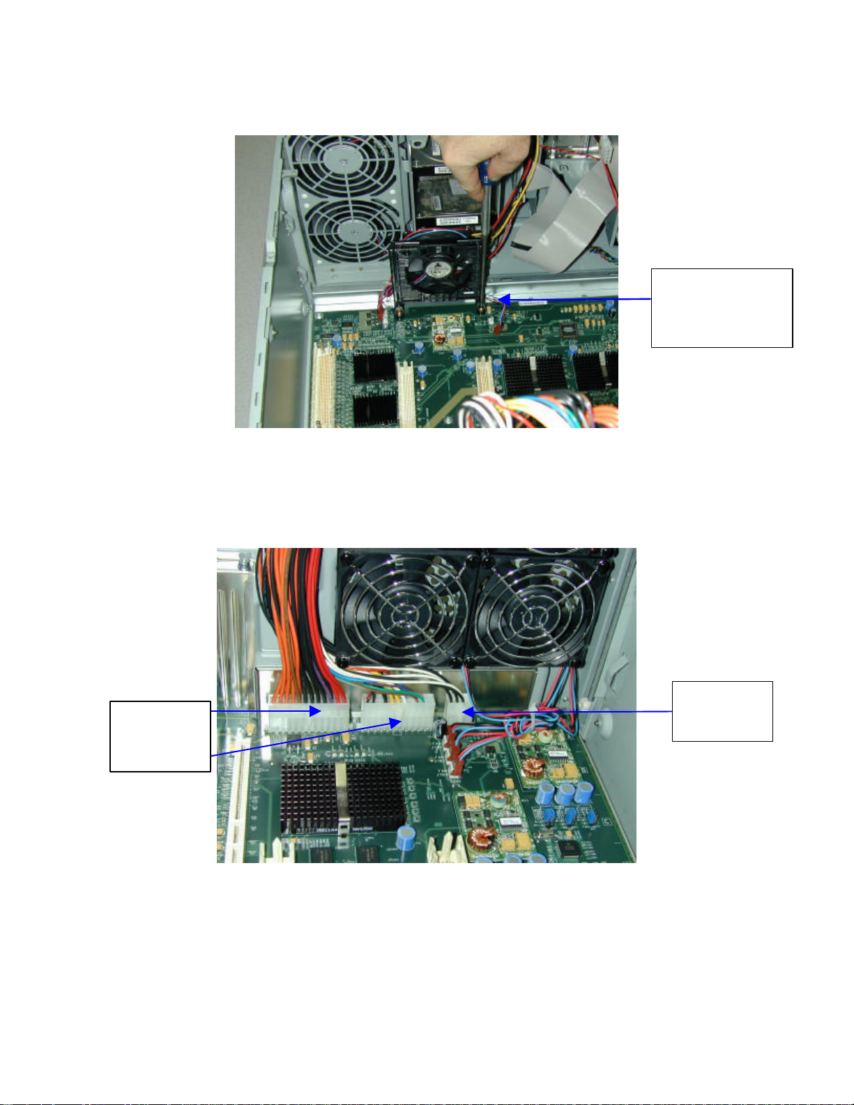
hp workstation i2000 owner’s guide
Forward Memory
Retention Post
(Contains Cooling
Fan)
Figure 47. Memory Card Retention Post (Front)
5. Remove the remaining three- (3) main power supply connectors from the rear of
the baseboard. Refer to Figure 49.
Power
Supply
Connectors
Power
Supply
Connector
Figure 48. Main Power Connection
6. Remove the eight- (8) remaining screws securing the baseboard to the chassis
and then remove the baseboard from the system chassis. Refer to Figure 50 for
mounting screw locations.
90
Page 91
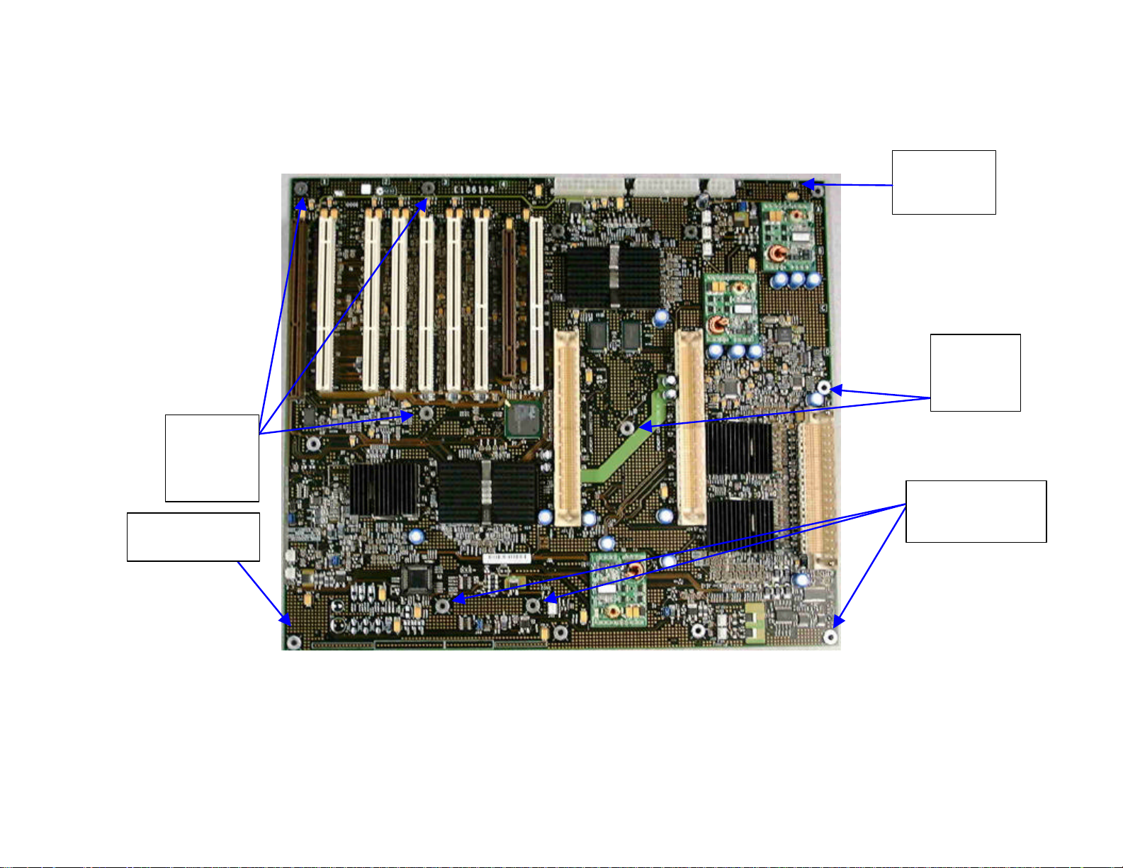
Baseboard
Baseboard
Mounting
Screws
1, 2 & 3
Baseboard
Alignment pin 2
hp workstation i2000 owner’s guide
Baseboard
Alignment
pin 1
Mounting
Screws
4 & 5
Baseboard
Mounting Screws
6, 7 & 8
Figure 49. Baseboard Mounting Screw Locations
91
Page 92
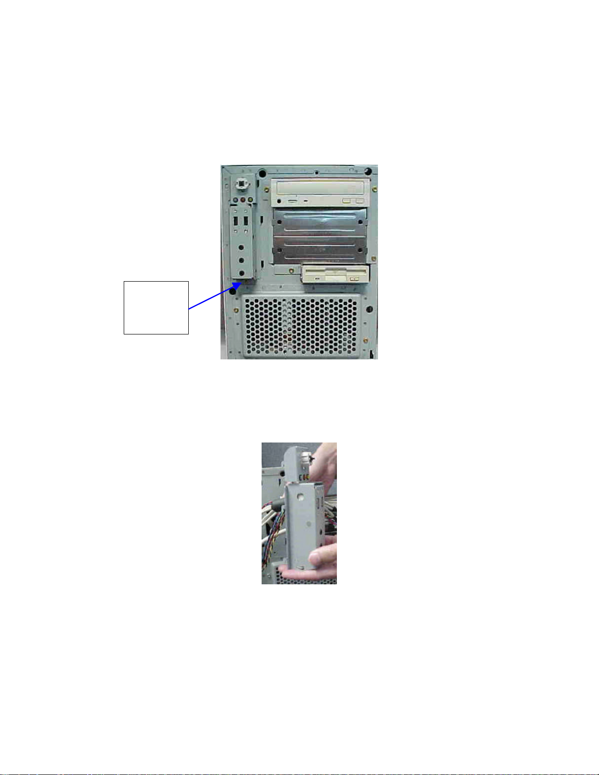
hp workstation i2000 owner’s guide
7.7 Removal of the Front Panel Assembly
1. Remove the Phillips-head screw from the bottom of the front panel assembly.
Refer to Figure 51.
Front
Panel
Assembly
Screw
Figure 50. Chassis Front With Bezel Removed
2. Lift the assembly upward and pull forward while feeding cables through from the
inside. Note the routing of the cable. Refer to Figure 52.
Figure 51. Front Panel Assembly
3. To reinstall, feed the power switch / audio and USB assembly cables through the
chassis where the prior cables were removed.
4. Reattach with the screw that was removed in step 1.
5. Reconnect the cables.
92
Page 93
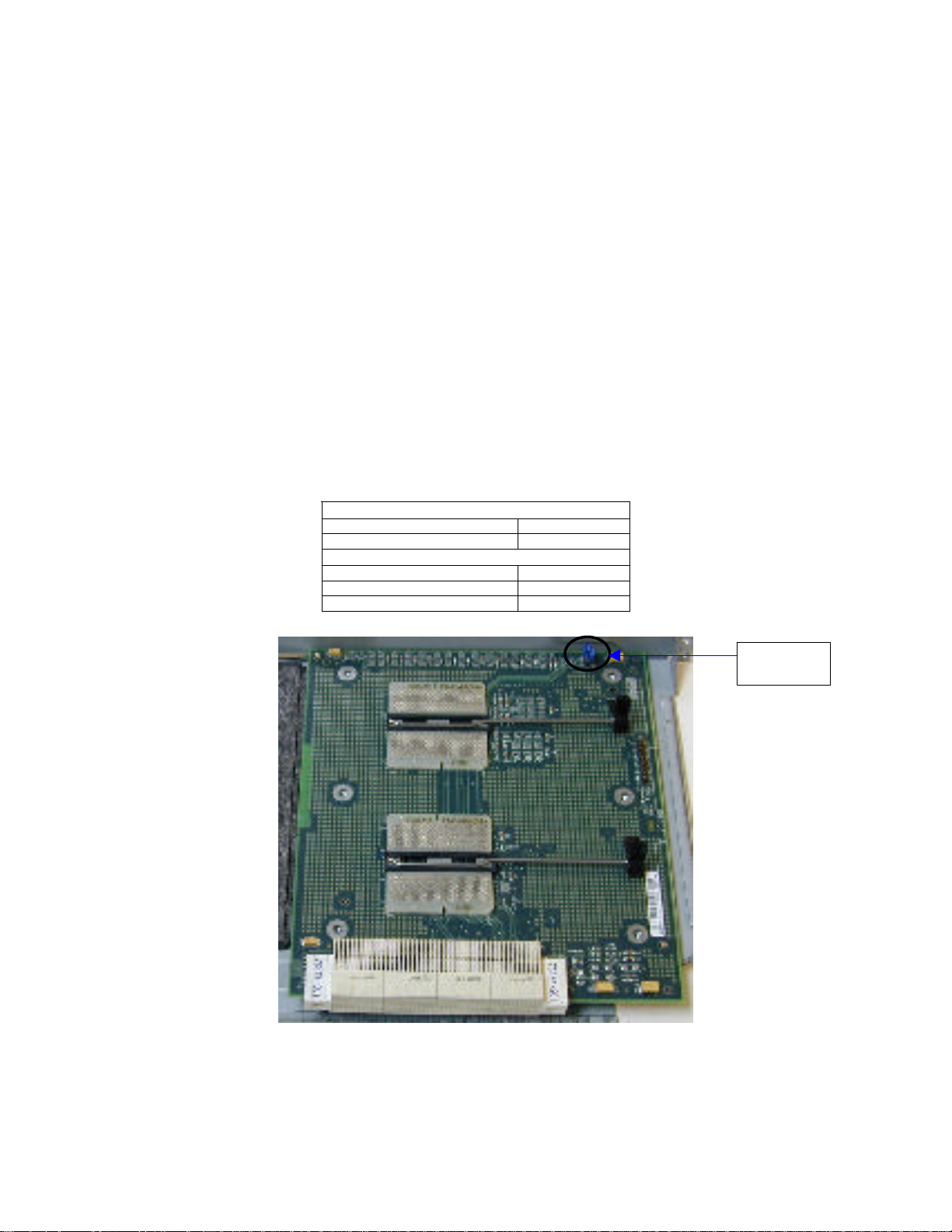
hp workstation i2000 owner’s guide
8. Installation of Upgrade Components
8.1 Verification of the Jumper Settings
The following section describes the jumper settings on the boards in the i2000 system.
The Processor Present jumper (J1) on the processor board (refer to Table 20)
configures the ITP scan chain for single or dual processor mode. The jumper should be
configured to match the number of processors in the system, but is on necessary for
functional performance.
8.1.1 Processor Jumpers
Table 20. Processor Present (J1)
Present (valid) 1-2*
Not Present (invalid) 2-3
Present 4-5
Not Present 5-6*
DEFAULT*
Single Processor Scan Chain
Dual Processor Scan Chain
Processor
Present (J1)
93
Page 94
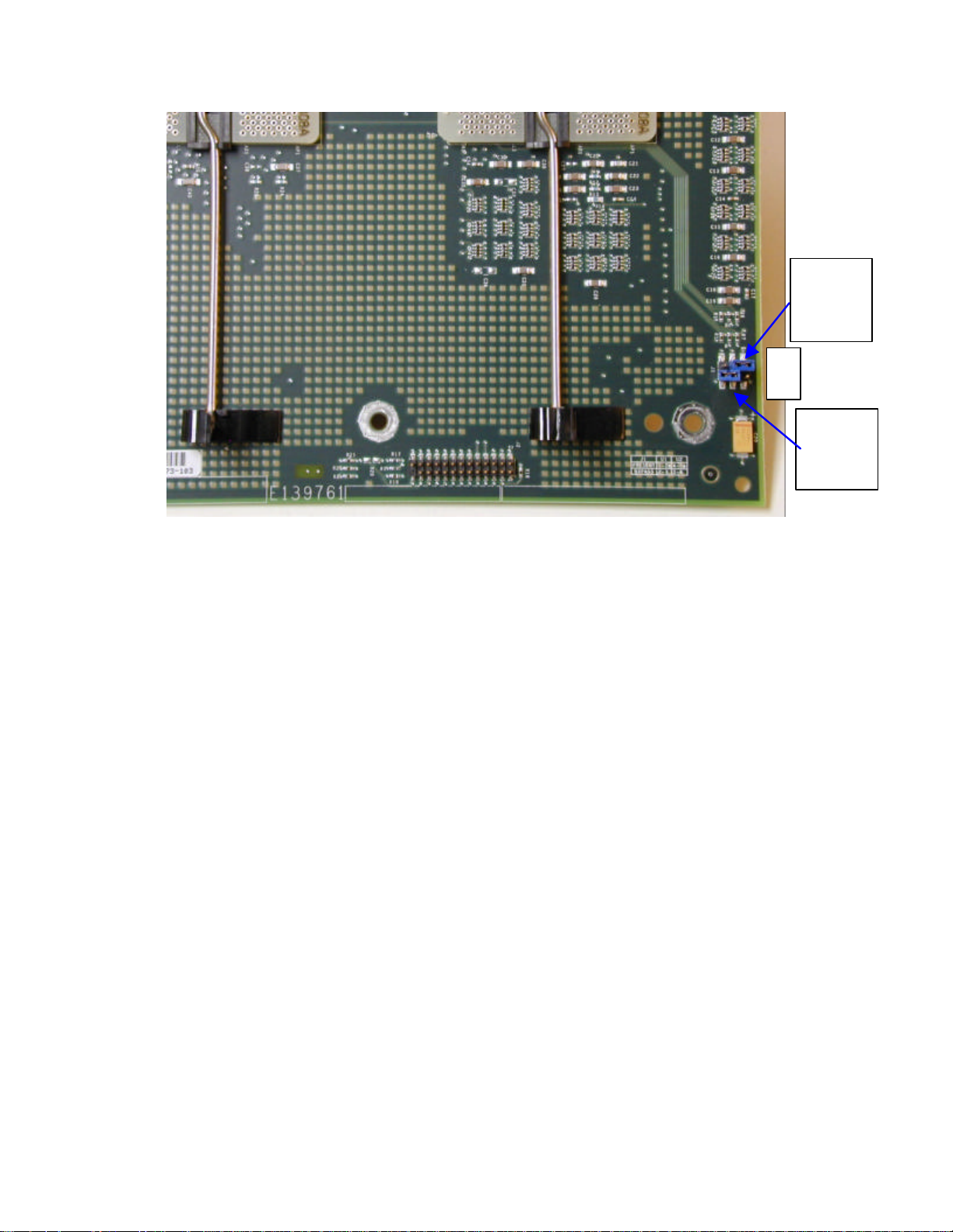
hp workstation i2000 owner’s guide
Position
Jumper
1-2
Position
Jumper
5-6
J1
321
654
J1
Figure 52. Processor Board Jumper Settings
94
Page 95
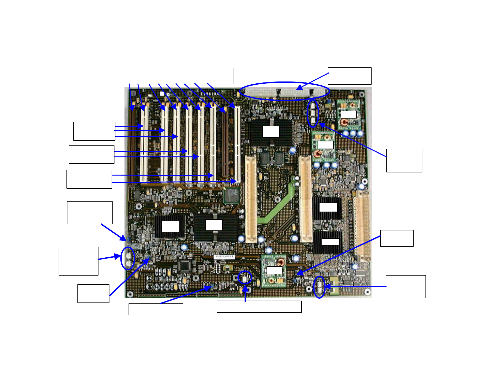
PCI Slot
I/O S2 1 2 3 4 5 AGP 6
WXB Bus 0
WXB Bus 1
PXB Bus 0
SAC
VRM
Forward Fan
Forward Fan
Memory Zone Fan Connector J46
VRM
VRM
8.1.2 Baseboard Jumper Settings
numbering scheme
hp workstation i2000 owner’s guide
Power Supply
Connectors
Slots S2, 1 & 2
Slots 3 & 4
3.3 volt
Slots 5 & 6
5 volt
J28 SMBUS
J29 Norm &
Override
Module
Connectors
J33, J36
J34 Fan
Control
3.3 volt
GXB
Rear Fan
Connectors
J5, J8, J11
SDC
WXB
J49 Fan Control
PXB
J47 Fan
Control
Connectors
J48, J50
Figure 53. Baseboard Jumpers and Connectors
95
Page 96

Table 21. Boot Jumper Header (J29)
NORM 1-2*
OVRD/CLRCMOS 2-3
RECOVERY No jumper
*DEFAULT
Table 22. FAN Thermal Control (J4, J47, J49, J34)
Variable Speed 1-2*
Full speed No jumper
*DEFAULT
Page 97
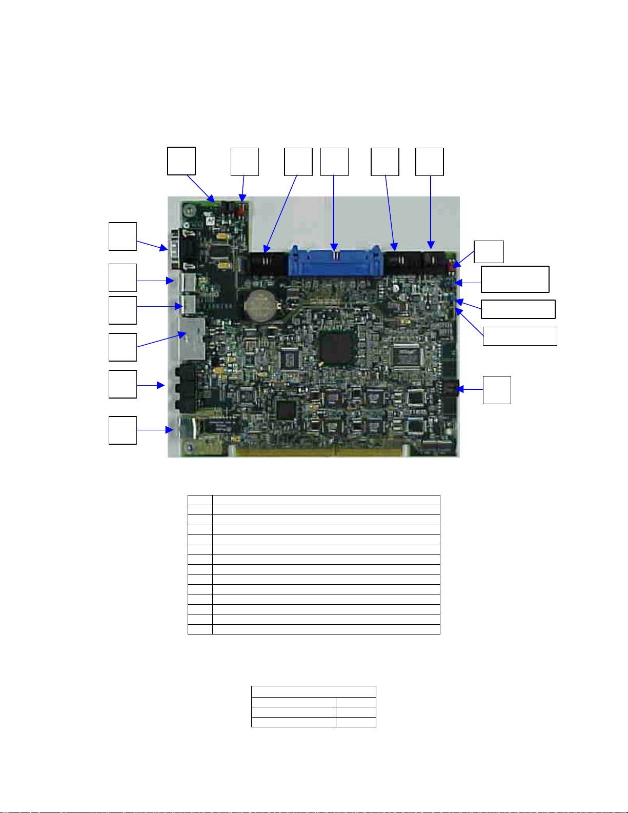
hp workstation i2000 owner’s guide
C D E A F G
L N
Block Lock
H
8.1.3 I/O Board Connectors and Jumpers
I J K
M
B
J8C3 Top
J8C4 Admin
J8C5 NMI
Figure 54. I/O Board Connectors and Jumper Settings
A. Serial Port Connector
B. PS/2 Mouse Connector
C. PS/2 Keyboard Connector
D. Two- (2) USB Connectors
E. Audio Connector
F. LAN (10/100 Mbps)
G. Speaker Connector
H. Chassis Intrusion Switch Connector
I. Front Panel Power switch & LED’s
J. IDE Connector – Top = primary, Bottom = secondary
K. Front Panel Audio
L. Front Panel USB
M. SCSI LED, jumper J8C2
N. CD-ROM Audio Port
Table 23. I/O Top Block Lock
TOP BLOCK LOCK (J8C3)
ENABLE 2-3
DISABLE 1-2*
* DEFAULT
97
Page 98

hp workstation i2000 owner’s guide
Table 24. I/O ADMIN Jumper
ENABLE 1-2
DISABLE 2-3*
* DEFAULT
ADMIN (J8C3)
8.2 Baseboard Installation
Once verification of the jumper settings on the baseboard, the I/O board, and the
processor board are complete and correctly set, insert the baseboard into the system
chassis and center the board utilizing the baseboard alignment pins 1 and 2 (as shown
in Figure 49). Use the following steps:
1. Apply a small amount of downward pressure to “press fit” the baseboard onto the
alignment pins. The remaining eight- (8) baseboard mounting holes must now be
aligned properly. Insert the eight- (8) baseboard mounting screws and secure
the baseboard to the chassis. Refer to the locations in Figure 49.
2. Reconnect the three- (3) main power supply connectors at the rear of the
baseboard. Refer to Figure 48.
3. Reconnect the forward and rear processor cooling fan connectors J48, J50 and
J5, J8, J11 respectively. Refer to Figure 53.
8.2.1 Fan Installation
1. Attach the fan power connectors to the baseboard power connectors J33 and
J36. Refer to Figure 53.
2. Reinstall the fan card guide by first aligning it with the screw hole and then
snapping it into place (refer to Figure 53). Secure it to the chassis using the
mounting screw.
3. Reinstall the two- (2) memory card retention posts and secure them to the
baseboard using four- (4) screws (two- [2] each). Be sure to place the retention
post, which contains the fan at the front of the baseboard, adjacent to the fan
card guide. Refer to Figure 47.
4. Reconnect the retention post fan power cable to connector J46. Refer to Figure
53.
98
Page 99

hp workstation i2000 owner’s guide
8.3 I/O Board Installation
8.3.1 Preparing the I/O Board
To replace or upgrade the I/O board, the mounting bracket must be removed from the
original I/O board and reinstalled on the upgrade I/O board.
1. To remove the I/O mounting bracket from the I/O board, remove the two- (2)
Phillips-head screws securing the board to the bracket.
2. Remove (unsnap) the plastic retaining foot from the I/O PCB.
3. Reverse the procedure by placing the bracket on the upgrade I/O board.
4. Install (snap) on the new PCB.
5. Replace and tighten the two- (2) screws securing the bracket to the board.
8.3.2 Installing the I/O Board
1. Align the I/O bracket to the chassis and the card edge connector into the system
baseboard, ensuring that the I/O card is completely seated into the I/O slot.
2. Reinstall the I/O bracket retaining screw that holds the I/O bracket to the rear of
the system. Refer to Figure 45.
3. Reinstall the two- (2) screws at the top of the I/O bracket, mounting it to the
inside of the system.
4. Reconnect all the connectors and cables. Refer to Figure 54 for connection
locations on the I/O board.
CAUTION
When you install the I/O Board, avoid damaging the EMI gaskets mounted on the
rear. Replace any damaged strips, or your system may not meet EMI
requirements.
99
Page 100
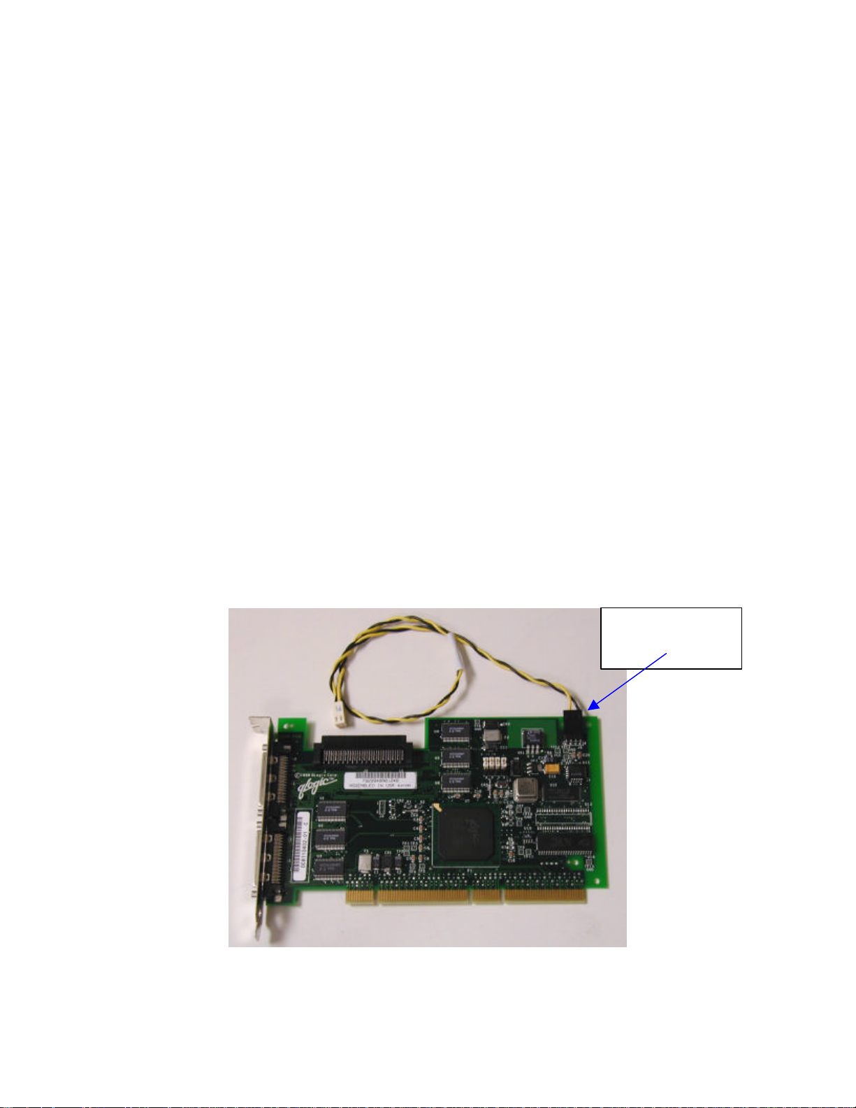
hp workstation i2000 owner’s guide
Drive activity cable
should be attached
8.4 Installing the SCSI Controller
Use the following steps to install the SCSI controller to the system.
/NOTE
The WXB PCI buses (S2 and slots 1, 2, 3, and 4) support 3.3 V cards, while the
PXB PCI bus (slots 5 and 6) support 5 V cards. Both WXB and PXB PCI buses
support universal cards. Please make certain that the PCI slot used is
compatible with the PCI card inserted in that slot.
/ NOTE
For continued EMC compliance of the system, use only those peripheral devices
having an external output connector (i.e., audio, video) which are marked as FCC
tested for home or office use (FCC Class B), and marked as Canada ICES-003
Class B compliant. For European installations, these devices are required to be
CE marked with declaration of conformity to the EMC directives (89/336/EEC).
1. Insert the Qlogic* SCSI controller into a PCI slot (slot 3 recommended, refer to
Figure 49) making sure that the controller is completely seated. Install the
retaining screw.
2. Attach the 68-pin SCSI cable connector (labeled P1) to the top connector of the
Qlogic* controller (labeled J3). Refer to Figure 54 and
3. Figure 55.
100
to J9
Figure 55. Qlogic 1280* SCSI Adapter
 Loading...