

Page 1

HPE Hyper Converged 380
Abstract
This document describes how to install and configure the HPE Hyper Converged 380 appliance and expansion nodes. This document is for
products with
Part Number: 860192-003
September 2016
Edition: 3
Installation Guide
the person who installs, administers, and troubleshoots servers and is skilled in network configuration and virtual environments. Hewlett
Packard Enterprise assumes you are qualified in the servicing of computer equipment and trained in recognizing hazards in
hazardous energy levels.
Page 2

© Copyright 2016 Hewlett Packard Enterprise Development LP
The information contained herein is subject to change without notice. The only warranties for Hewlett Packard Enterprise products and services
are set forth in the express warranty statements accompanying such products and services. Nothing herein should be construed as constituting
an additional warranty. Hewlett Packard Enterprise shall not be liable for technical or editorial errors or omissions contained herein.
Links to third-party websites take you outside the Hewlett Packard Enterprise website. Hewlett Packard Enterprise has no control over and is not
responsible for information outside the Hewlett Packard Enterprise website.
Confidential computer software. Valid license from Hewlett Packard Enterprise required for possession, use or copying. Consistent with FAR
12.211 and 12.212, Commercial Computer Software, Computer Software Documentation, and Technical Data for Commercial Items are
licensed to the U.S. Government under vendor’s standard commercial license.
Microsoft® and Windows® are either registered trademarks or trademarks of Microsoft Corporation in the United States and/or other countries.
VMware®, vCenter™, and vSphere™ are registered trademarks or trademarks of VMware, Inc. in the United States and/or other jurisdictions.
Linux® is the registered trademark of Linus Torvalds in the U.S. and other countries.
NVIDIA, the NVIDIA logo, and NVIDIA Tesla are trademarks and/or registered trademarks of NVIDIA Corporation in the U.S. and other countries.
Page 3

Contents
Introduction ............................................................................................................................................... 7
Product introduction ................................................................................................................................................. 7
Purpose of this guide ..................................................................................................................................... 7
Supported versions .................................................................................................................................................. 7
Before you begin ....................................................................................................................................... 8
Before installing ........................................................................................................................................................ 8
Networking requirements............................................................................................................................... 8
Preinstallation worksheets ...................................................................................................................... 14
Appliance networks ................................................................................................................................................ 14
Remote vCenter ..................................................................................................................................................... 15
Settings .................................................................................................................................................................. 16
iLO addresses ........................................................................................................................................................ 17
iLO IPv4 address requirements ................................................................................................................... 17
iLO address worksheet ................................................................................................................................ 17
Default user names and passwords ....................................................................................................................... 17
CloudSystem .......................................................................................................................................................... 18
Appliance components ........................................................................................................................... 20
Front panel ............................................................................................................................................................. 20
Rear panel components ......................................................................................................................................... 21
General virtualization and VDI rear panel components ............................................................................... 21
CloudSystem rear panel components ......................................................................................................... 22
Installing the HC380 appliance nodes .................................................................................................... 23
Optimum environment ............................................................................................................................................ 23
Space and airflow requirements .................................................................................................................. 23
Temperature requirements .......................................................................................................................... 24
Power requirements .................................................................................................................................... 24
Connecting a DC power cable to a DC power source ................................................................................. 24
Rack warnings ........................................................................................................................................................ 25
Installing the node into the rack .............................................................................................................................. 26
Cabling the system ................................................................................................................................................. 27
General virtualization configuration (all 1 GbE appliance)........................................................................... 28
General virtualization (10GbE appliance) and VDI configurations .............................................................. 29
CloudSystem configuration ......................................................................................................................... 30
Configuring the system ........................................................................................................................... 32
Configuring the HC380 system .............................................................................................................................. 32
Configuring the network switches ........................................................................................................................... 32
Powering on all nodes ............................................................................................................................................ 33
Configuring a laptop or workstation to access the system ..................................................................................... 33
Testing network connectivity .................................................................................................................................. 34
Licensing and installing NVIDIA Tesla M60 GPUs ................................................................................................. 34
Installing the NVIDIA GPU mode change utility on the vSphere host ......................................................... 35
Verifying the NVIDIA GPU mode ................................................................................................................. 35
Installing NVIDIA GRID Manager Software on vSphere ............................................................................. 36
Configuring the HC380 using OneView InstantOn ................................................................................................. 36
Guidelines for using OneView InstantOn .................................................................................................... 36
Completing the Introduction screen ............................................................................................................. 37
Completing the vCenter screen ................................................................................................................... 37
Completing the Health screen ..................................................................................................................... 38
Completing the IP Assignments screen....................................................................................................... 39
Completing the Credentials screen ............................................................................................................. 40
Contents 3
Page 4

Completing the Settings screen................................................................................................................... 41
Completing the Review Configuration Screen ............................................................................................. 42
Completing the Next Steps screen .............................................................................................................. 43
Installing HC380 Management UI .......................................................................................................................... 44
Completing the initial HC380 Management UI configuration .................................................................. 46
Configuring the settings .......................................................................................................................................... 46
Performing the initial HC380 Management UI setup .............................................................................................. 46
Configuring LDAP or Active Directory .................................................................................................................... 47
User roles .................................................................................................................................................... 47
Installing CloudSystem ........................................................................................................................... 48
Limitations .............................................................................................................................................................. 48
Running the installation utility ................................................................................................................................. 49
Overview...................................................................................................................................................... 49
Downloading the MySQL JDBC driver ........................................................................................................ 49
Enabling SSH on each ESXi server ............................................................................................................ 49
Running the installation utility ...................................................................................................................... 50
Datastores ................................................................................................................................................... 57
Disabling SSH on each ESXi server............................................................................................................ 59
Upgrading CloudSystem ........................................................................................................................................ 61
Prerequisites for upgrading cloud ................................................................................................................ 61
Upgrading CloudSystem 9.0 to 9.01 and 9.02............................................................................................. 61
Tenant and Provider Networking ............................................................................................................................ 61
Tenant ......................................................................................................................................................... 61
Provider ....................................................................................................................................................... 62
External ....................................................................................................................................................... 62
Validating CloudSystem ......................................................................................................................................... 63
Create router .......................................................................................................................................................... 63
Expanding the system............................................................................................................................. 64
Prerequisites to expanding the HC380 system ...................................................................................................... 64
Expanding the HC380 using OneView InstantOn .................................................................................................. 64
Expanding CloudSystem ........................................................................................................................................ 69
Compute node expansion ........................................................................................................................... 69
Pre-expansion preparation .......................................................................................................................... 69
Configure the new node in the CMC ........................................................................................................... 70
Configure the volume in vCenter ................................................................................................................. 70
Configure the VDS of vCenter ..................................................................................................................... 71
Activate the compute host cluster ................................................................................................................ 72
Troubleshooting ...................................................................................................................................... 73
Troubleshooting OneView InstantOn ..................................................................................................................... 73
Certificate error when launching vCenter web client ................................................................................... 73
HC380 nodes are not discovered ................................................................................................................ 73
OneView InstantOn hangs during deployment ............................................................................................ 73
vCenter license status on Health screen is red ........................................................................................... 74
OneView InstantOn progress indicator appears to hang ............................................................................. 74
"Invalid username and password" error appears when you specify a local vCenter ................................... 74
Application performance on management VM might decrease ................................................................... 74
"The page cannot be displayed" error message appears ............................................................................ 75
OneView InstantOn hangs with error message "0:02 Adding SAN to vCenter" .......................................... 75
vSphere HA errors .................................................................................................................................................. 75
Troubleshooting CloudSystem ............................................................................................................................... 76
Connection error to vCenter server ............................................................................................................. 76
Installation utility cannot assign the DCM network VLAN to the ESXmgmt portgroup ................................ 76
Unable to migrate host to management cluster ........................................................................................... 77
Trouble setting up storage ........................................................................................................................... 77
Distributed switches were not created as expected .................................................................................... 78
Foundation or Enterprise zip files on the datastore supplied by the factory image are not found ............... 78
Foundation or Enterprise zip files can not be unzipped .............................................................................. 79
Storage is not available for OVA images ..................................................................................................... 79
Contents 4
Page 5

Issues creating first management appliance ............................................................................................... 79
CloudSystem was not deployed successfully .............................................................................................. 80
Could not update the hpcs-data* distributed switch .................................................................................... 80
Could not register vCenter with CloudSystem ............................................................................................. 80
Could not activate compute nodes .............................................................................................................. 81
Could not create Tenant VLAN Segment Ranges ....................................................................................... 81
Could not create Tenant and Provider VLAN Networks .............................................................................. 82
Could not add Subnets to Networks ............................................................................................................ 82
Could not create router ................................................................................................................................ 82
Could not update to 9.02 ............................................................................................................................. 82
Could not update passwords ....................................................................................................................... 83
VSA volumes did not stabilize in 10 minutes…cannot continue .................................................................. 83
VM <name> did not power off - <error msg>............................................................................................... 83
Problem finding original vCenter cluster ...................................................................................................... 83
Could not find the VSA VM on host <name> ............................................................................................... 84
Deploy CloudSystem ................................................................................................................................... 84
Appendix A: Network switch configuration .............................................................................................. 85
Hewlett Packard Enterprise switches ..................................................................................................................... 85
Network cabling ........................................................................................................................................... 85
Configuring the switches ............................................................................................................................. 86
Connecting to the serial console port .......................................................................................................... 86
IRF configuration ......................................................................................................................................... 86
Cisco Nexus networking ......................................................................................................................................... 91
Network cabling ........................................................................................................................................... 91
Configuring the switches ............................................................................................................................. 92
Validating the switch configuration .............................................................................................................. 96
Uplink into existing network infrastructure ................................................................................................. 100
Configuration worksheet ....................................................................................................................................... 100
Appendix B: CloudSystem 9.0 Management Host Networking ............................................................. 102
Appendix C: CloudSystem 9.0 Compute Host Networking ................................................................... 103
Appendix D: CloudSystem 9.0 Consoles .............................................................................................. 104
Appendix E: CloudSystem Network Diagram ....................................................................................... 106
Appendix F: Remote vCenter setup ...................................................................................................... 107
Appendix G: Management group quorum consideration ...................................................................... 109
Appendix H: IP addresses for sample cluster ....................................................................................... 110
ESXi management network IP addresses worksheet .......................................................................................... 110
vSphere vMotion network IP addresses worksheet ............................................................................................. 112
Storage network IP addresses worksheet ............................................................................................................ 113
CloudSystem network IP addresses worksheet ................................................................................................... 114
Warranty and regulatory information ..................................................................................................... 116
Warranty information ............................................................................................................................................ 116
Regulatory information ......................................................................................................................................... 116
Safety and regulatory compliance ............................................................................................................. 116
Belarus Kazakhstan Russia marking ......................................................................................................... 116
Turkey RoHS material content declaration ................................................................................................ 117
Ukraine RoHS material content declaration .............................................................................................. 117
Specifications ........................................................................................................................................ 118
HC380 specifications ............................................................................................................................................ 118
Support and other resources ................................................................................................................ 119
Accessing Hewlett Packard Enterprise Support ................................................................................................... 119
Information to collect ................................................................................................................................. 119
Accessing updates ............................................................................................................................................... 119
Websites ............................................................................................................................................................... 119
Contents 5
Page 6

Remote support .................................................................................................................................................... 120
Insight Remote Support installation ........................................................................................................... 120
Acronyms and abbreviations................................................................................................................. 121
Documentation feedback ...................................................................................................................... 123
Index ..................................................................................................................................................... 124
Contents 6
Page 7

Introduction
Product introduction
The Hyper Converged 380 system is a virtualization appliance that combines compute and storage
resources in the same chassis. It is designed to be deployed easily and yet manage a variety of virtualized
workloads in medium-sized businesses and enterprises.
The system is available in three workload configurations:
• General virtualization — supports general-purpose virtualization workloads
• HPE Helion CloudSystem — open and fully integrated cloud solution delivering automation,
orchestration, and control across multiple clouds
• Virtual Desktop Infrastructure (VDI) — supports specific VDI workloads
Purpose of this guide
All hardware comes preintegrated and ready to connect to a network switch. All software, with the
exception of the VDI-specific application, comes preloaded enabling a simple installation. This guide
contains information for installing and configuring the appliance and adding expansion nodes.
Use the instructions and guidelines in this guide to perform the following tasks.
• Initial installation and deployment tasks
o Plan for the installation by using the preinstallation worksheets to collect the information required
o Install the hardware into your datacenter environment
o Connect the appliance to your network and connect to the system
o Deploy the system using the HPE OneView InstantOn configuration utility
o Install HC380 Management UI
o Complete the initial configuration of HC380 Management UI
o Install Cloud System (optional)
• Adding HC380 expansion nodes
o Expand the system
NOTE: For information about installing the VDI configuation, see HPE Reference
Architecture for VMware Horizon (with View) 6.2.2 on HPE Hyper Converged 380 on the
Hewlett Packard Enterprise website (http://www.hpe.com/info/cv).
Supported versions
The HC380 ships with a supported set of software versions that comply with the HC380 firmware and
software compatibility matrix. Over time, the HC380 matrix may be updated to support newer versions.
Customers maintain the HC380 to be in compliance with the HC380 compatibility matrix. For more
information, see the HPE Hyper Converged 380 Firmware and Software Compatibility Matrix on the
Hewlett Packard Enterprise website (http://www.hpe.com/support/hc380CMen).
Introduction 7
Page 8

Before you begin
Before installing
The HC380 installation process is designed for an IT specialist who is familiar with computer hardware
and software concepts and virtual machine networking. You are encouraged to read through this
document before you begin installation and familiarize yourself with each of the steps.
You need the following items to successfully complete the installation:
• Network switches and cables that meet the following requirements:
o 1Gb connections for each the iLO and 1Gb LOM ports on each node
o 1Gb or 10Gb connections the FlexLOM ports on each node
o 1Gb and 10Gb connections IPv6 capable and enabled
• Appropriate power and rack space for the HC380 nodes and any other hardware that may be part of
the environment
• Laptop or other computer that can be network cabled directly to a node to begin configuration. The
instructions assume that you are using a Windows-based computer with Remote Desktop Services
installed.
• VMware vSphere Enterprise or Enterprise Plus license
Networking requirements
Planning and executing the network installation is the single most important item to a successful
installation. Whether you are integrating into an existing data center infrastructure or isolating the
appliance from other resources, you must consider not only the initial appliance installation, but also plan
for any future expansion.
IMPORTANT: The networking choices made during the initial installation may not be
reversible at a later time without a complete reinstallation.
Flat or VLAN-tagged networks
The HC380 appliance creates and utilizes different internal networks to segregate traffic, including ESXi
management, vMotion, and storage. These networks may be configured in either a "flat" or VLAN-tagged
network topology, depending on the workload configuration and your specific network requirements. Here
are the options based on workload type:
• General virtualization: Flat or VLAN-tagged network
• CloudSystem: VLAN-tagged network only
• VDI: Flat or VLAN-tagged network
If you have a choice and are unsure about which network type to use, consult your network administrator.
IPv6 enablement at switch level
The HC380 requires that the 1Gb and 10Gb switches be IPv6 enabled.
Most switches have IPv6 enabled by default, but some companies may explicitly disable IPv6 Link Local
by setting up access control lists (ACLs) or performing other IT functions.
Before you begin 8
Page 9

If IPv6 is not enabled, the HC380 nodes will not be discovered during the installation progress and the
Addresses
HC380
172.28.0.1
1
This value is provided during the
HC380 OneView
172.28.0.2
1
This value is provided during the
installation and deployment will not complete.
IP address assignments
Note the following points about the IP address assignments:
• The appliance uses a private IPv4 network (192.168.42.0/24) for internal system communications
that can not be used by other devices sharing the same network.
• If you plan to expand the number of nodes in the future, Hewlett Packard Enterprise recommends
that you preallocate and leave enough room in the IP address ranges. Preallocating allows you to
add future nodes with IP addresses matching the initial installation subnet ranges. If you choose not
to preallocate the IP addresses now, the future nodes require IP addresses within the subnet ranges
used during initial system deployment.
• You need between 5 and 119 IPv4 addresses, depending upon whether you are performing an initial
configuration or expanding the HC380 cluster.
o If you are performing an initial configuration, the system requires between 15 and 119 IPv4
addresses, depending on the number of nodes in your initial configuration and whether you are
installing CloudSystem.
o If you are expanding an existing HC380 cluster, you need between 5 and 70 IPv4 addresses,
depending on the number of nodes you are adding and whether you are using CloudSystem.
• Since the OneView InstantOn configuration utility accepts a starting IP address and automatically
increments the IP addresses by the number of nodes in the initial configuration or expansion, some
of the IP addresses must be contiguous.
• For examples and worksheets to help you plan your networks, see "Appendix H: IP addresses for
sample cluster (on page 110)."
Planning your appliance networks
Use the topics in this section to plan your appliance networks and determine the IP addresses that are
required for your installation.
ESXi management network IP addresses
The ESXi management network assigned in OneView InstantOn requires contiguous IP addresses. When
assigning IP addresses for the ESXi management network, the Management VM IP address is assigned
first and is the starting IP address. Record the starting IP address on the preinstallation worksheet
("Preinstallation worksheets" on page 14).
You must choose separately the HC380 Management UI and HC380 OneView VM IP addresses on the
ESXi management network so that they do not conflict with the IP addresses assigned by OneView
InstantOn.
When planning the ESXi management network, Hewlett Packard Enterprise recommends that you use
the convention shown in the table.
Network
Purpose Example Count Notes
W.X.Y.n
W.X.Y.n+1
Management UI VM
VM
HC380 Management UI
installation.
initial configuration of the HC380
Management UI
Before you begin 9
Page 10

Addresses
HC380
172.28.0.3
1
This value is the starting IP
ESXi Nodes (16
172.28.0.4 –
1 - 16
These address values are
CloudSystem
(optional)
172.28.0.20 -
25
For CloudSystem only.
CloudSystem
172.28.0.45 –
3
For CloudSystem only.
172.28.0.1
1
HC380 OneView VM
172.28.0.2
1
HC380 Management VM
172.28.0.3*
1
172.28.0.4* -
172.28.0.19*
16
Total: 19
VMs (optional)
172.28.0.20 -
25
172.28.0.45 –
172.28.0.47
3
Total: 47
Network
W.X.Y.n+2
W.X.Y.n+3 W.X.Y.n+18
W.X.Y.n+19 –
W.X.Y.n+43
W.X.Y.n+44 –
W.X.Y.n+46
Purpose Example Count Notes
Management VM
nodes)
Management &
Compute VMs
Console VIP
(optional)
172.28.0.19
172.28.0.44
172.28.0.47
address on the IP assignments
screen of OneView InstantOn.
automatically and sequentially
assigned to the nodes by
OneView InstantOn, starting
immediately after the HC380
Management VM IP address.
The examples shown above show that all IP addresses are contiguous. However, the only addresses that
the system requires to be contiguous are the addresses used by HC380 management VM and the ESXi
management network nodes. The other addresses are not required to be contiguous, but Hewlett Packard
Enterprise recommends that they be in the same address range, to enable expansion at a later date.
Use one of the following calculations to help you determine the number of IPv4 addresses you need for
your ESXi management network, where N is the number of nodes in your cluster.
• N + 3 (for General virtualization and VDI)
• N + 31 (for CloudSystem)
Use the following guidelines and examples for a 16-node and two-node cluster.
16-node cluster
For a 16-node cluster, you need between 19 and 47 IP addresses.
Purpose Example Count
HC380 Management UI VM
ESXi Nodes (16 nodes)
CloudSystem Management & Compute
CloudSystem Console VIP (optional)
* Must be contiguous
Two-node cluster
172.28.0.44
For a two-node cluster, Hewlett Packard Enterprise recommends that you reserve IP addresses to allow
for future expansion. Therefore, you need between 19 and 47 IP addresses.
Before you begin 10
Page 11

172.28.0.1
1
HC380 OneView VM
172.28.0.2
1
172.28.0.3*
1
172.28.0.4*
172.28.0.5*
2
172.28.0.6* -
14
Total: 19
VMs (optional)
172.28.0.20-
25
172.28.0.45 –
3
Total: 47
Purpose Example Count
HC380 Management UI VM
HC380 Management VM
ESXi nodes (two nodes)
Reserved for expansion
172.28.0.19*
CloudSystem Management & Compute
CloudSystem Console VIP (optional)
* Must be contiguous
172.28.0.44
172.28.0.47
vSphere vMotion network IP addresses
The vSphere vMotion network requires contiguous IPv4 addresses, one for each HC380 node in the
cluster. In OneView InstantOn, you provide the first IP address as the starting address, and the program
automatically assigns all other IP addresses in sequence. Record the starting IP address on the
preinstallation worksheet ("Preinstallation worksheets" on page 14).
If you are installing CloudSystem, no additional IP addresses are needed.
Use the following examples for the required number of IP addresses:
• For a 16-node cluster, you will need 16 contiguous IPv4 addresses.
• For a two-node cluster, you will need 2 contiguous IPv4 addresses.
• For a three-node cluster, you will need 3 contiguous IPv4 addresses.
Storage network IP addresses
The storage network requires five contiguous IPv4 addresses for the first node and three contiguous IPv4
addresses for every additional node. These IP addresses are used by the HC380 Management VM, iSCSI
initiators, and HPE StoreVirtual.
Use the following examples for the required number of IP addresses:
• For a sixteen-node cluster, you will need 50 contiguous IPv4 addresses
• For a two-node cluster, you will need 8 contiguous IPv4 addresses
• For a three-node cluster, you will need 11 contiguous IPv4 addresses
In OneView InstantOn, you provide the first IP address as the starting address, and the program
automatically assigns all other IP addresses in sequence. Record the starting IP address on the
preinstallation worksheet ("Preinstallation worksheets" on page 14).
Planning for expansion
If you are planning to expand in the future, Hewlett Packard Enterprise recommends that you preallocate
the IP addresses that are needed for the future nodes. For each new expansion node, you need five IPv4
Before you begin 11
Page 12

addresses for OneView InstantOn. HC380 Management UI also requires the iLO IPv4 address for the
node.
The five IPv4 addresses are used as follows:
• One address is used for the ESXi host.
• One address is used for the vSphere vMotion component on the ESXi host.
• Three addresses are used by the storage network, including two for the iSCSI initiators.
The following IP addresses from the initial system deployment are reused for the expansion process:
• HC380 Management UI VM
• HC380 OneView VM
• HC380 Management VM
• StoreVirtual cluster
If you are planning to expand to a 16-node system in the future, Hewlett Packard Enterprise recommends,
but does not require, that you preallocate the IP addresses that will be needed for the remaining nodes
now. Preallocating IP addresses for all 16 nodes allows you to assign contiguous blocks of IP addresses
to the various networks.
For each network type (ESXi, vSphere vMotion, Storage), you choose the first IP address in that group’s
range. After that IP address is chosen, OneView InstantOn will automatically increment and assign the
remaining IP addresses for that group.
VMware vCenter
The HC380 can be deployed with either a local vCenter Server instance, or with a remote vCenter Server
(or vCenter Server appliance) instance. Regardless of the vCenter Server location, it must have HPE
OneView for vCenter integrated. During OneView InstantOn configuration, OneView InstantOn checks
that the specified vCenter Server has OneView for vCenter configured, and will not continue until this
check is complete. For additional information, see "Appendix F: Remote vCenter setup (on page 107)."
NOTE: A remote vCenter setup is not supported with CloudSystem.
Before deploying the HC380 with the remote vCenter option, ensure that the following requirements are
met on the remote server on which VMware vCenter Server and OneView for VMware vCenter are
installed:
• Verify that the remote server is configured on a network that is accessible to the 10 GbE switches
that are connected to the HC380 system. You need the IP address for the remote vCenter server and
the default port used for SSO.
• Verify that the remote vCenter is not running on a host intended to be an HC380 appliance instance.
• Disable the firewalls for the HC380 appliance, or enable the following ports for inbound access:
o HPE HTTPS Port 3501 TCP
o HPE UIM Port 3504 TCP (must be accessible from the Management VM of the system running
OneView InstantOn)
NOTE:
• For more information about these ports, see “Default port values” in HP OneView for
• These firewall or port settings are only required during deployment of a new system
VMware vCenter Installation Guide found on the Hewlett Packard Enterprise website
(http://www.hpe.com/info/ovvcenter/docs).
installation or a system expansion. Once that deployment is complete, you can either
re-enable the firewalls or disable port access.
Before you begin 12
Page 13

• Install VMware vCenter Server. Hewlett Packard Enterprise recommends that you always install the
• Install OneView for VMware vCenter and ensure that it has access to the networks that will be used
• Ensure that you have access to the OneView for VMware vCenter administrator credentials on the
• Verify that the remote server can support the additional system hosts, datacenter, and Virtual
HPE iLO 4
Although iLO 4 is not required for daily use, Hewlett Packard Enterprise recommends that you configure
the iLO of each HC380 server as part of the initial setup. iLO is required when performing a node
recovery, for perform a firmware update, and for CloudSystem. The default iLO credentials can be found
on the toe tag on each HC380 node.
For more information about configuring iLO, see HPE iLO 4 User Guide, which is available on the Hewlett
Packard Enterprise website (http://www.hpe.com/info/ilo/docs).
latest updates of the software.
for HC380 ESXi management and for HC380 storage.
remote server. These credentials are used by OneView InstantOn during deployment.
Machines that will be installed or added (expanded).
NOTE: To determine the supported limits for each version, see the VMware vCenter Server
documentation.
Before you begin 13
Page 14

Preinstallation worksheets
added during an expansion)
Subnet Mask
Gateway
Subnet Mask
VLAN ID (optional, for CloudSystem)
Subnet Mask
Gateway
VLAN ID (optional, for CloudSystem)
This section contains information lists for data needed during the appliance installation and configuration.
If you are expanding an existing configuration, you will need to obtain data from the existing appliance and
Appliance networks
add any data for an expansion node.
For each network type (ESXi, vSphere vMotion, Storage), you choose the first IP address in the range for
that group. Once that IP address is chosen, OneView InstantOn automatically increments and assigns the
remaining IP addresses for that group. Each network type assigned in OneView InstantOn requires
contiguous IP addresses.
Use the worksheets for an initial installation and for an expansion.
ESXi Network Components
To help you plan the ESXi management network, see "ESXi management network IP addresses (on page
9)."
ESXi network components Value
Starting IP address
(used by the HC380 Management VM during
initial installation or by the first ESXi node being
vSphere vMotion IPs
To help you plan the vSphere vMotion network, see "vSphere vMotion network IP addresses (on page
11)."
vSphere vMotion IPs Value
Starting IP address
Storage network IPs
To help you plan the storage network, see "Storage network IP addresses (on page 11)."
Storage network IPs Value
Starting IP address
HC380 Management UI VM
Preinstallation worksheets 14
Page 15

For the HC380 Management UI initial configuration, you assign two additional IPv4 addresses for the
Item
Value
password
HC380 Management UI VM IP address
Subnet Mask
Gateway
HPE OneView VM IP address
Subnet Mask
Port on remote vCenter system
User name for vCenter on remote system
Password for vCenter on remote system
on IP assignment screen)
on IP assignment screen)
IP assignment screen)
HC380 Management UI and HPE OneView components, listed in the worksheet.
To help you determine the IP addresses to use in this worksheet, see "ESXi management network IP
addresses (on page 9)."
HC380 Management UI VM administrator
Gateway
Remote vCenter
Use this section only:
• if you plan to use a remote vCenter in your initial HC380 installation
• if you are expanding and you selected the remote vCenter option during the initial installation
Initial installation
If you choose the remote vCenter option on the OneView InstantOn vCenter screen, you are required to
enter an HC380 Management VM IP address, subnet mask, gateway and DNS addresses into the
Management VM ESX Connectivity area on that screen. These values are used to configure the
Management VM so that HP OneView InstantOn can verify that the remote server can be accessed and
that the remote instance of HPE OneView for VMware vCenter is installed at the correct, minimum
version.
The HC380 Management VM IP address, subnet mask and gateway are automatically populated on the
OneView InstantOn IP assignment screen as the starting address for the ESXi Network Component. The
DNS value is used on the OneView InstantOn Settings screen.
For more information on a remote vCenter setup, see "Appendix F: Remote vCenter setup (on page
107)."
Item Value
IP address of remote vCenter system
IP address for HC380 Management VM on the ESXi
management network
(same as starting address of the ESXi components
Subnet Mask for the HC380 ESXi management
network
(same as subnet mask value of the ESXi components
Gateway on the HC380 ESXi management network
(same as gateway value of the ESXi components on
Preinstallation worksheets 15
Page 16

Item Value
(same as DNS value from Settings screen)
Automatically populated from initial installation
Port
Automatically populated from initial installation
User name
Automatically populated from initial installation
Password
and can include numbers, or the _* characters
\ / , . ; ' " : characters
Only needed if connecting to a local vCenter
Storage network DNS
Storage network NTP (optional)
Storage network mail server
Storage network mail server port
Sender email
NFS file share path (for 2-node system)*
Use same value provided during initial installation
Use same value provided during initial installation
DNS Server on the HC380 ESXi management
network
Expansion
During an expansion, you are required to provide the password for the remote vCenter user name.
Remote vCenter server item Value
IP address
Settings
Use the following checklist to set up your storage network for a new installation.
Item Value
StoreVirtual user name
Must contain 3–30 characters, begin with a letter,
StoreVirtual password
Must contain 5–40 characters and not include the
vSphere license (optional)
Recipient email
* For more information, see "Appendix G: Management group quorum consideration (on page 109)."
Use the following checklist for an expansion.
Item Value
StoreVirtual user name
StoreVirtual password
Preinstallation worksheets 16
Page 17

iLO addresses
iLO IPv4 address requirements
Each HC380 server has an iLO which is manually configured with an IPv4 address on the ESX
management network. HC380 Management UI imports the iLO for each of the servers by IP address
during its configuration process, so that it can then manage the iLOs.
HC380 Management UI does not require that you enter the serial number, but it does associate each IP
address to a serial number. All of the iLO IP addresses must be accessible from the ESXi management
network.
For more information about iLO, see "HPE iLO 4 (on page 13)."
iLO address worksheet
Use the worksheet to record the node serial number and the iLO IP address associated to that serial
number.
During an expansion, you can use this same worksheet and then manually enter the IPv4 addresses into
HC380 Management UI (Settings area) for each new node that you are adding.
Node Serial number iLO IP address
1
2
3
4
5
6
7
8
9
10
11
12
13
14
15
16
Default user names and passwords
The following default usernames and passwords are shipped with the appliance or are needed to
complete the setup.
Preinstallation worksheets 17
Page 18

HyperConv!234
HC380 Management VM
administrator
HyperConv!234
root
HyperConv!234
Console
admin
unset
OpenStack Horizon Console
admin
unset
Appliances
cloudadmin
cloudadmin
CSA MarketPlace Portal
consumer
cloud
Operations Orchestration
administrator
unset
DCM IP Range: (25 contiguous IPs)
DCM VLAN ID:
DCM CIDR:
DCM Gateway:
DCM Management Appliance VIP:
DCM Management Appliance FQDN:
DCM Cloud Controller VIP:
DCM Cloud Controller FQDN:
DCM Enterprise Appliance VIP:
DCM Enterprise Appliance FQDN:
Cloud Management Network
CLM VLAN ID:
Consumer Access Network
CAN IP Range: (+3 contiguous IPs)
CAN VLAN ID:
CAN CIDR:
CAN Gateway:
CAN Cloud Controller VIP:
CAN Cloud Controller FQDN:
CAN Enterprise Appliance VIP:
CAN Enterprise Appliance FQDN:
Item Username Password
vCenter Server (local)
ESXi shell
iLO administrator
CloudSystem Operations
CloudSystem Management
For more information about iLO, see "HPE iLO 4 (on page 13)."
CloudSystem
Use the following worksheet to assist in the pre-planning for the CloudSystem workload configuration. If
you are installing the general virtualization or VDI workload configurations, you can skip this spreadsheet.
While the Block and Object networks are not used, the installation process requires a VLAN for each
network. Assign two unused VLAN IDs for these networks that do not interfere with any of your other
networks.
For more information, see "Appendix E: CloudSystem Network Diagram (on page 106)."
Item Value
Data Center Management Network
Preinstallation worksheets 18
Page 19

Item Value
External Network
External VLAN ID:
Provider Networks
Provider 1 VLAN ID:
Provider 1 CIDR:
Provider 2 VLAN ID:
Provider 2 CIDR:
Provider 3 VLAN ID:
Provider 3 CIDR:
Provider 4 VLAN ID:
Provider 4 CIDR:
Tenant Networks
Tenant 1 VLAN ID:
Tenant 1 CIDR:
Tenant 2 VLAN ID:
Tenant 2 CIDR:
Tenant 3 VLAN ID:
Tenant 3 CIDR:
Tenant 4 VLAN ID:
Tenant 4 CIDR:
Block Storage Networks
Block Storage VLAN ID:
Object Proxy Network
Object Proxy VLAN ID:
Preinstallation worksheets 19
Page 20
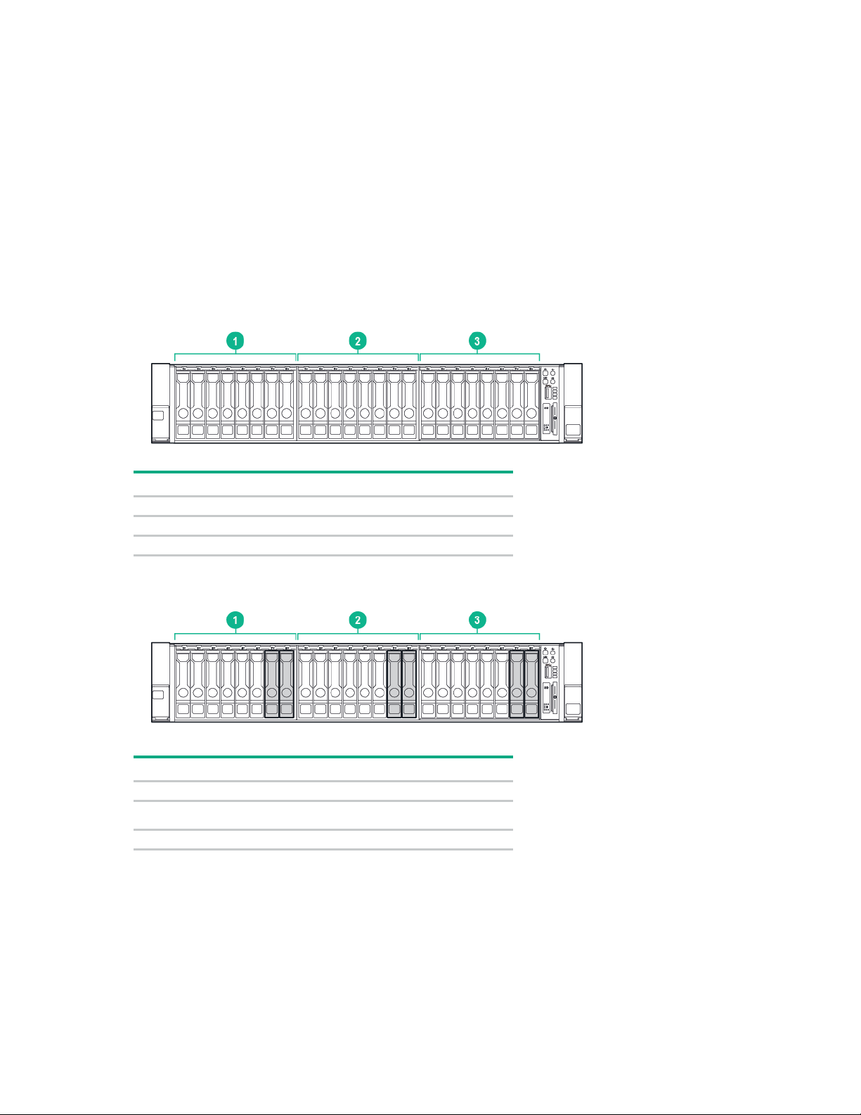
Appliance components
1
Bay 3, with 8 HDDs or SSDs (optional)
2
Bay 2, with 8 HDDs or SSDs (optional)
3
Bay 1, with 8 HDDs or SSDs
Item
Description
1
Bay 3, with 6 HDDs and 2 SSDs (optional)
Bay 2, with 6 HDDs and 2 SSDs (optional)
3
Bay 1, with 6 HDDs and 2 SSDs
The following diagrams are examples to help you understand important component locations. Because
the HC380 is available with an array of options, storage, networking and power components will vary
Front panel
depending on your specific configuration.
• Front panel with HDDs or SSDs in all three storage bays
Item Description
• Front panel hybrid configuration with 6 HDDs and 2 SSDs in each storage bay
2
Appliance components 20
Page 21
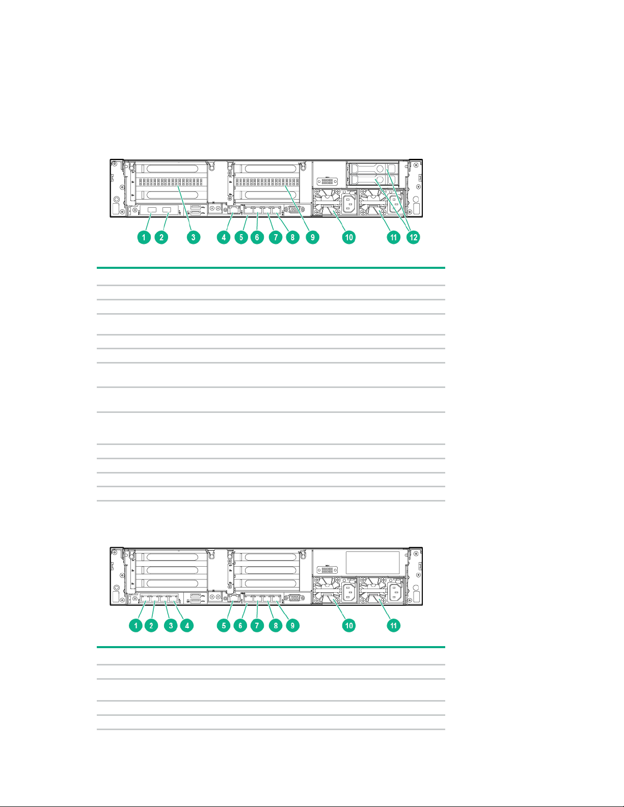
Rear panel components
Item
Description
1
10 GbE NIC Port 2
2
10 GbE NIC Port 1 (FlexLOM)
nVIDIA graphics card (VDI only, optional)
4
iLO connector
5
1 GbE RJ-45 port 1 (do not use during initial configuration)
1 GbE RJ-45 port 2 (for connection to a laptop or workstation for setup, on
1 GbE RJ-45 port 3 (not used during initial configuration; available for
1 GbE RJ-45 port 4 (not used during initial configuration; available for
9
nVIDIA graphics card (VDI only, optional)
10
Power supply 1 (PS1)
11
Power supply 2 (PS2)
12
Rear panel HDDs (VDI only, optional)
1
1 GbE RJ-45 port 8
1 GbE RJ-45 port 7
3
1 GbE RJ-45 port 6
4
1 GbE RJ-45 port 5
General virtualization and VDI rear panel components
• 10 GbE appliance
3
6
management VM)
7
customer network)
8
customer network)
• All 1 GbE appliance (General virtualization only)
Item Description
2
Appliance components 21
Page 22

5
iLO connector
6
1 GbE RJ-45 port 1 (Do not use during initial configuration)
7
1 GbE RJ-45 port 2 (For connection to a laptop or workstation for setup, on
1 GbE RJ-45 port 3 (not used during initial configuration; available for
1 GbE RJ-45 port 4 (not used during initial configuration; available for
10
Power supply 1 (PS1)
11
Power supply 2 (PS2)
Item
Description
1
10 GbE NIC Port 2
2
10 GbE NIC Port 1
3
10 GbE NIC (Ports 4 and 3)
4
10 GbE NIC (Ports 6 and 5)
5
iLO connector
6
1 GbE RJ-45 port 1 (do not use during initial configuration)
1 GbE RJ-45 port 2 (for connection to a laptop or workstation for setup, on
1 GbE RJ-45 port 3 (not used during initial configuration; available for
1 GbE RJ-45 port 4 (not used during initial configuration; available for
Power supply 2 (PS1)
Power supply 2 (PS2)
management VM)
8
customer network)
9
customer network)
CloudSystem rear panel components
7
8
9
10
management VM)
customer network)
customer network)
11
Appliance components 22
Page 23

Installing the HC380 appliance nodes
arrangement ensures proper airflow. Using a rack without blanking panels results in improper
If the 42U rack includes closing front and rear doors, you must allow
The clearance between the installed rack component and the side panels of the rack
This section provides instructions for installing the appliance nodes into a rack and cabling the network.
Optimum environment
When installing the server in a rack, select a location that meets the environmental standards described in
Space and airflow requirements
this section.
To allow for servicing and adequate airflow, observe the following space and airflow requirements when
deciding where to install a rack:
• Leave a minimum clearance of 63.5 cm (25 in) in front of the rack.
• Leave a minimum clearance of 76.2 cm (30 in) behind the rack.
• Leave a minimum clearance of 121.9 cm (48 in) from the back of the rack to the back of another rack
or row of racks.
Hewlett Packard Enterprise nodes draw in cool air through the front door and expel warm air through the
rear door. Therefore, the front and rear rack doors must be adequately ventilated to allow ambient room
air to enter the cabinet, and the rear door must be adequately ventilated to allow the warm air to escape
from the cabinet.
CAUTION: To prevent improper cooling and damage to the equipment, do not block the
ventilation openings.
When vertical space in the rack is not filled by a server or rack component, the gaps between the
components cause changes in airflow through the rack and across the servers. Cover all gaps with
blanking panels to maintain proper airflow.
CAUTION: Always use blanking panels to fill empty vertical spaces in the rack. This
cooling that can lead to thermal damage.
The 9000 and 10000 Series Racks provide proper server cooling from flow-through perforations in the
front and rear doors that provide 64 percent open area for ventilation.
CAUTION: When using a Compaq branded 7000 series rack, install the high airflow rack
door insert (PN 327281-B21 for 42U rack, PN 157847-B21 for 22U rack) to provide proper
front-to-back airflow and cooling.
CAUTION: If a third-party rack is used, observe the following additional requirements to
ensure adequate airflow and to prevent damage to the equipment:
• Front and rear doors—
5,350 sq cm (830 sq in) of holes evenly distributed from top to bottom to permit adequate
airflow (equivalent to the required 64 percent open area for ventilation).
• Side—
must be a minimum of 7 cm (2.75 in).
Installing the HC380 appliance nodes 23
Page 24

Temperature requirements
es and voltage spikes and keeps the system in operation during a power
NEC and
To ensure continued safe and reliable equipment operation, install or position the system in a
well-ventilated, climate-controlled environment.
The maximum recommended ambient operating temperature (TMRA) for most server products is 35°C
(95°F). The temperature in the room where the rack is located must not exceed 35°C (95°F).
CAUTION: To reduce the risk of damage to the equipment when installing third-party options:
• Do not permit optional equipment to impede airflow around the server or to increase the
internal rack temperature beyond the maximum allowable limits.
• Do not exceed the manufacturer’s TMRA.
Power requirements
Installation of this equipment must comply with local and regional electrical regulations governing the
installation of information technology equipment by licensed electricians. This equipment is designed to
operate in installations covered by NFPA 70, 1999 Edition (National Electric Code) and NFPA-75, 1992
(code for Protection of Electronic Computer/Data Processing Equipment). For electrical power ratings on
options, refer to the product rating label or the user documentation supplied with that option.
WARNING: To reduce the risk of personal injury, fire, or damage to the equipment, do not
overload the AC supply branch circuit that provides power to the rack. Consult the electrical
When installing more than one server, you may need to use additional power distribution devices to safely
provide power to all devices. Observe the following guidelines:
authority having jurisdiction over wiring and installation requirements of your facility.
CAUTION: Protect the server from power fluctuations and temporary interruptions with a
regulating uninterruptible power supply. This device protects the hardware from damage
caused by power surg
failure.
• Balance the server power load between available AC supply branch circuits.
• Do not allow the overall system AC current load to exceed 80% of the branch circuit AC current
rating.
• Do not use common power outlet strips for this equipment.
Connecting a DC power cable to a DC power source
• Provide a separate electrical circuit for the server.
WARNING: To reduce the risk of electric shock or energy hazards:
• This equipment must be installed by trained service personnel, as defined by the
IEC 60950-1, Second Edition, the standard for Safety of Information Technology
Equipment.
• Connect the equipment to a reliably grounded Secondary circuit source. A Secondary
circuit has no direct connection to a Primary circuit and derives its power from a
transformer, converter, or equivalent isolation device.
• The branch circuit overcurrent protection must be rated 27 A.
WARNING: When installing a DC power supply, the ground wire must be connected before
the positive or negative leads.
Installing the HC380 appliance nodes 24
Page 25

WARNING:
Remove power from the power supply before performing any installation steps or
If the DC connection exists between the earthed conductor of the DC supply circuit
This equipment should be located in the same immediate area (such as adjacent cabinets)
uipment that has a connection between the earthed conductor of the same
Switching or disconnecting devices should not be in the earthed circuit conductor between
The minimum nominal thread diameter of a pillar or stud type terminal must be
At least two people are needed to safely unload the rack from the pallet. An empty 42U rack
maintenance on the power supply.
CAUTION: The server equipment connects the earthed conductor of the DC supply circuit to
the earthing conductor at the equipment. For more information, see the documentation that
ships with the power supply.
CAUTION:
and the earthing conductor at the server equipment, the following conditions must be met:
• This equipment must be connected directly to the DC supply system earthing electrode
conductor or to a bonding jumper from an earthing terminal bar or bus to which the DC
supply system earthing electrode conductor is connected.
•
as any other eq
DC supply circuit and the earthing conductor, and also the point of earthing of the DC
system. The DC system should be earthed elsewhere.
• The DC supply source is to be located within the same premises as the equipment.
•
the DC source and the point of connection of the earthing electrode conductor.
To connect a DC power cable to a DC power source:
1. Cut the DC power cord ends no shorter than 150 cm (59.06 in).
2. If the power source requires ring tongues, use a crimping tool to install the ring tongues on the power
cord wires.
IMPORTANT: The ring terminals must be UL approved and accommodate 12 gauge wires.
IMPORTANT:
3.5 mm (0.138 in); the diameter of a screw type terminal must be 4.0 mm (0.157 in).
3. Stack each same-colored pair of wires and then attach them to the same power source. The power
cord consists of three wires (black, red, and green).
For more information, see the documentation that ships with the power supply.
Rack warnings
WARNING: To reduce the risk of personal injury or damage to the equipment, be sure that:
• The leveling jacks are extended to the floor.
• The full weight of the rack rests on the leveling jacks.
• The stabilizing feet are attached to the rack if it is a single-rack installation.
• The racks are coupled together in multiple-rack installations.
• Only one component is extended at a time. A rack may become unstable if more than one
component is extended for any reason.
WARNING: To reduce the risk of personal injury or equipment damage when unloading a
rack:
•
can weigh as much as 115 kg (253 lb), can stand more than 2.1 m (7 ft) tall, and might
become unstable when being moved on its casters.
• Never stand in front of the rack when it is rolling down the ramp from the pallet. Always
handle the rack from both sides.
Installing the HC380 appliance nodes 25
Page 26
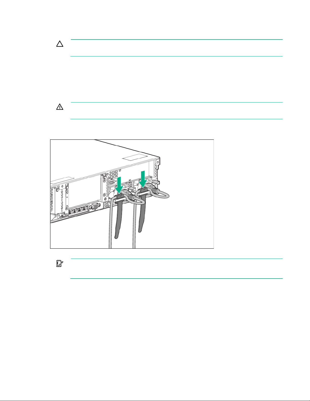
Always plan the rack installation so that the heaviest item is on the bottom of the
To reduce the risk of electric shock, fire, or damage to the equipment, do not plug
slack in each of the cables to prevent damage to the cables when the server is extended from
Installing the node into the rack
CAUTION:
rack. Install the heaviest item first, and continue to populate the rack from the bottom to the top.
1. Install the server and cable management arm into the rack. For more information, see the installation
instructions that ship with the 2U Quick Deploy Rail System.
2. Connect peripheral devices to the server. For information on identifying connectors, see one of the
following:
o "General virtualization and VDI rear panel components (on page 21)"
o "CloudSystem rear panel components (on page 22)"
WARNING:
telephone or telecommunications connectors into RJ-45 connectors.
3. Connect the power cord to the rear of the server.
4. Install the power cord anchors.
5. Secure the cables to the cable management arm.
IMPORTANT: When using cable management arm components, be sure to leave enough
the rack.
Installing the HC380 appliance nodes 26
Page 27

ems placed against
it. Pay particular attention to the plug, electrical outlet, and the point where the cord extends
6. Connect the power cord to the AC power source.
WARNING: To reduce the risk of electric shock or damage to the equipment:
• Do not disable the power cord grounding plug. The grounding plug is an important safety
feature.
• Plug the power cord into a grounded (earthed) electrical outlet that is easily accessible at all
times.
• Unplug the power cord from the power supply to disconnect power to the equipment.
• Do not route the power cord where it can be walked on or pinched by it
from the node.
Cabling the system
This section provides some cabling examples to help you properly cable your appliance. Your
configuration may differ from the examples, but the details should provide guidance for you to properly
cable the appliance in your environment.
After completing the network connections, be sure to connect the power cables to the system.
Hewlett Packard Enterprise recommends two 10GbE or 1GbE (if 1GbE solution is used) switches
configured in a highly available configuration to ensure a network switch failure does not prevent access
to the HC380 configuration. Examples on how to configure both HPE 5900 series switches and Cisco
Nexus 5600 switches are provided in "Appendix A: Network switch configuration (on page 85)."
Installing the HC380 appliance nodes 27
Page 28
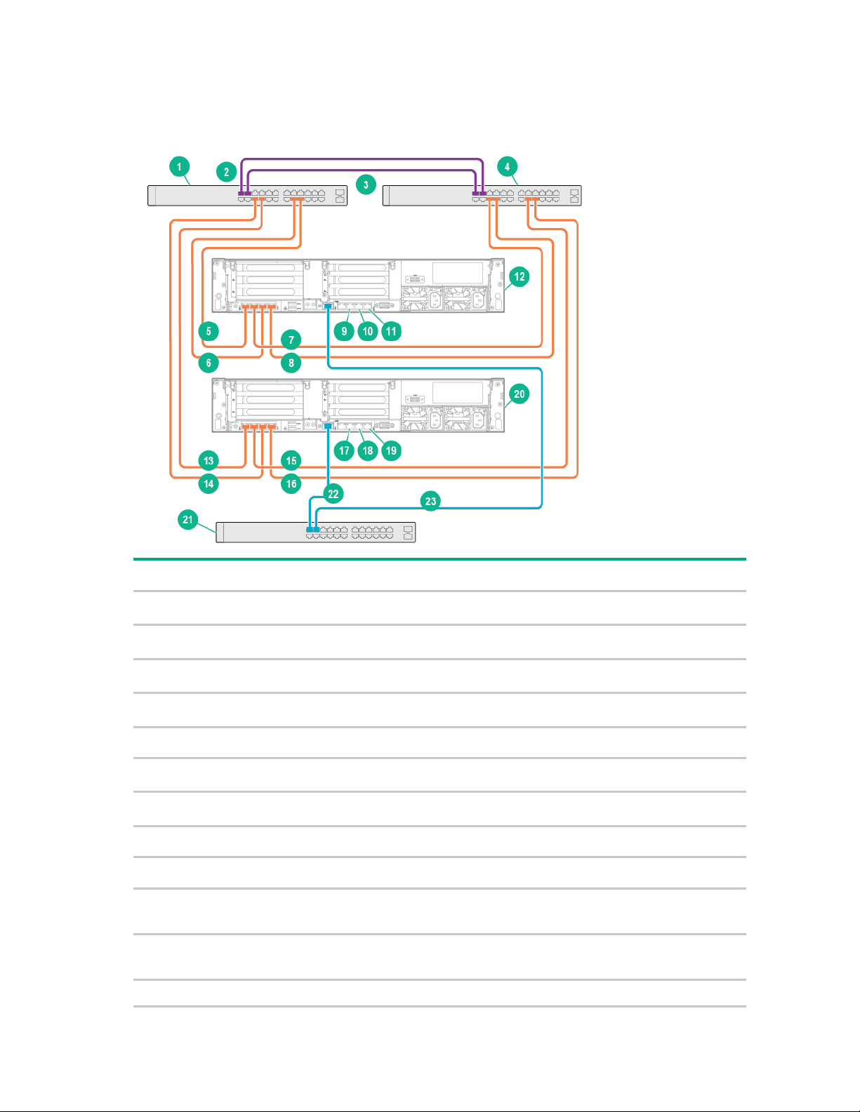
General virtualization configuration (all 1 GbE appliance)
1 GbE Switch A (IPv6 enabled)
13
Connect Node 2, Port 4 to Switch A (IPv6
Interconnect switch links
14
Connect Node 2, Port 2 to Switch A (IPv6
Interconnect switch links
15
Connect Node 2, Port 3 to Switch B (IPv6
1 GbE Switch B (IPv6 enabled)
16
Connect Node 2, Port 1 to Switch B (IPv6
Connect Node 1, Port 4 to Switch A (IPv6
enabled)
17
1GbE RJ-45 port 2 (not used)
Connect Node 1, Port 2 to Switch A (IPv6
18
1GbE RJ-45 port 3 (not used during initial
Connect Node 1, Port 3 to Switch B (IPv6
19
1GbE RJ-45 port 4 (not used during initial
Connect Node 1, Port 1 to Switch B (IPv6
enabled)
20
Node 2
1GbE RJ-45 port 2 (for connection to a
laptop or workstation for setup)
21
1 GbE Switch
1GbE RJ-45 port 3 (not used during initial
network)
22
Connect Node 2, iLO port to 1 GbE Switch
1GbE RJ-45 port 4 (not used during initial
network)
23
Connect Node 1, iLO port to 1 GbE Switch
Node 1
The following cabling example shows the use of three 1 GbE switches with the all 1 GbE appliance. This
example applies to the General Virtualization workload configuration only.
Item Description Item Description
1
2
3
4
5
6
enabled)
7
enabled)
8
9
10
configuration; available for customer
11
configuration; available for customer
enabled)
enabled)
enabled)
enabled)
configuration; available for customer network)
configuration; available for customer network)
12
Installing the HC380 appliance nodes 28
Page 29

10 GbE Switch A (IPv6 enabled)
11
Connect Node 2, Port 2 to Switch A (IPv6
Interconnect switch links
12
Connect Node 2, Port 1 to Switch B (IPv6
3
Interconnect switch links
13
1GbE RJ-45 port 2 (not used)
10 GbE Switch B (IPv6 enabled)
14
1GbE RJ-45 port 3 (not used during initial
Connect Node 1, Port 2 to Switch A (IPv6
15
1GbE RJ-45 port 4 (not used during initial
Connect Node 1, Port 1 to Switch B (IPv6
enabled)
16
Node 2
1GbE RJ-45 port 2 (for connection to a
laptop or workstation for setup)
17
1 GbE Switch
1GbE RJ-45 port 3 (not used during initial
network)
18
Connect Node 2, iLO port to 1 GbE Switch
1GbE RJ-45 port 4 (not used during initial
network)
19
Connect Node 1, iLO port to 1 GbE Switch
Node 1
General virtualization (10GbE appliance) and VDI configurations
The following cabling example shows the use of two 10 GbE switches and one 1 GbE switch. This
example applies to both the General Virtualization and VDI workload configurations. Though the rear
components might vary for each configuration, the cabling for the two configurations is similar.
Item Description Item Description
1
2
4
5
enabled)
6
7
8
configuration; available for customer
9
configuration; available for customer
10
enabled)
enabled)
configuration; available for customer network)
configuration; available for customer network)
Installing the HC380 appliance nodes 29
Page 30
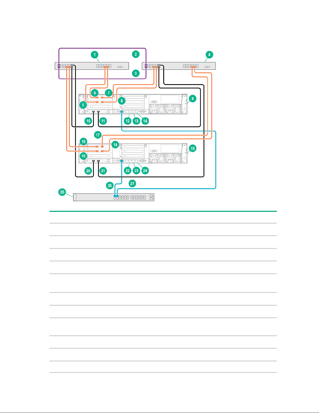
CloudSystem configuration
10 GbE Switch A (IPv6 enabled)
15
Connect Node 1, Port 4 to Switch A (IPv6
Interconnect switch links
16
Connect Node 1, Port 6 to Switch A (IPv6
Interconnect switch links
17
Connect Node 1, Port 5 to Switch B (IPv6
10 GbE Switch B (IPv6 enabled)
18
Connect Node 1, Port 3 to Switch B (IPv6
Connect Node 1, Port 4 to Switch A (IPv6
19
Node 2
Connect Node 1, Port 6 to Switch A (IPv6
20
Connect Node 2, Port 2 to Switch A (IPv6
Connect Node 1, Port 5 to Switch B (IPv6
21
Connect Node 2, Port 1 to Switch B (IPv6
Connect Node 1, Port 3 to Switch B (IPv6
22
1 GbE RJ-45 port 2
Node 1
23
1 GbE RJ-45 port 3 (not used during initial
Connect Node 1, Port 2 to Switch A (IPv6
24
1 GbE RJ-45 port 4 (not used during initial
Connect Node 1, Port 1 to Switch B (IPv6
enabled)
25
1 GbE Switch
Item Description Item Description
1
2
3
4
5
enabled)
6
enabled)
7
enabled)
8
enabled)
9
10
enabled)
11
enabled)
enabled)
enabled)
enabled)
enabled)
enabled)
(not used during initial configuration; available for
customer network)
configuration; available for customer network)
configuration; available for customer network)
Installing the HC380 appliance nodes 30
Page 31

Item Description Item Description
1 GbE RJ-45 port 2 (for connection to a
laptop or workstation for setup)
26
Connect Node 2, iLO port to 1 GbE Switch
1 GbE RJ-45 port 3 (not used during initial
network)
27
Connect Node 1, iLO port to 1 GbE Switch
1 GbE RJ-45 port 4 (not used during initial
network)
12
13
configuration; available for customer
14
configuration; available for customer
Installing the HC380 appliance nodes 31
Page 32

Configuring the system
Configuring the HC380 system
This section describes how to complete the appliance configuration steps. Before you begin, ensure that
the switches and appliance nodes have been racked and cabled per the earlier instructions, and that you
have completed the preinstallation worksheets (on page 14).
Process overview:
1. Configuring the network switches (on page 32)
2. Powering on all nodes (on page 33)
3. Configuring a laptop or workstation to access the system (on page 33)
4. Testing network connectivity (on page 34)
5. (optional) Licensing and installing NVIDIA Tesla M60 GPUs (on page 34)
6. Configuring the HC380 using OneView InstantOn
7. Installing HC380 Management UI (on page 44)
Configuring the network switches
The system uses the FlexLOM (1 or 10GbE interfaces) as well as additional 10GbE Interfaces (for
CloudSystem) for all network communication beyond the original deployment.
The switch configuration in your environment may vary. For a sample network switch configuration and
instructions on how to create the configuration, see "Appendix A: Network switch configuration (on page
85)."
General virtualization and VDI workload configurations
HC380 General virtualization or VDI solutions are supported on a flat/untagged network or a network with
tagged VLANs to segment iSCSI and vMotion traffic. The ESXi management network must always be an
untagged (pvid) network.
You may put the ESXi, vMotion, and storage networks on the same subnet, but Hewlett Packard
Enterprise recommends separate subnets or VLANs to isolate and manage the network traffic.
When using the HC380 General Virtualization or VDI solutions, the following networks and configurations
are used by the solution over the FlexLOM (1 or 10GbE) interface for each node:
• ESXi Management Network (untagged, pvid network)
• VMware vMotion Network (untagged or tagged network)
• VSA iSCSI Storage network (untagged or tagged network)
• IPv6 must be enabled for the VLANs used by the HC380
CloudSystem configuration
CloudSystem requires separate VLANs for each network. The ESXi management network must be
untagged for initial deployment and then migrated to a tagged network during the installation process. For
more information about migrating, see "Installing CloudSystem (on page 48)."
When using the CloudSystem solutions the following networks and configurations are used by the
solution over the FlexLOM, PCI Slot 2 and PCI Slot 3 (10GbE) interfaces for each node:
• HC380 ESXi Management Network/Data Center Management Network (untagged pvid network)
Configuring the system 32
Page 33

• VSA iSCSI Storage network/iSCSI Storage Network (tagged network)
• VMware vMotion Network (tagged network)
• Cloud Management Network (tagged network)
• Consumer Access Network (tagged network)
• Object Proxy Network (tagged network)
• IPv6 must be enabled for the VLANs used by the HC380
Separate subnets are required for all networks. The subnet 192.168.0.0/21 is reserved by CloudSystem
for internal purposes and cannot be changed.
Powering on all nodes
The system firmware initiates an automatic power-on sequence when the power cables are connected
and the nodes are installed. The default power setting is set to always on. Do not change the default
power setting unless instructed by Hewlett Packard Enterprise.
Before powering on the nodes, ensure that the cables are configured as recommended. For more
information, see "Cabling the system (on page 27)."
If the system does not automatically power on, you can use the following alternate methods:
• Use a virtual power button selection through iLO.
• Press and release the Power On/Standby button.
When the node goes from the standby mode to the full power mode, the node power LED changes from
amber to green. For more information about iLO, see the Hewlett Packard Enterprise website
(http://www.hpe.com/info/ilo/docs).
Configuring a laptop or workstation to access the system
Use these steps to connect an installation computer to an HC380 node and establish IPv4 network
connectivity. Windows remote desktop software is used to establish a remote desktop session on the
HC380 node.
NOTE: Instructions are provided for a Windows system. If you are using a non-Windows
system, see the appropriate documentation.
To access the system, use a laptop or workstation with a 1 GbE port that can run Microsoft Windows
Remote Desktop Services (for example, mtsc.exe).
1. Disconnect the laptop or workstation from all networks.
2. Connect the 1 GbE laptop or workstation port to the system using a Cat5E cable.
Configuring the system 33
Page 34
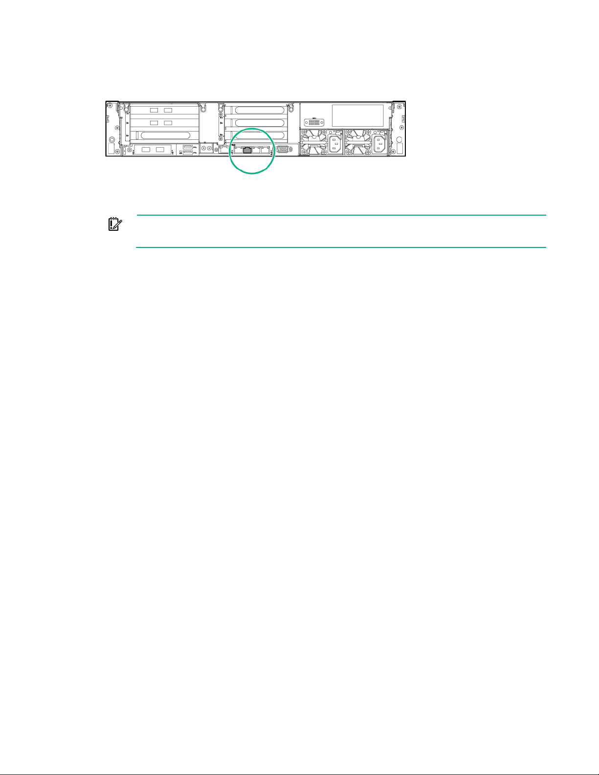
Do not configure a laptop or workstation with an IP address of 192.168.42.100
Use the following illustration to locate the correct port. Your rear components may vary from what is
shown.
3. Configure the laptop or workstation port to use the static IP address 192.168.42.99 with subnet
mask 255.255.255.0 (a gateway address is not required).
IMPORTANT:
or greater. These addresses might be used by the appliance.
a. Access the Network and Sharing Center from the Windows desktop.
b. Navigate to the available network connections.
c. Right-click the appropriate NIC and select Properties.
d. Select Internet Protocol Version 4, and then select Properties.
e. Select Use the following IP address and enter the IP address 192.168.42.99, and subnet
mask, 255.255.255.0. Click OK.
4. From the laptop or workstation, locate and select Remote Desktop Connection from the Start
menu. In the Computer field, enter 192.168.42.100, and then click Connect.
5. In the Windows Security dialog box, enter the credentials:
o User name: administrator
o Password: HyperConv!234
Testing network connectivity
Before continuing to configure the HC380, you can test your network setup to ensure that IPv6 is enabled
on your network between your HC380 nodes. To ensure IPv6 is configured properly, perform the following
test.
1. (Optional) Test the IPv6 connectivity to the iLO of each HC380 node.
This test may not work if the switch your iLO is connected to does not support IPv6.
2. Test the IPv6 connectivity to the VMware ESXi hosts from the node you plan to use as the
management VM.
For more information on each of these tasks, see "Validating the switch configuration (on page 96)."
Licensing and installing NVIDIA Tesla M60 GPUs
Use this section if you use the VDI configuration of the HC 380 and plan to use NVIDIA Tesla M60 GPUs.
The procedures in this section are used to install the GPU configuration utility, verify that the GPU mode is
set to Graphics, and install the NVIDIA drivers on the HC 380 vSphere nodes.
The procedures in this section must be performed before configuring the HC 380 using OneView
InstantOn.
Configuring the system 34
Page 35

If your HC 380 purchase includes NVIDIA Tesla M60 GPUs, you must visit the NVIDIA website
(http://www.nvidia.com/object/nvidia-grid-buy.html) to register your product and download the
following:
• 90-day trial license
• Preferred Solution Provider list
• NVIDIA GRID software
• GPU mode change utility
• License server software
• Documentation
To maintain full functionality of your GPU after the 90-day trial license expires, you must purchase a
license from a Preferred Solution Provider. Locate a Preferred Solution Provider using the provider list.
For NVIDIA GRID quickstart documentation and resources, visit the NVIDIA website
(http://www.nvidia.com/object/grid-enterprise-resources.html).
Installing the NVIDIA GPU mode change utility on the vSphere host
Use the following steps to install the GPU mode change utility that is used to verify the NVIDIA GPU
mode.
1. Download the GPU mode change utility by registering for the NVIDIA Grid software from the NVIDIA
website (http://www.nvidia.com/object/nvidia-grid-buy.html).
2. On the vSphere host, extract the GPU mode change utility from
NVIDIA-gpumodeswitch-2016-04.zip.
3. Copy the NVIDIA-GpuModeSwitch-1OEM.600.0.0.2494585.x86_64.vib to the root of the vSphere
host.
4. Run the following command to put the HC 380 node into Maintenance mode.
# esxcli system maintenanceMode set -e true -t 0
5. Run the following command to install the GPU mode change utility:
# esxcli software vib install --no-sig-check -v
/NVIDIA-GpuModeSwitch-1OEM.600.0.0.2494585.x86_64.vib
Use the no-sig-check option since the Software acceptance level is set to PartnerSupported by
default.
6. Run the following command to remove the vSphere host from Maintenance mode.
# esxcli system maintenanceMode set -e false -t 0
7. Wait for the host to exit Maintenance Mode and then run the following command to reboot the
vSphere host.
# reboot
Verifying the NVIDIA GPU mode
On the vSphere host, run the following command to list the current GPU mode:
# gpumodeswitch --listgpumodes
If the GPU mode is set to Graphics, proceed to the next task "Installing NVIDIA GRID Manager software
on vSphere (on page 36)."
If the GPU mode is not set to Graphics, perform the following steps to change the GPU mode.
1. Run the following command to switch the mode:
Configuring the system 35
Page 36

# gpumodeswitch --gpumode graphics
2. Type y to confirm updating all graphics adapters.
3. Run the following command to reboot the vSphere host.
# reboot
4. Verify that the GPU Mode is set to Graphics by running the following command:
# gpumodeswitch --listgpumodes
Installing NVIDIA GRID Manager Software on vSphere
1. Obtain the nVIDIA GRID Manager software by visiting the NVIDIA website
(http://www.nvidia.com/object/nvidia-grid-buy.html).
2. Extract the GPU configuration utility from NVIDIA-GRID-vSphere-6.0-361.45.09-362.56.zip.
3. Copy the NVIDIA-vGPU-VMware_ESXi_6.0_Host_Driver_361.45.09-1OEM.600.0.0.2494585.vib
to the root of the vSphere host.
4. From the vSphere host console (or SSH), run the following command to put the HC 380 node into
Maintenance mode.
# esxcli system maintenanceMode set -e true -t 0
5. Run the following command to install the NVIDIA GRID manager software.
# esxcli software vib install -v /
NVIDIA-vGPU-VMware_ESXi_6.0_Host_Driver_361.45.09-1OEM.600.0.0.2494585.v
ib
6. Run the following command to reboot the vSphere host.
# reboot
7. Run the following command to remove the vSphere host from Maintenance mode.
# esxcli system maintenanceMode set -e false -t 0
8. Run the following command to verify that NVIDIA GRID Tesla M60 graphics adapters are present
and installed.
# nvidia-smi
Configuring the HC380 using OneView InstantOn
Guidelines for using OneView InstantOn
OneView InstantOn is the automated deployment tool that guides you through the steps to configure your
HC380 appliance. Following successful completion of this configuration, you then perform the initial
HC380 Management UI configuration before you can begin deploying virtual machines. After you add all
the configuration information in OneView InstantOn, you can deploy the system.
Use the following guidelines for using OneView InstantOn:
• Before launching OneView InstantOn, verify that your management VM contains the folder
C:\ProgramData\Hewlett-Packard\StoreVirtual\InstantOn\PostDeployment. Contact Hewlett
Packard Enterprise Support if it does not.
• While OneView InstantOn is running, do not run anything else on the system including running
Windows Update and configuring proxies.
• Do not run OneView InstantOn while performing an HPE LeftHand OS upgrade.
• OneView InstantOn allows you to perform initial deployments and expansions of existing
deployments. Following a successful deployment, you can launch the tool to expand the system or
view the settings, but you are not allowed to change the settings or redeploy the system.
Configuring the system 36
Page 37

• To complete the steps in this section, use the information you entered in the preinstallation
If you select Remote, ensure that vCenter is not running on the Management VM of another
that the VMware vCenter user has access to the OneView for
VMware vCenter Storage Administrator Portal. Otherwise, OneView InstantOn deployment
worksheets (on page 14).
• After you successfully connect using a laptop ("Configuring a laptop or workstation to access the
system" on page 33), OneView InstantOn will automatically start. If it does not, navigate to the
desktop and click the OneView InstantOn shortcut to start the application.
• Tool tips and error information are available when you hover in a text box on a screen in OneView
InstantOn. The information might take a few seconds to display.
• The OneView InstantOn version shown in the figures in this document may be different from what is
installed on your system. The content of the screens is the same.
• To navigate through OneView InstantOn, you can click Next, or click a location in the left navigation
pane. The information that you enter on a screen is automatically saved. Before you click the Deploy
button, you can go back to any screen and change or add information.
• If the system seems unresponsive, do not attempt to restart it. If processing is occurring, allow it to
complete.
Completing the Introduction screen
1. Review the information on the screen. If you have not already done so, complete the worksheets in
the section "Preinstallation worksheets (on page 14)."
2. On the Introduction screen, accept the End User License Agreements, and then click Next.
Completing the vCenter screen
On the vCenter screen, select the instance of OneView for VMware vCenter that you will use:
• Select Local if the system will use a local (included) copy of vCenter.
• Select Remote if the system will connect to vCenter currently running on another server. For more
information about a Remote vCenter installation, see "Appendix F: Remote vCenter setup (on page
107)."
NOTE:
•
HC380 system. Otherwise, problems could occur during deployment.
• If you select Remote, ensure
will not complete successfully.
Use one of the following sections, depending on whether you select Local or Remote.
If you select Local:
1. In the Set Key field, enter the VMware vCenter Server 6 Standard license and click Apply.
2. In the Cluster field, specify the datacenter and cluster on OneView for VMware vCenter that will be
• CloudSystem supports a local vCenter deployment only.
IMPORTANT:
• You cannot change the datacenter or cluster name after completing a new system
installation or expansion.
• Ensure that you follow VMware naming convention when creating datacenter and cluster
names. If special characters are used in the names, OneView InstantOn will hang.
used for the system hosts and VSA storage by performing one of the following:
o Click the down arrow to select it from the drop-down list.
Configuring the system 37
Page 38

o
Create a new datacenter and cluster:
i. Click New.
The Create New vCenter Datastore/Cluster window opens.
ii. Enter a new datacenter and cluster name.
iii. Click Create.
iv. Select this cluster name in the Cluster field on the vCenter screen by clicking the down arrow
and selecting it from the drop-down list.
3. Click Next to continue to the Health screen.
If you select Remote:
1. Under Access, enter the following information:
o IP address of the remote vCenter server
o the VMware vCenter credentials (username and password)
o SSO default port
2. In the Management VM ESXi Connectivity section, enter the IPv4 address (subnet mask and
gateway) for the Management VM on the system.
OneView InstantOn verifies that the remote server can be accessed and that the remote instance of
OneView for VMware vCenter is installed at the correct, minimum version. The health icon next to
Access changes to green when verifications have completed successfully. No license is required for
OneView for VMware vCenter.
Your switched network may require you to complete the Management VM ESXi Connectivity section
before the vCenter verification in the Access section is marked successful.
3. After the Access and Management VM ESXi Connectivity sections report green status, you can
apply a license for the remote instance of OneView for VMware vCenter if it is not already licensed. If
it is already licensed, skip this field.
4. In the Cluster field, specify the datacenter and cluster on OneView for VMware vCenter that will be
used for the system hosts and VSA storage by performing one of the following:
o Select the datacenter and cluster by clicking the down arrow.
o Create a datacenter and cluster:
i. Click New.
The Create New vCenter Datastore/Cluster window opens.
ii. Enter a datacenter and cluster name.
iii. Click Create.
iv. Select this cluster name in the Cluster field on the vCenter screen by clicking the down arrow
and selecting it from the drop-down list.
IMPORTANT:
• You cannot change the datacenter or cluster name after completing a new system
installation or expansion.
• Ensure that you follow VMware naming convention when creating datacenter and cluster
names. If special characters are used in the names, OneView InstantOn will hang.
5. Click Next to continue to the Health screen.
Completing the Health screen
1. On the Health screen, verify that the health is green for all system nodes.
If the health is red, verify that the cabling is correct.
Configuring the system 38
Page 39
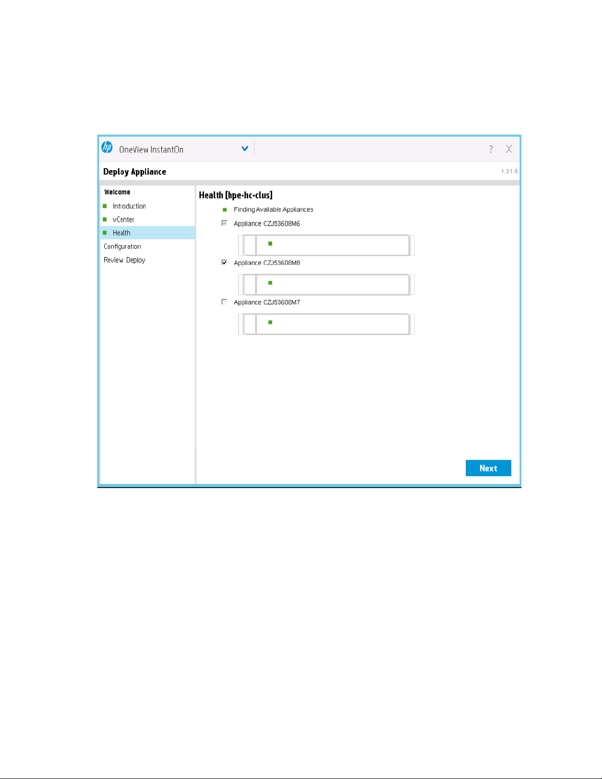
You can install multiple systems at the same time. Up to sixteen systems can be installed
simultaneously.
By default, the system from which you are accessing the Management VM to complete deployment
is selected.
2. Select the systems you want to install.
3. Click Next to continue to the IP assignments screen.
Completing the IP Assignments screen
1. On the IP Assignments screen, enter the appropriate network settings, using the information
collected in the preinstallation worksheets (on page 14).
You can provide only the starting IP address in the range, and OneView InstantOn automatically
assigns the remaining, contiguous IP addresses.
Configuring the system 39
Page 40
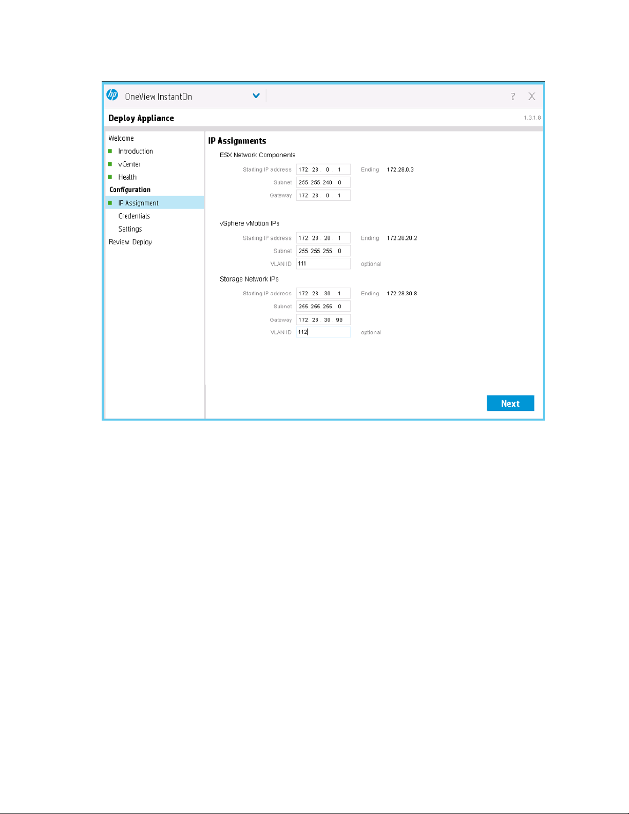
If you selected Remote on the vCenter screen ("Completing the vCenter screen" on page 37), the
Starting IP address field is pre-populated with the IP address you entered on that screen.
2. Click Next to continue to the Credentials screen.
Completing the Credentials screen
1. On the Credentials screen, enter the preferred StoreVirtual credentials.
You use these credentials to access the StoreVirtual Centralized Management Console when you
apply the StoreVirtual licenses.
Credential requirements:
o User name:
— Must contain 3–30 characters
— Must begin with a letter (a-z, A-Z)
— May contain ASCII letters, numbers, asterisks (*), underscores (_) or hyphens (-)
— Cannot contain the equal sign (=)
o Password:
— Must contain 5–40 characters
— May contain most ASCII characters, UTF-8 characters, and the multi-byte character set
— Cannot contain spaces, periods (.), colons (:), semi-colons (;), forward or backward slashes (\
/), commas (,), single quote (‘), or equal sign (=)
Configuring the system 40
Page 41

NOTE: You can change these credentials later using the StoreVirtual Centralized
Management Console.
2. Click Next to continue to the Settings screen.
Completing the Settings screen
Use the information collected in the preinstallation worksheets (on page 14) to complete the fields of the
Settings screen.
1. In the General Settings section, enter the following information:
o preferred storage system name
o storage network domain name server address
o network time protocol server address
2. In the Mail Settings section, enter the following information:
o storage network mail server and port
o sender email
o recipient email
3. If you are deploying a 2-node system, the Quorum setting field displays. Enter an NFS file share
name.
Configuring the system 41
Page 42
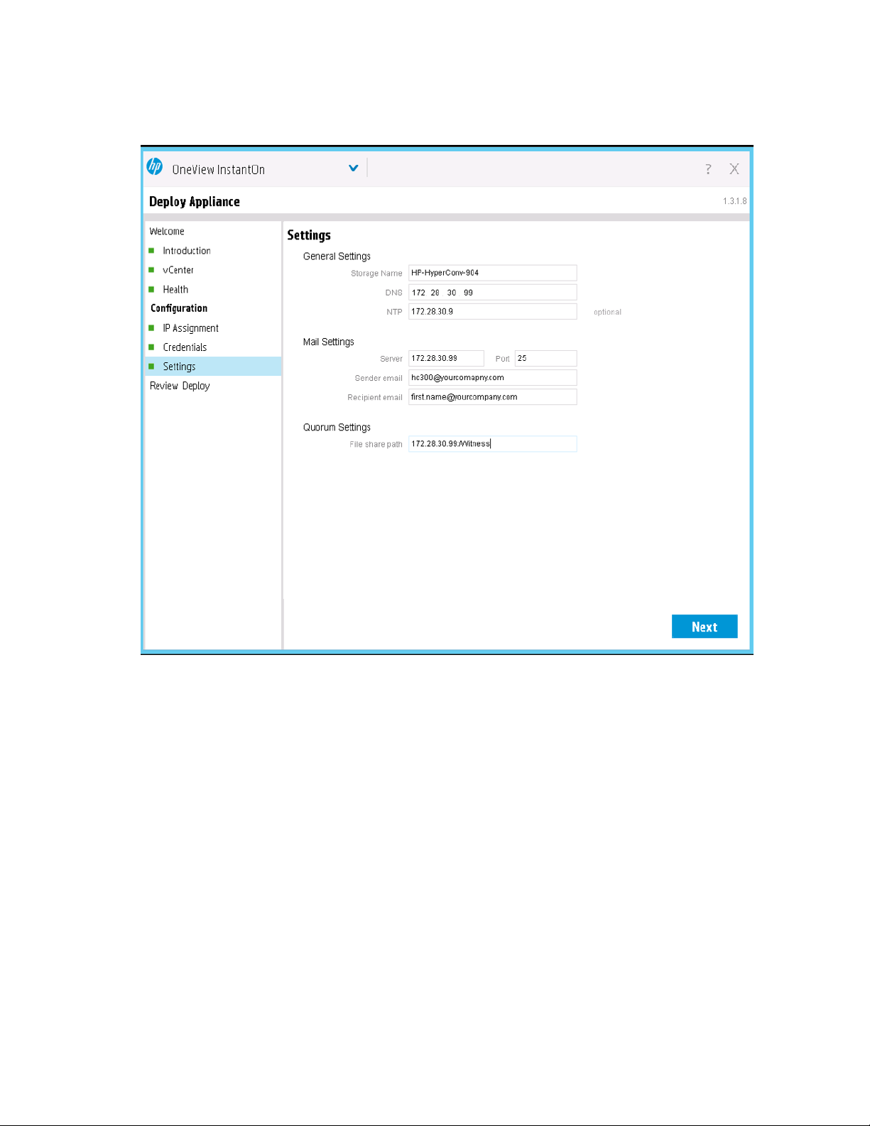
If you prefer to use a VSA Failover Manager, enter an invalid NFS share IP address, and OneView
InstantOn will create a Virtual Manager that can be configured in the StoreVirtual CMC as a
post-deployment step. For more information, see "Appendix G: Management group quorum
consideration (on page 109)."
4. Click Next to continue to the Review Configuration screen.
Completing the Review Configuration Screen
1. On the Review Configuration screen, ensure the information that you entered is correct.
Configuring the system 42
Page 43
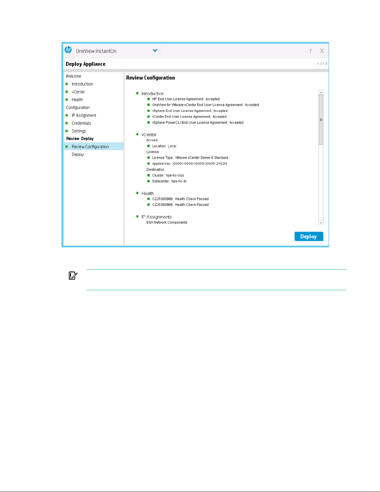
If you need to make changes, go back using the links in the left navigation pane.
2. When you are ready to proceed, click Deploy.
Be aware that if you are deploying multiple systems, the time to complete deployment increases.
IMPORTANT: Do not close OneView InstantOn during the deployment process. If the
deployment does not complete or hangs, see "Troubleshooting (on page 73)."
When the deployment is complete, the Next Steps screen appears.
Completing the Next Steps screen
On the Next Steps screen, start the process of applying licenses. To view help documentation and
complete the installation with fully licensed VSAs, you must have internet access.
VMware software
The VMware vSphere license that ships with each HC380 node is a trial license that is valid for 60 days
from the date on which the node ships from the factory. Apply a purchased license before the trial license
expires, or restrictions will occur.
To apply your license for each of the ESXi nodes, use the following steps.
1. Launch vCenter using the link Launch vCenter Web Client under the section License VMware
software.
2. Log in using your vCenter credentials. Use vCenter credentials only; do not use a Windows account.
For local vCenter, use the default credentials:
o user name: [email protected]
o password: HyperConv!234
Configuring the system 43
Page 44

If you need the licensing links again, restart OneView InstantOn, and the Next Steps
account that is between 8 and 50 characters. Enter the new password carefully. If you mistype
Before beginning this step, launch vCenter to determine if a reboot is required. Also, check
3.
Apply the VMware vSphere host licenses for each ESXi host using the following steps:
a. In the Administration section, select Licensing > Licenses.
b. Select the Licenses tab, and click Create New Licenses (green plus icon).
c. In the Enter license keys page, type or copy and paste a license key.
d. Click Next and follow the onscreen instructions.
e. On the Assets tab, select Hosts.
f. Select the host (or Shift+click to select multiple hosts), right-click, then select Assign License.
g. In the Assign License dialog, select the license you entered in step c and click OK.
After you apply the license to a vSphere host, the Action field for the host changes to a green
check box.
StoreVirtual
The StoreVirtual VSA license that is initially installed with each HC380 node is a trial license that is valid
for 60 days from the date on which the deployment is complete. You must apply the StoreVirtual VSA
license that is included in your HC380 purchase before the trial license expires, or restrictions will occur.
Use the following steps to obtain the StoreVirtual VSA license key from the Hewlett Packard Enterprise
Licensing Portal and apply it using the StoreVirtual Centralized Management Console.
1. Under "License StoreVirtual VSAs" on the Next Steps screen, click Launch the HPE Licensing
Portal (https://myenterpriselicense.hpe.com).
2. After you log in to the Hewlett Packard Enterprise Licensing Portal, use the StoreVirtual VSA MAC
addresses under the Feature Key heading on the Next Steps screen to obtain license keys:
a. Copy the MAC address by right-clicking the screen on top of the value that you want to copy and
selecting copy from the context menu.
b. Paste the information into a text editor.
c. Copy and paste the information from the text editor into the Hewlett Packard Enterprise licensing
portal.
3. Under "Manage advanced StoreVirtual features" on the Next Steps screen, click Launch the HP
StoreVirtual Centralized Management Console.
4. Enter the license keys you obtained from the Hewlett Packard Enterprise licensing portal.
For more information about StoreVirtual licensing, see “Registering advanced features” in HPE
StoreVirtual Storage User Guide found on the Hewlett Packard Enterprise website
(http://www.hpe.com/storage/docs/storevirtual).
NOTE:
screen automatically opens.
5. After you complete applying the licenses, click Finish.
Installing HC380 Management UI
IMPORTANT: In this procedure, you specify a new password for the HC380 administrator
and do not recall what you entered, the user interface is unusable.
NOTE:
• Accessing HC380 Management UI requires the Mozilla Firefox web browser.
•
for any errors with the high availability configuration. For more information about resolving
the errors, see the steps for resolving HA errors in "vSphere HA errors."
Configuring the system 44
Page 45
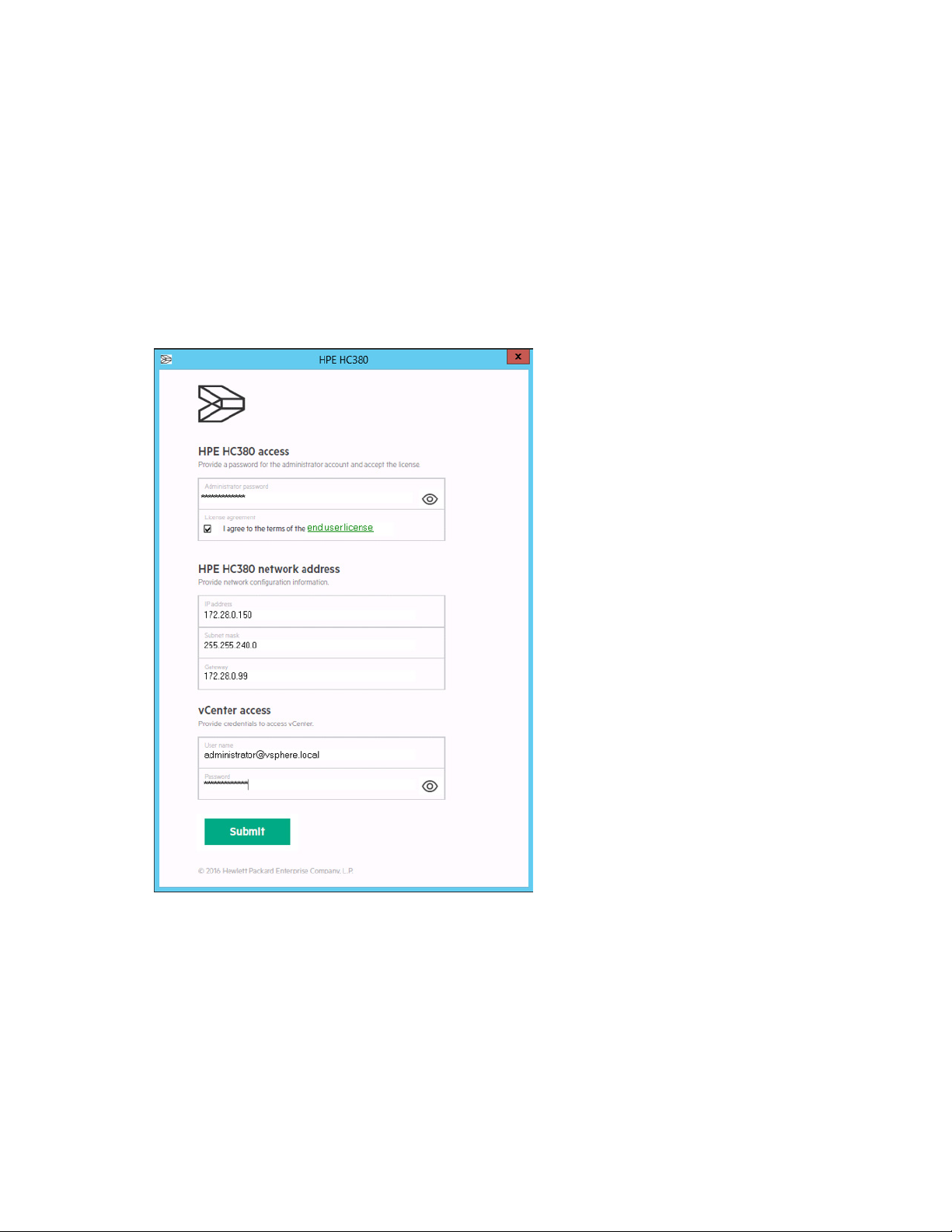
Following a successful configuration using OneView InstantOn, you are prompted to install HC380
Management UI. If you do not receive a pop-up window, check the task bar to see if the window appears
minimized. If so, maximize the window.
The HC380 Management UI deploys and configures OneView as a part of its first-time setup. It does not
support using an already configured Oneview appliance.
1. When the configuration dialog appears, provide a password for the administrator account (between
8 and 50 characters long) and accept the end-user license agreement.
2. Specify the network addresses to be used by HC380 Management UI.
a. Enter an unused IP address into the IP address field.
b. Enter the subnet mask value into the Subnet mask field.
c. Enter the gateway value into the Gateway field.
3. Provide the vCenter administrator username and password.
4. Click Submit.
You may have to wait several minutes, up to 60 minutes or longer, depending on how many nodes
are being deployed. The user interface may seem unresponsive, but you must allow the processing
to continue. Do not attempt to close the windows by clicking the x button.
After several minutes, a dialog appears that notifies you that the network configuration is complete
and provides a hypertext link to HC380 Management UI.
Configuring the system 45
Page 46

Completing the initial HC380 Management UI configuration
Configuring the settings
Process overview:
1. Performing the initial HC380 Management UI setup (on page 46)
2. Configuring LDAP or Active Directory (on page 47)
Performing the initial HC380 Management UI setup
3. Creating datastores
Most of the setup values are populated during the configuration using the OneView InstantOn tool, and
you can use the Settings area in HC380 Management UI to verify or update the values.
1. Using Mozilla Firefox, log into HC380 Management UI using Administrator and the new password
that you set in the step "Installing the HC380 Management UI."
A new screen appears to notify you that your HC380 is ready to be shaped.
2. Click Setup.
The Setup screen appears.
3. Click the pencil icon for the Identity section.
4. Provide the Embedded OneView IPv4 address for the OneView configuration.
This address was collected in the preinstallation worksheets (on page 14).
5. Verify and update, as needed, the values in the other fields, then click OK.
6. Click the pencil icon for the vCenter section.
7. Type the vCenter IP address and click Connect.
This address was configured by OneView InstantOn and shown on the Next Steps screen.
8. Accept Trust and click OK.
9. To connect the HC380 to an LDAP server or Active Directory server, click the pencil icon for the
Directory section and see "Configuring LDAP or Active Directory (on page 47)."
10. Click Setup in the Nodes section.
11. Specify the iLO credentials and iLO passwords for each hypervisor host, as shown in the
pre-installation worksheet. Ensure that the iLO matches the correct host.
If your environment uses common credentials for iLO, provide the common user name and
password and enable each host to use the common credentials.
12. Click OK.
13. Click Submit.
Completing the initial HC380 Management UI configuration 46
Page 47

Configuring LDAP or Active Directory
•
•
•
•
•
•
•
•
•
•
•
•
•
•
•
HC380 Management UI, when used in conjunction with LDAP or AD, can restrict users so that they only
see their own VMs. If HC380 is not configured with LDAP or AD, this functionality is not available.
If the HC380 is configured with LDAP or AD, use the following steps to connect to an LDAP or AD server:
1. Click Connect in the Directory section.
2. Select LDAP for a Linux server or Active Directory for a Windows server.
3. Provide the fully qualified domain name or IP address for the LDAP or Active Directory server host
and click Connect.
HC380 appliance downloads the essential certificate.
4. Read through the certificate, and click Trust.
5. For the LDAP server, provide login credentials along with the Base Domain Name and click Verify.
Base Domain Name example: DC=hpe DC=com
6. Provide a user name and password with access to the directory and click OK.
The list of directory groups appears.
7. Click the plus sign next to each directory group to associate groups in the directory with the HC380
user roles ("User roles" on page 47).
NOTE:
• Verify connectivity between the HC380 and your AD server. For AD Certificate Services,
HC380 uses the default port (636) to connect to the AD server using SSL.
• If the directory server is added as a user in the registered groups, do not prefix the domain
name before the username (domainname\username).
User roles
Before using the system, Hewlett Packard Enterprise recommends that the following user groups are
added to the Active Directory/LDAP and users added to each group. For information about adding the
user groups to your server, see the documentation for your server.
The following table defines the list of user groups and the access rights of each group.
User Access
Infrastructure Administrator
Virtual Administrator
Virtual User
Read-only User
System-wide configuration: view and edit, Dashboard
VM Actions: view activity
VM-Sizes: add and edit
VM- Images: add and edit
VM Actions: view activity
VM-Sizes: add and edit
VM-Images: add and edit
VM: actions
View: activity
System-wide configuration-View
Dashboard
View: activity
VM-Sizes: view
VM-Images: view
VM: view
Completing the initial HC380 Management UI configuration 47
Page 48

Installing CloudSystem
If you ordered CloudSystem, the CloudSystem installation utility is pre-installed on the system. Before you
run the installation utility, you must have successfully completed the steps to configure the HC380 using
OneView InstantOn.
The CloudSystem installer assumes the following:
• The HC380 system has not been modified (networking, storage, etc.) since the OneView Instant On
deployment was completed.
• The user has an understanding of the CloudSystem networking requirements and has completed
HPE Helion CloudSystem 9.0 Network Planning Guide found on the Hewlett Packard Enterprise
website (http://www.hpe.com/info/CloudSystem/docs).
• The preinstallation worksheet ("CloudSystem" on page 18) has been completed for CloudSystem.
• Networking configurations in the top-of-rack (TOR) switches have been completed. If the Data
Center Management (DCM) network VLAN is not plumbed through the top-of-rack switches, then
during the installation process it is likely communication with vCenter or ESXi hosts will be lost and
the installation process will fail.
• The MySQL JDBC driver has been downloaded and accessible from the management VM.
• Each ESXi server has SSH enabled.
Limitations
• Only local vCenter (running at the HC380 Management VM) is supported for CloudSystem
installation. The installation process is expecting specific free physical network interface cards
(NICs) on the ESXi hosts managed by vCenter.
• The ESXi management network needs to reside on a VLAN-tagged network. This is a CloudSystem
requirement.
• When expanding nodes, manual steps are required when connecting to the environment enabled for
CloudSystem. The installation process migrates the management network from a flat to
VLAN-tagged network, and is migrated from a standard vSphere switch to a distributed vSphere
switch. During the expansion process, before the OneView InstantOn expansion process is run on
new ESXi hosts, the networking needs to be migrated in a similar process.
Installing CloudSystem 48
Page 49

Running the installation utility
Overview
The CloudSystem installation process can take several hours to complete, so adequate preparation can
help limit the amount of re-work that will need to be done. This guide assumes that the user is familiar with
the overall installation process as referenced in HPE Helion CloudSystem 9.0 Installation Guide, and the
background information provided in HPE Helion CloudSystem 9.0 Administrator Guide, and HPE Helion
CloudSystem 9.0 Network Planning Guide. These guides can be found on the Hewlett Packard Enterprise
website (http://www.hpe.com/info/CloudSystem/docs).
For the HC 380, CloudSystem can be installed in a completely hands-off manner after the pre-requisite
data is provided by the user. The CloudSystem deployment process will spawn a process that performs
the following:
• modifies vCenter networking for the ESXi hosts
• creates an additional compute cluster in vCenter
• allocates storage from VSA, deploys CloudSystem
• configures some of the networking components inside CloudSystem
Before beginning the installation process, you should have completed the preinstallation worksheet for
CloudSystem ("CloudSystem" on page 18).
Additional post-deployment options are available to upgrade to CloudSystem 9.01 and 9.02 and change
CloudSystem passwords.
The installer has been designed so that it can be launched multiple times – if an error situation causes the
CloudSystem installer to fail and that situation is subsequently resolved, re-running the tool will then allow
it to pick up where it left off.
Downloading the MySQL JDBC driver
Before starting the installation, you must download the MySQL JDBC driver and have it available on your
staging environment.
1. Download the MySQL Connector/J (JDBC driver) package from the Hewlett Packard Enterprise
Website (http://www.hpe.com/support/softwaredepot). This requires a Hewlett-Packard
Enterprise Passport account.
2. Extract libmysql-java_5.1.32-1_all.deb from the zip file and add it to your staging environment.
Enabling SSH on each ESXi server
1. Using iLO, connect to the ESXi server.
2. Launch the iLO Integrated Remote Console.
3. Press F2 to access the Customize System/View Logs menu.
4. Type the username and password.
5. Access the Troubleshooting Mode Options menu.
6. Enable SSH.
7. Press Esc to exit the Troubleshooting Mode Options menu.
8. Press Esc to close the Customize System/View Logs menu.
9. Repeat these steps for each ESXi server.
Installing CloudSystem 49
Page 50

Running the installation utility
The CloudSystem installer can be launched from the management VM, by using a connected laptop or
workstation. For more information, see "Configuring a laptop or workstation to access the system (on
page 33)."
Before launching the installation utility, you should have completed the preinstallation worksheet for
CloudSystem ("CloudSystem" on page 18).
If you encounter issues during the installation process, see "Troubleshooting CloudSystem (on page 76)."
Launch the installation utility by using the CloudSystem 9.01 Installation desktop icon or by executing the
Completing the Introduction screen
file C:\Program Files\HPE\HPECS9Setup\CloudSystem9.exe.
1. On the Introduction screen, review the content and accept the vSphere PowerCLI End User License
Agreement.
2. Click Next to proceed to the Installation Options screen.
Completing the Installation Options screen
1. On the Installation Options screen, specify whether you are installing the Foundation or Enterprise
version of CloudSystem.
The Enterprise version is a superset of Foundation and includes the Cloud Service Automation and
Operations Orchestration products.
2. Specify the location of the MySQL JDBC driver by clicking Browse and selecting the location of the
libmysql-java_5.1.32-1_all.deb driver file.
Installing CloudSystem 50
Page 51

3.
Click Next to proceed to the Core VLAN IDs screen.
After installation, you have the opportunity to enter the license for the enterprise components.
Completing the Core VLAN IDs screen
1. On the Core VLAN IDs screen, provide networking VLAN IDs for each of the five CloudSystem
networks.
These values can be between 1 and 4095. The Data Center Management Network VLAN coincides
with your management network. VLANs for the Storage trunk must represent unused VLANs in your
environment. Select any non-used ID to represent these networks. The CloudSystem installation
process requires valid VLAN values and we did not want to pick arbitrary VLAN values that could
interfere with the customer’s networks.
Installing CloudSystem 51
Page 52
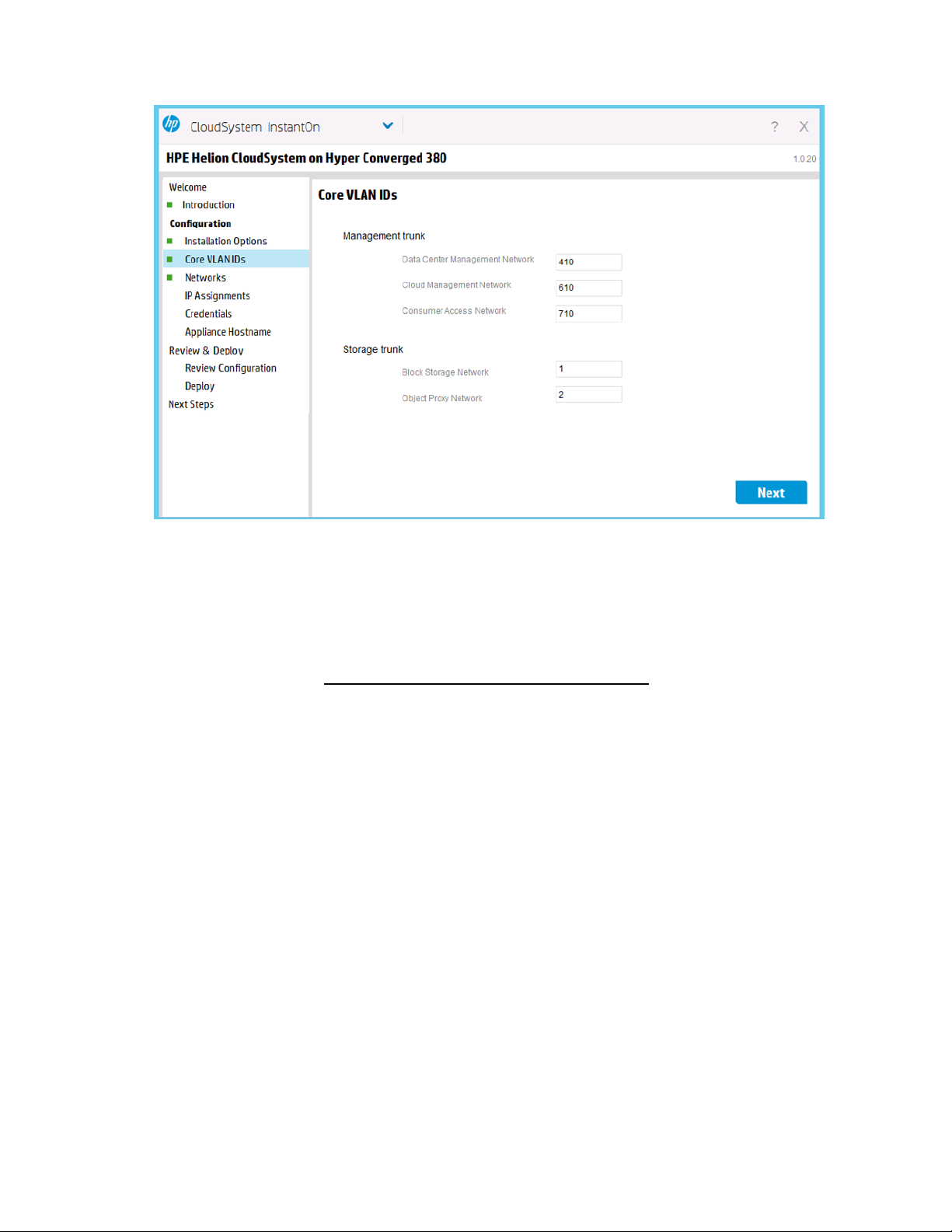
2.
Click Next to proceed to the Networks screen.
Completing the Networks screen
1. On the Networks screen, specify up to four Provider and four Tenant VLAN identifiers and the
corresponding networking subnet range (in CIDR format).
You can also specify the external networking VLAN identifier and the corresponding CIDR
networking value for the external VLAN. See HPE Helion CloudSystem 9.0 Network Planning Guide
for more details on provider and tenant networks. This guide is found on the Hewlett Packard
Enterprise website (http://www.hpe.com/info/CloudSystem/docs).
Installing CloudSystem 52
Page 53
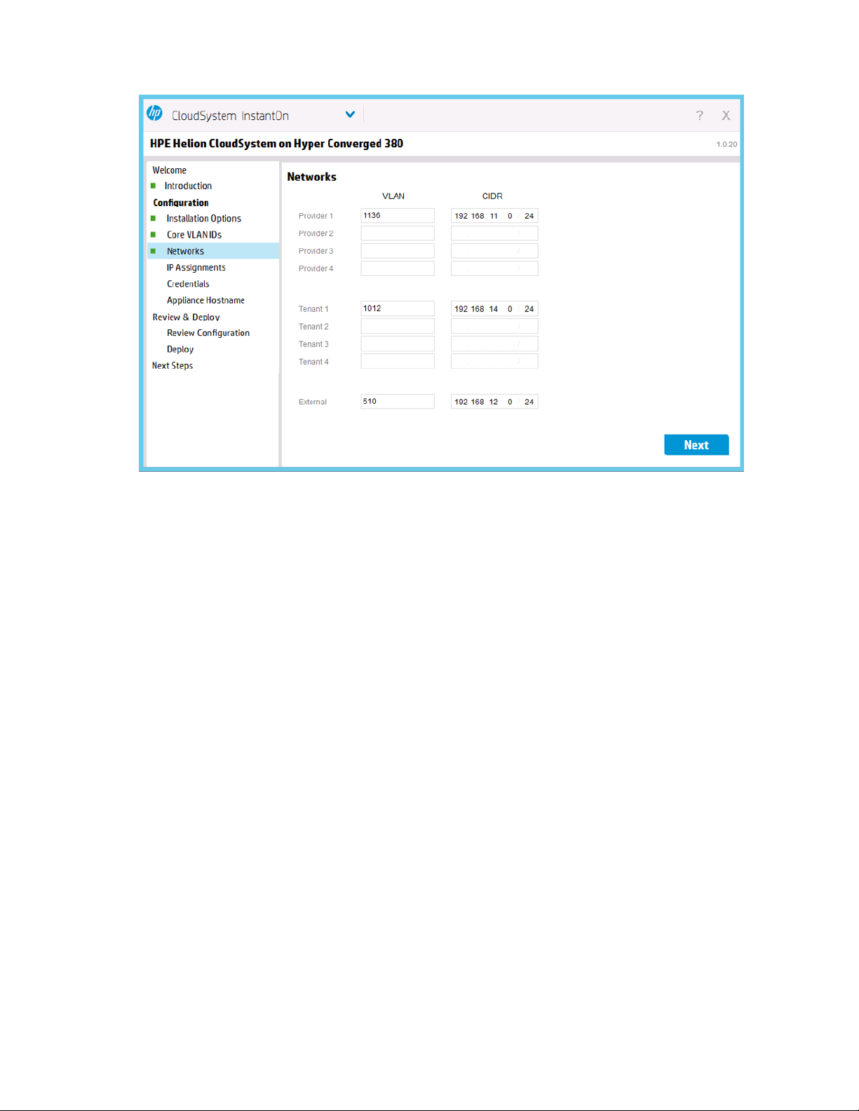
2.
Click Next to proceed to the IP Assignments screen.
Completing the IP Assignments screen
1. On the IP Assignments screen, specify the range of IP addresses used for the CloudSystem
management VMs on the Data Center Management (DCM) and Consumer Access Network (CAN)
networks.
The values for the DCM network should be on the same subnet as the networking addresses
supplied in the OneView InstantOn tool for the ESXi Network Components in the IP Assignments
("Completing the IP Assignments screen" on page 39) screen. The block storage network values are
not used by the HC380 solution though they are required by the installation process.
Installing CloudSystem 53
Page 54
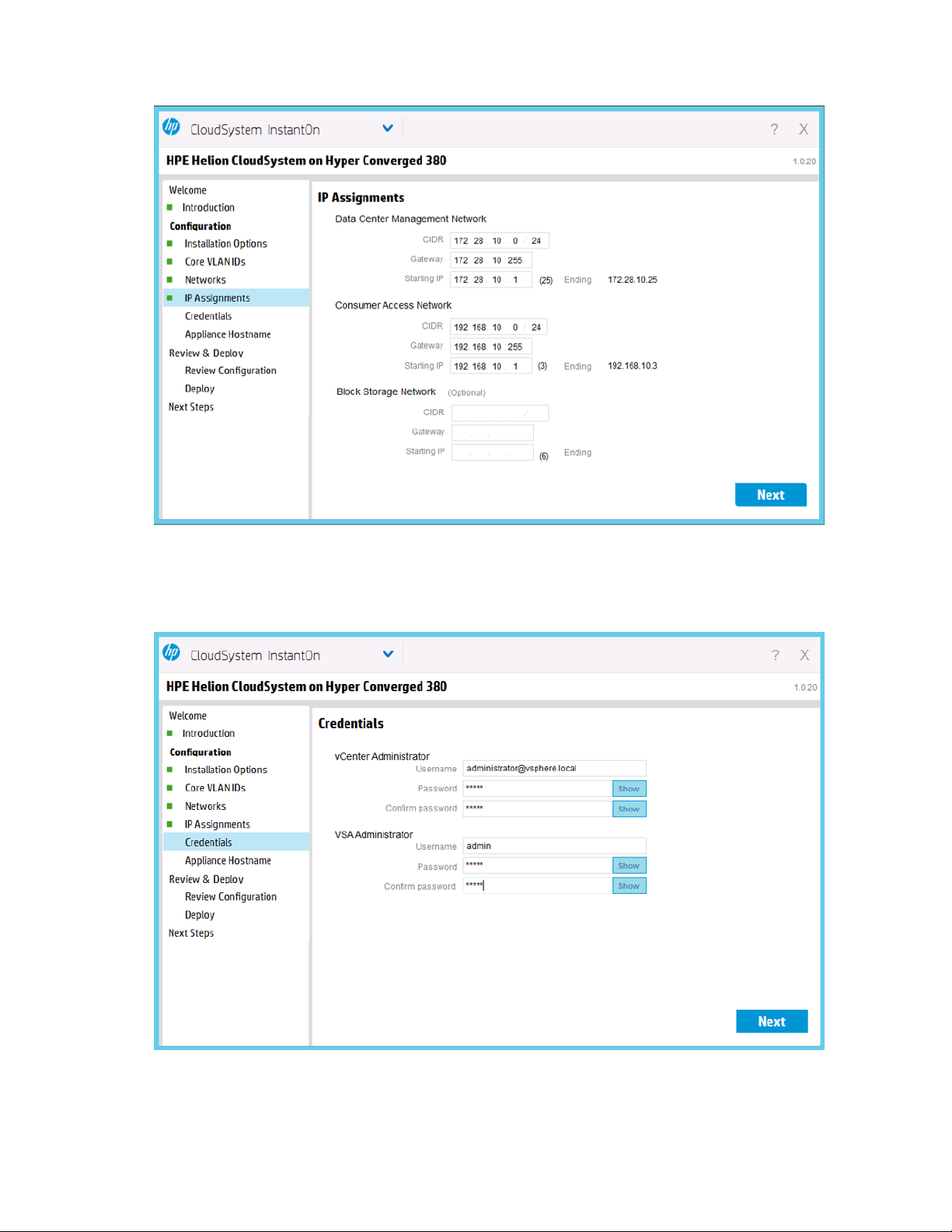
2.
Click Next to proceed to the Credentials screen.
Completing the Credentials screen
1. On the Credentials screen, provide the vCenter administrator and VSA administrator credentials.
2. Click Next to proceed to the Appliance Hostname screen.
Installing CloudSystem 54
Page 55
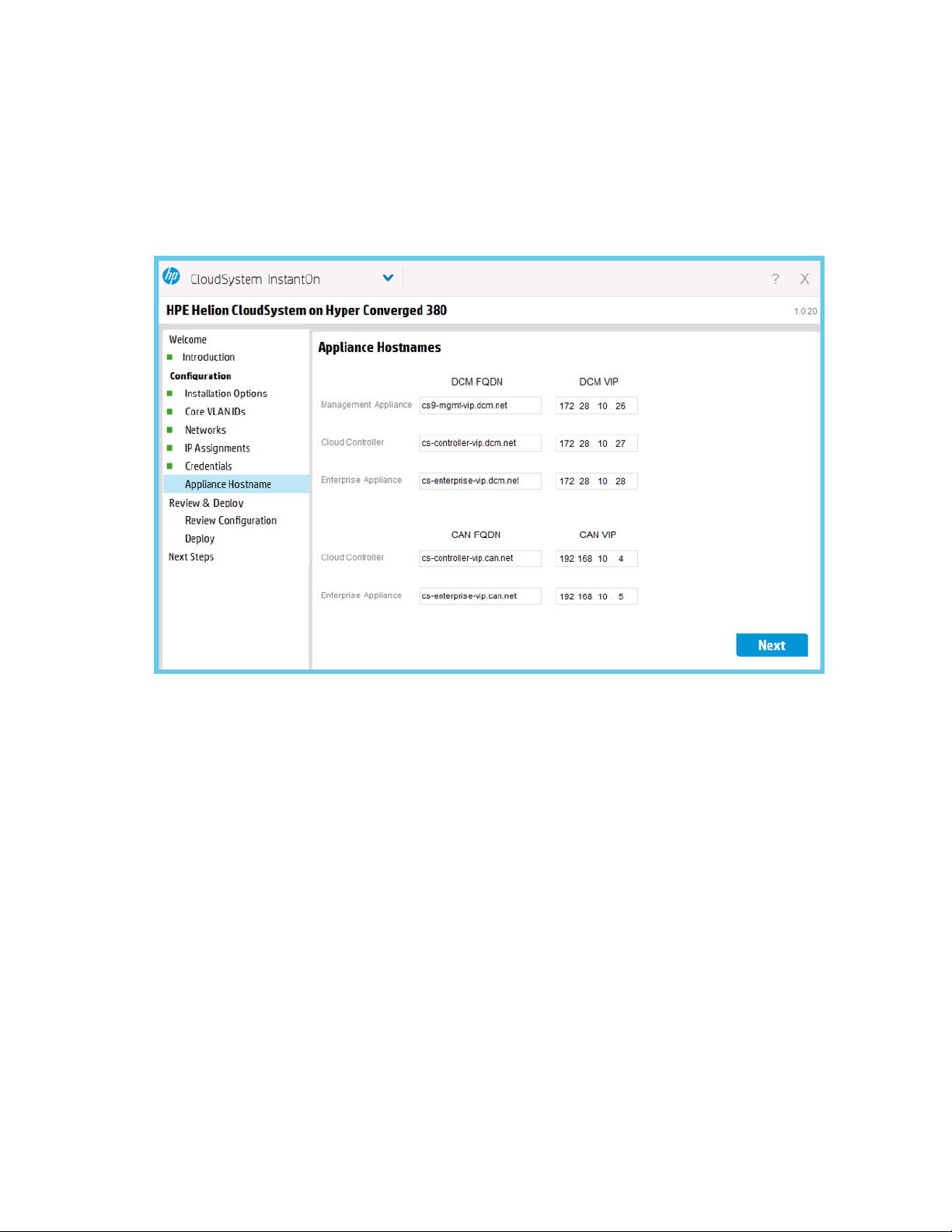
Completing the Appliance Hostname screen
1. On the Appliance Hostnames screen, specify the hostname and IP addresses needed for the
CloudSystem appliances.
Each of the major CloudSystem consoles is hosted by an appliance which allows you to specify the
hostnames and IP addresses of these appliance VMs. The DCM network and CAN network values
must be outside the range specified for the required IP addresses or specified for the DCM network
in the OneView InstantOn tool.
2. Click Next to proceed to the Review Configuration screen.
Completing the Review Configuration screen
1. In the Review Configuration screen, review all selected values and verify that no outstanding data is
missing or in a conflicted state.
Installing CloudSystem 55
Page 56

2.
When all items are denoted with a green square, click Deploy to launch the CloudSystem installer.
The Deploy screen appears to provide feedback on the installation process. A CloudSystem
Enterprise installation can take about 2 hours to complete. Details of the installation process are
shown in the Details window.
Completing the Next Steps screen
The Next Steps screen notifies you of the completion status of the installation and provides a list of items
that can be completed while additional processing occurs.
Installing CloudSystem 56
Page 57
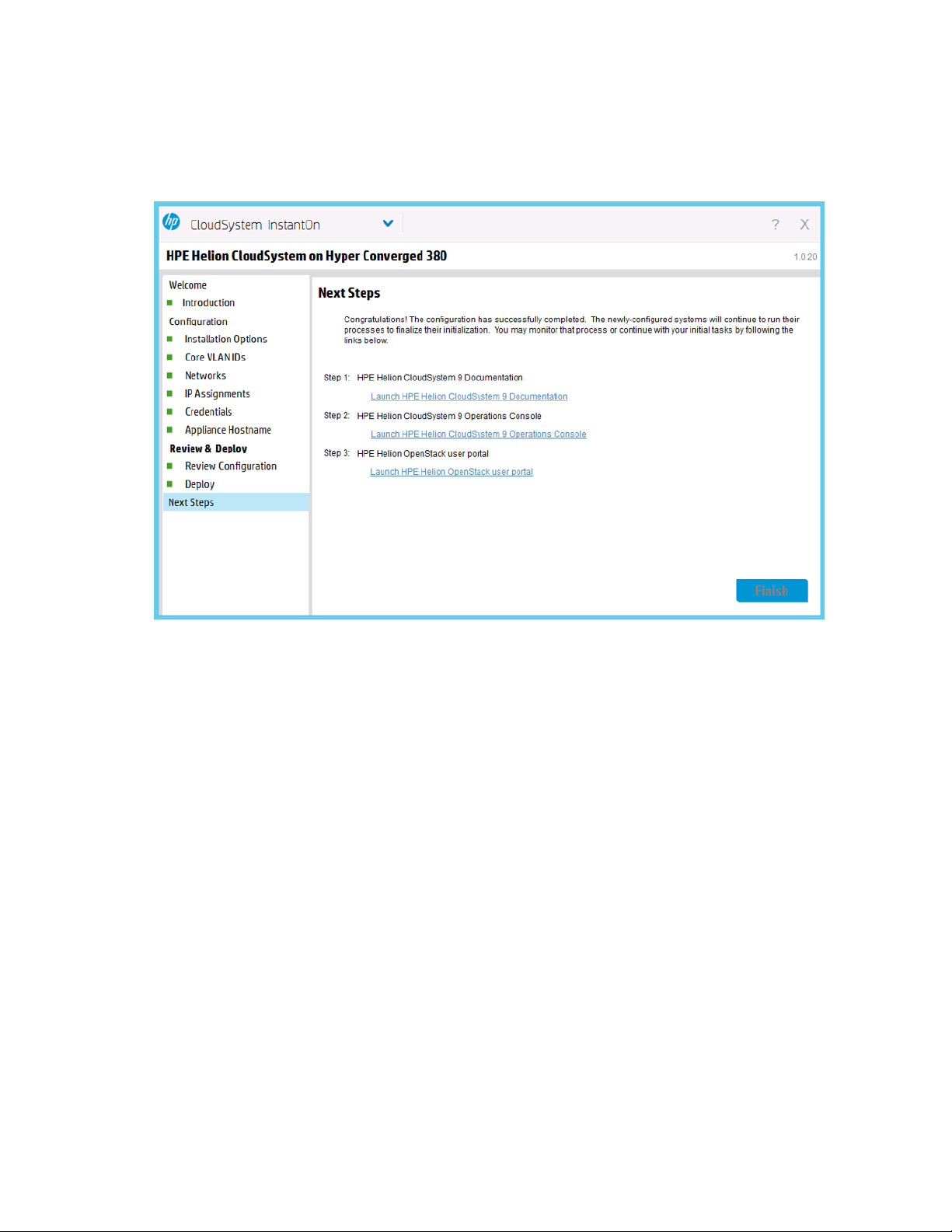
1.
Perform one or all of the following:
o View the CloudSystem 9 documentation
o Open the CloudSystem 9 Operations Console
o Open the OpenStack user portal
2. Click Finish.
After you finish using the Next Steps screen, you must disable SSH on each ESXi server before using the
product.
Datastores
The initial configuration setup and process only utilize a portion of the total available storage. To utilize the
Creating datastores
remaining storage in your HC380, you must create datastores.
1. Open a browser and navigate to the vSphere Web Client.
The login window appears.
2. Enter your user name and password for the vSphere Web Client.
3. Click Login.
Installing CloudSystem 57
Page 58

4.
To familiarize yourself with the layout of the vSphere Web Client, review the information on the
Getting Started tab.
5. In the Navigator, select vCenter.
6. In the Navigator, select Hosts and Clusters → Cluster.
7. Select the specific cluster for which you want to create a datastore.
The Summary tab for the selected cluster appears.
8. Select the Manage tab, and then select HP Management.
The Actions menu appears on the right side of the window.
The vSphere Web Client may not always refresh quickly. If you are not seeing what is expected, click
the Refresh icon in the top menu bar or the disk refresh icon on the right side of the window.
Installing CloudSystem 58
Page 59
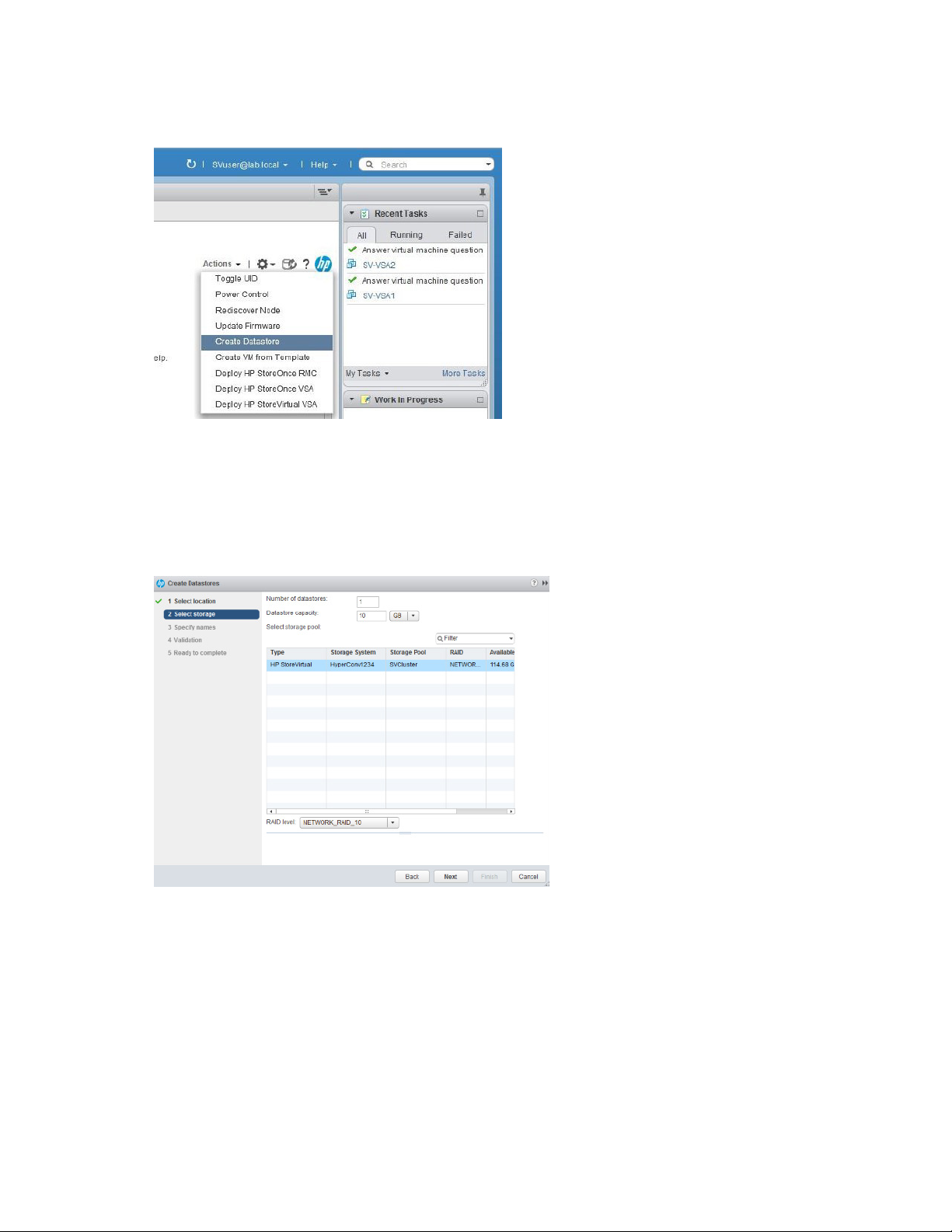
9.
From the Actions menu, select Create Datastore.
The Create Datastore wizard appears. Alternatively, right-click the cluster name and select All HP
Management Actions → Create Datastore.
10. Select the default location, and then click Next.
11. On the Select storage screen, select the applicable storage pool.
a. Select the size and number of datastores you want to create.
b. Select NETWORK_RAID_10 in the RAID level drop-down box.
12. Click Next.
The storage window appears.
13. Enter a unique name for the new datastore, and then click Next.
14. On the Validation screen, verify that the information entered is correct.
If so, click Next.
If not, click Back and return to the applicable screen to edit it.
15. On the Ready to complete window, click Finish to create the datastore.
Disabling SSH on each ESXi server
1. Using iLO, connect to the ESXi server.
2. Launch the iLO Integrated Remote Console.
Installing CloudSystem 59
Page 60

3.
Press F2 to access the Customize System/View Logs menu.
4. Type the username and password.
5. Access the Troubleshooting Mode Options menu.
6. Disable SSH.
7. Press Esc to exit the Troubleshooting Mode Options menu.
8. Press Esc to close the Customize System/View Logs menu.
Installing CloudSystem 60
Page 61

Upgrading CloudSystem
Prerequisites for upgrading cloud
You must meet the following prerequisites before beginning the update:
• You must download the file HC380-CloudSystem_9.01_Installer.zip.
• The environment variable CS9INSTALL must be set. The attributes for this variable are set during
Upgrading CloudSystem 9.0 to 9.01 and 9.02
the initial installation.
1. On the management node (on which the installation utility was run), open up PowerShell.
2. Locate the file runCS9update.ps1 by typing cd $env:CS9INSTALL. The file should be in the
location C:\ProgramData\Hewlett-Packard\StoreVirtual\InstantOn\CS9Install\Installer or
%CS9INSTALL%\Installer.
3. Run the file by typing .\Installer\runCS9update.ps1
4. In the HPE Pre-Expansion Credentials dialog, type in the cloudadmin password and click Next.
5. In the HPE Pre-Expansion Credentials dialog, type in the vCenter administrator password and click
Next.
The upgrade process proceeds and exits upon completion. You can monitor the progress of the
upgrade by accessing the log file
http://DCM_UA1_IP_address:8086/update-logs/cs-update-install-status.log.
Tenant and Provider Networking
Tenant
1. In the CloudSystem Operations Console
a. Point the browser to the URL of the Operations Console. The default IP is specified on the
Appliance Hostnames panel in the installation and deployment utility.
b. Login as admin user, using the default password unset.
c. Select Menu > Networking > Tenant Networks.
d. Add the Segmentation ID range (segmentation is the same as VLAN) with the Add Segmentation
ID Range button. If there is only one VLAN, you can enter it by itself.
2. In the Horizon console
a. Point the browser to the URL of the Horizon Console. The default IP is specified on the Appliance
Hostnames panel in the installation and deployment utility.
b. Login as admin user, default is admin/unset.
c. Select Project > Network > Networks and then + Create Network
d. On the Network tab, supply the network name (convention suggests Tenant<VLAN>). Keep
Admin State set to UP.
e. On the Subnet tab, provide the Subnet Name, Network Address CIDR, and Gateway IP. Keep IP
Version set to IPv4.
f. On the Subnet Detail tab, provide the range of network addresses.
g. Click Create when finished.
Installing CloudSystem 61
Page 62
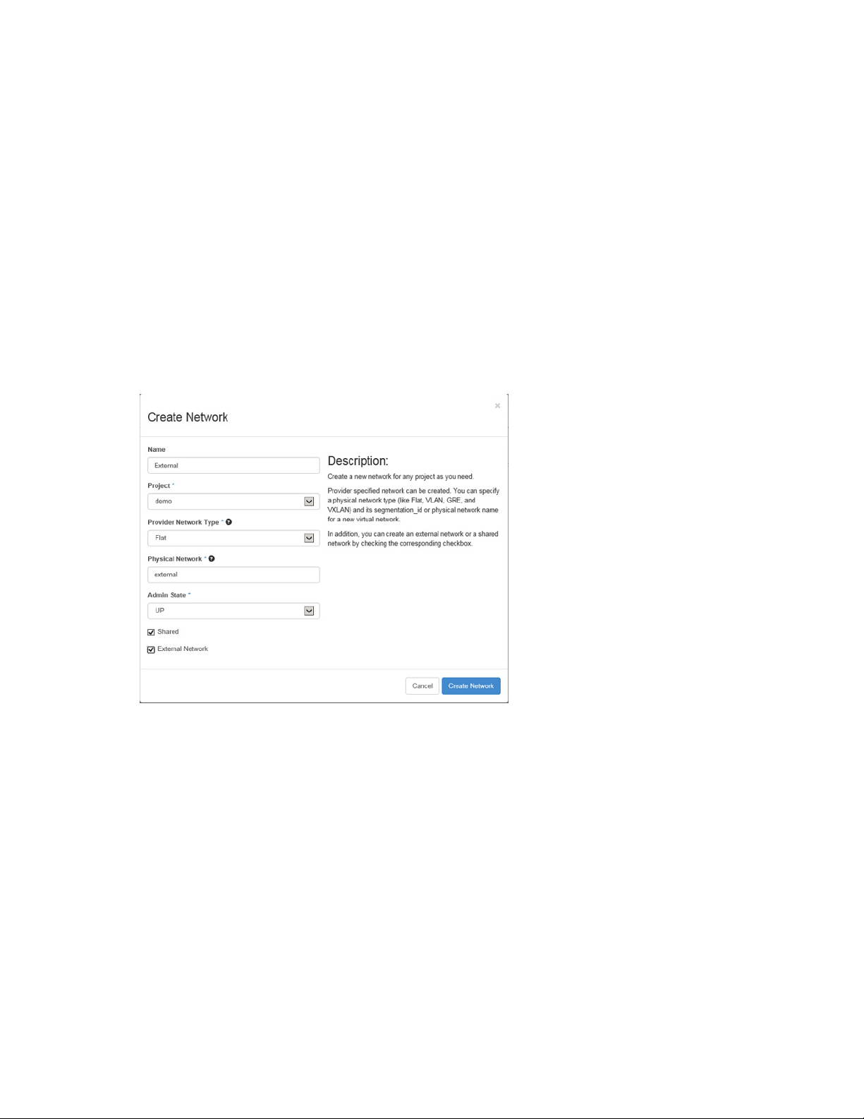
Provider
1. Launch the CloudSystem Operations Console.
2. Select Menu > Networking > Provider Networks and then Add Provider Network.
3. Supply the network name (convention suggestions Provider<VLAN>) and Segmentation (VLAN) ID.
4. Use the default demo project unless the customer has defined a different project.
5. Add the subnet details (subnet name, CIDR, gateway, & IP range (Allocation Pools)).
External
CloudSystem 9.0 supports a single external network and the respective VLAN was used during the
csdeploy setup.
1. Verify the external network is in the OneView CS9CloudData network set.
2. In the Horizon console:
a. Select Admin > System > Networks and then + Create Network.
b. Fill out the content similar to that shown below (Flat network type and external physical network).
c. Click Create Network.
d. Create the external subnet:
i. Click on the hyperlink name of the newly created external network to open the network detail.
ii. Click +Create Subnet.
iii. Provide the External network subnet name, network address CIDR, and Gateway IP.
iv. On the Subnet Detail, either enable or disable DHCP, and provide the Allocation pools, DNS
Name Server, and Host Routes.
v. Click Create.
This step will fail if the External network has not been set up with at least one IP address that can be
used as a floating IP address.
3. In the Horizon console:
a. Select Project > Compute > Access & Security.
b. Under the Floating IPs tab, click Allocate IP to Project button. This step assumes that a range of
IP addresses has already been allocated to the External network.
c. Click Allocate IP.
Installing CloudSystem 62
Page 63
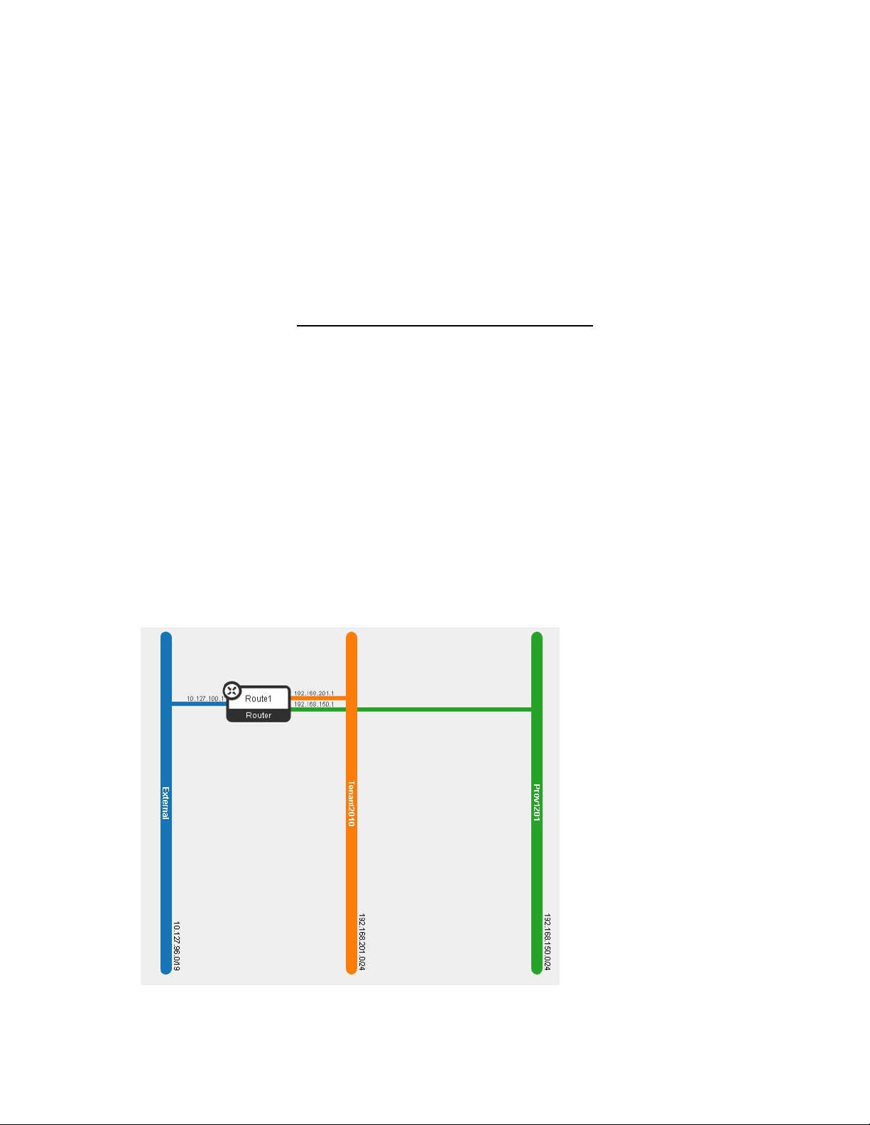
Validating CloudSystem
Use the Monitoring Dashboard to check the status of the nodes in a trio.
1. Open a browser and point to ma1, i.e. http://10.100.3.10
2. Accept the EULA and click UPDATE.
3. Log in to the CloudSystem Operations Console, default is admin with password of unset.
4. Expand the Menu drop-down then select General > Monitoring Dashboard.
5. Click the link to Launch Monitoring Dashboard. A new tab opens for HPE Helion Openstack. Login
with the admin user.
6. All services and servers displayed on the screen should be in a green status. If any are not green,
check the alarms to see if what problems need to be resolved or acknowledge. Check HPE Helion
CloudSystem 9.0 Troubleshooting Guide for reference. This guide is found on the Hewlett Packard
Enterprise website (http://www.hpe.com/info/CloudSystem/docs).
The monitoring dashboard may be disabled until the JDBC driver has been downloaded and
installed after all of the CloudSystem 9.0 appliance VMs have been brought up.
Create router
1. Launch the Horizon console.
2. Select Project > Network > Routers and then + Create Router.
3. Provide a name for the router and click Create Router.
4. Select the router name hyperlink and then the + Add Interface button. Select the appropriate tenant
subnet (repeat for additional tenant and provider subnets). Do not select the External network subnet
in this step. Click Add Interface when finished.
5. Select Project > Network > Routers, for the router you just created, select the Set Gateway button
and then select the External network. Finally, select Set Gateway to confirm selection.
6. Select Project > Network > Network Topology to view a network topology similar to the one shown
below.
Installing CloudSystem 63
Page 64

Expanding the system
Tool tips and error information are available when you hover in a text box on a screen in HP
The HP OneView InstantOn version shown in the figures in this document may be different
left navigation pane. The information that you enter on a screen is automatically saved and
Prerequisites to expanding the HC380 system
When adding an expansion system, you can use the OneView InstantOn utility to add one or more nodes
at a time, up to a 16-node configuration, and configure a computer to access the system.
Before you begin the expansion, ensure that the following prerequisites are complete:
• You have completed the preinstallation worksheet ("Preinstallation worksheets" on page 14).
• The 1Gb and 10Gb switches are configured for IPv6.
• The switches and additional appliance nodes have been racked and cabled correctly.
• If you use the VDI configuration and you purchased an expansion node with nVIDIA Tesla M60
GPUs, ensure that you have licensed and installed the nVIDIA Tesla M60 GPUs. For more
information, see "Licensing and installing nVIDIA Tesla M60 GPUs (on page 34)."
For more information, see "Configuring the system (on page 32)."
Expanding the HC380 using OneView InstantOn
IMPORTANT: If you installed CloudSystem, do not use these steps to expand your system.
Use the steps in "Expanding CloudSystem (on page 69)."
IMPORTANT:
• Verify that your management VM contains the folder
C:\ProgramData\Hewlett-Packard\StoreVirtual\InstantOn\PostDeployment. Contact
Hewlett Packard Enterprise Support if it does not.
• While HP OneView InstantOn is running, do not run anything else on the system including
running Windows Update and configuring proxies.
• Do not run HP OneView InstantOn while performing an HPE LeftHand OS upgrade.
•
OneView InstantOn. The information might take a few seconds to display.
•
from what is installed on your system. The content of the screens is the same.
• To navigate through HP OneView InstantOn, you can click Next, or click a location in the
you can go back to that screen and change or add information.
• If the system seems unresponsive, do not attempt to restart it. If processing is occurring,
1. Access the HC380 management VM on your existing cluster and click the HP OneView InstantOn
icon.
2. On the Introduction screen, accept the End User License Agreements, and then click Next.
3. On the vCenter screen, click Next.
4. On the Health screen, verify that the health is green for all system nodes and for vCenter availability.
If the health is red, possible causes are incorrect cabling, licenses not being applied, or nodes not
being fully seated. Address any issues before continuing.
The list of installed appliances appears, as well as the available appliances that can be select to
expand the cluster. Multiple appliances can be added to a single cluster simultaneously, up to a total
allow it to complete.
Expanding the system 64
Page 65
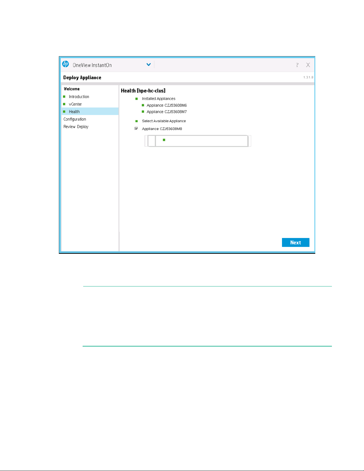
of 16 appliances in the cluster. For instance, if you already have 3 systems in your existing cluster,
If you manually configured a VLAN ID for the ESXi management network, you must remove
IP addresses for the expansion system or expansion nodes must be on the same subnet as
you can expand by adding a further 13 systems.
5. Select the systems you want to add to your existing cluster and then click Next.
6. On the IP Assignments screen, enter the appropriate information that matches your existing cluster.
For more information, see "Preinstallation worksheets (on page 14)." If you are expanding your
system by adding one node or multiple nodes, you need only enter the starting IP address. OneView
InstantOn automatically assigns the remaining, contiguous IP addresses.
NOTE:
•
it while completing the system expansion. You can add it again when the expansion is
complete.
•
the existing system.
• The Subnet and Gateway fields are automatically populated by OneView InstantOn, using
data from the initial system configuration.
Expanding the system 65
Page 66
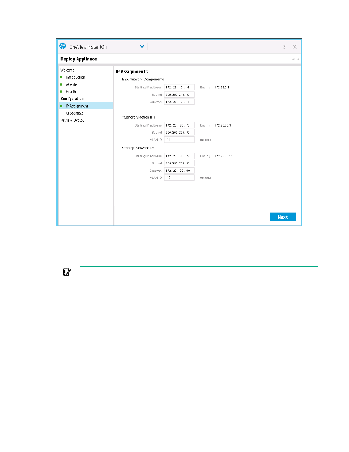
7.
Click Next.
On the Credentials screen, enter your existing StoreVirtual credentials, and then click Next.
8. On the Review Configuration screen, ensure the information that you entered is correct. If you need
to make changes, go back using the links in the left navigation pane. When you proceed, click
Deploy. Be aware that if you are deploying multiple systems, the time to complete deployment
increases.
IMPORTANT: Do not close OneView InstantOn during the deployment process. If the
deployment does not complete, see "Troubleshooting (on page 73).”
Expanding the system 66
Page 67
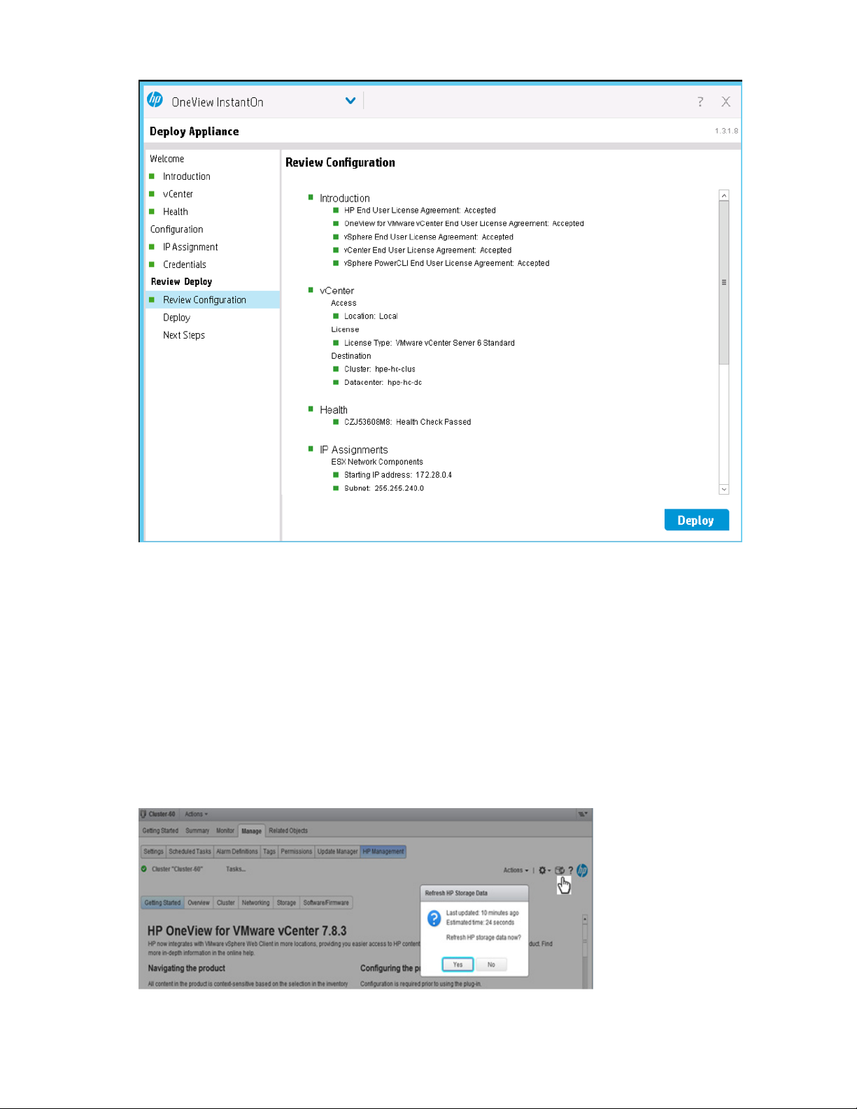
After the deployment is complete, the Next Steps screen is displayed.
9. Complete the Next Steps screen ("Completing the Next Steps screen" on page 43).
After you click Finish, you are prompted for the IP address and the user name and password for
HC380 Management UI. Following the completion of that dialog, you receive a confirmation dialog to
let you know that the cluster has been successfully expanded.
10. Before you use the storage of the expansion node or system, refresh the HPE Storage data cache.
The refresh ensures that OneView for VMware vCenter has information about the storage before
you use it.
a. Open the vCenter web client.
b. Select the cluster that was created during system deployment.
c. Select Manage > HP Management.
d. Next to the Actions menu, double-click the Refresh icon. Click Yes when prompted to refresh
data now.
Expanding the system 67
Page 68

If you need the licensing links again, restart OneView InstantOn, and the Next Steps
e.
Verify that the refresh completed by hovering over the Refresh icon to display the last time the
HPE Storage data was updated. If prompted to refresh date, select No.
NOTE:
screen automatically opens.
Expanding the system 68
Page 69

Expanding CloudSystem
Compute node expansion
When CloudSystem has been installed on an HC380, the default networking has been adjusted to suit the
CloudSystem requirements. For compute nodes, the management network, or Data Center Management
(DCM) which uses portgroup ESXcomp on the vSwitch1 standard switch in vCenter has been assigned a
VLAN ID and migrated to a vCenter distributed switch CS9_Compute_DVS and portgroup dvESXcomp
(management hosts are migrated to CS9_Mgmt_DVS and portgroup dvESXmgmt). It is the same
situation for management nodes where the DCM network which uses portgroup ESXmgmt on the
vSwitch1 standard switch in vCenter has been assigned a VLAN ID and migrated to a vCenter distributed
switch CS9_Mgmt_DVS and portgroup dvESXmgmt.
The OneView InstantOn expansion process currently does not provide an automated way to add a
compute node. Manual steps are need to configure a new node into the compute host cluster. There are
four key steps to follow, five for compute. On the details, there are specifics to either the management or
compute node that are highlighted.
1. Pre-expansion preparation of the network configuration for the new node.
2. Configure the new node in CMC.
3. Configure the volume(s) in vCenter.
4. Configure the new node on the virtual distributed switch of vCenter.
5. (Compute only) Activate the compute host cluster.
Pre-expansion preparation
1. Prepare the IP address, netmask, gateway, and VLAN’s of the new node for ESXmgmt, vMotion,
HostStorage2 and HostStorage3 networks. The values should be on the same range and values as
the existing nodes.
2. Open up the port for vmnic0 of the new node in the Top of Rack switch to access the DHCP address
via vSphere client on the Jump Station or installation laptop.
3. Launch vSphere client and connect to the new node's DHCP IP as root user.
a. Power off the HPE-HC-management VM.
b. Delete the VM from disk. There should be only the VSA VM left and keep it powered off.
c. Edit networks of the ESXi host:
i. Add the Storage VLAN to VSAeth0.
ii. Add the DCM network VLAN and configure the IP, Subnet, and Gateway of ESXmgmt.
iii. Add the vMotion VLAN and configure the IP, Subnet, and Gateway of vMotion.
iv. Add the Storage VLAN and configure the IP, Subnet, and Gateway of HostStorage2.
v. Add the Storage VLAN and configure the IP, Subnet, and Gateway of HostStorage3.
d. Remove the dash "-" at the end of the VSA VM name.
e. Verify that you can ping the ESXmgmt IP.
f. Exit the vSphere client.
4. Re-launch the vSphere client and connect to the management VM IP, i.e. 192.168.42.100.
a. Add the new ESXi node to the CloudSystem compute cluster using the ESXmgmt IP.
b. Power on the new VSA VM.
c. Once fully booted, launch the console of the VM.
i. Type start at the login prompt.
Expanding the system 69
Page 70

ii.
Go to Network TCP/IP Settings > eth0 > Provide the hostname, SN, and GW. Use the Tab
key to navigate.
iii. Log out of the session and close the console.
Configure the new node in the CMC
1. Launch CMC and login as the admin user.
a. On the Toolbar, select Find > Find Systems… > Add.
b. Enter the VSA IP address you configured on step 4c on the pre-expansion.
The new node will show up on the Available Systems.
2. Click Log in to view.
3. Right click on the new node and select Add to Existing Management Group …
4. Confirm the Group Name and click Add. It may take a minute to finish.
5. After the new node shows up on the management group, right click and select Add to Existing
Cluster…
6. Confirm the Cluster name and click OK. Click OK again on the WARNING pop-up message.
The new node will show up on the Storage Systems group.
7. Go back to vCenter and get the iSCSI name of the new node using either of the following steps:
o Select the server and go to Configuration > Hardware > Storage Adapters > select the iSCSI
Software Adapter > under Details is the iSCSI name.
o Click Properties… hyperlink under Details then click Configure… to copy the iSCSI Name.
8. Go back to the CMC and add the server.
9. Right click on Servers and select New Server…
10. In the New Server dialog, perform the following steps:
a. Use the ESXmgmt IP of the new node for the Name and CHAP Name
b. Keep the two iSCSI security checkboxes enabled (default)
c. For the CHAP passwords, ensure that Target and Initiator are 12 characters long and are unique.
11. Present the volume(s) to the newly added server by right-clicking on the newly added server and
selecting Assign and Unassign Volumes and Snapshots…
12. Assign the volumes by performing the following steps:
a. For the new compute host, select only the VSA management volume.
b. For the new management host, select both CS9 and VSA management volumes.
13. Get the iSCSI name of the volume to be configured on vCenter.
a. Select the volume.
b. On the Details tab under Target Information, copy the value for the iSCSI Name field on the
Target Information. This is the iSCSI server IQN you will use later in vCenter.
Configure the volume in vCenter
1. Configure the presented volume(s) on vCenter.
a. Select the new node, go to Configuration > Hardware > Storage Adapters > select the iSCSI
Software Adapter > Details > Properties…
b. On the General tab, select CHAP…
i. Select Use CHAP on both options
ii. Use the same name configured on the CMC (step 10a above of the CMC setup section)
iii. Use the same Target and Initiator passwords
Expanding the system 70
Page 71

2.
On the Dynamic Discovery tab
a. Select Add…
b. Provide the iSCSI Server IP. You can obtain this IP in two ways.
— From the other nodes configured on vCenter
— From the CMC, navigate to the VSA cluster then go to the iSCSI tab. The iSCSI Server IP is
the value of the Virtual IP.
c. Click CHAP… and verify that both Inherit from Parent checkboxes are selected.
3. The Static Discovery tab should be automatically updated. If not, perform these steps:
a. Select Add…
b. Provide the iSCSI Server IP similar to the Dynamic Discovery.
c. Provide on the iSCSI Target Name the IQN you obtained earlier on step 13 above of the CMC
setup section.
d. Click CHAP… and verify that both Inherit from Parent checkboxes are selected.
e. After closing the Properties dialog, perform a Rescan.
The iSCSI device is displayed on the Details dialog.
f. Go to the storage and verify that the datastore also shows up on the newly added node.
Configure the VDS of vCenter
1. Use the following steps to configure the new Compute node to the virtual distributed switches:
a. Using the vSphere Client, go to Inventory > Networking.
b. Right click on CS9_Compute_DVS and click Add Host…
i. Select the new node.
ii. Select physical adapters vmnic6 and vmnic7.
iii. Set the destination port group of vmk3 to dvESXcomp.
iv. Click Next on the Virtual Machine Networking.
v. Click Finish.
c. Right click on Comp-CloudData-Trunk and click Add Host…
i. Select the new node.
ii. Select the physical adapters vmnic8 and vmnic9.
iii. Click Next on Network Connectivity.
iv. Click Next on Virtual Machine Networking.
v. Click Finish.
2. Use the following steps to configure the new Management node to the virtual distributed switches:
a. Using the vSphere Client, go to Inventory > Networking.
b. Right click on CS9_Mgmt_DVS and click Add Host…
i. Select the new node.
ii. Select physical adapters vmnic6 and vmnic7.
iii. Set the destination port group of vmk3 to dvESXmgmt.
iv. Click Next on the Virtual Machine Networking.
v. Click Finish.
c. Right hpcs-dataXXXXXX distributed vswitch and click Add Host…
i. Select the new node.
ii. Select the physical adapters vmnic8 and vmnic9.
Expanding the system 71
Page 72

iii.
Click Next on Network Connectivity.
iv. Click Next on Virtual Machine Networking.
v. Click Finish.
d. Right hpcs-storageXXXXXX distributed vswitch and click Add Host…
i. Select the new node.
ii. Click Yes to the Warning pop-up (since no physical adapter was selected).
iii. Click Next on Network Connectivity.
iv. Click Next on Virtual Machine Networking.
v. Click Finish.
e. Enable HA and DRS on the management cluster.
Activate the compute host cluster
When activating the compute cluster in CS9, there are two scenarios to consider.
Scenario 1: The new host is on the same CS9 compute cluster as the existing hosts. In this scenario,
the new host needs to join the existing cluster.
1. All deployed instances need to be terminated or migrated first.
2. From the CloudSystem Ops Console, deactivate the compute cluster.
3. Activate the same compute cluster with the new host included.
4. Re-deploy the terminated instances or migrate them back to the newly activate compute cluster.
Scenario 2: The new host is on a different CS9 compute cluster. The steps configured earlier for the
new compute host has it configured on the same cluster as existing ones.
1. Create a new compute cluster.
2. Configure the CS9 virtual distributed switches on the new cluster.
3. Migrate the new compute host into the new cluster.
4. From the CloudSystem Ops Console, verify that the new cluster got discovered.
5. Activate the new compute cluster with the new host.
Expanding the system 72
Page 73

Troubleshooting
Troubleshooting OneView InstantOn
Certificate error when launching vCenter web client
Symptom
When launching the vCenter web client on the Next Steps screen of the OneView InstantOn wizard, a
certificate error is displayed when you attempt to log in.
Action
You can still log in and use the vCenter web client. The certificate error will not affect use of the system.
To resolve the certificate error:
1. After logging in, go to the Home tab of the vCenter web client and select HP Management
Administration.
2. On the OneView for vCenter window, select Install a signed certificate.
3. Follow the steps on the Certificate Management window that displays. You can choose to install a
self-signed certificate or a certificate signed by a trusted authority.
HC380 nodes are not discovered
Symptom
OneView InstantOn is not able to discover the HC380 nodes.
Cause
IPv6 may not be enabled for the 1Gb or 10Gb switches.
Action
Enable IPv6 for the 1Gb or 10Gb switches. For more information, see "IPv6 enablement at switch level
(on page 8)."
OneView InstantOn hangs during deployment
Symptom
While configuring the system using OneView InstantOn, the deployment process hangs or does not
complete.
Action
Perform one or more of the following actions.
• Verify that your firewall is configured correctly.
• Ensure that the VLAN tags are configured correctly.
• Ping the affected IPv4 addresses to investigate cause.
• Ensure that the switches are configured correctly.
• If the connection to a node does not open, troubleshoot that specific node.
Troubleshooting 73
Page 74

• If there are IP address conflicts, ensure that the IP addresses that are validated on the IP
Assignment screen are not in use.
• If you are unable to resolve the issue or you discover another issue, contact Hewlett Packard
Enterprise Support.
vCenter license status on Health screen is red
Symptom
OneView InstantOn does not proceed with deployment because the vCenter license status on the Health
screen is red.
Action
Perform the following steps:
1. Apply a valid vCenter and vSphere license in vCenter.
2. Close and restart vCenter.
OneView InstantOn detects the new license and allows deployment.
OneView InstantOn progress indicator appears to hang
Symptom
During installation, the progress indicator (countdown timer) in OneView InstantOn might appear to hang
at various times.
Action
No action is required. Do not cancel or stop the deployment.
The system configuration is continuing although the indicator might not update. The countdown timer will
resume shortly.
"Invalid username and password" error appears when you specify a local vCenter
Symptom
When you select a local vCenter, the default credentials for VMware vCenter are automatically populated
in the Username and Password fields. At times, the following error message appears: Invalid Username
and Password
Action
This issue occurs intermittently. Perform one or both of the following actions:
• Reenter your username and password.
• If the issue persists, reboot the Management VM.
Application performance on management VM might decrease
Symptom
Application performance on the Management VM might decrease when OneView InstantOn is performing
a system health check.
Action
Wait for the OneView InstantOn health check to complete.
Troubleshooting 74
Page 75

"The page cannot be displayed" error message appears
Symptom
When attempting to access the Online Help or the Software Depot link under Upgrades, the following
error message appears: The page cannot be displayed.
Action
Configure the proxy server for Internet Explorer on the Management VM.
OneView InstantOn hangs with error message "0:02 Adding SAN to vCenter"
Symptom
OneView InstantOn hangs during the last two seconds of the deployment process with the following
message: 0:02 Adding SAN to vCenter.
Cause
This issue usually occurs when you specify a remote vCenter installation. One possible cause is that the
default vCenter user, [email protected], does not have full access to OneView for vCenter and
to the Storage Administration Portal. If it does not have access to both applications, the error message
appears.
Action
Ensure that the user [email protected] has full access to OneView for vCenter and the
Storage Administrator Portal.
vSphere HA errors
Perform the following steps to overcome any issues that are occurring with the vSphere cluster High
Availability configuration.
1. Using the management VM, launch vSphere Client and login to the cluster using the following
credentials:
o Hostname: localhost
o User: [email protected]
o Password: HyperConv!234
You may see some alarms against the cluster name, hosts and possibly VMs. These are informing of
problems with the configuration of High Availability in the new cluster.
You may also see errors in the Recent Tasks window, one of which is reporting an error when
migrating the Management VM to shared storage.
2. Resolve the issues by disabling and enabling vSphere HA:
a. Right click on the cluster name in the left pane of the client, select Edit Settings….
b. Uncheck the Turn On vSphere HA item.
c. Click OK.
d. The alarms should clear and migration of the Management VM migration will begin - see its
progress in the Recent Tasks window.
e. When the VM migration is complete, right-click the cluster name and select Edit Settings… again.
f. Check the Turn On vSphere HA item.
g. Click OK.
Troubleshooting 75
Page 76

Troubleshooting CloudSystem
Connection error to vCenter server
Symptom
The following error message appears during installation:
Could not connect to vCenter server at …
Initialization failed…cannot proceed.
Action
Perform one or both of the following actions:
• Verify that the server and username values are correct.
• Verify that the vCenter server service is running.
Installation utility cannot assign the DCM network VLAN to the ESXmgmt portgroup
Symptom
Unable to tag the DCM network VLAN to the ESXmgmt portgroups.
Cause
The installation utility is trying to assign the DCM network VLAN to the ESXmgmt portgroup on the
standard switch on each of the ESXi hosts. If the DCM VLAN is not configured through the TORs, then
loss of connectivity may keep this task from completing properly.
Action
1. Obtain the DCM VLAN.
This information was obtained for the CloudSystem preinstallation worksheet ("CloudSystem" on
page 18).
2. Make sure that the DCM VLAN is enabled in the TOR switches.
3. Execute the following steps on the OneView InstantOn management VM.
a. If not already done, configure a laptop or workstation to access the management VM
("Configuring a laptop or workstation to access the system" on page 33).
b. Migrate the management VM to node 1 if it is not already there.
This migration should have been performed automatically by OneView InstantOn after the Next
Steps page appears.
c. Migrate the management VM disk away from the VSA SAN storage to a local datastore (for
example, datastore1).
If this migration is not done, connectivity problems might occur and the management VM will stop
functioning properly.
d. Connect to each host (except the management VM) directly with vSphere client and set
ESXmgmt portgroup to have VLAN x:
esxcli network vswitch standard portgroup set -p ESXmgmt --vlan-id
<DCMVLAN>
e. On the management VM (include both commands on the same line, separated by ';')
esxcli network vswitch standard portgroup set -p ESXmgmt --vlan-id
<DCMVLAN> ; esxcli network vswitch standard portgroup set -p mgmtVMNetwork
--vlan-id <DCMVLAN>
Troubleshooting 76
Page 77

If you lose connection to the networks, you may have to use iLO to restore connectivity.
Unable to migrate host to management cluster
Symptom
The installation utility created the CS9Mgmt cluster in vCenter but is unable to migrate one of the ESXi
nodes from the default cluster to the new management cluster.
Cause
The installation utility is trying to create the CS9Mgmt cluster in vCenter and then migrate one of the ESXi
nodes from the default OneView InstantOn cluster to this new CloudSystem management cluster.
Because the installation utility runs on the management VM, the VM cannot be turned off and put into
maintenance mode for moving the host to the management cluster.
Action
If the utility encounters problems while attempting to move the host to the management cluster, you must
perform the following steps:
1. Create a cluster (CS9Compute).
2. Disable HA on the original cluster.
3. For all hosts (except ESXi host that is the management VM), perform the following steps:
a. Shut down the guest OS for the VSA VM and wait about a minute.
You may have to use the StoreVirtual CLI commands (for example, cliq getVolumeInfo) to
assess the status of volumes before this step can complete.
b. Move the host to maintenance mode.
c. Migrate the host to the new CS9Compute cluster.
d. Move the host out of maintenance mode.
e. Power on VSA VM.
4. Enable HA on CS9Compute if there is more than one node.
5. Enable DRS on CS9Compute node.
Both the management and compute clusters must have DRS enabled. If the compute cluster no
longer satisfies the minimum requirements for HA, it is disabled.
Trouble setting up storage
Symptom
Connectivity issues may occur when the installation utility attempts to allocate disk space from the VSA
cluster and make it shared between all ESXi hosts.
Explanation
The Installer is trying to allocate as close to 8TB of disk space as possible from the VSA cluster and make
it shared between all ESXi hosts. If the credentials are no longer viable, there may be connectivity issues.
After creating a volume in VSA, then an attempt is made to register the volume with the ESXi hosts. The
volume is assumed to be created with RAID-10.
Action
Use OneView for vCenter to allocate a datastore, or use the following steps to create it manually:
1. Launch the StoreVirtual Centralized Management Console.
2. Log in to the VSA Cluster (as specified in OneView InstantOn, default is HP-HyperConv-XXX).
Credentials were supplied during the OneView InstantOn setup.
3. Create a CS9MgmtDatastore volume with as close to 8TB of space (RAID-10) as possible.
Troubleshooting 77
Page 78

4.
Share the volume with all servers.
5. Launch vSphere and connect to the vCenter server.
6. Pick the CS9 management host and click Rescan All, then Add Storage (CS9MgmtDatastore).
7. On the remaining hosts in compute clusters, either click Rescan All, or wait for the datastore to be
visible.
If the factory datastores [remote-install-location] still exist, remove them from each ESXi host. If the
factory datastores exist when CloudSystem tries to activate compute nodes, the activation fails.
Distributed switches were not created as expected
Symptom
Distributed switches were not created.
Explanation
On the CS9 management hosts, the CS9_Mgmt_DVS distributed switch is created with two uplink ports
and attached to vmnic6 and vmnic7. Two portgroups, dvESXmgmt and dvmgmtVMNetwork, are created
on the switch with the DCM VLAN. The ESXmgmt portgroup on the standard switch vSwitch1 is migrated
to the dvESXmgmt portgroup.
On the compute hosts, the CS9_Compute_DVS switch is created with the dvESXcomp portgroup with two
uplinks and attached to vmnic6 or vmnic7. The ESXmgmt portgroup on standard vSwitch1 is migrated to
this dvESXcomp portgroup. The Comp-CloudData-Trunk distributed switch is created with two uplinks on
vmnic8 or vmnic9. No portgroups are created on the Comp-CloudData-Trunk at this time.
Action
Migrate ESXmgmt on vSwitch0 to CS9_Mgmt_DVS using the following steps.
1. Create CS9_Mgmt_DVS w/ dvESXMgmt portgroup (VLAN <DCM>).
2. Navigate to Inventory -> Networking, right-click on CS9_Mgmt_DVS, and select Manage Hosts.
3. Pick all hosts in the management cluster (for a two-node solution, there is a single management
node).
4. Select vmnic6 or vmnic7 for these hosts.
5. Assign DV destinations for the ESXmgmt standard portgroup to the corresponding dvESXmgmt
distributed port group on each respective host. Do not change the other port groups.
Distributed Compute Switches
Migrate ESXmgmt on vSwitch0 to CS9_Compute_DVS using the following steps.
1. Create CS9_Compute_DVS with dvESXcomp portgroup (VLAN <DCM>).
2. Right-click CS9_Comp_DVS, manage hosts.
3. Pick all hosts in compute cluster and verify vmnic6 or vmnic7 selected for these hosts.
4. Assign dv destinations for the ESXmgmt standard portgroup to the corresponding dvESXComp
distributed portgroup on each host.
5. Create Comp-CloudData-Trunk on vmnic8 or vmnic9 for all compute hosts (no portgroups).
Foundation or Enterprise zip files on the datastore supplied by the factory image are not found
Symptom
When you attempt to upload OVA images, the Foundation or Enterprise zip files on the datastore supplied
by the factory image are not found.
Action
Troubleshooting 78
Page 79

1.
On the ESXi server that is the management VM, browse to the datastore1 datastore.
2. Locate the cloud folder and download the Enterprise and Foundation zip files to a temporary location
on the management appliance.
3. Unzip the Enterprise and Foundation zip files.
4. Use vSphere to upload the cs*.ova files (cs-mgmt, cs-cloud, cs-sdn, cs-monitoring, cs-update,
cs-enterprise, cs-ovsvapp).
Foundation or Enterprise zip files can not be unzipped
Symptom
When you attempt to upload OVA images, the Foundation or Enterprise zip files can not be unzipped.
Action
1. On the ESXi server that is the management VM, browse to the datastore1 datastore.
2. Locate the cloud folder and download the Enterprise and Foundation zip files to a temporary location
on the management appliance.
3. Unzip the Enterprise and Foundation zip files.
4. Use vSphere to upload the cs*.ova files (cs-mgmt, cs-cloud, cs-sdn, cs-monitoring, cs-update,
cs-enterprise, cs-ovsvapp).
Storage is not available for OVA images
Symptom
When you attempt to upload OVA images, storage is not available.
Action
1. On the ESXi server that is the management VM, browse to the datastore1 datastore.
2. Locate the cloud folder and download the Enterprise and Foundation zip files to a temporary location
on the management appliance.
3. Unzip the Enterprise and Foundation zip files.
4. Use vSphere to upload the cs*.ova files (cs-mgmt, cs-cloud, cs-sdn, cs-monitoring, cs-update,
cs-enterprise, cs-ovsvapp).
Issues creating first management appliance
Symptom
The installation utility is unsuccessful at creating the first management appliance.
Explanation
This issue can occur if the installation utility is not able to create the deployer.conf file that is used by
csstart.exe.
Action
1. Navigate to the %CS9INSTALL%\Foundation folder.
2. Locate the csstart.exe file.
3. Edit the deployer.conf file to match the configuration.
4. Launch csstart.exe start --eula-accepted
After about 10 minutes the first management appliance is available.
5. Reset the EULA so that on first login you are prompted to accept the license.
Troubleshooting 79
Page 80

CloudSystem was not deployed successfully
Symptom
CloudSystem was not deployed successfully.
Action
See the HPE Helion CloudSystem 9.0 Troubleshooting Guide on the Hewlett Packard Enterprise website
(http://www.hpe.com/info/CloudSystem/docs).
Could not update the hpcs-data* distributed switch
Symptom
The hpcs-data* distributed switch could not be updated during the installation.
Cause
After CloudSystem is deployed, the installer tries to increase the number of uplinks to two on the
hpcs-data* distributed switch for each ESXi compute host.
Action
1. Make sure that hpcs-data* has two uplinks assigned for each management host.
2. Assign vmnic8 or vmnic9 for each management host.
3. Set the portgroup to have a route based on IP hash and both uplinks in active mode.
Could not register vCenter with CloudSystem
Symptom
The installation process could not register vCenter with CloudSystem.
Cause
The installer is trying to register vCenter with the CloudSystem to allow for compute nodes to be activated.
Action
Perform one or both of the following actions:
• Verify that vCenter is accessible.
• Use the following steps to register vCenter with CloudSystem.
a. Launch the CloudSystem 9 Operations console.
b. Select Menu > System > Integrated Tools.
c. Select Register vCenter.
d. Provide the smgmt01 values. The default values are listed, but your values may vary:
— vCenter Name: smgmt01
— vCenter Details: 172.28.10.10
— vCenter Administrator: [email protected]
— vCenter Password: Password!234
e. Click Register.
The vCenter count increases, the CS9 busy graphic ends, and the notification count increases.
f. Expand the notifications (the bell icon near the top right of the browser window) to view a
notification that indicates that the vCenter was registered successfully.
Troubleshooting 80
Page 81

Could not activate compute nodes
Symptom
Could not activate compute nodes.
Explanation
The installer is trying to add any hosts in the compute cluster as activated nodes in CloudSystem.
Potential problems could occur if vCenter is not registered or it fails to find an OVA image.
Action
Perform one or both of the following actions:
• Follow the steps below to activate the compute nodes.
• Refer to HPE Helion CloudSystem 9.0 Administrator Guide located on the Hewlett Packard
Enterprise website (http://www.hpe.com/info/CloudSystem/docs).
1. Launch vSphere, and verify the following:
o that each compute host is alive and not in maintenance mode.
o that the Comp-CloudData-Trunk distributed switch has been created and uplinks assigned for
each compute host.
2. In the CS9 Operations Console, select Menu > Compute > Compute Nodes.
3. For each compute cluster, perform the following:
a. Select a cluster (e.g. sHosts01) by clicking on the circled checkmark next to the cluster name.
b. Click the Activate button.
c. Select Distributed vSwitch Name option and supply the value Comp-CloudData-Trunk.
d. Select the Queue for Activation button.
e. Select Complete Activations.
f. Click Confirm Activations.
An ovsvapp-<compute_host> VM instance is created for each compute host. This step can take
several minutes and will depend on the number of compute nodes.
If the activation fails, use the following troubleshooting options:
— Sometimes the activation has completed but may show a RED status. Try refreshing the
browser and observe whether it changes to GREEN.
— Verify that enough DCM IP addresses are allocated.
— If any of the compute hosts are in maintenance mode or the management appliance (ma1)
cannot maintain a network connection to a compute host, the ovsvapp deploy will fail.
— Use the Menu General Logging Dashboard to help diagnose any problems.
— View additional information in the white paper entitled "HPE Helion CloudSystem 9.0
networking configuration and troubleshooting" found on the Hewlett Packard Enterprise
website (http://www.hpe.com/info/CloudSystem/docs).
Could not create Tenant VLAN Segment Ranges
Symptom
Could not create tenant VLAN segment ranges.
Explanation
The installer is attempting to create segment ranges in CloudSystem for VLANs listed in the Tenant VLAN
section of the user interface. Potential problems could occur if the OpenStack services are not all running.
Troubleshooting 81
Page 82

Action
Running deploy a second time from the UI will usually fix most problems. For more information, see
"Tenant and provider networking (on page 61)."
Could not create Tenant and Provider VLAN Networks
Symptom
Could not create Tenant and Provider VLAN Networks.
Explanation
The installer is creating the Tenant and Provider VLAN networks specified in the UI. Potential problems
could be that Tenant segment ranges were not created or all OpenStack services are not running. Other
setup problems could occur if the VLAN is not valid.
Action
Re-run the CloudSystem installation utility or refer to "Tenant and provider networking (on page 61)."
Could not add Subnets to Networks
Symptom
Could not add subnets to networks.
Explanation
The installer is attempting to create a subnet for a given VLAN from the CIDR specified in the user
interface. Potential causes could be that the VLAN does not exist or the CIDR overlaps with another
network.
Action
For more information, see "Tenant and provider networking (on page 61)."
Could not create router
Symptom
Could not create router.
Explanation
The installer is attempting to create a router in CloudSystem based on any Tenant, Provider, and External
networks specified in the user interface. It will only run once, so any new networks or changes will have to
be manually updated.
Action
For more information, see "Create router (on page 63)."
Could not update to 9.02
Symptom
Could not update to CloudSystem 9.02.
Action
Perform one or both of the following actions.
• Run the program.
Troubleshooting 82
Page 83

• Perform a manual update by referring to HPE Helion CloudSystem 9.0 Installation Guide located on
the Hewlett Packard Enterprise website (http://www.hpe.com/info/CloudSystem/docs).
Could not update passwords
Symptom
Could not update the administrator password for CloudSystem.
Action
Hewlett Packard Enterprise recommends that you back up your system and take a snapshot of
CloudSystem before changing. If the process fails, see HPE Helion CloudSystem 9.0 Administrator Guide
for the manual update process or to restore to a previous snapshot. The guide is located on the Hewlett
Packard Enterprise website (http://www.hpe.com/info/CloudSystem/docs).
VSA volumes did not stabilize in 10 minutes…cannot continue
Symptom
VSA VM cannot be powered off.
Explanation
Before creating the CS9 Management cluster and moving the management VM to this cluster, the utility
powers off the VSA VM on the management node. If the VSA volumes are pending activity, the VM cannot
be powered off until the VSA storage reaches a stable state.
Action
For more information, see "Trouble migrating host to management cluster."
VM <name> did not power off - <error msg>
Symptom
VSA VM could not be powered off on the management node.
Explanation
Before creating the CS9 Management cluster and moving the management VM to this cluster, the VSA
VM must be powered off on the management node. If the VSA volume could not be powered off, then the
VSA volume has some pending activity.
Action
The VM will have to be powered off manually. For more information, see "Trouble migrating host to
management cluster."
Problem finding original vCenter cluster
Symptom
Installation utility is not able to locate original cluster name.
Explanation
When trying to create the CS9Compute cluster and migrate all future compute nodes to this cluster, if the
installation utility cannot find the original cluster name as specified during the OneView InstantOn
deployment, it cannot proceed.
Action
Troubleshooting 83
Page 84

Ensure that the original cluster name (e.g. HC-CLUS) that was specified during the OneView InstantOn
deployment is in place, including the ESXi hosts in that cluster.
Could not find the VSA VM on host <name>
Symptom
The installation utility cannot locate the VSA VM on the specified host.
Explanation
When trying to migrate ESXi hosts to the new compute cluster, the utility must be able to shut down the
VSA VM on each respective host. If the utility is not able to locate it (if the name does not match the
“SVVSA-*” pattern, for instance), the system cannot shut it down and allow the respective host to enter
maintenance mode prior to migrating the host to the new cluster.
Action
Ensure that the utility can locate the VSA VM on each respective host.
Deploy CloudSystem
1. Ensure that the management appliance is active.
2. Ensure that you have downloaded the MySQL JDBC library file (libmysql-java_5.1.32-1_all.deb).
3. Deploy the .deb file on the management appliance.
4. Log into the management appliance and launch csdeploy.
Troubleshooting 84
Page 85

Appendix A: Network switch configuration
Switch
Port
Device
Port
Comment
FP+ - 1
1
HC380 Node 1
FlexibleLOM1
FP+ - 2
1
HC380 Node 1
FlexibleLOM2
FP+ - 1
2
HC380 Node 2
FlexibleLOM1
FP+ - 2
2
HC380 Node 2
FlexibleLOM2
FP+ -1
3
HC380 Node 3
FlexibleLOM1
FP+ -2
3
HC380 Node 3
FlexibleLOM2
FP+ -1
51
HPE
51
IRF Link
FP+ -1
52
HPE
52
IRF Link
HC380 node 1 iLO
Hewlett Packard Enterprise switches
This section describes how to configure a 3-node HC380 appliance with a pair of HPE
Network cabling
5900A-48XG-4QSFP+ switches.
The following table shows an example 10GbE networking connectivity to two HPE
5900AF-48XG-4QSFP+ switches configured with HPE Intelligent Resilient Framework (IRF)+.
HPE
5900AF-48XG-4QS
HPE
5900AF-48XG-4QS
HPE
5900AF-48XG-4QS
HPE
5900AF-48XG-4QS
HPE
5900AF-48XG-4QS
HPE
5900AF-48XG-4QS
HPE
5900AF-48XG-4QS
HPE
5900AF-48XG-4QS
5900AF-48XG-4QS
FP+ -2
5900AF-48XG-4QS
FP+ -2
In addition to the 10GbE connectivity needs, the HPE Integrated Lights Out connection on each DL also
needs to be connected and configured on the same management network as the 10GbE Ports on the
DLs. There are several ways to do this, for example connecting the 1GbE connections to an existing
1GbE switch that is on the same Layer 2 management network (VLAN) as the 10GbE components. You
could also insert an X120 1G SFP RJ45 Transceiver (JD089B) in to the HPE 5900AF-48XG-4QSFP+
switch and use ports on the switches for the iLOs as well.
The following table shows the 1GbE RJ45 connections required for a three-node 10GbE based HC380
solution.
Device Port
Appendix A: Network switch configuration 85
Page 86

iLO
HC380 Node 2
iLO
HC380 Node 3
iLO
Device Port Comment
HC380 Node 1
Configuring the switches
The following procedures describe an example of how to configure the two HPE 5900AF-48XG-4QSFP+
switches for use in an HC380 for the general virtualization configuration. Although two 10GbE based
switches are used here in this example, the same steps can be leveraged for a 1GbE based HC380
solution using an HPE 5900AF-48G-4XG-2QSFP+ switch, taking into account the additional 1GbE
connections that are required. For more information about the connectivity requirements, see
"Configuring the network switches (on page 32)."
The example below assumes you already have a 1GbE infrastructure where the iLO from each HC380
node is connected. This 1GbE infrastructure must be able to communicate to the HPE
5900AF-48XG-4QSFP+ switches referenced in this section. Hewlett Packard Enterprise requires that all
connections from the HC380 (iLO, 10GbE, or 1GbE) be connected to the same layer 2 and layer 3
networks.
Connecting to the serial console port
For each switch in the configuration, initial setup will be done over the serial port. This section shows how
to connect to the serial port.
This task requires a part number 5185-8627 RJ45-DB9 console cable to connect the serial port and a
serial terminal or serial terminal emulator (Laptop for example) with an available serial port (DB9)
connector.
1. Connect a serial terminal or laptop or server running a terminal emulator to the serial port of the HPE
5900AF-48XG-4QSP+ switch. The Serial port is located on the back (power side) of the switch.
2. On the laptop or server, open up a terminal emulation program (i.e. Tera Term) and select the serial
connection option with the serial port configuration.
Bits per second: 9600
Data bits: 8
Parity: None
Stop bits: 1
Flow control: None
Emulation: VT100
3. Press OK to open the connection.
IRF configuration
To set up the initial configuration for the HPE 5900AF-48XG-4QSFP+ Switch 1 via the serial port,
complete the following steps:
1. Configure the switch.
On initial boot and connection to the serial or console port of the switch, the Comware setup should
automatically start and attempt to enter Automatic configuration.
Automatic configuration attempt: 1.
Interface used: M-GigabitEthernet0/0/0.
Enable DHCP client on M-GigabitEthernet0/0/0.
Automatic configuration is running, press CTRL_C or CTRL_D to break.
Appendix A: Network switch configuration 86
Page 87

2.
Press ctrl and c or ctrl and d to stop the automatic configurations.
Whenever the instructions call for network configuration in "system view" context, if at the <HPE>
prompt, issue the system-view command to get to the [HPE] prompt.
Automatic configuration is aborted.
Line aux0 is available.Press ENTER to get started.<HPE> system-view
System View: return to User View with Ctrl+Z.
3. Configure the IRF ports.
[HPE] interface range FortyGigE 1/0/51 to FortyGigE 1/0/52
[HPE-if-range] shutdown
[HPE-if-range] quit
[HPE] irf-port 1/1
[HPE-irf-port1/1] port group interface FortyGigE 1/0/51
[HPE-irf-port1/1] port group interface FortyGigE 1/0/52
[HPE-irf-port1/1] quit
[HPE]save
The current configuration will be written to the device. Are you sure? [Y/N]:y
Please input the file name(*.cfg)[flash:/startup.cfg]
(To leave the existing filename unchanged, press the enter key):
HPE 5900AF-48XG-4QSFP+ Switch 1
To set up the initial configuration for the HPE 5900AF-48XG-4QSFP+ Switch 1 via the serial port,
complete the following steps:
1. Configure the switch.
On initial boot and connection to the serial or console port of the switch, the Comware setup should
automatically start and attempt to enter Automatic configuration.
Automatic configuration attempt: 1.
Interface used: M-GigabitEthernet0/0/0.
Enable DHCP client on M-GigabitEthernet0/0/0.
Automatic configuration is running, press CTRL_C or CTRL_D to break.
2. Press ctrl and c or ctrl and d to stop the automatic configurations.
Whenever the instructions call for network configuration in "system view" context, if at the <HPE>
prompt, issue the system-view command to get to the [HPE] prompt.
Automatic configuration is aborted.
Line aux0 is available.Press ENTER to get started.<HPE> system-view
System View: return to User View with Ctrl+Z.
3. Configure the IRF ports.
[HPE] interface range FortyGigE 1/0/51 to FortyGigE 1/0/52
[HPE-if-range] shutdown
[HPE-if-range] quit
[HPE] irf-port 1/1
[HPE-irf-port1/1] port group interface FortyGigE 1/0/51
[HPE-irf-port1/1] port group interface FortyGigE 1/0/52
[HPE-irf-port1/1] quit
[HPE]save
The current configuration will be written to the device. Are you sure? [Y/N]:y
Please input the file name(*.cfg)[flash:/startup.cfg]
(To leave the existing filename unchanged, press the enter key):
Appendix A: Network switch configuration 87
Page 88

HPE 5900AF-48XG-4QSFP+ Switch 2
To set up the initial configuration for the HPE 5900AF-48XG-4QSFP+ Switch 2 via the serial port,
complete the following steps:
1. Configure the switch.
On initial boot and connection to the serial or console port of the switch, the Comware setup should
automatically start and attempt to enter Automatic configuration.
Automatic configuration attempt: 1.
Interface used: M-GigabitEthernet0/0/0.
Enable DHCP client on M-GigabitEthernet0/0/0.
Automatic configuration is running, press CTRL_C or CTRL_D to break.
2. Press ctrl and c or ctrl and d to stop the automatic configurations.
Whenever the instructions call for network configuration in "system view" context, if at the <HPE>
prompt, issue the system-view command to get to the [HPE] prompt.
Automatic configuration is aborted.
Line aux0 is available.Press ENTER to get started.<HPE> system-view
System View: return to User View with Ctrl+Z.
3. Change the IRF member ID and reboot the switch.
[HPE] irf member 1 renumber 2
Renumbering the member ID may result in configuration change or loss.
Continue?[Y/N] Y
[HPE] save
The current configuration will be written to the device. Are you sure? [Y/N]:y
Please input the file name(*.cfg)[flash:/startup.cfg]
(To leave the existing filename unchanged, press the enter key):
Validating file. Please wait...
Saved the current configuration to mainboard device successfully.
[HPE] quit
<HP> reboot
Start to check configuration with next startup configuration file, please
wait.........DONE!This command will reboot the device. Continue? [Y/N]:yNow
rebooting, please wait...
4. Still connected to switch 2 via the serial port, once the switch reboot is complete, configure the IRF
ports.
<HPE> system-view
[HPE] interface range FortyGigE 2/0/51 FortyGigE 2/0/52
[HPE-if-range] shutdown
[HPE-if-range] quit
[HPE] irf-port 2/2
[HPE-irf-port2/2] port group interface FortyGigE 2/0/51
[HPE-irf-port2/2] port group interface FortyGigE 2/0/52
[HPE-irf-port2/2] quit
[HPE] irf-port-configuration active
[HPE] interface range FortyGigE 2/0/51 FortyGigE 2/0/52
[HPE-if-range] undo shutdown
[HPE-if-range] quit
[HPE] save
The current configuration will be written to the device. Are you sure? [Y/N]:y
Please input the file name(*.cfg)[flash:/startup.cfg]
(To leave the existing filename unchanged, press the enter key):
Validating file. Please wait...
Appendix A: Network switch configuration 88
Page 89

Saved the current configuration to mainboard device successfully.
Configure IRF priority
Configure the domain and IRF parameters. The <<net_switch_domain_id>> value is an arbitrary number,
but must be unique from other IRF domains. Switch prompts will not be displayed in the remaining switch
configuration information in this section of the documentation.
From system-view, run the following commands.
system-view
irf domain <<net_switch_domain_id>>
irf member 1 priority 32
irf member 2 priority 30
irf mac-address persistent always
Configure Multi-Active Detection (MAD) and Remote access to the switch
Hewlett Packard Enterprise recommends that you implement a multi-active detection (MAD) mechanism
to detect the presence of multiple identical IRF fabrics, handle collisions, and recover from faults in the
unlikely event of an IRF split or failure. For more information, see HPE 5920 & 5900 Switch Series IRF
Configuration Guide. Configuration of MAD is not covered in this document.
Configure the VLANs
To create the necessary VLANs, complete the following step on both switches.
From system-view, run the following commands.
vlan <<mgmt_net_vlan>>
name MGMT-VLAN
quit
vlan <<vmotion_net_vlan>>
name vMotion-VLAN
quit
vlan <<iscsi_net_vlan>>
name iSCSI-VLAN
quit
vlan <<vm_production_net_1_vlan>>
name VM-Production-VLAN1
quit
save
Configure IP addresses
There are several ways, both inband and out of band, to assign an IP address to the IRF switch pair to
manage it. The following example will demonstrate how to configure inband management using the
<<mgmt._net_vlan>> vlan interface.
From system-view, run the following commands.
interface Vlan-interface <<mgmt_net_vlan>>
ip address <<net_switch1_mgmt_ip>> <<mgmt_net_netmask>>
quit
save
Appendix A: Network switch configuration 89
Page 90

t_Create the public keys on the switch2_Phoenix
From system-view, run the following commands.
public-key local create rsa
Input the modulus length [default = 1024]:Enter
public-key local create dsa
Input the modulus length [default = 1024]:Enter
public-key local create ecdsa secp256r1
SSH to the switch using <<net_switch1_mgmt_ip>>, username admin and the password
<<net_switch_admin_password>>.
Configure NTP
Configure NTP on the switch. From system-view, run the following commands.
system-view
clock protocol none
return
clock datetime 05:58:00 05/21/2015
system-view
ntp-service unicast-server <<mgmt_net_ntp1>> priority
clock protocol ntp
save
Add individual port descriptions for troubleshooting
To add individual port descriptions for troubleshooting activity and verification, from system-view, run the
following commands.
interface Ten-GigabitEthernet 1/0/1
description HC380-node1-FLEXLom-1
quit
interface Ten-GigabitEthernet 1/0/2
description HC380-node2-FLEXLom-1
quit
interface Ten-GigabitEthernet 1/0/3
description HC380-node3-FLEXLom-1
quit
interface Ten-GigabitEthernet 2/0/1
description HC380-node1-FLEXLom-1
quit
interface Ten-GigabitEthernet 2/0/2
description HC380-node2-FLEXLom-2
quit
interface Ten-GigabitEthernet 2/0/3
description HC380-node3-FLEXLom-3
quit
interface FortyGigE 1/0/51
description Switch1-IRF-Switch2-IRF-2/0/51
quit
interface FortyGigE 1/0/52
Appendix A: Network switch configuration 90
Page 91

description Switch1-IRF-Switch2-IRF-2/0/52
5672UP - 1
1/1
HC380 Node 1
LOM1
5672UP - 2
1/1
HC380 Node 1
LOM2
5672UP - 1
1/2
HC380 Node 2
LOM1
5672UP - 2
1/2
HC380 Node 2
LOM2
quit
interface FortyGigE 2/0/51
description Switch2-IRF-Switch1-IRF-1/0/51
quit
interface FortyGigE 2/0/52
description Switch2-IRF-Switch1-IRF-1/0/52
quit
save
Configure VLANs on HC380 nodes
To configure the VLANs for each HC380 node in the configuration, run the following commands.
interface range Ten-GigabitEthernet 1/0/1 to Ten-GigabitEthernet 1/0/3
port link-type trunk
undo port trunk permit vlan 1
port trunk pvid vlan <<mgmt_net_vlan>>
port trunk permit vlan <<mgmt_net_vlan>> <<vmotion_net_vlan>>
<<iscsi_net_vlan>> <<vm_production_net_1_vlan>>
quit
interface range Ten-GigabitEthernet 2/0/1 to Ten-GigabitEthernet 2/0/3
port link-type trunk
undo port trunk permit vlan 1
port trunk pvid vlan <<mgmt_net_vlan>>
port trunk permit vlan <<mgmt_net_vlan>> <<vmotion_net_vlan>>
<<iscsi_net_vlan>> <<vm_production_net_1_vlan>>
quit
Cisco Nexus networking
This section describes how to configure a 3-node HC380 appliance with a pair of Cisco Nexus 5672UP
Network cabling
switches.
Use the following table as a guide to configure the network cabling. The table provides an example of the
10GbE networking connectivity to Cisco Nexus 5672UP switches. Connectivity between the switches is
provided by an upstream device to avoid the need for any spanning-tree protocol support. This
configuration on the Cisco Nexus 5672UP switches will be covered in this section of the document. A
Cisco virtual Port Channel configuration could be used to connect the switches to an upstream device as
well, but that configuration is not shown in this example.
Note that the connections from the switches to the HC380 nodes are not supported to be in a port
channel/virtual port channel configuration.
Switch Port Device Port Comment
Cisco Nexus
Cisco Nexus
Cisco Nexus
Cisco Nexus
Appendix A: Network switch configuration 91
Page 92

Switch
Port
Device
Port
Comment
Cisco Nexus
5672UP -1
1/3
HC380 Node 3
LOM1
5672UP -2
1/3
HC380 Node 3
LOM2
5672UP -1
2/5 (17,18,19,20)
Customer upstream
5672UP -1
2/6 (21,22,23,24)
Customer upstream
5672UP -1
2/5 (17,18,19,20)
Customer upstream
5672UP -1
2/6 (21,22,23,24)
Customer upstream
Device
Port
Comment
iLO
HC380 Node 2
iLO
HC380 Node 3
iLO
Cisco Nexus
Cisco Nexus
Cisco Nexus
Cisco Nexus
Cisco Nexus
In addition to the 10GbE connectivity needs, the iLO connection on each DL also needs to be connected
and configured on the same management network as the 10GbE Ports on the DLs. There are several
ways to do this, for example connecting the 1GbE connections to an existing 1GbE switch that is on the
same Layer 2 management network (VLAN) as the 10GbE components. You could also insert a
1000BASE-T RJ45 SFP (GLC-T) in to the Cisco Nexus 5672UP switch and use ports on the switches for
the iLOs as well.
HC380 Node 1
Configuring the switches
switch
switch
switch
switch
The following procedures describe an example of how to configure the two Cisco Nexus 5672UP switches
for use in an HC380 for the general virtualization configuration. Although two 10GbE based switches are
used here in this example, the same steps can be leveraged for a 1GbE based HC380 solution using any
Cisco Nexus OS 7 1GbE based device, taking into account the additional 1GbE connections that are
required. For more information about the connectivity requirements, see "Configuring the network
switches (on page 32)."
The example below assumes you already have a 1GbE infrastructure where your iLO from each HC380
node are connected. This 1GbE infrastructure must be able to communicate to the Cisco Nexus 5672UP
switches we are setting up below. Hewlett Packard Enterprise requires that all connections from the
HC380 (iLO, 10GbE, and/or 1GbE) be connected to the same layer 2 and layer 3 networks.
Connecting to the serial console port
For each switch in the configuration, initial setup will be done over the serial port. This section will show
you how to connect to the serial port.
1. This task will require a Cisco RJ45 to DB9 console cable to connect the serial port as well as a serial
terminal or serial terminal emulator (Laptop for example) with an available serial port (DB9)
connector.
2. Connect a serial terminal or laptop/server running a terminal emulator to the serial port of the Cisco
Nexus 5672UP switch. The serial port is located on the front (power side) of the switch.
3. On the laptop/server, open up a terminal emulation program (i.e. Tera Term) and select the serial
connection option with the serial port configuration
a. Bits per second: 9600
b. Data bits: 8
Appendix A: Network switch configuration 92
Page 93

c.
Parity: None
d. Stop bits: 1
e. Flow control: None
f. Emulation: VT100
4. Press OK to open the connection.
Cisco Nexus 56128P switch 1
To set up the initial configuration for the Cisco Nexus 56128P switch 1, complete the following steps.
On initial boot and connection to the serial or console port of the switch, the NX-OS setup should
automatically start and attempt to enter Power on Auto Provisioning (PoAP). Exit PoAP by typing yes and
performing the steps needed in the basic configuration dialog.
Abort Power on Auto Provisioning and continue with normal setup? (yes/no)
[n]: yes
Enter the password for "admin": <<net_switch_admin_password>>
Confirm the password for "admin": <<net_switch_admin_password>>
Would you like to enter the basic configuration dialog (yes/no): yes
Create another login account (yes/no) [n]: Enter
Configure read-only SNMP community string (yes/no) [n]: Enter
Configure read-write SNMP community string (yes/no) [n]: Enter
Enter the switch name: <<net_switch1_hostname>>
Continue with Out-of-band (mgmt0) management configuration? (yes/no) [y]:
Enter
Mgmt0 IPv4 address: <<net_switch1_mgmt_ip>>
Mgmt0 IPv4 netmask: <<mgmt_net_netmask>>
Configure the default gateway? (yes/no) [y]: Enter
IPv4 address of the default gateway: <<mgmt_net_gw>>
Enable the telnet service? (yes/no) [n]: Enter
Enable the ssh service? (yes/no) [y]: Enter
Type of ssh key you would like to generate (dsa/rsa): rsa
Number of rsa key bits <768-2048>: 2048
Configure the ntp server? (yes/no) [n]: y
NTP server IPv4 address: <<mgmt_net_ntp1>>
Configure default interface layer (L3/L2) [L2]: Enter
Configure default switchport interface state (shut/noshut) [noshut]: shut
Enter basic FC configurations (yes/no) [n]: Enter
Would you like to edit the configuration? (yes/no) [n]: Enter
Review the configuration summary before enabling the configuration.
Use this configuration and save it? (yes/no) [y]: Enter
Cisco Nexus 56128P switch 2
To set up the initial configuration for the Cisco Nexus 56128P switch 2, complete the following steps.
On initial boot and connection to the serial or console port of the switch, the NX-OS setup should
automatically start and attempt to enter Power on Auto Provisioning (PoAP). Exit PoAP by typing yes and
performing the steps needed in the basic configuration dialog.
Appendix A: Network switch configuration 93
Page 94

Abort Power on Auto Provisioning and continue with normal setup? (yes/no)
[n]: yes
Enter the password for "admin": <<net_switch_admin_password>>
Confirm the password for "admin": <<net_switch_admin_password>>
Would you like to enter the basic configuration dialog (yes/no): yes
Create another login account (yes/no) [n]: Enter
Configure read-only SNMP community string (yes/no) [n]: Enter
Configure read-write SNMP community string (yes/no) [n]: Enter
Enter the switch name: <<net_switch2_hostname>>
Continue with Out-of-band (mgmt0) management configuration? (yes/no) [y]:
Enter
Mgmt0 IPv4 address: <<net_switch2_mgmt_ip>>
Mgmt0 IPv4 netmask: <<mgmt_net_netmask>>
Configure the default gateway? (yes/no) [y]: Enter
IPv4 address of the default gateway: <<mgmt_net_gw>>
Enable the telnet service? (yes/no) [n]: Enter
Enable the ssh service? (yes/no) [y]: Enter
Type of ssh key you would like to generate (dsa/rsa): rsa
Number of rsa key bits <768-2048>: 2048
Configure the ntp server? (yes/no) [n]: y
NTP server IPv4 address: <<mgmt_net_ntp1>>
Configure default interface layer (L3/L2) [L2]: Enter
Configure default switchport interface state (shut/noshut) [noshut]: shut
Enter basic FC configurations (yes/no) [n]: Enter
Would you like to edit the configuration? (yes/no) [n]: Enter
Review the configuration summary before enabling the configuration.
Use this configuration and save it? (yes/no) [y]: Enter
Configure global values
Complete this section on both Cisco Nexus 56128P switch 1 and Cisco Nexus 56128P switch 2.
Over the serial port on the switch, run the following commands in configure terminal mode to set up
default values for the solution.
switch# configure terminal
Enter configuration commands, one per line. End with CNTL/Z.
switch(config)# policy-map type network-qos jumbo
switch(config-pmap-nq)# class type network-qos class-default
switch(config-pmap-nq-c)# mtu 9216
switch(config-pmap-nq-c)# exit
switch(config-pmap-nq)# exit
switch(config)# system qos
switch(config-sys-qos)# service-policy type network-qos jumbo
snet02(config-sys-qos)# exit
switch(config)# copy running-config startup-config
Switch prompts are not displayed in the rest of the switch configuration in this section of the
documentation.
Appendix A: Network switch configuration 94
Page 95

Create VLANs
Complete this section on both Cisco Nexus 56128P switch 1 and Cisco Nexus 56128P switch 2.
From the configuration terminal mode, run the following commands to create the needed VLANs for the
solution.
vlan <<mgmt_net_vlan>>
name MGMT-VLAN
exit
vlan <<vmotion_net_vlan>>
name vMotion-VLAN
exit
vlan <<iscsi_net_vlan>>
name iSCSI-VLAN
exit
vlan <<vm_production_net_1_vlan>>
name VM-Production-VLAN1
exit
copy running-config startup-config
Add individual port descriptions for troubleshooting
To add individual port descriptions for troubleshooting activity and verification, complete the following
steps in configure Terminal mode for each switch.
Cisco Nexus 56128p Switch 1
From configure terminal, run the following commands.
interface Ethernet 1/1
description HC380-node1-FLEXLom-1
exit
interface Ethernet 1/2
description HC380-node2-FLEXLom-1
exit
interface Ethernet 1/3
description HC380-node3-FLEXLom-1
exit
copy running-config startup-config
Cisco Nexus 56128p Switch 2
From configure terminal, run the following commands.
interface Ethernet 1/1
description HC380-node1-FLEXLom-2
exit
interface Ethernet 1/2
description HC380-node2-FLEXLom-2
exit
interface Ethernet 1/3
description HC380-node3-FLEXLom-2
exit
copy running-config startup-config
Create port profiles
Complete this section on both Cisco Nexus 56128P switch 1 and Cisco Nexus 56128P switch 2.
Appendix A: Network switch configuration 95
Page 96

From configure terminal, run the following commands to create port profiles which will be used to simplify
ongoing network administration and configuration.
port-profile type ethernet HC380-Nodes
switchport mode trunk
switchport trunk native vlan <<mgmt_net_vlan>>
switchport trunk allowed vlan <<mgmt_net_vlan>>, <<vmotion_net_vlan>>,
<<iscsi_net_vlan>>, <<vm_production_net_1_vlan>>
spanning-tree port type edge trunk
state enabled
exit
copy running-config startup-config
Add port profiles to port channels
Complete this section on both Cisco Nexus 56128P switch 1 and Cisco Nexus 56128P switch 2.
From configure terminal, run the following commands to associate the port channels with the appropriate
port-profile.
interface Ethernet 1/1-3
inherit port-profile HC380-Nodes
exit
copy running-config startup-config
Validating the switch configuration
Now that the switches are configured, ensure that your systems are wired properly to the switches and
powered on with the operating system running. This section assumes that you are on the management
Test IPv6 connectivity to the iLO of each HC380 node
VM.
In order to test IPv6 connectivity to the iLO of each HC380 node, perform the following from the HC380
management VM.
1. Open a web browser to the iLO of the first HC380 node and log in. Use either a username and
password combination you previously set up on the iLO or the Administrator user with the password
on the Toe Tag on the HC380 node
2. Once logged in, on the iLO Overview screen, copy or record the Link-Local IPv6 Address.
3. From the Management VM, open the Start menu and open Command Prompt.
4. Type the following command, replacing <<ipv6_address>> with the Link Local IPv6 Address you
obtained from step 2.
It is normal for the first few ping attempts to result in "Destination host unreachable" as the system is
still trying to discover the Link-Local IPV6 address of the iLO
C:\Program Files (x86)\VMware\VMware vSphere CLI> ping <<ipv6_address>>
Pinging fe80::5265:f3ff:fe63:ca62 with 32 bytes of data:
Destination host unreachable.
Destination host unreachable.
Reply from fe80::5265:f3ff:fe63:ca62: time<1ms
Reply from fe80::5265:f3ff:fe63:ca62: time<1ms
Ping statistics for fe80::5265:f3ff:fe63:ca62:
Packets: Sent = 4, Received = 2, Lost = 2 (50% loss),
Approximate round trip times in milli-seconds:
Minimum = 0ms, Maximum = 0ms, Average = 0ms
Appendix A: Network switch configuration 96
Page 97

C:\Program Files (x86)\VMware\VMware vSphere CLI>
5. Test connectivity after the ping command is successful by opening Internet Explorer. Ensure you
have the opening and closing [ ] around the Link-Local IPv6 Address.
6. Repeat this section for the iLO of each HC380 node in the configuration.
Troubleshoot IPv6 connectivity to the iLO of each HC380 node
If you are not able to ping the Link-Local IPv6 Address of an iLO, perform the following steps.
1. Ensure IPv6 is enabled on the iLO.
a. Log into the iLO and browse to Network -> iLO Dedicated Network Port.
b. Click on the IPv6 tab and ensure that the following options are enabled:
— iLO Client Applications use IPv6 first
— Stateless Address Auto Configuration (SLAAC)
— DHCPv6 in Stateful Mode (Address)
— DHCPv6 in Stateless Mode (Other)
c. Reboot the iLO if you had to enable or change an option.
2. Ensure that the iLO IP addresses for the HC380 nodes are accessible from the ESXi management
network.
3. Ensure IPv6 is enabled on your network. This not only includes the ToR switches which we
demonstrated earlier on how to configure, but also the entire network infrastructure between the ToR
Switches and the 1GbE switches which have the iLO connections.
a. IPv6 is enabled by default on a Comware based device, however it can be disabled using ACLs.
b. If the rest of the network is another switch vendor, they could also have IPv6 disabled. To help
eliminate a Comware based ToR being used by the HC380 as the source of blocking, you can try
the following if you have access to the network switch.
i. Log into the Comware based switch and enter system view. Execute the following command
to enable IPv6 on your management vlan-interface.
[HPE] interface Vlan-interface <<mgmt_net_vlan>>
[HPE-Vlan-interface] ipv6 address auto link-local
[HPE-Vlan-interface] quit
ii. Obtain the IPv6 address. Record or copy the link-local value (in boldface) below.
[HPE] display ipv6 interface vlan <<mgmt_net_vlan>>
Vlan-interface1 current state: UP
Line protocol current state: UP
IPv6 is enabled, link-local address is FE80::D27E:28FF:FECF:5B5B
No global unicast address configured
Joined group address(es):
c. Try to ping the network switch from the management VM. <<switch_ipv6>> is the IPv6 Link-Local
address of the switch.
It is normal for the first few ping attempts to result in "Destination host unreachable" as the
system is still trying to discover the Link-Local IPV6 address of the switch
C:\Program Files (x86)\VMware\VMware vSphere CLI>ping <<switch_ipv6>>
Pinging fe80::d27e:28ff:fecf:5b5b with 32 bytes of data:
Destination host unreachable.
Destination host unreachable.
Appendix A: Network switch configuration 97
Page 98

Reply from fe80::d27e:28ff:fecf:5b5b: time=2ms
Reply from fe80::d27e:28ff:fecf:5b5b: time=1ms
Ping statistics for fe80::d27e:28ff:fecf:5b5b:
Packets: Sent = 4, Received = 2, Lost = 2 (50% loss),
Approximate round trip times in milli-seconds:
Minimum = 1ms, Maximum = 2ms, Average = 1ms
C:\Program Files (x86)\VMware\VMware vSphere CLI>
d. If the ping is successful, then that network switch is most likely configured for IPv6. Retry this
same test on the next level switch if possible, all the way to the 1GbE switch until you are able to
find the point in the network IPv6 is disabled or blocked.
e. Ensure you remove the ipv6 link-local address on the switch if the network administrators do not
want it enabled.
[HPE] interface Vlan-interface <<mgmt_net_vlan>>
[HPE-Vlan-interface] undo ipv6 address auto link-local
[HPE-Vlan-interface] quit
Test IPv6 connectivity to VMware ESXi hosts
To test IPv6 connectivity to each VMware ESXi node, perform the following from the management VM.
1. Open a web browser to the iLO of the first HC380 node and log in. Use either a username and
password combination you previously set up on the iLO or the Administrator user with the password
on the Toe Tag on the HC380 node.
2. Once logged in, open a remote console to the system. Accept any security warnings that appear.
3. Press Alt + F1 at the same time and log into the esxcli command interface with the username root
and password HyperConv!234.
4. Execute the following command and record the entry for vmk3:
root@node1:~] esxcli network ip interface ipv6 address list
Interface Address Netmask Type
Status
vmk0 fe80::5265:f3ff:fe63:c3bc 64 STATIC
PREFERRED
vmk2 fe80::250:56ff:fe6e:b544 64 STATIC
PREFERRED
vmk4 fe80::250:56ff:fe6c:323f 64 STATIC
PREFERRED
vmk2 fe80::250:56ff:fe64:59ad 64 STATIC
PREFERRED
vmk3 fe80::250:56ff:fe6f:4049 64 STATIC
PREFERRED
5. From the Management VM, open the Start menu and open Command Prompt.
6. Type the following command, replacing <<esxi_ipv6_address>> with the Link Local IPv6 Address
you obtained from step 4.
It is normal for the first couple ping attempts to result in "Destination host unreachable" as the system
is still trying to discover the Link-Local IPV6 address of the iLO
C:\Program Files (x86)\VMware\VMware vSphere CLI> ping
<<esxi_ipv6_address>>
Pinging fe80::250:56ff:fe6f:4049 with 32 bytes of data:
Reply from fe80::250:56ff:fe6f:4049: time<1ms
Reply from fe80::250:56ff:fe6f:4049: time<1ms
Appendix A: Network switch configuration 98
Page 99

Reply from fe80::250:56ff:fe6f:4049: time<1ms
Reply from fe80::250:56ff:fe6f:4049: time<1ms
Ping statistics for fe80::250:56ff:fe6f:4049:
Packets: Sent = 4, Received = 4, Lost = 0 (0% loss),
Approximate round trip times in milli-seconds:
Minimum = 0ms, Maximum = 0ms, Average = 0ms
C:\Program Files (x86)\VMware\VMware vSphere CLI>
7. Repeat this section for each HC380 node in the configuration.
Troubleshoot IPv6 connectivity to VMware ESXi on each HC380 node
If you are not able to ping the Link-Local IPv6 Address of a VMware ESXi node, perform the following
steps.
1. IPv6 should be enabled by from the Factory on the ESXi node. If you do not see the IPv6 IP
address on the log-in screen, then the node is not in a factory state then a recovery procedure should
be run on the node.
2. Ensure your HC380 Nodes and their iLO are on the same Layer 2 and Layer 3 management
network/VLAN. It is not supported to have them on separate Layer 2 or Layer 3 configurations.
3. Ensure IPv6 is enabled on your network.
a. IPv6 is enabled by default on a Comware based device, however it can be disabled via ACLs. To
help eliminate a Comware based switch being used by the HC380 as the source of blocking, you
can try the following if you have access to the network switch.
i. Log into the Comware based switch and enter system view. Execute the following command
to enable IPv6 on your management vlan-interface.
[HPE] interface Vlan-interface <<mgmt_net_vlan>>
[HPE-Vlan-interface] ipv6 address auto link-local
[HPE-Vlan-interface] quit
ii. Ping the link-level IPv6 Address of the ESXi node (<<esxi_ipv6_address>>)
[HPE] ping ipv6 -i Vlan-interface <<mgmt_net_vlan>>
<<esxi_ipv6_address>>)
Ping6(56 data bytes) FE80::D27E:28FF:FECF:5B5B -->
FE80::250:56FF:FE6F:4049, press CTRL_C to break
56 bytes from FE80::250:56FF:FE6F:4049, icmp_seq=0 hlim=64 time=2.029
ms
56 bytes from FE80::250:56FF:FE6F:4049, icmp_seq=1 hlim=64 time=1.741
ms
56 bytes from FE80::250:56FF:FE6F:4049, icmp_seq=2 hlim=64 time=1.545
ms
56 bytes from FE80::250:56FF:FE6F:4049, icmp_seq=3 hlim=64 time=1.703
ms
56 bytes from FE80::250:56FF:FE6F:4049, icmp_seq=4 hlim=64 time=1.636
ms
--- Ping6 statistics for fe80::250:56ff:fe6f:4049 ---
5 packet(s) transmitted, 5 packet(s) received, 0.0% packet loss
round-trip min/avg/max/std-dev = 1.545/1.731/2.029/0.163 ms
<mars10net>%Jan 30 15:42:35:466 2011 mars10net
PING/6/PING_STATIS_INFO: Ping6 statistics for
fe80::250:56ff:fe6f:4049: 5 packet(s) transmitted, 5 packet(s)
Appendix A: Network switch configuration 99
Page 100

received, 0.0% packet loss, round-trip min/avg/max/std-dev =
Description
Variable
Value
<<mgmt_net_vlan>>
Netmask
<<mgmt_net_netmask>>
Gateway
<<mgmt_net_gw>>
Server 1
<<mgmt_net_ntp1>>
vMotion Network VLAN
<<vmotion_net_vlan>>
iSCSI Network VLAN
<<iscsi_net_vlan>>
VLAN
<<vm_production_net_1_vlan
Management IP
<<net_switch1_mgmt_ip>>
Management IP
<<net_switch2_mgmt_ip>>
Network Switch 1 Hostname
<<net_switch1_hostname>>
Network Switch 2 Hostname
<<net_switch2_hostname>>
Password
<<net_switch_admin_passwo
1.545/1.731/2.029/0.163 ms.
b. If the ping is successful, then that network switch is IPv6 enabled. Retry this same test on the
next level switch if possible, all the way to the 1GbE switch until you are able to find the point in
the network IPv6 is disabled or blocked.
c. Ensure you remove the ipv6 link-local address on the switch if the network administrators do not
want it enabled.
[HPE] interface Vlan-interface <<mgmt_net_vlan>>
[HPE-Vlan-interface] undo ipv6 address auto link-local
[HPE-Vlan-interface] quit
Uplink into existing network infrastructure
Depending on the available network infrastructure, several methods and features can be used to uplink
the HPE 5900AF-48XG-4QSFP+ or Cisco Nexus 5672UP switches configured above to an existing
network infrastructure. Hewlett Packard Enterprise recommends using bridge aggregations (HPE) or
virtual port channels (Cisco) to uplink the switches into the infrastructure. More information can be located
in HP 5920 & 5900 Layer 2 - LAN Switching Configuration Guide or Cisco Nexus 5600 Series NX-OS
Interfaces Configuration Guide, Release 7.x.
Configuration worksheet
The configuration worksheet contains a list of values that are required to complete this deployment guide.
Before beginning deployment of a HC380, ensure the configuration worksheet is completed with the
correct and validated values by the customer. You are free to expand the example configuration
worksheet as needed to suite your needs.
Global Networking
Management Network VLAN
Management Network
Management Network
Management Network NTP
VM Production Network
Network Switches
>>
Description Variable Value
Network Switch 1
Network Switch 2
Network Switch Admin
rd>>
Appendix A: Network switch configuration 100
 Loading...