

Page 1

HP Hub & Switch Management for
OV -UX
User Guide
Page 2

© Copyright 1999 Hewlett-Packard Company
All Rights Reserve d.
This document cont ains information which is protected by
copyright. Reproduction, adaptation, or translation without
prior permission is prohibite d, except as allowed under the
copyright laws.
Publication N umber
Edition 2
February 1999
Applicable Product
HP Hub & Switch Management for OV-U X
J3250N
Disclaimer
The inf o r ma ti o n co nt a ined in this do cument is su bject to
change with out notice.
HEWLETT-PACKARD COMPANY MAKES NO W ARANTY
OF ANY KIND WITH REGARD TO THIS MATERIAL,
INCLUDING, BUT NOT LIMITED TO, THE IMPLIED
WARRANTIES OF MERCHANTABILITY AND FITNESS
FOR A PARTICULAR PURPOSE. Hewlett-Packard shall not
be liable for errors contained herein or for incidental or
consequential damages in connection with the furnishing,
performance, or use of this material.
Hewlett-Packard assumes no responsibility for the use or
reliability of its software on equipment that is not furnished
by He wl et t-Pack ard.
War ranty
A copy of the specific warr anty terms applicabl e to your
Hewlett- Packard pr oducts and replacement parts can be
obtained from your HP Sales an d Service Office or a uthorized dealer.
Hewlett-Packard Company
8000 Foothills Boulevard, m/s 5551
Roseville, California 9574 7-5551
http://www.hp.com/go/proc urve
Page 3

Contents
1 Informa tion About HP Hub & Swit ch Ma nagem ent fo r OV-
UX
Introduct ion
Features of HP Hu b & Switch Managemen t
HP Proactive Networking . . . . . . . . . . . . . . . . . . . . . . . . . . . . . . . . . . . . . 1-2
Support for New Devices . . . . . . . . . . . . . . . . . . . . . . . . . . . . . . . . . . . . . 1-3
Technical Product Support
. . . . . . . . . . . . . . . . . . . . . . . . . . . . . . . . . . . . . . . . . . . . . . . . . . 1-1
. . . . . . . . . . . . . . . . . . . . . 1-2
. . . . . . . . . . . . . . . . . . . . . . . . . . . . . . . . . . . . 1-4
2 Before Installing HP Hub & Switch Management for OV -
UX
Support Information
Management Station Requirements
Required Network Configuration
Required Patches
Before Installing HP Hub & Switch Management
Removing HP Hub & Switch Management
. . . . . . . . . . . . . . . . . . . . . . . . . . . . . . . . . . . . . . . . . . 2-1
. . . . . . . . . . . . . . . . . . . . . . . . . . . . 2-2
. . . . . . . . . . . . . . . . . . . . . . . . . . . . . . . 2-3
. . . . . . . . . . . . . . . . . . . . . . . . . . . . . . . . . . . . . . . . . . . . . . 2-4
. . . . . . . . . . . . . . . . 2-4
. . . . . . . . . . . . . . . . . . . . . . . 2-5
3 Intr oduction to HP Hu b & Sw itch Management
HP Hub & Switch Management Overview
HP OpenView Network Management P la tform
. . . . . . . . . . . . . . . . . . . . . . . 3-1
. . . . . . . . . . . . . . . . . . 3-2
Definitions, Processes, and Files
SNMP Manager and Agents . . . . . . . . . . . . . . . . . . . . . . . . . . . . . . . . . . . 3-3
Community Names for Manager and Agent Interaction . . . . . . . . . . . . 3-3
What HP Devic e s Can Be Mana ged
. . . . . . . . . . . . . . . . . . . . . . . . . . . . . . . 3-2
. . . . . . . . . . . . . . . . . . . . . . . . . . . . . 3-4
4 Running H P Hub & Switc h Managemen t
Starting the Mana ger Application
Starting HP OpenView . . . . . . . . . . . . . . . . . . . . . . . . . . . . . . . . . . . . . . . 4-1
. . . . . . . . . . . . . . . . . . . . . . . . . . . . . . 4-1
i
Page 4

Verifying Installation of the Manager Product Set . . . . . . . . . . . . . . 4-3
Stopping and Restarting the Manager Application . . . . . . . . . . . . . . . 4-4
Stopping the Manager . . . . . . . . . . . . . . . . . . . . . . . . . . . . . . . . . . . . . . . . 4-4
Restarting the Manager . . . . . . . . . . . . . . . . . . . . . . . . . . . . . . . . . . . . . . . 4-5
5 Alerts - Find/Fix/Inform
HP Proactive Networking . . . . . . . . . . . . . . . . . . . . . . . . . . . . . . . . . . . . . . 5-1
Control . . . . . . . . . . . . . . . . . . . . . . . . . . . . . . . . . . . . . . . . . . . . . . . . . . . . 5-1
Uptime . . . . . . . . . . . . . . . . . . . . . . . . . . . . . . . . . . . . . . . . . . . . . . . . . . . . 5-2
Performance . . . . . . . . . . . . . . . . . . . . . . . . . . . . . . . . . . . . . . . . . . . . . . . . 5-2
Interpreting the Alert Log - Find/Fix/Inform . . . . . . . . . . . . . . . . . . . . 5-3
6 Accessing Hub Features
More Information on D evice Features . . . . . . . . . . . . . . . . . . . . . . . . . . 6-1
Accessing the Device View . . . . . . . . . . . . . . . . . . . . . . . . . . . . . . . . . . . . . 6-2
Viewing Devic e I dentity Information . . . . . . . . . . . . . . . . . . . . . . . . . . . 6-2
Interpreting Device Status . . . . . . . . . . . . . . . . . . . . . . . . . . . . . . . . . . . . . 6-2
Reading the Performance Gauges . . . . . . . . . . . . . . . . . . . . . . . . . . . . . . 6-3
Status - Global Counters . . . . . . . . . . . . . . . . . . . . . . . . . . . . . . . . . . . . . . 6-4
Status - Port Counters . . . . . . . . . . . . . . . . . . . . . . . . . . . . . . . . . . . . . . . . 6-5
Configuring Your Device . . . . . . . . . . . . . . . . . . . . . . . . . . . . . . . . . . . . . . . 6-5
Configuration - Fault Detection . . . . . . . . . . . . . . . . . . . . . . . . . . . . . . . . 6-7
Configuration - System Information . . . . . . . . . . . . . . . . . . . . . . . . . . . . 6-8
Configuring IP . . . . . . . . . . . . . . . . . . . . . . . . . . . . . . . . . . . . . . . . . . . . . . 6-8
Port Configuration . . . . . . . . . . . . . . . . . . . . . . . . . . . . . . . . . . . . . . . . . . 6-9
Configuration - Backup Links . . . . . . . . . . . . . . . . . . . . . . . . . . . . . . . . . 6-9
Configuring Load Balancing - Switching Hubs . . . . . . . . . . . . . . . . . . 6-11
Configuration - Support URL . . . . . . . . . . . . . . . . . . . . . . . . . . . . . . . . . 6-11
7 Managing Switch es
Swi t c h Stat us . . . . . . . . . . . . . . . . . . . . . . . . . . . . . . . . . . . . . . . . . . . . . . . . . 7-1
Status - Overview . . . . . . . . . . . . . . . . . . . . . . . . . . . . . . . . . . . . . . . . . . . . 7-1
Status - Port Counters . . . . . . . . . . . . . . . . . . . . . . . . . . . . . . . . . . . . . . . . 7-4
ii
Page 5

Status - Port Status . . . . . . . . . . . . . . . . . . . . . . . . . . . . . . . . . . . . . . . . . . 7-4
Identity . . . . . . . . . . . . . . . . . . . . . . . . . . . . . . . . . . . . . . . . . . . . . . . . . . . . . . . 7-5
Configuration . . . . . . . . . . . . . . . . . . . . . . . . . . . . . . . . . . . . . . . . . . . . . . . . . 7-5
Device View . . . . . . . . . . . . . . . . . . . . . . . . . . . . . . . . . . . . . . . . . . . . . . . . 7-5
Configuration - Fault Detection . . . . . . . . . . . . . . . . . . . . . . . . . . . . . . . . 7-6
Configuration - System Information . . . . . . . . . . . . . . . . . . . . . . . . . . . . 7-7
Configuration - IP Configuration . . . . . . . . . . . . . . . . . . . . . . . . . . . . . . . 7-7
Configuration - Port Configuration . . . . . . . . . . . . . . . . . . . . . . . . . . . . . 7-9
Configuration - Assigning a Monitoring Port . . . . . . . . . . . . . . . . . . . . 7-10
Configuration - Device Features . . . . . . . . . . . . . . . . . . . . . . . . . . . . . . 7-12
Automatic Broadcast Control (ABC) . . . . . . . . . . . . . . . . . . . . . . . . . . 7-12
Internet Group Management Protocol (IGMP) . . . . . . . . . . . . . . . . . . 7-14
The Spanning Tree Protocol . . . . . . . . . . . . . . . . . . . . . . . . . . . . . . . . . 7-15
Configuration - Support/Mgmt URLs . . . . . . . . . . . . . . . . . . . . . . . . . . 7-16
8 Setting Up Security for a Device
Device Passwords . . . . . . . . . . . . . . . . . . . . . . . . . . . . . . . . . . . . . . . . . . . . . 8-1
Manager/Operator Pas sword Combinations . . . . . . . . . . . . . . . . . . . . . 8-2
The Function of Community Names . . . . . . . . . . . . . . . . . . . . . . . . . . . . 8-3
Port Security . . . . . . . . . . . . . . . . . . . . . . . . . . . . . . . . . . . . . . . . . . . . . . . . . . 8-4
Address Selection . . . . . . . . . . . . . . . . . . . . . . . . . . . . . . . . . . . . . . . . . . . 8-4
Authorized Address . . . . . . . . . . . . . . . . . . . . . . . . . . . . . . . . . . . . . . . . . . 8-5
Eavesdrop Prevention . . . . . . . . . . . . . . . . . . . . . . . . . . . . . . . . . . . . . . . 8-5
Send Alarm . . . . . . . . . . . . . . . . . . . . . . . . . . . . . . . . . . . . . . . . . . . . . . . . . 8-5
Disable Port . . . . . . . . . . . . . . . . . . . . . . . . . . . . . . . . . . . . . . . . . . . . . . . . 8-6
Set Security P oli cy for Selec ted Ports . . . . . . . . . . . . . . . . . . . . . . . . . . 8-6
The Intrusion Log . . . . . . . . . . . . . . . . . . . . . . . . . . . . . . . . . . . . . . . . . . . . . 8-7
9 Performing Diagnostics
Performing a Ping/Link Test . . . . . . . . . . . . . . . . . . . . . . . . . . . . . . . . . . . 9-1
Rebooting a Device . . . . . . . . . . . . . . . . . . . . . . . . . . . . . . . . . . . . . . . . . . . . 9-2
Resetting a Hub to Factory Default Settings . . . . . . . . . . . . . . . . . . . . 9-3
Producing a Configuration Report . . . . . . . . . . . . . . . . . . . . . . . . . . . . . . 9-3
iii
Page 6

10 HP Hub & Switch Mana gement Admin
Starting HP Hub & Switch Management Admin
HP Admin Parameters
Network Parameters . . . . . . . . . . . . . . . . . . . . . . . . . . . . . . . . . . . . . . . . 10-6
User Interface Parameters . . . . . . . . . . . . . . . . . . . . . . . . . . . . . . . . . . . 10-7
Graph Options Parameters . . . . . . . . . . . . . . . . . . . . . . . . . . . . . . . . . . . 10-9
Printer Configuration Parameters . . . . . . . . . . . . . . . . . . . . . . . . . . . . 10-10
OpenView Configuration Options . . . . . . . . . . . . . . . . . . . . . . . . . . . . 10-11
. . . . . . . . . . . . . . . . . . . . . . . . . . . . . . . . . . . . . . . . 10-5
. . . . . . . . . . . . . . . . 10-5
11 Man agement for Non-Browse rable Devices
About Closeup Views
Displaying the Closeup View . . . . . . . . . . . . . . . . . . . . . . . . . . . . . . . . . 11-2
Closeup View Areas . . . . . . . . . . . . . . . . . . . . . . . . . . . . . . . . . . . . . . . . 11-3
Overv iew of Toolbar Functions
Configuration Functions . . . . . . . . . . . . . . . . . . . . . . . . . . . . . . . . . . . . 11-8
. . . . . . . . . . . . . . . . . . . . . . . . . . . . . . . . . . . . . . . . . 11-1
. . . . . . . . . . . . . . . . . . . . . . . . . . . . . . . 11-5
Appendix A
Agent Firmware Versions
Verifying Device Agent Versions . . . . . . . . . . . . . . . . . . . . . . . . . . . . . . A-1
Preparing Network Devic e s
Device Network Addresses . . . . . . . . . . . . . . . . . . . . . . . . . . . . . . . . . . A-2
Globally Assigned IP Network Addresses . . . . . . . . . . . . . . . . . . . . . . A-3
. . . . . . . . . . . . . . . . . . . . . . . . . . . . . . . . . . . . . A-1
. . . . . . . . . . . . . . . . . . . . . . . . . . . . . . . . . . . A-2
Configuring IP Parameters
iv
. . . . . . . . . . . . . . . . . . . . . . . . . . . . . . . . . . . . A-3
Page 7

Information About HP Hub & Switch Management for OV-UX
This chapter includes:
■ Introduction
■ Features of HP Hub & Switch Management
■ Technical Product Support
Introduction
This guide will help you use HP Hub & Switch Management for basic management of HP network devices.
1
Switch Management for OV-
Informatio n Ab out HP Hub &
We assume that you are a knowledgeable HP-UX system and network administrator , and have s upervisory access to yo ur network system and devices. For
example, you should know the following:
■ how to update your HP-UX system with new software
■ how to kill processes
■ how to write scripts
■ how to modify X Window/Motif resources
■ how to view, search, an d edit files
You should understand the functions and correct operation of your network
devices, such as hubs, bridges, routers, and switches. Y our s ystem should be
set up to support the use of the HP OpenView platform and HP Hub & Switch
Management. You should al re ad y hav e the appro priate network software
running and know how to use your network utilities.
1-1
Page 8

Information About HP Hub & Switch Management for OV-UX
Features of HP Hub & Switch Management
Features of HP Hub & Switch
Management
This section prese nts s ome of t he featur es that a re included i n th is ver sion o f
HP Hub & Switch Management.
Informatio n Ab out HP Hub &
Switch Management for OV-
HP Proactive Networking
HP Proactive Networking offers the combined benefits of outstanding products and effective, easy-to-u se network management that provide you with the
control, uptime and performance your network needs.
Control
■ Increases visibility into the network by monitoring all segments and
displaying network performance information
■ Provides Anywhere Management with an easy- to -use Web browser inter-
face
■ Is compatible with other vendor’s products
Uptime
■ Finds and fixes common network problems, then informs the network
administrator
■ Provides high availability and high performance
• Switch meshing for switching
®
• Cisco Fast EtherChannel
■ Standards-based products
■ Lifetime warranty (for as long as you own the product) and free end-user
telephone support
for servers
1-2
Performance
■ Award winning products
■ Large capacity “pipes” (up to 20 Gbps) between switches
■ Provides high availability and high performance
• Switch meshing for switching
®
• Cisco Fast EtherChannel
for servers
Page 9

Information About HP Hub & Switch Management for OV-UX
Feature s of HP Hub & Switch Managem ent
■ Scalable solution s fro m 10 Mbps to Gigabit Ethernet
■ Blocks unwanted traffic with Protocol Filtering
HP Proactive Networking products save time, money and increase productivity. The agent-enabled, web-based management component of Proactive
Networking is embedded in newly introduced HP managed hubs and switches.
It consists of a Java-based W eb agent and an embedded web server. In the past,
if you wanted to see a graphical representation of your network or get devicespecific informa tion, you had to fir st load management s oftware on a specif ic
station and then be at that station to view the screen s.
Y ou can now use most W e b browsers that supports Java and frames. There i s
no need to learn a new applicati on . You see the same interface w ith the s ame
look and feel —Java is operating-system independent. You can use a Web
browser on any networked computer, day or night, to configure, control, and
monitor networking devices (managed hubs and switches), and to query faults
from any of these devices. You will immediately see the reduced cost of
ownership, since the devices can be managed with minimal effor t any time,
anywhere, and with any platform.
Using your Web browser, you can now perform network management functions for several HP devices .
Note: The device must have an IP addr ess in order to be managed with
a browser. The management station must also have an IP address.
Switch Management for OV-
Informatio n Ab out HP Hub &
Support for N ew Devices
For information on new devices supported by this version of HP Hub & Switch
Management, see the Release Notes included on the product CD. (For product
version number, see the product CD or the inside of the cover page of this
manual .
1-3
Page 10

Informatio n Ab out HP Hub &
Information About HP Hub & Switch Management for OV-UX
Technical Product Support
Technical Pr odu ct Sup por t
Product support is available on the World Wide Web. The URL is:
http://www.hp.com/go/procurve
Click on Support. The information available at this site includes:
Switch Management for OV-
■ HP network device MIBs
■ HP network device firmware
■ HP Hub & Switch Management frequently asked questions
In addition, you can call your HP Author ized Dealer or the nearest HP Sales
and Support Office.
1-4
Page 11

Before Installing HP Hub & Switch Management for OV-UX
This chapter includes:
■ Support Information
■ Management Station Requirements
■ Hardware Requirements
■ Software Requiremen ts
■ Required Network Configuration
■ Before Installing HP Hub & Switch Management
■ Removing HP Hub & Switch Management
It is assumed that your network devices are properly set up.
2
Switch Management for OV-
Before Installing HP Hub &
Support Information
If you have difficulty installing or using this product, call your HP Authorized
Dealer or the nearest HP Sales and Support Office. You can also obtain
information by accessing th e HP World Wide Web p ages at the following
URL:
http://www.hp.com/go /p r o cu rve
2-1
Page 12

Before Installing HP Hub & Switch Management for OV-UX
Management Station Requirements
Management St ation Re quirements
Hardware
The following table shows the reco mmendati o n s for HP9000 hardware.
HP 9000 Systems with HP-UX 10.20 or 11. 00
Models all (except 705 with Series 700)
Before Installing HP Hub &
Switch Management for OV-
Memory
(minimum megabytes)
Disk Space
(minimum megabytes**)
Monitor Color with at least 1280 x 1024 resolution
Colo r pl an es 8
Mouse Yes
* The larg er your IP network or the more HP OpenView Windows (
the more memory you will need. A good guideline is 10 megabyte s for every additi onal 500
nodes, or 25 mega byt es of memor y f or ever y a ddi tio nal
**Includes HP OpenView Netw ork Node Manager.
64 MB*
150 MB
) sessions you run,
ovw
session t ha t y ou e xpect t o r un.
ovw
Software
The following table s hows the software that must be installed, configured,
and verified to run properly prior to installing HP Hub & Switch
Management. These prerequisites assume that you are running a single
HP OpenView Windows (ovw) session.
HP 9000 Systems
2-2
OS version HP-UX 10.20 and 11.00
OS configured sw ap space
(minimum megabytes)
Type of window so ftware X Window with OSF/ Motif/CDE
LAN software LAN/Link for HP 9000 & ARPA Services/9000
120 MB*
Page 13

Before Installing HP Hub & Switch Managem ent for OV-UX
Required Network Configuration
* The more OpenView Windows (ovw) sessions you run, the more OS configured swap
space wil l be necessary. A good guidel ine is to config ure 25 megabytes of swap space for
each additional ovw session that you expect to run.
Required Networ k Config ura t ion
The installation starts the automatic discovery and layout of the network
map, based on your internetwork's IP addressing scheme. This depends on
the following:
■ Correct IP addressing. The IP addresses and subnet masks must be
correctly conf igu red on the manager station, and on all routers and
gateway hosts that support SNMP . Otherwise, the automatically generated
map could contain incorrect networks with nodes from outside the administrative domain.
■ Network design that aids isolation of network faults and traffic, by doing
the following:
• Logically subdividing an internetwork into manageable-sized
networks and subnetworks, using routers, gateway hosts and IP
subnet addressing.
• Physically subdividing networks and subnetworks into manageablesized segments using hubs, bridges, and gateway hosts. HP recommends that the segments have no more than 200 nodes each.
■ SNMP-based, MIB-I (RFC 1156) or MIB-II (R FC 1213 ) compl ian t agen ts
running on management stations, routers, and gateway hosts at a
minimum, and running on bridges and hubs for manageable segments.
This ensures speed and accu ra cy of ma p generation.
■ All HP 9000 Systems (manager statio ns or hosts) that are running HP-UX
version 10.20 or HP-UX version 11.00 should also be running the HP
OpenView SNMP Agent software as part of their networking software.
■ All managed HP devices should contain a supported version of agent
firmware.
Switch Management for OV-
Before Installing HP Hub &
2-3
Page 14

Before Installing HP Hub & Switch Management for OV-UX
Required Patches
Required Patches
The following patches must be installed before installing HP Hub & Switch
Management for OV-UX. Contact your HP Authorized Dealer or the nearest
HP Sales and Support Office, or download the patches from the HP
Electronic Support Center. The URL is:
http://us-support2.external.hp.com
The two patches are:
■ For HP-UX 10.20 — PHSS_150 43 S700_8 00 10.x HP aC++ runtim e libr ary
components (A.01.15)
■ For HP-UX 11.00 — S700_80 0 11.00 HP aC++ runtime l ibrary com ponents
(A.03.10)
Before Installing HP Hub &
Switch Management for OV-
Before Installing HP Hub & Switch Management
Before you can begin installing HP Hub & Switch Management, you must
have successfully completed installing your Network Node Manager
product. See the HP OpenView Network Node Manager Products
Installation Guide for instructions on installing the HP Network Node
Manager and obtaining your software license.
You may set up multiple manager stations on your network. Each manager
on which you install the manager product set does its own polling, so the
manager traffic on your network will increase i n proportion to the number of
managers.
Note: This applies only if you buy multiple copies. Your license only
entitles you to install one copy.
If you are installing this product set on a workstation with an existing
application, be sure you first exit any ovw sessions currently running, then
stop all HP OpenView processes using the ovstop command (available to
root user).
2-4
Page 15

Before Installing HP Hub & Switch Managem ent for OV-UX
Removing HP Hub & Switch Managemen t
Note: It is also a good practice to make a backup of your current
OpenView application (especially your network map) before
proceeding with the installation of new applications.
Installation Directories
The HP Hub & Switch Management product is installed in the following
directories:
• /var/opt/HPASA
• /opt/HPASA
In compliance with the OSF standards, the /opt/HPASA directories hold the
read-only files, which include all the executables, libraries, release notes,
and Device Model Files. The /var/opt/HPASA directories contain the
writeable directories such as product data directories. Be sure you have the
required amount of free disk space before you install the products. You can
make one of the following arrangements for the required space:
• having the required amount of disk space in /opt and /var
• mounting a dedicated volume for /var/opt/HPASA and
/opt/HPASA
• making /var/opt/HPASA and /opt/HPASA symbolic links to a
file system with enough disk space.
The management system must have both manager and agent software
installed.
Make sure the drive that you will be loading fr om is connected to the
workstation and tha t your wor k station is configured to recognize the CDROM drive.
Consult the README file on the HP Hub & Switch Management CD for
installation procedures.
Switch Management for OV-
Before Installing HP Hub &
Removin g HP Hub & Sw it ch
Management
If necessary, you can remove products that you installed by using the
command that is appropriate for your operating system. You must be logged
on as root and you must remo ve th em in th e reverse order that you installed
2-5
Page 16

Before Installing HP Hub & Switch Management for OV-UX
Removing HP Hub & Switch Management
them, that is, remove Hub & Switch Management firs t, then remove Networ k
Node Manager and/or the SNMP Management Platform.
Instructions are given here for removing the Hub & Switch Management
product. If you want to remove Network Node Manager, see the HP
OpenView Network Node M a nager Products In stallati on Guide.
To remove products for HP-UX 10.20 or 11.00, use the HP System
Administration Manager.
1. Select Software Management
2. Select Remove Software
3. Select Remove Local Host Softwar e
4. Highlight the program you want to remove and pick the appropriate action
from the Actions menu.
If you used the “install” command to install the software, you can also use
this method for removing it:
1. Mount the Hub & Switch Management p roduct CD in your CD-ROM drive .
Before Installing HP Hub &
Switch Management for OV-
2. Type in the command:
./remove
This command will remove the Hub & Switch Management files and its
directories. The swinstall command only removes the program files.
Note: The remove command only works with current Hub & Switch
Management products.
2-6
Page 17

Introduction to HP Hub & Switch Management
This chapter introduces HP Hub & Switch Management and includes the
following topics:
■ HP Hub & Switch Management Overview
■ HP OpenView Network Management Platform
■ Definitions, Processes, and Files
■ What Devices Can Be Managed
HP Hub & Sw itch Management Overv iew
HP Hub & Switch Management for OV-UX is a network management
application that al lo ws yo u to manage and control Hewlett-Packard (HP)
hubs, bridges, and switches on a TCP/IP network. HP Hub & Switch
Management runs on the HP OpenView platform, which allows multivendor
enterprise-wide networ k management. For communications with managed
devices, Hub & Switch Management uses the Simple Network Management
Protocol (SNMP)—an industry standard network management
communications protocol.
3
Introduction to HP Hub &
Switch Management
HP Hub & Switch Management is integrated with HP OpenView Network
Node Manager application s.
When using Hub & Switch Management, you can do the following:
■ use HP OpenVi ew functions to auto mati cally discover and d isplay the IP
map (and submaps). HP hubs, bridges, and switches that are set up for
SNMP/IP operation w ill b e displ ayed as ap propriat e “ connecto r” devices .
■ use your Web browser to launch Device Views for Proactive network
management
■ manage HP hub and switch security featur es
■ run network tests to troubleshoot network or device problems
3-1
Page 18

Introduction to HP Hub & Switch Management
HP OpenView Netw ork Management Platform
HP OpenView Network Management
Platform
HP OpenView is a “platform” for network management applications. As a
platform, it allows multiple network management applications that are
OpenView compliant—such as HP Hub & Switch Managemen t—to share
platform functionality and a common display.
Using the HP OpenView, Network Node Manager provides many shared
management functio ns, wh ich include:
■ automatic discovery and mapping of IP networks and objects
■ dynamic submap creatio n
■ map navigation Tool Bar
■ Quick Navigator
■ a map zoom viewer
■ device polling to monitor devices on an OpenView map
■ an event notificati on and loggin g system
■ generic SNMP device management
■ graphing and logging of traffic
■ client/se rver archi tectur e enabli ng proces ses to be run o n other workst a-
tions
For more information on HP OpenView platform operation and functions,
refer to the HP OpenView Network Node Manager documentation.
Switch Management
Introduction to HP Hub &
Definitions, Processes, and Files
The basic concepts and processes of management for networks are
described briefly in the following paragraphs.
3-2
Page 19

Introduction to HP Hub & Switch Management
Definiti ons, Processes, and Files
SNMP Manager and Agents
HP Hub & Switch Management uses SNMP (Simple Network Management
Protocol) to communicate with managed d evices. SNMP commands are
transmitted and received on the network using the Inte rnet Protocol (IP).
The network management station used to run Hub & Switch Management is
referred to as an SNMP manager system. HP devices with SNMP agents are
called agent systems. Each network management operation requested by
the manager system is executed by one or more agent systems.
The manager system communicates with HP devices to retrieve or modify
management informati on. The devices contain Network Management SNMP
Agent software to support this communication.
Note: For Hub & Switch Management operation, you must set up HP
network devices for SNMP/IP operation. See Appendix A for more
information.
Communit y Na mes for Manager and Agent Interaction
Most SNMP exchanges involve a community name, which can be thought
of as a password for a managed device or gro up of dev ices.
Depending on the device, SNMP get requests for information from a devi ce
agent may require the manager to suppl y a community name that is
configured on the device.
Introduction to HP Hub &
Switch Management
If a password has been specif ically configured on a devic e, th en pa ssword
authentication i s required to perform any SNMP set operations that alter the
configuration or invoke self-test or reset on that device. The manager system
automatically asks you for the password, then puts the encrypted password
in the community name field of subsequent set operations.
Configuring a password on HP devices is recommended but not required. As
described late r in this manual, you can use Hub & Switch Manageme nt to set
a device password.
3-3
Page 20

Introduction to HP Hub & Switch Management
What HP Devices Can Be Managed
What HP Devices Can Be Managed
For device management, HP Hub & Switch Management provi de s a Device
View for most managed HP devices.
Y ou can display a Device View using your browser if this feature is supported
for the device. The devices that support this feature are noted in the table
below.
Table 3-1. HP EtherTwist Devices that Can be Managed
EtherTwist Device EtherTwist Device
HP 28688A/B EtherTwist Hub
Plus (12 -port)
HP 28699A EtherTwist Hub
Plus/48
HP J2355A Ethe rTwist Hub
Plus/24S
HP 28682A Fiber-Optic Hub
Plus
HP 28692A ThinLAN Hub Plus
HP 28674B Remote Bridge RB
HP 28673A 10:10 LAN Bridge
Table 3-2. HP AdvanceStack and ProCurve Devices That C an be Managed
HP AdvanceStack Family of Hubs and
Switches
Switch Management
Introduction to HP Hub &
HP J2410A Advanc eStack 1 00 VG Hub -15
HP J2413A Advanc eSt ack 100VG Hub -7M
1
HP J2415A Advan ceStac k 100 VG Hub -14
HP J2600A AdvanceStack 10Ba se-T Hub-
Note 2
12
HP J2601A/B AdvanceStack 10Base-T
Note 2
Hub-24
Note 1
Note 1
HP Procurve Family of Hubs and
Switches
HP J3288A HP ProCurve 10/100 Hub
Note 5
12M
Note
HP J3289A HP ProCurve 10/100 Hub
Note 5
12M
HP J3298A HP Procurve Switch 212M
(Browser-manageable)
HP J3299A HP Pr oCurve Switch 224M
(Browser-manageable)
HP J4093 A HP ProCurve Switch 2 424M
5
(Browser-manageable)
Note
3-4
Page 21

Introduction to HP Hub & Switch Management
What HP Devices Can Be Managed
Table 3-2. HP AdvanceStack and ProCurve Devices That C an be Managed
HP J2602A/B AdvanceStack 10Base-T
Note 2
Hub-48
HP J2610A/B 10Base-T Hub-8U
HP J2611A/B 10Base-T Hub-16U
HP J2631A 10Base-T Hub-24 (SNMP
Note2
bundle)
HP J2632A 10Base-T Hub-48 (SNMP
Note2
bundle)
HP J2980A Advan ceStack 10/ 100 LAN Swi tch-
Note4
16
Note 3
Note3
HP J3100A/B AdvanceStack Switch 2000
HP J3100B is brows er-manageabl e (firmware
B.04.xx)
HP J3101A Ad vanceStack Switc h 2000 Bundl e
HP J3125A AdvanceStack Switch 200
HP J3126A AdvanceStack Switch 100
HP J3174A AdvanceStack Switch 208T
HP J3177A AdvanceStack Switch 224T
Note 5
Note 5
Note 6
Note 6
HP J4110A HP Pr oCurve Switch 8000
(Browser-manageable)
HP J4210A HP Pr oCurve Switch 1600
(Browser-manageable)
HP J4121A HP Pr oCurve Switch 4000M
(Browser-manageable)
HP J4122A HP Pr oCurve Switch 2400M
(Browser-manageable)
HP J4138A HP ProCurve Routing Switch
Note 5
9308M
HP J4139A HP ProCurve Routing Switch
9304M
(Browser-manageable)
Note 5
(Browser-manageable)
Introduction to HP Hub &
Switch Management
HP J3200A AdvanceStack 10Ba se-T
Switching Hub-12R
Note 7
Browser-manageable (firmwar e A.03.xx)
HP J3202A AdvanceStack 10Ba se-T
Switching Hub-24R
Note 7
Browser-manageable (firmwar e A.03.xx)
HP J3204A AdvanceStack 10Ba se-T
Switching Hub-24T
Note 7
Browser-manageable (firmwar e A.03.xx)
HP J3222A AdvanceStack 100 Base-T Hub-
Note 8
12TXM
Browser-manageable
HP J3245A AdvanceStack Switch 800T
Browser-manageable (firmwar e B.04.xx)
3-5
Page 22

Introduction to HP Hub & Switch Management
What HP Devices Can Be Managed
Table 3-2. HP AdvanceStack and ProCurve Devices That C an be Managed
HP J3301A AdvanceStack 10Base-T Hub 12M
Browser-manageable (firmwar e A.01.xx)
HP J3303A AdvanceStack 10Base-T Hub 24M
Browser-manageable (firmwar e A.01.xx)
Note 1
Optional SNMP module for HP 100 VG hubs is J2414A or J2414B
Note 2
Optional SNMP module for 10Base-T hubs is J2603A/B. HP AdvanceStack 10Base-T
hubs provided with SNMP module preinstalled include: HP J2630A (12 -port), HP J2631A/B
(24-por t), HP J2632A/B (48-port).
Note 3
SNMP module J3133A availa ble for J2610B and J2611B.
Note 4
HP J2980A 10/100 LAN Switch-16 is not supported on IPX netw orks. To discover this
device on an IP network, the SNM P com m unity nam e “public” must be configured on the
device. 100VG module J2981A and 100BaseTX module J2984A available for HP J2980A.
Note 5
No IPX Network Management support.
Note 6
Requires Management Module J3178A.
Note 7
Requires Management Module J3210A.
Note 8
No Closeup View provided. Use telnet.
Note
HP AdvanceStack hubs can be chained together on a non-network
connection called a Distributed Management Cha in . F or Hub & Switch
Management to access a chain of AdvanceStac k hubs, at least one hu b in the
chain must contain an SNMP module. Chained hubs must be of the same
media type (100VG or 10Base-T). For mor e info rmation, refer to th e d evice's
installation and reference manual.
For general managemen t of generic SNMP devices (from HP and other
vendors), use the HP OpenView Network Node Manager functions (such as
Switch Management
Introduction to HP Hub &
SNMP Configuration and SNMP MIB Browser).
3-6
Page 23

Running HP Hub & Switch Management
This chapter describes how to start and stop HP Hub & Switch Management.
It includes the following topics:
■ Starting the Manager Application
■ Verifying Installation of the Manager Product Set
■ Stopping and Restarting the Manager Application
Note: Before you begin, you should ensure that the network devices are
properly set up for IP operation. For information on setting up HP
network devices, see
Appendix A
Starting the Manager Application
.
4
The entire product set that you have installed is started as one application,
“the manager”, on your management station. In other words, HP Hub &
Switch Management starts alon g with Networ k Node Manager.
Starting HP OpenView
Do the following steps to start your product.
1. Add /opt/OV/bin to your path using one of the commands below. Note
that you only need to do this the first time you start the HP OpenView
manager software.
For These Shells Use These Commands
/bin/ksh or /bin/shPATH=$PATH:/opt/OV/bin:/usr/sbin
export PATH
/bin/csh setenv PATH “$PATH:/opt/OV/bin:/usr/
sbin”
4-1
Running HP Hub & Switch
Management
Page 24

Running HP Hub & Switch Management
Starting the Manager Application
2. Optionally, execute the /opt/OV/bin/ovstatus command to verify
that the trapd, ovwdb, ovtopmd, and netmon background processes are
running. If the background processes are not running, execute the
/opt/OV/bin/ovstart command. If you are surprised that a background process is not running, run ovstart -v, which gives you more
information. The ovstart command starts the background processes.
(You must be root to perform this step.)
3. If you are not running X Windows (X Windows, HP VUE or HP CDE for
HP-UX syst e ms), start it.
4. Optionally, if you want to redirect your X Windows display to a system
other than the management system:
a. Set your X Windows DISPLAY v ariable on the HP OpenView network
management system using o n e of the comma nds bel o w. Replace
hostname with the host name of the system to which you are
redirecting the display.
For these shells Use these commands
/bin/ksh or /bin/shDISPLAY=hostname:0.0
export DISPLAY
Running HP Hub & Switch
/bin/csh setenv DISPLAY hostname:0.0
5. Make sure that the management system has permission to display
windows on hostname. If the management sy stem does not have permission, and if the hostname is using the host-based authorization, use the
xhost command to add the management system to the xhost table on the
hostname system. To do so, on hostname type:
xhost + <managementsystem name>
where managementsystem name i s the host name of the management
system. If the hostname is using the MIT-MAGIC-COOKIE-1
authorization, please refer to the xauth man pages to set up the
.Xauthority file.
6. Start the graphical networ k map (user inter face) by typing:
ovw
ovw is executable by anyone.
Management
Alternatively, you can ru n ovw in the background to free up the terminal
window for other uses. In some cases, ovw prints error messages to
standard output and standard error. To capture these messages and to
4-2
Page 25

Running HP Hub & Switch Management
Verifying Installation of the Manager Pr oduct Set
prevent jobs from stopping, you may want to redirect messages to a
temporary file. To run ovw in the background and to redirect error
messages to a temporary file, type
ovw > /tmp/ovw.log 2>&1 &
This starts up the entire product set you have installed. The graphical
network map will be generated in a window, with the HP Hub & Switch
Management menu items available in the pull-down menus from the
menu bar.
For more information, refer to the HP OpenView Network Node
Manager Reference and the various man pages on the processes.
Verifying Installation of the Manager
Product Set
If the products are installed properly, you should find the menu items
associated with HP hubs, bridges, and switches under the “Options” and
“Monitor” menus. The Menu items that Hub & Switch Management adds to
Network Node Manager are shown in the following table.
Table 4-1. OpenView Menu Items
OpenView
Menu
Monitor HP Hub/Switch
Menu Item added by
HP Hub & Switch
Management
Description
Monitor HP Hub/Switch
control panel (Close up View) of a selected (IPaddress ed) HP hub, bridg e, or switch.
SNMP Configur ation
the following on the devices that can be
managed wit h a browser:
Threshol ds
Trap Receivers
Community Names
Authorized Managers
: Displays a graphical
: Allows you to configure
Running HP Hub & Switch
Management
4-3
Page 26

Running HP Hub & Switch Management
Stopping and Restarti ng the Manager Application
Table 4-1. OpenView Menu Items
OpenView
Menu
Options HP Hub & Switch
Menu Item added by
HP Hub & Switch
Management
Admin
Description
Runs the HP Admin utility for setting Hub &
Switch Management parameters.
Note: For information on setting up network devices for IP operation,
see Appendix A.
Stopping and Restarting the Manager
Application
Stopping the Manager
Stopping the manager consists of:
1. Exiting the manager' s graphical network map and user interf ace, and
2. Optionally stopping the manager's background processes.
To exit from the network map and interface (ovw ), select Exit in the map's
File menu.
Running HP Hub & Switch
If you want the manager to continuously collect data and monitor changes
even when the map and interface are not up (that is, even if you exit from
ovw), do step 1 and not step 2. The background processes—netmon, trapd,
ovwdb, ovtopmd, and snmpCollect—will continue to run and you need only
run /opt/OV/bin/ovw to return to the map and interface. For more
information on these background processes, refer to the HP Open Vie w
Network Node Manager Reference manual or read the man page for the
process.
If you want to stop the background processes, use the command /opt/OV/
bin/ovstop. Using ovstop without arguments stops all of the
processes—netmon, trapd, ovwdb, ovtopmd, and snmpCollect—in the
correct order.
Management
4-4
Page 27

Running HP Hub & Switch Management
Stopping and Restarting the Manager Appl ication
Restarting the Mana ger
If you have stopped the background processes and you want to restart them,
use the command /opt/OV/bin/ovstart.
4-5
Running HP Hub & Switch
Management
Page 28

Running HP Hub & Switch Management
Stopping and Restarti ng the Manager Application
Running HP Hub & Switch
Management
4-6
Page 29

Alerts - Find/Fix/Inform
HP Proactive Networking
Alerts - Find/Fix/Inform
This chapter contains information on:
■ HP Proactive Networking
■ Interpreting the Alert Log
HP Proactive Netw or kin g
HP Proactive Networking offers the combined benefits of outstanding products and effective, easy-to-u se network management that provide you with the
control, uptime and performance your network needs.
Note: Device s th at are mana g eabl e w ith y ou r Web browser feat ure HP
Proactive Network ing. For older HP devices, read the chapter
“Managem e nt fo r No n-B rows e ra bl e Dev i ces” or see the on l ine hel p .
5
Alerts - Find/Fix/Inform
Control
Control with Manag e ment.
■ Increased visibility into the network by monitoring all segments and
displaying network performance information
■ Compatibility with other vendor’s products
Control with Technologies.
on emerging technologies. Tw o principal emerging technologies that HP
provides are:
■
Gigabit Ethernet.
and 100Base-T. It is the high-performance network of the future.
Improve control of your network with:
For your future network, you will need to rely
This technology is the natural evolution of 10Base-T
5-1
Page 30

Alerts - Find/Fix/Inform
HP Proactive Networking
■ Advanced Switching. New switching techniques like meshing, VLAN
tagging, and voice and data handling provide high performance
networking for the future.
Control of Costs. HP provides Total Cost of Ownership benefits by
focusing on “out-of-the-box” manageability based on a combination of HP Top
Tools for Hubs & Switches and management-enabled hardware.
Alerts - Find/Fix/Inform
Uptime
Find, Fix, Inform. The Find /F ix /Info rm feature of HP Proactive
Networking discovers, corrects, and reports on problems that occur on the
network. The three parts are:
■ Hardware Age nt . The hardware agent monitors the network continu-
ously , automatically balancing traffic and finding and fixing most common
network problems.
■ Management Software. The Web browser-based user interface provides
a consistent, friendly environment for monitoring your network.
■ Network Manager. HP Hub and Switch Management for OV-UX helps
you achieve maximum control, uptime, and performance by letting you
manage the network anytime, anywhere.
Quality and Reliability. High quality, reliab le HP pr oducts will help keep
your network running into the next century . HP’s Quality of Service provides
service-l evel gu arantees for mission crit ical applications and multimedia
communication applications.
Best Warranty and Support. HP products are backed by a lifet ime
warranty (for as long as you own the product) and free end-user telephone
support. Every HP Proactive Networking product is Year 2000 ready.
5-2
Performance
Bandwidth Performance. Vi deo and multime dia applic ations req uire large
amounts of bandwidth. HP has these solutions to meet your bandwidth needs:
■ A line of high-speed hubs and switches that deliver extensive bandwidth
to the desktop. HP hubs and switches use industry-standard Ethernet
technology with its lo w cos t and s calability from 10 Mbps to 1,000 Mbps.
■ Protocols and product software that control bandwidth utilization and
improve information delivery
■ Backbones that are fast, reliable and robust
Page 31

Alerts - Find/Fix/Inform
Inter preting the Alert Log - Find/Fix/Inform
■ Switch meshing for switching
■ Cisco Fast EtherChannel
®
for servers
HP Proactive Networking products save time, money and increase productivity.
Interpreting the Alert Log - Find/Fix/
Inform
The Alert Log is displayed in th e lower area of the device’s Status - Overview
page. Its “Find/Fix/ Inform” (patent pending) capability helps you proactively
manage your network by displaying device traps and problem conditions in
one easily accessible browser page. It displays messages ab out events that
have occurred on the device, such as loss of link, a problem cable, or a
broadcast storm. Select Open Event or double-click on an alert to display
more information.
The dialog box displays more inf orm atio n ab out the alert as well as some
suggestions for fixing th e problem. When you have reviewed an alert, the
“New” icon i s no longer disp layed. Closin g an alert indicates that it is no longer
a problem.
Alerts - Find/Fix/Inform
The following table shows the common faults and how they are ind icated.
Table 5-1. Find/Fix/Inform Faults
Problem How the Problem is Indicated
Fault 1: Problem Driver or Network
Interfa ce Ca r d (N IC )
Fault 2: Problem XCVR or NIC Indicated by long packe ts with bad CRCs.
Fault 3: Problem Cable Indicated by normal size packets with CRC
Fault 4. Cable Length/Repeater Ho ps Indicated by late collision s.
Fault 5: Over Bandwidth Indicated by a high collision rate.
Fault 6: Broadcast Storm Indicated by a high rate of broadcast packets.
Indicated by long or shor t packets with good
CRCs.
errors.
5-3
Page 32

Alerts - Find/Fix/Inform
Interp reting the Alert Log - Find/Fix/Inform
Table 5-1. Find/Fix/Inform Faults
Problem How the Problem is Indicated
Alerts - Find/Fix/Inform
Fault 7: Auto Partit ion (hubs only) Indicated by a port repeatedly partitioning and
healing due to a network loop or problem cable.
Fault 8: M isconfigur ed SQE (hub only) Indicates a misconfigured transceiver detected
by internal hardware.
Fault 9: Polarity re versal (hub only) Indica tes a m is-wired cable det ected by internal
hardw a re.
Fault 10: Network Loops I ndicated by a high traff ic level in correlation
with duplicate traffic on the network.
Fault 11: Link Loss Lost link beat to a cascad e port.
The Find/Fix/Inform function runs continuously in the background at a sensitivity threshold level that you select. Sensi tivity t hreshold settings control the
severity of the alerts tha t are displayed. The settings internally adjust the
counter thresholds automatically.
Sensitivity settings are sele cted in the Configura tion page for the devi ce. Select
the Fault Detection button. For hubs, you can set the sensitivity for logging
network problems and disabling ports. Switches only have a sensitivity setting
for logging network problems. Switches are more capable of isolating problems occurring on a single port than hubs are.
The sensitivity settings are:
■ High Sensitivity: the device will act when a network problem of any
severity occurs. Network problems are automatically detected and
entered into the Alert Log (loc ated under th e Status Tab).
■ Medium Sensitivity: the device will act when serious network problems
occur .
■ Low Sensitivity: the device wil l act onl y when severe n etwork pr oblems
occur. These are problems that may br ing the network down.
■ Never: The device will never take any actions regardless of the severity
of the problem.
5-4
Only serious and persistent problems that impact other users on the network
will cause a hub to disable a port. These problems in clu d e:
■ A problem XCVR or NIC
■ A broadcast storm
■ Excessive Auto Part itions
■ A network loop
Page 33

Alerts - Find/Fix/Inform
Inter preting the Alert Log - Find/Fix/Inform
■ Full/Half-duplex mismatch
A warning is entered in the Alert Log shortl y before the port is disabled.
Another entry is made indicatin g th at th e p ort has been d isabled.
Acknowledging Events. Click on the Ackn ow ledge Selected Events
button to indicate that you have seen the alert. Acknowledging an alert
changes its state from new to open.
Closing Event s. To close an alert an d remove it from the Alert Log, select
the alert and click on the Close Events button.
Sorting Event s . Double-click on the column head to sort the alerts
according to severity, the name of the alert, the address of the device, or the
date and time of the alert.
Deleting Events. Click on the Delete Selected Events button to remove
these alerts from the Alert Log.
First Time Installation Information. There will be an entry in the Alert
Log for first time installation information for the device.
Alerts - Find/Fix/Inform
5-5
Page 34

Alerts - Find/Fix/Inform
Alerts - Find/Fix/Inform
Interp reting the Alert Log - Find/Fix/Inform
5-6
Page 35

Accessing Hub Features
HP Hub & Switch Management lets you manage your HP devices with your
browser from anywhere in your network. Several features provide
information about the status of your device, alert you to problems in your
network, and give you the ability to configure settings for proactive network
management.
Note: For older HP devices that cannot be managed with a Web
browser, read the chapter “Management for Non-Browserab le Devices”
or see the online help.
This section incl u de s information on:
■ Accessing the Devic e View
■ Viewing Device Identity Information
■ Interpreting Device Status
■ Reading the Performance Gau ges
■ Status - Global Counters
■ Configuring Your Device
■ Fault Detection
■ Load Balancing
■ Support
Accessing Hub Features
More Information on Device Features
6
Accessing Hub Features
More Information on Device Features
See Setting Up Security for a Device for information about device security .
See Performing Diagnostics
performing Link and Ping tests.
for information about resetting devices and
6-1
Page 36

Accessing Hub Features
Accessing Hub Features
Accessing the Device View
Accessing the Device View
To launch the Device View, double-click on a device symbol in the HP
Network Node Manager map or right-mouse-click on the device symbol and
select Monit or HP Hub/Switc h. The Status - Overview page for the device
displays. Select the Config uration tab and click on Device View to display
the port view of the device.
Viewing Device Identity Information
You can view some basic information about the device by selecting the
Identity tab. You can ch an ge th e information b y selecting th e Co n f iguration
tab and c licking on the System Information button.
See the online help for informatio n ab out settin g o r changing these values.
6-2
Interpreting Device Status
The Status - Overview page fo r the hubs di splays the Performance Gauges
and any alerts that have occurred. For switching hubs, the Status - Overview
page displays gauges by segment instead of by attribute.
Page 37

Figure 6-1. Segmented Hub Status Overview Page
Accessing Hub Features
Interpreting Device Status
Accessing Hub Features
Reading the Performance Gauges
The performance gauges display statistical information about the selected
device. By looking at the gauges, you can quickly determine if there are
problems with the network utilization, collisions, the number of broadcasts
per second, or the number of error packets. The gauges are refreshed every
five seconds.
The information shown for hubs is for all ports on the device. You can obtain
information for each port by selecting the Performance Gauges button, then
selecting an individual port from the drop down list. If you want to monitor a
different attribute for that port, just select the desired attribute from the
drop down list below the port number.
The following table explains the attributes and gives their threshold settings
on a per port basis for hubs. These settings cannot be changed. Y ou can view
an attribute val ue for a ll t he ports of a devic e by sel ecti ng All Ports from the
drop down list above the attribute. For the switching hubs, you can also
select a segment from the drop down list.
6-3
Page 38

Accessing Hub Features
Interp reting Device Status
Table 6-1. Gauge Attributes for Hubs
Attribute Description Severity Values
Accessing Hub Features
Utilization% Represents the traffic on the port as a
percent age of the port’s bandwidth.
Collisions% Represents th e number of collisions that have
occurre d expressed as a percentage of t he
packets transmitted through the port.
Broadcasts/sec Represents the number of broadcast packets
being tran smi tted t hr ough th e por t per sec ond.
Errors % Represents the number o f errors that have
occurre d expressed as a percentage of t he
total num ber of packets received through the
port.
Multic asts/sec Represents the number of multica st packets
being tran smi tted t hr ough th e por t per sec ond.
Warning: 40%
Critica l: 75%
Warning: 30%
Critica l: 50%
Warning: 150/s ec
Critical: 400/sec
Warning: 0%-1%
Critica l: 1%
Warning: 1500/
sec
Critica l: 400 0/ se c
Status - Global Counters
Hub Global Counters
Selecting the Global Counters button displays a page listing eight counters
and their values since the la st device reset. The counters are totals for the
device. To view counters by port, select the Port Counters tab.
6-4
Switching Hub Global Counters
The switching hubs display the counters described in the following table.
Table 6-2. Switching Hub Global Counters
Counter Description
Total Packet s Total nu mber of pac ket s (incl ud ing ba d pac ket s, br oa dcas t
packets, and multicast packets) received.
Page 39

Table 6-2. Switching Hub Global Counters
Counter Description
Accessing Hub Features
Configuring Your Device
Total Octe ts Total number of octets of data (including bad packets)
received on the network. This object can be used to
estimate Ethernet utilization.
Broadcast Packets Messages sent to all users on the network.
Multica st Packets Multicas t packe ts are deli ver ed to a sub set of users on t he
network, as oppos ed to Broa dcast pa ckets, whi ch are sent
to all users.
Collisions When two or more devices attempt to transmit a message
on a cable at the sam e time, int erfe ri ng wi th one anot her 's
transmis sions. The number of colli sions should be
proportion al to the numb er of packet s transmi tted over time
and the number of nodes operating on the netw ork.
CRC/Alignment Errors The Cyclic Redundanc y Check (CRC) is a cod e typically
placed at the end of the fram e or packet to ensure the
integrity of the data within the fram e.
Alignment Errors are the num ber of instan ces w here the
CRC method was used to cor rect a packet whose bits wer e
misaligned because of tim ing errors.
Fragments Total numb er of packets received that w ere less than 64
octets in length and had a bad Frame Check Sequence
(FCS).
Jabbers Total number of packets received that were longer than
1518 octets and had a bad Frame Check Sequence (FCS).
High levels i ndicate too many packet tra nsm issions.
Accessing Hub Features
Status - Por t Co unters
The Port Counters button displays a page wi th info rmatio n ab o ut important
counters for each port. See the online help for information on each counter.
Configuring Your Device
When you select the Confi gu ration tab the Device View (f orm erly a Closeup
View) is displayed in the page. The other button s in this page pro vid e access
to various configuration features for that device.
6-5
Page 40
Accessing Hub Features
Accessing Hub Features
Configuring Your Device
If the device you selected is not manageable by browser , you can only
manage it from the management workstation.
6-6
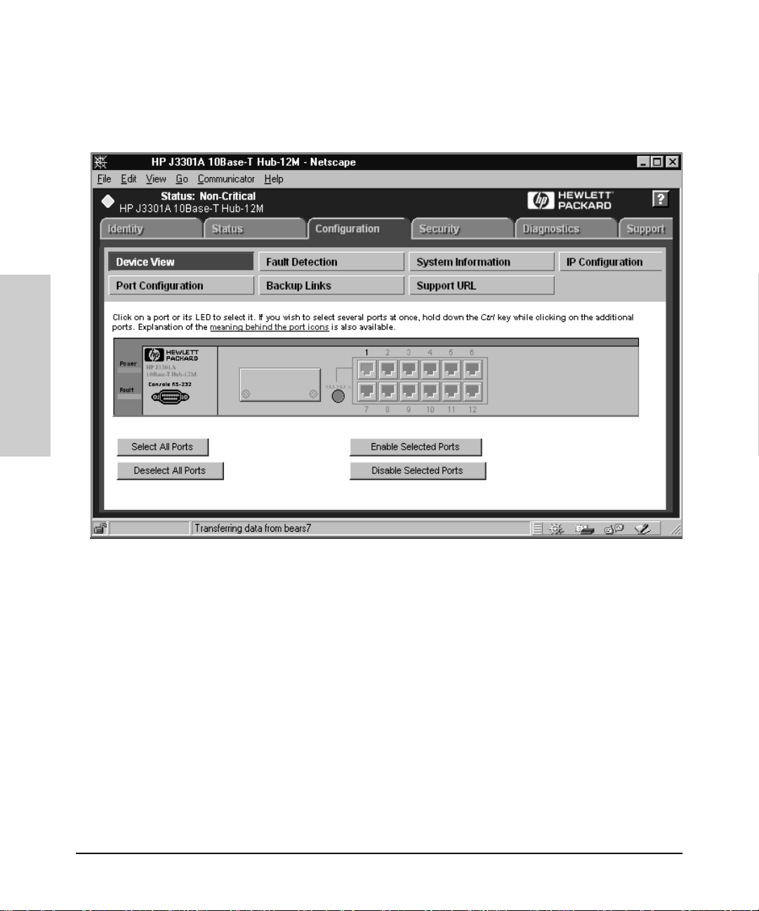
Figure 6-2. 10Base-T Hub-12M Device View
You can enable and disable individual ports (click on the port to select it), or
click on the Select All Ports button to enable or disable all the ports of a
device in one step.
For the switching hub, select a hub or card from the stack using the drop
down list at the top. The Closeup View for that hub or card will display.
To move selected ports to a partic ular segment:
1. Select the Move Selected Ports to Segment button.
2. Select a hub from the drop down list, then select the segment that you
want to move the port to.
3. Click on Apply Settings.
Page 41

Accessing Hub Features
Configuring Your Device
Click on the link “meaning behind the port icons” to view the port indicator
legend.
Configura tion - Fault Detectio n
The automatic fault detection feature protects your network from failing
because of problems such as network loops, defective cables, transceivers
and faulty network interface car ds. The Faul t Detection page lets you set the
sensitivity and actions that occur when a fault is detected on a port in your
network. For hubs, you can set the sensitivity for logging network problems
and disabling ports. The sensitivity settings are:
High Sensitivity: the device will act when a network problem of any
severity occurs . Netw o rk problems are automatically detected and entered
into the Alert Log.
Medium Sensitivity: the device will act when serious network problems
occur.
Low Sensitivity: the device will act only when severe network problems
occur. These are problems that may br ing the network down.
Never: The device will never take any actions regardless of the severity of
the problem.
Accessing Hub Features
6-7
Page 42

Accessing Hub Features
Accessing Hub Features
Configuring Your Device
Figure 6-3. Fault Detection Sensitivity Settings
Configura tion - System Information
The System Information page lets you enter a system name for the device,
the location of the device, and whom to contact in the event of a problem.
Configuri ng IP
Select the way that you want IP addresses configured for your network:
■ Manual - Set the IP address through the console.
■ Disabled - IP is disabled, there is no access to management or telnet. Not
Recommended.
■ Use Bootp - The Bootp protocol sets the IP address automatically.
Hub I P C onfig uration
If you select Manual, you must then enter an IP Address, Subnet Mask,
Default Gateway, and Time to Live for the device. If you select Bootp/DHCP,
the IP address will be assigned automat ically.
6-8
Switching Hub IP Configuration
For the switching hubs, you must select a segment to configure before you
select Manual or Bootp/DHCP. If you select Manual, you must then enter an
IP Address, Subnet Mask, Default Gateway, and Time to Live for the device.
If you select Bootp/DHCP, the IP address will be assigned automatically.
Characteristics of Bootp an d D C HP. The Bootp protocol is designed for
a network in which each h o st has a permanent network connection. It is not
adaptable to a mobile computing envir o n ment.
The Dynamic Host Configuration Protocol (DHCP) manages the allocation
of TCP/IP configuration information by automatically assigning IP
addresses.When a device connects to the network, it requests an address
from the DHCP server. In dynamic mode, the address is used by the devic e
for a specified period of time. The time period depends on the situation; one
device may only need th e ad d ress for an hour, while another device may use
the same address for severa l da ys. DHCP is more suitable in environments
where the number of IP addresses needed exceeds the number available. It
also allows a device to obtain i ts con f igu ration information, such as the IP
Address and Subnet Mask, in one message, reducing the demand on the
network.
Page 43

Accessing Hub Features
Configuring Your Device
A static IP address is a unique address that is assigned to one client only.
Static addresses are used for an extended time period.
Port Configuration
The Port Configuration page displays information about the hub ports. To
enable a port, select the port number in the page, then click Enable
Selected Ports. Use the Disable Selected Ports button to disable a port
or group of ports.
The information displayed is described in the table.
Table 6-3. Hub Port Configuration
Setting Description
Port The port number.
State The port can be on or off.
Connected Yes: A device is connected t o this port.
No: There is nothing connected to this port.
Partitioned: The node is disconnected from
the network and the traffic that the port
generates is lost.
Polarity Reversed: Some signals in the cab le
are revers ed due to a miswired cable.
Accessing Hub Features
Segment For switchi ng hubs, the segme nt that the port
Last Source Address The address of the last devi ce that sent
Security Violati o n States whether there is a sec urity violation
is on.
packets th rough this port.
or no violation.
Configuration - Backup Links
A backup link (hubs only) configures two ports on one hub to create a
redundant connection to another device. This provides a connection with
fault-tolerant capability for highly reliable networking. One port is
designated the primary port; the second port is the backup port. The backup
port becomes active only if the primary port becomes inoperative. Any of the
6-9
Page 44

Accessing Hub Features
Accessing Hub Features
Configuring Your Device
network ports (twisted-pair, ThinLAN, or AUI/Xcvr) can be used as the
primary port or backup port.
Figure 6-4. Setting Backup Links
You can create one or more backup links by selecting the Backup Links
button and clicking on the Add New Backup Link.. . button at the bottom of
that page. The parameters are describ ed in the table.
6-10
Table 6-4. Backup Link Parameters
Parameter Description
Status Displays which port is currently being used, a primary
port or a bac kup port.
Primary Por t A port that you can use as a primary port, or the port
that will be used during standard connection of a hub
and the connected device.
Backup Port The backup por t to be used if there is a failure on the
prim ar y port.
MAC Address The MAC address of the device that the primary and
backup ports are connected to.
Page 45

Table 6-4. Backup Link Parameters
Parameter Description
Accessing Hub Features
Configuring Your Device
Test Time The interval in seconds between test packets sent
between t he primar y port and t he receiv ing device. This
checks the i nt egri ty of th e li nk t o det er mine w het her t o
initiate a backup link.
Retries The m aximum number of tim es the p rimar y port ca n fai l
before th e backup port becomes active.
Configuring Load Balancing - Switching Hubs
Only the switching hubs pro vid e a lo ad ba lan cing feature to automatically
distribute the switching hub ports among the four segments to optimize
performance. For switching hubs with version A.01.01 firm ware th is feature
requires a switch module. For switching hubs with firmware versions later
than A.01.01, the hub can load ba lan ce with an external switch.
To access this feature, select the Load Balancing button. Click on the
Perform Automatic Load Balancing button. If you want to undo the load
balancing, select the Undo Last Load Balancing button.
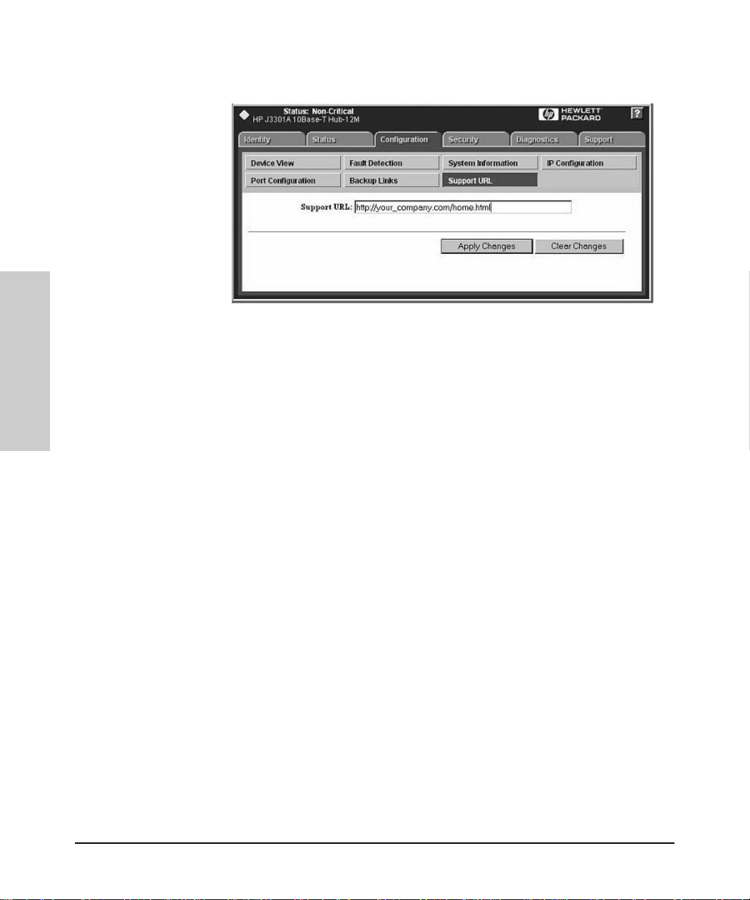
Configuration - Support URL
You can obtain support information by going to the HP Support site on the
World Wide Web. The URL is:
http://www.hp.com/go /procurve
Accessing Hub Features
Select Support.
6-11
Page 46
Accessing Hub Features
Accessing Hub Features
Configuring Your Device
Figure 6-5. Support URL
If you want to change the URL that is accessed when the Support tab is
selected, type in the new address and click on the Apply Changes button.
For example, you could change the URL to launch your site home page.
6-12
Page 47

Managing Switches
This chapter has information on:
■ Switch Status
■ Switch Identity
■ Configuration
■ Using VLANs
■ Support/Mgmt URL
Managing Switches
Switch Status
7
Switch Status
Status - Overview
To launch the Status - Overview page for a switch that is manageabl e by
browser, double-click on the switch symbol in the HP Network Node
Manager map or right-mouse-click on the symbol and select
Hub/Switch
.
Note: If the device is not manageable by browser you will see the
Closeup Vie w in a separate window (you must lau nch the Closeu p V iew
from the management station). Read the chapter “Management for
Non-Browserable Devices” or see the online help for more information.
The Status - Overview page is di vid ed into two areas, th e Graph area and th e
Alert Log area.
Monitor HP
Managing Switches
7-1
Page 48

Managing Switches
Switch Status
Figure 7-1. Switch Statu s Overview Page
Managing Switches
Graph Area
The bar graph gives a quic k overvi ew of the per formance o f the swit ch. Eac h
bar shows the highest percentage of transmitted (TX) or recei ved (RX)
traffic utilization for that port in the last five seconds .
The graph area proportionally depicts three attributes for each port:
■ Unicast packets - The percent utilization for packets that were not
addressed to a multicast or broadcast address.
■ Non-Unicast packets - The percent utilization of received non-unicast
packets (both b roadcast and multicas t). If there is a broadcast sto rm, only
the port receiving these packets shows high utilization, lettin g you quickly
pinpoint the problem.
■ Errors - The percent u t ilization for er ror packets received. A hi gh
percentage may indicate possible network problems.
Place the cursor over a bar in the graph to display the ex act p ercentages for
each attribute and the speed of that port. T he above graph di splays a high
percentage of non-unicast packets on port 2 (a 10 Mbps port) because this
port is running video. Port 5 is indicating some errors.
7-2
Page 49

Managing Switches
Switch Status
The graph only scal es to 40% utilization . Network utilization above this level
indicates serious performance problem s.
The graph also shows you if a port is active, disabled, or not connected.
Alert Log Area - Find/Fix/Inform
The “Find/Fix/ In form” capability of a device hel p s you proactively manage
your network by display ing trap s sent from the devi ce in an easi ly acce ssible
browser page. The device monitors counters and internal hardware
information. When a problem is discovered, such as loss of link, a problem
cable, or a broadcast storm, the Alert Log displays clear messages about the
problem. When you double-click on an alert in the Alert Log (or select the
alert and click on the Open Event button) , the Aler ts page displays more
information about the ale rt as wel l as some suggestions for fixing the
problem.
For example, the Aler t Log may disp lay th e alert “Cable Length”. The
following infor mation is available:
Description:
Packet loss detected on port 4. This may be due to an overextended LAN
topology or faulty hardware. The loss was detected on this port, but the
actual problem can be occurring elsewhere on this segment.
Solution:
Managing Switches
■ Ve ri fy the n etwork topol ogy is withi n IEEE 802 .3 topology standards. All
ThinLan coaxial cabl ing must be 185 mete rs or shor ter. No more than 4
repeaters are allow ed between any two stations in the network.
■ Insert bridges or switches between repeaters to extend network topology
if needed.
■ Check for faulty cabl ing, transceivers, and NICs.
■ Check for a Full/Half-duplex mismatch
Using the Find/Fix/Inform capability, the device can isolate a problem that
occurs on one port, preventing it from affecting the entire network.
See Alerts - Find/Fix/Inform
for information on reading and acknowledging
alerts.
7-3
Page 50

Managing Switches
Switch Status
Status - Por t Co unters
The Port Counters information for switches displays specific network
conditions or traffic. See the online help for more information about each
counter.
Status - Por t Status
The Port Status page (switches only) displays the operational status of each
switch port. The settings can be changed in the Configuration - Port
Configuration page.
The Port Status settings are described in the following table.
Table 7-1. Port Status Settings
Setting Description
Port The port number.
Port Type The network type of each switch port, for example, 100TX.
Managing Switches
Enabled Whether the port is enabled or disabled.
Link Status The port’ s curre nt operati onal status . Up means the port is working
correctly. Down means the port is disabled.
Current Mode The operational mode of the port.
• 10/100 Base TX - Can be 10 Mbit s hal f or ful l du plex or 100 Mbi ts
half or full duplex.
• 100 Base FX - Can be 100/full duplex or 100/half duplex.
• Gigabit - Can only be 1000 full duplex .
Flow Cont rol Indicates the current state of flow control for this port .
• 10/100TX, 10 FL, 100 FX:
– On - Flow control is enabled.
– Off - Flow co ntrol is dis abled (default).
• Gigabit:
– On (TX, RX) - Flow control is enabled on transmit and
receive .
– On (RX) - Flow control on receive only.
– Off (default) - Flow control is disabled.
7-4
Page 51

Table 7-1. Port Status Settings
Setting Description
Managing Switches
Identity
Bcast Li m it (not
available on
the HP J32 98 A or HP
J3299A)
The Broadcas t Limit, expressed as a percentage of broadcast
packets rel ative to the theor etical l imit. Any broadcast or multicast
traffic exceeding this limit w ill be dropped. A value of ze ro
indicates that no limit is to be applied. Valu es range from 0-99.
Identity
The Identity tab displays the following information about the switch:.
■ System Name ■ Produ ct Number and Name
■ System Location ■ Firmware Version
■ System Contact ■ IP Address
■ System Up-Time ■ Management Server
The Management Server field displays the address (URL) of the management
station where HP Hub & Switch Management was installed. This can be
changed by selecting the Configuration tab and displaying the Support/
Mgmt URLs page. Enter the URL in the Management Server URL field.
Online help can be displayed at any client when this URL is set correctly.
Managing Switches
Configuration
The Configuration p age lets you configure many device featu res, for
example, the sensitivity levels for Fault Detection.
Device View
There is a Device View for every managed HP switch. The Device View for
the HP ProCurve Switch 4000M looks like the following graphic. Use the
online help to obtain information about specific switch modules.
7-5
Page 52

Managing Switches
Configuration
Managing Switches
Figure 7-2. HP ProCurve Switch 4000M Device View
Configura tion - Fault Detectio n
The automatic fault detection feature protects your network from failing
because of problems such as network loops, defective cables, transceivers
and faulty network interface cards. Network problems are automatically
detected and entered in the Alert Log. The Fa ul t Detection page lets you set
the sensitivity levels for t he actions to be taken when a fault is detected on a
port in your network. Switches only have a sensitivity setting for logging
network problems. The sensitivity settings are:
High Sensitivity: The devi ce will make an entry in th e Alert Log (located in
the Status tab) when a network problem of any severity o ccu rs.
Medium Sensitivity: The device will make an entry in the Alert Log when
serious network problems occur.
Low Sensitivity: The device will make an entry in the Alert Log only when
severe network problems occur. These are problems that may bring the
network down.
7-6
Page 53

Managing Switches
Configuration
Never: The device will never make any en tries in the Alert Log regardless of
the severity of the problem.
Configura tion - System Information
The System Information page lets you enter a system name for the device,
the location of the device, and whom to contact in the event of a problem.
Configuration - IP Configuratio n
Select the way that you want IP addresses configured for your network:
■ Manual - Set the IP address through the console.
■ Disabled - IP is disabled, there is no access to management or telnet. Not
Recommended.
■ Use Bootp - The Bootp (or DHCP) protocol sets the IP address automat-
ically.
If you select Manual configuration, you can change the IP address, a subnet
mask, and a default gateway for the device.
Some switches let you configu re an IP address for every VLAN you have
created.
7-7
Managing Switches
Page 54

Managing Switches
Configuration
Managing Switches
Figure 7-3. Switch IP Configuration
Characteristics of Bootp an d D HC P. The Bootp protocol is designed for
a network in which each host has a permanent network location. It is not
adaptable to a mobile computing envir o n ment.
The Dynamic Host Configuration Protocol (DHCP) manages the allocation
of TCP/IP configuration information by automatically assigning IP
addresses.When a device connects to the network, it requests an address
from the DHCP server. In dynamic mode, the address is used by the devic e
for a specified period of time. The time period depends on the situation; one
device may only need th e ad d ress for an hour, while another device may use
the same address for severa l da ys. DHCP is more suitable in environments
where the number of IP addresses needed exceeds the number available. It
also allows a device to obtain i ts con f igu ration information, such as the IP
Address and Subnet Mask, in one message, reducing the demand on the
network.
A static IP address is a unique address that is assigned to one client only.
Static addresses are used for an extended time period.
7-8
Page 55

Managing Switches
Configuration
Configura tion - Port Configur ation
The Port Configuration page displays information about the switch ports.
The settings are explaine d in the follo wing table. To modify a port setting,
click on a port then select the Modify Selected Ports button. Modify
multiple ports at one time by using Ctrl-Click to select the desired ports.
Note: Some switches support trunking. For information on trunking,
see the online help fo r tha t de vice .
Figure 7-4. Switch Port Configuration
Managing Switches
7-9
Page 56

Managing Switches
Configuration
Table 7-2. Switch Port Configuration Settin gs
Setting Description
Port The port number. The port may be appended with on e of the
following:
• Trkx - The port trunk to w hich this por t belongs
• Mesh - The port has been assigned to a switch mesh domain
• MP - The port is a Monitor Port
Port Type The MAC layer type, for example, 100VG or FDDI.
Enabled Whether the por t is enabled or disabled.
Managing Switches
Config Mode The speed and duplexing for the port. Auto mode will negotiate
with the de vice on that por t to determine the mode.
Click on Modify Selected Ports t o change the mode.
Flow Contr ol Indicates the current state of flow control for this port. When
disabled, the port does not generat e flow control packets and
drops any flow control packets it receives.
• 10/ 10 0T X , 10 FL , 10 0 FX :
– On - Flow control is enabled.
– Off - Flow co n trol is dis a bl ed (defaul t).
•Gigabit:
– On (TX, RX) - Flow control is enabled on tran sm it and
receive.
– On (RX) - Flow control on receive only.
– Off (default) - Flow control is disabled.
Bcast Limi t The Broadcast Limit, ex pressed as a pe rcentage of broadcast
packets relative to the t heoreti cal limit . Any br oadcast or multicas t
traffic exceeding this limit will be dropped. A value of zero
indicates that no limit is to be applied.Values range from 0-99 .
Configuration - Assigning a Monitoring Port
The Monitor Port tab (only found on switches) lets you select a “Monitoring
Port” that you can use with a network analyzer to monitor other ports on the
switch. For the HP J3298A and HP J3299A you can only choose the
Monitoring port and the port to be monitored. For other switches you can
choose to have all the ports for one VLAN monitored, or you can select
individual ports to be monitored. See the online help for information on
specific switche s.
7-10
Page 57
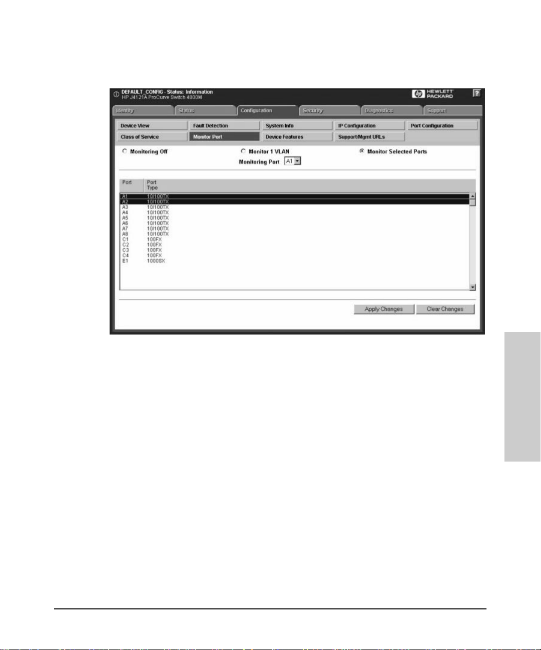
Managing Switches
Configuration
Figure 7-5. Selecting a Monitoring Port on a Switch
Using VLANS
Virtual LANs, or VLANs, are generally defined as broadcast domains created
with software rather than being a functio n of the hardware. They can be
viewed as a group of end nodes, possibly on different physical LAN
segments, that can communicate with each other.
As networks expand, more routers are needed to separate users into
broadcast domains. Latency degrades network performance, and is a special
problem for multimedia applications. Switches using VLANS create the same
division of the network into broadcast domains, but do not have the latency
problems of a router. Switches are also a more cost-effective solution. You
can create virtual LANs by assigning selected ports of your HP switch to a
VLAN.
The benefits of VLANs include:
■ Grouping users into logical networks for increased performance
7-11
Managing Switches
Page 58

Managing Switches
Configuration
■ Providing an easy, flexible, less cos t ly way to modify logical gr oups in
changing environments
■ Preserving curren t investment in equipment an d cabling
■ Allowing administrators to “fine tune” the network
■ Providing independence from the physical topology of the network
VLANs make large networks more manageable. You can group users
according to some shared characteristic, such as a common busin ess
function or a common protocol. A single switch may have severa l
independent VLANs within it.
Note: VLANs must be created with the device console.
Configuration - Device Features
The Device Features page (onl y fo und o n swi t ch es) lets you set some or all
of these features:
■ Automatic Br oadcast Cont rol (ABC)
■ Multicast Filtering (IGM P)
■ Spanning Tree
Managing Switches
Automatic Broadcast Control (ABC)
Automatic Broadcast Control (ABC) is a feature that controls broadcasts
through IP/IPX Broadcast Reduction. IP/IPX Broadcast Reduction reduces
the number of broadcasts propagated through the network.
Using ABC, th e switch acts as a proxy se rv er, replying to Address Resolut io n
Protocol (ARP) requests, Nearest Server Query (NSQ) requests, and
GetLocalTarget reques ts on behalf of the destination node . An ARP cache
(learned address table) is created for each subnet allowing the switch to
proxy reply with the resolved MAC address instead of forwarding the
requests out all ports. This limits the broadcasts within the switching
domain. The Service Advertising Protocol (SAP) table performs the same
function in an IPX network. By using these tabl es, the switch can resolve
addresses for any node in the network that it already knows about.
Routing Information Protocol. The switch also intercepts Routin g
Information Protocol (RIP) and SAP broadcasts and forwards these only to
ports where routers and servers have been de tected . This also reduces the
number of broadcasts on the network.
7-12
Page 59

Managing Switches
Configuration
For example, if User A sends out a broadcast message to connect to its
server, the request is sent out of all ports on the swit ch . When the serv er
responds to User A, the switch intercepts the response and learns that the
server is on that port. When User B sends a request to the same server, the
switch already knows which port that server is on and sends that
information to User B, just as if the server had responded to the request.
User B’s request is not broadcast out any of the switch ports.
Enabling Broadcast Control for IP
The IP protocol uses Address Resolution Protocol (ARP) packets to find the
MAC address of a node that corresponds to the network layer address. When
Broadcast Contr ol is enab led, the switch intercepts the ARP packet on its
way to the destination node. If this destination is unknown to the switch, the
switch floods the ARP request to all ports. When the destination port
responds, the switch stores information about the destination MAC address
and layer 3 address in its ARP cach e. T hi s info rmation allows the switch to
proxy a reply containing the MAC address of a destination to the source of
an ARP request. The source can then send a unicas t pac ket directly to the
destination. The amount of broadcast traffic has been decreased.
Automatic IP RIP Control. To further reduce broadcast traffic, you can
check Automatic IP RIP Control. IP RIP packets are sent out perio d ically
(every 30 seconds) to distribute routing information. By enabling Automatic
IP RIP Control, the switch will only forward RIP packets out the ports on
which RIP packets have been received. Since routers are the onl y de vices
that generate RIP packets, this ensures that RIP packets are only sent out
ports with routers attached to them. When this feature is not enabled, IP RIP
packets are forwarded to all ports.
Managing Switches
Enabling Broadcast Control for IPX
The IPX protocol broadcasts all of its known routes and services every
minute by using IPX, RIP and Service Advertising Protocol (SAP) packets.
When servers are booted up, they advertise their services using SAP. These
frames must be forwarded by routers, which maintain a database of this
information, allowing clients on the network to obtain the internetwork
addresses of the servers where they can access services.
Automatic IPX RIP/SAP Control. To further reduce network traffic, you
can check the Automatic IPX RIP/SAP Control check box. The switch will
intercept RIPs and SAPs, broadcasting them only to ports where IPX routers
or servers have been detected, or to ports that have been configured to
7-13
Page 60

Managing Switches
Configuration
transmit RIPs or SAPs. When this feature is not enabled, IPX RIP/SAP
packets are forwarded to all ports.
Automatic IP Gateway Configuration
When Automatic IP Gateway Configuration is enabled, the swi t ch wil l
modify replies from the DHCP server so that the Default Gateway IP address
of a client becomes the client’ s own IP address. This is useful in a
multinetted environment (where more than one IP network is configured in
a single broadcast domain).
See Routing Information Protocol.
Internet Gro up Management Pr otocol (IGMP)
Multimedia and email applications need the ability to communicate to
multiple destinations efficiently. IP multicasting allows host s to d yn amically
register for sending or receiving multicast traffic.
The Internet Group Management Protocol is a method for automatically
controlling multicast traffic through the network. Using multicasting,
applications can send one copy of a packet addressed to a group of
computers that wish to receive it. This method is more efficient than sending
a separate copy to each node. Other advantages of multicasting include:
Managing Switches
■ information delivered in a timely , synchronized manner because all desti-
nation nodes receive the same packet
■ information can be sent to destinations whose addresses are unknown
■ reduces the number of packets on the network because only one multicast
packet is sent.
IGMP uses multicast queriers and hosts that support IGMP to manage
multicast traffic on the network. It specifies how the host informs the
network that it is a member of a multicast group. A set of queriers and hosts
that send and re ceive data from the same set of sources is a multicast group.
The HP switches have a standards-based IGMP implementation. The
switches process IGMP packets by learning which of the switch’s interfaces
are linked to hosts that are members of multicast groups and multicast
routers. It limits multicast traffic by monitoring the IGMP traffic to learn
which hosts are in which multicast groups, then allowing IP multicast traffic
to be sent only to ports with valid host group members.
When a switch receives an IGMP packet, it u pdates the internal IP multic ast
forwarding table with the IGMP membership read from that packet. The
7-14
Page 61

Managing Switches
Configuration
switch then sends the packet to the ports with members of the destination
multicast group.
Special multicast routers/queriers communicate by using three message
types - query, report, and leave group. The query message, sent by a querier,
is used to discover which network interfaces belong to a multicast group.
Each host responds to th e query message with a report m essage that tel ls the
querier the host is a member of the multicast group. The host also can send a
report message to join a group or a leave message to leave a group.
Note: Using the console you can designate specific ports to always or
never forward multicast packets.
Forward with High Priority
When “Forward with High Prior ity” is checked, any IGMP packets received
by the switch will be forwarded in a prioritized manner, preceding packets
with normal priority.
The Spanning Tree Protocol
The Spanning Tree Protocol (IEEE 802.1d) maintains a loop-free topology in
networks with redundant bridges or switches. The spanning tree devices
determine which devices will be active and which will be backups so that no
two nodes in a network have more than o ne active p ath between them at any
time. The Spanning Tree Protocol uses the most efficient path between
segments. If a bridge or switch fails, the other bridges and switches
reconfigure the network automatically. When the problem is repaired, the
bridges and switches automatically return to the original network
configuration.
Managing Switches
7-15
Page 62
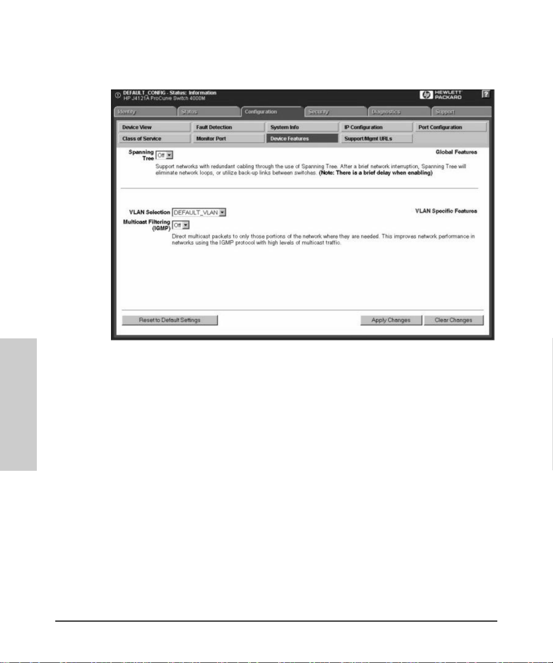
Managing Switches
Configuration
Managing Switches
Figure 7-6. Switch Device Features
If you have configured VLANs for the switch (you must do this with the
device console), sel ect a VLAN for which th e featu res will apply.
Configura tion - Support/Mgm t U R Ls
Support URL
To go directly to the HP Support Site on the World Wide Web, click on the
Support tab. You will launch the site indicated by the URL that has been
entered in the Configure - Support/Mgmt URLs page. By default this is the HP
Network City support site. The Network City site has information about HP
devices, FAQs, firmware upgrades, white papers on current technologies,
and much more. This URL is:
http://www. hp.com/go/procurve
7-16
Page 63
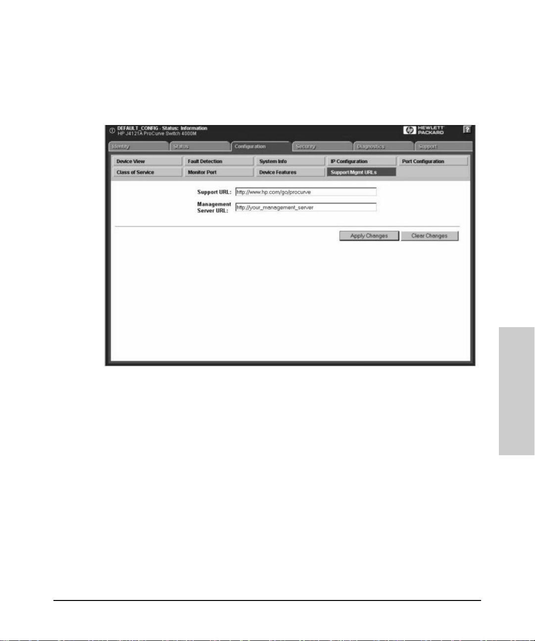
Managing Switches
Configuration
If you want to change the URL that is accessed when the Support tab is
selected, type in the new address and click on the Apply Changes button.
For example, you could change the URL to launch your site home page.
Figure 7-7. Setting URLs for Support and the Management Station
Management Server URL
Enter the URL for your management server. This will let you display the
online help at any client in the network.
Note: This field will contain the address for the HP Network City web
site by default. If you do not change it, the online help will be loaded
from the HP Network City site.
7-17
Managing Switches
Page 64

Managing Switches
Configuration
Managing Switches
7-18
Page 65

Setting Up Security for a Device
It is advisable to set up security for your devices to prevent unauthorized
access to the device or the network. You can configure device security to
prevent unauthorized use of certain parts of the network by certain nodes,
and to keep unwanted traffic out of certain parts of the network.
Note: For older HP devices that cannot be managed with a Web
browser, read the chapter “Management for Non-Browserab le Devices”
or see the online help.
This chapter contains information on:
■ Device Passwords
■ The Function of Community Names
■ Port Security
■ Address Selection
■ Eavesdrop Prevention
■ Setting Security Policy
■ The Intrusion Log
Setting Up Security for a Device
Device Passwords
8
Device Passwords
Assigning passw ord s to devices helps limit acces s to authorized persons. In
the Security page, select the
for the device.
Device Passwords
button to assign passwords
8-1
Setting Up Security for a
Device
Page 66

Setting Up Security for a Device
Device Passwords
Figure 8-1. Assign Passwords to a Device
There are two categories of passwords:
■ Operator (Read only) : The Operator can view all pag es except the Security
pages. For switches, this password is the same as the console password.
■ Manager (Full Read and Write permissions): The Manager can view all
pages and make any changes in any page. The Manager name and password are the same as th e name and password used in accessing the device
through the console or a telnet session. If you change the password in this
page, the console password is overwritten and becomes this password.
Enter the desired names and passwords. The minimum recommended setup
is to have one Manager password. Cl ick o n the Apply Changes button. If you
want to clear these changes select the Clear Changes button. This will not
clear any changes that you have alr ead y applied to the device.
Device
Manager/Opera to r Passw ord Combinations
The level of protection and the acce ss granted to the device depends on
Setting Up Security for a
what passwords are set at what levels. The table b elo w descr ibes the
settings and their consequences.
8-2
Page 67

Table 8-1. Manager/Operator Password Combinations
Setting Up Security for a Device
Device Passwords
Passwords Read
Protected
Manager password set
Operator password not set
Manager password set
Operator passw ord set
Manager password not set
Operator passw ord set
Manager password not set
Operator password not set
N/A Yes Anyone can get Read Access, but only th e
Yes Yes Both the Manager and the Oper ator have
Yes Yes The Operator has both Read and Write
N/A N/A Anyone can get Rea d and Write Access to
See the online help for inf ormation about non-browsera b le d evices.
The Funct ion of Commun ity Names
A community defines aut he ntication and access control between an SNMP
agent and a management station. The communi ty na me functio ns as a
password in that management statio ns must use the community name for all
Get and Set operations. This is different and separate from the Operator and
Manager passwords, which protect access to the browser interface and
console settings.
Write
Protected
Results
Manager can r ead and writ e to the de vice.
Recommended m inimum setting.
Read Access, but only the Manager has
Write Access. Everyone else is shut out of
the device. Recommended setting.
Access becaus e Write Access has not
been reserv ed for the Mana ger.
the device. Not recommended.
To set a Community Name for a device:
1. Right mouse click on a device symbol and select SNMP Configure HP
Hub/Switch
2. Enter the passwords in the Set SNMP Passwords (Communiti es) p age.
Setting Up Security for a
Device
8-3
Page 68

Setting Up Security for a Device
Port Security
Port Security
Y ou can assign security levels on hubs port by port. Select the Port Security
button to view the current settings fo r each po rt.
Figure 8-2. View the Secu rity Settings for Each Port.
Address Sele ctio n
Address Selection refers to how the authorized address for a port is
discovered. The three settings are explained in the table.
Table 8-2. Address Selection
Setting Description
Continuous The devi ce l ea rns the a ddr ess of th e dev ice att ac hed to the p or t and
makes it th e authorized MAC address. If a different device is later
Device
Setting Up Security for a
8-4
attache d to the port, th e new address i s learned and becomes the
authorized address.
Page 69

Table 8-2. Address Selection
Setting Description
Setting Up Security for a Device
Port Securit y
First Heard
Assigned Enter the address of the devic e that is authorized to be attached to
To set the Address Selecti o n:
1. Click on the Set Security Policy for Select ed Ports button.
2. Select a setting from the Address Selection drop down list.
3. Click on Apply Settings.
The devi ce l ea rns the a ddr ess of th e dev ice att ac hed to the p or t and
makes it th e authorized MAC address. If a different device is later
attache d to the port, th e new address i s registered as an “intr uder
address”; a security violation has occurred and the port is
automatically disabled.
the port. I f a diff erent device i s att ached to th e port , the n ew addre ss
is registered as an “intruder addr ess”; a security violation has
occurred and the port is disabled.
Authorized Address
The Authorized A ddress field contai n s the MAC address of the d evice that is
authorized to be attached to the port.
Eavesdrop Prevention
Eavesdrop Preventi o n is a feature of several HP devices that stops a
computer or other device from seeing network traffic that is not intended for
that port. When Eavesdrop Prevention is configured on a port, the port's
authorized MAC addre ss is compared with the destination ad d re ss of any
outbound packets.
Set the Eavesdrop Prevention parameter for a port or group of ports by
clicking on the Set Security Policy for Selected Ports button and selecting
“yes” from the Prevent Eavesdropping drop down list.
Send Alarm
If you set the Send Alarm parameter to “yes”, a trap will be sent to the
management stat ion when an u nrecogn ized ad dress is re ceived . Set the Send
Alarm parameter for a port or group of ports by clicking on the Set Security
Policy for Sel ec t ed Po rts button and selecting “yes” from the Send Alarm
drop down list.
8-5
Setting Up Security for a
Device
Page 70

Setting Up Security for a Device
Set Securit y Policy for Selected Ports
Note: In order for traps to function, you must also set the trap in the
Thresholds dialog box , as fol lows:
1. Using the right mouse button, click on the device symbol in the HP
Network Node Manager map.
2. Select
3. Select the Thresholds tab and set the thresholds for the traps you are
4. Select the Trap Receivers tab and set the management stations that can
5. Select the Auth orized Man agers tab a nd set the management stati ons that
SNMP Configuration
interested in receiving.
capture traps.
can se n d and receiv e S N MP re quests f o r th e devi c e.
.
Disable Port
If the Disable Port parameter displays “yes”, the port may be disabled when
an unrecognized address is received. Disabling the port depends on the
Address Selection parameter that you have chosen. The settings
and
Assigned
port will not be disabled when a new address is learned if the setting is
Continuous
will disable the port if a new address is heard on that port. The
.
First Heard
Set Security Policy for Selected Ports
You can set the security policy port by port, or by selecting a group of ports.
Select one port by clicking on the entry in the Port Security page. T o select
more than one port, you can Ctrl-click on each port you want to include, or
to select a range of contiguous ports, click on the first port in the range, then
shift-click on the last port to be included. Click the
Selected Ports
Device
Setting Up Security for a
8-6
button. Select the parameters that you want to assign.
Set Security Policy for
Page 71
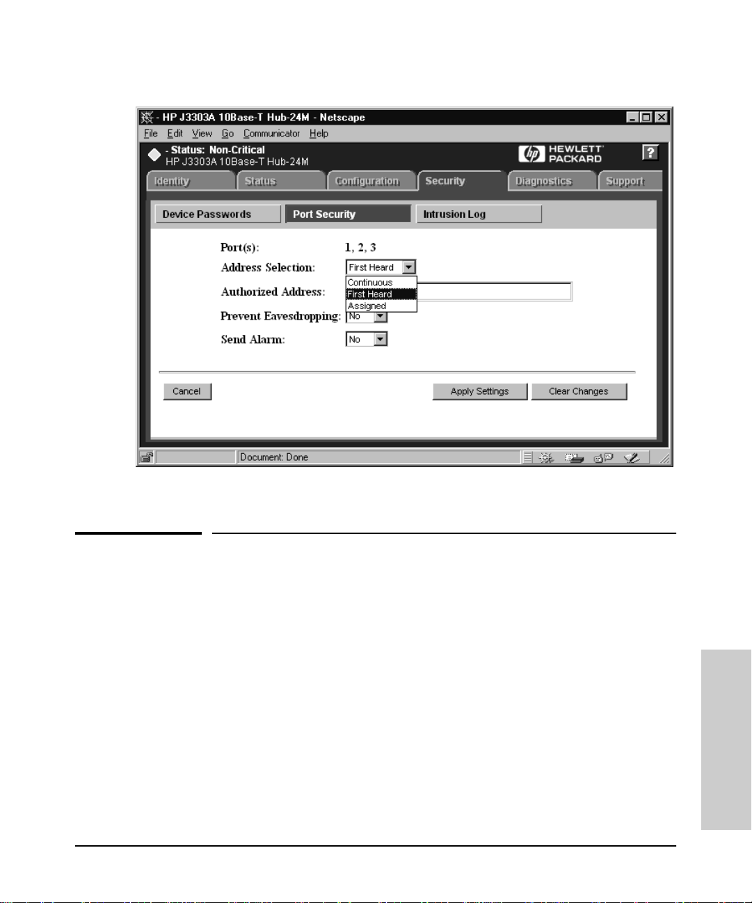
Setting Up Security for a Device
The Intrusion Log
Figure 8-3. Setting Security Policy for Several Ports
The Intrusion Log
The Intrusion Log page lets you view security intrusi o n s (v io lations) of a
device. The infor mation displayed include s:
■ Port - The ports that have detected attempts of unauthorized access.
■ Intruder Address - Address of the intruder. The IP a ddress is displayed for
SNMP agent violati ons. The MAC addres s is displayed for port violati ons.
The port violation must be cleared before another port violation will
display .
■ Date/Ti me - Date and time the security intrusion occurred.
8-7
Setting Up Security for a
Device
Page 72

Setting Up Security for a Device
The Intrusion Log
Device
Setting Up Security for a
8-8
Page 73

Performing Diagnostics
Performing a Ping/Link Test
Performi n g Di agnos tics
Using HP Hub & Switch Management, you can help isolate faults by running
device self-tests, Link tests, and Ping tests (IP networks).
Note: For older HP devices that cannot be managed with a Web
browser, read the chapter “Management for Non-Browserab le Devices”
or see the online help.
This chapter includes information on:
■ Performing a Ping/Link T est
■ Rebooting a Device
■ Resetting a Hub to Factory Default Settings
■ Producing a Configuration Report
9
Performing Diagnostics
Performing a Ping/Link Test
You can isolate faults by running Link tests or Ping tests (IP networks).
Select the
a test for sending test packets to, or through, a device in order to verify the
path between two network devices. In the
field enter the IP address or MAC address of th e dev ice for which you want
to test the connection. Specify th e n umber of pack ets to send and the
timeout (in seconds) for each test. Click on the
Click on the
Diagnostics
Stop
tab and click on the
button to stop the test.
Ping/L i n k Test
Destination MAC/IP Address
button to start the test.
Start
button. Choose
9-1
Page 74

Performing Diagnostics
Performing Diagnostics
Rebooting a Device
9-2
Figure 9-1. Ping/Link Test
The number of successes or failures of the test packets reaching the
Destination IP or MAC Address are displ ayed at the top of the page. A failu re
means that either the device at the destin atio n ad d ress did not respond
within the timeout specified, or the data returned from the device indicated
an error.
The Defaults button will reset the Number of Packets to Send and the
Timeout value to the default values of 10 packets and 1 second, respectively.
Rebooting a Device
Rebooting the device is the same as poweri ng off the device. Network
operation w ill be interrupt ed while the device ini t ializes.
Page 75

Performing Diagnostics
Resetting a Hub to Factory Default Settings
Resetting a Hub to Factory Default
Settings
Resetting the hub to the factory default settings removes any configuration
changes that you have made since installing the device , an d rest o res the
factory defaults. The IP address is also removed; you must enter an IP
address before the device will o p erate on your network, unless you have
Bootp or DHCP.
Producing a Configuration Report
The Configuration Report displays information about the current settings on
your device. You can use your browser’s capabilities to print a copy of the
report or save it to a file. See the online help for a more detailed explanation
of this report.
Performing Diagnostics
9-3
Page 76

Performing Diagnostics
Performing Diagnostics
Producing a Configurat ion Report
9-4
Page 77

HP Hub & Switch Managem en t Admin
HP Hub & Switch Management Admin is an administrati on utili ty that all ows
you to set specified configuration and control parameters used by HP Hub &
Switch Management for OV -UX. HP Admin is automati cally installed when you
install HP Hub & Switch Management for OV-UX.
This chapter includes the following topics:
■ Starting HP Hub & Switch Management Admin
■ HP Admin Pa ra met e rs
Starting HP Hub & Switch Management Admin
10
Management Admin
HP Hub & Switch
You can start HP Admin in the follow in g wa ys:
■ Enter /opt/HPASA/bin/admin at the command line prompt.
■ In an OpenView submap, display the
& Swit ch Admin
.
Options
menu and select
HP Hub
HP Admin Parameters
The parameters that you can set in HP Admin are grouped into these categories:
■ Network parameters
■ User Interface parameters
■ Graph options parameters
■ Printer Configuration parameters
■ OpenView Configuration options
10-5
Page 78
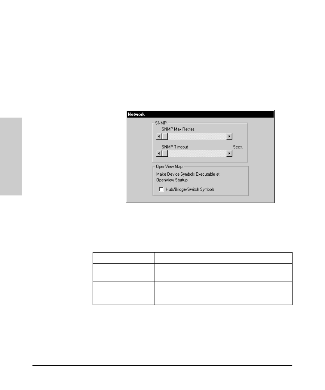
HP Hub & Switch
HP Hub & Switch Management Admin
HP Admin Parameters
The parameters are briefly described below. For more information, see the HP
Admin online help.
Network P a ram e ters
Network parameters enable you to set values and behavior for network device
communication and Clo seup View activity . The par ameters for network device
communication are described in the following table.
Management Admin
10-6
Figure 10-1. Setting Network Parameters
Table 10-1. Network Parameters
Parameter Description
SNMP Max Retries Specifies th e num ber of times w ill retr y an SNMP request to
get a resp onse. The range is 1-5 times. The default is 3.
SNMP Timeout Speci fies the ti m e (in seconds) that HP Hub & Switch
Management wi ll w ait f or a repl y on e ach req ues t. Th e rang e
is 1-6 seconds. The default is 5.
HP OpenView Device Symbols
There are two states for an OpenView dev ice symbol on an OpenView map,
explodable and executable. When the device symbol is in the explodable
state (no box appears around it) and you double-click on it, a submap showing
Page 79

HP Hub & Switch Management Admi n
HP Admin Parameter s
the attached devices appears. When the device symbol is in the executable
state (a box appears around the symbol) and you double-click on it, a Closeup
View of the device appears.
HP Admin gives you two ch eck boxes i n the Make Device Symbols Execu t-
able at OpenView Startup section that all ow you to change the state of the
device symbols the next time OpenView is started. If the check box for Hubs/
Bridges/Switches is enabled (box is darker), the next time that OpenView is
started the associated device symbols w ill be executable. If th e ch eck box is
not enabled, the next time that OpenView is started the state of the symbols
will not have changed. If the symbols were in the ex ecu tab le state when you
exited OpenView, they will remain in the executable state. If the symbols were
in the explodable state when you exited OpenView, they will remain in the
explodable state.
Note: When an HP Admin check box is disabled, no change in the
existing device symbol stat e occur s when OpenView is restarted.
Note: If you enable a Hub/Bridge/Switch chec k box while OpenView is
running, the change in symbol state to executable will not occur until
OpenView is restarted. OpenView checks these parameters at startup.
Management Admin
HP Hub & Switch
User Interface Parameters
User Interfac e parameters enable you to set the vi sual environment and object
attributes in the HP Hub & Switch Management Device Views.
10-7
Page 80

HP Hub & Switch
HP Hub & Switch Management Admin
HP Admin Parameters
Table 10-2. User Interface Parameters
Parameter Description
User Level • This paramete r contro ls HP Hub & Switch Manag ement
messages to the user. There are 3 user-level
parameters:
• Beginner (User Level 1, default): Message boxes will
notify the user when device param eter modifications
have completed. Also, the user will be warned about
changes t hat are about to be made to a device or to a
local f ile. The us er will be a llowed t o canc el the change.
• Interm ediate (User Level 2): The user will be warned
about cha nges tha t are about t o be made to a dev ice or
to a local file. The user will be allowed to cancel the
change.
• Advanced (User Level 3): There will be no notificatio n
or confirmation messages.
Port Statistics Interval This parameter is set by a slidi ng bar and spe cifies the
Management Admin
sampli ng interval (in seconds ) for the port statistics
graphical displays. The default is 5 seconds.
Show T ool Bar Banner Thi s p ara met er spe ci fies whet he r t he tit le of e ach Toolbar
Closeup Status Interval This parameter is set by a sliding bar and specifies t he
Closeup Gau ge Interval This parameter is set by a sliding bar and specifies the
Thresholds: Activity% Sliding bars are used t o specify the levels at which the
Thresholds: Collision%; Hi gh
Priority
button is displayed in the graphical control panels
(Closeup Views) a s the mouse cur sor is passed over the
button . The default is for button titles to be displayed.
sampli ng interval (in seconds ) for port status in the
graphical cont rol pane ls ( Closeu p View s). Th e defa ult is 10
seconds .
sampli ng interval (i n seconds) fo r the “LAN Activit y%” and
the “Col lision%” gauges in the graphical con trol panels
(Closeup Views). The default is 5 seconds.
“LAN Activity%” gauges in graphical control panels
(Closeup Views) c hange color from green to yellow, and
from yellow to red. The de fault levels are 30% and 50%,
respectively.
Sliding Bars are used to specify the levels at which the
“Collis ion% ” gauges i n gra phical cont rol pa nel s (Clos eup
Views ) change color fr om green to yell ow, an d from yellow
to red. The default levels are 30% and 50%, respectively.
10-8
Page 81

HP Hub & Switch Management Admi n
HP Admin Parameter s
Graph Options Parameters
HP Admin graph options parameters enable you to control different aspects
of the graphing feature. The parameters are described in the following table.
Table 10-3. Graph Option Parameters
Parameter Description
Graph Log For mat This parameter all o w s you to choose the format o f the
inform ation logg ed to a graph log fi le fr om the Gr aph Cou nte rs
function.
• T ext : Data wil l be logged to the l og file as stra ight AS CII text .
The default is “Text”.
• Spreadsh eet-Tab: Data will be logged to the l og fi le as AS CII
text sep arated by ta bs for ease of exporting the data to
spreadsheets that use tabs.
• Spreadsh eet-Comma: Data will be logged to t he file as ASCII
text sep ara ted by commas for ease of expo rti ng th e dat a to
spreadsheets that use commas.
Management Admin
HP Hub & Switch
Graph Digits to Display This param eter is set by a sliding ba r and specifies the
Graph Interval This p a rameter is set by a sl iding bar and specifies the default
Graph Log Fi le The parameters set in this section specifies the fi le name for
Enable Graph Sensitive
Scaling
maximum num ber of digi ts disp layed for a counter value before
displaying the value in scientific notation. The default is 4.
sampling time interval (hh: mm:ss) for graphing . The minimum
setting is 1 second. The maximum value is 9999:59:59. The
defaul t is 20 seconds.
the graph log file and the size of the log file.
Default log file name is “graphs.log”
Default l og fi le s iz e is 12 800 0 b ytes. T he mi nim um log f ile si ze is
10000 byt es. The maxim um is 2
This parameter controls the scaling of graphs. The default is
“disabled”.
If enabled , the “Y -axis” graphing sca le will automatically adjust
to display only the ran ge of values needed. A more detailed
view of th e graph will be displayed.
If disabled, the “Y-axis” graphing scale will start at zero. The
upper limit will aut om atically a djust to the power of 10 as
needed.
32
-1 bytes.
10-9
Page 82
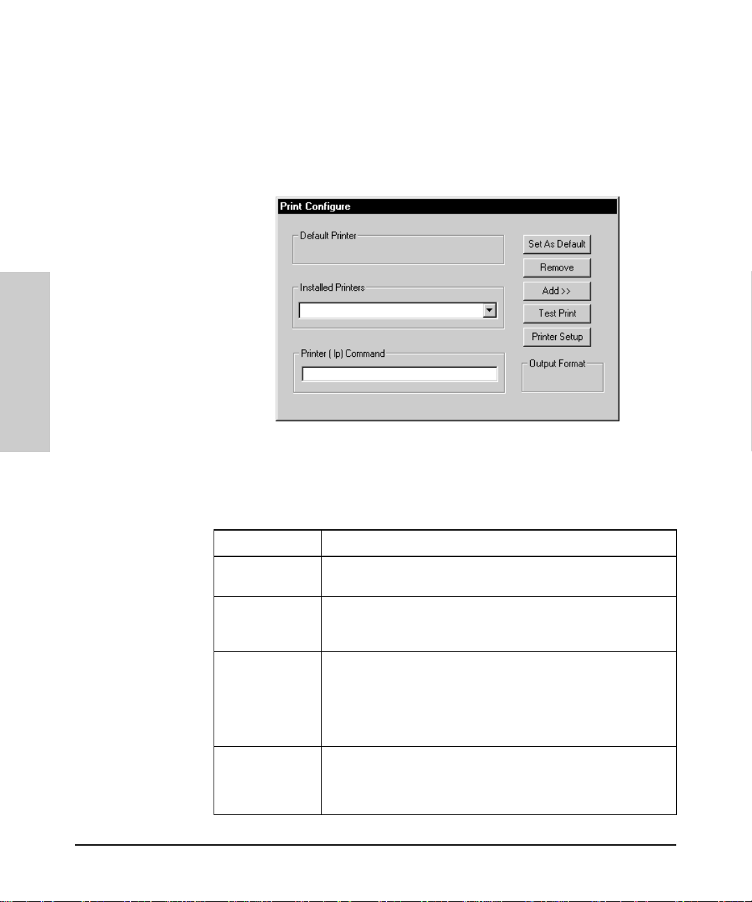
HP Hub & Switch
HP Hub & Switch Management Admin
HP Admin Parameters
Printer Conf iguration Parameters
Network management applications that implement printer support on X
Window systems can use the Print Configuration dialog box to configure
printer configuration parameters.
Management Admin
Figure 10-2. Printer Config uration
Table 10-4. Printer Configuration Parameters
Parameter Description
Default Printer Displays the current default pr inter name. This printer w ill be used if
the choice of printers is not overridden.
Installed Printers Provides a sorted list of all currently configured printers. The
currently displayed printer updates the “lp command” and “Output
Format” boxes.
lp command Shows the device name and port for the curre ntly selected printer,
Output Format Identifies th e dr iver ty pe o f the p ri nter tha t i s cur ren tly s el ect ed. T he
and the lp co mmand string . The lp command is used to redir ect the
output to a specific devi ce—print ed output is “piped” into the
command specified by the lp command text. Your can modify the lp
command string to meet your pri nter requirements. See your HP-UX
man pages for more information on the lp command.
lp command string must be compatible wi th the format identif ied in
this box. You may need to edit the lp command string or choose
another printer.
10-10
Page 83

Table 10-4. Printer Configuration Parameters
Parameter Description
HP Hub & Switch Management Admi n
HP Admin Parameter s
Set As Default Sets the pr inter se lect ed in the “Inst alled Pr inte rs” box as the de fault
printe r .
Remove Removes a select ed printer from the “Installed Printers” li st.
Add Displays a list of supported printers that you can sel ect and add to
the “Installed Printers” list.
Test Print Prints a sample test file to a selected printer if the printer
configu ration has been saved (see the OK button).
OK Saves the configu rati on and ret urns to t he mai n HP Admin dialog box.
Cancel Returns to the main HP Admin dia log box without saving
configuration changes.
Help Accesses the HP Admin online help system.
OpenView Configurat ion Options
You can change the way that OpenView and HP Hub & Switch Management
interact by setting these options:
■ ForceMapUpdates
■ NoMapWalk
■ Trace
■ Distributed Console
Management Admin
HP Hub & Switch
These options provid e advanced tun ing capabiliti es for kn owledgeable u sers
of OpenView. You do not need to use them to run the application.
Any changes that you make will not take effect until the next time that
OpenView (ovw) is run.
10-11
Page 84
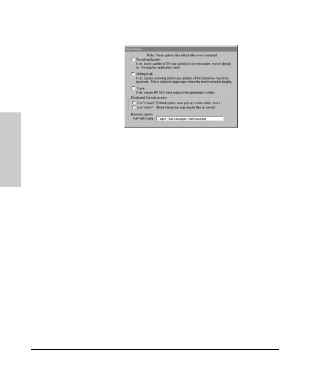
HP Hub & Switch
HP Hub & Switch Management Admin
HP Admin Parameters
Figure 10-3. OpenView Configuration Options
The options are described in more detail here.
Management Admin
ForceMapUpdates. If the attributes (name of icon, application name) of a
symbol are changed, for example, during an update, the symbol must be reregistered with OpenV iew for the change s to take effect. Sel ecting this opti on
will update the symbol the next time that the master copy of OpenView (ovw)
is run. If this option is not set, symbols that are already executable are not
updated with the new information.
10-12
NoMapWalk. When you start HP Hub & Switch Management, it can take a
long time to scan (“walk”) a large OpenVi ew map to get the information need ed
to provide full functionality . When the NoMapW alk option is selected, HP Hub
& Switch Management start up time is great ly d ecreased.
When NoMapWalk is enabled, the symbols of newly discovered devices wi ll
not be executable with a double-mouse-click. You must click on the device in
the OpenView map, then use the Monitor menu (select HP Hub/Bridge) to
display the device's Closeup View. You als o wil l lo se the ability to perform
batch security settings.
Trace. This option is provided to assist support personnel in tracking down
problems related to OpenView integration with HP Hub & Switch Management. Do not set this option unless you are told to do so by support personnel.
Page 85

HP Hub & Switch Management Admi n
HP Admin Parameter s
Distributed Console. HP Hub & Switch Management is started remotely
when you use Network Node Manager’s Distributed Console feature from a
client station. The program “ovexec” displays a pop-up window in which you
enter a password for the remote system. If you do not want this pop-up to be
displayed, that is, you do not wish to enter a password, select the “remsh”
option to start HP Hub & Switch Management remotely.
Note: If you select “remsh”, the name of your client machine must be
in the /etc/h os ts .eq ui v file or the $HOME/.rhosts file on the
remote system. Refer to these man pages for more information on these
files:
hosts.equiv
man
rhosts
man
Browser Lau nc h. Y ou can enter the full path name for the browser that will
launch when you click on a device that is manageable with a browser, for
example:
/opt/netscape/netscape
Management Admin
HP Hub & Switch
10-13
Page 86

HP Hub & Switch
HP Hub & Switch Management Admin
HP Admin Parameters
Management Admin
10-14
Page 87

Management for Non-Browserable Devic es
This chapter provides a summary of hub, bridge, and switch management
functions for devices that cannot be managed with the Web browser interface.
It includes the following topics:
■ About Closeup Views
■ Overview of Tool bar Functi ons
Use the online help for more information about specific device functions.
About Closeup Views
HP Hub & Switch Management provides direct acce ss to HP hub, bridge, and
switch management for devi ces that are no t manageab le with a W e b browser
through graphical co n trol panels, or Closeup Views. If you have switching
hubs, you can also use the Closeup View to create and modify segments in
your network.
11
Management for Non-
Browserable Devices
A Closeup View is an interactive, visual display of a devi ce. Y o u can use the
Closeup Vie w to obtai n devi ce status, and run Hub & Switch Management
command functions through push-button icons and menus. There is a Closeup
View for most HP managed devices.
There will be differences in the available function icons depending on the
device type. Icons for fun ctions that are not available fo r s ome de vices will
either not be selectable (grayed out) or will not appear. Also, menu options
launched from icons that are not available for some devices either will not
appear , or if they appear, they will not be selectable. For information on device
management funct ions for any particul ar device, refer to the o nline help in the
Closeup View .
For HP AdvanceStack hubs, Closeup Views are available for managing all hubs
on a Distributed Management Chain. Closeup Vi ews for chained hubs that are
without SNMP modules are accessed through the appropriate SNMP-based
hub's Closeup View . F unctions that are not avai lable for chained hubs will not
be selectable.
11-1
Page 88

Management for Non-Browserable Devices
About Closeup Views
Note
HP Hub & Switch Management now supports non-pulick community names
when displaying the Closup View. For configuring non-public community
names, refer to the HP OpenView Using Network Node Manager manual.
Displaying the Closeup View
You can display a Closeup View in several ways, including the following:
■ From an HP OpenVi ew map, use the l eft mouse button an d double-click
on a hub, bridge, or switch symbol.
■ On an HP OpenView map, select a hub, bridge, or switch symbol. Then
display the Monitor menu and select HP Hub/Switch.
■ From a Closeup View of an SNMP-based AdvanceStack hub, display the
list of chained hubs by clicking on the Chained Devices button. The list
displayed iden tifies each chained hub by MAC address an d hub type.
Select the MAC address for the desired hub.
■ Right-mouse-click on a device symbol and select Monitor HP Hub/
Switch.
Management for Non-
Browserable Devices
11-2
Page 89

Management for Non-Browserable Devic es
About Closeup Views
Figure 11-1. Switching Hub Closeup View
The number of Closeup Views that you can display at one time depends on
your free system resour ces available (such as avai lab le memory).
If the HP devic e can be m anaged with y our br owser, the menu option SNMP
Confi g ure HP Hu b/Swit ch will also display when you right-mouse-click on
a device symbol. Selecting this feature allow s you to conf igure community
names and authorized managers for the device. See the online help for
configuration instructions.
Closeup View Areas
The regions of the Closeup View are discussed below .
11-3
Management for Non-
Browserable Devices
Page 90

Management for Non-Browserable Devices
About Closeup Views
Title Bar
At the top of the Cl oseup View is a title b ar that displays the dev ice type and
its network address.
Message Bar
The Message Bar is al ong the botto m of th e Clo seup V iew. It is primari ly used
to identify , or describe the purpose of, various items in the view. Simply place
the cursor on an item and read the appropriate box in the Message Bar.
If a port is selected, the center box in the Message Bar identifies the selected
port (for example, “Port A9”).
Toolbar
The Toolbar contains buttons to perform Hub & Switch Management
commands and functions. If you place the cursor over a Toolbar button,
message bar text is displayed that id en tifies the command or function. (See
the online help for a description of the Toolbar icons.)
Activity Gauges
Management for Non-
Two linear bar charts, or “gauges”, are displayed o n most Closeup Views.
These gauges provide indications of LAN traffic sampled by the device. The
gauges are:
■ Activity%—Represents the total LAN activity viewed by all segments
attached to the device as a percent of the total bandwidth of the segments .
■ Collisions%—Shows the total collisions viewed by all segments attached
to the device as a percentage of total packets seen by these segments.
Browserable Devices
11-4
Hub LAN Ports
The Closeup View allows you to v iew each hub port and determine port status.
Port status can be determined by the port icon symbol and colors displayed.
Y ou can individually select any port on a Closeup View by clicking on the port
itself. The port numbe r will be displayed in the messag e bar. If you select a
port, you can perform management functions through the applicable Toolbar
button. (If passwords are used, you must be logged onto the hub to change a
port's configuration.)
Page 91

Management for Non-Browserable Devic es
Overview of Toolbar Functions
Overview of Toolbar Functions
HP Hub & Switch Management device functions in the Closeup Views allow
you to configure, monitor and manage HP hubs, bridges, and switches.
The following table summarizes the Toolbar menu functions in the Closeup
Views. For specific information about how to use a particular device function
or menu dialog box, click on the Help button in the dialog box.
Table 11-1. Summary of Toolbar Functions
Icon Toolbar Button Des cription
Device ID Displays identificatio n information for an HP hub,
bridge or switch. For example, you can determine
the device type, firmware vers ion, and MAC
address.
Graph Counters Displays the Graph Counters - Graph window for
graphing various counters and statis tical formulas
on a dev ice. The defau lt g raph i s the L AN Ac ti vit y%
statistics. If you position the cursor over the
graphing area and press the right mouse button, a
pop-up menu i s displayed. Select “Options” to
modify the counters and devices for graphing, and
to configure other graphing options .
Management for Non-
Browserable Devices
Port Statistics Display s gauges f or view ing statist ical coun ters f or
a segment and s elected port s on the segment.
• Hubs: gauges for LAN Acti vity, Error Packets,
and Broadca st Packets are displayed.
• Bridges : gauges for Broadcast Pack ets, Pac kets
Forwarded, Packets Filtered, and Error Packets
are displayed.
• Switches: gauges for LAN Activity, Packets
Forwarded, Packets Filtered, Broadcasts
Received, Collisions, and Errors Received are
displayed.
Port Statistics
Summary
Displays an information wi ndow that lists i mporta nt
statistics and counter values for each port on the
device. The displayed counters wil l differ
depending o n the devic e type ( for exa mple, 10Bas eT hub, 100VG hub, 10/100 swi tch, or bridg e).
11-5
Page 92

Management for Non-Browserable Devices
Overview of Toolbar Functions
Table 11-1. Summary of Toolbar Functions
Icon Toolbar Button Description
Logon Displays a Logon di alog box. If a hub, bridge or
Configuration Displays a tabbed dialog box for device
Diagnose Displays a pop-up menu list of device or network
switch has a p assword, you must first log on to it
before you can change configuration or security
feature s, or r un d iagnos ti c t ests . Lo gon pass words
are set up using the Conf iguratio n button ( select Set
Administration). If you forget a pas sw ord, you may
need to go to t he device t o c le ar th e p ass wor d ( see
your device m anuals).
configuration (The tabs displayed depend on the
device):
• Administration
•IP Config
• Thresholds
• Port Confi g uration
• Backup Link s
• Upload
• Download
• Monitor Port
•Address Table
• Wild Character Filter
• Spanning Tree
• Bridge Conf iguration
test func tions. The tests that can be performed
depend on the type of device.
Management for Non-
Browserable Devices
Security Displays a tabbed dialog box for configuring
security:
• Authorized Managers: The network
management s tati ons that can send and rec eive
SNMP requests for this device.
• Community Names: Names that are valid for
SNMP request s to th e devic e or stack of hubs. A
read and wri te level are specified for each
community name.
• Securit y Policy: Set global security for al l
devices of the same type on your network.
• Port Security: Configure Intruder Det e ction and
Eavesdrop P revention for each port.
• Intrusion Log: View security intrusions for a
device.
11-6
Page 93

Table 11-1. Summary of Toolbar Functions
Icon Toolbar Button Des cription
Management for Non-Browserable Devic es
Overview of Toolbar Functions
Enable Port Enables a selected hub port. If a password is
Disable Port Disables a selected hub port. If a password is
Logoff Displays a Logoff dialog box. If a hu b or bridge has
VLAN
Configuration
Properties D isplays a dialog box that allow s you to view or
assigne d to the hub, you must log on to the hub
before yo u can change the state of a port.
assigne d to the hub, you must log on to the hub
before yo u can change the state of a port.
a password, you can log off the device to prevent
configuration changes.
Displays the VLAN Configuration window.
change information about a selected VLAN or
segment:
• Port number
• Name of VLAN
• Connected status
• Enabled/Disabled st atus
• Active status
• Protocol type
Management for Non-
Browserable Devices
Large icons Displays ports as large icons.
Small icons Displays ports as small icons.
11-7
Page 94

Management for Non-Browserable Devices
Overview of Toolbar Functions
Table 11-1. Summary of Toolbar Functions
Icon Toolbar Button Description
List Lists all port icons in rows.
Details List inform ation with each port:
• Port number
• Segment to which the port belongs
• Connected status:
currently connected to a device
• Status: the po rt is enabled or dis abled.
Help Runs the Hub & Switch Management online help
system.
indi cates whether the port is
Management for Non-
Configuration Funct ions
The Configuration button displays a menu that allows you to perform configuration functions for the device. The menu items displ ayed depend on the type
of device.
See the online help for details about the Configuration menu items.
Browserable Devices
11-8
Setting the Configuration Parameters
When you select the Configuration icon, the Configuration tabbed dialog box
displays. By clicking on the appropriate tab, you can configure parameters for
your devices as well as performing software uploads to and downloads from
a configuration file. See the online help to obtain instructions for configuring
a specific function.
Page 95

Appendix A
Appendix A
Agent Firmware Versions
A
Appendix A contains the following topics:
■ Agent Firmware Versions
■ Preparing Network Devices
■ Globally Assign ed IP Network Addresses
■ Configuring IP Parameters
Agent Firmware Versions
HP Hub & Switch Management communicates with network devices using
SNMP (Simple Network Management Protocol).To access device features,
each network device must conta in a compatibl e version of agent softw are or
firmware.
Note: The latest firmware agents can be obtained from the Support
section of the HP networking W eb page. The URL is:
http://www.hp.com/go/procurve
Verifying Device Agent Versions
You can check the agent version on an HP device using one of the following
methods:
■ Use the device's console port interface (a non-network connection).
Y ou can connect a terminal or computer directly to the device or through
a modem. Refer to t he devi ce' s Installation and Reference Guide for use
of the device's RS-232 console port.
• For HP devices, you can use an ASCII terminal or computer wi th
VT 100 terminal emulation.
■ Use an available network application (a network connection).
Appendix A
A-1
Page 96

Appendix A
Preparing Network Devices
For HP devices, use an existing version of HP Hub & Switch Management
or other device management utility.
Update the device's softwar e or firmware to the current supported version.
Note: HP Hub & Switch Management may be able to discover devices
that have previo us versions of device agent firmware. However, the use
of some functions may be limited.
Preparing Networ k De vices
For HP Hub & Switch Management to communicate with devices on your
network, the network devices must:
■ have SNMP agent firmware th at is compatible with this version of HP Hub
& Switch Management.
■ for IP networks, have a unique IP network address.
Note: Hubs and bridges shipped prior to July 1992 must be upgraded.
Appendix A
Basic hub management feature s are avail able for chained Adva nceStack hubs
if they are connected to an SNMP-based hub of the same media type (10BaseT or 100VG) over a Distributed Management chain.
Device Network Addresses
On an IP network, each managed device must have an IP address. If you intend
to run HP Hub & Switch Management on an IP network, you must configure
the IP address for each device you want to manage.
IP addresses are normally co n figured when the device is installed. For
HP hubs, bridges, and switches, IP addresses are configured using the console
port interface. For more details on console port connection and available
commands, see the device 's Installation and Reference Guide.
Note: You can use HP Hub & Swi tch Managemen t to cha nge a n IP
address on a hub af ter it ha s be en as sig ne d, but not o n a sw itch o r a
A-2
Page 97

Appendix A
Configuring IP Parameters
bridge.
Globally Assigned IP Network Addresses
If you intend to connect your network to other networks that use globally
administered IP add resses, Hewlett-Packard strongly recommends that you
use IP addresses t hat have bee n assigned to you. There is a fo rmal proces s for
assigning unique IP addresses to networks worldwide. Contact one of the
following companies:
United States and countries not in Europe or
Asia/Pacific
Europe RIPE NCC
Asia/Pacific Attention: IN-ADDR.ARPA Registration
Network Solutions, Inc.
Attn: InterNIC Registration Service
505 Huntmar Park Drive
Herndon, VA 22070
Kruislaan 409NL-1098 SJ
Amsterdam
The Netherlands
Asia Pacific Network Inform ation Center
c/o Internet Initiative Japan, Inc.
Sanbancho Anne x Bldg. 1-4
Sanban-cho , Chiyoda-ku
Tokyo 102, Japan
For more information, refer to Internetworking with TCP/I P: Principl es,
Protocols and Architecture by Douglas E. Comer (Prentice-Hall, Inc.,
publisher).
1-703-7 42-4777
question s@internic.net
http://rs.internic.net
+31 20 592 506 5
ncc@ripe.net
http://ww w.ripe.net
domreg@apnic.net
http://www.apnic.net
Configuring IP Parameters
T o run HP Hub and Switch Management on an IP network, you must configure
the management station and all managed devices for IP.
A-3
Appendix A
Page 98

Appendix A
Configuring IP Parameters
The network management statio n is co nfigured for IP using the TCP/IP st ack
utilities. To configure a device for IP, you typically connect to the device's
console port and use the cons ol e port in terface. (Refer to the device's installation manual for more information.)
Before you configure the network management station and manageable
devices for IP, make a list of all the device s on the network and what their IP
addresses will be.
Note: Make sure that every device has a unique IP address. Make sure
that all devices on a given IP network number have the same subnet
mask.
The IP configuration parameters are described below.
IP Address . The IP address of the hub, bridge, or switch is written in the
format X.X.X. X, where each X is a d ecimal nu mber betwe en 1 and 254. Every
IP address on a network must be unique.
The default val u e, 0.0.0.0, dis ab les IP communications. Use the default value
only if you are not going to manage the device with HP Hub & Switch
Management and you want to disable IP communicatio n s for that device.
Appendix A
Subnet Mask. The bit mask defines which portion of the IP address is the
subnet address and is written in the format X.X.X.X. The default value is
automatically generated and depends on the class of IP address that you
entered. See your network administrator for the subnet mask address. All
devices on a given IP network number must use the same subnet mask
address.
Primary Default Router . The routing IP address o f the nearest r outer in
your network. The default is 0.0.0.0.
Backup Default Route r. Th e IP address of th e router t o use when the
primary default router is inaccessible. The default value is 0.0.0.0. If there is
no backup router and no primary default router, use the default.
Time To Live . The number of IP routers a packet is allowed to cross before
the packet is di scarded. The d efault value is 32. Increa se thi s value if t he hub,
bridge, or switch is managed from a network management station that is more
than 32 routers away. The maximum allowable value is 255.
Note: For selected devices, such as the HP J2980A AdvanceStack 10/
100 LAN Switc h-1 6 , you mus t preco n fi gure the SN MP communi ty
A-4
Page 99

Appendix A
Configuring IP Parameters
name “public” on the device to allow the device to be discover ed and
managed by HP Hub and Switch Management. Typically, the
community name on HP hubs and bridges will automatically default to
“public”.
T o confi gure a device for IP network s, use the devi ce's console port inter face.
Refer to t he d evice's Installation and Reference Guide fo r use of the de vice's
RS-232 console port.
Note: For HP hubs, HP Hub & Switch Management can be used to
change IP addresses afte r they have been initially assigned during
installation.
Network Bootp Server
HP EtherTwist Hub Plus/24S and HP AdvanceStack 10Base-T hubs (with
SNMP modules installed) support the use of Bootp (Bootstrap Protocol) to
automatically retrieve their IP config uration from a server on the network. A
device's IP configuration must be configured in a file on the Bootp server.
When the device is powered on, Bootp is used to automatically download the
IP configuration to the device.
■ Each device that supports Bootp must have Bootp enabled to retrieve its
IP configuration from the server. The factory default setting is for Bootp
operation to be enabled. You can enable or disable Bootp operation
through the device's console port, or from a network management application (such as HP Hub & Switch Management).
■ For more information on IP configuration using Bootp, refer to your
device's Installation and Reference Guide.
A-5
Appendix A
Page 100

Appendix A
Configuring IP Parameters
Appendix A
A-6
 Loading...