

Page 1

HPE OfficeConnect 1920S Switch Series
Quick Start Guide
*5200-2869*
Part Number: 5200-2869
Published: December, 2016
Edition: 1
Page 2

Notices
The information contained herein is subject to change without notice. The only warranties for Hewlett
Packard Enterprise products and services are set forth in the express warranty statements accompanying
such products and services. Nothing herein should be construed as constituting an additional warranty.
Hewlett Packard Enterprise shall not be liable for technical or editorial errors or omissions contained
herein.
Confidential computer software. Valid license from Hewlett Packard Enterprise required for possession,
use, or copying. Consistent with FAR 12.211 and 12.212, Commercial Computer Software, Computer
Software Documentation, and Technical Data for Commercial Items are licensed to the U.S. Government
under vendor's standard commercial license.
Links to third-party websites take you outside the Hewlett Packard Enterprise website. Hewlett Packard
Enterprise has no control over and is not responsible for information outside the Hewlett Packard
Enterprise website.
Applicable products
HPE OfficeConnect 1920S 8G Switch JL380A
HPE OfficeConnect 1920S 24G 2SFP Switch JL381A
HPE OfficeConnect 1920S 48G 4SFP Switch JL382A
HPE OfficeConnect 1920S 8G PPoE+ 65W Switch JL383A
HPE OfficeConnect 1920S 24G 2SFP PPoE+ 185W Switch JL384A
HPE OfficeConnect 1920S 24G 2SFP PoE+ 370W Switch JL385A
HPE OfficeConnect 1920S 48G 4SFP PPoE+ 370W Switch JL386A
Page 3

Contents
HPE OfficeConnect 1920S Switch Series............................................. 4
Warranty and regulatory information..................................................10
Example: Initial Switch Configuration............................................................................................7
SFP Installation Notes.................................................................................................................. 8
Safety Precautions......................................................................................................................10
Installation Precautions.................................................................................................... 10
Regulatory and Safety Information............................................................................................. 10
1920S Switch Series Information — Regulatory and Safety............................................ 11
Documentation feedback............................................................................................................ 16
Contents 3
Page 4
HPE OfficeConnect 1920S Switch Series
The switch drawings in this document are for illustration only and may not match your particular
switch model.
For more detailed instructions and information to set up your switch, view or download the Installation and
Getting Started Guide for your switch at
NOTE:
The HPE OfficeConnect 1920S Switch Series 8-port, 24-port, and 48-port non-PoE+ models have a
fan-free design, making them quiet for office deployments. A warmer than normal enclosure is a
standard state of operation for a fan-free switch.
Although the top of the switch enclosure may feel warm to the touch, it has no effect on functionality
or performance of the product.
1. Unpack and check included parts. • Documentation kit
http://www.hpe.com/support/hpesc.
• Switch
• Accessory kit (installation hardware)
• AC power cord for HPE 1920S-24G,
1920S-24G-PPoE+, 1920S-24G-PoE+,
1920S-48G, and 1920S-48G-PPoE switch
models or DC external power adapter for
1920S-8G and 1920S-8G-PPoE+ switch models
2. Prepare for installation. To avoid personal injury or product damage, review the Safety
Precautions.
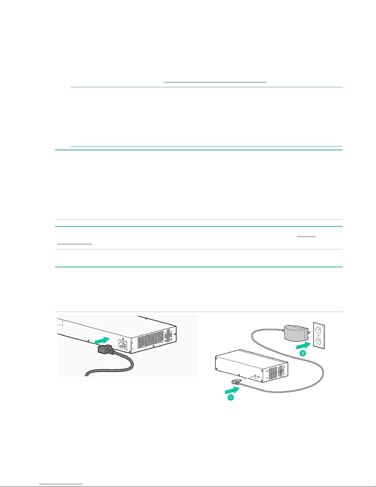
3. Power-on and verify that Self-Test completes normally.
For the 1920S-24G, 1920S-24G-PPoE+, 1920S-24G-PoE+, 1920S-48G, and 1920S-48G-PoE+
switches, first connect the power cord to the power connector at the back of the switch. Then, connect
the other end of the power cord into an electrical outlet. For the 1920S-8G and 1920S-8G-PoE+
switches, connect the AC/DC adapter power cord to the power connector at the back of the switch. Then
plug the AC/DC power adapter into an electrical outlet.
4. Mount the switch.
4 HPE OfficeConnect 1920S Switch Series
Page 5
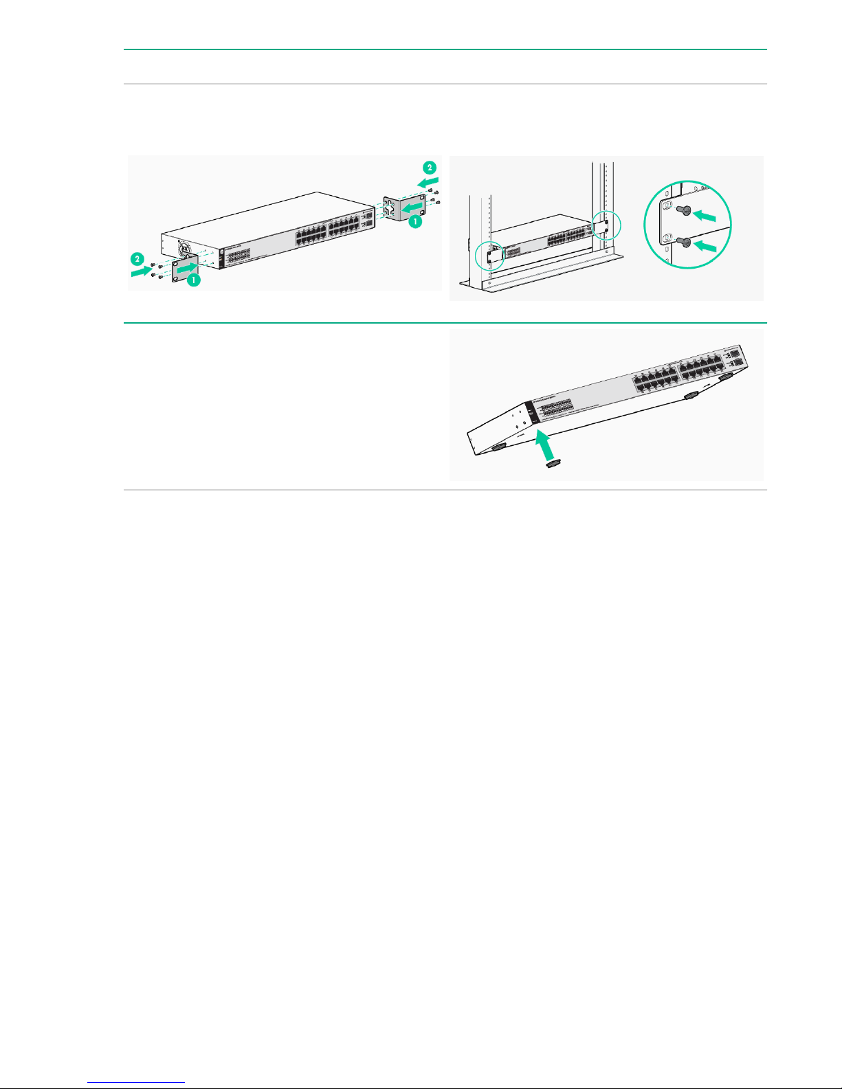
Unplug the AC or DC power from the switch before mounting it.
Rack Mounting: To attach the accessory kit brackets to the switch, use the eight 8-mm M4 screws and
a #1 Phillips (cross-head) screwdriver. Then secure the brackets to the rack by using the four number
12-24 screws.
Table or Desktop Mounting: Attach the four selfadhesive pads (included in the accessory kit) to the
bottom corners of the switch.
HPE OfficeConnect 1920S Switch Series 5
Page 6

Wall or Under-table Mounting: To mount the
1920S-24G, 1920S-24G-PPoE+, 1920S-24G-PoE
+, 1920S-48G, and 1920S-48G-PPoE+ switches:
• First attach the mounting brackets to the switch
by using the included 8-mm M4 screws with a
#1 Phillips (cross-head) screwdriver.
• Then attach the switch to the wall or wood
surface with two 5/8-inch number 12 wood
screws (not included).
To mount the 1920S-8G and 1920S-8G-PPoE+
switches:
• First, mark the position for the mounting screws.
The hole-to-hole distance is 3.54 inch (90-mm).
• Then, use a #1 Phillips (cross-head)
screwdriver and two of the included 20-mm 4
tap screws. Set the screw heads approximately
2 mm away from the mounting surface to allow
the switch to slide on to the screws. Wall
anchors are included in the accessory kit for
use with plastered brick or concrete walls.
• For an under-table mounting, a third 20-mm M4
tap screw can be placed against one side of the
switch to secure it in place.
IMPORTANT:
Wall-mount the switch with network ports
facing up or down (away from or toward the
floor). Do not wall-mount the switch with the
ventilation holes facing up or down. (See
Installation Precautions.)
5. Power on the switch.
Follow the same procedures as in step 3.
6. Configure the switch for operation on your network (minimal configuration).
6 HPE OfficeConnect 1920S Switch Series
Page 7

Connect a PC directly to the switch with a standard
Ethernet cable. Before you connect the switch to
the network, configure the IP Address and Subnet
Mask for the PC. The IP addressing allows the
switch to communicate with the switch through the
Web browser on your PC. The switch factory
default settings include the following values:
Parameter Factory Default Setting
User name admin
Password <blank>
IP address 192.168.1.1
Subnet Mask 255.255.255.0
Default gateway not set
To enable the switch to operate in your network,
modify the IP configuration as needed. See
Example: Initial Switch Configuration.
7. Connect the network cables.
NOTE:
For transceiver connections, install and use
only HPE SFP transceivers supported by the
switch. See SFP Installation Notes.
Example: Initial Switch Configuration
Procedure
1. Reconfigure the PC’s IP address and Subnet Mask so that it can communicate with the switch.
a. Click Start > Control Panel. Type adapter in the search box, and then click View network
connections.
b. Select and right-click Local Area Connection, then click Properties.
c. Click the Networking tab. Select Internet Protocol Version 4 (TCP/IPv4) under This connection
uses the following items, and then click Properties.
NOTE:
Be sure to record all your PC’s current IP settings to be able to restore them later.
d. On the General tab, click Use the following IP address.
e. For IP address, enter an IP address in the same range as the switch’s default IP address. For
example, enter 192.168.1.12.
Example: Initial Switch Configuration 7
Page 8

f. For Subnet mask, enter 255.255.255.0, then click OK.
g. Click Close (or OK) to close the Local Area Connection Properties screen.
2. Open your Web browser on the PC, and enter the switch factory-default address, http://192.168.1.1,
to access the switch’s Web interface.
3. Click Log on to log on to the switch (by default, there is no password).
4. Click Network Setup > Get Connected and configure IP network settings on the switch for operation
on your network.
IMPORTANT:
When the switch starts, it attempts to obtain an IP address from a DHCP server. If the DHCP
server is unreachable, the switch falls back to a static IP address, that is, 192.168.1.1. If a DHCP
address is obtained then you must determine the IP address assigned to the switch. To
determine the IP address, access your DHCP server files or use LLDP (Link Layer Discovery
Protocol) commands on a connected device (such as another switch). For more information on
Initial Configuration, see the HPE OfficeConnect 1920S Installation and Getting Started Guide
available at http://www.hpe.com/support/manuals
.
5. Click Apply on the browser configuration screen to save your settings to retain them when the switch
is rebooted.
You are done with initial switch configuration. Disconnect the LAN cable from your PC and connect the
switch in to the network.
Be sure to return your PC to its original network settings before connecting to your network.
SFP Installation Notes
NOTE:
When selecting a fiber SFP device, make sure it can function at a maximum temperature that is not
less than the recommended maximum operational temperature of the product. Use only an
approved Laser Class 1 SFP transceiver.
NOTE:
To ensure proper operation of your switch, use only the HPE Aruba SFP transceivers supported by
your switch.
Use only supported HPE Aruba SFP transceivers. Non-HPE Aruba SFP transceivers are not
supported. Use of supported HPE Aruba products ensures that your network maintains optimal
performance and reliability. If you require additional transceivers, contact an HPE Aruba sales
representative or an authorized reseller. The following resources can help you to find transceiver support
information for your switch model:
• See the HPE ArubaOS-Switch Transceiver Guide in the Hewlett Packard Enterprise Information
Library at http://www.hpe.com/networking/ResourceCenter.
• See the supported transceivers information in the QuickSpecs for your switch model at http://
www.hpe.com/networking/products, along with minimum software versions to support the listed
transceivers:
1. Select Switches.
2. Select Aruba Switches.
3. Select a switch model.
4. Select Product Details.
5. Select an option under QuickSpecs.
8 SFP Installation Notes
Page 9

Hot Swapping SFP transceivers. Supported SFP transceivers that you can install in your Hewlett
Packard Enterprise OfficeConnect switch can be “hot swapped”. "Hot swapping" means supported
transceivers can be removed and installed while the switch is receiving power. Disconnect the network
cables from the SFP transceivers before hot-swapping them.
When you replace an SFP transceiver with another of a different type, the switch may retain selected
port-specific configuration settings that were configured for the replaced unit. Be sure to validate or
reconfigure port settings as required.
SFP Connections to Devices with Fixed Speed/Duplex Configurations. When connecting a device to
your switch port that contains an SFP transceiver, the speed and duplex settings of the switch port and
the connected device must match. If the settings do not match, the device may not link properly—you
may not get a link. For some older network devices, including some older Hewlett Packard Enterprise
devices, the default speed/duplex settings may be predefined. (For example, a setting might be 1000
Mbps/Full Duplex.) There may also be other settings that differ from the default configuration of your
switch port. Because of these default speed/duplex considerations, make sure that devices connected to
your SFP ports are properly configured. At a minimum, make sure the configurations match.
HPE OfficeConnect 1920S Switch Series 9
Page 10

Warranty and regulatory information
Safety Precautions
Installation Precautions
WARNING:
• The rack or cabinet should be adequately secured to prevent it from becoming unstable, tilting,
or falling. Devices installed in a rack or cabinet should be mounted as low as possible, with the
heaviest devices at the bottom and progressively lighter devices above.
• Do not wall-mount any switch without checking for restrictions in the Installation and Getting
Started Guide at http://www.hpe.com/networking/ResourceCenter. Wall-mount the switch
with network ports facing up or down (away from or toward the floor). Do not wall-mount the
switch with the ventilation holes facing up or down.
CAUTION:
• Ensure the power source circuits are properly grounded, then use the power cord supplied with
the switch to connect to the AC power source.
• If your installation requires a different power cord than the one supplied with the switch and/or
power supply, be sure the cord is adequately sized for the switch’s current requirements. In
addition, be sure to use a power cord displaying the mark of the safety agency that defines the
regulations for power cords in your country/region. The mark is your assurance that the power
cord can be used safely with the switch and power supply.
• When installing the switch, the AC outlet should be near the switch and should be easily
accessible in case the switch must be powered off.
• Ensure that the switch does not overload the power circuits, wiring, and over-current protection.
To determine the possibility of overloading the supply circuits, add together the ampere ratings of
all devices installed on the same circuit as the switch, and compare the total with the rating limit
for the circuit. The maximum ampere ratings are usually printed on the devices near the AC
power connectors.
• Do not install the switch in an environment where the operating ambient temperature exceeds its
specification.
• Ensure that the air flow around the switch is not restricted. Leave at least 7.6 cm (3 inches) for
cooling.
Regulatory and Safety Information
For important safety, environmental, and regulatory information, see Safety and Compliance Information
for Server, Storage, Power, Networking, and Rack Products, available at http://www.hpe.com/support/
Safety-Compliance-EnterpriseProducts.
10 Warranty and regulatory information
Page 11

1920S Switch Series Information — Regulatory and Safety
1920S-8G
Switch
(JL380A)
Electrical: For power,
requires one
of the
following:
• External
power
AC voltage: 100-127 /
Maximum
current:
Frequency
range:
adapter
module.
• or, PoE
PD
connectio
ns to Port
1
1920S-24G
Switch
(JL381A)
For power,
requires a
power cord
connection
from an AC
power source
200-240
0.5 / 0.3 A 0.8 / 0.5 A 2.6 / 1.3 A 5.1 / 2.6 A
50/60 Hz 50/60 Hz 50/60 Hz 50/60 Hz
1920S-48G
Switch
(JL382A)
For power,
requires a
power cord
connection
from an AC
power source
100-127 /
200-240
1920S-8GPPoE
+ (65W)
Switch
(JL383A)
For power,
external
power
adapter
module is
required.
1920S-24GPPoE
+ (185W)
Switch
(JL384A)
For power,
requires a
power cord
connection
from an AC
power source
100-127 /
200-240
1920S-24GPOE
+ (370W)
Switch
(JL385A)
1920S-48GPPoE
+ (370W)
Switch
(JL386A)
For power,
requires a
power cord
connection
from an AC
power source
100-127 /
200-240
1920S-8G, 1920S-24G, 1920S-48G, 1920S-8G-PPoE
+ (65W), 1920S-24G-PPoE+ (185W), 1920S-24G-PoE
+ (370W), and 1920S-48G-PPoE+ (370W) Switches
Environmental
:
Operating Temperature: 0°C to 40°C (32°F to 104°F)
Relative humidity: 15% to 95% at 40°C (104°F), non-condensing
Non-Operating Temperature: -40°C to 70°C (-40°F to 158°F)
Non-Operating Relative humidity: 15% to 90% at 65°C (149°F), non-condensing
Maximum Operating Altitude: Up to 3 km (10,000 ft)The operating maximum altitude
should not exceed that of any accessory being connected
to the switch.
Table Continued
1920S Switch Series Information — Regulatory and Safety 11
Page 12

1920S-8G, 1920S-24G, 1920S-48G, 1920S-8G-PPoE
+ (65W), 1920S-24G-PPoE+ (185W), 1920S-24G-PoE
+ (370W), and 1920S-48G-PPoE+ (370W) Switches
Acoustic
Safety
NOTE:
Use only supported HPE SFP transceivers with your switch.
When selecting a fiber SFP device, make sure it can function at a temperature that is not less than
the recommended maximum operational temperature of the product. Use only an approved Laser
Class 1 SFP transceiver.
1920S-8G Switch, 1920S-8G-PPoE+ (65W) Switch,
1920S-24G Switch, and 1920S-48G Switch have no fan,
0 dB
; 1920S-24G-PPoE+ (185W) Switch, 1920S-24G-PoE
+ (370W) Switch, and 1920S-48G-PPoE+ (370W) Switch
have fans, 45 dB
CSA22.2 No. 60950-1; EN60950-1/IEC60950-1;
UL60950-1EN 60825-1 / IEC 60825-1 Class 1; Class 1
Laser Products / Laser Klasse 1
1920S-8G External Power Adapter and Power Cords:
Universal inline power adapter
(5066-55631) specifications:
• AC Input Voltage: 100–240 V
• Maximum AC Input Current:
0.4 A
• AC Input Frequency Range:
50/60 Hz
• DC Output Voltage: 12 ± 10%
V
• Maximum DC Output Power:
15 W
• Maximum DC Output Current:
1.25 A
AC power cord:
8121-0870 Australia/New Zealand
8121-0664 Thailand
8120-8373 China
8121-0702 India
8120-6314 Israel
8120-6316 Japan
8120-6317 South Africa
12 1920S-8G External Power Adapter and Power Cords:
8120-8441 South Korea
8121-0963 Taiwan
8120-8699 United Kingdom/Hong Kong/
Singapore/Malaysia
8121-1081 Brazil
8121-8367 Argentina
8121-0514 Chile
Table Continued
Page 13

Wall plug-in power adapter
Power adapter:
specifications:
• AC Input Voltage: 100–240 V
• Maximum AC Input Current:
0.4 A
5066-5562
5184-5864 Continental Europe/Denmark/
2
• AC Input Frequency Range:
50/60 Hz
• DC Output Voltage: 12 ± 10%
V
• Maximum DC Output Power:
13 W
• Maximum DC Output Current:
1.085 A
1
Complies with DoE Level VI.
2
Complies with DoE Level VI.
1920S-8G-PPoE+ External Power Adapter and Power Cords:
(AC power cords are not used)
United States/Canada/Mexico
Norway/Sweden/Switzerland/
Israel/ Vietnam/Indonesia
Universal inline power adapter
(5066-55691) specifications:
• AC Input Voltage: 100–240 V
• Maximum AC Input Current:
1.4 A
• AC Input Frequency Range:
50/60 Hz
• DC Output Voltage: 54+/- 1.5
V
• Maximum DC Output Power:
90 W
• Maximum DC Output Current:
1.67 A
AC power cord:
8121-0837 Australia/New Zealand
8121-0943 China
8121-0731 Continental Europe
8121-0733 Denmark
8121-0564 India
8121-1004 Israel
8121-1143 Japan
8121-0737 South Africa
8121-0731 South Korea
8121-0738 Switzerland
8121-0964 Taiwan
8121-0734 Thailand
8121-0739 United Kingdom/Hong Kong/
Singapore/Malaysia
8121-1141 United States/Canada/Mexico
8121-1071 Brazil
Table Continued
1920S-8G-PPoE+ External Power Adapter and Power Cords: 13
Page 14

8121-0729 Argentina
8121-0735 Chile
1
Complies with DoE Level VI.
1920S-24G, 1920S-24G-PPoE+, 1920S-48G Power Cords
AC power cord:
8121-0837 Australia/New Zealand
8121-0943 China
8121-0731 Continental Europe
8121-0733 Denmark
8121-0564 India
8121-1004 Israel
8121-1143 Japan
8121-0737 South Africa
8121-0731 South Korea
8121-0738 Switzerland
8121-0964 Taiwan
8121-0734 Thailand
8121-0739 United Kingdom/Hong Kong/Singapore/Malaysia
8121-1141 United States/Canada/Mexico
8121-1071 Brazil
8121-0729 Argentina
8121-0735 Chile
1920S-48G-PPoE+ and 1920S-24G-PoE+ Power Cords
AC power cord:
8121-1476 Australia/New Zealand
8121-1484 China
8121-1479 Continental Europe
14 1920S-24G, 1920S-24G-PPoE+, 1920S-48G Power Cords
Table Continued
Page 15

AC power cord:
8121-1486 Denmark
8121-1483 India
8121-1478 Israel
8121-1482 Japan
8121-1483 South Africa
8121-1479 South Korea
8121-1480 Switzerland
8121-1511 Taiwan
8121-1485 Thailand
8121-1475 United Kingdom/Hong Kong/Singapore/Malaysia
8121-0914 United States/Canada/Mexico
8121-1265 Brazil
8121-1481 Argentina
8121-1477 Chile
1920S-8G Switch (JL380A), 1920S-24G Switch (JL381A), 1920S-48G Switch (JL382A), 1920S-8GPPoE+ (65W) Switch (JL383A), 1920S-24G-PPoE+ (185W) Switch (JL384A), 1920S-24G-PoE
+ (370W) Switch (JL385A), and 1920S-48G-PPoE+ (370W) Switch (JL386A)
Russia/Belarus/Kazakhstan/CEE Safety:
For manufacturer and local representative information, see Safety and Compliance Information for Server,
Storage, Power, Networking, and Rack Products at http://www.hpe.com/support/Safety-Compliance-
EnterpriseProducts.
China Altitude Warning:
Warranty and regulatory information 15
Page 16

Japan Power Cord Warning:
Documentation feedback
Hewlett Packard Enterprise is committed to providing documentation that meets your needs. To help us
improve the documentation, send any errors, suggestions, or comments to Documentation Feedback
docsfeedback@hpe.com). When submitting your feedback, include the document title, part number,
(
edition, and publication date located on the front cover of the document. For online help content, include
the product name, product version, help edition, and publication date located on the legal notices page.
16 Documentation feedback
 Loading...