

1-174
H
Dome Packages
The HLMP-6XXX Series dome
lamps for use as indicators use
a tinted, diffused lens to provide
a wide viewing angle with a
high on-off contrast ratio. High
brightness lamps use an
untinted, nondiffused lens to
provide a high luminous
intensity within a narrow
radiation pattern.
Arrays
The HLMP-66XX Series
subminiature lamp arrays are
available in lengths of 3 to 8
elements per array. The
luminous intensity is matched
within an array to assure a 2.1
to 1.0 ratio.
Resistor Lamps
The HLMP-6XXX Series 5 volt
subminiature lamps with built
in current limiting resistors are
for use in applications where
space is at a premium.
Lead Configurations
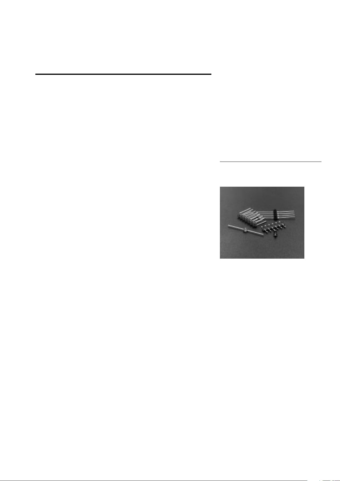
All of these devices are made by
encapsulating LED chips on
axial lead frames to form molded
epoxy subminiature lamp
packages. A variety of package
configuration options is available. These include special
Features
• Subminiature Flat Top
Package
Ideal for Backlighting and
Light Piping Applications
• Subminiature Dome
Package
Diffused Dome for Wide
Viewing Angle
Nondiffused Dome for High
Brightness
• Arrays
• TTL and LSTTL
Compatible 5 Volt Resistor
Lamps
• Available in Six Colors
• Ideal for Space Limited
Applications
• Axial Leads
• Available with Lead
Configurations for Surface
Mount and Through Hole
PC Board Mounting
Description
Flat Top Package
The HLMP-PXXX Series flat top
lamps use an untinted, nondiffused, truncated lens to
provide a wide radiation pattern
that is necessary for use in
backlighting applications. The
flat top lamps are also ideal for
use as emitters in light pipe
applications.
Subminiature LED Lamps
Technical Data
surface mount lead configurations, gull wing, yoke lead or Zbend. Right angle lead bends at
2.54 mm (0.100 inch) and
5.08 mm (0.200 inch) center
spacing are available for
through hole mounting. For
more information refer to
Standard SMT and Through
Hole Lead Bend Options for
Subminiature LED Lamps data
sheet.
HLMP-PXXX Series
HLMP-QXXX Series
HLMP-6XXX Series
HLMP-70XX Series
5964-9350E
1-175
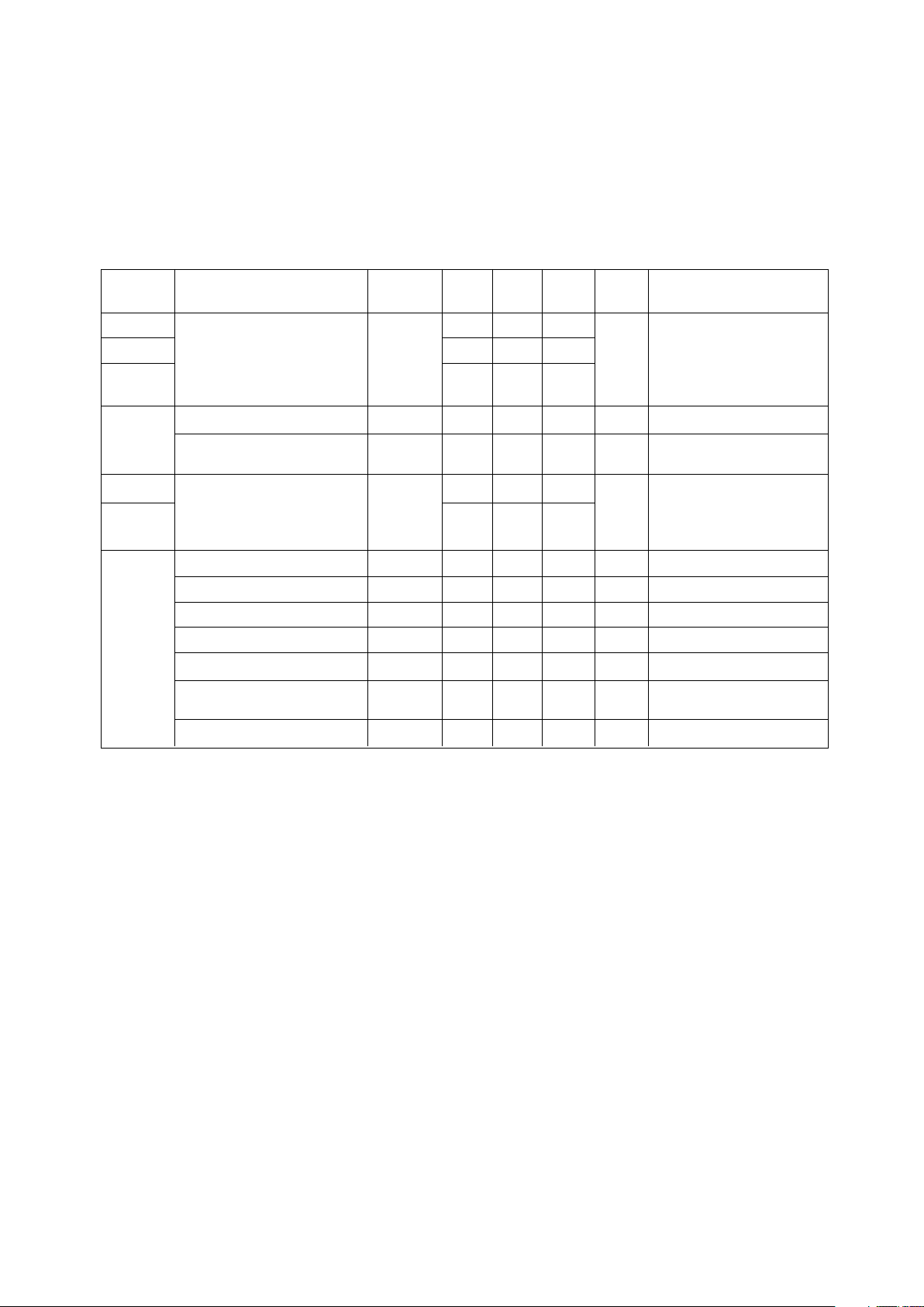
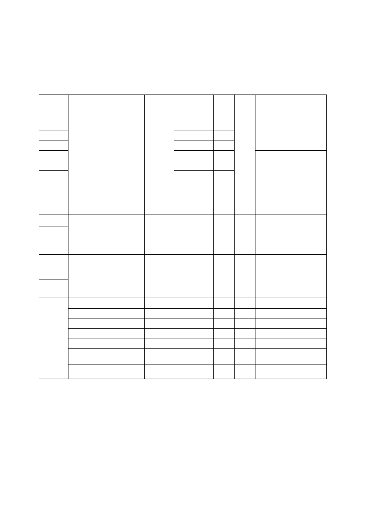
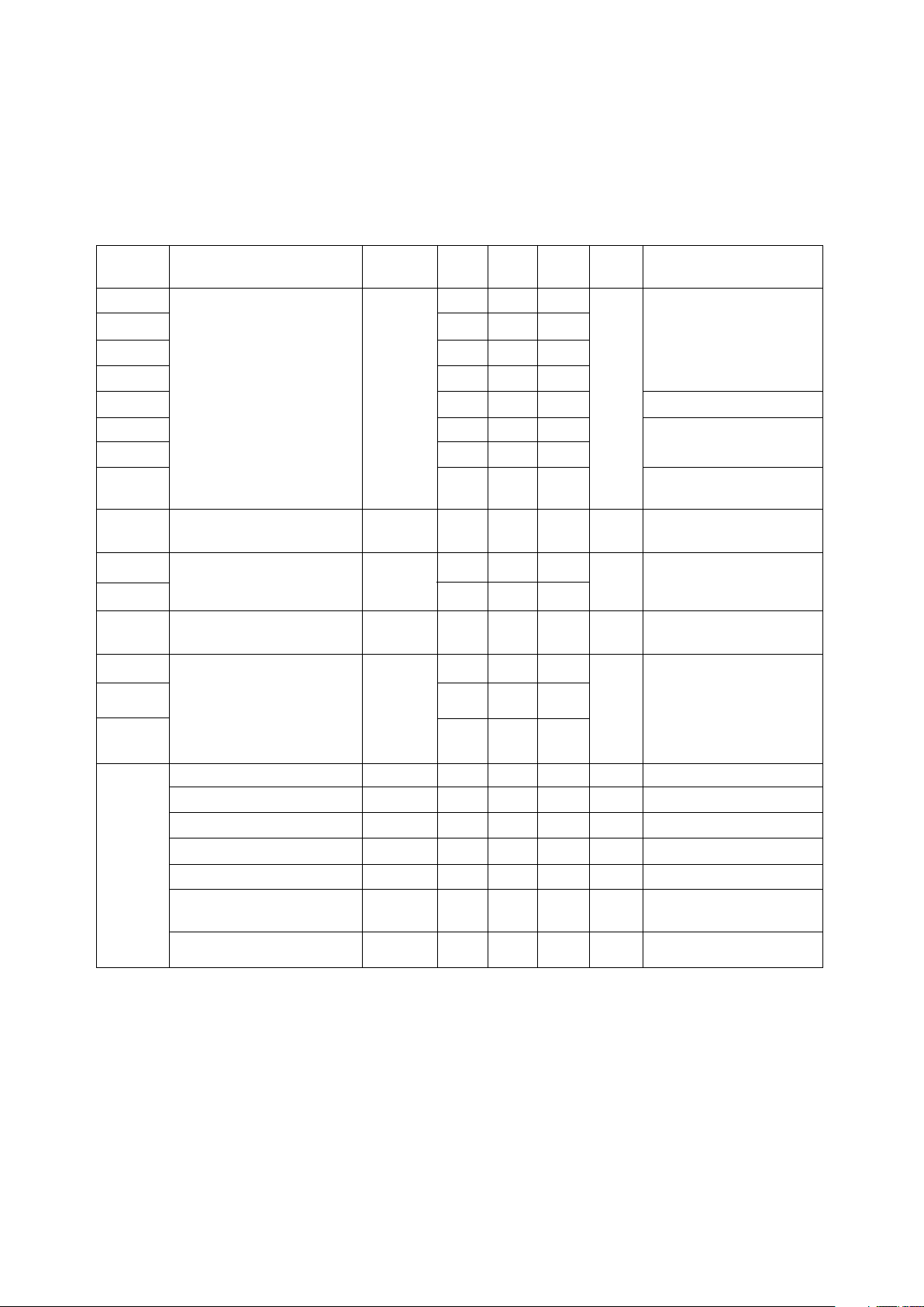
DH AS High High Device
Standard AlGaAs Efficiency Perf. Emerald Outline
Red Red Red Orange Yellow Green Green Device Description
[1]
Drawing
P105 P205 P405 P305 P505 P605 Untinted, Nondiffused, A
Flat Top
P102 P202 P402 P302 P502 Untinted, Diffused, B
Flat Top
6000/6001 Q101 6300 Q400 6400 6500 Q600 Tinted, Diffused
Q105 6305 6405 6505 Untinted, Nondiffused,
High Brightness
Q150 7000 7019 7040 Tinted, Diffused, Low B
Current
Q155 Nondiffused, Low
Current
6600 6700 6800 Tinted, Diffused,
Resistor, 5 V, 10 mA
6620 6720 6820 Diffused, Resistor, 5 V,
4 mA
6203 6653 6753 6853 3 Element Matched
6204 6654 6754 6854 4 Element
6205 6655 6755 6855 5 Element C
6206 6656 6756 6856 6 Element
6208 6658 6758 6858 8 Element
Device Selection Guide
Part Number: HLMP-XXXX
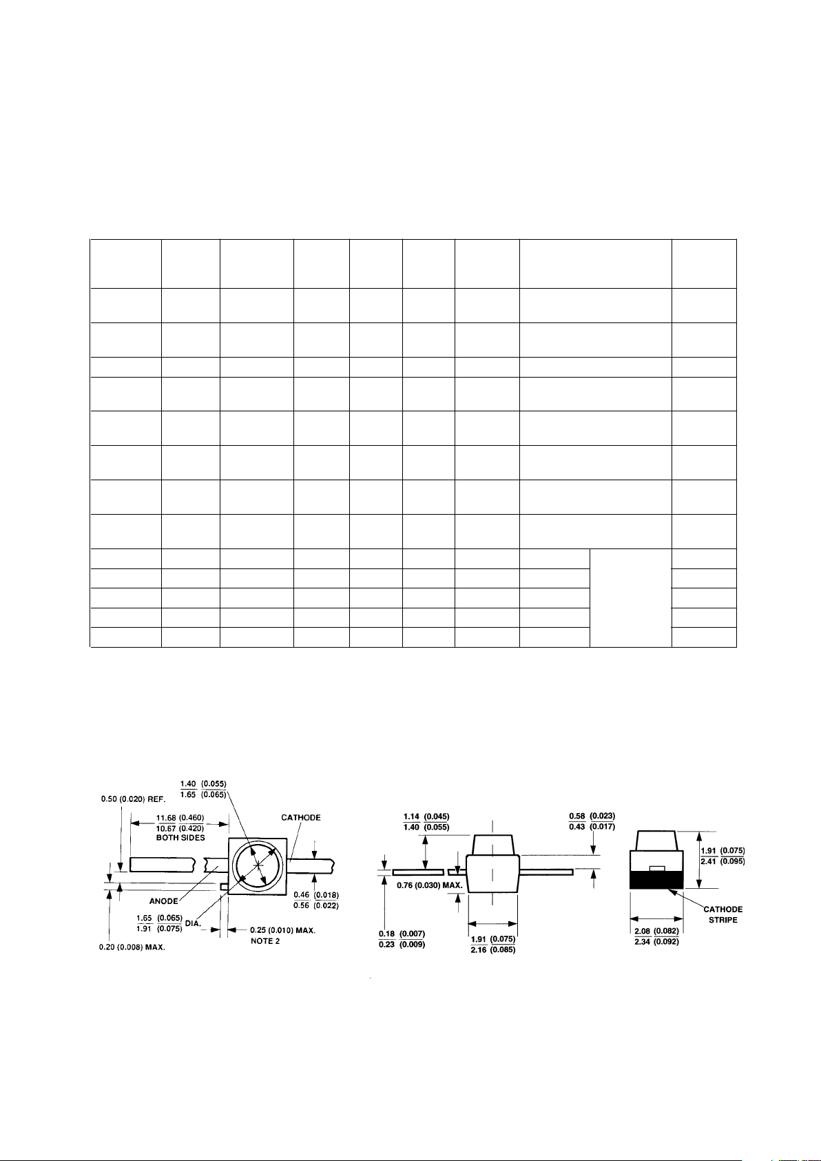
Package Dimensions
(A) Flat Top Lamps
NOTES:
1. ALL DIMENSIONS ARE IN MILLIMETERS (INCHES).
2. PROTRUDING SUPPORT TAB IS CONNECTED TO CATHODE LEAD.
*Refer to Figure 1 for design concerns.
Array,
Tinted,
Diffused
1-176
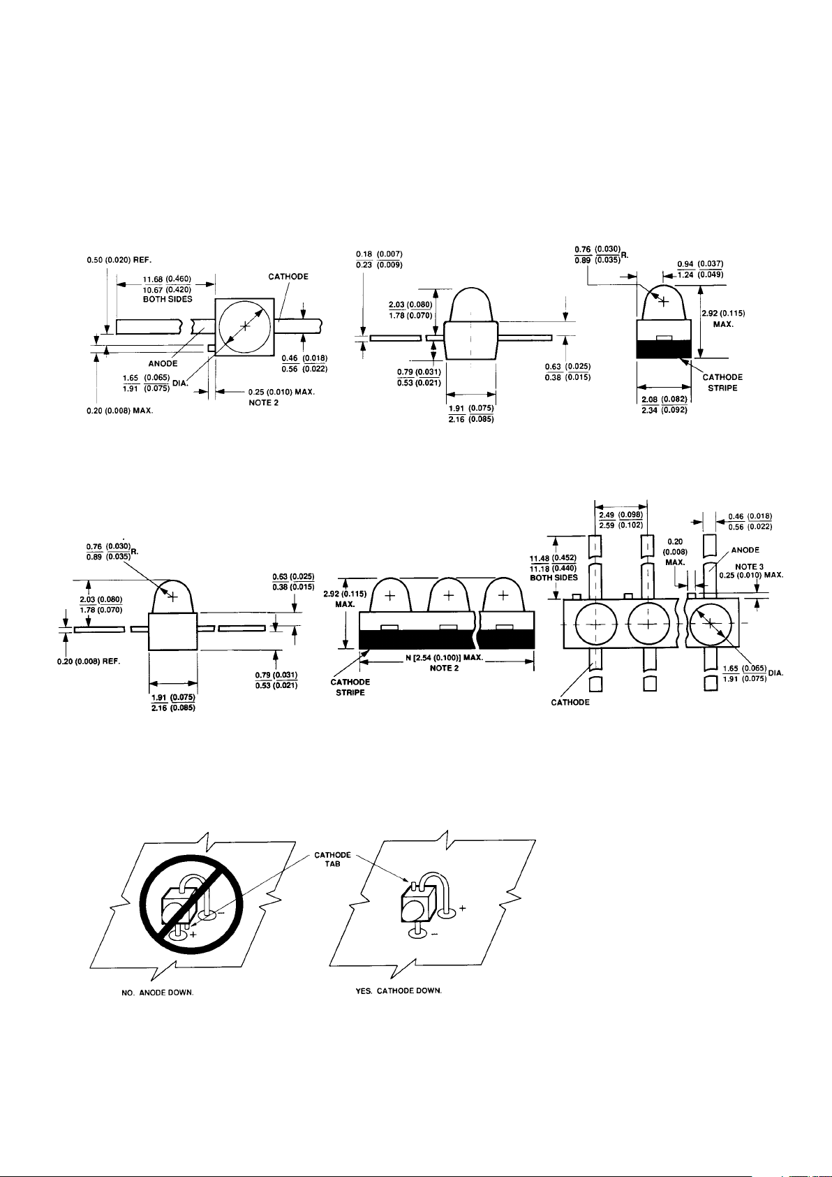
Package Dimensions (cont.)
(B) Diffused and Nondiffused
Figure 1. Proper Right Angle Mounting to a PC Board to Prevent Protruding Cathode Tab from Shorting to Anode
Connection.
NOTES:
1. ALL DIMENSIONS ARE IN MILLIMETERS (INCHES).
2. PROTRUDING SUPPORT TAB IS CONNECTED TO CATHODE LEAD.
*Refer to Figure 1 for design concerns.
(C) Arrays
NOTES:
1. ALL DIMENSIONS ARE IN MILLIMETERS (INCHES).
2. PROTRUDING SUPPORT TAB IS CONNECTED TO CATHODE LEAD.
1-177
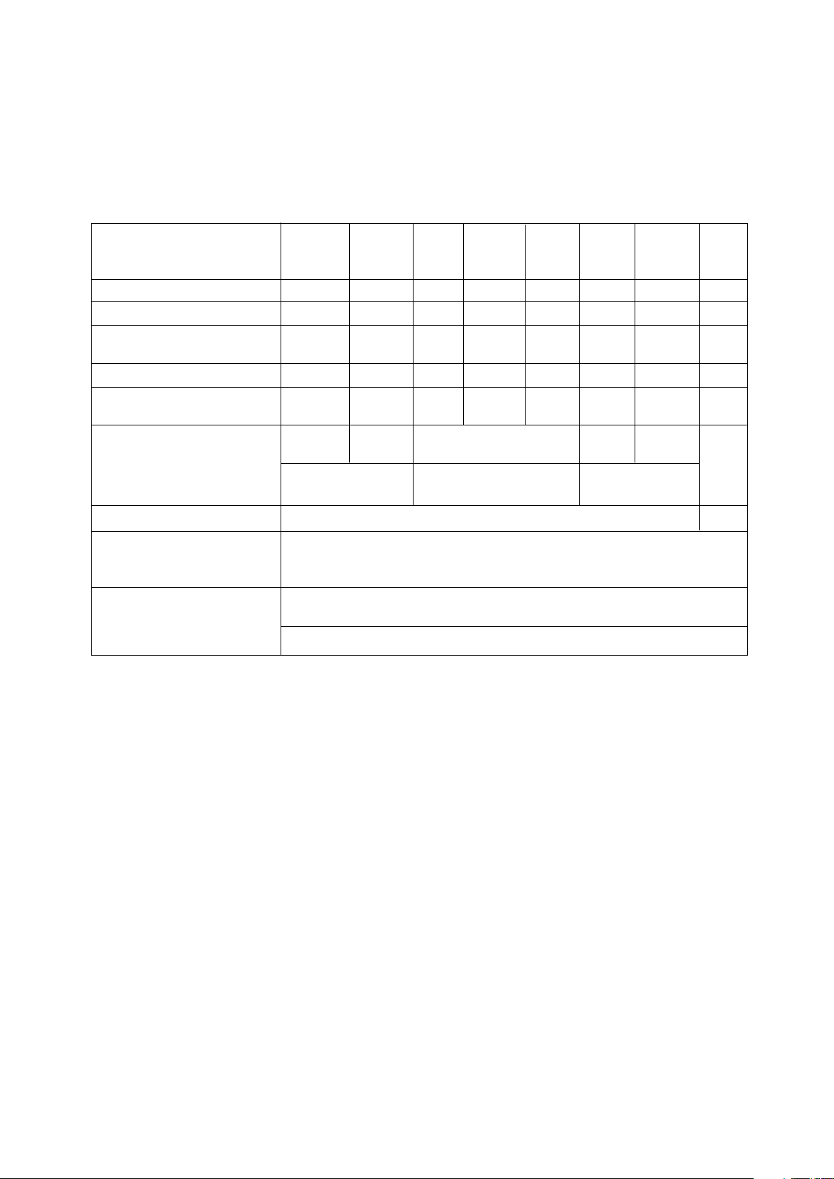
DH AS High High
Standard AlGaAs Eff. Perf. Emerald
Parameter Red Red Red Orange Yellow Green Green Units
DC Forward Current
[1]
50 30 30 30 20 30 30 mA
Peak Forward Current
[2]
1000 300 90 90 60 90 90 mA
DC Forward Voltage 6 6 6 6 V
(Resistor Lamps Only)
Reverse Voltage (I
R
= 100 µA)5 555555V
Transient Forward Current
[3]
2000 500 500 500 500 500 500 mA
(10 µs Pulse)
Operating Temperature Range: -55 to -40 to -55 to +100 -40 to -20 to
Non-Resistor Lamps +100 +100 +100 +100
°C
Resistor Lamps -40 to +85 -20 to
+85
Storage Temperature Range °C
For Thru Hole Devices 260°C for 5 Seconds
Wave Soldering Temperature
[1.6 mm (0.063 in.) from body]
For Surface Mount Devices:
Convective IR 235°C for 90 Seconds
Vapor Phase 215°C for 3 Minutes
Absolute Maximum Ratings at T
A
= 25°C
-55 to +100
Notes:
1. See Figure 5 for current derating vs. ambient temperature. Derating is not applicable to resistor lamps.
2. Refer to Figure 6 showing Max. Tolerable Peak Current vs. Pulse Duration to establish pulsed operating conditions.
3. The transient peak current is the maximum non-recurring peak current the device can withstand without failure. Do not
operate these lamps at this high current.
1-178
Electrical/Optical Characteristics, T
A
= 25°C
Standard Red
Device
HLMP- Parameter Symbol Min. Typ. Max. Units Test Conditions
6000 0.5 1.2
6001 Luminous Intensity
[1]
I
v
1.3 3.2 mcd IF = 10 mA
6203 to 0.5 1.2
6208
Forward Voltage V
F
1.4 1.6 2.0 V IF = 10 mA
All Reverse Breakdown V
R
5.0 12.0 V IR = 100 µA
Voltage
P005 Included Angle Between 125
Half Intensity Points
[2]
2θ1/2 Deg.
All 90
Others
Peak Wavelength λ
PEAK
655 nm
Dominant Wavelength
[3]
λ
d
640 nm
Spectral Line Half Width ∆λ
1/2
24 nm
All Speed of Response τ
s
15 ns
Capacitance C 100 pF VF = 0; f = 1 MHz
Thermal Resistance Rθ
J-PIN
170 °C/W Junction-to-Cathode
Lead
Luminous Efficacy
[4]
η
v
65 lm/W

1-179
Device
HLMP- Parameter Symbol Min. Typ. Max. Units Test Conditions
P102 4.0 20.0
P105 8.6 30.0
Q101 22.0 45.0
Q105 Luminous Intensity I
v
22.0 55.0 mcd
Q150 1.0 1.8
Q155 2.0 4.0
Q101 1.8 2.2
IF = 20 mA
P205/P505 Forward Voltage V
F
1.8 2.2 V
Q101/Q105
Q150/Q155 1.6 1.8 IF = 1 mA
All Reverse Breakdown V
R
5.0 15.0 V IR = 100 µA
Voltage
P105 125
Q101/Q150 Included Angle Between 2θ1/2 90 Deg.
Half Intensity Points
[2]
Q105/Q155 28
Peak Wavelength λ
PEAK
645 nm Measured at Peak
Dominant Wavelength
[3]
λ
d
637 nm
Spectral Line Half Width ∆λ
1/2
20 nm
All Speed of Response τ
s
30 ns Exponential Time
Constant; e
-t/τ
Capacitance C 30 pF VF = 0; f = 1 MHz
Thermal Resistance Rθ
J-PIN
170 °C/W Junction-to
Cathode Lead
Luminous Efficacy
[4]
η
v
80 lm/W
DH AS AlGaAs Red
IF = 1 mA
IF = 20 mA
s
1-180
Device
HLMP- Parameter Symbol Min. Typ. Max. Units Test Conditions
P202 1.0 5.0
P205 1.0 8.0
6300 1.0 10.0 IF = 10 mA
6305 3.4 24.0
7000 Luminous Intensity
[1]
I
v
0.4 1.0 mcd IF = 2 mA
6600 1.3 5.0 VF = 5.0 Volts
6620 0.8 2.0
6653 to 1.0 3.0 IF = 10 mA
6658
All Forward Voltage V
F
1.5 1.8 3.0 V IF = 10 mA
(Nonresistor Lamps)
6600 9.6 13.0
I
F
mA VF = 5.0 V
6620 3.5 5.0
All Reverse Breakdown V
R
5.0 30.0 V IR = 100 µA
Voltage
P205 125
6305 Included Angle Between 2θ1/2 28 Deg.
Half Intensity Points
[2]
All 90
Diffused
Peak Wavelength λ
PEAK
635 nm Measured at Peak
Dominant Wavelength
[3]
λ
d
626 nm
Spectral Line Half Width ∆λ
1/2
40 nm
All Speed of Response τ
s
90 ns
Capacitance C 11 pF VF = 0; f = 1 MHz
Thermal Resistance Rθ
J-PIN
170 °C/W Junction-to-Cathode
Lead
Luminous Efficacy
[4]
η
v
145 lm/W
High Efficiency Red
Forward Current
(Resistor Lamps)

1-181
Device
HLMP- Parameter Symbol Min. Typ. Max. Units Test Conditions
P402 1.0 4.0
P405 Luminous Intensity I
v
1.0 6 mcd IF = 10 mA
Q400 1.0 8
Forward Voltage V
F
1.5 1.9 3.0 V IF = 10 mA
All Reverse Breakdown V
R
5.0 30.0 V IR = 100 µA
Voltage
P405 Included Angle Between 125
Half Intensity Points
[2]
2θ1/2 Deg.
Q400 90
Peak Wavelength λ
PEAK
600 nm
Dominant Wavelength
[3]
λ
d
602 nm Measured at Peak
Spectral Line Half Width ∆λ
1/2
40 nm
All Speed of Response τ
s
260 ns
Capacitance C 4 pF VF = 0; f = 1 MHz
Thermal Resistance Rθ
J-PIN
170 °C/W Junction-to-Cathode
Lead
Luminous Efficacy
[4]
η
v
380 lm/W
Orange

1-182
Yellow
Device
HLMP- Parameter Symbol Min. Typ. Max. Units Test Conditions
P302 1.0 3.0
P305 1.0 4.0
IF = 10 mA
6400 1.0 9.0
6405 Luminous Intensity
[1]
I
v
3.6 20 mcd
7019 0.4 0.6 IF = 2 mA
6700 1.4 5.0 VF = 5.0 Volts
6720 0.9 2.0
6753 to 1.0 3.0 IF = 10 mA
6758
All Forward Voltage V
F
2.0 2.4 V IF = 10 mA
(Nonresistor Lamps)
6700 9.6 13.0
Forward Current I
F
mA VF = 5.0 V
6720 (Resistor Lamps) 3.5 5.0
All Reverse Breakdown V
R
5.0 50.0 V
Voltage
P305 125
6405 Included Angle Between 2θ1/2 28 Deg.
Half Intensity Points
[2]
All 90
Diffused
Peak Wavelength λ
PEAK
583 nm Measured at Peak
Dominant Wavelength
[3]
λ
d
585 nm
Spectral Line Half Width ∆λ
1/2
36 nm
All Speed of Response τ
s
90 ns
Capacitance C 15 pF VF = 0; f = 1 MHz
Thermal Resistance Rθ
J-PIN
170 °C/W Junction-to-Cathode
Lead
Luminous Efficacy
[4]
η
v
500 lm/W
1-183
High Performance Green
Device
HLMP- Parameter Symbol Min. Typ. Max. Units Test Conditions
P502 1.0 3.0
P505 1.0 5.0
6500 1.0 7.0 IF = 10 mA
6505 4.2 20.0
7040 Luminous Intensity
[1]
I
v
0.4 0.6 mcd IF = 2 mA
6800 1.6 5.0 VF = 5.0 Volts
6820 0.8 2.0
6853 to 1.0 3.0 IF = 10 mA
6858
All Forward Voltage V
F
2.1 2.7 V IF = 10 mA
(Nonresistor Lamps)
6800 9.6 13.0
Forward Current I
F
mA VF = 5.0 V
6820 (Resistor Lamps) 3.5 5.0
All Reverse Breakdown V
R
5.0 50.0 V IR = 100 µA
Voltage
P505 125
6505 Included Angle Between 2θ1/2 28 Deg.
Half Intensity Points
[2]
All 90
Diffused
Peak Wavelength λ
PEAK
565 nm
Dominant Wavelength
[3]
λ
d
569 nm
Spectral Line Half Width ∆λ
1/2
28 nm
All Speed of Response τ
s
500 ns
Capacitance C 18 pF VF = 0; f = 1 MHz
Thermal Resistance Rθ
J-PIN
170 °C/W Junction-to-Cathode
Lead
Luminous Efficacy
[4]
η
v
595 lm/W
Notes:
1. The luminous intensity for arrays is tested to assure a 2.1 to 1.0 matching between elements. The average luminous intensity
for an array determines its light output category bin. Arrays are binned for luminous intensity to allow Iv matching between
arrays.
2. θ1/2 is the off-axis angle where the luminous intensity is half the on-axis value.
3. Dominant wavelength, λd, is derived from the CIE Chromaticity Diagram and represents the single wavelength that defines the
color of the device.
4. Radiant intensity, Ie, in watts/steradian, may be calculated from the equation Ie =Iv/ηv, where Iv is the luminous intensity in
candelas and ηv is the luminous efficacy in lumens/watt.

1-184
Device
HLMP- Parameter Symbol Min. Typ. Max. Units Test Conditions
P605 Luminous Intensity I
v
1.0 1.5 mcd IF = 10 mA
Q600 1.0 1.5
Forward Voltage V
F
2.2 3.0 V IF = 10 mA
Reverse Breakdown V
R
5.0 V IR = 100 µA
Voltage
P605 Included Angle Between 125
Half Intensity Points
[2]
2θ1/2 Deg.
Q600 90
Peak Wavelength λ
PEAK
558 nm
Dominant Wavelength
[3]
λ
d
560 nm Measured at Peak
Spectral Line Half Width ∆λ
1/2
24 nm
P605/
Q600 Speed of Response τ
s
3100 ns
Capacitance C 35 pF VF = 0; f = 1 MHz
Thermal Resistance Rθ
J-PIN
170 °C/W Junction-to-Cathode
Lead
Luminous Efficacy
[4]
η
v
656 lm/W
Emerald Green
[1]
Note:
1. Please refer to Application Note 1061 for information comparing stnadard green and emerald green light ouptut degradation.

1-185
Standard Red, DH As AlGaAs Red
Standard Red and DH AS
AlGaAs Red
High Efficiency Red, Orange,
Yellow, and High
Performance Green
HER, Orange, Yellow, and
High Performance Green,
and Emerald Green
Low Current
Figure 1. Relative Intensity vs. Wavelength.
Figure 2. Forward Current vs. Forward Voltage. (Non-Resistor Lamp)
Figure 3. Relative Luminous Intensity vs. Forward Current. (Non-Resistor Lamp)

1-186
Figure 4. Relative Efficiency (Luminous Intensity per Unit Current) vs. Peak Current (Non-Resistor Lamps).
Figure 5. Maximum Forward dc Current vs. Ambient Temperature. Derating Based on T
J
MAX = 110 °C
(Non-Resistor Lamps).
Figure 6. Maximum Tolerable Peak Current vs. Pulse Duration. (IDC MAX as per MAX Ratings) (Non-Resistor
Lamps).
Standard Red
DH As AlGaAs RedStandard Red
HER, Orange, Yellow, and High
Performance Green DH As AlGaAs Red
HER, Orange, Yellow, and
High Performance Green,
and Emerald Green

1-187
Figure 9. Relative Intensity vs. Angular Displacement.
Figure 7. Resistor Lamp Forward Current vs. Forward
Voltage.
Figure 8. Resistor Lamp Luminous Intensity vs.
Forward Voltage.
 Loading...