

Page 1
Hitachi Command Suite
Dynamic Link Manager
(for Solaris) User Guide
Document Organization
Product Version
Getting Help
Contents
MK-92DLM114-28
Page 2

© 2014 Hitachi, Ltd. All rights reserved.
No part of this publication may be reproduced or transmitted in any form or by any means,
electronic or mechanical, including photocopying and recording, or stored in a database or retrieval
system for any purpose without the express written permission of Hitachi, Ltd.
Hitachi, Ltd., reserves the right to make changes to this document at any time without notice and
assumes no responsibility for its use. This document contains the most current information available
at the time of publication. When new or revised information becomes available, this entire
document will be updated and distributed to all registered users.
Some of the features described in this document might not be currently available. Refer to the most
recent product announcement for information about feature and product availability, or contact
Hitachi Data Systems Corporation at
Notice: Hitachi, Ltd., products and services can be ordered only under the terms and conditions of
the applicable Hitachi Data Systems Corporation agreements. The use of Hitachi, Ltd., products is
governed by the terms of your agreements with Hitachi Data Systems Corporation.
Hitachi is a registered trademark of Hitachi, Ltd., in the United States and other countries. Hitachi
Data Systems is a registered trademark and service mark of Hitachi, Ltd., in the United States and
other countries.
Archivas, Essential NAS Platform, HiCommand, Hi-Track, ShadowImage, Tagmaserve, Tagmasoft,
Tagmasolve, Tagmastore, TrueCopy, Universal Star Network, and Universal Storage Platform are
registered trademarks of Hitachi Data Systems.
AIX, AS/400, DB2, Domino, DS6000, DS8000, Enterprise Storage Server, ESCON, FICON,
FlashCopy, IBM, Lotus, MVS, OS/390, RS/6000, S/390, System z9, System z10, Tivoli, VM/ESA,
z/OS, z9, z10, zSeries, z/VM, and z/VSE are registered trademarks or trademarks of International
Business Machines Corporation.
https://portal.hds.com.
All other trademarks, service marks, and company names in this document or web site are
properties of their respective owners.
Microsoft product screen shots are reprinted with permission from Microsoft Corporation.
Notice on Export Controls. The technical data and technology inherent in this Document may be
subject to U.S. export control laws, including the U.S. Export Administration Act and its associated
regulations, and may be subject to export or import regulations in other countries. Reader agrees to
comply strictly with all such regulations and acknowledges that Reader has the responsibility to
obtain licenses to export, re-export, or import the Document and any Compliant Products.
ii
Hitachi Dynamic Link Manager (for Solaris) User Guide
Page 3

Contents
Preface.................................................................................................xiii
Intended audience...................................................................................................xiv
Product version....................................................................................................... xiv
Release notes..........................................................................................................xiv
Document revision level........................................................................................... xiv
Document organization.............................................................................................xv
Related documents...................................................................................................xv
Document conventions.............................................................................................xvi
Conventions for storage capacity values.................................................................... xvi
Accessing product documentation............................................................................ xvii
Getting help........................................................................................................... xvii
Comments.............................................................................................................xviii
1 Overview of HDLM................................................................................1-1
What is HDLM?.......................................................................................................1-2
HDLM Features.......................................................................................................1-2
2 HDLM Functions................................................................................... 2-1
Devices Managed by HDLM......................................................................................2-3
System Configuration.............................................................................................. 2-3
LU Configuration.....................................................................................................2-5
Program Configuration............................................................................................ 2-6
Position of the HDLM Driver and HDLM Device..........................................................2-8
Logical Device Files for HDLM Devices...................................................................... 2-9
Distributing a Load Using Load Balancing................................................................2-10
Paths to Which Load Balancing Is Applied.........................................................2-12
When Using the Thunder 9500V Series, or Hitachi AMS/WMS series..........2-12
When Using Other Than the Thunder 9500V Series and Hitachi AMS/WMS
Series................................................................................................... 2-13
Load Balancing Algorithms...............................................................................2-14
Performing Failovers and Failbacks Using Path Switching......................................... 2-15
Automatic Path Switching................................................................................ 2-16
Automatic Failovers............................................................................... 2-16
Automatic Failbacks...............................................................................2-18
Manual Path Switching.................................................................................... 2-18
Hitachi Dynamic Link Manager (for Solaris) User Guide
iii
Page 4

Path Status Transition..................................................................................... 2-19
The Online Path Status.......................................................................... 2-19
The Offline Path Status.......................................................................... 2-20
Status Transitions of a Path....................................................................2-20
Intermittent Error Monitoring (Functionality When Automatic Failback Is Used)......... 2-23
Checking Intermittent Errors............................................................................2-23
Setting Up Intermittent Error Monitoring...........................................................2-23
Intermittent Error Monitoring Actions............................................................... 2-24
When an Intermittent Error Occurs......................................................... 2-24
When an Intermittent Error Does Not Occur............................................ 2-25
When the Conditions for an Intermittent Error Are Changed During Error
Monitoring............................................................................................ 2-26
When a User Changes the Intermittent Error Information.................................. 2-27
Detecting Errors by Using Path Health Checking...................................................... 2-28
Distributing a Load by Using the Dynamic I/O Path Control Function.........................2-29
What is the Dynamic Load Balance Control Function..........................................2-29
Dynamic I/O Path Control Function.................................................................. 2-29
Error Management................................................................................................ 2-30
Types of Collected Logs...................................................................................2-31
Filtering of Error Information........................................................................... 2-32
Collecting Error Information Using the Utility for Collecting HDLM Error Information
(DLMgetras)................................................................................................... 2-33
Collecting Audit Log Data.......................................................................................2-33
Categories and Audit Events that HDLM Can Output to the Audit Log................. 2-35
Requirements for Outputting Audit Log Data.....................................................2-38
Destination and Filtering of Audit Log Data....................................................... 2-39
Audit Log Data Formats...................................................................................2-40
Integrated HDLM management using Global Link Manager.......................................2-41
Cluster Support.....................................................................................................2-42
3 Creating an HDLM Environment............................................................. 3-1
HDLM System Requirements....................................................................................3-3
Hosts and OSs Supported by HDLM................................................................... 3-3
Storage Systems Supported by HDLM................................................................ 3-4
Storage Systems..................................................................................... 3-4
HBAs......................................................................................................3-5
When Handling Intermediate Volumes Managed by Hitachi RapidXchange...3-5
Cluster Software Supported by HDLM.................................................................3-6
Volume Manager Supported by HDLM................................................................ 3-6
Combinations of Cluster Software and Volume Managers Supported by HDLM.......3-7
For the Solaris Cluster or VCS Environment............................................... 3-7
When Creating an Oracle9i RAC Environment.......................................... 3-11
When Creating an Oracle RAC 10g Environment...................................... 3-11
When Creating an Oracle RAC 11g Environment...................................... 3-25
Virtualization Environments Supported by HDLM............................................... 3-35
Memory and Disk Capacity Requirements......................................................... 3-36
Memory Requirements...........................................................................3-36
Disk Capacity Requirements................................................................... 3-36
Number of LUs and Paths Supported in HDLM...................................................3-37
Flow for Creating an HDLM Environment.................................................................3-37
HDLM Installation Types........................................................................................3-38
Notes on Creating an HDLM Environment............................................................... 3-39
iv
Hitachi Dynamic Link Manager (for Solaris) User Guide
Page 5

Notes on Hardware Settings............................................................................ 3-39
Notes on Installation.......................................................................................3-40
Notes on Related Software.............................................................................. 3-44
Notes on Command Execution......................................................................... 3-45
Notes on the Disk Label...................................................................................3-45
Installing HDLM.................................................................................................... 3-45
Preparations for a New Installation of HDLM.....................................................3-45
Performing Operations on Devices to Be Managed by HDLM..................... 3-45
Apply Solaris Patches.............................................................................3-47
Set Up the Hardware............................................................................. 3-47
Set Up the /kernel/drv/sd.conf File......................................................... 3-48
Switch the Kernel Mode ........................................................................ 3-48
Set Up the /etc/system File.................................................................... 3-49
Set Up the /etc/syslog.conf or /etc/rsyslog.conf File.................................3-49
Set Up VxVM.........................................................................................3-50
Set Up SDS and SVM............................................................................. 3-50
Set Up Solaris Cluster............................................................................ 3-51
Setting up a Solaris 11 environment........................................................3-52
Preparation for Performing an Unattended Installation of HDLM......................... 3-54
Performing a New Installation of HDLM (When Solaris Cluster Is Not Being Used)3-55
Performing a New Installation of HDLM (When Solaris Cluster Is Being Used)..... 3-62
Using the HDLM Device Unconfiguration Function When Performing a New
Installation of HDLM....................................................................................... 3-72
Preparations for an Upgrade Installation or Re-installation of HDLM................... 3-73
Performing an Upgrade Installation or Re-installation of HDLM...........................3-73
Installing HDLM in an LDoms Environment....................................................... 3-78
Configuring a Boot Disk Environment......................................................................3-82
Overview of Configuring a Boot Disk Environment............................................. 3-83
Procedure for Configuring a Boot Disk Environment...........................................3-83
Migration from an Existing HDLM Environment........................................ 3-84
Migration by Installing HDLM in the Existing Local Boot Disk Environment. 3-85
Migration by Installing HDLM in the Existing Boot Disk Environment..........3-87
Migration by Building a New Pre-Migration Environment........................... 3-89
Setting Up the Post-Migration Environment............................................. 3-91
Configuring a Boot Disk Environment for a ZFS File System......................................3-96
Boot Disk Environment that uses a ZFS File System...........................................3-96
Creating a ZFS Boot Disk Environment (for Solaris 10).......................................3-98
Copying the local boot disk environment to the LUs (SCSI device) in the
storage system......................................................................................3-99
Replacing the ZFS boot disk environment on the SCSI device with the ZFS
boot disk environment on the HDLM device........................................... 3-101
Creating a ZFS Boot Disk Environment (for Solaris 11).....................................3-102
Moving a local boot disk environment to an LU (HDLM device) in a storage
system................................................................................................3-102
Configuring a ZFS Boot Disk Environment after the Migration..................3-104
Replacing an LU with Another LU in the Boot Disk Environment.............. 3-106
Performing a Check after Restart.......................................................... 3-108
Migrating from a ZFS Boot Disk Environment to the Local Boot Disk Environment (for
Solaris 10)....................................................................................................3-109
Migrating from a ZFS Boot Disk Environment to the Local Boot Disk Environment (for
Solaris 11)....................................................................................................3-110
Replacing an LU with Another LU in the Boot Disk Environment.............. 3-110
Hitachi Dynamic Link Manager (for Solaris) User Guide
v
Page 6

Creating a New Boot Environment........................................................ 3-112
Configuring the Post-Migration ZFS Boot Disk Environment.....................3-113
Migrating to the ZFS Boot Disk Environment.......................................... 3-114
Performing a Check after Restart.......................................................... 3-115
Migrating from a Boot Disk Environment to the Local Boot Disk Environment...........3-116
Configuring a Mirrored Boot Disk Environment Incorporating SVM.......................... 3-121
Precautions.................................................................................................. 3-121
Configuring a Boot Disk Environment in Which HDLM Manages the Boot Disk and
Mirroring the Environment by Using SVM........................................................ 3-122
Configuring a Boot Disk Environment in Which HDLM Manages the Boot Disk,
from the Local Boot Disk Environment...................................................3-122
Mirroring a Boot Disk Environment in Which HDLM Manages the Boot Disk by
Using SVM.......................................................................................... 3-123
Placing the Boot Disks Under HDLM Management by Installing HDLM to a Mirrored
Boot Disk Environment Incorporating SVM...................................................... 3-126
Installing HDLM and then Configuring the Environment.......................... 3-127
Placing the Boot Disks Under HDLM Management.................................. 3-127
Removing HDLM........................................................................................... 3-133
Excluding the Prepared LUs from HDLM Management............................ 3-133
Configuring an Environment and then Removing HDLM.......................... 3-133
Checking the Path Configuration...........................................................................3-139
Setting Up HDLM Functions..................................................................................3-140
Checking the Current Settings........................................................................3-140
Setting Up the HDLM Functions......................................................................3-140
Setting Up Load Balancing....................................................................3-141
Setting Up Path Health Checking...........................................................3-142
Setting Up the Automatic Failback Function........................................... 3-142
Setting Up Intermittent Error Monitoring............................................... 3-143
Setting Up Dynamic I/O Path Control.................................................... 3-144
Setting the Error Log Collection Level....................................................3-144
Setting the Trace Level........................................................................ 3-145
Setting the Error Log File Size...............................................................3-145
Setting the Number of Error Log Files................................................... 3-146
Setting the Trace File Size.................................................................... 3-146
Setting the Number of Trace Files.........................................................3-147
Setting Up Audit Log Data Collection.....................................................3-147
Setting the Audit Log Facility................................................................ 3-148
Checking the Updated Settings...................................................................... 3-149
Setting up Integrated Traces................................................................................3-149
Notes on Using the Hitachi Network Objectplaza Trace Library......................... 3-150
Displaying the Hitachi Network Objectplaza Trace Library setup Menu.............. 3-151
Changing the Size of Integrated Trace Files.................................................... 3-151
Changing the Number of Integrated Trace Files.............................................. 3-152
Changing the Buffer Size Per Monitoring Interval Duration............................... 3-152
Adjusting the Number of Messages to Be Output Per Monitoring Interval.......... 3-153
Finishing the Hitachi Network Objectplaza Trace Library Settings......................3-155
Applying the Hitachi Network Objectplaza Trace Library Settings...................... 3-155
Creating File Systems for HDLM (When Volume Management Software Is Not Used)3-156
Setting Up VxVM................................................................................................. 3-157
Creating a Disk Group................................................................................... 3-157
Creating VxVM Volumes.................................................................................3-160
Removing Devices from VxVM........................................................................3-160
vi
Hitachi Dynamic Link Manager (for Solaris) User Guide
Page 7

Devices to Be Removed from VxVM.......................................................3-161
Removing Devices from VxVM on a Controller Basis............................... 3-162
Removing Devices From VxVM on a Path Basis...................................... 3-166
Actions To Be Taken if an sd or ssd Device Has Not Been Suppressed from
VxVM..................................................................................................3-170
Introducing VxVM while Using HDLM.............................................................. 3-174
Linking VxVM and Solaris Cluster....................................................................3-174
Setting Up SDS................................................................................................... 3-176
Notes...........................................................................................................3-176
Registering HDLM Devices............................................................................. 3-177
To Use a Local Metadevice................................................................... 3-177
To Use a Shared Diskset...................................................................... 3-178
Setting Up SVM...................................................................................................3-180
Notes...........................................................................................................3-180
Registering HDLM Devices............................................................................. 3-181
To Use a Local Volume.........................................................................3-181
To Use a Shared Diskset...................................................................... 3-181
Setting Up VCS................................................................................................... 3-183
Removing HDLM................................................................................................. 3-184
Overview of HDLM Removal...........................................................................3-184
Preparations for HDLM Removal.....................................................................3-185
Performing Operations on HDLM-Managed Devices................................ 3-185
Remove Solaris Cluster Settings............................................................3-186
Remove VCS Settings...........................................................................3-188
Remove VxVM Settings........................................................................ 3-189
Remove SDS Settings...........................................................................3-189
Remove SVM Settings.......................................................................... 3-190
Removing HDLM........................................................................................... 3-191
Removing HDLM from the Local Boot Disk Environment..........................3-191
Removing HDLM from the Boot Disk Environment.................................. 3-193
Removing HDLM from an LDoms Environment....................................... 3-193
Settings Needed After HDLM Removal............................................................ 3-198
VxVM Settings..................................................................................... 3-198
SDS Settings....................................................................................... 3-198
SVM Settings.......................................................................................3-198
Solaris Cluster Settings.........................................................................3-198
File System Settings.............................................................................3-200
Application Program Settings................................................................3-200
Removing Hitachi Network Objectplaza Trace Library (HNTRLib2).....................3-200
Removing Hitachi Network Objectplaza Trace Library (HNTRLib)...................... 3-201
4 HDLM Operation................................................................................... 4-1
Notes on Using HDLM............................................................................................. 4-2
Displaying Path Information.............................................................................. 4-2
When a Path Error is Detected...........................................................................4-2
iostat Command............................................................................................... 4-2
Storage System................................................................................................ 4-3
Command Execution......................................................................................... 4-3
Using a Sun HBA.............................................................................................. 4-3
Starting Solaris in Single-User Mode...................................................................4-3
Upgrading Solaris............................................................................................. 4-4
Operation in Single-User Mode.......................................................................... 4-4
vii
Hitachi Dynamic Link Manager (for Solaris) User Guide
Page 8

Initializing HDLM When the Host Is Started in Single-User Mode.................4-4
Tasks that Can Be Performed in Single-User Mode.....................................4-5
Maintenance Tasks on Devices Connected by Paths in the Boot Disk Environment
.......................................................................................................................4-6
HDLM Operations Using Commands......................................................................... 4-6
Notes on Using Commands................................................................................4-6
Viewing Path Information..................................................................................4-6
Changing the Status of Paths.............................................................................4-7
Changing the Status of Paths to Online.....................................................4-7
Changing the Status of Paths to Offline(C)................................................ 4-8
Viewing LU Information.....................................................................................4-9
Displaying Corresponding Information About an HDLM Device, sd or ssd Device, and
LDEV............................................................................................................... 4-9
Initializing Statistical Information for Paths....................................................... 4-10
Viewing and Setting Up the Operating Environment...........................................4-11
Viewing the Operating Environment........................................................4-11
Setting Up the Operating Environment.................................................... 4-11
Viewing License Information............................................................................4-12
Updating the License.......................................................................................4-13
Viewing HDLM Version Information.................................................................. 4-13
Viewing HDLM Component Information............................................................ 4-14
Starting and Stopping the HDLM Manager...............................................................4-15
Starting the HDLM Manager.............................................................................4-15
Stopping the HDLM Manager........................................................................... 4-15
HDLM Resident Processes......................................................................................4-16
Changing the Configuration of the HDLM Operating Environment............................. 4-16
Precautions Regarding Changes to the Configuration of an HDLM Operating
Environment...................................................................................................4-17
Changing the Configuration of a System that Uses HDLM......................... 4-17
When the Path Configuration Is Changed................................................ 4-17
Switching the Kernel Mode.....................................................................4-19
When the Path Configuration Is Changed in a Boot Disk Environment....... 4-19
Dynamic Reconfiguration (DR) for Solaris................................................4-20
Overview of Reconfiguring the HDLM Device.....................................................4-20
Reconfiguring the HDLM Device..............................................................4-20
Notes on Reconfiguring the HDLM Device................................................4-21
Adding a New Logical Unit...............................................................................4-22
Notes................................................................................................... 4-22
Adding a New LU (When Not Using Solaris Cluster)..................................4-23
Adding a New LU By Restarting the Nodes (When Using Solaris Cluster)....4-25
Adding a New LU Via Dynamic Reconfiguration (When Using Solaris Cluster)
............................................................................................................4-31
Configuration Changes Such as Deleting a Logical Unit...................................... 4-36
Changing the Configuration by Restarting the Host.................................. 4-37
Deleting an LU via Dynamic Reconfiguration............................................4-42
Adding a Path to an Existing LU by Dynamic Reconfiguration............................. 4-44
Deleting a Path to an Existing LU by Dynamic Reconfiguration........................... 4-47
Specifying Whether a Logical Unit Is To Be Managed by HDLM (When Not Using
Solaris Cluster)............................................................................................... 4-48
Changing an HDLM-managed Device to a Non-HDLM-Managed Device......4-49
Changing a Non-HDLM-Managed Device to an HDLM-Managed Device...... 4-49
viii
Hitachi Dynamic Link Manager (for Solaris) User Guide
Page 9

Specifying Whether a Logical Unit Is To Be Managed by HDLM (When Using Solaris
Cluster)..........................................................................................................4-52
Changing an HDLM-Managed Device to a Non-HDLM-Managed Device...... 4-52
Changing a Non-HDLM-Managed Device to an HDLM-Managed Device (When
the Node Must Be Restarted)................................................................. 4-57
Changing a Non-HDLM-Managed Device to an HDLM-Managed Device (For
Dynamic Reconfiguration)...................................................................... 4-63
Inheriting logical device names during storage system migration........................4-68
5 Troubleshooting....................................................................................5-1
Information collected by using the DLMgetras utility for collecting HDLM error
information.............................................................................................................5-2
Checking Error Information in Messages...................................................................5-2
What To Do for a Path Error.................................................................................... 5-3
Examining the Messages................................................................................... 5-5
Obtain Path Information....................................................................................5-5
Identifying the Error Path..................................................................................5-5
Narrowing Down the Hardware That Might Have Caused the Error....................... 5-5
Identifying the Error Location and Correcting any Hardware Errors.......................5-5
Placing the Path Online..................................................................................... 5-5
Actions to Take for a Path Error in a Boot Disk Environment...................................... 5-6
Path Errors During Boot Processing....................................................................5-6
When a Path Error Occurs at the Initial Stage of Boot Processing................5-6
When a Path Error Occurs After the HDLM Driver Starts Path Processing.....5-6
Path Errors After Boot Processing Completes...................................................... 5-7
What To Do for a Program Error.............................................................................. 5-7
Examining the Messages................................................................................... 5-8
Obtaining Program Information......................................................................... 5-8
What To Do for the Program Error..................................................................... 5-8
Contacting Your HDLM Vendor or Maintenance Company.................................... 5-9
What To Do for Other Errors....................................................................................5-9
6 Command Reference.............................................................................6-1
Overview of the HDLM Command dlnkmgr................................................................6-2
clear (Returns the Path Statistics to the Initial Value)................................................ 6-3
Format.............................................................................................................6-3
To set the path statistics to 0...................................................................6-3
To display the format of the clear operation.............................................. 6-3
Parameters...................................................................................................... 6-3
To set the path statistics to 0...................................................................6-3
To display the format of the clear operation.............................................. 6-4
help (Displays the Operation Format)....................................................................... 6-4
Format.............................................................................................................6-4
Parameter........................................................................................................6-4
offline (Places Paths Offline)....................................................................................6-6
Format.............................................................................................................6-6
To place paths offline.............................................................................. 6-6
To display the format of the offline operation............................................6-7
Parameters...................................................................................................... 6-7
To place paths offline.............................................................................. 6-7
To display the format of the offline operation.......................................... 6-10
ix
Hitachi Dynamic Link Manager (for Solaris) User Guide
Page 10

online (Places Paths Online)...................................................................................6-12
Format...........................................................................................................6-12
To place paths online.............................................................................6-12
To display the format of the online operation.......................................... 6-12
Parameters.....................................................................................................6-12
To place paths online.............................................................................6-12
To display the format of the online operation.......................................... 6-16
set (Sets Up the Operating Environment)................................................................6-17
Format...........................................................................................................6-17
To set up the HDLM operating environment............................................ 6-17
To display the format of the set operation...............................................6-18
Parameters.....................................................................................................6-18
To set up the HDLM operating environment............................................ 6-18
To display the format of the set operation...............................................6-32
view (Displays Information)................................................................................... 6-34
Format...........................................................................................................6-34
To display program information..............................................................6-34
To display path information....................................................................6-34
To display LU information...................................................................... 6-35
To display HBA port information............................................................. 6-35
To display CHA port information............................................................. 6-35
To display corresponding information about an HDLM device, sd or ssd device,
and LDEV..............................................................................................6-35
To display the format of the view operation.............................................6-36
Parameters.....................................................................................................6-36
To display program information..............................................................6-36
To display path information....................................................................6-43
To display LU information...................................................................... 6-57
To display HBA port information............................................................. 6-70
To display CHA port information............................................................. 6-71
To display corresponding information about an HDLM device, sd or ssd device,
and LDEV..............................................................................................6-72
To display view operation format............................................................6-73
monitor (Displays I/O Information at a Specified Interval)........................................6-74
Format...........................................................................................................6-75
To display I/O information for each HBA port.......................................... 6-75
To display I/O information for each CHA port.......................................... 6-75
To display the monitor operation format................................................. 6-75
Parameters.....................................................................................................6-75
To display I/O information for each HBA port.......................................... 6-76
To display I/O information for each CHA port.......................................... 6-77
To display monitor operation format....................................................... 6-78
add (Adds a Path Dynamically)...............................................................................6-79
Format...........................................................................................................6-79
To Add a Path Dynamically.....................................................................6-79
To Display the Format of the add Operation............................................ 6-79
Parameters.....................................................................................................6-79
To Add a Path Dynamically.....................................................................6-79
To Display the Format of the add Operation............................................ 6-80
delete (Deletes a Path Dynamically)....................................................................... 6-80
Format...........................................................................................................6-81
To Delete a Path Dynamically.................................................................6-81
x
Hitachi Dynamic Link Manager (for Solaris) User Guide
Page 11

To Display the Format of the delete Operation.........................................6-81
Parameters.....................................................................................................6-81
To Delete a Path Dynamically.................................................................6-81
To Display the Format of the delete Operation.........................................6-82
7 Utility Reference................................................................................... 7-1
Overview of the Utilities.......................................................................................... 7-2
The DLMgetras Utility for Collecting HDLM Error Information......................................7-3
Format.............................................................................................................7-4
Parameters...................................................................................................... 7-4
List of Collected Error Information..................................................................... 7-6
The dlmcfgmgr Utility for Managing the HDLM Configuration....................................7-17
Format...........................................................................................................7-17
Parameters.....................................................................................................7-18
The dlminstcomp HDLM Component Installation Utility............................................ 7-20
Format...........................................................................................................7-20
Parameter...................................................................................................... 7-20
The dlmlisthdev Utility for Assisting HDLM Transitions..............................................7-20
Format...........................................................................................................7-21
Parameters.....................................................................................................7-21
The dlmsetboot Utility for Assisting Configuration of an HDLM Boot Disk Environment7-23
Format...........................................................................................................7-23
Parameters.....................................................................................................7-23
The dlmsetconf Utility for Creating the HDLM Driver Configuration Definition File.......7-23
Format...........................................................................................................7-24
Parameters.....................................................................................................7-25
Items in the storage-system-migration definition file......................................... 7-29
The dlmstart Utility for Configuring HDLM Devices...................................................7-30
Format...........................................................................................................7-30
Parameters.....................................................................................................7-30
Note.............................................................................................................. 7-31
The dlmvxexclude Utility for Assisting Creation of the VxVM Configuration File...........7-31
Format...........................................................................................................7-32
Parameters.....................................................................................................7-32
The installhdlm Utility for Installing HDLM...............................................................7-33
Format...........................................................................................................7-34
Parameters.....................................................................................................7-34
Contents of the Installation-Information Settings File........................................ 7-34
About the Log File...........................................................................................7-42
Note.............................................................................................................. 7-43
installux.sh Utility for HDLM Common Installer........................................................ 7-44
Format...........................................................................................................7-44
Parameters.....................................................................................................7-44
Log file...........................................................................................................7-45
Note.............................................................................................................. 7-45
The removehdlm Utility for Removing HDLM........................................................... 7-46
Format...........................................................................................................7-46
Parameters.....................................................................................................7-46
8 Messages............................................................................................. 8-1
Before Viewing the List of Messages.........................................................................8-3
xi
Hitachi Dynamic Link Manager (for Solaris) User Guide
Page 12

Format and Meaning of Message IDs................................................................. 8-3
Terms Used in Messages and Message Explanations............................................8-3
Components That Output Messages to Syslog.....................................................8-3
KAPL01001 to KAPL02000....................................................................................... 8-4
KAPL03001 to KAPL04000......................................................................................8-31
KAPL04001 to KAPL05000......................................................................................8-33
KAPL05001 to KAPL06000......................................................................................8-41
KAPL06001 to KAPL07000......................................................................................8-49
KAPL07001 to KAPL08000......................................................................................8-52
KAPL08001 to KAPL09000......................................................................................8-53
KAPL09001 to KAPL10000......................................................................................8-57
KAPL10001 to KAPL11000......................................................................................8-84
KAPL11001 to KAPL12000....................................................................................8-128
KAPL13001 to KAPL14000....................................................................................8-131
KAPL15001 to KAPL16000....................................................................................8-133
Return Codes for Hitachi Command Suite Common Agent Component.....................8-136
A Sun Cluster 3.2 Commands................................................................... A-1
Sun Cluster 3.2 Commands..................................................................................... A-2
B Functional Differences Between Versions of HDLM.................................. B-1
Functional Differences Between Version 6.1 or Later and Versions Earlier Than 6.1..... B-2
Functional Differences Between Version 6.0 or Later and Versions Earlier Than 6.0..... B-2
Precautions on Differences in Functionality Between HDLM 5.6.1 or Earlier and HDLM
5.6.2 or Later......................................................................................................... B-2
Acronyms and abbreviations
Glossary
Index
xii
Hitachi Dynamic Link Manager (for Solaris) User Guide
Page 13

Preface
This document describes how to use the Hitachi Dynamic Link Manager.
Intended audience
□
Product version
□
Release notes
□
Document revision level
□
Document organization
□
Related documents
□
Document conventions
□
Conventions for storage capacity values
□
Accessing product documentation
□
Getting help
□
Comments
□
Hitachi Dynamic Link Manager (for Solaris) User Guide
Preface
xiii
Page 14

Intended audience
This document is intended for storage administrators who use Hitachi
Dynamic Link Manager (HDLM) to operate and manage storage systems, and
assumes that readers have:
• Knowledge of Solaris and its management functionality
• Knowledge of Storage system management functionality
• Knowledge of Cluster software functionality
• Knowledge of Volume management software functionality
Product version
This document revision applies to HDLM for Solaris version 8.0.0 or later.
Release notes
Read the release notes before installing and using this product. They may
contain requirements or restrictions that are not fully described in this
document or updates or corrections to this document.
Document revision level
Revision Date Description
MK-92DLM114-21 November 2011 Initial Release
MK-92DLM114-22 July 2012 Revision 1, supersedes and replaces
MK-92DLM114-23 August 2012 Revision 2, supersedes and replaces
MK-92DLM114-24 November 2012 Revision 3, supersedes and replaces
MK-92DLM114-25 February 2013 Revision 4, supersedes and replaces
MK-92DLM114-26 May 2013 Revision 5, supersedes and replaces
MK-92DLM114-27 October 2013 Revision 6, supersedes and replaces
MK-92DLM114-28 April 2014 Revision 7, supersedes and replaces
MK-92DLM114-21
MK-92DLM114-22
MK-92DLM114-23
MK-92DLM114-24
MK-92DLM114-25
MK-92DLM114-26
MK-92DLM114-27
xiv
Preface
Hitachi Dynamic Link Manager (for Solaris) User Guide
Page 15
Document organization
The following table provides an overview of the contents and organization of
this document. Click the chapter title in the left column to go to that chapter.
The first page of each chapter provides links to the sections in that chapter.
Chapter/Appendix Description
Chapter 1, Overview of HDLM on
page 1-1
Chapter 2, HDLM Functions on
page 2-1
Chapter 3, Creating an HDLM
Environment on page 3-1
Chapter 4, HDLM Operation on
page 4-1
Chapter 5, Troubleshooting on
page 5-1
Chapter 6, Command Reference
on page 6-1
Chapter 7, Utility Reference on
page 7-1
Gives an overview of HDLM, and describes its
features.
Describes management targets and the system
configuration of HDLM, and the basic terms and
functions for HDLM.
Describes the procedures for setting up an HDLM
environment and the procedure for canceling those
settings.
Describes how to use HDLM by using both the HDLM
GUI and commands, and how to manually start and
stop the HDLM manager. This chapter also describes
how to configure an environment to properly operate
HDLM, such as changing the HDLM managementtarget devices that connect paths or replacing the
hardware that makes up a path. describes how to
check path information by using the Windows
management tool.
Explains how to troubleshoot a path error, HDLM
failure, or any other problems that you might
encounter.
Describes all the HDLM commands.
Describes the HDLM utilities.
Chapter 8, Messages on page
8-1
Appendix A, Sun Cluster 3.2
Commands on page A-1
Appendix B, Functional
Differences Between Versions of
HDLM on page B-1
Related documents
The following related Hitachi Command Suite documents are available on the
documentation CD:
• Hitachi Command Suite Global Link Manager Installation and
Configuration Guide, MK-95HC107
• Hitachi Command Suite Global Link Manager Messages, MK-95HC108
Hitachi Dynamic Link Manager (for Solaris) User Guide
Provides information about viewing messages output
by HDLM. It also lists and explains the HDLM
messages and shows the actions to be taken in
response to each message.
Describes the Sun Cluster 3.2 commands.
Gives precautions on differences in functionality
between HDLM versions.
Preface
xv
Page 16

• Hitachi Adaptable Modular Storage Series User's Guide
• Hitachi Simple Modular Storage Series User's Guide
• Hitachi Unified Storage Series User's Guide
• Hitachi USP Series User's Guide
• Hitachi Workgroup Modular Storage Series User's Guide
• Thunder9580V Series Disk Array Subsystem User's Guide
• Hitachi Universal Storage Platform V Hitachi Universal Storage Platform
VM User and Reference Guide
• Hitachi Virtual Storage Platform Series User's Guide
• Reference Manual / File Conversion Utility & File Access Library
Document conventions
This document uses the following typographic conventions:
Convention Description
Bold Indicates text on a window, other than the window title, including
menus, menu options, buttons, fields, and labels. Example: Click OK.
Italic Indicates a variable, which is a placeholder for actual text provided by
the user or system. Example: copy source-file target-file
Note: Angled brackets (< >) are also used to indicate variables.
Monospace
< > angled
brackets
[ ] square
brackets
{ } braces Indicates required or expected values. Example: { a | b } indicates
| vertical bar Indicates that you have a choice between two or more options or
underline
Indicates text that is displayed on screen or entered by the user.
Example: # pairdisplay -g oradb
Indicates a variable, which is a placeholder for actual text provided by
the user or system. Example: # pairdisplay -g <group>
Note: Italic font is also used to indicate variables.
Indicates optional values. Example: [ a | b ] indicates that you can
choose a, b, or nothing.
that you must choose either a or b.
arguments. Examples: [ a | b ] indicates that you can choose a, b, or
nothing. { a | b } indicates that you must choose either a or b.
Indicates the default value.
Example:
[ a | b ]
Conventions for storage capacity values
Physical storage capacity values (for example, disk drive capacity) are
calculated based on the following values:
xvi
Preface
Hitachi Dynamic Link Manager (for Solaris) User Guide
Page 17
Physical capacity unit Value
1 kilobyte (KB)
1 megabyte (MB)
1 gigabyte (GB)
1 terabyte (TB)
1 petabyte (PB)
1 exabyte (EB)
1,000 (103) bytes
1,000 KB or 1,0002 bytes
1,000 MB or 1,0003 bytes
1,000 GB or 1,0004 bytes
1,000 TB or 1,0005 bytes
1,000 PB or 1,0006 bytes
Logical storage capacity values (for example, logical device capacity) are
calculated based on the following values:
Logical capacity unit Value
1 block 512 bytes
1 KB
1 MB
1 GB
1 TB
1 PB
1,024 (210) bytes
1,024 KB or 1,0242 bytes
1,024 MB or 1,0243 bytes
1,024 GB or 1,0244 bytes
1,024 TB or 1,0245 bytes
1 EB
Accessing product documentation
The HDLM user documentation is available on the Hitachi Data Systems
Portal: https://portal.hds.com. Check this site for the most current
documentation, including important updates that may have been made after
the release of the product.
Getting help
Hitachi Data Systems Support Portal is the destination for technical support of
your current or previously-sold storage systems, midrange and enterprise
servers, and combined solution offerings. The Hitachi Data Systems customer
support staff is available 24 hours a day, seven days a week. If you need
technical support, log on to the Hitachi Data Systems Support Portal for
contact information:
Hitachi Data Systems Community is a new global online community for HDS
customers, partners, independent software vendors, employees, and
prospects. It is an open discussion among these groups about the HDS
portfolio of products and services. It is the destination to get answers,
discover insights, and make connections. The HDS Community complements
https://portal.hds.com.
1,024 PB or 1,0246 bytes
Preface
Hitachi Dynamic Link Manager (for Solaris) User Guide
xvii
Page 18

our existing Support Portal and support services by providing an area where
you can get answers to non-critical issues and questions. Join the
conversation today! Go to community.hds.com, register, and complete
your profile.
Comments
Please send us your comments on this document: doc.comments@hds.com.
Include the document title and number, including the revision level (for
example, -07), and refer to specific sections and paragraphs whenever
possible. All comments become the property of Hitachi Data Systems
Corporation.
Thank you!
xviii
Preface
Hitachi Dynamic Link Manager (for Solaris) User Guide
Page 19

1
Overview of HDLM
HDLM is a software package that manages paths between a host and a
storage system. HDLM is designed to distribute loads across multiple paths
and will switch a given load to another path if there is a failure in the path
that is currently being used, thus improving system reliability.
This chapter gives an overview of HDLM and describes its features.
What is HDLM?
□
HDLM Features
□
Overview of HDLM
Hitachi Dynamic Link Manager (for Solaris) User Guide
1-1
Page 20
What is HDLM?
With the widespread use of data warehousing and increasing use of
multimedia data, the need for high-speed processing of large volumes of data
on networks has rapidly grown. To satisfy this need, networks dedicated to
the transfer of data, such as SANs, are now being used to provide access to
storage systems.
HDLM manages the access paths to these storage systems. HDLM provides
the ability to distribute loads across multiple paths and switch to another path
if there is a failure in the path that is currently being used, thus improving
system availability and reliability.
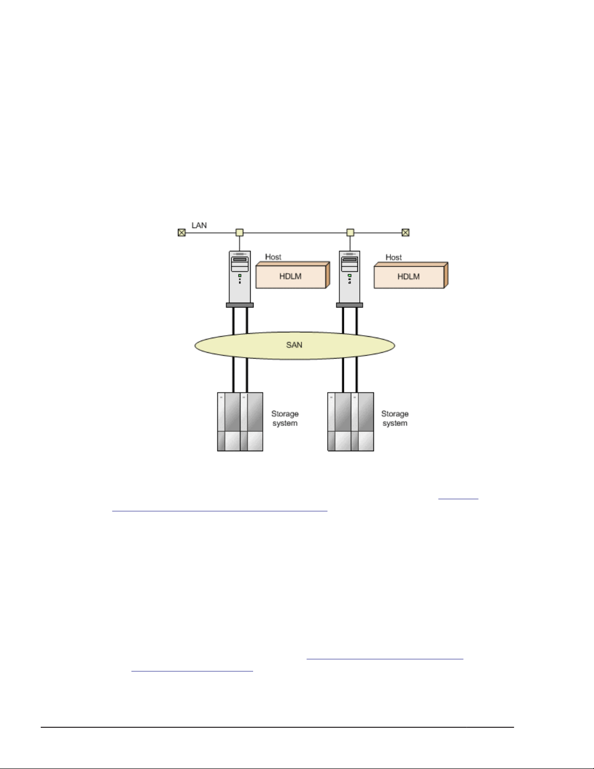
The figure below shows the connections between hosts and storage systems.
A server on which HDLM is installed is called a host.
For details about the storage systems supported by HDLM, see Storage
Systems Supported by HDLM on page 3-4.
HDLM Features
HDLM features include the following:
The ability to distribute a load across multiple paths. This is also known as
load balancing.
When a host is connected to a storage system via multiple paths, HDLM
can distribute the load across all the paths. This prevents one, loaded
down path from affecting the processing speed of the entire system.
For details on load balancing, see
Balancing on page 2-10.
1-2
Figure 1-1 Connections between hosts and storage systems
Distributing a Load Using Load
Overview of HDLM
Hitachi Dynamic Link Manager (for Solaris) User Guide
Page 21

The ability to continue running operations between a host and storage
system, even if there is a failure. This is also known as performing a failover.
When a host is connected to a storage system via multiple paths, HDLM
can automatically switch to another path if there is some sort of failure in
the path that is currently being used. This allows operations to continue
between a host and a storage system.
For details on performing failovers, see
Using Path Switching on page 2-15.
The ability to bring a path that has recovered from an error back online. This
is also known as performing a failback.
If a path is recovered from an error, HDLM can bring that path back
online. This enables the maximum possible number of paths to always be
available and online, which in turn enables HDLM to better distribute the
load across multiple paths.
Failbacks can be performed manually or automatically. In automatic
failback, HDLM automatically restores the route to the active state after
the user has corrected hardware problems in the route.
For details on performing failbacks, see
Failbacks Using Path Switching on page 2-15.
The ability to automatically check the status of any given path at regular
intervals. This is also known as path health checking.
HDLM can easily detect errors by checking the statuses of paths at userdefined time intervals. This allows you to check for any existing path
errors and to resolve them promptly and efficiently.
For details on setting up and performing path health checking, see
Detecting Errors by Using Path Health Checking on page 2-28.
Performing Failovers and Failbacks
Performing Failovers and
Overview of HDLM
Hitachi Dynamic Link Manager (for Solaris) User Guide
1-3
Page 22

1-4
Overview of HDLM
Hitachi Dynamic Link Manager (for Solaris) User Guide
Page 23

2
HDLM Functions
This chapter describes the various functions that are built into HDLM. Before
the function specifications are explained though, this chapter will go into
detail about the HDLM management targets, system configuration, and basic
terms that are necessary to know to effectively operate HDLM. After that, the
rest of the chapter focus on describing all the HDLM functions, including the
main ones: load distribution across paths and path switching.
Devices Managed by HDLM
□
System Configuration
□
LU Configuration
□
Program Configuration
□
Position of the HDLM Driver and HDLM Device
□
Logical Device Files for HDLM Devices
□
Distributing a Load Using Load Balancing
□
Performing Failovers and Failbacks Using Path Switching
□
Intermittent Error Monitoring (Functionality When Automatic Failback Is
□
Used)
Detecting Errors by Using Path Health Checking
□
Distributing a Load by Using the Dynamic I/O Path Control Function
□
Error Management
□
HDLM Functions
Hitachi Dynamic Link Manager (for Solaris) User Guide
2-1
Page 24

Collecting Audit Log Data
□
Integrated HDLM management using Global Link Manager
□
Cluster Support
□
2-2
HDLM Functions
Hitachi Dynamic Link Manager (for Solaris) User Guide
Page 25

Devices Managed by HDLM
Below is a list of devices that can or cannot be managed by HDLM. The
devices that can be managed by HDLM are called HDLM management-target
devices.
HDLM management-target devices:
The following devices are from the storage systems listed in Section What
is HDLM? on page 1-2:
¢
SCSI devices (sd or ssd devices)
¢
Boot disks
¢
Swap devices
¢
Dump devices
#:
If you want to use these disks as HDLM management-target devices,
assign VTOC labels to them. EFI labels are not supported.
Non-HDLM management-target devices:
¢
SCSI devices (sd or ssd devices) other than those of the storage
systems listed in Section What is HDLM? on page 1-2
¢
Built-in disks in a host
¢
Devices other than disks (tape devices, etc.)
¢
Command devices of the storage systems listed in Section
HDLM? on page 1-2 (For example, Hitachi RAID Manager command
devices.)
#
#
#
What is
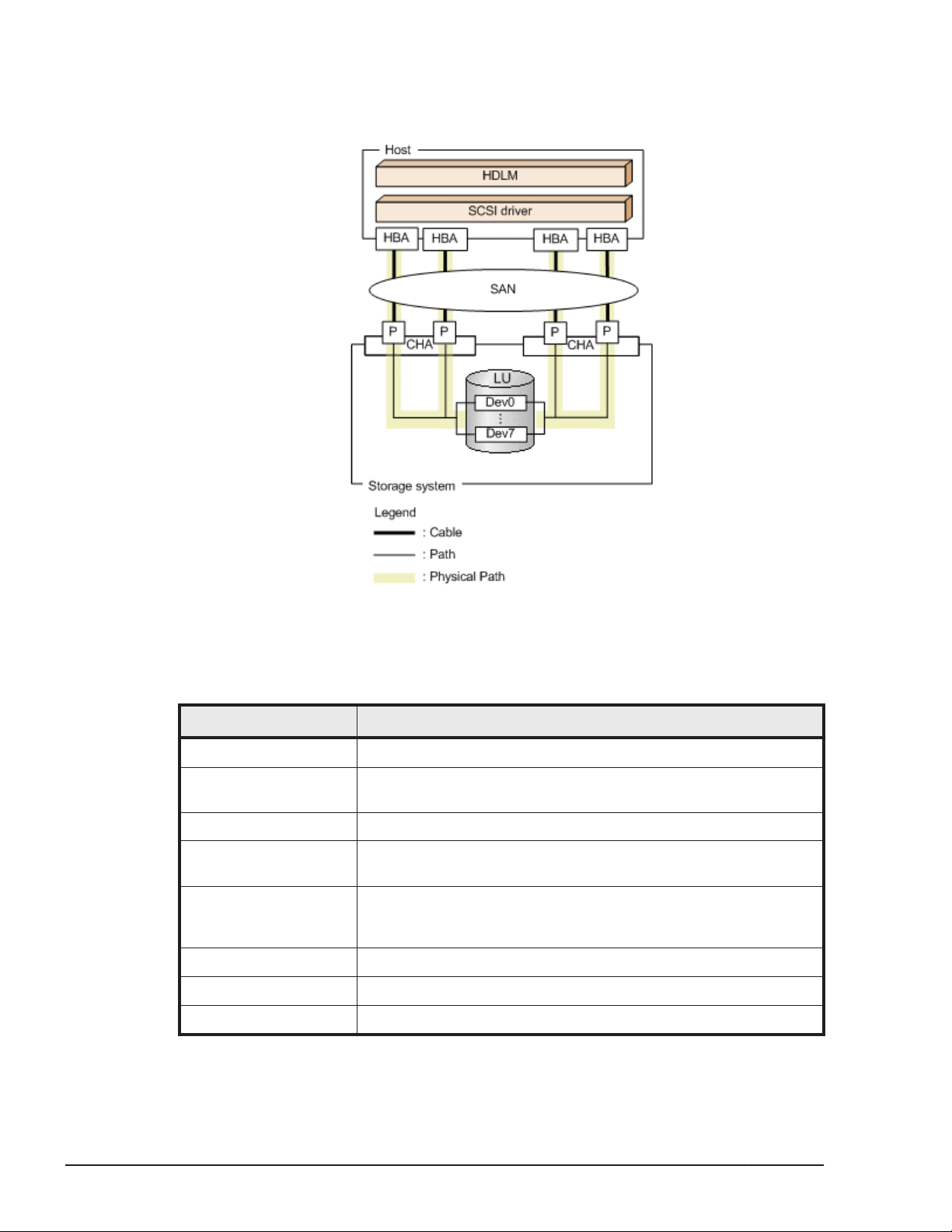
System Configuration
HDLM manages routes between a host and a storage system by using the
SCSI driver (sd or ssd driver). The host and storage systems are connected
using SAN with fiber cables or SCSI cables. The cable port on the host is a
host bus adapter (HBA). The cable port on the storage system is a port (P) on
a channel adapter (CHA).
A logical unit (LU) contained in a storage system is the target of input to, or
output from, the host. You can divide an LU into multiple areas. Each area
after the division is called a Dev. The Dev is equivalent to a slice or partition.
A route that connects a host and an LU is called a physical path, and a route
that connects a host and a Dev is called a path. When an LU has been divided
into multiple Devs, the number of paths set to the LU is equal to the number
that is found by multiplying the number of physical paths by the number of
Devs in the LU.
HDLM assigns an ID to each physical path and manages paths on a physicalpath basis. Because you do not need to be aware of the difference between
physical paths and paths to operate HDLM, the following descriptions might
simply refer to paths, without distinguishing between physical paths and
HDLM Functions
Hitachi Dynamic Link Manager (for Solaris) User Guide
2-3
Page 26
paths. The ID that HDLM assigns to each path (physical path) is called a
AutoPATH_ID. A path is also sometimes called a managed object.
The following figure shows the HDLM system configuration.
Figure 2-1 HDLM System Configuration
The following table lists and describes the HDLM system components.
Table 2-1 HDLM System Components
Components Description
HBA A host bus adapter. This serves as a cable port on the host.
SAN A dedicated network that is used for data transfer between the
host and storage systems
CHA A channel adapter
P A port on a CHA. This serves as a cable port on a storage
system.
LU A logical unit (a logical volume defined on the storage system).
This serves as the target of input or output operations from the
host.
Dev An area (slice or partition) that is created when an LU is divided
Physical path A route that connects a host and an LU
Path A route that connects a host and a Dev
2-4
HDLM Functions
Hitachi Dynamic Link Manager (for Solaris) User Guide
Page 27

LU Configuration
After you have properly installed HDLM, the LU configuration will change as
follows:
Before the installation of HDLM:
The host recognizes that an sd or ssd device is connected to each physical
path.
Thus, a single LU in the storage system is recognized as the same
number of LUs as that of physical paths.
After the installation of HDLM:
An HDLM device that corresponds one-to-one with the Dev in an LU in the
storage system is created above an sd or ssd device.
Thus, from the host, LUs in the storage system are also recognized as one
LU regardless the number of physical paths.
After the installation of HDLM, an LU recognized by a host is called a host LU
(HLU). The areas in a host LU that correspond to the Devs (slice or partition)
in a storage system LU are called host devices (HDev).
On a system using HDLM, the logical device file for the HDLM device is used
to access the target LU instead of the logical device file for the sd or ssd
device.
The logical device files for sd or ssd are deleted by HDLM.
The following figure shows the LU configuration recognized by the host, after
the installation of HDLM.
HDLM Functions
Hitachi Dynamic Link Manager (for Solaris) User Guide
2-5
Page 28
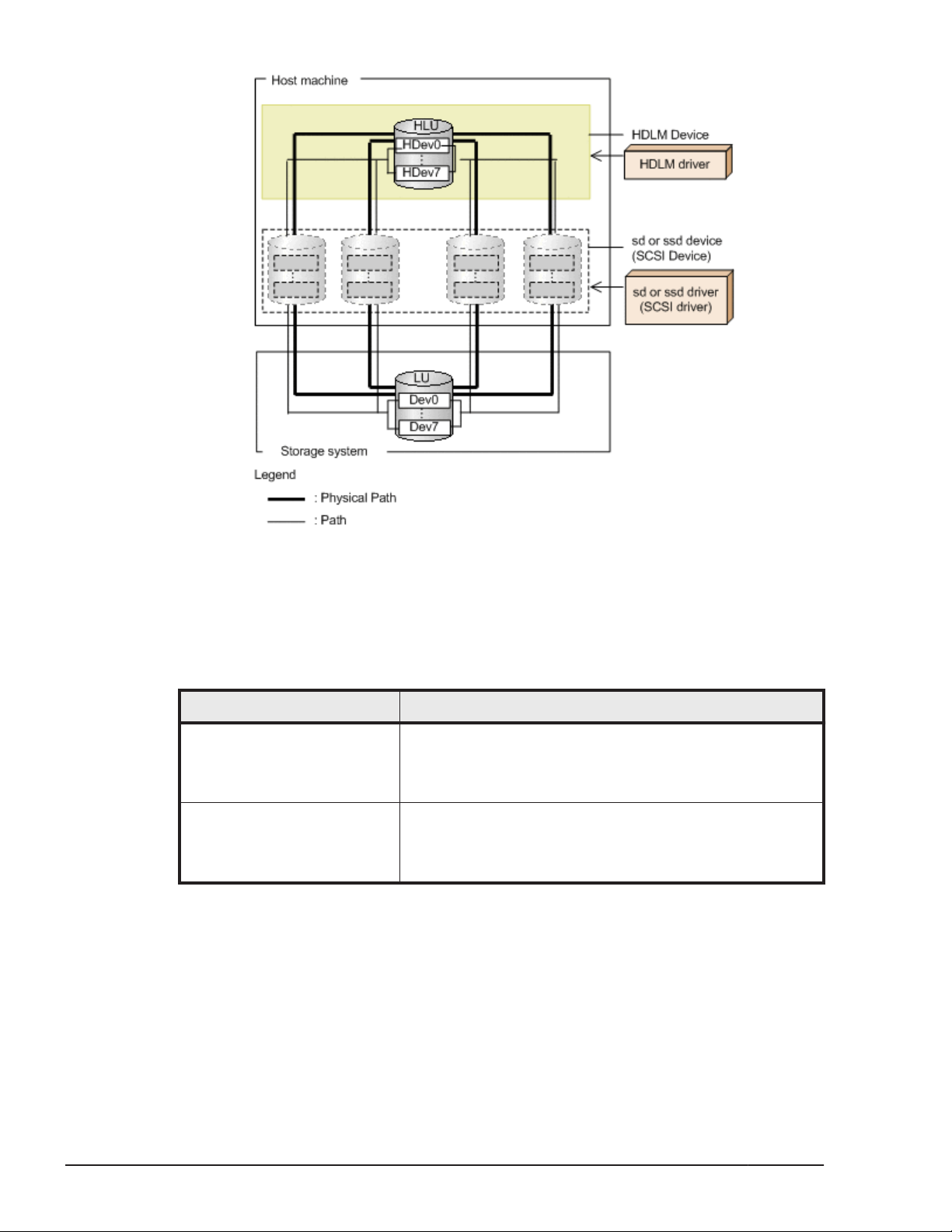
Figure 2-2 LU Configuration Recognized by the Host After the Installation
The following table lists and describes the components recognized by the
host.
Table 2-2 Components Recognized by the Host
Components Description
HLU An LU that the host recognizes via the HDLM driver. It is
HDev A Dev (a slice or partition) in an LU that the host
Program Configuration
HDLM is actually a combination of several programs. Because each program
corresponds to a specific HDLM operation, it is important to understand the
name and purpose of each program, along with how they are all interrelated.
of HDLM
called a host LU. No matter how many physical paths
exist, one host LU is recognized for one LU in the storage
system.
recognizes via the HDLM driver. It is called a host device.
No matter how many physical paths exist, one host
device is recognized for one Dev in the storage system.
2-6
The following figure shows the configuration of the HDLM programs.
HDLM Functions
Hitachi Dynamic Link Manager (for Solaris) User Guide
Page 29
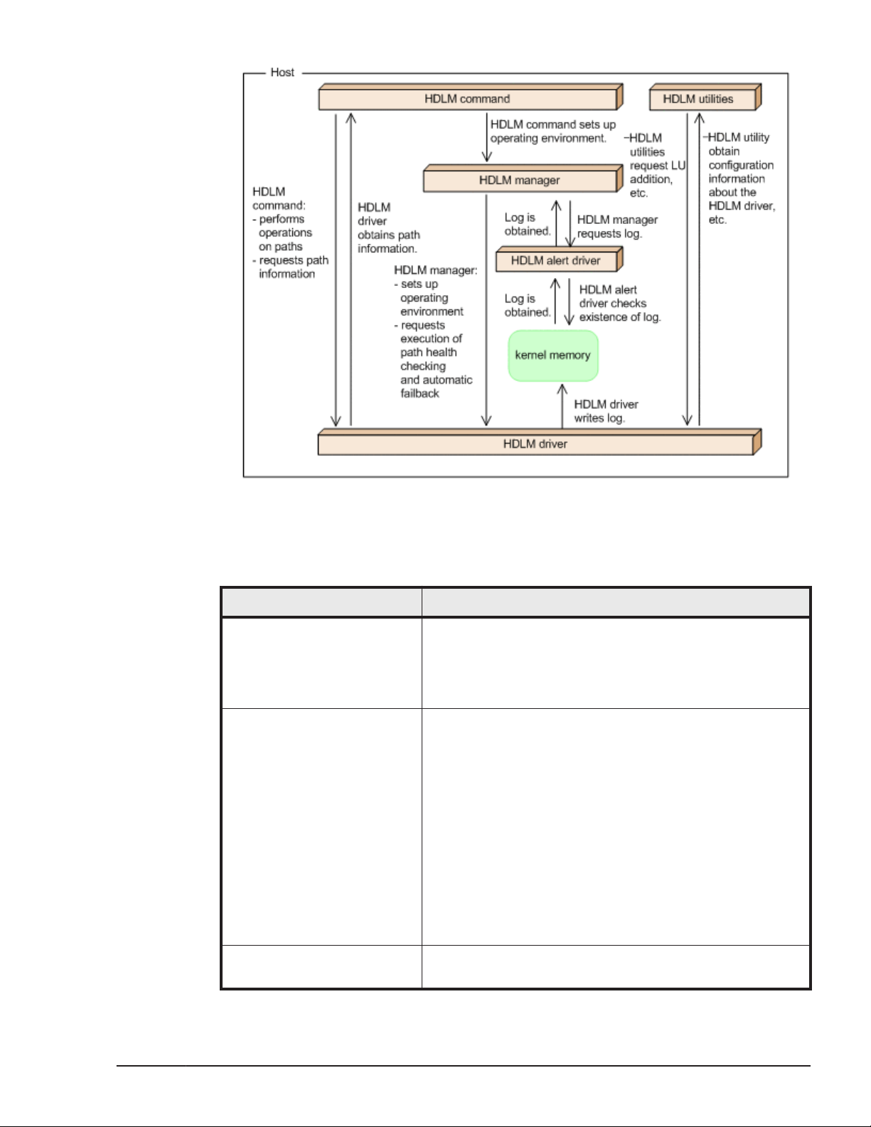
Figure 2-3 Configuration of the HDLM Programs
The following table lists and describes the functions of these programs.
Table 2-3 Function of HDLM Programs
Program name Functions
HDLM command Provides the dlnkmgr command, which enables you to:
• Manage paths
• Display error information
• Set up the HDLM operating environment
HDLM utility Provides the HDLM utility, which enables you to:
• Collect error information
• Add a new LU and delete an existing LU
(reconfiguring an HDLM device dynamically)
• Create an HDLM driver configuration definition file (/
kernel/drv/dlmfdrv.conf)
• Create a correspondence table of logical device files
when migrating to HDLM 6.5.1
• Support the creation of a VxVM configuration file
• The unattended installation of HDLM
• Install Hitachi Command Suite Common Agent
Component
HDLM manager Provides the HDLM manager, which enables you to:
• Configure the HDLM operating environment
HDLM Functions
Hitachi Dynamic Link Manager (for Solaris) User Guide
2-7
Page 30

Program name Functions
• Request path health checks and automatic failbacks
to be performed
• Collect error log data
HDLM alert driver Reports the log information collected by the HDLM driver
to the HDLM manager. The driver name is dlmadrv.
HDLM driver Controls all the HDLM functions, manages paths, and
detects errors. The HDLM driver consists of the following:
• Core logic component
Controls the basic functionality of HDLM.
• Filter component
Sends and receives I/O data. The driver name is
dlmfdrv.
• HDLM nexus driver
Performs operations such as reserving controller
numbers for logical device files of the HDLM device,
and managing HDLM driver instances for each HBA
port. The driver name is dlmndrv.
Position of the HDLM Driver and HDLM Device
The HDLM driver is positioned above the SCSI driver. Each application on the
host uses the HDLM device (logical device file) created by HDLM, to access
LUs in the storage system. The following figure shows the positions of the
HDLM driver and HDLM devices.
2-8
HDLM Functions
Hitachi Dynamic Link Manager (for Solaris) User Guide
Page 31
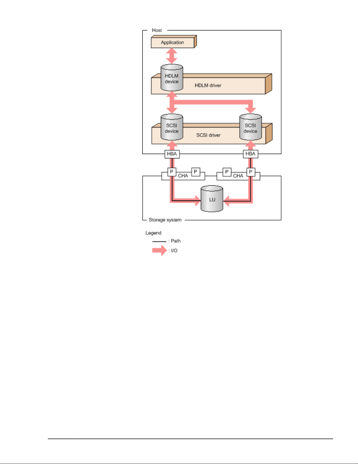
Figure 2-4 Position of the HDLM Driver and HDLM Devices
Logical Device Files for HDLM Devices
When you install HDLM, a logical device file to be used by HDLM will be
created for each LU on a per-Dev (slice) basis. Setting this logical device file
name in an application, such as volume management software, enables the
application to access an LU by using the HDLM function.
The logical device files existing before HDLM installation (the logical device
files of an sd or ssd) will be deleted.
The following explains the names and locations of the logical device files for
HDLM devices
Logical device file names for HDLM devices
The logical device file name of an HDLM device is a changed version of
the controller number of the logical device file name of the sd or ssd
device. For example, let us assume that an LU has two physical paths,
HDLM Functions
Hitachi Dynamic Link Manager (for Solaris) User Guide
2-9
Page 32

and for one of the Dev (slices) in that LU, the corresponding logical device
file names of the sd or ssd devices are c2t1d1s0 and c3t2d1s0. In this
case, when you install HDLM, these logical device files will be deleted.
Then, a logical device file that has a different controller number, such as
c4t1d1s0, is created for the HDLM device.
The following explains each part of the logical device file name format
cUtXdYsZ:
U
The controller number reserved by HDLM using a nexus driver
X
The target ID or WWN (World Wide Name) of the sd or ssd device that
corresponds to the HDLM device
Y
The LUN of the sd or ssd device that corresponds to the HDLM device
Z
The device slice number of the sd or ssd device that corresponds to
the HDLM device
Note
In Solaris 9, Solaris 10, or Solaris 11, if EFI labels are set for LUs, the
HDLM logical device name, which represents the entire LU, will be in
the cUtXdY format.
Locations of logical device files for HDLM devices
Block logical device files for HDLM devices are created in /dev/dsk.
Character logical device files for HDLM devices are created in /dev/rdsk.
Distributing a Load Using Load Balancing
When the system contains multiple paths to a single LU, HDLM can distribute
the load across the paths by using multiple paths to transfer the I/O data.
This function is called load balancing, and it prevents a single, heavily loaded
path from affecting the performance of the entire system.
Note that some I/O operations managed by HDLM can be distributed to each
path, while others cannot. Therefore, even though load balancing function is
used, I/O operations might not be equally allocated to each path.
Figure 2-5 Flow of I/O Data When the Load Balancing Function Is Not Used on
page 2-11 shows the flow of I/O data when the load balancing function is
not used. Figure 2-6 Flow of I/O Data When the Load Balancing Function Is
Used on page 2-12 shows the flow of I/O data when the load balancing
function is used. Both figures show an example of an I/O being issued for the
same LU from multiple applications.
2-10
HDLM Functions
Hitachi Dynamic Link Manager (for Solaris) User Guide
Page 33
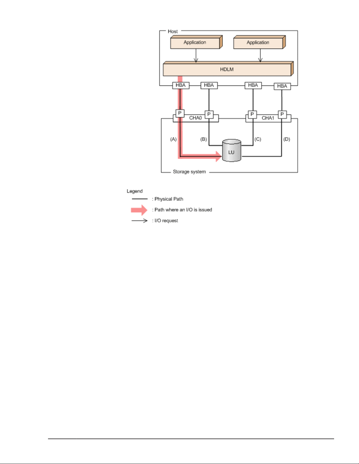
Figure 2-5 Flow of I/O Data When the Load Balancing Function Is Not
Used
When the load balancing function is not used, I/O operations converge onto a
single path (A). The load on that one physical path (A) will cause a
bottleneck, which might cause problems with system performance.
HDLM Functions
Hitachi Dynamic Link Manager (for Solaris) User Guide
2-11
Page 34

Figure 2-6 Flow of I/O Data When the Load Balancing Function Is Used
When the load balancing function is used, I/O operations are distributed via
multiple physical paths (A, B, C, and D). This helps to prevent problems with
system performance and helps prevent bottlenecks from occurring.
Paths to Which Load Balancing Is Applied
This section describes, for each type of storage system, the paths to which
the load balancing function is applied.
When Using the Thunder 9500V Series, or Hitachi AMS/WMS series
When HDLM performs load balancing, it differentiates between load balancing
among owner paths and among non-owner paths. An owner path is a path
that passes through the owner controller for a target LU. This path is set on
the owner controller of the storage system LU. Because the owner controller
varies depending on the LU, the owner path also varies depending on the LU.
A non-owner path is a path that uses a CHA other than the owner controller
(a non-owner controller). The paths to be used are selected, in the order of
owner paths and non-owner paths. To prevent performance in the entire
system from deteriorating, HDLM does not perform load balancing between
owner paths and non-owner paths. When some owner paths cannot be used
due to a problem such as a failure, load balancing is performed among the
2-12
HDLM Functions
Hitachi Dynamic Link Manager (for Solaris) User Guide
Page 35

remaining usable owner paths. When all owner paths cannot be used, load
balancing is performed among the non-owner paths.
For the example in Figure 2-7 Overview of Load Balancing on page 2-13,
suppose that in the owner controller of LU0 is CHA0. When the LU is
accessed, the load is balanced between the two physical paths A and B, which
are both owner paths. When one of the paths (A) cannot be used, then the
LU is accessed from the only other owner physical path (B). When both of the
owner physical paths (A and B) cannot be used, the load is then balanced
between two other, non-owner physical paths (C and D).
Figure 2-7 Overview of Load Balancing
When Using Other Than the Thunder 9500V Series and Hitachi AMS/WMS Series
All online paths are owner paths. Therefore, for the example in Figure 2-6
Flow of I/O Data When the Load Balancing Function Is Used on page 2-12,
the load is balanced among the four physical paths A, B, C, and D. If one of
the physical paths were to become unusable, the load would be balanced
among the three, remaining physical paths.
Note:
Load balancing is performed for the following storage systems:
¢
Lightning 9900V series
¢
Hitachi USP series
¢
Universal Storage Platform V/VM series
¢
Virtual Storage Platform series
¢
VSP G1000 series
HDLM Functions
Hitachi Dynamic Link Manager (for Solaris) User Guide
2-13
Page 36

¢
Hitachi AMS2000 series
¢
Hitachi SMS series
¢
HUS100 series
¢
HUS VM
#: This storage system applies when the dynamic I/O path control
function is disabled.
Load Balancing Algorithms
HDLM has the following six load balancing algorithms:
• The Round Robin algorithm
• The Extended Round Robin algorithm
• The Least I/Os algorithm
• The Extended Least I/Os algorithm
• The Least Blocks algorithm
• The Extended Least Blocks algorithm
The above algorithms are divided into two categories, which differ in their
processing method. The following describes both of these processing
methods:
#
#
#
The Round Robin, Least I/Os, and Least Blocks algorithms
These algorithms select which path to use every time an I/O is issued.
The path that is used is determined by the following:
¢
Round Robin
The paths are simply selected in order from among all the connected
paths.
¢
Least I/Os
The path that has the least number of I/Os being processed is
selected from among all the connected paths.
¢
Least Blocks
The path that has the least number of I/O blocks being processed is
selected from among all the connected paths.
The Extended Round Robin, Extended Least I/Os, and Extended Least Blocks
algorithms
These algorithms determine which path to allocate based on whether the
I/O to be issued is sequential with the immediately preceding I/O.
If the I/O is sequential with the previous I/O, the path to which the
previous I/O was distributed will be used. However, if a specified number
of I/Os has been issued to a path, processing switches to the next path.
If the I/O is not sequential with the previous I/O, these algorithms select
the path to be used each time an I/O request is issued.
2-14
¢
Extended Round Robin
Hitachi Dynamic Link Manager (for Solaris) User Guide
HDLM Functions
Page 37

The paths are simply selected in order from among all the connected
paths.
¢
Extended Least I/Os
The path that has the least number of I/Os being processed is
selected from among all the connected paths.
¢
Extended Least Blocks
The path that has the least number of I/O blocks being processed is
selected from among all the connected paths.
The following table lists and describes the features of the load balancing
algorithms.
Table 2-4 Features of the Load Balancing Algorithms
Algorithm type Algorithm features
•
Round Robin
• Least I/Os
• Least Blocks
• Extended Round
Robin
• Extended Least I/Os
• Extended Least
Blocks
#
These types of algorithms are most effective when a lot of
discontinuous, non-sequential I/Os are issued.
If the I/O data is from something like a read request and is
generally sequential with the previous I/Os, an improvement
in reading speed can be expected due to the storage system
cache functionality. These types of algorithms are most
effective when a lot of continuous, sequential I/Os are issued.
#
Some I/O operations managed by HDLM can be distributed across all,
available paths, and some cannot. Thus, you should be aware that even if
you specify the Round Robin algorithm, some of the I/O operations will
never be issued uniformly across all the given paths.
The default algorithm is the Extended Least I/Os algorithm, which is set when
HDLM is first installed. When an upgrade installation of HDLM is performed,
the algorithm that is currently being used is inherited.
Select the load balancing algorithm most suitable for the data access patterns
of your system environment. However, if there are no recognizable data
access patterns, we recommend using the default algorithm, the Extended
Least I/Os algorithm.
You can specify the load balancing function by the dlnkmgr command's set
operation. For details on the set operation, see
set (Sets Up the Operating
Environment) on page 6-17.
Performing Failovers and Failbacks Using Path Switching
When the system contains multiple paths to an LU and an error occurs on the
path that is currently being used, HDLM can switch to another functional
path, so that the system can continue operating. This is called a failover.
HDLM Functions
Hitachi Dynamic Link Manager (for Solaris) User Guide
2-15
Page 38

If a path in which an error has occurred recovers from the error, HDLM can
then switch back to that path. This is called a failback.
Two types of failovers and failbacks are available:
• Automatic failovers and failbacks
• Manual failovers and failbacks
Failovers and failbacks switch which path is being used and also change the
statuses of the paths. A path status is either online or offline. An online status
means that the path can receive I/Os. On the other hand, an offline status
means that the path cannot receive I/Os. A path will go into the offline status
for the following reasons:
• An error occurred on the path.
• A user executed the HDLM command's offline operation.
For details on the offline operation, see
offline (Places Paths Offline) on
page 6-6.
For details on path statuses and the transitions of those statuses, see
Status Transition on page 2-19.
Notes
Switching a reserved path might take several seconds. A reserved path is
switched in the following cases:
¢
The reserved path is placed offline.
¢
An owner path is placed online when a path has been reserved while
only non-owner paths are online.
Automatic Path Switching
This section describes the automatic failover and automatic failback functions
that automatically switch paths.
Automatic Failovers
If you detect an error in a path being used, you can keep operating the
system by changing the path state to offline, and using other online paths.
This function is called automatic failover. Automatic failovers can be used for
the following levels of errors:
Critical
A fatal error that might stop the system.
Path
2-16
Error
A high-risk error, which can be avoided by performing a failover or some
other countermeasure.
For details on error levels, see Filtering of Error Information on page 2-32.
When the Thunder 9500V series, or Hitachi AMS/WMS series is being used,
HDLM will select the path to be used next from among the various paths that
access the same LU, starting with owner paths, and then non-owner paths.
HDLM Functions
Hitachi Dynamic Link Manager (for Solaris) User Guide
Page 39

For example, in Figure 2-8 Path Switching on page 2-17, the owner
controller of LU is CHA0, and access to the LU is made only via the physical
path (A). After the access path is placed offline, the first candidate for the
switching destination is the physical path (B) and the second candidate is the
physical path (C or D).
When the Lightning 9900V Series, Hitachi USP Series, Universal Storage
Platform V/VM Series, Virtual Storage Platform Series, VSP G1000 Series,
Hitachi AMS2000 Series#, Hitachi SMS Series#, HUS100 Series#, or HUS VM
is being used, all the paths are owner paths. This means that all the paths
that are accessing the same LU are possible switching destinations. For
example, in
using only the one physical path (A). However, after that path is placed
offline, the switching destination can come from any of the other three
physical paths (B, C, or D).
#
This storage system applies when the dynamic I/O path control function is
disabled.
Paths are switched in units of physical paths. Therefore, if an error occurs in a
path, HDLM switches all the other paths that run through the same physical
path.
Figure 2-8 Path Switching on page 2-17, the LU is accessed
Figure 2-8 Path Switching
HDLM Functions
Hitachi Dynamic Link Manager (for Solaris) User Guide
2-17
Page 40

Automatic Failbacks
When a path recovers from an error, HDLM can automatically place the
recovered path back online. This function is called the automatic failback
function.
In order to use the automatic failback function, HDLM must already be
monitoring error recovery on a regular basis.
When the Thunder 9500V series, or Hitachi AMS/WMS series is being used,
HDLM selects the path to use from online owner paths, and then from online
non-owner paths. Therefore, if an owner path recovers from an error and
HDLM automatically places the recovered path online while any non-owner
path is in use, the path in use will be switched to the recovered owner path.
When the Lightning 9900V Series, Hitachi USP Series, Universal Storage
Platform V/VM Series, Virtual Storage Platform Series, VSP G1000 Series,
Hitachi AMS2000 Series#1, Hitachi SMS Series#1, HUS100 Series#1, or HUS
VM is being used, all the paths are owner paths. Therefore, if an owner path
recovers from an error and HDLM automatically places the recovered path
online, the path in use will not be switched to the recovered owner path.
When intermittent errors#2 occur on paths and you are using the automatic
failback function, the path status might frequently alternate between the
online and offline statuses. In such a case, because the performance of I/Os
will most likely decrease, if there are particular paths in which intermittent
errors might be occurring, we recommend that you set up intermittent error
monitoring so you can detect these paths, and then remove them from those
subject to automatic failbacks.
You can specify the automatic failback function or intermittent error
monitoring by the dlnkmgr command's set operation. For details on the set
operation, see
#1
This storage system applies when the dynamic I/O path control function is
disabled.
#2
An intermittent error means an error that occurs irregularly because of,
for example, a loose cable connection.
set (Sets Up the Operating Environment) on page 6-17.
Manual Path Switching
You can switch the status of a path by manually placing the path online or
offline. Manually switching a path is useful, for example, when system
maintenance needs to be done.
You can manually place a path online or offline by doing the following:
• Execute the dlnkmgr command's online or offline operation.
For details on the online operation, see
page 6-12. For details on the offline operation, see offline (Places
Paths Offline) on page 6-6.
online (Places Paths Online) on
2-18
HDLM Functions
Hitachi Dynamic Link Manager (for Solaris) User Guide
Page 41

However, if there is only one online path for a particular LU, that path cannot
be manually switched offline. Also, a path with an error that has not been
recovered from yet cannot be switched online.
HDLM uses the same algorithms to select the path that will be used next,
regardless of whether automatic or manual path switching is used.
When the Thunder 9500V series, or Hitachi AMS/WMS series is being used,
HDLM selects the switching destination path from owner paths and then from
non-owner paths. When the Lightning 9900V Series, Hitachi USP Series,
Universal Storage Platform V/VM Series, Virtual Storage Platform Series, VSP
G1000 Series, Hitachi AMS2000 Series#, Hitachi SMS Series#, HUS100
Series#, or HUS VM is being used, all paths that access the same LU are
candidates for the switching destination path.
Paths are switched in units of physical paths. Therefore, if an error occurs in a
path, all the other paths that run through the same physical path are
switched.
Executing the online operation places the offline path online. For details on
the online operation, see
the path status is changed to online, HDLM selects the path to use in the
same way as for automatic path switching. When the Thunder 9500V series,
or Hitachi AMS/WMS series is being used, HDLM selects the path to use from
online owner paths, and then from online non-owner paths. When the
Lightning 9900V Series, Hitachi USP Series, Universal Storage Platform V/VM
Series, Virtual Storage Platform Series, VSP G1000 Series, Hitachi AMS2000
Series#, Hitachi SMS Series#, HUS100 Series#, or HUS VM is being used,
because all the paths are owner paths, the path to use is not switched even if
you change the path status to online.
online (Places Paths Online) on page 6-12. After
#
This storage system applies when the dynamic I/O path control function is
disabled.
Path Status Transition
Each of the online and offline statuses described in Performing Failovers and
Failbacks Using Path Switching on page 2-15 is further subdivided into
several statuses. The path statuses (the online path statuses and offline path
statuses) are explained below.
The Online Path Status
The online path statuses are as follows:
• Online
I/Os can be issued normally.
• Online(E)
An error has occurred in the path. Also, none of the paths that access the
same LU are in the Online status.
HDLM Functions
Hitachi Dynamic Link Manager (for Solaris) User Guide
2-19
Page 42

If none of the paths accessing a single LU are in the Online status, one of
the paths will be changed to the Online(E) status. All the paths that
access the same LU will not be in the offline statuses. This ensures access
to the LU.
The text (E) of Online(E) indicates the error attribute, which indicates that
an error occurred in the path.
•
Online(S)
The paths to the primary volume (P-VOL) in the HAM environment have
recovered from an error, but I/O to the P-VOL is suppressed.
•
Online(D)
The paths to the primary volume (P-VOL) in an HAM environment have
recovered from an error, but I/O to the P-VOL is suppressed. If an error
occurs in all the paths to a secondary volume (S-VOL), the status of the
P-VOL paths will be automatically changed to the Online status. To
change the status to the Online(D) status, specify the -dfha parameter
for the HDLM command's online operation.
#
The status changes to this status when using HAM (High Availability
Manager).
The Offline Path Status
#
#
The offline path statuses are as follows:
• Offline(C)
The status in which I/O cannot be issued because the offline operation
was executed. For details on the offline operation, see offline (Places
Paths Offline) on page 6-6.
The (C) indicates the command attribute, which indicates that the path
was placed offline by using the command.
• Offline(E)
The status indicating that an I/O could not be issued on a given path,
because an error occurred on the path.
The (E) in Offline(E) indicates the error attribute, which indicates that an
error occurred in the path.
Status Transitions of a Path
The following figure shows the status transitions of a path.
2-20
HDLM Functions
Hitachi Dynamic Link Manager (for Solaris) User Guide
Page 43

Figure 2-9 Path Status Transitions
Legend:
Online operation: Online operation performed by executing the dlnkmgr
command's online operation.
Offline operation: Offline operation performed by executing the dlnkmgr
command's offline operation.
#1
When no Online or Offline(E) paths exist among the paths that access the
same LU.
#2
When the following conditions are satisfied, a path that has been
determined to have an intermittent error also becomes subject to
automatic failback:
¢
All the paths connected to an LU are Online(E), Offline(E), or
Offline(C).
¢
All the paths connected to an LU have been determined to have an
intermittent error.
¢
The processing of continuous I/O issued to an LU is successful.
#3
When an Online or Offline(E) path exists among the paths that access the
same LU.
HDLM Functions
Hitachi Dynamic Link Manager (for Solaris) User Guide
2-21
Page 44

#4
One of the Offline(E) paths is changed to the Online(E) path.
#5
When an Offline(E) path exists among the paths that access the same LU.
Figure 2-10 Path Status Transitions (P-VOL in HAM environment)
Legend:
Online operation: Online operation performed by executing the dlnkmgr
command's online operation.
Offline operation: Offline operation performed by executing the dlnkmgr
command's offline operation.
#1
Also when an error occurs in all the paths to an S-VOL in the Online(D)
status.
#2
When I/O operations are processed on an S-VOL.
The last available online path for each LU cannot be placed offline by
executing the offline operation. This ensures access to the LU. For details
on the offline operation, see offline (Places Paths Offline) on page 6-6.
If none of the paths accessing a single LU are in the Online status, one of the
paths will be changed to the Online(E) status.
If you are using automatic failback, when the path recovers from an error,
HDLM automatically places the path online.
2-22
HDLM Functions
Hitachi Dynamic Link Manager (for Solaris) User Guide
Page 45

When you are using intermittent error monitoring, the path in which the
intermittent error occurred is not automatically placed online even when the
path recovers from the error. In such a case, place the path online manually.
Note
If there is a path failure immediately after a path is placed offline by using
the dlnkmgr command, Offline(C) might change to Offline(E). If an offline
operation was performed, wait for a fixed period of time (about 2
minute), check the path status by using the dlnkmgr command, and
make sure that the status has changed to Offline(C). If it is Offline(E),
retry the offline operation.
Intermittent Error Monitoring (Functionality When Automatic Failback Is Used)
An intermittent error means an error that occurs irregularly because of, for
example, a loose cable connection. I/O performance might decrease while an
automatic failback is being performed to repair an intermittent error. This is
because the automatic failback operation is being performed repeatedly
(because the intermittent error keeps occurring). To prevent this from
happening, HDLM can automatically remove the path where an intermittent
error is occurring from the paths that are subject to automatic failbacks. This
process is called intermittent error monitoring.
We recommend that you use intermittent error monitoring along with the
automatic failback function.
A path in which an error occurs a specified number of times within a specified
interval is determined to have an intermittent error. The path where an
intermittent error occurs has an error status until the user chooses to place
the path back online. Automatic failbacks are not performed for such paths.
This status is referred to as the not subject to auto failback status.
Checking Intermittent Errors
You can check the paths in which intermittent errors have occurred by
viewing the execution results of the HDLM command's view operation.
For details on the view operation, see
6-34.
view (Displays Information) on page
Setting Up Intermittent Error Monitoring
When you use the intermittent error function, you can enable or disable the
function. If you enable the function, specify the monitoring conditions: the
error monitoring interval, and the number of times that the error is to occur.
If an error occurs in a path the specified number of times within the specified
error monitoring interval, the system determines that the path has an
intermittent error. For example, if you specify 30 for the error monitoring
interval and 3 for the number of times that the error is to occur, the path is
HDLM Functions
Hitachi Dynamic Link Manager (for Solaris) User Guide
2-23
Page 46

determined to have an intermittent error if an error occurs 3 or more times in
30 minutes.
You can set up intermittent error monitoring by executing the dlnkmgr
command's set operation.
Intermittent error monitoring can be used only when automatic failback has
already been enabled. The values that can be specified for intermittent error
monitoring depend on the values specified for automatic failbacks. For details
on how to specify the settings, see
on page 6-17.
Intermittent Error Monitoring Actions
Intermittent error monitoring is performed on each path, and it automatically
starts as soon as a path is recovered from an error by using the automatic
failback function.
This subsection describes the actions for intermittent error monitoring in the
following cases:
• When an intermittent error occurs
• When an intermittent error does not occur
• When the conditions for an intermittent error to occur are changed during
error monitoring
set (Sets Up the Operating Environment)
When an Intermittent Error Occurs
When an error occurs on a path a specified number of times within a specified
interval, the error monitoring will finish and the path is determined to have
an intermittent error, upon which the path is removed from those subject to
automatic failbacks. The path that is removed will remain in the error status
until the online operation is performed. However, if the path satisfies certain
conditions (see
subject to automatic failbacks and change to the Online status.
The figure below shows the action taken when an intermittent error is
assumed to have occurred on the path. For this example, the path is
determined to have an intermittent error when the error occurs 3 or more
times within 30 minutes. The events that occur are described by using the
time arrows.
Figure 2-9 Path Status Transitions on page 2-21), it will be
2-24
HDLM Functions
Hitachi Dynamic Link Manager (for Solaris) User Guide
Page 47
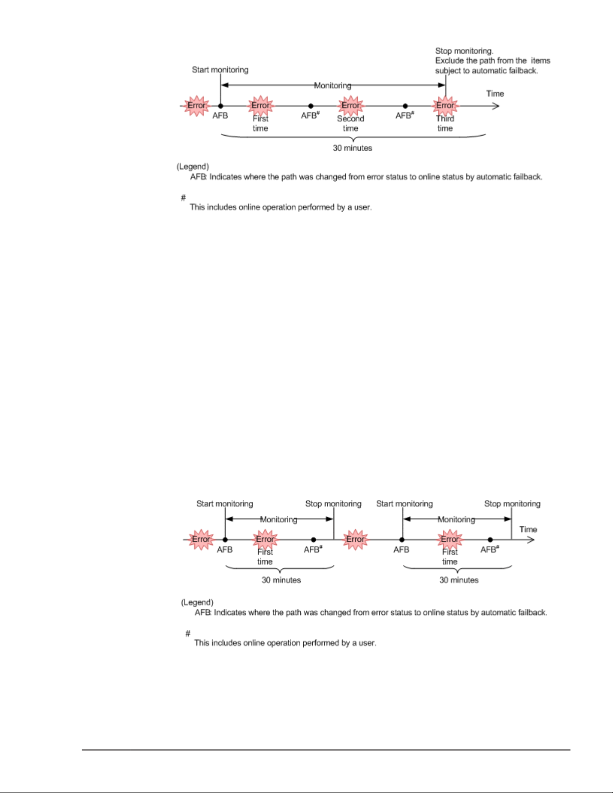
Figure 2-11 Action What Will Happen When an Intermittent Error Occurs
on a Path
When an Intermittent Error Does Not Occur
If an error does not occur in the path the specified number of times within
the specified interval, the system determines that the path does not have an
intermittent error. In such a case, the error monitoring will finish when the
specified error-monitoring interval finishes, upon which the number of errors
is reset to 0. If an error occurs on the path again at a later time, error
monitoring will resume when the path is recovered from the error via an
automatic failback.
If it takes a long time for an error to occur, an intermittent error can be more
easily detected by increasing the error-monitoring interval or by decreasing
the number of times that the error needs to occur.
The figure below shows the action taken when an intermittent error is
assumed not to have occurred on the path. For this example, the path is
determined to have an intermittent error if the error occurs three or more
times in 30 minutes. The events that occur are described by using the time
arrows.
Figure 2-12 What Will Happen When an Intermittent Error Does Not Occur
on a Path
HDLM Functions
Hitachi Dynamic Link Manager (for Solaris) User Guide
2-25
Page 48

As shown in Figure 2-12 What Will Happen When an Intermittent Error Does
Not Occur on a Path on page 2-25, normally, the count for the number of
times that an error occurs is started after the path is first recovered from an
error by using the automatic failback function. However, if all the paths
connected to the LU are in the Offline(E), Online(E), or Offline(C) status
(which is due to the disconnection of the paths or some other reason), the
paths will not be recovered and put back online by using the automatic
failback function. If I/O are continuously issued to such a LU, the number of
times that the error is to occur might be counted even if the path is not
placed online. If the number of times that the error occurs reaches the
specified value, the path is determined to have an intermittent error. In such
a case, remove the cause of the error, and then manually place the path
online.
When the Conditions for an Intermittent Error Are Changed During Error
Monitoring
When the conditions for an intermittent error are changed during error
monitoring, the number of errors and the amount of time that has passed
since the error monitoring started are both reset to 0. As such, the error
monitoring will not finish, and it will start over by using the new conditions.
If the conditions are changed while error monitoring is not being performed,
error monitoring will start up again and use the updated conditions after any
given path is recovered from an error by performing an automatic failback.
The figure below shows the action taken when the conditions for an
intermittent error are changed during intermittent error monitoring. For this
example, the conditions have been changed from 3 or more errors in 30
minutes, to 3 or more errors in 40 minutes. The events that occur are
described by using the time arrows.
Figure 2-13 What Will Happen When Conditions Are Changed During Error
Monitoring
2-26
HDLM Functions
Hitachi Dynamic Link Manager (for Solaris) User Guide
Page 49

When a User Changes the Intermittent Error Information
The following might be reset when a user changes any of the values set for
the intermittent error or the path status: the number of errors that have
already been counted during error monitoring, the amount of time that has
passed since error monitoring has started, and the information about whether
an intermittent error has occurred. Table 2-5 When Effects of a User
Changing the Intermittent Error Information on page 2-27 lists whether the
above items are reset.
If you want to check whether intermittent error monitoring is being
performed for the path, check the IEP item displayed when the dlnkmgr
command's view -path operation is executed with the -iem parameter. If a
numerical value of 0 or greater is displayed in the above items, then
intermittent error monitoring is being performed.
Table 2-5 When Effects of a User Changing the Intermittent Error
Information
Changing the
intermittent error
monitoring settings
Changing the
automatic failback
settings
Number of
errors and time
User operation
passed since
error
monitoring
started
Turning off Reset
Changing the conditions for
an intermittent error while
intermittent error monitoring
is being performed
Turning intermittent error
monitoring on by executing
the set operation, (but not
changing the conditions)
while intermittent error
monitoring is being
performed
Changing the conditions for
an intermittent error outside
the intermittent error
monitoring
Turning off Reset Reset
#2
Reset
(Not applicable)
(Not counted.)
Information
about paths
not subject to
automatic
failback
#1
Reset
Inherited
Inherited
Changing the path
status
Hitachi Dynamic Link Manager (for Solaris) User Guide
Taking the path Offline(C) Reset Reset
Placing the path Online
while intermittent error
monitoring is not being
performed
Placing the path Online
while intermittent error
(Not applicable)
(Not counted.)
Inherited (Not applicable)
Reset
HDLM Functions
2-27
Page 50

Number of
errors and time
User operation
monitoring is being
performed
Restarting the HDLM manager
Restarting the host Reset Reset
passed since
error
monitoring
started
#3
Reset
Information
about paths
not subject to
automatic
failback
If a path has
been removed
from the paths
subject to
automatic
monitoring, that
path is no
longer
monitored.
Inherited
#1
When you disable the intermittent error monitoring function, information
about paths not subject to automatic failback will be reset. If you do not
want to reset the information about paths not subject to automatic
failback when you turn the intermittent error monitoring function off,
change the target paths to Offline(C).
#2
The number of errors and the time since monitoring started is reset to 0,
and then monitoring restarts in accordance with the changed monitoring
conditions.
#3
The number of errors and the time since monitoring started is reset to 0,
and then monitoring restarts at the time the HDLM manager starts.
Detecting Errors by Using Path Health Checking
HDLM can check the status of paths to which I/Os are not issued, at regular
intervals, and detect errors. This function is called path health checking.
Without path health checking, an error is not detected unless I/O is issued
because the system only checks the path status when I/O is issued. With
path health checking, however, the system checks the status of online paths
at regular intervals regardless of whether I/O is issued. If an error is detected
in a path, the path health checking function switches the status of that path
to Offline(E) or Online(E). You can use the dlnkmgr command's view
operation to check the path error.
For example, in a normal state, I/O is not issued on the paths of the standby
host in the cluster configuration or on the non-owner paths (that is, some of
the paths that access the Thunder 9500V Series, or Hitachi AMS/WMS series
storage system). Because of this, for the standby host or for a host
2-28
HDLM Functions
Hitachi Dynamic Link Manager (for Solaris) User Guide
Page 51

connected to non-owner paths, we recommend that you use path health
checking to detect errors. This enables the system to use the most up-to-date
path-status information when selecting the next path to use.
You can configure path health checking by executing the dlnkmgr command's
set operation. For details on the set operation, see set (Sets Up the
Operating Environment) on page 6-17.
Distributing a Load by Using the Dynamic I/O Path Control Function
The result of using HDLM load balancing to distribute a load can be improved,
by applying the HDLM dynamic I/O path control function to the storage
system in which the dynamic load balance control function is installed.
What is the Dynamic Load Balance Control Function
In a system configuration in which multiple hosts and a storage system are
connected, the I/O processing load tends to concentrate on the controller of
the storage system, causing throughput performance of the entire system
decrease. The dynamic load balance controller function evaluates such load
statuses on the controller and prevents storage system performance from
decreasing.
The following is a list of the storage systems that provide the dynamic load
balance controller function and are supported by HDLM.
•
Hitachi AMS2000 series
• HUS100 series
#
For using the dynamic load balance controller function there are
restrictions on the versions of the microprograms you install. For details,
see the release notes of HDLM.
#
Dynamic I/O Path Control Function
In a storage system in which the dynamic load balance controller function is
installed, enable the dynamic I/O path control function to make the HDLM
load balancing effective.
When the dynamic I/O path control function is enabled, the controller
selected by the dynamic load balance controller function is recognized as the
owner controller. Other controllers are recognized as non-owner controllers.
The dynamic I/O path control function can be enabled or disabled based on
each host, connected storage system, or LU.
The dynamic I/O path control function can be specified by using the HDLM
command's set operation. For details about the set operation, see
Up the Operating Environment) on page 6-17.
HDLM Functions
Hitachi Dynamic Link Manager (for Solaris) User Guide
set (Sets
2-29
Page 52

Error Management
For troubleshooting purposes, HDLM collects information and stores it into log
files. The error information to be collected can be filtered out by error level,
and then stored into the log files.
The following figure shows the flow of data when error information is
collected on a host which is running HDLM.
2-30
Figure 2-14 Flow of Data When Collecting Error Information
Logs might be collected in layers below HDLM, such as for the SCSI driver.
For more details, see the Solaris documentation.
HDLM Functions
Hitachi Dynamic Link Manager (for Solaris) User Guide
Page 53

Types of Collected Logs
HDLM collects information on detected errors and trace information in the
integrated trace file, trace file, error logs, log for the dlmcfgmgr utility for
managing the HDLM configuration, and syslog. You can use the error
information to examine the status of an error and analyze the cause of the
error.
The following table lists and describes the error information that can be
collected in logs.
Log name Description Output destination
Table 2-6 Types of Error Information
Integrated trace file Operation logs for the HDLM
command is collected.
Trace file Trace information on the HDLM
manager is collected at the level
specified by the user. If an error
occurs, you might need to change
the settings to collect trace
information.
Error log Error information is collected for the
user-defined level. By default,
HDLM collects all error information.
The default file path
is /var/opt/hitachi/
HNTRLib2/spool/
hntr2[1-16].log.
To specify the output
destination directory and
the file prefix for the
integrated trace file, use a
Hitachi Network Objectplaza
Trace Library (HNTRLib2)
utility.
The trace file name
is /var/opt/
DynamicLinkManager/log/
hdlmtr[1-64].log
HDLM Manager logs:
/var/opt/
DynamicLinkManager/l
og/dlmmgr[1-16].log
Hitachi Command Suite
Common Agent Component
logs:
/var/opt/
DynamicLinkManager/l
og/dlmwebagent[1-
n].log
The value n depends on
the setting in the file
dlmwebagent.properti
es.
log for the
dlmcfgmgr utility
Syslog The HDLM messages on and above
Logs are collected when the
dlmcfgmgr utility is executed.
the level set by the user with the
HDLM Functions
Hitachi Dynamic Link Manager (for Solaris) User Guide
The log file name
is /var/opt/
DynamicLinkManager/log/
dlmcfgmgr1[1-2].log
The default file path
is /var/adm/messages.
2-31
Page 54

Log name Description Output destination
file /etc/syslog.conf or /etc/
rsyslog.conf are collected.
We recommend that you configure
the system so that information at
the Information level and higher is
output.
Syslogs can be checked using a text
editor.
#
The syslog file path is
specified in the file /etc/
syslog.conf or /etc/
rsyslog.conf. For details,
refer to the Solaris
documentation.
#
When you want to configure the system so that HDLM messages are
output to syslog, specify user for the facility in the /etc/syslog.conf
or /etc/rsyslog.conf file. The following shows an example where the
system function name is user, and messages at the info level or higher
are output to the /tmp/syslog.user.log file:
user.info /tmp/syslog.user.log
For details on error levels, see Filtering of Error Information on page 2-32.
Filtering of Error Information
Errors detected by HDLM are classified into various error levels. The following
table lists and describes the error levels, in the order of most to least severe
to the system.
Error level Meaning
Critical Fatal errors that might stop the system. error
Error Errors that adversely affect the system. This
type of error can be avoided by performing a
failover or other countermeasures.
Warning Errors that enable the system to continue
but, if left, might cause the system to
improperly operate.
Information Information that simply indicates the
operating history when the system is
operating normally.
Error information is filtered by error level, and then collected.
Table 2-7 Error Levels
Level output in
syslog
error
warning
info
2-32
The error level is equivalent to the level of the messages output by HDLM.
For details on the level of the message, see
Format and Meaning of Message
IDs on page 8-3.
HDLM Functions
Hitachi Dynamic Link Manager (for Solaris) User Guide
Page 55

In syslog, the HDLM messages on and above the level set by the user
configured in /etc/syslog.conf or /etc/rsyslog.conf are collected. It is
recommended that you set the information to be output at the info level and
higher.
Note that the facility and level (in facility format) when HDLM outputs
messages to syslog are all user.
The error information in error logs and trace files are collected based on a
user-defined collection level. The collection levels are as follows:
Collection levels for error logs
¢
Collects no error information.
¢
Collects error information from the Error level and higher.
¢
Collects error information from the Warning level and higher.
¢
Collects error information from the Information level and higher.
¢
Collects error information from the Information level and higher
(including maintenance information).
Collection levels for log information in trace files:
¢
Outputs no trace information
¢
Outputs error information only
¢
Outputs trace information on program operation summaries
¢
Outputs trace information on program operation details
¢
Outputs all trace information
For details on how to change the collection level, see Setting Up the HDLM
Functions on page 3-140.
Collecting Error Information Using the Utility for Collecting HDLM Error Information (DLMgetras)
HDLM provides a utility for collecting HDLM error information (DLMgetras).
By executing this utility, you can simultaneously collect all the information
required for analyzing errors: information such as error logs, integrated trace
files, trace files, definition files, core files, system crash dump files, and
libraries You can use the collected information when you contact your HDLM
vendor or maintenance company (if there is a maintenance contract for
HDLM).
For details on the DLMgetras utility, see
The DLMgetras Utility for Collecting
HDLM Error Information on page 7-3.
Collecting Audit Log Data
HDLM and other Hitachi storage-related products provide an audit log
function so that compliance with regulations, security evaluation standards,
and industry-specific standards can be shown to auditors and evaluators. The
HDLM Functions
Hitachi Dynamic Link Manager (for Solaris) User Guide
2-33
Page 56

following table describes the categories of audit log data that Hitachi storagerelated products can collect.
Table 2-8 Categories of Audit Log Data that Can Be Collected
Category Explanation
StartStop
Failure
LinkStatus
ExternalService
Authentication
An event indicating the startup or termination of hardware
or software, including:
• OS startup and termination
• Startup and termination of hardware components
(including micro-program)
• Startup and termination of software running on storage
systems, software running on SVPs (service
processors), and Hitachi Command Suite products
An abnormal hardware or software event, including:
• Hardware errors
• Software errors (such as memory errors)
An event indicating the linkage status between devices:
• Link up or link down
An event indicating the result of communication between a
Hitachi storage-related product and an external service,
including:
• Communication with a RADIUS server, LDAP server,
NTP server, or DNS server,
• Communication with the management server (SNMP)
An event indicating that a connection or authentication
attempt made by a device, administrator, or end-user has
succeeded or failed, including:
• FC login
• Device authentication (FC-SP authentication, iSCSI
login authentication, or SSL server/client
authentication)
• Administrator or end-user authentication
2-34
AccessControl
ContentAccess
ConfigurationAccess
Hitachi Dynamic Link Manager (for Solaris) User Guide
An event indicating that a resource access attempt made by
a device, administrator, or end-user has succeeded or
failed, including:
• Device access control
• Administrator or end-user access control
An event indicating that an attempt to access critical data
has succeeded or failed, including:
• Access to a critical file on a NAS or content access when
HTTP is supported
• Access to the audit log file
An event indicating that a permitted operation performed by
the administrator has terminated normally or failed,
including:
• Viewing or updating configuration information
HDLM Functions
Page 57

Category Explanation
• Updating account settings, such as adding and deleting
accounts
• Setting up security
• Viewing or updating audit log settings
Maintenance
AnomalyEvent
An event indicating that a maintenance operation has
terminated normally or failed, including:
• Adding or removing hardware components
• Adding or removing software components
An event indicating an abnormal state such as exceeding a
threshold, including:
• Exceeding a network traffic threshold
• Exceeding a CPU load threshold
• Reporting that the temporary audit log data saved
internally is close to its maximum size limit or that the
audit log files have wrapped back around to the
beginning
An event indicating an occurrence of abnormal
communication, including:
• A SYN flood attack or protocol violation for a normally
used port
• Access to an unused port (such as port scanning)
The categories of audit log data that can be collected differ depending on the
product. The following sections explain only the categories of audit log data
that can be collected by HDLM. For the categories of audit log data that can
be collected by a product other than HDLM, see the corresponding product
manual.
Categories and Audit Events that HDLM Can Output to the Audit Log
The following table lists and explains the categories and audit events that
HDLM can output to the audit log. The severity is also indicated for each audit
event.
Table 2-9 Categories and Audit Events that Can Be Output to the Audit Log
Category Explanation Audit event
StartStop
Startup and
termination of
the software
Startup of the
HDLM manager
was successful.
Startup of the
HDLM manager
failed.
The HDLM
manager stopped.
HDLM Functions
Hitachi Dynamic Link Manager (for Solaris) User Guide
Severity
6 KAPL15401-I
3 KAPL15402-E
6 KAPL15403-I
#
1
Message ID
2-35
Page 58

Category Explanation Audit event
Severity
1
#
Message ID
Authentication
Administrator
or end-user
authentication
Startup of the I/O
information
monitoring function
was successful.
Startup of the I/O
information
monitoring function
failed.
The I/O
information
monitoring function
stopped.
The I/O
information
monitoring function
terminated.
Startup of the
DLMgetras utility
Termination of the
DLMgetras utility
Permission has not
been granted to
execute the HDLM
command.
#2
6 KAPL15112-I
3 KAPL15113-E
6 KAPL15114-I
4 KAPL15115-
W
6 KAPL15060-I
6 KAPL15061-I
4 KAPL15111-
W
ConfigurationAccess
Viewing or
updating
configuration
information
Permission has not
been granted to
execute HDLM
utilities.
Permission has not
been granted to
start or stop the
HDLM manager.
Initialization of
path statistics was
successful.
Initialization of
path statistics
failed.
An attempt to
place a path online
or offline was
successful.
An attempt to
place a path online
or offline failed.
Setup of the
operating
4 KAPL15010-
W
4 KAPL15404-
W
6 KAPL15101-I
3 KAPL15102-E
6 KAPL15103-I
4 KAPL15104-
W
6 KAPL15105-I
2-36
HDLM Functions
Hitachi Dynamic Link Manager (for Solaris) User Guide
Page 59

Category Explanation Audit event
environment was
successful.
Severity
1
#
Message ID
Setup of the
operating
environment failed.
An attempt to
display program
information was
successful.
An attempt to
display program
information failed.
An attempt to
display HDLM
managementtarget information
was successful.
An attempt to
display HDLM
managementtarget information
failed.
Processing of the
dlmcfgmgr -a
command was
successful.
3 KAPL15106-E
6 KAPL15107-I
3 KAPL15108-E
6 KAPL15109-I
3 KAPL15110-E
6 KAPL15020-I
Processing of the
dlmcfgmgr -a
command failed.
Processing of the
dlmsetconf [-d]
[-r] command
was successful.
Processing of the
dlmsetconf [-d]
[-r] command
failed.
Processing of the
dlmsetconf [-d] u command was
successful.
Processing of the
dlmsetconf [-d] u command failed.
Processing of the
dlmvxexclude [-
3 KAPL15021-E
6 KAPL15022-I
3 KAPL15023-E
6 KAPL15024-I
3 KAPL15025-E
6 KAPL15026-I
HDLM Functions
Hitachi Dynamic Link Manager (for Solaris) User Guide
2-37
Page 60

Category Explanation Audit event
d] command was
successful.
Severity
1
#
Message ID
Processing of the
dlmvxexclude [d] command
failed.
The status of a
path was
successfully
changed to Online.
A path was
successfully added.
Path addition
failed.
3 KAPL15027-E
6 KAPL15116-I
6 KAPL15117-I
4 KAPL15118-
W
#1
The severity levels are as follows:
3: Error, 4: Warning, 6: Informational
#2
If you use Ctrl + C to cancel the DLMgetras utility for collecting HDLM
error information, audit log data indicating that the DLMgetras utility has
terminated will not be output.
Requirements for Outputting Audit Log Data
HDLM can output audit log data when all of the following conditions are
satisfied:
• The syslog daemon is active.
• The output of audit log data has been enabled by using the HDLM
command's set operation.
However, audit log data might still be output regardless of the above
conditions if, for example, an HDLM utility is executed from external media.
#:
The following audit log data is output:
¢
Categories: StartStop, Authentication, and ConfigurationAccess
¢
Severity: 6 (Critical, Error, Warning, or Informational)
¢
Destination: syslog (facility value: user)
Notes:
¢
You might need to perform operations such as changing the log size
and backing up and saving collected log data, because the amount of
audit log data might be quite large.
#
2-38
HDLM Functions
Hitachi Dynamic Link Manager (for Solaris) User Guide
Page 61

¢
If the severity specified by the HDLM command's set operation differs
from the severity specified by the configuration file /etc/syslog.conf
or /etc/rsyslog.conf, the higher severity level is used for outputting
audit log data.
Destination and Filtering of Audit Log Data
Audit log data is output to syslog. Because HDLM messages other than audit
log data are also output to syslog, we recommend that you specify the
output destination that is used exclusively for audit log data.
For example, to change the output destination of audit log data to /usr/
local/audlog, specify the following two settings:
• Specify the following setting in the /etc/syslog.conf or /etc/
rsyslog.conf file:
local0.info /usr/local/audlog
• Use the HDLM command's set operation to specify local0 for the audit
log facility:
You can also filter the audit log output by specifying a severity level and type
for the HDLM command's set operation.
Filtering by severity:
The following table lists the severity levels that can be specified.
Table 2-10 Severity Levels That Can Be Specified
Severity Audit log data to output
0 None Emergency
1 Alert
2 Critical Critical
3 Critical and Error Error
4 Critical, Error, and Warning Warning
5 Notice
6 Critical, Error, Warning, and Informational Informational
7 Debug
Correspondence with syslog
severity levels
Filtering by category:
The following categories can be specified:
¢
StartStop
¢
Authentication
¢
ConfigurationAccess
HDLM Functions
Hitachi Dynamic Link Manager (for Solaris) User Guide
2-39
Page 62

¢
All of the above
For details on how to specify audit log settings, see Setting Up the HDLM
Functions on page 3-140.
Audit Log Data Formats
The following describes the format of audit log data:
Format of audit log data output to syslog:
¢
priority
¢
date-and-time
¢
host-name
¢
program-name
¢
[process-ID]
¢
message-section
The following shows the format of message-section and explains its contents.
The format of message-section:
common-identifier,common-specification-revision-number,serialnumber,message-ID,date-and-time,entity-affected,locationaffected,audit-event-type,audit-event-result,subject-ID-for-audit-eventresult,hardware-identification-information,location-information,locationidentification-information,FQDN,redundancy-identificationinformation,agent-information,host-sending-request,port-numbersending-request,host-receiving-request,port-number-receivingrequest,common-operation-ID,log-type-information,applicationidentification-information,reserved-area,message-text
2-40
Up to 950 bytes of text can be displayed for each message-section.
Table 2-11 Items Output in the Message Section
#
Item
Common identifier Fixed to CELFSS
Common specification
revision number
Serial number Serial number of the audit log message
Message ID Message ID in KAPL15nnn-l format
Date and time The date and time when the message was output. This item is
Entity affected Component or process name
Location affected Host name
Fixed to 1.1
output in the following format:
yyyy-mm-ddThh:mm:ss.s time-zone
HDLM Functions
Hitachi Dynamic Link Manager (for Solaris) User Guide
Explanation
Page 63

#
Item
Audit event type Event type
Audit event result Event result
Explanation
Subject ID for audit
event result
Hardware identification
information
Location information Hardware component identification information
Location identification
information
FQDN Fully qualified domain name
Redundancy
identification
information
Agent information Agent information
Host sending request Name of the host sending a request
Port number sending
request
Host receiving request Name of the host receiving a request
Port number receiving
request
Common operation ID Operation serial number in the program
Depending on the event, an account ID, process ID, or IP
address is output.
Hardware model name or serial number
Location identification information
Redundancy identification information
Number of the port sending a request
Number of the port receiving a request
Log type information Fixed to BasicLog
Application
identification
information
Reserved area This field is reserved. No data is output here.
Message text Data related to the audit event is output.
Program identification information
#: The output of this item depends on the audit event.
Example of the message section for the audit event
An attempt to display
HDLM management-target information was successful:
CELFSS,1.1,0,KAPL15109-I,
2008-04-09T10:18:40.6+09:00,HDLMCommand,hostname=moon,Configur
ationAccess,Success,uid=root,,,,,,,,,,,,,,,"Information about
HDLM-management targets was successfully displayed. Command
Line = /opt/DynamicLinkManager/bin/dlnkmgr view -path "
Integrated HDLM management using Global Link Manager
By using Global Link Manager, you can perform integrated path management
on systems running multiple instances of HDLM.
HDLM Functions
Hitachi Dynamic Link Manager (for Solaris) User Guide
2-41
Page 64

For large-scale system configurations using many hosts running HDLM, the
operational load for managing paths on individual hosts increases with the
size of the configuration. By linking HDLM and Global Link Manager, you can
centrally manage path information for multiple instances of HDLM and reduce
operational load. In addition, you can switch the operational status of paths
to perform system-wide load balancing, and centrally manage the system by
collecting HDLM failure information in Global Link Manager.
Global Link Manager collects and centrally manages information about paths
from instances of HDLM installed on multiple hosts. Even if multiple users
manage these hosts, they can control and view this centralized information
from client computers.
The following figure is an example of a system configuration using HDLM and
Global Link Manager.
Figure 2-15 Example System Configuration Using HDLM and Global Link
Cluster Support
HDLM can also be used in cluster configurations.
2-42
Manager
HDLM Functions
Hitachi Dynamic Link Manager (for Solaris) User Guide
Page 65

For details on cluster software supported by HDLM, the supported Solaris
version, and usable volume management software, see Combinations of
Cluster Software and Volume Managers Supported by HDLM on page 3-7.
HDLM uses a path of the active host to access an LU.
Paths are switched in units of physical paths. Therefore, if an error occurs in a
path, all the other paths that run through the same physical path are
switched. The switching destination is a physical path of the active host. The
details of host switching depend on the application.
Note
When you use HDLM in a cluster configuration, you must install the same
version of HDLM on all the nodes that comprise the cluster. If different
versions of HDLM are installed, the cluster system might not operate
correctly. If the HDLM Version and Service Pack Version, which are
displayed by executing the following command, are the same, the
versions of HDLM are the same:
# /opt/DynamicLinkManager/bin/dlnkmgr view -sys
HDLM Functions
Hitachi Dynamic Link Manager (for Solaris) User Guide
2-43
Page 66

2-44
HDLM Functions
Hitachi Dynamic Link Manager (for Solaris) User Guide
Page 67

3
Creating an HDLM Environment
This chapter describes the procedures for setting up an HDLM environment
and the procedure for canceling those settings.
Make sure that HDLM is installed and the functions have been set up. Set up
volume groups and cluster software to suit your operating environment.
HDLM System Requirements
□
Flow for Creating an HDLM Environment
□
HDLM Installation Types
□
Notes on Creating an HDLM Environment
□
Installing HDLM
□
Configuring a Boot Disk Environment
□
Configuring a Boot Disk Environment for a ZFS File System
□
Migrating from a Boot Disk Environment to the Local Boot Disk
□
Environment
Configuring a Mirrored Boot Disk Environment Incorporating SVM
□
Checking the Path Configuration
□
Setting Up HDLM Functions
□
Setting up Integrated Traces
□
Creating an HDLM Environment
Hitachi Dynamic Link Manager (for Solaris) User Guide
3-1
Page 68

Creating File Systems for HDLM (When Volume Management Software Is
□
Not Used)
Setting Up VxVM
□
Setting Up SDS
□
Setting Up SVM
□
Setting Up VCS
□
Removing HDLM
□
3-2
Creating an HDLM Environment
Hitachi Dynamic Link Manager (for Solaris) User Guide
Page 69
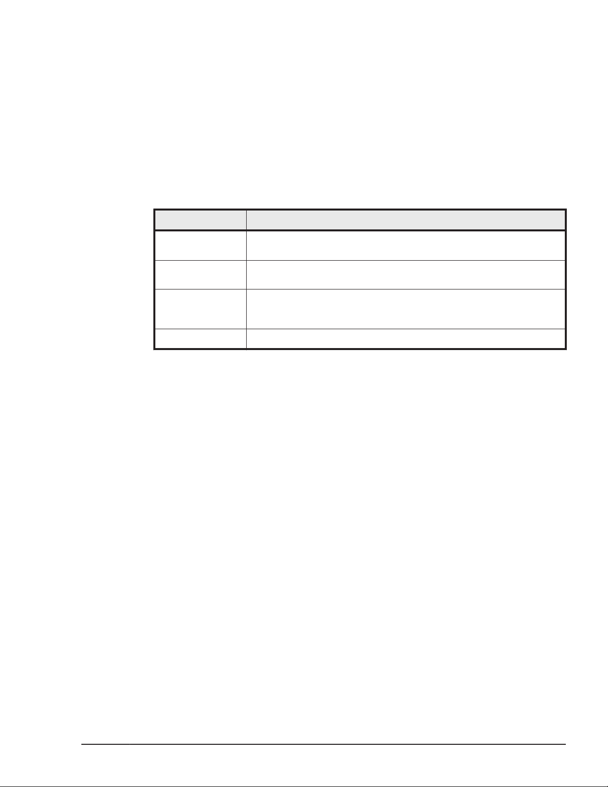
HDLM System Requirements
Check the following before installing HDLM:
For the requirements for using HDLM in an HAM environment, see the release
notes of HDLM.
Hosts and OSs Supported by HDLM
HDLM can be installed on a SPARC series computer which is running an OS
listed in the following table.
Table 3-1 Applicable OSs for the host
OS Required patches
Solaris 8 108434-04 or later, 108974-10 or later, 121972-04 or later, and
Recommended Patch Cluster Aug/27/02 or later
Solaris 9
Solaris 10
Solaris 11
#1
#2,#3,#4
118335-08 or later, and Recommended Patch Cluster Nov/12/02 or
later
119685-07 or later and 127127-11 or later are required. Also, other
patches are required depending on the host bus adapters being
used. For details on the other patches, see the HDLM Release Notes.
SRU 6.6 or later
#5
#1
If the EFI label is used, use Solaris 9 4/03 or later.
#2
If ZFS is used, use Solaris 10 6/06 or later.
#3
If a boot disk environment on ZFS is used, use Solaris 10 9/10 or later.
#4
You cannot create a Solaris Flash archive in an environment where HDLM
is installed.
#5
SRUs take the place of maintenance updates or patch bundles that are
available for Solaris 10 releases.
JDK required for linkage with Global Link Manager
To link with Global Link Manager, make sure that a JDK package listed in the
table below is already installed on the host. The JDK does not need to be
installed if linkage with Global Link Manager is not used. When HDLM is
installed in an environment in which the JDK has not been installed, the
KAPL09241-W message is displayed. If linkage with Global Link Manager is
not used, this message requires no action. Note that the display of the
KAPL09241-W message does not affect HDLM operation.
Creating an HDLM Environment
Hitachi Dynamic Link Manager (for Solaris) User Guide
3-3
Page 70

Table 3-2 JDK required for linking with Global Link Manager
OS JDK package
Solaris 8 or Solaris 9 • JDK 1.4.2_15 or later (32 bit version)
Solaris 10 • JDK 1.4.2_15 or later (32 bit version)
Solaris 11 • JDK 6.0_17 or later (32 bit version)
Storage Systems Supported by HDLM
The following shows the storage systems that HDLM supports.
Storage Systems
Applicable storage systems for use as data disks:
• JDK 5.0_11 or later (32 bit version)
• JDK 6.0_17 or later (32 bit version)
• JDK 5.0_11 or later (32 bit version)
• JDK 6.0_17 or later (32 bit version)
• JDK 7.0 (32 bit version)
• JDK 7.0 (32 bit version)
¢
Hitachi AMS2000/AMS/WMS/SMS series
¢
Hitachi NSC55
¢
Hitachi Universal Storage Platform 100
¢
Hitachi Universal Storage Platform 600
¢
Hitachi Universal Storage Platform 1100
¢
Hitachi Universal Storage Platform V
¢
Hitachi Universal Storage Platform VM
¢
Hitachi Virtual Storage Platform
¢
HP StorageWorks P9500 Disk Array
¢
Hitachi Virtual Storage Platform G1000
¢
HP XP7 Storage
¢
HUS100 series
¢
HUS VM
¢
XP128/XP1024/XP10000/XP12000/XP20000/XP24000
¢
Lightning 9900V Series
¢
SVS
¢
Thunder 9500V Series
#
3-4
#
Supports the Fibre Channel interface only.
Creating an HDLM Environment
Hitachi Dynamic Link Manager (for Solaris) User Guide
Page 71

The applicable storage systems require a dual controller configuration. If
you use the system in a hub-connected environment, you must set
unique loop IDs for all connected hosts and storage systems.
For details on the micro-programs and settings information for storage
systems, which are required to use HDLM, see the HDLM Release Notes
and maintenance documentation for the storage system.
Applicable storage systems for use as boot disks:
¢
Hitachi AMS2000/AMS/WMS/SMS series
¢
Hitachi NSC55
¢
Hitachi Universal Storage Platform 100
¢
Hitachi Universal Storage Platform 600
¢
Hitachi Universal Storage Platform 1100
¢
Hitachi Universal Storage Platform V
¢
Hitachi Universal Storage Platform VM
¢
Hitachi Virtual Storage Platform
¢
HP StorageWorks P9500 Disk Array
¢
HUS100 Series
¢
HUS VM
¢
XP10000/XP12000/XP20000/XP24000
¢
SVS
HBAs
For details on the applicable HBAs, see the HDLM Release Notes.
When Handling Intermediate Volumes Managed by Hitachi RapidXchange
When you exchange data by using intermediate volumes managed by Hitachi
RapidXchange, the following version of File Access Library and File Conversion
Utility (FAL/FCU) is required:
• For Lightning 9900V Series
01-03-56/20 or later
• Hitachi USP series
01-04-64/21 or later
• Universal Storage Platform V/VM series
01-05-66/23 or later
• VSP G1000 series
01-07-68/00 or later
For details about Hitachi RapidXchange, see the manual File Access Library &
File Conversion Utility for Solaris HP-UX AIX Windows Tru64 UNIX NCR SVR4
DYNIX/ptx Linux.
Creating an HDLM Environment
Hitachi Dynamic Link Manager (for Solaris) User Guide
3-5
Page 72
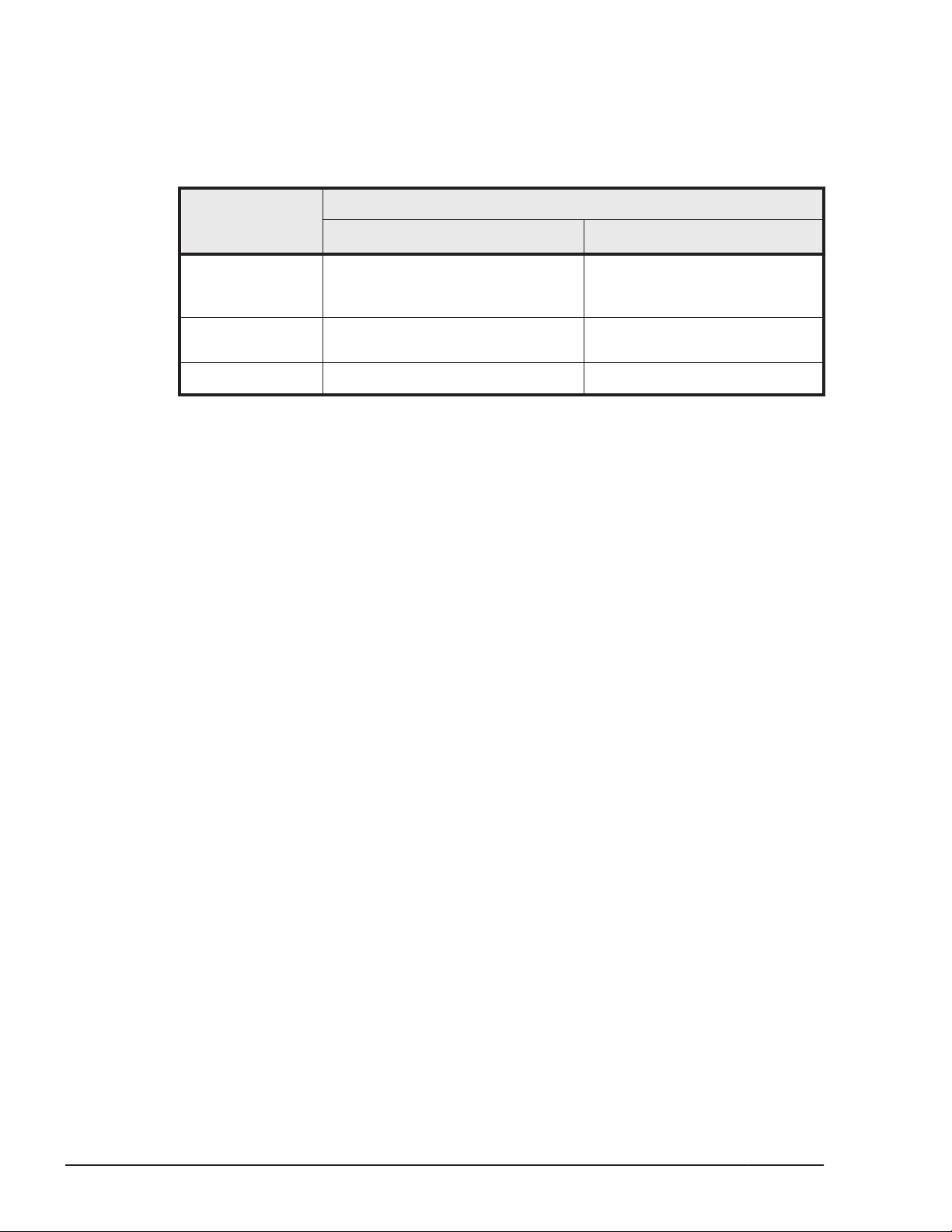
Cluster Software Supported by HDLM
The following table lists the cluster software versions supported by HDLM
when building a cluster configuration.
Table 3-3 Supported cluster software versions
Cluster software
Local boot disk environment
#5
Solaris Cluster
Oracle RAC
#3
VCS
#6
#1
An environment with a boot disk located on the host.
#2
An environment with a boot disk located in a storage system instead of in
the host.
Sun Cluster 3.1, Sun Cluster 3.2,
Oracle Solaris Cluster 3.3, or
Oracle Solaris Cluster 4.0
Oracle9i RAC, Oracle RAC 10g, or
Oracle RAC 11g
VCS5.0
#4
Supported versions
#1
Boot disk environment
Sun Cluster 3.1 8/05 (Update
4)
--
VCS5.0
#2
#4
#3
The DiskReservation agent of the VCS is not supported.
#4
You must apply MP1 or later when using the I/O fencing function. The I/O
fencing function can be used only when Hitachi USP series, Universal
Storage Platform V/VM series, or Virtual Storage Platform series storage
systems are connected in a Solaris 10 environment. Note that only the
failover and parallel service groups are supported. The hybrid service
group is not supported.
#5
Can be used when the prerequisite Sun Cluster patches are applied.
#6
The following configurations are not supported:
¢
A configuration in which Oracle RAC uses the LU that specified the EFI
label.
¢
A configuration in which Oracle RAC uses ZFS.
Volume Manager Supported by HDLM
The following shows volume managers that HDLM supports.
3-6
• When combining configurations by using SDS or SVM
SDS 4.2.1#2, or SVM 1.0
Creating an HDLM Environment
Hitachi Dynamic Link Manager (for Solaris) User Guide
Page 73

• When combining configurations by using VxVM
VxVM 4.1#1 or VxVM 5.0
#1
HDLM-managed boot disks do not support a mirrored boot disk configuration
incorporating a volume manager such as SDS or VxVM. For this reason, you
cannot register an HDLM-managed boot disk in bootdg when using VxVM.
The following configurations are supported for HDLM-managed boot disks:
For SVM
¢
OS: Solaris 10
¢
RAID level: Mirroring (no more than three mirrors)
¢
Cluster: None
For ZFS
¢
OS: Solaris 10 or Solaris 11
¢
Single-disk configuration
¢
Cluster: None
#1
When used with the Thunder 9500V series, Lightning 9900V series,
Hitachi USP series, Hitachi AMS2000/AMS/WMS/SMS series, Universal
Storage Platform V/VM series, or Virtual Storage Platform series storage
systems, the Array Support Library of VxVM is required. If the Array
Support Library of VxVM is not installed, install it before installing HDLM.
For details on how to install the Array Support Library, see the storage
system documentation.
#2
Can be used when Patch 108693-07 or later is applied for Solaris 8.
Combinations of Cluster Software and Volume Managers Supported by HDLM
For the Solaris Cluster or VCS Environment
The following table lists the combinations of cluster software and volume
managers that are supported by HDLM.
Table 3-4 Combinations of related programs supported by HDLM
OS Cluster Volume manager
Solaris 8 None None
SDS 4.2.1
VxVM 5.0
Sun Cluster 3.1
#1
None
SDS 4.2.1
Creating an HDLM Environment
Hitachi Dynamic Link Manager (for Solaris) User Guide
3-7
Page 74

OS Cluster Volume manager
Sun Cluster 3.1 (9/04)
#1
None
SDS 4.2.1
Sun Cluster 3.1 (8/05)
#1
None
SDS 4.2.1
VCS 5.0
#2 #3
None
VxVM 5.0
Solaris 9 None None
SVM
VxVM 5.0
Sun Cluster 3.1
#1 #5
None
SVM
Sun Cluster 3.1 (9/04)
#1 #5
None
SVM
Sun Cluster 3.1 (8/05)
#1 #5
None
SVM
VCS 5.0
#2 #3 #5
None
VxVM 5.0
#4
#5
#6
#6
#6
Solaris 10 None None
SVM 1.0
VxVM 5.0
Sun Cluster 3.1 (8/05)
#1 #5 #8
None
SVM
Sun Cluster 3.2
#1 #10
None
SVM
VxVM 5.0
Sun Cluster 3.2 (2/08)
#1 #10 #13
None
SVM
VxVM 5.0
Sun Cluster 3.2 (1/09)
#10 #13
None
SVM
VxVM 5.0
Sun Cluster 3.2 (11/09)
#10 #13
None
#4 #7 #8
#5 #8
#6 #9
#11
#5 #6 #8 #9
#5 #8 #12
#11
#5 #6 #8 #9
#5 #8 #12
#6 #9
3-8
Creating an HDLM Environment
Hitachi Dynamic Link Manager (for Solaris) User Guide
Page 75

OS Cluster Volume manager
#4 #9
SVM
VxVM 5.0
Oracle Solaris Cluster 3.3
VCS 5.0
VCS 5.1
VCS 6.0
#3
#14
#16
#10 #13
None
#5 #6 #8 #9
SVM
VxVM 5.1
#14
None
VxVM 5.0
None
VxVM 5.1
VxVM 6.0
#5 #8
#5 #8 #15
#5 #8
#5 #8
Solaris 11 Oracle Solaris Cluster 4.0 None
SVM
VCS 6.0
VxVM 6.0
#5 #8
#1
In either of the following cases, the load balancing function is disabled
because a reservation is issued to one of the LUs that is in use:
¢
When a failure occurs on one of the nodes in a two-node configuration
running Sun Cluster and the LU cannot be accessed
¢
When the SDS 4.2.1 or SVM 1.0 shared diskset is being used in an
environment without Sun Cluster
#2
Does not support the I/O fencing function.
#3
Does not support linkage with SFVS (Storage Foundation Volume Server).
#4
Does not support the following SVM functions:
¢
Multi-owner disksets
¢
Diskset import
¢
Automatic (top down) volume creation
#5
Does not support the EFI label.
#6
Does not support the following SVM functions:
¢
Handling disks whose capacity is 1 TB or more
Creating an HDLM Environment
Hitachi Dynamic Link Manager (for Solaris) User Guide
3-9
Page 76

¢
Multi-owner disksets
¢
Diskset import
¢
Automatic (top down) volume creation
#7
In a configuration that uses a driver other than the Oracle HBA driver
(other than the qlc or emlxs driver), the SVM shared diskset cannot use
disks managed by HDLM.
#8
Does not support ZFS.
#9
When the SVM shared diskset uses disks managed by HDLM in a
configuration that uses a driver other than the Oracle HBA driver (other
than the qlc or emlxs driver), use Sun Cluster device IDs (logical device
files under /dev/did/dsk). The SVM shared diskset cannot use HDLM
logical device names.
#10
For a two-node configuration, the pathcount setting is only supported for
the SCSI protocol (fencing protocol) of the storage device.
For details on how to specify SCSI protocols for storage devices, refer to
the Sun Cluster manual.
#11
For the EFI label or ZFS, only two-node configurations are supported.
#12
You must apply MP1 or later.
#13
Only two-node configurations are supported.
#14
You must apply MP1 or later when using the I/O fencing function. The I/O
fencing function can be used only when Hitachi USP series, Universal
Storage Platform V/VM series, or Virtual Storage Platform series storage
systems are connected in a Solaris 10 environment. Note that the only
supported service group type is the failover service group. The parallel
service group and hybrid service group are not supported.
#15
You must apply MP1 or later when using the I/O fencing function. The I/O
fencing function can be used only when Hitachi USP series, Universal
Storage Platform V/VM series, or Virtual Storage Platform series storage
systems are connected in a Solaris 10 environment. Note, the parallel
service group is the only supported service group type. The failover
service group and hybrid service group are not supported.
3-10
#16
Creating an HDLM Environment
Hitachi Dynamic Link Manager (for Solaris) User Guide
Page 77

The I/O fencing function can be used only when Hitachi USP series,
Universal Storage Platform V/VM series, or Virtual Storage Platform series
storage systems are connected in a Solaris 10 environment. Note that the
only supported service group type is the failover service group. The
parallel service group and hybrid service group are not supported.
When Creating an Oracle9i RAC Environment
Required programs
The following table lists the programs required to create an Oracle9i RAC
environment.
Table 3-5 Programs required to create an Oracle9i RAC environment (for
Solaris 10)
Program Remarks
OS Solaris 10 --
Cluster Sun Cluster 3.1 8/05 HDLM supports the two-node
configuration only.
Sun Cluster Support for Oracle
Parallel Server/Real Application
Clusters 3.1
Oracle9i 9.2.0.8.0 RAC is bundled with
Oracle UNIX Distributed Lock
Manager 3.3.4.8
Volume Manager None (Specify an HDLM raw
device by the device ID of Sun
Cluster)
When Creating an Oracle RAC 10g Environment
Required programs
Table 3-6 Programs required to create an Oracle RAC 10g environment (For
Solaris 8 or Solaris 9) on page 3-12 and Table 3-7 Programs required to
create an Oracle RAC 10g environment (For Solaris 10) on page 3-14 show
programs required to create an Oracle RAC 10g environment.
Required packages:
• SUNWschwr
• SUNWscor
• SUNWscucm
• SUNWudlm
• SUNWudlmr
Oracle9i.
Required packages:
ORCLudlm
--
Creating an HDLM Environment
Hitachi Dynamic Link Manager (for Solaris) User Guide
3-11
Page 78
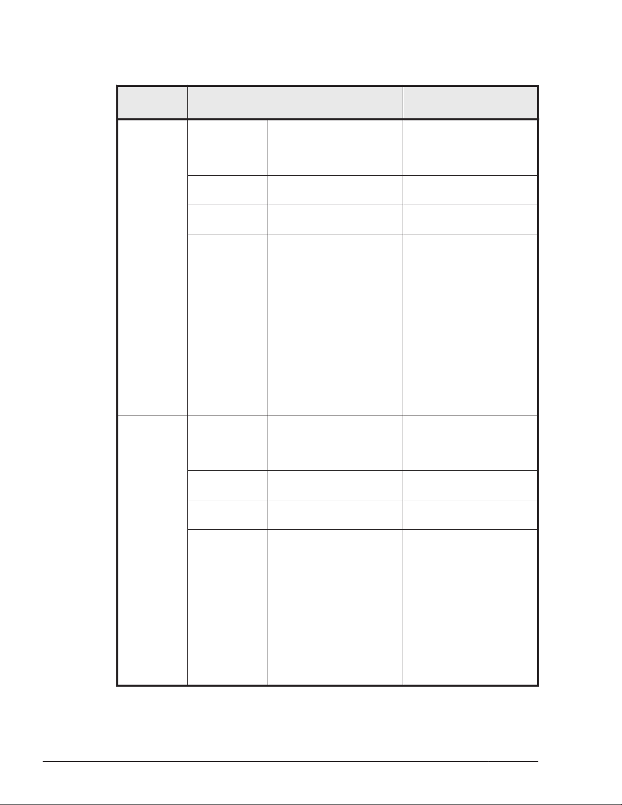
Table 3-6 Programs required to create an Oracle RAC 10g environment
(For Solaris 8 or Solaris 9)
Configurati
on
Configuration1OS Solaris 8 or Solaris 9 • In Solaris 8, use
Oracle RAC 10g Oracle 10g Database
Cluster Oracle Cluster Ready
Volume
Manager
Program Remarks
Update 7 or later.
• In Solaris 9, use
Update 6 or later.
--
10.1.0.2.0
--
Services (CRS) 10.1.0.2.0
ASM • ASM is bundled with
Oracle RAC 10g.
• ASM is used as the
disk memory area for
files and recovery files
of the Oracle database.
In Oracle RAC 10g,
HDLM devices can be
used following the
same procedures as
for disk devices.
For details on how to
install ASM, refer to
the documentation for
Oracle RAC 10g.
Configuration2OS Solaris 8 or Solaris 9 • In Solaris 8, use
Update 7 or later.
• In Solaris 9, use
Update 6 or later.
Oracle RAC 10g Oracle 10g Database
10.2.0.1.0
Cluster Oracle Clusterware
10.2.0.1.0
Volume
Manager
ASM • ASM is bundled with
--
--
Oracle RAC 10g.
• ASM is used as the
disk memory area for
files and recovery files
of the Oracle database.
In Oracle RAC 10g,
HDLM devices can be
used following the
same procedures as
for disk devices.
For details on how to
install ASM, refer to
3-12
Creating an HDLM Environment
Hitachi Dynamic Link Manager (for Solaris) User Guide
Page 79

Configurati
on
Configuration3OS Solaris 9 --
Program Remarks
the documentation for
Oracle RAC 10g.
Oracle RAC 10g Oracle 10g Database
10.1.0.4.0
Cluster Oracle Clusterware
10.1.0.4.0
Volume
Manager
Configuration4OS Solaris 9 --
Oracle RAC 10g Oracle 10g Database
Cluster Oracle Clusterware
Volume
Manager
Configuration5OS Solaris 9 --
Oracle RAC 10g Oracle 10g Database
Cluster Oracle Clusterware
Volume
Manager
None (Specify an HDLM
raw device)
10.1.0.5.0
10.1.0.5.0
None (Specify an HDLM
raw device)
10.2.0.2.0
10.2.0.2.0
None (Specify an HDLM
raw device)
--
--
--
--
--
--
--
--
--
Configuration6OS Solaris 9 --
Oracle RAC 10g Oracle 10g Database
10.2.0.2.0
Cluster Sun Cluster 3.1 8/05 and
Oracle Clusterware
10.2.0.2.0
Volume
Manager
Configuration7OS Solaris 9 --
Oracle RAC 10g Oracle 10g Database
Cluster Oracle Clusterware
Volume
Manager
None (Specify an HDLM
raw device by the device ID
of Sun Cluster)
10.2.0.3.0
10.2.0.3.0
ASM • ASM is bundled with
Only configurations that
consist of three or more
nodes are supported.
--
--
--
• ASM is used as the
Oracle RAC 10g.
disk memory area for
files and recovery files
Creating an HDLM Environment
Hitachi Dynamic Link Manager (for Solaris) User Guide
3-13
Page 80

Configurati
on
Program Remarks
of the Oracle database.
In Oracle RAC 10g,
HDLM devices can be
used following the
same procedures as
for disk devices.
For details on how to
install ASM, refer to
the documentation for
Oracle RAC 10g.
Table 3-7 Programs required to create an Oracle RAC 10g environment
(For Solaris 10)
Configurati
on
Configuratio
n 1
Configuratio
n 2
Program Remarks
OS Solaris 10 --
Oracle RAC
10g
Cluster Oracle Cluster Ready
Volume
Manager
OS Solaris 10 --
Oracle RAC
10g
Oracle 10g Database
10.1.0.4.0
Services (CRS) 10.1.0.4.0
ASM • ASM is bundled with
Oracle 10g Database
10.1.0.5.0
--
--
Oracle RAC 10g.
• ASM is used as the disk
memory area for files
and recovery files of
the Oracle database. In
Oracle RAC 10g, HDLM
devices can be used
following the same
procedures as for disk
devices.
For details on how to
install ASM, refer to the
documentation for
Oracle RAC 10g.
--
3-14
Configuratio
n 3
Hitachi Dynamic Link Manager (for Solaris) User Guide
Cluster Oracle Clusterware
10.1.0.5.0
Volume
Manager
OS Solaris 10 --
Oracle RAC
10g
None (Specify an HDLM raw
device)
Oracle 10g Database
10.2.0.1.0
Creating an HDLM Environment
--
--
--
Page 81

Configurati
on
Program Remarks
Configuratio
n 4
Cluster Oracle Clusterware
10.2.0.1.0
Volume
Manager
OS Solaris 10 --
Oracle RAC
10g
Cluster Oracle Clusterware
Volume
Manager
ASM • ASM is bundled with
Oracle 10g Database
10.2.0.2.0
10.2.0.2.0
ASM • ASM is bundled with
--
Oracle RAC 10g.
• ASM is used as the disk
memory area for files
and recovery files of
the Oracle database. In
Oracle RAC 10g, HDLM
devices can be used
following the same
procedures as for disk
devices.
For details on how to
install ASM, refer to the
documentation for
Oracle RAC 10g.
--
--
Oracle RAC 10g.
• ASM is used as the disk
memory area for files
and recovery files of
the Oracle database. In
Oracle RAC 10g, HDLM
devices can be used
following the same
procedures as for disk
devices.
For details on how to
install ASM, refer to the
documentation for
Oracle RAC 10g.
Configuratio
n 5
Configuratio
n 6
Hitachi Dynamic Link Manager (for Solaris) User Guide
OS Solaris 10 --
Oracle RAC
10g
Cluster Oracle Clusterware
Volume
Manager
OS Solaris 10 --
Oracle 10g Database
10.2.0.2.0
10.2.0.2.0
None (Specify an HDLM raw
device)
Creating an HDLM Environment
--
--
--
3-15
Page 82

Configurati
on
Program Remarks
Configuratio
n 7
Oracle RAC
10g
Cluster Sun Cluster 3.1 8/05 and
Volume
Manager
OS Solaris 10 --
Oracle RAC
10g
Cluster Sun Cluster 3.1 8/05 and
Volume
Manager
Oracle 10g Database
10.2.0.2.0
Oracle Clusterware
10.2.0.2.0
None (Specify an HDLM raw
device by the device ID of
Sun Cluster)
Oracle 10g Database
10.2.0.2.0
Oracle Clusterware
10.2.0.2.0
VxVM 4.1 cluster
functionality
Only two-node
configurations are
supported.
--
Only two-node
configurations are
supported.
Allocates memory areas,
shared among nodes, such
as Oracle database files,
SPFILE, REDO log files,
Oracle Cluster Registry, and
voting disks, to the VxVM
4.1 cluster functionality
volumes. For details on how
to allocate memory areas,
refer to the documentation
for Oracle RAC 10g.
Configuratio
n 8
Configuratio
n 9
OS Solaris 10 --
Oracle RAC
10g
Cluster Oracle Clusterware
Volume
Manager
OS Solaris 10 --
Oracle RAC
10g
Cluster Oracle Clusterware
Volume
Manager
Oracle 10g Database
10.2.0.3.0
10.2.0.3.0
None (Specify an HDLM raw
device)
Oracle 10g Database
10.2.0.3.0
10.2.0.3.0
ASM • ASM is bundled with
--
--
--
--
--
Oracle RAC 10g.
• ASM is used as the disk
memory area for files
and recovery files of
the Oracle database. In
Oracle RAC 10g, HDLM
devices can be used
following the same
3-16
Creating an HDLM Environment
Hitachi Dynamic Link Manager (for Solaris) User Guide
Page 83
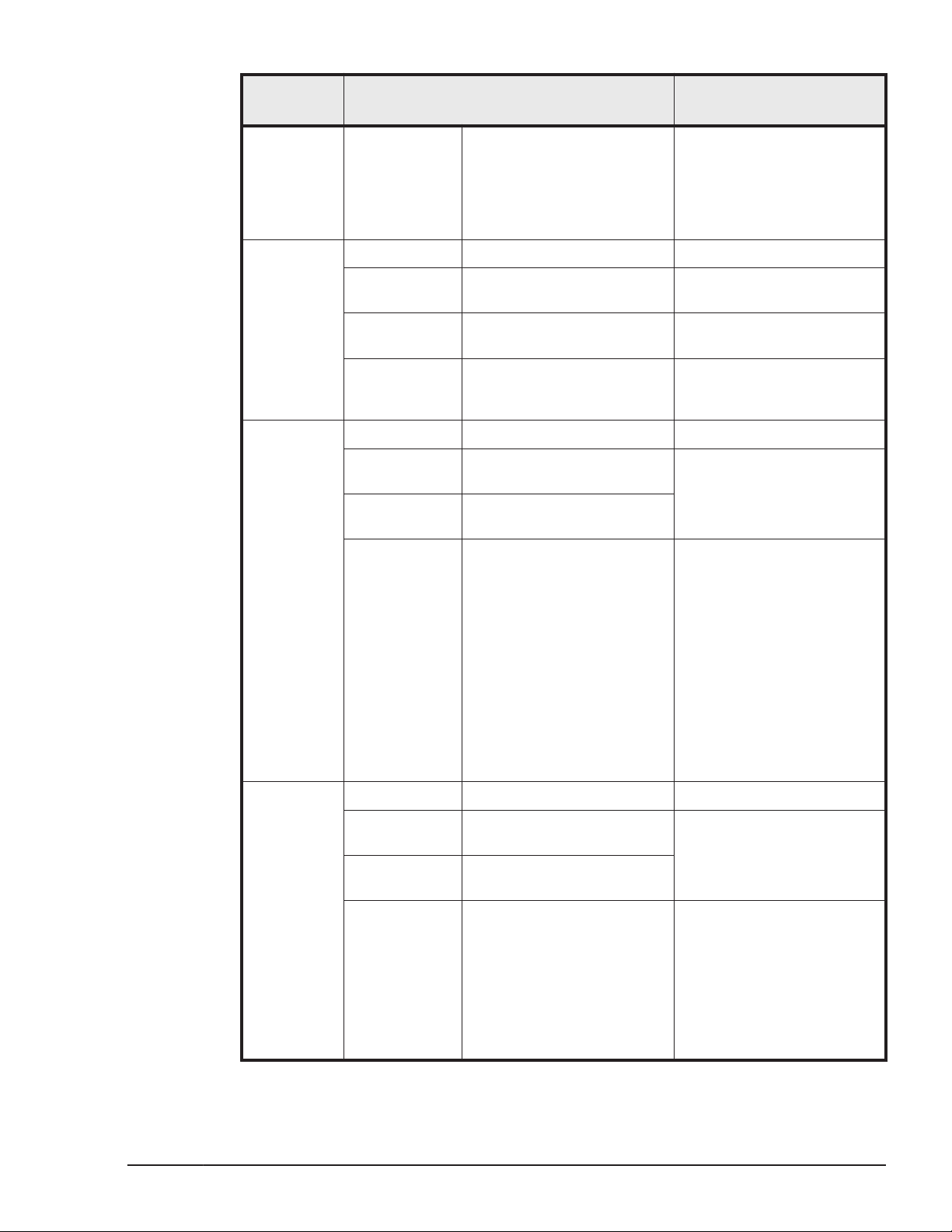
Configurati
on
Program Remarks
procedures as for disk
devices.
For details on how to
install ASM, refer to the
documentation for
Oracle RAC 10g.
Configuratio
n 10
Configuratio
n 11
OS Solaris 10 --
Oracle RAC
10g
Cluster Sun Cluster 3.2 and Oracle
Volume
Manager
OS Solaris 10 --
Oracle RAC
10g
Cluster Sun Cluster 3.2 and Oracle
Volume
Manager
Oracle 10g Database
10.2.0.3.0
Clusterware 10.2.0.3.0
None (Specify an HDLM raw
device from the Sun Cluster
device ID)
Oracle 10g Database
10.2.0.3.0
Clusterware 10.2.0.3.0
ASM • ASM is bundled with
--
--
--
Only configurations that
consist of three or more
nodes are supported.
Oracle RAC 10g.
• ASM is used as the disk
memory area for the
Oracle database files
and recovery files. For
the disk device used by
ASM, specify the Sun
Cluster device ID.
For details on how to
use ASM, refer to the
documentation for
Oracle RAC 10g.
Configuratio
n 12
Hitachi Dynamic Link Manager (for Solaris) User Guide
OS Solaris 10 --
Oracle RAC
10g
Cluster Sun Cluster 3.2 and Oracle
Volume
Manager
Oracle 10g Database
10.2.0.3.0
Clusterware 10.2.0.3.0
VxVM 5.0 cluster
functionality
#
Creating an HDLM Environment
Only two-node
configurations are
supported.
Allocates memory areas,
shared among nodes, such
as Oracle database files,
SPFILE, REDO log files,
Oracle Cluster Registry, and
voting disks, to the VxVM
5.0 cluster functionality
volumes. For details on how
to allocate memory areas,
3-17
Page 84

Configurati
on
Program Remarks
refer to the documentation
for Oracle RAC 10g.
Configuratio
n 13
Configuratio
n 14
OS Solaris 10 --
Oracle RAC
10g
Cluster Sun Cluster 3.2 and Oracle
Volume
Manager
OS Solaris 10 --
Oracle RAC
10g
Cluster Sun Cluster 3.2 and Oracle
Volume
Manager
Oracle 10g Database
10.2.0.4.0
Clusterware 10.2.0.4.0
VxVM 5.0 cluster
functionality
Oracle 10g Database
10.2.0.4.0
Clusterware 10.2.0.4.0
None (Specify an HDLM raw
device from the Sun Cluster
device ID)
#
Only two-node
configurations are
supported.
Allocates memory areas,
shared among nodes, such
as Oracle database files,
SPFILE, REDO log files,
Oracle Cluster Registry, and
voting disks, to the VxVM
5.0 cluster functionality
volumes. For details on how
to allocate memory areas,
refer to the documentation
for Oracle RAC 10g.
Only two-node
configurations are
supported.
--
Configuratio
n 15
Configuratio
n 16
OS Solaris 10 --
Oracle RAC
10g
Cluster Oracle Solaris Cluster 3.3
Volume
Manager
OS Solaris 10 --
Oracle RAC
10g
Cluster Oracle Solaris Cluster 3.3
Volume
Manager
Oracle 10g Database
10.2.0.3.0
and Oracle Clusterware
10.2.0.3.0
None (Specify an HDLM raw
device from the Sun Cluster
device ID)
Oracle 10g Database
10.2.0.3.0
and Oracle Clusterware
10.2.0.3.0
ASM • ASM is bundled with
--
--
--
Only configurations that
consist of three or more
nodes are supported.
Oracle RAC 10g.
• ASM is used as the disk
memory area for the
3-18
Creating an HDLM Environment
Hitachi Dynamic Link Manager (for Solaris) User Guide
Page 85

Configurati
on
Program Remarks
Oracle database files
and recovery files. For
the disk device used by
ASM, specify the Sun
Cluster device ID.
For details on how to
use ASM, refer to the
documentation for
Oracle RAC 10g.
Configuratio
n 17
Configuratio
n 18
OS Solaris 10 --
Oracle RAC
10g
Cluster Oracle Solaris Cluster 3.3
Volume
Manager
OS Solaris 10 --
Oracle RAC
10g
Cluster Oracle Solaris Cluster 3.3
Oracle 10g Database
10.2.0.3.0
and Oracle Clusterware
10.2.0.3.0
VxVM 5.1 cluster
functionality
Oracle 10g Database
10.2.0.4.0
and Oracle Clusterware
10.2.0.4.0
#
Only two-node
configurations are
supported.
Allocates memory areas,
shared among nodes, such
as Oracle database files,
SPFILE, REDO log files,
Oracle Cluster Registry, and
voting disks, to the VxVM
5.1 cluster functionality
volumes. For details on how
to allocate memory areas,
refer to the documentation
for Oracle RAC 10g.
Only two-node
configurations are
supported.
Configuratio
n 19
Hitachi Dynamic Link Manager (for Solaris) User Guide
Volume
Manager
OS Solaris 10 --
Oracle RAC
10g
VxVM 5.1 cluster
functionality
Oracle 10g Database
10.2.0.4.0
#
Creating an HDLM Environment
Allocates memory areas,
shared among nodes, such
as Oracle database files,
SPFILE, REDO log files,
Oracle Cluster Registry, and
voting disks, to the VxVM
5.1 cluster functionality
volumes. For details on how
to allocate memory areas,
refer to the documentation
for Oracle RAC 10g.
Only two-node
configurations are
supported.
3-19
Page 86
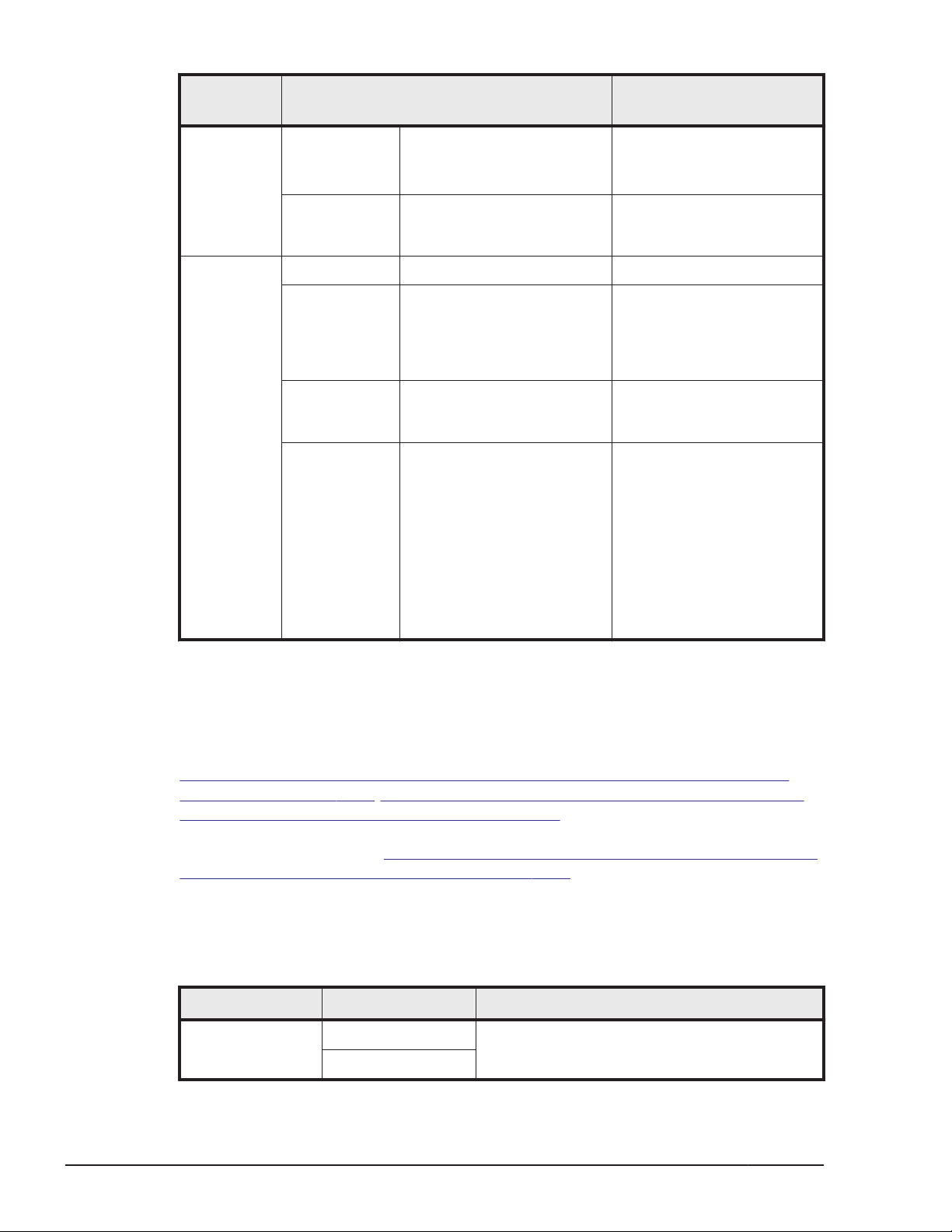
Configurati
on
Program Remarks
Cluster Oracle Solaris Cluster 3.3
and Oracle Clusterware
10.2.0.4.0
Configuratio
n 20
Volume
Manager
OS Solaris 10 --
Oracle RAC
10g
Cluster
Volume
Manager
None (Specify an HDLM raw
device from the Sun Cluster
device ID)
Oracle 10g Database
10.2.0.4.0
VCS 5.0
VxVM 5.0 cluster
functionality
#
#
--
Configurations that use
Storage Foundation for
Oracle RAC 5.0 (where the
MP version is the same as
that of VCS) are supported.
The parallel service group
with an I/O fencing function
enabled is supported.
Allocates memory areas,
shared among nodes, such
as Oracle database files,
SPFILE, REDO log files,
Oracle Cluster Registry, and
voting disks, to the VxVM
5.0 cluster functionality
volumes. For details on how
to allocate memory areas,
refer to the documentation
for Oracle RAC 10g.
#
You must apply MP1 or later.
Required patches
Table 3-8 Patches required to create an Oracle RAC 10g environment (For
Solaris 8) on page 3-20,Table 3-9 Patches required to create an Oracle RAC
10g environment (For Solaris 9) on page 3-21 show patches that are
provided by Oracle Inc. and are required to create an Oracle RAC 10g
environment. Table 3-11
10g environment (For Solaris 10) on page 3-21 show patches that are
provided by Oracle Corporation and are required to create an Oracle RAC 10g
environment.
Table 3-8 Patches required to create an Oracle RAC 10g environment (For
Target program Patch ID Timing for applying
Oracle RAC 10g 108528-23 or later Apply the patch before installing Oracle RAC
108652-66 or later
Table 3-10 Patches required to create an Oracle RAC
Solaris 8)
10g.
3-20
Creating an HDLM Environment
Hitachi Dynamic Link Manager (for Solaris) User Guide
Page 87

Target program Patch ID Timing for applying
108773-18 or later
108921-16 or later
108940-53 or later
108987-13 or later
108989-02 or later
108993-19 or later
109147-24 or later
110386-03 or later
111023-02 or later
111111-03 or later
111308-03 or later
111310-01 or later
112396-02 or later
111721-04 or later
112003-03 or later
#
112138-01 or later
#
When using Oracle RAC 10g 10.2.0.1.0, apply 108993-45, not
108993-19.
Table 3-9 Patches required to create an Oracle RAC 10g environment (For
Solaris 9)
Target program Patch ID Timing for applying
Oracle RAC 10g 112233-11 or later Apply the patch before installing Oracle RAC
111722-04 or later
113801-12 or later
10g.
#
#
It is necessary only for a configuration where Sun Cluster 3.1 8/05 is
used as the cluster.
Table 3-10 Patches required to create an Oracle RAC 10g environment (For
Solaris 10)
Target program Patch ID Timing for applying
Oracle RAC 10g
P4332242
#
Apply the patch after installing Oracle RAC
10g.
Creating an HDLM Environment
Hitachi Dynamic Link Manager (for Solaris) User Guide
3-21
Page 88

#
It is necessary only when using Oracle RAC 10g 10.1.0.4.0.
Note
• When a host and an Oracle RAC 10g voting disk are connected by
multiple paths, HDLM performs failover processing for those paths (in the
same way as for normal paths) when an I/O timeout occurs for one of the
paths.
Note that, depending on the settings of Oracle RAC 10g, Oracle RAC 10g
might determine that a node error has occurred before the failover
processing performed by HDLM is completed, and then re-configure the
cluster.
Therefore, when HDLM manages the paths that are connected to an
Oracle RAC 10g voting disk, change the following settings according to
your version of Oracle RAC 10g:
¢
When using Oracle RAC 10g version 10.1.0.3.0 or later:
Change the value of MISSCOUNT according to the storage system type.
Specify a value that is equal to or greater than the value calculated by
using the formulas in the following table:
Table 3-11 Formula for Calculating MISSCOUNT
Storage system type
• Lightning 9900V series
• Hitachi USP series
• Universal Storage
Platform V/VM series
• Virtual Storage Platform
series
• VSP G1000 series
• HUS VM
• Hitachi
AMS2000/AMS/WMS/SMS
series
• HUS100 series
• Thunder 9500V series
¢
When using Oracle RAC 10g version 10.2.0.2.0 or later:
Formula for obtaining the value of
MISSCOUNT
number-of-paths-connected-to-the-voting-disk
x 60 seconds
number-of-paths-connected-to-the-voting-disk
x 30 seconds
Change the value of MISSCOUNT according to the storage system type.
Specify a value that is equal to or greater than the value calculated by
using the formulas in the table below.
When you are using Sun Cluster or Storage Foundation for Oracle
RAC, specify a value equal to or greater than either of the values
indicated below:
3-22
• Calculated value of MISSCOUNT
Creating an HDLM Environment
Hitachi Dynamic Link Manager (for Solaris) User Guide
Page 89

• 600 seconds (default value of Oracle Clusterware)
Table 3-12 Formula for Calculating MISSCOUNT
Storage system type
• Lightning 9900V series
• Hitachi USP series
• Universal Storage
Platform V/VM series
• Virtual Storage Platform
series
• VSP G1000 series
• HUS VM
• Hitachi
AMS2000/AMS/WMS/SMS
series
• HUS100 series
• Thunder 9500V series
Formula for obtaining the value of
MISSCOUNT
number-of-paths-connected-to-the-voting-disk
x 60 seconds
number-of-paths-connected-to-the-voting-disk
x 30 seconds
In addition to the value of MISSCOUNT shown above, also change the
value of DISKTIMEOUT. As with MISSCOUNT, the value to be specified in
DISKTIMEOUT is determined by the type of storage system. To make
the change, use the following table to obtain the value to be specified,
and then change the current value to a value equal to or greater than
the value you have obtained.
Table 3-13 Formula for Calculating DISKTIMEOUT
Storage system type
• Lightning 9900V series
• Hitachi USP series
• Universal Storage
Platform V/VM series
• Virtual Storage Platform
series
• VSP G1000 series
• HUS VM
• Hitachi
AMS2000/AMS/WMS/SM
S series
• HUS100 series
• Thunder 9500V series
Number
of paths
connecte
d to the
Formula for obtaining the value of
DISKTIMEOUT
voting
disk
3 or less You do not need to change the value
of DISKTIMEOUT.
4 or more number-of-paths-connected-to-the-
voting-disk x 60 seconds
6 or less You do not need to change the value
of DISKTIMEOUT.
7 or more number-of-paths-connected-to-the-
voting-disk x 30 seconds
Creating an HDLM Environment
Hitachi Dynamic Link Manager (for Solaris) User Guide
3-23
Page 90

For details on how to change MISSCOUNT and DISKTIMEOUT, contact the
company with which you have a contract for Oracle Support Services.
Note that when you remove HDLM from the above configuration, you
must reset the values of MISSCOUNT and DISKTIMEOUT to their original
values. Therefore, make a note of the original values of MISSCOUNT and
DISKTIMEOUT before changing them.
• In Oracle RAC 10g, for the following devices, device name should be
matching between the nodes:
¢
voting disk
¢
Oracle Cluster Registry
¢
Oracle database file
¢
system table area
¢
users table area
¢
ASM disk to be used for ASM disk group creation
In an environment where an HDLM raw device is used as the devices
listed above, if the HDLM raw device name does not match between the
nodes, create an alias device file of the HDLM raw device in each node by
using the following procedure and set the created alias device file in
Oracle RAC 10g.
a. Check the major number and minor number of HDLM raw devices
used by Oracle RAC 10g by executing the following command in each
node:
# ls -lL HDLM-raw-device-file
Execution example:
# ls -lL /dev/rdsk/c10t50060E8005271760d5s0
crw-r----- 1 root sys 307, 1608 date/time /dev/rdsk/
c10t50060E8005271760d5s0
#
In this example, the major number is 307 and the minor number is
1608.
3-24
b. Create an alias device file by executing the following command in
each node. An alias device file corresponding to one disk slice should
have the same name in all the nodes.
# mknod /dev/alias-device-file c major-number minor-number
Note:
The name of the alias device file should not be duplicated with a
device file name created under the /dev directory by Solaris or other
drivers.
Execution example:
# mknod /dev/crs_ocr1 c 307 1608
#
In this example, a device file for RAC whose major number is 307 and
minor number is 1608 is created.
Creating an HDLM Environment
Hitachi Dynamic Link Manager (for Solaris) User Guide
Page 91

c. For the created alias device file, set the owner, group, and access
permission mode by using the following command. The owner, group,
and access permission mode to be set differs depending on the usage
purpose of Oracle RAC 10g corresponding to that device. For details
on this point, refer to the Oracle documentation.
# chmod mode /dev/alias-device-file
# chown owner:group /dev/alias-device-file
Execution example:
# chmod 640 /dev/crs_ocr1
# chown root:oinstall /dev/crs_ocr1
#
d. Execute the following command for the created alias device file and
check that the major number, minor number, owner, group, and
access permission mode is properly set:
# ls -l /dev/alias-device-file
Execution example:
# ls -l /dev/crs_ocr1
crw-r----- 1 root oinstall 307, 1608 date/time /dev/crs_ocr1
#
When Creating an Oracle RAC 11g Environment
Required programs
The following table lists programs required to create an Oracle RAC 11g
environment.
Table 3-14 Programs required to create an Oracle RAC 11g environment
(For Solaris 10 or Solaris 11)
Configurati
on
Configuratio
n 1
Configuratio
n 2
OS Solaris 10 --
Oracle RAC 11g Oracle 11g Database
Cluster Oracle Clusterware
Volume
Manager
OS Solaris 10 --
Oracle RAC 11g Oracle 11g Database
Cluster Oracle Clusterware
Program Remarks
--
11.1.0.6.0
--
11.1.0.6.0
None (Specify an HDLM
raw device)
11.1.0.6.0
11.1.0.6.0
--
--
--
Creating an HDLM Environment
Hitachi Dynamic Link Manager (for Solaris) User Guide
3-25
Page 92

Configurati
on
Program Remarks
Configuratio
n 3
Configuratio
n 4
Volume
Manager
OS Solaris 10 --
Oracle RAC 11g Oracle 11g Database
Cluster Sun Cluster 3.1 8/05 and
Volume
Manager
OS Solaris 10 --
Oracle RAC 11g Oracle 11g Database
ASM • ASM is bundled with
• ASM is used as the disk
Only two-node configurations
11.1.0.6.0
Oracle Clusterware
11.1.0.6.0
None (Specify an HDLM
raw device)
11.1.0.6.0
are supported.
--
Only two-node configurations
are supported.
Oracle RAC 11g.
memory area for the
Oracle database files and
recovery files. In Oracle
RAC 11g, HDLM devices
can be used following
the same procedures as
for disk devices.
For details on how to use
ASM, refer to the
documentation for
Oracle RAC 11g.
Configuratio
n 5
Cluster Sun Cluster 3.1 8/05 and
Oracle Clusterware
11.1.0.6.0
Volume
Manager
OS Solaris 10 --
Oracle RAC 11g Oracle 11g Database
Cluster Sun Cluster 3.2 and Oracle
ASM • ASM is bundled with
• ASM is used as the disk
Only two-node configurations
11.1.0.6.0
Clusterware 11.1.0.6.0
are supported.
Oracle RAC 11g.
memory area for the
Oracle database files and
recovery files. For the
disk device used by
ASM, specify the Sun
Cluster device ID.
For details on how to use
ASM, refer to the
documentation for
Oracle RAC 11g.
3-26
Creating an HDLM Environment
Hitachi Dynamic Link Manager (for Solaris) User Guide
Page 93

Configurati
on
Program Remarks
Configuratio
n 6
Configuratio
n 7
Volume
Manager
OS Solaris 10 --
Oracle RAC 11g Oracle 11g Database
Cluster Sun Cluster 3.2 and Oracle
Volume
Manager
OS Solaris 10 --
Oracle RAC 11g Oracle 11g Database
None (Specify an HDLM
raw device)
11.1.0.6.0
Clusterware 11.1.0.6.0
ASM • ASM is bundled with
11.1.0.6.0
--
Only two-node configurations
are supported.
• ASM is used as the disk
Only two-node configurations
are supported.
Oracle RAC 11g.
memory area for the
Oracle database files and
recovery files. For the
disk device used by
ASM, specify the Sun
Cluster device ID.
For details on how to use
ASM, refer to the
documentation for
Oracle RAC 11g.
Configuratio
n 8
Cluster Oracle Solaris Cluster 3.3
and Oracle Clusterware
11.1.0.6.0
Volume
Manager
OS Solaris 10 --
Oracle RAC 11g Oracle 11g Database
Cluster Oracle Solaris Cluster 3.3
Volume
Manager
None (Specify an HDLM
raw device)
11.1.0.6.0
and Oracle Clusterware
11.1.0.6.0
ASM • ASM is bundled with
--
Only two-node configurations
are supported.
• ASM is used as the disk
Oracle RAC 11g.
memory area for the
Oracle database files and
recovery files. For the
disk device used by
ASM, specify the Sun
Cluster device ID.
For details on how to use
ASM, refer to the
Creating an HDLM Environment
Hitachi Dynamic Link Manager (for Solaris) User Guide
3-27
Page 94

Configurati
on
Program Remarks
documentation for
Oracle RAC 11g.
Configuratio
n 9
Configuratio
n 10
OS Solaris 10 --
Oracle RAC 11g Oracle 11g Database
11.1.0.7.0
Cluster Oracle Clusterware
11.1.0.7.0
Volume
Manager
OS Solaris 10 --
Oracle RAC 11g Oracle 11g Database
Cluster Oracle Clusterware
Volume
Manager
None (Specify an HDLM
raw device)
11.1.0.7.0
11.1.0.7.0
ASM • ASM is bundled with
--
--
--
--
--
• ASM is used as the disk
Oracle RAC 11g.
memory area for the
Oracle database files and
recovery files. In Oracle
RAC 11g, HDLM devices
can be used as disk
devices by following the
usual procedures for
HDLM devices.
For details on how to use
ASM, refer to the
documentation for
Oracle RAC 11g.
3-28
Configuratio
n 11
Configuratio
n 12
Hitachi Dynamic Link Manager (for Solaris) User Guide
OS Solaris 10 --
Oracle RAC 11g Oracle 11g Database
11.1.0.7.0
Cluster Sun Cluster 3.2 and Oracle
Clusterware 11.1.0.7.0
Volume
Manager
OS Solaris 10 --
VxVM 5.0 cluster
functionality
#
Only two-node configurations
are supported.
Allocates memory areas,
shared among nodes, such
as Oracle database files,
SPFILE, REDO log files,
Oracle Cluster Registry, and
voting disks, to the VxVM 5.0
cluster functionality volumes.
For details on how to allocate
memory areas, refer to the
documentation for Oracle
RAC 11g.
Creating an HDLM Environment
Page 95

Configurati
on
Program Remarks
Configuratio
n 13
Oracle RAC 11g Oracle 11g Database
11.2.0.1.0
Cluster Oracle Grid Infrastructure
11.2.0.1.0
Volume
Manager
OS Solaris 10 --
Oracle RAC 11g Oracle 11g Database
ASM • ASM is bundled with
11.2.0.1.0
--
--
• ASM is used as the disk
Only two-node configurations
are supported.
Oracle Grid
Infrastructure.
memory area for the
Oracle database files and
recovery files. In Oracle
RAC 11g, HDLM devices
can be used as disk
devices by following the
usual procedures for
HDLM devices.
For details on how to use
ASM, refer to the
documentation for
Oracle RAC 11g.
Configuratio
n 14
Cluster Sun Cluster 3.2 and Oracle
Grid Infrastructure
11.2.0.1.0
Volume
Manager
OS Solaris 10 --
Oracle RAC 11g Oracle 11g Database
Cluster Sun Cluster 3.3 and Oracle
ASM • ASM is bundled with
• ASM is used as the disk
Only two-node configurations
11.2.0.2.0
Grid Infrastructure
11.2.0.2.0
are supported.
Oracle Grid
Infrastructure.
memory area for the
Oracle database files and
recovery files. In Oracle
RAC 11g, HDLM devices
can be used as disk
devices by following the
usual procedures for
HDLM devices.
For details on how to use
ASM, refer to the
documentation for
Oracle RAC 11g.
Creating an HDLM Environment
Hitachi Dynamic Link Manager (for Solaris) User Guide
3-29
Page 96

Configurati
on
Program Remarks
Configuratio
n 15
Volume
Manager
OS Solaris 10 --
Oracle RAC 11g Oracle 11g Database
Cluster Oracle Grid Infrastructure
Volume
Manager
ASM • ASM is bundled with
• ASM is used as the disk
Only two-node configurations
11.2.0.2.0
11.2.0.2.0
ASM • ASM is bundled with
are supported.
• ASM is used as the disk
Oracle Grid
Infrastructure.
memory area for the
Oracle database files and
recovery files. In Oracle
RAC 11g, HDLM devices
can be used as disk
devices by following the
usual procedures for
HDLM devices.
For details on how to use
ASM, refer to the
documentation for
Oracle RAC 11g.
Oracle Grid
Infrastructure.
memory area for the
Oracle database files and
recovery files. In Oracle
RAC 11g, HDLM devices
can be used as disk
devices by following the
usual procedures for
HDLM devices.
For details on how to use
ASM, refer to the
documentation for
Oracle RAC 11g.
3-30
Configuratio
n 16
Hitachi Dynamic Link Manager (for Solaris) User Guide
OS Solaris 10 --
Oracle RAC 11g Oracle 11g Database
11.2.0.3.0
Cluster Oracle Solaris Cluster 3.3
and Oracle Grid
Infrastructure 11.2.0.3.0
Volume
Manager
ASM • ASM is bundled with
Only two-node configurations
are supported.
• ASM is used as the disk
Creating an HDLM Environment
Oracle Grid
Infrastructure.
memory area for the
Oracle database files and
Page 97

Configurati
on
Program Remarks
recovery files. In Oracle
RAC 11g, HDLM devices
can be used as disk
devices by following the
usual procedures for
HDLM devices.
For details on how to use
ASM, refer to the
documentation for
Oracle RAC 11g.
Configuratio
n 17
Configuratio
n 18
OS Solaris 11 --
Oracle RAC 11g Oracle 11g Database
11.2.0.3.0
Cluster Oracle Grid Infrastructure
11.2.0.3.0
Volume
Manager
OS Solaris 11 --
Oracle RAC 11g Oracle 11g Database
ASM • ASM is bundled with
11.2.0.3.0
Only two-node configurations
are supported.
• ASM is used as the disk
Only two-node configurations
are supported.
Oracle Grid
Infrastructure.
memory area for the
Oracle database files and
recovery files. In Oracle
RAC 11g, HDLM devices
can be used as disk
devices by following the
usual procedures for
HDLM devices.
For details on how to use
ASM, refer to the
documentation for
Oracle RAC 11g.
Cluster Oracle Solaris Cluster 4.0
and Oracle Grid
Infrastructure 11.2.0.3.0
Volume
Manager
ASM • ASM is bundled with
• ASM is used as the disk
Creating an HDLM Environment
Hitachi Dynamic Link Manager (for Solaris) User Guide
Oracle Grid
Infrastructure.
memory area for the
Oracle database files and
recovery files. In Oracle
RAC 11g, HDLM devices
can be used as disk
devices by following the
usual procedures for
HDLM devices.
3-31
Page 98
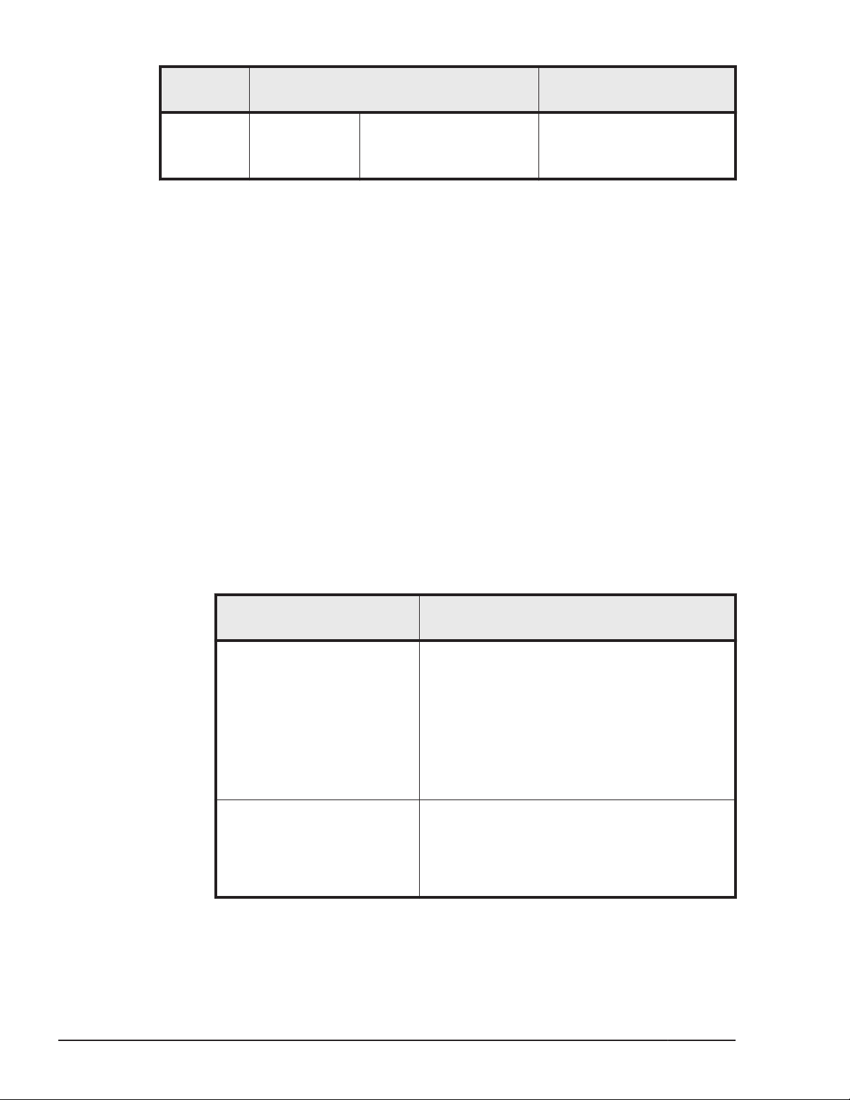
Configurati
on
Program Remarks
For details on how to use
ASM, refer to the
documentation for
Oracle RAC 11g.
#
You must apply MP3 or later.
Note
• When a host and an Oracle RAC 11g voting disk are connected by
multiple paths, HDLM performs failover processing for those paths (in the
same way as for normal paths) when an I/O timeout occurs for one of the
paths.
Note that, depending on the settings of Oracle RAC 11g, Oracle RAC 10g
might determine that a node error has occurred before the failover
processing performed by HDLM is completed, and then re-configure the
cluster.
Therefore, when HDLM manages the paths that are connected to an
Oracle RAC 11g voting disk, change settings as described below.
¢
Change the value of MISSCOUNT to match the type of storage system.
To do so, use the following table to obtain the value to be specified,
and then change the current value to a value equal to or greater than
the value you have obtained.
Table 3-15 Formula for Calculating MISSCOUNT
Storage system type
• Lightning 9900V series
• Hitachi USP series
• Universal Storage
Platform V/VM series
• Virtual Storage Platform
series
• VSP G1000 series
• HUS VM
• Hitachi
AMS2000/AMS/WMS/SMS
series
• HUS100 series
• Thunder 9500V series
Formula for obtaining the value of
MISSCOUNT
number-of-paths-connected-to-the-voting-disk
x 60 seconds
number-of-paths-connected-to-the-voting-disk
x 30 seconds
3-32
In addition to the value of MISSCOUNT shown above, also change the
value of DISKTIMEOUT. As with MISSCOUNT, the value to be specified in
DISKTIMEOUT is determined by the type of storage system. To make
Creating an HDLM Environment
Hitachi Dynamic Link Manager (for Solaris) User Guide
Page 99

the change, use the following table to obtain the value to be specified,
and then change the current value to a value equal to or greater than
the value you have obtained.
Table 3-16 Formula for Calculating DISKTIMEOUT
Number
of paths
Storage system type
connecte
d to the
voting
disk
Formula for obtaining the value of
DISKTIMEOUT
• Lightning 9900V series
• Hitachi USP series
• Universal Storage
Platform V/VM series
• Virtual Storage Platform
series
• VSP G1000 series
• HUS VM
• Hitachi
AMS2000/AMS/WMS/SM
S series
• HUS100 series
• Thunder 9500V series
3 or less You do not need to change the value
of DISKTIMEOUT.
4 or more number-of-paths-connected-to-the-
voting-disk x 60 seconds
6 or less You do not need to change the value
of DISKTIMEOUT.
7 or more number-of-paths-connected-to-the-
voting-disk x 30 seconds
For details on how to change MISSCOUNT and DISKTIMEOUT, contact
the company with which you have a contract for Oracle Support
Services.
Note that when you remove HDLM from the above configuration, you
must reset the values of MISSCOUNT and DISKTIMEOUT to their original
values. Therefore, make a note of the original values of MISSCOUNT
and DISKTIMEOUT before changing them.
• In Oracle RAC 11g, for the following devices, device name should be
matching between the nodes:
¢
voting disk
¢
Oracle Cluster Registry
¢
Oracle database file
¢
system table area
¢
users table area
¢
ASM disk to be used for ASM disk group creation
In an environment where an HDLM raw device is used as the devices
listed above, if the HDLM raw device name does not match between the
nodes, create an alias device file of the HDLM raw device in each node by
using the following procedure and set the created alias device file in
Oracle RAC 11g.
Creating an HDLM Environment
3-33
Hitachi Dynamic Link Manager (for Solaris) User Guide
Page 100

a. Check the major number and minor number of HDLM raw devices
used by Oracle RAC 11g by executing the following command in each
node:
# ls -lL HDLM-raw-device-file
Execution example:
# ls -lL /dev/rdsk/c10t50060E8005271760d5s0
crw-r----- 1 root sys 307, 1608 date/time /dev/rdsk/
c10t50060E8005271760d5s0
#
In this example, the major number is 307 and the minor number is
1608.
b. Create an alias device file by executing the following command in
each node. An alias device file corresponding to one disk slice should
have the same name in all the nodes.
# mknod /dev/alias-device-file c major-number minor-number
Note:
The name of the alias device file should not be duplicated with a
device file name created under the /dev directory by Solaris or other
drivers.
Execution example:
# mknod /dev/crs_ocr1 c 307 1608
#
In this example, a device file for RAC whose major number is 307 and
minor number is 1608 is created.
c. For the created alias device file, set the owner, group, and access
permission mode by using the following command. The owner, group,
and access permission mode to be set differs depending on the usage
purpose of Oracle RAC 11g corresponding to that device. For details
on this point, refer to the Oracle documentation.
# chmod mode /dev/alias-device-file
# chown owner:group /dev/alias-device-file
Execution example:
# chmod 640 /dev/crs_ocr1
# chown root:oinstall /dev/crs_ocr1
#
d. Execute the following command for the created alias device file and
check that the major number, minor number, owner, group, and
access permission mode is properly set:
# ls -l /dev/alias-device-file
Execution example:
# ls -l /dev/crs_ocr1
crw-r----- 1 root oinstall 307, 1608 date/time /dev/crs_ocr1
#
3-34
Creating an HDLM Environment
Hitachi Dynamic Link Manager (for Solaris) User Guide
 Loading...