

Page 1

Hitachi Dynamic Link Manager Software
User's Guide (for Linux(R))
3000-3-F04-60(E)
Page 2

Relevant program products
Hitachi Dynamic Link Manager version 6.6.2
For details about applicable OSs, see the Release Notes.
Trademarks
AIX is a trademark of International Business Machines Corporation in the United States, other countries, or both.
AMD, AMD Opteron, and combinations thereof, are trademarks of Advanced Micro Devices, Inc.
Brocade is a trademark or a registered trademark of Brocade Communications Systems, Inc. in the United States and/or in other
countries.
Emulex is a registered trademark of Emulex Corporation.
HP-UX is a product name of Hewlett-Packard Company.
HP StorageWorks is a trademark of Hewlett-Packard Company.
Intel Xeon is a trademark of Intel Corporation in the United States and other countries.
Itanium is a trademark of Intel Corporation in the United States and other countries.
Java is a registered trademark of Oracle and/or its affiliates.
JDK is either a registered trademark or a trademark of Oracle and/or its affiliates.
Linux(R) is the registered trademark of Linus Torvalds in the U.S. and other countries.
Microsoft is either a registered trademark or a trademark of Microsoft Corporation in the United States and/or other countries.
Oracle and Oracle9i are either registered trademarks or trademarks of Oracle and/or its affiliates.
Oracle and Oracle Database 10g are either registered trademarks or trademarks of Oracle and/or its affiliates.
Oracle and Oracle Database 11g are either registered trademarks or trademarks of Oracle and/or its affiliates.
Pentium is a trademark of Intel Corporation in the United States and other countries.
QLogic is a registered trademark of QLogic Corporation.
Red Hat is a trademark or a registered trademark of Red Hat Inc. in the United States and other countries.
Solaris is either a registered trademark or a trademark of Oracle and/or its affiliates.
SteelEye Technology, SteelEye and LifeKeeper are registered trademarks of SteelEye Technology, Inc.
Sun Microsystems is either a registered trademark or a trademark of Oracle and/or its affiliates.
SUSE is a registered trademark of Novell, Inc. in the United States and other countries.
UNIX is a registered trademark of The Open Group in the United States and other countries.
Veritas is a trademark or registered trademark of Symantec Corporation in the U.S. and other countries.
Windows is either a registered trademark or a trademark of Microsoft Corporation in the United States and/or other countries.
Throughout this document Hitachi has attempted to distinguish trademarks from descriptive terms by writing the name with the
capitalization used by the manufacturer, or by writing the name with initial capital letters. Hitachi cannot attest to the accuracy of
this information. Use of a trademark in this document should not be regarded as affecting the validity of the trademark.
Restrictions
Information in this document is subject to change without notice and does not represent a commitment on the part of Hitachi. The
software described in this manual is furnished according to a license agreement with Hitachi. The license agreement contains all of
the terms and conditions governing your use of the software and documentation, including all warranty rights, limitations of liability,
and disclaimers of warranty.
Material contained in this document may describe Hitachi products not available or features not available in your country.
No part of this material may be reproduced in any form or by any means without permission in writing from the publisher.
Edition history
3000-3-F04-60(E): August 2011
Copyright
All Rights Reserved. Copyright (C) 2008, 2011, Hitachi, Ltd.
Page 3

Summary of Amendments
The following table lists changes in this manual (3000-3-F04-60(E)) and product
changes related to this manual.
Changes Location in this manual
Systems that use an IP-SAN are now supported. 2.2, 2.2.2, 3.1.1, 3.1.2, 3.1.4, 3.1.5, 3.6.3, 3.6.6, 3.22.1,
The following messages have been added:
KAPL04053-W, KAPL05712-I,
KAPL10948-W, KAPL10949-E,
KAPL15001-I, KAPL15002-E,
KAPL15064-I, KAPL15065-E
Red Hat Enterprise Linux AS 4.9 and Red Hat
Enterprise Linux ES 4.9 are now supported.
It is now possible to specify the number of times
the same path can be used for I/O operations when
the Round Robin (
Blocks (
lbk) algorithm is used for load balancing.
rr), Least I/Os (lio), or Least
3.22.2, 4.6.4, 6.7.2, 7.2.3, 7.10.3, Appendix D
2.12.1, 8.4, 8.5, 8.10, 8.14
3.1.1, 3.1.3
4.3.7, 6.6.1, 6.6.2, 6.7.1, 6.7.2, 7.2.3, 7.10.3
In addition to the above changes, minor editorial corrections have been made.
Page 4

Page 5

Preface
This manual describes the functions and use of the following program products:
• Hitachi Dynamic Link Manager
Intended Readers
This manual is intended for system administrators who use Hitachi Dynamic Link
Manager (HDLM) to operate and manage storage systems. The readers of this manual
must have a basic knowledge of the following areas:
• Linux and its management functionality
• Storage system management functionality
• Cluster software functionality
• Volume management software functionality
Organization of This Manual
This manual is organized as follows:
1. Overview of HDLM
Chapter 1 gives an overview of HDLM, and describes its features.
2. HDLM Functions
Chapter 2 describes management targets and the system configuration of HDLM,
and the basic terms and functions for HDLM.
3. Creating an HDLM Environment
Chapter 3 describes the procedures for building an HDLM environment
(including installing and setting up HDLM), and describes for canceling the
settings.
4. HDLM Operation
Chapter 4 describes how to use HDLM by using both the HDLM commands, and
how to manually start and stop the HDLM manager. This chapter also describes
how to configure an environment to properly operate HDLM, such as changing
the HDLM management-target devices that connect paths or replacing the
hardware that makes up a path.
5. Troubleshooting
Chapter 5 explains how to troubleshoot a path error, HDLM failure, or any other
i
Page 6

problems that you might encounter.
6. Command Reference
Chapter 6 describes all the HDLM commands.
7. Utility Reference
Chapter 7 describes the HDLM utilities.
8. Messages
Chapter 8 provides information for all the possible messages that could be output
by HDLM. It also lists and explains the HDLM messages and shows the actions
to be taken in response to each message.
A. Notes on Linux Commands and Files
Appendix A gives notes on Linux commands and files.
B. Troubleshooting Products That Use the Weak-Modules Script
Appendix B explains how to deal with errors that are caused by installing or
uninstalling products that use the weak-modules script.
C. Functional Differences Between Versions of HDLM
Appendix C explains the differences in functionality between HDLM versions.
D. Glossary
This glossary explains terms used in this manual.
Related Publications
Manuals related to this manual are listed below. See these manuals when necessary:
• Hitachi Global Link Manager Software Installation and Configuration Guide
• Hitachi Global Link Manager Software Messages
• Hitachi Adaptable Modular Storage Series User's Guide
• Hitachi Simple Modular Storage Series User's Guide
• Hitachi USP Series User's Guide
• Hitachi Workgroup Modular Storage Series User's Guide
• Thunder9580V Series Disk Array Subsystem User's Guide
• Universal Storage Platform V Series User's Guide
• Universal Storage Platform VM Series User's Guide
• Virtual Storage Platform Series User's Guide
ii
Page 7

• HITACHI Gigabit Fibre Channel Board User's Guide
• ServerConductor/DeploymentManager User's Guide
Conventions: Abbreviations
This manual uses the following abbreviations for product names.
Abbreviation Full name or meaning
Device Manager Agent Device Manager Agent included in Hitachi Device Manager
Hitachi Global Link Manager Global Link Manager
HDLM Hitachi Dynamic Link Manager
Hitachi AMS A generic term for:
• Hitachi Adaptable Modular Storage 1000
• Hitachi Adaptable Modular Storage 500
• Hitachi Adaptable Modular Storage 200
Hitachi AMS/WMS series A generic term for:
• Hitachi Adaptable Modular Storage 1000
• Hitachi Adaptable Modular Storage 500
• Hitachi Adaptable Modular Storage 200
• Hitachi Workgroup Modular Storage series
Hitachi AMS2000/AMS/WMS/SMS series A generic term for:
• Hitachi Adaptable Modular Storage 2000 series
• Hitachi Adaptable Modular Storage 1000
• Hitachi Adaptable Modular Storage 500
• Hitachi Adaptable Modular Storage 200
• Hitachi Workgroup Modular Storage series
• Hitachi Simple Modular Storage series
Hitachi AMS2000 series Hitachi Adaptable Modular Storage 2000 series
Hitachi NSC55 Hitachi Network Storage Controller NSC55
Hitachi Simple Modular Storage series Hitachi SMS
Hitachi USP A generic term for:
• Hitachi NSC55
• Hitachi Universal Storage Platform 100
• Hitachi Universal Storage Platform 600
• Hitachi Universal Storage Platform 1100
• HP XP10000
• HP XP12000
• SVS
Hitachi WMS Hitachi Workgroup Modular Storage series
iii
Page 8

Abbreviation Full name or meaning
HP XP128 HP StorageWorks XP128 Disk Array
HP XP1024 HP StorageWorks XP1024 Disk Array
HP XP10000 HP StorageWorks XP10000 Disk Array
HP XP12000 HP StorageWorks XP12000 Disk Array
HP XP20000 HP StorageWorks XP20000 Disk Array
HP XP24000 HP StorageWorks XP24000 Disk Array
HP XP series A generic term for:
• HP XP128
• HP XP1024
• HP XP10000
• HP XP12000
• HP XP20000
• HP XP24000
HVM Hitachi Virtualization Manager
JDK
JRE
TM
JavaTM 2 SDK, Standard Edition
TM
2 Runtime Environment, Standard Edition
Java
Lightning 9900V series A generic term for:
• Lightning 9900V series
• HP XP128
• HP XP1024
Linux Linux(R)
LUKS Linux Unified Key Setup
Oracle9i RAC Oracle9i Real Application Clusters
Oracle Enterprise Linux 4 A generic term for:
• Oracle Enterprise Linux 4 Update 5
• Oracle Enterprise Linux 4 Update 6
Oracle Enterprise Linux 5 A generic term for:
• Oracle Enterprise Linux 5 Update 1
• Oracle Enterprise Linux 5 Update 4
• Oracle Enterprise Linux 5 Update 5
Oracle RAC 10g Oracle Real Application Clusters 10g
Oracle RAC 11g Oracle Real Application Clusters 11g
iv
Page 9

Abbreviation Full name or meaning
Oracle RAC A generic term for:
• Oracle9i Real Application Clusters
• Oracle Real Application Clusters 10g
• Oracle Real Application Clusters 11g
P9500 HP StorageWorks P9500 Disk Array
Red Hat Enterprise Linux A generic term for:
• Red Hat Enterprise Linux(R) AS4/ES4
• Red Hat Enterprise Linux(R) 5
• Red Hat Enterprise Linux(R) 6
Red Hat Enterprise Linux AS4/ES4 A generic term for:
• Red Hat Enterprise Linux(R) AS 4
• Red Hat Enterprise Linux(R) AS 4.5
• Red Hat Enterprise Linux(R) AS 4.6
• Red Hat Enterprise Linux(R) AS 4.7
• Red Hat Enterprise Linux(R) AS 4.8
• Red Hat Enterprise Linux(R) AS 4.9
• Red Hat Enterprise Linux(R) ES 4
• Red Hat Enterprise Linux(R) ES 4.5
• Red Hat Enterprise Linux(R) ES 4.6
• Red Hat Enterprise Linux(R) ES 4.7
• Red Hat Enterprise Linux(R) ES 4.8
• Red Hat Enterprise Linux(R) ES 4.9
Red Hat Enterprise Linux 5 A generic term for:
• Red Hat Enterprise Linux(R) 5
• Red Hat Enterprise Linux(R) 5 Advanced Platform
• Red Hat Enterprise Linux(R) 5.1
• Red Hat Enterprise Linux(R) 5.1 Advanced Platform
• Red Hat Enterprise Linux(R) 5.2
• Red Hat Enterprise Linux(R) 5.2 Advanced Platform
• Red Hat Enterprise Linux(R) 5.3
• Red Hat Enterprise Linux(R) 5.3 Advanced Platform
• Red Hat Enterprise Linux(R) 5.4
• Red Hat Enterprise Linux(R) 5.4 Advanced Platform
• Red Hat Enterprise Linux(R) 5.5
• Red Hat Enterprise Linux(R) 5.5 Advanced Platform
• Red Hat Enterprise Linux(R) 5.6
• Red Hat Enterprise Linux(R) 5.6 Advanced Platform
Red Hat Enterprise Linux 6 A generic term for:
• Red Hat Enterprise Linux(R) 6
• Red Hat Enterprise Linux(R) 6 Advanced Platform
RHCM Red Hat(R) Cluster Manager
v
Page 10

Abbreviation Full name or meaning
SUSE LINUX Enterprise Server A generic term for:
• SUSE LINUX(R) Enterprise Server 9
• SUSE LINUX(R) Enterprise Server 10
• SUSE LINUX(R) Enterprise Server 11
SVS HP StorageWorks 200 Storage Virtualization System
Thunder 9200 Hitachi Freedom Storage Thunder 9200
Universal Storage Platform V/VM A generic term for:
• Hitachi Universal Storage Platform V
• Hitachi Universal Storage Platform VM
• HP XP20000
• HP XP24000
UNIX A generic term for:
• AIX
• Solaris
• Linux
• HP-UX
VCS Veritas Cluster Server
Virtual Storage Platform A generic term for:
• Hitachi Virtual Storage Platform
• HP StorageWorks P9500 Disk Array
VxFS Veritas File System
VxVM Veritas Volume Manager
Note that if descriptions include the term Red Hat Enterprise Linux or Red Hat
Enterprise Linux AS4/ES4, and there is no specific explanation about Oracle
Enterprise Linux 4, read them as Oracle Enterprise Linux 4 when necessary. Similarly,
note that if descriptions include the term Red Hat Enterprise Linux or Red Hat
Enterprise Linux 5, and there is no specific explanation about Oracle Enterprise Linux
5, read them as Oracle Enterprise Linux 5 when necessary.
This manual also uses the following abbreviations.
Abbreviation Full name or meaning
API Application Programming Interface
BIOS Basic Input / Output System
CFQ Complete Fair Queuing
CHA Channel Adapter
vi
Page 11

Abbreviation Full name or meaning
CLPR Cache Logical Partition
CPU Central Processing Unit
CU Control Unit
DBMS Database Management System
Dev Device
DMI Desktop Management Interface
DNS Domain Name Server
DRBD Distributed Replicated Block Device
ELILO Extensible Firmware Interface Linux Loader
EM64T Extended Memory 64 Technology
EVMS Enterprise Volume Management System
ext Extended File System
FC Fibre Channel
FC-SP Fibre Channel Security Protocol
FO Failover
GMT Greenwich Mean Time
GRUB GRand Unified Bootloader
GUI Graphical User Interface
HBA Host Bus Adapter
HDev Host Device
HLU Host Logical Unit
HTTP Hypertext Transfer Protocol
I/O Input/Output
IA32 Intel Architecture 32
IDE Integrated Drive Electronics
IP Internet Protocol
IPC Inter Process Communication
vii
Page 12

Abbreviation Full name or meaning
IPF Itanium(R) Processor Family
IRQ Interrupt ReQuest
iSCSI Internet Small Computer System Interface
KVM Kernel-based Virtual Machine
LAN Local Area Network
LDAP Lightweight Directory Access Protocol
LDEV Logical Device
LILO Linux Loader
LU Logical Unit
LUN Logical Unit Number
LVM Logical Volume Manager
md Multiple Devices
NAS Network Attached Storage
NIC Network Interface Card
NTP Network Time Protocol
OS Operating System
PPort
PCI Peripheral Component Interconnect
RADIUS Remote Authentication Dial in User Service
SAN Storage Area Network
SCSI Small Computer System Interface
SLPR Storage Logical Partition
SMTP Simple Mail Transfer Protocol
SNMP Simple Network Management Protocol
SP Service Pack
SSL Secure Sockets Layer
SVP Service Processor
viii
Page 13

Abbreviation Full name or meaning
UUID Universally Unique Identifier
VG Volume Group
WWN World Wide Name
Conventions: Diagrams
This manual uses the following conventions in diagrams:
Conventions: Fonts and Symbols
Font and symbol conventions are classified as:
• General font conventions
• Conventions in syntax explanations
These conventions are described below.
General Font Conventions
The following table lists the general font conventions:
ix
Page 14

Font Convention
Bold Bold type indicates text on a window, other than the window title. Such text includes menus,
Italics Italics are used to indicate a placeholder for some actual text provided by the user or system.
Code font A code font indicates text that the user enters without change, or text (such as messages) output
menu options, buttons, radio box options, or explanatory labels. For example, bold is used in
sentences such as the following:
• From the File menu, choose Open.
• Click the Cancel button.
• In the Enter name entry box, type your name.
Italics are also used for emphasis. For example:
• Write the command as follows:
copy source-file target-file
• Do not delete the configuration file.
by the system. For example:
• At the prompt, enter
• Use the
• The following message is displayed:
send command to send mail.
The password is incorrect.
dir.
Code examples and messages appear as follows (though there may be some
exceptions, such as when the code is part of a diagram):
MakeDatabase
...
StoreDatabase temp DB32
In examples of coding, an ellipsis (...) indicates that one or more lines of coding are not
shown for purposes of brevity.
Conventions in Syntax Explanations
Syntax definitions appear as follows:
StoreDatabase [temp|perm] (database-name ...)
The following table lists the conventions used in syntax explanations:
Example font or symbol Convention
StoreDatabase Code-font characters must be entered exactly as shown.
database-name This font style marks a placeholder that indicates where appropriate characters are
SD Bold code-font characters indicate the abbreviation for a command.
perm Underlined characters indicate the default value.
x
to be entered in an actual command.
Page 15

Example font or symbol Convention
[ ] Square brackets enclose an item or set of items whose specification is optional. An
item that is underlined is specified when all items are omitted.
{ } One of the options enclosed in { } must be specified.
| Only one of the options separated by a vertical bar can be specified at the same
time.
... An ellipsis (...) indicates that the item or items enclosed in ( ) or [ ] immediately
() Parentheses indicate the range of items to which the vertical bar (|) or ellipsis (...)
# A prompt on a command-execution window when the OS is UNIX
preceding the ellipsis may be specified as many times as necessary.
is applicable.
Conventions: KB, MB, GB, and TB
This manual uses the following conventions:
• 1 KB (kilobyte) is 1,024 bytes.
• 1 MB (megabyte) is 1,024
• 1 GB (gigabyte) is 1,024
• 1 TB (terabyte) is 1,024
2
bytes.
3
bytes.
4
bytes.
xi
Page 16

Page 17

Contents
Preface i
Intended Readers........................................................................................................i
Organization of This Manual .....................................................................................i
Related Publications..................................................................................................ii
Conventions: Abbreviations.................................................................................... iii
Conventions: Diagrams............................................................................................ix
Conventions: Fonts and Symbols.............................................................................ix
Conventions: KB, MB, GB, and TB ........................................................................xi
1. Overview of HDLM 1
1.1 What is HDLM? .........................................................................................................2
1.2 HDLM Features..........................................................................................................4
2. HDLM Functions 5
2.1 Devices Managed by HDLM......................................................................................6
2.2 System Configuration.................................................................................................7
2.2.1 System Configuration Using an FC-SAN .......................................................7
2.2.2 System Configuration Using an IP-SAN ........................................................9
2.3 LU Configuration .....................................................................................................12
2.4 Program Configuration.............................................................................................14
2.5 Position of the HDLM Driver and HDLM Device...................................................16
2.6 Logical Device Files for HDLM Devices.................................................................17
2.7 Distributing a Load Using Load Balancing..............................................................19
2.7.1 Paths To Which Load Balancing Is Applied .................................................21
2.7.2 Load Balancing Algorithms ..........................................................................23
2.8 Performing Failovers and Failbacks Using Path Switching.....................................25
2.8.1 Automatic Path Switching.............................................................................25
2.8.2 Manual Path Switching .................................................................................28
2.8.3 Path Status Transition....................................................................................29
2.9 Monitoring Intermittent Errors (Functionality When Automatic Failback Is Used)32
2.9.1 Checking Intermittent Errors.........................................................................32
2.9.2 Setting Up Intermittent Error Monitoring .....................................................32
2.9.3 Intermittent Error Monitoring Actions..........................................................33
2.9.4 When a User Changes the Intermittent Error Information...........................35
2.10 Detecting Errors by Using Path Health Checking..................................................38
2.11 Error Management ..................................................................................................39
2.11.1 Types of Collected Logs..............................................................................41
2.11.2 Filtering of Error Information .....................................................................42
xiii
Page 18

2.11.3 Collecting Error Information Using the Utility for Collecting HDLM Error
Information (DLMgetras)............................................................................. 43
2.11.4 Utility for Collecting HDLM Installation Error Information
(installgetras)................................................................................................ 43
2.12 Collecting Audit Log Data..................................................................................... 44
2.12.1 Categories and Audit Events that HDLM Can Output to the Audit Log ... 45
2.12.2 Requirements for Outputting Audit Log Data............................................ 49
2.12.3 Destination and Filtering of Audit Log Data.............................................. 50
2.12.4 Audit Log Data Formats............................................................................. 51
2.13 Integrated HDLM management using Global Link Manager................................ 54
2.14 Cluster Support ...................................................................................................... 56
3. Creating an HDLM Environment 57
3.1 HDLM System Requirements.................................................................................. 58
3.1.1 Hosts and OSs Supported by HDLM ........................................................... 58
3.1.2 Storage Systems Supported by HDLM......................................................... 71
3.1.3 Related Products When Using Red Hat Enterprise Linux AS4/ES4............ 72
3.1.4 Related Products When Using Red Hat Enterprise Linux 5......................... 96
3.1.5 Related Products When Using Red Hat Enterprise Linux 6....................... 109
3.1.6 Related Products When Using SUSE LINUX Enterprise Server 9.............110
3.1.7 Related Products When Using SUSE LINUX Enterprise Server 10...........111
3.1.8 Related Products When Using SUSE LINUX Enterprise Server 11 ...........118
3.1.9 Related Products When Using Oracle Enterprise Linux 4 ......................... 120
3.1.10 Related Products When Using Oracle Enterprise Linux 5 ....................... 121
3.1.11 Memory and Disk Capacity Requirements............................................... 124
3.1.12 Number of Paths Supported in HDLM..................................................... 127
3.1.13 Virtual Environments Supported by HDLM ............................................ 127
3.2 Flow for Creating an HDLM Environment ........................................................... 129
3.3 HDLM Installation Types ...................................................................................... 131
3.4 Knowledge Required Before You Install HDLM .................................................. 132
3.5 Notes on Creating an HDLM Environment........................................................... 133
3.5.1 Notes on Hardware Settings ....................................................................... 133
3.5.2 Notes on Linux ........................................................................................... 134
3.5.3 Notes on Installing HDLM......................................................................... 135
3.5.4 Notes on an Upgrade Installation or Re-installation of HDLM ................. 137
3.5.5 Notes on a Device Manager Agent............................................................. 137
3.6 Installing HDLM................................................................................................... 139
3.6.1 Preparations for a New Installation of HDLM ........................................... 139
3.6.2 Performing a New Installation of HDLM................................................... 144
3.6.3 Preparations for an Upgrade Installation or Re-installation of HDLM...... 151
3.6.4 Performing a Re-installation of HDLM...................................................... 152
3.6.5 Performing an Upgrade Installation of HDLM .......................................... 159
3.6.6 Unattended Installation of HDLM.............................................................. 165
3.7 Installing HDLM for Managing Boot Disks.......................................................... 172
xiv
Page 19

3.7.1 Notes on Installing HDLM in a Boot Disk Environment............................172
3.7.2 Overview of the Procedure for Installing HDLM in a Boot Disk
Environment................................................................................................175
3.7.3 Settings for Using an HDLM Device as a Boot Disk .................................177
3.7.4 Upgrade Installation in an Environment Where an HDLM Device Is Used as
a Boot Disk .................................................................................................188
3.7.5 Settings for Using a Logical Volume (LVM2) on an HDLM Device as a Boot
Disk .............................................................................................................197
3.7.6 Upgrade Installation in an Environment Where a Logical Volume (LVM2) on
an HDLM Device Is Used as a Boot Disk..................................................209
3.7.7 Countermeasures for Unsuccessful Startup of the OS from an HDLM
Device .........................................................................................................226
3.8 Settings for LUKS ..................................................................................................229
3.8.1 Notes on Using LUKS.................................................................................229
3.8.2 Using HDLM in an LUKS Environment ....................................................229
3.9 Settings for md Devices..........................................................................................232
3.9.1 Notes on Setting Up md Devices ................................................................232
3.9.2 Creating an md Device................................................................................233
3.9.3 Using HDLM in an md Device Environment .............................................237
3.10 Settings for LVM2 ................................................................................................246
3.10.1 Notes on Using LVM2 ..............................................................................246
3.10.2 When Using an HDLM Device to Create a New Logical Volume ...........246
3.10.3 When Moving a Logical Volume Created on a SCSI Device in a Single-Path
Environment to an HDLM Device..............................................................253
3.11 Settings for Xen....................................................................................................258
3.12 Settings for KVM .................................................................................................260
3.13 Settings for Heartbeat...........................................................................................262
3.14 Settings for Oracle RAC.......................................................................................263
3.15 Settings for the RHCM.........................................................................................266
3.15.1 Notes on Using RHCM .............................................................................266
3.15.2 When Using Red Hat Enterprise Linux AS4/ES4.....................................266
3.15.3 When Using Red Hat Enterprise Linux 5, or Red Hat Enterprise Linux
6...................................................................................................................267
3.16 Settings for VCS...................................................................................................268
3.17 Checking the Path Configuration .........................................................................269
3.18 Setting Up HDLM ................................................................................................271
3.18.1 Checking the Current Settings...................................................................271
3.18.2 Setting Up the HDLM Functions ..............................................................271
3.18.3 Checking the Updated Settings .................................................................280
3.19 The Process-specific-trace Information File.........................................................281
3.19.1 Notes on Using the Hitachi Network Objectplaza Trace Library .............281
3.20 Creating a Character-Type Device File for an HDLM Device.............................282
3.20.1 When Using Red Hat Enterprise Linux 5 or Red Hat Enterprise Linux 6 282
xv
Page 20

3.20.2 When Using Red Hat Enterprise Linux AS4/ES4 or SUSE LINUX Enterprise
Server ......................................................................................................... 282
3.21 Creating File Systems for HDLM (When Volume Management Software Is Not
Used)..................................................................................................................... 284
3.21.1 Mounting a File System............................................................................ 284
3.21.2 Creating a File System.............................................................................. 284
3.22 Settings for Automatic Mounting ........................................................................ 286
3.22.1 Setting the HDLM Device for the First Time........................................... 286
3.22.2 Migrating from an Environment Where a SCSI Device Is Already Set... 287
3.23 Canceling the Settings for HDLM....................................................................... 290
3.23.1 Operations on HDLM-Managed Devices................................................. 290
3.23.2 Canceling the Heartbeat Settings.............................................................. 292
3.23.3 Canceling the Settings for Oracle RAC.................................................... 292
3.23.4 Canceling the Settings for RHCM............................................................ 293
3.23.5 Canceling the Settings for VCS................................................................ 295
3.23.6 Canceling the Xen Settings....................................................................... 295
3.23.7 Canceling the KVM Settings.................................................................... 297
3.23.8 Canceling the Settings for LVM2 ............................................................. 298
3.23.9 Canceling the md Device Settings............................................................ 302
3.23.10 Canceling the LUKS Settings................................................................. 310
3.23.11 Uninstalling HDLM.................................................................................311
3.23.12 Uninstalling Hitachi Network Objectplaza Trace Library (HNTRLib2) 326
4. HDLM Operation 329
4.1 Notes on Using HDLM.......................................................................................... 330
4.1.1 Notes Common to OSs ............................................................................... 330
4.1.2 Notes When Using Red Hat Enterprise Linux AS4/ES4, or Oracle Enterprise
Linux 4 ....................................................................................................... 332
4.1.3 Notes When Using Red Hat Enterprise Linux 5, Red Hat Enterprise Linux 6,
or Oracle Enterprise Linux 5...................................................................... 333
4.1.4 Notes When Using SUSE LINUX Enterprise Server 9.............................. 334
4.1.5 Notes When Using SUSE LINUX Enterprise Server 10............................ 335
4.1.6 Notes When Using SUSE LINUX Enterprise Server 11............................ 336
4.2 Updating Kernel Packages and Applying OS Update Packages ........................... 339
4.2.1 Environment Where an HDLM Device Is not Used as the Boot Disk....... 339
4.2.2 Environment Where an HDLM Device Is Used as the Boot Disk ............. 339
4.2.3 Environment Where a Logical Volume (LVM2) on an HDLM Device Is Used
as the Boot Disk ......................................................................................... 340
4.3 HDLM Operations Using Commands ................................................................... 341
4.3.1 Notes on Using Commands ........................................................................ 341
4.3.2 Viewing Path Information .......................................................................... 341
4.3.3 Changing the Status of Paths ...................................................................... 341
4.3.4 Viewing LU Information ............................................................................ 343
xvi
Page 21

4.3.5 Displaying Corresponding Information About an HDLM Device, SCSI
Device, and LDEV......................................................................................344
4.3.6 Initializing Statistical Information for Paths ...............................................345
4.3.7 Viewing and Setting Up the Operating Environment..................................346
4.3.8 Viewing License Information......................................................................348
4.3.9 Updating the License...................................................................................348
4.3.10 Viewing HDLM Version Information .......................................................349
4.3.11 Viewing HDLM Component Information .................................................350
4.4 Starting and Stopping the HDLM Manager............................................................352
4.4.1 Starting the HDLM Manager ......................................................................352
4.4.2 Stopping the HDLM Manager.....................................................................353
4.5 HDLM Resident Processes.....................................................................................355
4.6 Reconfiguring the HDLM Operating Environment................................................356
4.6.1 Replacing HBAs..........................................................................................356
4.6.2 Replacing a Fiber Cable..............................................................................364
4.6.3 Replacing the Fibre Channel Switch...........................................................367
4.6.4 Changing the HDLM Device Configuration...............................................369
4.6.5 About Creating a New HDLM Device........................................................383
4.6.6 Note on adding a BladeSymphony I/O drawer ...........................................385
5. Troubleshooting 387
5.1 Information Collected by the DLMgetras Utility for Collecting HDLM Error
Information............................................................................................................388
5.2 Checking Error Information in Messages...............................................................389
5.3 What To Do for a Path Error ..................................................................................391
5.3.1 Examining the Messages.............................................................................392
5.3.2 Obtain Path Information..............................................................................392
5.3.3 Identifying the Error Path............................................................................393
5.3.4 Narrowing Down the Hardware That Might Have Caused the Error .........393
5.3.5 Identifying the Error Location and Correcting any Hardware Error...........393
5.3.6 Placing the Path Online...............................................................................393
5.4 What To Do for a Program Error............................................................................394
5.4.1 Examining the Messages.............................................................................394
5.4.2 Obtaining Program Information..................................................................394
5.4.3 What To Do for the Program Error .............................................................395
5.4.4 Contacting your HDLM Vendor or Maintenance Company .......................395
5.5 What To Do for Other Errors..................................................................................396
6. Command Reference 397
6.1 Overview of the HDLM Command dlnkmgr .........................................................398
6.2 clear (Returns the Path Statistics to the Initial Value) ............................................400
6.2.1 Format .........................................................................................................400
6.2.2 Parameters ...................................................................................................400
6.3 help (Displays the Operation Format) ....................................................................402
xvii
Page 22

6.3.1 Format......................................................................................................... 402
6.3.2 Parameter.................................................................................................... 402
6.4 offline (Places Paths Offline)................................................................................. 404
6.4.1 Format......................................................................................................... 404
6.4.2 Parameters .................................................................................................. 404
6.5 online (Places Paths Online).................................................................................. 409
6.5.1 Format......................................................................................................... 409
6.5.2 Parameters .................................................................................................. 409
6.6 set (Sets Up the Operating Environment) .............................................................. 414
6.6.1 Format......................................................................................................... 414
6.6.2 Parameters .................................................................................................. 414
6.7 view (Displays Information).................................................................................. 431
6.7.1 Format......................................................................................................... 431
6.7.2 Parameters (To display program information)............................................ 432
7. Utility Reference 463
7.1 Overview of the Utilities........................................................................................ 464
7.2 DLMgetras Utility for Collecting HDLM Error Information................................ 466
7.2.1 Format......................................................................................................... 466
7.2.2 Parameters .................................................................................................. 466
7.2.3 List of Collected Error Information............................................................ 468
7.3 dlmcfgmgr Utility for Managing the HDLM Configuration ................................. 489
7.3.1 Format......................................................................................................... 489
7.3.2 Parameters .................................................................................................. 489
7.4 dlmmkinitrd Utility for Supporting a Boot Disk ................................................... 500
7.4.1 Format......................................................................................................... 500
7.4.2 Parameters .................................................................................................. 500
7.5 dlmpr Utility for Clearing HDLM Persistent Reservation..................................... 503
7.5.1 Format......................................................................................................... 503
7.5.2 Parameters .................................................................................................. 503
7.6 dlmsetopt Utility for Setting HDLM Driver Options ............................................ 506
7.6.1 Format......................................................................................................... 506
7.6.2 Parameters .................................................................................................. 506
7.7 dlmstart Utility for Starting HDLM....................................................................... 510
7.7.1 Format......................................................................................................... 510
7.8 dlmupdatesysinit Utility for Updating System Scripts ...........................................511
7.8.1 Format..........................................................................................................511
7.9 installgetras Utility for Collecting HDLM Installation Error Information............ 512
7.9.1 Format......................................................................................................... 512
7.9.2 Parameters .................................................................................................. 512
7.9.3 Error Information To Be Collected............................................................. 512
7.10 installhdlm Utility for Installing HDLM ............................................................. 514
7.10.1 Format....................................................................................................... 514
7.10.2 Parameters ................................................................................................ 514
xviii
Page 23

7.10.3 Editing an Installation-Information Settings File......................................514
7.11 installux.sh Utility for HDLM Common Installer................................................521
7.11.1 Format .......................................................................................................521
7.11.2 Parameters .................................................................................................521
7.11.3 Log file ......................................................................................................521
8. Messages 523
8.1 Before Viewing the List of Messages.....................................................................524
8.1.1 Format and Meaning of Message IDs .........................................................524
8.1.2 Terms Used in Messages and Message Explanations .................................524
8.1.3 Components That Output Messages to syslog ............................................524
8.2 KAPL01001 to KAPL02000 ..................................................................................526
8.3 KAPL03001 to KAPL04000 ..................................................................................548
8.4 KAPL04001 to KAPL05000 ..................................................................................551
8.5 KAPL05001 to KAPL06000 ..................................................................................560
8.6 KAPL06001 to KAPL07000 ..................................................................................567
8.7 KAPL07001 to KAPL08000 ..................................................................................571
8.8 KAPL08001 to KAPL09000 ..................................................................................572
8.9 KAPL09001 to KAPL10000 ..................................................................................575
8.10 KAPL10001 to KAPL11000 ................................................................................602
8.11 KAPL11001 to KAPL12000 ................................................................................640
8.12 KAPL12001 to KAPL13000 ................................................................................644
8.13 KAPL13001 to KAPL14000 ................................................................................662
8.14 KAPL15001 to KAPL16000 ................................................................................677
8.15 Return Codes for Hitachi Command Suite Common Agent Component.............684
Appendixes 691
A. Notes on Linux Commands and Files......................................................................692
A.1 Notes on the /proc/partitions File..................................................................692
A.2 Notes on Linux Commands...........................................................................692
A.3 Notes on the iostat Command .......................................................................693
A.4 Notes on the mkfs Command ........................................................................694
A.5 Notes on the fdisk Command ........................................................................694
A.6 Notes on the sar Command ...........................................................................695
A.7 Notes on the fdisk and parted Commands.....................................................695
A.8 Notes on the parted Command ......................................................................695
A.9 Notes on the vgrename and lvrename Commands ........................................696
B. Troubleshooting Products That Use the Weak-Modules Script...............................697
B.1 Installing Products That Use the Weak-Modules Script................................697
B.2 Uninstalling Products That Use the Weak-Modules Script ...........................702
C. Functional Differences Between Versions of HDLM..............................................703
C.1 Functional Differences Between Version 6.2.1 and Versions Earlier Than
6.2.1...............................................................................................................703
C.2 Functional Differences Between Version 6.1 and Versions Earlier Than 6.1703
xix
Page 24

C.3 Functional Differences Between Version 6.0 or Later and Versions Earlier Than
6.0................................................................................................................. 703
C.4 Functional Differences Between Version 5.9.4 or Later and Versions Earlier
Than 5.9.4..................................................................................................... 703
C.5 Functional Differences Between Version 5.9.1 or Later and Versions Earlier
Than 5.9.1..................................................................................................... 704
C.6 Functional Differences Between Version 5.9 or Later and Versions Earlier Than
5.9................................................................................................................. 704
C.7 Functional Differences Between Version 5.8 or Later and Versions Earlier Than
5.8................................................................................................................. 704
C.8 Functional Differences Between Version 5.7.1 or Later and Versions Earlier
Than 5.7.1..................................................................................................... 705
C.9 Functional Differences Between Version 5.7.0-01 or Later and Versions Earlier
Than 5.7.0-01 ............................................................................................... 705
C.10 Functional Differences Between Version 5.7 or Later and Versions Earlier
Than 5.7........................................................................................................ 705
C.11 Functional Differences Between Version 5.6.3 or Later and Versions Earlier
Than 5.6.3..................................................................................................... 706
C.12 Functional Differences Between Version 5.4 or Later and Versions Earlier
Than 5.4........................................................................................................ 706
D. Glossary .................................................................................................................. 707
Index 715
xx
Page 25

Chapter
1. Overview of HDLM
HDLM is a software package that manages paths between a host and a storage system.
HDLM is designed to distribute loads across multiple paths and will switch a given
load to another path if there is a failure in the path that is currently being used, thus
improving system reliability.
This chapter gives an overview of HDLM and describes its features.
1.1 What is HDLM?
1.2 HDLM Features
1
Page 26
1. Overview of HDLM
1.1 What is HDLM?
With the widespread use of data warehousing and increasing use of multimedia data,
the need for high-speed processing of large volumes of data on networks has rapidly
grown. To satisfy this need, networks dedicated to the transfer of data, such as SANs,
are now being used to provide access to storage systems.
HDLM manages the access paths to these storage systems. HDLM provides the ability
to distribute loads across multiple paths and switch to another path if there is a failure
in the path that is currently being used, thus improving system availability and
reliability.
Figure 1-1: Between Hosts and Storage Systems illustrates the connections between
various hosts and storage systems. A server on which HDLM is installed is called a
host.
Figure 1-1: Between Hosts and Storage Systems
HDLM supports the following storage systems:
• Hitachi AMS2000/AMS/WMS/SMS series
• Hitachi USP
• Lightning 9900 series
2
Page 27

• Lightning 9900V series
• Thunder 9500V series
• Universal Storage Platform V/VM
• Virtual Storage Platform
1. Overview of HDLM
3
Page 28

1. Overview of HDLM
1.2 HDLM Features
HDLM features include the following:
The ability to distribute a load across multiple paths. This is also known as load
balancing.
When a host is connected to a storage system via multiple paths, HDLM can
distribute the load across all the paths. This prevents one, loaded down path from
affecting the processing speed of the entire system.
For details on load balancing, see 2.7 Distributing a Load Using Load Balancing.
The ability to continue running operations between a host and storage system, even if
there is a failure. This is also known as performing a failover.
When a host is connected to a storage system via multiple paths, HDLM can
automatically switch to another path if there is some sort of failure in the path that
is currently being used. This allows operations to continue between a host and a
storage system.
For details on performing failovers, see 2.8 Performing Failovers and Failbacks
Using Path Switching.
The ability to bring a path that has recovered from an error back online. This is also
known as performing a failback.
If a path is recovered from an error, HDLM can bring that path back online. This
enables the maximum possible number of paths to always be available and online,
which in turn enables HDLM to better distribute the load across multiple paths.
Failbacks can be performed manually or automatically. In an automatic failback,
HDLM will automatically restore the path to an active state after the user has
corrected the problem that exists on the physical path.
For details on performing failbacks, see 2.8 Performing Failovers and Failbacks
Using Path Switching.
The ability to automatically check the status of any given path at regular intervals. This
is also known as path health checking.
HDLM can easily detect errors by checking the statuses of paths at user-defined
time intervals. This allows you to check for any existing path errors and to resolve
them promptly and efficiently.
For details on setting up and performing path health checking, see 2.10 Detecting
Errors by Using Path Health Checking.
4
Page 29

Chapter
2. HDLM Functions
This chapter describes the various functions that are built into HDLM. Before the
function specifications are explained though, this chapter will go into detail about the
HDLM management targets, system configuration, and basic terms that are necessary
to know to effectively operate HDLM. After that, the rest of the chapter focus on
describing all the HDLM functions, including the main ones: load distribution across
paths and path switching.
2.1 Devices Managed by HDLM
2.2 System Configuration
2.3 LU Configuration
2.4 Program Configuration
2.5 Position of the HDLM Driver and HDLM Device
2.6 Logical Device Files for HDLM Devices
2.7 Distributing a Load Using Load Balancing
2.8 Performing Failovers and Failbacks Using Path Switching
2.9 Monitoring Intermittent Errors (Functionality When Automatic Failback Is
Used)
2.10 Detecting Errors by Using Path Health Checking
2.11 Error Management
2.12 Collecting Audit Log Data
2.13 Integrated HDLM management using Global Link Manager
2.14 Cluster Support
5
Page 30

2. HDLM Functions
2.1 Devices Managed by HDLM
Below is a list of devices that can or cannot be managed by HDLM. The devices that
can be managed by HDLM are called HDLM management-target devices.
HDLM management-target devices:
The following devices of the storage systems listed in Section 1.1 What is
HDLM?:
• SCSI devices
• Boot disks
Non-HDLM management-target devices:
• SCSI devices other than those of the storage systems listed in Section
1.1 What is HDLM?
• Devices other than disks (such as tape devices)
• Command devices of the storage systems listed in Section 1.1 What is
HDLM? (For example, Hitachi RAID Manager command devices.)
6
Page 31

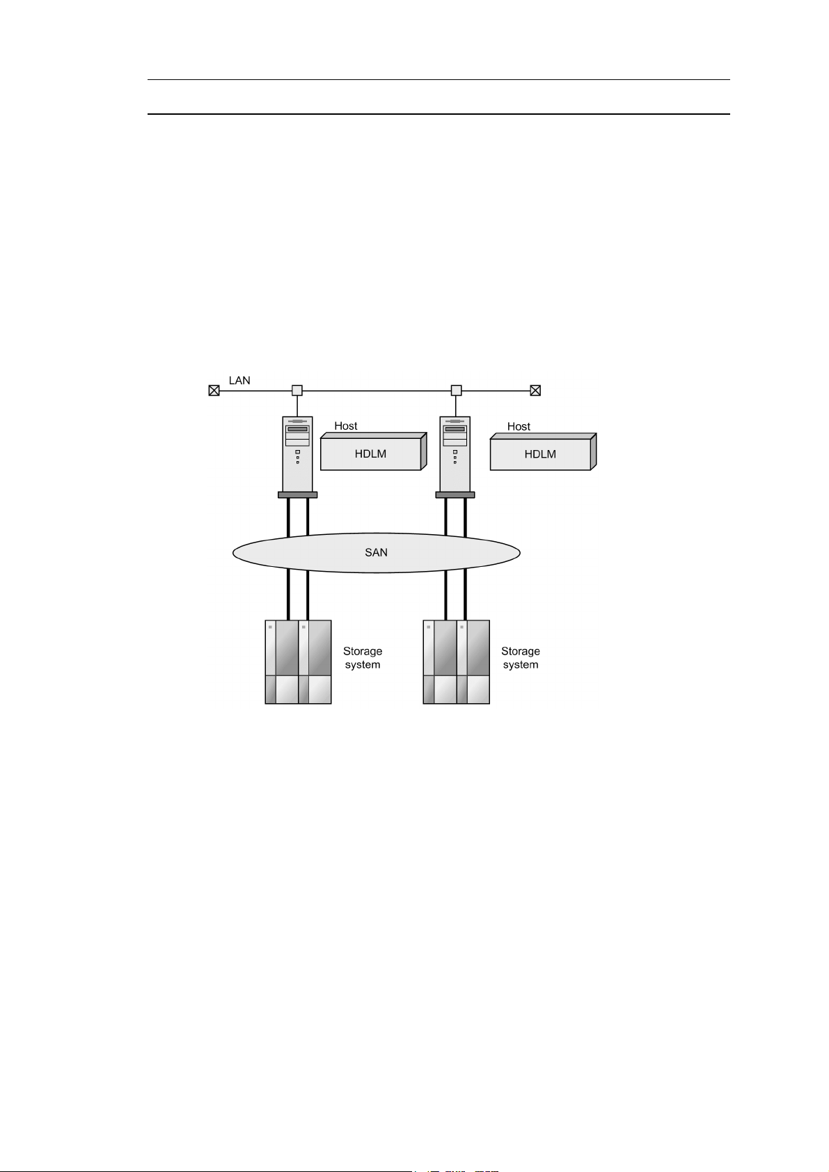
2.2 System Configuration
HDLM manages routes between a host and a storage system by using the SCSI driver.
A host and a storage system are connected via an FC-SAN or an IP-SAN.
2.2.1 System Configuration Using an FC-SAN
In an FC-SAN, fiber cables connect hosts to storage systems. The cable port on the
host is a host bus adapter (HBA). The cable port on the storage system is a port (P) on
a channel adapter (CHA).
A logical unit (LU) contained in a storage system is the target of input to, or output
from, the host. You can divide an LU into multiple areas. Each area after the division
is called a Dev. The Dev is equivalent to a partition. A route that connects a host and
an LU is called a physical path, and a route that connects a host and a Dev is called a
path. When an LU has been divided into multiple Devs, the number of paths set to the
LU is equal to the number that is found by multiplying the number of physical paths
by the number of Devs in the LU.
HDLM assigns an ID to a physical path and manages the paths on a physical-path
basis. When you use HDLM, there is no need to consider the difference between a
physical path and a path. Thus, hereafter both physical paths and paths might be called
paths, without a distinction being made between the two. The ID that HDLM assigns
for each physical path is called an AutoPATH_ID. Also, a path might be called a
management target.
2. HDLM Functions
Figure 2-1: Configuration of an HDLM System When Using an FC-SAN shows the
configuration of an HDLM system using an FC-SAN.
7
Page 32

2. HDLM Functions
Figure 2-1: Configuration of an HDLM System When Using an FC-SAN
Table 2-1: HDLM System Components When Using an FC-SAN lists the HDLM
system components when using an FC-SAN.
Tabl e 2 -1 : HDLM System Components When Using an FC-SAN
Components Description
HBA A host bus adapter. This serves as a cable port on the host.
FC-SAN A dedicated network that is used for data transfer between the host and storage systems.
CHA A channel adapter.
P A port on a CHA. This serves as a cable port on a storage system.
LU A logical unit (a logical volume defined on the storage system). This serves as the target of input
or output operations from the host.
Dev An area (partition) of a divided LU.
Physical path A route that connects a host and an LU.
8
Page 33

Components Description
Path A route that connects a host and a Dev.
2.2.2 System Configuration Using an IP-SAN
In an IP-SAN, LAN cables are used to connect hosts to storage systems. The cable port
on the host is called a network interface card (NIC). In order to use an NIC, the iSCSI
software must be installed ahead of time on the host. The cable port on the storage
system is called a port (P) on a channel adapter (CHA) used for iSCSI connections.
A logical unit (LU) contained in a storage system is the target of input to, or output
from, the host. You can divide an LU into multiple areas. Each area after the division
is called a Dev. The Dev is equivalent to a partition. A route that connects a host and
an LU is called a physical path, and a route that connects a host and a Dev is called a
path. When an LU has been divided into multiple Devs, the number of paths set to the
LU is equal to the number that is found by multiplying the number of physical paths
by the number of Devs in the LU.
HDLM assigns an ID to a physical path and manages the paths on a physical-path
basis. When you use HDLM, there is no need to consider the difference between a
physical path and a path. Thus, hereafter both physical paths and paths might be called
paths, without a distinction being made between the two. The ID that HDLM assigns
for each physical path is called an AutoPATH_ID. Also, a path might be called a
management target.
2. HDLM Functions
Figure 2-2: Configuration of an HDLM System When Using an IP-SAN shows the
configuration of an HDLM system using an IP-SAN.
9
Page 34

2. HDLM Functions
Figure 2-2: Configuration of an HDLM System When Using an IP-SAN
Table 2-2: HDLM System Components When Using an IP-SAN lists the HDLM
system components when using an IP-SAN.
Tabl e 2 -2 : HDLM System Components When Using an IP-SAN
Components Description
iSCSI software The driver software that contains the iSCSI initiator function
NIC A network interface card that serves as a cable port on a host. The NIC is referred to as the
HBA in HDLM commands. Sometimes, it is also just simply called an HBA in this manual.
IP-SAN A data transfer network that connects hosts and storage systems by using the iSCSI standard.
CHA A channel adapter.
P A port on a CHA. This serves as a cable port on a storage system.
LU A logical unit (a logical volume defined on the storage system). This serves as the target of
Dev An area (partition) of a divided LU.
10
input or output operations from the host.
Page 35

Components Description
Physical path A route that connects a host and an LU.
Path A route that connects a host and a Dev.
IP-SAN environments supported by HDLM
HDLM supports system configurations that use an IP-SAN in the following
environments:
• OS
• Red Hat Enterprise Linux 5.6
• Red Hat Enterprise Linux 5.6 Advanced Platform
• Red Hat Enterprise Linux 6
• iSCSI software
2. HDLM Functions
HDLM supports the iSCSI initiator (
iscsi-initiator-utils) supplied with
the OS.
• NICs
For details on the applicable NICs, see HDLM Release Notes.
• Storage system
The storage system applicable for an IP-SAN is a Hitachi AMS2000 series
storage system.
Restrictions on using HDLM in an IP-SAN environment
The following restrictions apply when using HDLM in an IP-SAN environment:
• Use of HDLM in cluster configurations or boot disk environments is not
supported.
• The kdump function cannot be used.
11
Page 36

2. HDLM Functions
2.3 LU Configuration
After you have properly installed HDLM, the LU configuration will change as follows:
Before the installation of HDLM:
The host recognizes that a SCSI device is connected to each path.
Thus, a single LU in the storage system is recognized as though there are as many
LUs as there are paths.
After the installation of HDLM:
An HDLM device corresponding one-to-one with an LU in the storage system is
created at a level higher than the SCSI device.
Thus, from the host, LUs in the storage system are also recognized as a single LU
regardless of the number of paths.
#
In addition to the one that indicates the entire LU, a logical device file for the
HDLM device is created for each partition.
An LU recognized by a host after HDLM installation, is called a host LU (HLU). The
areas in a host LU that correspond to the Dev (partition) in a storage system LU are
called host devices (HDev).
#
12
On a system using HDLM, the logical device file for the HDLM device is used to
access the target LU instead of the logical device file for the SCSI device.
Figure 2-3: LU Configuration Recognized by the Host After HDLM Installation
shows the LU configuration recognized by the host after HDLM installation.
Page 37

2. HDLM Functions
Figure 2-3: LU Configuration Recognized by the Host After HDLM Installation
Table 2-3: LU Components lists the components recognized by the host.
Tabl e 2 -3 : LU Components
Components Description
HDev A Dev (partition) in an LU that the host recognizes via
the HDLM driver. It is called a host device. One host
device is recognized for one Dev in the storage system.
HLU An LU that the host recognizes via the HDLM driver. It
is called a host LU. Regardless of how many paths exist,
only one host LU is recognized for each LU in the
storage system.
13
Page 38

2. HDLM Functions
2.4 Program Configuration
HDLM is actually a combination of several programs. Because each program
corresponds to a specific HDLM operation, it is important to understand the name and
purpose of each program, along with how they are all interrelated.
Figure 2-4: Configuration of the HDLM Programs shows the configuration of the
HDLM programs.
Figure 2-4: Configuration of the HDLM Programs
14
Table 2-4: Functionality of HDLM Programs lists and describes the functions of
these programs.
Page 39

Tabl e 2 -4 : Functionality of HDLM Programs
Program name Functions
2. HDLM Functions
HDLM command Provides the
dlnkmgr command, which enables you to:
• Manage paths
• Display error information
• Set up the HDLM operating environment
HDLM utility Provides the HDLM utility, which enables you to:
• Collect error information
• Define HDLM device configuration information
• Make an HDLM device available as a boot disk
• Clear HDLM persistent reservation
• Specify settings for the HDLM filter driver
• Perform tasks that are required after the installation of HDLM
• Re-register HDLM information
• Collect information about errors that occurred during the installation
of HDLM
• Install HDLM
HDLM manager Provides the HDLM manager, which enables you to:
• Configure the HDLM operating environment
• Request path health checks and automatic failbacks to be performed
• Collect error log data
HDLM alert driver Reports the log information collected by the HDLM driver to the HDLM
manager. The driver name is
sddlmadrv.
HDLM driver Controls all the HDLM functions, manages paths, and detects errors. The
HDLM driver consists of the following:
• Core logic component
Controls the basic functionality of HDLM.
• Filter component
Sends and receives I/O data. The driver name is
sddlmfdrv.
15
Page 40

2. HDLM Functions
2.5 Position of the HDLM Driver and HDLM Device
The HDLM driver is positioned above the SCSI driver. Each application on the host
uses the HDLM device (logical device file) created by HDLM, to access LUs in the
storage system.
Figure 2-5: Position of the HDLM Driver and HDLM Devices shows the position of
the HDLM driver and HDLM device.
Figure 2-5: Position of the HDLM Driver and HDLM Devices
16
Page 41

2. HDLM Functions
2.6 Logical Device Files for HDLM Devices
The logical device file name of an HDLM device is different from the logical device
file name of a SCSI device. When you configure the logical device file of an HDLM
device for applications such as volume management software, these applications can
access the LUs that HDLM manages.
The following shows an example of the logical device file name that the application
uses to access the LU (for accesses before and after HDLM installation).
Table 2-5: Example of Using the Logical Device File Name of the Device Used When
the Application Accesses the LU illustrates the logical device file name of the device
that the application uses, for before and after HDLM installation.
Tabl e 2 -5 : Example of Using the Logical Device File Name of the Device Used
When the Application Accesses the LU
Host status Device file name that the application uses
Before installing HDLM The application uses the logical device file name for the SCSI device.
Example:
sda
sdb
After installing HDLM The application uses the logical device file name for the HDLM device.
Example:
sddlmaa
The logical device file name of an HDLM device has the following format:
/dev/sddlm[aa-pap][1-15]
About alphabetic letters used in the logical device file name:
• For the first 256 LUs, two alphabetic letters are assigned. The specifiable
values for the first two characters are in the range from
a to p.
• For the 257th and subsequent LUs, three alphabetic letters are assigned. The
specifiable values for the first and third characters are in the range from
p. The value of the second character is always a.
• A major number is required for each of the first characters.
Figure 2-6: About Alphabetic Letters Used in the Logical Device File Name shows
information about alphabetic letters used in the logical device file name.
a to
17
Page 42

2. HDLM Functions
Figure 2-6: About Alphabetic Letters Used in the Logical Device File Name
18
About numeric values used in a logical device file name:
[1-15] indicates a partition number in the applicable LU. For example, if the
logical device file name of an HDLM device is
1 on
sddlmaa. To specify the entire LU, simply use sddlmaa. Note that HDLM
sddlmaa1, it indicates partition
creates block device files. The system dynamically selects the major number of
the block device that this file uses.
Page 43

2.7 Distributing a Load Using Load Balancing
When the system contains multiple paths to a single LU, HDLM can distribute the load
across the paths by using multiple paths to transfer the I/O data. This function is called
load balancing, and it prevents a single, heavily loaded path from affecting the
performance of the entire system.
Note that some I/O operations managed by HDLM can be distributed to each path,
while others cannot. Therefore, even though load balancing function is used, I/O
operations might not be equally allocated to each path.
Figure 2-7: Flow of I/O Data When the Load Balancing Function Is Not Used shows
the flow of I/O data when the load balancing function is not used. Figure 2-8: Flow
of I/O Data When the Load Balancing Function Is Used shows the flow of I/O data
when the load balancing function is used. Both figures show examples of I/O
operations being issued for the same LU by multiple applications.
2. HDLM Functions
19
Page 44

2. HDLM Functions
Figure 2-7: Flow of I/O Data When the Load Balancing Function Is Not Used
20
When the load balancing function is not used, I/O operations converge onto a single
path (A). The load on that one path (A) will cause a bottleneck, which might cause
problems with system performance.
Page 45
2. HDLM Functions
Figure 2-8: Flow of I/O Data When the Load Balancing Function Is Used
When the load balancing function is used, I/O operations are distributed via multiple
paths (A, B, C, and D). This helps to prevent problems with system performance and
helps prevent bottlenecks from occurring.
2.7.1 Paths To Which Load Balancing Is Applied
This subsection describes, for each type of storage system, the paths to which the load
balancing function is applied.
(1) When Using the Thunder 9500V Series, or Hitachi AMS/WMS series
HDLM performs load balancing between owner paths or between non-owner paths.
An owner path is a path that passes through the CHA. This path is set on the owner
controller of the storage system LU. Since the owner controller varies depending on
the LU, the owner path also varies depending on the LU. A non-owner path is a path
21
Page 46
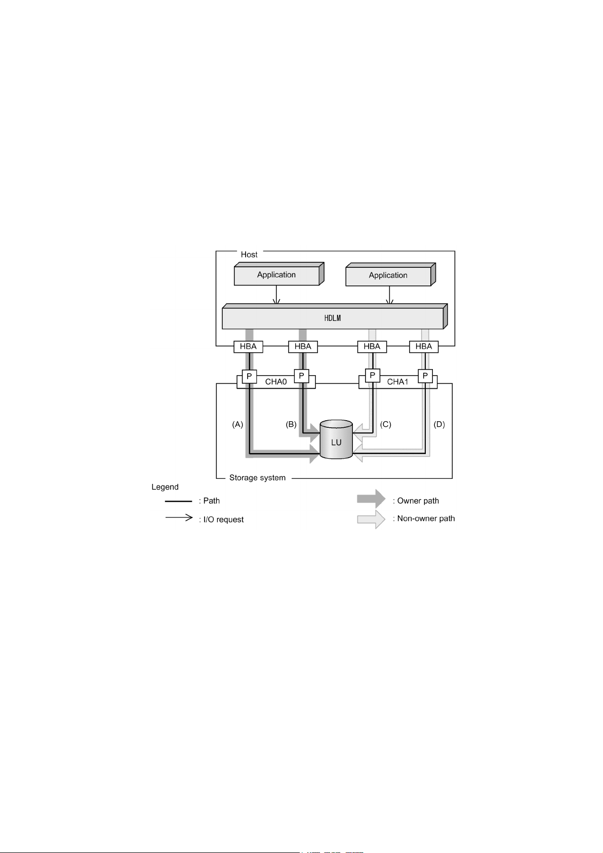
2. HDLM Functions
that uses a CHA other than the owner controller (a non-owner controller). Paths used
for load balancing are selected from owner paths first, then non-owner paths. To
prevent performance in the entire system from deteriorating, HDLM does not perform
load balancing between owner paths and non-owner paths. When some owner paths
cannot be used due to a problem such as a failure, load balancing is performed among
the remaining usable owner paths. When all owner paths cannot be used, load
balancing is performed among the non-owner paths.
For the example in Figure 2-9: Overview of Load Balancing, suppose that in the
owner controller of LU0 is CHA0. When the LU is accessed, the load is balanced
between the two paths A and B, which are both owner paths. When one of the paths
(A) cannot be used, then the LU is accessed from the only other owner path (B). When
both of the owner paths (A and B) cannot be used, the load is then balanced between
two other, non-owner paths (C and D).
Figure 2-9: Overview of Load Balancing
(2) When Using the Lightning 9900 Series, Lightning 9900V Series, Hitachi USP,
Universal Storage Platform V/VM, Virtual Storage Platform, Hitachi AMS2000
Series, or Hitachi SMS
All online paths are owner paths. Thus, for the example in Figure 2-8: Flow of I/O
22
Page 47

Data When the Load Balancing Function Is Used, the load is balanced among the four
paths A, B, C, and D. If one of the paths were to become unusable, the load would be
balanced among the three, remaining paths.
2.7.2 Load Balancing Algorithms
HDLM has the following six load balancing algorithms:
• The Round Robin algorithm
• The Extended Round Robin algorithm
• The Least I/Os algorithm
• The Extended Least I/Os algorithm
• The Least Blocks algorithm
• The Extended Least Blocks algorithm
The above algorithms are divided into two categories, which differ in their processing
method. The following describes both of these processing methods:
The Round Robin, Least I/Os, and Least Blocks algorithms
These algorithms select the path to use each time a certain number of I/Os are
issued. The path that is used is determined by the following:
2. HDLM Functions
• Round Robin
The paths are simply selected in order from among all the connected paths.
• Least I/Os
The path that has the least number of I/Os being processed is selected from
among all the connected paths.
• Least Blocks
The path that has the least number of I/O blocks being processed is selected
from among all the connected paths.
The Extended Round Robin, Extended Least I/Os, and Extended Least Blocks
algorithms
These algorithms determine which path to allocate based on whether the I/O to be
issued is sequential with the immediately preceding I/O.
If the I/O is sequential with the previous I/O, the path to which the previous I/O
was distributed will be used. However, if a specified number of I/Os has been
issued to a path, processing switches to the next path.
If the I/O is not sequential with the previous I/O, these algorithms select the path
to be used each time an I/O request is issued.
23
Page 48

2. HDLM Functions
Table 2-6: Features of the Load Balancing Algorithms describes the features of the
load balancing algorithms.
Algorithm type Algorithm features
• Extended Round Robin
The paths are simply selected in order from among all the connected paths.
• Extended Least I/Os
The path that has the least number of I/Os being processed is selected from
among all the connected paths.
• Extended Least Blocks
The path that has the least number of I/O blocks being processed is selected
from among all the connected paths.
Tabl e 2 -6 : Features of the Load Balancing Algorithms
• Round Robin
• Least I/Os
• Least Blocks
• Extended Round Robin
• Extended Least I/Os
• Extended Least Blocks
#
#
Some I/O operations managed by HDLM can be distributed across all, available
paths, and some cannot. Thus, you should be aware that even if you specify the
Round Robin algorithm, some of the I/O operations will never be issued
uniformly across all the given paths.
The default algorithm is the Extended Least I/Os algorithm, which is set when HDLM
is first installed. When an upgrade installation of HDLM is performed, the algorithm
that is currently being used is inherited.
Select the load balancing algorithm most suitable for the data access patterns of your
system environment. However, if there are no recognizable data access patterns, we
recommend using the default algorithm, the Extended Least I/Os algorithm.
You can specify the load balancing function by the
operation. For details on the
Environment).
These types of algorithms are most effective when a lot of discontinuous,
non-sequential I/Os are issued.
If the I/O data is from something like a read request and is generally sequential
with the previous I/Os, an improvement in reading speed can be expected due
to the storage system cache functionality. These types of algorithms are most
effective when a lot of continuous, sequential I/Os are issued.
dlnkmgr command's set
set operation, see 6.6 set (Sets Up the Operating
24
Page 49

2. HDLM Functions
2.8 Performing Failovers and Failbacks Using Path Switching
When the system contains multiple paths to an LU and an error occurs on the path that
is currently being used, HDLM can switch to another functional path, so that the
system can continue operating. This is called a failover.
If a path in which an error has occurred recovers from the error, HDLM can then switch
back to that path. This is called a failback.
Two types of failovers and failbacks are available:
• Automatic failovers and failbacks
• Manual failovers and failbacks
Failovers and failbacks switch which path is being used and also change the statuses
of the paths. A path status is either online or offline. An online status means that the
path can receive I/Os. On the other hand, an offline status means that the path cannot
receive I/Os. A path will go into the offline status for the following reasons:
• An error occurred on the path.
• A user executed the HDLM command's
For details on the
offline operation, see 6.4 offline (Places Paths Offline).
For details on path statuses and the transitions of those statuses, see 2.8.3 Path Status
Transition.
2.8.1 Automatic Path Switching
The following describes the automatic failover and failback functions, which
automatically switch a path.
(1) Automatic Failovers
If you detect an error on the path that is currently being used, you can continue to use
the system by having the status of that path automatically changed to offline, and then
automatically have the system switch over to another online path. This functionality is
called automatic failover. Automatic failovers can be used for the following levels of
errors:
Critical
A fatal error that might stop the system.
Error
A high-risk error, which can be avoided by performing a failover or some other
countermeasure.
offline operation.
25
Page 50

2. HDLM Functions
For details on error levels, see 2.11.2 Filtering of Error Information.
When the Thunder 9500V series, or Hitachi AMS/WMS series is being used, HDLM
will select the path to be used next from among the various paths that access the same
LU, starting with owner paths, and then non-owner paths. For example, in
Figure 2-10: Path Switching, the owner controller of an LU is CHA0, and access to
the LU is made via only one path (A). After that access path (A) is placed offline, the
first choice for the switching destination is the other path connected to CHA0 (B). If
an error also occurs on that path (B), then the next possibility for a path comes from
one of the two paths (C or D) connected to CHA1.
When the Lightning 9900 series, Lightning 9900V series, Hitachi USP, Universal
Storage Platform V/VM, Virtual Storage Platform, Hitachi AMS2000 series, or
Hitachi SMS is being used, all the paths are owner paths. This means that all the paths
that are accessing the same LU are possible switching destinations. For example, in
Figure 2-10: Path Switching, the LU is accessed using only the one path (A).
However, after that path is placed offline, the switching destination can come from any
of the other three paths (B, C, or D).
26
Page 51

Figure 2-10: Path Switching
2. HDLM Functions
(2) Automatic Failbacks
When a path recovers from an error, HDLM can automatically place the recovered
path back online. This function is called the automatic failback function. In order to
use the automatic failback function, HDLM must already be monitoring error recovery
on a regular basis.
When using the Thunder 9500V series, or Hitachi AMS/WMS series, HDLM will
select the next path to be used first from among the online owner paths, and then from
the online non-owner paths. As a result, if an owner path recovers from an error, and
then HDLM automatically places the recovered path online while a non-owner path is
in use, the path will be automatically switched over from the non-owner path to the
owner path that just recovered from the error.
When the Lightning 9900 series, Lightning 9900V series, Hitachi USP, Universal
27
Page 52

2. HDLM Functions
Storage Platform V/VM, Virtual Storage Platform, Hitachi AMS2000 series, or
Hitachi SMS is being used, all the paths are owner paths. As a result, if the path that
was previously used recovers from an error, and then HDLM automatically places the
recovered path online, the path that is currently being used will continue to be used (as
opposed to switching over to the path that was just recovered).
When intermittent errors
function, the path status might frequently alternate between the online and offline
statuses. In such a case, because the performance of I/Os will most likely decrease, if
there are particular paths in which intermittent errors might be occurring, we
recommend that you set up intermittent error monitoring so you can detect these paths,
and then remove them from those subject to automatic failbacks.
#
occur on paths and you are using the automatic failback
You can specify the automatic failback function or intermittent error by the
command's
set operation. For details on the set operation, see 6.6 set (Sets Up the
Operating Environment).
#
An intermittent error means an error that occurs irregularly because of some
reason such as a loose cable connection.
2.8.2 Manual Path Switching
You can switch the status of a path by manually placing the path online or offline.
Manually switching a path is useful, for example, when system maintenance needs to
be done.
You can manually place a path online or offline by doing the following:
• Execute the
For details on the
details on the
However, if there is only one online path for a particular LU, that path cannot be
manually switched offline. Also, a path with an error that has not been recovered from
yet cannot be switched online.
HDLM uses the same algorithms to select the path that will be used next, regardless of
whether automatic or manual path switching is used.
When using the Thunder 9500V series, or Hitachi AMS/WMS series, HDLM will
select the next path to be used first from among the online owner paths, and then from
the online non-owner paths. When the Lightning 9900 series, Lightning 9900V series,
Hitachi USP, Universal Storage Platform V/VM, Virtual Storage Platform, Hitachi
AMS2000 series, or Hitachi SMS is being used, all the paths that access the same LU
as the path that is currently being used are candidates for the switching destination
path.
dlnkmgr command's online or offline operation.
online operation, see 6.5 online (Places Paths Online). For
offline operation, see 6.4 offline (Places Paths Offline).
dlnkmgr
28
Page 53

Executing the online operation places the offline path online. For details on the
online operation, see 6.5 online (Places Paths Online). After a path status is
changed to online, the path can be selected as a useable path by HDLM in the same
manner as automatic path switching. When using the Thunder 9500V series, or Hitachi
AMS/WMS series, HDLM selects the path to use from online owner paths, and then
from online non-owner paths. When the Lightning 9900 series, Lightning 9900V
series, Hitachi USP, Universal Storage Platform V/VM, Virtual Storage Platform,
Hitachi AMS2000 series, or Hitachi SMS is being used, since all the paths are owner
paths, the path to use is not switched even if you change the path status to online by
using the
online operation.
2.8.3 Path Status Transition
Each of the online and offline statuses described in 2.8 Performing Failovers and
Failbacks Using Path Switching is further subdivided into two statuses. The following
explains the two online path statuses and the two offline statuses.
(1) The Online Path Status
The online path statuses are as follows:
•
Online
I/Os can be issued normally.
•
Online(E)
2. HDLM Functions
An error has occurred on the path, but none of the other paths that access the same
LU are in the
Online status.
If none of the paths accessing a particular LU are in the
paths is changed to the
accessed through at least one path.
The (E) means error, which indicates that an error has occurred on the path from
some previous operation.
(2) The Offline Path Status
The offline path statuses are as follows:
•
Offline(C)
The status in which I/O cannot be issued because the offline operation was
executed. For details on the
Offline).
The (C) indicates the command attribute, which indicates that the path was placed
offline by using the command.
Offline(E)
•
Online status, one of the
Online(E) status. This ensures that the LU can be
offline operation, see 6.4 offline (Places Paths
29
Page 54

2. HDLM Functions
The status indicating that an I/O could not be issued on a given path, because an
error occurred on the path.
The (E) means error.
(3) Status Transitions of a Path
Figure 2-11: Path Status Transitions shows the status transitions of a path.
Figure 2-11: Path Status Transitions
30
Legend:
Online operation: Online operation performed by executing the
command's
online operation.
Offline operation: Offline operation performed by executing the
command's
offline operation.
dlnkmgr
dlnkmgr
#1
When the following conditions are satisfied, a path that has been determined to
have an intermittent error also becomes subject to automatic failback:
Page 55

2. HDLM Functions
• All the paths connected to an LU are Online(E), Offline(E), or
Offline(C).
• All the paths connected to an LU have been determined to have an
intermittent error.
• The processing of continuous I/O operations issued to an LU is successful.
#2
When an Online or Offline(E) path exists among the paths that access the same
LU.
If there is only one available online path for an LU, it cannot be placed offline by
executing the
at least one path. For details on the
offline operation. This ensures that the LU can always be accessed by
offline operation, see 6.4 offline (Places Paths
Offline).
If an error occurs in the only available online path for an LU, the status of the path will
change to
Online(E).
If you are using the automatic failback function, after the path has recovered from the
error, HDLM will automatically place the path online.
When you are using intermittent error monitoring, the path in which the intermittent
error occurred is not automatically placed online when the path recovers from the error.
In such a case, place the path online manually.
Note:
If there is a path failure immediately after a path is taken offline by using either
the an HDLM command, the status might change from
Offline(E). If an offline operation was just performed, wait about 1 minutes,
Offline(C) to
check the path status by using an HDLM command, and then make sure that the
status has changed to
Offline(C). If it is still Offline(E), retry the offline
operation.
31
Page 56

2. HDLM Functions
2.9 Monitoring Intermittent Errors (Functionality When Automatic
Failback Is Used)
An intermittent error refers to an error that occurs irregularly because of something
like a loose cable. In such a case, I/O performance might decrease while an automatic
failback is being performed to repair an intermittent error. This is because the
automatic failback operation is being performed repeatedly (because the intermittent
error keeps occurring). To prevent this from happening, HDLM can automatically
remove the path where an intermittent error is occurring from the paths that are subject
to automatic failbacks. This process is called intermittent error monitoring.
We recommend that you use intermittent error monitoring along with the automatic
failback function.
A path in which an error occurs a specified number of times within a specified interval
is determined to have an intermittent error. The path where an intermittent error occurs
has an error status until the user chooses to place the path back online. Failbacks are
not performed for such paths. This status is referred to as the not subject to auto
failback status.
2.9.1 Checking Intermittent Errors
You can check the paths in which intermittent errors have occurred by viewing the
execution results of the HDLM command's
view operation.
For details on the
view operation, see 6.7 view (Displays Information).
2.9.2 Setting Up Intermittent Error Monitoring
When you enable the intermittent error monitoring function, specify the following
monitoring conditions: the error monitoring interval, and the number of times that the
error needs to occur. If an error occurs on a particular path the specified number of
times within the specified error-monitoring interval, then an intermittent error will
occur on the path. For example, if you specify 30 for the error monitoring interval and
3 for the number of times that the error needs to occur, the path is determined to have
an intermittent error if an error occurs 3 or more times in 30 minutes.
You can set up intermittent error monitoring by executing the
set operation.
Intermittent error monitoring can be used only when automatic failback has already
been enabled. The values that can be specified for intermittent error monitoring depend
on the values specified for automatic failbacks. For details on how to specify the
settings, see 6.6 set (Sets Up the Operating Environment).
32
dlnkmgr command's
Page 57

2.9.3 Intermittent Error Monitoring Actions
Intermittent error monitoring is performed on each path, and it automatically starts as
soon as a path is recovered from an error by using the automatic failback function.
This subsection describes the following intermittent error monitoring actions:
• When an intermittent error occurs
• When an intermittent error does not occur
• When the conditions for an intermittent error to occur are changed during error
monitoring
(1) When an Intermittent Error Occurs
When an error occurs on a path a specified number of times within a specified interval,
the error monitoring will finish and the path is determined to have an intermittent error,
upon which the path is removed from those subject to automatic failbacks. The path
that is removed will remain in the error status until the
However, if the path satisfies certain conditions (see Figure 2-11: Path Status
Transitions), it will be subject to automatic failbacks and change to the
Figure 2-12: Action What Will Happen When an Intermittent Error Occurs on a Path
shows what will happen when an intermittent error occurs. For this example, the path
is determined to have an intermittent error when the error occurs 3 or more times
within 30 minutes. The events that occur are described by using the time arrows.
2. HDLM Functions
online operation is performed.
Online status.
Figure 2-12: Action What Will Happen When an Intermittent Error Occurs on a
Path
33
Page 58
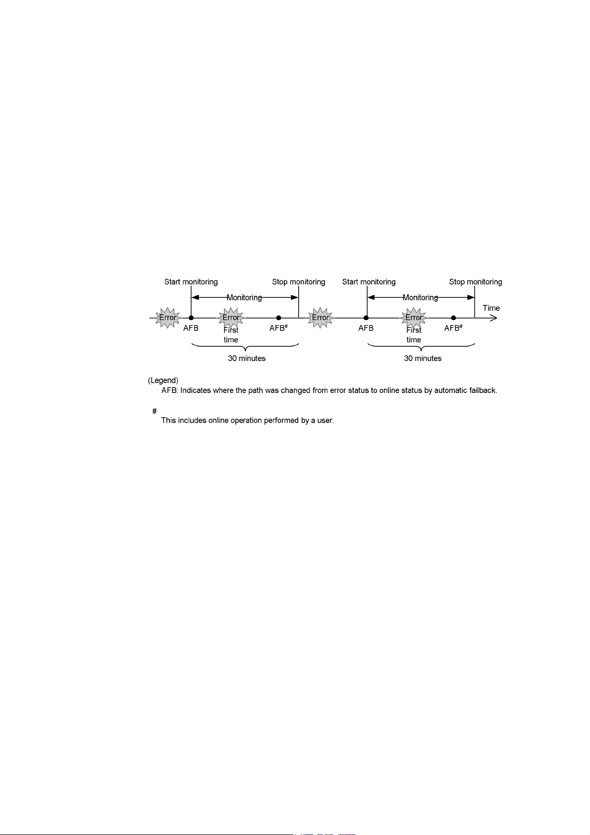
2. HDLM Functions
(2) When an Intermittent Error Does Not Occur
If an error does not occur on a path a specified number of times within a specified
interval, an intermittent error will not occur. In such a case, the error monitoring will
finish when the specified error-monitoring interval finishes, upon which the number of
errors is reset to 0. If an error occurs on the path again at a later time, error monitoring
will resume when the path is recovered from the error via an automatic failback.
If it takes a long time for an error to occur, an intermittent error can be more easily
detected by increasing the error-monitoring interval or by decreasing the number of
times that the error needs to occur.
Figure 2-13: What Will Happen When an Intermittent Error Does Not Occur on a
Path shows what will happen when an intermittent error does not occur. For this
example, the path is determined to have an intermittent error if the error occurs three
or more times in 30 minutes. The events that occur are described by using the time
arrows.
Figure 2-13: What Will Happen When an Intermittent Error Does Not Occur on
a Path
34
As shown in Figure 2-13: What Will Happen When an Intermittent Error Does Not
Occur on a Path, normally, the count for the number of times that an error occurs is
started after the path is first recovered from an error by using the automatic failback
function. However, if all the paths connected to the LU are in the
Online(E), or Offline(C) status (which is due to the disconnection of the paths or
Offline(E),
some other reason), the paths will not be recovered and put back online by using the
automatic failback function. If I/O operations are continuously being issued to such an
LU, the count for the number of times that the error occurs might be started even
though the path will not be placed online. If the number of times that the error occurs
reaches the specified value, the path is determined to have an intermittent error. In such
a case, remove the cause of the error, and then manually place the path online.
Page 59

2. HDLM Functions
(3) When the Conditions for an Intermittent Error Are Changed During Error
Monitoring
When the conditions for an intermittent error are changed during error monitoring, the
number of errors and the amount of time that has passed since the error monitoring
started are both reset to 0. As such, the error monitoring will not finish, and it will start
over by using the new conditions.
If the conditions are changed while error monitoring is not being performed, error
monitoring will start up again and use the updated conditions after any given path is
recovered from an error by performing an automatic failback.
Figure 2-14: What Will Happen When Conditions Are Changed During Error
Monitoring shows what will happen when the conditions for an intermittent error are
changed during error monitoring. For this example, the conditions have been changed
from 3 or more errors in 30 minutes, to 3 or more errors in 40 minutes. The events that
occur are described by using the time arrows.
Figure 2-14: What Will Happen When Conditions Are Changed During Error
Monitoring
2.9.4 When a User Changes the Intermittent Error Information
The following might be reset when a user changes any of the values set for the
intermittent error or the path status: the number of errors that have already been
counted during error monitoring, the amount of time that has passed since error
monitoring has started, and the information about whether an intermittent error has
occurred. Table 2-7: When Effects of a User Changing the Intermittent Error
Information lists whether the above items are reset.
If you want to check whether intermittent error monitoring is being used for a path,
35
Page 60

2. HDLM Functions
check the IEP item displayed when the dlnkmgr command's view -path operation
is executed with the
Intermittent Error Path item, then intermittent error monitoring is being performed.
-iem parameter specified. If 0 or greater is displayed in the
Tabl e 2 -7 : When Effects of a User Changing the Intermittent Error Information
User operation Number of errors
Changing the intermittent
Turning
off Reset
error monitoring settings
Changing the conditions for an
intermittent error while intermittent
error monitoring is being performed
Turning intermittent error
monitoring on by executing the set
operation, (but not changing the
conditions) while intermittent error
monitoring is being performed
Changing the intermittent error
monitoring conditions while
intermittent error monitoring is not
being performed
Changing the automatic
Turning
off Reset Reset
failback settings
Changing the path status Taking the path
Placing the path Online while
intermittent error monitoring is not
being performed
and time passed
about paths not
since error
monitoring
started
Reset
Information
#2
Reset
(Not applicable) (Not
Inherited
Inherited
counted.)
Offline(C) Reset Reset
(Not applicable) (Not
Reset
counted.)
subject to
automatic
failback
#1
Placing the path
intermittent error monitoring is
being performed
Online while
Inherited (Not applicable)
If a path has been
removed from the
paths subject to
automatic
monitoring, that
path is no longer
monitored.
Restarting the HDLM manager
Reset
#3
Inherited
Restarting the host Reset Reset
#1
36
Page 61

2. HDLM Functions
When you turn the intermittent error monitoring function off, information about
paths not subject to automatic failback will be reset. If you do not want to reset
the information about paths not subject to automatic failback when you turn the
intermittent error monitoring function off, change the target paths to
Offline(C).
#2
The number of errors and the time passed since error monitoring had started are
both reset to
0, and then monitoring restarts from the time the setting change is
made in accordance with the changed monitoring conditions.
#3
The number of errors and the time passed since error monitoring had started are
both reset to
0, and then monitoring restarts from the time the HDLM manager
starts.
37
Page 62

2. HDLM Functions
2.10 Detecting Errors by Using Path Health Checking
HDLM can check the status of paths for which I/O operations are not being performed
at regular intervals. This function is called path health checking.
Without path health checking, an error cannot be detected unless an I/O operation is
performed, because the system only checks the status of a path when an I/O operation
is performed. With path health checking, however, the system can check the status of
all online paths at regular intervals regardless of whether I/Os operations are being
performed. If an error is detected in a path, the path health checking function switches
the status of that path to
command's
view operation to check the path error.
For example, in a normal state, I/O operations are not performed on the paths coming
from the standby host in the cluster configuration or on non-owner paths (that is, some
of the paths that access a Thunder 9500V series and Hitachi AMS/WMS series storage
system). Because of this, for the standby host or for a host connected to non-owner
paths, we recommend that you use path health checking to detect errors. This enables
the system to use the most up-to-date path-status information when selecting the next
path to use.
Offline(E) or Online(E). You can use the dlnkmgr
You can configure path health checking by executing the
operation. For details on the
set operation, see 6.6 set (Sets Up the Operating
Environment).
dlnkmgr command's set
38
Page 63

2.11 Error Management
HDLM collects information for troubleshooting into log files. HDLM can also filter
error information according to the error level when collecting the information.
Figure 2-15: Flow of Data When Collecting Error Information shows the flow of
data when collecting error information.
2. HDLM Functions
39
Page 64

2. HDLM Functions
Figure 2-15: Flow of Data When Collecting Error Information
40
Logs might be collected in layers below HDLM, such as for the SCSI driver. For more
details, see the Linux documentation.
Page 65

2.11.1 Types of Collected Logs
HDLM collects information on the detected error and trace information in the
process-specific-trace information file, trace file, error logs, log for the dlmcfgmgr
utility for managing the HDLM configuration and syslog. You can use the error
information to examine the status of an error and analyze the cause of the error.
Table 2-8: Types of Error Information describes the types of error information.
Tabl e 2 -8 : Types of Error Information
2. HDLM Functions
Log
Description Output destination
name
Process-sp
Operation logs for the HDLM command are collected. The default file path is
ecific-trac
e
informatio
n file
Trace file Trace information on the HDLM manager is collected at the
level specified by the user. If an error occurs, you might need
to change the settings to collect trace information.
Error log Error information is collected for the user-defined level. By
default, HDLM collects all error information.
HDLM-co
Logs are collected when the
dlmcfgmgr utility is executed. The following is the log file name.
nfiguratio
n
definition
utility
dlmcfgm
(
) log
gr
DynamicLinkManager/log/
dlnkmgr[1-2].log
/var/opt/
.
The following is the trace file
name:
/var/opt/
DynamicLinkManager/log/
hdlmtr[1-64].log
HDLM Manager logs:
/var/opt/
DynamicLinkManager/log/
dlmmgr[1-16].log
Hitachi Command Suite Common
Agent Component logs:
/var/opt/
DynamicLinkManager/log/
dlmwebagent[1-
N].log
The value N depends on the setting
in the file
dlmwebagent.properties.
/var/opt/
•
DynamicLinkManager/log/
dlmcfgmgr[1-2].log
• /var/opt/
DynamicLinkManager/log/
dlminquiry.log
Syslog The HDLM messages on or above the level set by the user
with syslogd settings file are collected.
#
We recommend that you configure the system so that
information at the Information level and higher is output.
Syslogs can be checked using a text editor.
The default file path is /var/log/
messages.
The syslog file path is specified in
the syslogd settings file. For
details, see the Linux
documentation.
41
Page 66

2. HDLM Functions
#
When you want to configure the system so that HDLM messages are output to
syslog, specify
user for the facility in the syslog settings file. The following
shows an example where the system function name is
info level or higher are output to the /tmp/syslog.user.log file:
user.info /tmp/syslog.user.log
For details on error levels, see 2.11.2 Filtering of Error Information.
2.11.2 Filtering of Error Information
Errors detected by HDLM are classified into various error levels. Table 2-9: Error
Levels lists the error levels, in the order of most to least severe.
Tabl e 2 -9 : Error Levels
user, and messages at the
Error
level
Critical Fatal errors that might stop the system.
Error Errors that adversely affect the system. This type of error can be avoided by performing a failover
or other countermeasures.
Warning Errors that enable the system to continue but, if left, might cause the system to improperly operate.
InformationInformation that simply indicates the operating history when the system is operating normally.
Meaning
Error information is filtered by error level, and then collected.
The error level is equivalent to the level of the messages output by HDLM. For details
on the level of the message, see 8.1.1 Format and Meaning of Message IDs.
In syslog, the HDLM messages on or above the level set by the user configured in
syslogd settings file are collected. It is recommended that you set the information to be
output at the Information level or higher.
Note that all the facilities when HDLM outputs messages in syslog are user.
The error information in error logs and trace files are collected based on a user-defined
collection level. The collection levels are as follows:
Collection levels for error logs
• Collects no error information.
42
• Collects error information from the Error level and higher.
• Collects error information from the Warning level and higher.
Page 67

2. HDLM Functions
• Collects error information from the Information level and higher.
• Collects error information from the Information level and higher (including
maintenance information).
Collection levels for log information in trace files:
• Outputs no trace information
• Outputs error information only
• Outputs trace information on program operation summaries
• Outputs trace information on program operation details
• Outputs all trace information
For details on how to set the collection level, see 3.18.2 Setting Up the HDLM
Functions.
2.11.3 Collecting Error Information Using the Utility for Collecting
HDLM Error Information (DLMgetras)
HDLM has a utility for collecting HDLM error information (DLMgetras).
By executing this utility, you can simultaneously collect all the information required
for analyzing errors: information such as error logs, process-specific-trace information
files, trace files, definition files, core files, and libraries. You can use the collected
information when you contact your HDLM vendor or maintenance company (if there
is a maintenance contract for HDLM).
For details on the
Error Information.
DLMgetras utility, see 7.2 DLMgetras Utility for Collecting HDLM
2.11.4 Utility for Collecting HDLM Installation Error Information
(installgetras)
HDLM has a utility for collecting HDLM installation error information
(
installgetras).
By executing this utility, you can collect the logs required for analyzing errors that
occurred during installation. You can use the collected information when you contact
your HDLM vendor or maintenance company.
For details on the
HDLM Installation Error Information.
installgetras utility, see 7.9 installgetras Utility for Collecting
43
Page 68

2. HDLM Functions
2.12 Collecting Audit Log Data
HDLM and other Hitachi storage-related products provide an audit log function so that
compliance with regulations, security evaluation standards, and industry-specific
standards can be shown to auditors and evaluators. The following table describes the
categories of audit log data that Hitachi storage-related products can collect.
Table 2-10: Categories of Audit Log Data that Can Be Collected
Category Explanation
StartStop An event indicating the startup or termination of hardware or software,
including:
• OS startup and termination
• Startup and termination of hardware components (including
micro-program)
• Startup and termination of software running on storage systems, software
running on SVPs (service processors), and Hitachi Command Suite
products
Failure An abnormal hardware or software event, including:
• Hardware errors
• Software errors (such as memory errors)
LinkStatus An event indicating the linkage status between devices:
• Link up or link down
ExternalService An event indicating the result of communication between a Hitachi
Authentication An event indicating that a connection or authentication attempt made by a
AccessControl An event indicating that a resource access attempt made by a device,
44
storage-related product and an external service, including:
• Communication with a RADIUS server, LDAP server, NTP server, or
DNS server,
• Communication with the management server (SNMP)
device, administrator, or end-user has succeeded or failed, including:
• FC login
• Device authentication (FC-SP authentication, iSCSI login authentication,
or SSL server/client authentication)
• Administrator or end-user authentication
administrator, or end-user has succeeded or failed, including:
• Device access control
• Administrator or end-user access control
Page 69

2. HDLM Functions
Category Explanation
ContentAccess An event indicating that an attempt to access critical data has succeeded or
failed, including:
• Access to a critical file on a NAS or content access when HTTP is
supported
• Access to the audit log file
ConfigurationAccess An event indicating that a permitted operation performed by the administrator
Maintenance An event indicating that a maintenance operation has terminated normally or
AnomalyEvent An event indicating an abnormal state such as exceeding a threshold,
has terminated normally or failed, including:
• Viewing or updating configuration information
• Updating account settings, such as adding and deleting accounts
• Setting up security
• Viewing or updating audit log settings
failed, including:
• Adding or removing hardware components
• Adding or removing software components
including:
• Exceeding a network traffic threshold
• Exceeding a CPU load threshold
• Reporting that the temporary audit log data saved internally is close to its
maximum size limit or that the audit log files have wrapped back around
to the beginning
An event indicating an occurrence of abnormal communication, including:
• A SYN flood attack or protocol violation for a normally used port
• Access to an unused port (such as port scanning)
The categories of audit log data that can be collected differ depending on the product.
The following sections explain only the categories of audit log data that can be
collected by HDLM. For the categories of audit log data that can be collected by a
product other than HDLM, see the corresponding product manual.
2.12.1 Categories and Audit Events that HDLM Can Output to the
Audit Log
The following table lists and explains the categories and audit events that HDLM can
output to the audit log. The severity is also indicated for each audit event.
45
Page 70

2. HDLM Functions
Table 2-11: Categories and Audit Events that Can Be Output to the Audit Log
Category Explanation Audit event Severity#1Message
StartStop Startup and
termination of the
software
Authentication Administrator or
end-user
authentication
Startup of the HDLM
manager was successful.
Startup of the HDLM
manager failed.
The HDLM manager
stopped.
Startup of the
DLMgetras
utility
Termination of the
DLMgetras utility
#2
Processing of the
dlmstart utility was
successful.
Processing of the
dlmstart utility failed.
Permission has not been
granted to execute the
HDLM command.
ID
6 KAPL154
01-I
3 KAPL154
02-E
6 KAPL154
03-I
6 KAPL150
60-I
6 KAPL150
61-I
6 KAPL150
62-I
3 KAPL150
63-E
4 KAPL151
11-W
ConfigurationAccess Viewing or updating
configuration
information
46
Permission has not been
granted to execute HDLM
utilities.
Permission has not been
granted to start or stop the
HDLM manager.
Initialization of path
statistics was successful.
Initialization of path
statistics failed.
An attempt to place a path
online or offline was
successful.
An attempt to place a path
online or offline failed.
4 KAPL150
10-W
4 KAPL154
04-W
6 KAPL151
01-I
3 KAPL151
02-E
6 KAPL151
03-I
4 KAPL151
04-W
Page 71

2. HDLM Functions
Category Explanation Audit event Severity
#1
Setup of the operating
6KAPL151
environment was
successful.
Setup of the operating
3KAPL151
environment failed.
An attempt to display
6KAPL151
program information was
successful.
An attempt to display
3KAPL151
program information failed.
An attempt to display
6KAPL151
HDLM management-target
information was successful.
An attempt to display
3KAPL151
HDLM management-target
information failed.
Processing of the
dlmpr -k
6KAPL150
command was successful.
Processing of the
dlmpr -k
3KAPL150
command failed.
Message
ID
05-I
06-E
07-I
08-E
09-I
10-E
01-I
02-E
Processing of the
dlmpr -c
command was successful.
Processing of the
dlmpr -c
command failed.
Processing of the
dlmcfgmgr -r command
was successful.
Processing of the
dlmcfgmgr -r command
failed.
Processing of the
dlmcfgmgr -o command
was successful.
Processing of the
dlmcfgmgr -o command
failed.
6KAPL150
64-I
3KAPL150
65-E
6KAPL150
40-I
3KAPL150
41-E
6KAPL150
42-I
3KAPL150
43-E
47
Page 72

2. HDLM Functions
Category Explanation Audit event Severity
#1
Processing of the
dlmcfgmgr -i command
6 KAPL150
was successful.
Processing of the
dlmcfgmgr -i command
3 KAPL150
failed.
Processing of the
dlmcfgmgr -v command
6 KAPL150
was successful.
Processing of the
dlmcfgmgr -v command
3 KAPL150
failed.
Processing of the
dlmcfgmgr -u command
6 KAPL150
was successful.
Processing of the
dlmcfgmgr -u command
3 KAPL150
failed.
Processing of the
dlmmkinitrd command
6 KAPL150
was successful.
Message
ID
44-I
45-E
46-I
47-E
48-I
49-E
50-I
48
Processing of the
dlmmkinitrd command
failed.
Processing of the
dlmsetopt -r command
was successful.
Processing of the
dlmsetopt -r command
failed.
Processing of the
dlmsetopt -inqt
command was successful.
Processing of the
dlmsetopt -inqt
command failed.
3 KAPL150
51-E
6 KAPL150
52-I
3 KAPL150
53-E
6 KAPL150
54-I
3 KAPL150
55-E
Page 73

2. HDLM Functions
Category Explanation Audit event Severity
Processing of the
dlmsetopt -inqr
command was successful.
Processing of the
dlmsetopt -inqr
command failed.
Processing of the
dlmupdatesysinit
command was successful.
Processing of the
dlmupdatesysinit
command failed.
#1
6KAPL150
3KAPL150
6KAPL150
3KAPL150
#1
The severity levels are as follows:
3: Error, 4: Warning, 6: Informational
#2
If you use Ctrl + C to cancel the
information, audit log data indicating that the
DLMgetras utility for collecting HDLM error
DLMgetras utility has terminated
will not be output.
Message
ID
56-I
57-E
58-I
59-E
2.12.2 Requirements for Outputting Audit Log Data
HDLM can output audit log data when all of the following conditions are satisfied:
• The
• The output of audit log data has been enabled by using the HDLM command's
However, audit log data might still be output regardless of the above conditions if, for
example, an HDLM utility is executed from external media.
#:
Notes:
syslog daemon is active.
set operation.
The following audit log data is output:
• Categories:
StartStop, Authentication, and ConfigurationAccess
• Severity: 6 (Critical, Error, Warning, or Informational)
• Destination: syslog (facility value:
user)
#
49
Page 74

2. HDLM Functions
• You might need to perform operations such as changing the log size and
backing up and saving collected log data, because the amount of audit log
data might be quite large.
• If the severity specified by the HDLM command's
from the severity specified by the configuration file
the higher severity level is used for outputting audit log data.
2.12.3 Destination and Filtering of Audit Log Data
Audit log data is output to syslog. Because HDLM messages other than audit log data
are also output to
is used exclusively for audit log data.
For example, to change the output destination of audit log data to
audlog
, specify the following two settings:
• Specify the following setting in the
local0.info /usr/local/audlog
• Use the HDLM command's set operation to specify local0 for the audit log
facility:
You can also filter the audit log output by specifying a severity level and type for the
HDLM command's
Filtering by severity:
The following table lists the severity levels that can be specified.
Table 2-12: Severity Levels That Can Be Specified
syslog, we recommend that you specify the output destination that
/etc/syslog.conf file:
set operation.
set operation differs
/etc/syslog.conf,
/usr/local/
Severity Audit log data to output Correspondence with syslog
0None Emergency
1Alert
2 Critical Critical
3 Critical and Error Error
4 Critical, Error, and Warning Warning
5Notice
6 Critical, Error, Warning, and Informational Informational
7Debug
50
severity levels
Page 75

Filtering by category:
The following categories can be specified:
•
StartStop
• Authentication
• ConfigurationAccess
• All of the above
For details on how to specify audit log settings, see 3.18.2 Setting Up the HDLM
Functions.
2.12.4 Audit Log Data Formats
The following describes the format of audit log data:
Format of audit log data output to syslog:
• priority
• date-and-time
• host-name
• program-name
2. HDLM Functions
• [process-ID]
• message-section
The following shows the format of message-section and explains its contents.
The format of message-section:
common-identifier
sage-ID
,date-and-time,entity-affected,location-affected,audit-event-type,aud
it-event-result
mation
,location-information,location-identification-information,FQDN,redu
,common-specification-revision-number,serial-number,mes
,subject-ID-for-audit-event-result,hardware-identification-infor
ndancy-identification-information
rt-number-sending-request
est
,common-operation-ID,log-type-information,application-identification-info
rmation
,reserved-area,message-text
Up to 950 bytes of text can be displayed for each message-section.
Tabl e 2 -1 3: Items Output in the Message Section
#
Item
Common identifier Fixed to
,agent-information,host-sending-request,po
,host-receiving-request,port-number-receiving-requ
Explanation
CELFSS
51
Page 76

2. HDLM Functions
#
Item
Common specification
Fixed to
1.1
Explanation
revision number
Serial number Serial number of the audit log message
Message ID Message ID in KAPL15nnn-l format
Date and time The date and time when the message was output. This item is output in the
following format:
-mm-ddThh:mm:ss.s time-zone
yyyy
Entity affected Component or process name
Location affected Host name
Audit event type Event type
Audit event result Event result
Subject ID for audit event
Depending on the event, an account ID, process ID, or IP address is output.
result
Hardware identification
Hardware model name or serial number
information
Location information Hardware component identification information
Location identification
Location identification information
information
FQDN Fully qualified domain name
Redundancy identification
Redundancy identification information
information
Agent information Agent information
Host sending request Name of the host sending a request
Port number sending request Number of the port sending a request
Host receiving request Name of the host receiving a request
Port number receiving
Number of the port receiving a request
request
Common operation ID Operation serial number in the program
Log type information Fixed to
Application identification
Program identification information
BasicLog
information
52
Page 77

2. HDLM Functions
#
Item
Reserved area This field is reserved. No data is output here.
Message text Data related to the audit event is output.
Explanation
#: The output of this item depends on the audit event.
Example of the message section for the audit event An attempt to display HDLM
management-target information was successful:
CELFSS,1.1,0,KAPL15109-I,2008-04-09T10:18:40.6+09:00,HDLMCo
mmand,hostname=moon,ConfigurationAccess,Success,uid=root,,,
,,,,,,,,,,,,"Information about HDLM-management targets was
successfully displayed. Command Line = /opt/
DynamicLinkManager/bin/dlnkmgr view -path "
53
Page 78

2. HDLM Functions
2.13 Integrated HDLM management using Global Link Manager
By using Global Link Manager, you can perform integrated path management on
systems running multiple instances of HDLM.
For large-scale system configurations using many hosts running HDLM, the
operational load for managing paths on individual hosts increases with the size of the
configuration. By linking HDLM and Global Link Manager, you can centrally manage
path information for multiple instances of HDLM and reduce operational load. In
addition, you can switch the operational status of paths to perform system-wide load
balancing, and centrally manage the system by collecting HDLM failure information
in Global Link Manager.
Global Link Manager collects and manages information about paths from instances of
HDLM installed on multiple hosts. Even if multiple users manage these hosts, they can
control and view this centralized information from client computers.
For an example of a system configuration using HDLM and Global Link Manager, see
Figure 2-16: Example System Configuration Using HDLM and Global Link
Manager.
54
Page 79

2. HDLM Functions
Figure 2-16: Example System Configuration Using HDLM and Global Link
Manager
55
Page 80

2. HDLM Functions
2.14 Cluster Support
HDLM can also be used in cluster configurations.
For details about the cluster software supported by HDLM, see (1) Cluster Software
Supported by HDLM in 3.1.3 Related Products When Using Red Hat Enterprise Linux
AS4/ES4, (1) Cluster Software Supported by HDLM (If an FC-SAN Is Used) in
3.1.4 Related Products When Using Red Hat Enterprise Linux 5, (1) Cluster Software
Supported by HDLM (If an FC-SAN Is Used) in 3.1.5 Related Products When Using
Red Hat Enterprise Linux 6, (1) Cluster Software Supported by HDLM in
3.1.6 Related Products When Using SUSE LINUX Enterprise Server 9, (1) Cluster
Software Supported by HDLM in 3.1.7 Related Products When Using SUSE LINUX
Enterprise Server 10, or (1) Cluster Software Supported by HDLM in 3.1.10 Related
Products When Using Oracle Enterprise Linux 5.
HDLM uses a path of the active host to access an LU.
The details of host switching depend on the application.
56
Page 81

Chapter
3. Creating an HDLM Environment
This chapter explains the procedure for setting up an HDLM environment and the
procedure for canceling the environment settings.
Make sure that HDLM installation and function setup has been performed. Set up
volume groups and cluster software according to the environment you are using.
3.1 HDLM System Requirements
3.2 Flow for Creating an HDLM Environment
3.3 HDLM Installation Types
3.4 Knowledge Required Before You Install HDLM
3.5 Notes on Creating an HDLM Environment
3.6 Installing HDLM
3.7 Installing HDLM for Managing Boot Disks
3.8 Settings for LUKS
3.9 Settings for md Devices
3.10 Settings for LVM2
3.11 Settings for Xen
3.12 Settings for KVM
3.13 Settings for Heartbeat
3.14 Settings for Oracle RAC
3.15 Settings for the RHCM
3.16 Settings for VCS
3.17 Checking the Path Configuration
3.18 Setting Up HDLM
3.19 The Process-specific-trace Information File
3.20 Creating a Character-Type Device File for an HDLM Device
3.21 Creating File Systems for HDLM (When Volume Management Software Is
Not Used)
3.22 Settings for Automatic Mounting
3.23 Canceling the Settings for HDLM
57
Page 82

3. Creating an HDLM Environment
3.1 HDLM System Requirements
Check the following before installing HDLM:
3.1.1 Hosts and OSs Supported by HDLM
HDLM supports hosts on which OSs listed in Table 3-2: Red Hat Enterprise Linux
AS4/ES4 Kernels Supported by HDLM, Table 3-3: Red Hat Enterprise Linux 5
Kernels Supported by HDLM, Table 3-4: Red Hat Enterprise Linux 6 Kernels
Supported by HDLM, Table 3-5: SUSE LINUX Enterprise Server 9 Kernels
Supported by HDLM, Table 3-6: SUSE LINUX Enterprise Server 10 Kernels
Supported by HDLM, Table 3-7: SUSE LINUX Enterprise Server 11 Kernels
Supported by HDLM, Table 3-8: Oracle Enterprise Linux 4 Kernels Supported by
HDLM, or Table 3-9: Oracle Enterprise Linux 5 Kernels Supported by HDLM are
running that satisfy the requirements listed in Table 3-1: Requirements for Applicable
Hosts.
Tabl e 3 -1 : Requirements for Applicable Hosts
Items Requirements
CPU
Memory 512 MB or more
Disk size
Intel Pentium III or Itanium2 833MHz or more
AMD Opteron
#2
170 MB
or more
#1
HDLM is compatible with Hyper-Threading technology.
#2
The disk capacity required for installation.
You can install HDLM on a host on which an OS listed in Table 3-2: Red Hat
Enterprise Linux AS4/ES4 Kernels Supported by HDLM, Table 3-3: Red Hat
Enterprise Linux 5 Kernels Supported by HDLM, Table 3-4: Red Hat Enterprise
Linux 6 Kernels Supported by HDLM, Table 3-5: SUSE LINUX Enterprise Server 9
Kernels Supported by HDLM, Table 3-6: SUSE LINUX Enterprise Server 10 Kernels
Supported by HDLM, Table 3-7: SUSE LINUX Enterprise Server 11 Kernels
Supported by HDLM, Table 3-8: Oracle Enterprise Linux 4 Kernels Supported by
HDLM, or Table 3-9: Oracle Enterprise Linux 5 Kernels Supported by HDLM is
running.
To check the kernel architecture and the CPU vendor:
#1
58
Page 83

3. Creating an HDLM Environment
1. Execute the following command to check which kernel architecture is used:
# uname -m
x86_64
#
The following shows the meaning of the execution result of the uname command:
i686: IA32 architecture
ia64: IPF architecture
x86_64: AMD64/EM64T architecture
2. Execute the following command to check the vendor of the CPU you are using:
# cat /proc/cpuinfo
processor : 0
vendor_id : AuthenticAMD
cpu family : 15
model : 37
model name : AMD Opteron(tm) Processor 252
stepping : 1
:
:
#
Check the vendor_id line. AuthenticAMD is displayed for AMD CPUs, and
GenuineIntel is displayed for Intel CPUs.
Note:
If an IP-SAN is used to connect HDLM with a storage system, HDLM is
supported on the following OSs:
• Red Hat Enterprise Linux 5.6
• Red Hat Enterprise Linux 5.6 Advanced Platform
• Red Hat Enterprise Linux 6
The iSCSI software supported by HDLM is the iSCSI initiator
(
iscsi-initiator-utils) supplied with the OS.
59
Page 84

3. Creating an HDLM Environment
Tabl e 3 -2 : Red Hat Enterprise Linux AS4/ES4 Kernels Supported by HDLM
IA32
Kernel architecture
#2
#1
Kernel
2.6.9-11.EL
2.6.9-11.ELsmp
2.6.9-11.ELhugemem
2.6.9-34.EL
2.6.9-34.ELsmp
2.6.9-34.ELhugemem
2.6.9-34.0.2.EL
2.6.9-34.0.2.ELsmp
2.6.9-34.0.2.ELhugemem
2.6.9-42.EL
2.6.9-42.ELsmp
2.6.9-42.ELhugemem
2.6.9-42.0.3.EL
2.6.9-42.0.3.ELsmp
2.6.9-42.0.3.ELhugemem
2.6.9-55.EL
2.6.9-55.ELsmp
2.6.9-55.ELhugemem
2.6.9-67.EL
2.6.9-67.ELsmp
2.6.9-67.ELhugemem
60
IPF
2.6.9-78.EL
2.6.9-78.ELsmp
2.6.9-78.ELhugemem
2.6.9-89.EL
2.6.9-89.ELsmp
2.6.9-89.ELhugemem
2.6.9-100.EL
2.6.9-100.ELsmp
2.6.9-100.ELhugemem
#3
2.6.9-11.EL
2.6.9-34.EL
2.6.9-42.EL
2.6.9-42.0.3.EL
Page 85

3. Creating an HDLM Environment
Kernel architecture
EM64T/AMD64
#1
Kernel
2.6.9-55.EL
2.6.9-55.ELlargesmp
2.6.9-67.EL
2.6.9-67.ELlargesmp
2.6.9-78.EL
2.6.9-78.ELlargesmp
2.6.9-89.EL
2.6.9-89.ELlargesmp
2.6.9-100.EL
2.6.9-100.ELlargesmp
#4
2.6.9-11.EL
2.6.9-11.ELsmp
2.6.9-34.EL
2.6.9-34.ELsmp
2.6.9-34.ELlargesmp
2.6.9-34.0.2.EL
2.6.9-34.0.2.ELsmp
2.6.9-34.0.2.ELlargesmp
2.6.9-42.EL
2.6.9-42.ELsmp
2.6.9-42.ELlargesmp
2.6.9-42.0.3.EL
2.6.9-42.0.3.ELsmp
2.6.9-42.0.3.ELlargesmp
2.6.9-55.EL
2.6.9-55.ELsmp
2.6.9-55.ELlargesmp
2.6.9-67.EL
2.6.9-67.ELsmp
2.6.9-67.ELlargesmp
2.6.9-78.EL
2.6.9-78.ELsmp
2.6.9-78.ELlargesmp
2.6.9-89.EL
2.6.9-89.ELsmp
2.6.9-89.ELlargesmp
61
Page 86

3. Creating an HDLM Environment
Kernel architecture
#1
2.6.9-100.EL
2.6.9-100.ELsmp
2.6.9-100.ELlargesmp
Kernel
#1
Only kernels that are provided by OS distributors in binary format are supported.
#2
HDLM supports an environment where an IA32 kernel is installed on a system
that uses an Intel CPU or AMD Opteron processor.
#3
HDLM supports an environment where an IPF kernel is installed on a system that
uses an Intel CPU.
#4
Note the following in an EM64T/AMD64 environment:
• HDLM supports an environment where an EM64T/AMD64 kernel is
installed on a system that uses an Intel CPU or AMD Opteron CPU.
• In an EM64T/AMD64 environment, the RPM (Red Hat Package Manager)
packages listed below are required. Install these RPM packages before
installing HDLM:
62
IA32
Tabl e 3 -3 : Red Hat Enterprise Linux 5 Kernels Supported by HDLM
Kernel architecture
#2
-
libstdc++-RPM-package-version.i386.rpm
- libgcc-RPM-package-version.i386.rpm
- glibc-RPM-package-version.i686.rpm
RPM-package-version depends on the OS version you are using.
#1
2.6.18-8.el5
2.6.18-8.el5PAE
2.6.18-53.el5
2.6.18-53.el5PAE
2.6.18-92.el5
2.6.18-92.el5PAE
Kernel
Page 87

3. Creating an HDLM Environment
Kernel architecture
#3
IPF
EM64T/AMD64
#1
2.6.18-128.el5
2.6.18-128.el5PAE
2.6.18-164.el5
2.6.18-164.el5PAE
2.6.18-194.el5
2.6.18-194.el5PAE
2.6.18-238.el5
2.6.18-238.el5PAE
2.6.18-8.el5
2.6.18-53.el5
2.6.18-92.el5
2.6.18-128.el5
2.6.18-164.el5
2.6.18-194.el5
2.6.18-238.el5
#4
2.6.18-8.el5
Kernel
2.6.18-53.el5
2.6.18-92.el5
2.6.18-128.el5
2.6.18-164.el5
2.6.18-194.el5
2.6.18-238.el5
#1
Only kernels that are provided by OS distributors in binary format are supported.
#2
HDLM supports an environment where an IA32 kernel is installed on a system
that uses an Intel CPU or AMD Opteron processor.
#3
63
Page 88

3. Creating an HDLM Environment
HDLM supports an environment where an IPF kernel is installed on a system that
uses an Intel CPU.
#4
Note the following in an EM64T/AMD64 environment:
• HDLM supports an environment where an EM64T/AMD64 kernel is
installed on a system that uses an Intel CPU or AMD Opteron CPU.
• In an EM64T/AMD64 environment, the RPM (Red Hat Package Manager)
packages listed below are required. Install these RPM packages before
installing HDLM:
- libstdc++-RPM package version.i386.rpm
Kernel architecture
#2
IA32
EM64T/AMD64
#1
#2
#3
- libgcc-
- glibc-
RPM package version.i386.rpm
RPM package version.i686.rpm
RPM package version depends on the OS version you are using.
Tabl e 3 -4 : Red Hat Enterprise Linux 6 Kernels Supported by HDLM
#1
2.6.32-71.el6.i686
#3
2.6.32-71.el6.x86_64
Kernel
Only kernels that are provided by OS distributors in binary format are supported.
HDLM supports an environment where an IA32 kernel is installed on a system
that uses an Intel CPU or AMD Opteron processor.
Note the following in an EM64T/AMD64 environment:
• HDLM supports an environment where an EM64T/AMD64 kernel is
installed on a system that uses an Intel CPU or AMD Opteron CPU.
64
• In an EM64T/AMD64 environment, the RPM (Red Hat Package Manager)
packages listed below are required. Install these RPM packages before
installing HDLM:
- libstdc++-RPM package version.i686.rpm
- libgcc-
RPM package version.i686.rpm
Page 89

3. Creating an HDLM Environment
- glibc-RPM package version.i686.rpm
RPM package version depends on the OS version you are using.
Tabl e 3 -5 : SUSE LINUX Enterprise Server 9 Kernels Supported by HDLM
#2
IA32
#3
IPF
EM64T/AMD64
Note:
Kernel architecture
#4
#1
2.6.5-7.308-default
2.6.5-7.308-smp
2.6.5-7.308-bigsmp
2.6.5-7.315-default
2.6.5-7.315-smp
2.6.5-7.315-bigsmp
2.6.5-7.308-default
2.6.5-7.308-64k-pagesize
2.6.5-7.308-default
2.6.5-7.308-smp
2.6.5-7.315-default
2.6.5-7.315-smp
Kernel
This subsection describes the operating environment common to SUSE LINUX
Enterprise Server 9.
• All of the packages of SP4 for SUSE LINUX Enterprise Server 9 must be
installed.
• Among the functions for SUSE LINUX Enterprise Server, HDLM only
supports CFQ, and the default I/O scheduler functionality.
• An HDLM device that applies EVMS functions is not supported.
• You cannot use DRBD functions in an environment where HDLM is
installed.
• You cannot use HDLM in a User-Mode Linux environment.
#1
Only kernels that are provided by OS distributors in binary format are supported.
#2
HDLM supports an environment where an IA32 kernel is installed on a system
that uses an Intel CPU or AMD Opteron processor.
#3
65
Page 90

3. Creating an HDLM Environment
HDLM supports an environment where an IPF kernel is installed on a system that
uses an Intel CPU.
#4
HDLM supports an environment where an EM64T/AMD64 kernel is installed on
a system that uses an Intel CPU or AMD Opteron CPU.
Tabl e 3 -6 : SUSE LINUX Enterprise Server 10 Kernels Supported by HDLM
IA32
Kernel architecture
#2
#1
2.6.16.21-0.8-default
2.6.16.21-0.8-smp
2.6.16.21-0.8-bigsmp
2.6.16.46-0.14-default
2.6.16.46-0.14-smp
2.6.16.46-0.14-bigsmp
2.6.16.60-0.21-default
2.6.16.60-0.21-smp
2.6.16.60-0.21-bigsmp
2.6.16.60-0.21-xenpae
2.6.16.60-0.54.5-default
2.6.16.60-0.54.5-smp
2.6.16.60-0.54.5-bigsmp
2.6.16.60-0.54.5-xenpae
2.6.16.60-0.85.1-default
2.6.16.60-0.85.1-smp
2.6.16.60-0.85.1-bigsmp
Kernel
#3
#3
#3
#4
#4
#4
#5
#5
#5
#5
#6
#6
#6
#6
#7
#7
#7
66
IPF
2.6.16.60-0.85.1-xenpae
#8
2.6.16.21-0.8-default
2.6.16.46-0.14-default
2.6.16.60-0.21-default
2.6.16.60-0.54.5-default
2.6.16.60-0.85.1-default
#7
#3
#4
#5
#6
#7
Page 91

3. Creating an HDLM Environment
EM64T/AMD64
Note:
Kernel architecture
#9
#1
2.6.16.21-0.8-default
2.6.16.21-0.8-smp
2.6.16.46-0.14-default
2.6.16.46-0.14-smp
2.6.16.60-0.21-default
2.6.16.60-0.21-smp
2.6.16.60-0.21-xen
2.6.16.60-0.54.5-default
2.6.16.60-0.54.5-smp
2.6.16.60-0.54.5-xen
2.6.16.60-0.85.1-default
2.6.16.60-0.85.1-smp
2.6.16.60-0.85.1-xen
Kernel
#3
#3
#4
#4
#5
#5
#5
#6
#6
#6
#7
#7
#7
This subsection describes the operating environment common to SUSE LINUX
Enterprise Server 10.
• Among the functions for SUSE LINUX Enterprise Server, HDLM only
supports CFQ, and the default I/O scheduler functionality.
• An HDLM device that applies EVMS functions is not supported.
• You cannot use DRBD functions in an environment where HDLM is
installed.
• You cannot use HDLM in a User-Mode Linux environment.
#1
Only kernels that are provided by OS distributors in binary format are supported.
#2
HDLM supports an environment where an IA32 kernel is installed on a system
that uses an Intel CPU or AMD Opteron processor.
#3
A gdb package of version 6.5-21.2 or later must be installed.
67
Page 92

3. Creating an HDLM Environment
#4
All of the packages of SP1 for SUSE LINUX Enterprise Server 10 must be
installed.
#5
All of the SP2 packages for SUSE LINUX Enterprise Server 10 must be installed.
#6
All of the SP3 packages for SUSE LINUX Enterprise Server 10 must be installed.
#7
All of the SP4 packages for SUSE LINUX Enterprise Server 10 must be installed.
#8
HDLM supports an environment where an IPF kernel is installed on a system that
uses an Intel CPU.
#9
HDLM supports an environment where an EM64T/AMD64 kernel is installed on
a system that uses an Intel CPU or AMD Opteron CPU.
Tabl e 3 -7 : SUSE LINUX Enterprise Server 11 Kernels Supported by HDLM
#2
IA32
#3
IPF
EM64T/AMD64
Note:
68
Kernel architecture
#4
#1
2.6.27.21-0.1-default
2.6.27.21-0.1-pae
2.6.27.21-0.1-xen
2.6.32.12-0.7-default
2.6.32.12-0.7-pae
2.6.32.12-0.7-xen
2.6.27.21-0.1-default
2.6.32.12-0.7-default
2.6.27.21-0.1-default
2.6.27.21-0.1-xen
2.6.32.12-0.7-default
2.6.32.12-0.7-xen
Kernel
This subsection describes the operating environment common to SUSE LINUX
Enterprise Server 11.
Page 93

3. Creating an HDLM Environment
• Among the functions for SUSE LINUX Enterprise Server, HDLM only
supports CFQ, and the default I/O scheduler functionality.
• An HDLM device that applies EVMS functions is not supported.
• You cannot use DRBD functions in an environment where HDLM is
installed.
• You cannot use HDLM in a User-Mode Linux environment.
#1
Only kernels that are provided by OS distributors in binary format are supported.
#2
HDLM supports an environment where an IA32 kernel is installed on a system
that uses an Intel CPU or AMD Opteron processor.
#3
HDLM supports an environment where an IPF kernel is installed on a system that
uses an Intel CPU.
#4
HDLM supports an environment where an EM64T/AMD64 kernel is installed on
a system that uses an Intel CPU or AMD Opteron CPU.
#2
IA32
EM64T/AMD64
#1
Tabl e 3 -8 : Oracle Enterprise Linux 4 Kernels Supported by HDLM
Kernel architecture
#3
#1
2.6.9-55.0.0.0.2.EL
2.6.9-55.0.0.0.2.ELsmp
2.6.9-55.0.0.0.2.ELhugemem
2.6.9-67.0.0.0.1.EL
2.6.9-67.0.0.0.1.ELsmp
2.6.9-67.0.0.0.1.ELhugemem
2.6.9-55.0.0.0.2.EL
2.6.9-55.0.0.0.2.ELsmp
2.6.9-55.0.0.0.2.ELlargesmp
2.6.9-67.0.0.0.1.EL
2.6.9-67.0.0.0.1.ELsmp
2.6.9-67.0.0.0.1.ELlargesmp
Kernel
Only kernels that are provided by OS distributors in binary format are supported.
69
Page 94

3. Creating an HDLM Environment
#2
HDLM supports an environment where an IA32 kernel is installed on a system
that uses an Intel CPU or AMD Opteron processor.
#3
Note the following in an EM64T/AMD64 environment:
• HDLM supports an environment where an EM64T/AMD64 kernel is
installed on a system that uses an Intel CPU or AMD Opteron CPU.
• In an EM64T/AMD64 environment, the RPM (Red Hat Package Manager)
packages listed below are required. Install these RPM packages before
installing HDLM:
- libstdc++-RPM package version.i386.rpm
- libgcc-RPM package version.i386.rpm
- glibc-RPM package version.i686.rpm
RPM package version depends on the OS version you are using.
Tabl e 3 -9 : Oracle Enterprise Linux 5 Kernels Supported by HDLM
#2
IA32
EM64T/AMD64
#1
#2
#3
Kernel architecture
#3
#1
2.6.18-53.el5
2.6.18-53.el5PAE
2.6.18-164.el5
2.6.18-164.el5PAE
2.6.18-194.el5
2.6.18-194.el5PAE
2.6.18-53.el5
2.6.18-164.el5
2.6.18-194.el5
Kernel
Only kernels that are provided by OS distributors in binary format are supported.
HDLM supports an environment where an IA32 kernel is installed on a system
that uses an Intel CPU or AMD Opteron processor.
70
Page 95

Note the following in an EM64T/AMD64 environment:
• HDLM supports an environment where an EM64T/AMD64 kernel is
installed on a system that uses an Intel CPU or AMD Opteron CPU.
• In an EM64T/AMD64 environment, the RPM (Red Hat Package Manager)
packages listed below are required. Install these RPM packages before
installing HDLM:
- libstdc++-RPM package version.i386.rpm
- libgcc-RPM package version.i386.rpm
- glibc-RPM package version.i686.rpm
RPM package version depends on the OS version you are using.
3.1.2 Storage Systems Supported by HDLM
The following shows the storage systems that HDLM supports.
(1) Storage Systems
The following storage systems are supported by HDLM:
If an FC-SAN is used:
• Hitachi AMS2000/AMS/WMS/SMS series
3. Creating an HDLM Environment
• Hitachi NSC55
• Hitachi TagmaStore Universal Storage Platform 100
• Hitachi TagmaStore Universal Storage Platform 600
• Hitachi TagmaStore Universal Storage Platform 1100
• Hitachi Universal Storage Platform V
• Hitachi Universal Storage Platform VM
• Hitachi Virtual Storage Platform
• HP StorageWorks P9500 Disk Array
• HP XP128/HP XP1024/HP XP10000/HP XP12000/HP XP20000/HP XP24000
• Lightning 9900 series
• Lightning 9900V series
• SVS
• Thunder 9500V series
If an IP-SAN is used:
• Hitachi AMS2000 series
71
Page 96

3. Creating an HDLM Environment
Storage systems that are used must have a dual controller configuration. If you use
them in a HUB-connected environment, specify a unique loop ID for all the connected
hosts and storage systems. For details on the microprogram version required for using
HDLM, see HDLM Release Notes. For details on the settings information for storage
system, see the maintenance documentation for the storage system.
Note:
For details on storage systems applicable to a BladeSymphony environment or
boot disk environment, see the following according to your OS and version:
• (4) Boot Disk Environments and BladeSymphony Environments Supported
by HDLM in 3.1.3 Related Products When Using Red Hat Enterprise Linux
AS4/ES4
• (4) Boot Disk Environments and BladeSymphony Environments Supported
by HDLM (If an FC-SAN Is Used) in 3.1.4 Related Products When Using
Red Hat Enterprise Linux 5
• (4) Boot Disk Environments Supported by HDLM (If an FC-SAN Is Used) in
3.1.5 Related Products When Using Red Hat Enterprise Linux 6
• (4) Boot Disk Environments and BladeSymphony Environments Supported
by HDLM in 3.1.7 Related Products When Using SUSE LINUX Enterprise
Server 10
• (3) Boot Disk Environments Supported by HDLM in 3.1.8 Related Products
When Using SUSE LINUX Enterprise Server 11
• (3) Boot Disk Environments Supported by HDLM in 3.1.9 Related Products
When Using Oracle Enterprise Linux 4
• (4) Boot Disk Environments Supported by HDLM in 3.1.10 Related
Products When Using Oracle Enterprise Linux 5
(2) HBA (If an FC-SAN Is Used)
For details about the supported HBAs, see HDLM Release Notes.
(3) NIC (If an IP-SAN Is Used)
For details about the supported NICs, see HDLM Release Notes.
3.1.3 Related Products When Using Red Hat Enterprise Linux AS4/
ES4
The following describes related products when Red Hat Enterprise Linux AS4/ES4 is
used.
(1) Cluster Software Supported by HDLM
When you use HDLM in a cluster configuration, you must install the same version of
72
Page 97

3. Creating an HDLM Environment
HDLM on all the nodes that comprise the cluster. If different versions of HDLM are
installed, the cluster system may not operate correctly. If the
Service Pack Version, which are displayed by executing the following command,
HDLM Version and
are the same, the versions of HDLM are the same:
# /opt/DynamicLinkManager/bin/dlnkmgr view -sys
Table 3-10: Cluster Software When Using Red Hat Enterprise Linux AS4 (IA32),
Table 3-11: Cluster Software When Using Red Hat Enterprise Linux ES4 (IA32),
Table 3-12: Cluster Software When Using Red Hat Enterprise Linux AS4/ES4 (IPF),
and Table 3-13: Cluster Software When Using Red Hat Enterprise Linux AS4/ES4
(EM64T/AMD64) list related programs used when you configure a cluster.
Tabl e 3 -1 0: Cluster Software When Using Red Hat Enterprise Linux AS4
(IA32)
Usable kernels Cluster software
2.6.9-11.EL
2.6.9-11.ELsmp
2.6.9-11.ELhugemem
LifeKeeper v6
LifeKeeper v6 Update1
LifeKeeper v6 Update2
LifeKeeper v6 Update3
LifeKeeper v6 Update4
LifeKeeper v7
LifeKeeper v7 Update1
LifeKeeper v7 Update2
LifeKeeper v7 Update3
Oracle9i RAC Release 2 (9.2.0.8.0)
Oracle RAC 10g Release 2 (10.1.0.5.0)
Oracle RAC 10g Release 2 (10.2.0.2.0)
Oracle RAC 10g Release 2 (10.2.0.3.0)
Oracle RAC 10g Release 2 (10.2.0.4.0)
Oracle RAC 11g Release 1 (11.1.0.6.0)
Oracle RAC 11g Release 1 (11.1.0.7.0)
RHCM 1.0.0-0
#1
#2
#3
#4
#5
#6
#7
73
Page 98

3. Creating an HDLM Environment
Usable kernels Cluster software
2.6.9-34.EL
2.6.9-34.ELsmp
2.6.9-34.ELhugemem
2.6.9-34.0.2.EL
2.6.9-34.0.2.ELsmp
2.6.9-34.0.2.ELhugemem
LifeKeeper v6
LifeKeeper v6 Update1
LifeKeeper v6 Update2
LifeKeeper v6 Update3
LifeKeeper v6 Update4
LifeKeeper v7
LifeKeeper v7 Update1
LifeKeeper v7 Update2
LifeKeeper v7 Update3
Oracle9i RAC Release 2 (9.2.0.8.0)
#1
Oracle RAC 10g Release 2 (10.1.0.5.0)
Oracle RAC 10g Release 2 (10.2.0.2.0)
Oracle RAC 10g Release 2 (10.2.0.3.0)
Oracle RAC 10g Release 2 (10.2.0.4.0)
Oracle RAC 11g Release 1 (11.1.0.6.0)
Oracle RAC 11g Release 1 (11.1.0.7.0)
RHCM 1.0.4-0
LifeKeeper v6
LifeKeeper v6 Update1
LifeKeeper v6 Update2
LifeKeeper v6 Update3
LifeKeeper v6 Update4
LifeKeeper v7
LifeKeeper v7 Update1
LifeKeeper v7 Update2
LifeKeeper v7 Update3
Oracle RAC 10g Release 2 (10.1.0.5.0)
Oracle RAC 10g Release 2 (10.2.0.2.0)
Oracle RAC 10g Release 2 (10.2.0.3.0)
Oracle RAC 10g Release 2 (10.2.0.4.0)
Oracle RAC 11g Release 1 (11.1.0.6.0)
Oracle RAC 11g Release 1 (11.1.0.7.0)
RHCM 1.0.4-0
#2
#8
#4
#5
#6
#7
#2
#8
#4
#5
#6
#7
74
Page 99

3. Creating an HDLM Environment
Usable kernels Cluster software
2.6.9-42.EL
2.6.9-42.ELsmp
2.6.9-42.ELhugemem
2.6.9-42.0.3.EL
2.6.9-42.0.3.ELsmp
2.6.9-42.0.3.ELhugemem
LifeKeeper v6
LifeKeeper v6 Update1
LifeKeeper v6 Update2
LifeKeeper v6 Update3
LifeKeeper v6 Update4
LifeKeeper v7
LifeKeeper v7 Update1
LifeKeeper v7 Update2
LifeKeeper v7 Update3
Oracle9i RAC Release 2 (9.2.0.8.0)
#1
Oracle RAC 10g Release 2 (10.1.0.5.0)
Oracle RAC 10g Release 2 (10.2.0.2.0)
Oracle RAC 10g Release 2 (10.2.0.3.0)
Oracle RAC 10g Release 2 (10.2.0.4.0)
Oracle RAC 11g Release 1 (11.1.0.6.0)
Oracle RAC 11g Release 1 (11.1.0.7.0)
RHCM 1.0.11-0
LifeKeeper v6
LifeKeeper v6 Update1
LifeKeeper v6 Update2
LifeKeeper v6 Update3
LifeKeeper v6 Update4
LifeKeeper v7
LifeKeeper v7 Update1
LifeKeeper v7 Update2
LifeKeeper v7 Update3
Oracle RAC 10g Release 2 (10.1.0.5.0)
Oracle RAC 10g Release 2 (10.2.0.2.0)
Oracle RAC 10g Release 2 (10.2.0.3.0)
Oracle RAC 10g Release 2 (10.2.0.4.0)
Oracle RAC 11g Release 1 (11.1.0.6.0)
Oracle RAC 11g Release 1 (11.1.0.7.0)
RHCM 1.0.11-0
#2
#8
#4
#5
#6
#7
#2
#8
#4
#5
#6
#7
75
Page 100

3. Creating an HDLM Environment
Usable kernels Cluster software
2.6.9-55.EL
2.6.9-55.ELsmp
2.6.9-55.ELhugemem
2.6.9-67.EL
2.6.9-67.ELsmp
2.6.9-67.ELhugemem
2.6.9-78.EL
2.6.9-78.ELsmp
2.6.9-78.ELhugemem
2.6.9-89.EL
2.6.9-89.ELsmp
2.6.9-89.ELhugemem
LifeKeeper v6
LifeKeeper v6 Update1
LifeKeeper v6 Update2
LifeKeeper v6 Update3
LifeKeeper v6 Update4
LifeKeeper v7
LifeKeeper v7 Update1
LifeKeeper v7 Update2
LifeKeeper v7 Update3
Oracle RAC 10g Release 2 (10.1.0.5.0)
Oracle RAC 10g Release 2 (10.2.0.2.0)
Oracle RAC 10g Release 2 (10.2.0.3.0)
Oracle RAC 10g Release 2 (10.2.0.4.0)
Oracle RAC 11g Release 1 (11.1.0.6.0)
Oracle RAC 11g Release 1 (11.1.0.7.0)
RHCM 1.0.17-0
LifeKeeper v6 Update4
LifeKeeper v7
LifeKeeper v7 Update1
LifeKeeper v7 Update2
LifeKeeper v7 Update3
Oracle RAC 10g Release 2 (10.1.0.5.0)
Oracle RAC 10g Release 2 (10.2.0.2.0)
Oracle RAC 10g Release 2 (10.2.0.3.0)
Oracle RAC 10g Release 2 (10.2.0.4.0)
Oracle RAC 11g Release 1 (11.1.0.6.0)
Oracle RAC 11g Release 1 (11.1.0.7.0)
Oracle RAC 11g Release 2 (11.2.0.2.0)
#2
#8
#4
#5
#6
#7
#2
#8
#4
#5
#6
#7
#9
2.6.9-100.EL
2.6.9-100.ELsmp
2.6.9-100.ELhugemem
#1
Only configurations that include Oracle Cluster Management Software using raw
devices are supported.
76
Oracle RAC 10g Release 2 (10.1.0.5.0)
Oracle RAC 10g Release 2 (10.2.0.2.0)
Oracle RAC 10g Release 2 (10.2.0.3.0)
Oracle RAC 10g Release 2 (10.2.0.4.0)
Oracle RAC 11g Release 1 (11.1.0.6.0)
Oracle RAC 11g Release 1 (11.1.0.7.0)
Oracle RAC 11g Release 2 (11.2.0.2.0)
#2
#8
#4
#5
#6
#7
#9
 Loading...