

Page 1
Product End-of-Life Disassembly Instructions
Product Category: Monitors and Displays
Marketing Name / Model
[List multiple models if applicable.]
HP HC240 Healthcare 24-inch Display
1.0 Items Requiring Selective Treatment
Item Description
Notes
Quantity
of items
included
in product
Printed Circuit Boards (PCB) or Printed Circuit
Assemblies (PCA)
With a surface greater than 10 sq cm
Function key BD, IF BD, POWER BD
3
Batteries
All types including standard alkaline and lithium coin
or button style batteries
0
Mercury-containing components
For example, mercury in lamps, display backlights,
scanner lamps, switches, batteries
0
Liquid Crystal Displays (LCD) with a surface greater
than 100 sq cm
Includes background illuminated displays with gas
discharge lamps Panel
1
Cathode Ray Tubes (CRT)
0
Capacitors / condensers (Containing PCB/PCT)
Electrolytic Capacitors / Condensers measuring
greater than 2.5 cm in diameter or height
Power BD only (C805)
1
External electrical cables and cords
USB cable, Mini Display cable, Display cable,
Power cord
4
Gas Discharge Lamps
0
Plastics containing Brominated Flame Retardants
0
Components and parts containing toner and ink,
including liquids, semi-liquids (gel/paste) and toner
Include the cartridges, print heads, tubes, vent
chambers, and service stations.
0
Components and waste containing asbestos
0
Components, parts and materials containing
refractory ceramic fibers
0
Components, parts and materials containing
radioactive substances
0
Purpose: The document is intended for use by end-of-life recyclers or treatment facilities. It provides the basic instructions
for the disassembly of HP products to remove components and materials requiring selective treatment, as defined by EU
directive 2002/96/EC, Waste Electrical and Electronic Equipment (WEEE).
1.1 Items listed below are classified as requiring selective treatment.
1.2 Enter the quantity of items contained within the product which require selective treatment in the right column, as
applicable.
EL-MF877-00 Page 1
Template Revision A
Page 2

2.0 Tools Required
List the type and size of the tools that would typically be used to disassemble the product to a point where components
Tool Description
Tool Size (if
applicable)
Description #1 SCREW DRIVER(PHILLIPS HEAD)
#0
Description #2 SCREW DRIVER(PHILLIPS HEAD)
#1
Description #3 SCREW DRIVER(PHILLIPS HEAD)
#2
Description #4
Description #5
3.0 Product Disassembly Process
and materials requiring selective treatment can be removed.
3.1 List the basic steps that should typically be followed to remove components and materials requiring selective treatment:
1. Remove Stand Base From Display Head
2. Remove Rear Cover From Display Head
3. Remove Bracket Assy From Display Head
4. Remove Mid cover From Display Head
5. Remove Front Cover From Display Head
6. Disassemble Front Cover
7. Disassemble Bracket ASSY
8. Disassemble Stand ASSY
9. Disassemble Panel ASSY
10.
11.
3.2 Optional Graphic. If the disassembly process is complex, insert a graphic illustration below to identify the items
contained in the product that require selective treatment (with descriptions and arrows identifying locations).
EL-MF877-00 Page 2
Template Revision A
Page 3

HP HC240 Disassembly Process
Steve Chou
Mechanical Engineer
August-18-2016
Page 4
2
External Electric Cables Dissecting Process
1.Remove Cable From Display Head.
Page 5
3
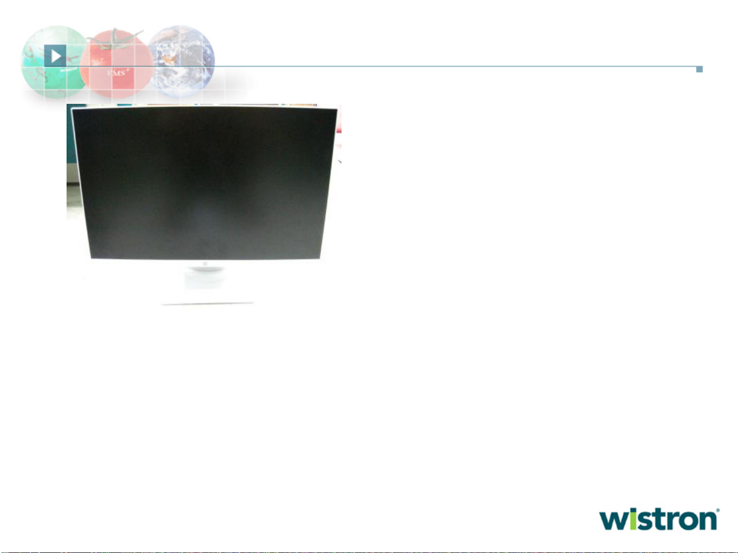
Remove Stand Base From Display Head
4.Remove Stand Base From Display Head.
3. Pull the release button
Page 6
4
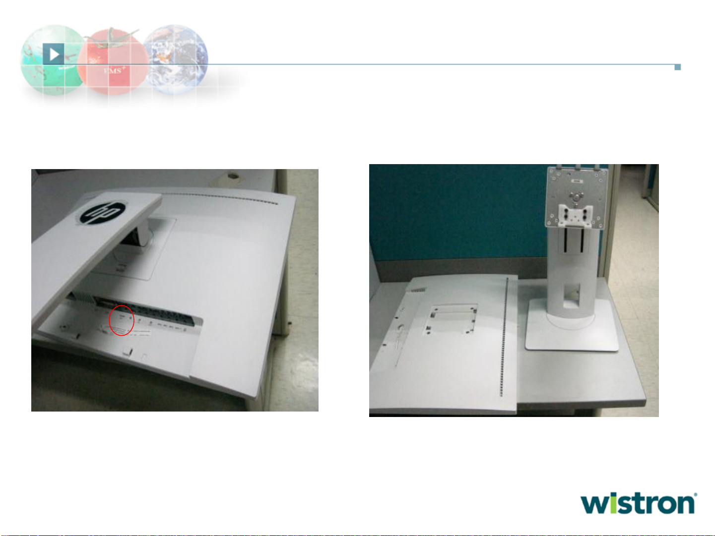
6.Remove Rear Cover From Display Head.
Remove Rear Cover From Display Head
5.Remove four wall mount screws from
display head .
Page 7
5
Remove Bracket from Display Head
7. Remove AL ,tape,internal cable
8.Remove screw
Page 8
6
Remove Mid-cover from head
9. Remove screw
Page 9

7
FC
Power Button
Function key
Remove front cover from head
10.Remove front cover from head
Page 10
8
FC
Power Button
Function key
Disassemble front cover
11.Remove function key and Mylar
Page 11
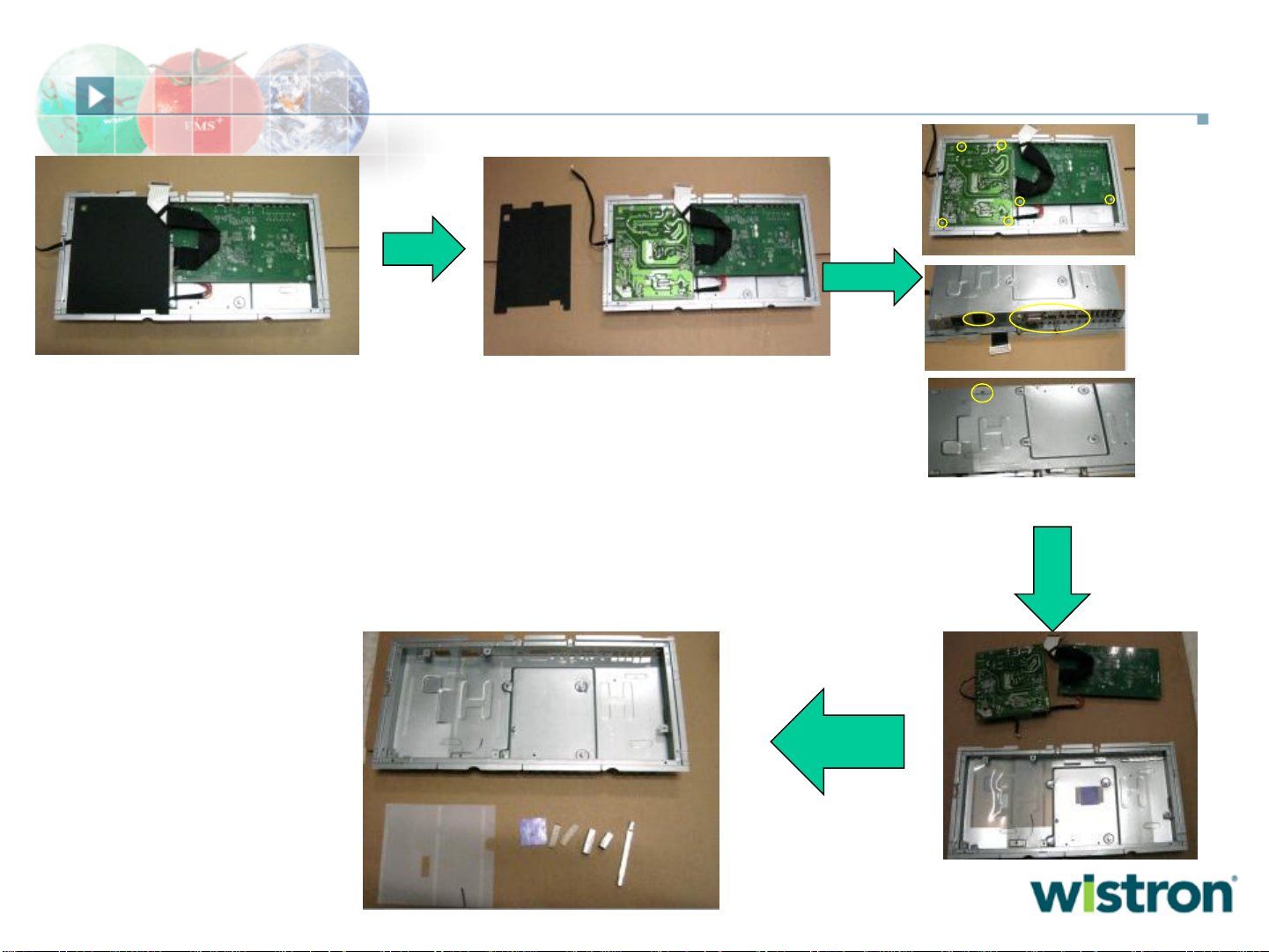
9
Disassemble Bracket ASSY
Remove Mylar
Remove Screws
Remove Mylar ,thermal
pad and gasket
Page 12
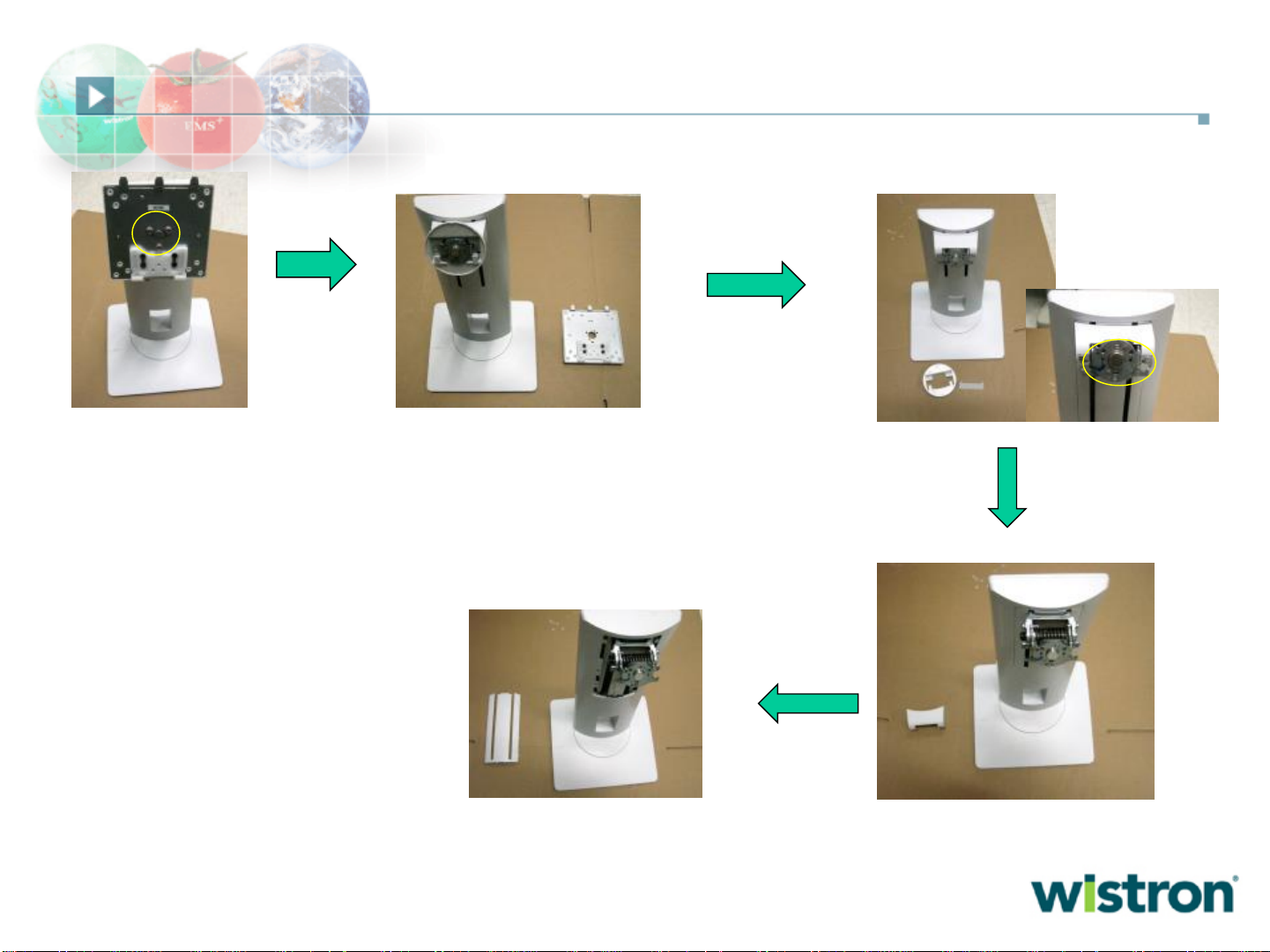
10
Disassemble Stand ASSY
Remove screws
Remove pivot cover and
Tilt 1 cover
Remove screw and
tilt cover
Remove lift cover
Page 13

11
Disassemble Stand ASSY
Remove rubber
Remove screw
Remove screw
Remove screw
Page 14

12
Disassemble Stand ASSY
Remove screw
Remove VESA cover ,
slider, Spring and release
botton
Page 15
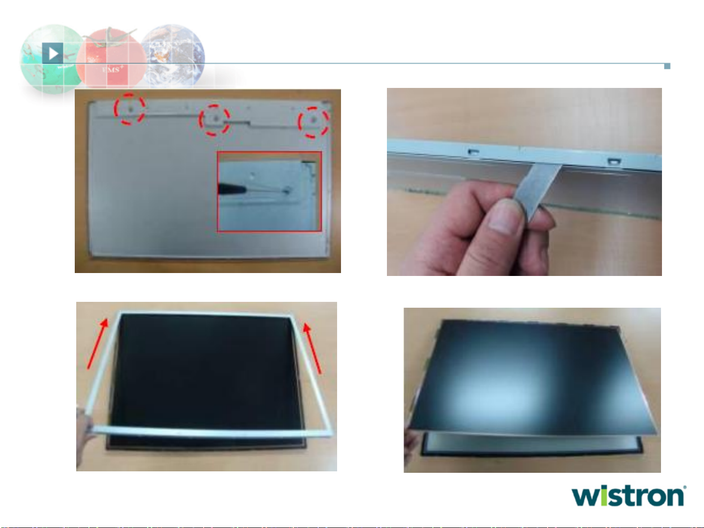
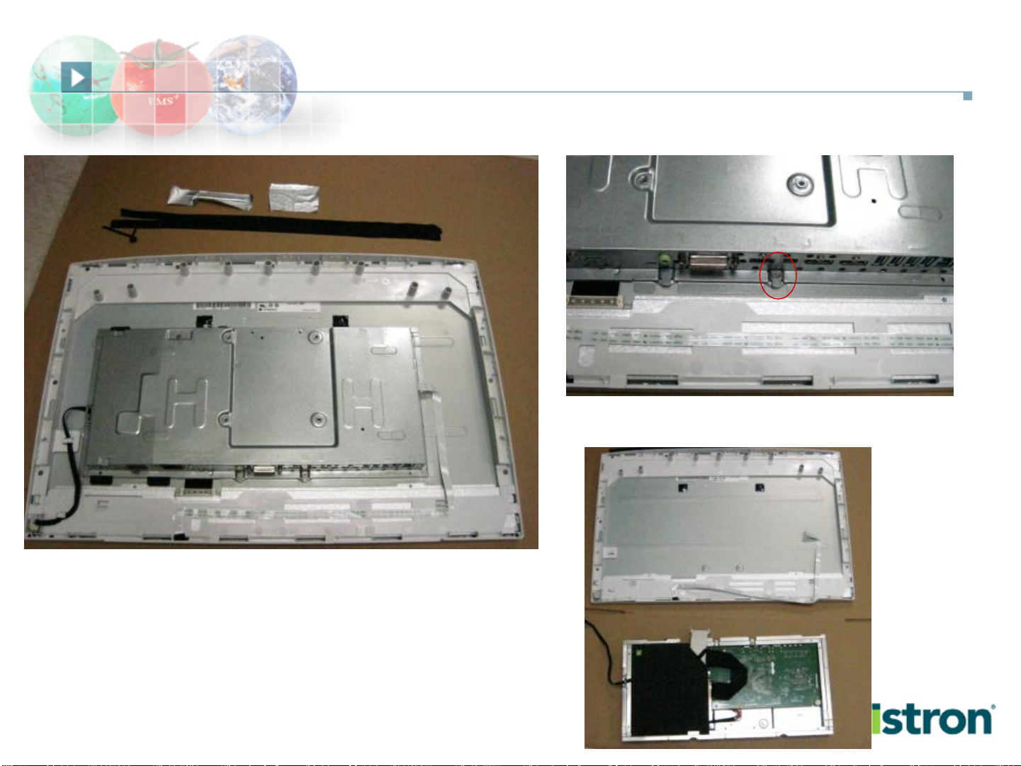
13
Disassemble Panel ASSY
1.Loosen C/Shield Screw(*3),Dismantle C/Shield
2.Dismantle C/Top
3.Separate C/Top(push the C/Top because of damages on
COF)
4.Separate B/Ass’y
Page 16

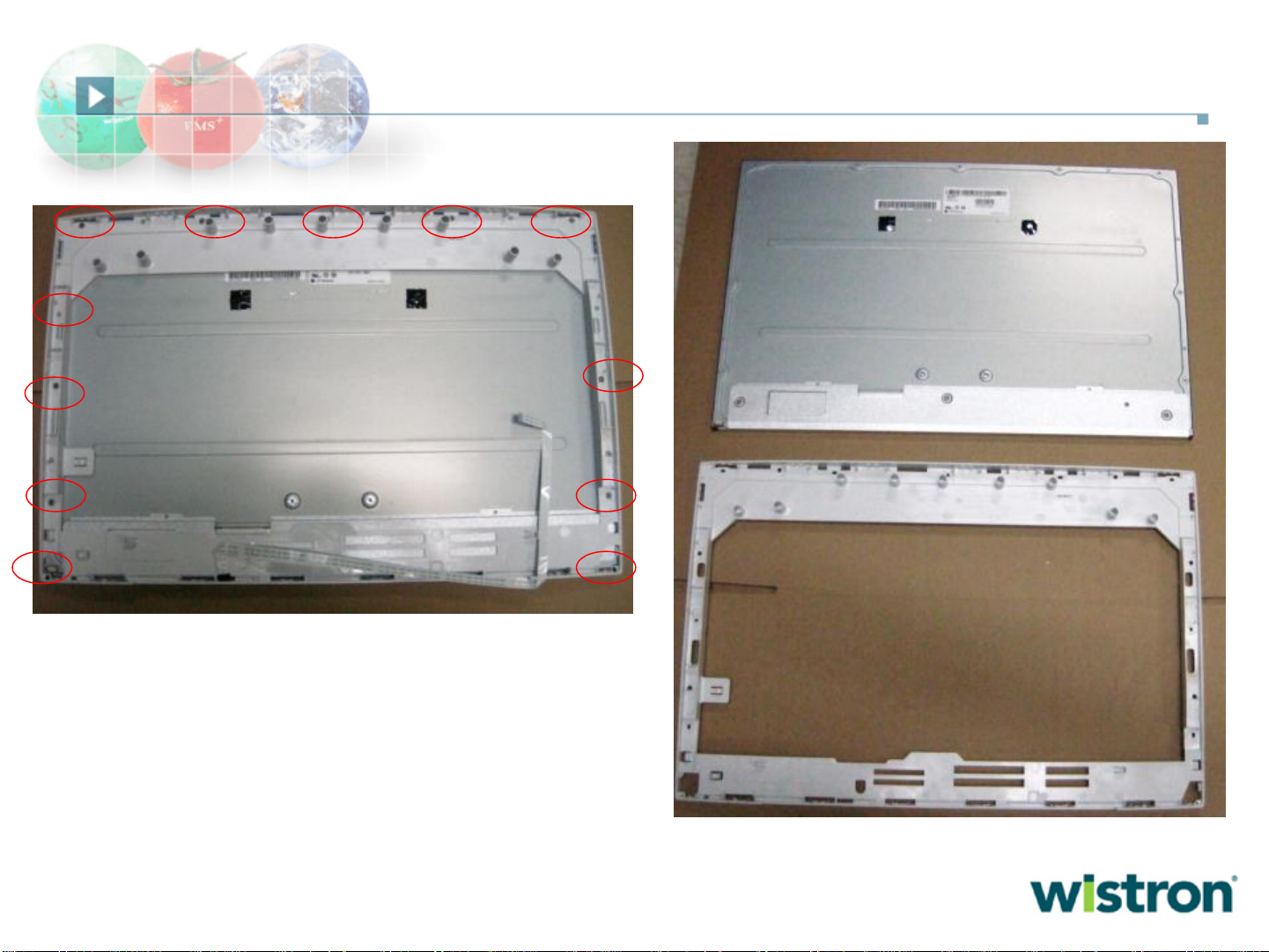
14
5.Loosen B/L Screw(*5)
6.Dismantle G/Panel
7.Removeal Optical sheets
8.Removeal LGP
Disassemble Panel ASSY
Page 17

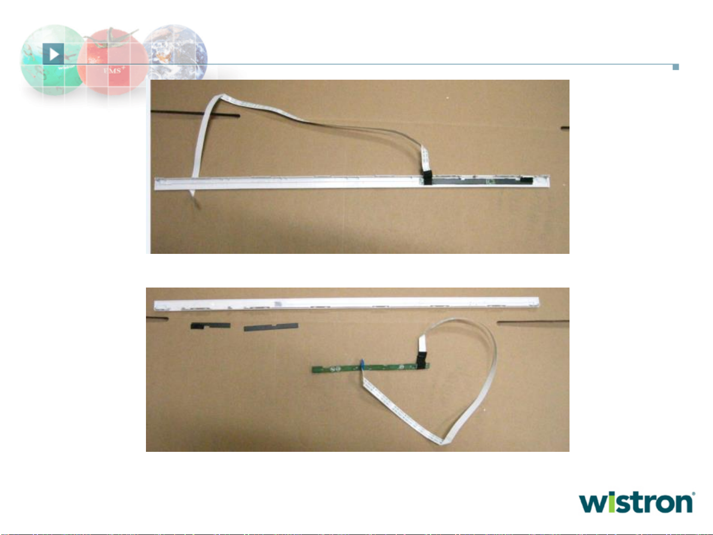
15
9.Removal Reflector
10.Separate LED Array from C/Bottom Assy
11.LED Array
Dissecting to complete.
Disassemble Panel ASSY
 Loading...