

Page 1

TM 11-6625-1514-15
DEPARTMENT OF THE ARMY TECHNICAL MANUAL
ORGANIZATIONAL, DS, GS,
AND DEPOT MAINTENANCE MANUAL
HEWLETT-PACKARD
VOLTMETER
400D, 400H, 4001
This copy is a reprint which includes current
pages from Changes 1.
VACUUM TUBE
MODELS
AND H02-400D
HEADQUARTERS, DEPARTMENT OF THE ARMY
MAY 1967
Page 2

WARNING
DANGEROUS VOLTAGES
EXIST IN THIS EQUIPMENT
Be careful when working on the power supplies and
their circuits, or on the 230 or 115-volt ac line
connections.
DO NOT TAKE CHANCES
Page 3

TM 11-5625-1514-15
C1
C
HANGE
HEADQUARTERS
DEPARTMENT OF THE ARMY
No. 1
Washington DC, 28 September 1982
Organizational, Direct Support, General Support and
Depot Maintenance Manual
HEWLETT–PACKARD VACUUM TUBE VOLTMETER MODELS
400D, 400H, 400L, and H02-400D
(NSN 6625-00-643-1670)
TM 11-6625-1514-15, 23 May 1967, is changed as follows:
1. Title of manual is changed as shown above.
2. New or changed material is indicated by a vertical bar in the margin.
3. Added or revised illustrations are indicated by a vertical bar next to the figure caption.
4. Remove old pages and insert new pages as indicated below:
Remove pages
None. . . . . . . . . . . . . . . . . . . . . . . . . . . . . . . . . . . . . . . . . . . . . . . . . . . . . . . . . . . . . .
i and 1-0 . . . . . . . . . . . . . . . . . . . . . . . . . . . . . . . . . . . . . . . . . . . . . . . . . . . . . . . . . . . . . . . . . . . . . . . . i, ii and 1-0
1-0.1 . . . . . . . . . . . . . . . . . . . . . . . . . . . . . . . . . . . . . . . . . . . . . . . . . . . . . . . . . . . . . . . . . . . . . . . . . . . . . . . . 1-0.1
10-5 . . . . . . . . . . . . . . . . . . . . . . . . . . . . . . . . . . . . . . . . . . . . . . . . . . . . . . . . . . . . . . . . . . . . . . . . . . . . . . . . . . 10-5
5. File this change sheet in front of the publication for reference purposes.
. Warning page a/(b blank)
Insert pages
By Order of the Secretary of the Army:
Official:
ROBERT M. JOYCE
Major General, United States Army
The Adjutant General
Distribution:
To redistributed in accordance with special list.
E. C. MEYER
General, United States Army
Chief of Staff
Page 4

Page 5
TM 11-6625-1514-15
SAFETY STEPS
IS THE VICTIM
TO FOLLOW IF
OF ELECTRICAL
SOMEONE
SHOCK
DO NOT TRY TO PULL OR GRAB THE INDIVIDUAL
IF POSSIBLE , TURN OFF THE ELECTRICAL POWER
IF YOU CANNOT TURN OFF THE ELECTRICAL
POWER, PULL, PUSH, OR LIFT THE PERSON TO
SAFETY USING A WOODEN POLE OR A ROPE OR
SOME OTHER INSULATING MATERIAL
SEND FOR HELP AS SOON AS POSSIBLE
AFTER THE INJURED PERSON IS FREE OF
CONTACT WITH THE SOURCE OF ELECTRICAL
SHOCK, MOVE THE PERSON A SHORT DISTANCE
AWAY AND IMMEDIATELY START ARTIFICIAL
RESUSCITATION
Change 1 a/(b blank)
Page 6

Page 7

This manual contains copyright material reproduced by permission of the Hewlett-Packard Company.
TM 11-6625-1514-15
Technical Manual
HEADQUARTERS
DEPARTMENT OF THE ARMY
No. 11-6625-1514-15
Washington, DC, 23 May 1967
ORGANIZATIONAL, DIRECT SUPPORT, GENERAL SUPPORT AND
DEPOT MAINTENANCE MANUAL
HEWLETT-PACKARD VACUUM TUBE VOLTMETER MODELS
400D, 400H, 400L, AND H02-400D
(NSN 6625-00-643-1670)
Paragraph
Section
Section
Section
Section
Section
I.
GENERAL DESCRIPTION
Scope . . . . . . . . . . . . . . . . . . . . . . . . . . . . . . . . . . . . . . . . . . . . . . . . . . . . . . . . . . . . . . . . . . . . . . . . . . .
Index of Technical Publications . . . . . . . . . . . . . . . . . . . . . . . . . . . . . . . . . . . . . . . . . . . . . . . . . . . . .
Maintenance Forms, Records, and Reports . . . . . . . . . . . . . . . . . . . . . . . . . . . . . . . . . . . . . . . . . . . .
Reporting Errors and Recommending Improvements . . . . . . . . . . . . . . . . . . . . . . . . . . . . . . . . . . .
Reporting Equipment Improvement Recommendations . . . . . . . . . . . . . . . . . . . . . . . . . . . . . . . . .
Administrative Storage. . . . . . . . . . . . . . . . . . . . . . . . . . . . . . . . . . . . . . . . . . . . . . . . . . . . . . . . . . . .
Destruction of Army Electronics Materiel . . . . . . . . . . . . . . . . . . . . . . . . . . . . . . . . . . . . . . . . . . . . .
Introduction . . . . . . . . . . . . . . . . . . . . . . . . . . . . . . . . . . . . . . . . . . . . . . . . . . . . . . . . . . . . . . . . . . . . . .
Description . . . . . . . . . . . . . . . . . . . . . . . . . . . . . . . . . . . . . . . . . . . . . . . . . . . . . . . . . . . . . . . . . . . . . . .
II.
INSTALLATION
Unpacking and Inspection . . . . . . . . . . . . . . . . . . . . . . . . . . . . . . . . . . . . . . . . . . . . . . . . . . . . . . . . . .
Line Voltage Requirement . . . . . . . . . . . . . . . . . . . . . . . . . . . . . . . . . . . . . . . . . . . . . . . . . . . . . . . . . .
Power Line Connections . . . . . . . . . . . . . . . . . . . . . . . . . . . . . . . . . . . . . . . . . . . . . . . . . . . . . . . . . . .
Installation . . . . . . . . . . . . . . . . . . . . . . . . . . . . . . . . . . . . . . . . . . . . . . . . . . . . . . . . . . . . . . . . . . . . . . .
Operation Check . . . . . . . . . . . . . . . . . . . . . . . . . . . . . . . . . . . . . . . . . . . . . . . . . . . . . . . . . . . . . . . . . .
III.
OPERATING INSTRUCTIONS
Instrument Turn-On . . . . . . . . . . . . . . . . . . . . . . . . . . . . . . . . . . . . . . . . . . . . . . . . . . . . . . . . . . . . . . .
General Operating Information.. . . . . . . . . . . . . . . . . . . . . . . . . . . . . . . . . . . . . . . . . . . . . . . . . . . . .
Low-Level Measurements and Ground Currents . . . . . . . . . . . . . . . . . . . . . . . . . . . . . . . . . . . . . . . .
Measurement of Voltage . . . . . . . . . . . . . . . . . . . . . . . . . . . . . . . . . . . . . . . . . . . . . . . . . . . . . . . . . . .
Measurement of Decibels . . . . . . . . . . . . . . . . . . . . . . . . . . . . . . . .
Impedance Correction Graph . . . . . . . . . . . . . . . . . . . . . . . . . . . . . . . . . . . . . . . . . . . . . . . . . . . . . . .
Use of Voltmeter Amplifier . . . . . . . . . . . . . . . . . . . . . . . . . . . . . . . . . . . . . . . . . . . . . . . . . . . . . . . . .
IV.
CIRCUIT DESCRIPTION
Block Diagram . . . . . . . . . . . . . . . . . . . . . . . . . . . . . . . . . . . . . . . . . . . . . . . . . . . . . . . . . . . . . . . . . . . .
Input Voltage Divider and Step Attenuator . . . . . . . . . . . . . . . . . . . . . . . . . . . . . . . . . . . . . . . . . . . .
Broadband Voltmeter Amplifier . . . . . . . . . . . . . . . . . . . . . . . . . . . . . . . . . . . . . . . . . . . . . . . . . . . . .
Indicating Meter Circuit . . . . . . . . . . . . . . . . . . . . . . . . . . . . . . . . . . . . . . . . . . . . . . . . . . . . . . . . . . . .
Power Supply . . . . . . . . . . . . . . . . . . . . . . . . . . . . . . . . . . . . . . . . . . . . . . . . . . . . . . . . . . . . . . . . . . . . .
V.
MAINTENANCE
Scope . . . . . . . . . . . . . . . . . . . . . . . . . . . . . . . . . . . . . . . . . . . . . . . . . . . . . . . . . . . . . . . . . . . . . . . . . . .
Precautions . . . . . . . . . . . . . . . . . . . . . . . .
Test Equipment Required . . . . . . . . . . . . . . . . . . . . . . . . . . . . . . . . . . . . . . . . . . . . . . . . . . . . . . . . . . .
Meter Zero Adjustment . . . . . . . . . . . . . . . . . . . . . . . . . . . . . . . . . . . . . . . . . . . . . . . . . . . . . . . . . . .
Cabinet Removal . . . . . . . . . . . .
Tube Replacement . . . . . . . . . . . . . . . . . . . . . . . . . . . . . . . . . . . . . . . . . . . . . . . . . . . . . . . . . . . . . . . . .
Replacement of Special Parts . . . . . . . . . . . . . . . . . . . . . . . . . . . . . . . . . . . . . . . . . . . . . . . . . . .
Trouble Shooting . . . . . . . . . . . . . . . . . . . . . . . . . . . . . . . . . . . . . . . . . . . . . . . . . . . . . . . . . . . . . . . . .
Testing the Power Supply . . . . . . . . . . . . . . . . . . . . . . . . . . . . . . . . . . . . . . . . . . . . . . . . . . . . . . . . . . .
Testing Voltmeter Performance
Calibration and Frequency Response Adjustments . . . . . . . . . . . . . . . . . . . . . . . . . . . . . . . . . . . . . .
. . . . . . . . . . . . . . . . . . . . . . . . . . . . . . . . . . . . . . . . . . . . . . . . . . . . . .
. . . . . . . . . . . . . . . . . . . . . . . . . . . . . . . . . . . . . . . . . . . . . .
. . . . . . . . . . . . . . . . . . . . . . . . . . . . . . . . . . . . . . . . . . .
. . . . . . . . . . . . . . . . . . . . . . . . . . . .
1-A.1
1-A.2
1-A.3
1-A.4
1-A.5
1-A.6
1-A.7
1-1
1-4
2-1
2-3
2-5
2-8
2-10
3-1
3-3
3-12
3-14
3-17
3-20
3-22
4-1
4-3
4-7
4-10
4-14
5-1
5-3
5-5
5-7
5-9
5-10
5-13
5-17
5-20
5-22
5-24
Page
1-0.1
1-0.1
1-0.1
1-0.1
1-0.1
1-0.1
1-0.1
1-1
1-1
2-1
2-1
2-1
2-1
2-1
3-1
3-1
3-2
3-2
3-3
3-3
3-4
4-1
4-1
4-1
4-1
4-2
5-1
5-1
5-1
5-1
5-2
5-2
5-2
5-3
5-3
5-5
5-8
Change 1 i
Page 8

TM 11-6625-1514-15
Section
Section
Section
Section
Section
ILLUSTRATED PARTS BREAKDOWN
VI.
General . . . . . . . . . . . . . . . . . . . . . . . . . . . . . . . . . . . . . . . . . . . . . . . . . . .
GROUP ASSEMBLY PARTS BREAKDOWN
VII.
Vacuum Tube Voltmeter 400D/H/L . . . . . . . . . . . . . . . . . . . . . . . . . . . . . . . . . . . . . . . . . . .
Main Chassis Assembly . . . . . . . . . . . . . . . . . . . . . . . . . . . . . . . . . .
Range Switch Assembly 400D-19A . . . . . . . . . . . . . . . . . . . . . . . . . . . . . . . . . . . . . . . . . . . . . . . . . . .
Printed Circuit Board Assembly 400D-75G . . . . . . . . . . . . . . . . . . . . . . . . . . . . . . . . . . . . . . . . . . . .
Printed Circuit Board Assembly 400D-75F . . . . . . . . . . . . . . . . . . . . . . . . . . . . . . . . . . . . . . . . . . . .
Printed Circuit Board Assembly 400D-65C . . . . . . . . . . . . . . . . . . . . . . . . . . . . . . . . . . . . . . . . . . . .
VIII.
NUMERICAL INDEXES
Part No. Numerical Index . . . . . . . . . . . . . . . . . . . . . . . . . . . . . . . . . . .
Hewlett-Packard Stock No. Index . . . . . . . . . . . . . . . . . . . . . . . . . . . . . . . . . . . . . . . . . . . . . . . . . . .
REFERENCE DESIGNATION INDEX . . . . . . . . . . . . . . . . . . . . . . . . . . . . . . . . . . . . . . . . . . . . . .
IX.
AUXILIARY EQUIPMENT
X.
General . . . . . . . . . . . . . . . . . . . . . . . . . . . . . . . . . . . . . . . . . . . . . . . . . . . . . . . . . . . . . . . . . . . . . . . . . .
Line Matching Transformer Model 11004A . . . . . . . . . . . . . . . . . . . . . . . . . . . . . . . . . . . . . . . . . . . .
Bridging Transformer Model 11005A . . . . . . . . . . . . . . . . . . . . . . . . . . . . . . . . . . . . . . . . . . . . . . . . .
Final Performance Check . . . . . . . . . . . . . . . . . . . . . . . . . . . . . . . . . . . . . . . . . . . . . . . . . . . . . . . . . . .
Paragraph
6-1
7-1
7-2
7-3
7-4
7-5
7-6
10-1
10-3
10-7
10-8
Page
6-1
7-1
7-3
7-8
7-9
7-10
7-12
8-1
8-2
9-1
10-1
10-1
10-5
10-5
ii
Change 1
Page 9

Page 10
1-0
Change 1
TM 11-6625-1514-15
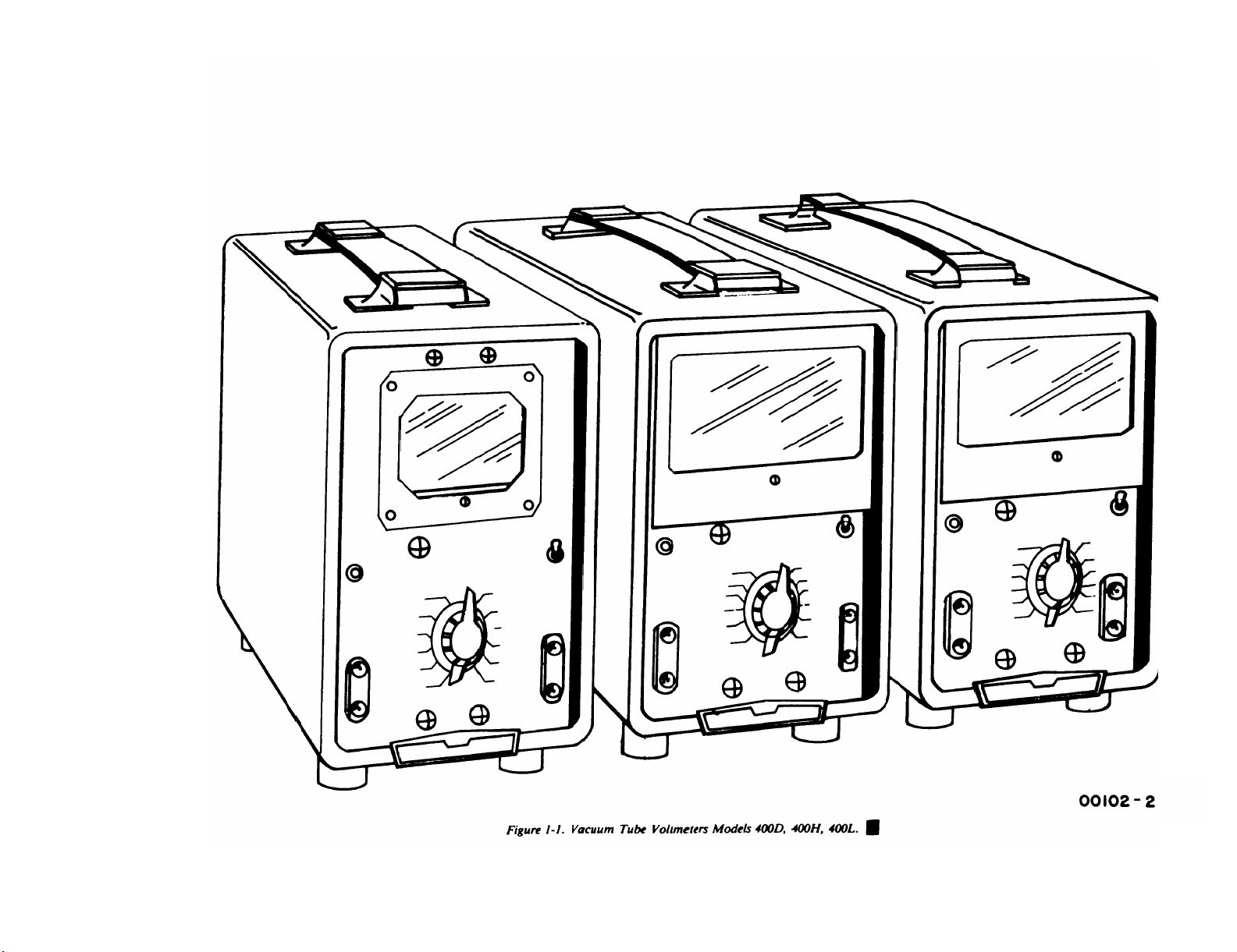
Figure 1-1.
Page 11

SECTION I
GENERAL DESCRIPTION
TM 11-6625-1514-15
1-A.1. Scope
This manual includes installation and operation instructions and covers operator’s, organizational,
direct support (DS), general support (GS), and depot
maintenance. It describes Hewlett-Packard (Federal
Supply Code 28480) Vacuum Tube Voltmeter Models
400D and H02-400D, serial numbers 310-45571 and
higher; and Models 400H and 400L, serial numbers
313-22177 and higher. A basic issue items list for this
equipment is not included in this manual.
1-A.2. Index of Technical
Publications
Refer to the latest issue of DA Pam 310-4 to determine whether there are new editions, changes or additional publications pertaining to the equipment.
1-A.3. Maintenance Forms, Records,
and Reports
a. Reports of Maintenance and Unsatisfactory
Equipment.
cedures used for equipment maintenance will be
those prescribed by TM 38-750, The Army
Maintenance Management System (Army). Air Force
personnel will use AFR 66-1 for maintenance reporting and TO-00-35D54 for unsatisfactory equipment
reporting.
b. Report of Packaging and Handling Deficien-
cies. Fill out and forward SF 364 (Report of
Discrepancy (ROD)) as prescribed in AR 735-11-2/
DLAR 4140.55/NAVMATINST 4355.73/AFR 40054/MCO 4430.3E.
c. Discrepancy in Shipment Report (DISREP)
(SF 361).
ment Report (DISREP) (SF 361) as prescribed in AR
55-38/NAVSUPINST 4610.33B/AFR 75-18/MCO
P4610.19C/DLAR 4500.15.
Department of the Army forms and pro-
Fill out and forward Discrepancy in Ship-
1-A.4. Reporting Errors and Recom-
mending Improvements
You can help improve this manual. If you find any
mistakes or if you know of a way to improve the procedures, please let us know. Mail your letter or DA
Form 2028 (Recommended Changes to Publications
and Blank Forms) direct to Commander, US Army
Communications-Electronics Command and Fort
Monmouth, ATTN: DRSEL-ME-MQ, Fort Monmouth, NJ 07703. A reply will be furnished direct to
you.
1-A.5. Report Equipment Improve-
ment Recommendations (EIR)
If your vacuum tube voltmeter needs improvement,
let us know. Send us an EIR. You, the user, are the
only one who can tell us what you don’t like about
your equipment. Let us know why you don’t like the
design. Tell us why a procedure is hard to perform.
Put it on an SF 368 (Quality Deficiency Report).
Mail it to Commander, US Army CommunicationsElectronics Command and Fort Monmouth, ATTN:
DRSEL-ME-MQ, Fort Monmouth, NJ 07703. We’ll
send you a reply.
1-A.6. Administrative Storage
Administrative storage of equipment issued to and
used by Army activities will have preventive
maintenance performed before storing. When
removing
storage, the PMCS should be performed to assure
operational readiness.
1-A.7. Destruction of Army Elec-
Destruction of Army electronics materiel to prevent
enemy use shall be in accordance with TM 750244-2.
the equipment from administrative
tronics Materiel
Change 1
1-0.1
Page 12

Page 13

TM 11-6625-1514-15
Paragraphs 1-1 to 1-5
Section I
1-1. INTRODUCTION.
1-2. This manual contains operating and servicing
instructions, and a parts breakdown, for the Models
400D, 400H, and 400L Vacuum Tube Voltmeters manufactured by the Hewlett- Packard Company. The Model
400D Voltmeter is similar to a military counterpart,
Electronic Voltmeter ME-30A/U, in appearance and
operation, but contains modified electrical circuits
to obtain improved performance. Applicable Federal
Stock Numbers for the voltmeters are as follows:
Model 400D: 6625-643-1670
Model 400H: 6625-557-8261
Model 400L: 6625-729-8360
1-3. The Models 400D, 400H, and 400L Voltmeters
are the same except for the differences listed in Figure 1-2.
a. Voltage Range: 400D/H - 0.1 millivolt to 300
volts; 400L - 0.3 millivolt to 300 volts, in 12 ranges
providing full-scale readings of the following voltages:
0.001
0.003 0.300 30.00
0.010
0.030 3.000
b. Decibel Range: -72 to +52 db, in 12 ranges.
c. Frequency Range: 10 cps to 4 mc.
d. Input Impedance: 10 megohms shunted by 15 pf
(15 µµf) on ranges 1.0 volt to 300 volts; 25 pf on ranges
0.001 volt to 0.3 volt.
e. Stability: Line voltage variations of ±10% do not
reduce the specified accuracy, and line voltage transients
are not reflected in the meter reading. Electron tube
deterioration to 75% of normal transconductance affects
accuracy less than 0.5% from 20 cps to 1 mc.
f. Amplifier: OUTPUT terminals are provided so
that the voltmeter can be used to amplify small signals
or to enable monitoring of waveforms under test with
an oscilloscope. Output voltage is approximately 0.15
volt rms on all ranges with full-scale meter deflection.
Amplifier frequency response is same as the voltmeter.
Internal impedance is approximately 50 ohms over
entire frequency range.
(See figure l-l. )
0.100
1.000
10.00
100.00
300.00
a. The front panel meters are different in each
model, as described in paragraph 1-6.
b. The accuracy specifications are different for
each model, as described in figure 1-2.
1-4. DESCRIPTION.
1-5. The Hewlett-Packard Models 400D, 400H, and
400L Vacuum Tube Voltmeters are general purpose,
portable electronic a-c voltmeters of high sensitivity
and stability. They are suited to both laboratory and.
field use. Models 400 D/H measure a-c voltages from
0.001 to 300 volts and Model 400L from .003 to 300
volts rms full scale, with a frequency bandwidth covering 10 cps to 4 megacycles. The voltmeters are compact, accurate, and rugged and have fast meter response, high input impedance, stable calibration accuracy, and freedom from the effects of normal line
—
voltage variations.
long instrument life with a minimum of servicing.
g. Accuracy: Model 400D -
± 2% of full scale, 20 cps to 1 mc;
± 3% of full scale, 20 cps to 2 mc;
± 5% of full scale, 10 cps to 4 mc.
Model 400H -
± 1% of full scale, 50 cps to 500 kc;
± 2% of full scale, 20 cps to
± 3% of full scale, 20 cps to
+ 5% of full scale, 10 cps to
Model 400L -
±2% of reading or ±1% of full scale,
whichever is more accurate,
50 cps to 500 kc.
±3% of reading or ±2% of full scale,
whichever is more accurate,
20 cps to 1 mc.
±4% of reading or ±3% of full scale,
whichever is more accurate,
20 cps to 2 mc.
±5% of reading 10 cps to 4 mc.
h. Power Requirement:
1000 cps, approximately 100 watts.
i. Size: 11-3/4 in. high, 7-1/2 in. wide, 12 in. deep.
j. Weight: 18 lbs; shipping weight approximately
23 lbs.
The voltmeters are designed for
1 mc;
2 mc;
4 mc.
115/230 volts ±10%, 50 to
00102-3
Figure 1-2. Table of Specifications
1-1
Page 14

TM 11-6625-1514-15
Section I
Paragraphs 1-6 to 1-10
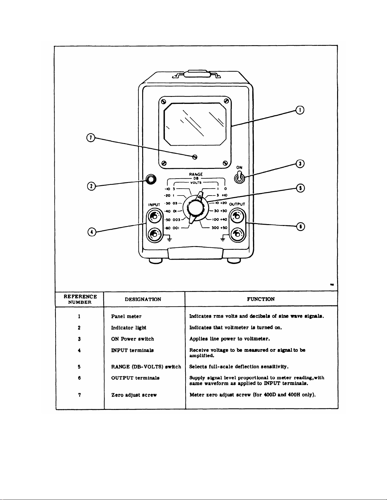
1-6. Each model voltmeter has three calibrated scales
on the panel meter.
two linear VOLTS scales, 0 to 1 and 0 to 3, and one
DECIBELS scale,
the Models 400H and 400L are larger and include a
mirror to eliminate parallax in viewing and to facilitate
use of the higher scale calibration accuracy of these
models. The Model 400L VOLTS scales are logarithmic
in calibration, from 0.3 to 1 and 0.8 to 3; and the
DECIBELS scale is linear. In all models, the VOLTS
scales are calibrated to indicate the root-mean-square
(rms) value of an applied sine wave. Actual meter
deflection is proportional to the average value of the
applied signal, thereby minimizing additional meter
deflection due to noise and harmonic distortion.
1-7. A voltmeter output signal is provided at the front
panel OUTPUT terminals.
to the meter reading and has a waveshape similar to the
applied signal.
rms for a full-scale meter reading, regardless of the
input signal level. The internal impedance at the
OUTPUT terminal is 50 ohms over the full frequency
range.
adversely affect the accuracy of the voltmeter. This
output is valuable for increasing the sensitivity of
bridges, etc., where distortion added to the waveform
is not a factor.
1-8. The voltmeter chassis is constructed of aluminum
alloy throughout. The panel is finished in non-reflecting,
light-grey baked enamel; the cabinet is finished in
dark-blue, baked wrinkle paint. The cabinet is equipped
with rubber feet and a leather carrying handle. Control
markings on the front panel are engraved and black
filled. INPUT and OUTPUT terminals are special
binding posts which accept either bare wire or banana
plugs; the 3/4-inch spacing between binding posts accepts
standard dual-banana plugs. The “ground” side of the
INPUT and OUTPUT terminals is connected to the
instrument chassis which is in turn connected to the
power line ground through the third (round) prong of
the plug on the power cable.
High-impedance loads (above 100K) will not
The Models 400D and 400H have
-12 to +2 db. The meters used in
This output is proportional
This signal level is about 0.15 volts
1-9. The voltmeter is equipped with a non-detachable
power cord. Test leads, which may be plain wire leads
or coaxial cable, and test probes must be supplied by
the user.
1-10. Instruments designated Models 400DR, 400HR,
and 400LR are rack mount configurations of the 400D,
400H, and 400L, respectively. They are identical to
their cabinet model counterparts in every other re-
spect. They are designed to be mounted in a standard 19 inch wide x 7 inch high relay rack space. Refer to Appendix C for Replacement Parts information.
1-2
Page 15

2-1. UNPACKING AND INSPECTION.
TM 11-6625-1514-15
Section II
Paragraphs 2-1 to 2-11
SECTION II
INSTALLATION
2-2. There are no special precautions for unpacking
the voltmeter. Save the shipping carton and packing
materials for possible storage or reshipment. When
unpacking, inspect instrument and packing materials
for signs of damage in shipment. Make an operation
check as directed in paragraph 2-10 to determine if
performance is satisfactory. If there is any indication
of damage or deficiency, refer to
paragraph 1-A.3.
2-3. LINE VOLTAGE REQUIREMENT.
2-4. The voltmeter is wired at the factory for use on
115-volt a-c power. This voltage may vary ±10% without
adverse effect upon voltmeter performance. The voltmeter can be wired for use on 230-volt a-c power by
reconnecting the dual primary windings on the power
transformer as shown in the schematic diagram in
Section V. When using 230-volt power, change from
a 1-amp to a 1/2-amp slow-blow fuse. If necessary,
provide an adapter for attaching the standard 115-volt
plug on the voltmeter to the 230-volt outlet.
2-5. POWER LINE CONNECTION.
2-6. The three-conductor power cable on the voltmeter
is terminated in a polarized three-prong male connector.
The third contact is an offset round pin added to a standard two-blade connector, which grounds the instrument
chassis when used with the appropriate receptacle.
To connect this plug in a standard two-contact receptacle,
use an adapter. The chassis ground connection is
brought out of the adapter in a green pigtail lead for
connection to a suitable ground.
The lower INPUT and OUTPUT signal terminals
on the panel of the voltmeter are connected
directly to the chassis of the voltmeter. Any
voltage applied to the lower terminal will be
shorted directly to ground. If the ground connection in the power cord is disconnected by
use of an adapter, the entire voltmeter cabinet
will carry whatever potential is applied to the
lower terminal and may be a hazard to the
operator.
2-8. INSTALLATION.
2-9. The voltmeter is a portable instrument requiring
no permanent installation. The voltmeter is for benchtop operation, standing on its rubber feet with its front
panel near the vertical plane. A bail is provided for
raising the front of the cabinet to obtain a better viewing
angle.
2-10. OPERATION CHECK.
2-11. The voltmeter is ready for use as received from
the factory. The simple check described below can be
made by incoming inspectors to determine if electrical
damage was incurred in shipment. If more complete
proof of instrument performance is required, the over-all
performance check described in paragraph 5-22 must be
used. Make a simple performance check as follows:
a. Connect voltmeter to the power line through a
variable transformer. Set transformer for 115 volts,
turn on and allow a five-minute warmup.
2-7. The power plug normally supplied with the volt-
meter is made of molded rubber and is an integral
part of the power cable. On certain military contracts,
a modification of the Model 400D, termed the H02-400D,
is equipped with a removable plug having the same pin
configuration but constructed of corrosion-resistant
material. In all other respects the H02-400D is the
same as the Model 400D and carries the same Federal
Stock Number.
00102-2
b. Measure any sine wave voltage, excepting the power
line,
from 0.01 to 300 volts whose exact voltage is known.
Note that the lower INPUT terminal is connected to the
power line ground.
c. While making the above measurement, adjust the
line voltage from 103 to 127 volts. The reading on the
meter must not change by more than the width of the
pointer.
2-1
Page 16
TM 11-6625-1514-15
Section III
3-0
Figure 3-1. Voltmeter Front Panel, Showing Controls and Connectors
00102-2
Page 17
SECTION III
OPERATING INSTRUCTIONS
TM 11-6625-1514-15
Section III
Paragraphs 3-1 to 3-9
3-1. INSTRUMENT TURN-ON.
3-2. The voltmeter is ready for use as received from
the factory and will give specified performance after a
few minutes warmup. See Section II for information
regarding connection to the power source and to the
voltage to be measured. Controls are shown in figure 3-1.
3-3. GENERAL OPERATING INFORMATION.
3-4. METER ZERO CHARACTERISTIC. When the
Model 400D and 400H Voltmeters are turned off, the
meter pointer should rest exactly on the zero calibration
mark on the meter scale. If it does not, zero-set the
meter as instructed in paragraph 5-7. The meter
supplied in the Model 400L Voltmeter is not provided
with a mechanical meter zero adjustment. When the
voltmeter is turned on with the INPUT terminals
shorted, the meter pointer may deflect upscale slightly;
this deflection does not affect the accuracy of a reading.
NOTE
When the voltmeter RANGE switch is set to the
lowest ranges and the INPUT terminals are not
terminated or shielded, noise pickup can be
enough to produce up to full-scale meter deflection. This condition is normal and is caused
by stray voltages in the vicinity of the instrument. For maximum accuracy on the .001-volt
range, the voltage under measurement should
be applied to the voltmeter through a shielded
test lead.
3-5. METER SCALES. The two voltage scales on each
of the voltmeter models are related to each other by
a factor of 1 10 (10 db). In conjunction with the calib-
rated RANGE switch steps, this provides an intermediate
range step spaced 10 db between “power of ten” ranges,
which are 20 db apart. The relationship of the DECIBELS
scale to the 0 to 1 VOLT scale is determined by making
0 db on the DECIBELS scale equal to the voltage required
to produce 1 milliwatt in 600 ohms (0.775 volts). Thus,
the DECIBELS scale reads directly in dbm (decibels
referred to one milliwatt) across a 600-ohm circuit,
and can be used to measure absolute level of sine wave
signals. It can also be used to measure relative levels
of any group of signals which have the same waveform,
across any constant circuit impedance. The RANGE
switch changes voltmeter sensitivity in 10-db steps
accurate to within ± 1/8 db. The RANGE switch position
indicates the value of a full-scale meter reading.
3-6. CONNECTIONS. Voltmeter test leads must be
provided by the user. The type of leads and probes
used will depend upon the application, as listed below:
a For connection to low-impedance signal sources,
plain wire leads often are sufficient.
00102-2
b. For high-impedance sources, or where noise pickup
is a problem, low-capacity shielded wire must be used
with a shielded, dual banana plug for connection to the
voltmeter terminals.
c. If a probe is used, it should also be shielded to
prevent pickup from the hand.
d. For signals above a few hundred kilocycles, the
capacity of the test leads must be kept to a minimum
by using very short leads, preferably unshielded. An
alligator clip should be used at the test end so that
connection can be made without adding the capacity of
the user’s hands.
3-7. MAXIMUM INPUT VOLTAGE. Do not apply more
than 600 volts de to the INPUT terminals. To do so exceeds the voltage rating of the input capacitor.
3-8. If an applied voltage momentarily exceeds the
selected full-scale voltmeter sensitivity, a few seconds
may be required for circuit recovery, but no damage
will result.
3-9. INPUT VOLTAGE WAVEFORM. The voltmeter
is calibrated to indicate the root-mean-square value
of a sine wave; however, meter pointer deflection is
proportional to the average value of whatever waveform
is applied to the input.
is not a sine wave, the reading will be in error by an
amount dependent upon the amount and phase of the
harmonics present, as shown in figure 3-2 below.
When harmonic distortion is less than about 10%, the
error which results is negligible.
INPUT VOLTAGE
CHARACTERISTICS
Fundamental = 100
Fundamental +10%
2nd harmonic
Fundamental +20%
2nd harmonic
Fundamental +50%
2nd harmonic
Fundamental +10%
3rd harmonic
Fundamental +20%
3rd harmonic
Fundamental +50%
3rd harmonic
Note: This chart is universal in application since
these errors are inherent in all average-responding type voltage-measuring instruments.
Figure 3-2. Effect of Harmonics on Voltage
Measurements
If the input signal waveform
TRUE
RMS
VALUE
100
100.5
102
112
100.5
102
112
METER
INDICATION
100
100
100-102
100-110
96-104
94-108
90-116
3-1
Page 18
TM 11-6625-1514-15
Section III
Paragraphs 3-10 to 3-16
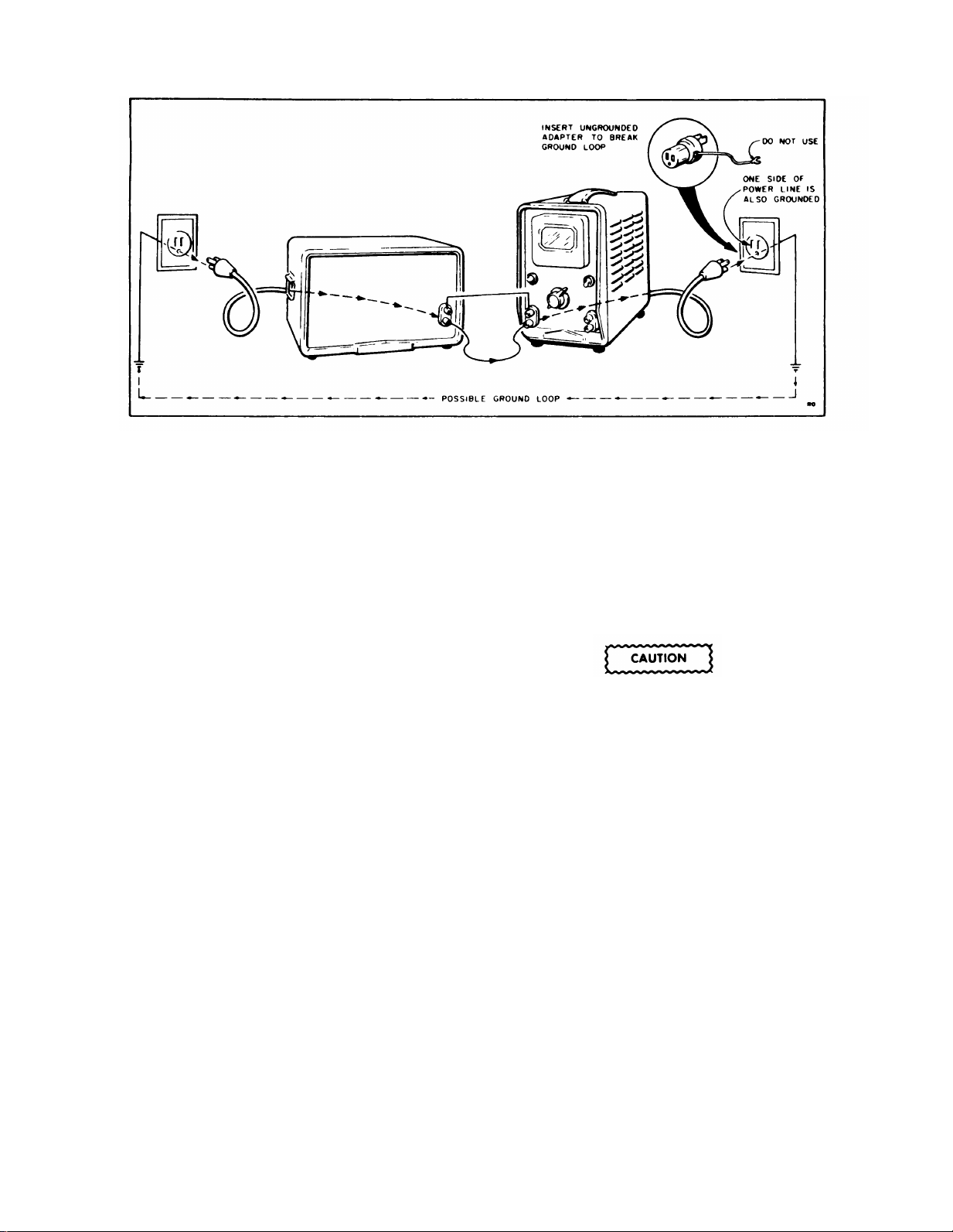
Figure 3-3. Test Setup for Avoiding Ground Loop
3-10. Since the voltmeter meter deflection is propor-
tional to the average value of the input waveform, it
is not adversely affected by moderate levels of random
noise. The effect that noise has on the accuracy of the
meter reading depends upon the waveform of the noise
and upon the signal-to-noise ratio. A square wave has
the greatest effect, a sine wave intermediate effect, and
“White” noise has the least effect on the meter reading.
3-11. If the noise signal is a 50% duty cycle square wave
and the signal-to-noise ratio is 10:1 (between peak
voltages), the error will be about 1% of the meter
reading. If the noise signal is “white” noise and the
signal-to-noise ratio 10:1, the error is negligible.
3-12. LOW-LEVEL MEASUREMENTS AND GROUND
CURRENTS.
3-13. When the voltmeter is used to measure signal
levels below a few millivolts, ground currents in the
meter test leads can cause an error in meter reading.
Such currents are created when two or more ground
connections are made between the instruments of a
test setup and/or between the instruments and the power
line ground. Two ground connections complete an
electrical circuit (ground loop) for the voltages which
are generated across all instrument chassis by stray
fields, particularly the fields of transformers. These
ground currents can be minimized by disconnecting
the ground lead in the power cord from either the
voltmeter or the signal source being measured, at the
power outlet as shown in figure 3-3, and by making
sure that in the test setup no other ground loop is
formed that can cause a ground current to flow in the
voltmeter test leads. Although the resultant voltage
developed across a test lead is in the order of microvolt, it is enough to cause noticeable errors in
measurements of a few millivolts. The presence of
ground currents can sometimes be determined by
simply changing the grounds for the instruments in the
3-2
setup and watching for a change in meter reading. If
changing the ground system causes a change in meter
reading, ground currents are present.
3-14. MEASUREMENT OF VOLTAGE.
3-15. The meter has two VOLTS scales, 0 to 1 and
0 to 3. When the RANGE switch is set to .001, .01,
.1, 1, 10, or 100 VOLTS, read the 0 to 1 scale. When
the RANGE switch is set to .003, .03, .3, 3, 30, or 300
VOLTS, read the 0 to 3 scale.
The lower (black) signal INPUT and OUTPUT terminals and the instrument case are
connected to the power system ground when
the instrument is used with a standard threeterminal (grounding) receptacle. Connect
only ground-potential circuits to the black
INPUT and OUTPUT terminals.
3-16. Operate the instrument as follows:
a. Connect the voltmeter to the a-c power source.
b. Turn the Power switch ON and allow a warmup
period of approximately five minutes.
c. Disconnect any external equipment from the OUT-
PUT terminals.
d. Set the RANGE switch to the VOLTS range which
will read the voltage to be measured at mid-scale or
above. If in doubt, select a higher VOLTS range.
e. Connect the voltage to be measured to the INPUT
terminals.
00102-2
Page 19
AVOID A SHORT CIRCUIT ACROSS THE POWER LINE! To measure power line voltage, first
connect only the upper (red) INPUT terminal to
each side of the power line, in turn, leaving it
connected to the side that causes meter indication. Then connect the lower (black) INPUT
terminal (grounded internally) to the other side
of the line. If this procedure is not followed,
the power line may be short-circuited through
the grounded INPUT terminal of the voltmeter.
TM 11-6625-1514-15
Section III
Paragraphs 3-17 to 3-21
f. Note the meter indication on the DECIBELS scale
(-12 to +2 db). The signal level is the algebraic sum of
the meter indication and the db value indicated by the
RANGE selector. Study the following examples:
Example 1
If the indication on the DECIBELS scale is +2 and the
RANGE switch is in the +20 DB position, the level is
+22 dbm.
Example 2
If the indication on the DECIBELS scale is +1.5 and the
RANGE switch is in the -40 DB position, the level is
-38.5 dbm.
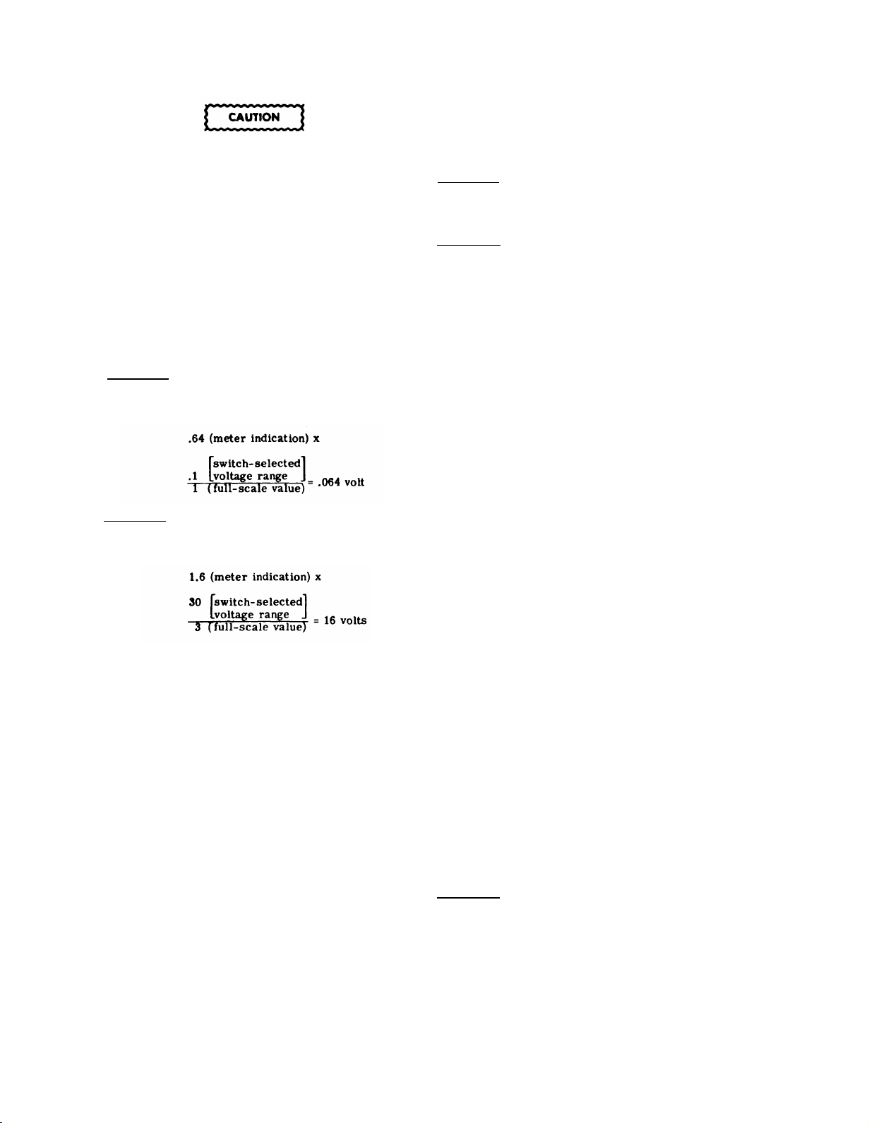
f. Read the meter indication on the appropriate VOLTS
scale, in accordance with the full-scale value indicated
on the RANGE switch. Evaluate the reading in terms
of the full-scale value indicated on the RANGE switch.
Study the following examples:
Example 1
When the RANGE switch is in the .1 VOLTS range, read
the 0 to 1 VOLTS scaIe. If the meter indicates .64 on
that scale, the voltage being measured is:
Example 2
When the WGE switch is in the 30 VOLTS range, read
the 0 to 3 VOLTS scale. If the meter indicates 1.6 on
that scale, the voltage being measured is:
3-17. MEASUREMENT OF DECIBELS.
3-18. The DECIBELS meter scale is provided for
measuring dbm directly across 600 ohms and for
measuring db ratio for comparison purposes when
each measurement is made across the same circuit
impedance. To measure signal level directly in dbm
(0 dbm equals 1 milliwatt into 600 ohms) proceed as
follows:
a. Connect the voltmeter to the a-c power source.
b. Turn the Power switch ON and allow a warmup
period of approximately five minutes.
c. Disconnect any external equipment from the OUT-
PUT terminals.
d. Set the RANGE switch to the DB range which will
give an upscale reading of the signal to be measured.
If in doubt, select a higher-level scale.
e. Connect the voltage to be measured to the INPUT
terminals.
00102-2
3-19. To measure db across impedances other than
600 ohms, follow the above procedure and evaluate the
results as follows:
NOTE
Since the measurement is made across other
than 600 ohms, the level obtained in step f is in
db, but not in dbm.
a. To obtain the difference in db between measurements made across equal impedances, algebraically
subtract the levels being compared.
b. To obtain the reading of a single measurement
in dbm, note the impedance across which the measurement is made and refer to the Impedance Correction
Graph, described in paragraph 3-20.
c. To obtain the difference in dbm between measure-
ments made across different impedances, convert each
measurement to dbm using the Impedance Correction
Graph described in paragraph 3-20. Then algebraically
subtract the dbm levels being compared.
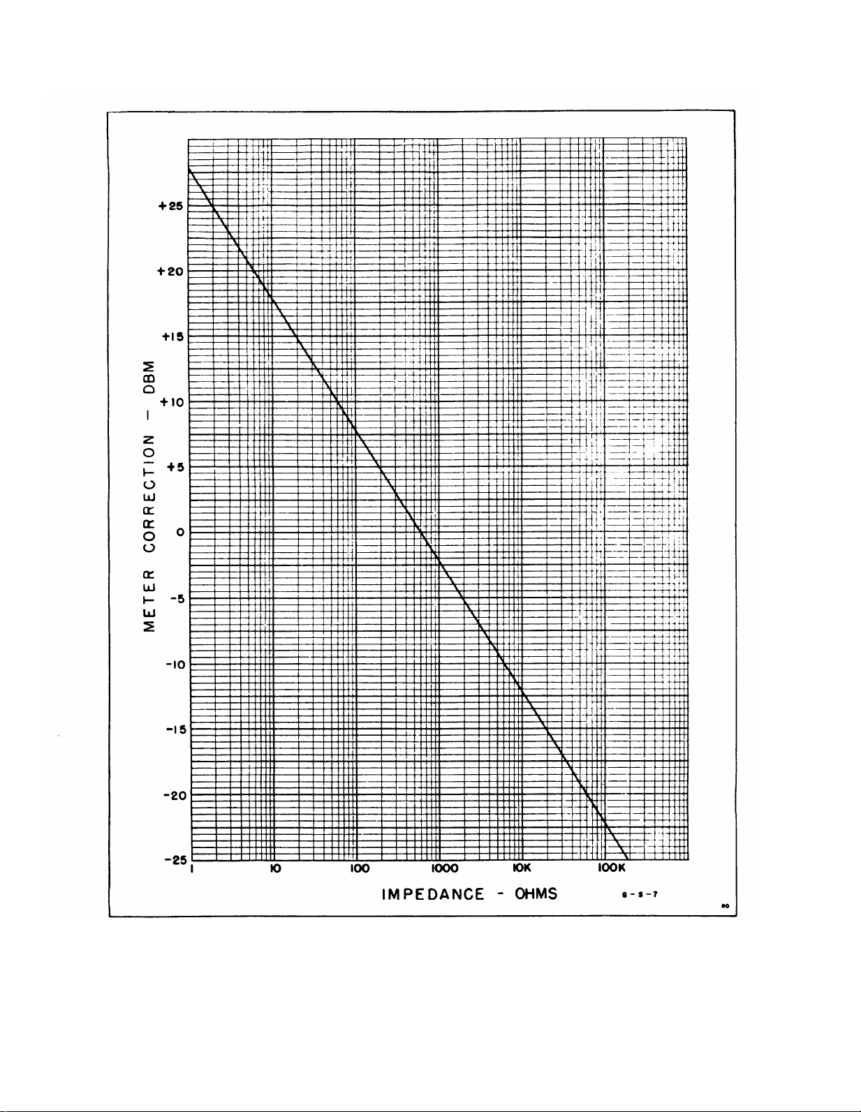
3-20. IMPEDANCE CORRECTION GRAPH.
3-21. As the voltmeter DECIBELS scale is calibrated
to indicate dbm for measurements made across 600-ohm
circuits, a correction factor must be used when measurements are made across circuit impedances other
than 600. ohms, if absolute dbm levels are desired. The
correction factor is not necessary in measuring relative
db levels (not dbm) across the same impedance, but it is
required for comparison of db levels measured across
different impedances.
in figure 3-4 gives the correction factor for conversion
of the meter reading to dbm when the impedance of
the circuit under test is known. To use the graph, read
the conversion factor corresponding to the test circuit
impedance and add it to the meter reading determined
by the method of paragraph 3-17. Observe the algebraic
sign of the correction factor in making the algebraic
addition. Use the following examples:
Example 1
If the measurement is made across 90 ohms, the
indication on the DECIBELS scale is +2, and the RANGE
switch is at the +30 DB position, the level in dbm is
obtained as follows:
The Impedance Correction Graph
3-3
Page 20

TM 11-6625-1514-15
Section III
Paragraphs 3-22 to 3-25
+ 2 (meter indication)
+30
(RANGE switch position)
+32 (sum)
+8
(correction factor from the Impedance
+40 dbm
Example 2
For the same conditions as given above, except that
the measurement is made across an impedance of 60,000
ohms, the level in dbm is obtained as follows:
+ 2 (meter indication)
+30
(RANGE switch position)
+32 (sum)
-20
(Correction factor from the Impedance
+12 dbm
3-22. USE OF VOLTMETER AMPLlFIER.
3-23. The amplifier in the voltmeter may be used for
amplifying weak signals. With full-scale meter deflection, the open-circuit output of the amplifier is approxi-
mately 0.15 volt rms regardless of the RANGE switch
position. The impedance looking into the OUTPUT
terminals is approximately 50 ohms. The frequency
Correction Graph)
Correction Graph)
response and calibration of the voltmeter may be
affected by the impedance of a load applied to the
OUTPUT terminals. To check the effect of the applied
load: observe the meter reading obtained with no load
connected to the OUTPUT terminals and then note any
shift of reading when the external circuit is connected
to the OUTPUT terminals. If the shift is negligible,
the measurement is not being affected appreciably by
the load. Whenever the input signal is changed, i.e., a
different frequency or band of frequencies is applied,
repeat the quick check described above.
3-24. Maximum gain from the amplifier is obtainable
only on the lowest (.001 volts) range, since output level
is the same for all bands. This is due to the 10-db
amplification loss per step inserted by the RANGE
switch as it is turned clockwise. Amplification may
also be obtained on the .003, .01, .03, and 1 volt ranges.
3-25. When the voltmeter is used as an amplifier,
select a range which gives a meter deflection near
full scale. Off-scale signals more than twice the value
of the position of the RANGE switch will cause severe
distortion.
3-4
00102-2
Page 21
TM 11-6625-1514-15
Section III
Figure 3-4. Impedance Correction Graph
3-5
Page 22
4-0
Section IV
TM 11-6625-1514-15
00102-2
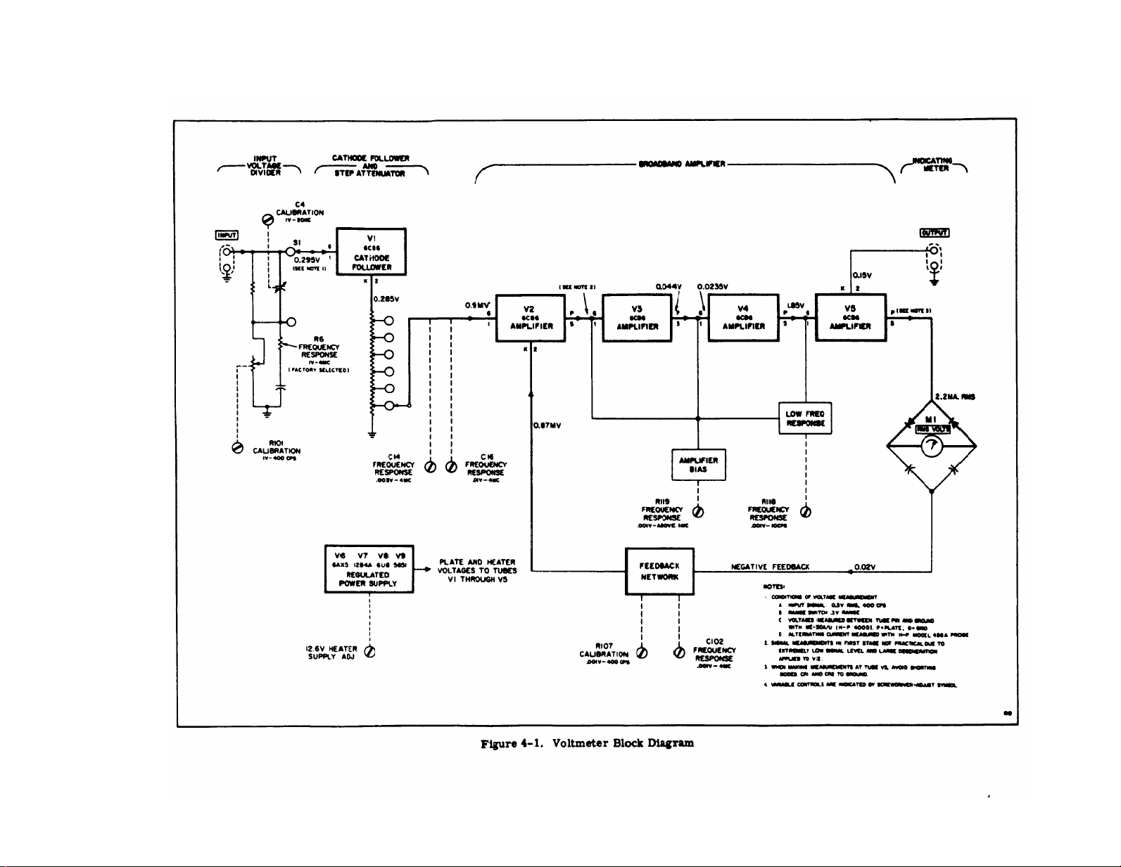
Figure 4-1.
Page 23

SECTION IV
CIRCUIT DESCRIPTION
4-1. BLOCK DIAGRAM.
4-2. The electrical circuits of the voltmeter are shown
in the block diagram in figure 4-1; they consist of an input
voltage divider controlled by the RANGE switch, a cathode
follower input tube, a precision step attenuator controlled
by the RANGE switch, a broadband amplifier, an indicating meter, and a regulated power supply. The voltage
applied to the INPUT terminals for measurement is
divided by 1000 before application to the input cathode
follower when the RANGE switch is set to the 1-volt
range and higher; the input voltage is applied directly
to the cathode follower on the lower ranges. The voltage
from the cathode follower is divided in the precision
attenuator to be less than 1 millivolt for application to
the voltmeter amplifier.
is rectified in a full-wave bridge rectifier with a d-c
milliammeter across its midpoints. The resultant
direct current through the meter is directly proportional
to the input voltage.
4-3. INPUT VOLTAGE DIVIDER AND STEP
ATTENUATOR.
4-4. The input voltage divider limits the signal level
applied to the input cathode follower to less than 0.3
volt rms when voltages above this level are measured
with the RANGE switch set at the 1-volt range or above.
The divider consists of a resistive branch with one
element made adjustable to obtain exact 1000:1 division
at middle frequencies and a parallel capacitive branch
with one element made adjustable to maintain exact
1000:1 division to beyond 4 megacycles. The input
impedance of the voltmeter is established by this divider
and is the same for all positions of the RANGE switch.
On the six low-voltage positions of the RANGE switch,
the input divider provides no attenuation of the input
voltage. (See figure 5-10 for the complete schematic.)
4-5. The step attenuator in the cathode circuit of the
input cathode follower reduces the voltage to be measured
to 1 millivolt or less for application to the voltmeter
amplifier. Each step of the attenuator lowers the signal
level by exactly 10 db (1: 10). The attenuator consists
of six precision wirewound resistors which are selected
to very high accuracy and carefully mounted on a 12-
position rotary switch. The RANGE switch rotor has two
contractors (see figures 5-9 and 5-10); the first contacts
each resistor in turn while the input divider is in the
non-attenuating position; the second rotor finger repeats
these contacts while the input attenuator is in the attenuating position.
(C15) is automatically connected to provide flat frequency
response beyond 4 megacycles. In the .003- and the .01volt ranges, separate adjustable capacitors (C14, C16)
are automatically connected to the attenuator to permit
setting the frequency response at 4 megacycles. C14 and
C16 are also connected to the attenuator on the 3- and
10-volt ranges.
connected) flattens frequency response on the .03- and
30-volt ranges.
00102-2
On the .001-volt range a fixed capacitor
Fixed capacitor C106 (permanently
The output of the amplifier
TM 11-6625-1514-15
Paragraphs 4-1 to 4-11
4-6. Cathode follower V1 provides a constant, high input
impedance to the input voltage divider and INPUT terminals of the voltmeter and provides a relatively low
impedance in its cathode circuit to drive the step attenuator.
4-7. BROADBAND VOLTMETER AMPLIFlER.
4-8. Amplification of the signal voltage is provided
by a four-stage stabilized amplifier consisting of tubes
V2 through V5 and associated circuits. The amplifier
provides between 55- and 60-db gain with about 55 db
of negative feedback at mid-frequencies. The feedback
signal is taken from the plate of the output amplifier (V5)
through the meter rectifiers and gain-adjusting circuit
to the cathode of the input amplifier (V2). Variable
resistor R107 in the feedback network adjusts the negative
feedback level to set the basic gain of the amplifier at
mid-frequencies, while adjustable capacitor C102 permits
setting amplifier gain at 4 megacycles. Variable resistor
R118 in the coupling circuit between V4 and V5 permits
adjusting the gain of the amplifier at 10 cycles per
second by controlling the phase shift of low-frequency
signals between these two stages (increasing phase
shift decreases degeneration and increases gain).
4-9. Variable resistor R119 in the grid return path for
V3, V4, and V5 adjusts the total transconductance of
these tubes in order to restrict the maximum gainbandwidth product of the amplifier. The gain-bandwidth
product must be restricted to give a smooth frequency
response rolloff above 4 megacycles and to prevent
possible unstable operation at frequencies far above
4 megacycles when tubes having unusually high trans-
conductance are used (tube transconductance tolerances
during manufacture permit wide variations in new tubes;
the adjustment permits the use of such tubes). The
plate voltage from V5 is rectified by the meter rectifiers and drives the feedback network. The cathode
voltage of V5 is fed to the meter OUTPUT terminals
for monitoring purposes.
thus the signal voltage at the cathode, is affected by
the loading of the meter rectifiers. For signal levels
causing third- scale or more meter deflection, this dis-
tortion consists of a very small irregularity near 0 volts
on the waveform as each diode begins conduction.
4-10. INDICATING METER CIRCUIT.
4-11. The meter rectifier circuit consists of two silicon
diodes and two capacitors connected as a bridge with the
indicating meter across the mid-points as shown in
figure 4-2. The diodes provide full-wave rectification
of the signal current for operating the meter. Electron
flow through the meter is supplied in the following manner
(see figure 4-2). During the positive-going half cycle
of plate voltage on V5, rectifier CR1 conducts electrons
from both C32 and C33 back to the B+ buss. The portion
of electrons from C33 flows through the meter on the way
to B+. At this point in the cycle, both C32 and C33 are
charged to the potential of B+ less some small drop in
R51 and R52.
The voltage gain factor across V1 is 0.95.
The current through V5, and
Section IV
4-1
Page 24

TM 11-6625-1514-15
Section IV
Paragraphs 4-12 to 4-16
4-12. During the negative-going half cycle of the plate
voltage of V5, rectifier CR2 conducts electrons back to
both C32 and C33 from the plate of V5. That portion
of electrons going back to C32 flows through the meter
on the way (in the same direction that the electrons
flowed in the first, positive, half cycle). At this point
in the cycle, both C32 and C33 are discharged. The
pulsating current through the meter is smoothed by
C34 to prevent meter pointer vibration when measuring
low-frequency signals.
the arithmetic average value of the waveform amplitude of the signal.
based on the mathematical ratio between the average and
rms values of true sine wave current.
4-13. In addition, the bridge serves as a segment of a
voltage divider (in series with L11 and R108) connected
across the output of the amplifier. The negative feedback
voltage fed to the input of the amplifier is obtained across
L11 and R108. The alternating charge and discharge of
C32 and C33 produce at their junction with L11 an alternating current of the same phase and waveform as
that at the plate of V5. This phase is negative with
respect to the input signal applied to the first stage of
the amplifier (V2), and drives the negative feedback
network.
4-14. POWER SUPPLY.
4-15. The power supply consists of tubes V6 through V8
and the associated circuits, as shown in the complete
The current is proportional to
Meter calibration in rms volts is
schematic diagram, figure 5-10. The power supply
furnishes regulated +250V d-c voltage for the grid and
plate bias circuits of tubes V1 through V5, unregulated
12.6V d-c voltage for the heater supply of tubes V1
through V4, and 6.3V a-c voltage for the heater supply
of tubes V5 through V8. The power supply is designed
to operate from either a 115-volt (±10%) or a 230-volt
(±10%) a-c power source of 50 to 1000 cps. The primary
winding of power transformer T1 is arranged in two
sections, which can be strapped either in parallel or in
series, to permit operation on 115V or 230V, respectively.
4-16. The output of rectifier V6 is applied to the voltage
regulator circuit consisting of V7 through V9 which
supplies a constant, +250 volts dc to the stabilized amplifier circuit of the voltmeter. Tube V7 is the series
regulator tube, and V9 provides a fixed reference voltage
drop, with which the output voltage is compared in ampli-
fier V8B. V8A is a cathode follower which couples the
reference voltage from V9 to V8B without loading V9.
The regulated output voltage is applied to the control
grid of V8B, while the reference voltage is applied to
its cathode. The difference between the control grid
and cathode voltages controls the operating point of
V8B and thus its plate voltage, which in turn supplies the
grid voltage for regulator V7. Any change in the regulated output of V7 produces a correcting change in the
grid bias of V7 through the action of V8B, thus maintaining
an essentially constant output voltage despite changes in
line voltage or load on the supply. The gain of V8B is
high enough to keep the output at the V7 cathode regulated
4-2
Figure 4-2. Simplified Schematic of Meter Bridge Circuit
00102-2
Page 25

TM 11-6625-1514-15
Section IV
Paragraph 4-17
to within ±1 volt dc as the V7 plate voltage is varied ±10%,
with about 60 ma of load current. The response of the
regulating circuits is fast enough to reduce ripple in
the output voltage to less than 1 millivolt, supplementing
the filtering action of C30. C36 couples the ripple component in the regulated output directly to V8B to avoid
attenuation in R62. R57 shunts a small portion of the
load current around V7 to prevent excessive V7 plate
dissipation at high line voltages. R63 and C35 constitute
a low-pass filter which prevents noise generated in V9
from reaching V8B.
4-17. The heater supply for the voltmeter tubes is
divided into two sections. One section supplies d-c
voltage for the tubes in the input cathode follower and
the amplifier. The other section supplies a-c voltage
for the tubes in the power supply. The voltage required
for the heaters of tubes V1 through V4 is obtained from
6.3V and 7.3V secondary windings of transformer T1,
which are series connected. The voltage developed
across the two series-connected windings is rectified
by full-wave rectifier CR3, reduced to 12.6 volts by
R66 and R68 in parallel, and applied to the seriesparallel-connected heaters of V1 through V4, as shown
in figure 5-10.
four heaters establishes a voltage of 6.3V for each.
The heater of V5 receives 6.3V ac from one of the wind-
ings which drives CR3.
V8 receive 6.3V ac from a separate 6.3V secondary
winding on T1.
The series-parallel connection of the
The heaters of V6, V7, and
00102-2
4-3
Page 26

Page 27

SECTION V
MAINTENANCE
TM 11-6625-1514-15
Section V
Paragraphs 5-1 to 5-8
5-1. SCOPE.
5-2. This section contains complete instructions for
repairing and calibrating the voltmeter. This material
is covered in the following groups of paragraphs: b. Do not remove tubes when the voltmeter is turned
Lead
Paragraph
5-3.
5-5.
5-7.
5-9.
5-10.
5-13.
5-17. Trouble Shooting
5-20. Testing the Power Supply
5-22.
5-24.
5-3. PRECAUTIONS.
5-4. Observe the following precautions:
a. Make no adjustments and replace no parts in the
voltmeter except as described in one of the following
INSTRUMENT TYPE
Electronic
Multimeter
Precautions
Test Equipment Required
Meter Zero Adjustment
Cabinet Removal
Tube Replacement
Replacement of Special Parts
Testing Voltmeter Performance
Calibration and Frequency Response
Adjustments
Topic
REQUIRED CHARACTERISTICS
0 to 300 a-c and d-c volts;
accuracy of ±3% or better;
input impedance 100 megohms.
procedures. If an adjustment or replacement of parts
is made without following instructions or understanding
the effects, further trouble shooting may be complicated.
on. Before replacing tubes refer to paragraph 5-10.
5-5. TEST EQUIPMENT REQUIRED.
5-6. The test equipment required for complete testing
of the voltmeter is listed in figure 5-1. Equivalent
instruments may be substituted for those listed.
5-7. METER ZERO ADJUSTMENT.
5-8. The meter is properly zero-set when its pointer
rests over the zero calibration mark on the meter scale
when the instrument is 1) at normal operating tempera-
ture, 2) in its normal operating position, and 3) turned
off. Adjust the zero-set if necessary, as follows:
a. Allow the voltmeter to operate for 20 minutes so
that the meter movement will reach normal operating
temperature.
b. Turn the voltmeter off and allow one minute for all
capacitors to discharge.
USE
Voltage and resistance ME -26 B/U or
measurement.
DESIGNATION
H-P 410B
Oscillator 10 cps to 300 kc; 3 volts
Voltmeter Calibrator
(Precision Voltage 0.001 to 300 volts at mid-frequencies.
Source)
Frequency 300-kc to 4-mc range;
Response 3 volts output into 50-ohm load; frequency response.
Test Set 10-db steps, 0 to 70 db.
Oscilloscope or
AC Voltmeter
Variable Adjust line voltage between 103
Transformer and 127V ac with 1-amp load.
D-C Current
Test Set
(Milliammeter)
00102-3
output into 50-ohm load. testing and calibration
400-cps output voltage;
in 10-db steps ±0.2%; 0.1 to
1.0 volt in 0.1 volt steps ±0.2%.
10-cps to 4-mc range.
Clip-on type measurement;
current range up to 100 ma. power supply.
Figure 5-1. Test Equipment Required
Signal source for
Calibrating voltmeter
Calibrating voltmeter
Trouble shooting by
signal tracing.
Checking voltmeter
operation with
varying line
voltage.
Checking load on
H-P 200S
H-P 738BR
H-P 739A
H-P 160B or
H-P 400D
CN-16/U or
Ohmite VT2
H-P 428B
5-1
Page 28

TM 11-6625-1514-15
Section V
Paragraphs 5-9 to 5-16
c. Rotate mechanical zero-adjustment screw clock-
wise until meter pointer is to the left of zero and mov-
ing upscale toward zero.
d. Continue to rotate adjustment screw clockwise;
stop
when pointer is exactly on zero. If pointer over-
shoots zero, repeat steps c
e. When pointer is exactly on zero, rotate adjust-
ment screw approximately 15 degrees counterclockwise.
screw from the meter suspension. If pointer moves
turned too far counterclockwise, repeat the procedure
This is enough to free the zero adjustment
during this step, because the adjustment screw is
of steps c
5-9. CABINET REMOVAL.
a. Remove the two cabinet retaining screws at the
rear of the instrument.
b. Push the instrument chassis forward out of the
cabinet. The bezel ring remains attached to the front
panel.
c. When replacing cabinet, pull power cable through
opening at rear of cabinet. Be sure power cable is
not caught between chassis and cabinet. Replace re-
taining screws.
5-10. TUBE REPLACEMENT.
5-11. In many cases instrument malfunction can be
corrected by replacing a weak or defective tube. Check
tubes by substitution while following the voltmeter
through d.
Do not remove tubes from the voltmeter when
power is applied.
voltmeter.
and d.
To do so may damage the
performance check procedure in paragraph 5-22. Results obtained through the use of a “tube checker” can
be misleading.
instrument, mark the original tubes so they can be
returned to the same socket if they are not defective.
Replace only those tubes proven to be defective.
5-12. Figure 5-2 lists each tube in the voltmeter with
its function and the check or adjustment required if
the tube is replaced.
5-13. REPLACEMENT OF SPECIAL PARTS.
5-14. PRECISION RESISTORS AND INDUCTORS. Sev-
eral parts used in the voltmeter have closer tolerances
than those used in most test equipment. Resistors
R104, R105, R108, and R111 through R116 are pre-
cision components. If these resistors require replace-
ment, use the same value and type as the original, as
shown in the parts breakdown.
are used or component positions are moved, the calibration of the voltmeter may be inaccurate or the fre-
quency response may be altered. The inductance of
L10 and L11 affects the frequency response of the
voltmeter. Do not alter the shape or position of these
coils. Install replacement components in the same
positions the original components occupied, as nearly
as possible.
5-15. DIODE RECTIFIERS. Special high-performance
silicon diodes selected by the Hewlett-Packard Co.
are used for CR1 and CR2. When replacing the sili-
con diodes, be careful in soldering; heat can damage
them.
on each diode lead close to the diode body to conduct
the heat away.
voltmeter calibration and frequency response must
be checked as described in paragraph 5-22.
5-16. RANGE SWITCH. Because of the critical con-
struction and wiring of switch S1, it is not practical
to attempt a major repair on the switch. When mech-
anical failure occurs in switch S1, replace the complete
Place a heat sink (such as a long-nose pliers)
Before removing the tubes from the
If different values
If CR1 and CR2 are replaced, the
CIRCUIT
REF.
V1
V2
V3
V4
V5
V6
V7
V8
V9
* Note that V1 must be replaced by a 6CB6, aged and selected for low noise and microphonics
Part No. 5080-0621).
5-2
TYPE
6CB6*
6CB6
6CB6
6CB6
6CB6
6AX5
12B4A
6U8
5651
Figure 5-2. Adjustments Required When Tubes Are Replaced
FUNCTION
Cathode Follower
1st Amplifier
2nd Amplifier
3rd Amplifier
4th Amplifier
High Voltage Rectifier
Series Regulator
Control Tube
Reference Tube
Calibration and frequency response (para. 5-22)
Test of the power supply (para. 5-20)
CHECK OR
ADJUSTMENT
00102-3
Page 29

switch assembly. Use the following procedure. (Locate
parts by referring to figures 5-3 and 5-4; RANGE switch
connections are shown in figure 5-9.)
a. Remove voltmeter cabinet. (See paragraph 5-9.)
b. Loosen setscrews in RANGE switch knob and
remove knob.
c. Disconnect capacitor C104 from switch S1.
d. Disconnect white leads from capacitors C14 and
C16. Label each lead with a tag.
e. Remove the two screws and one nut which retain
the switch shield plate.
f. Disconnect white leads from switch contacts. Tag
each lead to permit easy connection to the new switch.
g. Disconnect the heavy dark-green switch lead, the
heavy light-green switch lead, and the heavy black switch
lead at terminal strips. Tag each lead.
NOTE
The input shield must be removed for access
to the terminal board connection of the darkgreen lead.
h. Remove the nut which holds the switch bushing to
the front panel.
i. Remove RANGE switch assembly.
j. The sequence for installing the replacement RANGE
switch assembly is the reverse of the removal procedure.
k. After replacement of switch S1, check the calibra-
tion and frequency response of the voltmeter and make
necessary adjustments.
5-17. TROUBLE SHOOTING.
5-18. The first step in trouble shooting is to learn
the nature of the symptoms of the malfunction with as
much detail as possible. Inspect the test setup being
used when symptoms of malfunction were observed, to
be sure that the source of trouble is not external to the
voltmeter. Then remove the voltmeter cabinet as
directed in paragraph 5-9 and inspect the circuits of
the voltmeter, looking for signs of overheating, deterioration, and physical damage or tampering. Check the
fuse. If the fuse is blown, try another fuse to see if it
blows; if it does, measure the d-c resistance of filter
capacitors C1, C17, C30, C39, rectifier CR3, and the
windings of transformer T1 to locate the short circuit
without applying power to the voltmeter.
5-19. If the voltmeter can be turned on safely (without
the fuse blowing), measure the line voltage applied to T1
and the voltmeter power supply output voltages (see
paragraph 5-20). Check the tubes of the power supply
if the regulated voltage is not the proper value or is
unstable. Use the procedures of figure 5-5 and the
tests described in paragraph 5-22 to learn the full
nature of the trouble symptom. Watch for marginal
TM 11-6625-1514-15
paragraphs 5-17 to 5-21
operation by operating the voltmeter at 103 and 127
line volts while making tests. Check the tubes in the
voltmeter amplifier. Measure the tube element voltages
at the tube sockets and compare readings with the values
shown in the voltage and resistance diagram in figure
5-8. Apply a test signal to the input and measure the
voltage of the test signal while tracing it through each
coupling network and each stage of amplification.
Compare readings with those shown in the block diagram,
figure 4-1. In figure 4-1, an a-c current probe, H-P
Model 456A, is recommended for the measurement of
a-c current in the meter circuit without breaking any
leads. If this current probe is not available, avoid
measurement of the a-c current. Check meter indications as directed in paragraph 5-22 instead. An
oscilloscope may be used for observing test signal
waveshape and measuring amplitude, if desired.
5-20. TESTING THE POWER SUPPLY.
5-21. The regulated power supply produces a constant
+250 vdc to operate all the tubes in the amplifier section.
The stability of the voltmeter depends directly upon the
stability of the +250 volts from the supply. When the
supply is operating satisfactorily, the +250 volt output
remains constant and the ripple level on it remains less
than about 1 millivolt for line voltages between 103 and
127 volts. Weak tubes (V6, V7, and V8) are the usual
causes of instability. An unstable regulator tube is
indicated by excessive line frequency ripple and varying
output voltage as the line voltage is changed. Marginal
operation is indicated if a trouble symptom appears
only when a low or high line voltage is applied. To test
the complete power supply proceed as follows:
a. Connect the voltmeter to an adjustable line transformer so the applied line voltage can be varied between
103 and 127 volts. Set line voltage to 115 volts, turn on
the voltmeter, and allow a five-minute warmup period.
b. Measure the d-c voltage between V6 (pin 8) and
ground. Normal value is 410 ± 10 volts with exactly
115 volt power line input. Lower line voltage 10% to
103 volts for 2 minutes.
drops below 360 volts, replace V6.
c. Measure the d-c voltage between V7 (pin 1) and
ground with line voltage adjusted to 115 volts. Correct value is 250 ± 5 volts.
d. Vary line voltage from 103 to 127 volts. The d-c
voltage observed in step c must not change more than
± 1 volt. For wrong voltage and/or poor regulation,
replace V7, V8 or V9.
e. Measure the a-c voltage between V7 (pin 1) and
ground. Ripple voltage must be less than 3 mv for any
line voltage (103 to 127 volts). High ripple voltage is
caused by defective V8, V7, V6 or V9. Replace in
this order.
f. Measure the direct current in the lead from
V7 (pin 1) which must be less than 60 milliamperes.
If the current is much too high, the regulator circuit
will not function properly. Excessive current indicates
If the d-c voltage slowly
Section V
00102-2
5-3
Page 30

TM 11-6625-1514-15
Section V
5-4
Figure 5-3. Left Side View of Voltmeter Chassis
00102-3
Page 31

TM 11-6625-1514-15
Paragraphs 5-22 to 5-23
Section V
Figure 5-4. Right Side View of Voltmeter Chassis
a short circuit or partial short in the circuits of the
voltmeter amplifier section. A clip-on type milliammeter should be used for this measurement.
g. If the output voltage is stable but is incorrect,
measure the resistance of R62 and R64. The ratio
of these two resistors determines what the output voltage
will be. If the value of one of these resistors is in-
correct and produces the wrong output voltage, replace
it with a resistor which provides the correct output
voltage.
h. Measure the d-c voltage across C39A which must
be 12.6 volts with a line voltage of 115 volts. If necessary, adjust R66 to obtain 12.6 volts. If the voltage
cannot be set to 12.6 volts, check the a-c voltage from
the associated transformer windings; also check CR3
and C39.
5-22. TESTING VOLTMETER PERFORMANCE.
5-23. The following test procedure checks the accuracy
and stability of the voltmeter at low and high frequencies
00102-3
and with low and high line voltages. It can be used for
comprehensive incoming inspection, for proof of performance, and for trouble shooting. If the readings are
within specifications during these tests, the voltmeter is
operating properly. This test is made without removing
the cabinet. Instruments used to test the accuracy of
the voltmeter (see paragraph 5-5) must be known to have
sufficient
as follows:
a. Connect the voltmeter as shown in figure 5-6.
(This setup measures calibration accuracy at midfrequencies.)
b. Set the line voltage to 115 volts, turn the voltmeter
on and allow a 30-minute warmup period.
c. Check the instrument meter zero setting as in-
structed in paragraph 5-7.
set voltmeter RANGE switch to. 001, and set voltmeter
calibrator VOLTAGE SELECTOR switch to provide 0
volts output.
accuracy to make valid measurements. Proceed
d Connect the voltmeter to the voltmeter calibrator;
5-5
Page 32

TM 11-6625-1514-15
Section V
TROUBLE
1. Power indicator lamp does not light.
a. Fuse F1 burned out.
b. Power indicator lamp DS1 defective.
c. Defective a-c power cable.
d. Power switch S2 defective.
e. Transformer T1 primary winding
terminals incorrectly connected. winding; rewire if necessary.
2. Fuse F1 blows immediately when Power switch S2 is operated to ON.
a. Tube V6 shorted. a. Replace rectifier tube V6.
b. Rectifier CR3 defective. b. Replace heater rectifier CR3.
c. Short circuit in transformer T1 or in
circuit wiring. windings. Replace transformer T1 if
3. Fuse F1 blows after Power switch S2 has been operated to ON and tube heaters have warmed up.
Short in power supply circuit. Check for short circuit at cathodes V6 and V7.
4. Power indicator lamp lights; voltmeter does not indicate on all ranges.
a. Power supply or voltage regulator a. Check tubes V6, V9, V7, and V8 in turn.
circuits defective. Check high-voltage winding of transformer
b. Rectifier CR3 or circuit component
defective.
c. Diode CR1 or CR2 defective.
5. Meter indication normal on low ranges (.001 to .3 volts). Meter sensitivity distorted on
high-voltage ranges (1 to 300 volts).
Compensated 1000:1 divider defective.
PROBABLE CAUSE
REMEDY
a. Replace fuse F1. If replaced fuse blows,
check items 2 and 3 below.
b. Replace power indicator lamp DS1.
c. Repair or replace power cable.
d. Replace Power switch S2.
e. Check connections of transformer T1 primary
c. Remove all tubes, and check transformer
defective. Check for short circuit.
Replace defective component.
T1. Replace defective component.
b. Check for 12.6 volts dc across output of
rectifier CR3, Check resistors R66 and R68.
If tubes V1 and V2 are not lighted, check
capacitor C39. Replace defective component.
c. Replace diode (paragraph 5-15).
Check C4 and R4. Replace defective component.
6. Meter indicates low on all ranges.
a. Low amplifier gain.
b. Diode CR1 or CR2 defective.
7. Meter indication unstable or erratic.
a. Power supply, circuit defective.
b. Amplifier tube V1, V2, V3, V4, and
V5 defective.
8. Meter indication normal on .001 and 1 volt range.
ranges (.003, .01, .03, .1, .3, 3, 10, 30, 100, and 300 volts).
Faulty RANGE switch S1.
Figure 5-5. Trouble-Shooting Procedure
5-6
a. Check B+ voltage (paragraph 5-20). Check
tubes V2 through V5 for low emission. If
any tube is replaced, check and recalibrate
the voltmeter (paragraph 5-22).
b. Replace diode (paragraph 5-15).
a. Check heaters and B+ voltage. Replace
defective component.
b. Check V1 through V5 for microphonics or
noise. If tube is replaced, check and
recalibrate the voltmeter (paragraph 5-22).
Meter sensitivity distorted on all other
Check switch contacts of S1. Replace RANGE
switch S1 if defective (paragraph 5-16).
00102-2
Page 33

TM 11-6625-1514-15
Section V
Figure 5-6. Test Setup for Calibration Check and Adjustments
The residual reading on voltmeter must be no higher
than the residual reading obtained with voltmeter INPUT
terminated with a 10-megohm resistor and shielded to
prevent stray pickup. If the residual reading is higher
when connected to the calibrator, refer to paragraph 3-12.
e. Set the voltmeter RANGE switch to .001. Set the
voltmeter calibrator to provide. 001 volt rms (400 cps)
output. Record deviation of voltmeter reading from 1
on the voltmeter scale.
f. Set the voltmeter RANGE switch to 1. Set the
voltmeter calibrator to provide 1 volt rms output. Record deviation of voltmeter reading from 1 on the voltmeter scale.
g. Still using the voltmeter l-volt range, reduce the
voltmeter calibrator output in 0.1 volt steps. Record
deviation of voltmeter readings from each 0.1 volt calibration mark.
h. Compare recorded deviations with the permissible
errors listed in the performance specifications in
figure 1-2.
i. Connect the voltmeter as shown in figure 5-7
and set line voltage to 115. (This setup measures
calibration accuracy at low and high frequencies.)
meter reading; it must not be higher than the residual
reading noted in step d.
k. Turn the frequency response test set RANGE
SELECTOR to EXTERNAL. Set the external oscillator
frequency to 400 cps; adjust the oscillator output level
to obtain a reading of .9 on the 0 to 1 VOLTS scale of
the voltmeter. Then adjust the METER SET control on
the frequency response test set to obtain a standard
meter indication at the SET LEVEL mark on the test
set meter.
l. Tune the external oscillator to 10 cps and adjust
its output level to keep the frequency response test set
meter reading at SET LEVEL. Do not adjust the METER
SET control as this would alter the fixed monitoring
point of the meter. Record the voltmeter deviation
from .9 on the scale. This reading must be between
0.85 and 0.95 to be within specifications.
m. Set the RANGE SELECTOR on the test set to 3-10
mc, set the FREQ. TUNING dial to 4, and adjust the
AMPLITUDE control to keep the frequency response
test set meter reading at SET LEVEL. Record the
voltmeter deviation from .9 on the scale. This reading
must be between 0.85 and 0.95 to be within specifications.
The gain and frequency response of the basic voltmeter
amplifier is now tested.
n. Repeat step m
Record voltmeter deviation from .9 on the scale.
using line voltages of 103 and 127.
j. Set voltmeter RANGE switch to .001. Set frequency
response test set OUTPUT ATTENUATOR to .001 to
measure the lowest voltmeter range; initially set
AMPLITUDE control for 0 volts output. Then note volt-
00102-3
o. Set voltmeter RANGE switch to .003 and also set
the frequency response test set OUTPUT ATTENUATOR
to .003 to check this voltmeter range. Repeat steps k
and m. Record voltmeter deviation from .9 on the scale.
5-7
Page 34

TM 11-6625-1514-15
Section V
Paragraphs 5-24 to 5-26
Figure 5-7. Test Setup for Frequency Response Check and Adjustment
p. Set voltmeter RANGE switch to .01 and also set the
frequency response test set OUTPUT ATTENUATOR to
.01 to check this voltmeter range: Repeat steps k
Record voltmeter deviation from .9 on the scale.
q. Set voltmeter RANGE switch to 1 and also set the
frequency response test set OUTPUT ATTENUATOR
to 1. Repeat step k.
r. Turn the frequency response test set RANGE
SELECTOR to EXTERNAL. Set external oscillator
frequency to 20 kc and adjust output level to keep the
frequency response test set meter reading at SET
LEVEL. Record voltmeter deviation from .9 on the
scale.
s. Repeat step m
from .9 on the scale.
t. The voltmeter is now completely tested. If the
measurements made have shown the voltmeter reading
to be within the tolerances given in the performance
specifications in Section I, the voltmeter is operating
satisfactorily.
calibration and frequency response adjustments as
directed in paragraph 5-24.
5-8
and record voltmeter deviation
If operation is unsatisfactory, make
and m.
5-24. CALIBRATION AND FREQUENCY RESPONSE
ADJUSTMENTS.
5-25. Calibration and frequency response adjustments
may be required when components other than those in
the power supply circuit are replaced. After replacing
any of these components, carry out the voltmeter
performance test of paragraph 5-22 to see if adjustments
are necessary. If the voltmeter operates within specifi-
cations during the test of paragraph 5-22, with respect
to both calibration (at mid-frequencies) and frequency
response, no adjustments are needed. If operation at
mid-frequencies meets calibration specifications, only
the frequency response adjustments need be made.
Otherwise, make all calibration and frequency response
adjustments in the order listed in the following procedure.
5-26. Calibration of the voltmeter consists of five parts:
a. Setting the basic gain of the amplifier at 400 cps.
b. Setting the division ratio of the input attenuator
at 400 cps.
c. Setting the frequency response of the amplifier.
d. Setting the 4-mc frequency response of the step
attenuator.
00102-2
Page 35

TM 11-6625-1514-15
Section V
Paragraph 5-27
e. Setting the 20-kc and 4-mc frequency response
of the input divider.
NOTE
It is important to follow the complete procedure
in the order given, instead of attempting individual adjustments which might appear to correct
a certain fault in calibration.
5-27. Although a special voltmeter calibrator instrument
and frequency response test set (listed in paragraph 5-5)
are shown for calibrating the voltmeter, other precision
a-c voltage sources having the required accuracy may
be used for this calibration procedure. In the following
procedure, the mechanical meter zero-set and the
regulated B+ voltage must already be correctly set
(see paragraphs 5-7 and 5-20, respectively). Proceed
as follows:
a. Connect voltmeter calibrator and voltmeter under
test as shown in figure 5-6. (Do not turn on.)
b. Provide a ground-level input to the voltmeter to
check for stray pickup between the
the voltmeter calibrator controls as follows:
OUTPUT SELECTOR to 400~ RMS
RANGE SELECTOR switch to 1.5-5
VOLTAGE SELECTOR switch to 0
POWER switch to ON
c. Set the RANGE switch on the voltmeter under test
to .001 volt, and the Power switch to ON. Allow at
least a ten-minute warmup. Refer to paragraph 3-12
of this manual and to the manual for the Model 738BR
Voltmeter Calibrator for a procedure to test for ground
currents. Eliminate any ground currents by breaking
ground loops as directed in paragraph 3-12.
d. To test the .001 volt range, set the voltmeter cali-
brator to .001 volt and the voltmeter RANGE switch to
.001. If necessary, adjust R107 (figure 5-3) to obtain
a reading of exactly 1 on the 0 to 1 VOLTS scale on the
panel meter of the voltmeter under test. This sets the
gain of the amplifier at audio frequencies.
e. Set the RANGE switch on the voltmeter to the 1volt range. Set the voltmeter calibrator to 1 volt, to
test this range. If necessary, adjust R101 (figure 5-3)
to obtain a reading of exactly 1 volt on the voltmeter.
This sets the division ratio of the input voltage divider at audio frequencies.
instruments by setting
h. Set the RANGE switch on the voltmeter under test
to .001.
i. Set the oscillator for 400 cps output frequency and
adjust its output level to obtain a reading at 0.9 on the
voltmeter scale.
j. Adjust the frequency response test set METER SET
control to obtain a meter reading at SET LEVEL on the
test set. This standardizes the monitoring point of the
output level.
k. Set the RANGE SELECTOR and FREQ. TUNING
controls of the frequency response test set for 4-mc
output frequency and adjust the AMPLITUDE control
to provide a reading at SET LEVEL on the meter.
l. If necessary adjust C102 (figure 5-3) to obtain a
reading at 0.9 on the voltmeter under test. This sets
amplifier gain at video frequencies.
m. While watching voltmeter under test, adjust the
frequency response test set FREQ. TUNING control
from 4 to 10 Mc while holding output level constant
with AMPLITUDE control. The frequency response
curve increases from 4 to approximately 6 Mc and
then drops off from approximately 6 to 10 Mc. The
frequency response of instrument is within specification if voltmeter reading remains in 0 to 0.92 range.
If not in specifications adjust R119 and repeat steps
through l.
g
Whenever R119 is adjusted, both lo- and hi-
freq. response is affected and must be retested.
n. Readjust oscillator and frequency response test
set for 20 cps output and a SET LEVEL indication on
the test set meter. If necessary adjust R118 (figure 5-4)
to obtain a reading at exactly 0.9 on the voltmeter under
test.
o. Repeat step n
meter reading between 0.85 and 0.95 (±5%). If 10 cps
response is outside this range, readjust R118 slightly
to bring 10 cps response within the specified limits.
p. Repeat the 400-cps to 4-mc frequency response
check (steps g
voltmeter and if necessary adjust C14 (figure 5-4) to
obtain a reading of 0.9 on the voltmeter at 4 mc.
q. Repeat the 400-cps to 4-mc frequency response
check (steps g
voltmeter and if necessary adjust C16 (figure 5-4) to
obtain a reading of 0.9 on the voltmeter at 4 mc.
through k) on the .003 volt range of the
through k) on the 0.01 volt range of the
NOTE
at a frequency of 10 cps, for a volt-
f. Connect the frequency response test set, the
oscillator, and the voltmeter under test as shown in
figure 5-7. Observe grounding precautions described
in step c.
g. On the frequency response test set, set the OUTPUT
ATTENUATOR to .001, the RANGE SELECTOR to
EXTERNAL, and turn the Power switch ON. This
adjusts the frequency response test set to provide an
output from the external oscillator for the voltmeter
.001 -volt range.
00102-4
r. On the 1-volt range of the voltmeter, measure
frequency response at both 20 kc and 4 mc using a
procedure similar to steps g
necessary adjust C4 (figure 5-3) to obtain a reading
of 0.9 on the voltmeter. At 4 mc if necessary pad the
value of R6 (figure 5-3) to obtain a reading between
0.85 and 0.95 (±5%). R6 consists of several resistors
connected in parallel. Increasing the value of one of
these resistors raises the meter reading at 4 mc. The
input shield must be in place on the voltmeter chassis
when making this reading.
through k. At 20 kc if
5-9
Page 36

5-10
Section V
TM 11-6625-1514-15
00102-3
Figure 5-8.
Page 37

TM 11-6625-1514-15
Section V
Figure 5-9. Diagram of RANGE Switch
5-11
Page 38

Page 39

00102-3
5-13
TM 11-6625-1514-15
Section V
Figure 5-10.
Page 40

Page 41

TM 11-6625-1514-15
Paragraphs 6-1 to 6-12
SECTION VI
INTRODUCTION TO ILLUSTRATED PARTS BREAK DOWN
Section VI
6-1. GENERAL
6-2. This Illustrated Parts Breakdown lists and describes the parts applicable to the Vacuum Tube Volt-
meters, Models 400D, 400H, 400L, and H02-400D,
manufactured by Hewlett-Packard Co. The breakdown
consists of four sections as shown in the Table of Contents.
6-3. GROUP ASSEMBLY PARTS LIST. The Group
Assembly Parts List (Section VII) consists of the complete
Voltmeter divided into six main assemblies or components
as shown in the Table of Contents. Each assembly listed
is followed immediately by its component parts indented
to show relationship to the assembly.
6-4. Part numbers are used to identify parts. A MIL-
type part number or a typical manufacturer and part
number are listed for each vendor part in the Group
Assembly Parts List.
supplied by a different vendor, but in all cases the
Hewlett-Packard stock number remains the same. The
H-P Stock No. column is adjacent to the manufacturer
or military Part No. column.
6-5. The index numbers are numerically arranged in
the Group Assembly Parts List and are used mainly to
assist in locating a part in the Group Assembly Parts
List after it has been found in the Numerical Indexes
(Section VIII) or located on the figure which illustrates
that particular assembly.
6-6. The nomenclature of each part in the Group
Assembly Parts List is indented to indicate assembly
relationship. Each part is indented one column to the
right of the next higher assembly. When the details of
an assembly are shown on a different figure and parts
list, the nomenclature of that assembly is followed by
a parenthetical note stating in which figure and parts
list the details will be found.
6-7. Attaching parts are shown in the same indent as
the parts which they attach, and immediately following
the part. They are separated from the parts which they
attach by the words (ATTACHING PARTS). The attaching
parts are separated from the following assembly, or the
details of the assembly which they attach, by the symbol
When attaching parts are shown as attaching
two or more parts, the quantities of the attaching parts
are those required to attach the total number of the
assemblies or parts being attached.
6-8. The quantities listed in the “Units per Assy” column
of the Group Assembly Parts List are, in the case of
assemblies, the total quantity used in the Voltmeter
at the location indicated. In the case of component
parts indented under the assembly, the quantity listed
is the quantity used per assembly. The quantities
specified in any one entry, therefore, are not necessarily
the total used per complete Voltmeter. Refer to the
Numerical Indexes (Section VIII) for the total quantities
used per complete voltmeter.
00102-3
The actual part used may be
6-9. USABLE ON CODE. Part variations within the
voltmeters are indicated by a letter symbol or com-
bination of letter symbols in parentheses immediately
following the figure and index number in the same column.
An explanation of the symbols used is outlined below.
In cases where the “Usable on Code” column has been
left blank, parts listed apply to all models covered by
this book.
USABLE
ON CODE
D
H
L
H02
6-10. PART NO.
Numerical Index (Section VIII) is compiled in accordance
with the numerical part number filing system described
below:
a. Part number numerical arrangement starts at the
left-hand position of the part number and continues from
left to right, one position at a time, until part number
numerical arrangement is determined for all the part
numbers. In the Part No. Numerical Index the federal
stock number consists of a class code prefix followed
by a serial number or the part number; that is, when a
serial number has been assigned, the class code and
serial number form the stock number; when a serial
number has not been assigned, the class code and part
number form the federal stock number.
b. The order of precedence in the arrangement of
the part number is as follows:
Space (blank position in the number)
(1)
(2)
Dash (-)
(3)
Letters A through Z
(4)
Numerals 0 through 9
Alphabetical 0’s shall be considered as
numerical zeros
6-11.
In cases where the same part appears in several
assemblies and therefore has several different figure
and/or index numbers, the Part No. Numerical Index lists
the figure and index number of each appearance, and the
total quantity of the part used is given on the line with
the first figure and index number entry.
6-12. HEWLETT- PACKARD STOCK NO. INDEX. The
Hewlett-Packard Stock No. Index is a numerical index
of Hewlett-Packard stock numbers, arranged in alpha-
numerical form in the same manner as the Part No.
Numerical Index. The Hewlett- Packard Stock No. Index
follows the Part No. Numerical Index in Section VIII.
NUMERICAL INDEX. The Part Number
MODE L NUMBER
400D
400H
400L
H02-400D
6-1
Page 42

TM 11-6625-1514-15
Section VI
Paragraphs 6-13 to 6-15
6-13. REFERENCE DESIGNATION INDEX. The Reference Designation Index (Section IX) lists electrical
parts by reference designator and is compiled with
reference designators in alpha-numerical order. It
provides a convenient method for locating parts within
the Group Assembly Parts List when the reference
designator is known.
6-14. SOURCE CODING. Source coding as applied to
the Numerical Indexes has been assigned by Department
representatives.
SOURCE CODE DEFINITIONS
a. CODE “’P” -
CONTROL
(1) CODE “P” is applied to the parts which are
procured in view of relatively high usage. Code
“P” parts may be requisitioned and installed
by any maintenance level, unless followed by
the letter - “O”, which restricts requisition
and replacement to Depot (O&R) level only.
Restricted service manufacture is considered
practicable but only after an attempt has been
made to procure from Supply Sources. In lieu
of the procurement of “P” coded parts, the
Department may designate a Depot (O&R) level
activity to manufacture supply requirements
for the Program.
(2) CODE “P1” is applied to parts which are very
difficult or uneconomical to manufacture. Service
manufacture is considered impracticable. Code
“P1” parts may be requisitioned and installed
by any maintenance level, unless followed by the
letter -
replacement to Depot (O&R) level only.
PARTS UNDER INVENTORY STOCK
“O” which restricts the requisition and
(2) CODE “A1” is applied to assemblies made up of
two or more parts each of which carry individual
part numbers and description, and which may be
assembled only by activities having Depot (O&R)
facilities.
d. CODE “X” PARTS CONSIDERED IMPRACTICABLE
FOR MANUFACTURE OR PROCUREMENT
CODE “X” is applied to the Main Structural
(1)
Members or similar parts which, if required,
would suggest extensive aircraft or equipment
reconditioning.
coded “X” (wing spar caps, center section struc-
ture) should normally result in a recommendation
to retire the aircraft or equipment from Service.
(2)
CODE “X1” is applied to parts for which the
procurement of the next larger assembly is
justified; e.g., an integral detail part, such as
welded segments, inseparable from its assembly;
a part machined in a matched set; or a part of
an assembly which, if required, would suggest
extensive reconditioning of each assembly.
CODE “X2” is applied to parts which are neither
(3)
procured nor stocked. Activities requiring
such parts shall attempt to obtain from salvage;
if not obtainable from salvage, such parts shall
be requisitioned through normal supply channels
with supporting justification.
e. CODE * PARTS NOT PROCURED, MANUFACTURED
OR STOCKED
(1) CODE * applies to installation drawings, diagrams,
instructions or field service drawings, basic
drawing numbers which cannot be procured or
manufactured, and obsolete parts.
The need of a part, or parts,
b. CODE “M” MANUFACTURE, PARTS NOT PRO-
CURED
CODE “M” is applied to parts which are within
(1)
the facilities of any activity to manufacture.
Procurement and stocking are not justified in
view of the relatively low usage, or storage
and installation factors, of these parts. Needs
are to be met by local manufacture as required.
CODE “M1” is applied to parts which can be
(2)
manufactured only by utilizing the facilities of
the Depot (O&R) activity. Procurement and
stocking of these parts are not justified in view
of their relatively low usage and installation
factors. The needs of all activities are to be
met through salvage, or by Depot (O&R) level
manufacture.
c. CODE “A” ASSEMBLE - ASSEMBLY NOT PRO-
CURED
(1) CODE “A” is applied to assemblies made up of
two or more units each of which carry individual
part numbers and descriptions, and which may be
assembled by any maintenance level.
6-2
6-15. VENDOR’S CODE. Vendor’s code numbers have
been assigned in accordance with Federal apply Code
H-4-1. The vendor’s code appears in parentheses fol-
lowing the item name or within the description of each
item in the Group Assembly Parts List (Section VII).
The vendor’s codes used in this Illustrated Parts Breakdown are listed below for convenience.
VENDOR’S CODE
CODE
04009
14655
14674
19701
24446
Arrow, Hart, and Hegeman Electric Co.,
Hartford, Corm.
Cornell Dubilier Electric Corp.,
South Plainfield, N.J.
Corning Glass Works,
Corning, N.Y.
Electra Mfg. Co.,
Kansas City, Mo,
General Electric Co.,
Schenectady, N. Y.
NAME AND ADDRESS
00102-3
Page 43

TM 11-6625-1514-15
Section VI
CODE
28480
28520
35434
56289
70903
71400
71785
72765
72982
73734
75915
78189
81482
82577
NAME AND ADDRESS
Hewlett - Packard Co.,
Palo Alto, Calif.
Heyman Mfg. Co.,
Kenilworth, N.J.
Lectrohm, Inc.,
Chicago, Ill.
Sprague Electric Co.,
North Adams, Mass.
Belden Mfg. Co.,
Chicago, Ill.
Bussman Fuse,
Division of McGraw-Edison Co.,
St. Louis, Mo.
Cinch Mfg. Corp.,
Chicago, Ill.
Drake Mfg. Co.,
Chicago, Ill.
Erie Resistor Corp.,
Erie, Pa.
Federal Screw Products Co.,
Chicago, Ill.
Littlefuse, Inc.,
Des Plaines, Ill.
Shakeproof,
Division of Illinois Tool Works,
Elgin, Ill.
Cooperative Industries, Inc.,
Chester, N.J.
Hughes Aircraft Co.,
Culver City, Calif.
CODE
83330
83380
84411
85628
85682
86684
88044
91506
91637
91662
93519
96906
89849
NAME AND ADDRESS
Smith, Herman H., Inc.,
Brooklyn, N.Y.
Buckley, C. E.,
Leominster, Mass.
Good All Electric Mfg. Co.,
Ogalala, Nebr.
King Engineering Co.,
Baltimore, Md.
Ringel Bros.,
Newark, N.J.
RCA Electron Tube,
Division of Radio Corp. of America,
Harrison, N.J.
Aeronautical Standards Group,
Departments of Navy and Air Force,
Washington, D. C.
Augat Bros., Inc.,
Attleboro, Mass.
Dale Products, Inc.,
Columbus, Nebr.
Elco Corp.,
Philadelphia, Pa.
General Electric Co.,
Lamp Works,
Oakland, Calif.
Military Standards
St. Louis Blow Pipe and Heater Co., Inc.,
St. Louis, Mo.
00102-3
6-3
Page 44

TM 11-6625-1514-15
Section VI
HOW TO USE THIS ILLUSTRATED PARTS BREAKDOWN
HOW TO FIND THE PART NUMBER IF THE MAJOR
ASSEMBLY IN WHICH THE PART IS USED IS KNOWN.
Turn to the Table of Contents and find the page
(1)
number for the major assembly in which the
part is used.
Turn to the page determined in step (1).
(2)
Locate the part and its index number on the
(3)
illustration.
Find the index number on the Group Assembly
(4)
Parts List page to determine the complete de-
scription.
HOW TO FIND THE ILLUSTRATION FOR A PART
IF THE PART NUMBER IS KNOWN.
(5) Refer to the Part No. Numerical Index in Section
VIII and find the part number.
(6) Turn to Section VII and find the first figure and
index number that was indicated in the Part No.
6-4
Numerical Index for that part. If this figure
shows the part in a major assembly other than
the one desired, refer to the other figure numbers
listed in the Part No. Numerical Index.
(7) On the face of the illustration, find the index
number determined in step (6).
HOW TO FIND THE PART AND ILLUSTRATION
NUMBER FOR AN ELECTRONIC OR ELECTRICAL
PART IF THE REFERENCE DESIGNATION IS KNOWN.
(8)
Refer to section LX, Reference Designation Index
and find the reference designation. The part
number and the figure and index number will be
shown in the right-hand columns opposite the
reference designation.
(9)
Turn to Section VII and find the figure and index
number shown for the part in the “FIG. AND
INDEX NO.” column of the Reference Designation
Index.
(10)
On the face of the illustration, find the index
number determined in step (9).
00102-2
Page 45

SECTION VII
GROUP ASSEMBLY PARTS LIST
TM 11-6625-1514-15
Section VII
Group Assembly Parts List
7-1- (D)
00102-2
Figure 7-1.
400D
(H)
(L)
(H02)
-1
400H
400L
H02-400D
400D-44B
2520-0006
400D
400H
400L
H02-400D
400D-44B
AN526-832-10
400D/H/L Vacuum Tube Voltmeter
VACUUM TUBE VOLTMETER (28480) . . . 1
VACUUM TUBE VOLTMETER (28480) . . . 1
VACUUM TUBE VOLTMETER (28480) . . . 1
VACUUM TUBE VOLTMETER (28480) . . . 1
CABINET ASSEMBLY (28480) . . . . . 1
(ATTACHING PARTS)
SCREW, MACHINE . . . . . . . . .2
*
------
7-1
Page 46

TM 11-6625-1514-15
Section VII
Group Assembly Parts List
FIG. &
INDEX
NO.
7-1-
-2
-3
-4 0340-0089
-5
-6
-7 2140-0012
-8
-9
-10 0370-0035 0370-0035 ..
-11 (D, H02)
(H)
(L)
-12
-13 5020-0137
-14 (D, H02) 400D-2 400D-2 . .
(H, L)
-15
H-P MFR. OR MIL
STOCK
NO. NO.
2520-0003 AN526-832-8
2580-0003 510-081810-01
5060-0634
5060-0635 5060-0635 . . POST, BINDING, Black (28480) . . .
0340-0090
1450-0020
1450-0022
3101-0001
1120-0005
1120-0301
1120-0098
1400-0015
2360-0003
400H-2A
PART
NO NUMBER
5060-0634
0340-0089
0340-0090 . . INSULATOR, STANDOFF (28480) . .
14L-15
12
2020-AE
80994-H
1120-0005
1120-0301
1120-0098 . .
1550
5020-0137
AN515-6-4
400H-2A
NO NUMBER
DESCRIPTION
1234567
.
PANEL ASSEMBLY, FRONT
(ATTACHING PARTS)
SCREW, MACHINE . . . . . . . . . . . .
.
.
NUT, ASSEMBLIED WASHER (78189) . .
---*---
. .
.. INSULATOR, STANDOFF (28480) . .
. . LENS, INDICATOR LIGHT (72765) .
. .
. .
. .
.. MULTIMETER, REPLACEMENT . .
. . MULTIMETER, REPLACEMENT . .
..
. .
. .
.
.
POST, BINDING, Red (28480) . . . .
LAMP, INCANDESCENT, 6-8 VOLT,
2 pin base (93519)
LAMPHOLDER, 2 pin base (72765) .
SWITCH, TOGGLE, SPST (04009) . .
KNOB (28480)
(28480)
(28480)
MULTIMETER, REPLACEMENT . .
(28480)
CLAMP, LOOP (73734) . . . . . . .
BEZEL, INSTRUMENT MOUNTING
(28480)
(ATTACHING PARTS)
SCREW, MACHINE . . . . .
---*---
PANEL, FRONT (28480) . . . . . . .
PANEL, FRONT (28480) . . . . . . .
MAIN CHASSIS ASSEMBLY . . . . .
(See figure 7-2) (28480)
UNITS
PER
ASSY
1
5
1
2
2
2
2
1
1
1
1
1
1
1
1
1
1
6
1
1
1
7-2
00102-3
Page 47

TM 11-6625-1514-15
Group Assembly Parts List
Section VII
FIG. &
INDEX
7-2-
-1
-2
-3 (D,H02)
-4
00102-3
NO.
(H,L)
Figure 7-2. Main Chassis Assembly (Sheet 1 of 2)
H-P
STOCK
NO.
0170-0002
1390-0020 INSULOID N3
2420-0001
0180-0063
0180-0033
400D-75H 400D-75H
2390-0009
MFR. OR MIL
PART
NO.
NO NUMBER
663UW20504
510-061810-01
30D120A1
30D133A1
COML
DESCRIPTION
1234567
MAIN CHASSIS ASSEMBLY (28480) . . . . . . REF
(See figure 7-1, index 15 for next higher
assembly)
.
CAPACITOR, FIXED, PAPER . . . . . . .
DIELECTRIC, 2.0 µf ±20%, 400 wvdc
(84411)
.
CLAMP, LOOP (85628) . . . . . . . . . .
.
.
.
.
.
(ATTACHING PARTS)
NUT, ASSEMBLED WASHER (78189) . . .
---*---
CAPACITOR, FIXED, ELECTROLYTIC, .
500 µf +100%, -10%, 3 wvdc (56289)
CAPACITOR, FIXED, ELECTROLYTIC, .
50 µf, 6 wvdc (56289)
BRACKET, CAPACITOR (28480) . . . . .
(ATTACHING PARTS)
SCREW, ASSEMBLED WASHER, . . . .
6-32 by 3/8 in. lg, s.s.
---*---
UNITS
PER
ASSY
2
3
3
1
1
1
1
7-3
Page 48

TM 11-6625-1514-15
Section VII
Group Assembly Parts List
FIG. & H-P
INDEX
NO. NO. NO.
7-2-
-7
-8
-9
-10
-11 1933-0004
-12
-13 1220-0005
-15 1200-0009
-16 1200-0008
-17
-18 2100-0080
-19
-20 0180-0028
-21 1930-0014
-22 1400-0033 120D5-63AHS
-23
-24
-25 (D,H,L)
(H02)
(H02)
(H02)
-26 9100-0050 9100-0050
STOCK
1220-0010
1923-0028
1940-0001
1921-0010
5080-0621
0180-0025
2100-0136 2100-0136
1200-0020
0400-0013
8120-0050
H02-400D- H02-400D-PWRPWR-CORD
1251-0037
MFR. OR MIL
126
6CB6
5651
12B4
6U8
6CB6
429-.125
316PH-3702
44F-16388
D32452
2100-0080
D27390
6AX5-GT
51A12272
5P-1
CS-9941/PH151/
7.5 FT
CORD
CS-9941/PH151/ . .
7.5 FT W/O PLUG
MS24663
PART
DESCRIPTION UNITS
1
234567
.
SHIELD, ELECTRON TUBE (91662) . . .
.
ELECTRON TUBE (24446) . . . . . . .
.
ELECTRON TUBE (86684) . . . . . . .
.
ELECTRON TUBE (24446) . . . . . . .
ELECTRON TUBE (24446) . . . . . . . .
.
.
ELECTRON TUBE (24446)
.
BASE, Tube shield (91662) . . . . . . . .
.
SOCKET, ELECTRON TUBE (91662) . . .
.
SOCKET, ELECTRON TUBE (71785) . . .
.
CAPACITOR, FIXED, Electrolytic, .
4 section,20 µf per section,450 wvdc
(56289)
.
RESISTOR, VARIABLE, 1M ±30%, 0.2w . .
(28480)
.
RESISTOR, VARIABLE, 6K ±20%, 0.3w . .
(28480)
.
CAPACITOR, FIXED, ELECTROLYTIC, .
2 section, 1500 µf per section, 15 wvdc
(56280)
.
ELECTRON TUBE (86684) . . . . . . . .
.
RETAINER, ELECTRON TUBE (91506) .
.
SOCKET, ELECTRON TUBE (71785) . . .
GROMMET, PLASTIC (28520) . . . . . .
:
CABLE ASSEMBLY, POWER, . . . . . .
ELECTRICAL (70903)
CABLE ASSEMBLY, POWER, . . . . . .
.
ELECTRICAL (28480)
CABLE, POWER, ELECTRICAL (70003)
. .
.
CONNECTOR, PLUG, ELECTRICAL
(96906)
TRANSFORMER, POWER, STEP-DOWN
AND STEP-UP (28480)
PER
ASSY
1
5
1
1
1
1
1
6
2
3
1
1
2
1
1
1
1
1
1
1
1
1
-27
-28
-29
-30 400D-6J
-31
-32
7-4
2900-0001
0170-0057
0130-0006
0130-0001
2550-0007 COML
400D-6K 400D-6K
2390-0009 COML
400D-19A 400D-19A
510-101810-51
S70375
503-000-B2P0-28R
503-000-D2P0-33R
400D-6J
.
.
.
.
.
.
.
.
.
(ATTACHING PARTS)
NUT, ASSEMBLED WASHER (78189) . . .
---*---
CAPACITOR, FIXED, PAPER . . . . . .
DIELECTRIC, 5 µf ±10, 100 wvdc (56289)
CAPACITOR, VARIABLE, CERAMIC
DIELECTRIC, 5-20 pf, 500 wvdc (72982) .
CAPACITOR, VARIABLE, CERAMIC
DIELECTRIC, 7-45 pf, 500 wvdc (72982) .
SHIELD, ROTARY SWITCH (28480) . . .
(ATTACHING PARTS)
SCREW, ASSEMBLED WASHER, 8-32 by
3/8 in. lg, s.s.
---*---
BRACKET, ANGLE (28480) . . . . . . . .
(ATTACHING PARTS)
SCREW, ASSEMBLED WASHER, 6-32 by
3/8 in. lg, s.s.
---*---
RANGE SWITCH ASSEMBLY (28480) . .
(See figure 7-3)
4
1
1
1
1
2
1
2
1
00102-3
Page 49

TM 11-6625-1514-15
Group Assembly Parts List
Section VII
FIG. &
INDEX
NO.
7-2-33
-34 0160-0024
-35
-36
-37
00102-3
Figure 7-2. Main Chassis Assembly (Sheet 2 of 2)
H-P MFR. OR MIL
STOCK
NO.
1400-0074 INSULOID C3
2390-0009 COML
3050-0100 AN960-6
2420-0001
1400-0016
2390-0001
2420-0001
0687-4711
0687-4741
PART
NO.
510-061810-01
PKM 4P5
781
COML
510-061810-01
RC20GF471K
RC20GF474K
DESCRIPTION
1234567
.
CLAMP, LOOP (85682) . . . . . . . . . .
.
.
.
.
.
.
.
.
.
(ATTACHING PARTS)
SCREW, ASSEMBLED WASHER, 6-32 by
3/8 in. lg, s.s.
WASHER, FLAT (88044) . . . . . . . . .
NUT, ASSEMBLED WASHER (78189) . . .
*
------
CAPACITOR, FIXED, PAPER
DIELECTRIC, 0.5 µf ±10%, 400 wvdc (14655)
CLAMP, LOOP (83330) . . . . . . . . .
(ATTACHING PARTS)
SCREW, ASSEMBLED WASHER, 6-32 by
1/2 in. lg, s.s. (78189)
NUT, ASSEMBLED WASHER (78189) . .
---*---
RESISTOR, FIXED, COMPOSITION, . .
470 ohm ±10%, 1/2w (ML-R-11)
RESISTOR, FIXED, COMPOSITION, . .
470K ±10%, 1/2w (MIL-R-11)
UNITS
PER
ASSY
1
1
1
1
1
1
1
1
2
2
7-5
Page 50

TM 11-6625-1514-15
Section VII
Group Assembly Parts List
FIG. &
INDEX
NO. NO.
7-2-38
-39 01504012
-40
-41 0890-2241 RC32GF224K
-42 0699-0005 RC32GF2R7K
-43
-44
-45 0180-0033
-46
-47 0170-0063 148P22394
-48
-49
-50
-51
-52
H-P
STOCK
400D-75G
2390-0009
0687-4701
0687-5611 RC20GF561K
0687-2751 RC20GF275K
0887-1041
0816-0017
0687-6841
0690-4731 RC32GF473K
0693-1031 RC42GF103K
400D-75F
MFR. OR MIL
400D-75G
COML
29C214A3-H-1038
RC20GF470K
30D133A1
RC20GF104K
C-10-6.3K
RC20GF684K
400D-75F
PART
NO.
DESCRIPTION
1234567
.
PRINTED CIRCUIT BOARD ASSEMBLY
(28480) (See figure 7-4)
(ATTACHING PARTS)
SCREW, ASSEMBLED WASHER, 6-32 by
.
3/8 in. lg, s.s.
---*---
CAPACITOR, FIXED, CERAMIC . . . .
.
DIELECTRIC, 0.01 µf ±20%, 1000 wvdc
(56289)
.
RESISTOR, FXXED, COMPOSITION, . . .
47 ohm ±10%, 1/2w (ML-R-11)
.
RESISTOR, FIXED, COMPOSITION, . . .
220K ±10%, 1w (MIL-R-11)
.
RESISTOR, FIXED, COMPOSITION, . . .
2.7 ohm ±10%, 1w (MIL-R-11)
.
RESISTOR, FIXED, COMPOSITION, . . .
560 ohm ±10%, 1/2w (ML-R-11)
.
RESISTOR, FIXED, COMPOSITION, . . .
2.7M ±10%, 1/2w (ML-R-11)
.
CAPACITOR, FIXED, ELECTROLYTIC,
50 µf, 6 wvdc (56289)
.
RESISTOR, FIXED, COMPOSITON, . . .
100K ±10%, 1/2w (ML-R-11)
.
CAPACITOR, FIXED, PLASTIC . . .
DIELECTRIC, 0.020 µf ±10%, 400 wvdc
(56289)
.
RESISTOR, FIXED, WIRE WOUND, . .
6.3K ±10%, 10w (35434)
.
RESISTOR, FIXED, COMPOSITION, . .
680K ±10%, 1/2w (MIL-R-11)
.
RESISTOR, FIXED, COMPOSITION, . .
47K ±10%, 1w (MIL-R-11)
.
RESISTOR, FIXED, COMPOSITION, . .
10K ±10%, 2w (MIL-R-11)
.
PRINTED CIRCUIT BOARD ASSEMBLY
(28480) (See figure 7-5)
UNITS
PER
ASSY
1
2
3
4
2
2
2
1
1
1
1
1
1
4
1
1
2360-0012
2190-0006
0380-0008
2420-0001
-53 0890-3321 RC32GFS32K
-54
-55 0689-1145
-56
-57
7-6
0160-0013
0893-8221 RC42GF822K
400D-6H 400D-6H
2420-0001
AN526-632-14
AN935-6
2102
510-081810-01
160P10494
RC32GF114J
510-081810-01
.
.
.
.
.
.
.
.
.
.
(ATTACHING PARTS)
SCREW, MACHINE (88044) . . . . . . . .
WASHER, LOCK (88044) . . . . . . . . .
SPACER, SLEEVE (83330) . . . . . . . .
NUT, ASSEMBLED WASHER (78189) . .
---*---
RESISTOR, FIXED, COMPOSITION, . .
3.3K ±10%,1w (MIL-R-11)
CAPACITOR, FIXED, PAPER
DIELECTRIC, 0.1 µf ±10%,400 wvdc (56269)
RESISTOR, FIXED, COMPOSITION, . .
110K ±5%, 1w (MIL-R-11)
RESISTOR, FIXED, COMPOSITION, . .
8.2K ±10%, 2w (MIL-R-11)
SHIELD, Input printed circuit board . .
assembly (28480)
(ATTACHING PARTS)
NUT, ASSEMBLED WASHER (78189) . .
*
------
2
2
2
2
1
2
1
2
1
2
00102-2
Page 51

TM 11-6625-1514-15
Group Assembly Parts List
Section VII
FIG. &
INDEX STOCK
NO.
7-2-58
-59 0693-6821
-60 0170-0040
-61
-62
-63
-64
-65 1400-0025
-66 0761-0001
-67
-68
-69 0690-1001
-70
400D-65C 400D-65C
2390-0009
0687-2251
0687-8251 RC20GF825K
0160-0002
400D-6F 400D-6F
2420-0001
2420-0001
0687-1251
2100-0077 2100-0077
1882-0005 61-6911
H-P
NO.
MFR. OR MIL
PART
NO.
COML
RC42GF682K
148P47392
RC20GF225K
160P10396
510-061810-01
777
510-061810-01
N25-8.2K
RC20GF125K
RC32GF100K
DESCRIPTION
1234567
.
PRINTED CIRCUIT BOARD ASSEMBLY
(28480) (See figure 7-6)
(ATTACHING PARTS)
SCREW, ASSEMBLED WASHER, 6-32 by
.
3/8 in. lg, s.s.
---*---
.
RESISTOR, FIXED, COMPOSITION, . . .
6.8K ±10%, 2w (MIL-R-11)
.
CAPACITOR, FIXED, PLASTIC . . . .
DIELECTRIC, 0.047 µf ±10%, 200 wvdc
(56289)
.
RESISTOR, FIXED, COMPOSITION, . . .
2.2M ±10%, 1/2w (MIL-R-11)
.
RESISTOR, FIXED, COMPOSITION, . . .
8.2M ±10%, 1/2w (MIL-R-11)
.
CAPACITOR, FIXED, PAPER DIELECTRIC,
0.01 µf ±10%, 600 wvdc (56289)
MOUNTING PLATE, Shield (56289) . . .
.
.
.
.
.
.
.
.
.
(ATTACHING PARTS)
NUT, ASSEMBLED WASHER (78189) . .
---*---
CLAMP, LOOP (83380) . . . . . . . . . .
(ATTACHING PARTS)
NUT, ASSEMBLED WASHER (78189) . .
*
------
RESISTOR, FIXED, FILM, 8.2K ±5%, 1w .
(14674)
RESISTOR, FIXED, COMPOSITION, . . .
1.2M ±10%, 1/2w (MIL-R-11)
RESISTOR, VARIABLE, 4 ohm ±20%, 1w .
(28480)
RESISTOR, FIXED, COMPOSITION, . . .
10 ohm ±10%, 1w (MIL-R-11)
RECTIFIER, METALLIC (81482) . . .
UNITS
PER
ASSY
1
2
1
1
1
1
1
1
2
1
2
1
1
1
1
1
-71
-72
-73
-74 0690-1831
-75
-76 400D-1A
-77
00102-3
2370-0009
2420-0001
2110-0007
1400-0084
0687-3351
0160-0044
400D-1B
2110-0008
MS35239-42
510-061810-01
MDL-1
342014
RC20GF335K
RC32GF183K
160P27296
400D-1A
400D-1B
.
.
.
.
.
.
.
.
.
(ATTACHING PARTS)
SCREW, MACHINE (96906) . . . . . . . .
NUT, ASSEMBLED WASHER (78189) . .
---*---
FUSE, CARTRIDGE, 1 amp, 250v, slow .
blow for 115v (71400)
FUSEHOLDER (75915) . . . . . . . . . .
RESISTOR, FIXED, COMPOSITION,
3.3M ±10%, 1/2w (MIL-R-11)
RESISTOR, FIXED, COMPOSITION, . . .
18K ±10%, 1w (MIL-R-11)
CAPACITOR, FIXED, PAPER . . . . .
DIELECTRIC, 0.0027 µf ±10%, 600 wvdc
(56289)
PANEL, Rear (28480). . . . . . . . .
CHASSIS, ELECTRICAL EQUIPMENT .
(28480)
F1 fuse (230 v only) 1/2 amp
slow blow
1
1
1
1
1
1
1
1
1
7-7
Page 52

TM 11-6625-1514-15
Section VII
Group Assembly Parts List
7-8
FIG. &
INDEX
NO.
7-3-
-1
-2
-3
-4
-5
-6
H-P
STOCK
NO.
400D-19A
0140-0039
0887-1531
0150-0009
400D-26G
0140-0014
3100-0251
Figure 7-3. Range Switch Assembly
MFR OR MIL
PART
NO.
400D-19A
CM15E470J
RC20GF153K
315-000-C0G0-100D
400D-26G
CM15E560J
3100-0251
1234567
RANGE SWITCH ASSEMBLY (28480) . . . .
(See figure 7-2, index 32 for next higher
assembly)
.
.
.
.
.
.
DESCRIPTION
CAPACITOR, FIXED, MICA DIELECTRIC,
47 pf ±10%, 500 wvdc (MIL-C-5)
RESISTOR, FIXED, COMPOSITION, . . .
15K ±10%, 1/2w (MIL-R-11)
CAPACITOR, FIXED, CERAMIC . . . .
DIELECTRIC, 10 pf ±0.5 pf, 500 wvdc
(72982)
RESISTOR ASSEMBLY, Matched set of 6
wire wound resistors, replaceable only
as a set (28480)
CAPACITOR, FIXED, MICA DIELECTRIC,
56 pf ±10%, 500 wvdc (MIL-C-5)
SWITCH, ROTARY, Not separately . . .
replaceable (28480)
UNITS
PER
ASSY
REF
1
1
1
1
1
1
00102-2
Page 53

TM 11-6625-1514-l5
Group Assembly Parts List
Section VII
Figure 7-4. Printed Circuit Board Assembly, Part No. 400D-75G
FIG. &
INDEX
NO. NO. NO.
7-4-
-1 0690-6831
-2
-3
-4
-5
-6
-7
00102-2
H-P MFR. OR MIL
STOCK
400D-75G 400D-75G
0687-1041 RC20GF104K
0730-0065
0730-0076
0690-1241
0690-5631
0693-1841 RC42GF184K
PART
RC32GF683K
DC-1-90.5K
DC-1-166K
RC32GF124K
RC32GF563K
DESCRIPTION
1234567
PRINTED CIRCUIT BOARD ASSEMBLY . .
(28480) (See figure 7-2, index 38 for next
higher assembly)
RESISTOR, FIXED, COMPOSITION, . . .
.
68K ±10%, 1w (MIL-R-11)
RESISTOR, FIXED, COMPOSITION, . . .
.
100K ±10%, 1/2w (MIL-R-11)
RESISTOR, FIXED, FILM, 90.5K ±1%, 1w .
.
(19701)
RESISTOR, FIXED, FILM, 166K ±1%, 1w .
.
(19701)
RESISTOR, FIXED, COMPOSITION, . .
.
120K ±10%, 1w (MIL-R-11)
RESISTOR, FIXED, COMPOSITION, . .
.
56K ±10%, 1w (MIL-R-11)
RESISTOR, FIXED, COMPOSITION, . .
.
180K ±10%, 2w (MIL-R-11)
UNITS
PER
ASSY
REF
1
1
1
1
1
1
1
7-9
Page 54

TM 11-6625-1514-15
Section VII
Group Assembly Parts List
FIG. &
INDEX
NO.
7-4-8
-9 400D-75G-2
-10
-11 0689-2425 RC32GE142J
-12
-13
-14 9140-0040 42µH-10%- COIL, RF, 42 µh ±10% (99849) . . . . . .
-15 400D-75G-1 400D-75G-1
H-P MFR OR MIL
STOCK
NO.
0690-3341
0140-0007 CM20B681K
0693-2731
0140-0025 CM15E680K
PART
NO.
RC32GF334K
400W75G-2
RC42GF273K
PHENOLIC FORM
DESCRIPTION
1234567
RESISTOR, FIXED, COMPOSITION, . . . 1
.
330K ±10%, 1w (MIL-R-11)
PRINTED CIRCUIT BOARD (28480) . . . 1
.
CAPACITOR, FIXED, MICA DIELECTRIC,
.
680 pf ±10%,500 wvdc (MIL-C-5)
RESISTOR, FIXED, COMPOSITION, . . . 2
.
2.4K ±5%, 1w (MIL-R-11)
. RESISTOR FIXED, COMPOSITION, . . . 4
27K ±10%, 2w (MIL-R-11)
CAPACITOR, FIXED, MICA DIELECTRIC,
.
68 pf ±10%, 500 wvdc (MIL-C-5)
“
PRINTED CIRCUIT BOARD (28480) . . . 1
.
UNITS
PER
ASSY
1
1
1
7-10
Figure 7-5. Printed Circuit Beard Assembly, Part No. 400D-75F
00102-2
Page 55

TM 11-6625-1514-15
Group Assembly Parts List
Section VII
FIG. &
INDEX
NO.
7-5-
-1
-2 0170-0064
-3
-4
-5 400D-26C
-6
-7 0813-0009
-8
-9 0727-0018
-10
-11 1901-0027 HD-5004
-12 400D-75F-1
H-P MFR. OR MIL
STOCK
NO. NO.
400D-75F
0689-5105
400D-26F
2100-0108 2100-0108
400D-60A
0130-0002
0686-5115 RC20GF511J
400D-75F
RC32GF510J
148P47491
400D-26C
400D-60A
CS-2-125
557-000-U2P0-34R
DC-1/2C-40
400D-75F-1
PART
400D-26F
DESCRIPTION
1234567
PRINTED CIRCUIT BOARD ASSEMBLY . . REF
(28480) (See figure 7-2, index 52 for next
higher assembly)
RESISTOR, FIXED, COMPOSITION, . .
.
51 ohm ±5%, 1w (MIL-R-11)
CAPACITOR FIXED, PAPER . . . . . . . . . .
.
DIELECTRIC, 0.47 µf ±10%, 100 wvdc
(56289)
RESISTOR, FIXED, WIRE WOUND, . . .
.
10 ohm ±0.5%, 1/2w (28480)
.
RESISTOR, VARIABLE, 100 ohm ±30%, 1/3w
(28480)
RESISITOR, FIXED, WIRE WOUND, . . ,
.
205 ohm ±0.5% (28480)
COIL, RADIO FREQUENCY, 0.05 µh (28480)
.
RESISTOR, FIXED, COMPOSITION, . . .
.
125 ohm ±10%, 2w (91637)
CAPACITOR, VARIABLE, CERAMIC . . .
.
DIELECTRIC, 8-50 pf, 350 wvdc (72982)
RESISTOR, FIXED, FILM, . . . . . . .
.
40 ohm ±1%, 1/2w (19701)
RESISTOR, FIXED, COMPOSITION, . . .
.
510 ohm ±5%, 1/2w (MIL-R-11)
SEMICONDUCTOR DEVICE, DIODE (82577)
.
PRINTED CIRCUIT BOARD (28480) . .
.
UNITS
PER
ASSY
1
2
2
1
1
2
1
1
1
1
2
1
00102-2
7-11
Page 56

TM 11-6625-1514-15
Section VII
Group Assembly Parts List
7-12
FIG. &
INDEX
NO.
7-6-
-1
-2
-3
-4
-5
-6
-7
-8
-9 0698-4116
-10
STOCK
400D-65C
0160-0005
0687-4701 RC20GF470K
2100-0151
0757-0839
0140-0084
0687-1001 RC20GF100K
0687-5601 RC20GF560K
0130-0003
400D-65C-1
Figure 7-6. Printed Circuit Board Assembly, Part No. 400D-65C
H-P
NO.
MFR. OR MIL
PART
NO.
400D-65C
160P47396
2100-0151
DC-1-10K
CM35E472J
503-000-C0P0-10R
DC-1-10.31M
400D-65C-1
1234567
PRINTED CIRCUIT BOARD ASSEMBLY . .
(28480) (See figure 7-2, index 58 for next
higher assembly)
CAPACITOR, FIXED, PAPER. . . . . . . . .
.
DIELECTRIC, 0.047 µf ±10%, 600 wvdc
(56289)
RESISTOR, FIXED, COMPOSITION, . . .
.
47 ohm ±10%, 1/2w (MIL-R-11)
RESISTOR, VARIABLE, 500 ohm ±20%, 1/5w
.
(28480)
RESISTOR. FIXED, FILM, 10 K ±1%
.
metal film 1/2 w (19701)
CAPACITOR, FIXED, MICA DIELECTRIC,
.
4700 pf ±5%, 500 wvdc (MIL-C-5)
. RESISTOR, FIXED, COMPOSITION, . .
10 ohm ±10%, 1/2w (MIL-R-11)
. RESISTOR, FIXED, COMPOSITION, . .
56 ohm ±10%, 1/2w, value selected at
factory, optimum value show (MIL-R-11)
CAPACITOR, VARIABLE, CERAMIC
.
DIELECTRIC, 1.5-7 pf, 500 wvdc (72982)
RESISTOR, FIXED, FILM, 10.31 meg ±1%
. metal film 1/2 w (19701)
PRINTED CIRCUIT BOARD (28480) . .
DESCRIPTION
UNITS
PER
ASSY
REF
1
1
1
1
1
1
2
1
1
1
1
00102-3
Page 57

SECTION VII
NUMERICAL INDEXES
PART NO. NUMERICAL INDEX
TM 11-6625-1514-15
Section VIII
Numerical Index
00102-3
8-1
Page 58

TM 11-6625-1514-15
Section VIII
Numerical Index
HEWLETT-PACKARD STOCK NO. INDEX
8-2
00102-3
Page 59

SECTION IX
REFERENCE DESIGNATION INDEX
TM 11-6625-1514-15
Section IX
Reference Designation Index
00102-3
9-1
Page 60

TM 11-6625-1514-15
Section IX
Reference Designation Index
9-2
00102-1
Page 61

TM 11-6625-1514-15
Reference Designation Index
Section IX
00102-1
9-3
Page 62

Page 63

SECTION X
AUXILIARY EQUIPMENT
TM 11-6625-1514-15
10-1. General
10-2. Auxiliary equipment extends the operation of the basic equipment, is not part of the
basic equipment, and is not required for normal
operation.
10-3. Line Matching Transformer Model
11004A
10-4. The Hewlett-Packard Line Matching
Transformer Model 11004A is specifically de-
signed to connect a balanced system to H-P
Model 200-series Audio Oscillators, H-P Model
Table 10-1. Specification
Frequency Range: 6 Kc to 600 Kc.
Impedance:
Primary:
balanced line.
Secondary: 600 ohms, unbalanced line
Terminating Resistance:
600 ohms or 10,000 ohms.
Insertion Loss: Less than 0.3 db at 100 Kc.
135 ohms ±10% or 600 ohms ±10%*
(secondary of transformer)
400-series Vacuum Tube Voltmeters, or similar
equipment, for carrier currents or other measurements between 5 Kc to 600 Kc. With a
Model 200CD it provides fully balanced 135or 600-ohm output with attenuator in use.
With an H–P Model 400 it provides voltage
measurements on either 135- or 600-ohm balanced line without grounding one side, and
permits bridging or terminated voltage meas-
urements on both 135- and 600-ohm lines. The
Model 11004A Line Matching Transformer is
shown in Figure 10-1. Specifications are given
in table 10-1.
Frequency Response:
5 Kc and 600 Kc midfrequency value.
Balance: Better than 40 db over entire frequency
range.
Power Handling Capacity: +22 dbm (10 volts across
600 ohms).
Dimensions: 2 inches wide, 2 inches long, and 4 inches
high.
Weight: 12 oz.
Less than ±.5 db variation at
10-6. The Model 11004A is used to terminate
a 600-ohm unbalanced line to a 135- or 600-ohm
balanced line. A two-position toggle switch,
the 600
Ω -BRIDGING switch, provides termi-
nating or bridging voltage measurement capa-
bilities for 135- and 600-ohm lines.
Measurements can be made in dbm directly
for either 135 or 600
Ω connections provided
the line is terminated. However, accurate voltage measurement can be read directly for the
600
Ω connection only. A schematic diagram of
the Model 11004A is shown in Figure 10-2.
The following rules will be helpful when de-
termining the position of the 600
Ω -BRIDGING
switch for various applications:
AGO 7945A
a. Use the BRIDGING position of the switch
(10K position) when bridging a balanced sys-
tem for measurement with an unbalanced line.
b. Use the BRIDGING position (10K posi-
tion) when driving a 600
Ω balanced system
with a single ended oscillator which has a 600ohm output impedance.
c. Use the 600
Ω position of the switch when
terminating a balanced line into single ended
measuring instruments.
Note. When connecting the Model 11004A into a
system, the ground post (G) should be connected to
the grounded side of the measuring equipment.
10-6. The Model 11004A is designed to increase the usefulness of the H-P Models
10-1
Page 64

TM 11-6625-1514-15
400D/H/L Vacuum Tube Voltmeters, the
Models 403A/B AC Transistor Voltmeter, the
Model 204B Transistorized Oscillator. In addition, the Model 11004A can be used with the
405BR/CR Automatic DC Digital Voltmeter or
with the Model 457A AC-to-DC Converter (for
ac measurements to obtain digital measurements).
The instrument can be connected to the output terminals of a Model 200CD Wide Range
Oscillator to provide fully balanced output for
a 135-ohm or 600-ohm balanced line.
A typical setup for a 600-ohm balanced line
is shown in figure 10-3A; figure 10-3B shows
the connection for 135-ohm balanced line.
Figure 10-4 shows a typical bridging type
of measurement setup. The Model 11004A pro-
vides for voltage measurements on 135- or 600ohm lines without grounding one side of the
line.
Voltage measurement in dbm (0 dbm = 1
mw in 600 ohms) on a balanced 135-ohm line
may be made without grounding one side of
the line.
The Models 200CD and 400D may be used
in conjunction with the Model 11004A to form
a signal generator for measurement in the
carrier frequency range. The Model 400D Voltmeter is connected across the output terminals
of the Model 200CD Oscillator to monitor the
output of the oscillator. The model 11004A
couples the oscillator to the balanced line. Figure 10-5 shows the signal generator setup.
10-7. Bridging Transformer Model 11005A
10-8. The Hewlett-Packard Bridging Trans-
former Model 11005A operates at audio fre-
quencies to match or bridge single ended measuring instruments and signal generators to
balanced lines without disturbing the circuit
under test. The Model 11005A is shown in
figure 10-6; specifications are given in table
10-2.
The Model 11006A permits the use of single
ended VTVM’s such at the H-P Models
400D/H and 400L and Distortion and Wave
Analyzers such as the H-P Models 330B/C and
330D to work from balanced lines without disturbing the circuits under test. It will bridge
transmission lines at 10,000 ohms and is
equipped with a switch to allow 600-ohm line
termination.
10-9. When it is desired to terminate a balanced communications system into unbalanced
measuring equipment, described under paragraph 10-10, the Model 11005A satisfies the
dual requirements with the line terminated into
the primary with the switch in the 600-ohm
position. Figure 10-7 shows how the Model
11005A should be connected.
When measuring points with single ended instruments along a balanced system operating
under normal conditions, the toggle switch
should be in the 10,000-ohm bridging position.
This prevents circuit loading and at the same
time satisfies the transition from the balanced
to the single-ended condition.
10-10. The following rules should be observed
when using the Model 11005A.
a. Use 10 K position when bridging a bal-
anced system for
measurements with single
ended instruments such as the H-P Model
330B/C/D Distortion Analyzers, Model 302A
Harmonic Wave Analyzer, Model 400D VTVM
or 400 H/L VTVM.
b. Use 10 K position when driving a 600
Ω
balanced system with a single ended oscillator
which has a 600-ohm output impedance such as
the 201C Audio Oscillator or an unbalanced
attenuator such as the H-P Model 200CD
Audio Oscillator.
c. Use 600
Ω position when terminating a
balanced line into single ended measuring instruments.
d. Use 600
sistor as shown for 1000
Ω position with 400 Ω series re-
Ω unbalanced oscillator
(fig. 10-7) .
10-11. The Model 11005A contains a 10,000-
ohm bridging resistor across the secondary
winding of the transformer. The toggle switch
parallels this bridging resistance with a 638ohm resistor when it is in the 600-ohm position
to present a 600-ohm match to the line.
10-2
AGO 7945A
Page 65

Table 10-2. Specifications
Frequency Range: 20 cps to 45 Kc.
Impedance, Primary: 600 ohms.
Terminating Resistance:
600 ohms or 10,000 ohms.
Insertion Loss: Less than 1 db at 1 Kc.
Frequency Response: ±1 db, 20 cps to 20 Kc;
±2 db to 45 Kc.
Table 10-3. Replaceable Parts
H-P Part No.
0340-0090
0730-0011
0730-0029
1510-0006
1610-0007
3101-0001
1
Hewlett-Packard Co., Palo Alto, Calif.
2
Campbell Industries, Mahomet, Ill.
3
Arrow, Hart, and Hegeman Electric Co., Hartford, Conn.
I
Description Mfr
Insulator, binding post
R: fxd, 638 ohms, 1 w
R: fxd, 10 K ohms, 1 w
Binding post, black
Binding post, red
Switch, toggle
TM 11-6625-1514-15
Distortion: Less than 0.1%, 50 cps to 20 Kc;
Less than 0.5%, at 20 cps.
Balance: Better than 60 db.
Maximum Level: +15 dbm (4.5 volts at 600 ohms).
Size: 4 5/16" diam. 4 5/8" high overall.
Shipping Weight: 6 lbs.
1
28480
2
99459
2
94459
1
28480
1
28480
3
04009
I
Mfr part No.
0340-0090
obd#
obd#
1510-0006
1510-0007
obd#
TQ
4
1
1
1
3
1
AGO 7945A
Figure 10-1. 11004A line matching transformer.
10-3
Page 66

TM 11-6625-1514-15
Figure 10-2. 11004A line matching transformer,
schematic diagram.
Figure 10-3A. Typical bridging type of 600-ohm setup
showing balanced to unbalanced line confirmation.
Figure 10-3B. Typical setup showing unbalanced to
135-ohm balanced line configuration.
Figure 10–4. Typical measurement setup.
Figure 10-5. Signal generator setup.
10-4
Figure 10-6. Model 11005A bridging transformer.
AGO 7945A
Page 67

TM 11-6625-1514-15
Figure 10-7. Application of Terminals on 11005A Bridging Transformer.
10-8. Final Performance Check
a. Line Matching Transformer HP-11004A.
(1) Connect Generator HP 200 CD and
Voltmeter HP 400D to the secondary of the
transformer.
(2) Switch the transformer to the bridging
position, and adjust the generator for an output of 0
db at 100 KHz.
(3) Connect the meter to the 600 ohm primary
of the transformer. There should be less than 0.3 db
loss.
(4) Repeat the test in the range between 5 KHz
and 600 KHz. The reading should not vary more than
1 db.
b. Bridging Transformer Model 11005A.
Not applicable.
Change 1
10-5
Page 68

Page 69

DEPARTMENT OF THE ARMY
W
TM 11-6626-1514-15 is published for the use of all concerned.
By Order of the Secretary of the Army:
Official:
KENNETH G. WICKHAM,
Major General, United States Army,
The Adjutant General.
Distribution :
Active Army:
USAMB (1)
USACDCEC (1)
USACDCCEA (1)
USACDCCEA Ft Huachuca (1)
USASTRATCOM (8)
USASTRATCOM-PAC (5)
1st LOGCOMD (6)
2d LOGCOMD (6)
9th LOGCOMD (5)
Eighth USA (6)
SAAD (6)
TOAD (6)
LEAD (3)
HEADQUARTERS
ASHINGTON, D.C., 23 May 1967
HAROLD K. JOHNSON,
General, United States Army,
Chief of Staff.
NG: None
USAR: None
For explanation of abbreviations wed, see AR 320-50.
Page 70

Page 71

Page 72

PIN :
019300-000
Page 73

 Loading...