

Page 1

HP LP2480zx LCD Monitor
User Guide
Page 2

© 2008 Hewlett-Packard Development
Company, L.P.
Microsoft, Windows, and Windows Vista are
either trademarks or registered trademarks
of Microsoft Corporation in the United States
and/or other countries.
All other product names mentioned herein
may be trademarks of their respective
companies.
Hewlett-Packard Company shall not be liable
for technical or editorial errors or omissions
contained herein or for incidental or
consequential damages in connection with
the furnishing, performance, or use of this
material. The information in this document is
provided “as is” without warranty of any kind,
including, but not limited to, the implied
warranties of merchantability and fitness for
a particular purpose, and is subject to
change without notice. The warranties for
Hewlett-Packard products are set forth in the
express limited warranty statements
accompanying such products. Nothing
herein should be construed as constituting
an additional warranty.
This document contains proprietary
information that is protected by copyright. No
part of this document may be photocopied,
reproduced, or translated to another
language without the prior written consent of
Hewlett-Packard Company.
First Edition (March 2008)
Document Part Number: 480803-001
Page 3

About This Guide
This guide provides information on setting up the monitor, installing drivers, using the on-screen display
menu, troubleshooting and technical specifications.
WARNING! Text set off in this manner indicates that failure to follow directions could result in bodily
harm or loss of life.
CAUTION: Text set off in this manner indicates that failure to follow directions could result in damage
to equipment or loss of information.
NOTE: Text set off in this manner provides important supplemental information.
iii
Page 4

iv About This Guide
Page 5

Table of contents
1 Product Features
HP LP2480zx Model ............................................................................................................................. 1
2 Safety and Maintenance Guidelines
Important Safety Information ................................................................................................................ 4
Maintenance Guidelines ....................................................................................................................... 5
Cleaning the Monitor ............................................................................................................ 6
Shipping the Monitor ............................................................................................................ 6
3 Setting Up the Monitor
Installing the Monitor Pedestal Base .................................................................................................... 7
Rear Components ................................................................................................................................ 8
Selecting and Connecting the Signal Cables ....................................................................................... 9
Cable Management ............................................................................................................................ 10
Connecting the Monitor Power ........................................................................................................... 11
Connecting USB Devices ................................................................................................................... 12
Adjusting the Monitor .......................................................................................................................... 12
Turning on the Monitor ....................................................................................................................... 14
Using the Accessory Rails .................................................................................................................. 15
Removing the Monitor Pedestal Base ................................................................................................ 15
Mounting the Monitor ......................................................................................................... 16
Locating the Rating Labels ................................................................................................................. 18
4 Operating the Monitor
Software and Utilities .......................................................................................................................... 19
The Information File ........................................................................................................... 19
The Image Color Matching File .......................................................................................... 19
Installing the .INF and .ICM Files ....................................................................................................... 20
Installing from the CD ........................................................................................................ 20
Downloading from the Worldwide Web .............................................................................. 20
Using the Auto-Adjustment Function .................................................................................................. 21
Front Panel Controls .......................................................................................................................... 22
Adjusting the Monitor Settings ............................................................................................................ 23
Using the On-Screen Display Menu .................................................................................. 23
Using the HP Display Assistant Software .......................................................................... 28
Identifying Monitor Conditions ............................................................................................................ 29
OSD Menu Selections ....................................................................................... 24
Optimizing Digital Conversion ........................................................................... 28
v
Page 6

Sleep Timer Mode .............................................................................................................................. 30
Recommended Options ...................................................................................................................... 31
Appendix A Advanced Color Management Features and Usage
Color Gamut and Color Space Coverage ........................................................................................... 33
Color Space Emulation ....................................................................................................................... 34
Theory of Operation ........................................................................................................... 34
Summary of Color Space Selection Availability ................................................................. 37
10 bits/color LCD Module ................................................................................................................... 38
LED Backlight Unit ............................................................................................................................. 38
Transfer Function (Gamma) ............................................................................................................... 39
Appendix B Troubleshooting
Solving Common Problems ................................................................................................................ 42
Using the Worldwide Web .................................................................................................................. 43
Preparing to Call Technical Support ................................................................................................... 43
Appendix C Technical Specifications
HP LP2480zx Model ........................................................................................................................... 44
Recognizing Preset Display Resolutions ............................................................................................ 46
Entering User Modes .......................................................................................................................... 47
Energy Saver Feature ........................................................................................................................ 47
Appendix D Agency Regulatory Notices
Federal Communications Commission Notice ................................................................................... 48
Modifications ...................................................................................................................... 48
Cables ................................................................................................................................ 48
Declaration of Conformity for Products Marked with the FCC Logo (United States Only) ................. 48
Canadian Notice ................................................................................................................................. 49
Avis Canadien .................................................................................................................................... 49
European Union Regulatory Notice .................................................................................................... 49
German Ergonomics Notice ............................................................................................................... 50
Japanese Notice ................................................................................................................................. 50
Korean Notice ..................................................................................................................................... 50
Power Cord Set Requirements ........................................................................................................... 50
Japanese Power Cord Requirements ................................................................................ 50
Product Environmental Notices .......................................................................................................... 51
Materials Disposal ............................................................................................................. 51
Disposal of Waste Equipment by Users in Private Household in the European
Union ................................................................................................................................. 51
Chemical Substances ........................................................................................................ 51
Restriction of Hazardous Substances (RoHS) ................................................................... 51
Appendix E LCD Monitor Quality and Pixel Policy
vi
Page 7

1 Product Features
HP LP2480zx Model
The LCD (liquid crystal display) monitor has an active matrix, thin-film transistor (TFT) panel. The monitor
features include:
RGB LED backlight for wider color gamut support, better color and luminance uniformity on the
●
screen, and better color and luminance stability
Wide 105% NTSC color gamut to enable accurate color gamut remapping for Adobe-RGB and
●
sRGB
IPS 61 cm (24-inch)1920 x 1200 panel for the best available LCD panel color performance
●
True 10-bit panel to increase supported colors from 16.7 million (8-bit) to 1.07 billion colors and
●
reduce color banding
Panel support for refresh rates of 48Hz, 50Hz, and 60Hz to enable video with these refresh rates
●
to be displayed without frame rate conversion and the artifacts this process causes
Ability to accurately remap the color gamut of the monitor (within the supported color gamut of the
●
panel) to enable the selection of the color space and very accurately set the RGB primaries for
consistent and repeatable colors
Adjustable white point of 4K to 12K using the LED backlight (no loss of dynamic range) to provide
●
maximum flexibility
Adjustable gamma of 1.0 to 3.0 with a step size of 0.1 to provide maximum flexibility
●
2
Adjustable luminance of 50 to 250 cd/m
●
working environment and ability to adjust down to very low luminance levels (50 cd/m
Very high color and luminance stability (with typical use) and calibration only needed every 1000
●
hours, which means the monitor will not require frequent calibrations
Ability to set up color space presets and choose the RGB primaries, luminance, gamma, and white
●
point to allow you to quickly switch between different monitor color settings
Calibrated color space factory presets for Adobe-RGB, Rec. 709, sRGB, SMPTE-C, and DCI-P3
●
Emulation so the monitor is ready to use for color critical applications with minimal setup
Typical 100% Adobe-RGB coverage for very accurate support of this common color space
●
Option to return to Factory Calibration settings to easily restore the monitor to the factory settings
●
with a wide adjustment range for maximum flexibility in a
2
)
Option to easily return to last User Calibration settings in case the new calibration was not
●
successful
HP LP2480zx Model 1
Page 8

OSD warning and reminder messages when the monitor needs to be recalibrated
●
All controls supported over DDC/CI and USB for maximum flexibility and support for both Windows
●
and Linux
Updatable 12-bit pre-LUT, 3x3 matrix, and post-LUT for maximum flexibility
●
HP Display Assistant software (Windows) to support easy set up of the monitor
●
HP Display Assistant software support for Asset Management to help IT managers and Theft
●
Deterrence to help reduce unauthorized relocation of the monitor
Updatable monitor firmware to enable HP to quickly and easily provide solutions to identified
●
problems and provide custom solutions
Front bezel Function button to quickly select the most commonly used operation
●
PIP functionality to enable the Component, S-video, and Composite inputs to be viewed in a small
●
secondary window or side-by-side on the main window
Easy to use PIP control through HP Display Assistant software
●
DVI-I (analog and single link digital), DisplayPort 1.1, HDMI 1.3, Component, S-video, and
●
Composite inputs for support of a wide range of video inputs
Video cables provided: DVI-I to DVI-D, DVI-I to VGA, DisplayPort, and HDMI
●
True 10-bit monitor with full 10-bit support from the monitor DisplayPort 1.1 and HDMI 1.3 inputs
●
through the panel for support of 1.07 B colors
HDCP copy protection support on DVI (digital), DisplayPort, and HDMI inputs to enable the display
●
of protected content
Support for 2048 x 1200 and 2048 x 1080 modes (using cropping) to support commonly used
●
resolutions used by animation studios
Backlight bezel buttons and OSD button labels to help make working with the monitor in a dark
●
environment easy
USB 2.0 4-port hub with the connectors on the side for easy access to USB connections
●
USB cable included to connect the monitor's USB hub to the USB connector on the computer
●
Height adjustment, tilt, and swivel for support of the best ergonomic setup of the monitor
●
Integrated sensor for support of auto-pivot with HP Display Assistant software so that when the
●
display panel is rotated, the video automatically switches to portrait mode
Wide viewing angle to allow viewing from a sitting or standing position, or moving side-to-side
●
Removable pedestal base for flexible mounting solutions with HP Quick Release and VESA 100
●
mm mounting holes
Accessory rail on monitor to accept optional mounted devices, such as an HP speaker bar
●
Plug and play capability if supported by the system.
●
Security slot provision on rear of monitor for optional cable lock
●
Cable management feature for placement of cables and cords
●
2 Chapter 1 Product Features
Page 9

On-Screen Display (OSD) adjustments in several languages for ease of setup and screen
●
optimization
Software and documentation CD that includes HP Display Assistant software, monitor driver
●
software, and product documentation
Energy saver feature to meet requirements for reduced power consumption
●
Compliant with the following regulated specifications:
●
European Union CE Directives
◦
Swedish MPR II 1990
◦
Swedish TCO Requirements
◦
HP LP2480zx Model 3
Page 10

2 Safety and Maintenance Guidelines
Important Safety Information
A power cord is included with the monitor. If another cord is used, use only a power source and
connection appropriate for this monitor. For information on the correct power cord set to use with the
monitor, refer to the
WARNING! To reduce the risk of electric shock or damage to the equipment:
• Do not disable the power cord grounding feature. The grounding plug is an important safety feature.
• Plug the power cord in a grounded (earthed) outlet that is easily accessible at all times.
• Disconnect power from the product by unplugging the power cord from the electrical outlet.
For your safety, do not place anything on power cords or cables. Arrange them so that no one may
accidentally step on or trip over them. Do not pull on a cord or cable. When unplugging from the electrical
outlet, grasp the cord by the plug.
Power Cord Set Requirements on page 50 in Appendix C.
To reduce the risk of serious injury, read the Safety and Comfort Guide. It describes proper workstation,
setup, posture, and health and work habits for computer users, and provides important electrical and
mechanical safety information. This guide is located on the Web at
the documentation CD, if one is included with the monitor.
CAUTION: For the protection of the monitor, as well as the computer, connect all power cords for the
computer and its peripheral devices (such as a monitor, printer, scanner) to some form of surge
protection device such as a power strip or Uninterruptible Power Supply (UPS). Not all power strips
provide surge protection; the power strips must be specifically labeled as having this ability. Use a power
strip whose manufacturer offers a Damage Replacement Policy so you can replace the equipment, if
surge protection fails.
Use the appropriate and correctly sized furniture designed to properly support your HP LCD monitor.
http://www.hp.com/ergo and/or on
4 Chapter 2 Safety and Maintenance Guidelines
Page 11

WARNING! If an LCD monitor is not positioned in a sufficiently stable location, it can be potentially
hazardous due to falling. Many injuries, particularly to children, can be avoided by taking simple
precautions such as:
• Using cabinets or stands recommended by the manufacturer of the LCD monitor.
• Only using furniture that can safely support the LCD monitor.
• Ensuring the LCD monitor is not overhanging the edge of the supporting furniture.
• Not placing the LCD monitor on tall furniture (for example, cupboards or bookcases) without anchoring
both the furniture and the LCD monitor to a suitable support.
• Not standing the LCD monitor on cloth or other materials placed between the LCD monitor and
supporting furniture.
• Educating children about the dangers of climbing on furniture to reach the LCD monitor or its controls.
Maintenance Guidelines
To enhance the performance and extend the life of the monitor:
Do not open the monitor cabinet or attempt to service this product yourself. Adjust only those
●
controls that are covered in the operating instructions. If the monitor is not operating properly or
has been dropped or damaged, contact an authorized HP dealer, reseller, or service provider.
Use only a power source and connection appropriate for this monitor, as indicated on the label/
●
back plate of the monitor.
Be sure the total ampere rating of the products connected to the outlet does not exceed the current
●
rating of the electrical outlet, and the total ampere rating of the products connected to the cord does
not exceed the rating of the cord. Look on the power label to determine the ampere rating (AMPS
or A) for each device.
Install the monitor near an outlet that you can easily reach. Disconnect the monitor by grasping the
●
plug firmly and pulling it from the outlet. Never disconnect the monitor by pulling the cord.
Turn the monitor off when not in use. You can substantially increase the life expectancy of the
●
monitor by using a screen saver program and turning off the monitor when not in use.
Slots and openings in the cabinet are provided for ventilation. These openings must not be blocked
●
or covered. Never push objects of any kind into cabinet slots or other openings.
Do not drop the monitor or place it on an unstable surface.
●
Do not allow anything to rest on the power cord. Do not walk on the cord.
●
Keep the monitor in a well-ventilated area, away from excessive light, heat or moisture.
●
When removing the monitor base, you must lay the monitor face down on a soft area to prevent it
●
from getting scratched, defaced, or broken.
Maintenance Guidelines 5
Page 12

Cleaning the Monitor
1. Turn off the monitor and the computer.
2. Unplug the monitor from the wall outlet.
3. Clean the monitor plastics with a clean cloth dampened with water.
4. Clean the monitor screen with an antistatic screen cleaner.
CAUTION: Do not use benzene, thinner, ammonia, or any other volatile substances to clean the
monitor or the screen. These chemicals may damage the cabinet finish as well as the screen.
Shipping the Monitor
Keep the original packing box in a storage area. You may need it later if you move or ship the monitor.
6 Chapter 2 Safety and Maintenance Guidelines
Page 13
3 Setting Up the Monitor
To set up the monitor, ensure that the power is turned off to the monitor, computer system, and other
attached devices, then follow the instructions below.
NOTE: Be sure the master power switch, located on the rear panel of the monitor, is in the off position.
The master power switch turns off all power to the monitor.
CAUTION: For proper ventilation, the monitor must have a minimum of 5 cm (2 inches) of clearance
around all sides and the cooling fan below the handle must not be blocked.
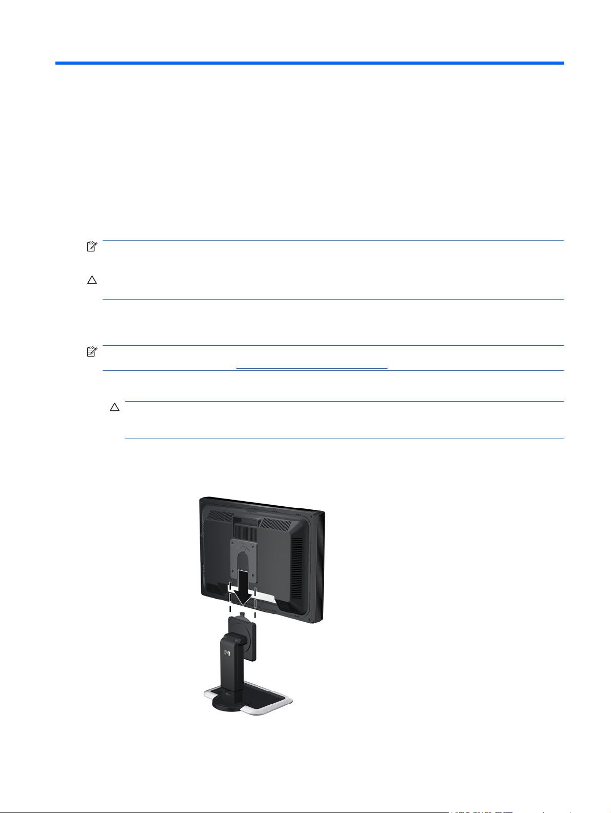
Installing the Monitor Pedestal Base
NOTE: Do not install the pedestal base if the monitor will be used on a wall, swing arm, or other
mounting fixture; instead see
Mounting the Monitor on page 16 in this chapter.
1. Using both hands, position the monitor over the pedestal base.
CAUTION: Do not touch the surface of the LCD panel. Pressure on the panel may cause non-
uniformity of color or disorientation of the liquid crystals. If this occurs the screen will not recover
to its normal condition.
2. Press down firmly on the monitor to lock the pedestal base in place. When the base locks, it will
make a clicking sound.
Figure 3-1 Inserting the Monitor into the Pedestal Base
Installing the Monitor Pedestal Base 7
Page 14
NOTE: Be sure the pedestal base is securely locked before continuing with the setup.
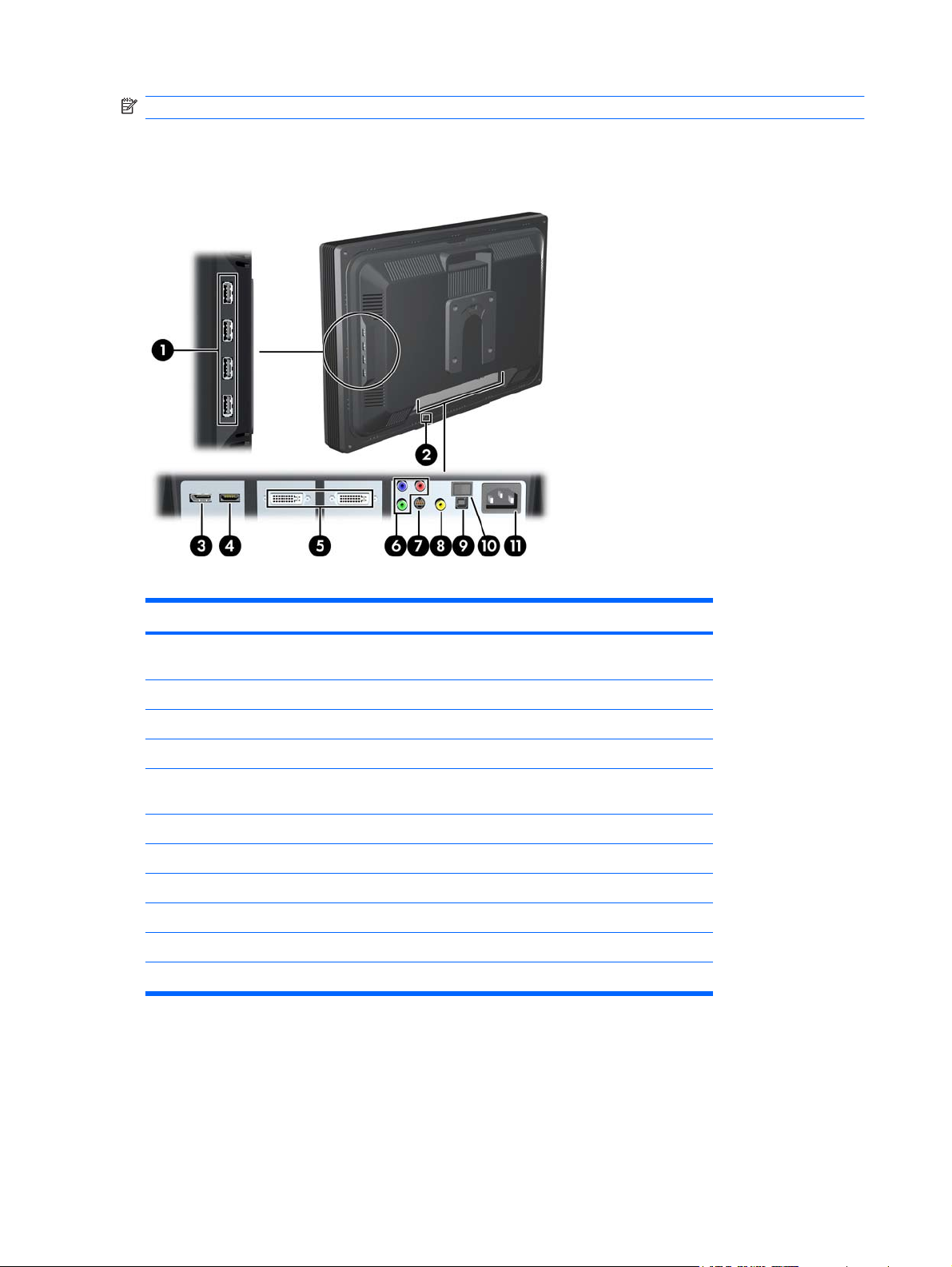
Rear Components
Figure 3-2 Rear Components
Table 3-1 HP LP2480zx Rear Components
Component Function
1 USB Downstream Connectors
(side panel)
2 Cable Lock Provision Provides slot for use with cable security locks.
3 DisplayPort Connector Connects the DisplayPort signal cable to the monitor.
4 HDMI Connector Connects the HDMI signal cable to the monitor.
5 DVI-I Connectors Connects the DVI-I to VGA signal cable or DVI-I to DVI-D
6 Component Connectors Connects Component signal cables to the monitor.
7 S-Video Connector Connects an S-Video signal cable to the monitor.
8 Composite Connector Connects a Composite signal cable to the monitor.
9 USB Upstream Connector Connects the monitor USB hub to a host USB port/hub.
10 Master Power Switch Turns off all power to the monitor.
11 AC Power Connector Connects the AC power cord to the monitor.
Connects optional USB devices to the monitor.
signal cable to the monitor.
8 Chapter 3 Setting Up the Monitor
Page 15
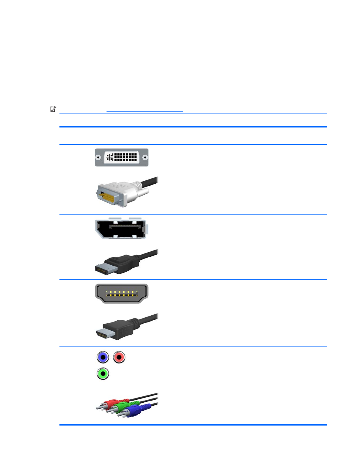
Selecting and Connecting the Signal Cables
The monitor features two DVI-I connectors capable of supporting either analog or digital input, one
DisplayPort connector, one HDMI connector, one set of Component connectors, one S-Video connector,
and one Composite connector.
The monitor will automatically select an active signal on the DVI, HDMI, and DisplayPort inputs. The
Component, S-Video, and Composite inputs must be selected manually. The inputs can be selected
through the On-Screen Display (OSD) feature by pressing the Input button on the front panel.
NOTE: Refer to Rear Components on page 8 for signal input connector locations.
Table 3-2 Signal Connectors and Cables
Input Monitor Connector and Cable
Plug
DVI-I The video mode supported by the DVI-I connectors are determined by the
DisplayPort Connect the DisplayPort cable provided to the DisplayPort connector on
HDMI Connect the HDMI cable provided to the HDMI connector on the monitor
Connection Description
video cable used.
For digital operation, use the DVI-I to DVI-D signal cable provided.
●
Connect the DVI-I to DVI-D signal cable to the DVI-I connector on
the monitor and the other end to the DVI-D connector on the
computer.
For analog operation, use the DVI-I to VGA signal cable provided.
●
Connect the DVI-I to VGA signal cable to a DVI-I connector on the
monitor and the other end to the VGA connector on the computer.
the monitor and the DisplayPort connector on the computer for digital
operation.
NOTE: The DisplayPort cable locks in place when it is connected. To
remove a DisplayPort cable, press the button on top of the cable end and
pull the cable end from the connector.
and the HDMI connector on the input device for digital operation.
Component
(Y Pb Pr)
Connect a set of Component cables to the Component connectors on the
monitor and the Component connectors on the input device for analog
operation. Cable set purchased separately.
Selecting and Connecting the Signal Cables 9
Page 16
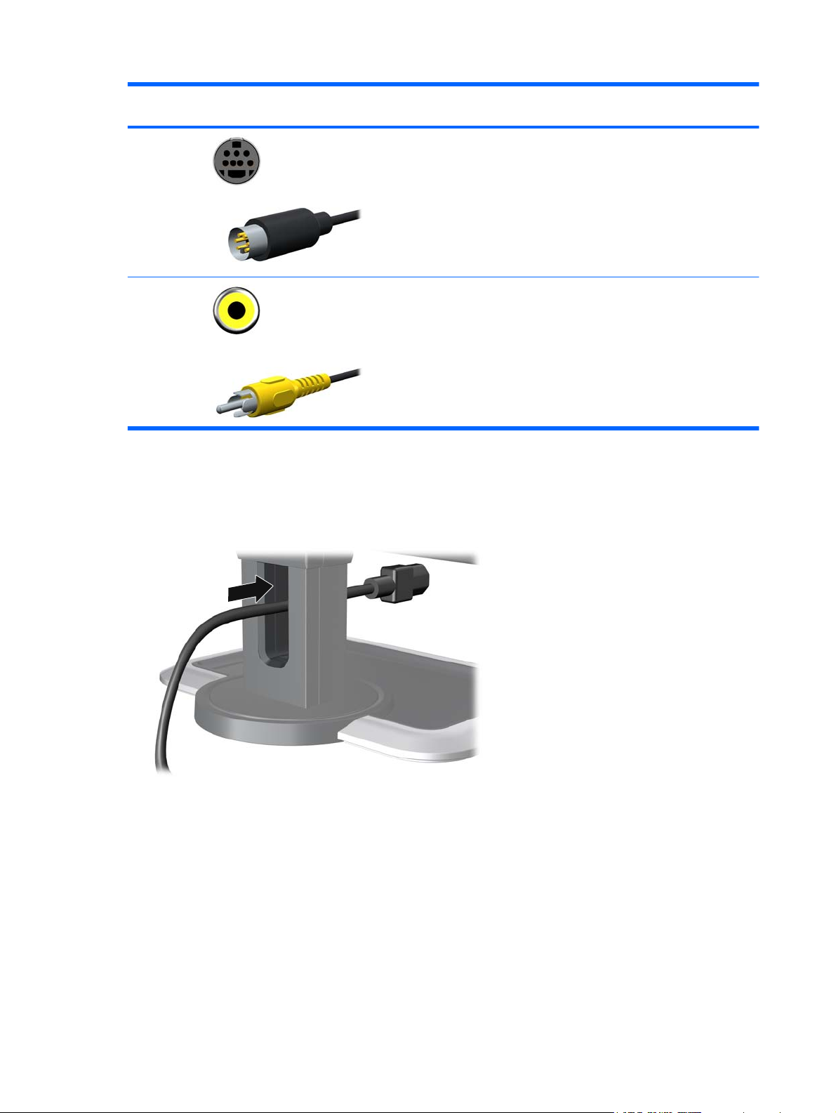
Table 3-2 Signal Connectors and Cables (continued)
Input Monitor Connector and Cable
Plug
S-Video Connect an S-Video cable to the S-Video connector on the monitor and
Composite Connect a Composite cable to the Composite connector on the monitor
Cable Management
Connection Description
the S-Video connector on the input device for analog operation. Cable
purchased separately.
and the Composite connector on the input device for analog operation.
Cable purchased separately.
Before connecting the cables, route them through the opening on the neck of the monitor's pedestal.
Figure 3-3 Using the Cable Management Feature
10 Chapter 3 Setting Up the Monitor
Page 17
Connecting the Monitor Power
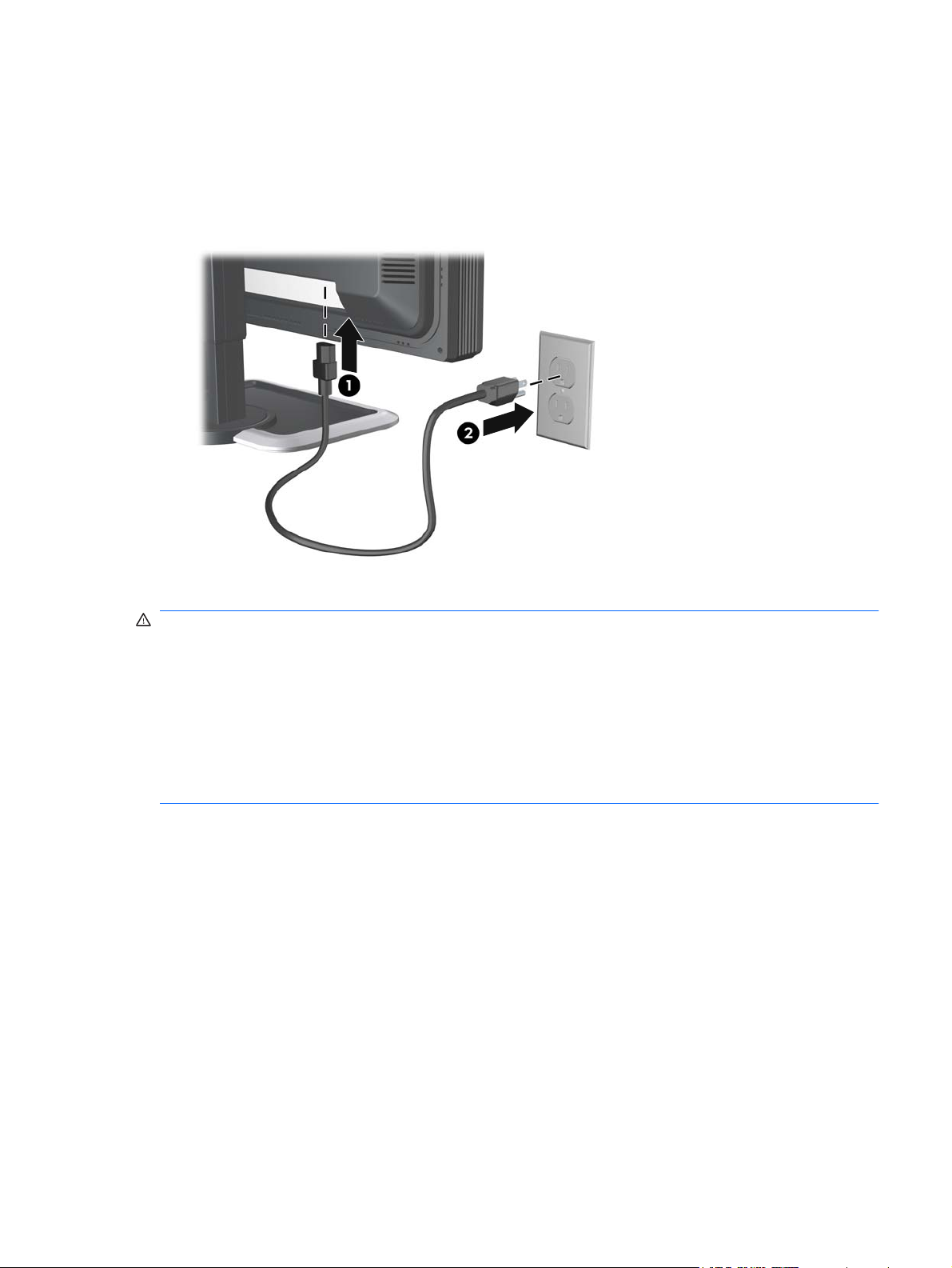
1. Place the monitor in a convenient, well-ventilated location near the computer.
2. Connect one end of the power cable to the AC power connector on the back of the monitor (1),
and the other end to an electrical wall outlet (2).
Figure 3-4 Connecting the Power Cable
WARNING! To reduce the risk of electric shock or damage to the equipment:
• Do not disable the power cord grounding plug. The grounding plug is an important safety feature.
• Plug the power cord into a grounded (earthed) electrical outlet that is easily accessible at all times.
• Disconnect power from the equipment by unplugging the power cord from the electrical outlet.
For your safety, do not place anything on power cords or cables. Arrange them so that no one may
accidentally step on or trip over them. Do not pull on a cord or cable. When unplugging from the electrical
outlet, grasp the cord by the plug.
Connecting the Monitor Power 11
Page 18
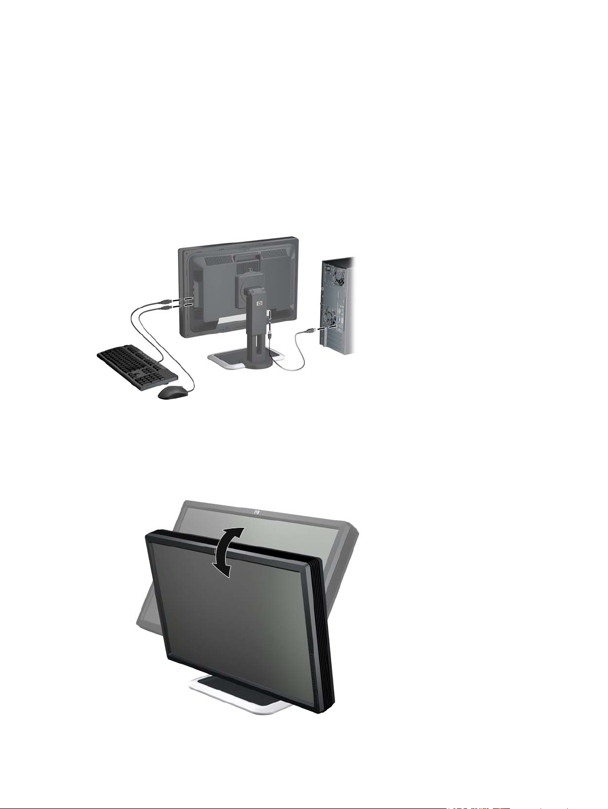
Connecting USB Devices
The monitor provides four USB connectors on the side panel that can be used to connect devices such
as a digital camera, USB keyboard, or USB mouse.
1. Connect one end of the USB hub cable to the USB connector on the rear panel of the computer,
and the other end to the upstream USB connector on the monitor.
2. Connect the USB devices to the USB downstream connectors on the side panel of the monitor.
Figure 3-5 Connecting USB Devices
Adjusting the Monitor
1. Tilt the monitor's panel forward or backward to set it to a comfortable eye level.
Figure 3-6 Tilting the Monitor
12 Chapter 3 Setting Up the Monitor
Page 19

2. Swivel the monitor to the left or right for the best viewing angle.
Figure 3-7 Swiveling the Monitor
3. Adjust the monitor's height so that it is parallel to your eye height for a comfortable viewing position.
WARNING! A lock-down/release button on the front of the column prevents the display panel
from sliding up when the monitor is lifted. If the display panel is locked in the lowest height position:
a. Make sure that the monitor is safely positioned on a stable surface.
b. Gently push down on the display panel.
c. While pushing down the display panel, press the lock-down/release button on the front of the
column.
d. Guide the display panel up to the desired height.
Figure 3-8 Adjusting the Height
Adjusting the Monitor 13
Page 20

4. Pivot the monitor clockwise from landscape to portrait orientation viewing to adapt to your
application.
CAUTION: USB cables that are connected to the monitor can be damaged if they come in contact
with the desk or table top surface when rotating the display panel to the portrait position. Ensure
that there is enough clearance for the USB cables as you rotate the monitor.
Be sure to remove any cables from the cable management opening before pivoting the monitor.
Figure 3-9 Pivoting the Monitor
NOTE: To view information on the screen in portrait mode, you will need to install the HP Display
Assistant software included on the software and documentation CD. The position of the OSD menu
can also be rotated to portrait mode. To rotate the OSD menu, press the Menu button on the
monitor's front panel, then select OSD Control > OSD Rotation.
CAUTION: Monitor display panel orientations of 180 and 270 degrees are not supported and may
result in damage to the monitor.
Turning on the Monitor
1. Press the power switch to turn on the computer.
2. Verify the master power switch on the rear of the monitor is in the on (I) position.
3. Press the power button on the front of the monitor.
CAUTION: Burn-in image damage may occur on monitors that display the same static image on
screen for a prolonged period of time.* To avoid burn-in image damage on the monitor screen, you
should always activate a screen saver application or turn off the monitor when it is not in use for a
prolonged period of time. Image retention is a condition that may occur on all LCD screens.
* A prolonged period of time is 12 consecutive hours of non-use.
NOTE: After turning on the monitor, a minimum 30 minute warm-up time is required for best
performance.
14 Chapter 3 Setting Up the Monitor
Page 21

Using the Accessory Rails
The monitor features accessory rails on the rear that may be used to mount optional devices, such as
the HP speaker bar, to the LCD monitor. Refer to the documentation included with the optional device
for detailed mounting instructions.
Figure 3-10 Using the Accessory Rails Feature
Removing the Monitor Pedestal Base
You can remove the monitor panel from the pedestal base to mount the panel on a wall, a swing arm,
or other mounting fixture.
This monitor has a Quick Release mechanism that allows you to easily remove and replace the monitor
panel to the pedestal base.
CAUTION: Before beginning to disassemble the monitor, be sure the monitor is turned off and the
power and signal cables are both disconnected. Also disconnect any USB cables that are connected to
the monitor.
1. Disconnect and remove the signal and power cables from the back of the monitor.
2. Slide the quick release latch (1) on the pedestal base to the side (either right or left).
Using the Accessory Rails 15
Page 22

3. Pull up on the monitor display panel (2) to remove it from the base.
Figure 3-11 Removing the Monitor from the Pedestal Base
Mounting the Monitor
The HP Quick Release can be removed from the pedestal base and installed on a mounting fixture. It
allows you to quickly and securely attach the monitor panel to the mounting fixture.
1. Remove the monitor panel from the pedestal base. Refer to
on page 15 in the previous section.
CAUTION: This monitor supports the VESA industry standard 100 mm mounting holes. To attach
a third-party mounting solution to the monitor, four 4 mm, 0.7 pitch, and 10 mm long screws are
required (not provided with the monitor). Longer screws must not be used because they may
damage the monitor. It is important to verify that the manufacturer’s mounting solution is compliant
with the VESA standard and is rated to support the weight of the monitor display panel. For best
performance, it is important to use the power and video cables provided with the monitor.
WARNING! To reduce the risk of personal injury or of damage to the equipment, check that the
wall-mounting fixture is adequately installed and secured before attaching the monitor. Refer to the
instructions supplied with the wall-mounting fixture and check that it is capable of supporting the
monitor.
Removing the Monitor Pedestal Base
16 Chapter 3 Setting Up the Monitor
Page 23

2. Remove the Quick Release from the pedestal base by removing the four screws.
Figure 3-12 Removing the HP Quick Release from the Pedestal Base
3. Mount the Quick Release to a swing arm or other mounting fixture using the four screws removed
from the Quick Release in the previous step.
Figure 3-13 Installing the Quick Release
CAUTION: The Quick Release can also be installed directly to a wall to mount the monitor panel.
It is designed to support a maximum of up to 10.9 kg (24 lbs). If you are mounting to a wall, HP
recommends that you consult with a qualified engineering, architectural, or construction
professional to determine the appropriate type and quantity of mounting fasteners required for your
application and to ensure that the mounting solution is properly installed to support applied loads.
Removing the Monitor Pedestal Base 17
Page 24

4. Insert the monitor panel into the Quick Release, and then press down firmly on the monitor to lock
it in place. When the Quick Release locks, it will make a clicking sound.
Figure 3-14 Inserting the Monitor Panel into the Quick Release
Locating the Rating Labels
The rating labels on the monitor provide the spare part number, product number, and serial number.
You may need these numbers when contacting HP about the monitor model. The rating labels are
located on the rear of the monitor display panel.
Figure 3-15 Locating the Rating Labels
18 Chapter 3 Setting Up the Monitor
Page 25

4 Operating the Monitor
Software and Utilities
The CD that comes with the monitor contains files you can install on the computer:
an .INF (Information) file
●
.ICM (Image Color Matching) files
●
auto-adjustment pattern utility
●
HP Display Assistant software
●
PDF Complete is supplied on this CD and can be installed from the menu.
NOTE: If the monitor does not include a CD, the .INF and .ICM files can be downloaded from the HP
monitors support Web site. See
Downloading from the Worldwide Web on page 20 in this chapter.
The Information File
The .INF file defines monitor resources used by Microsoft Windows operating systems to ensure monitor
compatibility with the computer’s graphics adapter.
This monitor is Microsoft Windows Plug and Play compatible and the monitor will work correctly without
installing the .INF file. Monitor Plug and Play compatibility requires that the computer’s graphic card is
VESA DDC2–compliant and that the monitor connects directly to the graphics card. Plug and Play does
not work through separate BNC type connectors or through distribution buffers/boxes.
The Image Color Matching File
The .ICM files are data files that are used in conjunction with graphics programs to provide consistent
color matching from monitor screen to printer, or from scanner to monitor screen. The .ICM file contains
a monitor color system profile. This file is activated from within graphics programs that support this
feature.
NOTE: The ICM color profile is written in accordance with the International Color Consortium (ICC)
Profile Format specification.
Software and Utilities 19
Page 26

Installing the .INF and .ICM Files
After you determine that you need to update, you can install the .INF and .ICM files from the CD or
download them.
Installing from the CD
To install the .INF and .ICM files on the computer from the CD:
1. Insert the CD in the computer CD-ROM drive. The CD menu is displayed.
2. View the Monitor Driver Software Readme file.
3. Select Install Monitor Driver Software.
4. Follow the on-screen instructions.
5. Ensure that the proper resolution and refresh rates appear in the Windows Display control panel.
NOTE: You may need to install the digitally signed monitor .INF and .ICM files manually from the CD
in the event of an installation error. Refer to the Monitor Driver Software Readme file on the CD.
Downloading from the Worldwide Web
To download the latest version of .INF and .ICM files from the HP monitors support Web site:
1. Refer to
2. Follow the links for the monitor to the support page and download page.
3. Ensure the system meets the requirements.
4. Download the software by following the instructions.
http://www.hp.com/support and select the country region.
20 Chapter 4 Operating the Monitor
Page 27

Using the Auto-Adjustment Function
You can optimize the screen performance for VGA (analog) input by using the - (Minus) button on the
monitor and the auto-adjustment pattern software utility on the CD provided.
Do not use this procedure if the monitor is using a DVI-D, HDMI, or DisplayPort input. If the monitor is
using a VGA (analog) input, this procedure can correct the following image quality conditions:
Fuzzy or unclear focus
●
Ghosting, streaking or shadowing effects
●
Faint vertical bars
●
Thin, horizontal scrolling lines
●
An off-center picture
●
To use the auto-adjustment feature:
1. Allow the monitor to warm up for 20 minutes before adjusting.
2. Press the - (minus) button on the monitor front panel.
You can also press the Menu button, then select Image Control > Auto Adjustment from
●
the OSD Main Menu. Refer to
If the result is not satisfactory, continue with the procedure.
●
Adjusting the Monitor Settings on page 23 in this chapter.
3. Insert the CD in the disc drive. The CD menu is displayed.
4. Select Open Auto-Adjustment Software. The setup test pattern is displayed.
5. Press the - (minus) button on the monitor front panel to produce a stable, centered image.
6. Press the ESC key or any other key on the keyboard to exit the test pattern.
Using the Auto-Adjustment Function 21
Page 28

Front Panel Controls
Table 4-1 Monitor Front Panel Controls
Control Function
1 Function Performs the function set in the OSD menu (OSD Control >
Function Control).
2 Input Selects the video input (DVI-1, DVI-2, HDMI, DisplayPort,
Component, S-Video, or Composite).
3 + (Plus) Navigates forward through the OSD menu and increases
adjustment levels.
4 – (Minus)
5 Menu/Select Opens, selects or exits the OSD menu.
6 Power LED Green = Fully powered.
7 Power Turns the monitor on or off.
Navigates backward through the OSD menu and
●
decreases adjustment levels.
When the OSD menu is inactive, activates the auto
●
adjustment feature to optimize the screen image.
Amber = Sleep mode.
Flashing Amber = Sleep Timer mode.
22 Chapter 4 Operating the Monitor
Page 29

Adjusting the Monitor Settings
The monitor settings can be adjusted from the On-Screen Display (OSD) menu or from the HP Display
Assistant software.
NOTE: If you are having a problem with the monitor settings, select the Factory Reset option in the
OSD menu to see if that solves the problem before adjusting other settings in the OSD menu. The
Factory Reset function returns all OSD menu settings and DDC/CI controls to the factory default settings,
except the language.
Using the On-Screen Display Menu
Use the On-Screen Display (OSD) to adjust the screen image based on your viewing preferences. To
access the OSD, do the following:
1. If the monitor is not already on, press the Power button to turn on the monitor.
2. To access the OSD Menu, press the Menu button on the monitor’s front panel.
3. To navigate through the OSD Menu, press the + (plus) button on the monitor’s front panel to scroll
down, or the – (minus) button to scroll up.
4. To select an item from the OSD Menu, use the + or – buttons to scroll to and highlight your selection,
then press the Menu button to select that function.
5. Adjust the item using the + or – buttons on the front panel to adjust the scale.
6. After adjusting the function, select Save and Return, or Cancel if you don’t want to save the setting,
then select Exit from the Main Menu.
NOTE: If the front panel buttons remain untouched for 40 seconds while displaying a menu, the OSD
will automatically “time out” and close, and all adjustments made in the OSD will be saved. The factory
default 40 second delay can be adjusted in the OSD to between 10 and 60 seconds.
Adjusting the Monitor Settings 23
Page 30
OSD Menu Selections
The following table lists the On-Screen Display (OSD) menu selections and their functional descriptions.
After changing an OSD menu item, and if the menu screen has these options, you may choose to:
Cancel—to return to the previous menu level.
●
Save and Return—to save all changes and return to the OSD Main Menu screen. This Save and
●
Return option is only active if you change a menu item.
Reset—to change back to the previous setting.
●
Table 4-2 OSD Menu
Icon Main Menu Submenu Description
Color Space Displays the Color Space presets.
Full Factory-calibrated preset with the full color gamut and native white
Adobe-RGB Factory calibrated preset for the Adobe-RGB standard.
SMPTE-C Factory calibrated preset for the SMPTE-C standard.
For each Color Space preset, the RGB primaries, WhitePoint,
Gamma, and Luminance are listed. Presets set up at the factory
can be reset to factory calibration. Presets set up by the user can
be reset to the last calibration.
point supported by the panel/backlight.
sRGB Factory calibrated preset for the sRGB standard.
Rec. 709 Factory calibrated preset for the Rec. 709 standard.
DCI-P3 Emulation Factory calibrated emulation preset for the DCI-P3 standard. Note
User-7 User-calibrated preset that must be set up before use.
Luminance/Brightness Adjusts the Luminance/Brightness level of the screen. The control
WhitePoint/Color Temp Adjust the WhitePoint/Color Temp level of the screen. The control
Primaries and Gamma
Information
Reset to Factory
Calibration
Reset to Last Calibration Returns Color Space preset to the last calibrated settings.
Image Control Adjusts the screen image.
Auto Adjustment Automatically adjusts the screen image.
Horizontal Position Adjusts the position of the screen image left and right.
the monitor’s color gamut does not fully enclose the DCI-P3 color
space.
range is 50 – 250 cd/m
range is 4000 – 12,000 K with a step size of 100.
Displays Primaries and Gamma information for the active Color
Space preset.
Returns Color Space preset to the factory calibrated settings.
2
with a step size of 1 cd/m2.
24 Chapter 4 Operating the Monitor
Vertical Position Adjusts the position of the screen image up and down.
Custom Scaling Selects the method on how displayed information on the monitor
will be formatted. Select:
Page 31

Table 4-2 OSD Menu (continued)
Icon Main Menu Submenu Description
Fill to Screen—image fills the entire screen and may look
●
distorted or elongated because of non-proportional scaling of
height and width
Fill to Aspect Ratio—image is sized to fit the screen and
●
maintains proportional image
One-to-one—disables video scaling, displays an image that
●
is smaller in size than the monitor’s capability and centers the
image on the screen in the active viewing area
Overscan—enables over-scanning of the image for HDMI,
●
Component, S-video, and Composite inputs
Crop Right Side—crops the video on the right side of the
●
image (enabled for the supported horizontal resolutions over
1920 pixels)
Crop Left Side—crops the video on the left side of the image
●
(enabled for the supported horizontal resolutions over 1920
pixels)
Crop Left and Right (Center)—crops the video on the left and
●
right sides in equal amounts and centers the image (enabled
for the supported horizontal resolutions over 1920 pixels)
Clock Minimizes any vertical bars or strips visible on the screen
background. Adjusting the Clock will also change the horizontal
screen image.
Clock Phase Adjusts the focus of the display. This adjustment allows you to
remove any horizontal noise and clear or sharpen the image of
characters.
Black Level Adjusts the black level or offset of the monitor. The factory default
value is 128 (no offset) and the range is 0 to 255.
OverDrive Disables or enables the overdrive feature. The factory default is
Enabled.
NOTE: OverDrive improves the response time of the panel for
watching motion video.
Hue Adjusts the Hue settings for the HDMI, Component, S-Video, and
Saturation Adjusts the Saturation settings for the HDMI, Component, S-
PIP Control Sets up PIP functionality.
PIP Mode Enables PIP mode (PIP or Side-by-Side).
Composite inputs.
Video, and Composite inputs.
NOTE: DVI-I, HDMI, and DisplayPort are supported for the main
window. Component, S-Video, and Composite are supported for
the secondary window.
PIP Position Sets the position of the PIP window on the screen. The choices
are top right, top left, bottom right, or bottom left.
Sub Picture Select Selects the input source for the PIP window. The choices are
Component, S-Video, or Composite video signal inputs.
Adjusting the Monitor Settings 25
Page 32

Table 4-2 OSD Menu (continued)
Icon Main Menu Submenu Description
Language Selects the language in which the OSD menu is displayed. The
factory default is English.
Management Selects the power management features of the monitor.
Power Saver Enables the power saving feature. Select:
On
●
Off
●
The factory default is On.
Power On Recall Restores power to the monitor following an unexpected removal
of power. Select:
On
●
Off
●
The factory default is On.
DDC/CI Support Allows the computer to control the OSD controls and calibrate the
Firmware Update
Support
Bezel Button LED Disables or enables the bezel button backlight LEDs.
Auto EDID Update Disables or enables the monitor’s automatic update of the DVI,
Sleep Timer Provides the timer adjustment menu options:
monitor. Set to:
On
●
Off
●
The factory default is On.
Enables or disables the monitor support of firmware updates. The
factory default is On.
NOTE: The Firmware Update Support is automatically disabled
when DDC/CI Support is disabled.
DisplayPort, and HDMI extended display identification data
(EDID) based on the selected Color Space preset. The EDID will
only be updated for the input selected for the primary window.
Set Current Time—sets the current time in hours and minutes
●
Set Sleep Time—sets the time you want to place the monitor
●
in sleep mode
Set On Time—sets the time you want the monitor to wake up
●
from sleep mode
OSD Control Provides a menu for adjusting the on-screen display (OSD)
26 Chapter 4 Operating the Monitor
Timer—sets the Sleep Timer feature On or Off. The default
●
setting is Off
Sleep Now—immediately sets the monitor to enter sleep
●
mode
controls.
Page 33

Table 4-2 OSD Menu (continued)
Icon Main Menu Submenu Description
Horizontal OSD Position Changes the viewing position of the OSD menu to the left or right
area of the screen. The factory default range is 50.
Vertical OSD Position Changes the viewing position of the OSD menu to the top or
Function Control Selects the operation of the front panel Function button. The
Monitor Status Message Disables or enables the Power-On Status Display and selects the
Warning Messages Enables or Disables OSD recommendation messages.
Calibration Limit Sets the limit (in backlight hours) for the calibration message. The
OSD Button Labels Disables or enables the front panel button label display on the
Mode Display Disables or enables the mode display information that is displayed
OSD Transparency Adjust to view the background information through the OSD.
OSD Timeout Sets the time duration in seconds that the OSD is visible after the
bottom area of the screen. The factory default range is 50.
options are Color Space, Brightness, Color Temp, Reset to Last,
Black Level, OverDrive, Custom Scale, Crop (L-C-R), and PIP
Control.
position the OSD message is displayed on the screen.
range is 0 to 5,000 hours. The factory default is 1000 hours. A
value of 0 disables the timer. The number of backlight hours since
the last calibration is also displayed.
screen.
on the bottom of the main menu.
last button is pressed. The range is 10 – 60 seconds. The factory
default is 40 seconds.
OSD Rotation Rotates the OSD menus and messages to support the monitor's
Pivot feature. The choices are 0 and 90 degrees.
Video Input
Control
DVI-1 Analog/Digital Selects DVI-I 1 as the primary video input. This input accepts
DVI-2 Analog/Digital Selects DVI-I 2 as the primary video input. This input accepts
HDMI Selects HDMI as the primary video input.
DisplayPort Selects DisplayPort as the primary video input.
Component Selects Component as the primary video input.
S-Video Selects S-Video as the primary video input.
Composite Selects Composite as the primary video input.
Input Auto-Switching Enables or disables the monitor automatically switching to an
Information Selects and displays important information about the monitor.
Current Settings Provides the current input video mode.
Provides a menu of the input options. The default input selection
is DVI-I 1.
either analog or digital signals.
either analog or digital signals.
active input if the current signal is inactive. The factory default is
Enabled.
Adjusting the Monitor Settings 27
Page 34

Table 4-2 OSD Menu (continued)
Icon Main Menu Submenu Description
Recommended Settings Provides the recommended resolution mode and refresh rate for
the monitor.
Last Calibration Displays the number of backlight hours since the last calibration.
Factory Reset Returns all OSD menu settings and DDC/CI controls to the factory
Exit Exits the OSD menu screen.
Optimizing Digital Conversion
Two controls in the on-screen display can be adjusted to improve image performance: Clock and Clock
Phase.
NOTE: The Clock and Clock Phase controls are adjustable only when using an analog input. These
controls are not adjustable for digital inputs.
Serial Number Reports the serial number of the monitor. The serial number is
needed if contacting HP technical support.
Version Reports the firmware version of the monitor.
Backlight hours Reports the total hours of backlight operation.
default settings, except the Language.
CAUTION: A Factory Reset will result in the loss of all user
control and Color Space settings. Use this feature only if other
attempts to troubleshoot the monitor have been unsuccessful.
The Clock must first be set correctly since the Clock Phase settings are dependent on the main Clock
setting. Use these controls only when the auto-adjustment function does not provide a satisfactory
image.
Clock—Increases/decreases the value to minimize any vertical bars or stripes visible on the screen
●
background.
Clock Phase—Increases/decreases the value to minimize video distortion or video jitter.
●
NOTE: When using the controls, you will obtain the best results by using the auto-adjustment pattern
software utility provided on the CD.
When adjusting the Clock and Clock Phase values, if the monitor images become distorted, continue
adjusting the values until the distortion disappears. To restore the factory settings, select Yes from the
Factory Reset menu in the on-screen display.
Using the HP Display Assistant Software
HP Display Assistant software, included on the software and documentation CD, is a software utility that
guides you through the tuning process with easy to understand instructions and background patterns
designed for each monitor control. It provides:
The ability to set up and select from multiple color space presets.
●
Software control of the monitor image and color settings to eliminate dependence on the monitor’s
●
front panel buttons and On-Screen Display (OSD) menu.
28 Chapter 4 Operating the Monitor
Page 35

Defined preset display settings for each individual user in a multi-user environment.
●
Asset Management and Power Management capabilities that include remote control for individual
●
or a group of displays on the domain from a centralized console application.
Theft deterrence to help reduce unauthorized relocation of the monitor.
●
NOTE: Refer to the HP Display Assistant software user guide for additional information about the
software.
Identifying Monitor Conditions
Special messages will appear on the monitor screen when identifying the following monitor conditions:
Input Signal Out of Range, Change Settings to 1920 x 1200 – 60Hz—Indicates the monitor does
●
not support the input signal because the resolution and/or refresh rate are set higher than the
monitor supports.
No Input Signal—Indicates the monitor is not receiving a video signal from the PC on the monitor
●
video input connector. Check to determine if the PC or input signal source is off or in the power
saving mode.
Auto Adjustment is in Progress—Indicates the auto-adjustment function is active.
●
Monitor Going to Sleep—Indicates the screen display is entering a sleep mode.
●
Check Video Cable—Indicates the video cable is not properly connected to the computer.
●
OSD Lockout—The OSD can be enabled or disabled by pressing and holding the Menu button
●
on the front panel for 10 seconds. If the OSD is locked, the warning message OSD Lockout
displays for ten seconds.
If the OSD is locked, press and hold the Menu button for 10 seconds to unlock the OSD.
◦
If the OSD is unlocked, press and hold the Menu button for 10 seconds to lock the OSD.
◦
Power Button Lockout—Indicates the power button is locked. If the power button is locked, the
●
warning message Power Button Lockout displays.
If the power button is locked, press and hold the power button for 10 seconds to unlock the
◦
power button function.
If the power button is unlocked, press and hold the power button for 10 seconds to lock out
◦
the power button function.
Recommend Recalibration for Best Color Performance—Indicates the calibration limit has
●
been reached or a change has been made to one of the color controls (RGB primaries, Gamma,
Luminance, WhitePoint, or Black Level)
Color Settings have Changed, Recommend you Update the Monitor Color Profile—Indicates
●
the need to change the color profile for the OS when the active color space preset or settings have
been changed.
Recommend Minimum 30 Minute Warm-up for Best Color Performance—Indicates a minimum
●
30 minute warm-up period is recommended after the monitor is first powered on or comes out of
Sleep mode (when not displaying video for 30 minutes or more).
Identifying Monitor Conditions 29
Page 36

Scanning Inputs. Please Wait—Indicates the monitor is in the process of scanning the DVI
●
(analog and digital), DisplayPort, and HDMI inputs.
Color Gamut Remapping Enabled—Indicates the color gamut remapping has been enabled
●
because the monitor video input or video signal changed from YUV to an RGB signal.
Color Gamut Remapping Disabled—Indicates the color gamut remapping has been disabled
●
because the monitor video input or video signal changed from RGB to a YUV signal.
Sleep Timer Mode
The Sleep Timer mode is an energy-saving feature that enables you to set a time for the monitor to
power on and off at the same time every day. This also extends the life of the backlight bulbs in the
monitor. The Sleep Timer has five settings:
Set Current Time
●
Set Sleep Time
●
Set On Time
●
Timer: On/Off
●
Sleep Now
●
To set the timer:
1. Press the Menu button on the monitor front panel to display the OSD Menu.
2. Scroll down and highlight Management.
3. Press the Menu button to select Management.
4. Scroll down and highlight and select Sleep Timer > Set Current Time.
NOTE: You must set the current local time before you reset the time for Sleep Time or On
Time. Note that the time is displayed in a 24–hour clock format. For example, 1:15 p.m. is displayed
as 13 hours 15 minutes.
5. Press the Menu button once to enter the adjustment mode for hours.
6. Press the - (Minus) or + (Plus) button to adjust the hour.
7. Press the Menu button again to enter the time for minutes.
8. Press the - (Minus) or + (Plus) button to adjust the minutes.
9. Press the Menu button to lock in the time chosen.
10. After setting the current time, the highlight automatically skips to Set Sleep Time hours. Repeat
steps 6 through 9 to set Sleep Time.
11. If you do not want to set Sleep Time, press the Menu button twice, then select Save and
Return to exit the menu.
12. After setting Sleep Time, the highlight automatically skips to Set On Time hours. Repeat steps 6
through 9 to set On Time.
30 Chapter 4 Operating the Monitor
Page 37

13. Set the Timer mode to On to activate the Sleep Timer settings.
14. When you are finished, select Save and Return to exit the menu.
The fifth selection, Sleep Now, turns the monitor backlights off immediately and stays in sleep mode
until the next On Time activates or a monitor button is pressed.
Recommended Options
For Microsoft Windows and Macintosh users, HP recommends purchasing the HP/X-Rite color
calibration kit. The calibration kit is required to set up new color space presets and calibrate the monitor
to maintain the color performance. For more information on the color calibration kit, refer to
http://www.hp.com.
For best color performance, HP recommends the monitor be used in an environment with minimal
ambient light. If the monitor is used in a typical office environment with bright overhead lights, HP
recommends using a monitor hood to minimize ambient light. For more information on the monitor hood,
refer to
http://www.hp.com.
Recommended Options 31
Page 38

A Advanced Color Management Features
and Usage
The HP LP2480zx monitor provides several advanced features that make it particularly well-suited to
color-critical applications, such as professional computer graphics development, video production, and
similar uses. These include:
True 10-bit drivers in the LCD panel itself, and the ability to support true 10 bits/color (30 bits/pixel)
●
video through the DisplayPort 1.1 and HDMI 1.3 inputs.
An LED backlight unit (instead of the usual cold-cathode fluorescent, or CCFL type) with
●
independent control of the red, green, and blue channels. This permits white point control using
the backlight, and a very wide range of white level (peak luminance) settings.
The LED backlight, coupled with specially-selected color filters in the LCD, provides a very wide
●
gamut (133% of the 1953 NTSC gamut area, as expressed in the CIE 1976 u′v′ space) for this
monitor. As this gamut encloses a number of standard output device gamuts, such as Adobe RGB
and sRGB/Rec. 709, this enables accurate emulation of these standards by means of gamutadaptation capabilities built into the monitor.
NOTE: In the earlier 1931 CIE xy space, the gamut area of the LP2480zx is 110% that of the
1953 NTSC gamut.
The monitor “front-end” electronics provides support for the gamut adaptation mentioned above,
●
including numerous factory-adjusted color space presets, which permit the user to quickly set up
the monitor to accurately emulate these standard output device specifications. The factorycalibrated presets include Adobe RGB, sRGB, ITU-R Rec. BT-709, SMPTE-C, and the Digital
Cinema Initiative reference projector (informally known as DCI-P3, also SMPTE-431-2) output
device spaces, in addition to space for a user-adjustable preset.
The user preset permits the setup of a custom color space emulation, with full control over the
●
desired RGB primaries, white point, white luminance, and gamma (display transfer function).
This Appendix will detail the operation and usage of these features provided on the LP2480zx monitor.
32 Appendix A Advanced Color Management Features and Usage
Page 39

Color Gamut and Color Space Coverage
The LP2480zx monitor uses an LED-backlit LCD module that provides an extremely wide color gamut.
This gamut was chosen to enclose a number of color spaces as defined by various standard output
device specifications, which (along with other color-management features in this product’s electronics)
permits the monitor to accurately emulate display devices conforming to these standards. The nominal
native primary set, white point, and gamma of the LP2480zx, and those of the various supported
standards, are provided in the table below:
Table A-1 Supported Color Gamut and Color Space
Full Adobe RGB SMPTE-C ITU-Rec. BT.
709
White point:
Color temp
(CCT)
Red x 0.690 0.640 0.630 0.640 0.640 0.680
u' 0.529 0.451 0.433 0.451 0.451 0.496
v' 0.517 0.523 0.526 0.523 0.523 0.526
Green x 0.205 0.210 0.310 0.300 0.300 0.265
y 0.715 0.710 0.595 0.600 0.600 0.690
u' 0.073 0.076 0.130 0.125 0.125 0.099
6500K 6500K 6500K 6500K 6500K ~6300K
x 0.313 0.313 0.313 0.313 0.313 0.314
y 0.329 0.329 0.329 0.329 0.329 0.351
u' 0.198 0.198 0.198 0.198 0.198 0.191
v' 0.468 0.468 0.468 0.468 0.468 0.480
y 0.300 0.330 0.340 0.330 0.330 0.320
sRGB DCI-P3
(SMPTE-431
†
-2)
v' 0.576 0.576 0.563 0.563 0.563 0.578
Blue x 0.150 0.150 0.155 0.150 0.150 0.150
y 0.045 0.060 0.070 0.060 0.060 0.060
u' 0.185 0.175 0.176 0.175 0.175 0.175
v' 0.125 0.158 0.178 0.158 0.158 0.158
Gamma 2.2 2.2 2.2 ~2.2* ~2.2* 2.6
* The display response specified by the sRGB and ITU-R Rec. BT.709 standards cannot be accurately described by a simple
gamma value; see
† The Digital Cinema/SMPTE-431-2 reference projector gamut is not fully enclosed by the LP2480zx’s native gamut; when set
to the DCI preset, the monitor will provide as accurate an emulation of this space as possible within its available gamut. The
difference is primarily along the red-green edge of the DCI gamut, as the DCI red and green primaries are slightly outside the
LP2480zx gamut. See the diagram below.
Transfer Function (Gamma) on page 39 in this appendix for details.
Color Gamut and Color Space Coverage 33
Page 40

As plotted within the 1976 CIE u’v’ color space, these gamuts are shown below:
Figure A-1 Color Space Diagram
Color Space Emulation
As noted earlier, the LP2480zx has the capability of emulating a display that conforms to a number of
standard output device specifications, such as sRGB, Adobe RGB, and et cetera. This emulation
includes matching the specified primaries, transfer function (gamma), white point, and, where
appropriate, white level (luminance) of the target specification. Preset color spaces are provided as
described earlier, and in addition, the user may program custom spaces as desired. Full custom color
space programming involves the selection of primaries, white point, gamma value, and et cetera, which
may be accomplished using the optional HP/X-Rite calibration tool. However, the display luminance
(brightness) and white point may be adjusted using the on-screen display (OSD) or HP Display Assistant
software.
The following sections describe the theory behind this emulation, the hardware provided to support it in
the LP2480zx, and information on its usage.
Theory of Operation
In general, most display devices such as CRT- or LCD-based monitors, may be mathematically modeled
as comprising two functions: first, a mapping of the input values (which we will assume for this discussion
are in the form of “RGB” codes, that is, the relative values of red, green, and blue levels for each pixel
in the image) to the intensity of light output by the device for each (this is the display’s transfer function,
sometimes referred to as the gamma, for each of the three channels). This now “gamma adjusted” data
must also be mapped to the specific primary colors and intensities provided by the display device for
34 Appendix A Advanced Color Management Features and Usage
Page 41

each of the three channels (that is, exactly what will be output, in terms of light, for the given values of
red, green, and blue). This may be expressed by the following diagram:
Figure A-2 Model of Standard Display Device
Here, the input RGB values are first modified by the appropriate transfer function (γR, γG, or γB); this
operation may be viewed as being performed by three look-up tables (LUTs) of the appropriate width
and depth. The modified RGB values (R′, G′, and B′) are then mapped to the resulting output light levels
of the correct intensity and color. This may be viewed as a matrix multiplication operation (A) involving
the R′G′B′ values and the appropriate XYZ tristimulus values for the specific display device primaries,
luminance, and white point in question:
Figure A-3 Matrix Multiplication of Input Values
In essence, the R′, G′, and B′ values may be seen as “gain controls” on three light sources whose peak
outputs are described as (X
R,YR,ZR
), (XG,YG,ZG), and (XB,YB,ZB). The display device itself – in this case,
the LCD module used in the LP2480zx monitor – of course has its own native characteristics which may
be modeled as described above. The problem of emulating a different (presumably, standard) output
device characteristic is then one of adding a “transform” block (T, in the diagram below) which will modify
this native characteristic such that the overall system emulates the desired performance. In terms of the
above diagram, if the combination of γ
function of the transform block T to correct the native display characteristics (γ
and AS represent the desired standard characteristic, it is the
S
and AD) such that the
D
output (TD) of this system matches that of the standard device, for the same input values:
Color Space Emulation 35
Page 42

Figure A-4 Correcting Native Display Characteristics
It can be shown that the required transform (T) may be implemented as a pair of appropriately-sized
look-up tables (LUTs), on either side of a 3 x 3 matrix multiplication. The LUT preceding the matrix
multiplication (the “pre-LUT”) implements the desired standard transfer function or gamma response
curve, such that input values are correctly mapped per that standard into a “linear light” space. The
required matrix for the color remapping (which is referred to as R) is a combination of the matrix that
transforms R′G′B′ to X′Y′Z′ values under the target standard (A
matrix for the existing display device (A
-1
R = A
A
D
S
). In other words,
D
), and the inverse of the corresponding
S
This stage must then be followed by a second look-up table (the “post-LUT”), which linearizes the
existing display device; specifically, it contains the inverse of the display’s transfer functions γ
D(R,G,B)
.
The complete transform block (plus the LCD module) as implemented in the LP2480zx monitor is then:
Figure A-5 Color Space Conversion Hardware in the LP2480zx
36 Appendix A Advanced Color Management Features and Usage
Page 43

Note that since the look-up tables for the three channels (R, G, and B) are independent, differences in
the display device’s transfer function across these three, along with any minor errors in the display white
point, may be “nulled out” using the look-up tables, in addition to the operations required for the color
space emulation as described above. In the LP2480zx, these functional blocks are implemented as part
of the “front end” electronics, in addition to the usual scaler/controller functions of a standard monitor.
Due to the limitations imposed by the components used in the LP2480zx front end, full color space
emulation functionality is not available on the analog composite, component, or S-Video inputs*; it is,
however, fully supported when using the DVI-I (both analog and digital sections), HDMI, and DisplayPort
inputs IF the input video is provided using RGB encoding. Color space emulation is not provided on any
input for video using YUV/YC
encoding. The complete matrix of feature support for the various inputs
BCR
and signal encodings is provided in the table on the following page.
NOTE: * These inputs connect between the pre-LUTs and the 3x3 matrix multiplier; therefore, re-
mapping of the input values per the desired output device transfer function is not possible.
Selection of the desired standard color space, or selection of a user-defined custom color space setting,
may be achieved through the on-screen display (OSD) menus, the HP Display Assistant software, or
the optional HP/X-Rite calibration software. These provide the correct programming of the color
management hardware described above as needed for the desired color space characteristics.
NOTE: Refer to the monitor’s DDC/CI and USB communication specification for more details.
Summary of Color Space Selection Availability
As noted, the selection of output device color space presets and the resulting emulation of the desired
display characteristics, is not available for all LP2480zx inputs or all color encodings. Basically, this
functionality is available only when a progressive-scanned RGB input is provided by the video source.
YUV (which is considered here as including YC
, et cetera) encoding cannot be used, nor can color
BCR
space emulation be supported for interlaced video (as the LP2480zx must convert any interlaced video
to YUV, if not in this form already, in order for the built-in de-interlacing to operate correctly). When
support for the standard or user-defined color space presets cannot be provided, these options will be
“grayed out” on the OSD, and adjustments for image Hue and Saturation will be provided instead.
Table A-2 Supported Signal Inputs and Color Space Matrix
Input used Color encoding Scan format Result
DVI RGB (YUV not supported on
these inputs)
HDMI or DisplayPort RGB Progressive Color Space presets: enabled
YUV Either Color Space presets: disabled
Progressive Color Space presets: enabled
Hue/Saturation controls:
disabled
Hue/Saturation controls:
disabled
Interlaced Color Space presets: disabled
Hue/Saturation controls:
enabled
Hue/Saturation controls:
enabled
Color Space Emulation 37
Page 44

Table A-2 Supported Signal Inputs and Color Space Matrix (continued)
Input used Color encoding Scan format Result
Component, CVBS, S-Video YUV (RGB not supported) Either Color Space presets: disabled
10 bits/color LCD Module
As noted earlier, the LCD module in the LP2480zx monitor provides a 10 bits/color (30 bits/pixel) input,
with true 10-bit drivers within the LCD itself. This means that each primary (red, green, and blue) may
be controlled over 1,024 steps (input codes 0 to 1023) from the black level to the white (peak luminance
for that color). This results in over 1.07 billion separate colors available within the display’s gamut, versus
approximately 16.7 million for a conventional 8 bits/color display.
This increase in dynamic range is required for the accurate display of color within the wide gamut
provided by the LP2480zx’s LCD, and especially for achieving the necessary degree of color accuracy
within the more restricted gamuts that this monitor is capable of providing when emulating various
standard output devices. Increasing a display’s color gamut – the area covered by the display when the
primaries are plotted on a standard chromaticity diagram – would result in a greater difference between
adjacent colors if the degree of control (bits per color) for each primary were not also increased.
Increasing the bit depth of the display drivers achieves this without the possibility of undesirable image
artifacts which may result from temporal or spatial dithering as may sometimes be used with an LCD of
lower inherent accuracy. (The LP2480zx’s “front-end” electronics are also, however, capable of
providing temporal dithering, if needed, to increase the delivered accuracy beyond the 10 bits/color level.
By default, this is used only between the pre-LUT and the 3x3 matrix multiplier stage; temporal dithering
is possible but normally disabled at the 30-bit connection between the post-LUT and the LCD module
itself.)
Hue/Saturation controls:
enabled
With most video sources (which typically provide video information at the standard 8 bits/color or 24
bits/pixel), and across all of the LP2480zx’s various inputs, the increased accuracy of the LP2480zx
LCD module is used to provide more accurate color within the selected standard color space. However,
30-bit sources may also be directly supported using the DisplayPort 1.1 and HDMI 1.3 inputs only. This
will be of greatest benefit when the LP2480zx is used in the wider-gamut modes (such as Full, Adobe
RGB, DCI).
LED Backlight Unit
As noted earlier, the LP2480zx monitor employs a backlight consisting of an array of red, green, and
blue light-emitting diodes (LEDs) rather than the more typical cold-cathode fluorescent lamps (CCFLs)
on most LCD monitors. This provides several significant advantages, in addition to the obvious benefit
of a wider color gamut (that is, more saturated primaries) than can currently be achieved using CCFLs.
In the LP2480zx, the red, green, and blue LED arrays are controlled both collectively and separately by
a dedicated backlight controller, which permit both very accurate setting of the display luminance as
well as control of the white point of the unit. Color sensors in the backlight unit feed color information
back to the controller constantly, permitting an accurate white point to be maintained.
Compared with CCFLs, which have only a limited range of brightness control available and a fixed
emission spectrum, the LED backlight used here provides a very wide range of both brightness and
color control. The white point may be adjusted over a range corresponding to a correlated color
temperature (CCT) of 4,000K to 12,000K, including support for all standard white points with CCTs within
this range. In addition, the white luminance may be adjusted from a maximum of approximately 250 cd/
2
down to 50 cd/m2, making the LP2480zx suitable for use in low-light environments; at the lower
m
38 Appendix A Advanced Color Management Features and Usage
Page 45

brightness settings, both its white luminance and black level compare favorably with those of traditional
CRT displays. (At the low end of this range, the monitor’s black level will typically be approximately 0.05
2
.)
cd/m
As with several other parameters set in the color space presets, the programming of the backlight
controller is managed either through the LP2480zx’s on-screen display (OSD), or by using the HP
Display Assistant software.
Transfer Function (Gamma)
As noted briefly in the previous section on Color Space Emulation on page 34 in this Appendix, display
devices typically impose a non-linear transfer function on the input video data, in terms of how the
intensity of the light output by the device varies versus these inputs. This is often referred to as the
display’s “gamma” response characteristic, as one simple model for this behavior is a power-function
curve (in which the exponent is typically represented by the Greek letter gamma, γ) as follows:
Figure A-6 Gamma Curve Response Characteristic
This model, with a “gamma” value of about 2.2 – 2.5, describes the actual response of a standard CRT
display fairly well,* and so was assumed for years to be the typical response curve of an electronic
display device. As it turns out, encoding image information under the assumption of an output device
response of this nature has other advantages, and so it remains very common for standard output device
specifications to require a transfer function or response curve which is of this general nature. The most
common modification to this simple model as seen in many current output device or image encoding
standards is the addition of a linear region at the lower end of the response curve, as shown in the
following diagram. This linear region avoids problems, which otherwise would result from applying the
inverse of the response curve (in image encoding), as otherwise the slope of the curve would be
changing very rapidly in the low-luminance regions of the image.
NOTE: * The biggest shortcoming of the simple gamma curve model as given, with respect to CRT
displays, is that the black level of the input signal (assumed to be zero) does not generally result in
exactly zero luminance for a properly-adjusted CRT. This requires the addition of an offset term into the
model. However, the basic model as shown here remains an adequate description for most non-critical
work.
Transfer Function (Gamma) 39
Page 46

Figure A-7 Low Linear Region Response Curve
A generalized model for the display response curve accommodating the addition of a linear section as
shown above thus requires the specification of four parameters in addition to the “gamma” exponent
value:
For input values (I) ≤ A
Y = I/A
1
:
0
For input values (I) > A0′
Y = [(I + A
)/(1 + A3)]
2
γ
The response of the LP2480zx is automatically set to the correct standard as part of the color-space
selection, using either the on-screen display (OSD) or using the HP Display Assistant software, or using
the optional HP/X-Rite color calibration tools. Independently programming a custom response (as in the
case of the user-defined custom color space preset) requires use of the HP/X-Rite calibration tools.
Using the software provided with this calibration product, the display response may be programmed
using the four-value-plus-gamma model described above.
Several of the standard color space specifications supported by the LP2480zx require the use of the
“four-value” model, as they include a linear section in the response curve as described above. Of course,
even the simple “gamma-only” model may be accommodated within the four-value model, by setting
, A2, and A3 parameters to zero, and A1 to a value of 1.0. The values used to describe the response
the A
0
for the standard color spaces or output device specifications supported by the LP2480zx are listed in
the table below.
Table A-3 Response Curve Constants for Various Color Spaces
Color space A
0
A
1
A
2
A
3
gamma (γ)
sRGB 0.04045 12.92 0.055 0.055 2.4
ITU-R BT.709 0.081 4.50 0.099 0.099 2.22222
SMPTE-C 0.081 4.50 0.099 0.099 2.22222
Adobe® RGB 0 1 0 0 2.19922
DCI-P301002.6
40 Appendix A Advanced Color Management Features and Usage
Page 47

Table A-3 Response Curve Constants for Various Color Spaces (continued)
Color space A
Full 0 1 0 0 2.2*
* Note that in “full gamut” mode, the color space emulation capabilities of the LP2480zx monitor are used to correct any
deviations in the LCD’s native performance from its nominal specified values. The color gamut, white point, and response curve
seen in this mode are therefore those of the LCD panel itself, but corrected to their nominal values as accurately as possible.
0
A
1
A
2
A
3
gamma (γ)
References:
Adobe® RGB (1998) Color Image Encoding, Version 2005-05, May 2005, Adobe Systems, Inc.
●
http://www.adobe.com/digitalimag/pdfs/AdobeRGB1998.pdf
Digital Cinema System Specification, Vers. 1.1, April 12, 2007 Digital Cinema Initiatives, LLC
●
http://www.dcimovies.com
IEC 61966-2-1:1999 Colour Measurement and Management in Multimedia Systems and
●
Equipment – Part 2-1: Default RGB Colour Space – sRGB, International Electrotechnical
Commission, TC 100
http://tc100.iec.ch/index_tc100.html
ITU Recommendation BT. 709: Parameter values for the HDTV standards for production and
●
international programme exchange, April 2002, International Telecommunications Union
http://www.itu.int/net/home/index.aspx
SMPTE Recommended Practice 145-2005, SMPTE-C Color Monitor Colorimetry
●
SMPTE Standard 431-2, Reference Projector and Environment for Display of DCDM in Review
●
Rooms and Theaters, Society of Motion Picture and Television Engineers
http://www.smpte.org
Transfer Function (Gamma) 41
Page 48

B Troubleshooting
Solving Common Problems
The following table lists possible problems, the possible cause of each problem, and the recommended
solutions.
Problem Possible Cause Solution
Screen is blank. Power cord is disconnected. Connect the power cord.
Power button on front panel of the
monitor is turned off.
Video cable is improperly
connected.
Screen blanking is active. Press any key on the keyboard or move the mouse to
Monitor will not turn on. Master power switch on rear panel
Image appears blurred,
indistinct, or too dark.
Image is not centered Position may need adjustment. Press the Menu button to access the OSD menu. Select
Check Video Cable is
displayed on screen.
Input Signal Out of Range,
Change Settings to 1920 x
1200 – 60Hz is displayed on
screen.
of the monitor is turned Off.
Brightness is too low. Press the – (minus) button on the front panel. If this does
Monitor video cable is
disconnected.
Video resolution and/or refresh rate
are set higher than what the monitor
supports.
Press the front panel power button.
NOTE: If pressing the power button has no effect, press
and hold the power button for 10 seconds to disable the
power button lockout feature.
Connect the video cable properly. Refer to Setting Up the
Monitor on page 7 for more information.
inactivate the screen blanking utility.
Turn the master power switch to On.
not correct the image, press the Menu button to open the
OSD Menu, and adjust the brightness scale as needed.
Image Control/Horizontal Position or Vertical Position to
adjust the horizontal or vertical position of the image.
Connect the appropriate video signal cable between the
computer and monitor. Be sure that the computer power is
off while connecting the video cable.
Restart the computer and enter Safe Mode. Change the
settings to a supported setting (see
Display Resolutions on page 46). Restart the computer
so that the new settings take effect.
Recognizing Preset
The monitor is off but it did
not seem to enter into a lowpower sleep mode.
OSD Lockout is displayed. The monitor's OSD Lockout
Power Button Lockout is
displayed.
42 Appendix B Troubleshooting
The monitor's power saving control
is disabled.
function is enabled.
The monitor's Power Button
Lockout function is enabled.
Check the monitor's OSD menu setting for power saving
enable/disable controls. The control should be set to
enable to allow the monitor to enter into low-power modes.
Press and hold the Menu button for 10 seconds to disable
the OSD Lockout function.
Press and hold the power button for 10 seconds to unlock
the power button function.
Page 49

Using the Worldwide Web
For the online access to technical support information, self-solve tools, online assistance, community
forums of IT experts, broad mutlivendor knowledge base, monitoring and diagnostic tools, go to
http://www.hp.com/support
Preparing to Call Technical Support
If you cannot solve a problem using the trouble shooting tips in this section, you may need to call
technical support. Have the following information available when you call:
The monitor
●
Monitor model number
●
Serial number for the monitor
●
Purchase date on invoice
●
Conditions under which the problem occurred
●
Error messages received
●
Hardware configuration
●
Video card
◦
Type of computer
◦
Cable input used (for example, HDMI, VGA, DVI, or DisplayPort)
◦
Calibration system used
●
Hardware and software you are using
●
Using the Worldwide Web 43
Page 50

C Technical Specifications
NOTE: All performance specifications are provided by the component manufacturers. Performance
specifications represent the highest specification of all HP's component manufacturers' typical level
specifications for performance and actual performance may vary either higher or lower.
HP LP2480zx Model
Table C-1 HP LP2480zx Model Specifications
Display
Type
Viewable Image Size 61 cm diagonal 24–inch diagonal
Tilt Adjustment -5 to 35°
Swivel Adjustment -45 to 45°
Height Adjustment 100 mm range 3.94–inch range
Pivot Clockwise
Maximum Weight (Unpacked) 12.5 kg 27.5 lbs.
Dimensions (include base)
Height
Depth
Width
Optimum Graphic Resolution 1920 × 1200 (60Hz) analog input
Text Mode 720 × 400
Dot Pitch 0.270 (H) × 0.270 (W) mm
61 cm
TFT LCD
42.5 cm
25.4 cm
56.5 cm
1920 × 1200 (60Hz) digital input
24 inches
16.7 inches
10.0 inches
22.2 inches
Horizontal Frequency 24 to 76 kHz
Vertical Refresh Rate 47 to 61 Hz
Environmental Requirements Temperature
Operating Temperature
Storage Temperature
Relative Humidity 20 to 80%
44 Appendix C Technical Specifications
5 to 35° C
-20 to +60° C
41 to 95° F
-4 to 140° F
Page 51

Table C-1 HP LP2480zx Model Specifications (continued)
Power Source 90 — 265 VAC, 45–63 Hz
Altitude:
Operating
Storage
Power Consumption (maximum) <90 watts
Input Terminal Two DVI-I connectors with DVI-I to DVI-D and DVI-
0 to 3657.6 m
0 to 12192 m
I to VGA cables included; DisplayPort connector
with cable included; HDMI connector with cable
included; Component connectors; S-Video
connector; Composite connector
0 to 12,000 feet
0 to 40,000 feet
HP LP2480zx Model 45
Page 52

Recognizing Preset Display Resolutions
The display resolutions listed below are the most commonly used modes and are set as factory defaults.
This monitor automatically recognizes these preset modes and they will appear properly sized and
centered on the screen.
Table C-2 LP2480zx Model Factory Preset Display Modes
Preset Pixel Format Horz Freq (kHz) Horz
Polarity
1 640 × 480 31.47 – 59.94 – 25.175 VGA
2 640 × 480 37.50 – 75.00 – 31.500 VGA
3 720 × 400 31.47 – 70.08 + 28.321 VGA
4 800 × 600 37.88 + 60.32 + 40.000 VESA
5 1024 × 768 48.36 – 60.00 – 65.000 VESA
6 1152 × 720 44.86 – 60.0o + 66.750 CVT 0.83MA
7 1280 × 768 47.396 + 60.00 – 68.250 CVT
8 1280 × 960 60.00 +
–
9 1280 × 1024 63.98 + 60.02 + 108.000 VESA
10 1600 x 1000 61.648 + 60.00 – 108.500 CVT
11 1600 × 1200 75.00 + 60.00 + 162.000 VESA
Vert Freq (Hz) Vert
Polarity
60.00 +
–
Pixel Clk
(MHz)
108.000 VESA
Source
DVT 16:10
0.98M9-R
1.60MA-R
12 1680 × 1050 65.29 – 60.00 + 146.250 CVT 1.76MA
13 1920 × 1080 67.158 – 60.00 + 173.000 CVT 2.07M9
DTV 16:9
14 1920 × 1200 59.257 – 47.943 + 150.750 CVT
15 1920 × 1200 74.04 + 60.00 – 154.000 CVT
2.30MA-R
16 1920 × 1200 74.56 – 60.00 + 193.250 CVT 2.30MA
17 2048 x 1080 53.347 – 47.931 + 144.250 CVT
18 2048 x 1080 66.576 + 59.924 – 147.000 CVT-R
19 2048 x 1200 59.283 – 47.964 + 161.250 CVT
20 2048 x 1200 74.049 + 59.959 – 163.500 CVT-R
NOTE: The 2048 x 1200 – 60 Hz mode is only supported on the DVI Digital, HDMI, and DisplayPort
inputs.
The following high definition modes are also supported.
46 Appendix C Technical Specifications
Page 53

Table C-3 LP2480zx Model High Definition Video Formats
Preset Timing Name Pixel Format Horz Freq
1 480i 720 x 480 15.734 60 13.5 480i
2 480p 720 x 480 31.469 60 27 480p
3 720p60 1280 x 720 45 60 74.25 720p-60Hz
4 1080i60 1920 x 1080 33.75 60 74.25 1080i-60Hz
5 576i 720 x 576 15.625 50 13.5 576i
6 576p 720 x 576 31.25 50 27 576p
7 720p50 1280 x 720 37.5 50 74.25 720p-50Hz
8 1080i50 1920 x 1080 28.125 50 74.25 1080i-50Hz
9 1080p60 1920 x 1080 67.5 60 148.5 1080p-60Hz
10 1080p50 1920 x 1080 56.25 50 148.5 1080p-50Hz
Entering User Modes
The video controller signal may occasionally call for a mode that is not preset if:
You are not using a standard graphics adapter.
●
(kHz)
Vert Freq
(kHz)
Pixel Rate
(MHz)
OSD Display
You are not using a preset mode.
●
It this occurs, you may need to readjust the parameters of the monitor screen by using the on-screen
display. Your changes can be made to any or all of these modes and saved in memory. The monitor
automatically stores the new setting, then recognizes the new mode just as it does a preset mode. In
addition to the factory preset modes, there are twenty user modes that can be entered and stored.
Energy Saver Feature
When the monitor is in its normal operating mode, the monitor uses less than 90 watts of power and the
Power light is green.
The monitor also supports a reduced power state. The reduced power state will be entered into if the
monitor detects the absence of either the horizontal sync signal and/or the vertical sync signal. Upon
detecting the absence of these signals, the monitor screen is blanked, the backlight is turned off, and
the power light is turned amber. When the monitor is in the reduced power state, the monitor will utilize
less than 3 watts of power. There is a brief warm up period before the monitor will return to its normal
operating mode.
Refer to the computer manual for instructions on setting energy saver features (sometimes called power
management features).
NOTE: The above power saver feature only works when connected to computers that have energy
saver features.
By selecting the settings in the monitor's Energy Saver utility, you can also program the monitor to enter
into the reduced power state at a predetermined time. When the monitor's Energy Saver utility causes
the monitor to enter the reduced power state, the power light blinks amber.
Entering User Modes 47
Page 54

D Agency Regulatory Notices
Federal Communications Commission Notice
This equipment has been tested and found to comply with the limits for a Class B digital device, pursuant
to Part 15 of the FCC Rules. These limits are designed to provide reasonable protection against harmful
interference in a residential installation. This equipment generates, uses, and can radiate radio
frequency energy and, if not installed and used in accordance with the instructions, may cause harmful
interference to radio communications. However, there is no guarantee that interference will not occur
in a particular installation. If this equipment does cause harmful interference to radio or television
reception, which can be determined by turning the equipment off and on, the user is encouraged to try
to correct the interference by one or more of the following measures:
Reorient or relocate the receiving antenna.
●
Increase the separation between the equipment and the receiver.
●
Connect the equipment into an outlet on a circuit different from that to which the receiver is
●
connected.
Consult the dealer or an experienced radio or television technician for help.
●
Modifications
The FCC requires the user to be notified that any changes or modifications made to this device that are
not expressly approved by Hewlett Packard Company may void the user's authority to operate the
equipment.
Cables
Connections to this device must be made with shielded cables with metallic RFI/EMI connector hoods
to maintain compliance with FCC Rules and Regulations.
Declaration of Conformity for Products Marked with the FCC Logo (United States Only)
This device complies with Part 15 of the FCC Rules. Operation is subject to the following two conditions:
1. This device may not cause harmful interference.
2. This device must accept any interference received, including interference that may cause
undesired operation.
For questions regarding the product, contact:
48 Appendix D Agency Regulatory Notices
Page 55

Hewlett Packard Company
P. O. Box 692000, Mail Stop 530113
Houston, Texas 77269-2000
Or, call 1-800-HP-INVENT (1-800 474-6836)
For questions regarding this FCC declaration, contact:
Hewlett Packard Company
P. O. Box 692000, Mail Stop 510101
Houston, Texas 77269-2000
Or, call (281) 514-3333
To identify this product, refer to the Part, Series, or Model number found on the product.
Canadian Notice
This Class B digital apparatus meets all requirements of the Canadian Interference-Causing Equipment
Regulations.
Avis Canadien
Cet appareil numérique de la classe B respecte toutes les exigences du Règlement sur le matériel
brouilleur du Canada.
European Union Regulatory Notice
This product complies with the following EU Directives:
Low Voltage Directive 2006/95/EC
●
EMC Directive 2004/108/EC
●
Compliance with these directives implies conformity to applicable harmonized European standards
(European Norms) which are listed on the EU Declaration of Conformity issued by Hewlett-Packard for
this product or product family.
This compliance is indicated by the following conformity marking placed on the product:
This marking is valid for non-Telecom
products and EU harmonized Telecom
products (e.g. Bluetooth)
This marking is valide for EU nonharmonized Telecom products.
*Notified body number (used only if
applicable — refer to the product label).
Canadian Notice 49
Page 56

Hewlett-Packard GmbH, HQ-TRE, Herrenberger Strasse 140, 71034 Boeblingen, Germany
German Ergonomics Notice
HP products which bear the “GS” approval mark, when forming part of a system comprising HP brand
computers, keyboards and monitors that bear the “GS” approval mark, meet the applicable ergonomic
requirements. The installation guides included with the products provide configuration information.
Japanese Notice
Korean Notice
Power Cord Set Requirements
The monitor power supply is provided with Automatic Line Switching (ALS). This feature allows the
monitor to operate on input voltages between 100–120V or 200–240V.
The power cord set (flexible cord or wall plug) received with the monitor meets the requirements for use
in the country where you purchased the equipment.
If you need to obtain a power cord for a different country, you should purchase a power cord that is
approved for use in that country.
The power cord must be rated for the product and for the voltage and current marked on the product's
electrical ratings label. The voltage and current rating of the cord should be greater than the voltage and
current rating marked on the product. In addition, the cross-sectional area of the wire must be a minimum
of 0.75 mm² or 18 AWG, and the length of the cord must be between 6 feet (1.8 m) and 12 feet (3.6 m).
If you have questions about the type of power cord to use, contact an authorized HP service provider.
A power cord should be routed so that it is not likely to be walked on or pinched by items placed upon
it or against it. Particular attention should be paid to the plug, electrical outlet, and the point where the
cord exits from the product.
Japanese Power Cord Requirements
For use in Japan, use only the power cord received with this product.
50 Appendix D Agency Regulatory Notices
Page 57

CAUTION: Do not use the power cord received with this product on any other products.
Product Environmental Notices
Materials Disposal
This HP product contains mercury in the fluorescent lamp in the display LCD that might require special
handling at end-of-life.
Disposal of this material can be regulated because of environmental considerations. For disposal or
recycling information, contact the local authorities or the Electronic Industries Alliance (EIA)
http://www.eiae.org.
Disposal of Waste Equipment by Users in Private Household in the European Union
This symbol on the product or on its packaging indicates that this product must not be disposed of with
your household waste. Instead, it is your responsibility to dispose of your waste equipment by handing
it over to a designated collection point for the recycling or waste electrical and electronic equipment.
The separate collection and recycling of your waste equipment at the time of disposal will help to
conserve natural resources and ensure that it is recycled in a manner that protects human health and
the environment. For more information about where you can drop off your waste equipment for recycling,
please contact the local city office, the household waste disposal service or the shop where you
purchased the product.
Chemical Substances
HP is committed to providing our customers with information about the chemical substances in our
products as needed to comply with legal requirements such as REACH (Regulation EC No 1907/2006
of the European Parliament and the Council). A chemical information report for this product can be found
http://www.hp.com/go/reach
at:
Restriction of Hazardous Substances (RoHS)
A Japanese regulatory requirement, defined by specification JIS C 0950, 2005, mandates that
manufacturers provide Material Content Declarations for certain categories of electronic products
offered for sale after July 1, 2006. To view the JIS C 0950 material declaration for this product, visit
http://www.hp.com/go/jisc0950.
Product Environmental Notices 51
Page 58

11363-2006
11363-2006
52 Appendix D Agency Regulatory Notices
Page 59

E LCD Monitor Quality and Pixel Policy
The TFT monitor uses high-precision technology, manufactured according to HP standards, to
guarantee trouble-free performance. Nevertheless, the display may have cosmetic imperfections that
appear as small bright or dark spots. This is common to all LCD displays used in products supplied by
all vendors and is not specific to the HP LCD. These imperfections are caused by one or more defective
pixels or sub-pixels.
A pixel consists of one red, one green, and one blue sub-pixel.
●
A defective whole pixel is always turned on (a bright spot on a dark background), or it is always off
●
(a dark spot on a bright background). The first is the more visible of the two.
A defective sub-pixel (dot defect) is less visible than a defective whole pixel and is small and only
●
visible on a specific background.
To locate defective pixels, the monitor should be viewed under normal operating conditions, in normal
operating mode at a supported resolution and refresh rate, from a distance of approximately 50 cm (20
in).
HP expects that, over time, the industry will continue to improve its ability to produce LCDs with fewer
cosmetic imperfections and HP will adjust guidelines as improvements are made.
53
 Loading...