

Page 1

HPE IoT Gateway GL10 (Formerly HPE
EL10 Intelligent Gateway) User Guide
Abstract
This document is for the person who installs, administers, and troubleshoots servers and
storage systems. Hewlett Packard Enterprise assumes you are qualified in the servicing of
computer equipment and trained in recognizing hazards in products with hazardous energy
levels.
Part Number: 863925-005
Published: September 2017
Edition: 5
Page 2

©
Copyright 2016, 2017 Hewlett Packard Enterprise Development LP
Notices
The information contained herein is subject to change without notice. The only warranties for Hewlett
Packard Enterprise products and services are set forth in the express warranty statements accompanying
such products and services. Nothing herein should be construed as constituting an additional warranty.
Hewlett Packard Enterprise shall not be liable for technical or editorial errors or omissions contained
herein.
Confidential computer software. Valid license from Hewlett Packard Enterprise required for possession,
use, or copying. Consistent with FAR 12.211 and 12.212, Commercial Computer Software, Computer
Software Documentation, and Technical Data for Commercial Items are licensed to the U.S. Government
under vendor's standard commercial license.
Links to third-party websites take you outside the Hewlett Packard Enterprise website. Hewlett Packard
Enterprise has no control over and is not responsible for information outside the Hewlett Packard
Enterprise website.
Acknowledgments
Intel®, Itanium®, Pentium®, Intel Inside®, and the Intel Inside logo are trademarks of Intel Corporation in
the United States and other countries.
Microsoft® and Windows® are either registered trademarks or trademarks of Microsoft Corporation in the
United States and/or other countries.
Linux™ is the registered trademark of Linus Torvalds in the U.S. and other countries.
SD™ and microSD™ are trademarks or registered trademarks of SD-3C in the United States, other
countries or both.
NVIDIA™ is a trademark of NVIDIA Corporation in the U.S. and other countries.
In mid 2017, Hewlett Packard Enterprise decided to re-brand the HPE Edgeline EL10 Intelligent Gateway
to the following:
HPE IoT Gateway GL10
Some documentation and, labeling, or both might reference the following while HPE evaluates the rebrand of the HPE IoT Gateway product line:
• Edgeline EL10
• Edgeline
• EL10
Page 3

Contents
Component identification.......................................................................6
Operations............................................................................................... 9
Front panel components............................................................................................................... 6
Front panel LEDs and buttons...................................................................................................... 6
Rear panel components................................................................................................................7
Connector pin assignments.......................................................................................................... 7
DB9 connector pin assignments for RS422/485................................................................ 7
RS485-solar sensor pin assignments......................................................................8
Gateway-solar sensor connector pin assignments..................................................8
Power up the gateway.................................................................................................................. 9
Power down the gateway..............................................................................................................9
Install the antenna.........................................................................................................................9
Mount the gateway......................................................................................................................10
Mounting a wall-mount gateway.......................................................................................11
Mounting a rack-mount gateway...................................................................................... 11
Mounting a VESA-mount gateway................................................................................... 12
Dismount the gateway................................................................................................................ 12
Dismounting a wall-mount gateway................................................................................. 12
Dismounting a rack-mount gateway.................................................................................13
Dismounting a VESA-mount gateway.............................................................................. 13
Remove the top access panel.....................................................................................................14
Remove the bottom access panel...............................................................................................15
Setup...................................................................................................... 16
Optional services.........................................................................................................................16
Optimum environment.................................................................................................................16
Temperature requirements...............................................................................................16
Power requirements......................................................................................................... 16
Installing hardware options ........................................................................................................ 17
Installing the operating system................................................................................................... 17
Installing OS using a USB key......................................................................................... 17
Create an ISO-imaged USB key........................................................................... 17
Install OS using the imaged USB.......................................................................... 20
Installing OS using local media........................................................................................ 23
Registering the product...............................................................................................................23
Hardware options installation..............................................................24
Installing the 3G module............................................................................................................. 24
Installing the half-length WiFi/WLAN module..............................................................................25
Installing the full-length WiFi/WLAN module ..............................................................................26
Configuration.........................................................................................28
Jumper settings...........................................................................................................................28
Setting the jumpers.......................................................................................................... 28
Contents 3
Page 4

Setting the I/O serial port to RS485............................................................................................ 29
Validating the MODBUS protocol communication.......................................................................31
Testing communication between computer and Gateway system................................... 31
Testing communication between computer and solar sensor.......................................... 32
Testing communication between Gateway and solar sensor .......................................... 33
Software and configuration utilities.................................................... 34
Supported operating systems and drivers matrix .......................................................................34
Product QuickSpecs................................................................................................................... 34
System BIOS...............................................................................................................................34
Updating the system BIOS...............................................................................................34
Using the system BIOS to configure gateway and troubleshoot issues ..........................39
Accessing the system BIOS.............................................................................................39
Setting up the system BIOS............................................................................................. 39
BIOS menu components....................................................................................... 39
Navigating and modifying menu options............................................................... 40
Main tab............................................................................................................................40
Setting the System Date and System Time...........................................................40
Advanced tab................................................................................................................... 41
Trusted Computing................................................................................................41
ACPI Settings........................................................................................................ 42
Intel (R) Smart Connect Technology..................................................................... 42
CPU Configuration.................................................................................................42
PPM Configuration................................................................................................ 42
IDE Configuration.................................................................................................. 42
Miscellaneous Configuration................................................................................. 42
CSM Configuration................................................................................................ 42
USB Configuration.................................................................................................43
Security Configuration........................................................................................... 43
Chipset tab....................................................................................................................... 43
North Bridge sub-menu options.............................................................................44
South Bridge sub-menu options............................................................................ 45
Security tab...................................................................................................................... 45
Secure Boot...........................................................................................................46
Boot tab............................................................................................................................46
Save & Exit tab.................................................................................................................46
Troubleshooting.................................................................................... 48
Troubleshooting resources..........................................................................................................48
Battery....................................................................................................49
Battery specifications.................................................................................................................. 49
Warranty and regulatory information..................................................50
Warranty information...................................................................................................................50
Regulatory information................................................................................................................50
Belarus Kazakhstan Russia marking............................................................................... 50
Turkey RoHS material content declaration.......................................................................51
Ukraine RoHS material content declaration..................................................................... 52
Japanese certification mark for 3G module................................................................................ 52
4 Contents
Page 5

Specifications........................................................................................53
Product QuickSpecs................................................................................................................... 53
Environmental specifications ..................................................................................................... 53
Mechanical specifications........................................................................................................... 53
Power supply specifications........................................................................................................53
Power consumption specifications..............................................................................................54
Websites................................................................................................ 55
Support and other resources...............................................................56
Accessing Hewlett Packard Enterprise Support......................................................................... 56
Accessing updates......................................................................................................................56
Customer self repair....................................................................................................................57
Remote support.......................................................................................................................... 57
Acronyms and abbreviations...............................................................58
Documentation feedback..................................................................... 60
Contents 5
Page 6
Component identification
This chapter describes the external and internal server features and components.
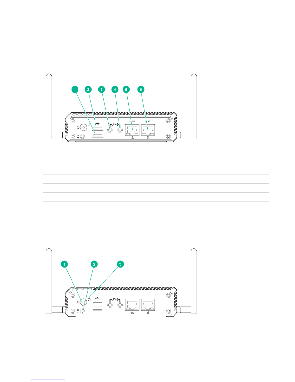
Front panel components
Item Description
1 USB 2.0 connector
2 USB 3.0 connector
3 Audio in
4 Audio out
5 LAN 1 connector
6 LAN 2 connector
Front panel LEDs and buttons
6 Component identification
Page 7
Item Description Status
1 Power On/Off button LED
2 Drive LED
3 Reset button Press to reset the system
1
The reset button is indented and you might need a tool, such as a pin, to press it.
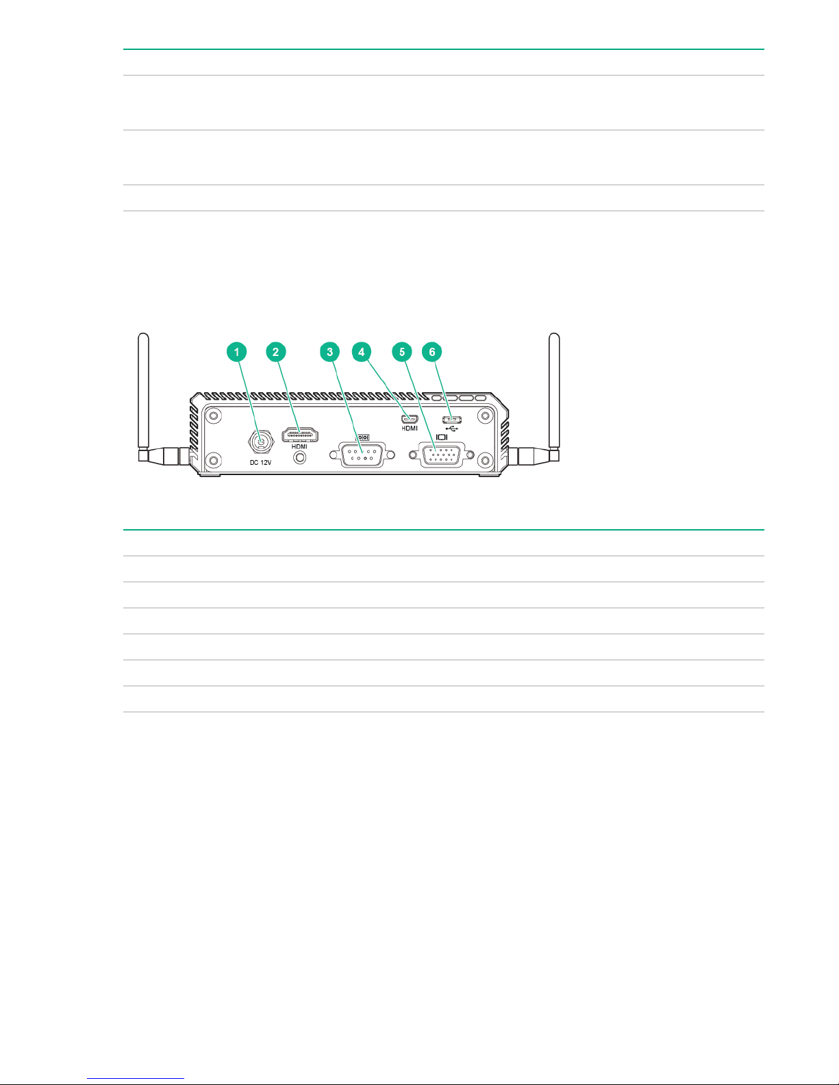
Rear panel components
• Solid green = System on
• Off = System off
• Solid or blinking white = Drive active
• Off = Drive not active
1
Item Description
1 Power connector
2 HDMI connector
3 Serial port connector (RS-232 or RS-422/485)
4 Micro HDMI connector
5 VGA connector
6 Micro USB 2.0 connector
Connector pin assignments
DB9 connector pin assignments for RS422/485
After setting the I/O serial port from serial port 1 to serial port 2, the port supports four-wire RS422/485
signals in half-duplex mode. The DB9 connectors then have the following pin assignments.
Rear panel components 7
Page 8

Pin Assignment
1 Ground
2 CTS+ (HSI+)
3 RTS+ (HSO+)
4 RXD+
5 RXD-
6 CTS- (HSI-)
7 RTS- (HSO-)
8 TXD+
9 TXD-
To set the I/O serial port from port 1 to port 2, see Setting the I/O serial port to RS485 on page 29.
If you need a two-wire RS485 after setting the I/O port to serial port 2, Hewlett Packard Enterprise
recommends that you use an external USB-to-RS485 adapter. For more information and examples for
validating the MODBUS protocol communication, see Validating the MODBUS protocol
communication on page 31.
RS485-solar sensor pin assignments
Pin RS485 pin assignment Solar sensor pin assignment
Orange Data-/B CAN high
Brown Data+/A CAN low
Black Supply (negative) Supply (negative)
Red Supply (positive) Supply (positive)
Black (thick) Shield Shield
Gateway-solar sensor connector pin assignments
Pin Gateway pin assignment RS485 pin assignment RS485 pin color
4 RXD+ Data+/A Brown
5 RXD- Data-/B Orange
8 TXD+ Data+/A Brown
9 TXD- Data-/B Orange
8 RS485-solar sensor pin assignments
Page 9

Operations
Power up the gateway
If the gateway is connected to a power source, it powers up automatically. It needs to be powered up only
after a manual shutdown.
To power up the gateway, press the Power On/Standby button twice.
Power down the gateway
Before powering down the gateway for any upgrade or maintenance procedures, you must back up
critical gateway data and programs.
Use one of the following methods to power down the gateway:
• Press and release the Power On/Standby button.
This method initiates a controlled shutdown of applications and the OS before the gateway enters
standby mode.
• Press and hold the Power On/Standby button for more than 4 seconds to force the gateway to power
down.
This method forces the gateway to power down without properly exiting applications and the OS. If an
application stops responding, you can use this method to force a shutdown.
Before proceeding, you must ensure that the gateway is in standby mode by verifying that the system
power LED is off.
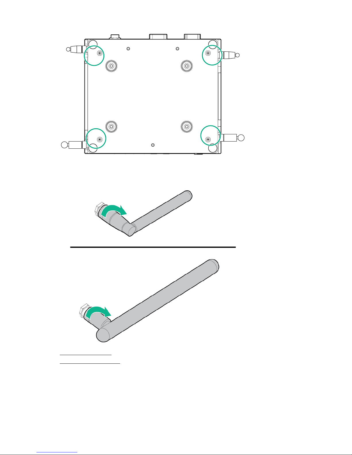
Install the antenna
Procedure
1. Power down the gateway on page 9.
2. Dismount the gateway on page 12.
3. Locate the correct slot for installing the antenna.
Operations 9
Page 10
WAN
WAN
WLAN
WLAN
4. Install the antenna.
5. Mount the gateway on page 10.
6. Power up the gateway on page 9.
Mount the gateway
Use one of the following mounting methods, depending on where and how the gateway is mounted:
10 Mount the gateway
Page 11
• Mounting a wall-mount gateway on page 11
1
1
2
2
2
2
1
2
2
3
1
2
2
3
• Mounting a rack-mount gateway on page 11
• Mounting a VESA-mount gateway on page 12
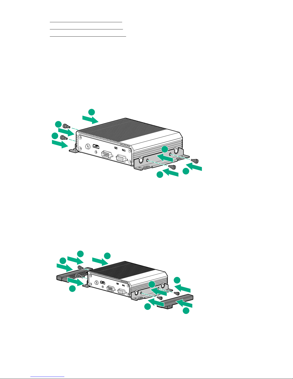
Mounting a wall-mount gateway
Prerequisites
You need four screws for installing the gateway on the wall. The wall-mount screws are not provided with
the wall-mount kit.
Procedure
1. Install the brackets with the four M3.5 screws.
2. Install the gateway on the wall with the four wall-mount screws.
Mounting a rack-mount gateway
Procedure
1. Install the brackets with the four M3.5 screws.
2. Slide the rail mount onto the wall-mount brackets.
Mounting a wall-mount gateway 11
Page 12
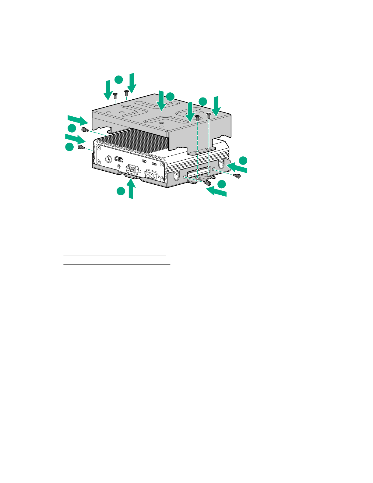
Mounting a VESA-mount gateway
1
3
4
4
2
2
2
2
Procedure
1. Install the bottom bracket with the four M3.5 screws.
2. Install the top-mounting bracket with the four M3 Phillips VESA-mounting bracket screws.
Dismount the gateway
Use one of the following dismounting methods, depending on where and how the gateway is mounted:
• Dismounting a wall-mount gateway on page 12
• Dismounting a rack-mount gateway on page 13
• Dismounting a VESA-mount gateway on page 13
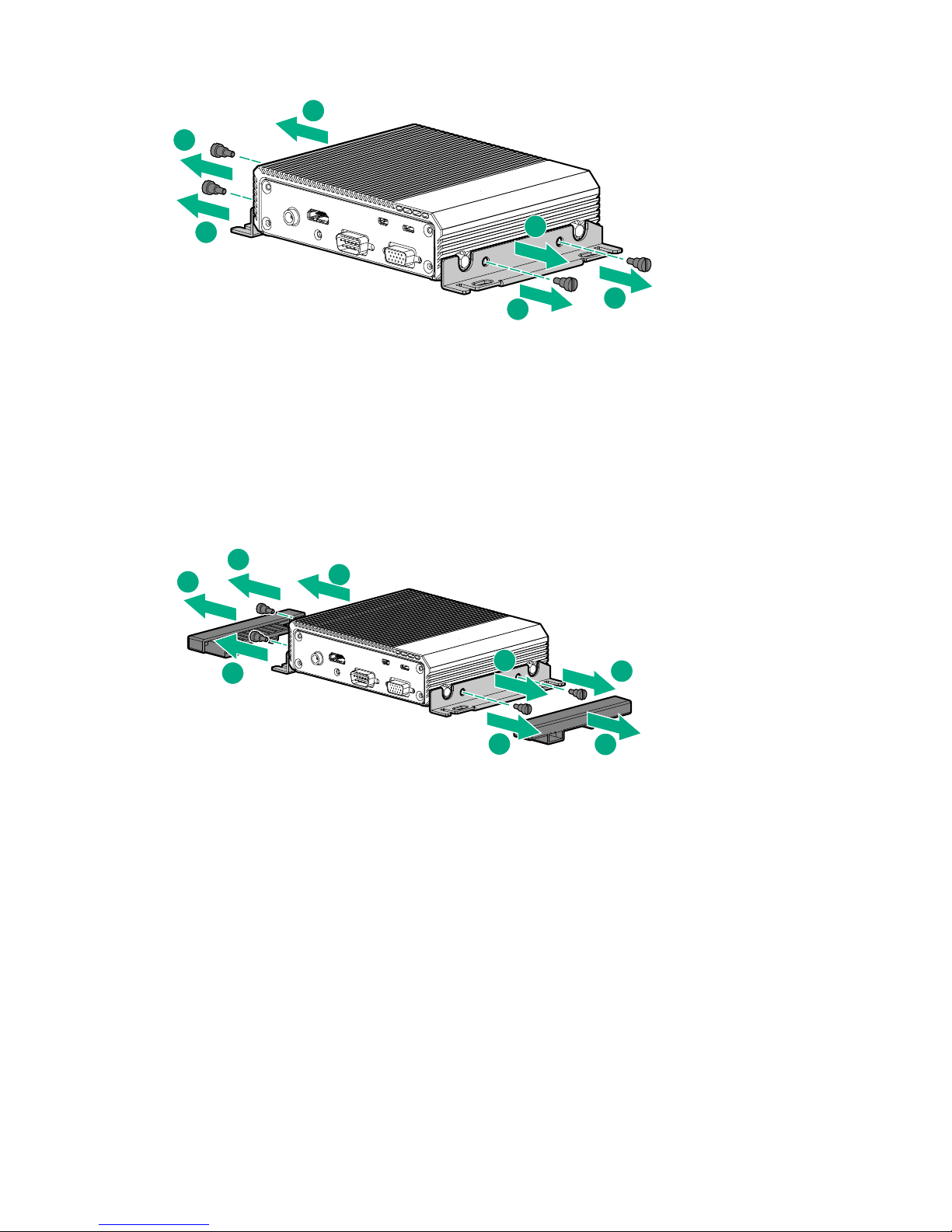
Dismounting a wall-mount gateway
Procedure
1. Remove the screws securing the wall-mount brackets to the wall.
2. Remove the four M3.5 screws securing the wall-mount brackets to the gateway, and then remove the
brackets.
12 Mounting a VESA-mount gateway
Page 13
2
2
1
1
1
1
Dismounting a rack-mount gateway
3
2
2
1
3
2
2
1
Procedure
1. Slide the rail mounts off the wall-mount brackets.
2. Remove the four screws securing the wall-mount brackets to the gateway, and then remove the
brackets.
Dismounting a VESA-mount gateway
Procedure
1. Remove the four M3 Phillips screws securing the VESA-mounting brackets to the gateway.
2. Remove the top-mounting bracket.
3. Remove the four M3.5 screws securing the bottom bracket.
4. Remove the bottom bracket.
Dismounting a rack-mount gateway 13
Page 14
1
1
2
4
3
3
3
3
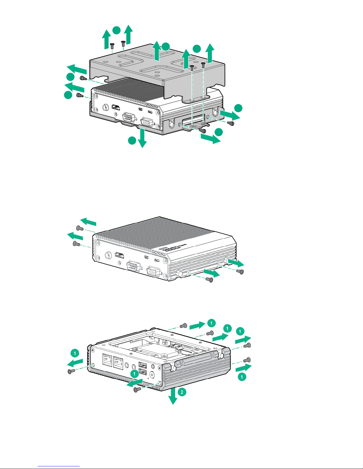
Remove the top access panel
Procedure
1. Remove the top access panel screws.
2. Place the gateway upside down on a flat, level surface.
3. Remove the screws from the front and rear panels, and then remove the top access panel.
14 Remove the top access panel
Page 15
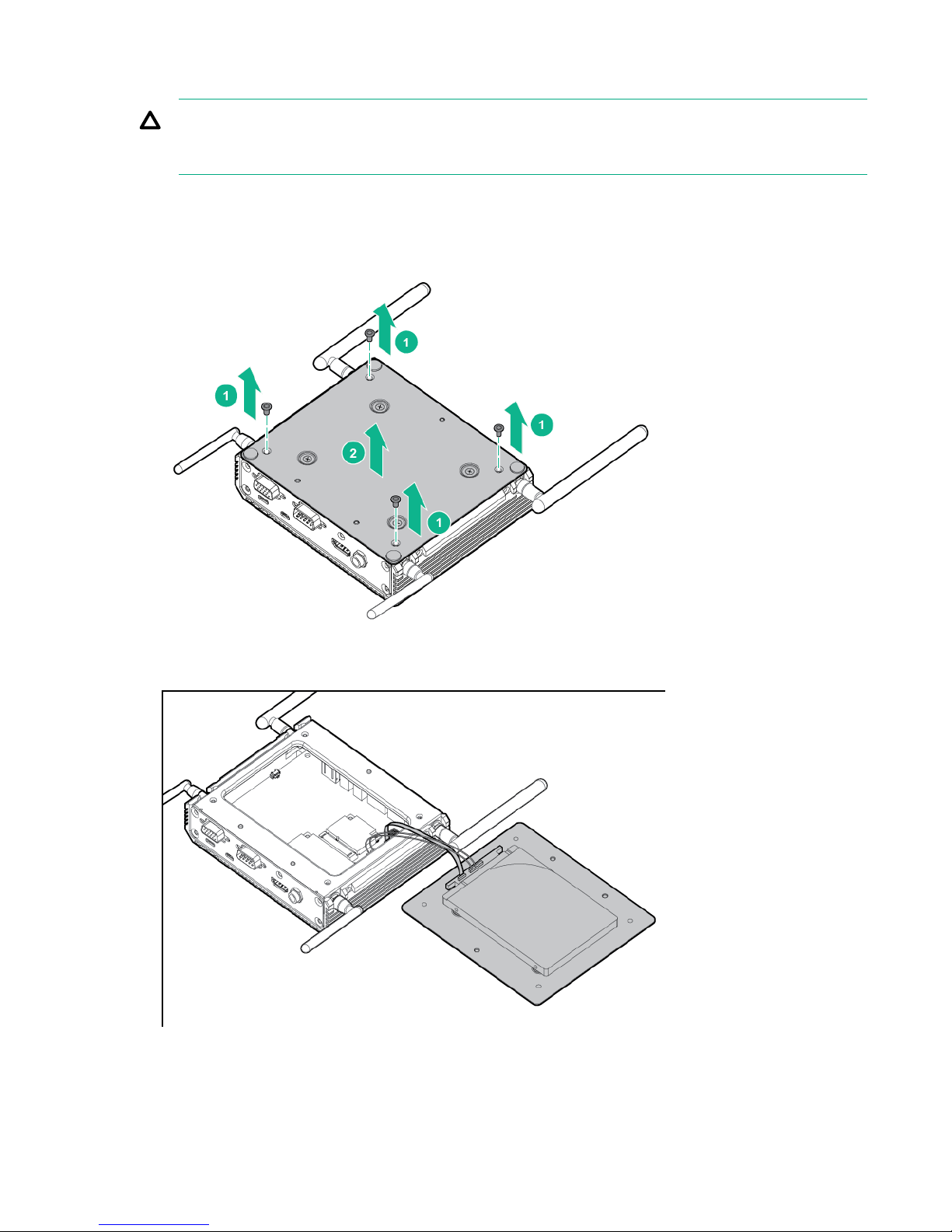
Remove the bottom access panel
CAUTION:
Before placing the gateway upside down, turn the antennas parallel with the table surface to avoid
breaking the antennas.
Procedure
1. Using a T-10 Torx head screwdriver, remove the four Torx head screws securing the access panel to
the bottom of the gateway.
2. Lift the access panel up, and then set it to the side. The jumper cables connecting the drive are still
attached.
Remove the bottom access panel 15
Page 16

Setup
Optional services
Hewlett Packard Enterprise offers the HPE Foundation Care Next Business Day Exchange Service for
this product.
HPE Foundation Care Next Business Day Exchange Service provides a replacement product or part
delivered free of freight charges to your location the next business day after a call is opened and provides
support 24 hours per day, Monday through Sunday.
Hardware exchange offers a reliable and fast parts exchange service for eligible Hewlett Packard
Enterprise products. Specifically targeted at products that can easily be shipped and on which you can
easily restore data from backup files, HPE Foundation Care Next Business Day Exchange is a costefficient and convenient alternative to onsite support.
Replacement products or parts are new or equivalent to new in performance.
In addition, HPE Foundation Care Next Business Day Exchange provides electronic access to related
product and support information, enabling any member of your IT staff to locate commercially available
essential information.
For more information on HPE Foundation Care Next Business Day Exchange Service, see the
Packard Enterprise website.
Optimum environment
When installing the gateway, select a location that meets the environmental standards.
• Temperature requirements on page 16
• Power requirements on page 16
Temperature requirements
To ensure continued safe and reliable equipment operation, install or position the gateway in a wellventilated, climate-controlled environment.
Configuration Temperature
System with no modules installed Operating temperature of up to 60°C (140°F)
WiFi option without extended ambient temperature
support
WiFi option with extended ambient temperature support -20°C to 60°C (-4°F to 140°F)
3G option -20°C to 45°C (-4°F to 113°F)
Hewlett
0°C to 45°C (32°F to 113°F)
Power requirements
Installation of this equipment must comply with local and regional electrical regulations governing the
installation of information technology equipment by licensed electricians. This equipment is designed to
operate in installations covered by NFPA 70, 1999 Edition (National Electric Code) and NFPA-75, 1992
(code for Protection of Electronic Computer/Data Processing Equipment). For electrical power ratings on
options, see the product rating label or the user documentation supplied with that option.
For more information on power requirements, see Power supply specifications on page 53.
16 Setup
Page 17

Installing hardware options
Install any hardware options before initializing the gateway. For options installation information, see the
option documentation. For gateway-specific information, see Hardware options installation on page
24.
Installing the operating system
The HPE IoT gateway s are standard, Intel-based PC server systems. However, the gateway does not
include a CD or DVD-ROM device for installing the OS. To install a
gateway, you can use one of the following methods:
• Installing using a USB key with an ISO image
• Installing using local media
• Installing using PXE boot via network
Installing OS using a USB key
To install an OS using a USB key, you must perform the following procedures:
• Create an ISO-imaged USB key
• Install the OS using the imaged USB key
Create an ISO-imaged USB key
supported operating system in the
Procedure
1. On a separate workstation, download the RUFUS utility.
2. Download the portable option of the RUFUS utility.
3. Run the RUFUS utility.
Installing hardware options 17
Page 18
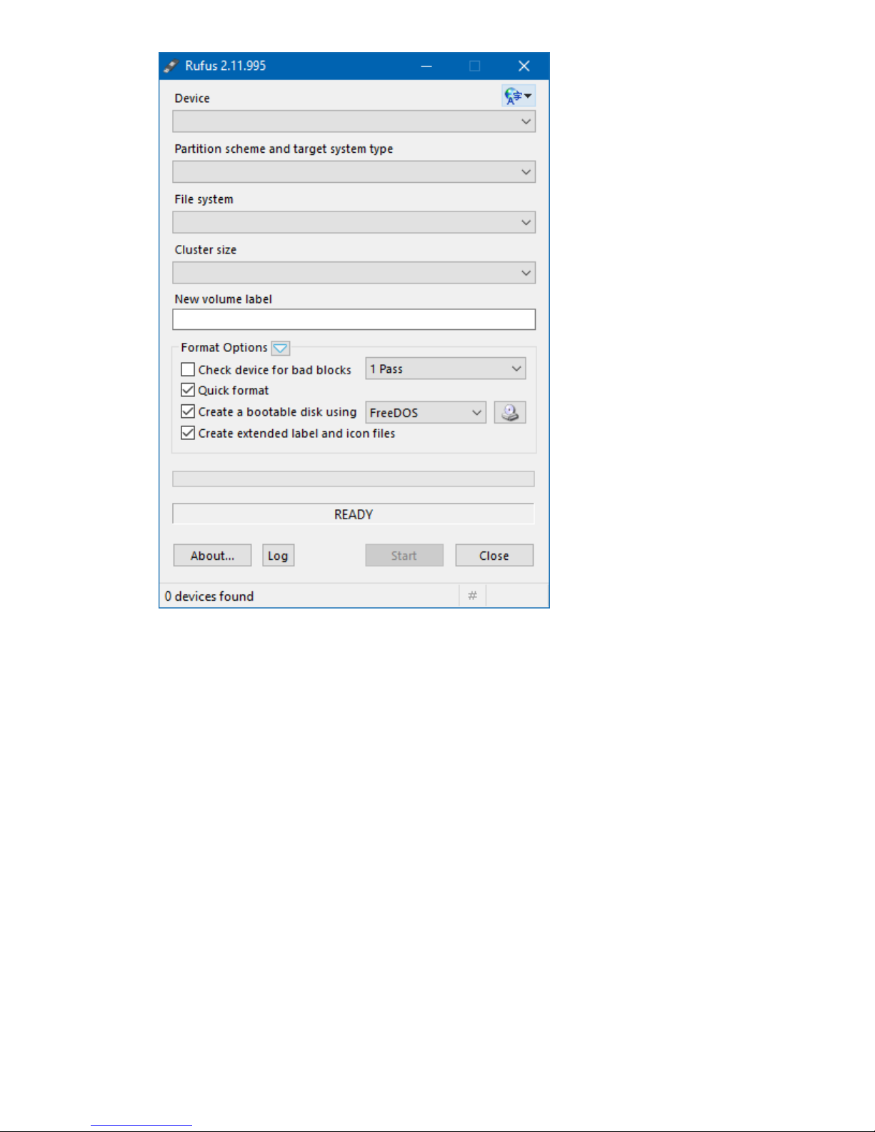
4. Insert a USB drive into the workstation.
The RUFUS utility will automatically detect the USB drive and display the drive details.
18 Setup
Page 19

5. Select ISO image from the Create a bootable disk using drop-down.
6. Click the disk icon, and select the ISO image of the required OS.
7. Confirm that Standard Windows installation is selected.
Setup 19
Page 20

8. Click the Start button to begin the USB key imaging process.
It will take approximately 15 minutes for the imaging process to complete.
9. Click the Close button to close the RUFUS utility.
10. Safely remove the imaged USB key from the workstation.
Install OS using the imaged USB
Prerequisites
The gateway must be powered off before starting this procedure.
Procedure
1. Insert the USB key into the gateway.
2. Power up the gateway on page 9.
3. Access the System BIOS settings (Accessing the system BIOS on page 39).
4. Navigate to the Boot tab.
For information on navigating the BIOS menu, see Navigating and modifying menu options on
page 40.
20 Install OS using the imaged USB
Page 21

5. Select Hard Drive BBS Priorities.
6. Select Boot Option #1 under Boot Option Priorities.
A menu for selecting the Boot Option #1 is displayed.
7. Select the USB key as Boot Option #1.
Setup 21
Page 22

8. Press the Escape key.
9. Navigate to the Save & Exit tab.
10. Select Boot Override.
11. Select the USB key option.
22 Setup
Page 23

12. Press Enter.
13. Follow the OS installation prompts to complete the OS installation on the device.
Wait for the OS installation to complete.
14. Remove the USB key from the gateway.
The OS installation from the USB key is complete. The gateway boots from the new HDD at reboot.
Installing OS using local media
You can use local media such as a USB CD, DVD, or disk drive with installation media to install the OS.
To install the OS, access the System BIOS settings.
The last BIOS screen will enable you to select your installation media, temporarily overriding the default
boot order.
Registering the product
To experience quicker service and more efficient support, register the product at the Hewlett Packard
Enterprise Product Registration website.
Installing OS using local media 23
Page 24

Hardware options installation
WAN
WAN
Installing the 3G module
Only one (half-length or full-length) module can be installed at a time.
Prerequisites
• Use only HPE approved 3G modules. Non HPE approved modules might not be compatible with the
system. For more information on HPE approved modules, see the product QuickSpecs on the Hewlett
Packard Enterprise website (http://www.hpe.com/info/qs).
• The 3G module option will work only if a SIM card is installed in the system. Be sure to purchase a
SIM card while purchasing a 3G module.
Procedure
1. Power down the gateway on page 9.
2. Dismount the gateway on page 12.
3. Remove the bottom access panel on page 15.
4. Install the SIM card.
5. Using a T-10 Torx screwdriver, install the 3G module using at least one screw to secure the module.
Hewlett Packard Enterprise recommends installing the screws on the board before inserting the
module into the board.
6. Connect the two antenna cables to the antenna connectors on the 3G module.
24 Hardware options installation
Page 25

WAN
WAN
7. Connect SIM cable to drive.
8. Install the bottom access panel.
9. Install the antenna on page 9.
10. Mount the gateway on page 10.
11. Power up the gateway on page 9.
Installing the half-length WiFi/WLAN module
Procedure
1. Power down the gateway on page 9.
2. Dismount the gateway on page 12.
3. Remove the bottom access panel on page 15.
4. Using a T-10 Torx screwdriver, install the half-length WiFi module using at least one screw to secure
the module.
Installing the half-length WiFi/WLAN module 25
Page 26

Hewlett Packard Enterprise recommends installing the screws on the board before inserting the
WLAN
WLAN
WLAN
WLAN
module into the board.
5. Connect the two antenna cables to the antenna connectors on the half-length WiFi module.
6. Install the bottom access panel.
7. Install the antenna on page 9.
8. Mount the gateway on page 10.
9. Power up the gateway on page 9.
Installing the full-length WiFi/WLAN module
Procedure
1. Power down the gateway on page 9.
2. Dismount the gateway on page 12.
3. Remove the bottom access panel on page 15.
26 Installing the full-length WiFi/WLAN module
Page 27

4. Using a T-10 Torx screwdriver, install the full-length WiFi module using at least one screw to secure
WLAN
WLAN
WLAN
WLAN
the module.
Hewlett Packard Enterprise recommends installing the screws on the board before inserting the
module into the board.
5. Connect the two antenna cables to the antenna connectors on the full-length WiFi module.
6. Install the bottom access panel.
7. Install the antenna on page 9.
8. Mount the gateway on page 10.
9. Power up the gateway on page 9.
Hardware options installation 27
Page 28

Configuration
1
2
3
Jumper settings
Jumpers are used to close electric circuits. You can configure cards by setting the jumpers in the system.
Setting the jumpers
Prerequisites
Before setting the jumper or clearing CMOS, you must turn off the power supply to avoid damaging the
computer. Before powering on the power supply, you must ensure that the CMOS jumper is back to 3.0
V Battery On.
You will need a standard cable to make the connections.
For more information about the best hardware configuration for your gateway, contact an authorized
reseller or an authorized service provider.
Procedure
1. Power down the gateway on page 9.
2. Dismount the gateway on page 12.
3. Remove the bottom access panel on page 15.
4. Locate the jumper.
Item Pin number
1 1
2 2
3 3
5. Set the jumpers by installing the jumper clip on the pins. Jumpers can be set to the following modes in
this system:
28 Configuration
Page 29

AT mode (default): In this mode, the gateway turns on when power is applied.
Item Description
1 Pin 1
2 Pin 2
3 Pin 3
ATX mode: In this mode, the gateway turns on only when the power button is pressed.
Item Description
1 Pin 1
2 Pin 2
3 Pin 3
6. Install the bottom access panel.
7. Mount the gateway on page 10.
8. Power up the gateway on page 9.
Setting the I/O serial port to RS485
Procedure
1. Power down the gateway on page 9.
2. Dismount the gateway on page 12.
3. Remove the bottom access panel on page 15.
4. Disconnect the drive cables.
Setting the I/O serial port to RS485 29
Page 30

5. Remove the top access panel on page 14.
NOTE:
Do not pull on the cable to disconnect it from the port. Instead, disconnect the connector itself.
Pulling on the cable can damage the cable or the connector.
6. Disconnect the I/O serial port cable from the I/O serial port 1 connector.
7. Connect the I/O serial port cable to the I/O serial port 2 connector. For connector pin assignments,
see DB9 connector pin assignments for RS422/485 on page 7.
30 Configuration
Page 31

8. Install the top access panel.
9. Connect the drive cables.
10. Install the bottom access panel.
11. Mount the gateway on page 10.
12. Power up the gateway on page 9.
Validating the MODBUS protocol communication
You can use the following tests and methods to validate MODBUS protocol communication:
• Computer-Gateway communication test
• Computer-solar sensor communication test
• Gateway-solar sensor communication test
Testing communication between computer and Gateway system
Procedure
1. Install the USB to RS485 adaptor driver.
A virtual serial port opens and displays the following message:
"Prolific USB-to-Serial Comm Port (COM5)."
For information on pin connector assignments, see DB9 connector pin assignments for RS485.
2. Route the cables:
a. Connect the Data+ to RX+ and RX+ to TX+ cable with a 120 ohm resistor in-between.
b. Connect the Data- to RX- and RX- to TX+ cable with a 120 ohm resistor in-between.
The serial port is configured with the following parameters:
• Speed: 9600
• Data bits: 8
• Stop bits: 1
Validating the MODBUS protocol communication 31
Page 32

• Parity: None
• Flow Control: None
3. Send a command string from the computer to the Gateway.
If the communication between the computer and the Gateway is established, the Gateway receives
the command string.
4. Send a command string from the Gateway to the computer.
If the communication between the Gateway and the computer is established, the computer receives
the command string.
NOTE:
While sending data, the receive pin on the Gateway also receives the sent data because TX and
RX cables are wired together. To fix this issue, disable the receive I/O of the Gateway when
sending data (requires software implementation).
Testing communication between computer and solar sensor
Procedure
1. Install the USB to RS485 adaptor:
• Connect adaptor pin 1 to the solar sensor Data+/B pin.
• Connect adaptor pin 1 to the solar sensor Data-/A pin.
For pin connector assignments, see RS485-solar sensor connector pin assignments.
2. Install the USB to RS485 adaptor driver.
3. Launch the Si Modbus Configurator application.
4. Reset the power supply:
a. Disconnect the power cable from the gateway.
b. Connect the power cable to the gateway.
Wait till the Sensor connected LED glows green.
32 Testing communication between computer and solar sensor
Page 33

5. Click the Switch to MODBUS mode button.
6. Select the required MODBUS functions.
7. Click the Send button.
The application sends the MODBUS command to RS485 and reads the response.
To change the application back to configuration mode, click the Switch to Configuration Mode
button. To set RS485 to configuration mode, you must reset the RS485.
Testing communication between Gateway and solar sensor
Prerequisites
This option is supported only with Linux OS.
Procedure
1. Connect the Gateway to the solar sensor:
a. Connect Gateway pins 4 and 8 to RS485 Data+/A port.
b. Connect Gateway pins 5 and 9 to RS485 Data-/B port.
For connector pin assignments, see Gateway-solar sensor connector pin assignments.
The Modbus master receives signals immediately and can now query any data from the device.
Testing communication between Gateway and solar sensor 33
Page 34

Software and configuration utilities
Supported operating systems and drivers matrix
Operating system support
For more information on Hewlett Packard Enterprise Certified and Supported systems for the operating
systems available for your system, see the Hewlett Packard Enterprise OS support website:
http://www.hpe.com/info/ossupport
ROM, BIOS, and driver support
For more information on Hewlett Packard Enterprise Certified and Supported systems for the latest
software ROM, BIOS, and drivers available for your system, see the Hewlett Packard Enterprise Support
Center website:
http://www.hpe.com/support/hpesc
Product QuickSpecs
For more information about product features, specifications, options, configurations, and compatibility, see
the product QuickSpecs on the Hewlett Packard Enterprise website (http://www.hpe.com/info/qs).
System BIOS
Updating the system BIOS
You can download the latest system BIOS, whenever updates are available, from the Hewlett Packard
Enterprise Support Center website (http://www.hpe.com/info/ossupport).
For more information on product entitlement, and accessing product updates, see Accessing updates
on page 56.
Prerequisites
• You need an empty USB drive that is FAT32 formatted for saving the utility and bin files for updating
the system BIOS.
• Product entitlement is required to perform updates.
Procedure
1. Go to the Hewlett Packard Enterprise Support Center website.
2. Download the afuefix64.efi utility and <xxxxx> BIOS bin files to the USB drive.
3. Remove the USB drive and connect it to the system.
4. Power up the gateway on page 9.
5. Access the system BIOS (Accessing the system BIOS on page 39).
6. Locate the BIOS version.
If the Build Date is 12/10/2015, the BIOS must be updated.
34 Software and configuration utilities
Page 35

7. Set UEFI: Built-in EFI Shell as Boot Option #1.
8. Select Save Changes and Exit.
The settings changes made so far will take effect only if you save and exit.
Software and configuration utilities 35
Page 36

The system will now boot to the Shell. The following is a sample screen:
If your screen looks different from the sample screen provided, reset the UEFI: Built-in EFI Shell to
Boot Option #1.
9. Identify the USB drive.
The following is a sample screen with fs1 as the USB drive.
10. Initiate the BIOS update:
a. To select the USB drive, enter the fs1: command.
b. To ensure that both the utility and bin files are visible, enter the dir command.
36 Software and configuration utilities
Page 37

c. To initiate the update, enter the AfuEfix64.efi XXXX.bin /P /B /N /X command.
In the following sample, the command is: AfuEfix64.efi L510K112.BIN /P /B /N /X
You will see a screen similar to the following while the update is in progress:
After the update, one of the following screens appear:
Software and configuration utilities 37
Page 38

• An error screen showing that the BIOS does not support ME Entire Firmware update. The
following is a sample screen:
To fix this error, repeat the steps from accessing the BIOS to save changes and exit, and then
run the update again.
• A screen showing that the BIOS update was successful. The following is a sample screen:
11. Power down the gateway on page 9 for the changes to take effect.
All BIOS options are restored to the default values and the Management Engine password is set back to
the default password.
The Build Date now appears updated to 06/13/2017 on the BIOS Main tab. The ME FW version is now
9.5.61.3012.
38 Software and configuration utilities
Page 39

Using the system BIOS to configure gateway and troubleshoot issues
The gateway can be set up and configured through the system BIOS. The system BIOS also has options
for restoring default configurations and resetting the system. The setup information is stored in the
battery-backed CMOS, therefore it retains the setup information even when the power is turned off.
For more information, see "Setting up the system BIOS."
Accessing the system BIOS
Procedure
1. Connect KVM to the gateway.
2. Power up the gateway.
3. Press the Delete key or the F2 key.
The BIOS Main tab is displayed.
Setting up the system BIOS
BIOS menu components
The BIOS menu has the following frames:
• Left frame—Displays the sub menu. Only the sub-menu options in blue can be modified. When an
option is selected in the left frame, it is highlighted in white.
• Top right frame—Displays information about the sub-menu option selected.
• Bottom right frame—Displays the keys to use to make changes to the selected sub menu.
Using the system BIOS to configure gateway and troubleshoot issues 39
Page 40

Navigating and modifying menu options
Procedure
1. Access the system BIOS.
2. Press the right arrow key to navigate to the tab to modify.
3. Press the up and down arrow keys to navigate to the sub-menu options on the left frame.
4. When you reach a sub-menu option to modify, press the Enter key.
5. Press the + key or the - key to modify the setting selected.
6. Do one of the following:
• Press the F4 key to save the new setting and exit.
• Press the Esc key to exit without saving.
Main tab
The Main tab displays general BIOS information including the following menu options:
• System Date
• System Time
Setting the System Date and System Time
Procedure
1. Access the system BIOS Main tab.
2. Press the up and down arrow keys to navigate to the sub-menu options on the left frame.
3. When you reach a sub-menu option to modify, press the Enter key.
4. Press the Tab key or the arrow keys to navigate the fields.
5. Enter the new values.
The date must be entered in the MM/DD/YY format. The time must be entered in the HH:MM:SS
format.
6. Do one of the following:
40 Navigating and modifying menu options
Page 41

• Press the F4 key to save the new values and exit.
• Press the Esc key to exit without saving.
Advanced tab
The Advanced tab includes the following menu options:
• Trusted Computing
• Intel (R) Smart Connect Technology
• CPU Configuration
• PPM Configuration
• IDE Configuration
• Miscellaneous Configuration
• CSM Configuration
• USB Configuration
• Security Configuration
Trusted Computing
General status and security configuration settings are displayed, including:
• Security Device Support—Enables or disables Security Device Support
• TPM State—Enables or disables TPM State
• TPM Enabled Status—Displays whether TPM is enabled or disabled
• TPM Active Status—Displays whether TPM is active or inactive
Advanced tab 41
Page 42

ACPI Settings
• Enable ACPI Auto Configuration—Enables or disables the BIOS ACPI auto configuration
• Enable Hibernation—Enables or disables system hibernation (OS/S4 sleep state) settings. This
option may not be effective with some operating systems.
• ACPI Sleep State—Selects the highest ACPI sleep state the system will enter when the SUSPEND
button is pressed
• Lock Legacy Resources—Enables or disables lock legacy device resources
Intel (R) Smart Connect Technology
ISCT Support—Enables or disables BIOS ISCT support
CPU Configuration
Displays general CPU configuration values, including socket CPU information
PPM Configuration
• CPU C-state Report—Enables or disables CPU C-state report to OS
• Max CPU C-state—Enables user to control the Max C-state that the processor will support
• S0ix—Enables or disables CPU S0ix state
IDE Configuration
• Serial-ATA (SATA)—Enables or disables Serial ATA. The internal disk might not be usable if this
option is disabled.
• SATA Speed Support—Displays whether SATA Speed Support is Gen1 or Gen2
• SATA ODD Port—Displays whether SATA ODD is Port1 or No ODD
• SATA Mode—Enables user to select IDE or AHCI modes
• mSATA—Enables or disables mSATA function. If mSATA is not installed, this function is disabled.
• Serial-ATA Port 1—Enables or disables Serial ATA Port
• SATA port2 HotPlug—Enables or disables Serial ATA Port 2 hot-plug function
Miscellaneous Configuration
• High Precision Timer—Enables or disables the High Precision Event Timer
• PCI Express Dynamic Clock Gating—Enables user to adjust PCI express clock
• OS selection—Enables user to select OS: Windows 8.X/Windows 7/Android
CSM Configuration
• CSM Support—Enables or disables CSM support
• GateA20 Active:
◦ UPON REQUEST—GA20 can be disabled using BIOS services.
◦ ALWAYS—Do not allow disabling GA20. This option is useful when any RT code is executed above
1 MB.
• Option ROM Messages—Enables user to set display mode for Option ROM to Force BIOS or Keep
Current
NOTE: The system default is UEFI and Legacy, which can support all operating systems.
However, if you are using Secure Boot Mode, select UEFI Only.
• Boot option filter—Enables user to control Legacy/UEFI ROMs priority
42 ACPI Settings
Page 43

• Storage—Enables user to control the execution of UEFI and Legacy Storage Option ROM
• Video—Enables user to control the execution of UEFI and Legacy Video Option ROM
• Other PCI devices—Enables user to set Option ROM execution policy for devices other than
Network, Storage, or Video
USB Configuration
• Legacy USB Support—Enables user to set support for legacy USB. Auto option disables legacy
support if no USB devices are connected.
• XHCI Hand-off—Offers user a workaround for the OS without XHCI hand-off support. The XHCI
ownership change should be claimed by the XHCI driver.
• EHCI Hand-off—Offers user a workaround for the OS without EHCI hand-off support. The EHCI
ownership change should be claimed by the EHCI driver.
• USB Mass Storage Driver Support—Enables or disables mass storage support
• USB transfer time out—Enables user to set the time-out value for control, bulk, and interrupt
transfers
• Device reset time out—Enables user to set the USB mass storage device start unit command timeout value
• Device power up delay—Enables user to set the maximum time the device will take before it properly
reports itself to the Host Controller. 'Auto' uses default value: for a Root port it is 100 ms: for a Hub
port the delay is taken from Hub descriptor.
Security Configuration
• TXE—Enables or disables TXE
• TXE HMRFPO—Enables or disables TXE HMRFPO
• TXE Firmware Update—Enables or disables automatic firmware updates for TXE
• TXE EOP Message—Enables or disables TXE to send an EOP Message before entering
• Intel (R) AT—Enables or disables BIOS AT code from running
• Intel (R) AT Platform PBA—Enables or disables BIOS AT code from running
Chipset tab
The Chipset tab displays general configuration details including the following menu options:
• North Bridge—Details of North Bridge parameters
• South Bridge—Details of South Bridge parameters
USB Configuration 43
Page 44

North Bridge sub-menu options
Intel IGD Configuration—Enables user to configure Intel IGD settings
•
•
Graphics Power Management Control—Enables user to set graphics power management control
options
• LCD Control—Enables user to set LCD control
• Memory Information—Displays memory frequency and timing setting information
• Max TOLUD—Displays the maximum value of TOLUD
Intel IGD Configuration
• GOP Configuration—Displays GOP driver option
• GOP Driver—Enables GOP driver to unload VBIOS. Disable GOP driver to load BIOS.
• Integrated Graphics Device—Enables or disables Intel IGD. Enable when selected as the Primary
Video Adapter.
• IGD Turbo Enable—Enables or disables IGD turbo function
• Primary Display—Enables user to select which IGD/PCI graphics device should be the primary
display
• GFX Boost—Enables or disables GFX boost function
• PAVC—Enables or disables PAVC
• DVMT Pre-Allocated—Enables user to select DVMT 5.0 pre-allocated (fixed) graphics memory size
used by the IGD
• DVMT Total Gfx Mem—Enables user to select DVMT 5.0 total graphic memory size used by the IGD
• Aperture Size—Enables user to select the aperture size
• DOP CG—Enables or disables DOP clock gating
• GTT Size—Enables user to select the GTT size
• IGD Thermal—Enables or disables IGD thermal
• Spread Spectrum clock—Enables or disables spread spectrum clock
• ISP Enable/Disable—Enables or disables ISP PCI device selection
• ISP PCI Device Selection—Enables user to select ISP PCI. Default ISP is PCI B0D2F0 for Windows
Boot. Perform Linux Boot to select B0D3G0.
• VCC_Vnn for Power State2—Enables or disables VCC_Vnn power state2
Graphics Power Management Control
RC6 (Render Standby)—Enables or disables render standby support
44 North Bridge sub-menu options
Page 45

LCD Control
• Primary IGFX Boot Display—Enables user to select the video device that will be activated during
POST. VGA mode is only supported on primary display.
• LVDS Panel Type—Enables and selects LCDS type or disables LVDS function
South Bridge sub-menu options
Azalia HD Audio —Displays Azalia HD audio options
•
• USB Configuration —Displays USB configuration settings
•
PCI Express Configuration —Displays PCI Express configuration settings
• LPSS and SCC Devices Mode—Displays LPSS and SCC device mode settings
• LAN1 Control—Enables or disables LAN1
◦ LAN1 PXE Option ROM—Enables or disables boot option for LAN1 Controller
• LAN2 Control—Enables or disables LAN2
◦ LAN2 PXE Option ROM—Enables or disables boot option for LAN2 Controller
• Global SMI Lock—Enables or disables SMI lock
• BIOS Read/Write Protection—Enables or disables BIOS SPI region read/write protect
Audio Configuration
Audio Controller—Enables or disables the detection of the Azalia device
USB Configuration
• XHCI Mode—Enables and selects the mode of operation of XHCI controller
• USB2 Link Power Management—Enables or disables USB2 Link Power Management
• USB 2.0(EHCI) Support—Enables user to control the USB EHCI (USB 2.0) functions. One EHCI
controller must always be enabled.
PCI Express Configuration
• Mini PCI Express—Enables or disables mini-PCI Express port
◦ Hot Plug—Enables or disables mini-PCIe hot-plug function
◦ Speed—Enables user to select PCIe port speed
• Extra Bus Reserved—Enables or disables extra bus reserved (0-3) for bridges behind the root bridge
• Reserved Memory—Enables user to select the amount of reserved memory
• Reserved Memory Alignment—Enables user to select the amount of reserved memory alignment
• Prefetchable Memory—Enables user to select the amount of prefetchable memory
• Prefetchable Memory Alignment—Enables user to select the amount of prefetchable memory
alignment
• Reserved I/O—Enables user to select the amount of reserved I/O
Security tab
The Security tab displays password information including the following menu options:
• Administrator Password—Enables user to set administrator password
• User Password—Enables user to set user password
• Secure Boot
• Secure Flash Update—Enables user to update secure flash
South Bridge sub-menu options 45
Page 46

Secure Boot
• Secure Boot—Enables or disables secure boot function
• Secure Boot Mode—Enables user to select secure boot mode
Boot tab
The Boot menu includes the following menu options:
• Setup Prompt Timeout—Displays the number of seconds to wait for setup activation key
• Bootup NumLock State—Enables user to select the keyboard NumLock state
• Quiet Boot—Enables or disables the Quiet Boot option
• Fast Boot—Enables or disables the Fast Boot option
• Boot Option Priorities—Enables user to set the system boot priority order
• Network Device BBS Priorities—Enables user to set the order of network devices
• Hard Drives BBS Priorities—Enables user to set the order of legacy devices
Save & Exit tab
The Save & Exit menu tab includes the following menu options:
46 Secure Boot
Page 47

• Save Changes and Exit—Enables user to exit system setup after saving changes
• Discard Changes and Exit—Enables user to exit system setup without saving any changes
• Save Changes and Reset—Enables user to reset the system after saving the changes
• Discard Changes and Reset—Enables user to reset the system without saving the changes
• Save Changes—Enables user to save changes made so far to any of the options
• Discard Changes—Enables user to discard changes made so far to any of the options
• Restore Defaults—Enables user to restore/load default values for all the options
• Save as User Defaults—Enables user to save the changes made so far as user defaults
• Restore User Defaults—Enables user to restore the user defaults to all the options
• Boot Override—Enables user to override your boot priority
Software and configuration utilities 47
Page 48

Troubleshooting
Troubleshooting resources
The HPE IoT Gateway GL10 (Formerly HPE EL10 Intelligent Gateway) Maintenance and Service Guide
includes additional troubleshooting resources and is available on the Hewlett Packard Enterprise website
http://www.hpe.com/info/edgeline-docs.
48 Troubleshooting
Page 49

Battery
Battery specifications
Feature Specification
Type CR2032 RTC batteries with a rating of 210 mAh
Power Battery RTC circuitry draws 2uA when in use (system off)
Maximum Battery
Life Cycle
Maximum Battery
Life Cycle under
Storage Mode
Maximum Battery
Life Cycle under
Operation Mode
210 mAh/2 uAh = 10,5000 hours
105000 hours/(365 x 24) = 11.98 years
(Battery in Storage Mode - System Powered Off all day, RTC battery is in use)
105000 hours/(365 x (24-8)) = 17.97 years
(Battery in Operation Mode - System Power On, 8 hours/day, RTC circuitry does
not use battery power when system is on)
Battery 49
Page 50

Warranty and regulatory information
Warranty information
To view the warranty for your product or to view the Safety and Compliance Information for Server,
Storage, Power, Networking, and Rack Products reference document, go to the Enterprise Safety and
Compliance website:
www.hpe.com/support/Safety-Compliance-EnterpriseProducts
Additional warranty information
HPE ProLiant and x86 Servers and Options
www.hpe.com/support/ProLiantServers-Warranties
HPE Enterprise Servers
www.hpe.com/support/EnterpriseServers-Warranties
HPE Storage Products
www.hpe.com/support/Storage-Warranties
HPE Networking Products
www.hpe.com/support/Networking-Warranties
Regulatory information
To view the regulatory information for your product, view the Safety and Compliance Information for
Server, Storage, Power, Networking, and Rack Products, available at the Hewlett Packard Enterprise
Support Center:
www.hpe.com/support/Safety-Compliance-EnterpriseProducts
Additional regulatory information
Hewlett Packard Enterprise is committed to providing our customers with information about the chemical
substances in our products as needed to comply with legal requirements such as REACH (Regulation EC
No 1907/2006 of the European Parliament and the Council). A chemical information report for this product
can be found at:
www.hpe.com/info/reach
For Hewlett Packard Enterprise product environmental and safety information and compliance data,
including RoHS and REACH, see:
www.hpe.com/info/ecodata
For Hewlett Packard Enterprise environmental information, including company programs, product
recycling, and energy efficiency, see:
www.hpe.com/info/environment
Belarus Kazakhstan Russia marking
Manufacturer and Local Representative Information
50 Warranty and regulatory information
Page 51

Manufacturer information:
Hewlett Packard Enterprise Company, 3000 Hanover Street, Palo Alto, CA 94304 U.S.
Local representative information Russian:
• Russia:
• Belarus:
• Kazakhstan:
Local representative information Kazakh:
• Russia:
• Belarus:
• Kazakhstan:
Manufacturing date:
The manufacturing date is defined by the serial number.
CCSYWWZZZZ (serial number format for this product)
Valid date formats include:
• YWW, where Y indicates the year counting from within each new decade, with 2000 as the starting
point; for example, 238: 2 for 2002 and 38 for the week of September 9. In addition, 2010 is indicated
by 0, 2011 by 1, 2012 by 2, 2013 by 3, and so forth.
• YYWW, where YY indicates the year, using a base year of 2000; for example, 0238: 02 for 2002 and
38 for the week of September 9.
Turkey RoHS material content declaration
Turkey RoHS material content declaration 51
Page 52

Ukraine RoHS material content declaration
Japanese certification mark for 3G module
52 Ukraine RoHS material content declaration
Page 53

Specifications
Product QuickSpecs
For more information about product features, specifications, options, configurations, and compatibility, see
the product QuickSpecs on the Hewlett Packard Enterprise website (
Environmental specifications
Specification Value
Temperature range
Operating -20°C to 60°C (-4°F to 140°F)
Nonoperating -40°C to 60°C (-40°F to 140°F)
Relative humidity (noncondensing) 40% to 95% relative humidity
1
All temperature ratings shown are for sea level. An altitude derating of 1.0°C per 304.8 m (1.8°F per 1000 ft) to 3048
m (10,000 ft) is applicable. No direct sunlight allowed. Maximum rate of change is 20°C per hour (36°F per hour).
Mechanical specifications
1
http://www.hpe.com/info/qs).
—
Specification Value
Length 11.64 cm (4.6 in)
Width 13.85 cm (5.5 in)
Depth 3.60 cm (1.4 in)
Weight 0.68 kg (1.5 lb)
Power supply specifications
Specification Value
Input requirements
Rated input voltage 100 to 240 VAC
Rated input frequency 50 Hz to 60 Hz
Rated input current 1.5 A
Power supply output
Rated output voltage 12 VDC
Rated output current 3 A
Specifications 53
Page 54

Power consumption specifications
Specification Value
Typical 5.88 W, 12 V at 0.49 A
Maximum 10.56 W, 12 V at 0.88 A
54 Power consumption specifications
Page 55

Websites
General websites
Hewlett Packard Enterprise Information Library
www.hpe.com/info/EIL
Single Point of Connectivity Knowledge (SPOCK) Storage compatibility matrix
www.hpe.com/storage/spock
Storage white papers and analyst reports
www.hpe.com/storage/whitepapers
For additional websites, see Support and other resources.
Websites 55
Page 56

Support and other resources
Accessing Hewlett Packard Enterprise Support
• For live assistance, go to the Contact Hewlett Packard Enterprise Worldwide website:
http://www.hpe.com/assistance
• To access documentation and support services, go to the Hewlett Packard Enterprise Support Center
website:
http://www.hpe.com/support/hpesc
Information to collect
• Technical support registration number (if applicable)
• Product name, model or version, and serial number
• Operating system name and version
• Firmware version
• Error messages
• Product-specific reports and logs
• Add-on products or components
• Third-party products or components
Accessing updates
• Some software products provide a mechanism for accessing software updates through the product
interface. Review your product documentation to identify the recommended software update method.
• To download product updates:
Hewlett Packard Enterprise Support Center
www.hpe.com/support/hpesc
Hewlett Packard Enterprise Support Center: Software downloads
www.hpe.com/support/downloads
Software Depot
www.hpe.com/support/softwaredepot
• To subscribe to eNewsletters and alerts:
www.hpe.com/support/e-updates
• To view and update your entitlements, and to link your contracts and warranties with your profile, go to
the Hewlett Packard Enterprise Support Center More Information on Access to Support Materials
page:
www.hpe.com/support/AccessToSupportMaterials
IMPORTANT:
Access to some updates might require product entitlement when accessed through the Hewlett
Packard Enterprise Support Center. You must have an HPE Passport set up with relevant
entitlements.
56 Support and other resources
Page 57

Customer self repair
Hewlett Packard Enterprise customer self repair (CSR) programs allow you to repair your product. If a
CSR part needs to be replaced, it will be shipped directly to you so that you can install it at your
convenience. Some parts do not qualify for CSR. Your Hewlett Packard Enterprise authorized service
provider will determine whether a repair can be accomplished by CSR.
For more information about CSR, contact your local service provider or go to the CSR website:
http://www.hpe.com/support/selfrepair
Remote support
Remote support is available with supported devices as part of your warranty or contractual support
agreement. It provides intelligent event diagnosis, and automatic, secure submission of hardware event
notifications to Hewlett Packard Enterprise, which will initiate a fast and accurate resolution based on your
product's service level. Hewlett Packard Enterprise strongly recommends that you register your device for
remote support.
If your product includes additional remote support details, use search to locate that information.
Remote support and Proactive Care information
HPE Get Connected
www.hpe.com/services/getconnected
HPE Proactive Care services
www.hpe.com/services/proactivecare
HPE Proactive Care service: Supported products list
www.hpe.com/services/proactivecaresupportedproducts
HPE Proactive Care advanced service: Supported products list
www.hpe.com/services/proactivecareadvancedsupportedproducts
Proactive Care customer information
Proactive Care central
www.hpe.com/services/proactivecarecentral
Proactive Care service activation
www.hpe.com/services/proactivecarecentralgetstarted
Customer self repair 57
Page 58

Acronyms and abbreviations
Azalia
Intel high-definition audio
BBS
BIOS Boot Specification
CSM
Compatibility Support Module
DOP
data-oriented parsing
DVMT
dynamic video memory technology
EHCI
Enhanced Host Controller Interface
EOP
Exchange Online Protection
GFX
graphics
GOP
Graphics Output Protocol
GTT
graphics translation table
IDE
integrated device electronics
IGD
Integrated Graphics Device
IGFX
integrated graphics
ISCT
(R)
Intel
Smart Connect Technology
LPSS
Low Power Sub System
LVDS
low-voltage differential signaling
PAVC
Protected Audio Video Control
PBA
58 Acronyms and abbreviations
Page 59

Pre-Boot Authentication
PPM
processor power module
PXE
preboot execution environment
SCC
Storage Connecting Circuit
SMI
System Management Interrupt
SSD
solid-state drive
TOLUD
Top of Low Usable DRAM
TPM
Trusted Platform Module
TXE
Telephone eXchange Electronic
UEFI
Unified Extensible Firmware Interface
USB
universal serial bus
Vcc
collector supply voltage
VESA
Video Electronics Standards Association
Vnn
negative supply voltage
xHCI
Extensible Host Controller Interface
Acronyms and abbreviations 59
Page 60

Documentation feedback
Hewlett Packard Enterprise is committed to providing documentation that meets your needs. To help us
improve the documentation, send any errors, suggestions, or comments to Documentation Feedback
(
docsfeedback@hpe.com). When submitting your feedback, include the document title, part number,
edition, and publication date located on the front cover of the document. For online help content, include
the product name, product version, help edition, and publication date located on the legal notices page.
60 Documentation feedback
 Loading...