

Page 1

Maintenance and Service Guide
HP Chromebook 11A G6 Education Edition
IMPORTANT! This document is intended for HP authorized service
providers only.
Page 2

© Copyright 2019 HP Development Company,
L.P.
AMD is a trademark of Advanced Micro Devices,
Inc. Bluetooth is a trademark owned by its
proprietor and used by HP Inc. under license.
SD Logo is a trademark of its proprietor.
The information contained herein is subject to
change without notice. The only warranties for
HP products and services are set forth in the
express warranty statements accompanying
such products and services. Nothing herein
should be construed as constituting an
additional warranty. HP shall not be liable for
technical or editorial errors or omissions
contained herein.
First Edition: February 2019
Document Part Number: L51892-001
Product notice
This guide describes features that are common
to most models. Some features may not be
available on your computer.
To access the latest user guides, go to
http://www.hp.com/support, and follow the
instructions to nd your product. Then select
User Guides.
Software terms
By installing, copying, downloading, or
otherwise using any software product
preinstalled on this computer, you agree to be
bound by the terms of the HP End User License
Agreement (EULA). If you do not accept these
license terms, your sole remedy is to return the
entire unused product (hardware and software)
within 14 days for a full refund subject to the
refund policy of your seller.
For any further information or to request a full
refund of the price of the computer, please
contact your seller.
Page 3

Safety warning notice
CAUTION: To reduce the possibility of heat-related injuries or of overheating the device, do not place the
device directly on your lap or obstruct the device air vents. Use the device only on a hard, at surface. Do not
allow another hard surface, such as an adjoining optional printer, or a soft surface, such as pillows or rugs or
clothing, to block airow. Also, do not allow the AC adapter to contact the skin or a soft surface, such as
pillows or rugs or clothing, during operation. The device and the AC adapter comply with the user-accessible
surface temperature limits dened by the International Standard for Safety of Information Technology
Equipment (IEC 60950-1).
iii
Page 4

iv Safety warning notice
Page 5

Table of contents
1 Product description ....................................................................................................................................... 1
2 Getting to know your computer ...................................................................................................................... 3
Right side ............................................................................................................................................................... 3
Left side ................................................................................................................................................................. 5
Display .................................................................................................................................................................... 6
TouchPad ................................................................................................................................................................ 7
Button .................................................................................................................................................................... 8
Bottom ................................................................................................................................................................... 9
Special keys ............................................................................................................................................................ 9
Action keys ........................................................................................................................................................... 10
Labels ................................................................................................................................................................... 11
3 Illustrated parts catalog .............................................................................................................................. 12
Computer components ........................................................................................................................................ 12
Display assembly subcomponents ...................................................................................................................... 14
Miscellaneous parts ............................................................................................................................................. 15
4 Removal and replacement procedures preliminary requirements .................................................................... 17
Tools required ...................................................................................................................................................... 17
Service considerations ......................................................................................................................................... 17
Plastic parts ....................................................................................................................................... 17
Cables and connectors ...................................................................................................................... 17
Drive handling ................................................................................................................................... 18
Workstation guidelines ..................................................................................................................... 18
Electrostatic discharge information .................................................................................................................... 18
Generating static electricity .............................................................................................................. 19
Preventing electrostatic damage to equipment ............................................................................... 19
Personal grounding methods and equipment .................................................................................. 20
Grounding the work area ................................................................................................................... 20
Recommended materials and equipment ........................................................................................ 20
Packaging and transporting guidelines .............................................................................................................. 21
5 Removal and replacement procedures for authorized service provider parts .................................................... 22
Component replacement procedures .................................................................................................................. 22
Preparation for disassembly ............................................................................................................. 22
v
Page 6

Keyboard/top cover ........................................................................................................................... 23
TouchPad cable .................................................................................................................................. 26
TouchPad ........................................................................................................................................... 27
Battery ............................................................................................................................................... 28
WLAN module .................................................................................................................................... 30
Speakers ............................................................................................................................................ 32
USB port board cable ......................................................................................................................... 33
USB port board .................................................................................................................................. 34
System board .................................................................................................................................... 35
Heat sink ............................................................................................................................................ 38
Display assembly ............................................................................................................................... 40
6 Specications .............................................................................................................................................. 48
7 Power cord set requirements ........................................................................................................................ 49
Requirements for all countries ............................................................................................................................ 49
Requirements for specic countries and regions ................................................................................................ 49
8 Recycling .................................................................................................................................................... 51
Index ............................................................................................................................................................. 52
vi
Page 7

1 Product description
Table 1-1 Product components and their descriptions
Category Description
Product Name HP Chromebook 11A G6 Education Edition
Processor AMD A4-9120C 2.20 GHz (turbo up to 2.50 GHz) quad core processor (2133 MHz, 1 MB L2 cache, 15
W)
Panel 11.6 inch, HD (1366 × 768), WLED, slim; 16:9 ultra wide aspect ratio
BrightView, UWVA, touch-on panel (TOP)
Anti glare, SVA, eDP
Anti glare, UWVA, eDP
Memory Integrated memory, non-upgradeable, non-replaceable
Supports 4 GB of DDR4-2666 system memory
Storage Supports 16 GB or 32 GB on-board embedded MultiMedia Controller (eMMC) storage
Audio and video Fixed (no tilt) integrated HD 720p webcam
1280 × 720 by 30 frames per second
Single microphone with appropriate software, echo cancellation, noise suppression
Two speakers
Wireless Integrated wireless local area network (WLAN) options by way of on-board wireless module
Two built-in WLAN antennas
Qualcomm Atheros QCA6174A-5ac 2 × 2 + Bluetooth 4.2
Ports HDMI v1.4b supporting up to 1920 × 1080 @ 60 Hz via USB-C
Hot plug/unplug and auto detect for correct output to wide-aspect vs. standard aspect video
Headphone/microphone combo jack
USB Type-A 2.0 ports (2)
USB Type-C 3.1 ports (2); support charging, power delivery, video, data
Keyboard Google Keyboard
Non-backlit, island-style, spill-resistent
TouchPad requirements
Multitouch gestures enabled
Taps enabled as default
Power requirements Battery
Supports a 2-cell, 47 Whr, Li-ion battery
AC adapter
1
Page 8

Table 1-1 Product components and their descriptions (continued)
Category Description
45 W AC adapter (non-PFC, USB Type-C, 3-pin)
Power cord
3-wire (C5), 1.0 m, conventional
Operating system Google Chrome (64-bit)
Serviceability End user replaceable part: AC adapter
2 Chapter 1 Product description
Page 9
2 Getting to know your computer
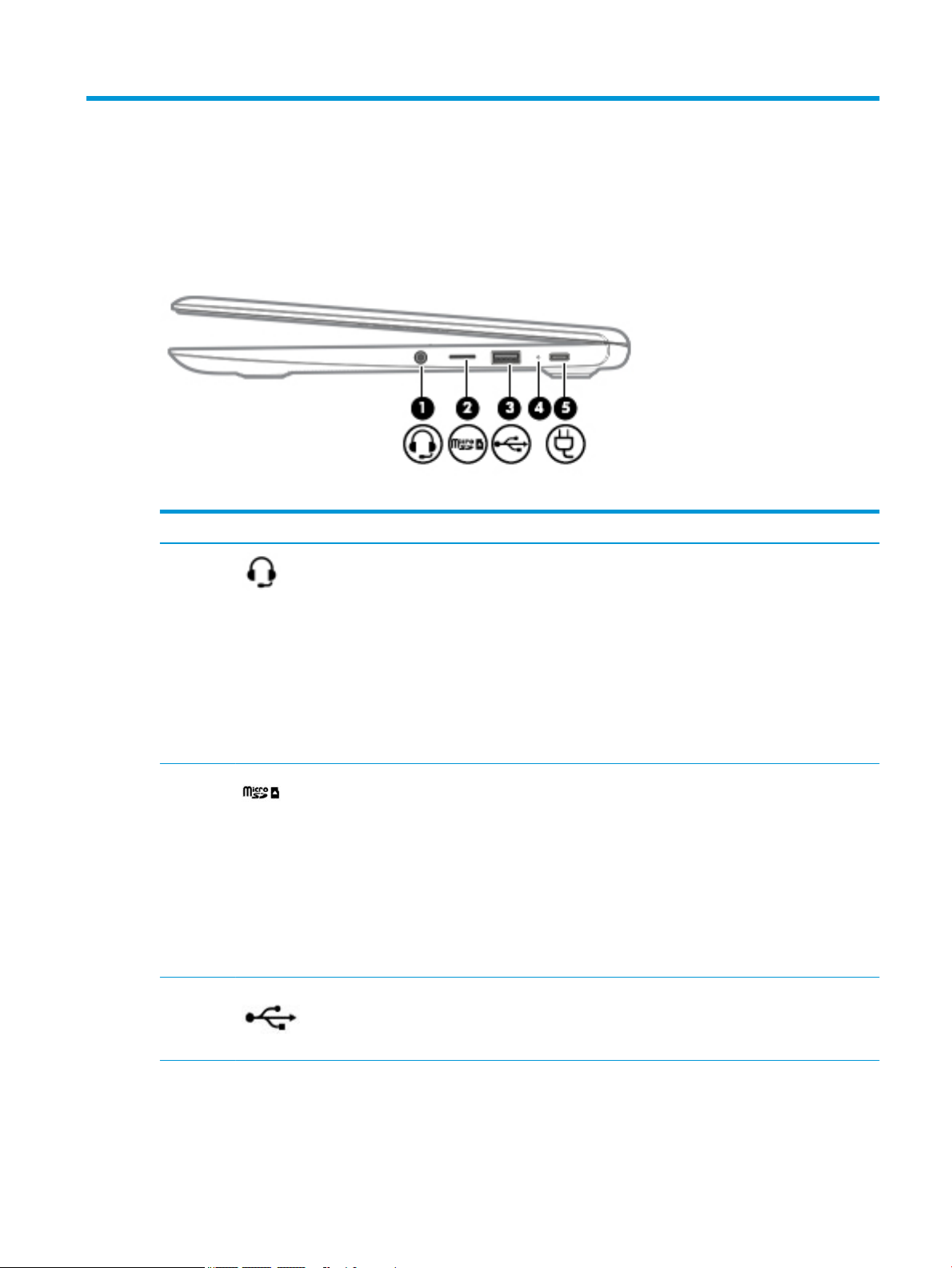
Right side
Table 2-1 Right-side components and their descriptions
Component Description
(1) Audio-out (headphone)/Audio-in
(microphone) combo jack
(2) MicroSD memory card reader Reads optional memory cards that store, manage, share,
(3) USB port Connects a USB device, such as a cell phone, camera,
Connects optional powered stereo speakers, headphones,
earbuds, a headset, or a television audio cable. Also
connects an optional headset microphone. This jack does
not support optional microphone-only devices.
WARNING! To reduce the risk of personal injury, adjust
the volume before putting on headphones, earbuds, or a
headset. For additional safety information, refer to the
Regulatory, Safety, and Environmental Notices.
This guide is provided in the box.
NOTE: When a device is connected to the jack, the
computer speakers are disabled.
or access information.
To insert a card:
1. Hold the card label-side up, with connectors facing
the computer.
2. Insert the card into the memory card reader, and
then press in on the card until it is rmly seated.
To remove a card:
▲ Pull out the card.
activity tracker, or smartwatch, and provides data transfer.
(4) AC adapter and battery light ● White: The AC adapter is connected and the battery is
charged.
● Amber: The AC adapter is connected and the battery
is charging.
Right side 3
Page 10

Table 2-1 Right-side components and their descriptions (continued)
Component Description
● O: The computer is using battery power.
(5) USB Type-C power connector and port Connects an AC adapter that has a USB Type-C connector,
supplying power to the computer and, if needed, charging
the computer battery.
– and –
Connects a USB device that has a Type-C connector, such
as a cell phone, camera, activity tracker, or smartwatch,
and provides data transfer.
– and –
Connects a display device that has a USB Type-C
connector, providing DisplayPort output.
NOTE: Cables and/or adapters (purchased separately)
may be required.
4 Chapter 2 Getting to know your computer
Page 11
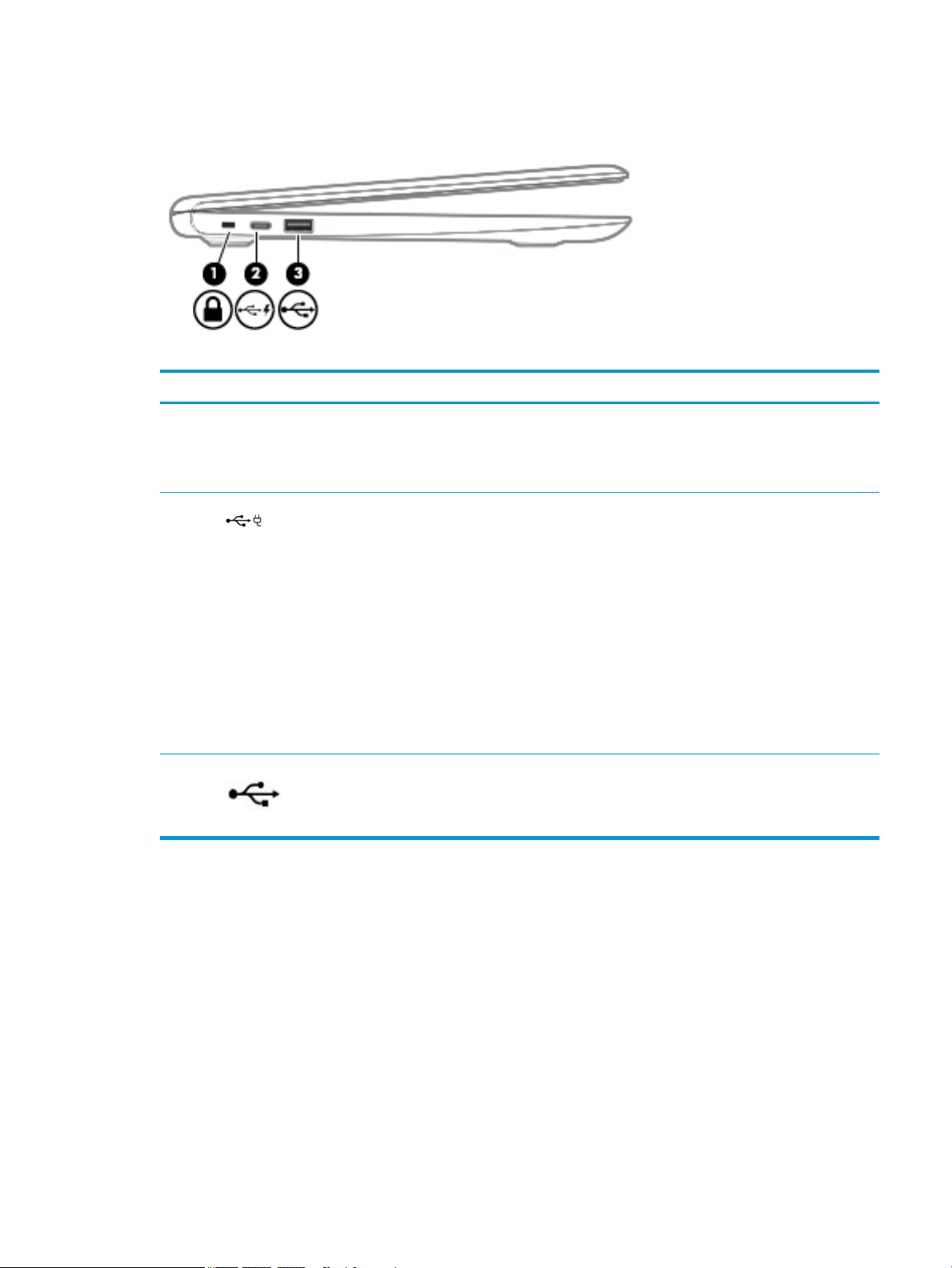
Left side
Table 2-2 Left-side components and their descriptions
Component Description
(1) Nano security cable slot Attaches an optional security cable to the computer.
(2) USB Type-C power connector and port Connects an AC adapter that has a USB Type-C connector,
NOTE: The security cable is designed to act as a
deterrent, but it may not prevent the computer from being
mishandled or stolen.
supplying power to the computer and, if needed, charging
the computer battery.
– and –
Connects a USB device that has a Type-C connector, such as
a cell phone, camera, activity tracker, or smartwatch, and
provides data transfer.
– and –
Connects a display device that has a USB Type-C connector,
providing DisplayPort output.
NOTE: Cables and/or adapters (purchased separately)
may be required.
(3) USB port Connects a USB device, such as a cell phone, camera,
activity tracker, or smartwatch, and provides data transfer.
Left side 5
Page 12
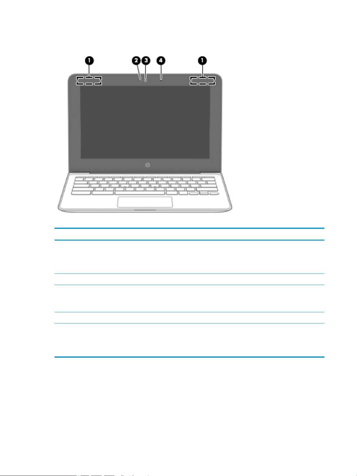
Display
Table 2-3 Display components and their descriptions
Component Description
(1) WLAN antennas* Send and receive wireless signals to communicate with wireless
local area networks (WLANs).
NOTE: The position of the WLAN antennas may dier,
depending on the product.
(2) Camera light On: The camera is in use.
(3) Camera Allows you to video chat, record video, and record still images.
NOTE: Camera functions vary depending on the camera
hardware and software installed on your product.
(4) Internal microphone Records sound.
*The antennas are not visible from the outside of the computer, and antenna location varies. For optimal transmission, keep the areas
immediately around the antennas free from obstructions.
For wireless regulatory notices, see the section of the Regulatory, Safety, and Environmental Notices that applies to your country or
region.
6 Chapter 2 Getting to know your computer
Page 13
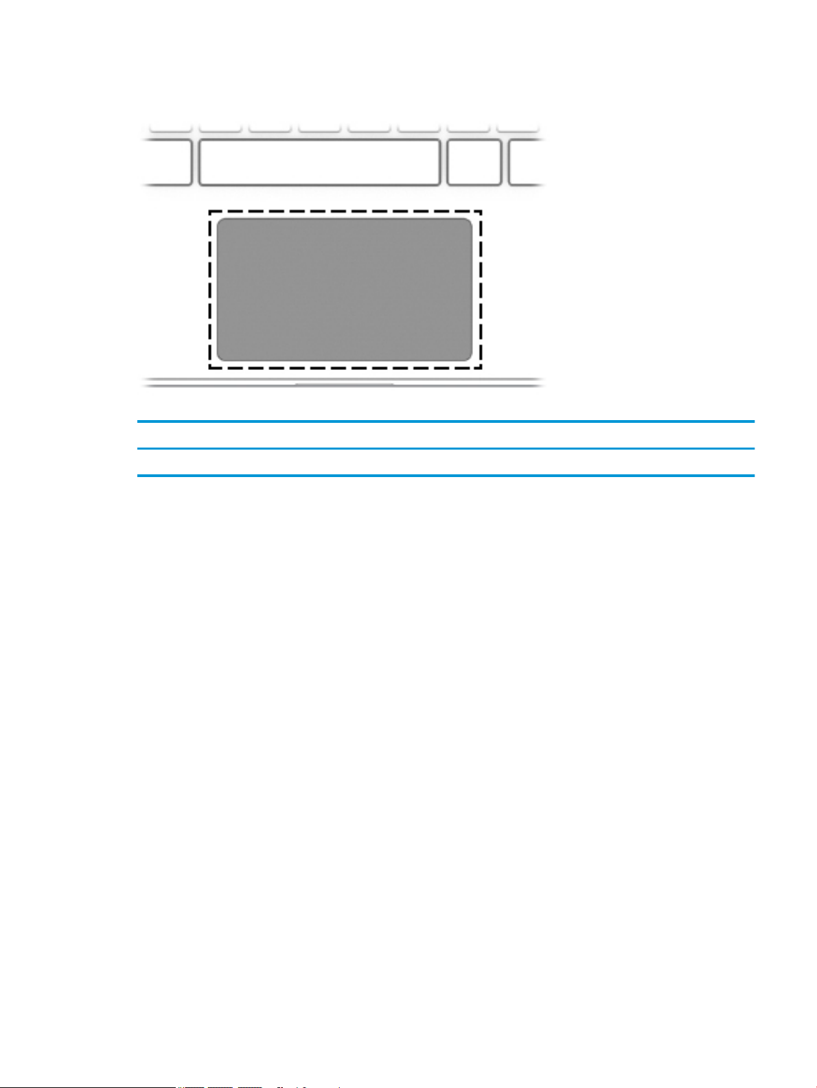
TouchPad
Table 2-4 TouchPad components and their descriptions
Component Description
TouchPad zone Moves the on-screen pointer and selects or activates items on the screen.
TouchPad 7
Page 14
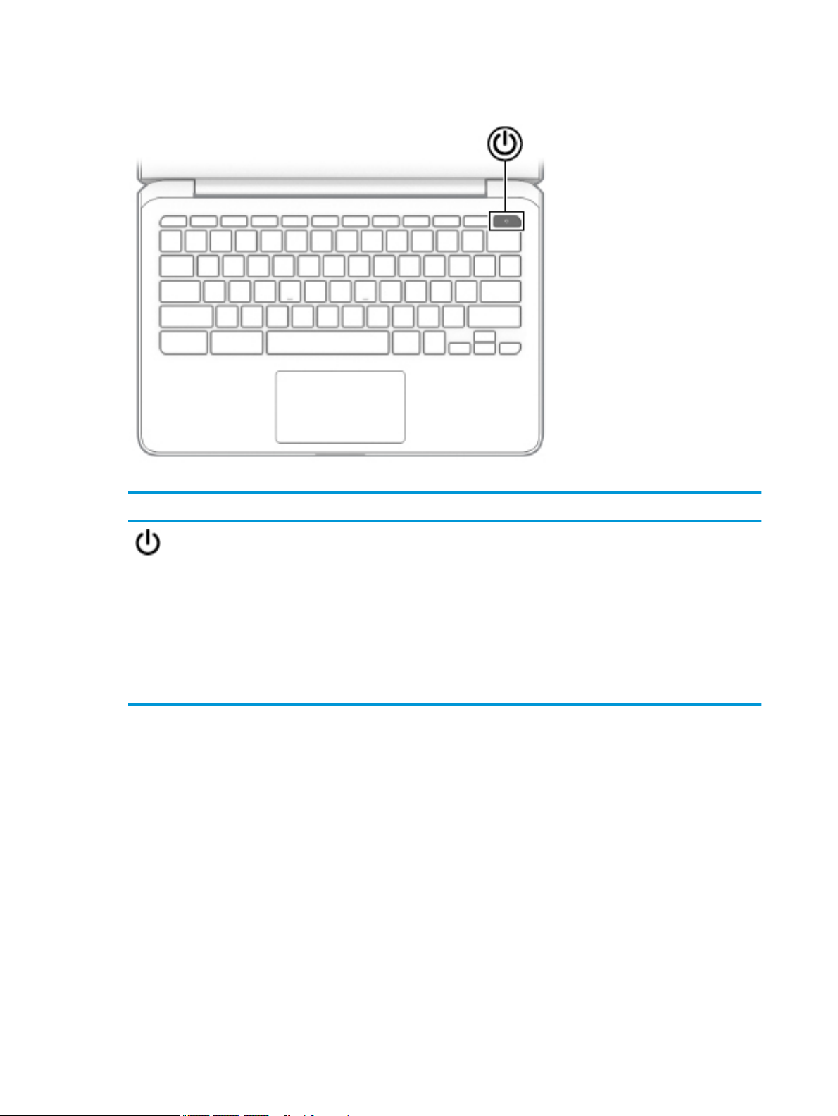
Button
Table 2-5 Button and its description
Component Description
Power button ● When the computer is o, press the button to turn on the
computer.
● When the computer is in the Sleep state, press the button
briey to exit Sleep.
● When the computer is on and you want to lock the screen, press
the button until you see the sign-in screen appear. Pressing the
power button during screen-lock mode turns o the computer.
● When the computer is on and you want to turn it o, press and
hold the button to lock the screen, and then continue to press
the button until the computer turns o.
8 Chapter 2 Getting to know your computer
Page 15
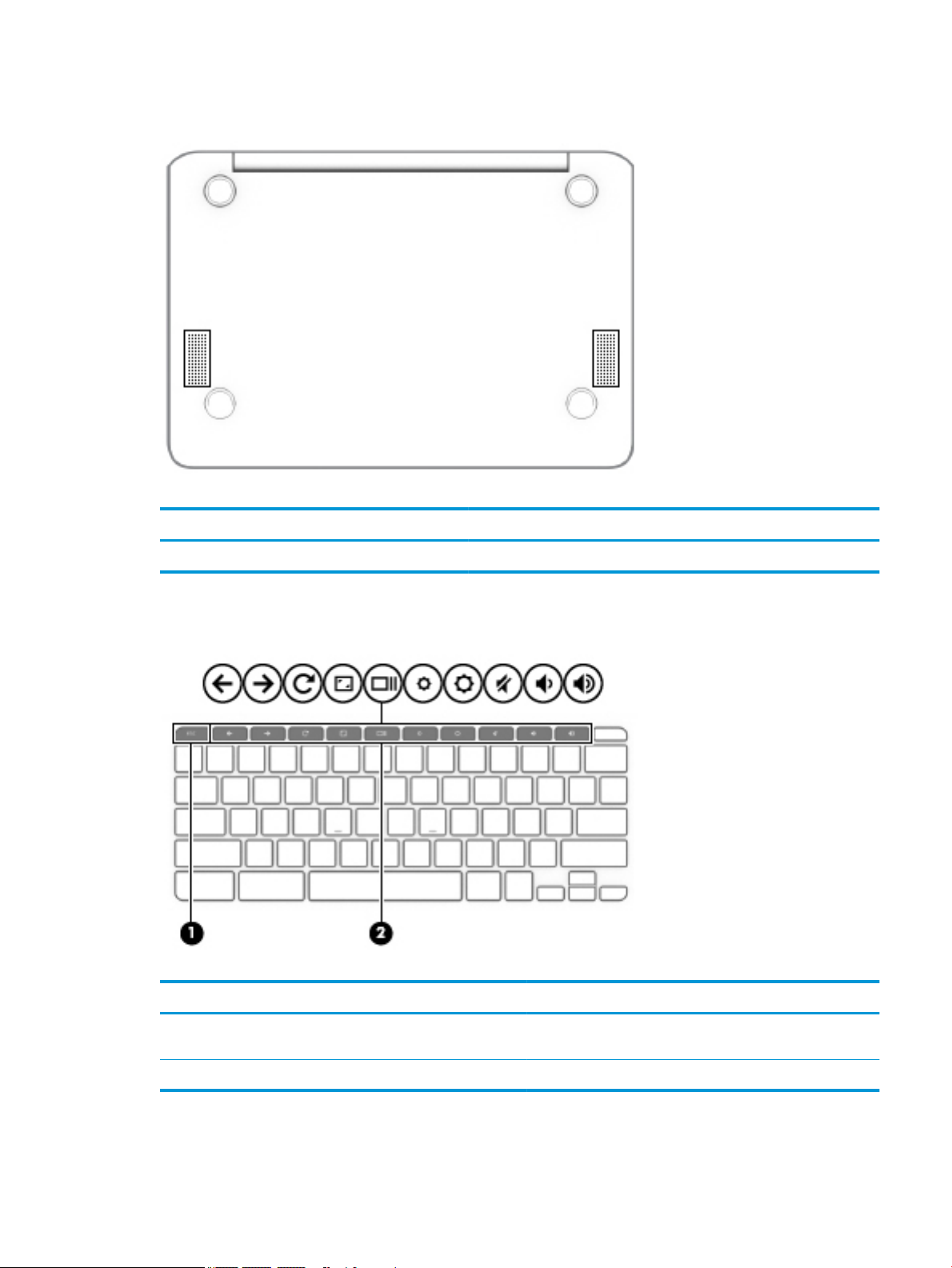
Bottom
Table 2-6 Right-side component and its descriptions
Component Description
Speakers (2) Produce sound.
Special keys
Table
2-7 Special keys and their descriptions
Component Description
(1) esc key Activates certain computer functions when pressed in
(2) Action keys Execute frequently used system functions.
combination with other keys, such as Tab or Shift.
Bottom 9
Page 16
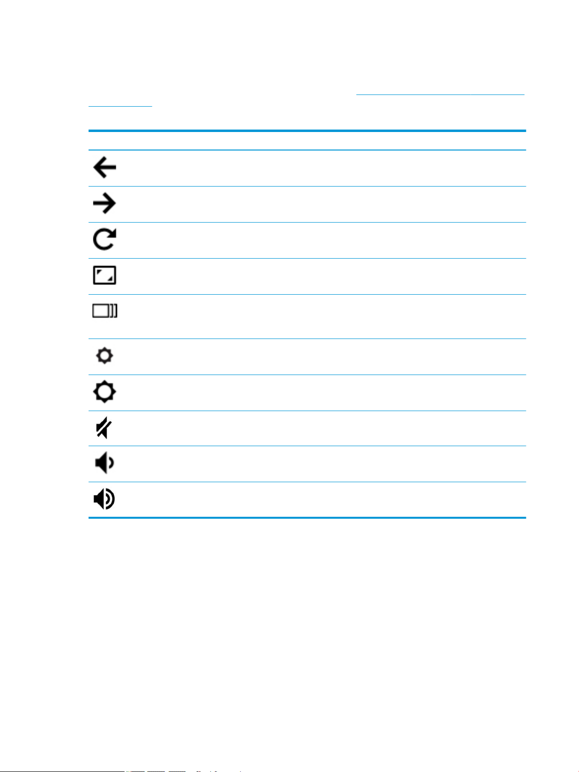
Action keys
For more information on action keys and keyboard shortcuts, go to https://support.google.com/chromebook/
answer/183101. Select your language at the bottom of the page.
Table 2-8 Action keys and their descriptions
Icon Key Description
Back Displays the previous page in your browser history.
Forward Displays the next page in your browser history.
Reload Reloads your current page.
Full screen Opens your page in full-screen mode.
Display apps Displays open apps.
NOTE: Pressing this button in conjunction with ctrl takes a
screenshot.
Brightness down Decreases the screen brightness incrementally as long as you hold
down the key.
Brightness up Increases the screen brightness incrementally as long as you hold
down the key.
Mute Mutes speaker sound.
Volume down Decreases speaker volume incrementally as long as you hold down the
key.
Volume up Increases speaker volume incrementally as long as you hold down the
key.
10 Chapter 2 Getting to know your computer
Page 17
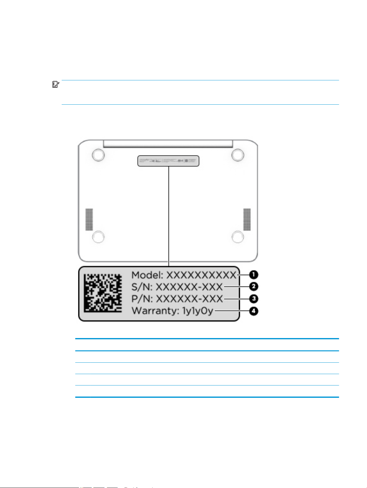
Labels
The labels axed to the computer provide information you may need when you troubleshoot system
problems or travel internationally with the computer. Labels may be in paper form or imprinted on the
product.
IMPORTANT: Check the following locations for the labels described in this section: the bottom of the
computer, inside the battery bay, under the service door, on the back of the display, or on the bottom of a
tablet kickstand.
● Service label—Provides important information to identify your computer. When contacting support, you
may be asked for the serial number, the product number, or the model number. Locate this information
before you contact support.
Table 2-9 Service label components
Component
(1) Model number
(2) Serial number
(3) Part number
(4) Warranty period
● Regulatory label(s)—Provide(s) regulatory information about the computer.
● Wireless certication label(s)—Provide(s) information about optional wireless devices and the approval
markings for the countries or regions in which the devices have been approved for use.
Labels 11
Page 18
3 Illustrated parts catalog
NOTE: HP continually improves and changes product parts. For complete and current information on
supported parts for your computer, go to http://partsurfer.hp.com, select your country or region, and then
follow the on-screen instructions.
Computer components
12 Chapter 3 Illustrated parts catalog
Page 19

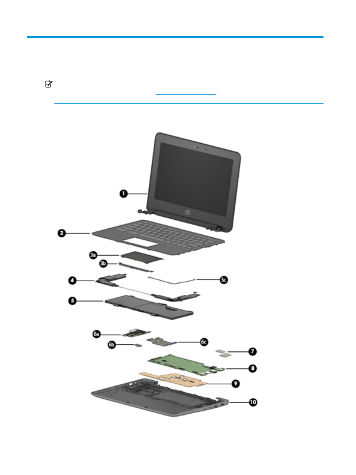
Table 3-1 Computer major components and their descriptions
Item Component Spare part number
(1) 11.6 in. display assembly
The display assembly is spared at the subcomponent level only. For more display assembly spare part information, see
Display assembly subcomponents on page 14.
(2) Keyboard/top cover (includes keyboard cable):
NOTE: For a detailed list of keyboard country codes, see Keyboard/top cover on page 23.
(3a) TouchPad (does not include cable) L51914-001
(3b) TouchPad bracket L18300-001
(3c) TouchPad cable (included in the Cable Kit, spare part number L14906-001, and includes double-sided adhesive)
(4) Speakers (include cables) L14920-001
(5) Battery (2-cell, 47 Whr, Li-ion, includes cable) 917725-855
Battery connector tape (not illustrated) L14905-001
(6a) USB port board (does not include cable) L14923-001
(6b) USB port board bracket L14359-001
(6c) USB port board cable (included in the Cable Kit, spare part number L14906-001, and includes double-sided adhesive)
(7) System board thermal pads L48489-001
(8) System board (includes processor, system memory, eMMC storage, the Google Chrome operating system, and
replacement thermal material)
Equipped with an AMD A4-9120 processor, 4 GB of system memory, and 32 GB of eMMC
storage
Equipped with an AMD A4-9120 processor, 4 GB of system memory, and 16 GB of eMMC
storage
L52192-xx1
L51911-001
L51910-001
(9) Heat sink (includes replacement thermal material) L46576-001
(10) Bottom cover
In black nish L51913-001
In delicate orange nish L51912-001
WLAN module (Qualcomm Atheros QCA6174A-5ac 2 × 2 + Bluetooth 4.2; not illustrated) L54597-001
Rubber Foot Kit (includes bottom cover feet; not illustrated) L20220-001
Computer components 13
Page 20

Display assembly subcomponents
Table 3-2 Display components and their descriptions
Item Component Spare part number
(1) Display bezel L14912-001
(2) Webcam/microphone module (includes double-sided adhesive) L51916-001
(3) Display panel bracket L14913-001
(4) Display panel (does not include display panel cable)
Anti glare, SVA, non-touch L51917-001
Anti glare, UWVA, non-touch L51918-001
BrightView, UWVA, touch L51919-001
(5) Display panel cable
14 Chapter 3 Illustrated parts catalog
Page 21

Table 3-2 Display components and their descriptions (continued)
Item Component Spare part number
For use only on computer models equipped with a touch display assembly L14915-001
For use only on computer models equipped with a non-touch display assembly L14914-001
(6) Display hinges (2) L14907-001
(7) Wireless antennas L52273-001
(8) Display back cover (includes the webcam/microphone module cable and wireless antenna cables and transceivers)
In chalkboard gray nish L14908-001
In delicate orange nish L14911-001
Miscellaneous parts
Table 3-3 Miscellaneous parts and their descriptions
Component Spare part number
AC adapters
90 W AC adapter (PFC, 4.5 mm) 710413-001
45 W AC adapter (non-PFC, USB Type-C, 3-pin) 934739-850
45 W AC adapter (non-PFC, USB-C, 1.8 m, 3 pin) L43407-001
Screw Kit L14919-001
Cable Kit (includes TouchPad cable and USB port board cable) L14906-001
HP Comfort Grip Wireless Mouse 691922-001
HP USB Travel Mouse 757770-001
HP stereo 3.5 mm headset 840339-001
Essential backpack 679923-001
HP USB-C Dock G4 L16133-001
Kensington Nano Lock 918431-001
Adapters
USB-C–to–USB 3.0 adapter 814618-001
USB-C–to–DisplayPort adapter 831753-001
USB-C–to–RJ-45 adapter 855560-001
USB-C–to–HDMI 2.0 adapter 935325-001
Power cord (C5 connector, 1.8-m)
For use in North America L19367-002
Power cord (C5 connector, 1.0-m)
For use in Argentina L19357-001
For use in Australia L19358-001
Miscellaneous parts 15
Page 22

Table 3-3 Miscellaneous parts and their descriptions (continued)
Component Spare part number
213356-008
For use in Brazil L19359-001
438722-004
For use in Denmark L19360-001
For use in Europe L19361-001
213350-009
For use in India L19363-001
404827-003
For use in Israel L19362-001
398063-003
For use in Italy L19364-001
213352-008
For use in North America L19367-001
213349-009
For use in the People’s Republic of China L19368-001
286497-008
For use in South Africa L19369-001
361240-002
For use in South Korea L19366-001
267836-008
For use in Switzerland L19370-001
213354-008
For use in Taiwan L19372-001
393313-003
For use in Thailand L19371-001
For use in the United Kingdom L19373-001
213351-008
16 Chapter 3 Illustrated parts catalog
Page 23

4 Removal and replacement procedures
preliminary requirements
Tools required
You will need the following tools to complete the removal and replacement procedures:
● Non-marking, non-conductive pry tool
● Magnetic Phillips P1 screwdriver
Service considerations
The following sections include some of the considerations that you must keep in mind during disassembly
and assembly procedures.
NOTE: As you remove each subassembly from the computer, place the subassembly (and all accompanying
screws) away from the work area to prevent damage.
Plastic parts
IMPORTANT: Using excessive force during disassembly and reassembly can damage plastic parts.
Cables and connectors
IMPORTANT: When servicing the computer, be sure that cables are placed in their proper locations during
the reassembly process. Improper cable placement can damage the computer.
Cables must be handled with extreme care to avoid damage. Apply only the tension required to unseat or seat
the cables during removal and insertion. Handle cables by the connector whenever possible. In all cases, avoid
bending, twisting, or tearing cables. Be sure that cables are routed in such a way that they cannot be caught
or snagged by parts being removed or replaced. Handle ex cables with extreme care; these cables tear
easily.
Tools required 17
Page 24

Drive handling
IMPORTANT: Drives are fragile components that must be handled with care. To prevent damage to the
computer, damage to a drive, or loss of information, observe these precautions:
Before removing or inserting a hard drive, shut down the computer. If you are unsure whether the computer is
o or in Hibernation, turn the computer on, and then shut it down through the operating system.
Before handling a drive, be sure that you are discharged of static electricity. While handling a drive, avoid
touching the connector.
Before removing an optical drive, be sure that a disc is not in the drive and be sure that the optical drive tray is
closed.
Handle drives on surfaces covered with at least one inch of shock-proof foam.
Avoid dropping drives from any height onto any surface.
After removing a hard drive or an optical drive, place it in a static-proof bag.
Avoid exposing an internal hard drive to products that have magnetic elds, such as monitors or speakers.
Avoid exposing a drive to temperature extremes or liquids.
If a drive must be mailed, place the drive in a bubble pack mailer or other suitable form of protective
packaging and label the package “FRAGILE.”
Workstation guidelines
Follow these grounding workstation guidelines:
● Cover the workstation with approved static-shielding material.
● Use a wrist strap connected to a properly grounded work surface and use properly grounded tools and
equipment.
● Use conductive eld service tools, such as cutters, screw drivers, and vacuums.
● When xtures must directly contact dissipative surfaces, use xtures made only of static-safe materials.
● Keep the work area free of nonconductive materials, such as ordinary plastic assembly aids and
Styrofoam.
● Handle ESD-sensitive components, parts, and assemblies by the case or PCM laminate. Handle these
items only at static-free workstations.
● Avoid contact with pins, leads, or circuitry.
● Turn o power and input signals before inserting or removing connectors or test equipment.
Electrostatic discharge information
A sudden discharge of static electricity from your nger or other conductor can destroy static-sensitive
devices or microcircuitry. Often the spark is neither felt nor heard, but damage occurs. An electronic device
exposed to electrostatic discharge (ESD) may not appear to be aected at all and can work perfectly
throughout a normal cycle. The device may function normally for a while, but it has been degraded in the
internal layers, reducing its life expectancy.
Networks built into many integrated circuits provide some protection, but in many cases, the discharge
contains enough power to alter device parameters or melt silicon junctions.
18 Chapter 4 Removal and replacement procedures preliminary requirements
Page 25

IMPORTANT: To prevent damage to the device when you are removing or installing internal components,
observe these precautions:
Keep components in their electrostatic-safe containers until you are ready to install them.
Before touching an electronic component, discharge static electricity by using the guidelines described in this
section.
Avoid touching pins, leads, and circuitry. Handle electronic components as little as possible.
If you remove a component, place it in an electrostatic-safe container.
Generating static electricity
Note the following:
● Dierent activities generate dierent amounts of static electricity.
● Static electricity increases as humidity decreases.
Table 4-1 Static electricity occurrence based on activity and humidity
Relative humidity
Event 55% 40% 10%
Walking across carpet
Walking across vinyl oor
Motions of bench worker
Removing DIPs from plastic tube
Removing DIPs from vinyl tray
Removing DIPs from Styrofoam
Removing bubble pack from PCB
Packing PCBs in foam-lined box
Electronic components are then multi-packaged inside plastic tubes, trays, or Styrofoam.
NOTE: As little as 700 volts can degrade a product.
Preventing electrostatic damage to equipment
Many electronic components are sensitive to ESD. Circuitry design and structure determine the degree of
sensitivity. The following packaging and grounding precautions are necessary to prevent static electricity
damage to electronic components.
● To avoid hand contact, transport products in static-safe containers such as tubes, bags, or boxes.
7,500 V
3,000 V
400 V
400 V
2,000 V
3,500 V
7,000 V
5,000 V
15,000 V
5,000 V
800 V
700 V
4,000 V
5,000 V
20,000 V
11,000 V
35,000 V
12,000 V
6,000 V
2,000 V
11,500 V
14,500 V
26,500 V
21,000 V
● Protect all electrostatic parts and assemblies with conductive or approved containers or packaging.
● Keep electrostatic-sensitive parts in their containers until they arrive at static-free stations.
● Place items on a grounded surface before removing them from their container.
● Always be properly grounded when touching a sensitive component or assembly.
Electrostatic discharge information 19
Page 26

● Avoid contact with pins, leads, or circuitry.
● Place reusable electrostatic-sensitive parts from assemblies in protective packaging or conductive
foam.
Personal grounding methods and equipment
Use the following equipment to prevent static electricity damage to electronic components:
● Wrist straps are exible straps with a maximum of one-megohm ± 10% resistance in the ground cords.
To provide proper ground, a strap must be worn snug against bare skin. The ground cord must be
connected and t snugly into the banana plug connector on the grounding mat or workstation.
● Heel straps/Toe straps/Boot straps can be used at standing workstations and are compatible with
most types of shoes or boots. On conductive oors or dissipative oor mats, use them on both feet with
a maximum of one-megohm ± 10% resistance between the operator and ground.
Table 4-2 Static shielding protection levels
Static shielding protection levels
Method Voltage
Antistatic plastic
Carbon-loaded plastic
Metallized laminate
Grounding the work area
To prevent static damage at the work area, use the following precautions:
● Cover the work surface with approved static-dissipative material. Provide a wrist strap connected to the
work surface and properly grounded tools and equipment.
● Use static-dissipative mats, foot straps, or air ionizers to give added protection.
● Handle electrostatic sensitive components, parts, and assemblies by the case or PCB laminate. Handle
them only at static-free work areas.
● Turn o power and input signals before inserting and removing connectors or test equipment.
● Use xtures made of static-safe materials when xtures must directly contact dissipative surfaces.
● Keep work area free of nonconductive materials such as ordinary plastic assembly aids and Styrofoam.
● Use eld service tools, such as cutters, screwdrivers, and vacuums, that are conductive.
Recommended materials and equipment
1,500
7,500
15,000
Materials and equipment that are recommended for use in preventing static electricity include:
● Antistatic tape
● Antistatic smocks, aprons, or sleeve protectors
● Conductive bins and other assembly or soldering aids
● Conductive foam
● Conductive tabletop workstations with ground cord of one-megohm +/- 10% resistance
● Static-dissipative table or oor mats with hard tie to ground
20 Chapter 4 Removal and replacement procedures preliminary requirements
Page 27

● Field service kits
● Static awareness labels
● Wrist straps and footwear straps providing one-megohm +/- 10% resistance
● Material handling packages
● Conductive plastic bags
● Conductive plastic tubes
● Conductive tote boxes
● Opaque shielding bags
● Transparent metallized shielding bags
● Transparent shielding tubes
Packaging and transporting guidelines
Follow these grounding guidelines when packaging and transporting equipment:
● To avoid hand contact, transport products in static-safe tubes, bags, or boxes.
● Protect ESD-sensitive parts and assemblies with conductive or approved containers or packaging.
● Keep ESD-sensitive parts in their containers until the parts arrive at static-free workstations.
● Place items on a grounded surface before removing items from their containers.
● Always be properly grounded when touching a component or assembly.
● Store reusable ESD-sensitive parts from assemblies in protective packaging or nonconductive foam.
● Use transporters and conveyors made of antistatic belts and roller bushings. Be sure that mechanized
equipment used for moving materials is wired to ground and that proper materials are selected to avoid
static charging. When grounding is not possible, use an ionizer to dissipate electric charges.
Packaging and transporting guidelines 21
Page 28

5 Removal and replacement procedures for
authorized service provider parts
IMPORTANT: Components described in this chapter should be accessed only by an authorized service
provider. Accessing these parts can damage the computer or void the warranty.
IMPORTANT: This computer does not have user-replaceable parts. Only HP authorized service providers
should perform the removal and replacement procedures described here. Accessing an internal part could
damage the computer or void the warranty.
Component replacement procedures
NOTE: Details about your computer, including model, serial number, product key, and length of warranty,
are on the service tag at the bottom of your computer. See Labels on page 11 for details.
NOTE: HP continually improves and changes product parts. For complete and current information on
supported parts for your computer, go to http://partsurfer.hp.com, select your country or region, and then
follow the on-screen instructions.
There are as many as 45 screws that must be removed, replaced, and/or loosened when servicing the parts
described in this chapter. Make special note of each screw size and location during removal and replacement.
Preparation for disassembly
See Removal and replacement procedures preliminary requirements on page 17 for initial safety procedures.
1. Turn o the computer. If you are unsure whether the computer is o or in Hibernation, turn the
computer on, and then shut it down through the operating system.
2. Disconnect the power from the computer by unplugging the power cord from the computer.
3. Disconnect all external devices from the computer.
22 Chapter 5 Removal and replacement procedures for authorized service provider parts
Page 29

Keyboard/top cover
NOTE: All keyboard/top cover spare part kits include the keyboard cable.
Table 5-1 Keyboard/top cover description and part number
For use in country/region Spare part number For use in country/region Spare part number
For use in Belgium L52192-A41 For use in Romania L52192-271
For use in Brazil L52192-201 For use in Russia L52192-251
For use in Canada L52192-DB1 For use in Saudi Arabia L52192-171
For use in the Czech Republic
and Slovakia
For use in Denmark, Finland,
and Norway
For use in France L52192-051 For use in Switzerland L52192-BG1
For use in Germany L52192-041 For use in Taiwan L52192-AB1
For use in Israel L52192-BB1 For use in Thailand L52192-281
For use in Italy L52192-061 For use in Turkey L52192-141
For use in Latin America L52192-161 For use in the United Kingdom L52192-031
For use in the Netherlands L52192-B31 For use in the United States L52192-001
For use in Portugal L52192-131
L52192-FL1 For use in South Korea L52192-AD1
L52192-DH1 For use in Spain L52192-071
Before disassembling the computer, follow these steps:
▲ Prepare the computer for disassembly (Preparation for disassembly on page 22).
Remove the bottom cover:
1. Position the computer upside down.
2. Remove the two Phillips M2.5 × 8.7 screws (1) that secure the bottom cover to the computer.
Component replacement procedures 23
Page 30

3. Remove the six Phillips M2.5 × 6.6 screws (2) that secure the bottom cover to the computer.
4. Open the computer.
5. Use a non-marking, non-conductive pry tool (1) to separate the front edge of the keyboard/top cover (2)
from the bottom cover.
6. Release the zero insertion force (ZIF) connector (3) to which the keyboard cable is connected, and then
disconnect the keyboard cable from the system board.
7. Release the ZIF connector (4) to which the TouchPad cable is connected, and then disconnect the
TouchPad cable from the system board.
24 Chapter 5 Removal and replacement procedures for authorized service provider parts
Page 31
8. Remove the keyboard/top cover (5).
Reverse this procedure to install the keyboard/top cover.
Component replacement procedures 25
Page 32

TouchPad cable
NOTE: The TouchPad spare part kit does not includes the TouchPad cable. The TouchPad cable is included in
the Cable Kit, spare part number L14906-001, and includes double-sided adhesive.
Before removing the TouchPad cable, follow these steps:
1. Prepare the computer for disassembly (Preparation for disassembly on page 22).
2. Remove the keyboard/top cover (see Keyboard/top cover on page 23).
Remove the TouchPad cable:
1. Detach the TouchPad cable (1) from the keyboard/top cover.
2. Release the ZIF connector (2) to which TouchPad cable is connected, and then disconnect the TouchPad
cable from the TouchPad.
3. Remove the TouchPad cable.
Reverse this procedure to install the TouchPad cable.
26 Chapter 5 Removal and replacement procedures for authorized service provider parts
Page 33

TouchPad
NOTE: The TouchPad spare part kit does not include the TouchPad cable. The TouchPad cable is included in
the Cable Kit, spare part number L14906-001, and includes double-sided adhesive.
Table 5-2 TouchPad description and part number
Before removing the TouchPad, follow these steps:
1. Prepare the computer for disassembly (Preparation for disassembly on page 22).
2. Remove the keyboard/top cover (see Keyboard/top cover on page 23).
Remove the TouchPad:
1. Disconnect the cable from the TouchPad ZIF connector (TouchPad cable on page 26).
2. Release the shielding material (1) that covers the top edge of the TouchPad.
3. Remove the three Phillips M2.0 × 2.5 screws (2) that secure the TouchPad and TouchPad bracket to the
4. Remove the three Phillips M2.0 × 2.0 broadhead screws (3) that secure the TouchPad to the
Description Spare part number
TouchPad L51914-001
keyboard/top cover.
keyboard/top cover.
5. Remove the TouchPad bracket (4).
The TouchPad bracket is available using spare part number L18300-001.
6. Remove the TouchPad (5).
Reverse this procedure to install the TouchPad.
Component replacement procedures 27
Page 34

Battery
Table 5-3 Battery description and part number
Description Spare part number
2 cell, 47 Whr, Li-ion battery (includes cable) 917725-855
Before removing the battery, follow these steps:
1. Prepare the computer for disassembly (Preparation for disassembly on page 22).
2. Remove the keyboard/top cover (see Keyboard/top cover on page 23).
Remove the battery:
1. Release the tape (1) that secures the battery cable connector to the system board.
The battery connector tape is available using spare part number L14905-001.
2. Disconnect the battery cable from the system board (2).
3. Remove the two Phillips M2.0 × 3.5 screws (1) that secure the battery to the bottom cover.
28 Chapter 5 Removal and replacement procedures for authorized service provider parts
Page 35

4. Remove the battery (2).
Reverse this procedure to install the battery.
Component replacement procedures 29
Page 36

WLAN module
Table 5-4 WLAN module description and part number
Description Spare part number
Qualcomm Atheros QCA6174A-5ac 2 × 2 + Bluetooth 4.2 L54597-001
CAUTION: To prevent an unresponsive system, replace the wireless module only with a wireless module
authorized for use in the computer by the governmental agency that regulates wireless devices in your
country or region. If you replace the module and then receive a warning message, remove the module to
restore device functionality, and then contact technical support.
Before removing the WLAN module, follow these steps:
1. Prepare the computer for disassembly (Preparation for disassembly on page 22).
2. Remove the keyboard/top cover (see Keyboard/top cover on page 23).
3. Disconnect the battery (see Battery on page 28).
Remove the WLAN module:
1. Disconnect the wireless antenna cables (1) from the terminals on the WLAN module.
NOTE: The wireless antenna cable labeled “1/MAIN” connects to the WLAN module “Main” terminal.
The wireless antenna cable labeled “2/AUX” connects to the WLAN module “Aux” terminal.
2. Remove the Phillips M2.0 × 2.5 screw (2) that secures the WLAN module to the computer. (The WLAN
module tilts up.)
3. Remove the WLAN module (3) by pulling the module away from the slot at an angle.
30 Chapter 5 Removal and replacement procedures for authorized service provider parts
Page 37

NOTE: If the wireless antenna cables are not connected to the WLAN module terminal, the protective
sleeves should be installed on the antenna connectors, as shown in the following illustration.
Reverse this procedure to install the WLAN module.
Component replacement procedures 31
Page 38

Speakers
Table 5-5 Speaker description and part number
Before removing the speakers, follow these steps:
1. Prepare the computer for disassembly (Preparation for disassembly on page 22).
2. Remove the keyboard/top cover (see Keyboard/top cover on page 23).
3. Disconnect the battery cable from the system board (see Battery on page 28).
Remove the speakers:
1. If a protective tab covers the connector, lift the tab.
2. Disconnect the speaker cable (1) from the system board.
3. Release the speaker cable (2) from the retention channel/retention clips built into the bottom cover.
4. Remove the two Phillips M2.0 × 3.5 screws (3) that secure the speakers to the bottom cover.
5. Remove the speakers (4).
Description Spare part number
Speaker (include cables) L14920-001
Reverse this procedure to install the speakers.
32 Chapter 5 Removal and replacement procedures for authorized service provider parts
Page 39

USB port board cable
NOTE: The USB port board spare part kit does not includes the USB port board cable. The USB port board
cable is included in the Cable Kit, spare part number L14906-001, and includes double-sided adhesive.
Before removing the USB port board cable, follow these steps:
1. Prepare the computer for disassembly (Preparation for disassembly on page 22).
2. Remove the keyboard/top cover (see Keyboard/top cover on page 23).
3. Disconnect the battery cable from the system board (see Battery on page 28).
Remove the USB port board cables:
1. If a protective tab covers the connectors, lift the tab.
2. Release the two reverse ZIF connectors (1) to which the USB port board cables are connected, and then
disconnect the USB port board cables from the USB port board.
3. Release the two reverse ZIF connectors (2) to which the USB port board cables are connected, and then
disconnect the USB port board cables from the system board.
4. Remove the USB port board cables (3).
Reverse this procedure to install the USB port board cable.
Component replacement procedures 33
Page 40

USB port board
NOTE: The USB port board spare part kit does not include the USB port board cable. The USB port board
cable is included in the Cable Kit, spare part number L14906-001.
Table 5-6 USB port board description and part number
Description Spare part number
USB port board L14923-001
Before removing the USB port board, follow these steps:
1. Prepare the computer for disassembly (Preparation for disassembly on page 22).
2. Remove the keyboard/top cover (see Keyboard/top cover on page 23).
3. Disconnect the battery cable from the system board (see Battery on page 28).
4. Remove the left speaker (see Speakers on page 32).
Remove the USB port board:
1. If a protective tab covers the connectors, lift the tab.
2. Release the two reverse ZIF connectors (1) to which the USB port board cables are connected, and then
disconnect the USB port board cables from the USB port board.
3. Remove the two Phillips M2.0 × 3.5 screws (2) that secure the USB port board and bracket to the
computer.
4. Remove the USB port board bracket (3).
The USB port board bracket is available using spare part number L14359-001.
5. Remove the USB port board (4).
Reverse this procedure to install the USB port board.
34 Chapter 5 Removal and replacement procedures for authorized service provider parts
Page 41

System board
NOTE: All system board spare part kits include a processor, system memory, eMMC storage, the Google
Chrome operating system, and replacement thermal material.
Table 5-7 System board description and part number
Description Spare part number
System board equipped with an AMD A4-9120 processor, 4 GB of system memory, and 32 GB of eMMC
storage
System board equipped with an AMD A4-9120 processor, 4 GB of system memory, and 16 GB of eMMC
storage
L51911-001
L51910-001
Before removing the system board, follow these steps:
1. Prepare the computer for disassembly (Preparation for disassembly on page 22).
2. Remove the bottom cover (see Keyboard/top cover on page 23).
3. Remove the keyboard/top cover (see Keyboard/top cover on page 23).
4. Disconnect the battery cable from the system board (see Battery on page 28).
5. Remove the WLAN module (see WLAN module on page 30).
When replacing the system board, be sure to remove the heat sink (see Heat sink on page 38) from the
defective system board and install it on the replacement system board.
Remove the system board:
1. If a protective tab covers the connectors, lift the tab.
2. Release the two reverse ZIF connectors (1) to which the USB port board cables are connected, and then
disconnect the USB port board cables from the system board.
3. Disconnect the display webcam/microphone cable (2) from the system board.
4. Release the adhesive strip (3) that secures the display panel cable to the system board.
5. Disconnect the display panel cable (4) from the system board.
Component replacement procedures 35
Page 42
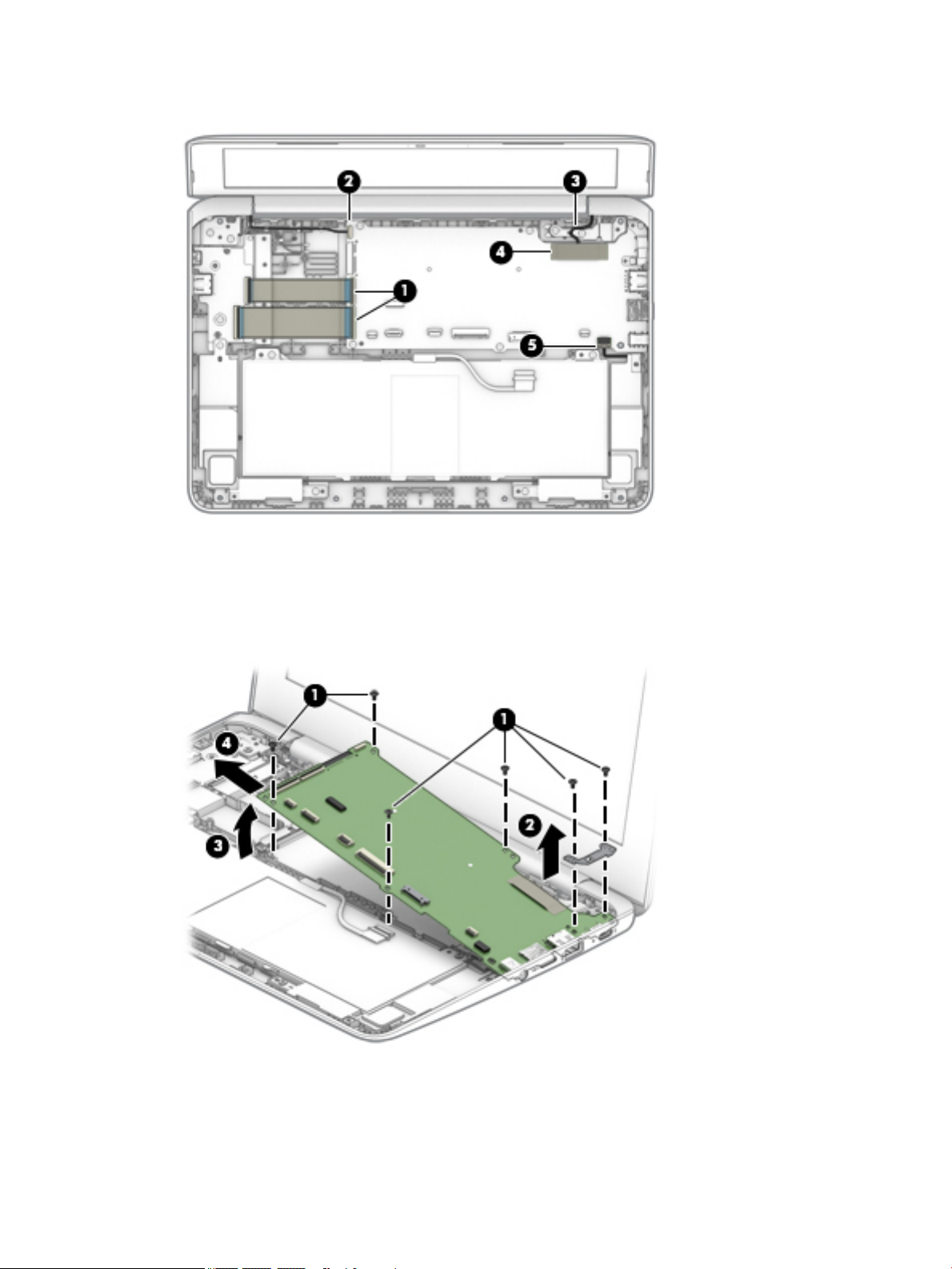
6. Disconnect the speaker cable (5) from the system board.
7. Remove the six Phillips M2.0 × 3.5 screws (1) that secure the system board to the bottom cover.
8. Remove the system board bracket (2).
9. Lift the left edge of the system board (3) until it rests at an angle.
10. Remove the system board (4) by sliding it up and to the left at an angle.
11. Remove the system board.
Reverse this procedure to install the system board.
When installing a system board, install thermal pads in the following locations on the system board:
36 Chapter 5 Removal and replacement procedures for authorized service provider parts
Page 43
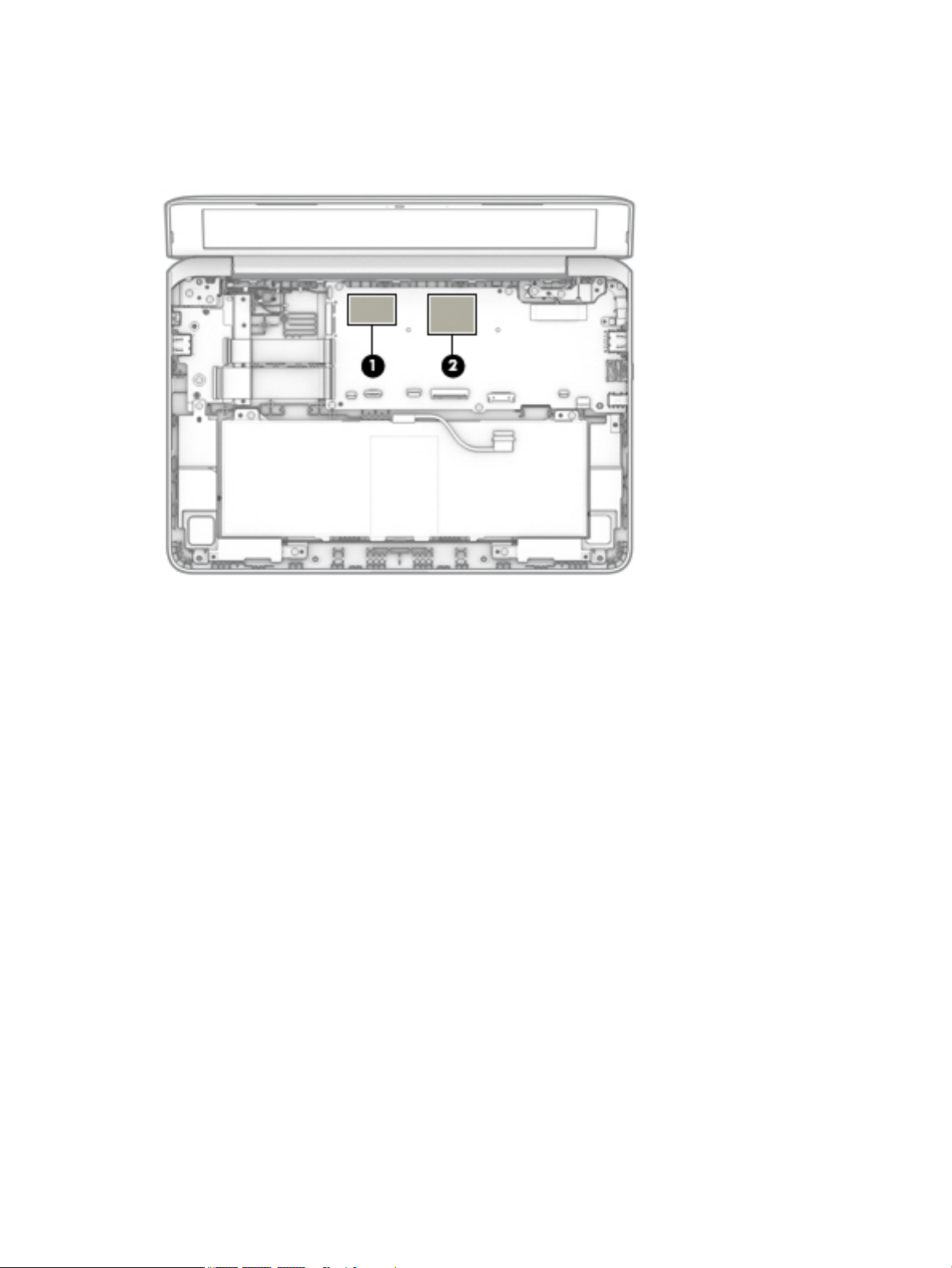
(1) 29 mm × 22 mm
(2) 30 mm × 30 mm
Thermal pads are available using spare part number L48489-001.
Component replacement procedures 37
Page 44

Heat sink
Table 5-8 Heat sink description and part number
Before removing the heat sink, follow these steps:
1. Prepare the computer for disassembly (Preparation for disassembly on page 22).
2. Remove the keyboard/top cover (see Keyboard/top cover on page 23).
3. Disconnect the battery cable from the system board (see Battery on page 28).
4. Remove the system board (see System board on page 35).
Remove the heat sink:
1. Turn the system board upside down with the front toward you.
2. Remove the two Phillips M2.0 × 2.0 broadhead screws (1) that secure the heat sink to the system board.
3. Remove the heat sink (2).
Description Spare part number
Heat sink (includes replacement thermal material) L46576-001
NOTE: The thermal material must be thoroughly cleaned from the surfaces of the heat sink and the system
board components each time the heat sink is removed. Replacement thermal material is included with the
heat sink and system board spare part kits.
Thermal paste is used on the processor (1) and the heat sink section (2) that services it.
38 Chapter 5 Removal and replacement procedures for authorized service provider parts
Page 45

Reverse this procedure to install the heat sink.
Component replacement procedures 39
Page 46

Display assembly
NOTE: The display assembly is spared at the subcomponent level. For display assembly spare part
information, see the individual removal subsections.
Before removing the display assembly, follow these steps:
1. Prepare the computer for disassembly (Preparation for disassembly on page 22).
2. Remove the keyboard/top cover (see Keyboard/top cover on page 23).
3. Disconnect the battery cable from the system board (see Battery on page 28).
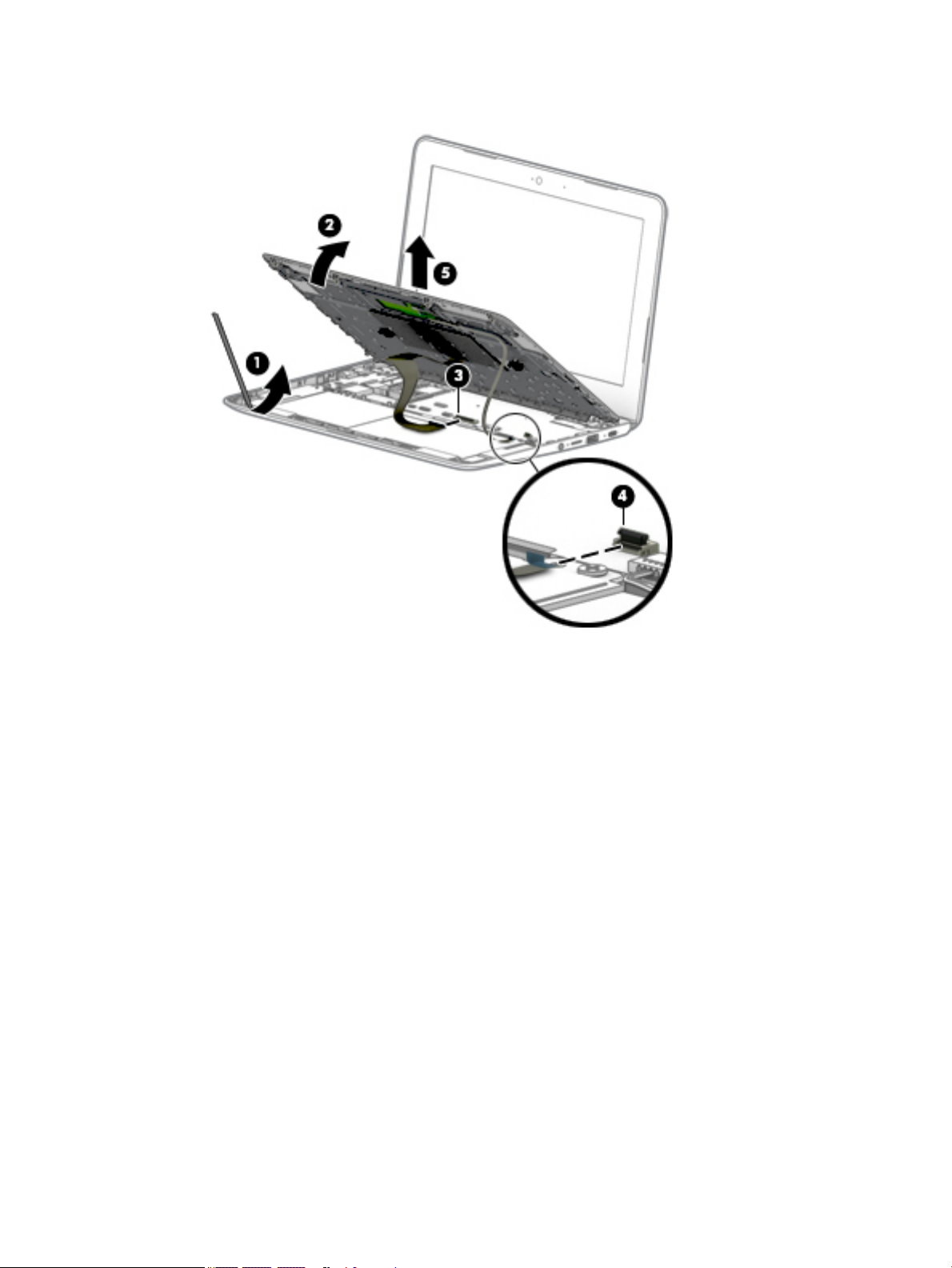
Remove the display assembly:
1. If a protective tab covers the connectors, lift the tab.
2. Disconnect the WLAN antenna cables (1) from the terminals on the WLAN module.
NOTE: The WLAN antenna cable labeled "1/MAIN" connects to the WLAN module "Main" terminal. The
WLAN antenna cable labeled "2/AUX" connects to the WLAN module "Aux" terminal.
3. Disconnect the display webcam/microphone cable (2) from the system board.
4. Release the display webcam/microphone cable from the retention clips (3) and routing channels built
into the bottom cover.
5. Release the adhesive strip (4) that secures the display panel cable to the system board.
6. Disconnect the display panel cable (5) from the system board.
40 Chapter 5 Removal and replacement procedures for authorized service provider parts
Page 47
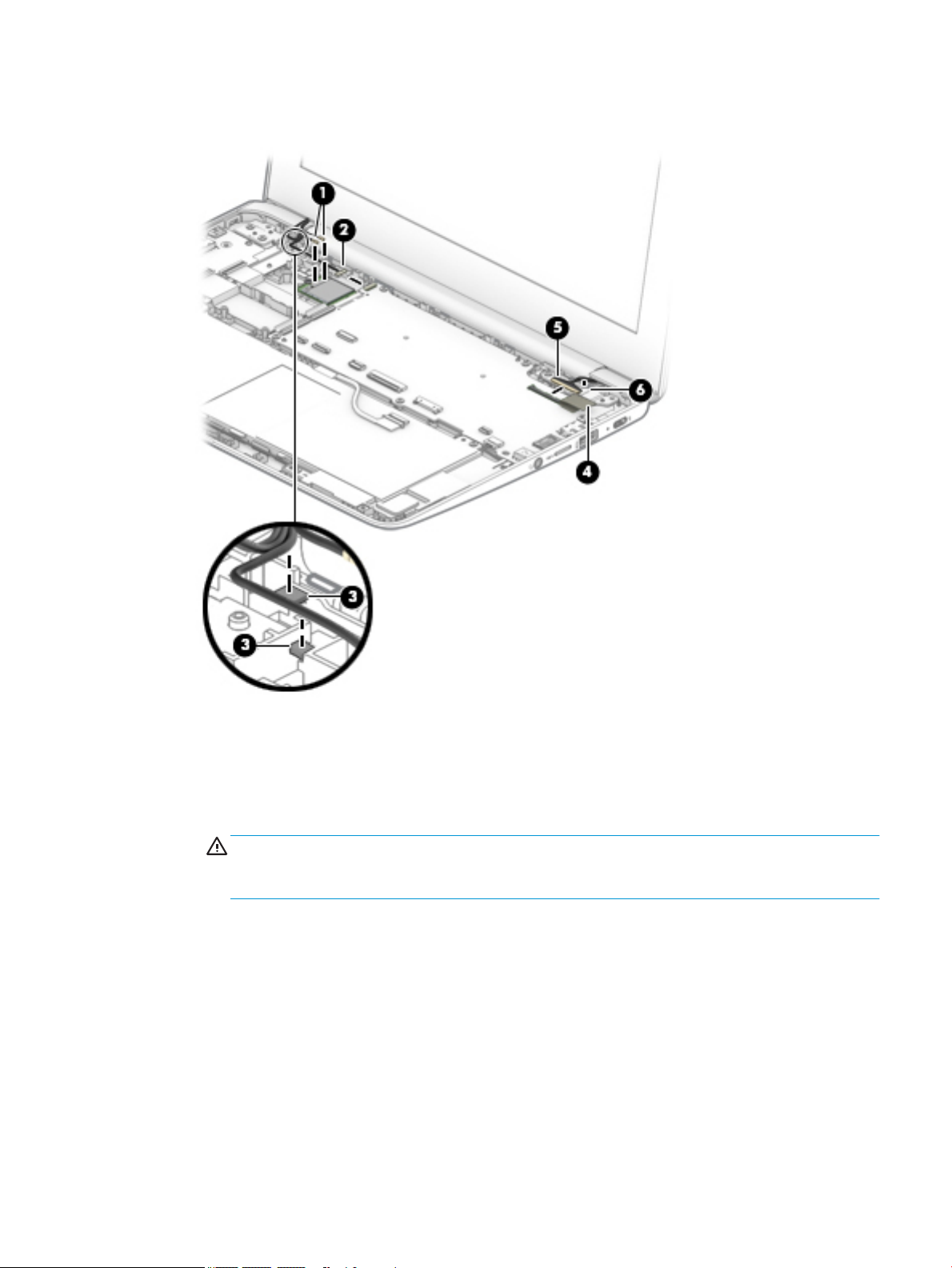
7. Release the display panel cable from the retention clips (6) and routing channels built into the bottom
cover.
8. Open the computer as far as it will open.
9. If it is necessary to replace the display bezel or any of the display assembly subcomponents:
a. Release the top edge of the display bezel (1) from the display assembly.
b. Release the left and right edges of the display bezel (2) from the display assembly.
CAUTION: There is double-sided adhesive (3) on the inside edge of the display bezel bottom
edge. Use caution when releasing the display bezel bottom edge. Failure to follow this caution can
result in personal injury or damage to the display bezel.
c. Release the bottom edge of the display bezel (4) from the display assembly.
Component replacement procedures 41
Page 48

d. Remove the display bezel (5).
The display bezel is available using spare part number L14912-001.
10. If it is necessary to replace the webcam/microphone module:
a. Detach the webcam/microphone module (1) from the display back cover. (The webcam/
microphone module is attached to the display back cover with double-sided adhesive.)
42 Chapter 5 Removal and replacement procedures for authorized service provider parts
Page 49

b. Disconnect the webcam/microphone module cable (2) from the webcam/microphone module.
c. Remove the webcam/microphone module.
The webcam/microphone module is available using spare part number L51916-001.
11. If it is necessary to replace the display panel:
a. Remove the six Phillips M2.0 × 2.5 screws (1) that secure the display panel and display panel
bracket to the display back cover.
b. Remove the display panel bracket (2).
NOTE: The display panel bracket is available using spare part number L14913-001.
Component replacement procedures 43
Page 50

c. Lift the top edge of the display panel (3) and swing it up and forward until it rests upside down on
the computer.
d. Release the adhesive support strip (1) that secures the display panel cable connector to the display
panel.
e. Disconnect the display panel cable (2) from the display panel.
f. Remove the display panel (3).
The display panel is available using the following spare part numbers:
● L51917-001 – For use only on computer models equipped with an anti glare, SVA, non-touch
display assembly
● L51918-001 – For use only on computer models equipped with an anti glare, UWVA, nontouch display assembly
● L51919-001 – For use only on computer models equipped with a BrightView, UWVA, touch
display assembly
44 Chapter 5 Removal and replacement procedures for authorized service provider parts
Page 51

12. If it is necessary to replace the display back cover:
a. Remove the six Phillips M2.5 × 3.0 broadhead screws (1) that secure the back cover to the display
hinges.
b. Remove the back cover (2).
c. Note the routing of the cables near the left hinge (3).
NOTE: The back cover is available using spare part numbers L14908-001 (in chalkboard gray
nish) and L14911-001 (in delicate orange nish), and includes the webcam/microphone module
cable and wireless antennas and cables.
13. If it is necessary to replace the display panel cable:
Component replacement procedures 45
Page 52

a. Detach the display panel cable (1) from the display back cover. (The display panel cable is attached
to the display back cover with double-sided adhesive.)
b. Release the display panel cable from the retention clips (2) and routing channel built into the
display back cover.
c. Remove the display panel cable.
The display panel cable is available using the following spare part numbers, and includes doublesided adhesive.
● L14915-001 – For use only on computer models equipped with a touch display assembly
● L14914-001 – For use only on computer models equipped with non-touch display assembly
14. If it is necessary to replace the display hinges:
a. Remove the four Phillips M2.5 × 4.0 screws (1) that secure the hinges to the bottom cover.
b. Release the hinges (2) by sliding them toward the inside of the computer.
46 Chapter 5 Removal and replacement procedures for authorized service provider parts
Page 53

c. Remove the display hinges (3).
The display hinges are available using spare part number L14907-001.
15. If it is necessary to replace the wireless antennas:
a. Remove the antenna cables from the clips on the left side and top of the display back cover (1).
b. Peel the antennas o the top of the display back cover, and then remove the antennas (2).
The wireless antennas are available using spare part number L52273-001.
Reverse this procedure to reassemble and install the display assembly.
Component replacement procedures 47
Page 54

6 Specications
Table 6-1 Computer specications
Metric U.S.
Dimensions
Depth 20.1 cm 8.2 in
Width 30.1 cm 12.0 in
Height 1.8 cm 0.7 in
Weight 1.29 kg 2.84 lbs
Temperature
Operating 5°C to 35°C 41°F to 95°F
Nonoperating ‑20°C to 60°C ‑4°F to 140°F
Relative humidity (noncondensing)
Operating 10% to 90%
Nonoperating 5% to 95%
Maximum altitude (unpressurized)
Operating ‑15 m to 3,048 m ‑50 ft to 10,000 ft
Nonoperating ‑15 m to 12,192 m ‑50 ft to 40,000 ft
NOTE: Applicable product safety standards specify thermal limits for plastic surfaces. The device operates well within this range of
temperatures.
48 Chapter 6 Specications
Page 55

7 Power cord set requirements
The wide-range input feature of the computer permits it to operate from any line voltage from 100 to 120
volts AC, or from 220 to 240 volts AC.
The 3-conductor power cord set included with the computer meets the requirements for use in the country or
region where the equipment is purchased.
Power cord sets for use in other countries and regions must meet the requirements of the country or region
where the computer is used.
Requirements for all countries
The following requirements are applicable to all countries and regions:
● The length of the power cord set must be at least 1.0 m (3.3 ft) and no more than 2.0 m (6.5 ft).
● All power cord sets must be approved by an acceptable accredited agency responsible for evaluation in
the country or region where the power cord set will be used.
● The power cord sets must have a minimum current capacity of 10 amps and a nominal voltage rating of
125 or 250 V AC, as required by the power system of each country or region.
● The appliance coupler must meet the mechanical conguration of an EN 60 320/IEC 320 Standard Sheet
C13 connector for mating with the appliance inlet on the back of the computer. Requirements for all
countries 113
Requirements for specic countries and regions
Table
7-1 Power cord requirements for specic countries and regions
Country/region Accredited agency Applicable note number
Australia EANSW 1
Austria OVE 1
Belgium CEBC 1
Canada CSA 2
Denmark DEMKO 1
Finland FIMKO 1
France UTE 1
Germany VDE 1
Italy IMQ 1
Japan METI 3
The Netherlands KEMA 1
Norway NEMKO 1
The People's Republic of China COC 5
Requirements for all countries 49
Page 56

Table 7-1 Power cord requirements for specic countries and regions (continued)
Country/region Accredited agency Applicable note number
South Korea EK 4
Sweden CEMKO 1
Switzerland SEV 1
Taiwan BSMI 4
The United Kingdom BSI 1
The United States UL 2
1. The exible cord must be Type HO5VV-F, 3-conductor, 1.0-mm² conductor size. Power cord set ttings (appliance coupler and
wall plug) must bear the certication mark of the agency responsible for evaluation in the country or region where it will be used.
2. The exible cord must be Type SPT-3 or equivalent, No. 18 AWG, 3-conductor. The wall plug must be a two-pole grounding type
with a NEMA 5-15P (15 A, 125 V) or NEMA 6-15P (15 A, 250 V) conguration.
3. The appliance coupler, exible cord, and wall plug must bear a “T” mark and registration number in accordance with the Japanese
Dentori Law. The exible cord must be Type VCT or VCTF, 3-conductor, 1.00-mm² conductor size. The wall plug must be a twopole grounding type with a Japanese Industrial Standard C8303 (7 A, 125 V) conguration.
4. The exible cord must be Type RVV, 3-conductor, 0.75-mm² conductor size. Power cord set ttings (appliance coupler and wall
plug) must bear the certication mark of the agency responsible for evaluation in the country or region where it will be used.
5. The exible cord must be Type VCTF, 3-conductor, 0.75-mm² conductor size. Power cord set ttings (appliance coupler and wall
plug) must bear the certication mark of the agency responsible for evaluation in the country or region where it will be used.
50 Chapter 7 Power cord set requirements
Page 57

8 Recycling
When a non-rechargeable or rechargeable battery has reached the end of its useful life, do not dispose of the
battery in general household waste. Follow the local laws and regulations in your area for battery disposal.
HP encourages customers to recycle used electronic hardware, HP original print cartridges, and rechargeable
batteries. For more information about recycling programs, see the HP Web site at http://www.hp.com/recycle.
51
Page 58

Index
A
AC adapter light 3
AC adapter, spare part number 15
action keys
back 10
brightness down 10
brightness up 10
forward 10
full screen 10
identifying 9
mute 10
next window 10
volume down 10
volume up 10
actions keys
reload 10
antenna
removal 47
audio, product description 1
audio-in (microphone) jack,
identifying 3
audio-out (headphone) jack,
identifying 3
B
back action key 10
back cover
removal 45
spare part numbers 15, 45
battery
light 3
removal 28
spare part number 13, 28
battery connector tape
release 28
spare part number 13, 28
bezel
removal 41
spare part number 14, 42
Bluetooth label 11
bottom cover, spare part numbers
13
brightness down action key 10
brightness up action key 10
buttons, power 8
C
Cable Kit, spare part number 15
camera light, identifying 6
camera, identifying 6
cautions
electrostatic discharge 18
components
bottom 9
buttons 8
display 6
left side 5
right side 3
computer components 12
connector, power 4
D
display assembly
removal 40
spare part numbers 40
display panel
product description 1
removal 43
spare part numbers 14, 44
display panel bracket
removal 43
spare part number 14, 43
display panel cable
removal 45
spare part numbers 14, 46
E
electrostatic discharge (ESD) 18
preventing damage 19
esc key, identifying 9
F
forward action key 10
full screen action key 10
G
grounding methods 20
guidelines
packaging 21
transporting 21
workstation 18
H
headphone (audio-out) jack 3
heat sink
removal 38
spare part number 13, 38
hinge
removal 46
spare part number 15, 47
I
internal microphone, identifying 6
J
jacks
audio-in (microphone) 3
audio-out (headphone) 3
K
keyboard, product description 1
keyboard/top cover
removal 23
spare part numbers 13, 23
keys
esc 9
L
labels
Bluetooth 11
regulatory 11
serial number 11
service 11
wireless certication 11
WLAN 11
lights
AC adapter and battery 3
camera 6
M
memory card, identifying 3
memory, product description 1
microphone
product description 1
microphone (audio-in) jack,
identifying 3
52 Index
Page 59

microSD memory card reader,
identifying 3
model name 1
mute action key 10
N
nano security cable slot,
identifying 5
next window action key 10
O
operating system, product
description 2
P
packaging guidelines 21
ports
product description 1
USB port 3, 5
USB Type-C power connector and
charging port 5
power button, identifying 8
power connector, identifying 4
power cord
set requirements 49
spare part numbers 15
power requirements, product
description 1
processor, product description 1
product description
audio 1
display panel 1
keyboard 1
memory 1
microphone 1
operating system 2
ports 1
power requirements 1
processors 1
product name 1
serviceability 2
storage 1
video 1
wireless 1
product name 1
product name and number,
computer 11
R
regulatory information
regulatory label 11
wireless certication labels 11
reload action key 10
Rubber Foot Kit, spare part number
13
S
Screw Kit, spare part number 15
serial number, computer 11
service labels, locating 11
serviceability, product description 2
slots
microSD memory card reader 3
nano security cable 5
speaker, identifying 9
speakers
removal 32
spare part number 13, 32
static electricity 19
storage, product description 1
system board
removal 35
spare part numbers 13, 35
T
TouchPad
removal 27
spare part number 13, 27
TouchPad bracket
removal 27
spare part number 13, 27
TouchPad cable
removal 26
spare part number 13, 26, 27
TouchPad zone, identifying 7
transporting guidelines 21
traveling with the computer 11
U
USB port board
removal 34
spare part number 13, 34
USB port board bracket
removal 34
spare part number 13, 34
USB port board cable
removal 33
spare part number 13, 33, 34
USB port, identifying 3, 5
USB Type-C power connector and
charging port 5
USB Type-C power connector and
port, identifying 4
V
video, product description 1
volume down action key 10
volume up action key 10
W
webcam/microphone module
removal 42
spare part number 14, 43
wireless certication label 11
wireless, product description 1
WLAN antennas, identifying 6
WLAN device 11
WLAN label 11
WLAN module
removal 30
spare part number 30
workstation guidelines 18
Index 53
 Loading...