

Page 1

User’s Guide
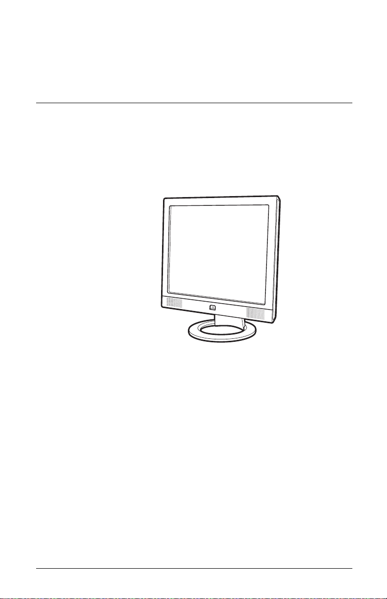
FP9419 LCD Monitor
Page 2

Page 3

The information in this document is subject to change without notice.
Hewlett-Packard
®
Company makes no warranty of any kind with
regard to this material, including, but not limited to, the implied
warranties of merchantability and fitness for a particular purpose.
HP shall not be liable for errors contained herein or for incidental or
consequential damages in connection with the furnishing,
performance, or use of this material.
THE WARRANTY TERMS CONTAINED IN THIS STATEMENT, EXCEPT
TO THE EXTENT LAWFULLY PERMITTED, DO NOT EXCLUDE,
RESTRICT OR MODIFY AND ARE IN ADDITION TO ANY
MANDATORY STATUTORY RIGHTS APPLICABLE TO THE SALE OF
THIS PRODUCT OR SERVICE TO YOU.
HP assumes no responsibility for the use or reliability of its software
on equipment that is not furnished by HP.
This document contains proprietary information that is protected by
copyright. All rights are reserved. No part of this document may be
photocopied, reproduced, or translated to another language without
the prior written consent of HP.
Hewlett-Packard Company
P.O. Box 4010
Cupertino, CA 95015-4010
USA
© 2004 Hewlett-Packard Development Company, L.P.
All rights reserved.
Hewlett-Packard is a registered trademark of Hewlett-Packard
Company in the United States of America and other
countries/regions.
User’s Guide iii
Page 4

This product incorporates copyright protection technology that is
protected by method claims of certain U.S. patents and other
intellectual property rights owned by Macrovision Corporation and
other rights owners. Use of this copyright protection technology must
be authorized by Macrovision Corporation, and is intended for home
and other limited viewing uses only unless otherwise authorized by
Macrovision Corporation. Reverse engineering or disassembly is
prohibited. Apparatus Claims of U.S. Patent Nos. 4,631,603,
4,577,216, 4,819,098, and 4,907,093 licensed for limited viewing
uses only.
Other brand or product names are trademarks of their respective
holders.
HP supports lawful use of technology and does not endorse or
encourage the use of our products for purposes other than those
permitted by copyright law.
WARNING: Text set off in this manner indicates that failure to
Å
follow directions could result in bodily harm or loss of life.
CAUTION: Text set off in this manner indicates that failure to follow
Ä
directions could result in damage to equipment or loss of
information.
Text set off in this manner indicates additional information.
✎
iv User’s Guide
Page 5

Contents
1Product Features
2 Safety and Maintenance Guidelines
Important Safety Information . . . . . . . . . . . . . . . . 2–1
Maintenance Guidelines . . . . . . . . . . . . . . . . . . . 2–2
Cleaning the Monitor . . . . . . . . . . . . . . . . . . . . . 2–3
Shipping the Monitor . . . . . . . . . . . . . . . . . . . . . 2–4
Removing the Monitor Base . . . . . . . . . . . . . . 2–4
3 Setting Up the Monitor
Before You Begin . . . . . . . . . . . . . . . . . . . . . . . . 3–1
Installing the Monitor . . . . . . . . . . . . . . . . . . . . . 3–2
Placing the Monitor on a Desktop . . . . . . . . . . 3–2
Mounting the Monitor . . . . . . . . . . . . . . . . . . 3–4
Connecting the Monitor. . . . . . . . . . . . . . . . . . . . 3–7
Contents
4 Operating the Monitor
CD Software and Utilities . . . . . . . . . . . . . . . . . . 4–1
The Information File . . . . . . . . . . . . . . . . . . . . 4–1
The Image Color Matching File . . . . . . . . . . . . 4–2
Installing .INF and .ICM Files . . . . . . . . . . . . . 4–2
Using the Auto-Adjustment Function . . . . . . . . . 4–3
Front Panel Components . . . . . . . . . . . . . . . . . . . 4–5
Using the On-Screen Display . . . . . . . . . . . . . . . . 4–7
Adjusting Monitor Settings . . . . . . . . . . . . . . . 4–8
Selecting the Video Input Connectors . . . . . . . . . 4–11
Identifying Monitor Conditions . . . . . . . . . . . . . . 4–12
User’s Guide v
Page 6

Adjusting Screen Quality. . . . . . . . . . . . . . . . . . 4–13
Optimizing Analog Video . . . . . . . . . . . . . . 4–13
Entering User Modes . . . . . . . . . . . . . . . . . . 4–14
Power Saver Feature. . . . . . . . . . . . . . . . . . . . . 4–15
A Troubleshooting
Solving Common Problems . . . . . . . . . . . . . . . . . A–1
Using the World Wide Web . . . . . . . . . . . . . . . . A–3
Preparing to Call Technical Support . . . . . . . . . . . A–4
Locating the Rating Label . . . . . . . . . . . . . . . . A–4
B Technical Specifications
FP9419 LCD Monitor . . . . . . . . . . . . . . . . . . . . . B–1
Preset Video Modes . . . . . . . . . . . . . . . . . . . . . . B–3
LCD Monitor Quality and Pixel Policy . . . . . . . . . . B–4
Power Cord Set Requirements . . . . . . . . . . . . . . . B–5
C Agency Regulatory Notices
Contents
Federal Communications Commission Notice. . . . . C–1
Modifications . . . . . . . . . . . . . . . . . . . . . . . . C–2
Cables. . . . . . . . . . . . . . . . . . . . . . . . . . . . . C–2
Declaration of Conformity
for Products Marked with FCC Logo,
United States Only . . . . . . . . . . . . . . . . . . . . . . . C–3
Canadian Notice . . . . . . . . . . . . . . . . . . . . . . . . C–4
Avis Canadien . . . . . . . . . . . . . . . . . . . . . . . . . . C–4
European Notice . . . . . . . . . . . . . . . . . . . . . . . . C–4
Japanese Notice . . . . . . . . . . . . . . . . . . . . . . . . C–4
Korean Notice . . . . . . . . . . . . . . . . . . . . . . . . . . C–5
EPA Energy Star Compliance . . . . . . . . . . . . . . . . C–5
HP Recycling Program. . . . . . . . . . . . . . . . . . . . . C–5
TCO ‘99 Requirements . . . . . . . . . . . . . . . . . . . . C–6
Environmental Requirements . . . . . . . . . . . . . . C–8
User’s Guide vi
Page 7
1
Product Features
The FP9419 LCD Monitor (Liquid Crystal Display) has an active
matrix, Thin-Film Transistor (TFT) screen.
The flat panel monitor features include:
■ Large 19-inch (48.3 cm) diagonal viewable area display.
■ 1280 × 1024 factory-set resolution, plus full-screen support for
lower resolutions.
■ Dual video inputs supported:
❏ VGA Analog
❏ DVI-D supports Digital signal input
■ VGA analog and DVI-D digital signal cables included.
■ Fast response time of 16ms provides better experience for
gaming and graphics.
User’s Guide 1–1
Page 8

Product Features
■ Easy to view from a sitting or standing position, or while
moving from one side of the monitor to the other.
■ Tilt adjustment capabilities.
■ Removable pedestal and VESA 100mm mounting holes for
flexible mounting solutions including wall mounting.
■ Security lock slot.
■ Plug and Play capability, if supported by your system.
■ On-Screen Display (OSD) adjustments for ease of setup and
screen optimization. Choose English, French, German, Italian,
Spanish, or Dutch.
■ Integrated stereo speakers.
■ Audio support connections include a PC line-in connector, and
a headphone jack connector.
■ Integrated power supply.
■ Energy Saver feature reduces power consumption.
■ Complies with the following regulated specifications:
❏ EPA ENERGY STAR
❏ European Union CE Directives
❏ Swedish MPR II 1990
❏ TCO ‘99 Environmental Requirements
■ This CD includes:
❏ An Information file (INF)
❏ Image Color Matching file (ICM)
❏ Auto-adjustment pattern software
❏ This User’s Guide
1–2 User’s Guide
Page 9

Safety and Maintenance
Guidelines
Important Safety Information
A power cord is included with your monitor. If another cord is
used, use only a power source and connection appropriate for this
monitor. For information on the correct power cord set to use with
your monitor, see “Power Cord Set Requirements” in Appendix B.
WARNING: To reduce the risk of electric shock or damage to your
Å
equipment, do not disable the power cord grounding feature. The
grounding plug is an important safety feature. Connect the
equipment to a grounded (earthed) power outlet.
WARNING: For your safety, be sure that the grounded power outlet
Å
you plug the power cord into is easily accessible to the operator and
located as close to the equipment as possible. To disconnect power
from the equipment, unplug the power cord from the power outlet by
grasping the plug firmly. Never pull on the cord.
2
CAUTION: To protect your monitor, as well as your computer,
Ä
connect all power cords for your computer and its peripheral devices
(such as a monitor, printer, scanner) to a surge protection device
such as a power strip with surge protection or Uninterruptible Power
Supply (UPS).
Not all power strips provide surge protection; the power strips must
be specifically labeled as having this ability. Use a power strip
whose manufacturer offers a Damage Replacement Policy so you
can replace your equipment if surge protection fails.
User’s Guide 2–1
Page 10

Safety and Maintenance Guidelines
Maintenance Guidelines
To enhance the performance and extend the life of your monitor:
■ Do not open your monitor cabinet or attempt to service this
product yourself. If your monitor is not operating properly or
has been dropped or damaged, contact your HP authorized
dealer, reseller, or service provider.
■ Adjust only those controls that are described in the operating
instructions.
■ Use only a power source and connection appropriate for this
monitor, as indicated on the label/back plate of the monitor.
■ Be sure the total ampere rating of the products connected to
the outlet does not exceed the current rating of the electrical
outlet, and the total ampere rating of the products connected
to the cord does not exceed the rating of the cord. Look on the
power label to determine the ampere rating (AMPS or A) for
each device.
■ Install your monitor near an outlet that you can easily reach.
Disconnect the monitor by grasping the plug firmly and pulling
it from the outlet. Never disconnect the monitor by pulling
the cord.
■ Do not allow anything to rest on the power cord. Do not walk
on the cord.
■ Turn your monitor off when not in use. You can substantially
increase the life expectancy of your monitor by using a screen
saver program and turning off the monitor when not in use.
■ Unplug your monitor from the wall outlet before cleaning. Do
not use liquid cleaners or aerosol cleaners. Use a damp cloth
for cleaning. If the screen requires additional cleaning, use an
antistatic screen cleaner.
CAUTION: Do not use benzene, thinner, ammonia, or any other
Ä
volatile substances to clean your monitor or the screen. These
chemicals may damage the cabinet finish as well as the screen.
2–2 User’s Guide
Page 11

■ Keep your monitor in a well-ventilated area, away from
excessive light, heat or moisture.
■ Slots and openings in the cabinet are provided for ventilation.
These openings must not be blocked or covered. Never push
objects of any kind into cabinet slots or other openings.
■ Do not drop your monitor or place it on an unstable surface.
■ When removing the monitor base, you must lay the monitor
face down on a soft area to prevent it from getting scratched,
defaced, or broken.
Cleaning the Monitor
The monitor is a high-quality optical device that requires special
care when cleaning. To clean the monitor, follow these steps:
1. Turn off the monitor and the computer.
2. Unplug your monitor from the wall outlet before cleaning.
3. Wipe the screen with a soft, clean cloth.
Safety and Maintenance Guidelines
❏ If the screen requires additional cleaning, use an antistatic
screen cleaner.
4. Dust the monitor housing. Use a damp cloth to clean the
cabinet.
❏ If the cabinet requires additional cleaning, use a clean
cloth dampened with isopropyl alcohol.
CAUTION: Do not use benzene, thinner, ammonia, or any volatile
Ä
substance to clean the monitor screen or cabinet. These chemicals
may damage the monitor. Do not use liquid cleaners or aerosol
cleaners. Never use water to clean an LCD screen.
5. Plug in the monitor.
6. Turn on the computer and monitor.
User’s Guide 2–3
Page 12

Safety and Maintenance Guidelines
Shipping the Monitor
Keep the original packing box in a storage area. You may need it
later if you move or ship your monitor. When you ship the monitor,
you should remove the base from the pedestal.
Removing the Monitor Base
Read the following warning and caution statements before
beginning the procedure.
WARNING: Do not remove the base from the pedestal while
Å
the monitor is standing in the upright position. Attempting to remove
the base from the pedestal while the monitor is upright may injure
the user.
WARNING: Before disassembling the monitor, turn off the monitor
Å
power, and disconnect all power, video, and audio cables.
To disconnect power from the equipment, unplug the power cord
from the power outlet by grasping the plug firmly. Never pull on
the cord.
CAUTION: The screen is fragile. Placing the monitor screen down
Ä
on a flat, soft area prevents scratches, defacing, or breakage.
To remove the base from the pedestal:
1. Disconnect the power, video, and audio cables from the
monitor.
2. Lay the monitor face down on a flat, soft protected surface.
Turn the pedestal upright.
2–4 User’s Guide
Page 13
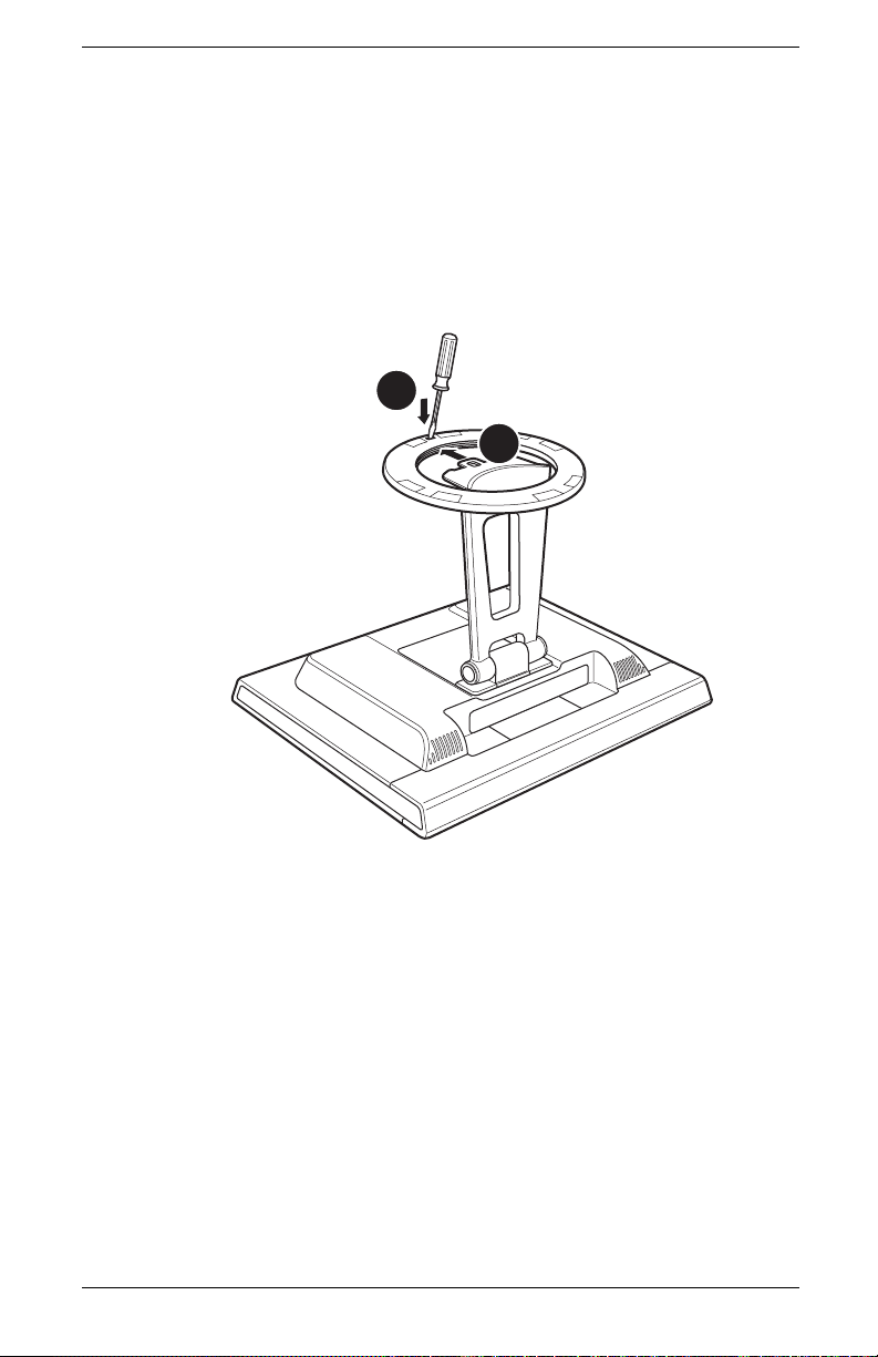
Safety and Maintenance Guidelines
3. On the bottom side of the base, carefully slide a slotted
screwdriver into the opening 1, as shown in the following
illustration. Push the screwdriver towards the top of the
monitor, slide the base 2 slightly back, towards the bottom
of the monitor, to unlock it. Pull the base completely away from
the pedestal with a firm grip.
1
2
Removing the Base from the Monitor Pedestal
4. Fold the pedestal hinge in the shipping position to the back of
the monitor. Remove only the base, not the hinge, when
shipping.
User’s Guide 2–5
Page 14

Safety and Maintenance Guidelines
2–6 User’s Guide
Page 15

Setting Up the Monitor
Before You Begin
1. Unpack the monitor. Make sure all contents are included. Store
the boxes.
2. Ensure that the power is turned off to the monitor, computer
system, and other attached devices (monitor ships in off
position).
3. Determine the video cable or cables that you will connect from
the computer video card outputs to the VGA and DVI inputs on
the monitor. You can connect one or both cables.
❏ VGA cable:
Standard VGA 15-pin cable.
❏ DVI-D cable:
For digital operation, use the DVI-D to DVI-D video cable
provided. The DVI-D cable supplied with this monitor is
for digital-to-digital connection only. Your computer must
have a DVI-compatible graphics card installed for use with
this cable.
3
4. Determine if the monitor will be desktop mounted or wall
mounted.
❏ See “Installing the Monitor”.
User’s Guide 3–1
Page 16

Setting Up the Monitor
Installing the Monitor
You can install the monitor on a desktop or wall mount. Place
the monitor in a convenient, well-ventilated location near your
computer.
If the monitor will be installed on a:
■ Desktop or table, see the “Placing the Monitor on a Desktop”
section.
■ Wall, swing arm, or other mounting fixture, see the “Mounting
the Monitor” section.
Connect the monitor after you have installed it. See “Connecting
the Monitor”.
Placing the Monitor on a Desktop
Before you place the monitor on a desktop or table, you must
attach the monitor base.
To place the monitor on a desktop or table:
1. Lay the monitor face down on a flat, soft, protected surface.
CAUTION: The screen is fragile. Placing the monitor screen down
Ä
on a flat, soft area prevents scratches, defacing, or breakage.
3–2 User’s Guide
Page 17
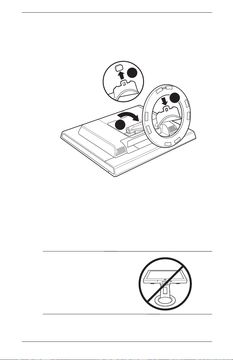
Setting Up the Monitor
2. Place the pedestal all the way towards the bottom of the
monitor as shown in the following illustration 1.
2
3
1
Inserting the Base onto the Monitor Pedestal
3. Remove the plastic cap on the pedestal end 2.
4. Using both hands, firmly push the circular base into the bottom
of the pedestal to lock the pedestal base in place 3. When the
base locks, it will make a clicking sound. Make sure the base
is securely locked onto the pedestal before continuing with the
setup.
5. Stand the monitor in the upright position.
WARNING: Tilt the monitor
Å
carefully. If you tilt the monitor back
more than 30 degrees, beyond its
easily adjustable position, it could
fall over. Position the monitor so
that it cannot fall off the table if
bumped.
User’s Guide 3–3
Page 18

Setting Up the Monitor
Mounting the Monitor
Before you mount the monitor on a wall, a swing arm or other
mounting fixture, you must remove the monitor pedestal and back
mounting cover. You will need a Phillips head screwdriver. Read
the following warning and caution statements before beginning the
procedure.
WARNING: Ensure that the monitor is lying flat, screen down.
Å
Attempting to remove the pedestal and base from the monitor while it
is upright may result in injury to the user.
CAUTION: Before disassembling the monitor, turn off the monitor
Ä
power, and disconnect all power, video, and audio cables.
If you are changing from a desktop installation to a wall mount,
✎
you must first remove the monitor base. See “Removing the Monitor
Base” in the previous chapter.
3–4 User’s Guide
Page 19
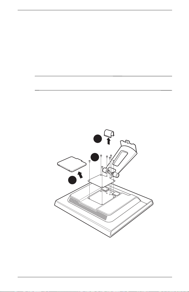
Setting Up the Monitor
To install the monitor on a wall, a swing arm or other mounting
fixture:
1. Pinch and remove the hinge cover and set it aside 1. Three
screws and the hinges are exposed.
2. Lay the monitor down on a flat, soft, protected surface. Turn
the pedestal upright.
CAUTION: The screen is fragile. Placing the monitor screen down
Ä
on a flat, soft area prevents scratches, defacing, or breakage.
3. Remove the rectangular back cover 2 as shown in the
following illustration. Four screws are exposed.
4. Turn the pedestal towards the bottom of the monitor.
5. Remove all seven screws 3. Use a Phillips head screwdriver.
1
3
2
Wall Mounting the Monitor
User’s Guide 3–5
Page 20

Setting Up the Monitor
6. Remove the pedestal.
7. Replace the hinge cover on the pedestal.
8. Save the screws, back cover, pedestal, and base for
future use.
9. Mount the monitor to a swing arm or other mounting fixture.
When the back cover has been removed, four threaded
mounting holes are exposed on the monitor panel. These
mounting holes are spaced 100 mm apart and are compliant
with the Video Electronics Standards Association (VESA)
standard for mounting flat panel monitors.
Use the four holes to attach a swing arm or other mounting
fixture. Follow the instructions included with the mounting
fixture, to insure that the monitor is safely attached.
3–6 User’s Guide
Page 21

Connecting the Monitor
To connect the monitor video input to the computer:
1. Place the monitor upright as shown in the following illustration.
2. Connect the video cable from the monitor to the video
connector on the rear panel of the computer.
You can connect the VGA cable, the DVI-D cable, or both. Only
✎
one cable is connected for typical installations.
❏ Connect one end of the 15-pin VGA cable to the VGA
input connector on the monitor. Then connect the other
end to the VGA output connector on the computer.
VGA
Setting Up the Monitor
TV-OUT
LCD
Connecting the VGA Cable
User’s Guide 3–7
Page 22

Setting Up the Monitor
❏ Connect one end of the DVI-D cable to the DVI input
connector on the monitor. Then connect the other end to
the DVI connector on the computer.
DVI
TV-OUT
LCD
Connecting the DVI-D Cable
3–8 User’s Guide
Page 23

Setting Up the Monitor
3. Connect the PC audio line-out connector from the computer to
your monitor to enable the monitor speakers. Connect the
headphone jack connector (as needed).
TV-OUT
LCD
Connecting the Audio Cable
User’s Guide 3–9
Page 24

Setting Up the Monitor
4. Read the warning below. Then connect one end of the
power cable to the monitor, and the other end to an electrical
wall outlet.
Connecting the Power Cable
2
1
WARNING: To reduce the risk of electric shock or damage to your
Å
equipment:
Do not disable the power cord grounding plug. The grounding plug
is an important safety feature. Plug the power cord into a grounded
(earthed) electrical outlet.
Be sure that the grounded power outlet you plug the power cord into
is easily accessible to the operator and located as close to the
equipment as possible. A power cord should be routed so that it is
not likely to be walked on or pinched by items placed upon it or
against it.
Do not place anything on power cords or cables. Arrange them so
that no one may accidentally step on or trip over them. Do not pull
on a cord or cable.
See “Power Cord Set Requirements” for additional information.
3–10 User’s Guide
Page 25

Setting Up the Monitor
5. Apply power to the computer and monitor, and other attached
devices.
6. The Monitor Status displays:
❏ VGA Input: Active or No Input Signal
❏ DVI Input: Active or No Input Signal
❏ Mode: Settings
7. Adjust the monitor as needed for your comfort using the
monitor’s tilt adjustment capability.
Adjusting the Tilt
WARNING: Tilt the monitor
Å
carefully. If you tilt the monitor back
more than 30 degrees, beyond its
easily adjustable position, it could
fall over. Position the monitor so
that it cannot fall off the table if
bumped.
8. Test the monitor function. If it does not function correctly,
configure the monitor as described in the next chapter,
“Operating the Monitor”.
User’s Guide 3–11
Page 26

Setting Up the Monitor
3–12 User’s Guide
Page 27

Operating the Monitor
CD Software and Utilities
The CD included with this monitor contains two files you can install
on your computer:
■ An .INF (Information) file
■ An .ICM (Image Color Matching) file
This CD also contains the Auto-Adjustment utility. This single pattern
program helps improve the picture quality of your VGA input flat
panel monitor. See “Using the Auto-Adjustment Function.”
Adobe Acrobat Reader
installed from the menu.
The Information File
This monitor is Windows Plug and Play compatible and the
monitor will work correctly without installing the .INF file. The .INF
file (Information file) enables the computer to communicate with the
monitor and use all the monitor features. The .INF file defines
monitor resources used by Microsoft Windows
to ensure monitor compatibility with your computer’s graphics
adapter.
Monitor Plug and Play compatibility requires that the computer’s
graphics card is VESA DDC2 compliant and that the monitor
connects directly to the graphics card. Plug and Play does not
work through separate BNC type connectors or through
distribution buffers/boxes. You may have to install the .INF file
from the CD if these conditions are not met.
®
is supplied on this CD and can be
4
®
operating systems
User’s Guide 4–1
Page 28

Operating the Monitor
The Image Color Matching File
The .ICM files provide more accurate color representation by
supplying data to graphics programs to provide consistent color
matching from monitor screen to printer, or from scanner to the
monitor screen. The .ICM files contain a monitor color system
profile. These files are activated from within graphics programs
that support this feature.
The ICM color profile is written in accordance with the
✎
International Color Consortium (ICC) Profile Format Specification.
Installing .INF and .ICM Files
If you determine that you need to update these files, you can install
.INF and .ICM files from the CD, or download them from the
Internet.
Installing from the CD
To install .INF and .ICM files on your computer from the CD:
1. Insert the CD in your computer’s CD-ROM drive. The CD
menu displays.
2. View the “INF and ICM Readme” file.
3. Select Install INF and ICM Files.
4. Follow the on-screen instructions.
5. After the files have been installed, restart Windows.
6. Ensure that the proper resolutions and refresh rates appear in
the Windows Display control panel. Refer to your Operating
System documentation for more information.
You may need to install the digitally signed monitor INF or ICM
✎
files manually from the CD, in the event of an installation error.
Refer to the INF and ICM Readme file on the CD.
4–2 User’s Guide
Page 29

Operating the Monitor
Downloading from the World Wide Web
To download the latest version of .INF and .ICM files from the
HP Monitors Support Web site:
1. Refer to: http://www.hp.com/support
Select your country/region.
2. Follow the links for your monitor to the support page and
download page.
3. Ensure your system meets the requirements.
4. Download the software by following the instructions.
Using the Auto-Adjustment Function
You can easily optimize the screen performance for the VGA input
by using the Select/Auto button and the auto-adjustment pattern
software on the CD provided.
Do not use this procedure if your monitor is using a DVI input. If
your monitor is using an analog (VGA) input, this procedure can
correct the following image quality conditions:
■ Fuzzy or unclear focus
■ Ghosting, streaking or shadowing effects
■ Faint vertical bars
■ Thin horizontal scrolling lines
■ Picture off-center
To use the Adjustment pattern with your flat panel monitor:
1. Press the Select/Auto button under the monitor’s front panel.
❏ You can also press the Menu button, then select Auto
Adjustment from the OSD Main Menu. See the
“Adjusting Monitor Settings” section.
❏ If the result is not satisfactory, continue with the procedure.
User’s Guide 4–3
Page 30

Operating the Monitor
2. Insert the CD in your computer’s CD-ROM drive. The CD menu
launches.
3. Select Open Auto-Adjustment Software.
4. The setup test pattern displays.
5. Press the Select/Auto button on the monitor front panel to
produce a stable, centered image.
4–4 User’s Guide
Page 31

Front Panel Components
The monitor buttons are located under the front panel.
BC D EF G
A
Operating the Monitor
User’s Guide 4–5
Page 32

Operating the Monitor
‘
No. Control Function
A
(Headphone jack)
B
(On/Off)
Cmenu
(On-Screen
Display)
–/1
D
(Minus)
+/2
E
(Plus)
F Select
−Auto OSD Menu Active
Connects a headphone set to the monitor.
When the headphone jack is connected, the monitor
speakers are muted.
Power Switch
Turns monitor on and off.
OSD Menu Active
Button closes OSD.
(Also closes setting screens
on OSD menu.)
OSD Menu Active
Button navigates down or
left browse, and adjusts
settings down.
OSD Menu Active
Button navigates up or
right browse, and adjusts
settings.
Button acts as an Enter
(Select) key to select
setting screen options.
Power LED
Fully powered: Green
Sleep mode: Amber
OSD Inactive
Button opens OSD
(activates).
OSD Inactive
Button selects the VGA
video input.
OSD Inactive
Button selects the DVI-D
video input.
OSD Inactive
Auto-adjustment.
Button automatically
adjusts the display to the
ideal setting.
G
(Volume control)
Speakers Audio feature for music, alarms, and other sounds.
4–6 User’s Guide
Controls the volume level of the monitor speakers. Turn
counter-clockwise to increase volume. Turn clockwise
to decrease volume.
Page 33

Using the On-Screen Display
Press the menu button under the front panel of your monitor to view
the On-Screen Display (OSD) Menu. The Main Menu window
displays on top of the contents of the screen. You can use the +
and – keys to control the monitor’s features.
1. If the monitor is not already on, press the Power switch to turn
on the monitor.
2. To access the OSD Menu, press the menu button under the
monitor’s front panel. The OSD Main Menu displays.
Main Menu
Brightness
Contrast
Auto Adjustment
Advanced Menu
Exit
Operating the Monitor
3. To access the Advanced OSD Menu, press the menu button
again. The OSD Advanced Menu displays. See the next
section for more information.
4. To navigate through the Main or Advanced OSD Menu, press
the + (Plus) button on the monitor’s front panel to scroll up, or
the – (Minus) button to scroll in reverse.
❏ The menu will move to the top if you scroll down at the
bottom of the selections. The menu will move to the bottom
if you scroll up at the top of the selections.
5. To select an item from the OSD Menu, use the + or – buttons to
scroll to and highlight your selection, then press the Select
button to select that function.
6. To adjust the scale of a selected item, press the + or – buttons.
User’s Guide 4–7
Page 34

Operating the Monitor
7. Select Save and Return.
❏ If you don’t want to save the setting, select Cancel from
the Advanced Menu or Exit from the Main Menu.
8. Press the menu button to exit the OSD.
If the buttons remain untouched for 30 seconds (factory default)
✎
while displaying a menu, new adjustments will be discarded,
except for brightness and contrast. Any changed settings will revert
to previous settings and the menu will close.
Adjusting Monitor Settings
The screen adjustments are set in the On-Screen Display (OSD)
menus. Two OSD menus are available:
■ Main
■ Advanced
Main Menu OSD
To access the Main Menu OSD, press the menu button under the
monitor’s front panel. The Main Menu Level 1 displays.
The following table describes Main Menu selections and levels:
Main Menu
Menu Level 1 Menu Level 2
Brightness Adjustment Scale
Contrast Adjustment Scale
Auto Adjustment (Analog only)
Advanced Menu
Exit
4–8 User’s Guide
Page 35

Operating the Monitor
Advanced Menu OSD
To access the Advanced Menu OSD, press the menu button again
(twice), or select Advanced Menu from the Main Menu. The
Advanced Menu level 1 displays.
After selecting the Advanced Menu from the Main Menu, the
✎
Advanced Menu remains the default OSD on subsequent
power-ups of the monitor until the Main Menu is selected or
Factory Reset is applied.
The Advanced Menu OSD has up to three levels and can be
viewed in one of six available languages. The following table
describes Advanced Menu selections, levels and factory presets:
Advanced Menu OSD
Level 1 Level 2 Level 3
Brightness Adjustment Scale 90
Contrast Adjustment Scale 80
Image Control
(Analog only)
Color 9300 K
Language Deutsch
Auto Adjustment “Adjusting”
Message
Horizontal Position Adjustment Scale
Vertical Position Adjustment Scale
Clock Adjustment Scale
Clock Phase Adjustment Scale
Cancel
Save and Return
6500 K 6500 K
Custom Color Custom Color
Adjustment
Cancel
Save and Return
English English
Español
Factory Preset
User’s Guide 4–9
Page 36

Operating the Monitor
Advanced Menu OSD (Continued)
Level 1 Level 2 Level 3
Français
Italiano
Nederlands
Cancel
Save and Return
Management Power Saver On/Off Selection On
Power On Recall On/Off Selection On
Mode Display On/Off Selection Off
Serial Number (Display Serial
Number)
Basic Menu Main (Basic)
Cancel
Save and Return
OSD Control Horizontal Position Adjustment Scale 50
Vertical Position Adjustment Scale 50
OSD Timeout Adjustment Scale 30 Seconds
OSD Transparency Adjustment Scale
Save and Return
Cancel
Video Input
Controls
Factory Reset Yes
Exit
Input Selection Analog (D-SUB)
Digital (DVI)
Auto Detect
Cancel
No
Factory Preset
4–10 User’s Guide
Page 37

Operating the Monitor
Selecting the Video Input Connectors
The two input connectors are:
1. VGA connector (analog)
2. DVI-D connector (digital)
The monitor will automatically determine which inputs have valid
video signals and display the image. The inputs can be manually
selected through the On-Screen Display (OSD) feature, or on the
front of the monitor by pressing the -/1 button for VGA input or
the +/2 button for DVI input.
The monitor displays the following conditions:
VGA Input Status DVI-D Input Status Monitor Displays:
Active Video Active Video Default Mode per OSD
Active Video Inactive Video Analog Video
Active Video No Connect Analog Video
Inactive Video Active Video Digital Video
No Connect Active Video Digital Video
Inactive Video Inactive Video Sleep Mode
Inactive Video No Connect Sleep Mode
No Connect Inactive Video Sleep Mode
No Connect No Connect “Check Video Cable”
message
CAUTION: Burn-in image damage may occur on monitors that
Ä
display the same static image on screen for a prolonged period of
time. To avoid burn-in image damage on your monitor screen, you
should always activate a screen saver application or turn off the
monitor when it is not in use for a prolonged period of time.
User’s Guide 4–11
Page 38

Operating the Monitor
Identifying Monitor Conditions
Special messages will display on the monitor screen for the
following monitor conditions:
■ Input Signal Out of Range
SET MONITOR TO:
1280 x 1024 @ 60 Hz
Moves around screen — Indicates the monitor does not
support the video input signal because the resolution and/or
refresh rate are set higher than the monitor supports.
Set the resolution and refresh rate for 1280 x 1024 at 60 Hz.
Restart your computer for the new settings to take effect.
■ Going to Sleep — Indicates the screen display is entering a
sleep mode. The speakers are turned off in sleep mode.
■ Check Video Cable — Indicates the video cable is not
properly connected to the computer or monitor.
■ OSD Lock —The OSD can be enabled or disabled by
pressing and holding the menu button on the front panel for
10 seconds. If the OSD is locked, the warning message
“OSD Lock” displays for ten seconds.
❏ If the OSD is locked, press and hold the menu button for
10 seconds to unlock the OSD.
❏ If the OSD is unlocked, press and hold the menu button
for 10 seconds to lock the OSD.
■ No Signal Input — Indicates the monitor is not receiving a
video signal from the computer or either of the two monitor
video input connectors. Check to see if the computer or input
signal source is off or in the power saving mode.
■ Multiple Inputs are active — Use the OSD to select
the desired video input — Indicates the monitor has more
than one video input.
■ Auto Adjustment is in Progress — Indicates the Auto
Adjustment function is active. See “Adjusting Screen Quality”.
4–12 User’s Guide
Page 39

Adjusting Screen Quality
The Auto-adjustment feature automatically fine-tunes the image
quality for display size, position, clock, and phase each time a
new video mode is displayed. For more precise adjustments, run
the Auto-Adjust software on the CD. See “Using the
Auto-Adjustment Function”.
If additional image quality improvement is desired, use the Clock
and Phase controls of the monitor to fine-tune the image. See
“Optimizing Analog Video”.
Optimizing Analog Video
This monitor contains advanced circuitry that allows the flat panel
screen to function as a standard analog monitor. Two controls in
the Advanced Menu OSD (On-Screen Display) can be adjusted to
improve analog image performance:
■ Clock — Increase or decrease the value to minimize any
vertical bars or stripes visible on the screen background.
Operating the Monitor
■ Clock Phase — Increase or decrease the value to minimize
video distortion or video jitter.
Use these controls only when the auto-adjust function does not
provide a satisfactory monitor image in analog mode.
To obtain the best results:
1. Allow the monitor to warm up for 20 minutes before adjusting.
2. Display the adjustment pattern application provided on
the CD.
3. Access the Advanced Menu OSD; select Image Control.
4. Set the main Clock correctly first, since the Clock Phase
settings depend on the main Clock setting.
❏ When adjusting the Clock and Clock Phase values, if the
monitor images become distorted, continue adjusting the
values until the distortion disappears.
To restore the factory settings, access the Advanced Menu OSD,
select Factory Reset, and select Yes .
User’s Guide 4–13
Page 40

Operating the Monitor
Entering User Modes
The video controller signal may occasionally require a custom user
mode if you are not using a standard graphics adapter or preset
mode. In this condition, you may need to create a user mode. You
can use the OSD (On-Screen Display) to:
■ Create a user-defined mode with custom monitor screen
parameters.
■ Readjust the parameters of any user mode.
■ Save them in memory. The monitor automatically stores the
new setting, then recognizes the new mode just as it does a
preset mode.
Ten user modes can be entered and stored, in addition to the 15
factory preset modes (see the table “Factory Preset Video Input
Modes” in Appendix B).
4–14 User’s Guide
Page 41

Power Saver Feature
When the monitor is in normal operating mode, the Power light is
green and the monitor uses less than 50 watts of power.
The monitor also supports a power saver mode that is controlled
by the PC. When the monitor is in the reduced power state, the
monitor screen is blank, the backlight is off, the speakers are off,
and the Power light is amber. The monitor will use less than 2 watts
of power. The energy saving reduced power state will activate if
the monitor does not detect either the horizontal sync signal
and/or the vertical sync signal. The OSD Power Saver feature
must be activated on your PC for this feature to work.
A brief warm-up period occurs before the monitor returns to normal
operating mode.
Refer to your computer manual for instructions on setting energy
saver features (sometimes called power management features).
The above energy saver feature works only when the monitor is
✎
connected to computers that have energy saver features.
Operating the Monitor
User’s Guide 4–15
Page 42

Operating the Monitor
4–16 User’s Guide
Page 43

Troubleshooting
Solving Common Problems
The following table lists possible problems, the possible cause of
each problem, and the recommended solutions.
Problem Possible Cause Solution
A
Screen is blank. Power cord is
disconnected.
Power switch is
turned off.
Video cable is
improperly connected.
Screen blanking utility is
active.
Image appears
blurred, indistinct, or
too dark.
Brightness and contrast
are too low.
Connect the power cord.
Turn on the power.
Connect the video cable
properly. See Chapter 3,
“Setting Up the Monitor,”
for more information.
Press any key on the
keyboard or move the
mouse to turn off the screen
blanking utility.
Press the Auto button on the
front panel. If this does not
correct the image, press the
Menu button to open the
Basic OSD Menu, and
adjust the brightness and
contrast scales as needed.
User’s Guide A–1
Page 44

Troubleshooting
Problem Possible Cause Solution
Image is not
centered.
“No Connection,
Check Signal Cable”
is displayed on
screen.
“Out of Range. Set
Monitor to 1280 x
1024 @ 60Hz” is
displayed on screen.
Position may need
adjustment.
Monitor video cable is
disconnected.
Video resolution and/or
refresh rate are set
higher than what your
monitor supports.
Press the Menu button to
access the OSD Menu.
Select Image Control/
Horizontal Position or
Vertic a l Position to adjust
the horizontal or vertical
position of the image.
Connect the 15-pin monitor
video cable to the VGA
connector on the computer,
or connect the DVI-D signal
cable to the DVI connector
on the computer. Be sure
that the computer power is
off while connecting the
video cable.
Restart your computer and
enter Safe Mode. Change
your settings to a supported
setting (see the table in
“Preset Video Modes” in
Appendix B). Restart your
computer so that the new
settings take effect.
A–2 User’s Guide
Page 45

Using the World Wide Web
Before contacting customer service, refer to the HP Support Web
site at: http://www.hp.com/support
Select your country/region, and then follow the links to the support
page for your monitor.
Troubleshooting
User’s Guide A–3
Page 46

Troubleshooting
Preparing to Call Technical Support
If you cannot solve a problem using the troubleshooting tips in this
section, you may need to call technical support. Have the
following available when you call:
■ The monitor
■ Monitor model number (located on label in back of monitor)
■ Monitor serial number (located on label in back of monitor)
■ Purchase date on invoice
■ Conditions under which the problem occurred
■ Error messages received
■ Hardware configuration
■ Name and version of the hardware and software you
are using
Locating the Rating Label
The rating label on the monitor provides the spare part number,
product number, and serial number. You may need these numbers
when contacting HP about your monitor model.
Locate the FP9419 monitor rating label on the rear cover between
the connectors and buttons.
A–4 User’s Guide
Page 47

Technical Specifications
FP9419 LCD Monitor
FP9419 LCD Monitor
B
Display
Type
Viewable Image Size 19.0-inch diagonal 48.3 cm
Tilt –5 to 30
Face Treatment Anti-glare polarizer with hard coating
Maximum Weight 15.4 lbs. (unpacked) 7 kg (unpacked)
Dimensions (including Base)
Height
Width
Depth
Maximum Graphics Resolution 1280 x 1024 (75 Hz) analog and digital modes
Text Mode 720 x 400
Dot Pitch 0.294 x 0.294 mm
Horizontal Frequency
(analog mode)
Vertical Refresh Rate
(analog mode)
19.0 inches
TFT LCD Active Matrix
o
17.7 inches
16.8 inches
9.1 inches
30 to 83 kHz
56 to 76 Hz
48.3 cm
449.9 mm
426.7 mm
230 mm
User’s Guide B–1
Page 48

Technical Specifications
FP9419 LCD Monitor (Continued)
Environmental Requirements
Tempe ra tur e:
Operating Temperature
Non-operating Temperature
41 to 95
–4 to 140
Relative Humidity 20 to 80%
Power Source 100–240V , 50/60 Hz
Power Consumption <50 watts typical
Sleep Power Consumption <2 watts typical
Input Terminals 1 VGA 15-pin D-type
connector
2 DVI-D connector
All performance specifications are provided by the component
manufacturers. Performance specifications represent the highest
specification of all HP’s component manufacturers’ typical level
specifications for performance and actual performance may vary either
higher or lower.
o
F
o
F
o
5 to 35
–20 to 60
C
o
C
Analog cable included
DVI-D cable included
B–2 User’s Guide
Page 49

Technical Specifications
Preset Video Modes
This monitor automatically recognizes fifteen preset video input
modes that will appear properly sized and centered on the screen.
The following modes are assigned at the factory and are the most
commonly used display resolutions.
Factory Preset Video Input Modes
Preset Pixel Format Horz Freq (kHz) Vert Freq (Hz)
1 640 x 480 31.5 60.0
2 640 x 480 37.9 72.0
3 640 x 480 37.5 75.0
4 720 x 400 31.5 70.0
5 800 x 600 37.9 60.0
6 800 x 600 48.1 72.0
7 800 x 600 46.9 75.0
8 832 x 624 49.7 75.0
9 1024 x 768 48.4 60.0
10 1024 x 768 60.0 75.0
11 1152 x 870 68.7 75.0
12 1152 x 900 71.8 76.5
13 1280 x 960 60.0 60.0
14 1280 x 1024 63.9 60.0
15 1280 x 1024 80.0 75.0
User’s Guide B–3
Page 50

Technical Specifications
LCD Monitor Quality and Pixel Policy
The FP9419 LCD Monitor uses high-precision technology,
manufactured according to high standards, to guarantee
trouble-free performance. Nevertheless, the display may have
cosmetic imperfections that appear as small bright or dark spots.
This is common to all LCD displays used in products supplied by all
vendors and is not specific to the FP9419 LCD Monitor. These
imperfections are caused by one or more defective pixels or
sub-pixels.
■ A pixel consists of one red, one green, and one blue sub-pixel.
■ A defective whole pixel is always turned on (a bright spot on a
dark background), or it is always off (a dark spot on a bright
background). The first is the more visible of the two.
■ A defective sub-pixel (dot defect) is less visible than a defective
whole pixel and is small and only visible on a specific
background.
The FP9419 LCD Monitor has:
■ Less than 5 total dot defects
■ 0 defective full pixels
■ 3 defective bright sub-pixels (maximum)
■ 5 defective dark sub-pixels (maximum)
■ No more than two adjacent (less than 2.5 mm edge-to-edge)
and defective pixels
■ No more than two pairs of two adjacent defective pixels
To locate defective pixels, the monitor should be viewed under
normal operating conditions and in normal operating mode at
a supported resolution and refresh rate, from a distance of
approximately 50 cm (16 in.).
We expect that, over time, the industry will continue to improve its
ability to produce displays with fewer cosmetic imperfections and
we will adjust guidelines as improvements are made.
B–4 User’s Guide
Page 51

Technical Specifications
Power Cord Set Requirements
The monitor power supply is provided with Automatic Line
Switching (ALS). This feature allows the monitor to operate on input
voltages between 100–120V or 200–240V .
The power cord set (flexible cord or wall plug) received with the
monitor meets the requirements for use in the country where you
purchased the equipment.
If you need to obtain a power cord for a different country, you
should purchase a power cord that is approved for use in that
country.
The power cord must be rated for the product and for the voltage
and current marked on the product’s electrical ratings label. The
voltage and current rating of the cord should be greater than the
voltage and current rating marked on the product. In addition, the
cross-sectional area of the wire must be a minimum of 0.75 mm² or
18AWG, and the length of the cord must be between 6 feet
(1.8 m) and 12 feet (3.6 m). If you have questions about the type
of power cord to use, contact your HP authorized service provider.
A power cord should be routed so that it is not likely to be walked
on or pinched by items placed upon it or against it. Particular
attention should be paid to the plug, electrical outlet, and the point
where the cord exits from the product.
User’s Guide B–5
Page 52

Technical Specifications
B–6 User’s Guide
Page 53

Agency Regulatory Notices
Federal Communications Commission Notice
This equipment has been tested and found to comply with the limits
for a Class B digital device, pursuant to Part 15 of the FCC Rules.
These limits are designed to provide reasonable protection against
harmful interference in a residential installation. This equipment
generates, uses, and can radiate radio frequency energy and, if
not installed and used in accordance with the instructions, may
cause harmful interference to radio communications. However,
there is no guarantee that interference will not occur in a particular
installation. If this equipment does cause harmful interference to
radio or television reception, which can be determined by turning
the equipment off and on, the user is encouraged to try to correct
the interference by one or more of the following measures:
■ Reorient or relocate the receiving antenna.
C
■ Increase the separation between the equipment and the
receiver.
■ Connect the equipment into an outlet on a circuit different from
that to which the receiver is connected.
■ Consult the dealer or an experienced radio or television
technician for help.
User’s Guide C–1
Page 54

Agency Regulatory Notices
Modifications
The FCC requires the user to be notified that any changes or
modifications made to this device that are not expressly approved
by Hewlett-Packard Company may void the user’s authority to
operate the equipment.
Cables
Connections to this device must be made with shielded cables with
metallic RFI/EMI connector hoods to maintain compliance with
FCC Rules and Regulations.
C–2 User’s Guide
Page 55

Agency Regulatory Notices
Declaration of Conformity for Products Marked with FCC Logo, United States Only
This device complies with Part 15 of the FCC Rules. Operation is
subject to the following two conditions: (1) this device may not
cause harmful interference, and (2) this device must accept any
interference received, including interference that may cause
undesired operation.
For questions regarding your product, contact:
Hewlett-Packard Company
P. O. Box 692000, Mail Stop 530113
Houston, Texas 77269-2000
Or, call
1-800-474-6836
For questions regarding this FCC declaration, contact:
Hewlett-Packard Company
P. O. Box 692000, Mail Stop 510101
Houston, Texas 77269-2000
Or, call
(281) 514-3333
To identify this product, refer to the part, series, or model number
found on the product.
User’s Guide C–3
Page 56

Agency Regulatory Notices
Canadian Notice
This Class B digital apparatus meets all requirements of the
Canadian Interference-Causing Equipment Regulations.
Avis Canadien
Cet appareil numérique de la classe B respecte toutes les
exigences du Règlement sur le matériel brouilleur du Canada.
European Notice
Products with the CE Marking comply with both the EMC Directive
(89/336/EEC) and the Low Voltage Directive (73/23/EEC)
issued by the Commission of the European Community.
Compliance with these directives implies conformity to the
following European Norms (in brackets are the equivalent
international standards):
■ EN55022 (CISPR 22) — Electromagnetic Interference
■ EN55024 (IEC61000-4-2,3,4,5,6,8,11) — Electromagnetic
Immunity
■ EN61000-3-2 (IEC61000-3-2) — Power Line Harmonics
■ EN61000-3-3 (IEC61000-3-3) — Power Line Flicker
■ EN60950 (IEC60950) — Product Safety
Japanese Notice
C–4 User’s Guide
Page 57

Agency Regulatory Notices
Korean Notice
EPA Energy Star Compliance
Monitors that are marked with the Energy Star® Logo meet the
requirements of the EPA Energy Star program. As an Energy Star
Partner, Hewlett-Packard Company has determined that this
product meets the Energy Star guidelines for energy efficiency.
Specific details on using the energy saving features can be found
in the energy saver or power management section of the computer
manual.
HP Recycling Program
HP offers product end-of-life return programs for HP and other
manufacturers’ hardware in several geographic areas.
The terms and availability of these programs vary by geography
because of differences in regulatory requirements and local
customer demand. For information on the HP recycling program,
refer to the HP Web site at:
http://www.hp.com/hpinfo/globalcitizenship/
environment/recycle/hardware.html
User’s Guide C–5
Page 58

Agency Regulatory Notices
TCO ‘99 Requirements
You have just purchased a TCO ‘99 approved and labeled
product! Your choice has provided you with a product developed
for professional use. Your purchase has also contributed to
reducing the burden on the environment and to the further
development of environmentally adapted electronics products.
Why do we have environmentally labeled computers?
In many countries/regions, environmental labeling has become an
established method for encouraging the adaptation of goods and
services to the environment. The main problem, as far as
computers and other electronics equipment are concerned, is that
environmentally harmful substances are used both in the products
and during their manufacture. Since it is not so far possible to
satisfactorily recycle the majority of electronics equipment, most of
these potentially damaging substances sooner or later enter nature.
There are also other characteristics of a computer, such as energy
consumption levels, that are important from the viewpoints of both
the work (internal) and natural (external) environments. Since all
methods of electricity generation have a negative effect on the
environment (for example, acidic and climate-influencing
emissions, radioactive waste), it is vital to save energy. Electronics
equipment in offices is often left running continuously and thereby
consumes a lot of energy.
C–6 User’s Guide
Page 59

Agency Regulatory Notices
What does the environmental labeling involve?
This product meets the requirements for the TCO ‘99 scheme which
provides for an international and environmental labeling of
personal computers. The labeling scheme was developed as a
joint effort by the TCO (The Swedish Confederation of Professional
Employees), Svenska Naturskyddsforeningen (The Swedish Society
for Nature Conservation), Statens Energimyndighet (The Swedish
National Energy Administration), and SEMKO AB.
The requirements cover a wide range of issues: environmental,
ergonomic, usability, reduction of electric and magnetic fields,
energy consumption, and electrical safety.
The environmental demands impose restrictions on the presence
and use of heavy metals, brominated and chlorinated flame
retardants, CFCs (freons) and chlorinated solvents, among other
things. The product must be prepared for recycling, and the
manufacturer is obliged to have an environmental policy which
must be adhered to in each country/region where the company
implements its operational policy.
The energy requirements include a demand that the computer
and/or monitor, after a certain period of inactivity, shall reduce
its power consumption to a lower level in one or more stages.
The length of time to reactivate the computer shall be reasonable
for the user.
Below, you will find a brief summary of the environmental
requirements met by this product. The complete environmental
criteria document may be ordered from:
TCO Development
SE-114 94 Stockholm, Sweden
Fax: +46 8 782 92 07
E-mail (Internet): development@tco.se
Current information regarding TCO ‘99 approved and labeled
products may also be obtained over the Internet, using the
address:
http://www.tco-info.com/
User’s Guide C–7
Page 60

Agency Regulatory Notices
Environmental Requirements
Flame retardants:
Flame retardants are present in printed circuit boards, cables,
wires, casings and housings. Their purpose is to prevent, or at
least to delay, the spread of fire. Up to 30% of the plastic in a
computer casing can consist of flame retardant substances. Most
flame retardants contain bromine or chloride, and those flame
retardants are chemically related to another group of
environmental toxins, PCBs. Both the flame retardants containing
bromine or chloride and the PCBs are suspected of giving rise to
severe health effects, including reproductive damage in fish-eating
birds and mammals, due to the bio-accumulative
Flame retardants have been found in human blood and
researchers fear that disturbances in fetus development may occur.
The relevant TCO ’99 demand requires that plastic components
weighing more than 25 grams must not contain flame retardants
with organically bound bromine or chlorine. Flame retardants are
allowed in the printed circuit boards since no substitutes are
available.
Cadmium:
Cadmium is present in rechargeable batteries and in the
colour-generating layers of certain computer displays. Cadmium
damages the nervous system and is toxic in high doses. The
relevant TCO ‘99 requirement states that batteries, the
color-generating layers of display screens and the electrical or
electronics components must not contain any cadmium.
1
1
processes.
1. Bio-accumulative is defined as substances which accumulate within living
organisms. Lead, Cadmium and Mercury are heavy metals which are
bio-accumulative.
C–8 User’s Guide
Page 61

Agency Regulatory Notices
Mercury:
1
Mercury is sometimes found in batteries, relays and switches. It
damages the nervous system and is toxic in high doses. The
relevant TCO ‘99 requirement states that batteries may not contain
any mercury. It also demands that mercury is not present in any of
the electrical or electronics components associated with the
labeled unit. There is however one exception. Mercury is, for the
time being, permitted in the back light system of flat panel monitors
as there today is no commercially available alternative. TCO aims
on removing this exception when a mercury-free alternative is
available.
CFCs (freons):
The relevant TCO ‘99 requirement states that neither CFCs nor
HCFCs may be used during the manufacture and assembly of the
product. CFCs (freons) are sometimes used for washing printed
circuit boards. CFCs break down ozone and thereby damage the
ozone layer in the stratosphere, causing increased reception on
earth of ultraviolet light with e.g. increased risks of skin cancer
(malignant melanoma) as a consequence.
1
Lead:
Lead can be found in picture tubes, display screens, solders and
capacitors. Lead damages the nervous system and in higher doses,
causes lead poisoning. The relevant TCO ‘99 requirement permits
the inclusion of lead since no replacement has yet been
developed.
1. Bio-accumulative is defined as substances which accumulate within living
organisms. Lead, Cadmium and Mercury are heavy metals which are
bio-accumulative.
User’s Guide C–9
Page 62

Agency Regulatory Notices
C–10 User’s Guide
 Loading...