

Page 1

HPE FlexFabric 12900E Switch Series
Layer 3—IP Routing Configuration Guide
P
Software
Document version: 6W101-20161201
art number: 5200-1237a
version: Release 2606 and later
Page 2

© Copyright 2016 Hewlett Packard Enterprise Development LP
The information contained herein is subject to change without notice. The only warranties for Hewlett Packard
Enterprise products and services are set forth in the express warranty statements accompanying such
products and services. Nothing herein should be construed as constituting an additional warranty. Hewlett
Packard Enterprise shall not be liable for technical or editorial errors or omissions contained herein.
Confidential computer software. Valid license from Hewlett Packard Enterprise required for possession, use, or
copying. Consistent with FAR 12.211 and 12.212, Commercial Computer Software, Computer Software
Documentation, and Technical Data for Commercial Items are licensed to the U.S. Government under vendor’s
standard commercial license.
Links to third-party websites take you outside the Hewlett Packard Enterprise website. Hewlett Packard
Enterprise has no control over and is not responsible for information outside the Hewlett Packard Enterprise
website.
Acknowledgments
Intel®, Itanium®, Pentium®, Intel Inside®, and the Intel Inside logo are trademarks of Intel Corporation in the
United States and other countries.
Microsoft® and Windows® are trademarks of the Microsoft group of companies.
Adobe® and Acrobat® are trademarks of Adobe Systems Incorporated.
Java and Oracle are registered trademarks of Oracle and/or its affiliates.
UNIX® is a registered trademark of The Open Group.
Page 3

Contents
Configuring basic IP routing ··········································································· 1
Routing table ······················································································································································ 1
Dynamic routing protocols·································································································································· 2
Route preference ··············································································································································· 2
Load sharing ······················································································································································ 3
Route backup ····················································································································································· 3
Route recursion ·················································································································································· 3
Route redistribution ············································································································································ 3
Extension attribute redistribution ························································································································ 3
Setting the maximum lifetime for routes and labels in the RIB··········································································· 4
Setting the maximum lifetime for routes in the FIB ···························································································· 4
Configuring RIB NSR ········································································································································· 5
Configuring IPv4 RIB NSR ························································································································· 5
Configuring IPv6 RIB NSR ························································································································· 5
Configuring inter-protocol FRR ·························································································································· 6
Configuring IPv4 RIB inter-protocol FRR ··································································································· 6
Configuring IPv6 RIB inter-protocol FRR ··································································································· 6
Enabling the IPv4 enhanced ECMP mode ········································································································· 7
Displaying and maintaining a routing table ········································································································ 7
Configuring static routing ··············································································· 9
Configuring a static route ··································································································································· 9
Configuring BFD for static routes ····················································································································· 10
Bidirectional control mode ························································································································ 10
Single-hop echo mode ····························································································································· 11
Configuring static route FRR ···························································································································· 12
Configuration guidelines ··························································································································· 12
Configuring static route FRR by specifying a backup next hop································································ 12
Configuring static route FRR to automatically select a backup next hop ················································· 13
Enabling BFD echo packet mode for static route FRR ············································································ 13
Displaying and maintaining static routes ·········································································································· 13
Static route configuration examples ················································································································· 14
Basic static route configuration example ·································································································· 14
BFD for static routes configuration example (direct next hop) ································································· 15
BFD for static routes configuration example (indirect next hop) ······························································ 18
Static route FRR configuration example ·································································································· 20
Configuring a default route ··········································································· 23
Configuring RIP ··························································································· 24
Overview ·························································································································································· 24
RIP route entries ······································································································································ 24
Routing loop prevention ··························································································································· 24
RIP operation ··········································································································································· 24
RIP versions ············································································································································· 25
Protocols and standards ·························································································································· 25
RIP configuration task list································································································································· 25
Configuring basic RIP ······································································································································ 26
Enabling RIP ············································································································································ 26
Controlling RIP reception and advertisement on interfaces ····································································· 27
Configuring a RIP version ························································································································ 27
Configuring RIP route control ··························································································································· 28
Configuring an additional routing metric ··································································································· 28
Configuring RIPv2 route summarization ·································································································· 29
Disabling host route reception ·················································································································· 30
Advertising a default route ······················································································································· 30
Configuring received/redistributed route filtering······················································································ 30
i
Page 4

Setting a preference for RIP ····················································································································· 31
Configuring RIP route redistribution ········································································································· 31
Tuning and optimizing RIP networks ··············································································································· 32
Configuration prerequisites ······················································································································ 32
Setting RIP timers ···································································································································· 32
Enabling split horizon and poison reverse ······························································································· 33
Setting the maximum number of RIP ECMP routes ················································································· 33
Enabling zero field check on incoming RIPv1 messages ········································································· 34
Enabling source IP address check on incoming RIP updates·································································· 34
Configuring RIPv2 message authentication ····························································································· 34
Setting the RIP triggered update interval ································································································· 35
Specifying a RIP neighbor ························································································································ 35
Configuring RIP network management ···································································································· 36
Configuring the RIP packet sending rate ································································································· 36
Setting the maximum length of RIP packets ···························································································· 37
Setting the DSCP value for outgoing RIP packets ··················································································· 37
Configuring RIP GR ········································································································································· 37
Enabling RIP NSR············································································································································ 38
Configuring BFD for RIP ·································································································································· 38
Configuring single-hop echo detection (for a directly connected RIP neighbor) ······································ 39
Configuring single-hop echo detection (for a specific destination) ··························································· 39
Configuring bidirectional control detection ······························································································· 40
Configuring RIP FRR ······································································································································· 40
Configuration restrictions and guidelines ································································································· 40
Configuration prerequisites ······················································································································ 41
Configuring RIP FRR ······························································································································· 41
Enabling BFD for RIP FRR ······················································································································ 41
Displaying and maintaining RIP ······················································································································· 41
RIP configuration examples ····························································································································· 42
Configuring basic RIP ······························································································································ 42
Configuring RIP route redistribution ········································································································· 45
Configuring an additional metric for a RIP interface················································································· 47
Configuring RIP to advertise a summary route ························································································ 48
Configuring RIP GR ································································································································· 51
Configuring RIP NSR ······························································································································· 52
Configuring BFD for RIP (single-hop echo detection for a directly connected neighbor) ························· 53
Configuring BFD for RIP (single hop echo detection for a specific destination) ······································· 56
Configuring BFD for RIP (bidirectional detection in BFD control packet mode) ······································· 58
Configuring RIP FRR ······························································································································· 61
Configuring OSPF························································································ 64
Overview ·························································································································································· 64
OSPF packets ·········································································································································· 64
LSA types ················································································································································· 64
OSPF areas ············································································································································· 65
Router types ············································································································································· 67
Route types ·············································································································································· 68
Route calculation ······································································································································ 68
OSPF network types ································································································································ 69
DR and BDR ············································································································································ 69
Protocols and standards ·························································································································· 70
OSPF configuration task list ····························································································································· 70
Enabling OSPF ················································································································································ 72
Configuration prerequisites ······················································································································ 72
Configuration guidelines ··························································································································· 73
Enabling OSPF on a network ··················································································································· 73
Enabling OSPF on an interface················································································································ 74
Configuring OSPF areas ·································································································································· 74
Configuring a stub area ···························································································································· 74
Configuring an NSSA area ······················································································································· 75
Configuring a virtual link ··························································································································· 75
Configuring OSPF network types ····················································································································· 76
ii
Page 5

Configuration prerequisites ······················································································································ 76
Configuring the broadcast network type for an interface·········································································· 76
Configuring the NBMA network type for an interface ··············································································· 76
Configuring the P2MP network type for an interface················································································ 77
Configuring the P2P network type for an interface··················································································· 78
Configuring OSPF route control ······················································································································· 78
Configuration prerequisites ······················································································································ 78
Configuring OSPF route summarization ·································································································· 78
Configuring received OSPF route filtering ································································································ 79
Configuring Type-3 LSA filtering ·············································································································· 80
Setting an OSPF cost for an interface······································································································ 80
Setting the maximum number of ECMP routes ························································································ 81
Setting OSPF preference ························································································································· 81
Configuring discard routes for summary networks ··················································································· 81
Configuring OSPF route redistribution ····································································································· 82
Advertising a host route ··························································································································· 83
Excluding interfaces in an OSPF area from the base topology································································ 83
Tuning and optimizing OSPF networks ············································································································ 84
Configuration prerequisites ······················································································································ 84
Setting OSPF timers ································································································································ 84
Setting LSA transmission delay ··············································································································· 85
Setting SPF calculation interval ··············································································································· 85
Setting the LSA arrival interval ················································································································· 86
Setting the LSA generation interval·········································································································· 86
Disabling interfaces from receiving and sending OSPF packets ····························································· 87
Configuring stub routers ··························································································································· 87
Configuring OSPF authentication············································································································· 88
Adding the interface MTU into DD packets ······························································································ 89
Setting the DSCP value for outgoing OSPF packets ··············································································· 89
Setting the maximum number of external LSAs in LSDB········································································· 89
Setting OSPF exit overflow interval·········································································································· 89
Enabling compatibility with RFC 1583······································································································ 90
Logging neighbor state changes ·············································································································· 90
Configuring OSPF network management ································································································ 91
Setting the LSU transmit rate ··················································································································· 91
Setting the maximum length of OSPF packets that can be sent by an interface ····································· 92
Enabling OSPF ISPF ······························································································································· 92
Configuring prefix suppression ················································································································· 92
Configuring prefix prioritization ················································································································· 93
Configuring OSPF PIC ····························································································································· 94
Setting the number of OSPF logs ············································································································ 95
Filtering outbound LSAs on an interface ·································································································· 95
Filtering LSAs for the specified neighbor ································································································· 95
Configuring GTSM for OSPF ··················································································································· 96
Configuring OSPF GR······································································································································ 97
Configuring OSPF GR restarter ··············································································································· 97
Configuring OSPF GR helper ··················································································································· 98
Triggering OSPF GR ································································································································ 98
Configuring OSPF NSR ··································································································································· 99
Configuring BFD for OSPF······························································································································· 99
Configuring bidirectional control detection ······························································································· 99
Configuring single-hop echo detection ··································································································· 100
Configuring OSPF FRR·································································································································· 100
Configuration prerequisites ···················································································································· 100
Configuration guidelines ························································································································· 101
Configuration procedure ························································································································· 101
Advertising OSPF link state information to BGP ···························································································· 102
Displaying and maintaining OSPF ················································································································· 102
OSPF configuration examples ······················································································································· 104
Basic OSPF configuration example ······································································································· 104
OSPF route redistribution configuration example ·················································································· 106
OSPF route summarization configuration example ················································································ 108
iii
Page 6

OSPF stub area configuration example ································································································· 111
OSPF NSSA area configuration example ······························································································ 113
OSPF DR election configuration example ······························································································ 115
OSPF virtual link configuration example ································································································ 119
OSPF GR configuration example ··········································································································· 121
OSPF NSR configuration example········································································································· 124
BFD for OSPF configuration example ···································································································· 126
OSPF FRR configuration example ········································································································· 129
Troubleshooting OSPF configuration ············································································································· 131
No OSPF neighbor relationship established ·························································································· 131
Incorrect routing information ·················································································································· 132
Configuring IS-IS ······················································································· 133
Overview ························································································································································ 133
Terminology ··········································································································································· 133
IS-IS address format ······························································································································ 133
NET ························································································································································ 134
IS-IS area ··············································································································································· 135
IS-IS network types ································································································································ 136
IS-IS PDUs ············································································································································· 137
Protocols and standards ························································································································ 139
IS-IS configuration task list····························································································································· 139
Configuring basic IS-IS ·································································································································· 140
Configuration prerequisites ···················································································································· 140
Enabling IS-IS ········································································································································ 141
Setting the IS level and circuit level ······································································································· 141
Configuring P2P network type for an interface ······················································································· 141
Configuring IS-IS route control ······················································································································· 142
Configuration prerequisites ···················································································································· 142
Configuring IS-IS link cost ······················································································································ 142
Specifying a preference for IS-IS ··········································································································· 143
Configuring the maximum number of ECMP routes ··············································································· 144
Configuring IS-IS route summarization ·································································································· 144
Advertising a default route ····················································································································· 145
Configuring IS-IS route redistribution ····································································································· 145
Configuring IS-IS route filtering ·············································································································· 145
Configuring IS-IS route leaking ·············································································································· 146
Tuning and optimizing IS-IS networks ··········································································································· 147
Configuration prerequisites ···················································································································· 147
Specifying the interval for sending IS-IS hello packets ·········································································· 147
Specifying the IS-IS hello multiplier········································································································ 147
Specifying the interval for sending IS-IS CSNP packets ········································································ 148
Configuring a DIS priority for an interface ······························································································ 148
Disabling an interface from sending/receiving IS-IS packets ································································· 148
Enabling an interface to send small hello packets ················································································· 149
Configuring LSP parameters ·················································································································· 149
Controlling SPF calculation interval ······································································································· 151
Configuring convergence priorities for specific routes ··········································································· 152
Setting the LSDB overload bit ················································································································ 152
Configuring the ATT bit ·························································································································· 153
Configuring the tag value for an interface ······························································································ 153
Configuring system ID to host name mappings ····················································································· 154
Enabling the logging of neighbor state changes ···················································································· 155
Enabling IS-IS ISPF ······························································································································· 155
Enabling prefix suppression ··················································································································· 155
Configuring IS-IS network management ································································································ 156
Configuring IS-IS PIC ····························································································································· 157
Enhancing IS-IS network security ·················································································································· 158
Configuration prerequisites ···················································································································· 158
Configuring neighbor relationship authentication ··················································································· 158
Configuring area authentication ············································································································· 158
Configuring routing domain authentication····························································································· 159
iv
Page 7

Configuring IS-IS GR ····································································································································· 159
Configuring IS-IS NSR ··································································································································· 160
Configuring BFD for IS-IS ······························································································································ 161
Configuring IS-IS FRR ··································································································································· 161
Configuration prerequisites ···················································································································· 162
Configuration guidelines ························································································································· 162
Configuration procedure ························································································································· 162
Displaying and maintaining IS-IS ··················································································································· 163
IS-IS configuration examples ························································································································· 165
Basic IS-IS configuration example ········································································································· 165
DIS election configuration example········································································································ 169
IS-IS route redistribution configuration example ···················································································· 173
IS-IS authentication configuration example···························································································· 177
IS-IS GR configuration example············································································································· 180
IS-IS NSR configuration example ·········································································································· 181
BFD for IS-IS configuration example ······································································································ 184
IS-IS FRR configuration example··········································································································· 187
Configuring BGP ························································································ 191
Overview ························································································································································ 191
BGP speaker and BGP peer ·················································································································· 191
BGP message types ······························································································································ 191
BGP path attributes ································································································································ 191
BGP route selection ······························································································································· 195
BGP route advertisement rules ·············································································································· 195
BGP load balancing ······························································································································· 196
Settlements for problems in large-scale BGP networks ········································································· 197
MP-BGP ················································································································································· 200
BGP multi-instance ································································································································ 201
BGP configuration views ························································································································ 201
Protocols and standards ························································································································ 203
BGP configuration task list ····························································································································· 203
Configuring basic BGP ··································································································································· 206
Enabling BGP ········································································································································· 206
Configuring a BGP peer ························································································································· 207
Configuring dynamic BGP peers ············································································································ 209
Configuring a BGP peer group ··············································································································· 211
Specifying the source address of TCP connections ··············································································· 220
Generating BGP routes ·································································································································· 221
Injecting a local network ························································································································· 221
Redistributing IGP routes ······················································································································· 223
Controlling route distribution and reception ··································································································· 224
Configuring BGP route summarization ··································································································· 224
Advertising optimal routes in the IP routing table ··················································································· 227
Advertising a default route to a peer or peer group················································································ 228
Limiting routes received from a peer or peer group ··············································································· 230
Configuring BGP route filtering policies ································································································· 231
Configuring BGP route update delay ····································································································· 237
Configuring BGP route dampening ········································································································ 238
Controlling BGP path selection ······················································································································ 239
Setting a preferred value for routes received ························································································· 239
Configuring preferences for BGP routes ································································································ 241
Configuring the default local preference ································································································ 242
Configuring the MED attribute ················································································································ 244
Configuring the NEXT_HOP attribute ···································································································· 248
Configuring the AS_PATH attribute ······································································································· 250
Ignoring IGP metrics during optimal route selection ·············································································· 255
Configuring the SoO attribute ················································································································· 256
Tuning and optimizing BGP networks ············································································································ 258
Configuring the keepalive interval and hold time ··················································································· 258
Configuring the interval for sending updates for the same route ··························································· 259
Enabling BGP to establish an EBGP session over multiple hops ·························································· 260
v
Page 8

Enabling immediate re-establishment of direct EBGP connections upon link failure ····························· 261
Enabling 4-byte AS number suppression ······························································································· 262
Enabling MD5 authentication for BGP peers ························································································· 263
Enabling keychain authentication for BGP peers ··················································································· 264
Configuring BGP load balancing ············································································································ 265
Disabling BGP to establish a session to a peer or peer group ······························································· 266
Configuring GTSM for BGP ···················································································································· 267
Configuring BGP soft-reset ···················································································································· 268
Protecting an EBGP peer when memory usage reaches level 2 threshold ··········································· 274
Configuring an update delay for local MPLS labels ··············································································· 275
Flushing the suboptimal BGP route to the RIB ······················································································ 276
Setting a DSCP value for outgoing BGP packets ·················································································· 276
Enabling per-prefix label allocation ········································································································ 277
Disabling optimal route selection for labeled routes without tunnel information ····································· 277
Configuring a large-scale BGP network ········································································································· 278
Configuring BGP community ·················································································································· 278
Configuring BGP route reflection ··········································································································· 280
Configuring a BGP confederation ·········································································································· 282
Configuring BGP GR ······································································································································ 283
Configuring BGP NSR···································································································································· 284
Enabling SNMP notifications for BGP ············································································································ 285
Enabling logging for session state changes ··································································································· 285
Enabling logging for BGP route flapping ········································································································ 286
Configuring BFD for BGP ······························································································································· 288
Configuring BGP FRR ···································································································································· 289
Configuring 6PE ············································································································································· 292
Configuring basic 6PE ···························································································································· 292
Configuring optional 6PE capabilities····································································································· 293
Configuring BGP LS ······································································································································· 295
Configuring basic BGP LS ····················································································································· 295
Configuring BGP LS route reflection ······································································································ 295
Specifying an AS number and a router ID for BGP LS messages ························································· 296
Displaying and maintaining BGP···················································································································· 296
Displaying BGP ······································································································································ 296
Resetting BGP sessions ························································································································ 299
Clearing BGP information ······················································································································ 299
IPv4 BGP configuration examples ················································································································· 300
Basic BGP configuration example·········································································································· 300
BGP and IGP route redistribution configuration example ······································································ 304
BGP route summarization configuration example ·················································································· 307
BGP load balancing configuration example ··························································································· 310
BGP community configuration example ································································································· 313
BGP route reflector configuration example ···························································································· 316
BGP confederation configuration example····························································································· 318
BGP path selection configuration example ···························································································· 322
BGP GR configuration example ············································································································· 325
BFD for BGP configuration example ······································································································ 326
BGP FRR configuration example ··········································································································· 330
Multicast BGP configuration example ···································································································· 334
Dynamic BGP peer configuration example ···························································································· 337
BGP LS configuration example ·············································································································· 339
IPv6 BGP configuration examples ················································································································· 341
IPv6 BGP basic configuration example ·································································································· 341
IPv6 BGP route reflector configuration example ···················································································· 344
6PE configuration example ···················································································································· 347
BFD for IPv6 BGP configuration example ······························································································ 350
IPv6 BGP FRR configuration example ··································································································· 353
Troubleshooting BGP ····································································································································· 357
Symptom ················································································································································ 357
Analysis ·················································································································································· 357
Solution ·················································································································································· 357
vi
Page 9

Configuring PBR ························································································ 358
Overview ························································································································································ 358
Policy ······················································································································································ 358
PBR and Track ······································································································································· 359
PBR configuration task list ····························································································································· 359
Configuring a policy········································································································································ 360
Creating a node ······································································································································ 360
Setting match criteria for a node ············································································································ 360
Configuring actions for a node ··············································································································· 361
Specifying a policy for PBR ···························································································································· 361
Specifying a policy for local PBR ··········································································································· 361
Specifying a policy for interface PBR ····································································································· 362
Specifying a policy for outbound PBR on a VXLAN tunnel interface ····················································· 362
Displaying and maintaining PBR ···················································································································· 363
PBR configuration examples ·························································································································· 363
Packet type-based local PBR configuration example ············································································ 363
Packet type-based interface PBR configuration example ······································································ 365
Configuring IPv6 static routing ··································································· 367
Configuring an IPv6 static route ····················································································································· 367
Configuring BFD for IPv6 static routes ··········································································································· 367
Bidirectional control mode ······················································································································ 368
Single-hop echo mode ··························································································································· 368
Displaying and maintaining IPv6 static routes································································································ 369
IPv6 static routing configuration examples ···································································································· 369
Basic IPv6 static route configuration example ······················································································· 369
BFD for IPv6 static routes configuration example (direct next hop) ······················································· 371
BFD for IPv6 static routes configuration example (indirect next hop) ···················································· 374
Configuring an IPv6 default route······························································· 377
Configuring RIPng ····················································································· 378
Overview ························································································································································ 378
RIPng route entries ································································································································ 378
RIPng packets ········································································································································ 378
Protocols and standards ························································································································ 379
RIPng configuration task list··························································································································· 379
Configuring basic RIPng ································································································································ 379
Configuring RIPng route control ····················································································································· 380
Configuring an additional routing metric ································································································· 380
Configuring RIPng route summarization ································································································ 380
Advertising a default route ····················································································································· 381
Configuring received/redistributed route filtering···················································································· 381
Setting a preference for RIPng ··············································································································· 381
Configuring RIPng route redistribution ··································································································· 382
Tuning and optimizing the RIPng network ····································································································· 382
Setting RIPng timers ······························································································································ 382
Configuring split horizon and poison reverse ························································································· 383
Configuring zero field check on RIPng packets ····················································································· 383
Setting the maximum number of ECMP routes ······················································································ 384
Configuring the RIPng packet sending rate ··························································································· 384
Setting the interval for sending triggered updates ·················································································· 385
Configuring RIPng GR ··································································································································· 385
Configuring RIPng NSR ································································································································· 386
Configuring RIPng FRR ································································································································· 386
Configuration restrictions and guidelines ······························································································· 387
Configuration prerequisites ···················································································································· 387
Configuring RIPng FRR ························································································································· 387
Enabling BFD for RIPng FRR ················································································································ 387
Displaying and maintaining RIPng ················································································································· 388
RIPng configuration examples ······················································································································· 388
vii
Page 10

Basic RIPng configuration example ······································································································· 388
RIPng route redistribution configuration example ·················································································· 391
RIPng GR configuration example··········································································································· 393
RIPng NSR configuration example ········································································································ 394
Configuring RIPng FRR ························································································································· 396
Configuring OSPFv3 ·················································································· 399
Overview ························································································································································ 399
OSPFv3 packets ···································································································································· 399
OSPFv3 LSA types ································································································································ 399
Protocols and standards ························································································································ 400
OSPFv3 configuration task list ······················································································································· 400
Enabling OSPFv3··········································································································································· 401
Configuring OSPFv3 area parameters ··········································································································· 402
Configuration prerequisites ···················································································································· 402
Configuring a stub area ·························································································································· 402
Configuring an NSSA area ····················································································································· 402
Configuring an OSPFv3 virtual link ········································································································ 403
Configuring OSPFv3 network types ··············································································································· 403
Configuration prerequisites ···················································································································· 404
Configuring the OSPFv3 network type for an interface ·········································································· 404
Configuring an NBMA or P2MP neighbor ······························································································ 404
Configuring OSPFv3 route control ················································································································· 405
Configuration prerequisites ···················································································································· 405
Configuring OSPFv3 route summarization ····························································································· 405
Configuring OSPFv3 received route filtering ·························································································· 406
Configuring Inter-Area-Prefix LSA filtering ····························································································· 406
Setting an OSPFv3 cost for an interface ································································································ 406
Setting the maximum number of OSPFv3 ECMP routes ······································································· 407
Setting a preference for OSPFv3 ··········································································································· 407
Configuring OSPFv3 route redistribution ······························································································· 408
Tuning and optimizing OSPFv3 networks ······································································································ 409
Configuration prerequisites ···················································································································· 409
Setting OSPFv3 timers ··························································································································· 409
Setting LSA transmission delay ············································································································· 410
Setting SPF calculation interval ············································································································· 410
Setting the LSA generation interval········································································································ 410
Setting a DR priority for an interface ······································································································ 411
Ignoring MTU check for DD packets ······································································································ 411
Disabling interfaces from receiving and sending OSPFv3 packets ························································ 411
Enabling logging for neighbor state changes ························································································· 412
Configuring OSPFv3 network management··························································································· 412
Setting the LSU transmit rate ················································································································· 413
Configuring stub routers ························································································································· 413
Configuring prefix suppression ··············································································································· 414
Setting the maximum number of OSPFv3 logs ······················································································ 415
Configuring OSPFv3 authentication ······································································································· 415
Configuring OSPFv3 GR ································································································································ 416
Configuring GR restarter ························································································································ 416
Configuring GR helper ··························································································································· 417
Triggering OSPFv3 GR ·························································································································· 417
Configuring OSPFv3 NSR······························································································································ 417
Configuring BFD for OSPFv3 ························································································································· 418
Configuring OSPFv3 FRR ······························································································································ 418
Configuration prerequisites ···················································································································· 419
Configuration guidelines ························································································································· 419
Configuration procedure ························································································································· 419
Displaying and maintaining OSPFv3·············································································································· 421
OSPFv3 configuration examples···················································································································· 422
OSPFv3 stub area configuration example ····························································································· 422
OSPFv3 NSSA area configuration example ·························································································· 426
OSPFv3 DR election configuration example ·························································································· 428
viii
Page 11

OSPFv3 route redistribution configuration example··············································································· 431
OSPFv3 route summarization configuration example ············································································ 434
OSPFv3 GR configuration example ······································································································· 438
OSPFv3 NSR configuration example ····································································································· 439
BFD for OSPFv3 configuration example ································································································ 440
OSPFv3 FRR configuration example ····································································································· 443
Configuring IPv6 IS-IS ··············································································· 446
Overview ························································································································································ 446
Configuring basic IPv6 IS-IS ·························································································································· 446
Configuring IPv6 IS-IS route control ·············································································································· 447
Configuring IPv6 IS-IS link cost·············································································································· 448
Tuning and optimizing IPv6 IS-IS networks ··································································································· 449
Configuration prerequisites ···················································································································· 449
Assigning a convergence priority to IPv6 IS-IS routes ··········································································· 449
Setting the LSDB overload bit ················································································································ 450
Configuring a tag value on an interface ································································································· 450
Controlling SPF calculation interval ······································································································· 450
Enabling IPv6 IS-IS ISPF ······················································································································· 451
Enabling prefix suppression ··················································································································· 451
Configuring BFD for IPv6 IS-IS ······················································································································ 451
Configuring IPv6 IS-IS FRR ··························································································································· 452
Configuration prerequisites ···················································································································· 452
Configuration procedure ························································································································· 453
Enabling IPv6 IS-IS MTR ······························································································································· 454
Displaying and maintaining IPv6 IS-IS ··········································································································· 455
IPv6 IS-IS configuration examples ················································································································· 455
IPv6 IS-IS basic configuration example ································································································· 455
BFD for IPv6 IS-IS configuration example ····························································································· 460
IPv6 IS-IS FRR configuration example ·································································································· 462
Configuring IPv6 PBR ················································································ 466
Overview ························································································································································ 466
Policy ······················································································································································ 466
PBR and Track ······································································································································· 467
IPv6 PBR configuration task list ····················································································································· 467
Configuring an IPv6 policy ····························································································································· 467
Creating an IPv6 node ··························································································································· 467
Setting match criteria for an IPv6 node ·································································································· 468
Configuring actions for an IPv6 node ····································································································· 468
Configuring IPv6 PBR ···································································································································· 469
Configuring IPv6 local PBR ···················································································································· 469
Configuring IPv6 interface PBR ············································································································· 469
Displaying and maintaining IPv6 PBR············································································································ 470
IPv6 PBR configuration examples·················································································································· 470
Packet type-based IPv6 local PBR configuration example ···································································· 470
Packet type-based IPv6 interface PBR configuration example ······························································ 472
Configuring routing policies ········································································ 475
Overview ························································································································································ 475
Filters ····················································································································································· 475
Routing policy ········································································································································· 475
Configuring filters ··········································································································································· 476
Configuration prerequisites ···················································································································· 476
Configuring an IP prefix list ···················································································································· 476
Configuring an AS path list ····················································································································· 477
Configuring a community list ·················································································································· 477
Configuring an extended community list ································································································ 477
Configuring a routing policy···························································································································· 478
Configuration prerequisites ···················································································································· 478
Creating a routing policy ························································································································ 478
Configuring if-match clauses ·················································································································· 478
ix
Page 12

Configuring apply clauses ······················································································································ 480
Configuring the continue clause ············································································································· 481
Displaying and maintaining the routing policy ································································································ 482
Routing policy configuration examples ·········································································································· 482
Routing policy configuration example for IPv4 route redistribution ························································ 482
Routing policy configuration example for IPv6 route redistribution ························································ 485
Document conventions and icons ······························································ 488
Conventions ··················································································································································· 488
Network topology icons ·································································································································· 489
Support and other resources ····································································· 490
Accessing Hewlett Packard Enterprise Support····························································································· 490
Accessing updates ········································································································································· 490
Websites ················································································································································ 490
Customer self repair ······························································································································· 491
Remote support ······································································································································ 491
Documentation feedback ······················································································································· 491
Index ·········································································································· 492
x
Page 13

Configuring basic IP routing
Criterion
Categories
The destination is a netw ork. T he subnet mask i s les s than 32
Whether the
•
•
•
•
IP routing directs IP packet forwarding on routers based on a routing table. This chapter focuses on
unicast routing protoc ols. For more inf ormation about m ulticast routing protoco ls, see IP Multicast
Configuration Guide.
Routing table
A RIB contains the global routing information and related information, including route recursion, route
redistribution, and ro ute extension information. The r outer selects optimal routes f rom the routing
table and puts them into the FIB table. It uses the FIB table to forward packets. For more information
about the FIB table, see Layer 3—IP Services Configuration Guide.
Table 1 categorizes routes by different criteria.
Table 1 Route categories
• Network route—
Destination
bits.
• Host route—The destination is a host. The subnet mask is 32 bits.
destination is directly
connected
Origin
• Direct route—The destination is directly connected.
• Indirect route—The destination is indirectly connected.
• Direct route—A direct route is discovered by the data link protocol on an
interface, and is also called an interface route.
• Static route—A static route is manually configured by an administrator.
• Dynamic route—A dynamic route is dynamically discovered by a routing
protocol.
To view brief information about a routing table, use the display ip routing-table command.
<Sysname> display ip routing-table
Destinations : 9 Routes : 9
Destination/Mask Proto Pre Cost NextHop Interface
0.0.0.0/32 Direct 0 0 127.0.0.1 InLoop0
3.3.3.3/32 Direct 0 0 127.0.0.1 InLoop0
127.0.0.0/8 Direct 0 0 127.0.0.1 InLoop0
127.0.0.0/32 Direct 0 0 127.0.0.1 InLoop0
127.0.0.1/32 Direct 0 0 127.0.0.1 InLoop0
127.255.255.255/32 Direct 0 0 127.0.0.1 InLoop0
...
A route entry includes the following key items:
Destination—IP address of the destination host or network.
Mask—Mask length of the IP address.
Proto—Protocol that installed the route.
Pre—Preference of the route. Among routes to the same destination, the route with the highest
preference is optimal.
1
Page 14

•
•
•
Criterion
Categories
RIP and BGP. BGP is also
Route type
Preference
Cost—If multiple routes to a destination have the same preference, the one with the smallest
cost is the optimal route.
NextHop—Next hop.
Interface—Output interface.
Dynamic routing protocols
Static routes work well in small, stable networks. They are easy to configure and require fewer
system resources. However, in networks where topology changes occur frequently, a typical practice
is to configure a dynamic routing protocol. Compared with static routing, a dynamic routing protocol
is complicated to configure, requires more router resources, and consumes more network resources.
Dynamic routing protocols dynamically collect and report reachability information to adapt to
topology changes. They are suitable for large networks.
Dynamic routing protocols can be classified by different criteria, as shown in Table 2.
Table 2 Categories of dynamic routing protocols
Operation scope
Routing algorithm
Destination address
type
IP version
• IGPs—Work within an AS. Examples includ e RIP, OSPF, and IS-IS.
• EGPs—Work between ASs. The most popular EGP is BGP.
• Distance-vector protocols—Examples include
considered a path-vector protocol.
• Link-state protocols—Examples include OSPF and IS-IS.
• Unicast routing protocols—Examples include RIP, OSPF, BGP, and IS-IS.
• Multicast routing protocols—Examples include PIM-SM and PIM-DM.
• IPv4 routing protocols—Examples include RIP, OSPF, BGP, and IS-IS.
• IPv6 routing protocols—Examples include RIPng, OSPFv3, IPv6 BGP, and
IPv6 IS-IS.
An AS refers to a group of routers that use the sam e routing policy and work under the same
administration.
Route preference
Routing protocols, includ in g stat ic and direc t r out ing, eac h b y defau lt have a preference. If they find
multiple routes to the sam e dest ination, the router selec ts the r oute with the hig hest pref erence as
the optimal route.
The preference of a direct route is always 0 and cannot be changed. Y ou can configure a preference
for each static route and each dynamic routing protocol. The following table lists the route types and
default preferences. The smaller the value, the higher the preference.
Table 3 Route types and default route preferences
Direct route 0
Multicast static route 1
OSPF 10
IS-IS 15
Unicast static route 60
2
Page 15

Route type
Preference
RIP 100
OSPF ASE 150
OSPF NSSA 150
IBGP 255
EBGP 255
Unknown (route from an untrusted source) 256
Load sharing
A routing protocol might find multiple optimal equal-cost routes to the same destination. You can use
these routes to implement equal-cost multi-path (ECMP) load sharing.
Static routing, IPv6 static routing, RIP, RIPng, OSPF, OSPFv3, BGP, IP v6 B GP, IS-IS, and IPv6 IS-IS
support ECMP load sharing.
Route backup
Route backup can im prove network availability. Among m ultiple rout es to the s ame destin ation, the
route with the highest priority is the prim ary route and others are secondary routes.
The router forwards m atching p ackets through the prim ary route. W hen the primar y route fails, the
route with the highest preference among the secondary routes is selected to forward packets. When
the primary route recovers, the router uses it to forward packets.
Route recursion
To use a BGP, s tatic , or R I P route that has an ind irec tl y co nnec t ed nex t ho p, a r o uter must perform
route recursion to find the output interface to reach the next hop.
Link-state routing pro tocols, such as O SPF and IS-IS, do not need route rec ursion, because th ey
obtain directly connected next hops through route calculation.
The RIB records and sa ves route recursion informati on, including brief information abo ut related
routes, recursive paths, and recur sion dep th.
Route redistribution
Route redistribution enables routing protocols to learn routing information from each other. A
dynamic routing pr otocol can redistribute routes from other routing protocols, including direct and
static routing. For more inform ation, see the respective c hapters on those ro uting protocols in this
configuration guide.
The RIB records redistribution relationships of routing protocols.
Extension attribute redistribution
Extension attribute redistribution enables routi ng protocols to learn route extension attri butes from
each other, including BGP extended comm unity attributes , OSPF area IDs , route types, and rout er
IDs.
3
Page 16

The RIB records extended attributes of each routing protocol and redistribution relationships of
Step
Command
Remarks
rib
y default, no RIB IPv4
y default, the maximum
Step
Command
Remarks
y default, no RIB IPv6
y default, the maximum
Step
Command
Remarks
y default, no RIB IPv4
different routing protocol extended attributes.
Setting the maximum lifetime for routes and labels in the RIB
Perform this task to prevent rout es of a certain protocol from being aged out due to slo w protocol
convergence resulting from a large number of route entries or long GR period.
The configuration takes effect at the next protocol or RIB process switchover.
To set the maximum lifetime for routes and labels in the RIB (IPv4):
1. Enter system view.
2. Enter RIB view.
3. Create the RIB IPv4 address
family and enter its view.
4. Set the maximum lifetime for
IPv4 routes and labels in the
RIB.
To set the maximum route lifetime for routes and labels in the RIB (IPv6):
1. Enter system view.
2. Enter RIB view.
3. Create the RIB IPv6 address
family and enter its view.
4. Set the maximum lifetime for
IPv6 routes and labels in the
RIB.
system-view
address-family ipv4
protocol
instance-name ]
system-view
rib
address-family ipv6
protocol
instance-name ]
protocol [
lifetime
protocol [
lifetime
instance
seconds
instance
seconds
N/A
N/A
B
address family exists.
B
lifetime for routes and labels
in the RIB is 480 seconds.
N/A
N/A
B
address family exists.
B
lifetime for routes and labels
in the RIB is 480 seconds.
Setting the maximum lifetime for routes in the FIB
When GR or NSR is disabled, FIB entries m ust be ret ained for s ome tim e after a protoco l proces s
switchover or RIB proces s switcho ver. When GR or NSR is enab led, FIB entri es m ust be removed
immediately after a protocol or RIB pr oc ess switchover to avoi d routing issues. Pe rf orm this task to
meet such requirements.
To set the maximum lifetime for routes in the FIB (IPv4):
1. Enter system view.
2. Enter RIB view.
3. Create the RIB IPv4 address
family and enter its view.
system-view
rib
address-family ipv4
4
N/A
N/A
B
address family exists.
Page 17

Step
Command
Remarks
4. Set the maximum lifetime for
y default, the maximum
lifetime for routes in the FIB
Step
Command
Remarks
y default, no RIB IPv6
y default, the maximum
lifetime for routes in the FIB
IMPORTANT:
Use this feature with protocol GR or NSR to avoid route timeouts and traffic interruption.
Step
Command
Remarks
By default, no RIB IPv4
By default, RIB NSR is
Step
Command
Remarks
RIB IPv6
IPv4 routes in the FIB.
To set the maximum lifetime for routes in the FIB (IPv6):
fib lifetime
seconds
B
is 600 seconds.
1. Enter system view.
2. Enter RIB view.
3. Create the RIB IPv6 address
family and enter its view.
4. Set the maximum lifetime for
IPv6 routes in the FIB.
system-view
rib
address-family ipv6
fib lifetime
Configuring RIB NSR
When an active/standby switchover occurs, nonstop routing (NSR) backs up routing information
from the active process to the standby process to a void routing flapping and ensure forwarding
continuity.
RIB NSR provides faster route convergence than protocol NSR during an active/standby switchover.
Configuring IP v4 RIB NSR
seconds
N/A
N/A
B
address family exists.
B
is 600 seconds.
1. Enter system view.
2. Enter RIB view.
3. Create the RIB IPv4 address
family and enter its view.
4. Enable IPv4 RIB NSR.
system-view
rib
address-family ipv4
non-stop-routing
Configuring IP v6 RIB NSR
1. Enter system view.
2. Enter RIB view.
3. Create the RIB IPv6 address
family and enter its view.
system-view
rib
address-family ipv6
5
N/A
N/A
address family exists.
disabled.
N/A
N/A
By default, no
address family exists.
Page 18

Step
Command
Remarks
4. Enable IPv6 RIB NSR.
By default, RIB NSR is
CAUTION:
This feature
faulty route, which might cause loops.
Step
Command
Remarks
By default, no RIB IPv4
Enable IPv4 RIB
protocol FRR
is enabled for the public
Step
Command
Remarks
By default, no RIB IPv6
Enable IPv6 RIB
protocol FRR
is enabled for the public
non-stop-routing
Configuring inter-protocol FRR
disabled.
uses the next hop of a route from a different protocol as the backup next hop for the
Inter-protocol fast reroute (FRR) enables fast rerouting between routes of different protocols. A
backup next hop is automatically selected to reduce the service interruption time caused by
unreachable next hops. W hen the next hop of the prim ary link fails, the traffic is redirected to the
backup next hop.
Among the routes to the same destination in the RIB, a router adds the route with the highest
preference to the FIB tab le. For example, if a static route and an O SPF route in the RI B have the
same destination, the router adds the OSPF ro ute to the FIB ta ble by default. The next hop of the
static route is selected as the backup next hop for the OSPF route. When the next hop of the OSPF
route is unreachable, the backup next hop is used.
Configuring IP v4 RIB inter-protoc ol FRR
1. Enter system view.
2. Enter RIB view.
3. Create the RIB IPv4 address
family and enter its view.
system-view
rib
address-family ipv4
N/A
N/A
address family exists.
4.
inter-protocol FRR.
inter-protocol fast-reroute
vpn-instance
[
vpn-instance-name ]
Configuring IP v6 RIB inter-protoc ol FRR
1. Enter system view.
2. Enter RIB view.
3. Create the RIB IPv6 address
family and enter its view.
4.
inter-protocol FRR.
system-view
rib
address-family ipv6
inter-protocol fast-reroute
vpn-instance
[
vpn-instance-name ]
By default, inter-protocol
FRR is disabled.
If you do not specify a VPN
instance, inter-
network.
N/A
N/A
address family exists.
By default, inter-protocol
FRR is disabled.
If you do not specify a VPN
instance, internetwork.
6
Page 19

Step
Command
Remarks
Enable the IPv4 enhanced
By default, the IPv4
enhanced ECMP mode is
Task
Command
information about routes
Display information about routes
routing table
Display next hop information in the
Enabling the IPv4 enhanced ECMP mode
When one or multiple ECMP routes fail, the default ECMP mode enables the device to reallocate all
traffic to the remaining routes.
The IPv4 enhanced ECMP mode enables the device to reallocate only the traffic of the failed routes
to the remaining routes, which ensures forwarding continuity.
This configuration takes effect at reboot. Make sure the reboot does not impact your network.
To enable the IPv4 enhanced ECMP mode:
1. Enter system view.
2.
ECMP mode.
system-view
ecmp mode enhanced
N/A
disabled.
Displaying and maintaining a routing table
Execute display commands in any view and reset commands in user view.
Display the IPv4 ECMP mode.
Display routing table information.
Display information about routes
permitted by an IPv4 basic ACL.
Display information about routes to a
specific destination address.
Display information about routes to a
range of destination addresses.
Display
permitted by an IP prefix list.
display ecmp mode
display ip routing-table
verbose ]
[
display ip routing-table [ vpn-instance
ipv4-acl-number [
display ip routing-table
ip-address [ mask-length | mask ] [
display ip routing-table
ip-address1 to ip-address2 [
display ip routing-table [ vpn-instance
prefix-list
prefix-list-name [
verbose ]
vpn-instance
[
vpn-instance
[
longer-match
vpn-instance
[
verbose ]
verbose ]
vpn-instance-name ]
vpn-instance-name ]
vpn-instance-name ]
vpn-instance-name ]
vpn-instance-name ]
verbose ]
] [
acl
installed by a protocol.
Display IPv4 route statistics.
Display brief IPv4
information.
Display route attribute information in
the RIB.
Display RIB GR state information.
RIB.
Display next hop informatio n for direct
routes.
display ip routing-table
protocol
display ip routing-table
statistics
display ip routing-table
summary
display rib attribute
display rib graceful-restart
display rib nib
display rib nib protocol
display route-direct nib
protocol [
7
self-originated
[
[
inactive
[
[
[ attribute-id ]
protocol [
[ nib-id ] [
vpn-instance
verbose ]
|
vpn-instance
vpn-instance
] [ nib-id ] [
verbose ]
verbose ]
vpn-instance-name ]
vpn-instance-name ]
vpn-instance-name ]
verbose
]
Page 20

Task
Command
Clear IPv4 route statistics.
isplay information about routes to a
information about routes
information about routes
routing table
attribute information in
Display IPv6 RIB GR state
Display next hop information in the
reset ip routing-table statistics protocol [ vpn-instance
vpn-instance-name ] { protocol |
all }
Display IPv6 routing tab le infor mation.
Display information about rout es to an
IPv6 destination address.
Display information about routes
permitted by an IPv6 basic ACL.
D
range of IPv6 destination addresses.
Display
permitted by an IPv6 prefix list.
Display
installed by an IPv6 protocol.
Display IPv6 route statistics.
Display brief IPv6
information.
Display route
the IPv6 RIB.
information.
IPv6 RIB.
display ipv6 routing-table [ vpn-instance
verbose ]
[
display ipv6 routing-table [ vpn-instance
ipv6-address [ prefix-length ] [
display ipv6 routing-table [ vpn-instance
acl
ipv6-acl-number [
display ipv6 routing-table [ vpn-instance
ipv6-address1 to ipv6-address2 [
display ipv6 routing-table
prefix-list
display ipv6 routing-table [ vpn-instance
protocol
display ipv6 routing-table [ vpn-instance
statistics
display ipv6 routing-table
summary
display ipv6 rib attribute
display ipv6 rib graceful-restart
display ipv6 rib nib
display ipv6 rib nib protocol
prefix-list-name [
protocol [
verbose ]
inactive | verbose ]
self-originated
[
longer-match
verbose ]
vpn-instance
[
verbose ]
vpn-instance
[
[ attribute-id ]
protocol [
] [ nib-id ] [
verbose ]
vpn-instance-name ]
vpn-instance-name ]
verbose ]
] [
vpn-instance-name ]
vpn-instance-name ]
vpn-instance-name ]
vpn-instance-name ]
vpn-instance-name ]
vpn-instance-name ]
verbose
]
Display next hop information for IPv6
direct routes.
Clear IPv6 route statistics.
display ipv6 route-direct nib
reset ipv6 routing-table statistics protocol
vpn-instance-name ] { protocol |
[ nib-id ] [
all }
verbose ]
vpn-instance
[
8
Page 21

•
•
•
Step
Command
Remarks
system-view
static route group
(Optional.) Add a
the static route
By default, no static route
figure a static
] |
Configuring static routing
Static routes are m anuall y conf igured. If a net work 's topology is sim ple, you only nee d to co nfigure
static routes for the network to work correctly.
Static routes cannot ada pt t o net wor k topology changes. If a fault or a topological change oc c urs in
the network, the network administrator must modify the static routes manually.
Configuring a static route
Before you configure a static route, complete the following tasks:
Configure the physical parameters for related interfaces.
Configure the link-layer attributes for related interfaces.
Configure the IP addresses for related interfaces.
You can associate Track with a static route to m onitor the reachabil ity of the next hops. For m ore
information about Track, see High Availability Configuration Guide.
To configure a static route:
1. Enter system view.
2. (Optional.) Create a
and enter its view.
3.
static route prefix to
group.
4. (Optional.) Return to
system view.
5. Con
route.
ip route-static-group
prefix
dest-address { mask-length | mask }
quit
• Method 1:
ip route-static { dest-address { mask-length
| mask } | group group-name }
{ interface-type interface-number
[ next-hop-address ] | next-hop-address
[ track track-entry-number ] | vpn-instance
d-vpn-instance-name next-hop-address
[ track track-entry-number ] } [ permanent ]
[ preference preference ] [ tag tag-value ]
[ description text ]
• Method 2:
ip route-static vpn-instance
s-vpn-instance-name { dest-address
{ mask-length | mask } | group group-name }
{ interface-type interface-number
[ next-hop-address ] | next-hop-address
[ public ] [ track track-entry-number
vpn-instance d-vpn-instance-name
next-hop-address [ track
track-entry-number ] } [ permanent ]
[ preference preference ] [ tag tag-value ]
[ description text ]
group-name
N/A
By default, no static route
group is configured.
prefix is added to the static
route group.
N/A
By default, no static route is
configured.
9
Page 22

Step
Command
Remarks
Configure the
default preference
static routes,
To delete one static route,
undo ip
IMPORTANT:
Enabling BFD for a flapping route could worsen the situation.
•
•
Step
Command
Remarks
Configure BFD
Step
Command
Remarks
6. (Optional.)
ip route-static default-preference
for static routes.
7. (Optional.) Delete all
including the default
route.
default-preference
delete [ vpn-instance
static-routes all
vpn-instance-name ]
Configuring BFD for static routes
The default setting is 60.
use the
route-static
command.
BFD provides a general-purpose, standard, medium-, and protocol-independent fast failure
detection mechanis m. It can uniformly and quickly detec t th e failures of the b id ire c tiona l f orwarding
paths between two routers for protocols, such as routing protocols and MPLS.
For more information about BFD, see High Availability Configuration Guide.
Bidirectional c ontrol mode
To use BFD bidirectional control detection between two devices, enable BFD control mode for each
device's static route destined to the peer.
To configure a static route and enable BFD control mode, use one of the following methods:
Specify an output interface and a direct next hop.
Specify an indirect next hop and a specific BFD packet source address for the static route.
To configure BFD control mode for a static route (direct next hop):
1. Enter system view.
2.
control mode for a
static route.
To configure BFD control mode for a static route (indirect next hop):
system-view
• Method 1:
ip route-static dest-address { mask-length |
mask } interface-type interface-number
next-hop-address bfd control-packet
[ preference preference ] [ tag tag-value ]
[ description text ]
• Method 2:
ip route-static vpn-instance
s-vpn-instance-name dest-address
{ mask-length | mask } interface-type
interface-number next-hop-address bfd
control-packet [ preference preference ] [ tag
tag-value ] [ description text ]
N/A
By default, BFD control
mode for a static route
is not configured.
1. Enter system view.
system-view
N/A
10
Page 23

Step
Command
Remarks
Configure BFD
By default, BFD control
IMPORTANT:
Do not use BFD for a static route with the output interface in spoofing state.
Step
Command
Remarks
Configure the
source address of
, the source
Availability Command
for a static
for a static route is not
• Method 1:
2.
control mode for a
static route.
• Method 2:
Single-hop echo mode
With BFD echo mode enabled for a static route, the output interface sends BFD echo packets to the
destination device, which loops the packets back to test the link reachability.
ip route-static dest-address { mask-length |
mask } { next-hop-address bfd control-packet
bfd-source ip-address | vpn-instance
d-vpn-instance-name next-hop-address bfd
control-packet bfd-source ip-address }
[ preference preference ] [ tag tag-value ]
[ description text ]
ip route-static vpn-instance
s-vpn-instance-name dest-address
{ mask-length | mask } { next-hop-address bfd
control-packet bfd-source ip-address |
vpn-instance d-vpn-instance-name
next-hop-address bfd control-packet
bfd-source ip-address } [ preference
preference ] [ tag tag-value ] [ description
text ]
mode for a static route is
not configured.
To configure BFD echo mode for a static route:
1. Enter system view.
2.
echo packets.
3. Configure BFD echo
mode
route.
system-view
bfd echo-source-ip
• Method 1:
ip route-static dest-address { mask-length |
mask } interface-type interface-number
next-hop-address bfd echo-packet
[ preference preference ] [ tag tag-value ]
[ description text ]
• Method 2:
ip route-static vpn-instance
s-vpn-instance-name dest-address
{ mask-length | mask } interface-type
interface-number next-hop-address bfd
echo-packet [ preference preference ] [ tag
tag-value ] [ description text ]
ip-address
N/A
By default
address of echo packets is
not configured.
For more information a bout
this command, see High
Reference.
By default, BFD echo mode
configured.
11
Page 24
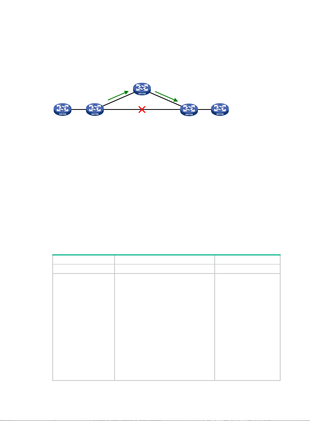
•
•
•
•
•
•
Step
Command
Remarks
Configure static route
] ] ]
] ] ]
tag
description
By default, static route FRR
Router A
Router B Router E
Backup nexthop:
Router C
Nexthop:
Router D
Configuring static route FRR
A link or router failure on a path can cause packet loss and even routing loop. Static route fast reroute
(FRR) enables fast rerouting to minimize the impact of link or node failures.
Figure 1 Network diagram
As shown in Figure 1, upon a link failure, packets are directed to the backup next hop to avoid traffic
interruption. Y ou can either specify a backup next hop for FRR or enable FRR to automatically select
a backup next hop (which must be configured in advance).
Configuration guidelines
Do not use static route FRR and BFD (for a static route) at the same time.
Static route does not take effect when the backup output interface is unavailable.
Equal-cost routes do not support static route FRR.
The backup output interface and next hop must be different from the primary output interface
To change the backup output interface or next hop, you must first remove the current setting.
Static route FRR is available only when the state of primary link (with Layer 3 interfaces staying
Configuring static route FRR by specifying a backup next hop
1. Enter system view.
2.
and next hop.
up) changes from bidirectional to unidirectional or down.
system-view
• Method 1:
ip route-static dest-address
{ mask-length | mask } interface-type
interface-number [ next-hop-address
[ backup-interface interface-type
interface-number [ backup-nexthop
backup-nexthop-address
[ permanent ] [ preference preference ]
[ tag tag-value ] [ description text ]
FRR.
• Method 2:
ip route-static vpn-instance
s-vpn-instance-name dest-address
{ mask-length | mask } interface-type
interface-number [ next-hop-address
[ backup-interface interface-type
interface-number [ backup-nexthop
backup-nexthop-address
[ permanent ] [ preference preference ]
[
tag-value ] [
text ]
N/A
is disabled.
12
Page 25

Step
Command
Remarks
system-view
FRR is
Step
Command
Remarks
Configure the source IP
address of BFD echo
echo packets is not
High Availability
Enable BFD echo packet
By default, BFD echo mode for
Task
Command
Display static route next hop
ing table
Configuring static route FRR to automatically select a backup next hop
1. Enter system view.
2. Configure static route FRR to
automatically select a
backup next hop.
ip route-static fast-reroute auto
N/A
By default, static route
disabled from automatically
selecting a backup next hop.
Enabling BFD echo packet mode for static route FRR
By default, static route F RR uses ARP to detec t primary link f ailures. Perform this task to enable
static route FRR to use BFD echo packet mode for fast failure detection on the primary link.
To enable BFD echo packet mode for static route FRR:
1. Enter system view.
2.
packets.
system-view
bfd echo-source-ip
ip-address
N/A
By default, the source IP address
of BFD
configured.
The source IP address cannot be
on the same network segment as
any local interface's IP address.
For more information about this
command, see
Command Reference.
3.
mode for static route FRR.
ip route-static
primary-path-detect bfd echo
static route FRR is disabled.
Displaying and maintaining static routes
Execute display commands in any view.
Display static route information.
information.
Display static rout
information.
display ip routing-table protocol static
display route-static nib
display route-static routing-table
vpn-instance-name ] [ ip-address { mask-length | mask } ]
[ nib-id ] [
[
verbose ]
inactive
[
verbose ]
|
vpn-instance
13
Page 26
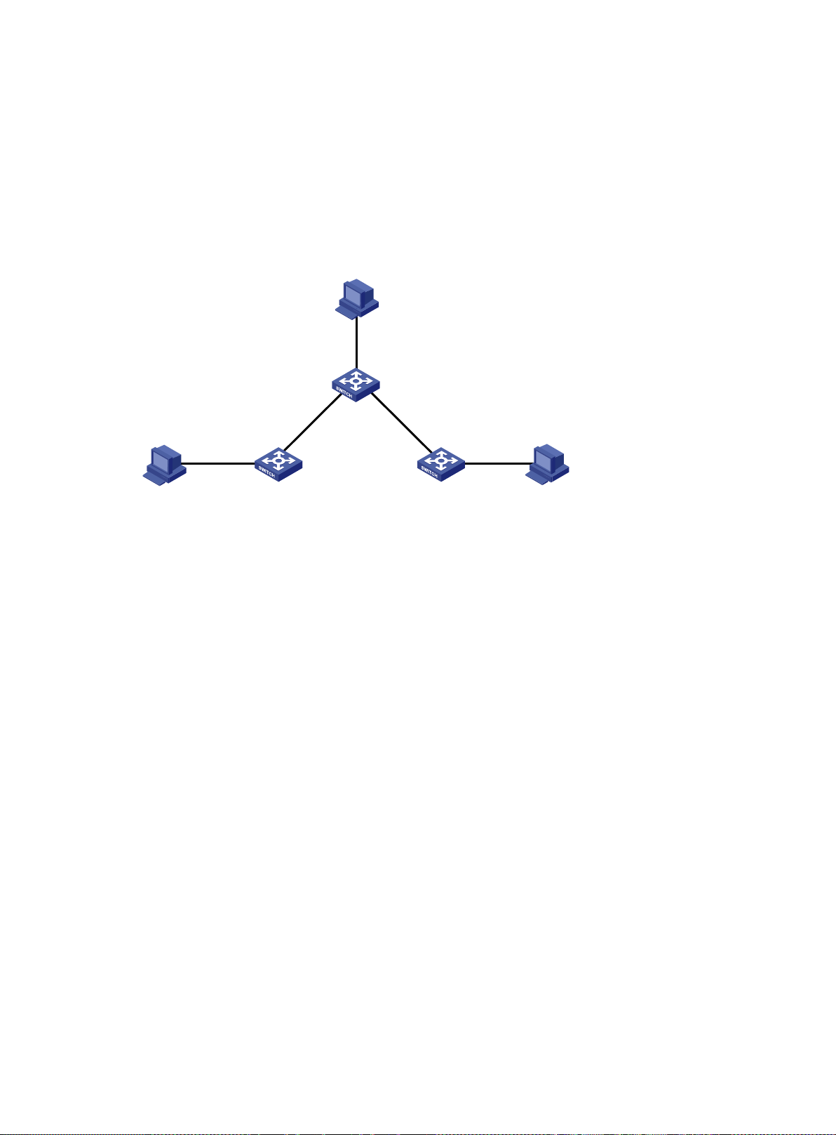
Vlan-int100
1.1.6.1/24
Host B
1.1.6.2/24
Vlan-int500
1.1.4.2/30
Vlan-int600
1.1.5.5/30
Vlan-int500
1.1.4.1/30
Vlan-int600
1.1.5.6/30
Vlan-int900
1.1.3.1/24
Vlan-int300
1.1.2.3/24
Host A
1.1.2.2/24
Host C
1.1.3.2/24
Switch B
Switch A
Switch C
Static route configuration examples
Basic static route configuration example
Network requirements
As shown in Figure 2, c onf i gure s tat ic routes on th e switches for interc onnections between an y t wo
hosts.
Figure 2 Network diagram
Configuration procedure
1. Configure IP addresses for interfaces. (Details not shown.)
2. Configure static routes:
# Configure a default route on Switch A.
<SwitchA> system-view
[SwitchA] ip route-static 0.0.0.0 0.0.0.0 1.1.4.2
# Configure two static routes on Switch B.
<SwitchB> system-view
[SwitchB] ip route-static 1.1.2.0 255.255.255.0 1.1.4.1
[SwitchB] ip route-static 1.1.3.0 255.255.255.0 1.1.5.6
# Configure a default route on Switch C.
<SwitchC> system-view
[SwitchC] ip route-static 0.0.0.0 0.0.0.0 1.1.5.5
3. Configure the default gateways of Host A, Host B, and Host C as 1.1.2.3, 1.1.6.1, and 1.1.3.1.
(Details not shown.)
Verifying the configuration
# Display static routes on Switch A.
[SwitchA] display ip routing-table protocol static
Summary Coun t : 1
Static Routing table Status : <Ac ti ve>
Summary Coun t : 1
14
Page 27

Destination/M ask Proto Pre Cost NextHop Interface
0.0.0.0/0 Static 60 0 1.1.4.2 Vlan500
Static Routing ta ble Status : <Inac tive>
Summary Coun t : 0
# Display static routes on Switch B.
[SwitchB] display ip routing-table protocol static
Summary Coun t : 2
Static Routing table Status : <Ac ti ve>
Summary Coun t : 2
Destination/Mask Proto Pre Cost NextHop Interface
1.1.2.0/24 Static 60 0 1.1.4.1 Vlan500
Static Routing table Status : <In ac tive>
Summary Coun t : 0
# Use the ping command on Host B to test the reachability of Host A (Windows XP runs on the two
hosts).
C:\Documents an d Settings\Administrator>ping 1.1.2.2
Pinging 1.1.2.2 with 32 bytes of data :
Reply from 1.1.2.2: bytes=32 time=1ms TTL=126
Reply from 1.1 .2.2: bytes=32 tim e=1ms TTL=126
Reply from 1.1 .2.2: bytes=32 tim e=1ms TTL=126
Reply from 1.1 .2.2: bytes=32 tim e=1ms TTL=126
Ping statist ics for 1.1.2.2:
Packets: Sent = 4, Received = 4, Lost = 0 (0% loss),
Approximat e round trip times in milli-seconds:
Minimum = 1ms, Maximum = 1ms, Average = 1ms
# Use the tracert command on Host B to test the reachability of Host A.
C:\Documents an d Settings\Administrator>tracert 1.1.2.2
Tracing rout e to 1.1.2.2 over a maxi mum of 30 hops
1 <1 ms <1 ms <1 ms 1.1.6.1
2 <1 ms <1 ms <1 ms 1.1.4.1
3 1 ms <1 ms <1 ms 1.1.2.2
Trace complete.
BFD for static routes configuration ex am ple (direct next hop)
Network requirements
Configure the following, as shown in Figure 3:
15
Page 28
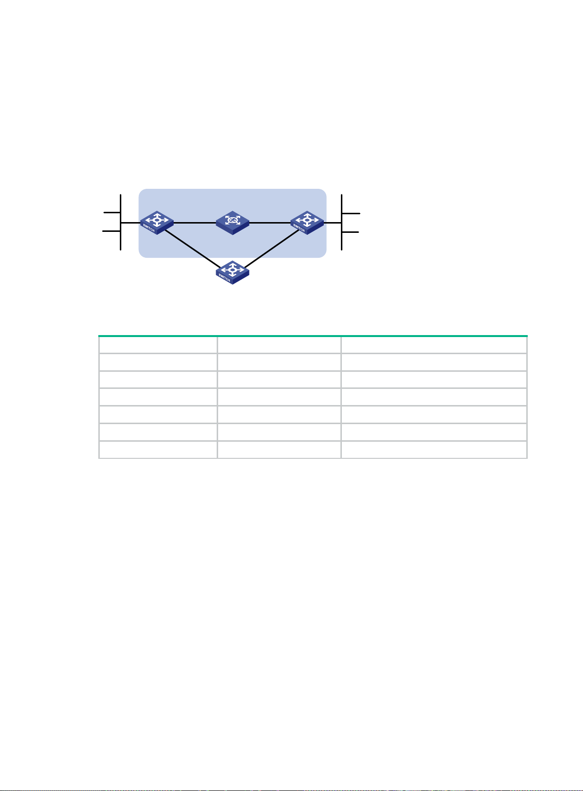
•
•
•
•
Device
Interface
IP address
Switch A Switch B
Switch C
BFD
L
2
Switch
Vlan-int10
Vlan
-int
11
Vlan-int11
Vlan
-int
13
Vlan-
int13
Vlan-int10
121.
1
.1
.0
/
24
120.1.1.0/24
Configure a static route to subnet 120.1.1.0/24 on Switch A.
Configure a static route to subnet 121.1.1.0/ 24 on S wit c h B.
Enable BFD for both routes.
Configure a static route to subnet 120.1.1.0/24 and a static route to subnet 121.1.1.0/24 on
Switch C.
When the link between Switch A and Switch B throu gh the Layer 2 switch fails, B FD c an det ec t th e
failure immediately. Switch A then communicates with Switch B through Switch C.
Figure 3 Network diagram
Table 4 Interface and IP address assignment
Switch A VLAN-interface 10 12.1.1.1/24
Switch A VLAN-interface 11 10.1.1.102/24
Switch B VLAN-interface 10 12.1.1.2/24
Switch B VLAN-interface 13 13.1.1.1/24
Switch C VLAN-interface 11 10.1.1.100/24
Switch C VLAN-interface 13 13.1.1.2/24
Configuration procedure
1. Configure IP addresses for the interfaces. (Details not shown.)
2. Configure static routes and BFD:
# Configure static routes on Switch A and enable BFD control mode for the static route that
traverses the Layer 2 switch.
<SwitchA> system-view
[SwitchA] interface vlan-interface 10
[SwitchA-vlan-interface10] bfd min-transmit-interval 500
[SwitchA-vlan-interface10] bfd min-receive-interval 500
[SwitchA-vlan-interface10] bfd detect-multiplier 9
[SwitchA-vlan-interface10] quit
[SwitchA] ip route-static 120.1.1.0 24 vlan-interface 10 12.1.1.2 bfd control-packet
[SwitchA] ip route-static 120.1.1.0 24 vlan-interface 11 10.1.1.100 preference 65
[SwitchA] quit
# Configure static routes on Switch B and enable BFD control mode for the static route that
traverses the Layer 2 switch.
<SwitchB> sy stem-view
[SwitchB] interface vlan-interface 10
16
Page 29

[SwitchB-vlan-interface10] bfd min-transmit-interval 500
[SwitchB-vlan-interface10] bfd min-receive-interval 500
[SwitchB-vlan-interface10] bfd detect-multiplier 9
[SwitchB-vlan-interface10] quit
[SwitchB] ip route-static 121.1.1.0 24 vlan-interface 10 12.1.1.1 bfd control-packet
[SwitchB] ip route-static 121.1.1. 0 24 vlan-interface 13 13.1.1.2 preference 65
[SwitchB] qu it
# Configure static routes on Switch C.
<SwitchC> sy stem-view
[SwitchC] ip rout e-static 120.1.1.0 24 13.1.1.1
[SwitchC] ip rout e-static 121.1.1.0 24 10.1.1.102
Verifying the configuration
# Display BFD sessions on Switch A.
<SwitchA> display bfd session
Total Session Nu m: 1 Up Session Num: 1 Init Mode: Ac tive
IPv4 Session Working Under Ctrl Mode:
LD/RD SourceAddr DestAddr State Holdtime Interface
4/7 12.1.1.1 12.1.1.2 Up 2000ms Vlan10
The output shows that the BFD session has been created.
# Display the static routes on Switch A.
<SwitchA> display ip routing-table protocol static
Summary Count : 1
Static Routing table Status : <Ac ti ve>
Summary Coun t : 1
Destination/Mask Proto Pre Cost NextHop Interface
120.1.1.0/24 Static 60 0 12. 1.1.2 Vlan10
Static Routing ta ble Status : <Inac tive>
Summary Count : 0
The output shows that Swit ch A communicates with Sw itch B thr ough VLAN-interface 10. Then the
link over VLAN-interface 10 fails.
# Display static routes on Switch A.
<SwitchA> display ip routing-table protocol static
Summary Coun t : 1
Static Routing table Status : <Ac ti ve>
Summary Coun t : 1
Destination/Mask Proto Pre Cost NextHop Interface
120.1.1.0/24 Static 65 0 10. 1.1.100 Vlan11
17
Page 30
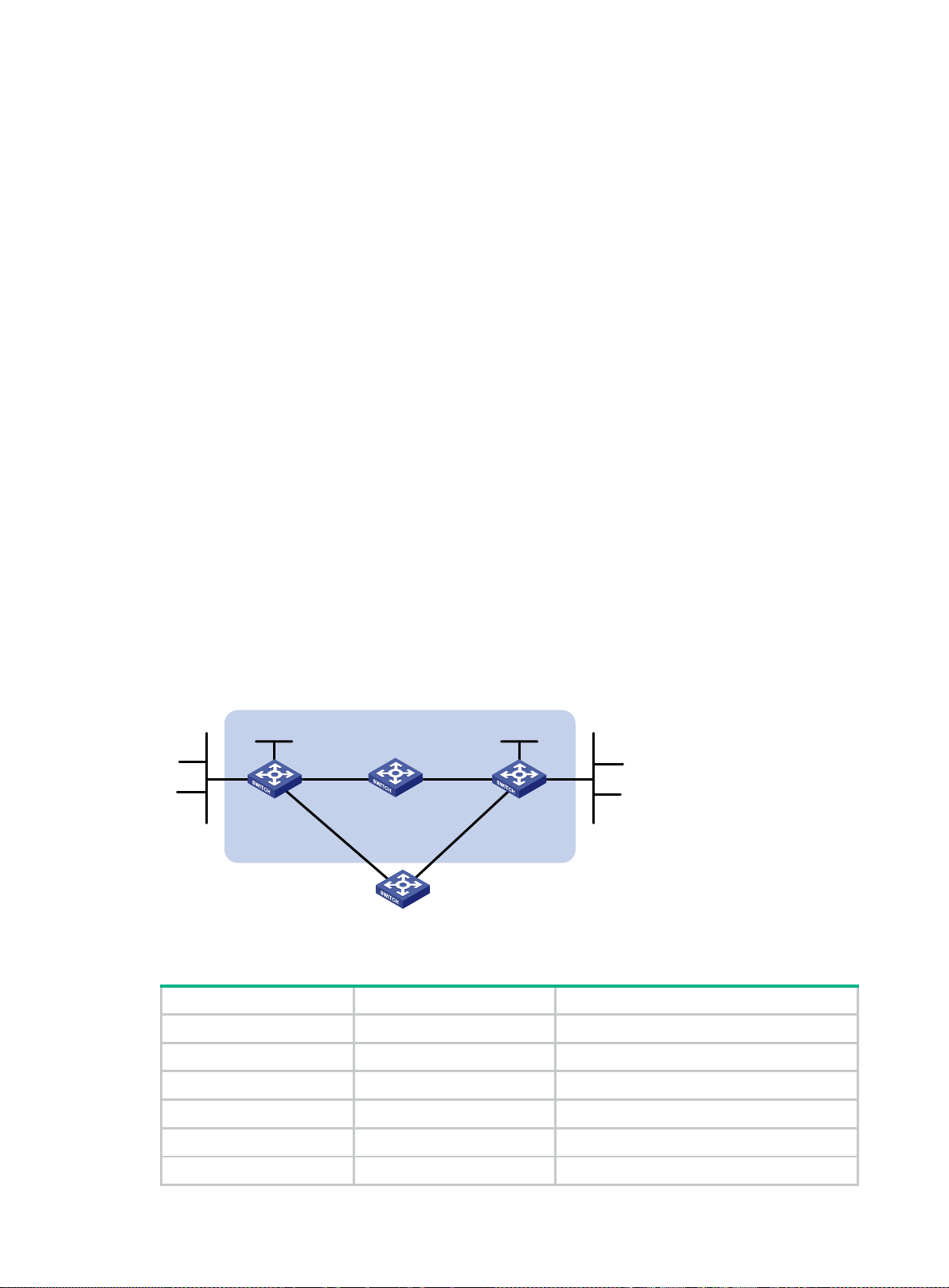
•
•
•
•
•
•
•
Device
Interface
IP address
Switch A Switch B
Switch C
BFD
Vlan-int10
Vlan
-
int
11
Vlan-int11 Vlan-int13
Vlan-
int
13
Vlan-int10
121.1.1.0/24
120.1.1.0/24
Switch D
Vlan-int12
Vlan-int12
Loop1
1.1.1.9/32
Loop1
2.2.2.9/32
Static Routing ta ble Status : <Inac tive>
Summary Coun t : 0
The output shows that Switch A communicates with Switch B through VLAN-interface 11.
BFD for static routes configuration ex am ple (indirect next hop)
Network requirements
Figure 4 shows the network topology as follows:
Switch A has a route to interface Loopback 1 (2.2.2.9/32) on Switch B, with the output interface
VLAN-interface 10.
Switch B has a route to interface Loopback 1 (1.1.1.9/32) on Switch A, with the output interface
VLAN-interface 12.
Switch D has a route to 1.1.1.9/32, with the output interface VLAN-interface 10, and a route to
2.2.2.9/32, with the output interfac e VLAN-interface 12.
Configure the following:
Configure a static route to subnet 120.1.1.0/24 on Switch A.
Configure a static route to subnet 121.1.1.0/24 on Switch B.
Enable BFD for both routes.
Configure a static route to subnet 120.1.1.0/24 and a static route to subnet 121.1.1.0/24 on both
Switch C and Switch D.
When the link between Switch A and Switch B through Switch D fails, BFD can detect the failure
immediately. Switch A then communicates with Switch B through Switch C.
Figure 4 Network diagram
Table 5 Interface and IP address assignment
Switch A VLAN-interface 10 12.1.1.1/24
Switch A VLAN-interface 11 10.1.1.102/24
Switch A Loopback 1 1.1.1.9/32
Switch B VLAN-interface 12 11.1.1.1/24
Switch B VLAN-interface 13 13.1.1.1/24
Switch B Loopback 1 2.2.2.9/32
18
Page 31

Device
Interface
IP address
Switch C VLAN-interface 11 10.1.1.100/24
Switch C VLAN-interface 13 13.1.1.2/24
Switch D VLAN-interface 10 12.1.1.2/24
Switch D VLAN-interface 12 11.1.1.2/24
Configuration procedure
1. Configure IP addresses for interfaces. (Details not shown.)
2. Configure static routes and BFD:
# Configure static routes on Switch A and enable BFD control mode for the static route that
traverses Switch D.
<SwitchA> system-view
[SwitchA] bf d multi-hop min-transmit-interval 500
[SwitchA] bf d multi-hop min-receive-interval 500
[SwitchA] bfd multi-hop detect-multiplier 9
[SwitchA] ip route-static 120.1.1.0 24 2.2.2.9 bfd control-packet bfd-source 1.1.1.9
[SwitchA] ip route-static 120.1.1.0 24 vlan-interface 11 10.1.1.100 preference 65
[SwitchA] quit
# Configure static routes on Switch B and enable BFD control mode for the static route that
traverses Switch D.
<SwitchB> sy stem-view
[SwitchB] bfd multi-hop min-transmit-interval 500
[SwitchB] bfd multi-hop min-receive-interval 500
[SwitchB] bfd multi-hop detect-multiplier 9
[SwitchB] ip route-static 121.1.1.0 24 1.1.1.9 bfd control-packet bfd-source 2.2.2.9
[SwitchB] ip route-static 121.1.1. 0 24 vlan-interface 13 13.1.1.2 preference 65
[SwitchB] qu it
# Configure static routes on Switch C.
<SwitchC> sy stem-view
[SwitchC] ip rout e-static 120.1.1.0 24 13.1.1.1
[SwitchC] ip rout e-static 121.1.1.0 24 10.1.1.102
# Configure static routes on Switch D.
<SwitchD> sy stem-view
[SwitchD] ip rout e-static 120.1.1.0 24 11.1.1.1
[SwitchD] ip rout e-static 121.1.1.0 24 12.1.1.1
Verifying the configuration
# Display BFD sessions on Switch A.
<SwitchA> display bfd session
Total Session Nu m: 1 Up Session Num: 1 Init Mode: Ac tive
IPv4 Session Working Under Ctrl Mode:
LD/RD SourceAddr DestAddr State Holdtime Interf ace
4/7 1.1.1.9 2.2.2.9 Up 2000ms N/A
The output shows that the BFD session has been created.
19
Page 32

Switch A Switch B
Switch C
Loop0
Vlan-int100
Vlan-
int200
Vlan-int200
Vlan-int100
Vlan
-int101
Vlan-int101
Loop0
Link A
Link B
# Display the static routes on Switch A.
<SwitchA> display ip routing-table protocol static
Summary Coun t : 1
Static Routing table Status : <Ac ti ve>
Summary Coun t : 1
Destination/Mask Proto Pre Cost NextHop Interface
120.1.1.0/24 Static 60 0 12.1.1.2 Vlan10
Static Routing ta ble Status : <Inac tive>
Summary Coun t : 0
The output shows that Swit ch A communicates with Sw itch B thr ough VLAN-interface 10. Then the
link over VLAN-interface 10 fails.
# Display static routes on Switch A.
<SwitchA> display ip routing-table protocol static
Summary Coun t : 1
Static Routing table Status : <Ac ti ve>
Summary Coun t : 1
Destination/Mask Proto Pre Cost NextHop Interface
120.1.1.0/24 Static 65 0 10. 1.1.100 Vlan11
Static Routing ta ble Status : <Inac tive>
Summary Coun t : 0
The output shows that Switch A communicates with Switch B through VLAN-interface 11.
Static route FRR configuration example
Network requirements
As shown in Figure 5, conf igure static routes on Switch A, Switch B, and Switch C, and configure
static route FRR. When Link A becomes unidirectional, traffic can be switched to Link B immediately.
Figure 5 Network diagram
20
Page 33

Device
Interface
IP address
Table 6 Interface and IP address assignment
Switch A VLAN-interface 100 12.12.12.1/24
Switch A VLAN-interface 200 13.13.13.1/24
Switch A Loopback 0 1.1.1.1/32
Switch B VLAN-interface 101 24.24.24.4/24
Switch B VLAN-interface 200 13.13.13.2/24
Switch B Loopback 0 4.4.4.4/32
Switch C VLAN-interface 100 12.12.12.2/24
Switch C VLAN-interface 101 24.24.24.2/24
Configuration procedure
1. Configure IP addresses for interfaces. (Details not shown.)
2. Configure static route FRR on link A by using one of the following methods:
(Method 1.) Specify a backup next hop for static route FRR:
# Configure a static route on Switch A, and specify VLAN-interface 100 as the backup
output interface and 12.12.12.2 as the backup next hop.
<SwitchA> system-view
[SwitchA] ip route-static 4.4.4.4 32 vlan-interfa ce 200 13.13.13.2
backup-interface vlan-interface 100 backup-nexthop 12.12.12.2
# Configure a static route on Switch B, and specify VLAN-interface 101 as the backup
output interface and 24.24.24.2 as the backup next hop.
<SwitchB> system-view
[SwitchB] ip route-static 1.1.1.1 32 vlan-interfa ce 200 13.13.13.1
backup-interface vlan-interface 101 backup-nexthop 24.24.24.2
(Method 2.) Configure static route FRR to automatically select a backup next hop:
# Configure static routes on Switch A, and enable static route FRR.
<SwitchA> system-view
[SwitchA] ip route-static 4.4.4.4 32 vlan-interface 20 0 13.13.13.2
[SwitchA] ip route-static 4.4.4.4 32 vl an-interface 100 12.12. 12.2 preference 70
[SwitchA] ip route-static fast-reroute auto
# Configure static routes on Switch B, and enable static route FRR.
<SwitchB> system-view
[SwitchB] ip route-static 1.1.1.1 32 vlan-interfac e 200 13.13.13.1
[SwitchB] ip route-static 1.1.1.1 32 vl an-interface 101 24.24.24.2 preference 70
[SwitchB] ip route-static fast-reroute auto
3. Configure static routes on Switch C.
<SwitchC> system-view
[SwitchC] ip route-static 4.4.4.4 32 vlan-interfa ce 101 24.24.24.4
[SwitchC] ip route-static 1.1.1.1 32 vlan-interfa ce 100 12.12.12.1
Verifying the configuration
# Display route 4.4.4.4/32 on Switch A to view the backup next hop information.
[SwitchA] display ip routing-table 4.4.4.4 verbose
Summary Coun t : 1
21
Page 34

Destination: 4. 4.4.4/32
Protocol: Static
Process ID: 0
SubProtID: 0x0 Age: 04h20m37s
Cost: 0 Preference: 60
IpPre: N/A QosLocalID: N/A
Tag: 0 State: Active Adv
OrigTblID: 0x0 OrigVrf: default-vrf
TableID: 0x2 OrigAs: 0
NibID: 0x 26000002 LastAs: 0
AttrID: 0x ffffffff Neighbor: 0.0. 0.0
Flags: 0x1008c OrigNextHop: 13.13.13.2
Label: NULL RealNextHop: 13.13.13.2
BkLabel: NULL BkNextHop: 12.12.12.2
Tunnel ID: Inva lid Interface: Vlan-interface200
BkTunnel ID: Inva lid BkInterface: Vlan -interface100
FtnIndex: 0x0 TrafficIndex: N/A
Connector: N/A
# Display route 1.1.1.1/32 on Switch B to view the backup next hop information.
[SwitchB] display ip routing-table 1.1.1.1 verbose
Summary Count : 1
Destination: 1.1.1.1/32
Protocol: Static
Process ID: 0
SubProtID: 0x0 Age: 04h20m37s
Cost: 0 Preference: 60
IpPre: N/A QosLocalID: N/A
Tag: 0 State: Active Adv
OrigTblID: 0x0 OrigVrf: default-vrf
TableID: 0x2 OrigAs: 0
NibID: 0x 26000002 LastAs: 0
AttrID: 0x ffffffff Neighbor: 0.0. 0.0
Flags: 0x1008c OrigNextHop: 13.13.13.1
Label: NULL RealNextHop: 13.13.13.1
BkLabel: NULL BkNextHop: 24.24.24.2
Tunnel ID: Inva lid Interface: Vlan-interface200
BkTunnel ID: Inva lid BkInterface: Vlan-interface101
FtnIndex: 0x0 TrafficIndex: N/A
Connector: N/A
22
Page 35

•
•
Configuring a default route
A default route is used to forward packets that do not match any specific routing entry in the routing
table. Without a default route, packets that do not match any routing entries are discarded.
A default route can be configured in either of the following ways:
The network administrator can configure a default r out e with both des ti nat ion an d mask being
0.0.0.0. For more information, see "Configuring static routing."
Some dynamic routing protocols, such as OSPF, IS-IS, and RIP, can generate a default route.
For example, an upstream router running OSPF can generate a default route and advertise it to
other routers. These routers install the default route with the next hop being the upstream router.
For more information, see the respective chapters on these routing protocols in this
configuration guide.
23
Page 36

•
•
•
•
•
•
•
•
•
•
Configuring RIP
Overview
Routing Information Protocol (RIP) is a distance-vector IGP suited to small-sized networks. It
employs UDP to exchange route inform ation through port 520.
RIP uses a hop count to meas ure the distance to a d estination. The hop c ount from a router to a
directly connected net work is 0. T he hop count from a r outer to a direc tly connect ed router is 1. To
limit convergence tim e, RI P restr icts the val ue ran ge of t he metric from 0 to 15. A destination with a
metric value of 1 6 (or greater) is considered unreachabl e. For this reason, RI P is not suitable f or
large-sized networks.
RIP route entries
RIP stores routing entries in a database. Each routing entry contains the following elements:
Destination address—IP address of a destination host or a network.
Next hop—IP address of the next hop.
Egress interface—Egress interface of the route.
Metric—Cost from the local router to the destination.
Route time—Time elapsed since the last update. The time is reset to 0 when the routing entry
is updated.
Route tag—Used for route control. For more information, see "Configuring routing policies."
Routing loop prevention
RIP uses the following mechanisms to prevent routing loops:
Counting to infinity—A destination with a metric value of 16 is considered unreachable. When
a routing loop occurs, the metric value of a route will increment to 16 to avoid endless looping.
Triggered updates—RIP immediately advertises triggered updates for topology changes to
reduce the possibility of routing loops and to speed up convergence.
Split horizon—Disables RIP from sending routes through the interface where the routes were
learned to prevent routing loops and save bandwidth.
Poison reverse—Enables RIP to set the metric of routes received from a neighbor to 16 and
sends these routes back to the neighbor. The neighbor can delete such information from its
routing table to prevent routing loops.
RIP operation
RIP works as follows:
1. RIP sends request messages to neighboring routers. Neighboring routers return response
messages that contain their routing tables.
2. RIP uses the received responses to update the local routing table and sends triggered update
messages to its neighbors. All RIP routers on the network do this to learn latest routing
information.
3. RIP periodically sends the local routing table to its neighbors. After a RIP neighbor receives the
message, it updates its routing table, selects optimal routes, and sends an update to other
neighbors. RIP ages routes to keep only valid routes.
24
Page 37

•
•
•
•
•
•
•
•
•
•
•
•
Tasks at a glance
RIP versions
There are two RIP versions, RIPv1 and RIPv2.
RIPv1 is a classful routing protocol. It advertises messages only through broadcast. RIPv1
messages do not car ry mask information, so RIPv1 c an only recognize natura l networks such as
Class A, B, and C. For this reason, RIPv1 does not support discontiguous subnets.
RIPv2 is a classless routing protocol. It has the following advantages over RIPv1:
Supports route tags to implement flexible route control through routing policies.
Supports masks, route summarization, and CIDR.
Supports designated next hops to select the best ones on broadcast networks.
Supports multicasting route updates so only RIPv2 routers can receive these updates to reduce
resource consumption.
Supports plain text authentication and MD5 authentication to enhance security.
RIPv2 supports two transm ission modes: broadcast and multicas t. Multicast is the default mode
using 224.0.0.9 as the multicast address. An interface operating in RIPv2 broadcast mode can also
receive RIPv1 messages.
Protocols and standards
RFC 1058, Routing Information Protocol
RFC 1723, RIP Version 2 - Carrying Additional Information
RFC 1721, RIP Version 2 Protocol Analysis
RFC 1722, RIP Version 2 Protocol Applicability Statement
RFC 1724, RIP Version 2 MIB Extension
RFC 2082, RIPv2 MD5 Authentication
RFC 2453, RIP Version 2
RIP configuration task list
Configuring basic RIP:
• (Required.) Enabling RIP
• (Optional.) Controlling RIP reception and advertisement on interfaces
• (Optional.) Configuring a RIP version
(Optional.) Configuring RIP route control:
• Configuring an additional routing metric
• Configuring RIPv2 route summarization
• Disabling host route reception
• Advertising a default route
• Configuring received/redistributed route filtering
• Setting a preference for RIP
• Configuring RIP route redistribution
25
Page 38

•
•
•
•
•
•
•
Step
Command
Remarks
RIP and enter RIP
(Optional.) Tuning and optimizing RIP networks:
• Setting RIP timers
• Enabling split horizon and poison reverse
• Setting the maximum number of RIP ECMP routes
• Enabling zero field check on incoming RIPv1 messa ges
• Enabling source IP address check on incomi ng RIP updates
• Configuring RIPv2 message authentication
• Setting the RIP triggered update interval
• Specifying a RIP neighbor
• Configuring RIP network management
• Configuring the RIP packet sending rate
• Setting the maximum length of RIP packets
• Setting the DSCP value for outgoing RIP packets
(Optional.) Configuring RIP GR
(Optional.) Enabling RIP NSR
(Optional.) Configuring BFD for RIP
(Optional.) Configuring RIP FRR
Configuring basic RIP
Before you configure basic RIP settings, complete the following tasks:
Configure the link layer protocol.
Configure IP addresses for interfaces to ensure IP connectivity between neighboring routers.
Enabling RIP
Follow these guidelines when you enable RIP:
To enable multiple RIP processes on a router, you must specify an ID for each process. A RIP
process ID has only local significance. Two RIP routers having different process IDs can also
exchange RIP packets.
If you configure RIP settings in interface view before enabling RIP, the settings do not take
effect until RIP is enabled.
If a physical interface is attached to multiple networks, you cannot advertise these networks in
different RIP processes.
You cannot enable multiple RIP processes on a physical interface.
The rip enable command takes precedence over the network command.
Enabling RIP on a network
You can enable RIP on a network and specif y a wildc ard m ask for the net work. Af ter that, on ly the
interface attached to the network runs RIP.
To enable RIP on a network:
1. Enter system view.
2. Enable
view.
system-view
rip
[ process-id ] [
vpn-instance-name ]
26
vpn-instance
N/A
By default, RIP is disabled.
Page 39

Step
Command
Remarks
, but does not
Step
Command
Remarks
RIP and enter RIP
exclude-subip
Step
Command
Remarks
interface from
The disabled interface can still
messages and
respond to unicast requests
interface to
interface to send
interface can send RIP
3. Enable RIP on a network.
Enabling RIP on an interface
network
[ wildcard-mask ]
network-address
By default, RIP is disabled on a
network.
network
The
can enable RIP on al l interf aces i n
a single process
apply to multiple RIP processes.
0.0.0.0 command
1. Enter system view.
2. Enable
view.
3. Return to system view.
4. Enter interface view.
5. Enable RIP on the interface.
system-view
rip
[ process-id ] [
vpn-instance-name ]
quit
interface
interface-number
rip
[
interface-type
process-id
]
vpn-instance
enable
N/A
By default, RIP is disabled.
N/A
N/A
By default, RIP is disabled on an
interface.
Controlling RIP reception and adverti sement on interfaces
1. Enter system view.
2. Enter RIP view.
3. Disable an
sending RIP messages.
system-view
rip
[ process-id ] [
vpn-instance-name ]
silent-interface
interface-number |
{ interface-type
all
vpn-instance
}
N/A
N/A
By default, all RIP-enabled
interfaces can send RIP
messages.
receive RIP
4. Return to system view.
5. Enter interface view.
6. Enable an
receive RIP messages.
7. Enable an
RIP messages.
Configuring a RIP version
You can configure a global RIP version in RI P view or an interface-specif ic RI P version in interface
view.
quit
interface
interface-number
rip input
rip output
interface-type
27
containing unknown ports.
N/A
N/A
By default, a RIP-enabled
interface can receive RIP
messages.
By default, a RIP-enabled
messages.
Page 40

•
•
Step
Command
Remarks
system-view
, no global version is
interface sends
RIPv1 broadcasts, and can
RIPv2 broadcasts,
specified. The
interface sends RIPv1
broadcasts, and can receive
•
•
Step
Command
Remarks
An interface preferent ially us es the interf ace-spec ific RIP version. If no interf ace-spe cific versio n is
specified, the inter face uses the global RIP version. If neither a global nor interfac e-specific RIP
version is configured, the interface sends RIPv1 broadcasts and can receive the following:
RIPv1 broadcasts and unicasts.
RIPv2 broadcasts, multicasts, and unicasts.
To configure a RIP version:
1. Enter system view.
2. Enter RIP view.
3. Specify a global RIP version.
4. Return to system view.
5. Enter interface view.
6. Specify a RIP version for the
interface.
rip
[ process-id ] [
vpn-instance-name ]
version
quit
interface
interface-number
rip version
multicast
{ 1 | 2 }
interface-type
{ 1 | 2 [
] }
vpn-instance
broadcast
Configuring RIP route control
N/A
N/A
By default
specified. An
receive RIPv1 broadcasts and
unicasts, and
multicasts, and unicasts.
N/A
N/A
By default, no interface-specific
RIP version is
|
RIPv1 broadcasts and unicasts,
and RIPv2 broad casts, multi casts,
and unicasts.
Before you configure RIP route control, complete the following tasks:
Configure IP addresses for interfaces to ensure IP connectivity between neighboring routers.
Configure basic RIP.
Configuring an add i tional routing metric
An additional routing m etric ( hop count) c an be ad ded to the metr ic of an inbound or outbound RIP
route.
An outbound additional metric is added to the metric of a sent route, and it does not c hange the
route's metric in the routing table.
An inbound additional metric is added to the metric of a received route before the route is added into
the routing table, and the route's metric is changed. If the sum of the addition al metric and the
original metric is greater than 16, the metric of the route is 16.
To configure additional routing metrics:
1. Enter system view.
system-view
28
N/A
Page 41

Step
Command
Remarks
Step
Command
Remarks
automatic route
Step
Command
Remarks
Disable RIPv2 automatic
2. Enter interface view.
3. Specify an inbound
additional routing metric.
4. Specify an outbound
additional routing metric.
interface
interface-number
rip metricin
route-policy-name ] value
rip metricout
route-policy-name ] value
interface-type
route-policy
[
route-policy
[
Configuring RI P v2 route summarization
Perform this task to summarize contiguous subnets into a summary network and sends the network
to neighbors. The smallest metric among all summarized routes is used as the metric of the
summary route.
Enabling RIPv2 automatic route summarization
Automatic summarization enables RIP v2 t o ge ner at e a natur a l net work for contiguous subnets. F or
example, suppose there are three subnet routes 10.1.1.0/24, 10.1.2.0/24, and 10.1.3.0/24.
Automatic summ ar ization a utomatically creates and advertises a summ ar y route 1 0.0.0 . 0/8 inste ad
of the more specific routes.
To enable RIPv2 automatic route summarization:
1. Enter system view.
system-view
N/A
The default setting is 0.
The default setting is 1.
N/A
2. Enter RIP view.
3. (Optional.) Enable RIPv2
summarization.
Advertising a summary route
Perform this task to manually configure a summary route.
For example, suppose cont iguous subne ts routes 10.1 .1.0/24, 10 .1. 2.0/2 4, and 1 0.1.3.0/2 4 exist in
the routing table. You can create a summ ary route 10.1.0.0/16 on Hundr edGigE 1/0/1 to advertise
the summary route instead of the more specific routes.
To configure a summary route:
1. Enter system view.
2. Enter RIP view.
3.
route summarization.
4. Return to system view.
rip
[ process-id ] [
vpn-instance-name ]
summary
system-view
rip
[ process-id ] [
vpn-instance-name ]
undo summary
quit
vpn-instance
vpn-instance
N/A
By default, RIPv2 automatic route
summarization is enabled.
If subnets in the routing table are
not contiguous, disable automatic
route summarization to advertise
more specific routes.
N/A
N/A
By default, RIPv2 automatic route
summarization is enabled.
N/A
5. Enter interface view.
interface
interface-number
29
interface-type
N/A
Page 42

Step
Command
Remarks
no summary route is
Step
Command
Remarks
from receiving
By default, RIP receives host
Step
Command
Remarks
system-view
Enable RIP to advertise a
Configure the RIP interface
By default, a RIP interface can
NOTE:
The router enabled to advertise a default route does not accept default routes from RIP neighbors.
6. Configure a summary route.
rip summary-address
ip-address
Disabling host r oute reception
Perform this task to disable RIPv2 from receiving host routes from the same network to save network
resources. This feature does not apply to RIPv1.
To disable RIP from receiving host routes:
1. Enter system view.
2. Enter RIP view.
3. Disable RIP
host routes.
system-view
rip
[ process-id ] [
vpn-instance-name ]
undo host-route
Advertising a def ault route
You can advertise a default route on all RIP interfaces in RIP view or on a specific RIP interf ace in
interface view. The interface view setting takes precedence over the RIP view settings.
{ mask-length | mask }
vpn-instance
By default,
configured.
N/A
N/A
routes.
To disable an interface from advertising a default route, use the rip default-route no-originate
command on the interface.
To configure RIP to advertise a default route:
1. Enter system view.
2. Enter RIP view.
3.
default route.
4. Return to system view.
5. Enter interface view.
6.
to advertise a default route.
rip
[ process-id ] [
vpn-instance-name ]
default-route
cost
[
cost-value |
route-policy-name ] *
quit
interface
interface-number
rip default-route
originate
route-policy
no-originate
* |
only
{
interface-type
{ {
cost
} [
route-policy-name ]
}
vpn-instance
originate
|
route-policy
only
cost-value |
N/A
N/A
}
By default, RIP does not adver tise
a default route.
N/A
N/A
|
advertise a default route if the RIP
process is enabled to advertise a
default route.
Configuring received/redistributed route filtering
Perform this task to filter received and redistributed routes by using a filtering policy.
30
Page 43

Step
Command
Remarks
Configure the filtering of
By default, the filtering of
command filters received
routes. Filtered routes are not
By default, the filtering of
redistributed routes is not
command filters
redistributed routes, including
routes redistributed with the
Step
Command
Remarks
Step
Command
Remarks
To configure route filtering:
1. Enter system view.
2. Enter RIP view.
3.
received routes.
4. Configure the filtering of
redistributed routes.
system-view
rip
[ process-id ] [
vpn-instance-name ]
filter-policy
gateway
prefix-list-name [
prefix-list-name ] }
[ interface-type interface-number ]
filter-policy
prefix-list
[ protocol [ process-id ] | interface-type
interface-number ]
prefix-list-name |
Setting a preference for RIP
If multiple IGPs find rou tes to the s ame destination, the r oute f oun d by the IGP that has the highest
priority is selected as the optimal route. Perform this task to assign a preference to RIP. The smaller
the preference value, the higher the priority.
vpn-instance
{ ipv4-acl-number |
prefix-list
gateway
import
{ ipv4-acl-number |
prefix-list-name }
export
N/A
N/A
received routes is not
configured.
This
installed into the routing table or
advertised to neighbors.
configured.
This
import-route
command.
To set a preference for RIP:
1. Enter system view.
2. Enter RIP view.
3. Set a preference for RIP.
system-view
rip
[ process-id ] [
vpn-instance-name ]
preference
route-policy
*
{ preference |
route-policy-name }
vpn-instance
Configuring RI P route redistribution
Perform this task to configure RIP to redistribute routes from other routing protocols, including OSPF ,
IS-IS, BGP, static, and direct.
To configure RIP route redistribution:
1. Enter system view.
2. Enter RIP view.
system-view
rip
[ process-id ] [
vpn-instance-name ]
vpn-instance
N/A
N/A
The default setting is 100.
N/A
N/A
31
Page 44

Step
Command
Remarks
s from
RIP route
This command can redistribute
display ip
•
•
•
•
•
•
IMPORTANT:
To avoid unnecessary traffic or route flapping, configure identical RIP timer settings on RIP routers.
Step
Command
Remarks
By default,
redistribution is disabled.
]
only active routes. To view active
routes, use the
routing-table
command.
The default setting is 0.
3. Redistribute route
another routing protocol.
4. (Optional.) Set a default cost
for redistributed routes.
import-route
[ as-number ] [ process-id |
all-processes
allow-direct
[
route-policy
tag
tag ] *
default cost
allow-ibgp
|
cost
|
route-policy-name |
cost-value
protocol
cost-value |
Tuning and optimizing RIP networks
Configuration prerequisites
Before you tune and optimize RIP networks, complete the following tasks:
Configure IP addresses for interfaces to ensure IP connectivity between neighboring nodes.
Configure basic RIP.
Setting RIP timers
You can change the RIP network convergence speed by adjusting the following RIP ti mers:
Update timer—Specifies the interval between route updates.
Timeout timer—Specifies the route aging time. If no update for a route is received within the
aging time, the metric of the route is set to 16.
Suppress timer—Specifies how long a RIP route stays in suppressed state. When the metric
of a route is 16, the route enters the suppressed state. A suppressed route can be replaced by
an updated route that is received from the same neighbor before the suppress timer expires
and has a metric less than 16.
Garbage-collect timer—Specifies the interval from when the metric of a route becomes 16 to
when it is deleted from the routing table. RIP advertises the route with a metric of 16. If no
update is announced for that route before the garbage-collect timer expires, the route is deleted
from the routing table.
protocol
To set RIP timers:
1. Enter system view.
2. Enter RIP view.
system-view
rip
[ process-id ] [
vpn-instance-name ]
32
vpn-instance
N/A
N/A
Page 45

Step
Command
Remarks
Step
Command
Remarks
, split horizon is
Step
Command
Remarks
Step
Command
Remarks
By default:
• The garbage-collect timer is 120
• The suppress timer is 120
• The timeout timer is 180 seconds.
• The update timer is 30 seconds.
3. Set RIP timers.
timers
garbage-collect-value |
suppress-value |
timeout-value |
update-value } *
garbage-collect
{
suppress
timeout
update
Enabling split horizon and poison reverse
The split horizon and poison reverse functions can prevent routing loops.
If both split horizon and poison reverse are configured, only the poison reverse function takes effect.
Enabling split horizon
Split horizon disables RIP from sending routes through the interface where the routes were learned
to prevent routing loops bet ween adjacent routers.
To enable split horizon:
seconds.
seconds.
1. Enter system view.
2. Enter interface view.
3. Enable split horizon.
system-view
interface
interface-number
rip split-horizon
interface-type
N/A
N/A
By default
enabled.
Enabling poison reverse
Poison reverse allows RIP to send routes through the interface where the routes were learned. The
metric of these routes is always set to 16 (unreachable) to avoid routing loops between neighbors.
To enable poison reverse:
1. Enter system view.
2. Enter interface view.
3. Enable poison reverse.
system-view
interface
interface-number
rip poison-reverse
interface-type
N/A
N/A
By default, poison reverse is
disabled.
Setting the maxim um number of RIP ECMP routes
Perform this task to implement load sharing over ECMP routes.
To set the maximum number of RI P ECMP routes:
1. Enter system view.
system-view
33
N/A
Page 46

Step
Command
Remarks
equals the
maximum number of ECMP
Step
Command
Remarks
Step
Command
Remarks
check on incoming RIP
By default, this function is
2. Enter RIP view.
3. Set the maximum number of
RIP ECMP routes.
rip
[ process-id ] [
vpn-instance-name ]
maximum load-balancing
number
vpn-instance
N/A
By default, the maximum number
of RIP ECMP routes
routes supported by the system.
Enabling zero field check on incoming RIPv1 messages
Some fields in the RIPv1 message must be set to zero. These fields are called "zero fields." Y ou can
enable zero field check on incoming RIPv1 messages. If a zero field of a message contains a
non-zero value, RIP does not process the message. If you are certain that all messages are
trustworthy, disable zero field check to save CPU resources.
This feature does not apply to RIPv2 packets, because they have no zero fields.
To enable zero field check on incoming RIPv1 messages:
1. Enter system view.
2. Enter RIP view.
3. Enable zero field check on
incoming RIPv1 messages.
system-view
rip
[ process-id ] [
vpn-instance-name ]
checkzero
vpn-instance
N/A
N/A
The default setting is enabled.
Enabling source IP address check on incoming RIP updates
Perform this task to enable source IP address check on incoming RIP updates.
Upon receiving a message on an Etherne t interface, RIP compares the source IP address of the
message with the IP addr ess of the interface. If the y are not in the same network segment, RIP
discards the message.
Upon receiving a message on a PPP interface, RIP checks whether the source address of the
message is the IP address of the peer interface. If not, RIP discards the message.
To enable source IP address check on incoming RIP updates:
1. Enter system view.
2. Enter RIP view.
3. Enable source IP address
messages.
system-view
rip
[ process-id ] [
vpn-instance-name ]
validate-source-address
vpn-instance
N/A
N/A
enabled.
Configuring RI P v2 message authent i c ation
Perform this task to enable authentication on RIPv2 messages. This feature does not apply to RIPv1
because RIPv1 does not support authentic ation. A lthough you can sp ecify an authent ication m ode
for RIPv1 in interface view, the configuration does not take effect.
34
Page 47

Step
Command
Remarks
By default, RIPv2
is not
•
•
Step
Command
Remarks
Set the RIP triggered
•
•
RIPv2 supports two authentication modes: simple authentication and MD5 authentication.
To configure RIPv2 message authentication:
1. Enter system view.
2. Enter interface view.
3. Configure RIPv2
authentication.
system-view
interface
rip authentication-mode
cipher
{
cipher
{
plain }
interface-type interface-number
plain
|
plain
|
string }
} string key-id |
} string } |
md5
{
{
simple { cipher
Setting the RIP t riggered update inter v al
Perform this task to avoid network overh ead and r educe system resource cons umption caused by
frequent RIP triggered updates.
You can use the timer triggered comm and to set the maximum interval, minimum interva l, and
incremental interval for sending RIP triggered updates.
For a stable network, the minimum-interval is used.
If network changes become frequent, the incremental interval incremental-interval is used to
extend the triggered update sending int er val unti l the maximum-interval is reached.
To set the triggered update interval:
1. Enter system view.
system-view
rfc2082
rfc2453
|
N/A
N/A
authentication
configured.
N/A
rip
2. Enter RIP view.
3.
update interval.
[ process-id ] [
vpn-instance-name ]
timer triggered
[ minimum-interval [ incremental-interval ] ]
Specifying a RIP nei ghbor
Typically RIP m essages are sent in broadcast or multicast. To enable RIP on a link that does n ot
support broadcast or multicast, you must manually specify RIP neighbors.
Follow these guidelines when you specify a RIP neighbor:
Do not use the peer ip-address command when the neighbor is directly connected. Otherwise,
the neighbor might receive both unicast and multicast (or broadcast) messages of the same
routing information.
If the specified neighbor is not directly connected, disable source address check on incoming
updates.
To specify a RIP neighbor:
vpn-instance
maximum-interval
N/A
By default:
• The maximum interval
is 5 seconds.
• The minimum interval is
50 milliseconds.
• The incremental interval
is 200 milliseconds.
35
Page 48

Step
Command
Remarks
By default, RIP does not
unicast updates to any
Disable source IP
source IP
Step
Command
Remarks
Bind MIB to a RIP
is bound to the
with the smallest
Step
Command
Remarks
Set the interval for sending
maximum number of RIP
By default, an interface sends up
to three RIP packets every 20
Set the interval for sending
maximum number of RIP
RIP packet sending rate
configured for the RIP process
1. Enter system view.
2. Enter RIP view.
3. Specify a RIP neighbor.
4.
address check on
inbound RIP updates
system-view
rip
[ process-id ] [
vpn-instance-name ]
peer
ip-address
undo validate-source-address
Configuring RI P network management
You can use network management software to manage the RIP process to which MIB is bound.
To configure RIP network management:
1. Enter system view.
2.
process.
system-view
rip mib-binding
process-id
vpn-instance
N/A
By default, MIB
RIP process
process ID.
N/A
N/A
peer.
By default,
address check on inbound
RIP updates is enabled.
Configuring the RIP packet sending rat e
Perform this task to set the interval for sending RIP packets and the maximum number of RIP
packets that can be sent at each interval. This feature can avoid excessive RIP packets from
affecting system performance and consuming too much bandwidth.
To configure the RIP packet sending rate:
1. Enter system view.
2. Enter RIP view.
3.
RIP packets and the
packets that can be sent at
each interval.
4. Return to system view.
5. Enter interface view.
6.
RIP packets and the
packets that can be sent at
each interval.
system-view
rip
[ process-id ] [
vpn-instance-name ]
output-delay
quit
interface
interface-number
rip output-delay
count
interface-type
time
count
vpn-instance
count
count
time
N/A
N/A
milliseconds.
N/A
N/A
By default, the inter face uses t he
that the interface runs.
36
Page 49

CAUTION:
The supported maximum length of RIP packets varies by vendor
avoid compatibility issues.
•
•
•
Step
Command
Remarks
Set the maximum length of
Step
Command
Remarks
Set the DSCP value for
By default, the DSCP value for
•
•
Setting the maximum l ength of RIP packet s
. Use this feature with caution to
The packet length of RI P pack et s determines how m an y routes c a n be car r ied in a R I P pack et. S et
the maximum length of RIP packets to make good use of link bandwidth.
When authentication is enabled, follow these guidelines to ensure packet forwarding:
For simple authentication, the maximum length of RIP packets must be no less than 52 bytes.
For MD5 authentication (with packet format defined in RFC 2453), the maximum length of RIP
packets must be no less than 56 bytes.
For MD5 authentication (with packet format defined in RFC 2082), the maximum length of RIP
packets must be no less than 72 bytes.
To set the maximum length of RIP packets:
1. Enter system view.
2. Enter interface view.
3.
RIP packets.
system-view
interface
interface-number
rip max-packet-length
interface-type
value
N/A
N/A
By default, the maximum l ength of
RIP packets is 512 bytes.
Setting the DSCP value for outgoing RIP packets
The DSCP value specifies the precedence of outgoing packets.
To set the DSCP value for outgoing RIP packets:
1. Enter system view.
2. Enter RIP view.
3.
outgoing RIP packets.
system-view
rip
[ process-id ] [
vpn-instance-name ]
dscp
dscp-value
vpn-instance
N/A
N/A
outgoing RIP packets is 48.
Configuring RIP GR
GR ensures forwar ding cont inuity wh en a r outing prot ocol res tarts or an act ive/standb y switc hover
occurs.
Two routers are required to complete a GR process. The following are router roles in a GR process:
GR restarter—Graceful restarting router. It must have GR capability.
GR helper—A neighbor of the GR restarter. It helps the GR restarter to complete the GR
process.
After RIP restarts on a router, the router must learn RIP routes again and update its FIB table, which
causes network disconnections and route reconvergence.
37
Page 50

IMPORTANT:
You cannot enable RIP NSR on a device that acts as GR restarter.
Step
Command
Remarks
(Optional.) Set the GR
By default, the GR interval is 60
IMPORTANT:
A device that has RIP NSR enabled cannot act as GR restarter.
Step
Command
Remarks
RIP NSR enabled for a RIP
process takes effect only on that
With the GR feature, the restarting router (known as the GR restarter) can notify the event to its GR
capable neighbors. G R capable neighb ors (known as GR helpers) maintain the ir adjacencies with
the router within a GR interval. During this process, the FIB table of the router does not change. After
the restart, the router contacts its neighbors to retrieve its FIB.
By default, a RIP-enabled device acts as the GR helper. Perform this task on the GR restarter.
To configure GR on the GR restarter:
1. Enter system view.
2. Enter RIP view.
3. Enable GR for RIP.
4.
interval.
Enabling RIP NSR
Nonstop Routing (N SR) allows the device to back up the routing information from the acti ve RIP
process to the standb y RIP process. After an active/st andby switchover, NSR can complete rout e
regeneration without tearing down adjacencies or impacting forwarding services.
NSR does not require the cooperation of neighboring devices to recover routing information, and it is
typically used more often than GR.
system-view
rip
[ process-id ] [
vpn-instance-name ]
graceful-restart
graceful-restart interv al
vpn-instance
interval
N/A
N/A
By default, RIP GR is disabled.
seconds.
To enable RIP NSR:
1. Enter system view.
2. Enter RIP view.
3. Enable RIP NSR.
system-view
rip
[ process-id ] [
vpn-instance-name ]
non-stop-routing
Configuring BFD for RIP
RIP detects route failures b y periodically sending requests. If it receives no response for a route
within a certain tim e, RIP consid ers the r oute unre achabl e. To speed up convergence, perf orm this
vpn-instance
N/A
N/A
By default, RIP NSR is disabled.
process. As a best practice,
enable RIP NSR for each process
if multiple RIP processes exist.
38
Page 51

•
•
•
Step
Command
Remarks
system-view
onfigure the source IP
address of BFD echo
is not
By default, BFD for RIP is
Step
Command
Remarks
system-view
onfigure the source IP
address of BFD echo
BFD echo
rip bfd enable destination
By default, BFD for RIP is
task to enable BFD for RIP. For mor e information about BFD, see High Availability Configuration
Guide.
RIP supports the following BFD detection modes:
Single-hop echo detection—Detection mode for a direct neighbor. In this mode, a BFD
session is established only when the directly connected neighbor has route information to send.
Single-hop echo detection for a specific destination—In this mode, a BFD session is
established to the specified RIP neighbor when RIP is enabled on the local interface.
Bidirectional control detection—Detection mode for an indirect neighbor. In this mode, a
BFD session is established only when both ends have routes to send and BFD is enabled on
the receiving interface.
Configuring single-hop echo detection (for a direct l y connected RIP neighbor)
1. Enter system view.
2. C
packets.
3. Enter interface view.
4. Enable BFD for RIP.
bfd echo-source-ip
interface
interface-number
rip bfd enable
interface-type
ip-address
N/A
By default, the source IP address
of BFD echo packets
configured.
N/A
disabled.
Configuring single-hop echo detection (for a specifi c destination)
When a unidirectional link occurs between the local device and a specific neighbor, BFD can detect
the failure. The local device will not receive or send any RIP packets through the interface connected
to the neighbor to impr ove c onverg enc e s pe ed. When the link recovers , the i nter f ac e can s end RIP
packets again.
This feature applies to RIP neighbors that are directly connected.
To configure BFD for RIP (single hop echo detection for a specific destination):
1. Enter system view.
2. C
packets.
3. Enter interface view.
4. Enable BFD for RIP.
bfd echo-source-ip
interface
interface-number
ip-address
interface-type
39
ip-address
N/A
By default, no source IP address
is configured for
packets.
N/A
disabled.
Page 52

Step
Command
Remarks
By default, RIP does not unicast
undo peer
immediately, executing the
Enable BFD on the RIP
By default, BFD is disabled on a
•
•
•
Router A Router B
Router E
Backup nexthop
:
Router C
Nexthop
: Router D
Configuring bidirectional control detection
1. Enter system view.
2. Enter RIP view.
3. Specify a RIP neighbor.
4. Enter interface view.
5.
interface.
system-view
rip
vpn-instance-name ]
peer
interface
interface-number
rip bfd enable
Configuring RIP FRR
A link or router failure on a path can cause pack et loss and even routing lo op until RIP completes
routing convergence based on the new network topology . FRR enables fast rerouting to minimize the
impact of link or node failures.
[ process-id ] [
ip-address
interface-type
vpn-instance
N/A
N/A
updates to any peer.
Because the
command does not remove the
neighbor relationship
command cannot bring down the
BFD session immediately.
N/A
RIP interface.
Figure 6 Network diagram for RIP FRR
As shown in Figure 6, configure FRR on Router B by using a routing policy to specify a backup next
hop. When the primary link fails, RIP directs packets to the backup next hop. At the same time, RIP
calculates the shortest path based on the new network topology, and forwards packets over that path
after network convergence.
Configuration restrictions and guidelines
RIP FRR takes effect only for RIP routes learned from directly connected neighbors.
RIP FRR is available only when the state of primary link (with Layer 3 interfaces staying up)
changes from bidirectional to unidirectional or down.
Equal-cost routes do not support RIP FRR.
40
Page 53

Step
Command
Remarks
Step
Command
Remarks
Configure the source IP
address of BFD echo
of BFD echo packets is not
High Availability
detect bfd
Task
Command
Display RIP current status and configuration
Configuration prerequisites
You must specify a next hop by using the apply fast-reroute backup-interface command in a
routing policy and ref erence the routing policy for FRR. For more inf ormation about rout ing policy
configuration, see "Configuring routing policies."
Configuring RIP FRR
1. Enter system view.
2. Enter RIP view.
3. Configure RIP FRR.
system-view
rip
[ process-id ] [
vpn-instance-name ]
fast-reroute route-policy
route-policy-name
Enabling BFD for RIP FRR
By default, RIP FRR does not use BFD to detect primary link failures. T o speed up RIP convergence,
enable BFD single-hop echo detection for RIP FRR to detect pr imary link failures.
To configure BFD for RIP FRR:
1. Enter system view.
2.
packets.
system-view
bfd echo-source-ip
vpn-instance
ip-address
N/A
N/A
By default, RIP FRR is disabled.
N/A
By default, the source IP address
configured.
The source IP address cannot be
on the same network segment as
any local interface's IP address.
For more information about this
command, see
Command Reference.
3. Enter interface view.
4. Enable BFD for RIP FRR.
Displaying and maintaining RIP
Execute display commands in an y view and exec ute reset commands in user view.
information.
Display active routes in the RIP database.
Display RIP GR information.
interface
interface-number
rip primary-pathecho
interface-type
display rip
display rip
{ mask-length | mask } ]
display rip
41
N/A
By default, BFD for RIP FRR is
disabled.
[ process-id ]
process-id
[ process-id ]
database
graceful-restart
[ ip-address
Page 54

Task
Command
display rip
non-stop-routing
Vlan-int
102
2.1.1.1/24
Vlan-int100
1.1
.1.2
/24
Vlan-
int102
10.1.1.2
/24
Vlan
-int100
1.1.1.1/24
Vlan-
int101
10.2.1.1/24
Vlan-
int
101
3
.1.1
.1/
24
Switch A Switch B
Display RIP interface information.
Display neighbor information for a RIP process.
display rip
interface-number ]
display rip
interface-number ]
Display RIP NSR information.
display rip
Display routing information for a RIP process.
{ mask-length | mask } [
statistics
Reset a RIP process.
Clear the statistics for a RIP process.
reset rip
reset rip
RIP configuration examples
Configuring basic RIP
Network requirements
As shown in Figure 7, enable RIPv2 on all interfaces on Switch A and Switch B. Conf igure S witch B
to not advertise route 10.2.1.0/24 to Switch A, and to accept only route 2.1.1.0/24 from Switch A.
Figure 7 Network diagram
process-id
process-id
[ process-id ]
process-id
]
process-id
process-id
interface [
neighbor
route
verbose
process
statistics
interface-type
[ interface-type
[ ip-address
peer
] |
ip-address |
Configuration procedure
1. Configure IP addresses for interfaces. (Details not shown.)
2. Configure basic RIP by using either of the following methods:
(Method 1) # Enable RIP on the specified networks on Switch A.
<SwitchA> system-view
[SwitchA] rip
[SwitchA-rip-1] network 1.0.0.0
[SwitchA-rip-1] network 2.0.0.0
[SwitchA-rip-1] network 3.0.0.0
[SwitchA-rip-1] quit
(Method 2) # Enable RIP on the specified interfaces on Switch B.
<SwitchB> system-view
[SwitchB] rip
[SwitchB-rip-1] quit
[SwitchB] interface vlan-interface 100
[SwitchB-Vlan-interface100] rip 1 enable
[SwitchB-Vlan-interface100] quit
[SwitchB] interface vlan-interface 101
42
Page 55

[SwitchB-Vlan-interface101] rip 1 enable
[SwitchB-Vlan-interface101] quit
[SwitchB] interface vlan-interface 102
[SwitchB-Vlan-interface102] rip 1 enable
[SwitchB-Vlan-interface102] quit
# Display the RIP routing table of Switch A.
[SwitchA] display rip 1 route
Route Flags: R - RIP, T - TRIP
P - Permanent, A - Aging, S - Suppre ssed, G - Garbage-collect
D - Direct, O - Optimal, F - Flush to RIB
--------------------------------------------------------------------------- Peer 1.1.1.2 on Vlan-interface100
Destination/Mask Nexthop Cost Tag Flags Sec
10.0.0.0/8 1.1.1.2 1 0 RAOF 11
Local route
Destination/Mask Nexthop Cost Tag Flags Sec
1.1.1.0/24 0.0.0.0 0 0 RDOF -
2.1.1.0/24 0.0.0.0 0 0 RDOF -
3.1.1.0/24 0.0.0.0 0 0 RDOF -
The output shows that RIPv1 uses a natural mask.
3. Configure a RIP version:
# Configure RIPv2 on Switch A.
[SwitchA] rip
[SwitchA-rip-1] version 2
[SwitchA-rip-1] undo summary
[SwitchA-rip-1] quit
# Configure RIPv2 on Switch B.
[SwitchB] rip
[SwitchB-rip-1] version 2
[SwitchB-rip-1] undo summary
[SwitchB-rip-1] quit
# Display the RIP routing table on Switch A.
[SwitchA] display rip 1 route
Route Flags: R - RIP, T - TRIP
P - Permanent, A - Aging, S - Suppre ssed, G - Garbage-collect
D - Direct, O - Optimal, F - Flush to RIB
----------------------------------------------------------------------------
Peer 1.1.1.2 on Vlan-interface100
Destination/Mask Nexthop Cost Tag Flags Sec
10.0.0.0/8 1.1.1.2 1 0 RAOF 50
10.2.1.0/24 1.1.1.2 1 0 RAOF 16
10.1.1.0/24 1.1.1.2 1 0 RAOF 16
Local route
Destina tion/Mask Nexthop Cost Tag Flags Sec
1.1.1.0/24 0.0.0.0 0 0 RDOF -
2.1.1.0/24 0.0.0.0 0 0 RDOF -
3.1.1.0/24 0.0.0.0 0 0 RDOF -
43
Page 56

NOTE:
After RIPv2 is configured, RIPv1 routes might still exist in the routing table until they are aged
out.
The output shows that RIPv2 uses classless subnet masks.
# Display the RIP routing table on Switch B.
[SwitchB] display rip 1 route
Route Flags: R - RIP, T - TRIP
P - Permanent, A - Aging, S - Suppre ssed, G - Garbage-collect
D - Direct, O - Optimal, F - Flush to RIB
--------------------------------------------------------------------------- Peer 1.1.1.1 on Vlan-interface100
Destination/Mask Nexthop Cost Tag Flags Sec
2.1.1.0/24 192.168.1.3 1 0 RAOF 19
3.1.1.0/24 192.168.1.3 1 0 RAOF 19
Local route
Destination/Mask Nexthop Cost Tag Flags Sec
1.1.1.0/24 0.0.0.0 0 0 RDOF -
10.1.1.0/24 0.0.0.0 0 0 RDOF -
10.2.1.0/24 0.0.0.0 0 0 RDOF -
4. Configure route filtering:
# Reference IP prefix lists on Switch B to filter received and redistributed routes.
[SwitchB] ip pr efix-list aaa index 10 permit 2.1 .1. 0 24
[SwitchB] ip pr efix-list bbb index 10 permit 10.1 .1.0 24
[SwitchB] ip pr efix-list bbb index 11 permit 0.0 .0. 0 0 less-equal 32
[SwitchB] ri p 1
[SwitchB-rip-1] filter-policy prefix -list aaa impo rt
[SwitchB-rip-1] filter-policy prefix -list bbb export
[SwitchB-rip-1] quit
# Display the RIP routing table on Switch A.
[SwitchA] display rip 100 route
Route Flags: R - RIP, T - TRIP
P - Permanent, A - Aging, S - Suppre ssed, G - Garbage-collect
--------------------------------------------------------------------------- Peer 1.1.1.2 on Vlan-interface100
Destination/Mask Nexthop Cost Tag Flags Sec
10.1.1.0/24 1.1.1.2 1 0 R AO F 19
Local route
Destination/Mask Nexthop Cost Tag Flags Sec
1.1.1.0/24 0.0.0.0 0 0 RDOF -
2.1.1.0 /24 0.0.0.0 0 0 RDOF -
3.1.1.0/24 0.0.0.0 0 0 RDOF -
# Display the RIP routing table on Switch B.
[SwitchB] display rip 1 route
Route Flags: R - RIP, T - TRIP
P - Permanent, A - Aging, S - Suppre ssed, G - Garbage-collect
D - Direct, O - Optimal, F - Flush to RIB
----------------------------------------------------------------------------
44
Page 57

Eth1/1
Vlan-int100
11.1.1.2/24
Vlan-int200
12.3.1.2/24
Vlan-int200
12
.3.1.1/24
Vlan-int400
16.4.1.1/24
Vlan
-int101
10.2.1.1/24
Vlan-int100
11.1.1.1/24
Switch A
Switch B
Switch C
RIP 100 RIP 200
Peer 1.1.1.1 on Vlan-interface100
Destina tion/Mask Nexthop Cost Tag Flags Sec
2.1.1.0/24 1.1.1.3 1 0 RAOF 19
Local route
Destination/Mask Nexthop Cost Tag Flags Sec
1.1.1.0/24 0.0.0.0 0 0 RDOF -
10.1.1.0/24 0.0.0.0 0 0 RDOF -
10.2.1.0/24 0.0.0.0 0 0 RDOF -
Configuring RI P route redistribution
Network requirements
As shown in Figure 8, Swit ch B communicates with Switc h A through RIP 100 and with Switch C
through RIP 200.
Configure RIP 200 to redistribute direct routes and routes from RIP 100 on Switch B so Switch C can
learn routes destined for 10.2.1.0/24 and 11.1.1.0/24. Switch A cannot learn routes dest ined for
12.3.1.0/24 and 16.4.1.0/24 .
Figure 8 Network diagram
Configuration procedure
1. Configure IP addresses for interfaces. (Details not shown.)
2. Configure basic RIP:
# Enable RIP 100, and configure RIPv2 on Switch A.
<SwitchA> sy stem-view
[SwitchA] ri p 100
[SwitchA-rip-100] network 10.0.0.0
[SwitchA-rip-100] network 11.0.0.0
[SwitchA-rip-100] version 2
[SwitchA-rip-100] undo summary
[SwitchA-rip-100] quit
# Enable RIP 100 and RIP 200, and configure RIPv2 on Switch B.
<SwitchB> sy stem-view
[SwitchB] ri p 100
[SwitchB-rip-100] network 11.0.0.0
[SwitchB-rip-100] version 2
[SwitchB-rip-100] undo summary
[SwitchB-rip-100] quit
[SwitchB] rip 200
[SwitchB-rip-200] network 12.0.0.0
[SwitchB-rip-200] version 2
[SwitchB-rip-200] undo summary
45
Page 58

[SwitchB-rip-200] quit
# Enable RIP 200, and configure RIPv2 on Switch C.
<SwitchC> sy stem-view
[SwitchC] ri p 200
[SwitchC-rip-200] network 12.0.0.0
[SwitchC-rip-200] network 16.0.0.0
[SwitchC-rip-200] version 2
[SwitchC-rip-200] undo summary
[SwitchC-rip-200] quit
# Display the IP routing table on Switch C.
[SwitchC] display ip routing-table
Destinations : 13 Routes : 13
Destination/Mask Proto Pre Cost NextHop Interface
0.0.0.0/32 Direct 0 0 127.0.0.1 InLoop0
12.3.1.0/24 Direct 0 0 12.3.1.2 Vlan200
12.3.1.0/32 Direct 0 0 12.3.1.2 Vlan200
12.3.1.2/32 Direct 0 0 127.0.0.1 InLoop0
12.3.1.255/32 Direct 0 0 12.3.1.2 Vlan200
16.4.1.0/24 Direct 0 0 16.4.1.1 Vlan400
16.4.1.0/32 Direct 0 0 16.4.1.1 Vlan400
16.4.1.1/32 Direct 0 0 127.0.0.1 InLoop0
16.4.1.255/32 Direct 0 0 16.4.1.1 Vlan400
127.0.0.0/8 Direct 0 0 127.0.0.1 InLoop0
127.0.0.0/32 Direct 0 0 127.0.0.1 InLoop0
127.0.0.1/32 Direct 0 0 127.0.0.1 InLoop0
127.255.255.255/32 Direct 0 0 127.0.0.1 InLoop0
3. Configure route redistribution:
# Configure RIP 200 to redistribute routes from RIP 100 and direct routes on Switch B.
[SwitchB] ri p 200
[SwitchB-rip-200] import-route rip 100
[SwitchB-rip-200] import-route direct
[SwitchB-rip-200] quit
# Display the IP routing table on Switch C.
[SwitchC] display ip routing-table
Destinations : 15 Routes : 15
Destination/Mask Proto Pre Cost NextHop Interface
0.0.0.0/32 Direct 0 0 127.0.0.1 InLoop0
10.2.1.0/24 RIP 100 1 12.3.1.1 Vlan200
11.1.1.0/2 4 RIP 100 1 12.3.1.1 Vlan200
12.3.1.0/24 Direct 0 0 12.3.1.2 Vlan200
12.3.1.0/32 Direct 0 0 12.3.1.2 Vlan200
12.3.1.2/32 Direct 0 0 127.0.0.1 InLoop0
12.3.1.255/32 Direct 0 0 12.3.1.2 Vlan200
16.4.1.0/24 Direct 0 0 16.4.1.1 Vlan400
46
Page 59

Switch B
Switch C
Switch A
Switch D Switch E
Vlan-int100
1.1.1.1/24
Vlan-int100
1.1.1.2/24
Vlan-int200
1.1.2.1/24
Vlan-int200
1.1.2.2/24
Vlan-int400
1.1.3.1/24
Vlan-int300
1.1.4.1/24
Vlan-int400
1.1.3.2/24
Vlan-int300
1.1.4.2/24
Vlan-int500
1.1.5.1/24
Vlan-int500
1.1.5.2/24
16.4.1.0/32 Direct 0 0 16.4.1.1 Vlan400
16.4.1.1/32 Direct 0 0 127.0.0.1 InLoop0
16.4.1.255/32 Direct 0 0 16.4.1.1 Vlan400
127.0.0.0/8 Direct 0 0 127.0.0.1 InLoop0
127.0.0.0/32 Direct 0 0 127.0.0.1 InLoop0
127.0.0.1/32 Direct 0 0 127.0.0.1 InLoop0
127.255.255.255/32 Direct 0 0 127.0.0.1 InLoop0
Configuring an add i tional metric for a R IP interface
Network requirements
As shown in Figure 9, run RIPv2 on all the interfaces of Switch A, Switch B, Switch C, Switch D, and
Switch E.
Switch A has two links to Switch D. The link from Switch B to Switch D is more stable than that from
Switch C t o Switch D. Conf igure an additional m etric for RIP routes received f rom VLAN-interface
200 on Switch A so Switch A prefers route 1.1.5.0/24 learned from Switch B.
Figure 9 Network diagram
Configuration procedure
1. Configure IP addresses for interfaces. (Details not shown.)
2. Configure basic RIP:
# Configure Switch A.
<SwitchA> system-view
[SwitchA] rip 1
[SwitchA-rip-1] network 1.0.0.0
[SwitchA-rip-1] version 2
[SwitchA-rip-1] undo summary
[SwitchA-rip-1] quit
# Configure Switch B.
<SwitchB> sy stem-view
[SwitchB] rip 1
[SwitchB-rip-1] network 1.0.0.0
[SwitchB-rip-1] version 2
[SwitchB-rip-1] undo summary
# Configure Switch C.
<SwitchC> sy stem-view
[SwitchB] rip 1
[SwitchC-rip-1] network 1.0.0.0
[SwitchC-rip-1] version 2
47
Page 60

[SwitchC-rip-1] undo summary
# Configure Switch D.
<SwitchD> sy stem-view
[SwitchD] rip 1
[SwitchD-rip-1] network 1.0.0.0
[SwitchD-rip-1] version 2
[SwitchD-rip-1] undo summary
# Configure Switch E.
<SwitchE> sy stem-view
[SwitchE] rip 1
[SwitchE-rip-1] network 1.0.0.0
[SwitchE-rip-1] version 2
[SwitchE-rip-1] undo summary
# Display all active routes in the RIP database on Switch A.
[SwitchA] display rip 1 database
1.0.0.0/8, auto-summary
1.1.1.0/24, cost 0, ne xt hop 1.1.1.1, RIP-interface
1.1.2.0/24, cost 0, ne xt hop 1.1.2.1, RIP-interface
1.1.3.0/24, cost 1, ne xt hop 1.1.1.2
1.1.4.0/24, cost 1, ne xt hop 1.1.2.2
1.1.5.0/24, cost 2, ne xt hop 1.1.1.2
1.1.5.0/24, cost 2, ne xt hop 1.1.2.2
The output shows two RIP routes destined for network 1.1.5.0/24, with the next hops as Switch
B (1.1.1.2) and Switch C (1.1.2.2), and with the same cost of 2.
3. Configure an additional metric for a RIP interface:
# Configure an inbound additional metric of 3 for RIP-enabled interface VLAN-interface 200 on
Switch A.
[SwitchA] interface vlan-interface 200
[SwitchA-Vlan-interface200] rip metricin 3
# Display all active routes in the RIP database on Switch A.
[SwitchA-Vlan-interface200] display rip 1 database
1.0.0.0/8, auto-summary
1.1.1.0/24, cost 0, ne xt hop 1.1.1.1, RIP-interface
1.1.2.0/24, cost 0, ne xt hop 1.1.2.1, RIP-interface
1.1.3.0/24, cost 1, ne xt hop 1.1.1.2
1.1.4.0/24, cost 2, nexthop 1.1.1.2
1.1.5.0/24, cost 2, ne xt hop 1.1.1.2
The output shows that only one RIP route reaches network 1.1.5.0/24, with the next hop as
Switch B (1.1.1.2) and a cost of 2.
Configuring RIP to advertise a summary route
Network requirements
As shown in Figure 10, Sw itch A and Switch B run OSPF, Switch D runs RIP, and Switch C runs
OSPF and RIP. Configure RIP to redistribute OSPF routes on Switch C so Switch D can learn routes
destined for networks 10.1.1.0/24, 10.2.1.0/24, 10.5.1.0/24, and 10.6.1.0/24.
To reduce the routin g tabl e size o f Swit ch D, configure route summarization on Switch C to advertise
only the summary route 10.0.0.0/8 to Switch D.
48
Page 61

Switch A
Vlan-int100
10.2.1.2/24
Switch C
Vlan-int100
10.2.1.1/24
Vlan-int300
11.3.1.2/24
Switch D
RIP
OSPF
Switch B
Vlan-int200
10.1.1.2/24
Vlan-int200
10.1.1.1/24
Vlan-int300
11.3.1.1/24
Vlan-int400
11.4.1.2/24
Vlan-int500
10.6.1.2/24
Vlan-int600
10.5.1.2/24
Figure 10 Network diagram
Configuration procedure
1. Configure IP addresses for interfaces. (Details not shown.)
2. Configure basic OSPF:
# Configure Switch A.
<SwitchA> sy stem-view
[SwitchA] ospf
[SwitchA-ospf-1] area 0
[SwitchA-ospf-1-area-0.0.0.0] network 10.5.1.0 0.0.0.255
[SwitchA-ospf-1-area-0.0.0.0] network 10.2.1.0 0.0.0.255
[SwitchA-ospf-1-area-0.0.0.0] quit
# Configure Switch B.
<SwitchB> sy stem-view
[SwitchB] ospf
[SwitchB-ospf-1] area 0
[SwitchB-ospf-1-area-0.0.0 .0] network 10.1.1.0 0.0.0.255
[SwitchB-ospf-1-area-0.0.0 .0] network 10.6.1.0 0.0.0.255
[SwitchB-ospf-1-area-0.0.0.0] quit
# Configure Switch C.
<SwitchC> sy stem-view
[SwitchC] ospf
[SwitchC-ospf-1] area 0
[SwitchC-ospf-1-area-0.0.0 .0] network 10.1.1.0 0.0.0.255
[SwitchC-ospf-1-area-0.0.0.0] network 10.2.1.0 0.0.0.255
[SwitchC-ospf-1-area-0.0.0.0] quit
[SwitchC-ospf-1] quit
3. Configure basic RIP:
# Configure Switch C.
[SwitchC] rip 1
[SwitchC-rip-1] network 11.3.1.0
[SwitchC-rip-1] version 2
[SwitchC-rip-1] undo summary
# Configure Switch D.
<SwitchD> sy stem-view
[SwitchD] rip 1
49
Page 62

[SwitchD-rip-1] network 11.0.0.0
[SwitchD-rip-1] version 2
[SwitchD-rip-1] undo summary
[SwitchD-rip-1] quit
# Configure RIP to redistribute routes from OSPF process 1 and direct routes on Switch C.
[SwitchC-rip-1] import-route direct
[SwitchC-rip-1] import-route ospf 1
[SwitchC-rip-1] quit
# Display the IP routing table on Switch D.
[SwitchD] display ip routing-table
Destinations : 15 Routes : 15
Destination/Mask Proto Pre Cost NextHop Interface
0.0.0.0/32 Direct 0 0 127.0.0.1 InLoop0
10.1.1.0/2 4 RIP 100 1 11.3.1.1 Vlan300
10.2.1.0/24 RIP 100 1 11.3.1.1 Vlan300
10.5.1.0/2 4 RIP 100 1 11.3.1.1 Vlan300
10.6.1.0/2 4 RIP 100 1 11.3.1.1 Vlan300
11.3.1.0/24 Direct 0 0 11.3.1.2 Vlan300
11.3.1.0/32 Direct 0 0 11.3.1.2 Vlan300
11.3.1.2/32 Direct 0 0 127.0.0.1 InLoop0
11.4.1.0/24 Direct 0 0 11.4. 1.2 Vlan400
11.4.1.0/32 Direct 0 0 11.4.1.2 Vlan400
11.4.1.2/32 Direct 0 0 127.0.0.1 InLoop0
127.0.0.0/8 Direct 0 0 127.0.0.1 InLoop0
127.0.0.0/32 Direct 0 0 127.0.0.1 InLoop0
127.0.0.1/32 Direct 0 0 127.0.0.1 InLoop0
127.255.255.2 55/32 Direct 0 0 127.0.0.1 InLoop0
4. Configure route summarization:
# Configure route summarization on Switch C and advertise only the summary route 10.0.0.0/8.
[SwitchC] inte rface vlan-interface 300
[SwitchC-Vlan-interface300] rip summary-address 10.0.0.0 8
# Display the IP routing table on Switch D.
[SwitchD] display ip routing-table
Destinations : 12 Routes : 12
Destination/Mask Proto Pre Cost NextHop Interface
0.0.0.0/32 Direct 0 0 127.0.0.1 InLoop0
10.0.0.0/8 RIP 100 1 11.3.1.1 Vlan300
11.3.1.0/24 Direct 0 0 11.3.1.2 Vlan300
11.3.1.0/32 Direct 0 0 11.3.1.2 Vlan300
11.3.1.2/32 Direct 0 0 127.0.0.1 InLoop0
11.4.1.0/24 Direct 0 0 11.4.1.2 Vlan400
11.4.1.0/32 Direct 0 0 11.4.1.2 Vlan400
11.4.1.2/32 Direct 0 0 127.0.0.1 InLoop0
127.0.0.0/8 Direct 0 0 127.0.0.1 InLoop0
50
Page 63

•
•
Vlan-int100
192.1.1.1/24
Vlan-int100
192.1.1.3/24
Vlan-int100
192.1.1.2/24
GR helper GR helper
GR restarter
Switch A
Switch CSwitch B
Router ID: 1.1.1.1
Router ID: 2.2.2.2
Router ID: 3.3.3.3
127.0.0.0/32 Direct 0 0 127.0.0.1 InLoop0
127.0.0.1/32 Direct 0 0 127.0.0.1 InLoop0
127.255.255.2 55/32 Direct 0 0 127.0.0.1 InLoop0
Configuring RI P GR
Network requirements
As shown in Figure 11, Switch A, Switch B, and Switch C all run RIPv2.
Enable GR on Switch A. Switch A acts as the GR restarter.
Switch B and Switch C act as GR helpers to synchronize their routing tables with Switc h A by
using GR.
Figure 11 Network diagram
Configuration procedure
1. Configure IP addresses and subnet masks for interfaces on the switches. (Details not shown.)
2. Configure RIPv2 on the switches to ensure the following: (Details not shown.)
Switch A, Switch B, and Switch C can communicate with each other at Layer 3.
Dynamic route update can be implemented among them with RIPv2.
3. Enable RIP GR on Switch A.
<SwitchA> sy stem-view
[SwitchA] rip
[SwitchA-rip-1] graceful-restart
Verifying the configuration
# Restart RIP process 1 on Switch A.
[SwitchA-rip-1] return
<SwitchA> re set rip 1 process
Reset RIP process? [Y/N]:y
# Display GR status on Switch A.
<SwitchA> display rip graceful-restart
RIP process: 1
Graceful Restart capability : Enabled
Current GR state : Normal
Graceful Restart period : 60 seconds
Graceful Restart remaining time : 0 seconds
51
Page 64

Loop 0
22.22.22.22/32
Vlan-int100
12.12.12.1/24
Vlan-int100
12.12.12.2/24
Vlan-int200
14.14.14.2/24
Vlan-int200
14.14.14.1/24
Loop 0
44.44.44.44/32
Switch S
Switch A
Switch B
Configuring RI P N S R
Network requirements
As shown in Figure 12, Switch A, Switch B, and Switch S all run RIPv2.
Enable RIP NSR on Switch S to ensure correct routing when an active/standby switchover occurs on
Switch S.
Figure 12 Network diagram
Configuration procedure
1. Configure IP addresses and subnet masks for interfaces on the switches. (Details not shown.)
2. Configure RIPv2 on the switches to ensure the following: (Details not shown.)
Switch A, Switch B, and Switch S can communicate with each other at Layer 3.
Dynamic route update can be implemented among them with RIPv2.
3. Enable RIP NSR on Switch S.
<SwitchS> sy stem-view
[SwitchS] ri p 100
[SwitchS-rip-100] non-stop-routing
[SwitchS-rip-100] quit
Verifying the configuration
# Perform an active/standby switchover on Switch S .
[SwitchS] placement reoptimize
Predicted ch anges to the placeme nt
Program Current location New location
--------------------------------------------------------------------lb 0/0 0/0
lsm 0/0 0/0
slsp 0/0 0/0
rib6 0/0 0/0
routepolic y 0/0 0/0
rib 0/0 0/0
staticroute6 0/0 0/0
staticroute 0/0 0/0
ospf 0/0 1/0
Continue? [y /n]:y
Re-optimization of the placement start . You will be notified on completion
Re-optimizati on of the placement complete. Use ' display placement' to view the new
placement
# Display neighbor information and route information on Switch A.
[SwitchA] display rip 1 neighbor
Neighbor Addre ss: 12.12.12.2
Interface : Vlan-interface200
52
Page 65

Version : RIPv2 Last update: 00h00m13s
Relay nbr : No BFD session: None
Bad packets: 0 Bad routes : 0
[SwitchA] display rip 1 route
Route Flags: R - RIP, T - TRIP
P - Permanent, A - Aging, S - Suppre ssed, G - Garbage-collect
D - Direct, O - Optimal, F - Flush to RIB
--------------------------------------------------------------------------- Peer 12.12.12.2 on Vlan-interface200
Destination/Mask Nexthop Cost Tag Flags Sec
14.0.0.0/8 12.12.12. 2 1 0 RAOF 16
44.0.0.0/8 12.12.12.2 2 0 RAOF 16
Local route
Destination/Mask Nexthop Cost Tag Flags Sec
12.12.12.0/24 0.0.0.0 0 0 RDOF -
22.22.22.22/32 0.0.0.0 0 0 RDOF -
# Display neighbor information and route information on Switch B.
[SwitchB] display rip 1 neighbor
Neighbor Addre ss: 14.14.14.2
Interface : Vlan-interface200
Version : RIPv2 Last update: 00h00m32s
Relay nbr : No BFD session: None
Bad packets: 0 Bad routes : 0
[SwitchB] display rip 1 route
Route Flags: R - RIP, T - TRIP
P - Permanent, A - Aging, S - Suppre ssed, G - Garbage-collect
D - Direct, O - Optimal, F - Flush to RIB
--------------------------------------------------------------------------- Peer 14.14.14.2 on Vlan-interface200
Destination/Mask Nexthop Cost Tag Flags Sec
12.0.0.0/8 14.14.14.2 1 0 RAOF 1
22.0.0.0/8 14.14.14.2 2 0 RAOF 1
Local route
Destination/Mask Nexthop Cost Tag Flags Sec
44.44.44.44/32 0.0.0.0 0 0 RDOF -
14.14.14.0/24 0.0.0.0 0 0 RDOF -
The output shows that the neighbor and route information on Switch A and Switch B keep unchanged
during the active/standby switchover on Switch S. The traffic from Switch A to Switch B has not been
impacted.
Configuring BFD for RIP (single-ho p echo detection for a directly connected neighbor)
Network requirements
As shown in Figure 13, VLAN-interface 100 of Switch A and Switch C runs RIP process 1.
VLAN-interface 200 of Switch A runs RIP process 2. VLAN-interface 300 of Switch C and
VLAN-interface 200 and VLAN-interface 300 of Switch B run RIP process 1.
53
Page 66

•
•
Vlan
-int100
192.168.1.1/24
BFD
Switch A
Switch C
Vlan-int100
192.168.1.2/24
L2 switch
Vlan-int300
192.168.3.1/24
Vlan-int300
192.168.3.2/24
Vlan-int200
192.168.2.2/24
Vlan-int200
192.168.2.1/24
Switch B
Configure a static route destined for 100.1.1.1/24 and enable static route redistribution into RIP
on Switch C. This allows Switch A to learn two routes destined for 100.1.1.1/24 through
VLAN-interface 100 and VLAN-interface 200 respectively, and uses the one through
VLAN-interface 100.
Enable BFD for RIP on VLAN-interface 100 of Switch A. When the link over VLAN-interface 100
fails, BFD can quickly detect the failure and notify RIP. RIP deletes the neighbor relationship
and route information learned on VLAN-interface 100, and uses the route destined for 100.1.1.1
24 through VLAN-interf ac e 200.
Figure 13 Network diagram
Configuration procedure
1. Configure IP addresses for interfaces. (Details not shown.)
2. Configure basic RIP:
# Configure Switch A.
<SwitchA> sy stem-view
[SwitchA] rip 1
[SwitchA-rip-1] version 2
[SwitchA-rip-1] undo summary
[SwitchA-rip-1] network 192.168.1.0
[SwitchA-rip-1] quit
[SwitchA] interface vlan-interface 100
[SwitchA-Vlan-interface100] rip bfd enable
[SwitchA-Vlan-interface100] quit
[SwitchA] rip 2
[SwitchA-rip-2] version 2
[SwitchA-rip-2] undo summary
[SwitchA-rip-2] network 192.168.2.0
[SwitchA-rip-2] quit
# Configure Switch B.
<SwitchB> sy stem-view
[SwitchB] rip 1
[SwitchB-rip-1] version 2
[SwitchB-rip-1] undo summary
[SwitchB-rip-1] network 192.168.2.0
[SwitchB-rip-1] network 192.168.3.0
[SwitchB-rip-1] quit
54
Page 67

# Configure Switch C.
<SwitchC> sy stem-view
[SwitchC] rip 1
[SwitchC-rip-1] version 2
[SwitchC-rip-1] undo summary
[SwitchC-rip-1] netwo rk 192.168.1.0
[SwitchC-rip-1] netwo rk 192.168.3.0
[SwitchC-rip-1] import-route static
[SwitchC-rip-1] quit
3. Configure BFD parameters on VLAN-interface 100 of Switch A.
[SwitchA] bf d echo-source-ip 11.11.11.11
[SwitchA] interface vlan-interface 100
[SwitchA-Vlan-interface100] bfd min-transmit-interval 500
[SwitchA-Vlan-interface100] bfd min-receive-interval 500
[SwitchA-Vlan-interface100] bfd detect-multiplier 7
[SwitchA-Vlan-interface100] quit
[SwitchA] quit
4. Configure a static route on Switch C.
[SwitchC] ip route-static 120.1.1.1 24 null 0
Verifying the configuration
# Display the BFD session information on Switch A.
<SwitchA> display bfd session
Total Session Nu m: 1 Up Session Num: 1 Init Mode: Ac tive
IPv4 Session Working Under Echo Mode:
LD SourceAddr DestAddr State Holdtime Interface
4 19 2.168.1.1 192.168.1. 2 Up 2000ms Vlan100
# Display RIP routes destined for 120.1.1.0/24 on Switch A.
<SwitchA> display ip routing-table 120.1.1.0 24
Summary coun t : 1
Destination/Mask Proto Pre Cost NextHop Interface
120.1.1.0/24 RIP 100 1 192.168.1.2 Vlan-interface100
The output shows that Switch A communicates with Switch C through VLAN-interface 100. Then the
link over VLAN-interface 100 fails.
# Display RIP routes destined for 120.1.1.0/24 on Switch A.
<SwitchA> display ip routing-table 120.1.1.0 24
Summary coun t : 1
Destination/Mask Proto Pre Cost NextHop Interface
120.1.1.0/24 RIP 100 1 192.168.2.2 Vlan-interface200
The output shows that Switch A communicates with Switch C through VLAN-interface 200.
55
Page 68

•
•
Switch A Switch C
Vlan-int200
192.168.3.1/24
Vlan-int200
192.168.3.2/24
Vlan-int100
192.168.2.2/24
Vlan-int100
192.168.2.1/24
Switch B
RIP packets
BFD session
Fault
Configuring BFD for RIP (single hop echo detection for a specific destination)
Network requirements
As shown in Figure 14, VLAN-interface 100 of Switch A and Switch B runs RIP process 1.
VLAN-interface 200 of Switch B and Switch C runs RIP process 1.
Configure a static route destined for 100.1.1.0/24 and enable static route redistribution into RIP
on both Switch A and Switch C. This allows Switch B to learn two routes destined for
100.1.1.0/24 through VLAN-interface 100 and VLAN-interface 200. The route redistributed from
Switch A has a smaller cost than that redistributed from Switch C, so Switch B uses the route
through VLAN-interface 200.
Enable BFD for RIP on VLAN-interface 100 of Switch A, and specify VLAN-interface 100 of
Switch B as the destination. When a unidirectional link occurs between Switch A and Switch B,
BFD can quickly detect the link failure and notify RIP. Swit c h B then deletes the neighbor
relationship and the route information learned on VLAN-interface 100. It does not receive or
send any packets from VLAN-interface 100. When the route learned from Switch A ages out,
Switch B uses the route destined for 100.1.1.1 24 through VLAN-interface 200.
Figure 14 Network diagram
Configuration procedure
1. Configure IP addresses for interfaces. (Details not shown.)
2. Configure basic RIP and enable BFD on the interfaces:
# Configure Switch A.
<SwitchA> system-view
[SwitchA] rip 1
[SwitchA-rip-1] network 192.168.2.0
[SwitchA-rip-1] import-route static
[SwitchA-rip-1] quit
[SwitchA] interface vlan-interface 100
[SwitchA-Vlan-interface100] rip bfd enable destination 192.168.2.2
[SwitchA-Vlan-interface100] quit
# Configure Switch B.
<SwitchB> sy stem-view
[SwitchB] rip 1
[SwitchB-rip-1] network 192.168.2.0
56
Page 69

[SwitchB-rip-1] network 192.168.3.0
[SwitchB-rip-1] quit
# Configure Switch C.
<SwitchC> sy stem-view
[SwitchC] rip 1
[SwitchC-rip-1] network 192.168.3.0
[SwitchC-rip-1 ] import-route static cost 3
[SwitchC-rip-1] quit
3. Configure BFD parameters on VLAN-interface 100 of Switch A.
[SwitchA] bfd echo-source-ip 11.11.11.11
[SwitchA] interface vlan-interface 100
[SwitchA-Vlan-interface100] bfd min-echo-receive-interval 500
[SwitchA-Vlan-interface100] return
4. Configure static routes:
# Configure a static route on Switch A.
[SwitchA] ip route-static 100.1.1.0 24 null 0
# Configure a static route on Switch C.
[SwitchA] ip route-static 100.1.1.0 24 null 0
Verifying the configuration
# Display BFD session information on Switch A.
<SwitchA> display bfd session
Total Session Nu m: 1 Up Session Num: 1 Init Mode: Active
IPv4 session working under Echo mode:
LD SourceAddr DestAddr State Holdtime Interface
3 192.168.2.1 192.168 .2.2 Up 2000ms vlan100
# Display routes destined for 100.1.1.0/24 on Switch B.
<SwitchB> display ip routing-table 100.1. 1. 0 24 verbose
Summary Coun t : 1
Destination: 100.1.1.0/24
Protocol: RIP
Process ID: 1
SubProtID: 0x1 Age: 00h02m47s
Cost: 1 Preference: 100
IpPre: N/A QosLocalID: N/A
Tag: 0 State: Active Adv
OrigTblID: 0x0 OrigVrf: default-vrf
TableID: 0x2 OrigAs: 0
NibID: 0x12000002 LastAs: 0
AttrID: 0xffffffff Neighbor: 19 2.168.2.1
Flags: 0x1008c OrigNextHop: 192 .168.2.1
Label: NULL RealNex tHop: 192.168.2. 1
BkLabel: NULL BkNextHop: N/A
57
Page 70

•
•
•
•
Tunnel ID: Inva lid Interface: vlan-interface 100
BkTunnel ID: Inva lid BkInterface: N/A
FtnIndex: 0x0 TrafficIndex: N/A
Connector: N/A
# Display routes destined for 100.1.1.0/24 on Switch B when the link between Switch A and Switch B
fails.
<SwitchB> display ip routing-table 100.1. 1. 0 24 verbose
Summary Coun t : 1
Destination: 100.1.1.0/24
Protocol: RIP
Process ID: 1
SubProtID: 0x1 Age: 00h21m23s
Cost: 4 Preference: 100
IpPre: N/A QosLocalID: N/A
Tag: 0 State: Active Adv
OrigTblID: 0x0 OrigVrf: default-vrf
TableID: 0x2 OrigAs: 0
NibID: 0x12000002 LastAs: 0
AttrID: 0xffffffff Neighbor: 192.168.3.2
Flags: 0x1008c OrigNextHop: 192 .168.3.2
Label: NULL RealNex tHop: 192.168.3. 2
BkLabel: NULL BkNextHop: N/A
Tunnel ID: Inva lid Interface: vlan-interface 200
BkTunnel ID: Inva lid BkInterface: N/A
FtnIndex: 0x0 TrafficIndex: N/A
Connector: N/A
Configuring BFD for RIP (bidirectional detection in BFD control packet mode)
Network requirements
As shown in Figure 15, VLAN-interface 100 of Switch A and VLAN-interface 200 of Switch C run RIP
process 1.
VLAN-interface 300 of Switch A runs RIP process 2. VLAN-interface 400 of Switch C, and
VLAN-interface 300 and VLAN-interface 400 of Switch D run RIP process 1.
Configure a static route destined for 100.1.1.0/24 on Switch A.
Configure a static route destined for 101.1.1.0/24 on Switch C.
Enable static route redistribution into RIP on Switch A and Switch C. This allows Switch A to
learn two routes destined for 100.1.1.0/24 through VLAN-interface 100 and VLAN-interface 300.
It uses the route through VLAN-interface 100.
Enable BFD on VLAN-interface 100 of Switch A and VLAN-interface 200 of Switch C.
When the link over VLAN-interface 100 fails, BFD c an quick ly detect the link failur e and notif y RIP.
RIP deletes the neighbor relationship and the route information received learned on VLAN-interface
100. It uses the route destined for 100.1.1.0/24 through VLAN-interface 300.
58
Page 71

Device
Interface
IP address
100.1.1.0/24
101.1.1.0/24
Switch C
Switch A
Vlan-
int100
Vlan-int100
Switch B
Vlan-int200
BFD
Vlan-int200
Switch D
Vlan-int300
Vlan-int300
Vlan-int
400
Vlan
-
int400
Figure 15 Network diagram
Table 7 Interface and IP address assignment
Switch A VLAN-interface 300 192.168.3.1/24
Switch A VLAN-interface 100 192.168.1.1/24
Switch B VLAN-interface 100 192.168.1.2/24
Switch B VLAN-interface 200 192.168.2.1/24
Switch C VLAN-interface 200 192.168.2.2/24
Switch C VLAN-interface 400 192.168.4.2/24
Switch D VLAN-interface 300 192.168.3.2/24
Switch D VLAN-interface 400 192.168.4.1/24
Configuration procedure
1. Configure IP addresses for interfaces. (Details not shown.)
2. Configure basic RIP and enable static route redistribution into RIP so Switch A and Switch C
have routes to send to each other:
# Configure Switch A.
<SwitchA> sy stem-view
[SwitchA] rip 1
[SwitchA-rip-1] version 2
[SwitchA-rip-1] undo summary
[SwitchA-rip-1] network 192.168.1.0
[SwitchA-rip-1] network 101.1.1.0
[SwitchA-rip-1] peer 192.168.2.2
[SwitchA-rip-1] undo validate-source-address
[SwitchA-rip-1] import-route static
[SwitchA-rip-1] quit
[SwitchA] interface vlan-interface 100
[SwitchA-Vlan-interface100] rip bfd enable
[SwitchA-Vlan-interface100] quit
[SwitchA] rip 2
[SwitchA-rip-2] version 2
59
Page 72

[SwitchA-rip-2] undo summary
[SwitchA-rip-2] network 192.168.3.0
[SwitchA-rip-2] quit
# Configure Switch C.
<SwitchC> sy stem-view
[SwitchC] rip 1
[SwitchC-rip-1] version 2
[SwitchC-rip-1] undo summary
[SwitchC-rip-1] network 192.168.2.0
[SwitchC-rip-1] netwo rk 192.168.4.0
[SwitchC-rip-1] network 100.1.1.0
[SwitchC-rip-1] peer 192.168.1.1
[SwitchC-rip-1] undo validate-source-address
[SwitchC-rip-1] import-route static
[SwitchC-rip-1] quit
[SwitchC] interface vlan-interface 200
[SwitchC-Vlan-interface200] rip bfd enable
[SwitchC-Vlan-interface200] quit
# Configure Switch D.
<SwitchD> sy stem-view
[SwitchD] rip 1
[SwitchD-rip-1] version 2
[SwitchD-rip-1] undo summary
[SwitchD-rip-1] netwo rk 192.168.3.0
[SwitchD-rip-1] netwo rk 192.168.4.0
3. Configure BFD parameters:
# Configure Switch A.
[SwitchA] bfd session init-mode active
[SwitchA] interface vlan-inte rface 100
[SwitchA-Vlan-interface100] bfd min-transmit-interval 500
[SwitchA-Vlan-interface100] bfd min-receive-interval 500
[SwitchA-Vlan-interface100] bfd detect-multi plier 7
[SwitchA-Vlan-interface100] quit
# Configure Switch C.
[SwitchC] bfd session init-mode acti ve
[SwitchC] interface vlan-interface 200
[SwitchC-Vlan-interface200] bfd min-transmit-interval 500
[SwitchC-Vlan-interface200] bfd min-receive-interval 500
[SwitchC-Vlan-interface200] bfd detect-multiplier 7
[SwitchC-Vlan-interface200] quit
4. Configure static routes:
# Configure a static route to Switch C on Switch A.
[SwitchA] ip route-static 192.168.2.0 24 vlan-interface 100 192.168.1. 2
[SwitchA] quit
# Configure a static route to Switch A on Switch C.
[SwitchC] ip route-static 192.168.1.0 24 vlan-interf ace 200 192.168.2.1
60
Page 73

Device
Interface
IP address
Switch A Switch B
Switch C
Loop0
Vlan-int100
Vlan-int200
Vlan-int200
Vlan-int100
Vlan-int101
Vlan-int101
Loop0
Link A
Link B
Verifying the configuration
# Display the BFD session information on Switch A.
<SwitchA> display bfd session
Total Session Nu m: 1 Up Session Num: 1 Init Mode: Active
IPv4 session working under Ctrl mode:
LD/RD Sou rceAddr DestAddr State Holdtime Interface
513/513 192.168.1.1 192.168.2.2 Up 1700ms vlan100
# Display RIP routes destined for 100.1.1.0/24 on Switch A.
<SwitchA> display ip routing-table 100.1. 1. 0 24
Summary coun t : 1
Destination/Mask Proto Pre Cost NextHop Interface
100.1.1.0/24 RIP 100 1 192.168.2.2 vlan-interface 100
The output shows that Switch A communicates with Switch C through VLAN-interface 100. Then the
link over VLAN-interface 100 fails.
# Display RIP routes destined for 100.1.1.0/24 on Switch A.
<SwitchA> display ip routing-table 100.1.1.0 24
Summary coun t : 1
Destination/Mask Proto Pre Cost NextHop Interface
100.1.1.0/24 RIP 100 2 192.168.3.2 vlan-interface 300
The output shows that Switch A communicates with Switch C through VLAN-interface 300.
Configuring RI P FRR
Network requirements
As shown in Figure 1 6, Switch A, Switch B, and Switch C run RIP v2. Configure RIP FRR so that
when Link A becomes unidirectional, services can be switched to Link B immediately.
Figure 16 Network diagram
Table 8 Interface and IP address assignment
Switch A VLAN-interface 100 12.12.12.1/24
61
Page 74

Device
Interface
IP address
Switch A VLAN-interface 200 13.13.13.1/24
Switch A Loopback 0 1.1.1.1/32
Switch B VLAN-interface 101 24.24.24.4/24
Switch B VLAN-interface 200 13.13.13.2/24
Switch B Loopback 0 4.4.4.4/32
Switch C VLAN-interface 100 12.12.12.2/24
Switch C VLAN-interface 101 24.24.24.2/24
Configuration procedure
1. Configure IP addresses and subnet masks for interfaces on the switches. (Details not shown.)
2. Configure RIPv2 on the switches to make sure Switch A, Switch B, and Switch C can
communicate with each other at Layer 3. (Details not shown.)
3. Configure RIP FRR:
# Configure Switch A.
<SwitchA> system-view
[SwitchA] ip prefix-list abc index 10 permit 4.4.4.4 32
[SwitchA] route-policy frr permit node 10
[SwitchA-route-policy-frr-10] if-match ip address prefix-list abc
[SwitchA-route-policy-frr-10] apply fast-reroute backup-interface vlan-interface
100 backup-nexthop 12.12.12.2
[SwitchA-route-policy-frr-10] quit
[SwitchA] rip 1
[SwitchA-rip-1] fast-reroute route-policy frr
[SwitchA-rip-1] quit
# Configure Switch B.
<SwitchB> system-view
[SwitchB] ip prefix-list abc index 10 permit 1.1.1.1 32
[SwitchB] route-policy frr permit node 10
[SwitchB-route-policy-frr-10] if-match ip address prefix-list abc
[SwitchB-route-policy-frr-10] apply fast-reroute backup-interface vlan-interface
101 backup-nexthop 24.24.24.2
[SwitchB-route-policy-frr-10] quit
[SwitchB] rip 1
[SwitchB-rip-1] fast-reroute route-policy frr
[SwitchB-rip-1] quit
Verifying the configuration
# Display route 4.4.4.4/32 on Switch A to view the backup next hop information.
[SwitchA] display ip routing-table 4.4.4.4 verbose
Summary Coun t : 1
Destination: 4.4.4.4/32
Protocol: RIP
Process ID: 1
62
Page 75

SubProtID: 0x 1 Age: 04h20m37s
Cost: 1 Preference: 100
IpPre: N/ A QosLocalID: N/A
Tag: 0 State: Active Adv
OrigTblID: 0x0 OrigVrf: default-vrf
TableID: 0x2 OrigAs: 0
NibID: 0x26000002 LastAs: 0
AttrID: 0xffffffff Neighbor: 13 .13.13.2
Flags: 0x1008c OrigNextHop: 13. 13.13.2
Label: NULL RealNex tHop: 13.13.13.2
BkLabel: NULL BkNextHop: 12.1 2.12.2
Tunnel ID: Inva lid Interface: Vlan-interface200
BkTunnel ID: Inva lid BkInterface: Vlan-interface100
FtnIndex: 0x0 TrafficIndex: N/A
Connector: N/A
# Display route 1.1.1.1/32 on Switch B to view the backup next hop information.
[SwitchB] display ip routing-table 1.1.1.1 verbose
Summary Coun t : 1
Destination: 1.1.1.1/32
Protocol: RIP
Process ID: 1
SubProtID: 0x1 Age: 04h20m37s
Cost: 1 Preference: 100
IpPre: N/A QosLocalID: N/A
Tag: 0 State: Active Adv
OrigTblID: 0x0 OrigVrf: default-vrf
TableID: 0x2 OrigAs: 0
NibID: 0x26000002 LastAs: 0
AttrID: 0xffffffff Neighbor: 13.13.1 3.1
Flags: 0x1008c OrigNextHop: 13.13.13.1
Label: NULL RealNex tHop: 13.13.13.1
BkLabel: NULL BkNextHop: 24.2 4.24.2
Tunnel ID: Inva lid Interface: Vlan-interface200
BkTunnel ID: Inva lid BkInterface: Vlan-interface101
FtnIndex: 0x0 TrafficIndex: N/A
Connector: N/A
63
Page 76

•
•
•
•
•
•
•
•
•
•
•
•
•
•
Configuring OSPF
Overview
Open Shortest Path F irst (OSPF) is a link-state IGP developed by the OSPF work ing group of the
IETF. OSPF version 2 is used for IPv4. OSPF refers to OSPFv2 throughout this chapter.
OSPF has the following features:
Wide scope—Supports multiple network sizes and several hundred routers in an OSPF routing
domain.
Fast convergence—Advertises routing updates instantly upon network topology changes.
Loop free—Computes routes with the SPF algorithm to avoid routing loops.
Area-based network partition—Splits an AS into multiple areas to facilitate management.
This feature reduces the LSDB size on routers to save memory and CPU resources, and
reduces route updates transmitted between areas to save bandwidth.
ECMP routing—Supports multiple equal-cost routes to a destination.
Routing hierarchy—Supports a 4-level routing hierarchy that prioritizes routes into intra-area,
inter-area, external Type-1, and external Type-2 routes.
Authentication—Supports area- and interface-based packet authentication to ensure secure
packet exchange.
Support for multicasting—Multicasts protocol packets on some types of links to avoid
impacting other devices.
OSPF packets
OSPF messages are carried directly over IP. The protocol number is 89.
OSPF uses the following packet types:
Hello—Periodically sent to find and maintain neighbors, containing timer values, information
about the DR, BDR, and known neighbors.
Database description (DD)—Describes the digest of each LSA in the LSDB, exchanged
between two routers for data synchronization.
Link state request (LSR)—Requests needed LSAs from a neighbor. After exchanging the DD
packets, the two routers know which LSAs of the neighbor are missing from their LSDBs. They
then exchange LSR packets requesting the missing LSAs. LSR packets contain the digest of
the missing LSAs.
Link state update (LSU)—Transmits the requested LSAs to the neighbor.
Link state acknowledgment (LSAck)—Acknowledges received LSU packets. It contains the
headers of received LSAs (an LSAck packet can acknowledge multiple LSAs).
LSA types
OSPF advertises routing inform ation in Link State Advertisem ents (LSAs). The f ollowing LSAs are
commonly used:
Router LSA—Type-1 LSA, originat ed b y all routers and flooded throughout a single area only.
This LSA describes the collected states of the router's interfaces to an area.
64
Page 77

•
•
•
•
•
•
Area 0
Area 1
Area 2
Area 3
Area 4
Network LSA—Type-2 LSA, originated for broadcast and NBMA networks by the designated
router, and flooded throughout a single area only. This LSA contains the list of routers
connected to the network.
Network Summary LSA—Type-3 LSA, originated by Area Border Routers (ABRs), and
flooded throughout the LSA's associated area. Each summary-LSA describes a route to a
destination outside the area, yet still inside the AS (an inter-area route).
ASBR Summary LSA—Type-4 LSA, originated by ABRs and flooded throughout the LSA's
associated area. Type 4 summary-LSAs describe routes to Autonomous System Boundary
Router (ASBR).
AS External LSA—Type-5 LSA, originated by ASBRs, and flooded throughout the AS (except
stub and NSSA areas). Each AS-external-LSA describes a route to another AS.
NSSA LSA—Type-7 LSA, as defined in RFC 1587, originated by ASBRs in NSSAs and flooded
throughout a single NSSA. NSSA LSAs describe routes to other ASs.
Opaque LSA—A proposed type of LSA. Its format consists of a standard LSA header and
application specific information. Opaque LSAs are used by the OSPF protocol or by some
applications to distribute information into the OSPF routing domain. The opaque LSA includes
Type 9, T ype 10, and Type 1 1. The Ty pe 9 opaque LSA is flooded into the local subnet, the Type
10 is flooded into the local area, and the Type 11 is flooded throughout the AS.
OSPF areas
In large OSPF routing domains, SPF route computations consume too many storage and CPU
resources, and enormous OSPF packets generated for route synchronization occupy excessive
bandwidth.
To resolve these issues, OSPF splits an AS into multiple areas. Each area is identified by an area ID.
The boundaries between areas are routers rather than links. A network segment (or a link) can only
reside in one area as shown in Figure 17.
You can configure route su m m arizati on on ABRs to reduce the num ber of LSAs a dvert ised to other
areas and minimize the effect of topology changes.
Figure 17 Area-based OSPF network partition
65
Page 78

•
•
Area 0
Area 1
Area 2
ABRABR
Transit area
Virtual link
Area 0
Area
1
Virtual link
R2
R1
Backbone area and virtual links
Each AS has a bac kbone area that distrib utes routing information between non-back bone areas.
Routing information between non-backbone areas must be forwarded by the backbone area. OSPF
has the following requirements:
All non-backbone areas must maintain connectivity to the backbone area.
The backbone area must maintain connectivity within itself.
In practice, these requirements might not be met due to lack of physical links. OSPF virtual links can
solve this issue.
A virtual link is established bet we en t wo AB Rs thr oug h a non-backbone area. It mus t be c onf igure d
on both ABRs to take effect. The non-backbone area is called a transit area.
As shown in Figure 18, Area 2 has no direct physical link to the backbone Area 0. Y ou can configure
a virtual link between the two ABRs to connect Area 2 to the backbone area.
Figure 18 Virtual link application 1
Virtual links can also be used as redundant links. If a physical link failure breaks the internal
connectivity of the backbone area, you can configure a virtual link to replace the failed physical link,
as shown in Figure 19.
Figure 19 Virtual link application 2
The virtual link between the two ABRs acts as a point-to-point connection. You can configure
interface param eters, such as hello inter val, on the virtual link as they are c onfig ured on a ph ysical
interface.
The two ABRs on the virtual link unicast OSPF packets to each other, and the OSPF routers in
between convey these OSPF packets as normal IP packets.
Stub area and totally stub area
A stub area does not distribute Type-5 LSAs to r educe the r outing tab le size and LS As advertised
within the area. T he ABR of the stub ar ea advertises a default route in a Type-3 LSA so that the
routers in the area can reach external networks through the default route.
To further reduce the routin g tabl e size and advert ised LSAs, you can c onf igure t he stub area as a
totally stub area. T he ABR of a totally stub are a does not advertise inter -area routes or external
66
Page 79

•
•
•
•
NSSA
Area
2
Type 7
Type 5
Type
5
Type 5
Type 5
Area 0
Area 1
NSSA
ABR
ABR
NSSA
ASBR
ASBR
RIP
RIP
routes. It advertises a default route in a Type-3 LSA so that the routers in the area can reach external
networks through the default route.
NSSA area and totally NSSA area
An NSSA area does not import AS external LSAs (Type-5 LSAs) but can import Type-7 LSAs
generated by the NSSA ASBR. The NSSA ABR translates Type-7 LSAs into Type-5 LSAs and
advertises the Type-5 LSAs to other areas.
As shown in Figure 20, the OSPF AS contains Area 1, Area 2, and Area 0. The other two ASs run RIP .
Area 1 is an NSSA area where the ASBR redistributes RIP routes in Type-7 LSAs into Area 1. Upon
receiving the Type-7 LSAs, the NSSA ABR translates them to Type-5 LSAs, and advertises the
Type-5 LSAs to Area 0.
The ASBR of Area 2 redistributes RIP routes in Type-5 LSAs into the OSPF routing domain.
However, Area 1 does not receive Type-5 LSAs because it is an NSSA area.
Figure 20 NSSA area
Router types
OSPF routers are classified into the following types based on their positions in the AS:
Internal router—All interfaces on an internal router belong to one OSPF area.
ABR—Belongs to more than two areas, one of which must be the backbone area. ABR
connects the backbone area to a non-backbone area. An ABR a nd the backbone area can be
connected through a physical or logical link.
Backbone router—No less than one interface of a backbone router must reside in the
backbone area. All ABRs and internal routers in Area 0 are backbone routers.
ASBR—Exchanges routing information with another AS is an ASBR. An ASBR might not res ide
on the border of the AS. It can be an internal router or an ABR.
67
Page 80

•
•
•
•
•
•
Area 1
Area 2
Area 3
Area 4
Backbone router
ASBR
IS-IS
RIP
Internal router
ABR
Area 0
Figure 21 OSPF router types
Route types
OSPF prioritizes routes into the following route levels:
Intra-area route.
Inter-area route.
Type-1 external route.
Type-2 external route.
The intra-area and inter -area routes des cribe the network topology of the AS . The external routes
describe routes to external ASs.
A Type-1 ex ternal r oute ha s high cred ibil ity. The cost of a Type-1 external route = the cost f rom the
router to the corresponding ASBR + the cost from the ASBR to the destination of the external route.
A Type-2 ex ternal route has low credibility. OSPF considers that t he cost from the ASBR to the
destination of a Type-2 external route is much greate r than the cost from the A SBR to an OSPF
internal router. The cost of a Type-2 external route = the cost from the ASBR to the destination of the
Type-2 external route. If two Type-2 routes to the same destination have the same cost, OSPF takes
the cost from the router to the ASBR into consideration to determine the best route.
Route calculation
OSPF computes routes in an area as follows:
Each router generates LSAs based on the network topology around itself, and sends them to
other routers in update packets.
Each OSPF router collects LSAs from other routers to compose an LSDB. An LSA describes
the network topology around a router, and the LSDB describes the entire network topology of
the area.
68
Page 81

•
•
•
•
•
•
•
•
•
•
•
Each router transforms the LSDB to a weighted directed graph that shows the topolog y of the
area. All the routers within the area have the same graph.
Each router uses the SPF algorithm to compute a shortest path tree that shows the routes to the
nodes in the area. The router itself is the root of the tree.
OSPF network types
OSPF classifies networks into the following types, depending on different link layer protocols:
Broadcast—If the link layer protocol is Ethernet or FDDI, OSPF considers the network type as
broadcast by default. On a broadcast network, hello, LSU, and LSAck packets are multicast to
224.0.0.5 that identifies all OSPF routers or to 224.0.0.6 that identifies the DR and BDR. DD
packets and LSR packets are unicast.
NBMA—If the link layer protocol is Frame Relay, ATM, or X.25, OSPF considers the network
type as NBMA by default. OSPF packets are unicast on an NBMA network.
P2MP—No link is P2MP type by default. P2MP must be a conversion from other network types
such as NBMA. On a P2MP network, OSPF packets are multicast to 224.0.0.5.
P2P—If the link layer protocol is PPP or HDLC, OSPF considers the network type as P2P . On a
P2P network, OSPF packets are multicast to 224.0.0.5.
The following are the differences between NBMA and P2MP networks:
NBMA networks are fully meshed. P2MP networks are not required to be fully meshed.
NBMA networks require DR and BDR election. P2MP networks do not have DR or BDR.
On an NBMA network, OSPF packets are unicast, and neighbors are manually configured. On a
P2MP network, OSPF packets are multicast by default, and you can configure OSPF to unicast
protocol packets.
DR and BDR
DR and BDR mechanism
On a broadcast or NBMA network, any two routers must establish an adjacency to exchange routing
information with each other. If n routers are present on the network, n(n-1)/2 adjacencies are
established. Any topology change on the network results in an increase in traffic for route
synchronization, which consumes a large amount of system and bandwidth resources.
Using the DR and BDR mechanisms can solve this problem.
DR—Elected to advertise routing information among other routers. If the DR fails, routers on the
network must elect another DR and synchronize information with the new DR. Using this
mechanism without BDR is time-consuming and is prone to route calculation errors.
BDR—Elected along with the DR to establish adjacencies with all other routers. If the DR fails,
the BDR immediately becomes the new DR, and other routers elect a new BDR.
Routers other than the DR and BDR are cal led DR Others. They do not establish adj acencies wit h
one another, so the number of adjacencies is reduced.
The role of a router is subnet (or interface) specific. It might be a DR on one interface and a BDR or
DR Other on another interface.
As shown in Figure 22, solid lines are Ethernet physical links , and dashed lines represent OSPF
adjacencies. With the DR and BDR, only seven adjacencies are established.
69
Page 82

NOTE:
I
are different concepts. After startup, OSPF sends a hello packet
on each OSPF interface. A receiving router checks parameters in the packet. If the parameters
match its own, the receiving router considers the sending router an OSPF n
neighbors establish an adjacency
e their LSDBs through exchange
of DD packets and LSAs.
•
•
•
•
•
•
•
DR BDR
DR other DR otherDR other
Physical links Adjacencies
Figure 22 DR and BDR in a network
n OSPF, neighbor and adjacency
eighbor. Two OSPF
relationship after they synchroniz
DR and BDR election
DR election is performed on broadcast or NBMA networks but not on P2P and P2MP networks.
Routers i n a broadcast or NBMA network elect the DR and BDR by router pri ority and ID. Routers
with a router priority value higher than 0 are candidates for DR and BDR election.
The election votes are hello packets. Each router sends the DR elected by itself in a hello packet to
all the other routers. If two routers on the network declare themselves as the DR, the router with the
higher router priority wins. If router priorities are the same, the router with the higher router ID wins.
If a router with a higher router priority becomes active after DR and BDR election, the router cannot
replace the DR or BDR until a new elect ion is performed. Therefore, t h e DR of a network might not
be the router with the highe st prior ity, and the BDR might not b e the rou ter with the s econd high est
priority.
Protocols and standards
RFC 1765, OSPF Database Overflow
RFC 2328, OSPF Version 2
RFC 3101, OSPF Not-So-Stubby Area (NSSA) Option
RFC 3137, OSPF Stub Router Advertisement
RFC 4811, OSPF Out-of-Band LSDB Resynchronization
RFC 4812, OSPF Restart Signaling
RFC 4813, OSPF Link-Local Signaling
OSPF configuration task list
To run OSPF, you must first enable OSPF on t he rout er. Make a prop er conf igur ation plan to a void
incorrect settings that can result in route blocking and routing loops.
To configure OSPF, perform the following tasks:
70
Page 83

Tasks at a glance
(Required.) Enabling OSPF
(Optional.) Configuring OSPF areas:
• Configuring a stub area
• Configuring an NSSA area
• Configuring a virtual link
(Optional.) Configuring OSPF network types:
• Configuring the broadcast network type for an interface
• Configuring the NBMA network type for an interface
• Configuring the P2MP network type for an interface
• Configuring the P2P network type for an interface
(Optional.) Configuring OSPF rout e contr ol:
• Configuring OSPF route summarization
Configuring route summarization on an ABR
Configuring route summarization on an ASBR
• Configuring received OSPF route filtering
• Configuring Type-3 LSA filtering
• Setting an OSPF cost for an interface
• Setting the maximum number of ECMP routes
• Setting OSPF preference
• Configuring discard routes for summary networks
• Configuring OSPF route redistribution
Redistributing routes from another routing protocol
Redistributing a default route
Configuring default parameters for redistributed routes
• Advertising a host route
• Excluding interfaces in an OSPF area from the base topology
71
Page 84

Tasks at a glance
(Optional.) Tuning and optimizing OSPF networks:
• Setting OSPF timers
• Setting LSA trans mi ss ion del a y
• Setting SPF calculation interval
• Setting the LSA arrival interval
• Setting the LSA generation interval
• Disabling interfaces from receiving and sending OSPF packets
• Configuring stub routers
• Configuring OSPF authentication
• Adding the interface MTU into DD packets
• Setting the DSCP value for outgoing OSPF packets
• Setting the maximum number of external LSAs in LSDB
• Setting OSPF exit overflow interval
• Enabling compatibility with RFC 1583
• Logging neighbor state changes
• Configuring OSPF network management
• Setting the LSU transmit rate
• Setting the maximum length of OSPF packets that can be sent by an interface
• Enabling OSPF ISPF
• Configuring prefix suppression
• Configuring prefix prioritization
• Configuring OSPF PIC
• Setting the number of OSPF logs
• Filtering outbound LSAs on an interface
• Filtering LSAs for the specified neighbor
• Configuring GTSM for OSPF
(Optional.) Configuring OSPF G R
• Configuring OSPF GR restarter
• Configuring OSPF GR helper
• Triggering OSPF GR
(Optional.) Configuring OSPF N SR
(Optional.) Configuring BFD for OSPF
(Optional.) Configuring OSPF F RR
(Optional.) Advertising OSPF link state information to BGP
Enabling OSPF
Enable OSPF before you perform other OSPF configuration tasks.
Configuration p rerequisites
Configure the link layer pro tocol and I P addresses for interf aces to ens ure I P connec tivit y bet ween
neighboring nodes.
72
Page 85

•
•
•
•
Step
Command
Remarks
Configure a
, no global router ID is
if any, is used as the router ID. If no
address is
s is used,
Enable an OSPF process
(Optional.) Configure a
description for the OSPF
(Optional.) Configure a
Specify a network to
enable the interface
attached to the network to
run the OSPF process in
Configuration guidelines
To enable OSPF on an interface, you ca n ena ble O SP F on the network where the interf ac e res ides
or directly enable OSPF on that interface. If you configure both, the latter takes precedence.
You can specify a global router ID, or specify a router ID when you create an OSPF process.
If you specify a router ID when you create an OSPF process , any two routers in an AS must
have different router IDs. A common practice is to specify the IP address of an interface as the
router ID.
If you specify no router ID when you create the OSPF process, the global router ID is used. As
a best practice, specify a router ID when you create the OSPF process.
OSPF supports multiple processes and VPNs.
To run multiple OSPF processes, you must specify an ID for each process. The process IDs
take effect locally and has no influence on packet exchange between routers. Two routers with
different process IDs can exchange packets.
You can configure an OSPF process to run in a specified VPN instance. For more information
about VPN, see MPLS Configuration Guide.
Enabling OSPF on a network
1. Enter system view.
2. (Optional.)
global router ID.
3.
and enter OSPF view.
4.
process.
5. Create an OSPF area and
enter OSPF area view.
6.
description for the area.
7.
the area.
system-view
router id
ospf [
router-id |
vpn-instance-name ] *
description
area
description
network
wildcard-mask
router-id
process-id |
area-id
vpn-instance
text
text
router-id
ip-address
N/A
By default
configured.
If no global router ID is configured, the
highest loopback interf ac e IP address,
loopback interface IP
available, the highest physical
interface IP addres
regardless of the interface status (up
or down).
By default, OSPF is disabled.
By default, no description is configur ed
for the OSPF process.
As a best practice, configure a
description for each OSPF process.
By default, no OSPF areas exist.
By default, no description is configur ed
for the area.
As a best practice, configure a
description for each OSPF area.
By default, no network is specified.
A network can be added to only one
area.
73
Page 86

Step
Command
Remarks
nable an OSPF process
y default, OSPF is disabled on an
not exist, the command creates the OSPF
Disabling an OSPF
•
•
Step
Command
Remarks
Configure the area as a
(Optional.) Set a cost for
Enabling OSPF on an interface
1. Enter system view.
2. Enter interface view.
3. E
on the interface.
system-view
interface
interface-number
ospf
area-id [
interface-type
process-id
exclude-subip ]
Configuring OSPF areas
Before you configure an OSPF area, perform the following tasks:
Configure IP addresses for interfaces to ensure IP connectivity between neigh bori ng nodes .
Enable OSPF.
Configuring a stub area
You can configure a non-bac kbone ar ea at an AS edg e as a stub ar ea. To do so, execute the stub
command on all routers attached to the area. The routing table size is reduced because Type-5 LSAs
will not be flooded w ith in the stub area. The ABR gen e r ates a default route into th e stub area so all
packets destined outside of the AS are sent through the default route.
area
N/A
N/A
B
interface.
If the specified OSPF process and area do
process and area.
process on an interf ace does not delet e the
OSPF process or the area.
T o further reduce the routing table size and routing information exchanged in the stub area, configure
a totally stub area b y using the stub no-summary c ommand on th e ABR. AS ex ternal routes and
inter-area routes will not be distri buted into the area. All the pac kets destine d outside of the AS or
area will be sent to the ABR for forwarding.
A stub or totally stub area cannot have an ASBR because external routes cannot be distributed into
the area.
To configure an OSPF stub area:
1. Enter system view.
2. Enter OSPF view.
3. Enter area view.
4.
stub area.
5.
the default route advertised
to the stub area.
system-view
ospf [
router-id |
vpn-instance-name ] *
area
stub
[
ys
default-cost
process-id |
area-id
default-route-advertise-alwa
no-summary
|
cost-value
router-id
vpn-instance
] *
N/A
N/A
N/A
By default, no stub area is configured.
The default setting is 1.
default-cost
The
takes effect only on the ABR of a stub
area or totally stub area.
cost command
74
Page 87

Step
Command
Remarks
Configure the area as an
] |
a cost for
the ABR/ASBR of an NSSA or
Step
Command
Remarks
onfigure this command on both
Configuring an NSSA area
A stub area can not import external routes , but an NSSA area can import external routes into the
OSPF routing domain while retaining other stub area characteristics.
Do not configure the backbone area as an NSSA area or totally NSSA area.
To configure an NSSA area, configure the nssa command on all the routers attached to the area.
To configure a totally NSSA area, configur e the nssa com mand on all the ro uters attached to t he
area and configure t he nssa no-summary c om mand on the ABR. The A BR of a totally NSS A area
does not advertise inter-area routes into the area.
To configure an NSSA area:
1. Enter system view.
2. Enter OSPF view.
3. Enter area view.
4.
NSSA area.
5. (Optional.) Set
the default route advertised
to the NSSA area.
Configuring a virtual link
Virtual links are configured for connecting backbone area routers that have no dire c t phys ical links.
system-view
ospf [
router-id |
vpn-instance-name ] *
area
nssa [ default-route-advertise
[
route-policy
type
no-summary
[ [ [
translate-ignore-checking-bac
[
kbone
translator-stability-interval
value ] *
default-cost
area-id
cost
type ] * |
process-id |
cost-value |
route-policy-name |
no-import-route
|
translate-always
translate-never
] ] |
cost-value
router-id
vpn-instance
nssa-only
suppress-fa
|
|
|
]
N/A
N/A
N/A
By default, no area is configured as
an NSSA area.
The default setting is 1.
This co mmand takes e ffect o nly on
totally NSSA area.
To configure a virtual link:
1. Enter system view.
2. Enter OSPF view.
3. Enter area view.
4. Configure a virtual link.
system-view
ospf [
router-id |
vpn-instance-name ] *
area
vlink-peer
seconds |
{ {
cipher | plain
{
keychain-name |
|
seconds |
process-id |
area-id
hmac-md5
plain
} string } |
vpn-instance
router-id [
hello
seconds |
md5
|
} string |
simple
trans-delay
75
router-id
dead
} key-id
keychain
cipher
{
retransmit
seconds ] *
N/A
N/A
N/A
By default, no virtual links exist.
C
ends of a virtual link. The
dead
intervals must be identical on
both ends of the virtual link.
hello
and
Page 88

•
•
•
•
•
•
•
•
•
Step
Command
Remarks
type for the interface as
y default, the network type of an
interface depends on the link layer
(Optional.) Set a router
Configuring OSPF network types
OSPF classifies networks into the following types based on the link layer protocol:
Broadcast—When the link layer protocol is Ethernet or FDDI, OSPF classifies the network type
as broadcast by default.
NBMA—When the link layer protocol is Frame Relay, ATM, or X.25, OSPF classifies the
network type as NBMA by default.
P2P—When the link layer protocol is PPP, LAPB, or HDLC, OSPF classifies the network type
as P2P b y defau lt.
When you change the network type of an interface, follow these guidelines:
When an NBMA network becomes fully meshed, change the network type to broadcast to avoid
manual configuration of neighbors.
If any routers in a broadcast network do not support multicasting, change the network type to
NBMA.
An NBMA network must be fully meshed. OSPF requires that an NBMA network be fully
meshed. If a network is partially meshed, change the network type to P2MP.
If a router on an NBMA network has only one neighbor, you can change the network type to P2P
to save costs.
Two broadcast-, NBMA-, and P2MP-interfaces can establish a neighbor relationship only when they
are on the same network segment.
Configuration p rerequisites
Before you configure OSPF network types, perform the following tasks:
Configure IP addresses for interfaces to ensure IP connectivity between neighboring nodes.
Enable OSPF.
Configuring the broadcast network type for an interface
1. Enter system view.
2. Enter interface view.
3. Configure the OSPF network
broadcast.
4.
priority for the interface.
system-view
interface
interface-number
ospf network-type broadcast
ospf dr-priority
interface-type
priority
N/A
N/A
B
protocol.
The default router priority is 1.
Configuring the NB M A network type for an interface
After you configure the network type as NBMA, you must specify neighbors and their router priorities
because NBMA interfaces cannot find neighbors by broadcasting hello packets .
To configure the NBMA network type for an interface:
76
Page 89

Step
Command
Remarks
Configure the OSPF
network type for the
By default, the network type of an
link layer
(Optional.) Set a router
Specify a neighbor and
whether a
neighbor as 0, the local router
etermines the neighbor has no
the local router is the DR or BDR, it
still sends hello packets to the
neighbor for neighbor relationship
Step
Command
Remarks
Configure the OSPF
network type for the
By default, the network type of an
After you configure the OSPF
network type for an interface as
P2MP unicast, all packets are
unicast over the interface. The
interface cannot broadcast hello
r neighbors, so
you must manually specify the
1. Enter system view.
2. Enter interface view.
3.
interface as NBMA.
4.
priority for the interface.
5. Return to system view.
6. Enter OSPF view.
7.
set its router priority.
system-view
interface
interface-number
ospf network-type nbma
ospf dr-priority
quit
ospf [
router-id |
vpn-instance-name ] *
peer
priority ]
interface-type
priority
process-id |
vpn-instance
ip-address [
dr-priority
router-id
N/A
N/A
interface depends on the
protocol.
The default setting is 1.
The router priority configured with this
command is for DR election.
N/A
N/A
By default, no neighbor is specified.
The priority configured with this
command indicates
neighbor has the election right or not.
If you configure the ro uter pr iority for a
d
election right, and does not send hello
packets to this neighbor. However, if
Configuring the P2MP network type for an interface
1. Enter system view.
2. Enter interface view.
3.
interface as P2MP.
4. Return to system view.
5. Enter OSPF view.
system-view
interface
interface-number
ospf network-type p2mp
unicast
[
quit
ospf [
router-id |
vpn-instance-name ] *
interface-type
]
process-id |
router-id
vpn-instance
establishment.
N/A
N/A
interface depends on the link layer
protocol.
packets to discove
neighbors.
N/A
N/A
77
Page 90

Step
Command
Remarks
(Optional.) Specify a
neighbor and set its router
is optional if the network type is
Step
Command
Remarks
Configure the OSPF
network type for the
By default, the network type of an
•
•
•
Step
Command
Remarks
system-view
By default, no neighbor is specified.
6.
priority.
peer
ip-address [
cost-value ]
This step must be performed if the
cost
network type is P2MP unicast, and
P2MP.
Configuring the P2P network type for an interface
1. Enter system view.
2. Enter interface view.
3.
interface as P2P.
system-view
interface
interface-number
ospf network-type p2p
peer-address-check ]
[
interface-type
Configuring OSPF route control
This section describes how to control the advertisement and reception of OSPF routing information,
as well as route redistribution from other protocols.
Configuration p rerequisites
Before you configure OSPF route control, perform the following tasks:
Configure IP addresses for interfaces to ensure IP connectivity between neighboring nodes.
Enable OSPF.
Configure filters if routing information filtering is needed.
Configuring OSPF route summarization
N/A
N/A
interface depends on the link layer
protocol.
Route summarization enables an ABR or ASBR to su mmarize contiguous networks into a single
network and advertise the network to other areas.
Route summarizatio n reduces the routing inform ation exchanged b etween areas and the size of
routing tables, and improves routing performance. For example, three internal networks 19.1.1.0/24,
19.1.2.0/24, and 19.1.3.0/ 24 are available within an area. You can summarize the thr ee networks
into network 19.1.0.0/16, and advertise the summary network to other areas.
Configuring route summarization on an ABR
After you configure a s ummary route on an ABR, t he ABR generates a summary LSA instead of
specific LSAs. The sc ale of LSDBs on r o uter s in ot her areas and th e inf lu enc e of topo logy changes
are reduced.
To configure route summarization on an ABR:
1. Enter system view.
N/A
78
Page 91

Step
Command
Remarks
Configure ABR route
•
•
•
Step
Command
Remarks
system-view
Configure ASBR route
route summarization is
•
•
•
•
Step
Command
Remarks
2. Enter OSPF view.
3. Enter OSPF area view.
4.
summarization.
ospf [
router-id |
vpn-instance-name ] *
area
abr-summary
{ mask-length | mask } [
not-advertise
process-id |
area-id
Configuring route summarization on an ASBR
Perform this task to enabl e an ASBR to summarize external ro utes within the specified address
range into a single rou te. The ASBR advertises only the summ ary route to reduce the num ber of
LSAs in the LSDB.
An ASBR can summarize routes in the following LSAs:
Type-5 LSAs.
Type-7 LSAs in an NSSA area.
Type-5 LSAs translated by the ASBR (also an ABR) from Type-7 LSAs in an NSSA area.
If the ASBR (ABR) is not a translator, it cannot summarize routes in Type-5 LSAs translated
from Type-7 LS As .
To configure route summarization on an ASBR:
router-id
vpn-instance
ip-address
advertise
cost
] [
cost-value ]
N/A
N/A
By default, route summarization is
|
not configured on an ABR.
1. Enter system view.
2. Enter OSPF view.
3.
summarization.
ospf [
process-id |
vpn-instance
|
*
asbr-summary
{ mask-length | mask } [
cost-value |
nssa-only
|
router-id
vpn-instance-name ]
ip-address
not-advertise
tag
tag ] *
router-id
cost
|
Configuring received OSPF route filtering
Perform this task to filter routes calculated using received LSAs.
The following filtering methods are available:
Use an ACL or IP prefix list to filter routing inf ormation by destination address .
Use the gateway keyword to filter routing information by next hop.
Use an ACL or IP prefix list to filter routing information by destination address. At the same time
use the gateway keyword to filter routing information by next hop.
Use a routing policy to filter routing information.
To configure OSPF to filter routes calculated using received LSAs:
N/A
N/A
By default,
not configured on an ASBR.
1. Enter system view.
2. Enter OSPF view.
system-view
ospf [
vpn-instance
process-id |
router-id
vpn-instance-name ] *
79
router-id |
N/A
N/A
Page 92

Step
Command
Remarks
calculated using
import
Step
Command
Remarks
3 LSA
By default, the ABR does not
•
•
Step
Command
Remarks
Set an OSPF cost for
By default, the OSPF cost is calculated
according to the interface bandwidth.
3. Configure OSPF to
filter routes
received LSAs.
filter-policy
prefix-list-name ] |
prefix-list
|
prefix-list-name ] |
route-policy-name }
{ ipv4-acl-number [
gateway
prefix-list-name [
Configuring Type-3 LSA filtering
Perform this task to filter Type-3 LSAs advertised to an area on an ABR.
T o configure Type-3 LSA filtering:
1. Enter system view.
2. Enter OSPF view.
3. Enter area view.
4. Configure Type-
filtering.
system-view
ospf [
process-id |
vpn-instance
|
*
area
area-id
filter
{ ipv4-acl-number |
prefix-list-name |
route-policy-name } {
import
}
gateway
prefix-list-name
gateway
route-policy
router-id
vpn-instance-name ]
prefix-list
route-policy
export
router-id
|
By default, OSPF accepts all
routes calculated using received
LSAs.
N/A
N/A
N/A
filter Type-3 LSAs.
Setting an OSPF cost for an interface
Set an OSPF cost for an interface by using either of the following methods:
Set the cost value in interface view.
Set a bandwidth reference value for the interface. OSPF computes the cost with this formula:
Interface OSPF cost = Bandwidth reference value (100 Mbps) / Expected interface bandwidth
(Mbps). The expected bandwidth of an interface is configured with the bandwidth command
(see Interface Command Reference).
If the calculated cost is greater than 65535, the value of 65535 is used. If the calculated cost
is less than 1, the value of 1 is used.
If no cost or bandwidth reference value is configured for an interface, OSPF computes the
interface cost based on the interface bandwidth and default bandwidth reference value.
To set an OSPF cost for an interface:
1. Enter system view.
2. Enter interface view.
3.
the interface.
To set a bandwidth reference value:
system-view
interface
interface-number
ospf cost
interface-type
cost-value
N/A
N/A
For a loopback interface, the O SPF cost
is 0 by default.
80
Page 93

Step
Command
Remarks
Step
Command
Remarks
By default, the maximum
number of ECMP routes
equals the maximum number
Step
Command
Remarks
Set a preference for
of OSPF
Step
Command
Remarks
1. Enter system view.
2. Enter OSPF view.
3. Set a bandwidth
reference value.
system-view
ospf [
router-id |
vpn-instance-name ] *
bandwidth-reference
process-id |
vpn-instance
router-id
value
N/A
N/A
The default setting is 100 Mbps.
Setting the maxim um number of ECMP routes
Perform this task to implement load sharing over ECMP routes.
To set the maximum number of ECMP routes:
1. Enter system view.
2. Enter OSPF view.
3. Set the maximum number of
ECMP routes.
system-view
ospf [
process-id |
vpn-instance
|
*
maximum load-balancing
router-id
vpn-instance-name ]
N/A
router-id
N/A
number
of ECMP routes supported by
the system.
Setting OSPF preference
A router can ru n multiple ro uting protoco ls, and each protocol is assigned a prefer ence. If mu ltiple
routes are available to the same destination, the one with the highest protocol preference is selected
as the best route.
To set OSPF preference:
1. Enter system view.
2. Enter OSPF view.
3.
OSPF.
system-view
ospf [
process-id |
vpn-instance
|
preference
route-policy
[
router-id
vpn-instance-name ] * N/A
ase
] { preference |
route-policy-name } *
router-id
N/A
By default, the preference
internal routes is 10 and the preference
of OSPF external routes is 150.
Configuring discard routes for summary networks
Perform this task on an A BR or ASBR to spec ify whether to gener ate discard routes for summar y
networks. You can also specify a preference for the discard routes.
1. Enter system view.
system-view
N/A
81
Page 94

Step
Command
Remarks
Configure discard routes
} |
discard routes for summary
he preference of discard
IMPORTANT:
The
allow
it with caution.
Step
Command
Remarks
Configure OSPF to
redistribute routes from
o route
) Configure
OSPF to filter
Step
Command
Remarks
2. Enter OSPF view.
3.
for summary networks.
ospf [
router-id |
vpn-instance-name ] *
discard-route
{ preference |
internal
suppression
process-id |
{
suppression
{ preference |
} } *
router-id
vpn-instance
external
Configuring OSPF route redistribution
On a router running OSPF and other routing protocols, you can configure OSPF to redistribute static
routes, direct routes, or r ou tes f rom other prot ocols , s u ch as RIP, IS-IS, and BGP. OSPF advertises
the routes in Type-5 LSAs or Ty pe-7 LSAs. In addition, you can configure OSPF to filter redistributed
routes so that OSPF advertises only permitted routes.
import-route bgp command redistributes only EBGP routes. Because the import-route bgp
-ibgp co mmand redistributes both EBGP and IBGP routes, and might cause routing loops, use
Redistributing routes from another routing protocol
N/A
By default:
• The ABR or ASBR generates
networks.
• T
routes is 255.
1. Enter system view.
2. Enter OSPF view.
3.
another routing protocol.
4. (Optional.
redistributed routes.
Redistributing a default route
The import-route command cannot redistribute a default external route. Perform this task to
redistribute a default route.
To redistribute a default route:
1. Enter system view.
2. Enter OSPF view.
system-view
ospf [
process-id |
vpn-instance
import-route
[ process-id |
allow-ibgp
cost-value |
route-policy-name |
*
filter-policy
prefix-list
[ protocol [ process-id ] ]
system-view
ospf [
vpn-instance
] [
prefix-list-name }
process-id |
router-id
vpn-instance-name ] *
protocol [ as-number ]
all-processes
allow-direct
nssa-only
tag
{ ipv4-acl-number |
router-id
vpn-instance-name ] *
router-id |
|
route-policy
|
type
tag |
export
router-id |
|
cost
type ]
N/A
N/A
By default, n
redistribution is configured.
This command redistributes only
active routes. To view
information about active routes,
use the
protocol
By default, OSPF accepts all
redistributed routes.
display ip routing-table
command.
N/A
N/A
82
Page 95

Step
Command
Remarks
Redistribute a default
This command is applicable
only to VPNs. The PE router
Step
Command
Remarks
Configure the default
parameters for
redistributed routes
Step
Command
Remarks
o host route is
Step
Command
Remarks
Exclude interfaces in the
OSPF area from the base
default-route-advertise
permit-calculate-other
3.
route.
cost-value |
route-policy-name |
default-route-advertise
cost
cost-value ]
[ [
] |
route-policy
type
type ] *
[
Configuring default parameters for redistributed routes
Perform this task to configure default param eters for redistribute d routes, including cos t, tag, and
type. T ags identify information about protocols. For example, when redistributing BGP routes, OSPF
uses tags to identify AS IDs.
To configure the default parameters for redistributed routes:
1. Enter system view.
2. Enter OSPF view.
3.
(cost, upper limit, tag,
and type).
system-view
ospf [
vpn-instance
default { cost
type } *
process-id |
router-id
vpn-instance-name ] *
cost-value |
always
summary
router-id |
tag
tag |
|
By default, no default route is
cost
redistributed.
advertises a default route in a
Type-3 LSA to a CE router.
N/A
N/A
type
By default, t he cost is 1, the tag
is 1, and the type is Type-2.
Advertising a host r oute
1. Enter system view.
2. Enter OSPF view.
3. Enter area view.
4. Advertise a host route.
system-view
ospf [
router-id |
vpn-instance-name ] *
area
host-advertise
process-id |
vpn-instance
area-id
ip-address cost
router-id
N/A
N/A
N/A
By default, n
advertised.
Excluding interfaces in an OSPF area from the base topology
1. Enter system view.
2. Enter OSPF view.
3. Enter area view.
4.
topology.
system-view
ospf [
router-id |
vpn-instance-name ] *
area
area-id
capability default-exclusion
process-id |
vpn-instance
router-id
N/A
N/A
N/A
By default, interfaces in an O SPF
area belong to the base topolo gy.
83
Page 96

•
•
•
•
•
•
•
•
•
Step
Command
Remarks
The hello interval on P2P and
broadcast interfaces is 10
The hello interval on P2MP and
The poll interval is a minimum of four
Tuning and optimizing OSPF networks
You can use one of the following methods to optimize an OSPF network:
Change OSPF packet timers to adjust the convergence speed and network load. On low-speed
links, consider the delay time for sending LSAs.
Change the SPF calculation interval to reduce resource consumption caused by frequent
network changes.
Configure OSPF authentication to improve security.
Configuration p rerequisites
Before you configure OSPF network optimization, perform the following tasks:
Configure IP addresses for interfaces to ensure IP connectivity between neighboring nodes.
Enable OSPF.
Setting OSPF timers
An OSPF interface includes the following timers:
Hello timer—Interval for sending hello packets. It must be identical on OSPF neighbors.
Poll timer—Interval for sending hello packets to a neighbor that is down on the NBMA network.
Dead timer—Interval within which if the interface does not receive any hello packet from the
neighbor, it declares the neighbor is down.
LSA retransmission timer—Inter va l with in whic h if th e interf ac e does not receive any
acknowledgment packets after sending an LSA to the neighbor, it retransmits the LSA.
To set OSPF timers:
1. Enter system view.
2. Enter interface view.
3. Set the hello interval.
4. Set the poll interval.
system-view
interface
interface-number
ospf timer hello
ospf timer poll
interface-type
seconds
seconds
N/A
N/A
By default:
•
seconds.
•
NBMA interfaces is 30 seconds.
The default hello interval is restored
when the n etwork type f or an in terface is
changed.
The default setting is 120 seconds.
times the hello interval.
84
Page 97

Step
Command
Remarks
The dead interval on P2P and
broadcast interfaces is 40
The dead interval on P2MP and
four times the hello interval on an
A retransmission interval setting that is
Step
Command
Remarks
the LSA transmission
Step
Command
Remarks
By default:
•
seconds.
•
5. Set the dead interval.
ospf timer dead
seconds
NBMA interfaces is 120 seconds.
The dead interval must be a minimu m of
interface.
The default dead interval is restored
when the n etwork type f or an in terface is
changed.
The default setting is 5 seconds.
6. Set the retransmission
interval.
ospf timer retransmit
Setting LSA transmission delay
To avoid LSAs from aging out during tr ansmission, set an L SA retransmission delay especial ly for
low speed links.
To set the LSA transmission delay on an interface:
1. Enter system view.
2. Enter interface view.
3. Set
delay.
system-view
interface
interface-number
ospf trans-delay
interface-type
Setting SPF ca lculation interv al
interval
seconds
too small can cause unnecessary LSA
retransmissions. This interval i s typically
set bigger than the round-trip time of a
packet between two neighbors.
N/A
N/A
The default setting is 1 second.
LSDB changes result in SPF calculations. When the topology changes frequently, a large amount of
network and router resources are occ up ied by SPF calculat ion. You can adjust the SPF c alc ulat io n
interval to reduce the impact.
For a stable network, the minimum interval is used. If network changes becom e frequent, the SPF
calculation interval is incre mented by the incremental inte rval × 2
maximum interval is reached. The value n is the number of calculation times.
To set the SPF calculation interval:
1. Enter system view.
2. Enter OSPF view.
system-view
ospf [
router-id |
vpn-instance-name ] *
process-id |
85
router-id
vpn-instance
n-2
for each c alculation until the
N/A
N/A
Page 98

Step
Command
Remarks
Set the SPF
interval is 5
minimum interval is 50
The incremental interval is 200
Step
Command
Remarks
The default setting is 1000
Step
Command
Remarks
Set the LSA
The maximum interval is 5
interval is 50
3.
calculation interval.
spf-schedule-interval
maximum-interval
[ minimum-interval
[ incremental-interval ] ]
Setting the LSA arrival interval
If OSPF receives an LSA that has the same LSA type, LS ID, and router ID as the previously received
LSA within the LSA arrival interval, OSPF discards the LSA to save bandwidth and route resources.
To set the LSA arrival interval:
By default:
• The maximum
seconds.
• The
milliseconds.
•
milliseconds.
1. Enter system view.
2. Enter OSPF view.
3. Set the LSA arrival interval.
system-view
ospf [
router-id |
vpn-instance-name ] *
lsa-arrival-interval
process-id |
vpn-instance
interval
Setting the LSA generation interval
Adjust the LSA generation interval to protect network resources and routers from being overwhelmed
by LSAs at the time of frequent network changes.
For a stable network, the minimum interval is us ed. If network changes becom e frequent, the LSA
generation interval is increm ented by the incremental inter val × 2
maximum interval is reached. The value n is the number of generation times.
To set the LSA generation interval:
router-id
N/A
N/A
milliseconds.
Make sure this interval is smaller
than or equal to the interval set with
lsa-generation-interva
the
command.
n-2
for each generation until the
l
1. Enter system view.
2. Enter OSPF view.
3.
generation interval.
system-view
ospf [
process-id |
vpn-instance
lsa-generation-interval
maximum-interval [ minimum-interval
[ incremental-interval ] ]
router-id
vpn-instance-name ] *
86
router-id |
N/A
N/A
By default:
•
seconds.
• The minimum
milliseconds.
• The incremental interval is 200
milliseconds.
Page 99

Step
Command
Remarks
Disable interfaces from
receiving and sending
disables only the interfaces
with the current
process rather than other
processes can disable the same
Step
Command
Remarks
is not
stub router is not related to a
Disabling interf aces from receivin g and sending OSPF packets
T o enhance OSPF adaptability and reduce resource consumption, you can set an OSPF interface to
"silent." A silent OSPF interface blocks OSPF packets and cannot es tablish any OSPF neighbor
relationship. However, other interfaces on the router can still advertise direct routes of the interface in
Router LSAs.
To disable interfaces from receiving and sending routing information:
1. Enter system view.
2. Enter OSPF view.
3.
OSPF packets.
system-view
ospf [
router-id |
vpn-instance-name ] *
silent-interface
interface-number |
Configuring stub routers
A stub router is used for traffic control. It repor ts its status as a stub router to neig hboring OSPF
routers. The neighbor ing routers can h ave a route to the stub router, but they do not us e the stub
router to forward data.
Router LSAs from the stub router might contain different link type values. A value of 3 means a link to
a stub network, and the c os t of the link will not be cha nged b y def ault. To set the cost of the link to
65535, specify the include-stub keyword in the stub-router command. A value of 1, 2 or 4 means a
point-to-point link, a link to a transit network, or a virtual link. On such links, a maximum cost value of
65535 is used. Neighbors do not send packets to the stub router as long as they have a route with a
smaller cost.
process-id |
vpn-instance
{ interface-type
all
}
router-id
N/A
N/A
By default, an OSPF interfa ce can
receive and send OSPF packets.
silent-interface
The
associated
processes. Multiple OSPF
interface from receiving and
sending OSPF packets.
command
To configure a router as a stub router:
1. Enter system view.
2. Enter OSPF view.
3. Configure the router as
a stub router.
system-view
ospf [
process-id |
vpn-instance
stub-router
[ max-metric-value ] |
on-startup
[ seconds ] } |
[ max-metric-value ] ] *
router-id
vpn-instance-name ] *
[
{ seconds |
87
router-id |
external-lsa
include-stub
wait-for-bgp
summary-lsa
N/A
N/A
By default, the router
|
configured as a stub router.
A
stub area.
Page 100

Step
Command
Remarks
system-view
Configure area
For information about
Step
Command
Remarks
Configure interface
authentication is
Configuring OSPF authentication
Perform this task to configure OSPF ar ea and int erf ac e authentication.
OSPF adds the configured key into sent packets, and uses the key to authenticate received packets.
Only p ackets that pass the authentication can be received. If a pack et fails the authentication, the
OSPF neighbor relationship cannot be established.
If you configure OS PF authentication for bot h an area and an interface in that area, the i nterface
uses the OSPF authentication configured on it.
Configuring OSPF area authentication
You must configure the same authentication mode and key on all the routers in an area.
To configure OSPF area au thent ic at ion:
1. Enter system view.
2. Enter OSPF view.
3. Enter area view.
4.
authentication mode.
ospf [
vpn-instance
area
area-id
• Configure MD5 authentication:
authentication-mode { hmac-md5 |
md5 } key-id { cipher | plain } string
• Configure simple authentication:
authentication-mode simple
{ cipher | plain } string
• Configure keychain authentication:
authentication-mode keychain
keychain-name
Configuring OSPF interface authentication
You must configure the sa me authent ication m ode and k ey on both the local interface and its peer
interface.
To configure OSPF interface authentication:
1. Enter system view.
2. Enter interface view.
3.
authentication mode.
system-view
interface
• Configure simple authentication:
ospf authentication-mode simple
{ cipher | plain } string
• Configure MD5 authentication:
ospf authentication-mode
{ hmac-md5 | md5 } key-id { cipher |
plain } string
• Configure keychain authentication:
ospf authentication-mode keychain
keychain-name
process-id |
vpn-instance-name ] *
interface-type interface-number
router-id
router-id |
N/A
N/A
N/A
By default, no
authentication is
configured.
keychains, see Security
Configuration Guide.
N/A
N/A
By default, no
configured.
For information about
keychain, see Security
Configuration Guide.
88
 Loading...