

Page 1

HP FlexFabric 12500E Routing Switch Series
Installation Guide
Part number: 5998-4857a
Document version: 6PW101-20160331
Page 2

Legal and notice information
© Copyright 2016 Hewlett-Packard Development Company, L.P.
No part of this documentation may be reproduced or transmitted in any form or by any means without
prior written consent of Hewlett-Packard Development Company, L.P.
The information contained herein is subject to change without notice.
HEWLETT-PACKARD COMPANY MAKES NO WARRANTY OF ANY KIND WITH REGARD TO THIS
MATERIAL, INCLUDING, BUT NOT LIMITED TO, THE IMPLIED WARRANTIES OF MERCHANTABILITY
AND FITNESS FOR A PARTICULAR PURPOSE. Hewlett-Packard shall not be liable for errors contained
herein or for incidental or consequential damages in connection with the furnishing, performance, or
use of this material.
The only warranties for HP products and services are set forth in the express warranty statements
accompanying such products and services. Nothing herein should be construed as constituting an
additional warranty. HP shall not be liable for technical or editorial errors or omissions contained
herein.
Page 3

Contents
Preparing for installation ············································································································································· 1
Safety recommendations ·················································································································································· 1
General safety recommendations ··························································································································· 1
Electricity safety ························································································································································ 1
ESD prevention ························································································································································· 1
Switch moving ·························································································································································· 2
Laser safety ································································································································································ 3
Examining the installation site ········································································································································· 3
Weight support ························································································································································· 3
Temperature ······························································································································································ 3
Humidity ···································································································································································· 3
Operating altitude ···················································································································································· 4
Cleanness ·································································································································································· 4
EMI ············································································································································································· 4
Grounding ································································································································································· 5
Power supply ····························································································································································· 5
Cooling ······································································································································································ 5
Space ········································································································································································· 7
Installation tools ······························································································································································ 12
Installing the switch ···················································································································································· 14
Confirming installation preparations ···························································································································· 14
Removing the power frame mounting brackets ··········································································································· 15
Installing an expansion cable management bracket (optional) ················································································ 15
Installation preparation ········································································································································· 15
Installation procedure ··········································································································································· 16
Installing a chassis air filter (optional) ························································································································· 18
Installing an air filter on a 12508E ····················································································································· 18
Installing an air filter on a 12518E ····················································································································· 19
Installing the switch in a rack ········································································································································ 19
Installation preparation ········································································································································· 19
Installing slide rails and cage nuts to the rack ··································································································· 20
Mounting the switch in the rack ··························································································································· 23
Verifying the installation ······································································································································· 24
Installing the switch on a workbench ··························································································································· 24
Installation preparation ········································································································································· 25
Installation procedures ·········································································································································· 25
Grounding the switch ···················································································································································· 27
Installing a power supply ·············································································································································· 28
Installation preparation ········································································································································· 28
Installing an AC power supply ····························································································································· 29
Installing a DC power supply ······························································································································· 30
Installing a fan tray ························································································································································ 30
Installing a card ······························································································································································ 31
Installation preparation ········································································································································· 31
Installation procedure ··········································································································································· 32
Connecting power cords ··············································································································································· 33
Connecting an AC power cord ··························································································································· 33
Connecting a DC power cord ······························································································································ 34
i
Page 4

Verifying the installation ················································································································································ 36
Connecting the switch to the network ······················································································································· 37
Cable routing recommendations ·································································································································· 37
Logging in to the switch ················································································································································· 37
Connecting the console cable ······························································································································ 37
Setting up a configuration environment ·············································································································· 40
Powering on the switch·················································································································································· 43
Powering on the switch ········································································································································· 43
Verification after power-on ··································································································································· 45
Connecting the switch to the network ·························································································································· 45
Connecting the switch to the network through the AUX port ············································································ 46
Connecting the switch to the network through a copper Ethernet port ··························································· 46
Connecting the switch to the network through a fiber Ethernet port ································································ 46
Hardware management ············································································································································· 50
Displaying the electrical label data for your switch ··································································································· 50
Displaying the card information for your switch ········································································································· 51
Rebooting your switch ··················································································································································· 53
Managing the power supply system ···························································································································· 54
Displaying the electrical label data for the power monitor module ································································· 54
Enabling power supply management ·················································································································· 55
Configuring the number of redundant power supplies ····················································································· 55
Manually starting or stopping power supply to a card ····················································································· 56
Displaying the power supply system information about your switch ······························································· 57
Configuring temperature thresholds for a card ··········································································································· 58
Configuring temperature thresholds for a card ·································································································· 59
Displaying the temperature information on your switch ···················································································· 59
Isolating a card ······························································································································································ 60
Configuration restrictions and guidelines ··········································································································· 60
Configuration procedure ······································································································································ 60
Configuring hardware failure detection and protection ···························································································· 61
Specifying the actions to be taken for hardware failures ················································································· 61
Enabling hardware failure protection for interfaces ·························································································· 61
Enabling hardware failure protection for aggregation groups ········································································ 62
Displaying the operating state of fans ························································································································· 63
Displaying alarms present on your switch ··················································································································· 64
Verifying and diagnosing transceiver modules ·········································································································· 65
Verifying transceiver modules ······························································································································ 65
Diagnosing transceiver modules ·························································································································· 67
Replacement procedures ··········································································································································· 70
Cleaning the air filters ··················································································································································· 70
Cleaning the chassis air filters ····························································································································· 70
Cleaning a power frame air filter ························································································································ 71
Replacing a power component ···································································································································· 72
Preparing for the replacement ····························································································································· 72
Replacing a power module ·································································································································· 72
Replacing a power monitoring module ··············································································································· 73
Replacing a card ···························································································································································· 74
Preparing for the replacement ····························································································································· 74
Replacement procedure ········································································································································ 75
Replacing a fan tray ······················································································································································ 76
Preparing for the replacement ····························································································································· 76
Replacement procedure ········································································································································ 76
Replacing a CF card ······················································································································································ 77
ii
Page 5

Replacing a transceiver module ··································································································································· 79
Replacing the XFP, SFP+, SFP, and QSFP+ modules ························································································· 79
Replacing the CFP transceiver module ················································································································ 80
Replacing the SFP+ cable and QSFP+ cable ····································································································· 81
Appendix A Chassis views and technical specifications ························································································ 83
Chassis views ································································································································································· 83
12508E ·································································································································································· 83
12518E ·································································································································································· 85
Technical specifications ················································································································································· 87
Chassis ··································································································································································· 87
Cards ······································································································································································ 88
Fan trays ·········································································································································································· 94
Power supply system ······················································································································································ 94
12508E/12518E AC power supply ·················································································································· 94
12508E/12518E DC power supply ·················································································································· 95
Power component specifications·························································································································· 96
Power cords ··························································································································································· 97
Expansion cable management brackets ······················································································································ 98
Appendix B LEDs ························································································································································ 99
Power system LEDs ························································································································································· 99
Power monitoring module LEDs ··························································································································· 99
Power module LEDs ··············································································································································· 99
Fan tray LEDs ································································································································································ 100
MPU LEDs ······································································································································································ 100
CF card status LED ··············································································································································· 101
Network management port LEDs ······················································································································· 101
Switching fabric module LED ····························································································································· 102
LPU status LED ······················································································································································ 102
Fan status LED ······················································································································································ 102
Power status LED ·················································································································································· 102
MPU LEDs ····························································································································································· 103
LPU LEDs ········································································································································································ 103
Interface LEDs ······················································································································································· 103
RUN LED ······························································································································································· 104
Switching fabric module LEDs ····································································································································· 104
Appendix C Transceiver modules ·························································································································· 106
100-GE CFP transceiver modules ······························································································································· 106
40-GE QSFP+ transceiver modules ···························································································································· 107
10-GE XFP transceiver modules ·································································································································· 107
10-GE SFP+ transceiver modules ······························································································································· 108
10-GE SFP+ cables ······················································································································································ 109
FE/GE SFP transceiver modules ································································································································· 109
Appendix D Lightning protection ··························································································································· 112
Connecting the AC power supply to a power strip with lightning protection ······················································· 112
Installing a lightning protector for a network port ···································································································· 113
Appendix E Engineering labels ······························································································································ 115
Labels for cables··························································································································································· 115
Labels for signal cables ······································································································································ 115
Labels for power cords ······································································································································· 115
Generic labels······················································································································································ 116
Labels for devices ························································································································································· 117
Filling in labels ····························································································································································· 117
iii
Page 6

Affixing labels ······························································································································································· 117
Affixing a label to a signal cable ······················································································································ 117
Affixing a label to a power cord ······················································································································· 118
Affixing a generic label ······································································································································ 119
Affixing a label to a device ································································································································ 120
Guidelines ····································································································································································· 120
Examples ······································································································································································· 120
Engineering labels for network cables ·············································································································· 120
Engineering labels for optical fibers·················································································································· 122
Engineering labels for DC power cords ··········································································································· 124
Engineering labels for AC power cords ··········································································································· 125
Engineering labels for devices ··························································································································· 125
Appendix F Cable management ···························································································································· 127
Cable management guidelines ··································································································································· 127
Cable management examples ···································································································································· 129
Support and other resources ·································································································································· 131
Contacting HP ······························································································································································ 131
Subscription service ············································································································································ 131
Related information ······················································································································································ 131
Documents ···························································································································································· 131
Websites ······························································································································································· 131
Conventions ·································································································································································· 132
Index ········································································································································································ 134
iv
Page 7

Preparing for installation
Safety recommendations
To avoid any equipment damage or bodily injury caused by improper use, read the following safety
recommendations before installation. Note that the recommendations do not cover every possible
hazardous condition.
General safety recommendations
• Take adequate safety measures to avoid injury and switch damage. For example, wear an ESD
wrist strap.
• Make sure the ground is dry and flat and anti-slip measures are in place.
• Keep the chassis clean and dust-free.
• Do not place the switch on a moist area and avoid liquid surrounding the switch.
• Keep the chassis and installation tools away from walk areas.
• Move the switch and heavy components (such as the power supplies or chassis) with other people
rather than doing that alone.
Electricity safety
• Clear the work area of possible hazards, such as ungrounded power extension cables, missing
safety grounds, and wet floors.
• Locate the emergency power-off switch in the room before installation. Shut the power off at once in
case accident occurs.
• Unplug all the external cables (including power cords) before moving the chassis.
• Do not work alone when the switch has power.
• Always check that the power has been disconnected.
ESD prevention
To prevent the electronic components from being damaged by the electrostatic discharge (ESD), follow
these guidelines:
• Ground the switch correctly. For how to ground your switch, see "Installing the switch."
• Always wear an ESD wrist strap when installing components, especially the electronic printed circuit
boards.
• Hold a PCB by its edges. Do not touch any electronic components or printed circuit.
• Check the resistance of the ESD wrist strap for safety. The resistance reading should be in the range
of 1 to 10 megohm (Mohm) between human body and the ground.
To attach the ESD wrist strap:
1
Page 8
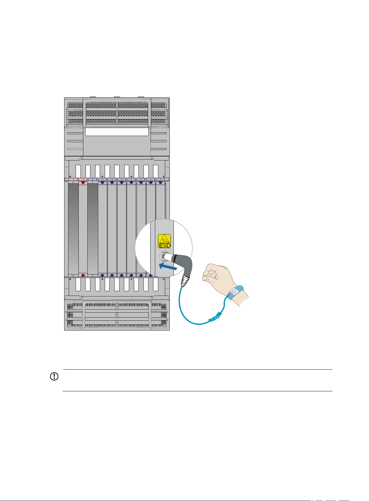
1. Wear the wrist strap on your wrist.
2. Lock the wrist strap tight around your wrist to keep good contact with the skin.
3. Insert the ESD wrist strap into the ESD socket on the switch chassis.
Make sure the ESD wrist strap is correctly grounded.
Figure 1 Attaching an ESD wrist strap to a 12508E
Switch moving
IMPORTANT:
For personal safety, at least four people are required to move a 12518E switch.
When you move an HP 12500E switch, follow these guidelines:
• Remove all the external cables (including the power cords) before moving the chassis.
• For personal safety, have several people to move the switch carefully.
• When moving the switch, hold the handles at both sides of the chassis. Do not hold the plastic panel
of the chassis, the handle of the fan tray, the handle of the back cover of the chassis, or the air vents
2
Page 9

of chassis. Any attempt to carry the switch with these parts might cause equipment damage or even
W
g
p
bodily injury.
Laser safety
ARNING!
Do not stare into any fiber port when the switch has power. The laser li
might hurt your eyes.
Examining the installation site
The HP 12500E Routing Switch Series can only be used indoors. To ensure that th e switch works corre ctly
and to prolong its service lifetime, the installation site must meet the following requirements:
Weight support
Make sure the floor can support the total weight of the rack, chassis, cards, power supplies, and all other
components. Additionally, the floor loading plan must also consider system expansion, such as adding
more cards.
ht emitted from the optical fiber
Temperature
CAUTION:
If condensation appears on the switch when you move it to a high-temperature environment, dry the switch
before powering it on to avoid short circuits.
To ensure the normal operation of the switch, make sure the room temperature meets the requirements
described in Table 1.
Table 1 Temperature r
Tem
erature Range
Operating temperature
Storage temperature –40°C to +70°C (–40°F to +158°F)
Humidity
equirements
• Long term:
0°C to 40°C (32°F to 104°F)
• Short term:
–10°C to +50°C (14°F to 122°F) (no more than 96 hours of
continuous operation in less than 15 days in one year)
• Lasting high relative humidity can cause poor insulation, electricity creepage, mechanical property
change of materials, and metal corrosion.
• Lasting low relative humidity can cause washer contraction and ESD and bring problems including
loose captive screws and circuit failure.
3
Page 10

Maintain appropriate humidity in your equipment room, as described in Table 2.
p
p
p
g
g
Table 2 Humidity requirements
Item S
Operating humidity (noncondensing) 5% to 95%
Storage humidity (noncondensing) 5% to 95%
Operating altitude
Table 3 Operating altitude requirements
Item S
Operating altitude
Cleanness
Dust buildup on the chassis might result in electrostatic adsorption, which causes poor contact of metal
components and contact points, especially when indoor relative humidity is low. In the worst case,
electrostatic adsorption can cause communication failure.
Table 4 Dust concentration limit in the equipment room
ecifications
ecifications
≤ 4000 m (13123.36 ft) (available altitude)
≤ 3000 m (9842.52 ft) (certificated altitude)
EMI
Substance Concentration limit (
Dust particles ≤ 3 x 10⁴ (no visible dust on the tabletop over three days)
NOTE:
Dust particle diameter ≥ 5 μm
articles/m3)
The equipment room must also meet strict limits on salts, acids, and sulfides to eliminate corrosion and
premature aging of components, as shown in Table 5.
Table 5 Harmful gas li
Gas Avera
SO2 0.3 1.0
H2S 0.1 0.5
NO2 0.004 0.15
NH
3
Cl
2
mits in the equipment room
e (mg/m3)Max. (m
1.0 3
0.1 0.3
/m3)
All electromagnetic interference (EMI) sources, from outside or inside of the switch and application
system, adversely affect the switch in a conduction pattern of capacitance coupling, inductance coupling,
4
Page 11

electromagnetic wave radiation, or common impedance (including the grounding system) coupling. To
prevent EMI, take the following actions:
• If AC power is used, use a single-phase three-wire power receptacle with protection earth (PE) to
filter interference from the power grid.
• Keep the switch far away from radio transmitting stations, radar stations, and high-frequency
devices.
• Use electromagnetic shielding, for example, shielded interface cables, when necessary.
• Route interface cables only indoors to prevent signal ports from getting damaged by overvoltage or
overcurrent caused by lightning strikes.
Grounding
Using a good grounding system to protect your switch against lightning shocks, interferences, and ESD
is essential to the operating reliability of your switch.
Make sure the resistance between the chassis and the ground is less than 1 ohm.
Power supply
To meet the power supply requirements:
1. Calculate the system power consumption.
2. Select power modules according to the system power consumption and power supply mode.
3. Verify that the power source on the installation site meets the requirements of the power modules.
For the power consumption and power module specifications of the switch, see "Appendix A Technical
specifications."
Cooling
Plan the installation site for adequate ventilation.
• Leave at least 10 cm (3.94 in) of clearance around the air intake vents and exhaust vents.
• Equip a good cooling system for the cabinet to install the switch.
• Equip a good cooling system for the installation site.
Figure 2, and Figure 3 sho
To ensure normal operation of the switch, make sure the maximum output power of the power
modules is greater than the system power consumption of the switch (reserve certain power for
redundancy). After determining the system power consumption and power supply mode (AC or
DC power supply), you can select power modules as needed.
Make sure the power source of the installation site is steady and can meet the requirements of the
power modules, including the input method and rated input voltage.
w the ventilation of the 12508E, and 12518E.
5
Page 12
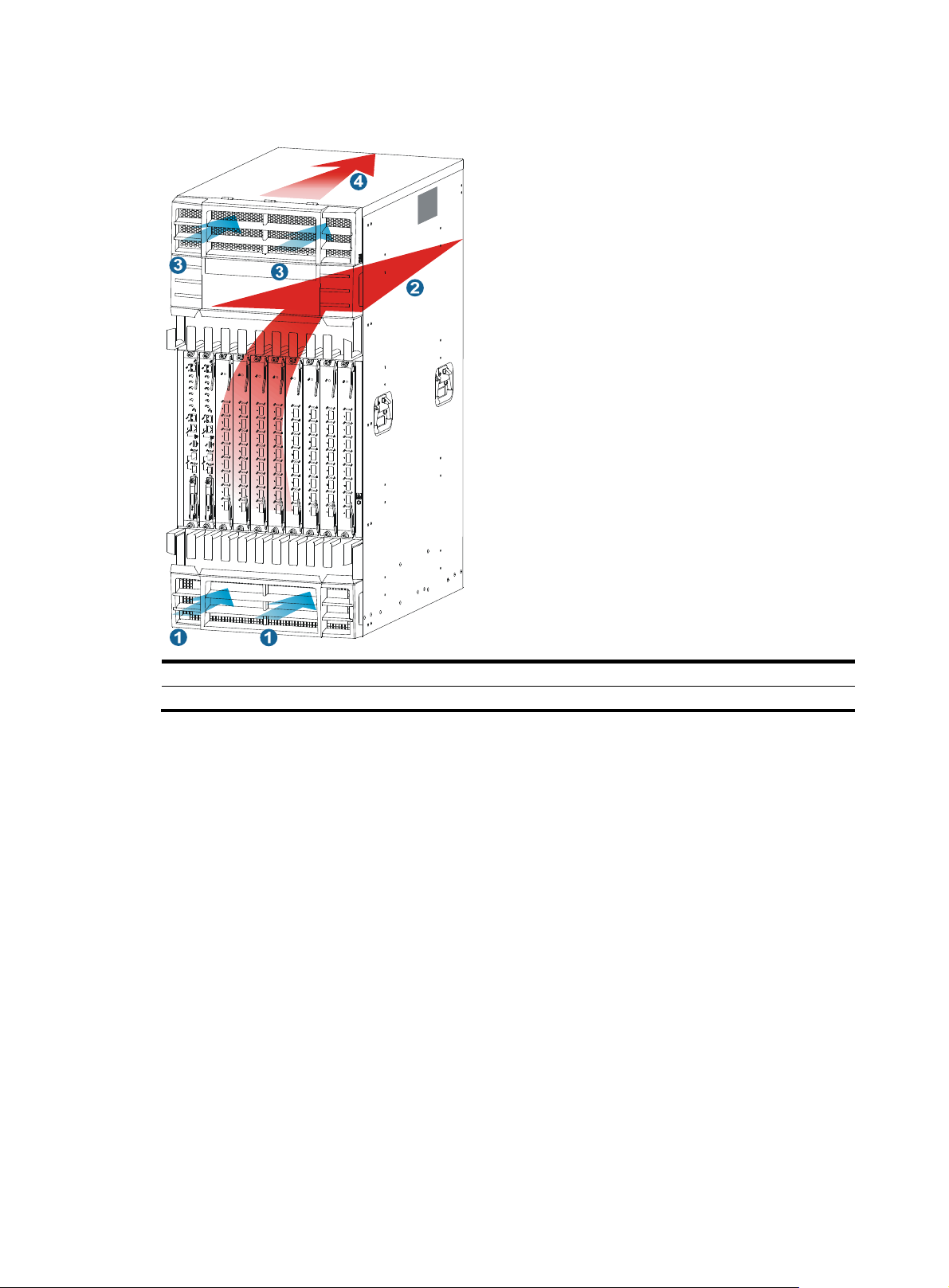
Figure 2 Airflow through a 12508E chassis
(1) Air intake direction of the chassis (2) Air exhaust direction of the chassis
(3) Air intake direction of the power supplies (4) Air exhaust direction of the power supplies
6
Page 13
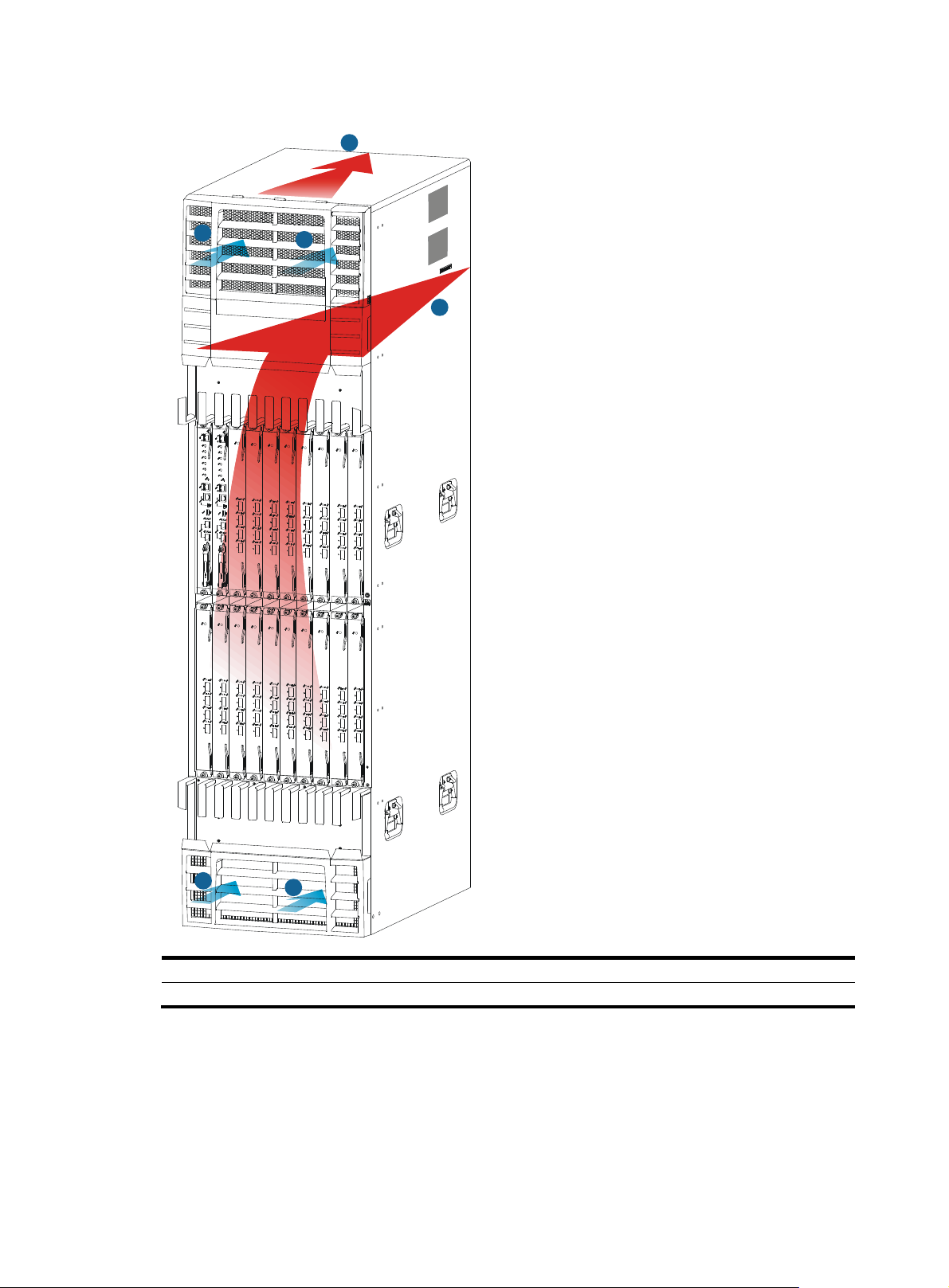
Figure 3 Airflow through a 12518E chassis
4
3
3
2
Space
For easy maintenance, follow these guidelines:
1
1
(1) Air intake direction of the chassis (2) Air exhaust direction of the chassis
(3) Air intake direction of the power supplies (4) Air exhaust direction of the power supplies
7
Page 14

Installation method Space requirements
q
Workbench-mounting
Rack-mounting
IMPORTANT:
• Width of the aisle: ≥ 0.8 m (2.62 ft)
• Clearance between the rack and walls or other devices: ≥ 0.8 m (2.62 ft)
• Clearance between the rack and walls or other devices: ≥ 1.0 m (3.28 ft)
• Equipment room height: ≥ 3 m (9.84 ft)
Follow the rack clearance requirements to make sure the switch does not block the rack doors.
HP recommends that you use a rack with a depth of 1.2 m (3.94 ft) for rack-mounting the switch. For the
chassis space requirements and rack clearance requirements, see Table 6, Figure 5, Figure 6, and Figure
7. F
or more information about switch dimensions, see "Appendix A Chassis views and technical
specifications."
Table 6 Rack mounting space requirements
Model Chassis space requirements
• Height:
{ 12508E: 975 mm (38.39 in)/22 RU
{ 12518E: 1686 mm (66.38 in)/38 RU
• Width: 442 mm (17.40 in)
• Depth:
12508E/12518E AC
{ 859 mm (33.82 in) on switches
installed with cable management
brackets
{ 913 mm (35.94 in) on switches
installed with expansion cable
management brackets
• Height:
{ 12508E: 975 mm (38.39 in)/22 RU
{ 12518E: 1686 mm (66.38 in)/38 RU
• Width: 442 mm (17.40 in)
• Depth:
12508E/12518E DC
{ 759 mm (29.88 in) on switches
installed with cable management
brackets
{ 813 mm (32.01 in) on switches
installed with expansion cable
management brackets
Minimum rack clearance
re
uirements
• Distance between the front rack
post and the inner side of the front
door:
{ 100 mm (3.94 in) on switches
installed with cable
management brackets
{ 154 mm (6.06 in) on switches
installed with expansion cable
management brackets
• Distance between the front rack
post and inner side of the rear door:
769 mm (30.28 in) (Including the
space for cabling power cords.)
• Distance between the front rack
post and the inner side of the front
door:
{ 100 mm (3.94 in) on switches
installed with cable
management brackets
{ 154 mm (6.06 in) on switches
installed with expansion cable
management brackets
• Distance between the front rack
post and inner side of the rear door:
709 mm (27.91 in) (Including the
space for cabling power cords.)
8
Page 15
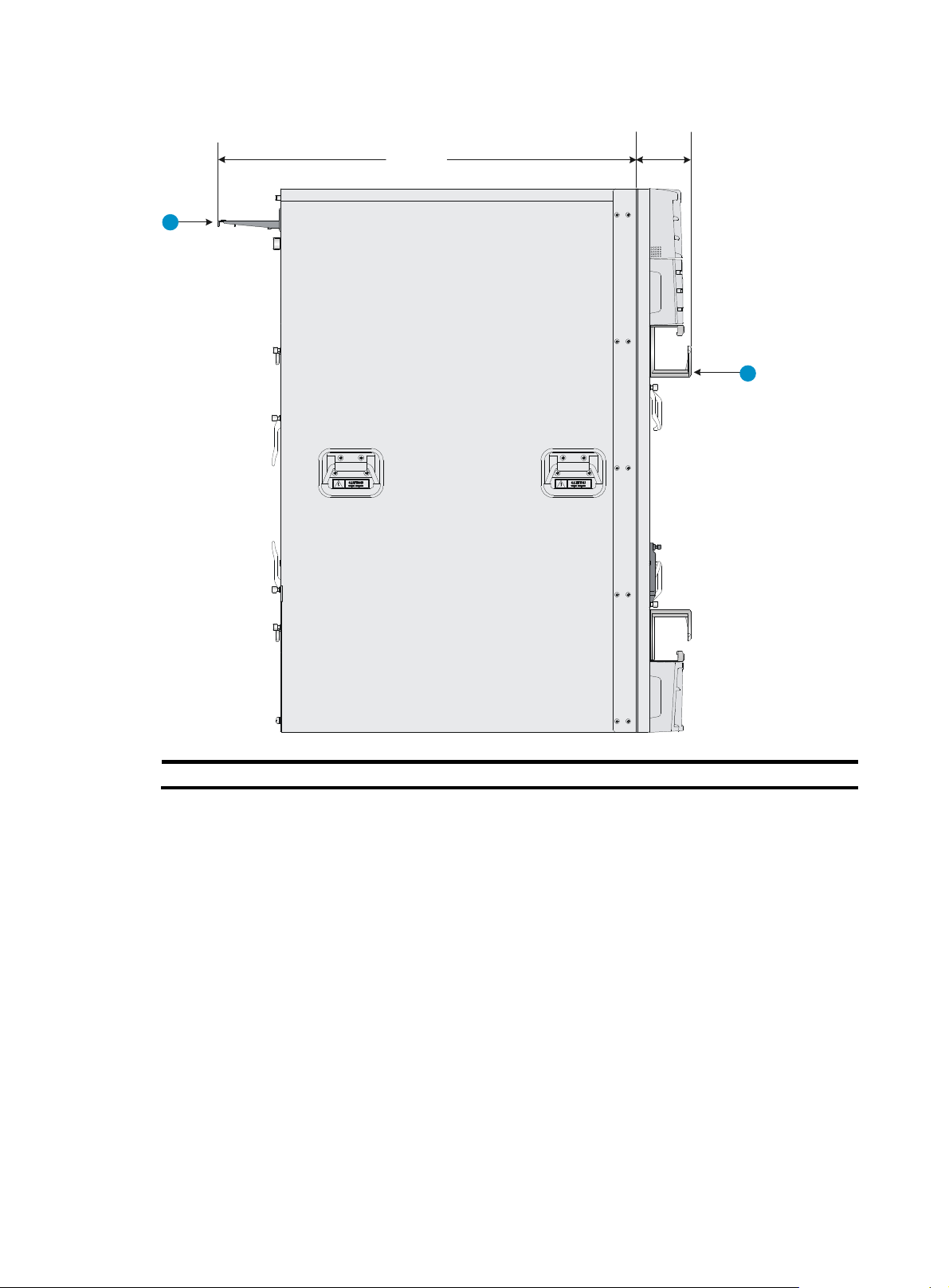
Figure 4 Depth for the 12508E/12518E AC chassis with cable management brackets
759 mm
(29.88 in)
100 mm
(3.94 in)
1
2
(1) Power cabling rack (2) Cable management bracket
9
Page 16
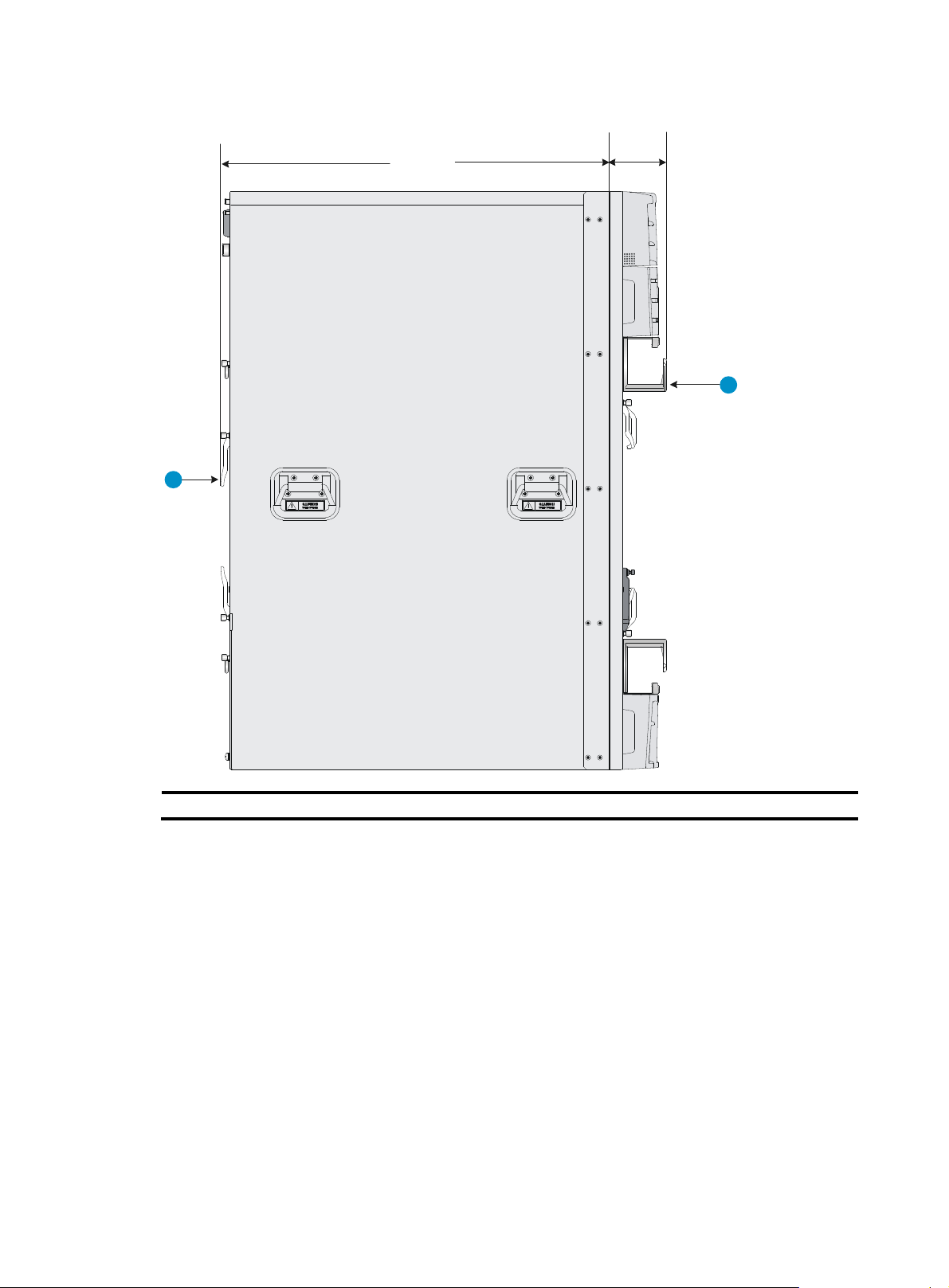
Figure 5 Depth for the 12508E/12518E DC chassis with cable management brackets
659 mm
(25.94 in)
1
100 mm
(3.94 in)
2
(1) Ejector lever on the switching fabric module (2) Cable management bracket
10
Page 17

Figure 6 Depth for the 12508E/12518E AC chassis with expansion cable management brackets
759 mm
(29.88 in)
1
154 mm
(6.06 in)
2
(1) Power cabling rack (2) Expansion cable management bracket
11
Page 18
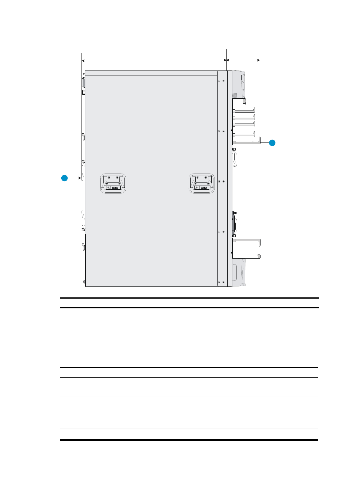
Figure 7 Depth for the 12508E/12518E DC chassis with expansion cable management brackets
y
659 mm
(25.94 in)
1
154 mm
(6.06 in)
2
(1) Ejector lever on the switching fabric module (2) Expansion cable management bracket
Installation tools
You can use the following tools for installation.
Accessories supplied by the switch
Item Quantit
Console cable 1
Grounding cable 1 Grounds the switch.
M6*12 screw 1 set
M6 cage nut 1 set
ESD wrist strap 2 ESD prevention.
Purpose
Connects the console port and the
configuration terminal for switch login.
Secures the switch to the rack.
12
Page 19

Item Quantit
y
g
Purpose
AC/DC power cord
Cable tie Several
NOTE:
The number of screws, nuts, and cable ties supplied with the switch depends on those shipped from the
factory.
User-supplied tools and equipment
• Mechanical lift
• Phillips screwdriver P1 – 100 mm, P2 – 150 mm, and P3 – 250 mm
• Flat screwdriver P4 – 75 mm
• Marker
• Tape
• Diagonal pliers, wire-stripping pliers, and wire clippers
• Socket wrench
Same as the number of power
modules
Transmits the power
Organizes and secures AC power
cords.
Supplied with the 12508E and
12518E switches.
• Cables such as network cables and fiber cables
• Meters and equipment, such as hub and multimeter
• Configuration terminal, such as PC
NOTE:
The rack accessories and installation tools are not included in this section. They mi
the rack model. For more information, see the installation guide of the corresponding rack.
ht vary depending on
13
Page 20
W
g
Installing the switch
ARNING!
To avoid bodily injury, do not touch any wire, terminal, or part marked with a high-volta
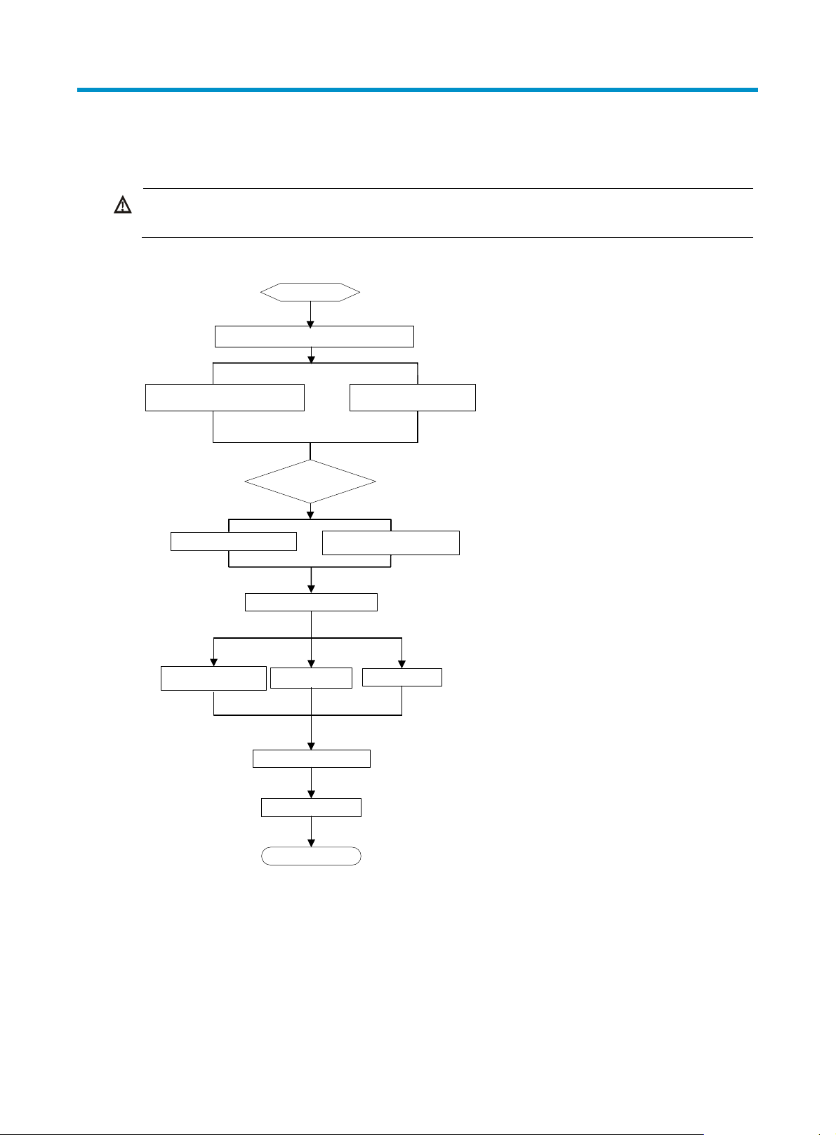
Figure 8 Switch installation procedure
Start
Remove the power frame mounting brackets
e hazard sign.
Install an expansion cable
management bracket (optional)
Determine the
installation method
Install the switch to a rack
Ground the switch
Install a power module
Install a fan tray
Connect the power cord
Install a chassis air filter
(optional)
Mount the switch on a
workbench
Install a card
Verify the installation
End
Confirming installation preparations
Before installing an HP 12500E switch, verify that:
• You have read "Preparing for installation" carefully and the installation site meets all the
requirements.
14
Page 21
• You have all the items listed in the packing list, and the switch was not damaged during shipment.
If anything is damaged or missing, contact the sales agent or customer representative immediately.
For regulatory compliance and safety information, see "Regulatory compliance and safety information."
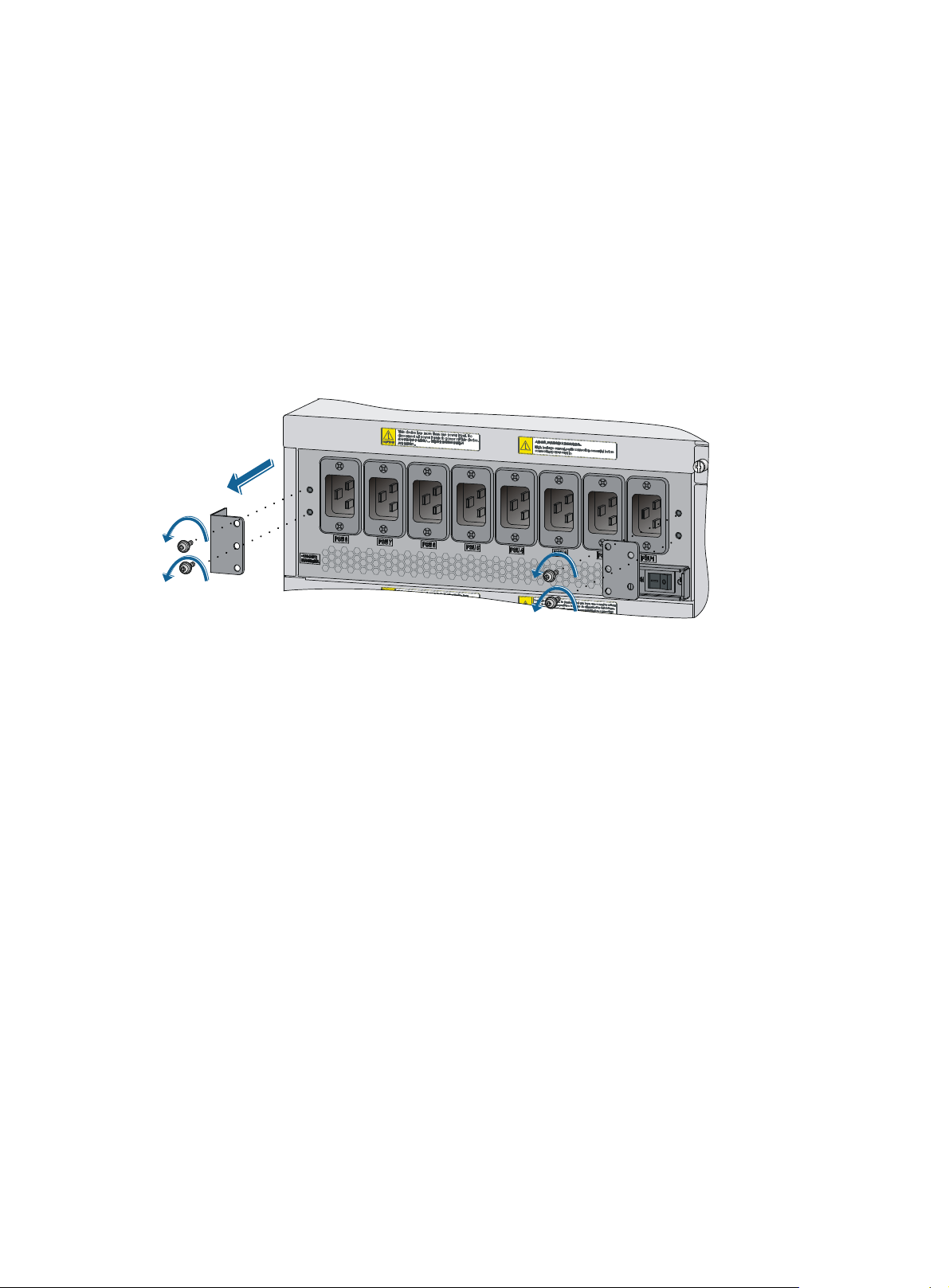
Removing the power frame mounting brackets
The mounting brackets are used to fix the power frame and to protect the frame during transportation. To
ensure smooth installation, remove the mounting brackets from the power frame with a Phillips
screwdriver before you install the switch in the rack. A switch cannot be installed in a rack if the mounting
brackets are not removed.
Figure 9 Removing the power frame mounting brackets
Installing an expansion cable management bracket (optional)
Each 12508E and 12518E switch provides two types of chassis cable management brackets. You can
select either type as needed.
• Cable management brackets—Shipped with the switch. For more information, see " Chassis views
and technical specifications."
• Expansion cable management brackets—Upper cable management bracket with a mark, and
lower cable management bracket with no mark. They are installed in the same positions as the
cable management brackets shipped with the switch except that they can route more cables.
To install expansion cable management brackets, remove the cable management brackets shipped with
the switch first.
Installation preparation
1. Wear an ESD wrist strap and make sure the wrist strap is well grounded.
2. Unpack the expansion cable management brackets.
15
Page 22
IMPORTANT:
• Make sure no filler panel or card is installed on the front panel of the switch before you remove or
install a lower cable management bracket.
• Keep the removed chassis panel and cable management brackets for future use.
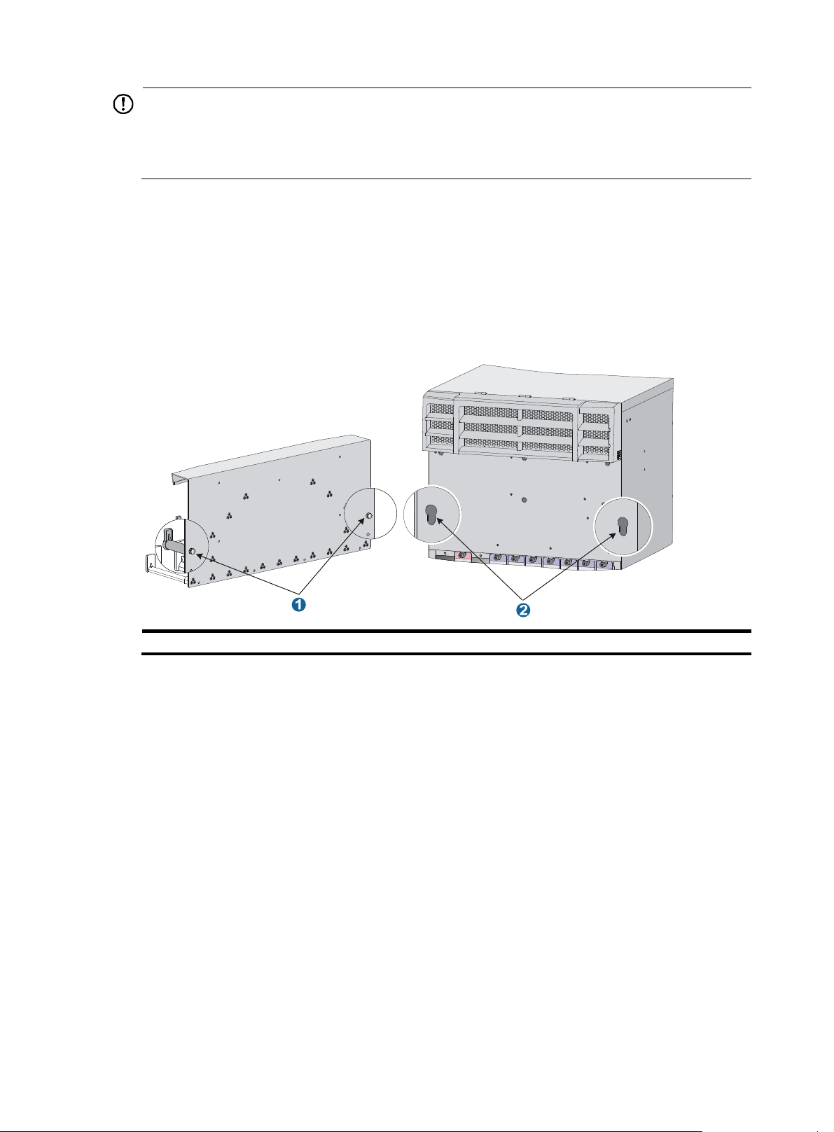
Installation procedure
Each 12500E switch has keyhole standoffs on its cable management bracket and keyholes on the chassis
for securing the cable management bracket to the chassis. See Figure 10.
Figure 10 K
(1) Keyhole standoff (2) Keyhole
eyhole standoff and keyhole
Installing an upper expansion cable management bracket
1. Holding the notches on both sides of the chassis panel above the upper cable management
bracket, gently remove the panel.
2. Pressing the two sides of the front panel, pivot the power frame front panel upward.
3. Loosen the fastening screws on the upper cable management bracket with a Phillips screwdriver.
4. Align the keyhole standoffs on the rear of the cable management bracket with the keyholes on the
chassis and remove the cable management bracket.
5. Align the keyhole standoffs on the upper expansion cable management bracket (with a mark) with
the keyholes on the chassis.
6. Push the expansion cable management bracket forward until it makes close contact with the chassis.
Then pull the expansion cable management bracket downwards a little until the keyhole standoff fits
into the keyhole on the chassis.
7. Unpack the screws come with the expansion cable management bracket and fasten them with a
Phillips screwdriver to secure the expansion cable management bracket to the chassis.
8. Close the power frame front panel.
16
Page 23
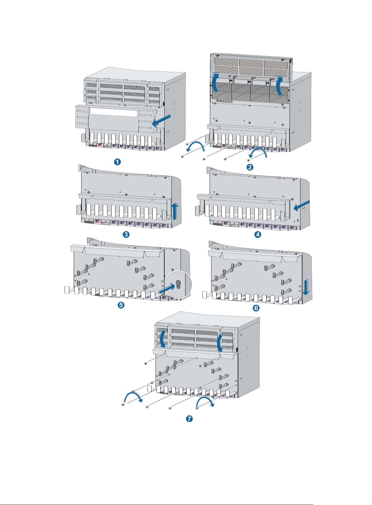
Figure 11 Installing an upper expansion cable management bracket
Installing a lower expansion cable management bracket
1. Remove the filler panel or card on the front panel. For how to remove them, see "Replacement
procedures."
17
Page 24

2. Loosen the fastening screws on the lower cable management bracket with a Phillips screwdriver.
3. Align the keyhole standoffs on the rear of the lower cable management bracket with the keyholes
on the chassis and remove the cable management bracket.
4. Align the keyhole standoffs on the lower expansion cable management bracket (with no mark)
with the keyholes on the chassis.
5. Push the expansion cable management bracket forward until it makes close contact with the chassis.
Then pull the expansion cable management bracket downwards until the keyhole standoff fits into
the keyhole on the chassis.
6. Unpack the screws come with the expansion cable management bracket and fasten them with a
Phillips screwdriver to secure the expansion cable management bracket to the chassis.
7. Install the removed filler panel or card. For more information, see "Installing a card."
For illustration of the installation procedure for a lower cable management bracket, see callouts 2 to 7
in Figure 11.
Installing a chassis air filter (optional)
Chassis air filters are installed at the air intake vents to prevent dust from entering the chassis. Chassis air
filters of the 12500E switches are optional. You can order them as needed.
If you have ordered chassis air filters, HP recommends you to install the air filters before mounting the
switch to the rack.
• 12 50 8 E —The air filter is located at the front of the chassis. For the installation procedures, see
"Installing an air filter on a 12508E."
• 12
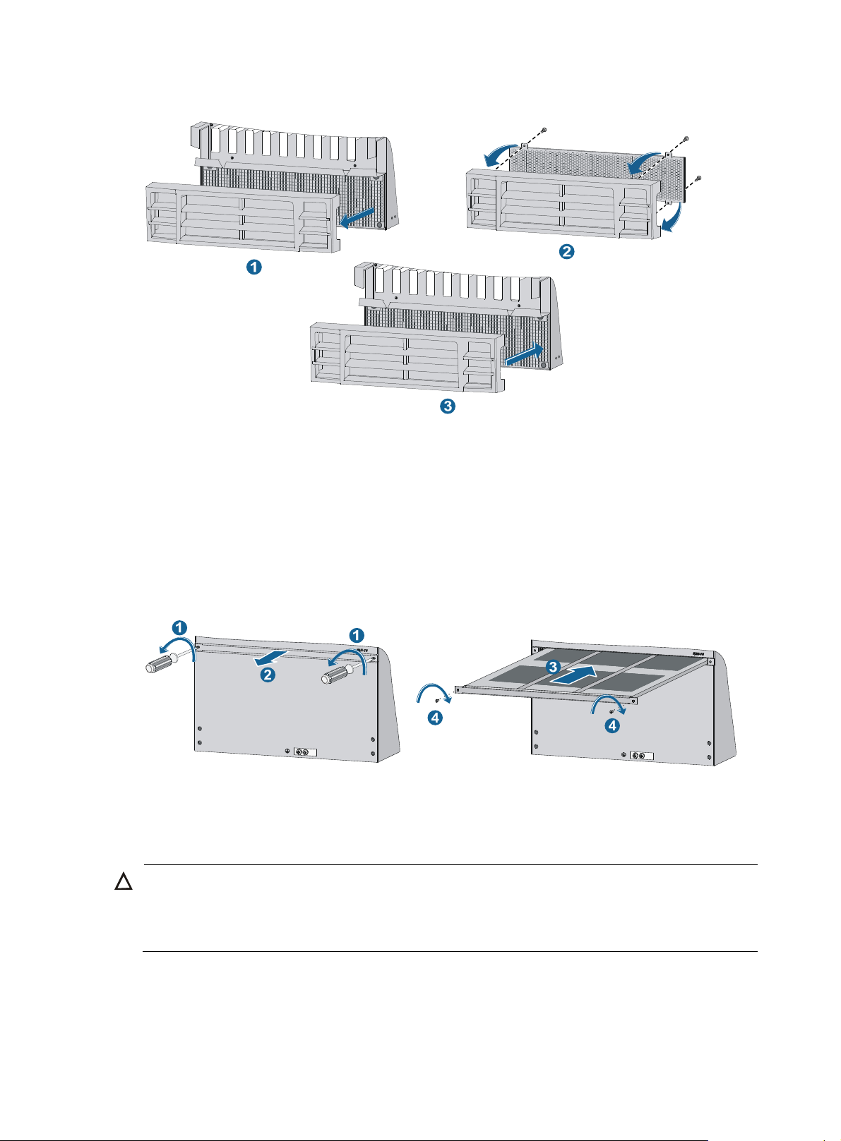
Installing an air filter on a 12508E
1. Hold the notches of the front plastic panel at the bottom part of the chassis, and gently pull the
518 E —The air filter is located at the rear of the chassis. For the installation procedures, see
"Installing an air filter on a 12518E."
plastic panel out.
2. Unpack the air filter, attach it to rear of the plastic panel, align installation holes on the air filter
with the screw holes on the plastic panel, and secure the air filter to the plastic panel with screws.
3. Mount the plastic panel back to the chassis.
18
Page 25
W
A
Figure 12 Installing an air filter
Installing an air filter on a 12518E
1. Use a Phillips screwdriver to loosen the screws at both sides of the plastic panel and remove the
panel.
2. Insert the air filter into the rear of the chassis along the slide rails, and then fasten the screws at both
sides of the air filter.
Figure 13 Installing an air filter
Installing the switch in a rack
CAUTION:
hen moving the switch, hold the handles at both sides of the chassis. Do not hold the plastic panel of the
chassis, the handle of the fan tray, the handle of the back cover of the chassis, or the air vents of chassis.
ny attempt to carry the switch with these parts might cause equipment damage or even bodily injury.
Installation preparation
Confirm the following preparations before starting installation:
19
Page 26

A
• The rack is sturdy and securely grounded.
• There is sufficient clearance of 0.8 m (2.62 ft) around the rack for heat dissipation and installation.
• There is no debris inside or around the rack.
• The total height of the switches to be installed is no higher than the height of the rack and enough
clearance is reserved for cable routing.
• Make sure the clearance above the slide rail is sufficient for the switch and the slide rails can
support the weight of the switch. For the dimensions and weight of the 12500E switch, and the
weight of the hardware components, see "Appendix A Technical specifications."
Installing slide rails and cage nuts to the rack
Before installing the switch in the rack, secure slide rails to the rack. Besides slide rails, you can use a rack
shelf to support the switch. This document describes how to install slide rails only.
To ensure correct installation, use industry-standard slide rails or rack shelves. Slide rails or rack shelves
are not provided with the switch. HP recommends that you order HP slide rail LSTM2KSGD0. The slide
rail can be used in racks where the distance between the front and rear rack posts is in the range of 500
mm to 800 mm (19.69 in to 31.50 in).
Installing slide rails
If the rack has slide rails, skip this section.
The appearance and installation methods of slide rails depend on the slide rail types.
This section uses a 19-inch rack as an example to describe the installation procedures. The rack unit (RU)
(44.45 mm, or 1.75 in) measures the height of rack posts. As shown in Figure 14, eac
h 1 RU has three
mounting holes with center-to-center separations of 15.88 mm (0.63 in), 15.88 mm (0.63 in), and 12.70
mm (0.5 in). When installing the slide rails, make sure the bottom edge of the slide rails aligns with the
middle of the narrowest separation between mounting holes.
To install the slide rails:
1. Mark the position of the slide rail on the rack posts. Make sure the bottom edge of the slide rails
or rack shelf aligns with the middle of the narrower metal area between holes as shown in Figure
14.
TIP:
total of six screws are required within the 2 RU of installation space for each side of the slide rail.
You can mark the position for the top cage nut only.
20
Page 27
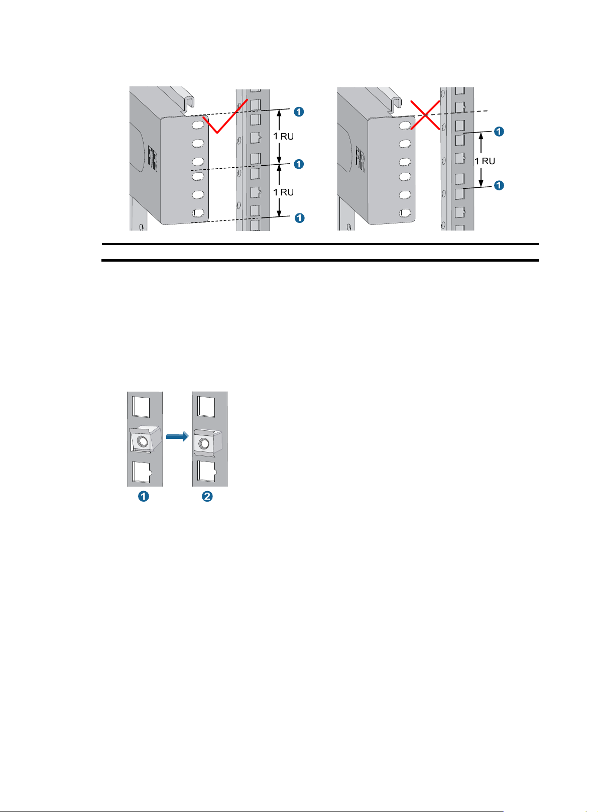
Figure 14 Locating the installation position of the slide rails
(1) Middle of the narrower metal area between holes
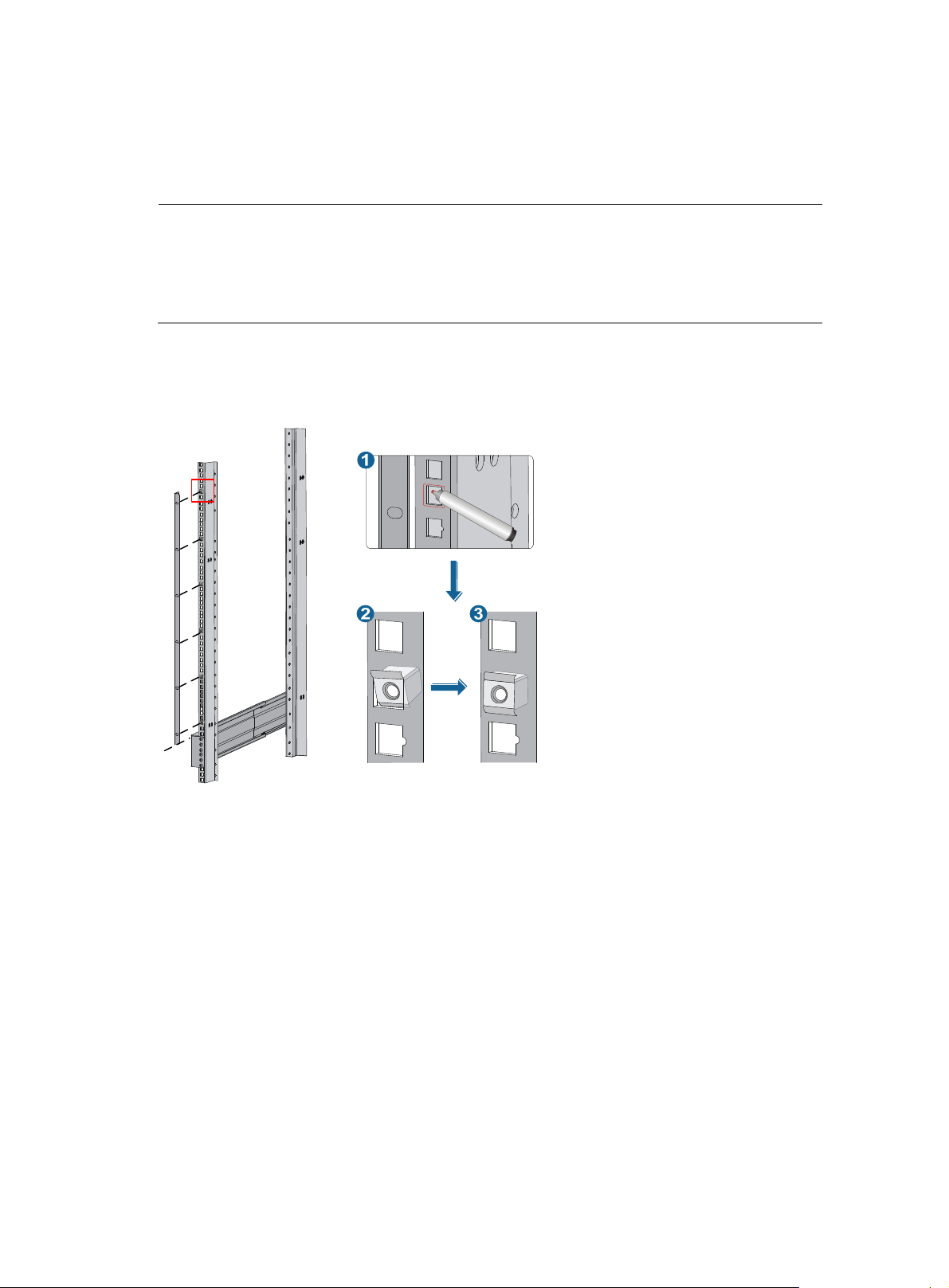
2. Install the cage nuts on the rack posts.
a. Insert the upper ear (callout 1 in Figure 15) of a cage
nut into the corresponding installation
hole.
b. Push the cage nut to lead its lower ear (callout 2 in Figure 15) into th
e same hole.
c. Repeat steps a and b to complete installation of 24 cage nuts on the rack post. (Six cage nuts
for each rack post.
Figure 15 Installing the cage nuts
3. Align the screw holes on the two sides of the right slide rail (marked with F/R) with the marked
holes on the right rack posts, and then fasten the screws.
21
Page 28
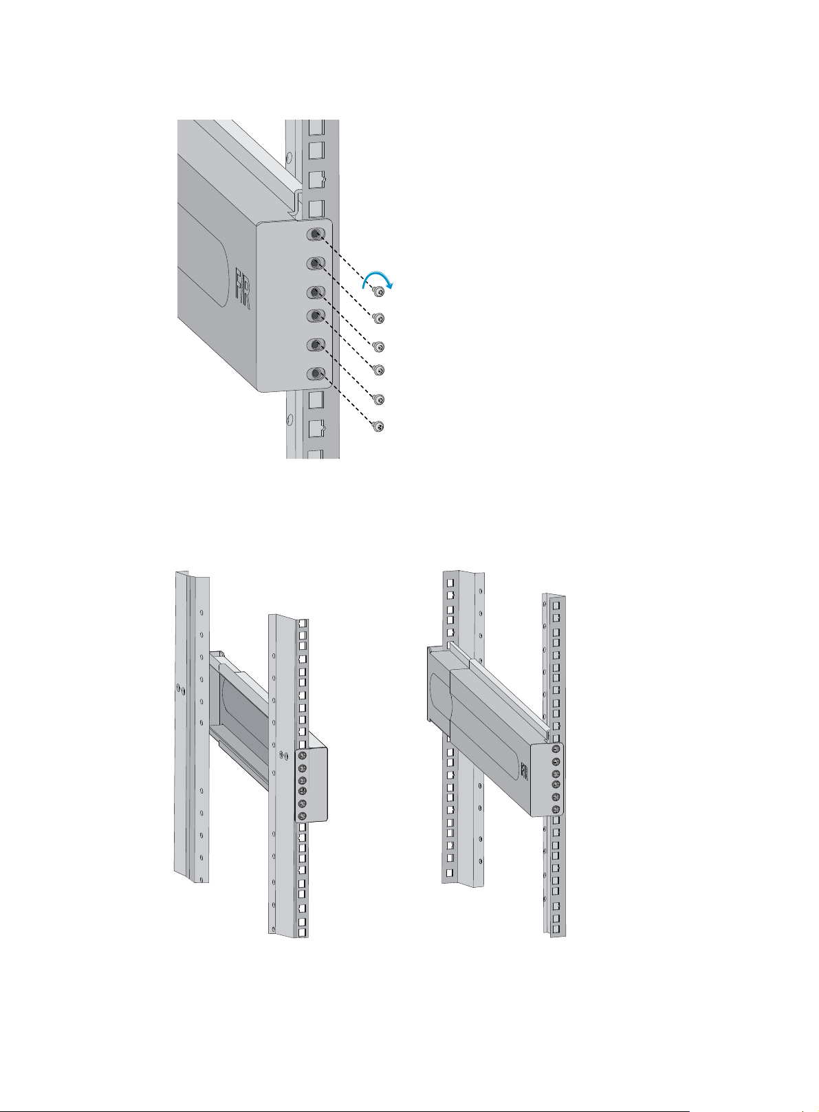
Figure 16 Fastening the screws
4. Use the same method described in step 3 to install the left slide rail to the left rack posts.
Keep the two slide rails at the same height so that the switch can be placed evenly.
Figure 17 Slide rails installed correctly
Installing cage nuts
Before mounting the chassis to the rack, install cage nuts to the front square-holed brackets of the rack.
22
Page 29
g
To install cage nuts to the rack:
1. Align the mounting bracket with the left rack post, making sure its bottom edge and the slide rail
are level. Mark the positions of the cage nuts on the rack post according to the mounting holes on
the mounting bracket. (Each mounting hole on the mounting bracket corresponds to one cage nut.)
NOTE:
The mounting brackets are fixed on the chassis of the 12508E and 12518E before delivery from the
factory. To determine the installation holes for cage nuts, you can remove a mountin
bracket from
the chassis and mark the nut holes, or use a pattern tool to record the installation holes of the
mounting brackets and mark the nut holes accordingly.
2. Install cage nuts to the rack posts using the method described in relevant steps in "Installing slide
rails."
Figure 18 Installing the
cage nuts
Mounting the switch in the rack
Before yo u mount the swi tch in the rack, make sure yo u have ins talled s lide rai ls o r a rack sh elf on the rack
for supporting the switch.
To maximize the stability of the rack, mount the heaviest switch at the bottom of the rack when you install
multiple switches on the rack.
To mount the switch in the rack:
1. Cooperate with several people to place the switch on the slide rails or rack shelf and slide the
switch into the rack until the mounting brackets on the switch touch the front rack posts.
2. Attach the mounting brackets to the rack posts with mounting screws. See Figure 19.
23
Page 30
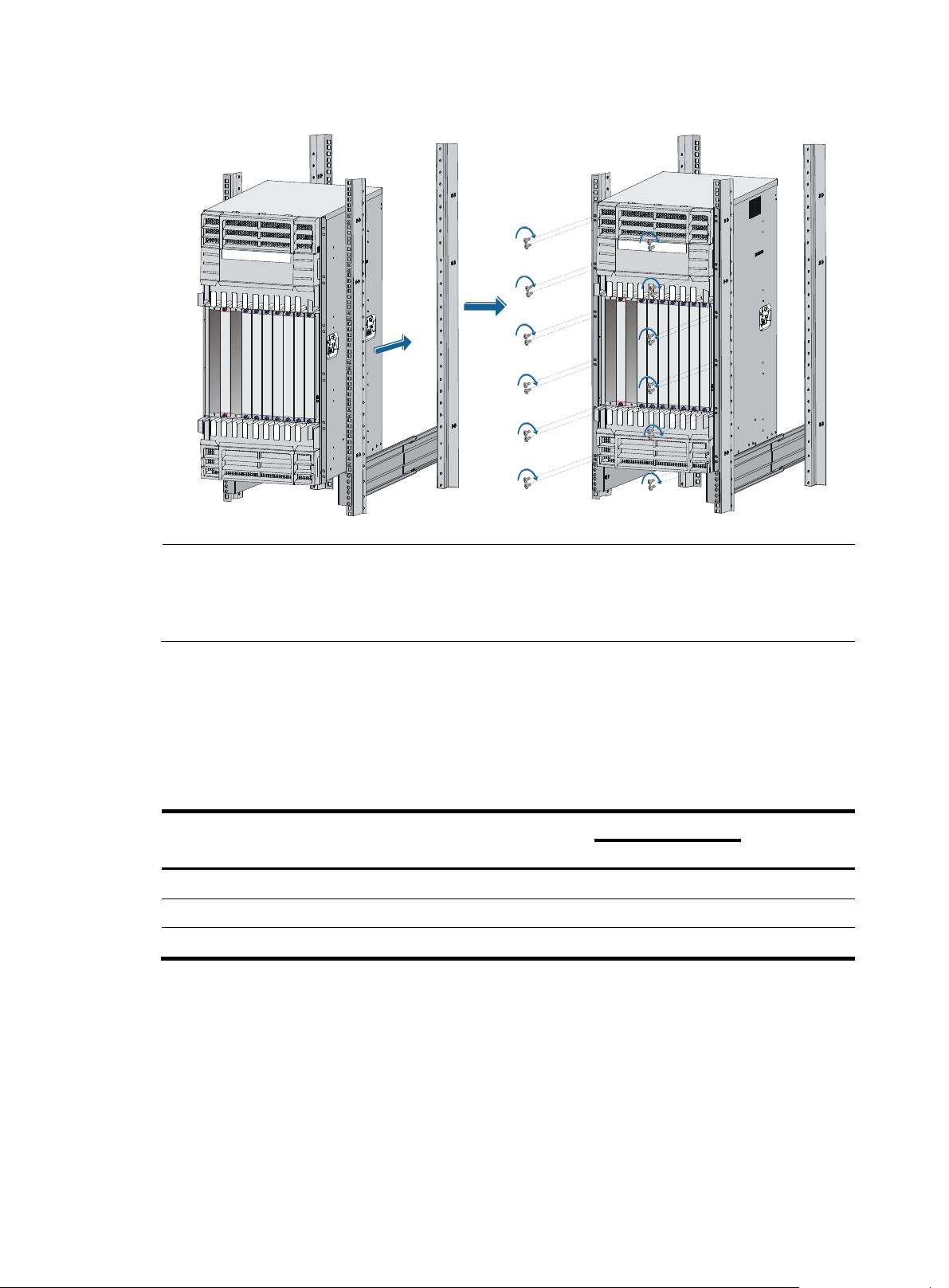
Figure 19 Installing the switch in a standard 19-inch rack (for the 12508E)
NOTE:
If the screw holes on the mounting brackets cannot align with the cage nuts on the rack, verify that the
bottom edge of the slide rail aligns with the middle of the narrowest metal area between mounting holes
and that the cage nuts are installed in the correct holes.
Verifying the installation
After the installation is completed, check the installation against the following checklist. Make sure all
check results are positive.
Table 7 Installation checklist
Result
Item
Yes No
The mounting brackets are firmly attached to the switch.
The switch is sturdy and installed in the right position.
The mounting brackets on the switch are firmly attached to the rack.
Installing the switch on a workbench
Remarks
You can install the switch on a clean, sturdy workbench or on the floor if no rack is available for switch
installation at the site.
24
Page 31

A
A
Installation preparation
Before placing the switch on a workbench or on the floor, confirm the following preparations:
• The workbench or floor is sturdy enough to support the weight of the chassis and its accessories.
• The workbench or floor is correctly grounded.
• The wall anchors are installed.
a. Position the installation holes and drill holes.
Make sure each hole is exact in diameter and depth for the anchor.
b. Assemble each wall anchor by inserting the spade-shaped wedges on the plug into the
grooves on the shank.
c. Put the assembled wall anchors into installation holes and hammer them into the ground.
Figure 20 Installing the wall anchor
(1) Shank (2) Groove
(3) Plug (4) Spade-shaped wedge
Installation procedures
IMPORTANT:
llow 0.8 m (2.62 ft) of clearance around the switch for heat dissipation.
To install the switch:
1. Hold the two sides of the switch and steadily move the switch to the workbench.
2. Lift the switch a little higher than the workbench and put it on the workbench.
3. (Optional.) Install the cable management brackets on both sides of the switch and fasten the
screws, as shown in Figure 21.
NOTE:
The circled areas in Figure 21 are the cable management bracket installation holes.
12508E or 12518E switch has one column of installation holes.
25
Page 32

Figure 21 Installing cable management brackets on both sides of the switch
1
2
(1) Installation holes (2) Cable management brackets
4. Secure the L-shaped bracket to the switch.
5. Move the switch to make sure holes in the L-shaped bracket align with wall anchor holes in the
ground.
6. Insert the anchor bolts in the holes, and use a wrench to fasten the bolts.
26
Page 33

W
g
g
g
Figure 22 Installing L-shaped brackets
(1) Anchor bolt (2) L-shaped bracket
Grounding the switch
ARNING!
For the safety of operators and equipment, securely
between the switch chassis and the ground is less than 1 ohm.
Most racks are equipped with a grounding strip. You can connect the yellow-green grounding cable of
the switch to the grounding strip.
CAUTION:
Connect the grounding cable to the earthin
or lightning rod.
Use the supplied grounding cable (CAT 6 cable with dual-hole ring terminals).
To connect the grounding cable:
1. Remove the two grounding screws from the switch chassis.
2. Use the grounding screws to attach one end of the grounding cable to the chassis.
round the switch. Make sure the resistance readin
system in the equipment room. Do not connect it to a fire main
3. Connect the other end of the grounding cable to the grounding strip of the rack in the same way.
27
Page 34

g
Figure 23 Connecting the grounding cable for the 12508E
If there is no grounding point on the rack, you can attach the grounding cable to a grounding strip. The
installation procedures are similar.
Installing a power supply
The 12500E switches supports both AC and DC power supply. You can select either AC or DC power
supplies as needed. For how to connect power cords, see "Connecting power cords."
Installation preparation
CAUTION:
• Hold power module by the bottom when moving it. Never attempt to lift a power module with its handle
because the handle is not desi
to the module.
• When inserting or removing a power module, verify that the switch is sturdy. To prevent bodily injury,
avoid tipping the switch chassis.
• When hot-plugging power modules, make sure the insertion interval is no less than 30 seconds.
ned to support weight. Doing so might result in bodily injury or damage
To prepare for installation:
1. Wear an ESD wrist strap and make sure it is correctly grounded.
2. Remove the blank panel (if any) from the slot to be used.
28
Page 35

Installing an AC power supply
Installing an AC power module
IMPORTANT:
• Make sure the number of power modules is sufficient for the switch to operate correctly.
• Each receptacle on the rear of the power frame corresponds to a power module slot. To enable an AC
power module to operate correctly, provide power supply to the relevant receptacle.
• Distribute power modules in the upper and lower frames evenly on the 12508E.
1. Rotate the power frame panel out with both hands to open the panel.
2. Pull the clip at the bottom left corner of the power module to the left to open the power module
cover.
3. Insert the power module slowly into the slot until it fits in completely.
4. Close the power module cover and press the clip at the bottom left corner of the power module.
5. Push in the power module cover to ensure secure installation of the power module.
Figure 24 Installing a power module for the 12508E
6. Repeat steps 1 to 5 to install other power modules and then close the power frame panel.
29
Page 36

Figure 25 Closing the power frame panel for the 12508E
Installing a DC power supply
The procedure for installing a DC power module is similar to installing an AC power module. For more
information, see "Installing an AC power module."
Installing a fan tray
CAUTION:
• The fan trays are heavy. Do not try to move a fan tray by yourself.
• Hold a fan tray by the bottom when moving it. Never attempt to lift a fan tray with its handle because the
handle is not designed to support weight. Doing so might result in bodily injury or damage to the
module.
Each of the 12508E and the 12518E has two fan trays. They are installed in the same way.
To install a fan tray:
1. Wear an ESD wrist strap and make sure it is correctly grounded.
2. Unpack the fan tray.
3. Remove the blank panel from the slot to be used.
Figure 26 Removing the blank panel from the fan tray slot of the 12508E
30
Page 37

4. Lift the fan tray and push it into the slot until it is firmly seated in the slot.
5. Fasten the captive screws on the front panel of the fan tray.
Figure 27 Installing a fan tray
Installing a card
On a 12508E or 12518E, install at least one MPU, one LPU, and seven switching fabric modules.
The 12500E does not support intermixing of the MPU, LPU, and switching fabric modules.
Use one of the following positions to install the card:
• Install MPUs, Ethernet interface cards, and OAA cards at the front of the switch chassis. Slot 0 and
Slot 1 are for MPUs and other slots (slots 2 to 9 for the 12508E, and slots 2 to 19 for the 12508E)
are for Ethernet interface cards and OAA cards.
• Install switching fabric modules in the switching fabric module slots (slots 10 to 18 for the 12518E,
and slots 20 to 28 for the 12518E) at the rear of the chassis.
You can install MPUs, LPUs, and switching fabric modules in a similar way. This section describes how to
install an MPU as an example.
Installation preparation
1. Wear an ESD wrist strap and make sure it is correctly grounded.
2. Remove the blank panel (if any) from the slot to be used.
3. Unpack the card to be installed.
31
Page 38

NOTE:
• Keep the removed the blank panel and protection cover for future use.
• All the cards for the 12500E are hot-swappable.
Installation procedure
IMPORTANT:
• Fasten the screws of each card right after you insert it.
• To avoid damage to a card, do not use excessive force when installing and removing the card.
• You can remove a protective cover of any model by using the same way illustrated in this document.
To install a card:
1. Remove the protection cover before installing an MPU or an LPU. Skip this step if the card does not
have a protection cover:
a. Wear an ESD wrist strap and then loosen the captive screws that attach the MPU or the LPU to
the protection cover with a Philips screwdriver.
b. Pull the MPU or the LPU out of the protection cover gently.
Figure 28 Removing the protection cover
2. Move the ejector levers on the front panel of the MPU outwards, hold up the MPU by one hand
without touching any electronic components on the MPU, and hold the front panel by the other
hand to push the MPU into the slot along the slide rails slowly.
32
Page 39

3. Push the ejector levers inward to ensure close contact between the MPU and the backplane.
4. Position the screws into the holes and fasten them with a screwdriver to attach the MPU.
Figure 29 Installing an MPU
1
3
2
4
Connecting power cords
Follow these guidelines before connecting power cords:
• For lightning protection, the AC power should be led through an external lightning device into a
12500E switch. For more information, see "Appendix D Lightning protection."
• Make sure the power switch on the power frame is in the OFF position.
• For personal and switch safety, do not connect the power cords with the power. Power off the
grounding strip, connect the power cords, power on the grounding strip, and then power on the
switch.
Connecting an AC power cord
Each Power receptacle corresponds to a power module slot. For example, if slot 1 is installed with a
power module, the number 1 Power receptacle must be connected to a power source with an AC power
cord to make the power module operate correctly.
The AC power system for the 12500E requires 16A AC power cords. You need to prepare 16A power
strips, and make sure the AC power supply system can provide enough power. For AC power cords used
in different countries or regions, see "Appendix A Technical specifications."
The 12508E-AC and 12518E-AC models adopt the PSE20KA1 AC power system.
33
Page 40

A
To connect the PSE20KA1 AC power cords:
1. Secure the power cabling rack to the power frame using screws with spring washers and flat
washers.
Figure 30 Installing the power cabling rack
2. Insert the connector of an AC power cord into the power receptacle.
3. Secure the AC power cord to the cabling rack with cable ties.
4. Repeat steps 2 and 3 to organize and secure other AC power cords.
5. Connect the other end of the AC power cords to the power source.
Figure 31 Connecting AC power cords
16A
4
5
3
2
1
Connecting a DC power cord
CAUTION:
plastic protection cover is installed in front of the terminal block to protect operators from being shocked.
Remove the protection cover before connecting power cords and then install the protection cover
promptly.
34
Page 41

Eight pairs of wiring terminals (marked PSU1 through PSU8) are available on the DC terminal block of
the 12508E/12518E. The wiring terminals correspond to the power modules. The power source provides
power to the switch through the wiring terminals. If slot 1 is installed with a power module, the wiring
terminals marked PSR1 or PSU1 must be connected to the power source with a DC power cord to make
the power module operate correctly.
The 12508E-DC and 12518E-DC models adopt the PSE20KD1 DC power system.
To connect the PSE20KD1 DC power cords:
1. Remove the screws from the power frame.
2. Secure the blue DC power cord to the NEG (–) terminal on the terminal block with screws using a
Phillips screwdriver.
3. Secure the ring terminal of the black power cord to the RTN (+) terminal on the terminal block with
screws using a Phillips screwdriver.
Figure 32 Connecting the DC power cords to terminals on the power supply
4. Connect the other end of the DC power cord to the power source:
{ Connect the other end of the black DC power cord to the RTN (+) terminal that provides power
to the switch.
{ Connect the other end of the blue DC power cord to the –48V terminal that provides a power
supply to the switch.
5. Install the protection cover:
a. Remove the screws on the DC power frame.
b. Install the protection cover on the wiring terminals.
c. Fasten the screws using a Phillips screwdriver.
35
Page 42

W
A
Figure 33 Installing the protection cover
2
1
1
Verifying the installation
ARNING!
12508E has one power switch, and a 12518E has two power switches. Make sure you have turned off
the power before checking the installation to avoid bodily injury and switch damage.
After the installation is completed, verify the installation against the following list. Be sure that all check
results are positive.
Table 8 Installation checklist
Item
3
2
4
4
Result
Remarks
Yes No
The grounding cable is correctly grounded.
Fan trays are correctly installed and make close contact
with the backplane.
Power modules are correctly installed and have close
contact with the frames.
The power switch is off (the power switch is at the OFF
position).
Power cords are correctly connected.
MPUs are correctly installed and have close contact with
the backplane.
LPUs are correctly installed and have close contact with
the backplane.
Switching fabric modules are correctly installed and have
close contact with the backplane.
36
Page 43

Connecting the switch to the network
Cable routing recommendations
Interface cables and power cords should be separately routed. Reasonable cable routing can improve
efficiency by facilitating installation and removal of fan trays and some other components. Follow these
guidelines when you route the cables:
• Interface cables of a 12508E and 12518E are routed through the upper and lower cable
management brackets on the chassis and bound at cabling racks on chassis sides, depending on
the available equipment room condition.
• Put all the data signal cable adapters neatly under the chassis (instead of any places outside the
chassis in case of unexpected damages).
• The power cords run along the left-rear of the chassis and out of the chassis either from the chassis
top or the raised floor depending on the equipment room conditions (power distribution rack,
lightning protection box, and connector strip, etc.) of the exchange office.
• Attach cables as near the switch as possible. The cables between the fixing point and switch
interfaces must be bound loosely.
• Long cables can be bound with cable ties. Do not bind cables at the air exhaust vent to prevent the
cables from aging too fast. For more information, see "Appendix E Cable management."
• To identify cables, you can stick labels on them. For more information, see "Appendix F
Engineering labels for cables."
Logging in to the switch
Co nsole port log in or USB console port l ogin, which is most co mmonly used, i s the only method for initial
login to the switch. It is the prerequisite to configuring other login methods.
Connecting the console cable
Before login through the console port or USB console port, connect the PC (or terminal) and the switch
using the following methods accordingly:
• Console port—Use the console cable to connect the serial port on the PC (or terminal) to the console
port on the switch.
• USB console port—Use the console cable to connect the USB port on the PC (or terminal) to the USB
console port on the switch.
Introduction to console cables
• Console cables connecting the console port on a switch and serial port on a PC or terminal
The console cable is an 8-core shielded cable, with a crimped RJ-45 connector for connecting to
the console port of the switch, and a DB-9 female connector for connecting to the serial port on the
console terminal.
Figure 34 shows the console c
able and Table 9 shows its pinouts.
37
Page 44

p
p
Figure 34 Console cable connecting the serial port and the console port
Table 9 Pinouts for the console cable connecting the serial port and the console port
RJ-45
1 RTS 8 CTS
2 DTR 6 DSR
3 TXD 2 RXD
4 CD 5 SG
5 GND 5 SG
6 RXD 3 TXD
7 DSR 4 DTR
8 CTS 7 RTS
in Signal DB-9
in Signal
• Console cables connecting the USB console port on a switch and the USB port on a PC or terminal
The console cable consists of one mini-USB A/B connector for connecting to the USB console port
on the switch and one USB A connector for connecting to the USB port on the PC or terminal.
Figure 35 shows the console c
able and Table 10 shows its pinouts.
Figure 35 Console cable connecting the USB port and the USB console port
Table 10 Pinouts for the console cable connecting the USB port and the USB console port
USB A pin
1 VBUS 1 VBUS
2 D- 2 D-
3 D+ 3 D+
4 ID(NC)
4 GND 5 GND
Signal mini-USB A/B pin Signal
38
Page 45

Connection procedure
Figure 36 Connecting through the console port and the serial port
To connect the console cable through the console port:
1. Connect the DB-9 connector of the console cable to the serial port on a PC or terminal.
2. Connect the RJ-45 connector of the console cable to the console port on the MPU of the switch.
To connect the console cable through the USB console port:
3. Connect the USB-A connector of the console cable to the USB port on a PC or terminal.
4. Connect the mini-USB A/B connector of the console cable to the USB console port on the MPU of
the switch.
NOTE:
• If two MPUs are installed on the switch, log in through the console port or USB console port on the active
MPU (typically with a smaller slot number) for the first login.
• When you remove the console cable, first disconnect the switch end, and then disconnect the PC end.
39
Page 46

Setting up a configuration environment
If you use the Windows 2003 Server operating system on your PC, add a HyperTerminal, and then log
in to and manage the switch as described in this document. If you use Windows 2008 Server, Windows
7, Windows Vista, or any other operating system on your PC, use the third party terminal software. For
how to use the third party terminal software, see the user guide or online help of that software.
Windows 2000 and Windows XP operating systems have the HyperTerminal. This section takes
Windows XP as an example.
To set up a configuration environment:
1. Select Start > All Programs > Accessories > Communications > HyperTerminal.
The Connection Description dialog box appears.
2. Enter the name of the new connection in the Name field and click OK.
Figure 37 Connection description
3. Select the serial port to be used from the Connect using list, and click OK.
40
Page 47

Figure 38 Setting the serial port used by the HyperTerminal connection
4. Set Bits per second to 9600, Data bits to 8, Parity to None, Stop bits to 1, and Flow control to None,
and click OK.
Figure 39 Setting the serial port parameters
5. Select File > Properties in the HyperTerminal window.
41
Page 48

Figure 40 HyperTerminal window
6. On the Settings tab, set the emulation to VT100 and click OK.
NOTE:
HP recommends that you select the Windows keys option.
Figure 41 Setting the terminal emulation in Test Properties dialog box
42
Page 49

t
Powering on the switch
IMPORTANT:
Before powering on the switch, identify the power switch in the equipment room so that you can disconnec
the power module promptly in case of an emergency.
Before powering on the switch, verify that:
• The interface cables, power cords, and the grounding cable are correctly connected.
• The input power voltage meets the requirement of the switch.
• The console cable is correctly connected, the terminal or PC used for configuration has started, and
the configuration parameters have been set.
Powering on the switch
1. Turn on the power switch of the power source.
2. Turn on the power switch on the switch.
After the switch is powered on, the basic manufacturing information about the switch is displayed:
DDR2 SDRAM test successful.
System is starting...
Booting Normal Extend BootWare
The Extend BootWare is self-decompressing
Done!
****************************************************************************
* *
* HP 12500 BootWare, Version 2.20 *
* *
****************************************************************************
Copyright (c) 2010-2013 Hewlett-Packard Development Company, L.P.
Compiled Date : Sep 4 2013
CPU Type : P5040
CPU L1 Cache : 32KB
CPU L2 Cache : 1024KB
CPU Clock Speed : 1800MHz
Memory Type : DDR3 SDRAM
Memory Size : 8192MB
Memory Speed : 1200MHz
BootWare Size : 8MB
Flash Size : 512MB
cfa0 Size : 4002MB
NVRAM Size : 1024KB
BASIC CPLD Version : 001
EXTENDED CPLD Version : 001
PCB Version : Ver.A
The switch initiates the power-on self-test (POST) and the results are displayed at the console
terminal.
43
Page 50

Board self testing...........................
Board steady testing... [ PASS ]
Board SlotNo... [ 1 ]
Subcard exist testing... [ PASS ]
DX246 testing... [ PASS ]
PHY88E1111 testing... [ PASS ]
CPLD1 testing... [ PASS ]
CPLD2 testing... [ PASS ]
NS16550 register testing... [ PASS ]
The default switch's Mac address... [00:0F:11:11:10:00]
CF Card testing... [ PASS ]
BootWare Validating...
Press Ctrl+B to enter extended boot menu...
When the POST is completed, the switch boots the applications. The following information
appears on the terminal screen (only part of the display information is given in this example):
Starting to get the main application file--flash:/switch.bin!
The main application file is self-decompressing.............................
..........................................................................
..........................................................................
..........................................................................
..........................................................................
..........................................................................
..........................................................................
Done!
System is starting...
Starting application at 0x00100000 ...
TLB init OK.
LBC init OK.
LAW init OK.
Bsp init start...
MMU init OK.
CRC init OK.
Frame data init OK.
Connect IRQ 0 OK.
Enable IRQ 0 OK.
Connect IRQ 1 OK.
Enable IRQ 1 OK.
Connect IRQ 2 OK.
Enable IRQ 2 OK.
Connect IRQ 4 OK.
Enable IRQ 4 OK.
Connect IRQ 5 OK.
Enable IRQ 5 OK.
Connect IRQ 6 OK.
3. After the switch completes booting the applications, the following information appears on the
terminal screen:
Press ENTER to get started.
4. Press Enter to begin configuring the switch at the prompt:
44
Page 51

t
A
<Sysname>
NOTE:
• The 12500E routing switches provide a command line interface (CLI). For more information abou
the CLI, see
Guide.
HP FlexFabric 12500 and 12500E Routing Switch Series Fundamentals Configuration
• The output depends on your switch model.
Verification after power-on
HP recommends that you check the following conditions after the switch is powered on:
• The cooling system is operating. You should be able to hear fan rotation noise and feel air being
blown out.
• All the system LEDs on the MPUs are functioning correctly.
Table 11 LED status when the 12508E/12518E operates correctly
Module LED Status
SFC (red and green) Flashing green
LC (red and green) Flashing green
MPU
LPU RUN (red and green) Flashing green
Switching fabric module RUN (red and green) Flashing green
Power monitoring
module
Fan
FAN (red and green) Flashing green
PWR (red and green) Flashing green
ACT (green) Steady on
RUN (red and green) Flashing green
RUN (green) Flashing
ALM (red) Off
RUN (green) Flashing
ALM (red) Off
Connecting the switch to the network
TIP:
fter connecting the switch to the network, you can use the ping or tracert command to check the
interoperability between the switch and network. For more information, see
12500E Routing Switch Series Network Management and Monitoring Configuration Guide
45
HP FlexFabric 12500 and
.
Page 52

Connecting the switch to the network through the AUX port
You need an AUX cable when configuring a switch with the remote modem dial-up approach.
Introduction
An AUX cable is an 8-core shielded cable. At one end of the cable is an RJ-45 connector and at the other
end is a DB-9 (male) connector. Plug the RJ-45 connector into the AUX port of the switch and the DB-9
(male) connector into the DB-9 (female) port of the modem. An AUX cable is the same as a console cable.
For more information, see Figure 34 and Table 9.
Connection procedure
To connect the AUX port:
1. Plug the RJ-45 connector of the AUX cable into the AUX port of the switch.
2. Plug the DB-9 (male) connector at the other end into the serial port of the modem.
Connecting the switch to the network through a copper Ethernet port
The 10/100/1000Base-T copper ports of the switch support MDI/MDI-X auto-sensing. They are
connected to the network through category-5 or above twisted pairs that are equipped with RJ-45
connectors.
NOTE:
No Ethernet twisted pair cables are shipped with the switch. Prepare them by yourself.
Connection procedure
To co nn ec t a 10/ 100 /10 00 Ba se -T po r t:
1. Plug one end of an Ethernet twisted pair cable into the copper Ethernet port (RJ-45 port) to be
connected on the switch.
2. Plug the other end of the cable into the RJ-45 port of the peer device.
Connecting the switch to the network through a fiber Ethernet port
Use an optical fiber to connect an XFP, SFP, CFP, SFP+, or QSFP+ port on the switch to the network. You
must install a transceiver module to the switch, and then insert the fiber connector to the module.
Introduction to fiber connector
Fiber connectors are indispensable passive components in an optical fiber communication system. They
allow the removable connection between optical channels, which makes the optical system debugging
and maintenance more convenient and the transit dispatching of the system more flexible. Among
various fiber connectors, only the LC connector is described here.
46
Page 53

Figure 42 LC connector
Precautions
Follow these precautionary steps:
• When selecting a fiber network facility, make sure the type of the connector and the fiber matches
the adopted fiber port.
• Be sure to install the dust cover if the fiber port is not connected to a fiber connector.
• Some invisible rays might be emitted from the fiber port if the fiber port is not connected to a fiber
connector or the dust cover is removed. Therefore, never stare at the fiber port directly.
• Never bend or curve a fiber when connecting it.
Installing the XFP, SFP, SFP+, and QSFP+ modules
CAUTION:
Do not touch the golden finger of a transceiver module during installation.
The installation of the XFP, SFP, SFP+, and QSFP+ modules is similar. This section uses an SFP+ module
as an example.
To install an SFP+ module:
1. Remove the optical fiber if the SPF+ module is installed with an optical fiber.
2. Put on an ESD wrist strap, and make sure it has close skin contact, and is correctly grounded.
3. Unpack the SFP+ module and make sure the clasp is closed.
4. Gently insert the SFP+ module into the port until it fits in completely, as shown in Figure 43.
Figure 43 Installing an SFP+ module
IMPORTANT:
Do not remove the dust plug of the SFP+ module port before installing an optical fiber.
47
Page 54

g
Installing the CFP module
1. Put on an ESD wrist strap. Make sure it has close skin contact and is correctly grounded.
2. Unpack the CFP module.
3. Insert the CFP module gently into the port until it fits in completely.
4. Fasten the captive screws on the CFP module.
Figure 44 Installing a 40-Gbps CFP transceiver module
NOTE:
• Unsmooth installation for the 40-Gbps CFP module is likely to occur due to the bump desi
• The appearance of 100-Gbps CFP module differs from that of the 40-Gbps CFP module.
Connecting an optical fiber
1. Put on an ESD wrist strap, and make sure it has close skin contact, and is correctly grounded.
2. Remove the dust plug from the fiber connector, and use dust free paper and absolute alcohol to
clean the end face of the fiber connector.
Figure 45 LC fiber connector
n on its top.
LC plug
SFP module
48
Page 55

g
Figure 46 MPO fiber connector
MPO plug
QSFP+ module
3. Connect one end of the fiber to the SFP module of the 12500E switch.
4. Connect the other end of the fiber to the peer device.
Connecting an SFP+ cable and a QSFP+ cable (optional)
The installation of the SFP+ cable and QSFP+ cable is similar. This section uses an SFP+ cable as an
example.
NOTE:
• SFP+ cables are hot swappable.
• When connecting an SFP+ cable, make sure the bend radius of the cable is no less than ei
the diameter of the cable.
To connect an SFP+ cable:
1. Wear an ESD wrist strap and make sure the strap has a good skin contact and is correctly
grounded.
2. Unpack the SFP+ cable.
3. Insert one end of the plug of the SFP+ cable horizontally into the SFP+ slot on the switch and the
other end of the plug into the SFP+ slot of the peer device.
ht times of
Figure 47 Connecting the SFP+ cable
(1) Pull latch (2) Connector
49
Page 56

p
Hardware management
This chapter describes the hardware management functions that the switch provides. With these functions,
you can conveniently view the operating status of your switch, and manage and routinely maintain the
hardware modules of your switch.
NOTE:
• The CLIs and examples in this chapter are based on software version R7328.
• The output depends on your switch model.
Displaying the electrical label data for your switch
Electrical label data is also called permanent configuration data or archive information, which is written
to the storage component of a card during device debugging or testing.
Use the display device manuinfo command to display the electronic label data for your switch, including
the card name, serial number, MAC address, manufacturing date, and vendor name.
# Display the electrical label information about the card in slot 0 on your switch.
• In standalone mode:
<Sysname> display device manuinfo slot 0
Slot 0:
DEVICE_NAME : HP FF 12500E MPU JG802A
DEVICE_SERIAL_NUMBER : CN41GC8002
MAC_ADDRESS : B8AF-6730-3200
MANUFACTURING_DATE : 2014-01-20
VENDOR_NAME : HP
• In Intelligent Resilient Framework (IRF) mode:
<Sysname> display device manuinfo chassis 1 slot 0
chassis 1
slot 0:
DEVICE_NAME : HP FF 12500E MPU JG802A
DEVICE_SERIAL_NUMBER : CN41GC8002
MAC_ADDRESS : B8AF-6730-3200
MANUFACTURING_DATE : 2014-01-20
VENDOR_NAME : HP
Table 12 Command output
Field Descri
tion
Slot 0 Slot number of a card.
Chassis 1 ID of the member switch where the card resides.
50
Page 57

Displaying the card information for your switch
Use the display device command to display card information for your switch, including the slot number,
card type, card status, and software version.
# Display brief information about all cards on your switch.
<Sysname> display device
• In standalone mode:
Slot No. Brd Type Brd Status Software Version
0 NONE Absent NONE
1 LST1MRPNE1 Master 12500-CMW710-R7328
2 NONE Absent NONE
3 NONE Absent NONE
4 NONE Absent NONE
5 LST1XP48LFD1 Normal 12500-CMW710-R7328
6 NONE Absent NONE
7 NONE Absent NONE
8 NONE Absent NONE
9 NONE Absent NONE
10 NONE Absent NONE
11 NONE Absent NONE
12 LST1SF08E1 Normal 12500-CMW710-R7328
13 LST1SF08E1 Normal 12500-CMW710-R7328
14 LST1SF08E1 Normal 12500-CMW710-R7328
15 LST1SF08E1 Normal 12500-CMW710-R7328
16 LST1SF08E1 Normal 12500-CMW710-R7328
17 LST1SF08E1 Normal 12500-CMW710-R7328
18 LST1SF08E1 Normal 12500-CMW710-R7328
• In IRF mode:
Slot No. Brd Type Brd Status Software Version
1/0 NONE Absent NONE
1/1 LST1MRPNE1 Master 12500-CMW710-R7328
1/2 NONE Absent NONE
1/3 NONE Absent NONE
1/4 NONE Absent NONE
1/5 LST1XP48LFD1 Normal 12500-CMW710-R7328
1/6 NONE Absent NONE
1/7 NONE Absent NONE
1/8 NONE Absent NONE
1/9 NONE Absent NONE
1/10 NONE Absent NONE
1/11 NONE Absent NONE
1/12 LST1SF08E1 Normal 12500-CMW710-R7328
1/13 LST1SF08E1 Normal 12500-CMW710-R7328
1/14 LST1SF08E1 Normal 12500-CMW710-R7328
1/15 LST1SF08E1 Normal 12500-CMW710-R7328
1/16 LST1SF08E1 Normal 12500-CMW710-R7328
1/17 LST1SF08E1 Normal 12500-CMW710-R7328
51
Page 58

p
1/18 LST1SF08E1 Normal 12500-CMW710-R7328
Table 13 Command output
Field Descri
• In standalone mode:
Slot No.—Slot number of a card.
Slot No.
• In IRF mode:
Slot No.—Slot number of a card on the specified member switch in the format of
member ID/slot number.
Hardware type of a card, which can be:
• Specific card model—Type of a card (such as LST1MRPNE1), which is the same as
Brd Type
the silkscreen.
• NONE—No card is in the slot.
• UNKNOWN—The card is not supported by the software version and thus cannot
start properly.
Card status, which can be:
• Absent—No card is in the slot.
• Master—The card is an active main processing unit (MPU).
• Standby—The card is a standby MPU.
Brd Status
• Normal—The card is operating properly.
• Fault—The card in the slot has not started up or has failed.
• Off—The card is not powered on.
• Illegal—The card is not supported by the software version and thus cannot start
properly.
tion
Software version of the current card, which can be:
• Specific software version.
Software Version
• NONE—No card is in the slot.
• Mismatched—The software version does not support the card and thus cannot be
uploaded.
# In standalone mode, display information about the card in slot 5.
<Sysname> display device slot 5
Status : Normal
Type : LST1XP48LFD1
Software : 12500-CMW710-R7328
PCB : Ver.A
Board Cpu:
Number of Cpld: 2
Cpld 0:
SoftWare : 001C
Cpld 1:
SoftWare : 001C
CpuCard
Type : LSR1CPA
PCB : Ver.C
Number of Cpld: 1
Cpld 0:
SoftWare : 001
52
Page 59

p
BootRom : 2.12
Base Boot : 2.10
Mbus card
Type : LSR1MBCB
Software : 115
PCB : Ver.B
Chip 0:
Learning Mode : IVL
Chip 1:
Learning Mode : IVL
Chip 2:
Learning Mode : IVL
Chip 3:
Learning Mode : IVL
Table 14 Command output
Field Descri
Card status:
tion
• Standby—The card is the standby MPU.
• Master—The card is the active MPU.
• Absent—The slot is not installed with a card.
Status
• Fault—The card is rebooting, or is faulty and cannot start up.
• Normal—The card is an LPU and is operating correctly.
• Off—The card is not powered on.
• Illegal—The software does not support the card, and the card cannot operate correctly.
• Offline—The card is isolated from the system.
Board Cpu Information about the CPU on the mother board.
Number of
Cpld
CpuCard Information about the CPU daughter card.
SoftWare Software version.
BootRom Version of the extended BootWare segment.
Base Boot Version of the basic BootWare segment.
Learning Mode
Number of programmable logic components.
MAC address learning mode. If a MAC address table is maintained for each VLAN, the
value of this field is IVL (Independent VLAN Learning).
Rebooting your switch
CAUTION:
Rebooting the switch interrupts network services.
To avoid configuration loss, use the save command to save the running configuration before a reboot.
Before a reboot, use the display startup and display boot-loader commands to verify whether you have
specified the correct startup configuration file and startup software images.
53
Page 60

You can reboot the switch in one of the following ways:
• Power off and then power on the switch. This method might cause data loss, and is the
least-preferred method.
Immediately reboot the switch at the CLI.
• Schedule a reboot at the CLI, so the switch automatically reboots at the specified time or after the
specified period of time.
The first method is called "cold reboot" or "cold startup". The second and third methods are called
"warm reboot" or "warm startup", and can be used remotely.
For data security, if you reboot the switch while the switch is performing file operations, the switch does
not reboot.
The precision of the rebooting timer is 1 minute. One minute before the rebooting time, the switch
prompts "REBOOT IN ONE MINUTE" and reboots in one minute.
To reboot cards or switches immediately at the CLI, execute one of the following tasks as needed in user
view:
Task Command Remarks
In standalone mode, reboot a
card, or the switch
immediately.
In IRF mode, reboot an IRF
member switch, a card on the
switch, or all IRF member
switches.
To schedule a reboot, execute either of the following commands in user view:
reboot [ slot slot-number ] [ force ]
reboot [ chassis chassis-number
[ slot slot-number ] ] [ force ]
If you reboot the active MPU or do not
specify the slot keyword, the reboot
command reboots the switch.
If you reboot the active MPU or do not
specify the slot keyword, the reboot
command reboots the member switch.
Task Command Remarks
Specify the reboot date and
time.
Specify the reboot delay time. schedule reboot delay time
schedule reboot at time [ date ]
By default, the reboot date and time is
not specified.
By default, the reboot delay time is not
specified.
Managing the power supply system
You can use the following display commands and proper configuration commands to manage the power
supply system of your switch.
Displaying the electrical label data for the power monitor module
Use the display device manuinfo power-monitor command to display the electrical label data for the
specified power monitor module, including the module name, serial number, manufacturing date, and
vendor name.
• In standalone mode:
54
Page 61

# Display the electrical label information about power monitor module 2.
<Sysname> display device manuinfo power-monitor 2
PowerMonitor 2:
DEVICE_NAME : HP FF 12500E Spare Pwr Monitor Mod JG804A
DEVICE_SERIAL_NUMBER : CN41GCB002
MAC_ADDRESS : NONE
MANUFACTURING_DATE : 2014-01-20
VENDOR_NAME : HP
• In IRF mode:
# Display the electrical label information about power monitor module 2 on member switch 1.
<Sysname> display device manuinfo chassis 1 power-monitor 2
Chassis 1:
PowerMonitor 2:
DEVICE_NAME : HP FF 12500E Spare Pwr Monitor Mod JG804A
DEVICE_SERIAL_NUMBER : CN41GCB002
MAC_ADDRESS : NONE
MANUFACTURING_DATE : 2014-01-20
VENDOR_NAME : HP
Enabling power supply management
• If power supply management is not enabled when you add a new card by inserting it into the slot
or starting power supply to the card by using the power-supply command, the system directly
powers on the card, and the power supply may become unstable or the system may restart because
of overloading.
• If power supply management is enabled when you add a new card by inserting it into the slot or
starting power supply to the card by using the power-supply command, the system compares the
maximum power consumption of the card against the available power (including the redundant
power supply). If the former is not greater than the latter, the system supplies power to the card,
otherwise, the system does not supply power to the card.
To enable power supply management:
Step Command Remarks
1. Enter system view.
2. Enable power supply
management.
system-view
• In standalone mode:
power-supply policy enable
• In IRF mode:
power-supply policy enable
chassis chassis-number
N/A
Enabled by default.
Configuring the number of redundant power supplies
Redundant power supplies are reserved for power supply backup and power supply threshold alarming.
With multiple redundant power supplies configured in the system, if a power supply fails or the system
power supply is overloaded, the system automatically enables a redundant power supply. As a result, the
number of redundant power supplies decreases by one.
55
Page 62

If power supply management is disabled, the system does not reserve any redundant power supply. In
this case, you can also use the power-supply policy redundant command to configure the number of
redundant power supplies, and this configuration will take effect after power supply management is
enabled.
To configure the number of redundant power supplies:
Step Command Remarks
1. Enter system view.
system-view
N/A
• In standalone mode:
2. Enable power supply
management.
power-supply policy enable
• In IRF mode:
power-supply policy enable chassis
chassis-number
By default, power supply
management is enabled.
3. Configure the
number of redundant
power supplies.
• In standalone mode:
power-supply policy redundant
module-count
• In IRF mode:
power-supply policy chassis
chassis-number redundant module-count
By default, the number of
redundant power supplies
depends on the reserved power,
which you can display with the
display power-supply command.
Manually starting or stopping power supply to a card
When the switch is operating, you can start or stop power supply to a card to adjust the system available
power as needed.
Configuration guidelines
Before starting power supply to a card, confirm whether the power supply is overloaded after supplying
power to the new card. If the maximum power consumption of the system is greater than the available
power after supplying power to the new card, the system performs one of the following options:
• With power supply management enabled, the system does not supply power to this card because
of the self protection mechanism.
• With power supply management disabled, the system becomes unstable or the switch reboots
because of power supply overload.
For more information about power supply management, see "Enabling power supply management."
Configuration procedure
To start or stop power supply to a card, execute one of the following commands as needed in user view:
Task Command Remarks
Start or stop power supply to
the specified card.
• In standalone mode:
power-supply { on | off } slot
slot-number
• In IRF mode:
power-supply { on | off } chassis
chassis-number slot slot-number
56
The specified card cannot be an
MPU or a switching fabric
module.
Page 63

Displaying the power supply system information about your switch
Use the display power-supply command to display power supply system information about your switch,
including whether power management is enabled, the number of configured redundant power supplies,
power, output voltage and current, and whether each card is powered on.
# Display detailed information about the power supply system.
<Sysname> display power-supply verbose
Power info on chassis 0:
System power-supply policy: enable
System power-module redundant(configured): 1
System power usable: 4000 Watts
System power redundant(actual): 0 Watts
System power allocated: 3620 Watts
System power available: 380 Watts
System power used(current): 1070.00 Watts
System power monitoring unit 1:
Software version: 200
Type In/Out Rated-Vol(V) Existing Usable Redundant(actual)
---------- ------ ------------ -------- ------ -----------------
PSE9000-A AC/DC 220(default) 2 2 0
DC output voltage information:
Tray Value(V) Upper-Threshold(V) Lower-Threshold(V) Status
---- -------- ------------------ ------------------ -------
1 50.00 52.00 48.00 Normal
DC output current information:
Total current(A): 21.40
Branch Value(A)
------ --------
1/1 11.80
1/2 9.60
1/3 N/A
1/4 N/A
1/5 N/A
1/6 N/A
1/7 N/A
1/8 N/A
PSU Status:
ID Status Input-Err Output-Err High-Temperature Fan-Err Closed Current-Limit
--- ------- ----------- ---------- ---------------- ------- ------ ------------1/1 Normal
1/2 Normal
57
Page 64

1/3 Absent
1/4 Absent
1/5 Absent
1/6 Absent
1/7 Absent
1/8 Absent
Line-card power status:
Slot Board-Type Watts Status
---- --------------- ----- ------
2 None -- Absent
3 LST1GT48LEC1 190 On
4 None -- Absent
5 LST0XP40RFD1 435 On
6 Unknown 500 On
7 None -- Absent
8 None -- Absent
9 None -- Absent
PMU 1: normal
Protocol: 21
Type: LST1PMUB
Vendor: HP
Current Ver: 200
Boot Ver: 205
Low-Area Ver: 200
High-Area Ver: Unknown
Current-Area: Low
PCB Ver: Ver.A
Backplane PCB Ver: Ver.A
Backplane Type: LST19KA2PSB
PMU Temperature: 30 ℃
PSU Count: 2
PSU Actual Output: 50V
ID Temperature Fan 0 Speed Fan 1 Speed Actual Current
---- ----------- ----------- ----------- --------------
Run1 43 139 140 12
Run2 42 138 139 10
ID Inp-Vol RatedPower Type Hardware SN
----- ------- ---------- ---------------- ---------------- --------------
Info1 220 2000 CP2000AC54PE 1:18 12CS39016731
Info2 220 2000 CP2000AC54PE 1:18 12CS39016230
Configuring temperature thresholds for a card
You can set temperature thresholds for a card. When the temperature reaches the threshold, the switch
generates alarms.
58
Page 65

Configuring temperature thresholds for a card
Step Command
1. Enter system view.
system-view
• In standalone mode:
temperature-limit slot slot-number { inflow | hotspot | outflow }
2. Configure temperature alarm
thresholds for a card.
sensor-num lowerlimit warninglimit [ alarmlimit ]
• In IRF mode:
temperature-limit chassis chassis-number slot slot-number { inflow |
hotspot | outflow } sensor-num lowerlimit warninglimit [ alarmlimit ]
Displaying the temperature information on your switch
Use the display environment command to display the temperature information of the sensors on the cards,
including the current temperature and temperature thresholds.
# Display the temperature information of the cards on the switch.
<Sysname> display environment
• In standalone mode:
System temperature information (degree centigrade):
------------------------------------------------------------------------------Slot Sensor Temperature LowerLimit WarningLimit AlarmLimit ShutdownLimit
1 inflow 1 21 -25 70 80 N/A
1 outflow 1 24 -15 70 85 N/A
1 hotspot 1 27 -15 75 85 N/A
5 inflow 1 27 -20 65 85 N/A
5 outflow 1 27 0 70 85 N/A
5 hotspot 1 30 -10 70 80 N/A
12 inflow 1 23 -10 55 80 N/A
12 outflow 1 42 5 85 95 N/A
• In IRF mode:
System temperature information (degree centigrade):
------------------------------------------------------------------------------Slot Sensor Temperature LowerLimit WarningLimit AlarmLimit ShutdownLimit
1/1 inflow 1 21 -25 70 80 N/A
1/1 outflow 1 24 -15 70 85 N/A
1/1 hotspot 1 27 -15 75 85 N/A
1/5 inflow 1 27 -20 65 85 N/A
1/5 outflow 1 27 0 70 85 N/A
1/5 hotspot 1 30 -10 70 80 N/A
1/12 inflow 1 23 -10 55 80 N/A
1/12 outflow 1 42 5 85 95 N/A
59
Page 66

p
Table 15 Command output
Field Descri
Slot
Sensor
Temperature Current temperature.
Lower limit Lower temperature threshold.
WarningLimit Warning temperature threshold.
AlarmLimit Alarming temperature threshold.
ShutdownLimit Shut-down temperature threshold (currently not supported).
Isolating a card
When the switch detects a card failure or upgrades a logic of the CPU daughter card on a card, you can
isolate the faulty card or the CPU daughter card to prevent it from forwarding data packets while causing
no interference on the operation of the system and services of other cards.
tion
• In standalone mode:
Slot—A number in this field indicates a card.
• In IRF mode:
Slot—The chassis-number/slot-number in this field
indicates a card on an IRF member switch.
Temperature sensor:
• hotspot—Hotspot sensor.
• inflow—Air inlet sensor.
• outflow—Air outlet sensor.
Configuration restrictions and guidelines
• The active MPU cannot be isolated.
• If only one switching fabric module is working on the switch, it cannot be isolated.
• Before upgrading a logic of the LPU, keep the LPU offline.
• To minimize the interference on the system operation, force a switching fabric module that is
operating normally offline before you unplug it.
• You can use the display device command to view whether a card is isolated, or, whether the card
is in the offline state.
• Do not perform other configurations on the isolated card.
Configuration procedure
To isolate a card:
60
Page 67

Step Command Remarks
1. Enter system view.
2. Isolate the specified
card.
system-view N/A
• In standalone mode:
board-offline slot slot-number
• In IRF mode:
board-offline chassis
chassis-number slot slot-number
No card is isolated by default.
Configuring hardware failure detection and protection
Specifying the actions to be taken for hardware failures
The device automatically detects hardware failures on components, cards, and the forwarding plane.
You can specify the actions to be taken in response to detected failures.
To specify the actions to be taken in response to hardware failures:
Step Command Remarks
1. Enter system view.
system-view N/A
2. Specify the action to be taken
in response to a type of
hardware failures.
hardware-failure-detection
{ board | chip | forwarding } { off
| isolate | reset | warning }
By default, the system takes the
action of warning (sending traps)
in response to hardware failures.
Enabling hardware failure protection for interfaces
After you enable hardware failure protection on an interface, the system automatically shuts down the
interface when it detects a hardware failure on the interface. An interface shut down this way is in Protect
Down state.
Before enabling hardware failure protection on an interface, make sure a backup link is available for
uninterrupted services.
After the failure on an interface is removed, bring the interface up using the undo shutdown command.
To enable hardware failure protection for an interface:
61
Page 68

Step Command Remarks
1. Enter system view.
system-view N/A
2. Set the action to be taken in
response to failures on the
forwarding plane to isolate.
3. Enter Ethernet interface view.
4. Enable hardware failure
protection for the interface.
hardware-failure-detection
forwarding isolate
interface interface-type
interface-number
hardware-failure-protection
auto-down
By default, the system takes the
action of warning (sending traps)
in response to forwarding-plane
failures.
N/A
By default, hardware failure
protection is enabled.
Enabling hardware failure protection for aggregation groups
After you enable hardware failure protection for aggregation groups, the system follows the following
rules when it detects a hardware failure on a member interface of an aggregation group:
• If the member interface is not the last member in up state in the group, the system shuts down the
interface.
• If the member interface is the last member in up state in the group, the system does not shut down
the interface.
To enable hardware failure protection for aggregation groups:
Step Command Remarks
1. Enter system view.
system-view N/A
2. Set the action to be taken in
response to failures on the
forwarding plane to isolate.
3. Enter Ethernet interface view.
4. Disable hardware failure
protection for the interface.
5. Exit to system view.
6. Enable hardware failure
protection for aggregation
groups.
By default, the system takes the
hardware-failure-detection
forwarding isolate
interface interface-type
interface-number
undo hardware-failure-protection
auto-down
quit N/A
hardware-failure-protection
aggregation
action of warning (sending traps)
in response to forwarding-plane
failures.
N/A
By default, hardware failure
protection is enabled.
Configure this command on every
member interface in the
aggregation group. If you do not
configure this command on a
member device, the system shuts
down the interface when it detects
a hardware failure on the
interface, whether or not the
interface is the last member in up
state in the group.
By default, hardware failure
protection is disabled for
aggregation groups.
62
Page 69

The hardware-failure-protection aggregation and hardware-failure-protection auto-down commands
do not take effect on an interface in the following cases:
• Loopback testing is enabled (using the loopback { external | internal } command).
• The interface is forcibly brought up (using the port up-mode command).
• The interface is a physical IRF port. For more information about physical IRF ports, see HP FlexFabric
12500 and 12500E Routing Switch Series Virtualization Configuration Guide.
An interface shut down for hardware failure protection is in Protect DOWN state. You can use the display
interface command to view the status. To restore the interface to UP state, execute the undo shutdown
command.
For a card that is isolated or forbidden to load software for hardware failure protection, you can remove
it and then reinstall it to restore it to operating state.
To view hardware failure detection and protection information, use the display
hardware-failure-detection command.
Displaying the operating state of fans
Use the display fan command to display the operating state of fans on your switch.
# Display detailed information about all fans on the switch.
<Sysname> display fan
Fan-tray state on chassis 0:
Fan-tray 1 state: Normal
Fan-tray 2 state: Normal
<Sysname> display fan verbose
Fan-tray verbose state on chassis 0:
Fan-tray 1:
Software version: 300
Hardware version: Ver.A
Fan number: 7
Temperature: 28 ℃
High temperature alarm threshold: 60 ℃
Low speed alarm threshold: 30 %
Fan Status Speed(%)
--- ---------- --------- 1 normal 30 %
2 normal 30 %
3 normal 65 %
4 normal 65 %
5 normal 40 %
6 normal 40 %
7 normal 40 %
Fan-tray 2:
Software version: 300
Hardware version: Ver.A
Fan number: 7
63
Page 70

p
p
Temperature: 28 ℃
High temperature alarm threshold: 60 ℃
Low speed alarm threshold: 30 %
Fan Status Speed(%)
--- ---------- --------- 1 normal 30 %
2 normal 30 %
3 normal 65 %
4 normal 65 %
5 normal 40 %
6 normal 40 %
7 normal 40 %
Table 16 Command output
Field Descri
Fan-tray 1:
Speed(rpm) Rotate speed of the fan
Fan-tray verbose state on chassis 1:
Indicates that the following information is for the fan in
tray number 1.
Indicates that the following information is for the fan on
member switch 1
tion
Displaying alarms present on your switch
Use the display alarm command to display the alarming information about your switch.
• In standalone mode:
<Sysname> display alarm
Slot Level Info
6 ERROR Fan 2 is absent.
6 ERROR Power 2 is absent.
6 ERROR The board in slot 10 is faulty.
3 WARNING The temperature of sensor 3 exceeds the lower limit.
Table 17 Command output
Field Descri
Slot
Level
Info Detailed alarm information.
faulty The card is starting up or faulty.
Slot number of the alarmed card.
If the value is a hyphen (-), the alarm is generated by the chassis.
Alarm severity. Possible values include ERROR, WARNING,
NOTICE, and INFO, In the descending order.
tion
• In IRF mode:
<Sysname> display alarm
Chassis Slot Level Info
1 6 ERROR Fan 2 is absent.
64
Page 71

p
1 6 ERROR Power 2 is absent.
1 6 ERROR The board in slot 10 is faulty.
2 3 WARNING The temperature of sensor 3 exceeds the lower limit.
Table 18 Command output
Field Descri
Chassis
Slot Number of the slot where the card resides.
Level
Info Detailed alarm information.
The board in slot n is faulty. The card in slot n is starting up or faulty.
ID of the IRF member switch with an alarm.
If the value is a hyphen (-), the alarm was generated by the chassis.
Alarm severity. Possible values include ERROR, WARNING, NOTICE,
and INFO, in descending order.
tion
Verifying and diagnosing transceiver modules
At present, there are three types of commonly used transceivers, as shown in Table 19. They can be
further divided into optical transceivers and electrical transceivers based on transmission medium.
Table 19 Commonly used transceivers
Transceiver type Application scenarios
Whether
can be an
optical
transceiver
Whether
can be an
electrical
transceiver
Generally used for 100M/1000M
SFP (Small Form-factor Pluggable)
SFP+ (Enhanced 8.5 and 10 Gigabit
Small Form-factor Pluggable)
XFP (10-Gigabit small Form-factor
Pluggable)
Ethernet interfaces or POS
155M/622M/2.5G interfaces
Generally used for 10G Ethernet
interfaces
Generally used for 10G Ethernet
interfaces
Verifying transceiver modules
You can verify the genuineness of a transceiver module in the following ways:
• Display the key parameters of a transceiver module, including its transceiver type, connector type,
central wavelength of the transmit laser, transfer distance and vendor name.
• Display its electronic label. The electronic label is a profile of the transceiver module and contains
the permanent configuration including the serial number, manufacturing date, and vendor name.
The data is written to the storage component during debugging or testing.
To verify transceiver modules, execute the following command in any view:
Yes Yes
Yes Yes
Yes No
65
Page 72

p
Task Command
Display key parameters of the transceiver
in a specified interface
Display part of the electrical label
information of transceiver in a specified
interface
display transceiver interface [ interface-type interface-number ]
display transceiver manuinfo interface [ interface-type
interface-number ]
# Display the main parameters of the transceiver plugged in interface GigabitEthernet 3/0/3.
<Sysname> display transceiver interface gigabitethernet 3/0/3
GigabitEthernet3/0/3 transceiver information:
Transceiver Type : 1000_BASE_SX_SFP
Connector Type : LC
Wavelength(nm) : 850
Transfer Distance(m) : 550(50um),270(62.5um)
Digital Diagnostic Monitoring : YES
Vendor Name : HP
Ordering Name : JD118B
Table 20 Command output
Field Descri
Type of the connectors of the transceiver:
tion
• SC—Fiber connector, developed by NTT
Connector Type
• LC—1.25 mm/RJ-45 optical connector developed by Lucent.
• RJ-45
• CX 4
• Fiber transceiver—Central wavelength (in nm) of the laser sent. If the
Wavelength(nm)
transceiver supports multiple wavelengths, every two wavelength values are
separated by a comma.
• Copper cable—Displayed as N/A.
Transfer distance, where "xx" represents the distance unit: km (kilometers) for
single-mode transceivers and m (meters) for other transceivers.
If the transceiver supports multiple transfer medium, every two values of the
transfer distance are separated by a comma. The transfer medium is included in
the bracket following the transfer distance value. The following are the transfer
Transfer distance(xx)
media:
• 9 um—9/125 μm single-mode optical fiber
• 50 um—50/125 μm multi-mode optical fiber
• 62.5 um—62.5/125 μm multi-mode optical fiber
• TP—Twisted pair
• CX4—CX4 cable
Digital Diagnostic
Monitoring
Support for the digital diagnosis function:
• YES—Supported
• NO—Not supported
Ordering Name Product code.
66
Page 73

p
# Display the electrical label information about the transceiver plugged in interface GigabitEthernet
3/0/4.
<Sysname> display transceiver manuinfo interface gigabitethernet 3/0/4
GigabitEthernet3/0/4 transceiver manufacture information:
Manu. Serial Number : MY13D41001
Manufacturing Date : 2014-01-20
Vendor Name : HP
Table 21 Command output
Field Descri
Manu. Serial Number
Manufacturing Date Commissioning date.
Serial number generated during commissioning and testing of the transceiver
module.
tion
Diagnosing transceiver modules
The switch provides the alarm function and digital diagnosis function for transceiver modules. When a
transceiver module fails or is not operating normally, you can check the alarms present on the transceiver
module to identify the fault source or examine the key parameters monitored by the digital diagnosis
function, including the temperature, voltage, laser bias current, TX power, and RX power.
To diagnose transceiver modules, execute the following command in any view:
Task Command Remarks
Display alarms present on the
transceiver in a specified
interface
Display the present measured
values of the digital diagnosis
parameters for the transceiver
in a specified interface
display transceiver alarm interface
[ interface-type interface-number ]
display transceiver diagnosis
interface [ interface-type
interface-number ]
Available for all transceivers
If no error occurs, None is
displayed.
Available for all transceivers.
# Display the alarm information about the transceiver plugged in GigabitEthernet 3/0/1.
<Sysname> display transceiver alarm interface GigabitEthernet 3/0/1
GigabitEthernet3/0/1 transceiver current alarm information:
RX loss of signal
RX power low
Table 22 shows the alarm information that may occur to the commonly used transceivers.
Table 22 Command output
Field Remarks
transceiver current alarm information Alarms present on the transceiver module.
SFP/SFP+:
RX loss of signal Received signals are lost.
TX fault Transmission error.
RX power high The received optical power is high.
67
Page 74

Field Remarks
RX power low The received optical power is low.
TX power high The transmitted optical power is high.
TX power low The transmitted optical power is low.
TX bias high The transmitted bias current is high.
TX bias low The transmitted bias current is low.
Temp high The temperature is high.
Temp low The temperature is low.
Voltage high The voltage is high.
Voltage low The voltage is low.
Transceiver info I/O error Transceiver information read and write error
Transceiver info checksum error Transceiver information checksum error
Transceiver type and port configuration mismatch
Transceiver type not supported by port hardware
XFP
RX loss of signal Received signals are lost.
RX not ready The receiving status is not ready
RX CDR loss of lock Receiving CDR loss of lock.
TX fault Transmission error.
TX not ready The transmission status is ready.
TX CDR loss of lock Transmission CDR loss of lock.
Module not ready The module is not ready.
APD supply fault Avalanche Photo Diode (APD) supply error.
TEC fault Thermoelectric Cooler (TEC) error.
Wavelength unlocked Wavelength loss of lock.
RX power high The received optical power is high.
RX power low The received optical power is low.
The type of the transceiver module does not match the
port configuration.
The port does not support this type of transceiver
modules.
TX power high The transmitted optical power is high.
TX power low The transmitted optical power is low.
TX bias high The transmitted bias current is high.
TX bias low The transmitted bias current is low.
Temp high The temperature is high.
Temp low The temperature is low.
Voltage high The voltage is high.
Voltage low The voltage is low.
68
Page 75

p
Field Remarks
Transceiver info I/O error Transceiver information read and write error
Transceiver info checksum error Transceiver information checksum error
Transceiver type and port configuration mismatch
Transceiver type not supported by port hardware
The type of the transceiver module does not match the
port configuration.
The port does not support this type of transceiver
modules.
# Display the currently measured values of the fault detection parameters of the transceiver plugged in
interface GigabitEthernet 3/0/2.
<Sysname> display transceiver diagnosis interface gigabitethernet 3/0/2
GigabitEthernet3/0/2 transceiver diagnostic information:
Current diagnostic parameters:
Temp(°C) Voltage(V) Bias(mA) RX power(dBm) TX power(dBm)
36 3.31 6.13 -35.64 -5.19
Table 23 Command output
Field Descri
transceiver diagnostic information
Temp.(°C) Digital diagnosis parameter—Temperature, in °C, accurate to 1°C.
Voltage(V) Digital diagnosis parameter—Voltage, in V, accurate to 0.01 V.
Bias(mA)
Digital diagnosis information of the transceiver module on the
interface.
Digital diagnosis parameter—Bias current, in mA, accurate to 0.01
mA.
tion
RX power(dBm)
TX power(dBm)
Digital diagnosis parameter—RX power, in dBm, accurate to 0.01
dBm.
Digital diagnosis parameter—TX power, in dBm, accurate to 0.01
dBm.
69
Page 76

Replacement procedures
IMPORTANT:
Place a removed module in an antistatic bag or its original shipping materials.
Cleaning the air filters
The air filters of a 12500E switch fall into the following types:
• Chassis air filter—No chassis air filter is shipped with the 12500E chassis by default. You can order
one as needed.
• Power supply air filter—A 12500E chassis is installed with a power supply air filter when shipped
by default.
To guarantee good ventilation of the switch and power supplies, HP recommends that you clear the air
filters monthly. You must clean the air filter every three months at least.
Cleaning the chassis air filters
For a 12508E
1. Holding the notches of the front plastic panel at the bottom part of the chassis, and gently pull the
plastic panel out.
2. Loosen the screws that fix the chassis air filter to the rear of the plastic panel, and remove the
chassis air filter from the plastic panel.
3. Use clean water to wash the chassis air filter, and air-dry it.
4. Install the chassis air filter to the correct position. For more information, see "Installing the switch."
70
Page 77

A
Figure 48 Replacing the chassis air filter
Air filter to be cleaned B Air filter cleaned
For a 12518E
A 12518E has only one chassis air filter, which is horizontally inserted.
To clean the chassis air filter:
1. Use a Phillips screwdriver to loosen the screws at both sides of the air filter, and slowly pull the air
filter out along the slide rails.
2. Use clean water to wash the air filter, and air-dry the air filter.
3. Install the air filter to the chassis, and fasten the screws at both sides of the air filter.
Figure 49 Replacing the air filter from the 12518E
Cleaning a power frame air filter
The power frame air filter of a 12500E switch is right behind the front panel of the power frame to prevent
dust from entering the power frame.
To clean the power frame air filter:
1. Loosen the fastening screws on the air filter and remove the air filter from the power frame.
71
Page 78

W
Figure 50 Removing the power supply air filter
(1) Power frame air filter (2) Screws
2. Wash the air filter by using clean water, and then air-dry the air filter.
3. Position the air filter to the right place, and fasten the fastening screws on the air filter.
Replacing a power component
ARNING!
Power modules for the 12500E are hot-swappable. When installing and replacing a power module with
the switch powered on, pay attention to the operation procedures and electricity safety issues. To avoid
injury, do not touch any wires, terminals, or parts with a high-voltage hazard sign.
Preparing for the replacement
1. Put on an ESD wrist strap, and make sure the wrist strap makes good skin contact and is correctly
grounded.
2. Unpack the power component to be installed.
3. Remove the cables connected to the switch and turn off the power switch on the power frame
before replacing the power components.
Replacing a power module
CAUTION:
• When hot-plugging power modules, make sure the insertion interval is no less than 30 seconds.
• When installing or removing a power module, check that the switch is sturdy. To prevent bodily injury,
avoid tipping the switch chassis.
• Do not touch the rotating fans on a removed power module.
To replace a power module:
72
Page 79

1. Rotate the power frame panel out with both hands to open the panel.
2. Gently pull the clip at the bottom left corner of the power module to the left to open the power
module cover.
3. Supporting the bottom of the power module with your left hand and holding the power module
cover with your right hand, gently pull the power module out of the power frame.
Figure 51 Removing a power module
1
2
3
4
4. Pull the clip at the bottom left corner of the new power module to the left to open the power module
cover.
5. Slowly insert the power module into the power frame slot until it fits in completely.
6. Close the power module cover and press the clip at the bottom left corner of the power module.
7. Push in the power module cover and close the power frame panel.
Figure 52 Installing a power module
Replacing a power monitoring module
To replace the power monitoring module:
1. Remove the power monitoring module.
73
Page 80

a. Loosen the captive screws on the power monitoring module.
b. Pull out the power monitoring module slowly along the slide rails.
Figure 53 Removing a power monitoring module
2. Put the removed power monitoring module in an antistatic bag or in its original shipping materials.
3. Install the new power monitoring module.
a. Unpack a new power monitoring module.
b. Insert the power monitoring module slowly along the slide rails until it fits in completely.
c. Fasten the captive screws on the power monitoring module.
Figure 54 Installing the power monitoring module
Replacing a card
All cards of the 12500E are hot-swappable.
Preparing for the replacement
1. Put on an ESD wrist strap, and make sure the wrist strap makes good skin contact and is correctly
grounded.
2. Unpack the card to be installed. If the card has a protection cover, remove the protection cover.
Keep the removed protection cover for future use.
For more information about how to remove the protection cover, see "Installing the switch."
3. Remove the network cables and power cords from the card to be removed.
74
Page 81

w
Replacement procedure
CAUTION:
Before you remove an active MPU when the router is operating, you must use the reboot command to
reboot the active MPU to change its status to standby. You can use the display device command or vie
the LEDs to verify the status of the active MPU. For more information about the MPU LED description, see
"Appendix B LEDs." For more information about the reboot and display device commands, see
FlexFabric 12500 and 12500E Routing Switch Series Fundamentals Command Reference Guide
To replace a card:
1. Loosen the captive screws on the card.
2. Move the ejector levers outwards to separate the card from the backplane.
3. Slowly pull out the card along the slide rails. Put the removed card in an antistatic bag or in its
original shipping materials.
Figure 55 Removing a card
1
HP
.
2
4. Move the ejector levers on the front panel of the new card outward. Hold up the card by one hand
without touching any electronic components on the card, and hold the front panel by the other
hand to slowly push the card into the slot along the slide rails.
5. Push the ejector levers inward to ensure a firm contact between the card and the backplane.
6. Finger-tighten the screws into the holes and fasten them with a screwdriver to fix the card.
IMPORTANT:
• Fasten the screws of each card (as shown in step 6) right after you have inserted it.
• To avoid any damage to the card, gently pull and insert the card.
75
Page 82

g
g
g
Figure 56 Installing a card
Replacing a fan tray
CAUTION:
• To avoid injury, do not touch any wires, terminals, and parts with a high-voltage hazard sign.
• Fan trays are hot-swappable. To replace a fan tray when the switch is operating, pull out the fan tray
after it stops rotatin
• To ensure normal operation of the switch, do not keep the switch workin
time.
• When removing a fan tray, hold the bottom of the fan tray to pull it out thoroughly.
Preparing for the replacement
1. Put on an ESD wrist strap, and make sure the wrist strap makes good skin contact and is correctly
grounded.
2. Unpack the fan tray to be installed.
. Keep your hands away from the spinning fan blades when removing the fan tray.
without a fan tray for a lon
Replacement procedure
To replace a fan tray:
1. Loosen the captive screws on the fan tray.
76
Page 83

A
g
g
t
2. Pull out the fan tray along the slide rails. Put the removed fan tray in an antistatic bag or in its
original shipping materials.
3. Insert the new fan tray into the fan tray slot along the slide rails. Push the fan tray in the slot until
it makes close contact with the backplane of the chassis.
4. Finger-tighten the captive screws and then use a screwdriver to fasten the screws to make sure the
fan tray is firmly fastened.
Figure 57 Replacing a fan tray
2
3
A
1
: Fan tray to be removed B: Fan tray to be installed
1
Replacing a CF card
CAUTION:
• Do not remove the CF card when the switch is bootin
system on the hardware or the CF card might be damaged.
• Before insertin
project from the panel.
the CF card, make sure the CF card eject button is all the way into the slot and does no
B
4
4
or the CF card LED is flashing. Otherwise, the file
77
Page 84

A
Figure 58 CF card slot
(1) CF card cover (2) CF card eject button
(3) CF card (4) CF card LED
The Compact Flash (CF) card is installed on the MPU of a 12500E.
To replace the CF card when the CF card memory is insufficient or the CF card is damaged:
1. Check the CF card LED status.
{ If the LED is on, you cannot remove the CF card. You must unmount the CF card at the command
line interface (CLI) and wait until the CF card LED is off before removing the CF card.
<Sysname> umount cfa0:
{ If the LED is flashing, it means that the CF card is reading and writing data. In this case, you
cannot remove the CF card. Wait until the CF card LED stops flashing before removing it.
{ If the LED is off, it means that the CF card has been unmounted, and you can remove it.
NOTE:
fter you execute the umount cf command, if you want to continue to use the CF card, execute the mount
cf command in user view to mount the CF card again. For more information about the umount and mount
commands, see
Reference Guide
HP FlexFabric 12500 and 12500E Routing Switch Series Fundamentals Command
.
2. Use a Phillips screwdriver to loosen the screw at the right side of the CF card cover, and pull the
CF card cover outward.
3. Press the eject button of the CF card reader. The reader ejects the card part way out of the slot.
Remove the CF card from the reader, and put the removed CF card in an antistatic bag or its
original shipping materials.
4. Push the new CF card all the way into the CF card slot so that it does not automatically project. At
the same time, the eject button projects.
5. Push the CF card cover inward.
6. Use a Phillips screwdriver to fasten the screw at the right side of the CF card cover.
78
Page 85

Figure 59 Replacing a CF card
Replacing a transceiver module
Replacing the XFP, SFP+, SFP, and QSFP+ modules
CAUTION:
Do not touch the golden finger of a transceiver module during replacement.
The replacement procedures for the XFP, SFP, SFP+, and QSFP+ modules are similar. This section uses an
SFP+ module as an example.
To replace a transceiver module:
1. Put on an ESD wrist strap, making sure that the strap makes good skin contact and is correctly
grounded.
2. Remove the optical fibers from the SFP+ module, pivot the clasp down to the horizontal position,
and then pull the SFP+ module out of the port, as shown in Figure 60.
79
Page 86

Figure 60 Removing the SFP+ module
3. Put the removed SFP+ module in an antistatic bag or its original shipping materials.
4. Unpack the SFP+ module to be installed and make sure the clasp is closed.
5. Remove the optical fiber, if any, from the SFP+ module before installing it.
6. Gently insert the SFP+ module into the port until it fits in completely, as shown in Figure 61.
7. Connect the optical fibers t
o the new SFP+ module.
Figure 61 Installing an SFP+ module
Replacing the CFP transceiver module
1. Put on an ESD wrist strap. Make sure it has close skin contact and is correctly grounded.
2. Remove the CFP transceiver module.
a. Loosen the captive screws on the CFP transceiver module.
b. Pull out the CFP transceiver module slowly along the slide rails.
3. Put the removed CFP transceiver module in an antistatic bag or in its original shipping materials.
4. Install the new CFP transceiver module.
a. Unpack a new CFP transceiver module.
b. Insert the CFP transceiver module slowly along the slide rails until it fits in completely.
c. Fasten the captive screws on the CFP transceiver module.
80
Page 87

g
Figure 62 Removing a 40G CFP transceiver module
Figure 63 Installing a 40G CFP transceiver module
NOTE:
• Unsmooth installation for the 40G CFP transceiver module is likely to occur due to the bump desi
its top.
• The appearance of 100G CFP transceiver module differs from that of the 40G CFP transceiver module.
Replacing the SFP+ cable and QSFP+ cable
The replacement procedures for the SFP+ and QSFP+ cables are similar. This section uses an SFP+ cable
as an example.
n on
When you replace an SFP+/QSFP+/QSFP+ to SFP+ cable, follow these guidelines:
• The bend radius of the cable must be at least eight times the cable diameter.
• If the cable cannot be removed or installed, verify that the removal or installation procedures are
correct.
• When you remove a cable, pull the pull latch horizontally. Otherwise, the cable cannot be removed
smoothly, or even the module or slot could be damaged.
To replace an SFP+ cable:
1. Put on an ESD wrist strap, and make sure it has close skin contact and is correctly grounded.
2. Gently press the cable connector in, and then pull the pull latch on the cable outward to pull out the
cable connector.
81
Page 88

Figure 64 Removing the SFP+ cable
3. Unpack the SFP+ cable to be installed.
4. Gently insert the cable connector into the SFP+ port.
Install the connector at the other end of the SFP+ cable into the SFP+ port on the peer device in the
same way.
Figure 65 Installing the SFP+ cable
82
Page 89

Appendix A Chassis views and technical specifications
Chassis views
The chassis views for the AC and DC models are similar. The figures in this chapter are for illustration
only.
12508E
Figure 66 12508E front view
(1) Power frame cover (2) Upper cabling rack (3) MPU slots (slots 0 and 1)
(4) Lower cabling rack (5) Chassis air intake vents (6) ESD wrist strap port
(7) LPU slots (slots 2 to 9)
83
Page 90

Figure 67 12508E rear view
(1) Power receptacles (2) Upper fan tray
(3) Lower fan tray (4) Grounding screw
(5) ESD wrist strap port (6) Switching fabric module slots (slots 10 to 18)
(7) Chassis air exhaust vents (8) Power switch
(9) Power supply air exhaust vents (10) Power monitoring module
84
Page 91

12518E
Figure 68 12518E front view
1
2 2
3
4
7
4
5
5
6
(1) Power frame cover (2) Upper cabling rack (3) MPU slots (slots 0 and 1)
(4) LPU slots (slots 2 to 19) (5) Lower cabling rack (6) Chassis air intake vents
(7) ESD wrist strap port
85
Page 92

Figure 69 12518E rear view
(1) Power receptacles (2) Upper fan tray
(3) Switching fabric module slots (slots 20 to 28) (4) Lower fan tray
(5) Grounding screw (6) ESD wrist strap port
(7) Chassis air exhaust vents (8) Power switch
(9) Power supply air exhaust vents (10) Power monitoring module
86
Page 93

p
g
Technical specifications
Chassis
Table 24 Chassis list
Switch model Product code HP descri
12508E-AC JG782A HP FF 12508E AC Switch Chassis HNGZA-AA0001
12508E-DC JG783A HP FF 12508E DC Switch Chassis HNGZA-AA0001
12518E-AC JG784A HP FF 12518E AC Switch Chassis HNGZA-AA0002
12518E-DC JG785A HP FF 12518E DC Switch Chassis HNGZA-AA0002
IMPORTANT:
For regulatory identification purposes, every 12500E serial switch is assi
tion RMN
ned a regulatory model number
(RMN). These regulatory numbers should not be confused with the marketing name HP 12500E, or
product codes.
Table 25 Chassis specifications
Switch
model
12508EAC
Max
system
input
power
consump
tion
9110 W 8206 W
Max
power
consump
tion for
cards
and fans
Heat
dissipa
tion
28002
/H
BTU
Max
input
current
41.4 A @
220 VAC
Weight
Net weight:
110 kg
(242.50 lb)
Full
configuration:
200 kg
≤
(440.92 lb)
Dimensions (H
× W × D)
975 × 442 ×
740 mm (38.39
17.40 × 29.13
×
in)
Height
(RU)
22 RU
Net weight:
111.4 kg
(245.59 lb)
Full
configuration:
≤ 200 kg
(440.92 lb)
Net weight:
176.8 kg
(389.77 lb)
Full
configuration:
≤ 335 kg
(738.54 lb)
/H
/H
191.9 A
@ 48
VDC
78.1 A @
220 VAC
87
12508EDC
12518EAC
9210 W 8206 W
17190 W 15486
W
28002
BTU
52844
BTU
975 × 442 ×
740 mm (38.39
17.40 × 29.13
×
in)
1686 × 442 ×
740 mm (66.38
17.40 × 29.13
×
in)
22 RU
38 RU
Page 94

p
Switch
model
12518EDC
Max
system
input
power
consump
tion
17380 W 15486
Max
power
consump
tion for
cards
and fans
W
Heat
dissipa
tion
52844
/H
BTU
Max
input
current
362.1 A
@ 48
VDC
Weight
Net weight:
179.6 kg
(395.94 lb)
Full
configuration:
≤ 335 kg
738.54 lb)
Dimensions (H
× W × D)
1686 × 442 ×
740 mm (66.38
17.40 × 29.13
×
in)
Height
(RU)
38 RU
Max system input power consumption refers to the maximum input power consumption of the chassis
when the chassis is fully configured with cards that have the maximum power consumption.
Max power consumption for cards and fans refers to the maximum power consumption of all cards and
fans that have the maximum power consumption in the fully configured chassis.
Heat dissipation refers to the dissipated energy in the input power in the form of heat. 1 W = 3.4121
BTU/H.
Net weight refers to the weight of the chassis (with filler panels installed), excluding fan trays, cards, and
power modules.
Full configuration refers to the maximum weight of the switch when all cards and power modules are
installed to the switch.
Rack Unit (RU) refers to the height of the chassis in the rack. 1 RU = 44.45 mm/1.75 in.
Cards
Power consumption/weight/dimensions
Table 26 Card list
Card Product code HP descri
JC072B HP 12500 Main Processing Unit
LST2MRPNC1
JC808A HP 12500 TAA-compliant Main Processing Unit
LST1MRPNE1 JG802A HP FlexFabric 12500E Main Processing Unit
LST1SF08E1 JG798A HP FlexFabric 12508E Fabric Module
LST1SF18E1 JG800A HP FlexFabric 12518E Fabric Module
LST1CP4RFD1 JG786A HP FlexFabric 12500 4-port 100GbE CFP FD Module
LST1CP4RFG1 JG788A HP FlexFabric 12500 4-port 100GbE CFP FG Module
LST1XLP16RFD1 JG790A
tion
HP FlexFabric 12500 16-port 40GbE QSFP+ FD
Module
LST1XP40RFD1 JG792A
HP FlexFabric 12500 40-port 1/10GbE SFP+ FD
Module
88
Page 95

p
Card Product code HP description
LST1XP40RFG1 JG794A
LST1XP48LFD1 JG796A
LST2XP32REB1 JC064B HP 12500 32-port 10GbE SFP+ REB Module
JC476B HP 12500 32-port 10GbE SFP+ REC Module
LST2XP32REC1
JC812A
LST1XP16LEB1 JC782A HP 12500 16-port 10GbE SFP+ LEB Module
JC783A HP 12500 16-port 10GbE SFP+ LEC Module
LST1XP16LEC1
JC814A
LST2XP8LEB1 JC780A HP 12500 8-port 10GbE SFP+ LEB Module
JC781A HP 12500 8-port 10GbE SFP+ LEC Module
LST2XP8LEC1
JC813A
JC659A HP 12500 8-port 10GbE SFP+ LEF Module
LST2XP8LEF1
JC817A
HP FlexFabric 12500 40-port 1/10GbE SFP+ FG
Module
HP FlexFabric 12500 48-port 1/10GbE SFP+ FD
Module
HP 12500 32-port 10GbE SFP+ REC TAA-compliant
Module
HP 12500 16-port 10GbE SFP+ LEC TAA-compliant
Module
HP 12500 8-port 10GbE SFP+ LEC TAA-compliant
Module
HP 12500 8-port 10GbE SFP+ LEF TAA-compliant
Module
LST1XP8LEB1 JC073B HP 12500 8-port 10GbE XFP LEB Module
JC068B HP 12500 8-port 10GbE XFP LEC Module
LST1XP8LEC1
JC810A
LST1GP48LEB1 JC075B HP 12500 48-port GbE SFP LEB Module
JC069B HP 12500 48-port GbE SFP LEC Module
LST1GP48LEC1
JC811A HP 12500 48-port GbE SFP LEC TAA-compliant Module
JC660A HP 12500 48-port GbE SFP LEF Module
LST1GP48LEF1
JC818A HP 12500 48-port GbE SFP LEF TAA-compliant Module
LST1GT48LEB1 JC074B HP 12500 48-port Gig-T LEB Module
JC065B HP 12500 48-port Gig-T LEC Module
LST1GT48LEC1
JC809A HP 12500 48-port Gig-T LEC TAA-compliant Module
LST1FW2A1 JC635A HP A12500 VPN Firewall Module
LST1FW3A1 JG371A HP 12500 20Gbps VPN Firewall Module
HP 12500 8-port 10GbE XFP LEC TAA-compliant
Module
Table 27 Card specifications
Card Power consum
tion Net weight Dimensions (H × W × D)
LST2MRPNC1 45 W to 70 W 3.85 kg (8.49 lb)
89
40 × 400 × 467 mm (1.57 ×
15.75 × 18.39 in)
Page 96

Card Power consumption Net weight Dimensions (H × W × D)
LST1MRPNE1 51 W to 75 W 3.75 kg (8.27 lb)
LST1SF08E1 47 W to 60 W 1.30 kg (2.87 lb)
LST1SF18E1 165 W to 200 W 2.85 kg (6.28 lb)
LST1CP4RFD1 208 W to 357 W 5.75 kg (12.68 lb)
LST1CP4RFG1 240 W to 431 W 5.95 kg (13.12 lb)
LST1XLP16RFD1 372 W to 584 W 5.60 kg (12.35 lb)
LST1XP40RFD1 287 W to 435 W 5.40 kg (11.90 lb)
LST1XP40RFG1 390 W to 529 W 5.70 kg (12.57 lb)
LST1XP48LFD1 371 W to 602 W 5.70 kg (12.57 lb)
LST2XP32REB1 247 W to 375 W 6.17 kg (13.60 lb)
40 × 400 × 467 mm (1.57 ×
15.75 × 18.39 in)
40 × 318 × 167 mm (1.57 ×
12.52 × 6.57 in)
40 × 618 × 167 mm (1.57 ×
24.33 × 6.57 in)
40 × 400 × 467 mm (1.57 ×
15.75 × 18.39 in)
40 × 400 × 467 mm (1.57 ×
15.75 × 18.39 in)
40 × 400 × 467 mm (1.57 ×
15.75 × 18.39 in)
40 × 400 × 467 mm (1.57 ×
15.75 × 18.39 in)
40 × 400 × 467 mm (1.57 ×
15.75 × 18.39 in)
40 × 400 × 467 mm (1.57 ×
15.75 × 18.39 in)
40 × 400 × 467 mm (1.57 ×
15.75 × 18.39 in)
LST2XP32REC1 259 W to 400 W 6.28 kg (13.84 lb)
LST1XP16LEB1 296 W to 420 W 5.95 kg (13.12 lb)
LST1XP16LEC1 321 W to 470 W 6.25 kg (13.78 lb)
LST2XP8LEB1 177 W to 240 W 4.73 kg (10.43 lb)
LST2XP8LEC1 183 W to 280 W 4.87 kg (10.74 lb)
LST2XP8LEF1 185 W to 300 W 4.87 kg (10.74 lb)
LST1XP8LEB1 210 W to 280 W 4.61 kg (10.16 lb)
LST1XP8LEC1 233 W to 300 W 4.73 kg (10.43 lb)
LST1GP48LEB1 105 W to 170 W 4.52 kg (9.96 lb)
LST1GP48LEC1 115 W to 180 W 4.55 kg (10.03 lb)
40 × 400 × 467 mm (1.57 ×
15.75 × 18.39 in)
40 × 400 × 467 mm (1.57 ×
15.75 × 18.39 in)
40 × 400 × 467 mm (1.57 ×
15.75 × 18.39 in)
40 × 400 × 467 mm (1.57 ×
15.75 × 18.39 in)
40 × 400 × 467 mm (1.57 ×
15.75 × 18.39 in)
40 × 400 × 467 mm (1.57 ×
15.75 × 18.39 in)
40 × 400 × 467 mm (1.57 ×
15.75 × 18.39 in)
40 × 400 × 467 mm (1.57 ×
15.75 × 18.39 in)
40 × 400 × 467 mm (1.57 ×
15.75 × 18.39 in)
40 × 400 × 467 mm (1.57 ×
15.75 × 18.39 in)
LST1GP48LEF1 120 W to 195 W 4.55 kg (10.03 lb)
90
40 × 400 × 467 mm (1.57 ×
15.75 × 18.39 in)
Page 97

g
t
Card Power consumption Net weight Dimensions (H × W × D)
MPUs
LST1GT48LEB1 110 W to 175 W 4.25 kg (9.37 lb)
LST1GT48LEC1 115 W to 190 W 4.44 kg (9.79 lb)
LST1FW2A1 90 W to 120 W 4.36 kg (9.61 lb)
LST1FW3A1 128 W to 168 W 4.80 kg (10.58 lb)
40 × 400 × 467 mm (1.57 ×
15.75 × 18.39 in)
40 × 400 × 467 mm (1.57 ×
15.75 × 18.39 in)
40 × 400 × 467 mm (1.57 ×
15.75 × 18.39 in)
40 × 400 × 467 mm (1.57 ×
15.75 × 18.39 in)
For more information about the 12500E cards, see the relevant datasheet of the cards.
CAUTION:
• HP recommends that you install two MPUs on a switch for redundancy. If two MPUs are installed, their
model must be the same. Otherwise, the standby MPU cannot start up.
• The USB ports on the MPU can be used only to connect to stora
e media such as USB disk, and canno
be used to charge external equipment. Otherwise, the MPU might fail.
• The length of the USB cable used for the LST1MRPNE1 must be less than 4 m (13.12 ft).
Table 28 MPU specifications
Item Specifications
Model
Flash 128 MB 512 MB
BootWare 4 MB 8 MB
NVRAM 1 MB 1 MB
SDRAM 4 GB 8 GB
CF card
LST2MRPNC1 LST1MRPNE1
1 GB 4 GB
• 1 console port
• 1 AUX port
• 1 network management port
Interfaces
• 1 CF card slot
• 2 USB ports—HOST and DEV (DEV is not
supported)
• 2 MCC GE ports
NOTE:
The MCC GE port is supported only in Release 73xx or later.
• 1 console port
• 1 USB console port
• 1 network management port
• 1 ECP port (reserved)
• 1 CF card slot
• 1 USB ports
• 2 MCC GE ports
Switching fabric modules
IMPORTANT:
Use the switching fabric modules of the same model on a 12500E.
91
Page 98

p
p
A 12508E/12518E needs to be configured with seven to nine switching fabric modules. Install all
switching fabric modules to your switch.
Table 29 Switching fabric module specifications
Model BootWare SDRAM Com
LST1SF08E1 8 MB 512 MB
LST1SF18E1 8 MB 512 MB
Ethernet interface cards
Table 30 Ethernet interface card specifications
Model SDRAM
LST1CP4RFD1 4 GB 4 100GBASE-R CFP fiber ports CFP modules
LST1CP4RFG1 4 GB 4 100GBASE-R CFP fiber ports CFP modules
LST1XLP16RFD1 4 GB 16 40GBASE-R QSFP+ fiber ports
LST1XP40RFD1 4 GB 40
LST1XP40RFG1 4 GB 40
Number
orts
of
Port type
10GBASE -R SFP+/LC fiber
ports
10GBASE-R/W SFP+/LC
fiber ports
atible switch
12508E
12518E
Supported modules and
cables
QSFP+ modules
•
• QSFP+ cables
• 10-GE SFP+ modules
10-GE SFP+ cables
•
• FE/GE SFP modules
• 10-GE SFP+ modules
• 10-GE SFP+ cables
• FE/GE SFP modules
LST1XP48LFD1 4 GB 48
LST2XP32REB1 1 GB 32
LST2XP32REC1 1 GB 32
LST1XP16LEB1 1 GB 16
LST1XP16LEC1 1 GB 16
LST2XP8LEB1 1 GB 8
LST2XP8LEC1 1 GB 8
LST2XP8LEF1 1 GB 8
10GBASE-R SFP+/LC fiber
ports
10GBASE-R SFP+/LC fiber
ports
10GBASE-R SFP+/LC fiber
ports
10GBASE-R SFP+/LC fiber
ports
10G BASE -R SFP+/LC fiber
ports
10GBASE-R SFP+/LC fiber
ports
10GBASE-R SFP+/LC fiber
ports
10G BASE-R SFP+/LC fiber
ports
• 10-GE SFP+ modules
• FE/GE SFP modules
• 10-GE SFP+ modules
• 10-GE SFP+ cables
• 10-GE SFP+ modules
• 10-GE SFP+ cables
• 10-GE SFP+ modules
• 10-GE SFP+ cables
• 10-GE SFP+ modules
• 10-GE SFP+ cables
• 10-GE SFP+ modules
• 10-GE SFP+ cables
• 10-GE SFP+ modules
• 10-GE SFP+ cables
• 10-GE SFP+ modules
• 10-GE SFP+ cables
92
Page 99

p
Model SDRAM
LST1XP8LEB1 1 GB 8
LST1XP8LEC1 1 GB 8
LST1GP48LEB1 1 GB 48
LST1GP48LEC1 1 GB 48
LST1GP48LEF1 1 GB 48
LST1GT48LEB1 1 GB 48
LST1GT48LEC1 1 GB 48
Number
of
orts
Port type
10GBASE -R/W XFP/LC fiber
ports
10GBAS -R/W XFP/LC fiber
ports
1000BASE-X-SFP/LC fiber
ports
1000BASE-X-SFP/LC fiber
ports
1000BASE-X-SFP/LC fiber
ports
10/100/1000BASE-T-RJ45
copper ports
10/100/1000BASE-T-RJ45
copper ports
Supported modules and
cables
10-GE XFP modules
10-GE XFP modules
FE/GE SFP modules
FE/GE SFP modules
FE/GE SFP modules
RJ-45 cables
RJ-45 cables
NOTE:
• HP recommends that you set the operating mode of a 12508E or 12518E to grand mode by using the
system-working-mode grand command if it uses only the FD-suffixed LPUs, FG-suffixed LPUs, or their
combination.
• For more information about transceiver modules, see "Appendix C Transceiver modules."
OAA modules
CAUTION:
The software upgrade of OAA modules must be performed through console ports or Ethernet ports on the
OAA modules, rather than on the MPU.
Table 31 OAA module specifications
Model Descriptions Interfaces
LST1FW2A1 Firewall module
LST1FW3A1 Firewall module
• 1 console port
• 2 USB ports
• 2 × 10/100/1000BASE-T copper ports
• 2 GE combo interfaces
• 1 console port
• 2 USB ports (reserved for hardware, not
supported by software)
• 2 GE combo interfaces
Supported
modules and
cables
• GE SFP
modules
• RJ-45 cables
• GE SFP
modules
• RJ-45 cables
93
Page 100

g
y
Fan trays
Figure 70 Fan tray views
H
Table 32 Fan tray specifications
D
W
Fan tray
12508E/12518E
fan tray
NOTE:
The fan trays for the 12508E and 12518E are horizontally oriented.
Power consumption of a
le fan tra
sin
103 W to 1350 W 10.75 kg (23.70 lb)
Net weight Dimensions (H × W × D)
Power supply system
The 12500E switches provide both AC powered chassis and DC powered chassis. You can select the
type of power supply system as needed.
12508E/12518E AC power supply
PSE20KA1 AC power supply system
PSE20KA1 AC power supply comprises an AC power frame (integrated with power receptacles) and AC
power modules.
Each 12508E/12518E AC power frame can have up to eight AC power modules.
92 × 442 × 661 mm (3.62 ×
17.40 × 26.02 in)
94
 Loading...