

Page 1

HP FlexFabric 12500 and 12500E Routing
V
Switch Series
irtual Technologies
Configuration Guide
Part number: 5998-4860
Software version: 12500-CMW710-R7328
Document version: 6PW100-20140128
Page 2

Legal and notice information
© Copyright 2014 Hewlett-Packard Development Company, L.P.
No part of this documentation may be reproduced or transmitted in any form or by any means without
prior written consent of Hewlett-Packard Development Company, L.P.
The information contained herein is subject to change without notice.
HEWLETT-PACKARD COMPANY MAKES NO WARRANTY OF ANY KIND WITH REGARD TO THIS
MATERIAL, INCLUDING, BUT NOT LIMITED TO, THE IMPLIED WARRANTIES OF MERCHANTABILITY
AND FITNESS FOR A PARTICULAR PURPOSE. Hewlett-Packard shall not be liable for errors contained
herein or for incidental or consequential damages in connection with the furnishing, performance, or
use of this material.
The only warranties for HP products and services are set forth in the express warranty statements
accompanying such products and services. Nothing herein should be construed as constituting an
additional warranty. HP shall not be liable for technical or editorial errors or omissions contained
herein.
Page 3

Contents
IRF overview ································································································································································· 1
Hardware compatibility ···················································································································································· 1
IRF benefits ········································································································································································· 1
Application scenario ························································································································································· 1
Network topologies ·························································································································································· 2
Basic concepts ··································································································································································· 2
Operating mode ······················································································································································· 4
IRF member roles ······················································································································································ 4
IRF member ID ··························································································································································· 5
MPU roles ·································································································································································· 5
IRF port ······································································································································································ 5
IRF physical port ······················································································································································· 6
IRF domain ID ··························································································································································· 6
IRF split ······································································································································································ 6
IRF merge ·································································································································································· 7
Member priority ························································································································································ 7
Master election ·································································································································································· 7
IRF multi-active detection ·················································································································································· 8
Multi-active handling procedure ····························································································································· 8
LACP MAD ································································································································································ 9
BFD MAD ······························································································································································· 10
ARP MAD ······························································································································································· 11
ND MAD ································································································································································ 12
Configuring IRF ··························································································································································· 14
General restrictions and configuration guidelines ······································································································ 14
Software requirements ·········································································································································· 14
IRF size ··································································································································································· 14
MPU and IRF physical port restrictions ················································································································ 14
IRF link redundancy ··············································································································································· 15
Multichassis link aggregation ······························································································································ 15
Feature and IRF mode compatibility ···················································································································· 15
MAD and IRF domain restrictions ························································································································ 15
MDC ······································································································································································· 16
EVI restrictions ························································································································································ 16
Other configuration guidelines ···························································································································· 16
Setup and configuration task list ·································································································································· 17
Planning the IRF fabric setup ········································································································································· 17
Preconfiguring IRF member devices in standalone mode ·························································································· 18
Assigning a member ID to each IRF member device ························································································· 18
Specifying a priority for each member device ··································································································· 18
Binding physical ports to IRF ports ······················································································································ 19
Enabling enhanced IRF in standalone mode ··············································································································· 20
Saving configuration to the next-startup configuration file ························································································ 20
Connecting physical IRF ports ······································································································································· 21
Setting the operating mode to IRF mode ····················································································································· 22
Accessing the IRF fabric ················································································································································ 23
Configuring IRF member devices in IRF mode ············································································································ 23
Assigning an IRF domain ID to the IRF fabric ····································································································· 23
i
Page 4

Changing the member ID of a device ················································································································· 23
Changing the priority of a member device ········································································································ 24
Adding physical ports to an IRF port ··················································································································· 24
Enabling enhanced IRF in IRF mode ···················································································································· 26
Enabling IRF auto merge ······································································································································ 27
Configuring a member device description ········································································································· 27
Configuring IRF bridge MAC persistence ··········································································································· 28
Enabling software auto-update for system software image synchronization ·················································· 29
Setting the IRF link down report delay ················································································································ 30
Configuring MAD ·················································································································································· 30
Fast-restoring IRF configuration for a one-MPU member ···························································································· 39
Displaying and maintaining an IRF fabric ··················································································································· 40
Configuration examples ················································································································································ 41
LACP MAD-enabled IRF configuration example for a two-chassis IRF fabric ·················································· 41
BFD MAD-enabled IRF configuration example for a two-chassis IRF fabric ···················································· 43
ARP MAD-enabled IRF configuration example for a two-chassis IRF fabric ···················································· 46
ND MAD-enabled IRF configuration example for a two-chassis IRF fabric ····················································· 49
Configuration example for restoring standalone mode ···················································································· 51
Four-chassis IRF fabric configuration example ··································································································· 53
Configuring MDCs ····················································································································································· 59
Overview ········································································································································································· 59
MDC applications ················································································································································· 59
Default MDC and non-default MDCs ·················································································································· 60
MDC configuration guidelines ······································································································································ 60
MDC configuration task list ··········································································································································· 61
Creating an MDC ·························································································································································· 62
Assigning hardware resources to an MDC ················································································································· 62
Authorizing an MDC to use an LPU ···················································································································· 62
Assigning physical interfaces to an MDC ··········································································································· 63
Specifying a CPU weight for an MDC ················································································································ 64
Specifying a disk space percentage for an MDC ····························································································· 65
Specifying a memory space percentage for an MDC ······················································································· 65
Starting an MDC ···························································································································································· 66
Accessing an MDC ························································································································································ 66
Displaying and maintaining MDCs ······························································································································ 66
MDC configuration examples ······································································································································· 67
MDC configuration example in standalone mode ····························································································· 67
MDC configuration example in IRF mode ·········································································································· 72
Support and other resources ····································································································································· 79
Contacting HP ································································································································································ 79
Subscription service ·············································································································································· 79
Related information ························································································································································ 79
Documents ······························································································································································ 79
Websites ································································································································································· 79
Conventions ···································································································································································· 80
Index ··········································································································································································· 82
ii
Page 5

IRF overview
The HP Intelligent Resilient Framework (IRF) technology creates a large IRF fabric from multiple devices to
provide data center class availability and scalability. IRF virtualization technology offers processing
power, interaction, unified management, and uninterrupted maintenance of multiple devices.
This book describes IRF concepts and guides you through the IRF setup procedure.
NOTE:
Unless otherwise stated, the term "12500" refers to both 12500 and 12500-E chassis.
Hardware compatibility
An HP 12500 switch can form an IRF fabric only with devices in the same series.
IRF benefits
IRF provides the following benefits:
• Simplified topology and easy management—An IRF fabric appears as one node and is accessible
at a single IP address on the network. You can use this IP address to log in at any member device
to manage all the members of the IRF fabric. In addition, you do not need to run the spanning tree
feature among the IRF members.
• 1:N redundancy—In an IRF fabric, one member works as the master to manage and control the
entire IRF fabric. All other members process services while backing up the master. When the master
fails, all the other member devices elect a new master from among them to take over without
interrupting services.
• IRF link aggregation—You can assign several physical links between neighboring members to their
IRF ports to create a load-balanced aggregate IRF connection with redundancy.
• Multiple-chassis link aggregation—You can use the Ethernet link aggregation feature to aggregate
the physical links between the IRF fabric and its upstream or downstream devices across the IRF
members.
• Network scalability and resiliency—Processing capacity of an IRF fabric equals the total
processing capacities of all the members. You can increase ports, network bandwidth, and
processing capacity of an IRF fabric simply by adding member devices without changing the
network topology.
Application scenario
Figure 1 shows an IRF fabric that has two devices, which appear as a single node to the upper and lower
layer devices.
1
Page 6

Figure 1 IRF application scenario
Network topologies
An IRF fabric can use a daisy-chain or ring topology. IRF does not support the full mesh topology. For
information about connecting IRF member devices, see "Connecting physical IRF ports."
Basic concepts
This section uses Figure 2 to describe the basic concepts that you might encounter when you work with
IRF.
2
Page 7

Figure 2 Two-chassis IRF fabric implementation schematic diagram
In this figure, Device A and Device B form a two-chassis IRF fabric. The fabric has four MPUs (one active
and three standbys), and two times the number of interface cards that a single device provides. The IRF
fabric manages the physical and software resources of Device A and Device B in a centralized manner.
You can scale this two-chassis IRF fabric to a four-chassis IRF fabric for higher port density and
availability, as shown in Figure 3.
3
Page 8
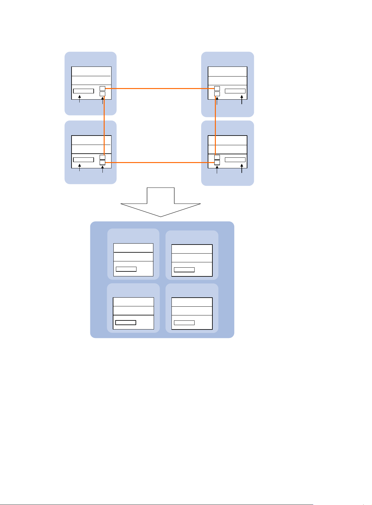
Figure 3 Four-chassis IRF fabric implementation schematic diagram
Device A
( Member ID=1 )
Active MPU
Standby MPU
Network
interfaces
Device C
( Member ID=3 )
Active MPU
Standby MPU
Network
interfaces
IRF-port1
IRF-port 2
IRF physical
ports
IRF-port1
IRF-port2
IRF physical
ports
IRF
Global active MPU
Global standby MPU
Master
IRF link
IRF is
formed.
IRF-port 2
IRF-port 1
IRF-port 2
IRF-port 1
Subordinate
( Member ID=2 )( Member ID=1 )
Global standby MPU
Global standby MPU
Device B
( Member ID=2 )
Active MPU
Standby MPU
IRF physical
ports
Device D
( Member ID=4 )
Active MPU
Standby MPU
IRF physical
ports
Network
interfaces
Network
interfaces
Global standby MPU
Global standby MPU
Operating mode
The device operates in one of the following modes:
• Standalone mode—The device cannot form an IRF fabric with other devices.
• IRF mode—The device can form an IRF fabric with other devices.
IRF member roles
IRF uses two member roles: master and standby (called "subordinate" throughout the documentation).
Subordinate
( Member ID=3 ) ( Member ID=4 )
Subordinate
Global standby MPU
Global standby MPU
4
Page 9

When devices form an IRF fabric, they elect a master to manage the IRF fabric, and all other devices back
up the master. When the master device fails, the other devices elect a new master automatically. For more
information about master election, see "Master election."
IRF member ID
An IRF fabric uses member IDs to uniquely identify and manage its members. If two devices have the
same IRF member ID, they cannot form an IRF fabric. If the IRF member ID of a device has been used in
an IRF fabric, the device cannot join the fabric.
Member ID information is included as the first part of interface numbers and file paths to uniquely
identify interfaces and files in an IRF fabric. For example, after you assign a device with member ID 2 to
an IRF fabric, the name of interface GigabitEthernet 3/0/1 changes to GigabitEthernet 2/3/0/1. The
file path changes from slot1#flash:/test.cfg to chassis2#slot1#flash:/test.cfg.
By default, the standby MPU of a device is assigned the same ID automatically as the active MPU. You
can change the standby MPU ID of one member device to quickly recover IRF configuration for another
member device that has only one MPU. The process is described in "Fast-restoring IRF configuration for
a one
-MPU member."
MPU roles
Each IRF member device has one or two MPUs. The following are roles that the MPUs play:
Role Description
Master MPU
Active MPU
Standby MPU
IRF port
An IRF port is a logical interface for the connection between IRF member devices. Every IRF-capable
device supports two IRF ports.
Active MPU of the master device. It is also called the "global active MPU." You
configure and manage the entire IRF fabric at the CLI of the global active MPU.
Active MPU on each member device. An active MPU has the following
responsibilities:
• Manages the local device, including synchronizing configuration with the
local standby MPU, processing protocol packets, and creating and
maintaining route entries.
• Handles IRF related events, such as master election and topology collection.
For the master MPU, all other MPUs, including active MPUs on subordinate
devices, are standby MPUs.
If a member device has two MPUs, the one backing up the local active MPU is
the local standby MPU from the perspective of the member device.
In standalone mode, the IRF ports are named IRF-port 1 and IRF-port 2.
In IRF mode, the IRF ports are named IRF-port n/1 and IRF-port n/2, where n is the member ID of the
device. The two IRF ports are referred to as "IRF-port 1" and "IRF-port 2" in this book for simplicity.
To use an IRF port, you must bind at least one physical port to it. The physical ports assigned to an IRF
port form an aggregate IRF link automatically. An IRF port goes down only if all its physical IRF ports are
down.
5
Page 10

For two neighboring devices, their IRF physical links must be bound to IRF-port 1 on one device and to
IRF-port 2 on the other.
IRF physical port
IRF physical ports connect IRF member devices and must be bound to an IRF port. They forward the IRF
protocol packets between IRF member devices and the data packets that must travel across IRF member
devices.
IRF domain ID
One IRF fabric forms one IRF domain. IRF uses IRF domain IDs to uniquely identify IRF fabrics and prevent
IRF fabrics from interfering with one another.
As shown in Figure 4, D
fabric 2. Both fabrics use the LACP aggregate links between them for MAD. When a member device
receives an extended LACP packet for MAD, it checks the domain ID to see whether the packet is from
the local IRF fabric or from a different IRF fabric. Then, the device can handle the packet correctly.
Figure 4 A network that contains two IRF domains
evice A and Device B form IRF fabric 1, and Device C and Device D form IRF
IRF split
IRF split occurs when an IRF fabric breaks up into two or more IRF fabrics because of IRF link failures, as
shown in Figure 5.
forwarding problems on the network. To quickly detect a multi-active collision, configure at least one
MAD mechanisms (see "IRF multi-active detection")
The split IRF fabrics operate with the same IP address and cause routing and
.
6
Page 11

To avoid a card removal causing an IRF split, bind physical ports on different cards to an IRF port.
Figure 5 IRF split
IRF merge
IRF merge occurs when two split IRF fabrics reunite or when two independent IRF fabrics are combined,
as shown in Figure 6.
Figure 6 IRF merge
IRF 1
IRF 2
+
Device A
Device B
Member priority
Member priority determines the possibility of a member device to be elected the master. A member with
higher priority is more likely to be elected the master.
The default member priority is 1. You can change the member priority of a device to affect the master
election result.
Master election
Master election is held each time the IRF fabric topology changes, for example, when the IRF fabric is
established, the master device fails or is removed, the IRF fabric splits, or active IRF fabrics merge. Master
election does not occur when two split IRF fabrics merge.
Master election uses the following rules in descending order:
IRF
=
XGE1/3/0/1
Device A Device B
XGE2/3/0/1
IRF link
1. Current master, even if a new member has higher priority.
When an IRF fabric is being formed, all member devices consider themselves as the master, and
this rule is skipped.
2. Member with higher priority.
3. Member with the longest system uptime.
Two members are considered starting up at the same time if their startup time difference is equal
to or less than 10 minutes. For these members, the next tiebreaker applies.
4. Member with the lowest CPU MAC address.
The IRF fabric is formed on election of the master.
7
Page 12

During an IRF merge, members of the IRF fabric that has failed the master election must reboot to rejoin
the IRF fabric that wins the election. The reboot can be performed automatically or manually, depending
on the configuration. See "Enabling IRF auto merge."
After a master election, all subordinate devices reboot with the configuration on the master. The
configuration files of the subordinate members are still retained, but these files do not take effect in the
IRF fabric. A subordinate member reboots with its own startup configuration file only when it is converted
to the standalone mode.
IRF multi-active detection
An IRF link failure causes an IRF fabric to split in two IRF fabrics operating with the same Layer 3
configurations, including the same IP address. To avoid IP address collision and network problems, IRF
uses multi-active detection (MAD) mechanisms to detect the presence of multiple identical IRF fabrics,
handle collisions, and recover from faults.
Multi-active handling procedure
The multi-active handling procedure includes detection, collision handling, and failure recovery.
Detection
The MAD implementation of this device detects active IRF fabrics with the same Layer 3 global
configuration by extending the LACP, BFD, ARP, or IPv6 ND protocol.
These MAD mechanisms identify each IRF fabric with a domain ID and an active ID (the member ID of
the master). If multiple active IDs are detected in a domain, MAD determines that an IRF collision or split
has occurred.
You can use at least one of these mechanisms in an IRF fabric, depending on your network topology.
IMPORTANT:
LACP MAD handles collisions differently than BFD MAD, ARP MAD, and ND MAD. To avoid conflicts, do
not use LACP MAD together with any of those mechanisms. However, you can use BFD MAD, ARP MAD,
and ND MAD together.
For a comparison of these MAD mechanisms, see "Configuring MAD."
Collision handling
When MAD detects a multi-active collision, it allows one IRF fabric to forward traffic and sets all the other
IRF fabrics to the Recovery state. The Recovery-state IRF fabrics are inactive and cannot forward traffic.
LACP MAD handles a multi-active collision in the following procedure:
1. Compares the number of members in each fabric.
2. Allows the fabric that has the most members to forward traffic, and sets all other fabrics to the
Recovery state.
3. Compares the member IDs of the masters if all IRF fabrics have the same number of members.
4. Allows the IRF fabric that has the lowest numbered master to forward traffic, and all other fabrics
to the Recovery (inactive) state. To avoid network flapping caused by IRF split, HP recommends
that you configure the lowest numbered member as the master in a two-chassis IRF fabric.
5. Shuts down all physical network ports in the Recovery-state fabrics except for the following ports:
8
Page 13

{ Physical IRF ports
{ Ports you have specified with the mad exclude interface command
In contrast, BFD MAD, ARP MAD, and ND MAD do not compare the number of members in fabrics.
These MAD mechanisms handle a multi-active collision in the following process:
6. Allow the IRF fabric that has the lowest numbered master to forward traffic.
7. Set all other fabrics to the Recovery state.
8. Take the same action on the network ports in Recovery-state fabrics as LACP MAD does.
Failure recovery
To merge two split IRF fabrics, first repair the failed IRF link and remove the IRF link failure.
If the IRF fabric in Recovery state fails before the failure is recovered, repair the failed IRF fabric and the
failed IRF link.
If the active IRF fabric fails before the failure is recovered, enable the inactive IRF fabric to take over the
active IRF fabric. Then, recover the MAD failure.
LACP MAD
LACP MAD requires that every IRF member have a link with an intermediate device, and all these links
form a dynamic link aggregation group, as shown in Figure 7. In addit
be an HP device that supports extended LACP for MAD.
ion, the intermediate device must
The IRF member devices send extended LACPDUs with TLVs that convey the domain ID and the active ID
of the IRF fabric. The intermediate device transparently forwards the extended LACPDUs received from
one member device to all the other member devices:
• If the domain IDs and the active IDs in the extended LACPDUs sent by all the member devices are
the same, the IRF fabric is integrated.
• If the extended LACPDUs convey the same domain ID but different active IDs, a split has occurred.
LACP MAD handles this situation as described in "Collision handling."
9
Page 14
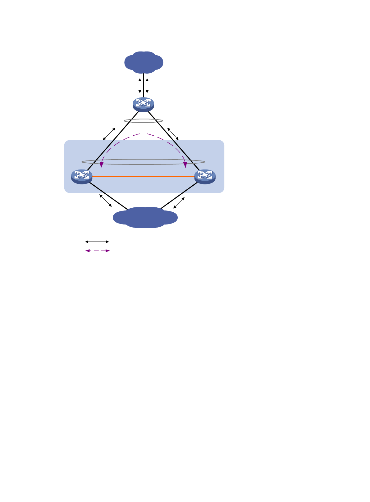
Figure 7 LACP MAD application scenario
Customer
premise
network
Intermediate device
LACP-enabled dynamic
link aggregation
IRF
LACP-enabled dynamic
link aggregation
IRF link
Master
Subordinate
BFD MAD
BFD MAD can work with or without intermediate devices. Figure 8 shows a typical BFD MAD application
scenario.
To use BFD MAD:
• Set up dedicated BFD MAD link between each pair of IRF members or between each IRF member
and the intermediate device. Only use the BFD MAD links for BFD MAD.
• Assign the ports connected by BFD MAD links to the same VLAN, create a VLAN interface for the
VLAN, and assign a MAD IP address to each member on the VLAN interface.
The MAD IP addresses identify the member devices and must belong to the same subnet.
With BFD MAD, the master tries to establish BFD sessions with the other member devices by using its
MAD IP address as the source IP address:
• If the IRF fabric is integrated, only the MAD IP address of the master is effective, and the master
cannot establish a BFD session with any other member. If you execute the display bfd session
command, the state of the BFD sessions is Down.
Internet
Common traffic path
LACP MAD traffic path
• When the IRF fabric splits, the IP addresses of the masters in the split IRF fabrics take effect, and the
two masters can establish a BFD session. If you use the display bfd session command, the state of
the BFD session between the two devices is Up.
10
Page 15

Figure 8 BFD MAD application scenario
Customer
premise
network
Device
Link aggregation
IRF
VLAN 2
192.168.1.2/24
BFD MAD link
VLAN 2
192.168.1.3/24
Master
ARP MAD
ARP MAD detects multi-active collisions by using extended ARP packets that convey the IRF domain ID
and the active ID.
You can set up ARP MAD links between neighbor IRF member devices, or between each IRF member
device and an intermediate device (see Figure 9)
spanning tree feature between the IRF fabric and the intermediate device.
IRF link
Subordinate
Internet
. If an i ntermediate device is used, you mus t also run the
11
Page 16

Figure 9 ARP MAD application scenario
Each IRF member compares the domain ID and the active ID in incoming extended ARP packets with its
domain ID and active ID:
• If the domain IDs are different, the extended ARP packet is from a different IRF fabric. The device
does not continue to process the packet with the MAD mechanism.
• If the domain IDs are the same, the device compares the active IDs:
{ If the active IDs are different, the IRF fabric has split.
{ If the active IDs are the same, the IRF fabric is integrated.
ND MAD
ND MAD detects multi-active collisions by using the ND protocol's NS packets to transmit the IRF domain
ID and the active ID.
You can set up ND MAD links between neighbor IRF member devices, or between each IRF member
device and an intermediate device (see Figure 10)
the spanning tree protocol between the IRF fabric and the intermediate device.
. If an intermediate device is used, you must also run
12
Page 17

Figure 10 ND MAD application scenario
Each IRF member device compares the domain ID and the active ID in incoming NS packets with its
domain ID and active ID:
• If the domain IDs are different, the NS packet is from a different IRF fabric. The device does not
continue to process the packet with the MAD mechanism.
• If the domain IDs are the same, the device compares the active IDs:
{ If the active IDs are different, the IRF fabric has split.
{ If the active IDs are the same, the IRF fabric is integrated.
13
Page 18

Configuring IRF
General restrictions and configuration guidelines
To ensure a successful IRF setup, read the configuration restrictions and guidelines carefully before you
connect and set up an IRF fabric.
Software requirements
All IRF member devices must run the same system software image version.
IRF size
A 12500 IRF fabric can have up to four chassis.
MPU and IRF physical port restrictions
MPU restrictions
When you set up an IRF fabric, follow these MPU restrictions and guidelines:
• Every IRF member must have at least one MPU.
• All member devices must use the same type of MPUs.
• To use enhanced IRF, make sure each IRF member has two MPUs.
Selecting IRF physical ports
You must use Layer 2 Ethernet fiber or copper ports for IRF connection. HP recommends using 10-GE fiber
ports for high performance.
IRF physical port binding restrictions
When you bind IRF physical ports to IRF ports, follow these restrictions and guidelines:
• Link aggregation member ports cannot be bound to an IRF port. To bind them to an IRF port, you
must first remove them from the aggregation group.
• If multiple physical links are used between two member chassis, bind them all to IRF-port 1 on one
chassis and to IRF-port 2 on the other. If the number of physical ports at the two ends of an
aggregate IRF link differs, the IRF fabric cannot be formed.
• In IRF mode, use the shutdown command to shut down a physical port before you bind it to or
remove it from an IRF port. In standalone mode, the shutdown operation is not required.
• Make sure you have brought up the IRF physical ports after you complete the binding operation.
Connecting IRF ports
When you connect two neighboring IRF members, connect the physical ports of IRF-port 1 on one
member to the physical ports of IRF-port 2 on the other.
14
Page 19

Suppose you have four chassis: A, B, C, and D. IRF-port 1 and IRF-port 2 are represented by A1 and A2
on chassis A, represented by B1 and B2 on chassis B, and so on. To connect the four chassis into a ring
topology of A-B-C-D(A), the IRF link cabling scheme must be one of the following:
• A1-B2, B1-C2, C1-D2, and D1-A2.
• A 2- B 1, B 2-C 1, C 2- D 1, a n d D 2- A 1.
IRF link redundancy
When you configure an IRF fabric, follow these redundancy restrictions and guidelines:
• For link redundancy and load sharing, bind up to 12 physical ports to one IRF port.
• Physical ports bound to an IRF port can be located on different cards.
• HP recommends using multicard IRF links to avoid a card removal causing an IRF split.
Multichassis link aggregation
For high availability, connect a downstream device to each IRF member device, and assign the links to
one link aggregation group. See Figure 22.
Feature and IRF mode compatibility
To form an IRF fabric:
• All member devices in the IRF fabric must use the same ACL hardware mode. For more information
about hardware-based ACLs, see ACL and QoS Configuration Guide.
• All member devices in the IRF fabric must have the same irf mode enhanced command
configuration.
• All member devices in the IRF fabric must work in the same system operating mode. For more
information about the system operating mode, see Fundamentals Configuration Guide.
MAD and IRF domain restrictions
When you configure an IRF fabric, follow these MAD and IRF domain restrictions and guidelines:
• If LACP MAD, ARP MAD, or ND MAD runs between two IRF fabrics, assign each fabric a unique IRF
domain ID. (For BFD MAD, this task is optional.)
• An IRF fabric has only one IRF domain ID.
{ You can change the IRF domain ID by using the following commands: irf domain, mad enable,
mad arp enable, or mad nd enable. The IRF domain IDs configured by using these commands
overwrite each other.
{ In an MDC environment, if you change the IRF domain ID in one MDC, the IRF domain IDs in
all other MDCs change automatically. The irf domain command is available only on the default
MDC. The mad enable, mad arp enable, and mad nd enable commands are available on any
MDCs.
• LACP MAD handles collisions differently than BFD MAD, ARP MAD, and ND MAD. To avoid
conflicts, do not use LACP MAD together with any of those mechanisms in an IRF fabric. However,
you can configure BFD MAD, ARP MAD, and ND MAD together in an IRF fabric for prompt IRF split
detection.
15
Page 20

gory
MDC
• To exclude a port from the shutdown action that is executed when an IRF fabric transits to the
Recovery state, use the mad exclude interface command. To bring up a port after the IRF fabric
transits to the Recovery state, you must use the mad restore command instead of the undo shutdown
command.
If the IRF fabric splits, do not change the MDC settings on any IRF member devices before they reunite.
Except for the commands in Table 1, all I
Table 1 IRF commands available on both default and non-default MDCs
Command cate
Display commands
MAD commands
For more information about MDC, see "Configuring MDC."
EVI restrictions
In IRF mode, any type of outbound policies (for example, the outbound QoS policy) on an interface does
not take effect on packets that are received from an EVI tunnel.
RF commands are available only on the default MDC.
Commands
display irf link
display mad
display port restricted
mad arp enable
mad bfd enable
mad enable
mad nd enable
mad exclude interface
mad ip address
Other configuration guidelines
• If a subordinate device uses the same next-startup configuration file name as the master device, the
file might be overwritten depending on your configuration file management settings. To continue to
use the configuration file after removing the device from the IRF fabric, back up the file before setting
up the IRF fabric.
• Strictly follow the IRF fabric setup procedure described in "Setup and configuration task list" to pla
the IRF fabric, identify IRF physical ports, connect IRF member devices, and configure basic settings.
• If two IRF fabrics have the same bridge MAC address, they cannot merge.
• Assign each member a unique IRF member ID to make sure they can merge. You must reboot the
members to validate the IRF member ID settings.
• Assign the highest member priority to the device you want to use as the master.
• Save any configuration you have made to the startup configuration file before you reboot the IRF
member devices.
n
16
Page 21

Setup and configuration task list
HP recommends the following IRF fabric setup and configuration procedure:
Setup and configuration procedure Remarks
1. (Required.) Planning the IRF fabric setup
2. (Required.) Preconfiguring IRF member devices in standalone mode:
{ Assigning a member ID to each IRF member device
{ Specifying a priority for each member device
{ Binding physical ports to IRF ports
3. (Optional.) Enabling enhanced IRF in standalone mode
N/A
Perform this task on each member
device before the IRF mode is
enabled.
If more than two devices are used to
form one IRF fabric, this step is
required.
4. (Required.) Saving configuration to the next-startup configuration file
5. (Required.) Connecting physical IRF ports
6. (Required.) Setting the operating mode to IRF mode
7. (Required.) Accessing the IRF fabric
8. (Optional.) Configuring IRF member devices in IRF mode:
{ Assigning an IRF domain ID to the IRF fabric
{ Changing the member ID of a device
{ Changing the priority of a member device
{ Adding physical ports to an IRF port
{ Enabling enhanced IRF in IRF mode
{ Enabling IRF auto merge
{ Configuring a member device description
{ Configuring IRF bridge MAC persistence
{ Enabling software auto-update for system software image
synchronization
{ Setting the IRF link down report delay
{ Configuring MAD
9. (Optional.) Fast-restoring IRF configuration for a one-MPU member
N/A
Make sure they are interoperable.
N/A
N/A
Adding physical ports to an IRF port
is required if you did not configure
IRF port bindings in standalone
mode.
If a two-chassis IRF fabric has new
joining members, you must enable
the enhanced IRF on each member
device.
CAUTION:
Changing member IDs in an IRF
fabric can void member ID-related
configuration and cause
unexpected problems. Before doing
that, make sure you understand the
impact on your live network.
This task helps you fast-restore IRF
configuration for one-MPU
members before an MPU
replacement.
Planning the IRF fabric setup
Consider the following items when you plan an IRF fabric:
• Hardware compatibility and restrictions
• IRF fabric size
• Master device
• IRF physical ports
17
Page 22

• Member ID and priority assignment scheme
• Fabric topology and cabling scheme
For more information about hardware and cabling, see the installation guide for the device.
Preconfiguring IRF member devices in standalone mode
Perform the tasks in this section on every IRF member device. These settings take effect on each member
device after their operating mode changes to IRF.
Assigning a member ID to each IRF member device
A device by default operates in standalone mode without an IRF member ID. You must assign it a unique
IRF member ID before changing its operating mode to IRF.
Execute the display irf configuration command and look at the MemberID field. If the device has no IRF
member ID, the field displays two hyphens (--).
The member ID assigned to a device is saved in both active and standby MPUs of the device. The standby
MPU might store a different member ID than the active MPU after an MPU replacement. When the
difference is detected, the system updates the member ID in the active MPU automatically to the standby
MPU for consistency.
To set a member ID for the device in standalone mode:
Step Command Remarks
1. Enter system view.
2. Assign an IRF member ID to
the device.
system-view N/A
irf member member-id
By default, the device has no IRF
member ID.
Specifying a priority for each member device
IRF member priority represents the possibility for a device to be elected the master in an IRF fabric. The
higher the priority, the higher the possibility.
To specify a priority for the device in standalone mode:
Step Command Remarks
1. Enter system view.
2. Specify a priority for the
device.
system-view N/A
irf priority priority
The default IRF member priority
is 1.
18
Page 23

Binding physical ports to IRF ports
To establish an IRF connection between two devices, you must bind at least one physical port to IRF-port
1 on one device and to IRF-port 2 on the other. For link redundancy and load sharing, bind multiple
physical ports to one IRF port.
Make sure the IRF physical ports are operating as Layer 2 interfaces. Layer 3 interfaces cannot be bound
to IRF ports. You can set a physical port as a Layer 2 or Layer 3 interface by using the port link-mode
{ bridge | route } command (see Interface Configuration Guide).
In standalone mode, binding a physical port to an IRF port does not affect the current configuration of the
port. However, when the operating mode changes to IRF mode, the default configuration of the physical
IRF port restores. You can only execute the description, flow-interval, and shutdown commands on the
physical port. For more information about these commands, see Interface Command Reference.
To bind physical ports to IRF ports:
Step Command Remarks
1. Enter system view.
system-view N/A
2. Enter IRF port view.
3. Bind a physical IRF port to
the IRF port.
4. Return to system view.
5. Enter physical IRF port view
or interface range view.
irf-port port-number N/A
By default, no physical ports are
bound to any IRF port.
Repeat this step to assign more
physical ports to the IRF port.
port group [ mdc mdc-id ] interface
interface-type interface-number
quit N/A
Each IRF port can have up to 12
physical ports.
HP recommends not creating
MDCs or binding ports on
non-default MDCs to an IRF port
when the device is operating in
standalone mode.
• Enter interface range view:
{ Method 1:
interface range { interface-type
interface-number [ to
interface-type
interface-number ] } &<1-5>
{ Method 2:
interface range name name
[ interface { interface-type
interface-number [ to
interface-type
interface-number ] } &<1-5> ]
To bring up a range of physical
IRF ports, enter interface range
view.
To bring up one physical IRF
port, enter its interface view.
• Enter interface view:
interface interface-type
interface-number
6. Bring up the port or ports.
7. Return to system view.
undo shutdown By default, all ports are down.
quit N/A
19
Page 24

Step Command Remarks
8. (Optional.) Verify the
binding result.
display irf configuration N/A
Enabling enhanced IRF in standalone mode
Enhanced IRF allows you to create a three- or four-chassis IRF fabric.
When you configure enhanced IRF on a standalone device, follow these restrictions and guidelines:
• Do not create MDCs on the device. The mdc mdc-name [ id mdc-id ] command is mutually exclusive
with the irf mode enhanced command. For more information about MDC, see "Configuring MDC."
• For a successful merge, make sure enhanced IRF is enabled or disabled on all member devices.
Devices that use different enhanced IRF settings cannot form an IRF fabric.
To enable enhanced IRF in standalone mode:
Step Command Remarks
1. Enter system view.
2. Enable enhanced IRF.
system-view N/A
By default, enhanced IRF is
disabled.
After enhanced IRF is enabled,
you cannot create Layer 3
Ethernet interfaces or
irf mode enhanced
subinterfaces or Layer 3
aggregate interfaces or
subinterfaces.
To disable enhanced IRF, use
the undo irf mode enhanced
command.
Saving configuration to the next-startup configuration file
Save the running configuration before converting to the IRF mode. The mode change requires a reboot,
which can cause all unsaved settings to be lost.
Perform the following task in any view:
Task Command
Save the running configuration to
the next-startup configuration file.
save [ safely ] [ backup | main ] [ force ]
20
Page 25

g
Connecting physical IRF ports
When you connect two neighboring IRF members, connect the physical ports of IRF-port 1 on one
member to the physical ports of IRF-port 2 on the other, as shown in Figure 11.
If c
opper Ethernet ports are used, use straight-through or crossover copper Ethernet cables to connect
them.
If fiber Ethernet ports are used, install transceiver modules and use fibers to connect them. For more
information about transceiver modules, see the device installation guide.
To connect two IRF member devices through SFP+ ports, you can use a fiber or an SFP+ cable.
Figure 11 Connecting IRF physical ports
Connect the devices into a daisy-chain topology or a ring topology. A ring topology is more reliable
(see Figure 12)
. In ring topology, the failure of one IRF link does not cause the IRF fabric to split as in
daisy-chain topology. Instead, the IRF fabric changes to a daisy-chain topology without interrupting
network services.
To use the ring topology, you must have at least three member devices.
Figure 12 Daisy-chain topology versus ring topology
IRF
Master
IRF-Port1
Subordinate
IRF-Port1
Subordinate
IRF-Port2
IRF-Port1 IRF-Port2
IRF-Port2
Subordinate Subordinate
IRF-Port2
Master
IRF
IRF-Port1
IRF-Port2IRF-Port1
Ring topology
Daisy-chain topology
As shown in Figure 13, you can use relay devices (for example, Layer 2 switches), to connect two IRF
member devices that are far away from each other.
IMPORTANT:
For enhanced IRF (four-chassis capability) to operate correctly, the IRF fabric must use the rin
topology
and must not have relay devices between member devices.
21
Page 26

g
Figure 13 Daisy-chain topology with a relay
Setting the operating mode to IRF mode
By default, the device is operating in standalone mode. To assign the device to an IRF fabric, you must
change its operating mode to IRF mode.
Before changing to IRF mode, use the display irf configuration command to verify that a member ID has
been assigned to the device. If the MemberID field displays two hyphens (--), first assign a member ID to
the device.
To set the operating mode of a device to IRF mode:
Step Command Remarks
1. Enter system view.
2. Set the operating mode to
IRF mode.
system-view N/A
chassis convert mode irf
The default operating mode is
standalone mode.
After you change the operating mode, the device reboots automatically to commit the change.
During the reboot, you may choose to have the system convert the startup configuration file automatically.
Automatic configuration conversion prevents slot- or interface-related configurations from becoming
invalid. For example, the system can convert the slot slot-number parameter set in standalone mode to the
chassis chassis-number slot slot-number parameter in IRF mode. The system can also add the chassis ID
in an interface number.
To restore the standalone mode, use the undo chassis convert mode command.
TIP:
IRF generates packets on a device in IRF mode even if the device does not form an IRF fabric with any other
device. To protect system resources, set a device to operate in standalone mode after removin
IRF fabric.
it from an
22
Page 27

g
Accessing the IRF fabric
The IRF fabric appears as one device after it is formed. You configure and manage all IRF members at the
CLI of the global active MPU. All settings you made are propagated automatically to the IRF members.
When you log in to an IRF fabric, you are placed at the CLI of the global active MPU, regardless of at
which member device you are logged in.
You can use the following methods to access an IRF fabric:
• Local login—Log in through the console or AUX port of a member device.
• Remote login—Remotely log in at a Layer 3 Ethernet interface on any member device by using
methods including Telnet, Web, and SNMP.
For more information, see the chapter on login in Fundamentals Configuration Guide.
Configuring IRF member devices in IRF mode
After you access the global active MPU's CLI, you can perform the tasks in this section or configure
features in all other configuration guides for the device.
Assigning an IRF domain ID to the IRF fabric
This task is required for running LACP MAD, ARP MAD, or ND MAD between two IRF fabrics. For BFD
MAD, this task is optional.
One IRF fabric forms one IRF domain. IRF domain IDs prevent IRF fabrics from interfering with one
another.
To assign a domain ID to an IRF fabric:
Step Command Remarks
1. Enter system view.
2. Assign a domain ID to the
IRF fabric.
system-view N/A
irf domain domain-id By default, the domain ID of an IRF fabric is 0.
Changing the member ID of a device
CAUTION:
In IRF mode, an IRF member ID change can invalidate member ID-related settin
sure you fully understand its impact on your live network.
s and cause data loss. Be
The new member ID takes effect at reboot. After the device reboots, the settings on all member ID related
physical resources (including common physical network ports) are removed, regardless of whether you
have saved the configuration.
To change the member ID of a member device:
23
Page 28

Step Command Remarks
1. Enter system view.
system-view N/A
2. Change the member ID of a
member device.
3. Save the running
configuration.
4. Reboot the member device.
irf member member-id renumber
new-member-id
save [ safely ] [ force ] N/A
reboot chassis chassis-number
Changing the priority of a member device
You can change the priority of a member device so it can be elected the master at the next master
election.
A member priority change can affect the master re-election result, but does not cause immediate master
re-election.
To change the priority of a member device:
Step Command Remarks
1. Enter system view.
system-view N/A
N/A
The chassis-number must be the
same as the member-id specified
in the irf member member-id
renumber new-member-id
command.
2. Specify a priority for a
member of an IRF fabric.
irf member member-id priority priority
Adding physical ports to an IRF port
An IRF port can have up to 12 physical ports. In IRF mode, you can add more physical ports to an IRF port.
This task does not affect the ongoing traffic on the IRF port.
When you perform this task, follow the IRF physical port restrictions and configuration guidelines in
"MPU and IRF physical port restrictions" and "Binding physical ports to IRF ports."
To configure IRF ports:
Step Command Remarks
1. Enter system view.
system-view N/A
The default IRF member priority
is 1.
24
Page 29

Step Command Remarks
• Enter interface range view:
{ Method 1:
interface range { interface-type
interface-number [ to
interface-type
2. Enter Ethernet interface view
or interface range view.
interface-number ] } &<1-5>
{ Method 2:
interface range name name
[ interface { interface-type
interface-number [ to
To shut down a range of physical
IRF ports, enter interface range
view.
To shut down one physical IRF
port, enter its interface view.
interface-type
interface-number ] } &<1-5> ]
• Enter interface view:
interface interface-type
interface-number
3. Shut down the port or ports.
4. Return to system view.
5. Enter IRF port view.
6. Bind each physical port to
the IRF port.
7. Return to system view.
8. Enter physical IRF port view
or interface range view.
shutdown By default, all ports are down.
quit N/A
irf-port member-id/port-number N/A
By default, no physical ports are
bound to any IRF port.
Repeat this step to assign
multiple physical ports to the IRF
port group [ mdc mdc-id ] interface
interface-type interface-number
port for link redundancy.
You can bind up to 12 physical
ports to an IRF port.
The binding attempt will fail if
you have bound 12 physical
ports to the IRF port
quit N/A
• Enter interface range view:
{ Method 1:
interface range { interface-type
interface-number [ to
interface-type
interface-number ] } &<1-5>
{ Method 2:
interface range name name
N/A
[ interface { interface-type
interface-number [ to
interface-type
interface-number ] } &<1-5> ]
• Enter interface view:
interface interface-type
interface-number
9. Bring up the port or ports.
10. Return to system view.
undo shutdown N/A
quit
N/A
25
Page 30

Step Command Remarks
11. Save the running
configuration.
12. Activate the configuration on
the IRF port.
save
irf-port-configuration active
Enabling enhanced IRF in IRF mode
Activating IRF port
configurations can cause IRF
merge and reboot. To avoid
data loss, save the running
configuration to the startup
configuration file before you
perform the operation.
After this step is performed, the
state of the IRF port changes to
UP, the member devices
automatically elect a master,
and the subordinate device
automatically reboots.
After the IRF fabric is formed,
you can add more physical ports
to an IRF port (in UP state)
without performing this step.
Configuration prerequisites
Before you enable enhanced IRF in IRF mode, complete the following tasks:
• Remove MDCs in the IRF fabric. The mdc mdc-name [ id mdc-id ] command is mutually exclusive
with the irf mode enhanced command.
• If Layer 3 (route mode) Ethernet interfaces exist, you must change the operating mode of these
interfaces to Layer 2 (bridge mode). You can enable enhanced IRF only when the device does not
have Layer 3 (route mode) Ethernet interfaces. For more information about the operating modes of
Ethernet interfaces, see Interface Configuration Guide.
Configuration restrictions and guidelines
When you configure enhanced IRF in IRF mode, follow these restrictions and guidelines:
• For a successfully IRF merge, make sure enhanced IRF is enabled or disabled on each member
device.
• To merge IRF fabrics operating in enhanced IRF, you must manually reboot at least the (M-1) member
devices to complete the IRF merge. (The letter "M" represents the total number of member devices
in all IRF fabrics.)
• To disable enhanced IRF in IRF mode, make sure the following requirements are met:
{ The IRF fabric has no more than two member devices.
{ Only one IRF port on each member device has physical port bindings.
• The system will reboot automatically after you execute the undo irf mode enhanced command. To
avoid data loss, follow the system instruction to save the running configuration when you execute the
command.
Configuration procedure
To enable enhanced IRF:
26
Page 31

Step Command Remarks
1. Enter system view.
2. Enable enhanced IRF.
system-view N/A
By default, enhanced IRF is
disabled.
After enhanced IRF is enabled,
irf mode enhanced
you cannot create Layer 3
Ethernet interfaces or
subinterfaces or Layer 3
aggregate interfaces or
subinterfaces.
3. Save the configuration.
4. (Optional.) Reboot the IRF fabric.
Enabling IRF auto merge
When t wo IRF fabrics merge, you must reboot the member devices in th e IRF fabric that fails in the master
election. The auto merge function enables the IRF fabric to reboot all its member devices automatically to
complete the merge.
This function can work only when it is enabled on both IRF fabrics that are merging.
The IRF auto merge function does not take effect on the IRF fabric merge caused by binding a physical
port to an IRF port in IRF mode. You must manually reboot the devices that have been defeated in the
master election to complete the merge.
To enable IRF auto merge:
Step Command Remarks
1. Enter system view.
save [ safely ] [ force ] N/A
If the IRF fabric has SPB VSIs,
you must reboot the IRF fabric,
reboot
system-view N/A
for enhanced IRF to take effect.
For more information about
SPB, see SPB Configuration
Guide.
2. Enable IRF auto merge.
irf auto-merge enable
Configuring a member device description
You can configure a description to describe the location or purpose of a member device.
To configure a description for a member device:
Step Command Remarks
1. Enter system view.
2. Configure the description of
a member.
system-view N/A
irf member member-id description text
27
By default, this function is
disabled.
By default, no member device
description is configured.
Page 32

t
Configuring IRF bridge MAC persistence
By default, an IRF fabric uses the bridge MAC address of the master device as its bridge MAC address.
Layer 2 protocols, such as LACP, use this bridge MAC address to identify the IRF fabric. On a switched
LAN, the bridge MAC address must be unique.
To avoid duplicate bridge MAC addresses, an IRF fabric can change its bridge MAC address
automatically after its master leaves. However, the change can cause transient traffic disruption.
Depending on your network condition, enable the IRF fabric to preserve or change its bridge MAC
address after the master leaves. Available options include:
• irf mac-address persistent timer—Bridge MAC address of the IRF fabric is retained for 6 minutes
after the master leaves. If the master does not return before the timer expires, the IRF fabric uses the
bridge MAC address of the new master as its bridge MAC address. This option avoids unnecessary
bridge MAC address change due to a device reboot, transient link failure, or purposeful link
disconnection.
• irf mac-address persistent always—Bridge MAC address of the IRF fabric does not change after
the master leaves.
• undo irf mac-address persistent—Bridge MAC address of the new master replaces the original one
as soon as the old master leaves.
IMPORTANT:
• If ARP MAD or ND MAD is used, configure the undo irf mac-address persistent command to enable
immediate bridge MAC address change after a master leaves.
• If VRRP load balancing is used, configure the irf mac-address persistent always command to preven
the IRF bridge MAC address from changing. For more information about VRRP, see
Configuration Guide
.
High Availability
If two IRF fabrics have the same bridge MAC address, they cannot merge.
To configure the IRF bridge MAC persistence setting:
Step Command Remarks
1. Enter system view.
system-view N/A
• Retain the bridge MAC address
even if the master has changed:
irf mac-address persistent always
2. Configure IRF bridge MAC
persistence.
• Preserve the bridge MAC address
for 6 minutes after the master
leaves:
irf mac-address persistent timer
By default, the IRF fabric's
bridge MAC address is retained
permanently even after the
master leaves.
• Change the bridge MAC address
as soon as the master leaves:
undo irf mac-address persistent
28
Page 33

d
Enabling software auto-update for system software image synchronization
IMPORTANT:
To ensure a successful software auto-update in a multi-user environment, prevent users from rebooting
MPUs or member devices during the software auto-update process. You can configure the information
center to output the software auto-update status to configuration terminals (see
Monitoring Configuration Guide
).
To synchronize software from the active MPU to the standby MPU in standalone mode, use the undo
version check ignore and version auto-update enable commands. For more information about these
commands, see Fundamentals Configuration Guide.
To synchronize software from the global active MPU to other MPUs on an IRF fabric, use the software
auto-update function in this section.
The software auto-update function propagates the software images of the global active MPU
automatically to all other MPUs in the IRF fabric.
To join an IRF fabric, an MPU must use the same software images as the global active MPU in the fabric.
When you add an MPU to the IRF fabric, software auto-update compares the startup software images of
the MPU with the current software images of the IRF global active MPU. If the two sets of images are
different, the MPU performs the following tasks automatically:
Network Management an
1. Downloads the current software images of the global active MPU.
2. Sets the downloaded images as the main startup software images.
3. Reboots with the new software images to rejoin the IRF fabric.
If software auto-update is disabled, you must manually update the MPU with the software images of the
global active MPU before adding the MPU to the IRF fabric.
Configuration prerequisites
Before you use the software auto-update function, verify the following items:
• The MPU you are adding to the IRF fabric is compatible with the software version running on the
global active MPU. If the software versions are not compatible, the software auto-update function
cannot correctly work.
• The MPU you are adding to the IRF fabric has sufficient space for the new software images.
Configuration procedure
To enable an IRF fabric to synchronize software images of the global active MPU automatically to the
MPUs you are adding to the IRF fabric:
Step Command Remarks
1. Enter system view.
2. Enable software
auto-update.
system-view N/A
irf auto-update enable
By default, this function is
enabled.
29
Page 34

Setting the IRF link down report delay
You can avoid link flapping causing frequent IRF splits and merges during a short time by configuring the
IRF ports to delay reporting link down events. An IRF port works as follows:
• When the IRF link changes from up to down, the port does not immediately report the change to the
IRF fabric. If the IRF link state is still down when the delay time is reached, the port reports the
change to the IRF fabric.
• When the IRF link changes from down to up, the link layer immediately reports the event to the IRF
fabric.
To set the IRF link down report delay:
Step Command Remarks
1. Enter system view.
2. Set the IRF link down report
delay.
system-view N/A
irf link-delay interval
The default IRF link down report delay is 0
seconds.
Recommended value range is 200 to 500
milliseconds. The greater the interval, the
slower the service recovery.
Configuring MAD
The following MAD mechanisms are available for detecting multi-active collisions in different network
scenarios:
• LACP MAD
• BFD MAD
• ARP MAD
• ND MAD
LACP MAD handles collisions differently than BFD MAD, ARP MAD, and ND MAD. To avoid conflicts, do
not enable LACP MAD together with any of these mechanisms in an IRF fabric. However, you can use
BFD MAD with ARP MAD or ND MAD.
Table 2 pr
Table 2 A comparison of the MAD mechanisms
MAD
mechanism
LACP MAD
ovides a reference for you to make a MAD mechanism selection decision.
Advantages Disadvantages Application scenario
• Detection speed is fast.
• Requires no MAD-dedicated
physical ports or interfaces.
Requires an intermediate HP
device that supports
extended LACP for MAD.
Link aggregation is used
between the IRF fabric
and its upstream or
downstream device.
For information about
LACP, see Layer 2—LAN
Switching Configuration
Guide.
30
Page 35

MAD
mechanism
BFD MAD
ARP MAD
ND MAD
Advantages Disadvantages Application scenario
• No special
requirements for
network scenarios.
• If no intermediate
device is used, this
mechanism is only
suitable for IRF fabrics
that have a small
number of members
that are
geographically close
to one another.
For information about
BFD, see High
Availability
Configuration Guide.
Spanning tree-enabled
non-link aggregation IPv4
network scenario.
For information about
ARP, see Layer 3—IP
Services Configuration
Guide.
Spanning tree-enabled
non-link aggregation IPv6
network scenario.
• Detection speed is fast.
• No intermediate device is
required.
• Intermediate device, if used,
can come from any vendor.
• No intermediate device is
required.
• Intermediate device, if used,
can come from any vendor.
• Requires no MAD dedicated
ports.
• No intermediate device is
required.
• Intermediate device, if used,
can come from any vendor.
• Requires no MAD dedicated
ports.
• Requires MAD dedicated
physical ports and Layer
3 interfaces, which
cannot be used for
transmitting user traffic.
• If no intermediate device
is used, the IRF members
must be fully meshed.
• If an intermediate device
is used, every IRF
member must connect to
the intermediate device.
• Detection speed is slower
than BFD MAD and LACP
MAD.
• The spanning tree feature
must be enabled.
• Detection speed is slower
than BFD MAD and LACP
MAD.
• The spanning tree feature
must be enabled.
Configuring LACP MAD
When you use LACP MAD, follow these guidelines:
• The intermediate device must be an HP device that support extended LACP for MAD.
• If the intermediate device is also an IRF fabric, assign the two IRF fabrics different domain IDs for
correct split detection. False detection causes IRF split.
• Use dynamic link aggregation mode. MAD is LACP dependent. Even though LACP MAD can be
configured on both static and dynamic aggregate interfaces, it takes effect only on dynamic
aggregate interfaces.
• Configure link aggregation settings also on the intermediate device.
To configure LACP MAD:
Step Command Remarks
1. Enter system view.
system-view N/A
31
Page 36

Step Command Remarks
The default IRF domain ID is 0.
2. Assign a domain ID to the IRF
fabric.
irf domain domain-id
This command can be executed
only on the default MDC
(Admin).
• Enter Layer 2 aggregate interface
view:
3. Create an aggregate
interface and enter
aggregate interface view.
4. Configure the aggregation
group to operate in dynamic
aggregation mode.
5. Enable LACP MAD.
interface bridge-aggregation
interface-number
• Enter Layer 3 aggregate interface
view:
interface route-aggregation
interface-number
link-aggregation mode dynamic
mad enable
Use either command.
Perform this step also on the
intermediate device.
By default, an aggregation
group operates in static
aggregation mode.
Perform this step also on the
intermediate device.
By default, LACP MAD is
disabled.
When you use the mad enable
command, the system prompts
you to enter a domain ID. If you
do not want to change the
current domain ID, press enter at
the prompt.
6. Return to system view.
7. Enter Ethernet interface view
or interface range view.
8. Assign the Ethernet port or
the range of Ethernet ports to
the specified aggregation
group.
Configuring BFD MAD
quit N/A
• Enter interface range view:
{ Method 1:
interface range { interface-type
interface-number [ to
interface-type
interface-number ] } &<1-5>
{ Method 2:
interface range name name
[ interface { interface-type
interface-number [ to
interface-type
To assign a range of ports to the
aggregation group, enter
interface range view.
To assign one port to the
aggregation group, enter
Ethernet interface view.
interface-number ] } &<1-5> ]
• Enter Ethernet interface view:
interface interface-type
interface-number
Multichassis link aggregation is
port link-aggregation group number
allowed.
Perform this step on the
intermediate device as well.
When you configure BFD MAD, follow these guidelines:
32
Page 37

g
Category Restrictions and
uidelines
• Do not enable BFD MAD on VLAN-interface 1.
• If you are using an intermediate device, assign the ports of BFD MAD links to
the BFD MAD VLAN on the device.
BFD MAD VLAN
• The IRF fabrics in a network must use different BFD MAD VLANs.
• If a trunk port is assigned to the BFD MAD VLAN, make sure the default
VLAN of tha t p ort is not used for BFD M A D. If you configure the default VL AN
to perform BFD MAD, other services configured on the port cannot work
correctly.
Do not use the BFD MAD VLAN for any purpose other than configuring BFD
MAD.
• Configure only the mad bfd enable and mad ip address commands on the
BFD MAD VLAN and feature
compatibility
BFD MAD-enabled VLAN interface. If you configure other features, both BFD
MAD and other features on the interface might run incorrectly.
• Disable the spanning tree feature on any port in the BFD MAD VLAN. The
MAD function is mutually exclusive with the spanning tree feature.
• Do not bind a BFD MAD-enabled VLAN interface to any VPN instance. The
MAD function is mutually exclusive with VPN.
• To avoid problems, only use the mad ip address command to configure IP
addresses on the BFD MAD-enabled VLAN interface. Do not configure an IP
MAD IP address
address with the ip address command or configure a VRRP virtual address on
the BFD MAD-enabled VLAN interface.
• All MAD IP addresses on the BFD MAD-enabled VLAN interface must be on
the same subnet.
To configure BFD MAD:
Step Command Remarks
1. Enter system view.
2. (Optional.) Assign a domain
ID to the IRF fabric.
3. Create a new VLAN
dedicated to BFD MAD.
4. Return to system view.
system-view N/A
By default, the domain ID of an
irf domain domain-id
vlan vlan-id
quit N/A
IRF fabric is 0.
This command can be executed
only on the default MDC.
The default VLAN on the device
is VLAN 1.
33
Page 38

Step Command Remarks
• Enter interface range view:
{ Method 1:
interface range { interface-type
interface-number [ to
5. Enter Ethernet interface view
or interface range view.
interface-type
interface-number ] } &<1-5>
{ Method 2:
interface range name name
[ interface { interface-type
interface-number [ to
interface-type
interface-number ] } &<1-5> ]
To assign a range of ports to the
BFD MAD VLAN, enter interface
range view.
To assign one port to the BFD
MAD VLAN, enter Ethernet
interface view.
• Enter Ethernet interface view:
interface interface-type
interface-number
• Assign the port to the VLAN as an
access port:
port access vlan vlan-id
6. Assign the port or the range
of ports to the BFD MAD
VLAN.
• Assign the port to the VLAN as a
trunk port:
port trunk permit vlan vlan-id
• Assign the port to the VLAN as a
hybrid port:
port hybrid vlan vlan-id { tagged |
untagged }
The link type of BFD MAD ports
can be access, trunk, or hybrid.
The default link type of a port is
access.
7. Return to system view.
8. Enter VLAN interface view.
9. Enable BFD MAD.
10. Configure a MAD IP address
for a member on the VLAN
interface.
Configuring ARP MAD
When you configure ARP MAD, follow these guidelines:
• Do not use the VLAN configured for ARP MAD for any other purposes.
• You cannot enable ARP MAD on VLAN-interface 1.
• If an intermediate device is used, you can use common data links as ARP MAD links. If no
intermediate device is used, set up dedicated ARP MAD links between IRF member devices.
quit N/A
interface vlan-interface
interface-number
mad bfd enable
mad ip address ip-address { mask |
mask-length } member member-id
N/A
By default, BFD MAD is
disabled.
By default, no MAD IP address is
configured on any VLAN
interface.
Repeat this step to assign a MAD
IP address to each member
device on the VLAN interface.
The MAD IP addresses identify
the member devices and must
belong to the same subnet.
• If an intermediate device is used, make sure the following requirements are met:
34
Page 39

{ Run the spanning tree feature between the IRF fabric and the intermediate device.
{ Enable the IRF fabric to change its bridge MAC address as soon as the master leaves.
{ Create an ARP MAD VLAN and assign the ports on the ARP MAD links to the VLAN.
{ If the intermediate device is also an IRF fabric, assign the two IRF fabrics different domain IDs
for correct split detection.
To configure ARP MAD:
Step Command Remarks
1. Enter system view.
system-view N/A
2. Assign a domain ID to the IRF
fabric.
3. Configure the IRF bridge
MAC address to change as
soon as the master leaves.
4. Create a VLAN dedicated to
ARP MAD.
5. Return to system view.
6. Enter Ethernet interface view
or interface range view.
7. Assign the port or the range
of ports to the ARP MAD
VLAN.
The default IRF domain ID is 0.
irf domain domain-id
This command can be executed
only on the default MDC.
By default, the IRF fabric's
undo irf mac-address persistent
bridge MAC address persists
permanently after the master
leaves.
vlan vlan-id
The default VLAN on the device
is VLAN 1.
quit N/A
• Enter interface range view:
{ Method 1:
interface range { interface-type
interface-number [ to
interface-type
interface-number ] } &<1-5>
{ Method 2:
interface range name name
[ interface { interface-type
interface-number [ to
interface-type
To assign a range of ports to the
ARP MAD VLAN, enter interface
range view.
To assign one port to the ARP
MAD VLAN, enter Ethernet
interface view.
interface-number ] } &<1-5> ]
• Enter Ethernet interface view:
interface interface-type
interface-number
• Assign the port to the VLAN as an
access port:
port access vlan vlan-id
• Assign the port to the VLAN as a
trunk port:
port trunk permit vlan vlan-id
• Assign the port to the VLAN as a
hybrid port:
port hybrid vlan vlan-id { tagged |
untagged }
The link type of ARP MAD ports
can be access, trunk, or hybrid.
The default link type of a port is
access.
8. Return to system view.
9. Enter VLAN interface view.
quit N/A
interface vlan-interface
interface-number
N/A
35
Page 40

Step Command Remarks
10. Assign the interface an IP
address.
11. Enable ARP MAD.
Configuring ND MAD
When you configure ND MAD, follow these guidelines:
• Do not use the VLAN configured for ND MAD for any other purposes.
• You cannot enable ND MAD on VLAN-interface 1.
• If an intermediate device is used, you can use common data links as ND MAD links. If no
intermediate device is used, set up dedicated ND MAD links between IRF member devices.
• If an intermediate device is used, make sure the following requirements are met:
ip address ip-address { mask |
mask-length }
mad arp enable
By default, no IP address is
assigned to any VLAN interface.
By default, ARP MAD is
disabled.
When you use the mad arp
enable command, the system
prompts you to enter a domain
ID. If you do not want to change
the current domain ID, press
enter at the prompt.
{ Run the spanning tree feature between the IRF fabric and the intermediate device.
{ Enable the IRF fabric to change its bridge MAC address as soon as the master leaves.
{ Create a ND MAD VLAN and assign the ports on the ND MAD links to the VLAN.
{ If the intermediate device is also an IRF fabric, assign the two IRF fabrics different domain IDs
for correct split detection.
To configure ND MAD:
Step Command Remarks
1. Enter system view.
2. Assign a domain ID to the IRF
fabric.
3. Configure the IRF bridge
MAC address to change as
soon as the master leaves.
4. Create a VLAN dedicated to
ND MAD.
5. Return to system view.
system-view N/A
irf domain domain-id The default IRF domain ID is 0.
By default, the IRF fabric's
undo irf mac-address persistent
bridge MAC address persists
permanently after the master
leaves.
vlan vlan-id
The default VLAN on the device
is VLAN 1.
quit N/A
36
Page 41

Step Command Remarks
• Enter interface range view:
{ Method 1:
interface range { interface-type
interface-number [ to
6. Enter Ethernet interface view
or interface range view.
interface-type
interface-number ] } &<1-5>
{ Method 2:
interface range name name
[ interface { interface-type
interface-number [ to
interface-type
interface-number ] } &<1-5> ]
To assign a range of ports to the
ND MAD VLAN, enter interface
range view.
To assign one port to the ND
MAD VLAN, enter Ethernet
interface view.
• Enter Ethernet interface view:
interface interface-type
interface-number
• Assign the port to the VLAN as an
access port:
port access vlan vlan-id
7. Assign the port or the range
of ports to the ND MAD
VLAN.
• Assign the port to the VLAN as a
trunk port:
port trunk permit vlan vlan-id
• Assign the port to the VLAN as a
hybrid port:
port hybrid vlan vlan-id { tagged |
untagged }
The link type of ND MAD ports
can be access, trunk, or hybrid.
The default link type of a port is
access.
8. Return to system view.
9. Enter VLAN interface view.
10. Assign the interface an IPv6
address.
11. Enable ND MAD.
quit N/A
interface vlan-interface
interface-number
ipv6 address
{ ipv6-address/pre-length | ipv6
address pre-length }
mad nd enable By default, ND MAD is disabled.
N/A
By default, no IPv6 address is
assigned to any VLAN interface.
Excluding a port from the shutdown action upon detection of multi-active collision
By default, all ports (except the console and physical IRF ports) shut down automatically when the IRF
fabric transits to the Recovery state.
You can exclude a port from the shutdown action for management or other special purposes. For
example:
• Exclude a port from the shutdown action, so you can Telnet to the port for managing the device or
use the port for MAD.
• Exclude a VLAN interface and its Layer 2 ports from the shutdown action, so you can log in through
the VLAN interface.
CAUTION:
Excluding a VLAN interface and its Layer 2 ports from the shutdown action introduces IP collision risks
because the VLAN interface might be active on both the active and inactive IRF fabrics.
To configure a port to not shut down when the IRF fabric transits to the Recovery state:
37
Page 42

Step Command Remarks
1. Enter system view.
system-view N/A
2. Configure a port to not shut
down when the IRF fabric
transits to the Recovery state.
Recovering an IRF fabric
After the failed IRF link between two split IRF fabrics is recovered, log in to the inactive IRF fabric, and use
the reboot command to reboot all its members. If the irf auto-merge enable command has been
configured, the inactive IRF member devices reboot automatically after the failed link is recovered. After
these member devices join the active IRF fabric as subordinates, IRF merge is complete, as shown
in Figure 14.
Figure 14 Recovering the IRF fabric
IP network
IRF 1
(Active)
mad exclude interface interface-type
interface-number
Network ports that
IRF 2
(Inactive)
have been shut
down
IRF link
recovered
By default, all network ports on a
Recovery-state IRF fabric are shut
down, except for the IRF physical
ports and console port.
IP network
IRF
Network ports that
have been shut down
IP network
IP network
If the active IRF fabric has failed before the IRF link is recovered (see Figure 15), use the mad restore
command on the inactive IRF fabric to recover the inactive IRF fabric. The command also brings up all
physical ports that were shut down by MAD. After you repair the IRF link, the two parts merge into a
unified IRF fabric.
38
Page 43

Figure 15 Active IRF fabric fails before the IRF link is recovered
To manually recover an inactive IRF fabric:
Step Command
1. Enter system view.
system-view
2. Recover the inactive IRF fabric.
mad restore
After the IRF fabric is recovered, all ports that have been shut down by MAD come up automatically.
Fast-restoring IRF configuration for a one-MPU member
CAUTION:
Use the irf slot member command only for fast-restoring IRF configuration. This command might cause
errors in other application scenarios.
If a member device has only one MPU, you must reconfigure the basic IRF settings for the device after its
MPU is damaged. This section describes a fast approach to restoring IRF configuration for one-MPU
member devices.
NOTE:
HP recommends performing fast IRF configuration restoration in IRF mode.
The recovery procedure differs depends on whether a two-member device is available. This section
assumes that the failed member device is Device A.
If a two-MPU member device (Device B in this example) is available, use the following procedure:
Step Command
1. Save the running configuration to the
configuration file used at the next startup.
save [ safely ] [ force ]
39
Page 44

Step Command
• In IRF mode:
2. Change Device B's member ID on the standby
MPU to be the same as that of Device A.
3. Remove the damaged MPU from Device A, and
insert Device B's standby MPU into Device A.
If each member device has only one MPU, use the following procedure:
irf chassis chassis-number slot slot-number member
member-id
• In standalone mode:
irf slot slot-number member member-id
N/A
Step Command
1. Save the running configuration to the
configuration file used at the next startup.
2. Insert a new MPU into any member device
working correctly, for example, Device B.
3. Copy the configuration file on Device B's
active MPU to the standby MPU.
save [ safely ] [ force ]
N/A
copy fileurl-source fileurl-dest
4. Set the configuration file for next startup.
startup saved-configuration cfgfile
• In IRF mode:
5. Change Device B's member ID on the standby
MPU to be the same as that of Device A.
6. Remove the damaged MPU from Device A,
and insert Device B's standby MPU into
Device A.
irf chassis chassis-number slot slot-number member
member-id
• In standalone mode:
irf slot slot-number member member-id
N/A
Displaying and maintaining an IRF fabric
Execute display commands in any view.
Task Command
Display information about all IRF members. display irf
Display the IRF fabric topology. display irf topology
Display IRF link information. display irf link
Display basic IRF settings. display irf configuration
Display MAD configuration. display mad [ verbose ]
Display restricted ports.
display port restricted [ chassis chassis-number [ slot
slot-number ] ]
40
Page 45

Configuration examples
This section provides IRF configuration examples for two-chassis and four-chassis IRF fabrics that use
different MAD mechanisms.
By default, Ethernet, VLAN, and aggregate interfaces are shut down. You must use the undo shutdown
command to bring them up.
LACP MAD-enabled IRF configuration example for a two-chassis IRF fabric
Network requirements
As shown in Figure 16, set up a two-chassis IRF fabric at the access layer of the enterprise network.
Configure LACP MAD on the mul tichassis aggregation to D evice C, an HP device that suppor ts extended
LACP.
Figure 16 Network diagram
Configuration procedure
IMPORTANT:
Between two neighboring IRF members, IRF links must be bound to IRF-port 1 on one member and to
IRF-port 2 on the other.
1. Configure Device A:
# Assign member ID 1 to Device A, and bind Ten-GigabitEthernet 3/0/1 to IRF-port 2.
<Sysname> system-view
[Sysname] irf member 1
Info: Member ID change will take effect after the member reboots and operates in IRF
mode.
[Sysname] irf-port 2
[Sysname-irf-port2] port group interface ten-gigabitethernet 3/0/1
41
Page 46

[Sysname-irf-port2] quit
[Sysname] interface ten-gigabitethernet 3/0/1
[Sysname-Ten-GigabitEthernet3/0/1] undo shutdown
[Sysname-Ten-GigabitEthernet3/0/1] quit
# Save the configuration.
[Sysname] quit
<Sysname> save
# Enable IRF mode.
<Sysname> system-view
[Sysname] chassis convert mode irf
The device will switch to IRF mode and reboot. You are recommended to save the current
running configuration and specify the configuration file for the next startup.
Continue? [Y/N]:y
Do you want to convert the content of the next startup configuration file
flash:/startup.cfg to make it available in IRF mode? [Y/N]:y
Please wait...
Saving the converted configuration file to the main board succeeded.
Slot 1:
Saving the converted configuration file succeeded.
Now rebooting, please wait...
2. Configure Device B:
# Assign member ID 2 to Device B, and bind Ten-GigabitEthernet 3/0/1 to IRF-port 1.
<Sysname> system-view
[Sysname] irf member 2
Info: Member ID change will take effect after the member reboots and operates in IRF
mode.
[Sysname] irf-port 1
[Sysname-irf-port1] port group interface ten-gigabitethernet 3/0/1
[Sysname-irf-port1] quit
[Sysname] interface ten-gigabitethernet 3/0/1
[Sysname-Ten-GigabitEthernet3/0/1] undo shutdown
[Sysname-Ten-GigabitEthernet3/0/1] quit
# Save the configuration.
[Sysname] quit
<Sysname> save
# Connect the two devices as shown in Figure 16.
# Log in to Device B. (Details not shown.)
# Enable IRF mode.
<Sysname> system-view
[Sysname] chassis convert mode irf
The device will switch to IRF mode and reboot. You are recommended to save the current
running configuration and specify the configuration file for the next startup.
Continue? [Y/N]:y
Do you want to convert the content of the next startup configuration file
flash:/startup.cfg to make it available in IRF mode? [Y/N]:y
Please wait...
Saving the converted configuration file to the main board succeeded.
Slot 1:
42
Page 47

Saving the converted configuration file succeeded.
Now rebooting, please wait...
Device B and Device A form an IRF fabric after Device B reboots.
3. Configure LACP MAD:
# Assign domain ID 1 to the IRF fabric.
<Sysname> system-view
[Sysname] irf domain 1
# Create a dynamic aggregate interface and enable LACP MAD.
[Sysname] interface bridge-aggregation 2
[Sysname-Bridge-Aggregation2] link-aggregation mode dynamic
[Sysname-Bridge-Aggregation2] mad enable
You need to assign a domain ID (range: 0-4294967295)
[Current domain is: 1]:
The assigned domain ID is: 1
MAD LACP only enable on dynamic aggregation interface.
[Sysname-Bridge-Aggregation2] quit
# Assign GigabitEthernet 1/4/0/2 and GigabitEthernet 2/4/0/2 to the aggregate interface.
[Sysname] interface gigabitethernet 1/4/0/2
[Sysname-GigabitEthernet1/4/0/2] port link-aggregation group 2
[Sysname-GigabitEthernet1/4/0/2] quit
[Sysname] interface gigabitethernet 2/4/0/2
[Sysname-GigabitEthernet2/4/0/2] port link-aggregation group 2
4. Configure Device C as the intermediate device:
CAUTION:
If the intermediate device is also an IRF fabric, assign the two IRF fabrics different domain IDs for
correct split detection. False detection causes IRF split.
# Create a dynamic aggregate interface.
<Sysname> system-view
[Sysname] interface bridge-aggregation 2
[Sysname-Bridge-Aggregation2] link-aggregation mode dynamic
[Sysname-Bridge-Aggregation2] quit
# Assign GigabitEthernet 4/0/1 and GigabitEthernet 4/0/2 to the aggregate interface.
[Sysname] interface gigabitethernet 4/0/1
[Sysname-GigabitEthernet4/0/1] port link-aggregation group 2
[Sysname-GigabitEthernet4/0/1] quit
[Sysname] interface gigabitethernet 4/0/2
[Sysname-GigabitEthernet4/0/2] port link-aggregation group 2
BFD MAD-enabled IRF configuration example for a two-chassis IRF fabric
Network requirements
As shown in Figure 17, set up an IRF fabric at the distribution layer of the network.
43
Page 48

Configure BFD MAD in the IRF fabric and set up BFD MAD links between the member devices.
Disable the spanning tree feature on the ports used for BFD MAD, because the two features conflict with
each other.
Assign the highest member priority to Device A so it can be elected the master.
Figure 17 Network diagram
Configuration procedure
1. Configure Device A:
# Assign member ID 1 to Device A, and bind Ten-GigabitEthernet 3/0/1 to IRF-port 2.
<Sysname> system-view
[Sysname] irf member 1
Info: Member ID change will take effect after the member reboots and operates in IRF
mode.
[Sysname] irf-port 2
[Sysname-irf-port2] port group interface ten-gigabitethernet 3/0/1
[Sysname-irf-port2] quit
[Sysname] interface ten-gigabitethernet 3/0/1
[Sysname-Ten-GigabitEthernet3/0/1] undo shutdown
[Sysname-Ten-GigabitEthernet3/0/1] quit
# Specify the priority of Device A as 10 to make sure it is elected as the master when the IRF fabric
is established.
[DeviceA] irf priority 10
# Save the configuration.
[Sysname] quit
<Sysname> save
# Enable IRF mode.
44
Page 49

<Sysname> system-view
[Sysname] chassis convert mode irf
The device will switch to IRF mode and reboot. You are recommended to save the current
running configuration and specify the configuration file for the next startup.
Continue? [Y/N]:y
Do you want to convert the content of the next startup configuration file
flash:/startup.cfg to make it available in IRF mode? [Y/N]:y
Please wait...
Saving the converted configuration file to the main board succeeded.
Slot 1:
Saving the converted configuration file succeeded.
Now rebooting, please wait...
2. Configure Device B:
# Assign member ID 2 to Device B, and bind Ten-GigabitEthernet 3/0/1 to IRF-port 1.
<Sysname> system-view
[Sysname] irf member 2
Info: Member ID change will take effect after the member reboots and operates in
IRF mode.
[Sysname] irf-port 1
[Sysname-irf-port1] port group interface ten-gigabitethernet 3/0/1
[Sysname-irf-port1] quit
[Sysname] interface ten-gigabitethernet 3/0/1
[Sysname-Ten-GigabitEthernet3/0/1] undo shutdown
[Sysname-Ten-GigabitEthernet3/0/1] quit
# Save the configuration.
[Sysname] quit
<Sysname> save
# Connect the two devices as shown in Figure 17.
# Log in to Device B. (Details not shown.)
# Enable IRF mode.
<Sysname> system-view
[Sysname] chassis convert mode irf
The device will switch to IRF mode and reboot. You are recommended to save the current
running configuration and specify the configuration file for the next startup.
Continue? [Y/N]:y
Do you want to convert the content of the next startup configuration file
flash:/startup.cfg to make it available in IRF mode? [Y/N]:y
Please wait...
Saving the converted configuration file to the main board succeeded.
Slot 1:
Saving the converted configuration file succeeded.
Now rebooting, please wait...
Device B and Device A form an IRF after Device B reboots.
3. Configure BFD MAD:
# Create VLAN 3, and add GigabitEthernet 1/4/0/1 and GigabitEthernet 2/4/0/1 to VLAN 3.
<Sysname> system-view
45
Page 50

[Sysname] vlan 3
[Sysname-vlan3] port gigabitethernet 1/4/0/1 gigabitethernet 2/4/0/1
[Sysname-vlan3] quit
# Create VLAN-interface 3, and configure a MAD IP address for each member device on the
VLAN interface.
[Sysname] interface vlan-interface 3
[Sysname-Vlan-interface3] mad bfd enable
[Sysname-Vlan-interface3] mad ip address 192.168.2.1 24 member 1
[Sysname-Vlan-interface3] mad ip address 192.168.2.2 24 member 2
[Sysname-Vlan-interface3] quit
# Disable the spanning tree feature on GigabitEthernet 1/4/0/1 and GigabitEthernet 2/4/0/1.
[Sysname] interface gigabitethernet 1/4/0/1
[Sysname-gigabitethernet1/4/0/1] undo stp enable
[Sysname-gigabitethernet1/4/0/1] quit
[Sysname] interface gigabitethernet 2/4/0/1
[Sysname-gigabitethernet2/4/0/1] undo stp enable
ARP MAD-enabled IRF configuration example for a two-chassis IRF fabric
Network requirements
As shown in Figure 18, set up a two-chassis IRF fabric at the distribution layer of the enterprise network.
Configure ARP MAD for the IRF fabric and use Device C as an intermediate device. Device C can come
from any vendor.
To prevent loops, enable the spanning tree feature between the IRF fabric and Device C.
Figure 18 Network diagram
Configuration procedure
1. Configure Device A:
# Assign member ID 1 to Device A, and bind Ten-GigabitEthernet 3/0/1 to IRF-port 2.
46
Page 51

<Sysname> system-view
[Sysname] irf member 1
Info: Member ID change will take effect after the member reboots and operates in IRF
mode.
[Sysname] irf-port 2
[Sysname-irf-port2] port group interface ten-gigabitethernet 3/0/1
[Sysname-irf-port2] quit
[Sysname] interface ten-gigabitethernet 3/0/1
[Sysname-Ten-GigabitEthernet3/0/1] undo shutdown
[Sysname-Ten-GigabitEthernet3/0/1] quit
# Save the configuration.
[Sysname] quit
<Sysname> save
# Enable IRF mode.
<Sysname> system-view
[Sysname] chassis convert mode irf
The device will switch to IRF mode and reboot. You are recommended to save the current
running configuration and specify the configuration file for the next startup.
Continue? [Y/N]:y
Do you want to convert the content of the next startup configuration file
flash:/startup.cfg to make it available in IRF mode? [Y/N]:y
Please wait...
Saving the converted configuration file to the main board succeeded.
Slot 1:
Saving the converted configuration file succeeded.
Now rebooting, please wait...
2. Configure Device B:
# Assign member ID 2 to Device B, and bind Ten-GigabitEthernet 3/0/1 to IRF-port 1.
<Sysname> system-view
[Sysname] irf member 2
Info: Member ID change will take effect after the member reboots and operates in IRF
mode.
[Sysname] irf-port 1
[Sysname-irf-port1] port group interface ten-gigabitethernet 3/0/1
[Sysname-irf-port1] quit
[Sysname] interface ten-gigabitethernet 3/0/1
[Sysname-Ten-GigabitEthernet3/0/1] undo shutdown
[Sysname-Ten-GigabitEthernet3/0/1] quit
# Save the configuration.
[Sysname] quit
<Sysname> save
# Connect the two devices as shown in Figure 18.
# Log in to Device B. (Details not shown.)
# Enable IRF mode.
<Sysname> system-view
[Sysname] chassis convert mode irf
47
Page 52

The device will switch to IRF mode and reboot. You are recommended to save the current
running configuration and specify the configuration file for the next startup.
Continue? [Y/N]:y
Do you want to convert the content of the next startup configuration file
flash:/startup.cfg to make it available in IRF mode? [Y/N]:y
Please wait...
Saving the converted configuration file to the main board succeeded.
Slot 1:
Saving the converted configuration file succeeded.
Now rebooting, please wait...
Device B and Device A form an IRF after Device B reboots.
3. Configure the IRF fabric:
# Enable the spanning tree feature globally on the IRF fabric.
<Sysname> system-view
[Sysname] stp enable
# Configure the bridge MAC address of the IRF fabric to change as soon as the master leaves.
[Sysname] undo irf mac-address persistent
# Set the domain ID of the IRF fabric to 1.
[Sysname] irf domain 1
4. Configure ARP MAD:
# Create VLAN 3, and add GigabitEthernet 1/4/0/2 and GigabitEthernet 2/4/0/2 to VLAN 3.
[Sysname] vlan 3
[Sysname-vlan3] port gigabitethernet 1/4/0/2 gigabitethernet 2/4/0/2
[Sysname-vlan3] quit
# Create VLAN-interface 3, assign it an IP address, and enable ARP MAD on the interface.
[Sysname] interface vlan-interface 3
[Sysname-Vlan-interface3] mad arp enable
You need to assign a domain ID (range: 0-4294967295)
[Current domain is: 1]:
The assigned domain ID is: 1
[Sysname-Vlan-interface3] ip address 192.168.2.1 24
5. Configure Device C as the intermediate device:
CAUTION:
If the intermediate device is also an IRF fabric, assign the two IRF fabrics different domain IDs for
correct split detection. False detection causes IRF split.
# Enable the spanning tree feature globally on Device C.
<DeviceC> system-view
[DeviceC] stp enable
# Create VLAN 3, and add GigabitEthernet 4/0/1 and GigabitEthernet 4/0/2 to VLAN 3.
[DeviceC] vlan 3
[DeviceC-vlan3] port gigabitethernet 4/0/1 gigabitethernet 4/0/2
[DeviceC-vlan3] quit
48
Page 53

ND MAD-enabled IRF configuration example for a two-chassis IRF fabric
Network requirements
As shown in Figure 19, set up a two-chassis IRF fabric at the distribution layer of the enterprise network.
Configure ND MAD for the IRF fabric and use Device C as an intermediate device. Device C can come
from any vendor.
To prevent loops, enable the spanning tree feature between the IRF fabric and Device C.
Figure 19 Network diagram
Configuration procedure
1. Configure Device A:
# Assign member ID 1 to Device A, and bind Ten-GigabitEthernet 3/0/1 to IRF-port 2.
<Sysname> system-view
[Sysname] irf member 1
Info: Member ID change will take effect after the member reboots and operates in IRF
mode.
[Sysname] irf-port 2
[Sysname-irf-port2] port group interface ten-gigabitethernet 3/0/1
[Sysname-irf-port2] quit
[Sysname] interface ten-gigabitethernet 3/0/1
[Sysname-Ten-GigabitEthernet3/0/1] undo shutdown
[Sysname-Ten-GigabitEthernet3/0/1] quit
# Save the configuration.
[Sysname] quit
<Sysname> save
# Enable IRF mode.
<Sysname> system-view
[Sysname] chassis convert mode irf
49
Page 54

The device will switch to IRF mode and reboot. You are recommended to save the current
running configuration and specify the configuration file for the next startup.
Continue? [Y/N]:y
Do you want to convert the content of the next startup configuration file
flash:/startup.cfg to make it available in IRF mode? [Y/N]:y
Please wait...
Saving the converted configuration file to the main board succeeded.
Slot 1:
Saving the converted configuration file succeeded.
Now rebooting, please wait...
Device A reboots to form a single-chassis IRF fabric.
2. Configure Device B:
# Assign member ID 2 to Device B, and bind Ten-GigabitEthernet 3/0/1 to IRF-port 1.
<Sysname> system-view
[Sysname] irf member 2
Info: Member ID change will take effect after the member reboots and operates in IRF
mode.
[Sysname] irf-port 1
[Sysname-irf-port1] port group interface ten-gigabitethernet 3/0/1
[Sysname-irf-port1] quit
[Sysname] interface ten-gigabitethernet 3/0/1
[Sysname-Ten-GigabitEthernet3/0/1] undo shutdown
[Sysname-Ten-GigabitEthernet3/0/1] quit
# Save the configuration.
[Sysname] quit
<Sysname> save
# Connect the two devices, as shown in Figure 19.
# Log in to Device B. (Details not shown.)
# Enable IRF mode.
<Sysname> system-view
[Sysname] chassis convert mode irf
The device will switch to IRF mode and reboot. You are recommended to save the current
running configuration and specify the configuration file for the next startup.
Continue? [Y/N]:y
Do you want to convert the content of the next startup configuration file
flash:/startup.cfg to make it available in IRF mode? [Y/N]:y
Please wait...
Saving the converted configuration file to the main board succeeded.
Slot 1:
Saving the converted configuration file succeeded.
Now rebooting, please wait...
Device B and Device A form an IRF after Device B reboots.
3. Configure the IRF fabric:
# Enable the spanning tree feature globally on the IRF fabric.
<Sysname> system-view
[Sysname] stp enable
# Configure the bridge MAC address of the IRF fabric to change as soon as the master leaves.
50
Page 55

[Sysname] undo irf mac-address persistent
# Set the domain ID of the IRF fabric to 1.
[Sysname] irf domain 1
4. Configure ND MAD:
# Create VLAN 3, and add GigabitEthernet 1/4/0/2 and GigabitEthernet 2/4/0/2 to VLAN 3.
[Sysname] vlan 3
[Sysname-vlan3] port gigabitethernet 1/4/0/2 gigabitethernet 2/4/0/2
[Sysname-vlan3] quit
# Create VLAN-interface 3, assign it an IP address, and enable ND MAD on the interface.
[Sysname] interface vlan-interface 3
[Sysname-Vlan-interface3] ipv6 address 2001::1 64
[Sysname-Vlan-interface3] mad nd enable
You need to assign a domain ID (range: 0-4294967295)
[Current domain is: 1]:
The assigned domain ID is: 1
5. Configure Device C as the intermediate device:
CAUTION:
If the intermediate device is also an IRF fabric, assign the two IRF fabrics different domain IDs for
correct split detection. False detection causes IRF split.
# Enable the spanning tree feature globally on Device C.
<DeviceC> system-view
[DeviceC] stp enable
# Create VLAN 3, and add GigabitEthernet 4/0/1 and GigabitEthernet 4/0/2 to VLAN 3.
[DeviceC] vlan 3
[DeviceC-vlan3] port gigabitethernet 4/0/1 gigabitethernet 4/0/2
[DeviceC-vlan3] quit
Configuration example for restoring standalone mode
Network requirements
Break the IRF fabric in Figure 20, and change the operating mode of Device A and Device B from IRF to
standalone.
51
Page 56

Figure 20 Network diagram
Configuration procedure
1. Identify the master.
<IRF> display irf
MemberID Slot Role Priority CPU-Mac Description
*+1 0 Master 1 00e0-fc0a-15e0 DeviceA
1 1 Standby 1 00e0-fc0f-8c02 DeviceA
2 0 Standby 1 00e0-fc0f-15e1 DeviceB
2 1 Standby 1 00e0-fc0f-15e2 DeviceB
--------------------------------------------------
* indicates the device is the master.
+ indicates the device through which the user logs in.
The Bridge MAC of the IRF is: 000f-e26a-58ed
Auto upgrade : no
Mac persistent : always
Domain ID : 0
The output shows that Device A is the master.
2. Examine the configuration for VLAN interfaces.
If a VLAN interface has member ports on different member devices, change the IP address for the
interface on each device to be unique.
3. Shut down IRF physical ports to disconnect all IRF links. In this example, shut down
Ten-Gigabitethernet 1/3/0/1.
<IRF> system-view
[IRF] interface ten-gigabitethernet 1/3/0/1
[IRF-Ten-Gigabitethernet1/3/0/1] shutdown
[IRF-Ten-Gigabitethernet1/3/0/1] quit
4. Save the configuration.
[IRF] save
The current configuration will be written to the device. Are you sure? [Y/N]:y
52
Page 57

Please input the file name(*.cfg)[flash:/startup.cfg]
(To leave the existing filename unchanged, press the enter key):
flash:/startup.cfg exists, overwrite? [Y/N]:y
Validating file. Please wait.....................................
The current configuration is saved to the active main board successfully.
Configuration is saved to device successfully.
5. Change the operating mode of Device A to standalone.
[IRF] undo chassis convert mode
The device will switch to stand-alone mode and reboot. You are recommended to save
the current running configuration and specify the configuration file for the next
startup. Continue? [Y/N]:y
Do you want to convert the content of the next startup configuration file
flash:/startup.cfg to make it available in stand-alone mode? [Y/N]:y
Please wait.............
Saving the converted configuration file to main board succeeded.
Chassis 1 Slot 1:
Saving the converted configuration file succeeded.
Now rebooting, please wait...
Device A reboots automatically to complete the operating mode change.
6. Log in to Device B and change its operating mode to standalone.
<IRF> system-view
[IRF] undo chassis convert mode
The device will switch to stand-alone mode and reboot. You are recommended to save
the current running configuration and specify the configuration file for the next
startup. Continue? [Y/N]:y
Do you want to convert the content of the next startup configuration file
flash:/startup.cfg to make it available in stand-alone mode? [Y/N]:y
Please wait.............
Saving the converted configuration file to main board succeeded.
Chassis 2 Slot 1:
Saving the converted configuration file succeeded.
Now rebooting, please wait...
Device B reboots automatically to complete the operating mode change.
Four-chassis IRF fabric configuration example
Network requirements
As shown in Figure 22, set up a four-chassis IRF fabric at the access layer of the enterprise network.
53
Page 58

Figure 21 Network diagram before IRF deployment
Figure 22 Network diagram after IRF deployment
Configuration procedure
IMPORTANT:
Between two neighboring IRF members, IRF links must be bound to IRF-port 1 on one member and to
IRF-port 2 on the other.
54
Page 59

1. Configure Device A:
# Assign member ID 1 and priority 12 to Device A.
<Sysname> system-view
[Sysname] irf member 1
[Sysname] irf priority 12
# Bind Ten-GigabitEthernet 3/0/2 and Ten-GigabitEthernet 3/0/1 to IRF-port 1 and IRF-port 2,
respectively.
[Sysname] irf-port 1
[Sysname-irf-port1] port group interface ten-gigabitethernet 3/0/2
[Sysname-irf-port1] quit
[Sysname] interface ten-gigabitethernet 3/0/2
[Sysname-Ten-GigabitEthernet3/0/2] undo shutdown
[Sysname-Ten-GigabitEthernet3/0/2] quit
[Sysname] irf-port 2
[Sysname-irf-port2] port group interface ten-gigabitethernet 3/0/1
[Sysname-irf-port2] quit
[Sysname] interface ten-gigabitethernet 3/0/1
[Sysname-Ten-GigabitEthernet3/0/1] undo shutdown
[Sysname-Ten-GigabitEthernet3/0/1] quit
# Enable enhanced IRF.
[Sysname] irf mode enhanced
# Save the configuration.
[Sysname] save
# Enable IRF mode.
[Sysname] chassis convert mode irf
The device will switch to IRF mode and reboot. You are recommended to save the current
running configuration and specify the configuration file for the next startup.
Continue? [Y/N]:y
Do you want to convert the content of the next startup configuration file
flash:/startup.cfg to make it available in IRF mode? [Y/N]:y
Please wait...
Saving the converted configuration file to the main board succeeded.
Slot 1:
Saving the converted configuration file succeeded.
Now rebooting, please wait...
2. Configure Device B:
# Assign member ID 2 and member priority 26 to Device B.
<Sysname> system-view
[Sysname] irf member 2
[Sysname] irf priority 26
# Bind Ten-GigabitEthernet 3/0/1 and Ten-GigabitEthernet 3/0/2 to IRF-port 1 and IRF-port 2,
respectively.
[Sysname] irf-port 1
[Sysname-irf-port1] port group interface ten-gigabitethernet 3/0/1
[Sysname-irf-port1] quit
[Sysname] interface ten-gigabitethernet 3/0/1
[Sysname-Ten-GigabitEthernet3/0/1] undo shutdown
55
Page 60

[Sysname-Ten-GigabitEthernet3/0/1] quit
[Sysname] irf-port 2
[Sysname-irf-port2] port group interface ten-gigabitethernet 3/0/2
[Sysname-irf-port2] quit
[Sysname] interface ten-gigabitethernet 3/0/2
[Sysname-Ten-GigabitEthernet3/0/2] undo shutdown
[Sysname-Ten-GigabitEthernet3/0/2] quit
# Enable enhanced IRF.
[Sysname] irf mode enhanced
# Save the configuration.
[Sysname] save
# Connect Device B to Device A, as shown in Figure 22. Log in to Device B.
# Enable IRF mode.
<Sysname> system-view
[Sysname] chassis convert mode irf
The device will switch to IRF mode and reboot. You are recommended to save the current
running configuration and specify the configuration file for the next startup.
Continue? [Y/N]:y
Do you want to convert the content of the next startup configuration file
flash:/startup.cfg to make it available in IRF mode? [Y/N]:y
Please wait...
Saving the converted configuration file to the main board succeeded.
Slot 1:
Saving the converted configuration file succeeded.
Now rebooting, please wait...
Device B and Device A form an IRF fabric after Device B reboots.
3. Configure Device C:
# Assign member ID 3 and member priority 6 to Device C.
<Sysname> system-view
[Sysname] irf member 3
[Sysname] irf priority 6
# Bind Ten-GigabitEthernet 3/0/2 and Ten-GigabitEthernet 3/0/1 to IRF-port 1 and IRF-port 2,
respectively.
[Sysname] irf-port 1
[Sysname-irf-port1] port group interface ten-gigabitethernet 3/0/2
[Sysname-irf-port1] quit
[Sysname] interface ten-gigabitethernet 3/0/2
[Sysname-Ten-GigabitEthernet3/0/2] undo shutdown
[Sysname-Ten-GigabitEthernet3/0/2] quit
[Sysname] irf-port 2
[Sysname-irf-port2] port group interface ten-gigabitethernet 3/0/1
[Sysname-irf-port2] quit
[Sysname] interface ten-gigabitethernet 3/0/1
[Sysname-Ten-GigabitEthernet3/0/1] undo shutdown
[Sysname-Ten-GigabitEthernet3/0/1] quit
# Enable enhanced IRF.
[Sysname] irf mode enhanced
56
Page 61

# Save the configuration.
[Sysname] save
# Connect Device C to Device B, as shown in Figure 22. Log in to Device C.
# Enable IRF mode.
<Sysname> system-view
[Sysname] chassis convert mode irf
The device will switch to IRF mode and reboot. You are recommended to save the current
running configuration and specify the configuration file for the next startup.
Continue? [Y/N]:y
Do you want to convert the content of the next startup configuration file
flash:/startup.cfg to make it available in IRF mode? [Y/N]:y
Please wait...
Saving the converted configuration file to the main board succeeded.
Slot 1:
Saving the converted configuration file succeeded.
Now rebooting, please wait...
Device C reboots to join the IRF fabric.
4. Configure Device D:
# Assign member ID 4 and member priority 2 to Device D.
<Sysname> system-view
[Sysname] irf member 4
[Sysname] irf priority 2
# Bind Ten-GigabitEthernet 3/0/1 and Ten-GigabitEthernet 3/0/2 to IRF-port 1 and IRF-port 2,
respectively.
[Sysname] irf-port 1
[Sysname-irf-port1] port group interface ten-gigabitethernet 3/0/1
[Sysname-irf-port1] quit
[Sysname] interface ten-gigabitethernet 3/0/1
[Sysname-Ten-GigabitEthernet3/0/1] undo shutdown
[Sysname-Ten-GigabitEthernet3/0/1] quit
[Sysname] irf-port 2
[Sysname-irf-port2] port group interface ten-gigabitethernet 3/0/2
[Sysname-irf-port2] quit
[Sysname] interface ten-gigabitethernet 3/0/2
[Sysname-Ten-GigabitEthernet3/0/2] undo shutdown
[Sysname-Ten-GigabitEthernet3/0/2] quit
# Enable enhanced IRF.
[Sysname] irf mode enhanced
# Save the configuration.
[Sysname] save
# Connect Device D to Device A and Device C, as shown in Figure 22.
# Log in to Device D. (Details not shown.)
# Enable IR
<Sysname> system-view
[Sysname] chassis convert mode irf
F mode.
57
Page 62

The device will switch to IRF mode and reboot. You are recommended to save the current
running configuration and specify the configuration file for the next startup.
Continue? [Y/N]:y
Do you want to convert the content of the next startup configuration file
flash:/startup.cfg to make it available in IRF mode? [Y/N]:y
Please wait...
Saving the converted configuration file to the main board succeeded.
Slot 1:
Saving the converted configuration file succeeded.
Now rebooting, please wait...
Device D reboots to join the IRF fabric. A four-chassis IRF fabric is formed.
5. Configure LACP MAD, BFD MAD, ARP MAD, or ND MAD in the IRF fabric, as described in the
previous configuration examples. (Details not shown.)
58
Page 63

Configuring MDCs
Overview
The Multitenant Device Context (MDC) technology can partition a physical device or an IRF fabric into
multiple logical switches called "MDCs."
Each MDC uses its own hardware and software resources, runs independently of other MDCs, and
provides services for its own customer. Creating, starting, rebooting, or deleting an MDC does not affect
any other MDC. From the user's perspective, an MDC is a standalone device.
Each MDC is isolated from the other MDCs on the same physical device and cannot directly
communicate with them. To allow two MDCs on the same physical device to communicate, you must
physically connect a port allocated to one MDC to a port allocated to the other MDC.
Each MDC has its own operation data space, which is of the size as the operation space of the device.
For example, if the device has a 64-KB space for ARP entries, each MDC created on the device gets a
separate 64-KB space for its own ARP entries.
To manage the MDCs on the same physical device, you only need to log in to the physical device.
Using MDC together with the IRF technology, you can improve network resource utilization while
integrating network resources.
Figure 23 MDC technology
Physical devi ce Physical devi ce
MDC applications
The MDC technology can be widely used for such applications as device renting, service hosting, and
student labs. Instead of purchasing new devices, you can configure more MDCs on existing network
devices to expand the network.
MDC 1 MDC 2
MDC nMDC 3
As shown in Figure 24, L
for the three companies, you can deploy a single physical device and configure an MDC for each
company. Then, the administrators of each company can log in to only their own MDC to maintain their
own network, without affecting any other MDC or network. The effect equals deploying a separate
gateway for each company.
AN 1, LAN 2, and LAN 3 are three companies' LANs. To provide access service
59
Page 64

Figure 24 Network diagram
InternetInternet
Device
Device A Device B Device C
LAN 1
LAN 2
LAN 3
Equals
Default MDC and non-default MDCs
A device supporting MDCs is an MDC itself, and it is called the "default MDC" (for example, Device
in Figure 24)
its name or ID.
When you log in to the physical device, you are logged in to the default MDC. Configuring the physical
device is the same as configuring the default MDC.
From the default MDC, you can manage the entire physical device, create and delete non-default MDCs
(for example, Device A, Device B, and Device C in Figure 24)
storage space (Flash and CF card), and memory space to non-default MDCs.
. The default MDC always uses the name Admin and the ID 1. You cannot delete it or change
Gateway 1
Gateway 2
LAN 1 LAN 3
LAN 2
Gateway 3
, and assign interfaces, CPU resources,
No MDCs can be created on a non -default MDC. Admini strators of non -default MDCs can only man ag e
and maintain their respective MDCs.
A non-default MDC can use only the resources assigned to it. It cannot use the resources assigned to
other MDCs or the remaining resources on the physical device. Resources that are not assigned to any
non-default MDC belong to the default MDC.
MDC configuration guidelines
When you configure MDCs, follow these guidelines:
• To configure both IRF and MDCs on a device, configure IRF first. Otherwise, the device will reboot
and load the master's configuration rather than its own when it joins an IRF fabric as a subordinate
member, and none of its settings except for the IRF port settings take effect.
• Before assigning a physical IRF port to an MDC or reclaiming a physical IRF port from an MDC, you
must use the undo port group interface command to restore the default. After assigning or
reclaiming a physical IRF port, you must use the save command to save the running configuration.
For more information about the undo port group interface command, see Virtual Technologies
Command Reference.
60
Page 65

• The physical IRF ports of an IRF link must belong to the same MDC. Otherwise, the link cannot be
set up. See Figure 25.
Figure 25 The physical I
IRF
Chassis 1
MDC 1
MDC 2
MDC 3
MDC 4
RF ports of an IRF link must belong to the same MDC
IRF
Chassis 2
MDC 1
MDC 2
MDC 3
MDC 4
Chassis 1
MDC 1
MDC 2
MDC 3
MDC 4
Chassis 2
MDC 1
MDC 2
MDC 3
MDC 4
×
• Make sure at least one IRF link is up. Otherwise, an IRF fabric split occurs.
• If you assign the physical IRF port of the default MDC to a non-default MDC, all IRF settings on the
port will be lost. To assign the physical IRF port of the default MDC to a non-default MDC, make sure
there are other IRF links in up state between the members. Otherwise, an IRF fabric split occurs.
• For an MDC that uses the hardware resources of different IRF member devices, make sure there is
an IRF link in up state for the MDC between the member devices. Otherwise, the MDC cannot
forward data between the member devices. See Figure 26.
Figure 26 An MDC based on multiple memb
IRF
Chassis 1 Chassis 2
MDC 1
MDC 2
MDC 3
MDC 4
MDC 1
MDC 2
MDC 3
MDC 4
ers must have IRF links in up state between members
IRF
Chassis 1
MDC 1
MDC 2
MDC 3
Chassis 2
MDC 1
MDC 2
MDC 4
IRF
Chassis 1 Chassis 2
MDC 1
MDC 2
MDC 3
MDC 4
MDC 1
MDC 2
MDC 3
MDC 4
×
MDC configuration task list
Tasks at a glance
(Required.) Creating an MDC
Assigning hardware resources to an MDC:
• (Required.) Authorizing an MDC to use an LPU
• (Required.) Assigning physical interfaces to an MDC
• (Optional.) Specifying a CPU weight for an MDC
• (Optional.) Specifying a disk space percentage for an MDC
• (Optional.) Specifying a memory space percentage for an MDC
(Required.) Starting an MDC
61
Page 66

Tasks at a glance
(Required.) Accessing an MDC
Although you can assign hardware resources to MDCs before or after you start the MDCs, HP
recommends that you assign resources to MDCs before starting the MDCs.
Creating an MDC
You can create MDCs only on MPUs with a memory space that is equal to or greater than 4 GB.
The maximum number of non-default MDCs depends on the MPU model:
• A standalone device or an IRF fabric that uses LST1MRPNE1 MPUs supports up to eight non-default
MDCs.
• A standalone device or an IRF fabric that uses LST2MRPNC1 MPUs supports up to three non-default
MDCs.
The enhanced IRF mode and the MDC feature are mutually exclus ive. For more info rm ation a bout I RF, see
Virtual Technologies Configuration Guide.
To create an MDC:
Step Command Remarks
1. Enter system view.
2. Create an MDC.
system-view N/A
By default, there is a default MDC with the name
Admin and the ID 1.
mdc mdc-name [ id mdc-id ]
The default MDC is system predefined. You cannot
delete it.
The MDC starts to operate after you execute the
mdc start command.
Assigning hardware resources to an MDC
When you create an MDC, the system automatically assigns CPU, storage space, and memory space
resources to the MDC. You can adjust the resource allocations as required.
An MDC needs interfaces to forward packets. However, the system does not automatically assign
interfaces to non-default MDCs. You must assign interfaces to non-default MDCs. Resources that are not
assigned to non-default MDCs belong to the default MDC.
Authorizing an MDC to use an LPU
By default, all LPUs of the device belong to the default MDC, and a non-default MDC cannot access any
LPUs or resources on the LPUs. To assign physical interfaces to an MDC, you must authorize the MDC to
use the LPUs to which the physical interfaces belong.
Some LPUs can be shared by multiple MDCs. See Table 3.
62
Page 67

Table 3 MDC support on LPUs
LPU Maximum number of MDCs
LPUs with a 512-MB memory 1, including the default MDC.
LPUs with a 1-GB memory 2, including the default MDC.
LPUs with a 4-GB memory
To authorize an MDC to use an LPU:
LST1XP48LFD1, LST1XLP16RFD1 4, including the default MDC.
Others 2, including the default MDC.
Step Command Remarks
1. Enter system view.
2. Enter MDC view.
system-view N/A
mdc mdc-name [ id mdc-id ] N/A
• In standalone mode:
3. Authorize the MDC
to use an LPU.
location slot slot-number
• In IRF mode:
location chassis chassis-number slot
slot-number
Assigning physical interfaces to an MDC
By default, all physical interfaces belong to the default MDC, and a non-default MDC cannot use any
physical interfaces. To enable a non-default MDC to forward packets, you must assign it interfaces.
Configuration guidelines
By default, all LPUs of the device
belong to the default MDC, and a
non-default MDC cannot use any
LPU.
You can assign multiple physical interfaces to a non-default MDC. One physical interface can belong to
only one MDC. The default MDC uses the physical interfaces that are not assigned to a non-default
MDC.
A physical interface must meet the following conditions to be assigned to a non-default MDC:
• The interface must belong to the default MDC. To assign a physical interface that belongs to one
non-default MDC to another non-default MDC, you must first remove the existing assignment by
using the undo allocate interface command.
• The interface must not be the console or AUX port. The console port and AUX port belong to the
default MDC. You cannot assign them to a non-default MDC.
• The interface must not be the management Ethernet interface. The physical management Ethernet
interface of the device belongs to the default MDC and cannot be assigned to a non-default MDC.
When a non-default MDC is created, the system automatically creates a virtual management
Ethernet interface for the MDC. The virtual management Ethernet interfaces of all non-default MDCs
use the same interface type and number and the same physical port and link as the default MDC's
physical management Ethernet interface. However, you must assign different IP addresses to the
virtual management Ethernet interfaces so MDC administrators can access and manage their
respective MDCs. The IP addresses for the management Ethernet interfaces do not need to belong
to the same network segment.
Due to hardware restrictions, the i nter faces on some LPUs are grouped. The interfaces in a group must be
assigned to or removed from the same MDC at the same time. You can figure out whether and how the
63
Page 68

interfaces are grouped by viewing the output of the allocate interface or undo allocate interface
command:
• If the interfaces you specified for the command belong to the same group or groups and you have
specified all interfaces in the group or groups for the command, the command outputs no error
information.
• Otherwise, the command displays the interfaces that failed to be assigned and the interfaces in the
same group or groups.
Assigning or reclaiming a physical interface restores the settings of the interface to the defaults. If the
MDC administrator configures the interface during the assigning or reclaiming operation, settings made
before the operation is completed are lost.
To assign all physical interfaces on an LPU to a non-default MDC, you must first reclaim the LPU from the
default MDC by using the undo location command. If you do not do so, some resources might be still
occupied by the default MPU.
To configure parameters for a physical interface assigned to an MDC, you must log in to the MDC.
Configuration procedure
To assign physical interfaces to an MDC:
Step Command Remarks
1. Enter system view.
system-view N/A
2. Enter MDC view.
mdc mdc-name [ id mdc-id ] N/A
• (Method 1) Assign individual interfaces to the
MDC:
allocate interface { interface-type
3. Assign physical
interfaces to the
MDC.
interface-number }&<1-24>
• (Method 2) Assign a range of interfaces to
the MDC:
allocate interface interface-type
interface-number1 to interface-type
interface-number2
Specifying a CPU weight for an MDC
All MDCs authorized to use the same LPU share the CPU of the LPU. If one MDC occupies too many of
the CPU resources, the other MDCs might not be able to operate. To ensure correct operation of all
MDCs, specify a CPU weight for each MDC.
The amount of CPU resources an MDC can use depends on the percentage of its CPU weight among the
CPU weights of all MDCs that share the same CPU. For example, if three MDCs share the same CPU,
setting their weights to 10, 10, and 5 is equivalent to setting their weights to 2, 2, and 1:
• The two MDCs with the same weight can use the CPU for approximately the same period of time.
Use either or both methods.
By default, all physical
interfaces belong to the default
MDC, and a non-default MDC
has no physical interfaces to
use.
You can assign multiple
physical interfaces to the same
MDC.
• The third MDC can use the CPU for about half of the time for each of the other two MDCs.
The CPU weight specified for an MDC takes effect on all MPUs and all LPUs that the MDC is authorized
to use.
To specify a CPU weight for an MDC:
64
Page 69

Step Command Remarks
1. Enter system view.
system-view N/A
2. Enter MDC view.
3. Specify a CPU
weight for the
MDC.
mdc mdc-name [ id mdc-id ] N/A
By default, the default MDC has a CPU weight
limit-resource cpu weight
weight-value
of 10 (unchangeable) on each MPU and each
LPU, and each non-default MDC has a CPU
weight of 10 on each MPU and each LPU that
it is authorized to use.
Specifying a disk space percentage for an MDC
By default, MDCs on a device share and compete for the disk space of the device's storage media, such
as the Flash and CF cards. If an MDC occupies too much disk space, the other MDCs might not be able
to save information such as configuration files and system logs. To ensure correct operation of all MDCs,
specify a disk space percentage for each MDC.
Before you specify a disk space percentage for an MDC, use the display mdc resource command to view
how much disk space the MDC is using. The disk space you assign to an MDC must be greater than the
disk space the MDC is using. If not, the MDC cannot apply for more disk space and no more folders or
files can be created or saved for the MDC.
If the device has more than one storage medium, the disk space percentage specified for an MDC takes
effect on all the media.
To specify a disk space percentage for an MDC:
Step Command Remarks
1. Enter system view.
2. Enter MDC view.
3. Specify a disk
space percentage
for the MDC.
system-view N/A
mdc mdc-name [ id mdc-id ] N/A
• In standalone mode:
limit-resource disk slot slot-number ratio
limit-ratio
• In IRF mode:
limit-resource disk chassis chassis-number slot
slot-number ratio limit-ratio
By default, all MDCs share
the disk space in the system,
and the disk space
percentage is 100% for
each MDC.
Specifying a memory space percentage for an MDC
By default, MDCs on a device share and compete for the system memory space. If an MDC occupies too
much memory space, the other MDCs might not be able to operate correctly. To ensure correct operation
of all MDCs, specify a memory space percentage for each MDC.
The memory space to be assigned to an MDC must be greater than the memory space that the MDC is
using. Before you specify a memory space percentage for an MDC, use the mdc start command to start
the MDC and use the display mdc resource command to view the amount of memory space that the
MDC is using.
To specify a memory space percentage for an MDC:
65
Page 70

Step Command Remarks
1. Enter system view.
system-view N/A
2. Enter MDC view.
mdc mdc-name [ id mdc-id ] N/A
• In standalone mode:
3. Specify a memory
space percentage
for the MDC.
• In IRF mode:
Starting an MDC
Step Command
1. Enter system view.
2. Enter MDC view.
3. Start the MDC.
If you access the BootWare menus and select the Skip Current System Configuration option while the
device starts up, all MDCs will start up without loading any configuration file. For more information about
the BootWare menu option, see Fundamentals Configuration Guide.
limit-resource memory slot slot-number ratio
limit-ratio
limit-resource memory chassis chassis-number
slot slot-number ratio limit-ratio
system-view
mdc mdc-name [ id mdc-id ]
mdc start
By default, all MDCs share
the memory space in the
system, and the memory
space percentage is 100%
for each MDC.
Accessing an MDC
A non-default MDC operates in the same way as a standalone device. From the system view of the default
MDC, you can log in to a non-default MDC and enter MDC system view. In MDC system view, you can
assign an IP address to the management Ethernet interface, or create a VLAN interface on the MDC and
assign an IP address to the interface. Then, administrators of the MDC can log in to the MDC by using
Telnet or SSH.
To return from an MDC to the default MDC, use the switchback or quit command.
To log in to a non-default MDC from the system view of the default MDC:
Step Command Remarks
1. Enter system view.
2. Log in to an MDC.
system-view N/A
switchto mdc mdc-name
You use this command to log in to only an MDC that
is in active state.
Displaying and maintaining MDCs
Executive the following display commands in any view on the default MDC:
66
Page 71

Task Command
Display MDCs and their status. display mdc [ name mdc-name ]
Display the interfaces of MDCs. display mdc [ name mdc-name ] interface
Display the CPU, disk space, and memory space
usage of MDCs. (In standalone mode.)
Display the CPU, disk space, and memory space
usage of MDCs. (In IRF mode.)
Executive the following display commands in any view on a non-default MDC:
display mdc [ name mdc-name ] resource [ cpu | disk |
memory ] [ slot slot-number ]
display mdc [ name mdc-name ] resource [ cpu | disk |
memory ] [ chassis chassis-number slot slot-number ]
Task Command
Display the ID, name, and status of the MDC. display mdc
Display the interfaces of the MDC. display mdc interface
Display the CPU, disk space, and memory space
usage of the MDC. (In standalone mode.)
Display the CPU, disk space, and memory space
usage of the MDC. (In IRF mode.)
display mdc resource [ cpu | disk | memory ] [ slot
slot-number ]
display mdc resource [ cpu | disk | memory ] [ chassis
chassis-number slot slot-number ]
MDC configuration examples
MDC configuration example in standalone mode
Network requirements
Use one 12500 switch to meet the Internet access requirements of three companies.
Company A is a network company and has a large data center with many servers and storage devices.
It needs more disk space and more operation data resources than Company B and Company C.
Company B and Company C are both financial companies. They have higher network availability and
security requirements and hope to have their own "separate" access devices.
Compared with Company A and Company B, Company C has less Internet traffic.
67
Page 72

Figure 27 Network diagram
Swi tch
LPU 2 (in slot 2)
LPU 3 (in slot 3)
LPU 4 (in slot 4)
Switch
MDC A
LPU 2
Company A
Configuration considerations
• To meet the network availability and security requirements of Company B and Company C and the
operation data space requirement of Company A, configure three MDCs on the switch to provide
a virtually separate access device and a separate operation data space for each company.
• To restrict the disk space usage of Company A, specify a disk space percentage for MDC A.
• Because Company C has less Internet traffic, specify a smaller CPU weight for MDC C to reserve
more CPU resources for MDC A and MDC B.
• Leave MDC B to use the default disk space.
• To allow remote physical device management and remote MDC management, assign IP addresses
to the physical and virtual management Ethernet interfaces and enable the Telnet service on the
interfaces.
MDC B
LPU 3
Company B
MDC C
LPU 4
Company C
• Because each MDC has its own operation data space, operation data space is not a problem and
you do not need to do anything about it.
Configuration procedure
1. Assign an IP address to the physical management Ethernet interface and enable the Telnet service
on the interface to allow remote management of the default MDC.
<Device> system-view
[Device]interface M-Ethernet 0/0/0
[Device-M-Ethernet0/0/0]ip address 192.168.0.250 16
[Device-M-Ethernet0/0/0]quit
[Device]telnet server enable
[Device]user-interface vty 0 15
[Device-ui-vty0-15]authentication-mode none
[Device-ui-vty0-15]user-role network-admin
[Device-ui-vty0-15] quit
2. Create and configure MDCA for Company A:
68
Page 73

# Create MDCA.
<Device> system-view
[Device] mdc MDCA
It will take some time to create MDC…
This MDC was created successfully.
# Authorize MDCA to use the LPU in slot 2.
[Device-mdc-2-MDCA] location slot 2
# Assign interfaces GigabitEthernet 2/0/1 through GigabitEthernet 2/0/48 to MDCA.
[Device-mdc-2-MDCA] allocate interface GigabitEthernet 2/0/1 to GigabitEthernet
2/0/48
The configurations of the interfaces will be lost. Continue? [Y/N]:y
# Configure MDCA to use up to 40 percent of the total disk space.
[Device-mdc-2-MDCA] limit-resource disk slot 1 ratio 40
# Start MDCA.
[Device-mdc-2-MDCA] mdc start
It will take some time to start MDC...
This MDC was started successfully.
[Device-mdc-2-MDCA] quit
# Log in to MDCA from the default MDC.
[Device] switchto mdc MDCA
******************************************************************************
* Copyright (c) 2010-2014 Hewlett-Packard Development Company, L.P. *
* Without the owner's prior written consent, *
* no decompiling or reverse-engineering shall be allowed. *
******************************************************************************
<Device> system-view
# Change the device name to MDCA for easy identification of the MDC.
[Device] sysname MDCA
# Assign an IP address to the virtual management Ethernet interface and enable the Telnet service
on the interface to allow remote management of MDC A.
[MDCA]interface M-Ethernet 0/0/0
[MDCA-M-Ethernet0/0/0]ip address 192.168.1.251 24
[MDCA-M-Ethernet0/0/0]quit
[MDCA]telnet server enable
[MDCA]user-interface vty 0 15
[MDCA-ui-vty0-15]authentication-mode none
[MDCA-ui-vty0-15]user-role mdc-admin
# Return to the default MDC.
[MDCA-ui-vty0-15] return
<MDCA> switchback
[Device]
3. Create and configure MDCB for Company B:
# Create MDCB.
[Device] mdc MDCB
It will take some time to create MDC...
69
Page 74

This MDC was created successfully.
# Authorize MDCB to use the LPU in slot 3.
[Device-mdc-3-MDCB] location slot 3
# Assign interfaces GigabitEthernet 3/0/1 through GigabitEthernet 3/0/48 to MDCB.
[Device-mdc-3-MDCB] allocate interface GigabitEthernet 3/0/1 to GigabitEthernet
3/0/48
The configurations of the interfaces will be lost. Continue? [Y/N]:y
# Start MDCB.
[Device-mdc-3-MDCB] mdc start
It will take some time to start MDC...
This MDC was started successfully.
[Device-mdc-3-MDCB] quit
# Log in to MDCB from the default MDC.
[Device] switchto mdc MDCB
******************************************************************************
* Copyright (c) 2010-2014 Hewlett-Packard Development Company, L.P. *
* Without the owner's prior written consent, *
* no decompiling or reverse-engineering shall be allowed. *
******************************************************************************
<Device> system-view
# Change the device name to MDCB for easy identification of the MDC.
[Device] sysname MDCB
# Assign an IP address to the virtual management Ethernet interface and enable the Telnet service
on the interface to allow remote management of MDC B.
[MDCB]interface M-Ethernet 0/0/0
[MDCB-M-Ethernet0/0/0]ip address 192.168.2.251 24
[MDCB-M-Ethernet0/0/0]quit
[MDCB]telnet server enable
[MDCB]user-interface vty 0 15
[MDCB-ui-vty0-15]authentication-mode none
[MDCB-ui-vty0-15]user-role mdc-admin
# Return to the default MDC.
[MDCB-ui-vty0-15] return
<MDCB> switchback
[Device]
4. Create and configure MDCC for Company C:
# Create MDCC.
[Device] mdc MDCC
It will take some time to create MDC...
This MDC was created successfully.
# Authorize MDCC to use the LPU in slot 4.
[Device-mdc-4-MDCC] location slot 4
# Assign interfaces GigabitEthernet 4/0/1 through GigabitEthernet 4/0/48 to MDCC.
[Device-mdc-4-MDCC] allocate interface GigabitEthernet 4/0/1 to GigabitEthernet
4/0/48
70
Page 75

The configurations of the interfaces will be lost. Continue? [Y/N]:y
# Set the CPU weight of MDCC to 5.
[Device-mdc-4-MDCC] limit-resource cpu weight 5
# Start MDCC.
[Device-mdc-4-MDCC] mdc start
It will take some time to start MDC...
This MDC was started successfully.
[Device-mdc-4-MDCC] quit
# Log in to MDCC from the default MDC.
[Device] switchto mdc MDCC
******************************************************************************
* Copyright (c) 2010-2014 Hewlett-Packard Development Company, L.P. *
* Without the owner's prior written consent, *
* no decompiling or reverse-engineering shall be allowed. *
******************************************************************************
<Device> system-view
# Change the device name to MDCC for easy identification of the MDC.
[Device] sysname MDCC
# Assign an IP address to the virtual management Ethernet interface and enable the Telnet service
on the interface to allow remote management of MDC C.
[MDCC]interface M-Ethernet 0/0/0
[MDCC-M-Ethernet0/0/0]ip address 192.168.3.251 24
[MDCC-M-Ethernet0/0/0]quit
[MDCC]telnet server enable
[MDCC]user-interface vty 0 15
[MDCC-ui-vty0-15]authentication-mode none
[MDCC-ui-vty0-15]user-role mdc-admin
# Return to the default MDC.
[MDCC-ui-vty0-15] return
<MDCC> switchback
[Device]
Verifying the configuration
1. Check whether the MDCs exist and are operating correctly.
<Device> display mdc
ID Name Status
---------------------------------1 Admin active
2 MDCA active
3 MDCB active
4 MDCC active
2. Telnet to MDCA and view the running configuration of the MDC.
C:\> telnet 192.168.1.251
******************************************************************************
* Copyright (c) 2010-2014 Hewlett-Packard Development Company, L.P. *
* Without the owner's prior written consent, *
71
Page 76

* no decompiling or reverse-engineering shall be allowed. *
******************************************************************************
<MDCA> display current-configuration
#
version 7.1.034, Release 7128
#
sysname MDCA
#
telnet server enable
#
vlan 1
#
stp global enable
#
interface NULL0
#
interface GigabitEthernet2/0/1
port link-mode bridge
shutdown
#
…
#
interface M-Ethernet0/0/0
ip address 192.168.1.251 255.255.255.0
#
scheduler logfile size 16
#
user-interface vty 0 15
authentication-mode none
user-role mdc-admin
user-role mdc-operator
#
…
MDC configuration example in IRF mode
Network requirements
Use two 12500 switches to meet the Internet access requirements of Company A and Company B.
Company A is a network company and has a large data center with many servers and storage devices.
It needs more disk space than Company B. Company B is a financial company and needs a "separate"
access device for higher security. Both companies have higher network availability requirements.
Each 12500 switch has two LPUs. Each LPU has 48 Ethernet interfaces.
72
Page 77

Figure 28 Network diagram
IRF
Chassis 1
Chassis 2
GE 1/2/0/1
GE 1/3/0/1
Master
IRF
Chassis 1
MDC A
GE 1/2/0/ 1
MDC B
GE 1/3/0/ 1
Master
Configuration considerations
• To provide higher network availability and forwarding performance, use the two switches to
construct an IRF fabric.
IRF link
IRF link
of MDC A
IRF link
of MDC B
GE 2/4/ 0/ 1
GE 2/5/ 0/ 1
Subordinate
Chassis 2
MDC A
GE 2/4/0/ 1
MDC B
GE 2/5/0/ 1
Subordinate
Company A
Compa ny B
• To meet the security requirements of Company B and the operation data space requirement of
Company A, configure two MDCs across chassis on the IRF fabric to provide a virtually separate
access device and a separate operation data space for each company. An MDC across chassis
provides higher network availability.
• To restrict the disk space usage of Company A, specify a disk space percentage for MDC A.
• Leave MDC B to use the default disk space.
• Assign an IP address to the management Ethernet interfaces of the IRF fabric and the MDCs and
enable the Telnet service on the interfaces to allow remote IRF fabric management and remote MDC
management.
IMPORTANT:
The default MDC has two IRF links. Make sure at least one IRF link is operating correctly during the
configuration process. Otherwise, the IRF fabric splits.
73
Page 78

Figure 29 Correct configuration order
①
④
IRF
Chassis 1
MDC A MDC A
IRF
Chassis 1
MDC A MDC A
MDC B
Chassis 2
×
Chassis 2
MDC B
②
IRF
Chassis 1
MDC A
Chassis 2
MDC A
IRF
Chassis 1
IRF
Chassis 1
MDC A
MDC B MDC B
3. Assign all interfaces on LPUs 2 and 4 to MDC A. 4. Set up a new IRF link on MDC A.
1. Assign all interfaces on LPUs 3 and 5 to MDC B. 2. Set up a new IRF link on MDC B.
Chassis 2
Chassis 2
MDC A
×
Figure 30 Incorrect configuration order
③
IRF
Chassis 1
3. Assign all interfaces on LPUs 2 and 4 to MDC A. 4. Assign all interfaces on LPUs 3 and 5 to MDC B.
Chassis 2
Configuration procedure
1. Configure IRF on the two switches so the two switches form an IRF fabric. (Details not shown. For
more information, see Virtual Technologies Configuration Guide.)
2. Assign an IP address to the IRF fabric's management Ethernet interface and enable the Telnet
service on the interface to allow remote IRF fabric management.
<IRF> system-view
[IRF]interface M-Ethernet 1/0/0/0
[IRF-M-Ethernet1/0/0/0]ip address 192.168.0.250 16
[IRF-M-Ethernet1/0/0/0]quit
[IRF]telnet server enable
[IRF]user-interface vty 0 15
[IRF-ui-vty0-15]authentication-mode none
[IRF-ui-vty0-15]user-role network-admin
[IRF-ui-vty0-15]quit
3. Create and configure MDCA for Company A:
①
IRF
Chassis 1
MDC A
×
Chassis 2
MDC A
IRF
Chassis 1
MDC A MDC A
②
MDC B MDC B
×
×
Chassis 2
IRF
split
# Create MDCA.
74
Page 79

<IRF> system-view
[IRF] mdc MDCA
It will take some time to create MDC...
This MDC was created successfully.
# Authorize MDCA to use the LPU in the master's slot 2 and the LPU in the subordinate member's
slot 4.
[IRF-mdc-2-MDCA] location chassis 1 slot 2
[IRF-mdc-2-MDCA] location chassis 2 slot 4
# Assign all interfaces on the LPUs to MDCA.
[IRF-mdc-2-MDCA] allocate interface GigabitEthernet 1/2/0/1 to GigabitEthernet
1/2/0/48
The configurations of the interfaces will be lost. Continue? [Y/N]:y
[IRF-mdc-2-MDCA] allocate interface GigabitEthernet 2/4/0/1 to GigabitEthernet
2/4/0/48
The configurations of the interfaces will be lost. Continue? [Y/N]:y
# Configure MDCA to use up to 40 percent of the total disk space.
[IRF-mdc-2-MDCA] limit-resource disk ratio 40
# Start MDCA.
[IRF-mdc-2-MDCA] mdc start
It will take some time to start MDC...
This MDC was started successfully.
[IRF-mdc-2-MDCA] quit
# Enter the IRF port views of MDC A and bind a physical IRF port to each IRF port.
[IRF] irf-port 1/1
[IRF-irf-port1/1] port group mdc 2 interface GigabitEthernet 1/2/0/1
[IRF-irf-port1/1] irf-port 2/2
[IRF-irf-port2/2] port group mdc 2 interface GigabitEthernet 2/4/0/1
[IRF-irf-port2/2] quit
[IRF] irf-port-configuration active
# Log in to MDCA from the default MDC and bring up the physical IRF ports.
[IRF] switchto mdc MDCA
******************************************************************************
* Copyright (c) 2010-2014 Hewlett-Packard Development Company, L.P. *
* Without the owner's prior written consent, *
* no decompiling or reverse-engineering shall be allowed. *
******************************************************************************
<MDCA> system-view
[MDCA] interface GigabitEthernet 1/2/0/1
[MDCA-GigabitEthernet1/2/0/1] undo shutdown
[MDCA-GigabitEthernet1/2/0/1] quit
[MDCA] interface GigabitEthernet 2/4/0/1
[MDCA-GigabitEthernet2/4/0/1] undo shutdown
[MDCA-GigabitEthernet2/4/0/1] quit
# Change the device name to MDCA for easy identification of the MDC.
[IRF] sysname MDCA
75
Page 80

# Assign an IP address to the virtual management Ethernet interface and enable the Telnet service
on the interface to allow remote management of MDC A.
[MDCA]interface M-Ethernet 1/0/0/0
[MDCA-M-Ethernet1/0/0/0]ip address 192.168.1.251 24
[MDCA-M-Ethernet1/0/0/0]quit
[MDCA] telnet server enable
[MDCA] user-interface vty 0 15
[MDCA-ui-vty0-15] authentication-mode none
[MDCA-ui-vty0-15] user-role mdc-admin
# Return to the default MDC.
[MDCA-ui-vty0-15] return
<MDCA> switchback
[IRF]
4. Create and configure MDCB for Company B:
# Create MDCB.
[IRF] mdc MDCB
It will take some time to create MDC...
This MDC was created successfully.
# Authorize MDCB to use the LPU in the master's slot 3 and the LPU in the subordinate member's
slot 5.
[IRF-mdc-3-MDCB] location chassis 1 slot 3
[IRF-mdc-3-MDCB] location chassis 2 slot 5
# Assign all interfaces on the LPUs to MDCB.
[IRF-mdc-3-MDCB] allocate interface GigabitEthernet 1/3/0/1 to GigabitEthernet
1/3/0/48
The configurations of the interfaces will be lost. Continue? [Y/N]:y
[IRF-mdc-3-MDCB] allocate interface GigabitEthernet 2/5/0/1 to GigabitEthernet
2/5/0/48
The configurations of the interfaces will be lost. Continue? [Y/N]:y
# Start MDCB.
[IRF-mdc-3-MDCB] mdc start
It will take some time to start MDC...
This MDC was started successfully.
[IRF-mdc-3-MDCB] quit
# Enter the IRF port views of MDC B and bind a physical IRF port to each IRF port.
[IRF] irf-port 1/1
[IRF-irf-port1/1] port group mdc 3 interface GigabitEthernet 1/3/0/1
[IRF-irf-port1/1] irf-port 2/2
[IRF-irf-port2/2] port group mdc 3 interface GigabitEthernet 2/5/0/1
[IRF-irf-port2/2] quit
[IRF] irf-port-configuration active
# Log in to MDCB from the default MDC and bring up the physical IRF ports.
[IRF]switchto mdc MDCA
******************************************************************************
* Copyright (c) 2010-2014 Hewlett-Packard Development Company, L.P. *
* Without the owner's prior written consent, *
* no decompiling or reverse-engineering shall be allowed. *
76
Page 81

******************************************************************************
<MDCB> system-view
[MDCB] interface GigabitEthernet 1/3/0/1
[MDCB-GigabitEthernet1/3/0/1] undo shutdown
[MDCB-GigabitEthernet1/3/0/1] quit
[MDCB] interface GigabitEthernet 2/5/0/1
[MDCB-GigabitEthernet2/5/0/1] undo shutdown
[MDCB-GigabitEthernet2/5/0/1] quit
# Change the device name to MDCB for easy identification of the MDC.
[IRF] sysname MDCB
# Assign an IP address to the virtual management Ethernet interface and enable the Telnet service
on the interface to allow remote management of MDC B.
[MDCB]interface M-Ethernet 1/0/0/0
[MDCB-M-Ethernet1/0/0/0]ip address 192.168.2.251 24
[MDCB-M-Ethernet1/0/0/0]quit
[MDCB]telnet server enable
[MDCB]user-interface vty 0 15
[MDCB-ui-vty0-15]authentication-mode none
[MDCB-ui-vty0-15]user-role mdc-admin
# Return to the default MDC.
[MDCB-ui-vty0-15] return
<MDCB> switchback
[IRF]
Verifying the configuration
1. Check whether the MDCs exist and are operating correctly.
<Device> display mdc
ID Name Status
---------------------------------1 Admin active
2 MDCA active
3 MDCB active
2. Telnet to MDCA and view the current configuration of the MDC.
C:\> telnet 192.168.1.251
******************************************************************************
* Copyright (c) 2010-2014 Hewlett-Packard Development Company, L.P. *
* Without the owner's prior written consent, *
* no decompiling or reverse-engineering shall be allowed. *
******************************************************************************
<MDCA> display current-configuration
#
version 7.1.034, Release 7128
#
sysname MDCA
#
telnet server enable
#
77
Page 82

vlan 1
#
stp global enable
#
interface NULL0
#
interface GigabitEthernet1/2/0/1
port link-mode bridge
shutdown
#
…
#
interface M-Ethernet1/0/0/0
ip address 192.168.1.251 255.255.255.0
#
scheduler logfile size 16
#
user-interface vty 0 15
authentication-mode none
user-role mdc-admin
user-role mdc-operator
#
…
78
Page 83

Support and other resources
Contacting HP
For worldwide technical support information, see the HP support website:
http://www.hp.com/support
Before contacting HP, collect the following information:
• Product model names and numbers
• Technical support registration number (if applicable)
• Product serial numbers
• Error messages
• Operating system type and revision level
• Detailed questions
Subscription service
HP recommends that you register your product at the Subscriber's Choice for Business website:
http://www.hp.com/go/wwalerts
After registering, you will receive email notification of product enhancements, new driver versions,
firmware updates, and other product resources.
Related information
Documents
To find related documents, browse to the Manuals page of the HP Business Support Center website:
http://www.hp.com/support/manuals
• For related documentation, navigate to the Networking section, and select a networking category.
• For a complete list of acronyms and their definitions, see HP FlexNetwork Technology Acronyms.
Websites
• HP.com http://www.hp.com
• HP Networking http://www.hp.com/go/networking
• HP manuals http://www.hp.com/support/manuals
• HP download drivers and software http://www.hp.com/support/downloads
• HP software depot http://www.software.hp.com
• HP Education http://www.hp.com/learn
79
 Loading...