

Page 1

HP FlexFabric 11900 Switch Series
A
g
Installation Guide
bstract
This document guides you through installation of HP products, including installing the device, connectin
network, hardware management, and troubleshooting.
to the
Part number: 5998-4089
Document version: 6W102-20131018
Page 2

Legal and notice information
© Copyright 2013 Hewlett-Packard Development Company, L.P.
No part of this documentation may be reproduced or transmitted in any form or by any means without
prior written consent of Hewlett-Packard Development Company, L.P.
The information contained herein is subject to change without notice.
HEWLETT-PACKARD COMPANY MAKES NO WARRANTY OF ANY KIND WITH REGARD TO THIS
MATERIAL, INCLUDING, BUT NOT LIMITED TO, THE IMPLIED WARRANTIES OF MERCHANTABILITY
AND FITNESS FOR A PARTICULAR PURPOSE. Hewlett-Packard shall not be liable for errors contained
herein or for incidental or consequential damages in connection with the furnishing, performance, or use
of this material.
The only warranties for HP products and services are set forth in the express warranty statements
accompanying such products and services. Nothing herein should be construed as constituting an
additional warranty. HP shall not be liable for technical or editorial errors or omissions contained herein.
Page 3

Contents
Preparing for installation ············································································································································· 1
Safety recommendations ·················································································································································· 1
General safety recommendations ··························································································································· 1
Electricity safety ························································································································································ 1
Handling safety ························································································································································ 2
ESD prevention ························································································································································· 2
Laser safety ································································································································································ 2
Examining the installation site ········································································································································· 2
Weight support ························································································································································· 2
Temperature ······························································································································································ 3
Humidity ···································································································································································· 3
Cleanness ·································································································································································· 3
EMI ············································································································································································· 4
Grounding ································································································································································· 4
Power ········································································································································································· 4
Cooling ······································································································································································ 4
Space ········································································································································································· 5
Installing the switch ······················································································································································ 6
Confirming installation preparations ······························································································································· 6
Installing the switch in a 19-inch rack ····························································································································· 6
Attaching slide rails and cage nuts to the rack ····································································································· 6
Installing mounting brackets and cable management brackets ········································································ 11
Mounting the switch to the rack ··························································································································· 13
Mounting the switch on a workbench or floor ············································································································ 14
Installation preparation ········································································································································· 14
Installation procedures ·········································································································································· 15
Grounding the switch ···················································································································································· 16
Grounding the switch with a grounding strip ····································································································· 16
Grounding the switch through the PE wire of an AC power supply ································································ 17
Grounding the switch through the RTN wire of a DC power supply ······························································· 18
Installing FRUs ···························································································································································· 20
Attaching an ESD wrist strap ········································································································································ 20
Installing a card ······························································································································································ 21
Installing an MPU/LPU ·········································································································································· 22
Installing a switching fabric module ···················································································································· 22
Installing a power supply ·············································································································································· 24
Connecting the power cable········································································································································· 26
Connecting an AC power cable ·························································································································· 26
Connecting a DC power cable ···························································································································· 27
Installing a transceiver module (optional) ···················································································································· 28
Installing an SFP+/SFP/QSFP+ module ·············································································································· 28
Connecting an SFP+/QSFP+/QSFP+ to SFP+ cable ································································································· 29
Setting up an IRF fabric ············································································································································· 30
IRF fabric setup flowchart ·············································································································································· 30
Planning IRF fabric setup ··············································································································································· 31
Planning IRF fabric size and the installation site ································································································ 31
Identifying the master switch and planning IRF member IDs ············································································ 31
i
Page 4

Planning IRF topology and connections ·············································································································· 32
Identifying physical IRF ports on the member switches ····················································································· 32
Installing IRF member switches ····································································································································· 32
Configuring basic IRF settings ······································································································································· 32
Connecting the physical IRF ports ································································································································ 33
Verifying the IRF fabric configuration ·························································································································· 34
Connecting your switch to the network ···················································································································· 35
Accessing the switch for the first time ·························································································································· 35
Setting up the configuration environment ··········································································································· 35
Setting terminal parameters ·································································································································· 36
Powering on the switch ········································································································································· 39
Configuring the switch ··················································································································································· 41
Configuring authentication on a user interface ·································································································· 41
Configuring the basic access function ················································································································ 41
Configuration example ········································································································································· 42
Verifying the network configuration ···················································································································· 43
Connecting the switch to the network ·························································································································· 43
Connecting your switch to the network through twisted pair cables ······························································· 43
Connecting your switch to the network through optical fibers ········································································· 44
Testing connectivity ························································································································································ 45
Troubleshooting ·························································································································································· 46
Troubleshooting methods··············································································································································· 46
Configuration terminal problems ·································································································································· 46
No terminal display ·············································································································································· 46
Garbled terminal display ······································································································································ 47
Troubleshooting the switch during the operation ······························································································· 47
Power supply system failure ·········································································································································· 47
Fan failure ······································································································································································· 48
MPU failure ····································································································································································· 48
LPU and switching fabric module failure ····················································································································· 48
Interface failure ······························································································································································· 49
Replacement procedures ··········································································································································· 50
Replacing a power supply ············································································································································ 50
Replacing a card ···························································································································································· 51
Replacing an MPU or LPU ···································································································································· 51
Replacing a switching fabric module ·················································································································· 52
Replacing a fan tray ······················································································································································ 54
Removing a fan tray ·············································································································································· 54
Installing a fan tray ··············································································································································· 55
Replacing a transceiver module ··································································································································· 56
Replacing an SFP+/SFP/QSFP+ module ············································································································ 56
Replacing an SFP+/QSFP+/QSFP+ to SFP+ cable ··························································································· 56
Support and other resources ····································································································································· 57
Contacting HP ································································································································································ 57
Subscription service ·············································································································································· 57
Related information ························································································································································ 57
Documents ······························································································································································ 57
Websites ································································································································································· 57
Conventions ···································································································································································· 58
Appendix A Chassis views and technical specifications ························································································ 60
Chassis views ································································································································································· 60
Weights and dimensions ··············································································································································· 61
ii
Page 5

Module power consumption and system power consumption ·················································································· 62
Card power consumption ····································································································································· 62
Fan tray power consumption ································································································································ 63
System power consumption ·································································································································· 63
Heat dissipation ····························································································································································· 63
Environmental specifications ········································································································································· 64
Noise ··············································································································································································· 64
Appendix B FRUs and compatibility matrixes ·········································································································· 65
MPUs ··············································································································································································· 65
LPUs ················································································································································································· 65
Switching fabric modules ·············································································································································· 67
Power supplies ································································································································································ 67
Fan trays ·········································································································································································· 68
Mounting accessories ···················································································································································· 68
Transceiver modules ······················································································································································ 68
DC power cable ····························································································································································· 71
Appendix C LEDs ······················································································································································· 73
MPU LEDs ········································································································································································ 73
LPU LEDs ·········································································································································································· 75
Switching fabric module LEDs ······································································································································· 76
Fan tray status LEDs ······················································································································································· 76
Power supply LEDs ························································································································································· 76
Appendix D Cables ··················································································································································· 78
Console cable ································································································································································· 78
Ethernet twisted pair cable ············································································································································ 78
RJ-45 connector ······························································································································································ 79
Cable pinouts ························································································································································· 79
Cable type ······························································································································································ 79
Pin assignments ····················································································································································· 81
Making an Ethernet twisted pair cable ··············································································································· 81
Optical fiber ··································································································································································· 82
Precautions ····························································································································································· 83
SFP+ cable ······································································································································································ 84
QSFP+ cable ··································································································································································· 84
QSFP+ to SFP+ cable ···················································································································································· 84
Appendix E Cabling recommendations ··················································································································· 86
General cabling requirements ······································································································································ 86
Cable management requirements ································································································································ 86
Appendix F Repackaging the switch ························································································································ 90
Removing cables from the switch ································································································································· 90
Removing the power cable ··································································································································· 90
Removing the console cable ································································································································· 90
Removing the grounding cable ···························································································································· 90
Removing the twisted pair and optical fiber ······································································································ 91
Repackaging the switch accessories ···························································································································· 91
Repackaging the power supply ··························································································································· 91
Repackaging the card ··········································································································································· 92
Repackaging the switch chassis ··································································································································· 92
Removing the chassis from the rack ···················································································································· 92
Removing cable management brackets and mounting brackets ······································································ 93
Repackaging the switch chassis ··························································································································· 95
iii
Page 6

Index ··········································································································································································· 97
iv
Page 7

p
Preparing for installation
The HP FlexFabric 11900 Switch Series includes only the 11908-V model.
Table 1 HP FlexFabric 11900 Switch Series models
Product code HP descri
JG608A HP FlexFabric 11908-V Switch Chassis BJNGA-AC0003
IMPORTANT:
For regulatory identification purposes, HP FlexFabric 11900 switches are assigned regulatory model
numbers (RMN). These regulatory numbers should not be confused with the marketing name, for example
HP FlexFabric 11908-V Switch Chassis, or product code, for example JG608A.
tion
Safety recommendations
To avoid possible bodily injury and equipment damage, read all safety recommendations carefully
before installation. Note that the recommendations do not cover every possible hazardous condition.
General safety recommendations
• Keep the chassis clean and dust-free.
• Do not place the switch on a moist area, and avoid liquid flowing into the switch.
• Make sure the ground is dry and flat and anti-slip measures are in place.
• Keep the chassis and installation tools away from walk areas.
RMN
• Do not wear loose clothing, jewelry (for example, necklace) or any other things that could get
caught in the chassis when you install and maintain the switch.
Electricity safety
• Clear the work area of possible electricity hazards, such as ungrounded power extension cables,
missing safety grounds, and wet floors.
• Locate the emergency power-off switch in the room before installation so you can quickly shut power
off when an electrical accident occurs.
• Unplug all external cables, including power cords, before moving the chassis.
• Do not work alone when the switch has power.
• Never assume that power has been disconnected from a circuit. Always check.
1
Page 8

g
y
W
g
Handling safety
CAUTION:
Do not hold the handle of the fan tray, power supply, or back cover of the chassis, or the air vents of
chassis. Any attempt to move the switch with these parts mi
injury.
When you move the switch, follow these guidelines:
• Remove all external cables, including the power cords, before moving the chassis.
• Moving the chassis requires at least two persons, and you can use a mechanical lift as needed.
• Lift and put down the chassis slowly and never move suddenly.
• Hold the handles on the chassis.
ESD prevention
To prevent the electric component from being damaged by ESD, follow these guidelines:
• Ground the switch correctly. For how to ground your switch, see "Installing the switch."
ht cause equipment damage and even bodil
lways wear an ESD wrist strap and make sure it is well grounded when installing FRUs. For how
• A
to use an ESD wrist strap, see "Installing FRUs."
• Hold a P
• Put cards away in ESD bags for future use.
CB by its edges. Do not touch any electronic components or printed circuit.
Laser safety
ARNING!
Do not stare into any fiber port when the switch has power. The laser li
might hurt your eyes.
Examining the installation site
The HP FlexFabric 11900 switches must be used indoors. To ensure normal operation and long service life
of your switch, the installation site must meet the requirements in this section.
Weight support
Make sure the floor can support the total weight of the rack, chassis, cards, power supplies, and all other
components. Additionally, the floor loading plan must also consider system expansion, such as adding
more cards. For more information, see "Appendix A Chassis views and technical specifications."
ht emitted from the optical fiber
2
Page 9

p
y
p
Temperature
CAUTION:
To avoid short circuits, if condensation appears on the chassis when you move it to a high-temperature
environment, dry the chassis before powering it on.
To ensure normal operation of the switch, make sure the room temperature meets the requirements
in Table 2.
Table 2 Temperature r
Tem
Operating temperature 0°C to 45°C (32°F to 113°F)
Storage temperature –40°C to +70°C (–40°F to +158°F)
Humidity
Maintain appropriate humidity in your equipment room, as described in Table 3.
• Lasting high relative humidity tends to cause poor insulation, electricity creepage, mechanical
property change of materials, and corrosion of metal parts.
• Lasting low relative humidity is likely to result in loose screws due to washer contraction, and even
ESD, which causes the circuits to fail.
Table 3 Humidity requirements
Humidit
Operating humidity 10% to 95%, noncondensing
Storage humidity 5% to 95%, noncondensing
equirements
erature Range
Range
Cleanness
Dust buildup on the chassis may result in electrostatic adsorption, which causes poor contact of metal
components and contact points. In the worst case, electrostatic adsorption can cause communication
failure.
Table 4 Dust concentration limit in the equipment room
Substance Concentration limit (
Dust particles
NOTE:
Dust particle diameter ≥ 5 μm
≤ 3 x 10⁴
(No visible dust on desk in three days)
The equipment room must also meet strict limits on salts, acids, and sulfides to eliminate corrosion and
premature aging of components, as shown in Table 5.
3
articles/m3)
Page 10

g
Table 5 Harmful gas limits in an equipment room
EMI
Gas Max. (m
SO2 0.2
H2S 0.006
NH
3
Cl
2
All EMI sources, from outside or inside of the switch and application system, adversely affect the switch
in a conduction pattern of capacitance coupling, inductance coupling, electromagnetic wave radiation,
or common impedance (including the grounding system) coupling. To prevent EMI, take the following
actions:
• Take measures against interference from the power grid.
• Use a grounding system and lighting protection system for the switch separate from those for other
electric equipment, and keep them far away as possible.
• Keep the switch far away from radio transmitting stations, radar stations, and high-frequency
devices.
• Use electromagnetic shielding, for example, shielded interface cables, when necessary.
0.05
0.01
/m3)
Grounding
Using a good grounding system to protect your switch against lightning shocks, interferences, and ESD
is essential to the operating reliability of your switch.
Make sure the resistance between the chassis and the ground is less than 1 ohm.
Power
Perform the following tasks to meet the power requirements:
1. Calculate the system power consumption.
The system power consumption varies by card type and density. For more information about
system power consumption calculation, see "Appendix A Chassis views and tec
specifications."
2. Select power supplies and identity the number of power supplies.
The total maximum output power of all power supplies must be higher than the system power
consumption. For more information about available power supplies, see "Appendix B FRUs and
compatibility matrixes."
3. Verify that the power system at the installation site meets the requirements of the power supplies,
including the input method and rated input voltage.
hnical
Cooling
Plan the installation site for adequate ventilation.
4
Page 11
• Leave at least 10 cm (3.94 in) of clearance at the inlet and outlet air vents.
• The rack for the switch has a good cooling system.
• The installation site has a good cooling system.
• Verify that the airflow design of the chassis meets the airflow design of the installation site.
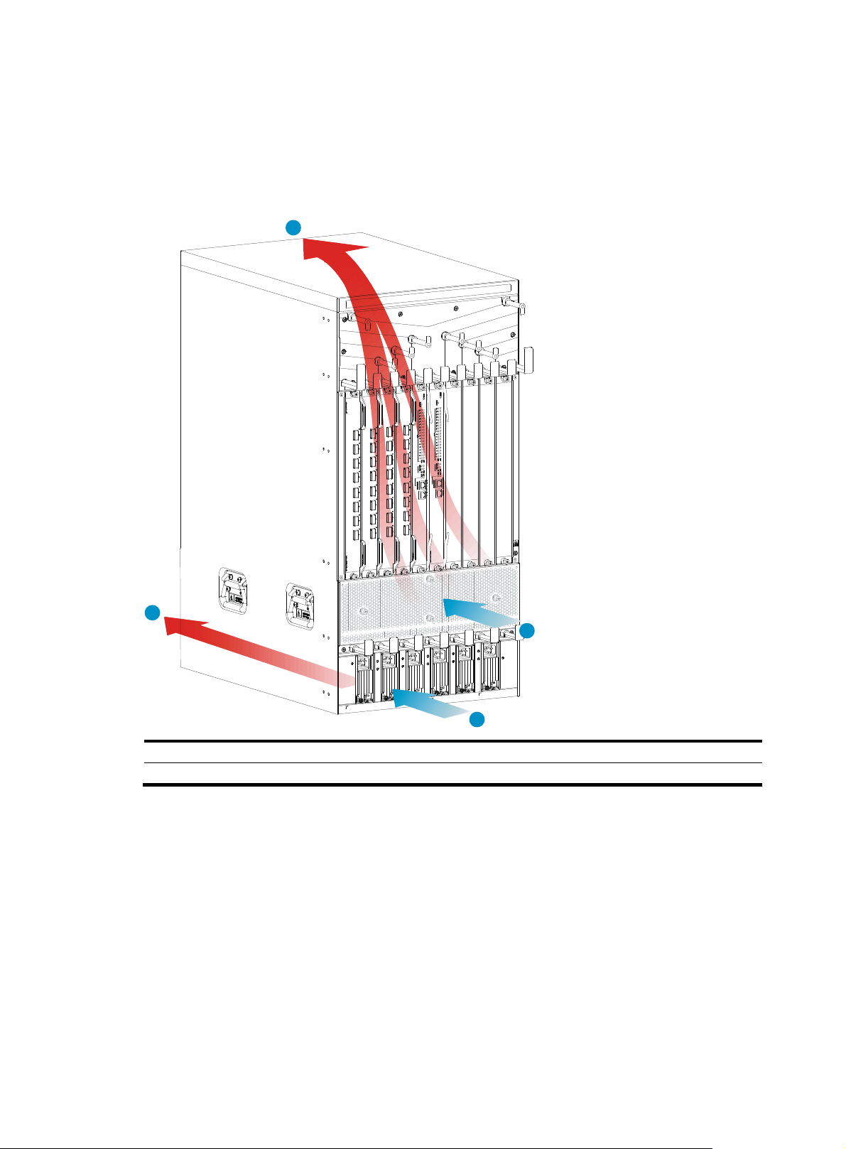
Figure 1 Airflow through the 11908-V Chassis
4
Space
For easy maintenance, follow these guidelines:
• Reserve at least 1 m (3.28 ft) of clearance between the rack and walls or other devices.
• The equipment room is at least 3 m (9.84 ft) high.
• Rack dimensions are sufficient for the chassis. For more information about chassis specifications,
2
3
1
(1) Power supply air intake vents (2) Power supply air exhaust vents
(3) Chassis air intake vents (4) Chassis air exhaust vents
see "Appendix A Chassis views and technical specifications."
5
Page 12

Installing the switch
IMPORTANT:
Keep the packages of the switch and the components for future use.
Confirming installation preparations
Before you install the switch, verify that:
• You have re ad "Preparing for installation" car
requirements.
• If you are rack-mounting the switch, verify that the following conditions are met:
{ A 19-inch rack is ready for use. For how to install a rack, see the rack installation guide.
{ The rack is sturdy and securely grounded.
{ No debris exists inside or around the rack.
{ Choose a correct rack mounting position for the switch. Make sure the heaviest device is placed
at the bottom of the rack.
{ The total height of the switches to be installed is no higher than the available installation height
of the rack, and enough clearance is reserved for cable routing.
• If you are mounting the switch on a workbench, make sure the workbench is sturdy and securely
grounded.
• The switch is ready for installation and has been carried to a place near the installation site and
convenient for moving.
efully and the installation site meets all the
Installing the switch in a 19-inch rack
Attaching slide rails and cage nuts to the rack
Installing slide rails
If the rack has slide rails, skip this section.
Before you attach slide rails to the rack, verify that the following conditions are met:
• The slide rails can support the weight of the switch. For the weights of the HP FlexFabric 1190 0
switches, see "Appendix A Chassis views and technical specifications."
HP recommen
(JC665A). For more information about the kit, see "Appendix B FRUs and compatibility matrixes."
• If y
ou install the switch in an enclosed cabinet, make sure the distance between the front rack posts
and the front door is at least 100 mm (3.94 in) for installing cable management brackets, and the
distance between the front rack posts and the rear door is at least 660 mm (25.98 in) for the chassis
with cards installed.
ds that you order the HP X421 A-Series Chassis Universal 4-Post Rack Mounting Kit
6
Page 13
g
• To ensure rack stability, install the slide rails to the lowest possible position when installing a single
switch on the rack. To install multiple switches on the rack, mount the heaviest switch at the bottom
of the rack.
• Identify the chassis and slide rail positions for the switch. For the height and other specifications, see
"Appendix A Chassis views and technical specifications."
Slide rail installation varies with rack type. This section uses the slide rails in the HP rack mounting kit
(JC665A) as an example.
To install a slide rail:
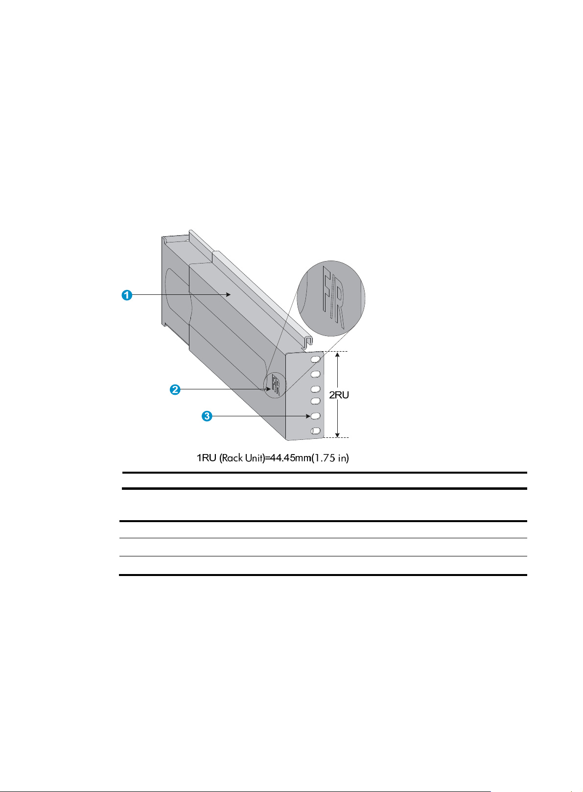
1. Read the signs on the slide rail (see Table 6) to avoid
Figure 2 Right slide rail
making a mistake.
(1) Guide rail (2) Sign (3) Installation hole
Table 6 Description of signs on the slide rails
Si
n Meaning Remarks
F/L Front end of the left slide rail Mount this end to the front left rack post.
F/R Front end of the right slide rail Mount this end to the front right rack post.
2. Mark the position on the rack for installing the slide rail:
a. Make sure the bottom edge of the slide rail aligns with the middle of the narrower metal area
between holes, as shown in Figure 3.
ach rack post r e quires six screws to at tach the slide rail. Mark the uppermost square hole and
b. E
lowermost square hole for installation.
c. Mark the square holes at the same height on the other three rack posts.
7
Page 14
NOTE:
One rack unit has three holes, the middle of which is an auxiliary installation hole, and the other two
are standard installation holes. You can distinguish them by the space between each two holes. The
space between a standard installation hole and an auxiliary installation hole is wider than that
between two adjacent standard installation holes.
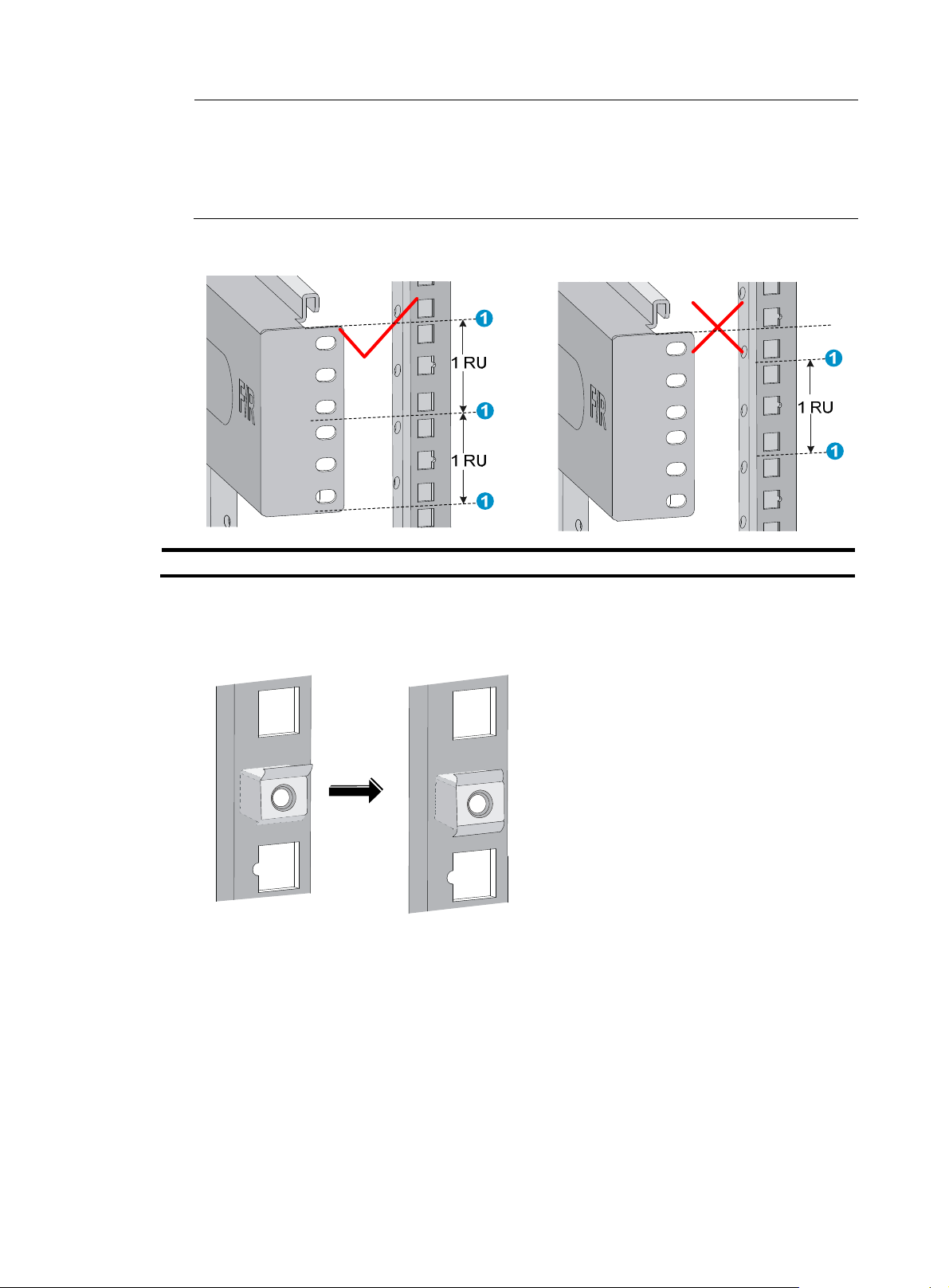
Figure 3 Locating the rack position for installing slide rails
(1) Middle of the narrower metal area between holes
3. Install six cage nuts in the square holes in each rack post, as shown in Figure 4.
Figure 4 Installing a cage nut
4. Align the installation holes on the front end of the slide rail with the cage nuts on the front rack post,
and attach them with screws, as shown in Figure 5.
8
Page 15
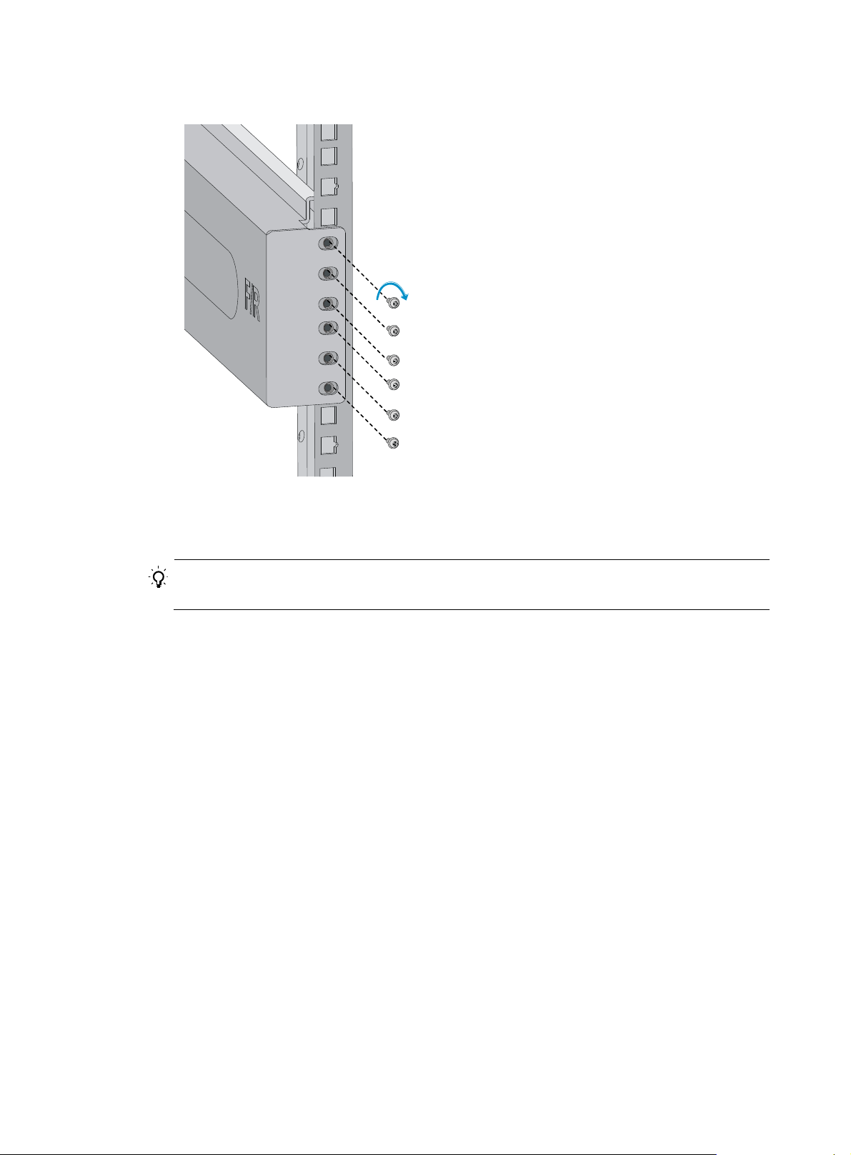
Figure 5 Attaching the slide rail to the cage nuts with screws
5. Keep the slide rail horizontally and adjust its length until the installation holes on the rear end of the
slide rail touch the cage nuts on the rear rack post. Then screw in screws and fasten.
TIP:
Install a screw in each mounting hole of the slide rail to ensure its weight bearing capacity.
6. Repeat steps 4 and 5 to install the other slide rail. Make sure the two slide rails are at the same
height so the device can be placed on them horizontally.
9
Page 16
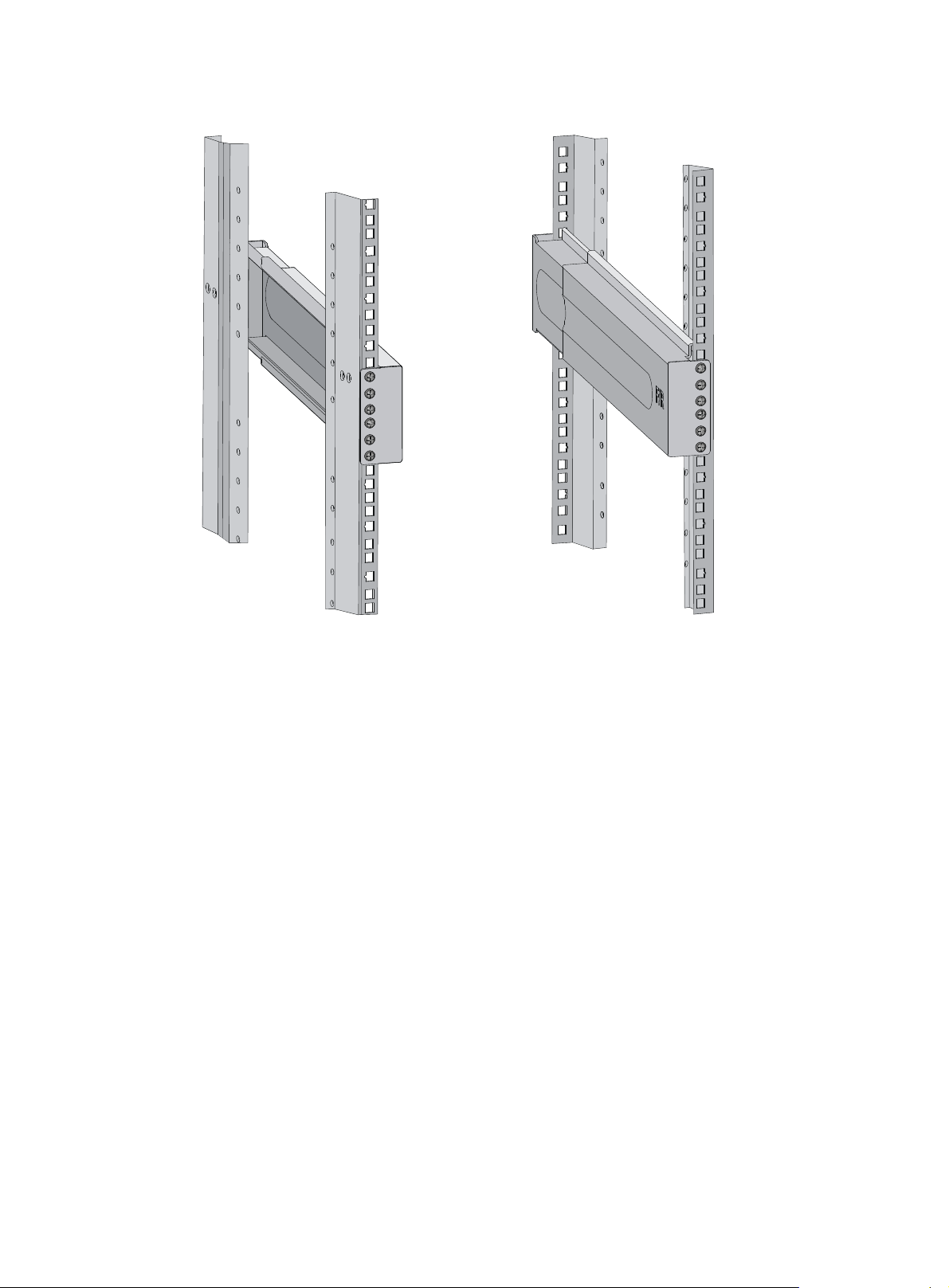
Figure 6 Installed slide rails
Installing cage nuts
To install cage nuts to the front square-holed brackets of the rack:
1. Determine the placement of the cage nuts, depending on holes in the mounting brackets and the
mounting position of the slide rails, as shown in Figure 7.
2. Install c
age nuts on the square holes on each rack post, as shown in Figure 4.
10
Page 17
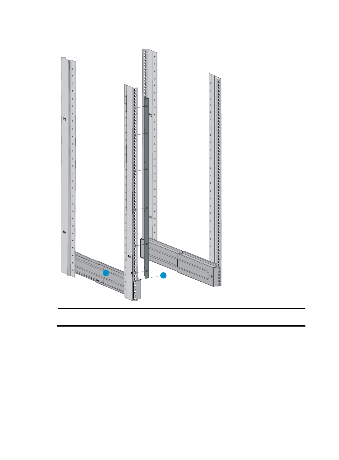
Figure 7 Installing cage nuts
2
1
(1) Place the bottom edge of the mounting bracket and the slide rail at the same level
(2) Locate the installation positions of cage nuts
Installing mounting brackets and cable management brackets
Before installing the switch to the rack, install the cable management brackets and mounting brackets
shipped with the switch. Cable management brackets (signal cable and power cable management
brackets) are used for cabling the switch, and mounting brackets are used for attaching the chassis to the
rack.
11
Page 18

Installing cable management brackets
The 11908-V has two cable management brackets: the cable management brackets are installed at the
upper part of the switch, and the power cable management brackets are installed at the lower part of the
switch. They are installed in the same way. For more information, see Figure 8.
T
o install a cable management bracket:
1. Unpack the cable management brackets.
2. Attach the cable management bracket to the chassis, and align the screws with the mounting holes
on the chassis, as shown in Figure 8.
3. Fasten the s
crews.
Figure 8 Attaching cable management brackets to a 11908-V
(1) Attach the cable management bracket to the chassis.
(2) Mounting holes for installing the cable management bracket.
(3) Screws for attaching the cable management bracket to the chassis.
(4) Cable management bracket (installed at the upper part of the chassis).
(5) Power cable management bracket (installed at the lower part of the chassis).
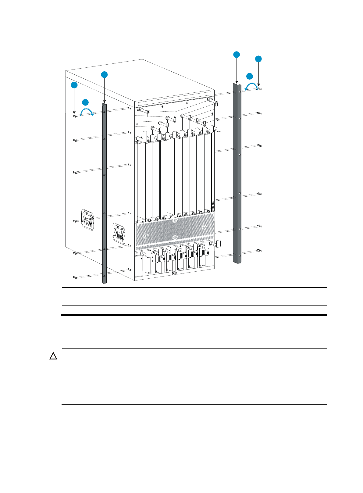
Attaching mounting brackets to the chassis
1. Identify the left mounting bracket (marked L) and the right mounting bracket (marked R) on the
inner surface of the mounting brackets.
2. Facing the chassis front, mount the left and right mounting brackets to the two sides of the chassis,
as shown in Figure 9.
12
Page 19
g
y
Figure 9 Installing the mounting brackets to a 11908-V
2
2
1
3
1
3
(1) Screws for attaching the mounting brackets to the chassis
(2) Mounting brackets
(3) Fasten the screws
Mounting the switch to the rack
CAUTION:
• Do not hold the handle of the fan tray, power supply, or the back cover of the chassis, or the air vents of
chassis. Any attempt to carry the switch with these parts may cause equipment dama
injury.
• After placing the switch on the slide rails, do not let go right away because this may tip the switch,
damage the switch, or cause bodily injury.
To mount the switch to the rack:
1. Move the chassis to face the rear of the chassis towards the front of the rack.
2. Use at least two people to lift the switch by using the handles or supporting the bottom of the
chassis until the bottom of the switch is a little higher than the slide rails on the rack.
e or even bodil
13
Page 20

HP recommends using a mechanical lift for moving your switch.
3. Place the switch on the slide rails and slide the switch along the slide rails until the mounting
brackets on the switch touch the front rack posts, as shown in callout 1 on Figure 10.
4. Attach the ch
Figure 10 Installing the chassis to the rack
(1) Slide the chassis into the rack
(2) Mounting brackets
(3) Screws for attaching the mounting brackets to the rack
assis to the rack with mounting screws.
NOTE:
If the mounting holes in the mounting brackets cannot align with the cage nuts on the rack, verify that the
bottom edge of the slide rail aligns with the middle of the narrower metal area between holes and that the
cage nuts are installed in the correct holes.
Mounting the switch on a workbench or floor
You can install the switch on a clean, sturdy workbench or on the floor.
Installation preparation
Before you mount the switch on a workbench or on the floor:
• Position the installation holes and drill holes. Make sure the holes are exact in diameter and depth
for the anchors to work correctly.
• Remove the shank and plug from a wall anchor, insert the spade-shaped wedges into the grooves
on the shank, put them into an installation hole, and hammer the shank into the ground. See Figure
11.
14
Page 21

g
g
w
IMPORTANT:
Before you hammer the shank to the workbench or floor, insert the spade-shaped wed
es into the grooves
on the shank. Otherwise, the wall anchor cannot be installed correctly.
Figure 11 Installing the shank to the plug
1
2
3
4
(1) Shank (2) Groove
Installation procedures
CAUTION:
Do not use the fan tray handles, power supply handles, chassis air vents, or handle of chassis back cover
for moving the chassis. These parts are not designed for weight support. Any attempt to carry the chassis
ith these parts might cause equipment damage or even bodily injury.
This task requires at least two people. HP recommends that you use a mechanical lift to move the chassis.
1. Hold the handles on the chassis or support the chassis bottom and steadily move the chassis to the
workbench or floor.
2. Gently put the chassis on the workbench or floor.
3. Attach the L-shaped brackets to the workbench or floor with wall anchors.
(3) Plu
(4) Spade-shaped wedge
15
Page 22

g
Figure 12 Attaching L-shaped brackets with wall anchors
(1) Fastening screw
(2) L-shaped bracket
(3) Wall anchor
Grounding the switch
CAUTION:
Before using the switch, connect the grounding cable changely to guarantee lightning protection and
anti-interference of the switch.
Grounding the switch with a grounding strip
CAUTION:
• Use the supplied grounding cable (yellow-green grounding cable).
• Connect the
main or lightning rod.
If a grounding strip is available at the installation site, connect the grounding cable through the
grounding strip.
rounding cable to the earthing system in the equipment room. Do not connect it to a fire
To connect the grounding cable:
1. Unpack the grounding cable.
The grounding cable provided with the switch is compliant with the NEBS standards.
16
Page 23

g
2. Remove the grounding screws from the grounding holes at the rear of the chassis, as shown in
callout 1 on Figure 13.
3. Fasten the gr
ounding screws, which are attached with the dual-hole terminals of the grounding
cable, into the grounding holes of the chassis.
4. Connect the ring terminal of the grounding cable to the grounding post of the grounding strip, and
fasten the grounding cable to the grounding strip with the hex nut.
Figure 13 Connecting the grounding cable to a grounding strip
(1) Grounding sign
(3) Grounding strip
(6) Hex nut
(2) Attach the grounding screws with dual-hole terminals to the grounding holes
(4) Grounding post
(5) Rin
terminal
Grounding the switch through the PE wire of an AC power supply
CAUTION:
Make sure the AC power supply uses a three-wire cable with a protection wire, and the PE wire of the AC
power supply is well grounded at the power distribution room or AC power supply transformer side. In
addition, make sure the PE connector on the switch is well connected to the PE wire of the AC power
supply.
If the switch is AC powered and no grounding strip is available at the installation site, you can ground
the switch through the PE wire of the AC power supply, as shown in Figure 14.
17
Page 24

Figure 14 Grounding the switch through the PE wire of the AC power supply
Grounding the switch through the RTN wire of a DC power supply
CAUTION:
Make sure the RTN wire is well grounded from the DC egress of the DC power cabinet.
If the switch is powered by a –48 VDC power supply and no grounding strip is available at the
installation site, you can ground the switch through the return (RTN) wire of the DC power supply, as
shown in Figure 15.
18
Page 25

Figure 15 Grounding the switch through the RTN wire of the DC power supply
DC power box
-48V strip
RTN strip
PGND strip
Ground
19
Page 26

Installing FRUs
There is no required order for installing FRUs. HP recommends that you connect power cords after
installing all required FRUs.
TIP:
Keep the chassis and component packages for future use.
Attaching an ESD wrist strap
The switch provides an ESD wrist strap. To minimize ESD damage to electronic components, wear the
ESD wrist strap and make sure it is well grounded when installing modules.
To use an ESD wrist strap:
1. Make sure the switch is well grounded. For how to ground your switch, see "Installing the switch."
2. Put on the wrist strap.
3. Tighten the wrist strap to keep good skin contact. Make sure the resistance reading between your
body and the ground is between 1 and 10 megohms.
4. As shown in Figure 16, insert the ESD wrist strap into th
it to the grounding screw of the chassis with an alligator clip.
e ESD port on the switch chassis, or attach
20
Page 27

Figure 16 Attaching an ESD-prevent wrist strap (on a 11908-V)
(1) ESD wrist strap port (having an ESD sign)
Installing a card
Unless otherwise stated, MPUs, LPUs, and switching fabric modules are collectively referred to as "cards"
in this document.
All cards of the HP FlexFabric 11900 switches are hot swappable.
After all cards are installed, you can verify the running status of a card by referring to the card status LED
(SLOT) on the MPU of the switch. If the RUN LED blinks, the card in the slot operates correctly. For more
information about card status LED (SLOT), see "Appendix C LEDs."
IMPORTANT:
• Before installing a card to the chassis, make sure the connectors on the card are not broken or blocked
to avoid damaging the backplane.
• To ensure good ventilation, install a blank filler panel over an empty MPU, LPU, or switching fabric
module slot. MPU slots use the same type of blank filler panels as LPU slots.
21
Page 28

Installing an MPU/LPU
The pink edged MPU slots and purple edged LPU slots of a 11908-V switch are located at the front panel.
The MPUs and LPUs are vertically oriented. When installing an MPU or LPU, make sure its PCB faces left.
To install an MPU or LPU:
1. Wear an ESD wrist strap, and make sure it makes good skin contact and is well grounded. For
more information, see "Attaching an ESD wrist strap."
2. As shown in
panel for future use.
Some card slots do not have a blank filler panel. The figures in this section are for illustration only.
3. As shown in callout 2 on Figure 17, hold the c
the card bottom with the other. Slide the card steadily into the slot along the guide rails.
4. When most part of the card is inserted in the slot, press the ejector levers on the card outward.
5. Push the card until the positioning pin on card touches the hole on the chassis.
6. As shown in callout 3 on Figure 17, pres
panel tightly and the card seats into the backplane
7. As shown in callout 4 on Figure 17, fasten the c
Figure 17 Installing a card
callout 1 on Figure 17, rem
ove the blank filler panel from the slot. Keep the blank filler
ard by the front panel with one hand and support
s the ejector levers inward until the ejector levers touch the
aptive screws on the card.
(1) Loosen the captive screws (2) Insert the card into the slot
(3) Press the ejector levers inward (4) Fasten the captive screws
Installing a switching fabric module
The gray edged switching fabric module slots of a 11908-V switch are located at the rear panel. The
switching fabric modules are horizontally oriented. When installing a switching fabric module, make sure
its PCB faces up.
To install a switching fabric module:
1. Wear an ESD wrist strap, and make sure it makes good skin contact and is well grounded. For
more information, see "Attaching an ESD wrist strap."
22
Page 29

2. Remove the filler panel (if any) from the target slot. Keep the filler panel for future use. See callout
1 on Figure 17.
3. Loo
sen the captive screws on the protection box on the switching fabric module for the 11908-V
switch, hold the ejector levers on the switching fabric module, pressing the buttons on the levers,
pull the ejector levers outward, and pull out the module. See Figure 18.
Keep the prot
ection box for future use.
4. Hold the switching fabric module by the front panel with one hand and support its bottom with the
other. Slide the switching fabric module steadily into the slot along the guide rails.
Do not touch the components on the PCB.
5. As shown in callout 1 in Figure 19, push t
he switching fabric module until the brakes on the ejector
levers touch the slot edges tightly.
6. As shown in callout 2 in Figure 19, press t
he ejector levers inward until the ejector levers touch the
panel tightly and the switching fabric module seats into the backplane.
7. As shown in callout 3 in Figure 19, fasten
the captive screws on the switching fabric module.
Figure 18 Removing the protection box
(1) Loosen the captive screws (2) Press down the buttons
(3) Pull the ejector levers outward (4) Pull out the switching fabric module
23
Page 30

Figure 19 Installing the switching fabric module
(1) Insert the card into the slot until the brakes touch the slot edges tightly
(2) Press the ejector levers inward
(3) Fasten the captive screws on the switching fabric module
Installing a power supply
CAUTION:
• Provide a circuit breaker for each power supply and make sure the circuit breaker is off before
installation.
• Do not install power supplies of different models on the same switch.
• To avoid power supply damage or bodily injury, support the bottom of a power supply instead of
holding its handle for power supply movement.
The switch uses N + 1 or N + N power redundancy and supports AC or DC power input.
The power supply slots are vertical on a 11908-V switch.
Strictly follow the order shown in Figure 20 to a
Figure 20 Power supply installation flow
void security hazards.
24
Page 31

AC and DC power supplies are installed in the same way. This section uses an AC power supply as an
example. For information about AC and DC power supplies, see HP FlexFabric 1190 0 250 0W AC Po we r
Supply User Guide and HP FlexFabric 11900 2400W DC Power Supply User Guide.
Some power supply slots do not have blank panels. The figures in this section are for illustration only.
To install the power supply:
1. Wear an ESD wrist strap and make sure it makes good skin contact and is well grounded. For
more information, see "Attaching an ESD wrist strap."
2. Use a Phillip
s screwdriver to loosen the captive screws on the blank filler panel (if any) to remove
the blank filler panel.
3. Unpack the power supply.
4. Follow the installation graph printed on the blank filler panel of the power supply to install the
power supply in a correct direction:
a. Grasp the handle of the module with one hand and support the module bottom with the other.
b. Push the power supply along the guide rails into the slot until it has firm contact with the slot,
as shown in callout 1 on Figure 21.
5. Press the han
6. As shown in callout 2 on Figure 21, us
dle inward until the handle seats into the slot.
e a Phillips screwdriver to fasten the captive screw on the
handle to attach the power supply.
25
Page 32

W
Figure 21 Installing an AC power supply
1
2
(1) Install the power supply to the chassis. (2) Fasten the captive screw.
Connecting the power cable
Connecting an AC power cable
ARNING!
Before connecting the power cable, make sure the circuit breaker on the power cable is switched off.
To connect an AC power cable:
1. Plug the power cable into the power receptacle of the power supply.
2. Use a cable tie to secure the power cable to the cable management bracket.
{ Figure 22 shows how to connect the power cable for a 119 0 8- V.
26
Page 33

W
3. Plug the other end of the power cable to the AC power receptacle of the power source and switch
on the circuit breaker.
4. Verify the power supply input status LED.
If the LED is on, the power cable is correctly connected. For description of power supply status LEDs,
see "Appendix C LEDs."
Figure 22 Securing the
power cable
Connecting a DC power cable
ARNING!
• Make sure each power cable has a separate circuit breaker.
• Before you connect the power cable, make sure the circuit breaker on the power cable is switched off.
• Make sure the circuit breaker at the power input end is off when you connect the DC power cable to the
terminals on the power source.
To connect a DC power cable:
1. Plug the power cable into the power receptacle of the power supply.
2. Fasten the screw to secure the power cable.
27
Page 34

Figure 23 Connecting the power cable
(1) Insert the power cable plug into the power supply. (2) Fasten the screw.
3. (Optional.) Use a cable tie to secure the power cable to the cable management bracket. For more
information, see Figure 22.
4. Connec
t one end of the blue DC power cable marked with –48V to the negative terminal (–48V)
on the power source and the RTN end of the black DC power cable to the positive terminal (RTN).
Installing a transceiver module (optional)
CAUTION:
• To avoid component damage, read this section carefully before installing a transceiver module.
• Do not remove the protection cover from a transceiver module before connecting an optical fiber.
• Remove the optical fiber, if any, from a transceiver module before installing it.
The transceiver modules available for the switch include SFP, SFP+, and QSFP+.
Installing an SFP+/SFP/QSFP+ module
1. Wear an ESD wrist strap and make sure it makes good skin contact and is well grounded. For
more information, see "Attaching an ESD wrist strap."
2. Unpack the m
3. Pivot the clasp of the module up. Holding the module, gently push the module into the slot until it
has firm contact with the slot (when the top and bottom spring tabs catch in the slot), as shown
in Figure 24.
odule. Do not touch the golden finger of the module.
{ For a QSFP+ module that uses a plastic pull latch, skip this step. QSFP+ modules use either a
metal or plastic pull latch. They are installed in the same way except that you must pivot the
clasp up for the module that uses a metal pull latch.
{ For an SFP+ module, press the module down against the upward force of the bottom spring tab
so you can push the module straight into the port.
{ If you cannot hold the module by its two sides because of high module density, press the module
on its head end to push it in.
28
Page 35

4. Connect the fiber to the module. For the installation procedure, "Connecting your switch to the
network."
Figure 24 Installing an SFP+/SFP/QSF
P+ module
Connecting an SFP+/QSFP+/QSFP+ to SFP+ cable
Use SFP+ cables to connect SFP+ ports, QSFP+ cables to connect QSFP+ ports, and QSFP+ to SFP+
cables to connect QSFP+ and SFP+ ports. All these cables are hot swappable.
To connect an SFP+, QSFP+, or QSFP+ to SFP+ cable:
1. Wear an ESD wrist strap and make sure it makes good skin contact and is well grounded. For
more information, see "Attaching an ESD wrist strap."
2. Unpac
3. Plug the cable connector into the port. Make sure the cable connector is the right side up.
k the cable.
The bend radius of the cable must be at least eight times the cable diameter.
29
Page 36

Setting up an IRF fabric
You can use HP IRF technology to connect and virtualize the switches into a large virtual switch called an
"IRF fabric" for flattened network topology, high availability, scalability, and manageability. For more
information about IRF, see HP FlexFabric 11900 Switch Series IRF Configuration Guide.
IRF fabric setup flowchart
The setup flow is shown in Figure 25. For the actual procedure, see HP FlexFabric 11900 Switch Series IRF
Configuration Guide for the software release you are using.
Figure 25 IRF fabric setup flowchart
To set up an IRF fabric:
30
Page 37

Step Description
Plan the installation site and IRF fabric setup parameters:
• Planning IRF fabric size and the installation site
1. Plan IRF fabric setup.
• Identifying the master switch and planning IRF member IDs
• Planning IRF topology and connections
• Identifying physical IRF ports on the member switches
2. Install IRF member switches.
3. Power on the switches.
4. Configure basic IRF settings on
each switch in standalone
mode.
5. Connect the physical IRF ports.
6. Enable IRF mode.
7. Verify the IRF settings.
8. Configure other settings in IRF
mode.
See "Installing the switch."
N/A
See HP FlexFabric 11900 Switch Series IRF Configuration Guide.
Connect physical IRF ports on switches.
See HP FlexFabric 11900 Switch Series IRF Configuration Guide.
Log in to the IRF fabric at any member switch and verify that you can
configure all member switches as if they were one node.
See HP FlexFabric 11900 Switch Series IRF Configuration Guide.
Planning IRF fabric setup
This section describes issues that an IRF fabric setup plan must cover.
Planning IRF fabric size and the installation site
Plan IRF fabric size and the installation site, using the following procedure:
1. Use HP FlexFabric 11900 Switch Series IRF Configuration Guide as a reference to identify the
number of member switches that your system software version supports for an IRF fabric.
All member switches must use the same system software version.
2. Select LPUs that can provide 10-GE/40-GE ports.
The switches require 10-GE/40-GE ports for IRF connection. For more information about LPUs, see
"Appendix B FRUs and compatibility matrixes."
3. Select SFP+/QSFP+ transceiver modules and fibers for long-haul IRF connection, or select
SFP+/QSFP+/QSFP+ to SFP+ cables for short-haul IRF connection. Select 10Gbase-T twisted-pair
cables for short-haul IRF connection.
For more information about transceiver modules and cables, see "Appendix B FRUs and
compatibility matrixes."
4. Plan the installation site.
Identifying the master switch and planning IRF member IDs
Determine which switch you want to use as the master for managing all member switches in the IRF
fabric.
31
Page 38

An IRF fabric has only one master switch. You configure and manage all member switches in the IRF
fabric at the CLI of the master. IRF member switches will automatically elect a master. You can affect the
election result by assigning a high member priority to the intended master switch. For more information
about master election, see HP FlexFabric 11900 Switch Series IRF Configuration Guide.
Prepare an IRF member ID assignment scheme. An IRF fabric uses member IDs to uniquely identify and
manage its members, and you must assign each IRF member switch a unique member ID.
Planning IRF topology and connections
Connect the IRF member switches through IRF ports, the logical interfaces for the connections between
IRF member switches. Each IRF member switch has two IRF ports: IRF-port 1 and IRF-port 2. To use an IRF
port, you must bind at least one physical port to it.
When connecting two neighboring IRF member switches, you must connect the physical ports of IRF-port
1 on one switch to the physical ports of IRF-port 2 on the other switch.
A two-member IRF fabric must use the daisy chain topology.
If the system software version you are using supports more than two IRF members, you can create an IRF
fabric that comprises more than two members in daisy chain topology or more reliable ring topology. In
ring topology, the failure of one IRF link does not cause the IRF fabric to split as in daisy chain topology.
Instead, the IRF fabric changes to a daisy chain topology without interrupting network services.
Identifying physical IRF ports on the member switches
Identify the physical IRF ports on the member switches according to your topology and connection
scheme.
On the switch, only 10-GE/40-GE ports can be used for IRF connection.
The switch supports multi-card link aggregation for IRF ports. You can bind up to eight physical ports to
one IRF port.
Installing IRF member switches
Step Reference
1. Prepare the installation site.
2. Rack mount the IRF member switches.
3. Install modules on IRF member switches.
Preparing for installation
Installing the switch
Installing FRUs
Configuring basic IRF settings
After you install the IRF member switches, power on the switches, and log in to each IRF member switch
(see "Connecting your switch to the network") t
port bindings.
Follow these guidelines when you configure the switches:
o configure their member IDs, member priorities, and IRF
32
Page 39

• First configure the member IDs, member priorities, and IRF port bindings for the IRF member
switches, save the configuration, connect the member switches, and change the operating mode of
the switches to IRF mode.
• Assign the master switch higher member priority than any other switch.
• Bind physical ports to IRF-port 1 on one switch and to IRF-port 2 on the other switch.
• Execute the display irf configuration command to verify the basic IRF settings.
For more information about configuring basic IRF settings, see HP FlexFabric 11900 Switch Series IRF
Configuration Guide.
Connecting the physical IRF ports
Follow these guidelines when selecting transceiver modules and cables:
• Use SFP+ transceiver modules and fibers for long-distance connection, or use SFP+ cables to
connect SFP+ ports for short-distance connection.
• When connecting SFP+ ports, connect the transmit port of an SFP+ transceiver module at one end
to the receive port of an SFP+ transceiver module at the other end.
• Use QSFP+ transceiver modules and fibers for long-distance connection, or use QSFP+ cables to
connect QSFP+ ports for short-distance connection.
• Use twisted-pair cables to connect 10Gbase-T ports.
• The transceiver modules at the two ends of an IRF link must be the same type.
For more information about installing transceiver modules, see "Installing FRUs." F
about connecting fibers, see "Connecting your switch to the network."
Figure 26 Connecting two IRF member switches
or more information
33
Page 40

g
P
Verifying the IRF fabric configuration
After you finish configuring basic IRF settings and connecting IRF ports, verify the basic functionality of
the IRF fabric, as follows:
1. Log in to the IRF fabric through the console port of any member switch.
2. Create a Layer 3 interface, assign it an IP address, and make sure the IRF fabric and the remote
network management station can reach each other.
3. Use Telnet or SNMP to access the IRF fabric from the network management station. (See HP
FlexFabric 11900 Switch Series Fundamentals Configuration Guide.)
4. Verify that you can manage all member switches as if they were one node.
5. Display the running status of the IRF fabric by using the commands in Table 7.
Table 7 Displaying and maintaining IRF configuration and runni
Task Command
Display information about the IRF fabric. display irf
Display topology information about the IRF fabric. display irf topology
NOTE:
To avoid IP address collision and network problems, confi
presence of multiple identical IRF fabrics and handle collisions. For more information about MAD, see
FlexFabric 11900 Switch Series IRF Configuration Guide.
ng status
ure at least one MAD mechanism to detect the
H
34
Page 41

Connecting your switch to the network
This chapter describes how to connect your switch to a network.
The first time you access the switch you must log in through the console port. On the switch, you can
configure Telnet or SSH for remote access through Ethernet ports. You manage console login users at
AUX user lines, and manage Telnet and SSH users at VTY user lines. For more information about login
methods and user lines, see HP FlexFabric 11900 Switch Series Fundamentals Configuration Guide.
NOTE:
• The switch with one MPU supports one AUX user and the switch with two MPUs supports up to two
concurrent AUX users. The total number of AUX users that an IRF fabric supports equals the number of
MPUs in the IRF fabric.
• An HP FlexFabric 11900 switch supports up to 16 concurrent VTY users.
Accessing the switch for the first time
The first time you access the switch you must use a console cable to connect a console terminal, for
example, a PC, to the console port on the switch.
Setting up the configuration environment
To connect a terminal (for example, a PC) to the switch:
1. Plug the DB-9 female connector of the console cable to the serial port of the PC.
2. Plug the RJ-45 connector of the console cable to the console port of the switch.
3. Power on the PC.
NOTE:
• Identify the mark on the console port and make sure you are connecting to the correct port.
• The serial ports on PCs do not support hot swapping. If the switch has been powered on, connect the
console cable to the PC before connecting to the switch, and when you disconnect the cable, first
disconnect from the switch.
35
Page 42

Figure 27 Connecting a console port to a terminal
Setting terminal parameters
To configure and manage the switch, you must run a terminal emulator program on the console terminal.
If your PC runs Windows 2003 Server, add the HyperTerminal component before performing the
following steps to log in to and manage the switch. If your PC runs Windows 2008 server, Windows 7,
Windows Vista, or any other operating system, prepare third-party terminal control software, and follow
the software user guide or help to configure the terminal.
The following are the required terminal settings:
• Bits per second—9,600
• Data bits—8
• Parity—None
• Stop bits—1
• Flow control—None
• Emulation—VT100
To set terminal parameters, for example, on a Windows XP HyperTerminal:
1. Select Start > All Programs > Accessories > Communications > HyperTerminal.
The Connection Description dialog box appears.
2. Enter the name of the new connection in the Name field and click OK.
36
Page 43

Figure 28 Connection description
3. Select the serial port to be used from the Connect using list, and click OK.
Figure 29 Setting the serial port used by the HyperTerminal connection
4. Set Bits per second to 9600, Data bits to 8, Parity to None, Stop bits to 1, and Flow control to None,
and click OK.
37
Page 44

Figure 30 Setting the serial port parameters
5. Select File > Properties in the HyperTerminal window.
Figure 31 HyperTerminal window
6. On the Settings tab, set the emulation to VT100 and click OK.
38
Page 45

Figure 32 Setting terminal emulation in Switch Properties dialog box
Powering on the switch
Before powering on the switch, confirm the following:
• You know where the emergency power-off switch for the equipment room is located.
• The switch has been securely mounted.
• All the cards have been correctly installed.
• The unused slots have been installed with blank filler panels.
• All the network cables, fibers, power cables, and grounding cables have been correctly connected.
• The input power voltage meets the requirement of the switch.
• The console cable is correctly connected, the terminal or PC used for configuration has started, and
the configuration parameters have been set.
To power on the switch:
Turn on the power source of the switch to power on the switch.
The following is sample output you can see on the terminal:
System is starting...
Press Ctrl+D to access BASIC-BOOTWARE MENU...
Press Ctrl+T to start memory test
Press Ctrl+V to start heavy memory test
Booting Normal Extended BootWare....
39
Page 46

The Extended BootWare is self-decompressing......Done.
****************************************************************************
* *
* BootWare, Version 1.08 *
* *
****************************************************************************
Compiled Date : Jan 7 2013
CPU Type : XLP316
CPU Clock Speed : 1200MHz
Memory Type : DDR3 SDRAM
Memory Size : 8192MB
Memory Speed : 667MHz
BootWare Size : 1536KB
Flash Size : 500MB
BASIC CPLD Version : 1.0
EXTENDED CPLD Version: 1.0
PCB Version : Ver.A
BootWare Validating...
Press Ctrl+B to access EXTENDED-BOOTWARE MENU...
normal boot app
Loading the main image files...
Loading file flash:/11900-CMW710-SYSTEM-A2102.bin.......................
............................................................................
............................................................................
............................................................................
............................................................................
............................................................................
...................................................Done.
Loading file flash:/11900-CMW710-BOOT-A2102.bin.........................
............................................................................
............................................Done.
Image file flash:/11900-CMW710-BOOT-A2102.bin is self-decompressing.....
............................................................................
...............Done.
System image is starting...
User interface aux4/0 is available.
Press ENTER to get started.
Press Enter at the prompt. When the prompt <Sysname> appears, you can configure the switch.
After powering on the switch, verify the following items:
• The cooling system is operating, and you can hear fan rotating noise and feel air being blown out.
40
Page 47

g
• The system status LEDs on the MPUs show that the system is operating correctly. For more
information about LED behaviors, see "Appendix C LEDs."
Configuring the switch
By default, the switch does not authenticate the console login user at an AUX interface. To increase
system security and enable remote management:
• Configure remote access services, for example, Telnet or SSH.
• Configure authentication on each user interface, including the AUX interfaces.
Configuring authentication on a user interface
You can configure authentication on a user interface to control access to the switch.
Table 8 de
scribes the Telnet login authentication methods available for a VTY user line.
Table 8 Telnet login authentication methods
Authentication
method
None
Password
Username and
password
Feature Application scenarios
Easy to configure, allows any user to Telnet to
your switch, and lowest in security
Easy to configure, secure, and flat user
management
Complex to configure, secure, and
hierarchical user management
For more information about login methods, see HP FlexFabric 11900 Switch Series Fundamentals
Configuration Guide.
Configuring the basic access function
The switch without any configuration can perform basic data forwarding immediately after it is plugged
into a network. To implement more forwarding features, configure the basic network settings in Table 9
on the s
witch.
Lab environments and extremely secure
network environments
Environments that do not need granular
privilege management
Environments where multiple operators
cooperate to manage the switch
Table 9 Basic network settings
Settin
Description
IP address Enables remote switch management, for example, by using Telnet.
Static routes Implement static routing.
VLANs Divide the LAN into multiple VLANs for data security.
MSTP Avoids loops in a dual-homed network.
41
Page 48

Configuration example
Configuring Telnet service
# Enter system view.
<Sysname> system-view
# Enable the Telnet server.
[Sysname] telnet server enable
# Enter the view of user line VTY 0.
[Sysname] user-interface vty 0
# Enable password authentication on the user line.
[Sysname-ui-vty0] authentication-mode password
# Set the password to hello in plaintext.
[Sysname-ui-vty0] set authentication password simple hello
# Assign user role network-admin through the user line VTY 0.
[Sysname-ui-vty0] user-role network-admin
[Sysname-ui-vty0] quit
Configuring the basic network settings
• Configure IP addresses
# Create VLAN-interface 1.
[Sysname] interface vlan-interface 1
# Assign an IP address, for example, 192.168.0.1, to VLAN-interface 1.
[Sysname-Vlan-interface1] ip address 192.168.0.1 24
[Sysname-Vlan-interface1] quit
• Configure static routes
# Configure a static route, with the destination IP address 172.16.1.0 and the next hop IP address
192.168.0.2.
[Sysname] ip route-static 172.16.1.0 255.255.255.0 192.168.0.2
• Configure VLANs
# Create VLAN 10 and enter its view.
[Sysname] vlan 10
[Sysname-vlan10]
# Assign port Ten-GigabitEthernet 1/0/1 to VLAN 10.
[Sysname-vlan10] port ten-gigabitethernet 1/0/1
[Sysname-vlan10] quit
• Configure MSTP
# Create an MST region named example, map VLAN 10 to instance 1, and set the MSTP revision
level to 0.
[Sysname] stp region-configuration
[Sysname-mst-region] region-name example
[Sysname-mst-region] instance 1 vlan 10
[Sysname-mst-region] revision-level 0
# Activate the MST region configuration.
[Sysname-mst-region] active region-configuration
42
Page 49

[Sysname-mst-region] quit
# Configure the switch as the primary root bridge of instance 1.
[Sysname] stp instance 1 root primary
# Enable MSTP globally.
[Sysname] stp global enable
For more information about these features, see HP FlexFabric 11900 Switch Series Configuration Guides.
Verifying the network configuration
To verify the software version and network configuration, execute display commands in any view.
Task Command
Display the name, model, and system software version of the switch. display version
Display the current configuration of the switch. display current-configuration
Display the interface status and configuration. display interface brief
Display the IP configuration of Layer 3 interfaces. display ip interface brief
Display information about active routes in the routing table. display ip routing-table
Display VLAN settings. display vlan
Display the spanning tree status and statistics. display stp brief
Connecting the switch to the network
Before you connect the switch to the network, verify that all its basic settings are correct.
Connecting your switch to the network through twisted pair cables
You can use category 6A or category 7 twisted pair cables to connect the 10GBase-T ports on your
switch to the network. These ports use RJ-45 connectors and support MDI/MDI-X auto-sensing. For more
information about twisted pair cables, see "Appendix D Cables."
To connect a 10GBase-T port to a peer device:
1. Plug one end of a twisted pair cable into the port.
2. Plug the other end of the twisted pair cable into the RJ-45 Ethernet port of the peer device.
3. Verify the port LEDs for incorrect connection.
For more information about the LED status, see "Appendix C LEDs."
43
Page 50

W
Connecting your switch to the network through optical fibers
ARNING!
To avoid injury to your eyes, do not stare at the optical fiber interfaces and optical fiber connectors when
connecting optical fibers.
You can install a transceiver module (see "Installing FRUs") in a fiber port and use optical fibers to
connect the port to the network. For more information about optical fibers, see "Appendix D Cables."
To connect a fiber port to a peer device through optical fibers:
1. Install a transceiver module into the port.
2. Remove the dust cover of the optical fiber connector, and clean the end of the optical fiber.
3. Remove the dust plug of the transceiver module, plug one end of the optical fiber into the
transceiver module, and plug the other end into the transceiver module in the peer device.
{ For how to connect an LC connector, see Figure 33.
{ For how to connect an MPO connector, see Figure 34.
4. Examine the port LEDs for incorrect connection.
For more information about the LED status, see "Appendix C LEDs."
NOTE:
For a QSFP+ module, you do not need to differentiate between the Tx and Rx ports. For other types of
transceiver modules, the Tx port on one end must connect to the RX port on the other end.
Figure 33 Using LC optical fiber connectors to connect transceiver modules
Figure 34 Using an MPO optical fiber connector to connect a QSFP+ module
MPO plug
QSFP+ module
44
Page 51

Testing connectivity
After you plug the switch into the network, use the ping or tracert command to test the network
connectivity. For more information about these commands, see HP FlexFabric 11900 Switch Series
Command References.
45
Page 52

Troubleshooting
This chapter describes how to troubleshoot your switch.
TIP:
• Clean your switch periodically because the noncompliant operating environments of switches may
cause switch failures.
• Verify the installation environments against the requirements in "Preparing for installation." M
the switch operates in a compliant environment.
• Periodically perform the power-on test for the spare switches.
Troubleshooting methods
If your switch fails, you can use the following methods to troubleshoot the switch:
• At the CLI, you can use the related commands to display the hardware information and locate the
hardware failures.
• The MPU provides the LEDs for the fans and cards. You can locate the failures according to the LED
status on the MPU. For more information about the LED status on the MPU, see "Appendix C LEDs."
• The MPU or LPU of the switch provides the port status LEDs, with which you can detect port failures.
For more information about the LED status on the LPU, see "Appendix C LEDs."
f you cannot locate failures by following the guidelines in this chapter, contact HP Support for help. For
I
more information, see "Support and other resources."
Configuration terminal problems
ake sure
If the configuration environment setup is correct, the configuration terminal displays boot information
when the switch is powered on. If the setup is incorrect, the configuration terminal displays garbled text
or does not display anything.
No terminal display
If the configuration terminal displays nothing when the switch is powered on, verify the following items:
• The power supply system is operating correctly.
• The MPU is operating correctly.
• The console cable has been connected to the console port of the MPU.
If no problem is found, examine the console cable for the following problems:
• The console cable is connected to an incorrect serial interface (the serial interface in use is not the
one set on the terminal). To solve this problem, select the correct serial interface.
• The console cable is broken. To solve this problem, replace the console cable.
46
Page 53

Garbled terminal display
If terminal display is garbled, verify that the following settings are configured for the terminal, for
example, HyperTerminal:
• Baud rate—9,600
• Data bits—8
• Parity—none
• Stop bits—1
• Flow control—none
When you modify the settings for the console port of the switch, configure the same settings for the
console terminal.
Troubleshooting the switch during the operation
Use display commands to examine the configuration for configuration errors or to examine statistics for
exceptions.
If any configuration errors are found, re-configure the switch or restore the factory-default settings.
Power supply system failure
If the switch is operating correctly, the LEDs on the power supply (AC LED and DC LED) are green. For
more information, see "Appendix C LEDs."
After a power supply is powered off, it is normal that the power LEDs stay ON for several seconds.
If the power LEDs are off or not green, examine the power supply for an exception, as follows:
1. If the DC LED is orange, the power supply has transitioned to the over-temperature protection state.
Examine the cooling system for inadequate ventilation, and make sure every empty slot has been
covered by a blank filler panel.
2. If the DC LED is red, the power supply has transitioned to a self-protection state because of a power
supply problem. Examine the power supply for output short circuit, output over-current, output
over-voltage, input under-voltage, or remote disconnection.
The DC LED also turns red if the input of the power supply is disconnected while any other power
supply is operating correctly. In this case, connect the input or keep the input disconnected as
needed.
3. Examine the power cable connections. If a power cable is loose, re-plug the power cable. If a
power cable is broken, replace it.
4. Examine the power supply installation. If the power supply is not fully seated, re-install the power
supply to make sure it has a close contact with the backplane of the switch.
5. Examine the power supply system. Make sure the power supply system works correctly and
provides a normal voltage.
6. If the switch has empty power supply slots, unplug the power supply, plug the power supply into
an empty power supply slot after all LEDs on the power supply are off, and verify that the power
supply can operate correctly.
47
Page 54

7. Plug a new power supply of the same model into the same slot, and connect it to the same power
input end. If the new power supply can operate correctly, the old power supply has failed. You
must replace the old power supply.
Fan failure
Both the MPU and the fan tray provide the fan tray LEDs, including an OK LED and a FAIL LED. When the
fan tray operates correctly, the OK LED is on, and the FAIL LED is off.
If the OK LED is off or the FAIL LED is on, the fan tray has failed. To troubleshoot the fan tray:
1. If both LEDs are off, verify that the power supplies are operating correctly. For more information,
see "Power supply system failure."
2. Verify that the air intakes a
clean them to keep good ventilation.
3. Verify that the fan tray is fully seated. You can unplug the fan tray, plug it again, and then fasten
the screws.
4. Verify that the empty LPU slots and power supply slots are installed with blank filler panels. If not,
install blank filler panels for them to guarantee good ventilation.
5. If the failure persists, contact HP Support for help.
MPU failure
The status LEDs on the MPU show the status of a card in the corresponding slot. According to the slot
number of an MPU, you can verify the corresponding LEDs for the MPU.
When the MPU operates correctly, the RUN LED flashes and the ALM LED is off. When the RUN LED is
off, the MPU fails. To troubleshoot the MPU:
1. Verify that the power supply operates correctly. For more information, see "Power supply system
failur
e."
2. Verify that the MPU is fully seated. You can unplug the MPU, plug it again, and make sure the MPU
is fully seated.
3. Press the RESET button of the MPU to reset the MPU. After the MPU is reset, verify whether the
corresponding RUN LED is on.
nd exhaust vents of the chassis are not blocked. If they are blocked,
4. If the switch has an empty MPU slot, plug the MPU into the slot to test the MPU.
5. If the failure persists, contact HP Support for help.
LPU and switching fabric module failure
Use the card status LEDs on the MPU to identify the failure of the LPU or switching fabric module in a
particular slot.
If a card is operating correctly, the RUN LED flashes and the ALM LED is off. When the RUN LED is off,
the card fails. To troubleshoot the card:
1. Verify that the MPU is operating correctly. For more information, see "MPU failure."
2. Verify that the software version is compatible with the card. If not, upgrade the soft
compatible version.
48
ware to a
Page 55

A
g
g
3. Calculate the total power consumption, and make sure your power supplies can provide enough
power. For more information, see "Appendix B FRUs and compatibility matrixes."
4. Verify that the card is fully seated. You can unplug the card, plug it again, and press the ejector
levers inward until the ejector levers touch the panel tightly. For a switching fabric module, you
must verify that the ejector levers touch the panel tightly and the switching fabric module seats into
the backplane.
5. If the switch has empty card slots, plug the card into an empty card slot, and verify that the card
can operate correctly.
6. If the failure persists, contact HP Support for help.
Interface failure
The interfaces provided by MPUs and LPUs all have corresponding LEDs. When an interface connected
to the network operates correctly, the corresponding LED is on.
NOTE:
management Ethernet interface has two LEDs, LINK and ACT. The LED in this section for such an
interface refers to the LINK LED. Each interface of any other type has only one LED.
If the LED of an interface connected to the network is off, the interface or the connecting cable may fail.
To troubleshoot the interface:
1. Make sure the MPU or LPU where the interface resides is operating correctly. For more information,
see "MPU failure" or "LPU and switching fabric module failure."
2. Examine the cable connection of the interface. For how to correctly connect the cable to an
Ethernet interface with an RJ-45 connector or an optical interface, see Connecting your switch to
the network."
3. Verify that the cable is in good condition. Use the cable to connect two interfaces of the same type
that operate correctly. If the LEDs of the two interfaces are on, the cable is normal. Otherwise, the
cable fails. Use a compliant cable to connect the interface. For more information about the
compliant cables, see "Appendix D Cables."
4. If the interface uses a transceiver module, make sure the interface type is compatible with the
transceiver and that the transceiver is compatible with the cable. For more information, see
"Appendix B FRUs and compatibility matrixes."
5. If the interface uses a transceiver module, make sure the current transceiver works correctly by
replacing a normal transceiver.
NOTE:
• If a port is brought down by the shutdown command, use the undo shutdown command to brin
interface.
up the
• After an interface fails, if the switch has an idle interface of the same type, you can plu
the idle interface.
the cable into
6. Verify that the speed and duplex settings of the interfaces of a link are the same. Make sure two
interfaces can work together.
7. If the failure persists, contact HP Support for help.
49
Page 56

W
W
t
g
Replacement procedures
CAUTION:
hen replacing FRUs while the switch is running, be aware of electrical safety hazards.
The switch uses a modular, hot-swappable architecture, and supports FRUs. You can replace any of FRUs
when the switch is running.
Replacing a power supply
ARNING!
• Follow the procedures shown in Figure 35 an
bodily injury.
• The replacement power supply must be an HP FlexFabric 11900 2500W AC Power Supply (JG616A) or
HP FlexFabric 11900 2400W DC Power Supply (JG617A).
d Figure 36 to replace a power supply to avoid device or
• Power supplies on an HP FlexFabric 11900 switch must be the same model. The model of the replacemen
power supply must be the same as the model of the power supplies that are operating correctly. If not,
disconnect the power supply and remove all power supplies before replacement.
• Add a circuit breaker to the power line for each power supply. Before replacin
its circuit breaker.
• The power supply may be of high temperature. Remove it with caution.
• To install the removed power supply to the chassis again, install it after the status LED on it is off.
• After removing the power supply, if you do not install a new power supply, install a blank filler panel.
Figure 35 Power supply removal flow
Figure 36 Power supply installation flow
To replace a power supply:
1. Prepare an antistatic mat to place the removed power supply.
a power supply, turn off
2. Wear an ESD wrist strap and make sure it makes good skin contact and is well grounded. For
more information, see "Installing FRUs."
3. Switc
4. Remove the cable ties from the power cable, and remove the power cable from the power supply.
5. Use a Phillips screwdriver to loosen the captive screw on the power supply, and then grasp the
h off the circuit breaker on the power supply.
captive screw between your thumb and index finger to carefully pull out the handle on the power
supply, as shown in callout 1 on Figure 37.
50
Page 57

6. Holding the power supply handle with one hand and, supporting the bottom of the power supply
with the other, gently pull the power supply out, as shown in callout 2 on Figure 37.
7. Put the rem
8. Install a new power supply. For the installation procedures, see "Installing FRUs."
Figure 37 Removing the power suppl
oved power supply on the antistatic mat.
y
1
2
(1) Loosen the captive screw (2) Pull the power supply out
Replacing a card
The replacement procedures of the cards on the HP FlexFabric 11900 switches are similar. Before you
replace a card, remove all its cables.
If no new card is to be installed, install a blank filler panel to ensure adequate ventilation and dust
prevention.
Replacing an MPU or LPU
The MPUs and the LPUs of 11908-V are installed in vertical slots, and the replacement procedures are the
same.
51
Page 58

1. Prepare an antistatic mat to place the removed card.
2. Wear an ESD wrist strap and make sure it makes good skin contact and is well grounded. For
more information, see "Installing FRUs."
emove all cables from the card.
3. R
4. Use a Phillips screwdriver to remove the captive screw on the card, as shown in callout 1 on Figure
38.
5. Move the
ejector levers outwards to separate the card from the backplane, as shown in callout 2
on Figure 38.
6. Use on
e hand to slowly move the card outwards. Supporting the bottom of the card with the other
hand, pull the card out of the slot along slide rails, as shown in callout 3 on Figure 38.
7. Put the rem
oved card on the antistatic mat.
8. Install a new card. For the installation procedures, see "Installing FRUs."
Figure 38 Replacing a card
2
3
1
2
(1) Loosen the captive screw. (2) Move the ejector levers outwards.
(3) Take out the card.
Replacing a switching fabric module
1. Prepare an antistatic mat to place the removed switching fabric module.
2. Wear an ESD wrist strap and make sure it makes good skin contact and is well grounded. For
more information, see "Installing FRUs."
3. Use a Phillips scr
in callout 1 on Figure 39.
4. Press the butt
switching fabric module from the backplane, as shown in callout 2 on Figure 39.
5. Slowly move the switc
module, pull the switching fabric module out of the slot along the slide rails, as shown in Figure 40.
ewdriver to loosen the captive screws on the switching fabric module, as shown
ons on the ejector levers and then move the ejector levers outward to separate the
hing fabric module outward. Holding both sides of the switching fabric
52
Page 59

6. Put the removed switching fabric module on the antistatic mat.
7. Install a new switching fabric module. For the installation procedures, see "Installing FRUs."
Figure 39 Replacing a switching fabric module (1)
(1) Loosen the captive screw (2) Move the ejector levers outwards
53
Page 60

Figure 40 Replacing a switching fabric module (2)
Replacing a fan tray
CAUTION:
To avoid bodily injury, do not touch the rotating fans when replacing the fan tray.
When the fan tray fails, replace the fan tray to ensure normal operation of the switch.
The fan tray slot is horizontally oriented for the 11908-V switch. This section describes removing and
installing a fan tray on a 119 08 -V.
Removing a fan tray
CAUTION:
To ensure normal ventilation, install a new fan tray within two minutes after removing the old one.
To remove a fan tray:
1. Prepare an antistatic mat to place the fan tray to be removed.
2. Put on an ESD wrist strap and make sure the wrist strap makes good skin contact and is well
grounded. For more information, see "Installing FRUs."
3. Loosen the captive screws on the fan tray, as shown in callout 1 on Figure 41.
54
Page 61

4. Hold the handle of the fan tray with one hand to gently pull the fan tray part way out of the chassis.
After the fans stop rotating, support the bottom of the fan tray with the other hand, and take out the
fan tray from the chassis, as shown in callout 2 on Figure 41.
5. Put the rem
Figure 41 Removing a fan tray
oved fan tray on the antistatic mat.
2
1
1
(1) Loosen the captive screws on the fan tray. (2) Take the fan tray out of the chassis.
Installing a fan tray
1. Wear an ESD wrist strap and make sure the wrist strap makes good skin contact and is well
grounded. For more information, see "Installing FRUs."
2. Take out the fan tray from its package.
3. Holding the handle of the fan tray with one hand and supporting bottom with the other, gently slide
the fan tray along the guide rails into the slot until it is firmly secured in the slot.
4. Fasten the captive screws on the fan tray.
55
Page 62

W
W
Replacing a transceiver module
ARNING!
hen you install or remove a transceiver module:
• Do not stare at the fibers to avoid hurting your eyes.
• Do not touch the golden fingers on the module.
Make sure the optical transceiver modules at the two ends of an optical fiber are the same model.
Replacing an SFP+/SFP/QSFP+ module
1. Wear an ESD wrist strap and make sure it makes good skin contact and is well grounded. For
more information, see "Installing FRUs."
2. Remov
3. Pivot the clasp down to the horizontal position (not necessary for a QSFP+ module with a plastic
4. Grasp the clasp on the module and carefully pull the module out of the socket.
5. Put the dust plug on the removed module, and put the remove module into its original shipping
6. Install a new module. For the installation procedures, see "Installing FRUs."
e the optical fibers on the module.
pull latch).
materials.
Replacing an SFP+/QSFP+/QSFP+ to SFP+ cable
1. Wear an ESD wrist strap and make sure it makes good skin contact and is well grounded. For
more information, see "Installing FRUs."
2. Gently press the c
connector.
3. Install a new cable. For the installation procedures, see "Installing FRUs."
he bend radius of the cable must be at least eight times the cable diameter.
T
If the cable cannot be removed or installed, verify that the removal or installation process was followed
correctly.
able plug in, and then pull the handle on the cable outward to pull out the cable
56
Page 63

Support and other resources
Contacting HP
For worldwide technical support information, see the HP support website:
http://www.hp.com/support
Before contacting HP, collect the following information:
• Product model names and numbers
• Technical support registration number (if applicable)
• Product serial numbers
• Error messages
• Operating system type and revision level
• Detailed questions
Subscription service
HP recommends that you register your product at the Subscriber's Choice for Business website:
http://www.hp.com/go/wwalerts
After registering, you will receive email notification of product enhancements, new driver versions,
firmware updates, and other product resources.
Related information
Documents
To find related documents, browse to the Manuals page of the HP Business Support Center website:
http://www.hp.com/support/manuals
• For related documentation, navigate to the Networking section, and select a networking category.
• For a complete list of acronyms and their definitions, see HP FlexNetwork Technology Acronyms.
Websites
• HP.com http://www.hp.com
• HP Networking http://www.hp.com/go/networking
• HP manuals http://www.hp.com/support/manuals
• HP download drivers and software http://www.hp.com/support/downloads
• HP software depot http://www.software.hp.com
• HP Education http://www.hp.com/learn
57
 Loading...