

Page 1

installation and
reference guide
hp surestore
fc switch 6164
www.hp.com
Page 2

Notice
© Hewlett-Packard Company, 2001. All rights reserved.
Part number: A7326-90902
Edition: E0801
Hewlett-Packard Company makes no warranty of any
kind with regard to this material, including, but not
limited to, the implied warranties of merchantability and
fitness for a particular purpose. Hewlett-Packard shall not
be liable for errors contained herein or for incidental or
consequential damages in connection with the furnishing,
performance, or use of this material.
This document contains proprietary information, which is
protected by copyright. No part of this document may be
photocopied, reproduced, or translated into another
language without the prior written consent of
Hewlett-Packard. The information contained in this
document is subject to change without notice.
All other brands, product or service names are or may be
trademarks or service marks of, and are used to identify
products of services of their respective owners.
Brocade Extended Fabrics, Brocade Fabric Manager,
Brocade Fabric OS, Brocade Fabric Watch, Brocade
QuickLoop, Brocade Remote Switch, Brocade Web Tools,
and Brocade Zoning are hereafter referred to as Extended
Fabrics, Fabric Manager, Fabric OS, Fabric Watch,
QuickLoop, Remote Switch, Web Tools, and Zoning
respectively.
Safety notices
Any servicing, adjustment, maintenance, or repair must be
performed only by authorized service-trained personnel.
Format conventions
variable Indicates that you must supply a value.
Use, duplication, or disclosure by government is subject
to restrictions as set forth in subdivision (c) (1) (ii) of the
Rights in Technical Data and Computer Software Clause
at DFARS 252.227.7013.
Warranty
If you have any questions about the warranty for this
product, contact your dealer or local Hewlett-Packard
sales representative.
Trademarks
Brocade, SilkWorm, Brocade Extended Fabrics, Brocade
Fabric Manager, Brocade Fabric OS, Brocade Fabric
Watch, Brocade QuickLoop, Brocade Remote Switch,
Brocade Web Tools, and Brocade Zoning are trademarks
or registered trademarks of Brocade Communications
Systems, Inc. in the United States and/or in other
countries.
output Denotes text displayed on the screen.
[ ] Indicates that the enclosed element is
optional and may be left out.
{ } Indicates that you must specify one of the
listed options.
| Separates alternatives.
. . . Indicates a repetition of the preceding
parameter.
Denotes ideas for enhanced product usage.
Tip
Note Denotes significant concepts or operating
instructions.
CAUTION Denotes a hazard that can cause hardware or
software damage.
WARNING Denotes a hazard that can cause personal
injury or death.
2
Page 3

CONTENTS
Revision History . . . . . . . . . . . . . . . . . . . . . . . . . . . . . . . . . . . . . . . . . . . . 7
Preface . . . . . . . . . . . . . . . . . . . . . . . . . . . . . . . . . . . . . . . . . 9
About This Guide . . . . . . . . . . . . . . . . . . . . . . . . . . . . . . . . . . . . . . . . . . . 9
Related Publications . . . . . . . . . . . . . . . . . . . . . . . . . . . . . . . . . . . . . . . . 10
Getting Help . . . . . . . . . . . . . . . . . . . . . . . . . . . . . . . . . . . . . . . . . . . . . . 11
Getting Software Updates . . . . . . . . . . . . . . . . . . . . . . . . . . . . . . . . . . . . 11
1 Introducing the FC 6164 . . . . . . . . . . . . . . . . . . . . . . . . . . 13
Management Tools . . . . . . . . . . . . . . . . . . . . . . . . . . . . . . . . . . . . . . . . . 14
Fabric-level Management Tool . . . . . . . . . . . . . . . . . . . . . . . . . . . . . 14
Switch-level Management Tools . . . . . . . . . . . . . . . . . . . . . . . . . . . . 14
2 Mechanical Specifications . . . . . . . . . . . . . . . . . . . . . . . . 15
Chassis-level Information . . . . . . . . . . . . . . . . . . . . . . . . . . . . . . . . . . . . 15
Weight Specifications . . . . . . . . . . . . . . . . . . . . . . . . . . . . . . . . . . . . 16
Dimensions . . . . . . . . . . . . . . . . . . . . . . . . . . . . . . . . . . . . . . . . . . . . 16
Thermal Characteristics . . . . . . . . . . . . . . . . . . . . . . . . . . . . . . . . . . . 16
GBICs . . . . . . . . . . . . . . . . . . . . . . . . . . . . . . . . . . . . . . . . . . . . . . . . 17
Fiber Optic Cables . . . . . . . . . . . . . . . . . . . . . . . . . . . . . . . . . . . . . . . 17
3
Page 4

Switch-level Information . . . . . . . . . . . . . . . . . . . . . . . . . . . . . . . . . . . . 19
General Information About the 2250 Switch . . . . . . . . . . . . . . . . . . 19
Switch Specifications . . . . . . . . . . . . . . . . . . . . . . . . . . . . . . . . . . . . 20
2250 Switch Physical Dimensions . . . . . . . . . . . . . . . . . . . . . . . . . . 20
Switch Memory . . . . . . . . . . . . . . . . . . . . . . . . . . . . . . . . . . . . . . . . . 21
Power Supply . . . . . . . . . . . . . . . . . . . . . . . . . . . . . . . . . . . . . . . . . . . 21
Environmental Specifications for each Switch . . . . . . . . . . . . . . . . . 21
LED Status Indicators . . . . . . . . . . . . . . . . . . . . . . . . . . . . . . . . . . . . 22
3 Installing and Configuring the FC 6164 . . . . . . . . . . . . . 25
Installation Considerations and Safety Guidelines . . . . . . . . . . . . . . . . . 25
Procedures . . . . . . . . . . . . . . . . . . . . . . . . . . . . . . . . . . . . . . . . . . . . . . . . 26
Items Required . . . . . . . . . . . . . . . . . . . . . . . . . . . . . . . . . . . . . . . . . . 27
Unpacking the FC 6164 . . . . . . . . . . . . . . . . . . . . . . . . . . . . . . . . . . . 28
Installing the FC 6164 in the Rack . . . . . . . . . . . . . . . . . . . . . . . . . . 28
Configuring the FC 6164 . . . . . . . . . . . . . . . . . . . . . . . . . . . . . . . . . . 51
4 Maintenance Procedures . . . . . . . . . . . . . . . . . . . . . . . . . 57
Switch Replacement Procedure . . . . . . . . . . . . . . . . . . . . . . . . . . . . . . . 57
Procedure . . . . . . . . . . . . . . . . . . . . . . . . . . . . . . . . . . . . . . . . . . . . . . 58
ISL Cable Replacement Procedure . . . . . . . . . . . . . . . . . . . . . . . . . . . . . 71
Procedure . . . . . . . . . . . . . . . . . . . . . . . . . . . . . . . . . . . . . . . . . . . . . . 72
5 Diagnostics . . . . . . . . . . . . . . . . . . . . . . . . . . . . . . . . . . . . 77
Overview . . . . . . . . . . . . . . . . . . . . . . . . . . . . . . . . . . . . . . . . . . . . . . . . . 77
Diagnostic Tests . . . . . . . . . . . . . . . . . . . . . . . . . . . . . . . . . . . . . . . . . . . 78
Error Messages . . . . . . . . . . . . . . . . . . . . . . . . . . . . . . . . . . . . . . . . . . . . 79
6 Introducing Fabric Manager . . . . . . . . . . . . . . . . . . . . . . . 81
Views Available in Fabric Manager . . . . . . . . . . . . . . . . . . . . . . . . . . . . 83
4 HP Surestore FC Switch 6164 Installation and Reference Guide
Page 5

7 Installing Fabric Manager . . . . . . . . . . . . . . . . . . . . . . . . 89
Requirements . . . . . . . . . . . . . . . . . . . . . . . . . . . . . . . . . . . . . . . . . . . . . 89
Switch Requirements . . . . . . . . . . . . . . . . . . . . . . . . . . . . . . . . . . . . . 89
Workstation Requirements . . . . . . . . . . . . . . . . . . . . . . . . . . . . . . . . 90
Installing Fabric Manager . . . . . . . . . . . . . . . . . . . . . . . . . . . . . . . . . . . . 91
Installing a Web Browser . . . . . . . . . . . . . . . . . . . . . . . . . . . . . . . . . 91
Configuring the Web Browser . . . . . . . . . . . . . . . . . . . . . . . . . . . . . . 91
Installing the Java Plug-in on the Workstation . . . . . . . . . . . . . . . . . 93
Installing Fabric Manager on the Workstation . . . . . . . . . . . . . . . . . 94
Launching Fabric Manager . . . . . . . . . . . . . . . . . . . . . . . . . . . . . . . . . . . 99
Adding the Browser Pathname to the Properties File . . . . . . . . . . . . . . 100
Uninstalling Fabric Manager . . . . . . . . . . . . . . . . . . . . . . . . . . . . . . . . 101
8 Using Fabric Manager . . . . . . . . . . . . . . . . . . . . . . . . . . 103
Fabric View . . . . . . . . . . . . . . . . . . . . . . . . . . . . . . . . . . . . . . . . . . . . . . 103
Fabric Events View . . . . . . . . . . . . . . . . . . . . . . . . . . . . . . . . . . . . . . . . 110
Fabric Topology View . . . . . . . . . . . . . . . . . . . . . . . . . . . . . . . . . . . . . 111
Name Server Table View . . . . . . . . . . . . . . . . . . . . . . . . . . . . . . . . . . . 114
Zone Administration View . . . . . . . . . . . . . . . . . . . . . . . . . . . . . . . . . . 117
Alias Tab . . . . . . . . . . . . . . . . . . . . . . . . . . . . . . . . . . . . . . . . . . . . . 118
Zone Tab . . . . . . . . . . . . . . . . . . . . . . . . . . . . . . . . . . . . . . . . . . . . . 120
QuickLoop Tab . . . . . . . . . . . . . . . . . . . . . . . . . . . . . . . . . . . . . . . . 122
Config Tab . . . . . . . . . . . . . . . . . . . . . . . . . . . . . . . . . . . . . . . . . . . . 124
Fabric Manager Log . . . . . . . . . . . . . . . . . . . . . . . . . . . . . . . . . . . . . . . 126
Switch View for the FC 6164 . . . . . . . . . . . . . . . . . . . . . . . . . . . . . . . . 126
Switch View for Individual Switches . . . . . . . . . . . . . . . . . . . . . . . . . . 129
Switch Events View . . . . . . . . . . . . . . . . . . . . . . . . . . . . . . . . . . . . . . . 133
Port Information View . . . . . . . . . . . . . . . . . . . . . . . . . . . . . . . . . . . . . 135
PortStats Tab . . . . . . . . . . . . . . . . . . . . . . . . . . . . . . . . . . . . . . . . . . 139
GBIC Tab . . . . . . . . . . . . . . . . . . . . . . . . . . . . . . . . . . . . . . . . . . . . . 141
Loop Tab . . . . . . . . . . . . . . . . . . . . . . . . . . . . . . . . . . . . . . . . . . . . . 145
Fabric Watch View (Optional Software) . . . . . . . . . . . . . . . . . . . . . . . 151
Alarm Notifications Tab . . . . . . . . . . . . . . . . . . . . . . . . . . . . . . . . . 152
Configure Thresholds Tab . . . . . . . . . . . . . . . . . . . . . . . . . . . . . . . . 153
Current Settings Tab . . . . . . . . . . . . . . . . . . . . . . . . . . . . . . . . . . . . 157
Contents 5
Page 6

Performance View . . . . . . . . . . . . . . . . . . . . . . . . . . . . . . . . . . . . . . . . 157
Administrative Interface . . . . . . . . . . . . . . . . . . . . . . . . . . . . . . . . . . . . 159
Switch Admin Tab . . . . . . . . . . . . . . . . . . . . . . . . . . . . . . . . . . . . . . 161
User Admin Tab . . . . . . . . . . . . . . . . . . . . . . . . . . . . . . . . . . . . . . . 164
Firmware Upgrade Tab . . . . . . . . . . . . . . . . . . . . . . . . . . . . . . . . . . 165
Reboot Switch Tab . . . . . . . . . . . . . . . . . . . . . . . . . . . . . . . . . . . . . 167
SNMP Admin Tab . . . . . . . . . . . . . . . . . . . . . . . . . . . . . . . . . . . . . . 168
License Admin Tab . . . . . . . . . . . . . . . . . . . . . . . . . . . . . . . . . . . . . 170
Remote Switch Tab (Optional Software) . . . . . . . . . . . . . . . . . . . . 171
QuickLoop Admin Tab . . . . . . . . . . . . . . . . . . . . . . . . . . . . . . . . . . 172
Config Admin Tab . . . . . . . . . . . . . . . . . . . . . . . . . . . . . . . . . . . . . . 175
Extended Fabric Tab (Optional Software) . . . . . . . . . . . . . . . . . . . . 177
Telnet Interface . . . . . . . . . . . . . . . . . . . . . . . . . . . . . . . . . . . . . . . . . . . 179
9 Telnet Commands . . . . . . . . . . . . . . . . . . . . . . . . . . . . . . 183
islTopoCheck . . . . . . . . . . . . . . . . . . . . . . . . . . . . . . . . . . . . . . . . . . . . 184
islTopoShow . . . . . . . . . . . . . . . . . . . . . . . . . . . . . . . . . . . . . . . . . . . . . 186
sgroupDelete . . . . . . . . . . . . . . . . . . . . . . . . . . . . . . . . . . . . . . . . . . . . . 189
sgroupRename . . . . . . . . . . . . . . . . . . . . . . . . . . . . . . . . . . . . . . . . . . . 191
sgroupSet . . . . . . . . . . . . . . . . . . . . . . . . . . . . . . . . . . . . . . . . . . . . . . . 193
sgroupShow . . . . . . . . . . . . . . . . . . . . . . . . . . . . . . . . . . . . . . . . . . . . . 196
sgroupSupportShow . . . . . . . . . . . . . . . . . . . . . . . . . . . . . . . . . . . . . . . 198
sgroupSwReplace . . . . . . . . . . . . . . . . . . . . . . . . . . . . . . . . . . . . . . . . . 202
switchStatusPolicySet . . . . . . . . . . . . . . . . . . . . . . . . . . . . . . . . . . . . . . 204
switchStatusPolicyShow . . . . . . . . . . . . . . . . . . . . . . . . . . . . . . . . . . . . 207
snmpMibCapSet . . . . . . . . . . . . . . . . . . . . . . . . . . . . . . . . . . . . . . . . . . 209
A FC 6164 Worksheet . . . . . . . . . . . . . . . . . . . . . . . . . . . . . 211
Product Regulatory Information . . . . . . . . . . . . . . . . . . 213
Glossary . . . . . . . . . . . . . . . . . . . . . . . . . . . . . . . . . . . . . . 217
Index . . . . . . . . . . . . . . . . . . . . . . . . . . . . . . . . . . . . . . . . . 233
6 HP Surestore FC Switch 6164 Installation and Reference Guide
Page 7

Revision History
July 2001 First release.
7
Page 8

8 HP Surestore FC Switch 6164 Installation and Reference Guide
Page 9

About This Guide
This document provides both hardware and software information to support
the HP Surestore FC Switch 6164, and is organized as follows:
PREFACE
Chapter 1
Introducing the FC 6164
Chapter 2
Installing and
Configuring the FC 6164
Chapter 3
Mechanical
Specifications
Chapter 4
Diagnostics
Chapter 5
Maintenance Procedures
Chapter 6
Introducing Fabric
Manager
Chapter 7
Installing Fabric
Manager
Provides general information about the FC 6164
and an overview of the installation procedure.
Provides information about installing and
configuring the FC 6164.
Provides the mechanical details of the FC 6164.
Provides information about diagnostic tests and
error messages.
Provides maintenance procedures for the
FC 6164.
Provides an overview of Fabric Manager, the
management software provided with the
FC 6164.
Provides system requirements and instructions
for installing and launching Fabric Manager.
9
Page 10

Chapter 8
Using Fabric Manager
Provides information about each of the screens
available through Fabric Manager.
Chapter 9
Telnet Commands
Related Publications
Related product information can be found in the following publications.
Those publications with part numbers are provided as printed copies with
your product. The HP Surestore FC Switch 6164 Documentation CD
contains all publications listed in the table below and is also provided with
your product.
Title Part Number
HP Surestore FC Switch 6164 Documentation
CD
HP Surestore FC Switch 6164 Installation and
Reference Guide
HP Surestore FC Switch 6164 Quick Start Guide A7326-90901
Provides information about the Telnet
commands that are specific to administration of
the FC 6164.
A7326-11011
A7326-90902
Distributed Fabrics User’s Guide, version 2.2 Available only on CD
Fabric OS Reference Manual, version 2.4 Available only on CD
Fabric Watch User’s Guide, version 2.2 Available only on CD
MIB Reference Manual, version 2.3 Available only on CD
QuickLoop User’s Guide, version 2.3 Available only on CD
Web Tools User’s Guide, version 2.3 Available only on CD
Zoning User’s Guide, version 2.2 Available only on CD
For information about Fibre Channel standards, visit the Fibre Channel
Association web site, located at
http://www.fibrechannel.com.
10 HP Surestore FC Switch 6164 Installation and Reference Guide
Page 11

Getting Help
For support information, visit the HP web site located at:
http://www.hp.com
Getting Software Updates
Firmware and software updates are found on the HP web site at:
http://www.hp.com
New switch firmware can be installed from the following host operating
systems:
• UNIX
• Windows NT
• Windows 2000
• Windows 98
• Windows 95
Preface 11
Page 12

12 HP Surestore FC Switch 6164 Installation and Reference Guide
Page 13

1
INTRODUCING THE FC 6164
The HP Surestore FC Switch 6164 provides a 64-port enterprise-class fibre
channel switching solution for any-to-any connectivity requirements in a
Storage Area Network (SAN). The FC 6164 provides a cost-effective
means of meeting the large-port-count requirements of workgroups and
enterprises.
The FC 6164 is a rack-mountable solution, comprised of a chassis and six
fully integrated switch modules, with preconfigured inter-switch link (ISL)
fiber optic cables and enhanced management software. The FC 6164
includes Fabric Manager, a management application that provides a
centralized view of the integrated switch modules to simplify
administration and maintenance.
Using this preconfigured, stand-alone fabric as a building block of larger
fabrics, you can scale your storage environment as needed while leveraging
your existing server and storage infrastructure.
13
Page 14

Management Tools
You can manage the FC 6164 at the fabric level and at the switch level.
Fabric-level Management Tool
•Fabric Manager
Fabric Manager provides a centralized, high-level fabric view of the FC
6164, and all other switches if connected in a larger SAN, allowing for
easy administration of the fabric. When more detailed information is
requested, Fabric Manager interacts seamlessly with Web Tools to
provide switch-level information.
Fabric Manager is included with the FC 6164 product, and is installed
on a workstation computer, instead of on the switch, thereby using less
switch resources. The workstation computer must be on the same
network as the switches being managed.
Switch-level Management Tools
The following software is installed on each of the six switches in the
integrated fabric:
• Fabric Operating System (OS) v2.4
• Full Fabric (E_Port)
•Fabric Watch Profile
• QuickLoop – The FC 6164 is shipped with all ports defaulted to fabric
mode.
•Web License
• Zoning License
• Enterprise Bundle:
–Zoning
–Web Tools
–Fabric Watch
14 HP Surestore FC Switch 6164 Installation and Reference Guide
Page 15

2
MECHANICAL SPECIFICATIONS
The FC 6164 is a plug-and-play fabric that provides 64 user ports, and is
comprised of the following items:
• a chassis with a removable front door
• six FC Silkworm 2250 switches (Each 2250 switch has one serial port
and one Ethernet port)
• one serial cable
• six power cables
• all required ISL (inter-switch link) fiber optic cables and ISL GBICs
Chassis-level Information
The FC 6164 chassis includes cable-routing holes in the upper, lower, and
side panels for easy cable management.
A color-coded ISL cable diagram is provided on the inside bottom of the
chassis, for reference when switches or ISL cables are being replaced (see
Chapter 4, “Maintenance Procedures”, for the cable and switch replacement
procedures). Each port should be connected by the ISL cable to the other
15
Page 16

port that has the same color in the diagram. This color should also match
the label color on the associated ISL cable.
Weight Specifications
Table 1. Weight Specifications
Hardware Weight
Chassis (empty) ~ 65 Pounds
Individual 2250 switch ~ 20 Pounds
Chassis with all six switches installed
(fully loaded with GBICs and fiber optic cables)
Dimensions
The FC 6164 chassis has the following dimensions:
Dimension Size Smallest Rack Space
Height 25 inches 14 Units
Width 19 inches 19 inches
Depth 24 inches 30 inches
The FC 6164 chassis has a 14 unit (25 inch) rack height, 19 inch rack
width, and is 24 inch deep, fitting in a 30 inch deep rack.
Thermal Characteristics
Each of the six 2250 switches has built-in axial fans to cool the units. The
direction of air flow is from the air inlet side to the service side (the front,
where the ports and ISL cables are) of the units. The entire FC 6164 is
optimized to provide proper cooling for a maximum power rating of
70 Watts per 2250 switch. Total system power is 420 Watts.
~ 200 Pounds
The FC 6164 has an operating range in 10 to 40°C at 3 km (9,800 feet).
16 HP Surestore FC Switch 6164 Installation and Reference Guide
Page 17

GBICs
Fiber Optic Cables
The FC 6164 is compatible with the following types of GBICs:
• short wave GBICs
• long wave GBICs
• short wave serial ID GBICs
• long wave serial ID GBICs
• smart GBICS (available from Finisar)
The FC 6164 product includes SWL (short wave length) GBICs for the
ISL (inter-switch link) ports. GBICs for the user ports are not included.
The FC 6164 product includes gray fiber optic cables for the ISL ports.
Fiber optic cables for the user ports are not included.
Standard fiber optic cables can be used for the user ports, and connections
can be made to the GBICs inserted in the user ports using standard dual SC
plug connectors, as shown in Figure 1. The fiber optic connectors are keyed
and must be inserted into the GBIC module connector in proper alignment.
CAUTION
The fiber optic cables are fragile and should not be bent to a
radius of less than 0.5 inches.
Do not force the fiber optic plug into the GBIC module because this can
damage the connector, the GBIC module, or both. Verify that the fiber optic
connector is clean, free of dust or debris, and correctly aligned before
inserting the connector into the GBIC module.
Mechanical Specifications 17
Page 18
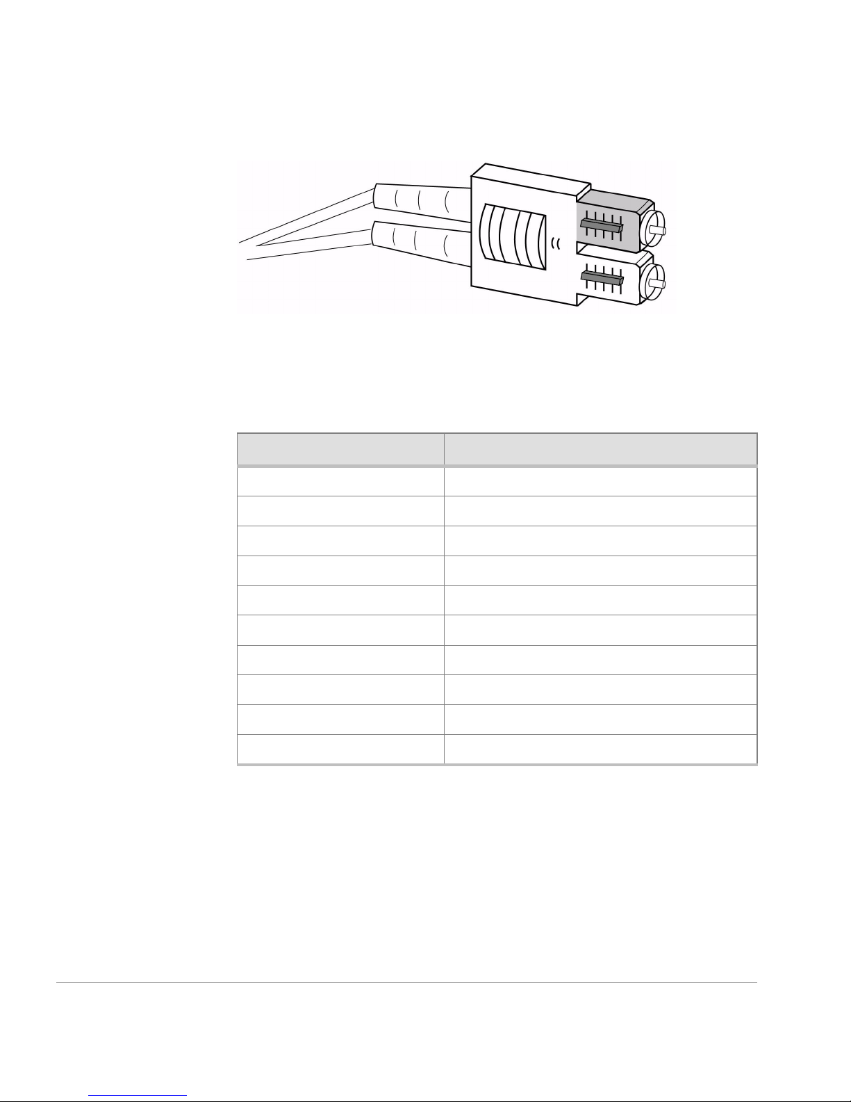
Figure 1. Dual SC Fiber Optic Plug Keyed Connector
The acceptable environmental ranges for the FC 6164 are shown in Tabl e 2.
These environmental ranges also apply to each switch.
Table 2. FC 6164 Environmental Specifications
Specification Value
Temperature (operating) 10 to 40°C
Temperature (nonoperating) -35 to 65°C
Operating humidity 5 to 85% noncondensing at 40°C
Nonoperating humidity 95% RH nonconducting at 40°C
Operating altitude 0 to 3 km above sea level
Nonoperating altitude 0 to 12 km above sea level
Operating shock 4 G, 11-MS duration, half sine
Nonoperating shock 20 G, 11-MS duration, sq.wave
Operating vibration 5 G, 0 to 3 kHz
Nonoperating vibration 10 G, 0 to 5 kHz
18 HP Surestore FC Switch 6164 Installation and Reference Guide
Page 19
Switch-level Information
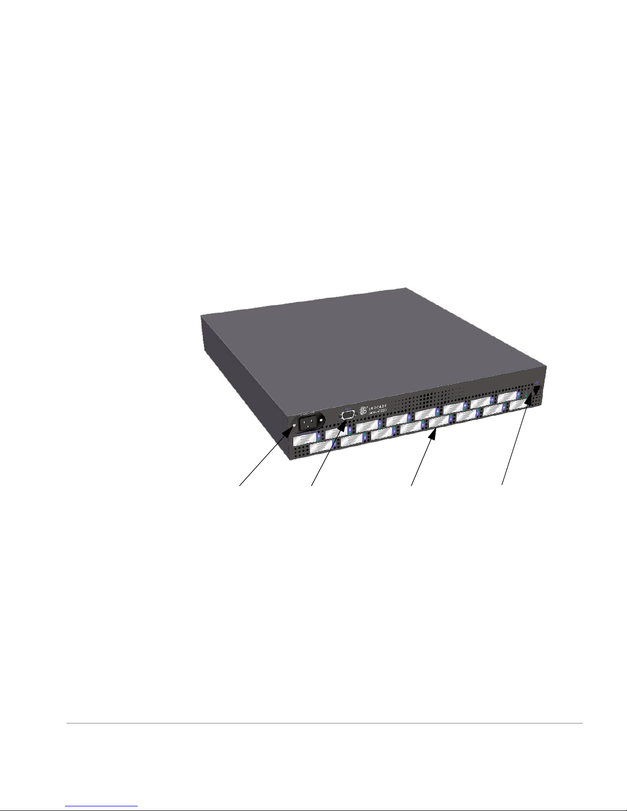
General Information About the 2250 Switch
The 2250 switch has full fabric capability, which allows the 2250 switch to
be linked to multiple other fibre channel switches to build a scalable SAN
fabric, capable of supporting large numbers of attached storage devices.
The FC 6164 supports F_Port, FL_Port, and E_Port connections and a
Distributed Name Server (DNS). There is no On/Off switch; the switch is
powered on or off when the power cable is connected or disconnected.
AC module
Figure 2.
Mechanical Specifications 19
2250 Switch
DB-9 port
GBIC port
10/100BaseT port
Page 20

Switch Specifications
Tabl e 3 lists general switch specifications for the 2250 switch.
Table 3. Switch Specifications
Specification Description
Fabric initialization Complies with FC-SW 3.2
IP over Fibre Channel
Complies with FC-IP 2.3 of the FCA profile
(FC-IP)
System architecture Nonblocking shared-memory switch
System processor Superscalar 33-Mhz Intel i960RP
Number of Fibre Channel
16 GBIC ports
ports
Fibre Channel port speed 1.0625-Gbps full duplex
Modes of operation Fibre Channel Class 2 service and Fibre
Channel Class 3 connectionless service
Aggregate switch I/O
16 Gbps, full duplex
bandwidth
Frame buffers 16 buffers per port at 2112 bytes per frame
Port to port latency Less than 2 microseconds with no contention
Data transmission range Up to 500 m (1,625 ft.) for short wave length
optical link
Chassis type Back-to-front airflow (AC power connection
2250 Switch Physical Dimensions
Table 4. 2250 Switch Physical Specifications
Rack Mount Dimensions: 1.5U, 19-in. rack mount (EIA compliant)
Weight: 20.0 lbs.
20 HP Surestore FC Switch 6164 Installation and Reference Guide
Up to 10 km (32,820 ft.) for long wave
length optical link
out front)
Page 21

Switch Memory
Power Supply
The available memory for the FC 6164 is as follows:
• Main memory: 16 MB per switch
• Flash memory: 4 MB per bank, with 2 banks in the 2250 switch
(mirrored for redundancy)
The 2250 switch is powered on when the power cable is connected to the
switch and to a power source. The switch automatically performs a power
on self test (POST), which is a diagnostic test that takes approximately 2
minutes.
The 2250 switch has a universal power supply capable of functioning
worldwide without voltage jumpers or switches. The power supply module
is autoranging in terms of accommodating input voltages and line
frequencies.
Table 5. Power Supply Requirements
Total P/S power 70 to 120 W (70-W convection, without fan;
120-W with 30 CFM forced air, with fan)
Max. switch power 60 to 70W
Input voltage 85 to 264 VAC
Input line frequency 47 to 63 Hz
Harmonic distortion Power factor correction per IEC61000-3-2
BTU rating 110 W x 3.412 BTU/hr/W = 375 BTU/hr
Environmental Specifications for each Switch
The acceptable environmental ranges for the 2250 switch are the same as
for the entire FC 6164, and are listed under “Thermal Characteristics” on
page 16.
Mechanical Specifications 21
Page 22

LED Status Indicators
Each port, and the AC power connection, has an LED that indicates the
status for that port or power connection. Table 6 provides a description of
port and AC power status indicators and possible corrective actions in case
of faulty status.
Table 6. LED Status Indicators
LED/Time
Interval
No light
showing
Status/Description Action
No light or signal carrier (no module,
no cable) for media interface LEDs.
Steady yellow Receiving light or signal carrier, but
not yet online.
Slow yellow
(on for one
Port is disabled (result of diagnostics
or port disable command).
second; off for
one second)
Fast yellow
Error, fault with port. Reset switch.
(on for 1/4
second; off for
1/4 second)
Steady green Port is online but no traffic
(connected with device over cable).
Slow green
(on for one
second; off for
Port is online but segmented
(loopback cable or incompatible
switch).
one second)
Check media
connection.
No action
required.
Reset at
management
station.
No action
required.
Check media
connection at both
ends.
Fast green
(on for 1/4
second;
(off for 1/4
second)
Flickering
green
22 HP Surestore FC Switch 6164 Installation and Reference Guide
Internal loopback (diagnostic). No action
required.
Port is online with traffic flowing
through port.
No action
required.
Page 23

Table 6. LED Status Indicators (continued)
LED/Time
Interval
Interleaving
Status/Description Action
Port is bypassed. Reset at
green and
yellow
AC Power
Status/Description Action
LED
No light
showing
No power is being supplied to the
switch.
Steady green Receiving power and switch is
online.
management
station.
Check power cord
connection to the
switch.
No action
required.
Mechanical Specifications 23
Page 24

24 HP Surestore FC Switch 6164 Installation and Reference Guide
Page 25

3
INSTALLING AND CONFIGURING
THE FC 6164
This chapter provides instructions for installing and configuring the
FC 6164.
Note
referenced in this chapter, enter
at the Telnet prompt. For example, to display information about the
fabricShow
For detailed information about any of the Fabric OS commands
help
command, enter the following:
followed by the
help fabricShow
[command name]
Installation Considerations and Safety Guidelines
WAR NING
handling and lifting equipment, such as a hydraulic lift, to reduce the
possibility of injury or product damage.
The FC 6164 weighs approximately 200 pounds. Use proper
25
Page 26

The FC 6164 is a high-port count integrated fabric comprised of six switch
modules in a rack mountable chassis.
• If installing the FC 6164 in a closed or multi-rack assembly, ensure the
air temperature measured inside the FC 6164 chassis door does not
exceed 40°C during operation.
• Ensure the airflow available to the switch fabric is at least 300 cfm
(cubic feet per minute).
• Verify that the fully-loaded chassis does not unbalance the rack or
exceed the rack’s mechanical limits, with all six FC 6164 switches
secured in the chassis and with one switch partially extended out of the
chassis.
• Verify the supply circuit, line fusing, and wire size are adequate
according to the electrical rating on the switch nameplate.
• Verify that all equipment installed in the rack has a reliable branch
circuit ground connection.
• It is strongly recommended that the EIA Rack be mechanically secured
to prevent tipping over in an earthquake.
Procedures
Use the procedures in this section to upack, install, and configure a the
FC 6164. The overall procedure of installing and configuring the FC 6164
involves the following secondary procedures, described on the indicated
pages:
1. “Unpacking the FC 6164” on page 28
2. “Installing the FC 6164 in the Rack” on page 28
3. “Configuring the FC 6164” on page 51
26 HP Surestore FC Switch 6164 Installation and Reference Guide
Page 27

Items Required
The following items must be available before you begin the installation
procedures:
• FC 6164
• 30” deep rack space, 14 rack units high and 19” wide
• Six Ethernet cables, one for each switch
• Six power outlets, one for each switch
• FC 6164 worksheet, provided in Appendix A, “FC 6164 Worksheet”
• Serial cable connected to the workstation, long enough to connect to
each of the switches in the chassis
• Workstation that has a terminal emulator application (such as
HyperTerminal)
• Six unused IP addresses
• Ethernet connection between the workstation and the FC 6164 (such as
through a hub)
• #2 Phillips screwdriver
• T20 Torx screwdriver
• Genie lift (to transport the switch) For information on the lift, see:
http://www.genielift.com/ml-series/ml-1-2.html
or
http://slick2.atl.hp.com/ceworld/siteservices/tools/genie/genielift_ordering.htm
Installing and Configuring the FC 6164 27
Page 28

Unpacking the FC 6164
To unpack the FC 6164:
1. Open the shipping carton.
2. Remove all of the packaging materials.
3. Remove the screws holding the FC 6164 to the pallet.
Installing the FC 6164 in the Rack
This section provides the step-by-step procedure for installing the
FC Switch 6164 in either an HP rack or a Compaq/Rittal 19-inch rack.
Note
Most of the steps in this procedure are unnecessary if the FC 6164
was installed at an HP integration center prior to shipment. However, Steps
18 and 19 (assembling and installing the plenum) and Step 21 (installing
the switch door) must be performed for factory-integrated switches (see
pages 47 and 50).
Rackmount Safety Guidelines
In a rackmount installation, follow these safety guidelines:
• When installing a switch in a closed or multi-rack assembly, make
certain the air temperature, measured at the front panel, does not exceed
40° C during operation.
• Ensure that the airflow available to the switch is at least 300 cfpm.
• Verify the supply circuit, line fusing, and wire size are adequate. Refer
to the switch’s nameplate for its power requirements.
• Verify that all equipment installed in the rack has a reliable ground
connection. Do not rely on connection to a branch circuit, such as power
strips.
• Route and support the power cord to ensure that it does not become
crimped or damaged and to prevent it from interfering with other
equipment and cabling installed in the rack.
• The FC 6164 weighs approximately 200 pounds. A lift is required to
move and position the switch safely, and at least two people are required
28 HP Surestore FC Switch 6164 Installation and Reference Guide
Page 29
to lift and position the switch onto the lift. Two or more people are also
required to move the switch from the lift into the rack and when
positioning the switch in the rack. Move the switch chassis slowly and
carefully at all times, and continue supporting it until it is correctly
positioned on the rail tray and fastened to the rack. Use extreme caution
when handling or transporting the switch to prevent injury to personnel,
damage to the switch, and/or damage to the rack and other equipment
mounted in it.
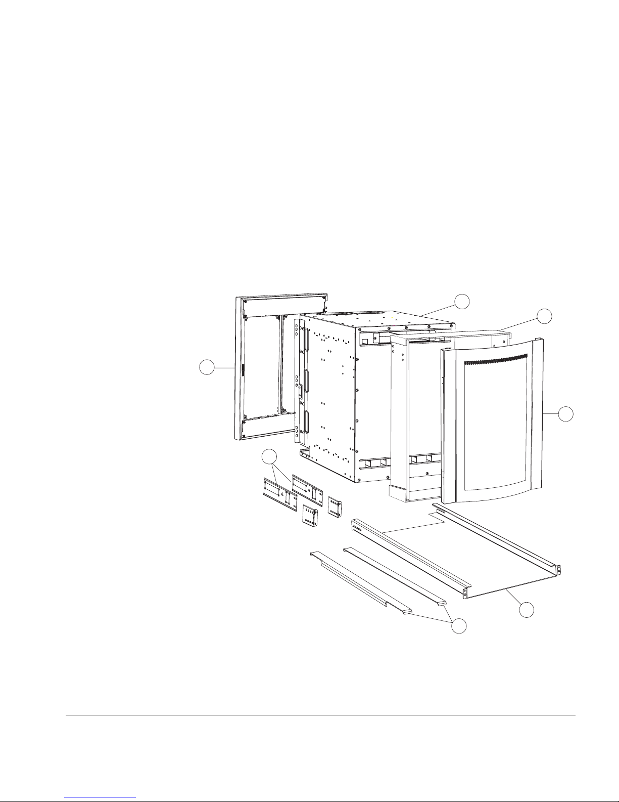
Package Contents
Figure 3 shows the major items contained in the FC 6164 shipping
carton(s). Table 7 lists the contents of the shipping carton.
A
G
B
F
F
Figure 3. Major Items Contained in the Shipping Carton(s)
C
D
E
Installing and Configuring the FC 6164 29
Page 30

Table 7. Contents of the Shipping Carton(s)
ASwitch
B Plenum kit (4 rectangular sheets of Lexan with 6 adhesive strips
pre-attached) (HP P/N A7326-87903)
C Front bezel (HP P/N A7326-40001)
D Rail Tray kit (Rail tray, 2 brackets, 2 M5 Tinnerman nuts, 4 M5 Torx
screws) (HP P/N A6534-60016)
E Shim plates (2 ea. HP P/N A7326-87904)
F Rack Mount Bracket set (2 Rack-Mount brackets)
(HP P/N A7326-87901)
G Switch door (part of Accessory kit [HP P/N A7326-70001], which
also includes: Software CD, Documentation CD, and Serial cable)
H Miscellaneous hardware: (not shown) (HP P/N A7326-87905)
Note: The hardware in the Standard hardware package (unmarked plastic bag)
is required to install the switch in an HP rack. Some of the hardware in the
Standard hardware package and the hardware in the Compaq/Rittal hardware
package is required to install the switch in a Compaq/Rittal rack.
Standard hardware package
8 #8-32 x .375-inch (.3125) flat-head screws w/patchlock.
8 M5 Torx screws with lock washers
6 M5 Tinnerman nuts
4 1/4-20 x 1/2-inch Phillips pan-head screws with lock washers
Compaq/Rittal hardware package
6 #10-32 Tinnerman nuts
6 #10-32 x 5/8-inch Phillips pan-head screws with captive lock washers
6 Spacers
4 1/4-inch flat washers
4 M5 flat washers
Note
A package containing two mounting rails may be included with the
switch. These rails are not used and can be discarded.
30 HP Surestore FC Switch 6164 Installation and Reference Guide
Page 31

Hardware Identification
Figure 4 contains drawings and descriptions of the hardware used when
installing the FC 6164 in an HP rack or a Compaq/Rittal rack. Use this key
to help identify the hardware specified in the installation procedure in this
chapter.
#8-32 x .375-inch flat-head Phillips screw
M5 Torx screw with captive lock washer
M5 Tinnerman nut
1/4-20 x 1/2 inch Phillips screw and washer
#10-32 Tinnerman nut
#10-32 X 5/8-inch pan-head Phillips screw
Spacers for Compaq/Rittal racks
1/4-inch flat washer
M5 flat washer
Figure 4. Hardware Key
Installing and Configuring the FC 6164 31
Page 32

Installing the FC 6164 in the Rack
WAR NING
Mount the switch as low as possible in the rack to ensure that
the weight of the switch does not make the rack unstable. 15 Rack Units
(RUs) are required (see Figure 5).
Back
of
switch
15 RU
Figure 5. Switch Mounted Back-to-Front and Low in the Rack
CAUTION
of the rack. When the switch is mounted this way, the air flows through the
switch in the same direction as it does through the other equipment in the
rack (see Figure 5).
32 HP Surestore FC Switch 6164 Installation and Reference Guide
Front of rack
The switch must be installed with the front end facing the back
Page 33

Note
In these instructions, the 15 RUs used to mount the switch are called
RU-1 through RU-15 (see Figure 5); RU-1 is the lowest of the 15 RUs.
1. Check the contents of the shipping carton and the kits within the carton
to verify that all of the required parts and hardware are available (see
Figure 3, Tab le 7, and Figure 5).
2. Choose a mounting location in the rack for the switch (see the WARNING
at the beginning of this section and Figure 5).
3. Install the rail tray in the rack:
a. Locate the lowest RU of the 15 you chose for mounting the switch
(this is RU-1).
b. Attach the rear rail-tray brackets to the rear rack uprights at RU-1:
For an HP rack, use 1 M5 torx screw for each bracket (see Figure 6).
For a Compaq/Rittal rack, insert spacers in the upper and lower holes
where the brackets are to be mounted, position the brackets on the
spacers, and use 1 M5 torx screw with captive lock washer and two
M5 flat washers to attach each bracket (see Figure 6).
Installing and Configuring the FC 6164 33
Page 34

HP rack
M5 Screw
with attached
lock washer
Compaq/Rittal
rack
M5 Screw
with attached
lock washer
Figure 6. Installing the Rear Rail-Tray Brackets
M5
flat
washer
Spacer
M5
flat
washer
Rear Tray
bracket
Rear Tray
bracket
Note
mounting instructions on the label attached to the rail tray (some rail
trays do not have this label).
34 HP Surestore FC Switch 6164 Installation and Reference Guide
When installing the rail tray in a Compaq/Rittal rack, ignore the
Page 35

c. Install Tinnerman nuts for the top holes of RU-1 in both of the rack’s
front uprights (see Figure 7).
Note
The Tinnerman nuts used for the two types of racks (HP and
Compaq/Rittal) are of different styles and different sizes. Refer to
Figure 5 and Figure 7 to identify the correct Tinnerman nut to use with
the rack you are installing the switch in.
Tinnerman
nut
Spacer
Inner surface of
Outer surface of
HP rack
Compaq/Rittal
rack
Figure 7. Installing Tinnerman Nuts and Spacers on the Front Uprights
d. For a Compaq/Rittal rack, insert spacers in the holes immediately
below the Tinnerman nuts you inserted in Step 3c (see Figure 7).
Installing and Configuring the FC 6164 35
Page 36

e. Orient the rail tray as shown in Figure 8, and insert it into the rack
from the front. The slots in the sides of the rail tray must slide over
the posts on the rear rail-tray brackets, and the posts on the rail tray’s
front mounting flanges must be inserted in the center holes of RU1.
Figure 8. Inserting the Rail Tray in the Rack
f. Insert M5 torx screws through the top holes in both of the rail tray
mounting flanges. The screws pass through the holes in the rack
uprights and thread into the Tinnerman nuts you installed on the
uprights in Step 3c. Tighten the screws.
36 HP Surestore FC Switch 6164 Installation and Reference Guide
Page 37

4. Place a shim plate on each side of the rail tray (see Figure 9).
Figure 9. Placing the Shim Plates on the Rail Tray
CAUTION
The shim plates must be placed on top of both sides of the
rail tray to prevent misalignment between the mounting holes in the
switch flanges and the holes in the rack uprights.
Installing and Configuring the FC 6164 37
Page 38

5. Insert Tinnerman nuts onto the center holes of RU-5 and the top holes of
RU-12 in both of the rack’s rear uprights (see Figure 10).
12
11
M5 Tinnerman nuts
5
4
#10-32Tinnerman nuts
Rack uprights
1
HP Rack Rittal Rack
Figure 10. Installing Tinnerman Nuts in RU-5 and RU-12
12
11
5
4
1
6. Install the rack-mount brackets on the switch:
a. The rack-mount brackets consist of a stationary plate and an adjustable
plate that are attached to each other with two screws. Remove the
screws that attach the adjustable plates to the stationary plates. Set the
screws and the adjustable plates aside for later use (see Figure 11).
Figure 11. Separating the Rack-Mount Bracket Plates
38 HP Surestore FC Switch 6164 Installation and Reference Guide
Page 39

a. Use four #8-32 x 5/16-inch Phillips flat-head screws to mount one of
the stationary plates onto each side of the switch. The plates must be
oriented so that the end of the plate that has the slotted holes protrudes
past the back of the switch, and if the plate has arrows stamped into
it, the arrows must point up (see Figure 12). Do not tighten the screws
fully at this time.
Note
Some stationary plates have arrows stamped into them, and some
do not. The arrow determines which side of the switch the plate must be
mounted on. If the stationary plates provided with the switch do not
have arrows, they can be mounted on either side.
Installing and Configuring the FC 6164 39
Figure 12. Mounting the Rack-Mount Bracket Stationary Plates to the Switch
Note
If you have adequate access to the back of the rack to insert the
switch from the back, skip Steps 7, 8, and 9. If you do not have adequate
access to the back of the rack, proceed with Step 7.
Page 40

Note
If you cannot insert the switch into the rack from the back, you
must remove several pieces of hardware from the sides of the switch at
the front end as described in Steps 7, 8, and 9. If you have adequate
access to insert the switch into the rack from the back, you can skip
these steps.
7. Remove the four #6-32 x ¼-inch flat-head screws that attach each of the
two hinge plates to the left side of the switch at the front end (see
Figure 13). Set the screws and the hinge plates aside for later use.
x 8
Figure 13. Removing the Hinge Plates from the Switch
40 HP Surestore FC Switch 6164 Installation and Reference Guide
Page 41

8. Remove the two screws that attach the latch plate to the right side of the
switch at the front, and remove the latch plate (see Figure 14). Set the
latch plate and the screws aside for later use.
Note
The latch plate fits through a cutout in the rack-mounting flange
on the right side of the switch.
Rack-mounting
flange
Latch plate
9. Remove the eight #10-32 Phillips screws that attach each of the
Installing and Configuring the FC 6164 41
Figure 14. Removing the Latch Plate and the Mounting Flanges
rack-mounting flanges to the sides of the switch at the front, and remove
the rack-mounting flanges (see Figure 14). Set the rack-mounting flanges
and the screws aside for later use.
Page 42

WAR NING
If the rack you are mounting the switch in is on wheels,
make sure the leveling feet are down or the wheels are locked to prevent
the rack from moving while you are installing the switch. Failure to
prevent the rack from moving could result in injury to personnel and/or
damage to the switch, the rack, or other equipment.
10.Insert the switch in the rack:
WAR NING
The FC 6164 weighs approximately 200 pounds. A lift is
required to move and position the switch safely, and at least two people
are required to lift and position the switch onto the lift. Two or more
people are also required to move the switch from the lift into the rack
and when positioning the switch in the rack. Move the switch chassis
slowly and carefully at all times, and continue supporting it until it is
correctly positioned on the rail tray and fastened to the rack. Use
extreme caution when handling or transporting the switch to prevent
injury to personnel, damage to the switch, and/or damage to the rack and
other equipment mounted in it.
a. Place the switch on a lift. If you are installing the switch from the front
of the rack, orient the switch so its front end FACES THE FRONT OF
THE RACK is at the edge of the lift. If you are installing the switch
from the back of the rack, orient the switch so that its back end is at
the edge of the lift. (The switch must be installed so the front of the
switch faces the back of the rack.)
b. Position the lift close to the rack, and raise it until the bottom of the
switch is even with or very slightly above the top surfaces of the shim
plates that you positioned on top of the rail tray in Step 4.
c. Carefully slide the switch from the lift onto the shim plates on the rail
tray.
d. Position the switch so that its front end protrudes out the back of the
rack approximately six inches.
42 HP Surestore FC Switch 6164 Installation and Reference Guide
Page 43

11.If you inserted the switch into the rack from the back, skip this step.
Reinstall the removed hardware:
a. Use the 16 #10-32 Phillips screws you removed in Step 9 to re-attach
the rack-mounting flanges to the switch (see Figure 14).
b. Use the two screws you removed in Step 8 to re-attach the latch plate
(see Figure 14). Make sure that there is a gap of approximately
3/16-inch between the edges of the latch plate and the edges of the
cutout in the rack-mounting flange.
c. Orient the hinge plates so that the sides that have the loops face each
other (see Figure 15). Use the eight #6-32 x ¼-inch flat-head screws
you removed in Step 7 to re-attach the hinge plates to the left side of
the switch at the front end (see Figure 13).
Loops
Figure 15. Orienting the Hinge Plates Prior to Reinstallation
Installing and Configuring the FC 6164 43
Page 44

12.Re-attach the rack-mount bracket adjustable plates:
a. From the front of the rack, slide the switch forward a small distance.
b. Insert one of the adjustable plates into one the stationary plates (see
Figure 16).
Figure 16. Re-attaching the Rack-Mount Bracket Adjustable Plates
c. Insert the screws you removed in Step 6a through the slotted holes in
the stationary plate and into the second set of threaded holes in the
adjustable plate from the rack-mounting flange (see Figure 16). Do
not tighten the screws at this time.
d. Repeat Steps b and c for the rack-mount bracket on the opposite side
of the switch.
e. Move the switch forward in the rack as far as it can go. The amount
of movement is limited by the rack-mount bracket adjustable plates
contacting the rack uprights.
44 HP Surestore FC Switch 6164 Installation and Reference Guide
Page 45

WAR NING
The FC 6164 weighs approximately 200 pounds.Two or
more people are required when positioning the switch in the rack. Move
the switch chassis slowly and carefully at all times, and continue
supporting it until it is correctly positioned on the rail tray and fastened
to the rack. Use extreme caution when handling or transporting the
switch to prevent injury to personnel, damage to the switch, and/or
damage to the rack and other equipment mounted in it.
f. Put flat washers on four ¼-20 screws with captive lock washers, and
insert the screws through the holes in the rack uprights and into the
threaded holes in the flanges of the rack-mount bracket adjustable
plates (see Figure 16). Do not tighten the screws at this time.
13.From the back of the rack, insert four #10-32 x 5/8-inch Phillips pan-head
screws with captive lock washers through the holes in the rack-mount
flanges attached to the front end of the switch and into the Tinnerman nuts
you placed in the rack in Step 5 (see Figure 10 and Figure 17). Tighten
the screws fully.
Note
For an HP rack, you may have to adjust the positions of the
Tinnerman nuts to get them to align properly with the holes in the rack
uprights. If necessary, use a screwdriver blade inserted through the holes
in the rack uprights to reposition the Tinnerman nuts.
Installing and Configuring the FC 6164 45
Page 46

Figure 17. Attaching the Rack-Mount Flanges to the Rack
14.Fully tighten the screws that attach the rack-mount bracket adjustable
plates to rack uprights, then fully tighten the screws that attach the
adjustable plates to the stationary plates and the screws that attach the
stationary plates to the switch chassis (see Figure 16).
46 HP Surestore FC Switch 6164 Installation and Reference Guide
Page 47

15.Assemble the plenum:
a. Position the bottom panel of the plenum on a flat surface with the two
folded ends facing up (see Figure 18).
Adhesive
strips
Adhesive
strips
Bottom of
plenum
Adhesive
strips
Figure 18. Assembling the Plenum
b. Remove the paper backing from one of the adhesive strips on one of
the plenum side panels, and carefully position the side panel against
the inner surface of one of the folded ends of the bottom panel (see
Figure 18). Press the side panel firmly against the upright end of the
bottom panel to ensure that the adhesive strip on the side panel makes
full contact with the end of the bottom panel. You can use a screwdriver
handle to increase the pressure you apply when joining the parts.
c. Repeat Step 15b for the other side panel.
d. Remove the paper backing from the adhesive strips on the upper ends
of both plenum side panels.
Installing and Configuring the FC 6164 47
Page 48

e. Carefully position the plenum top panel over the side panels so that
the folded ends of the top panel face down and are outside of the side
panels.
f. With the top panel aligned with the side panels, press one of the side
panels firmly against the inner surface of the folded end of the top
panel to ensure that the adhesive strip on the side panel makes full
contact with the folded end of the top panel. Repeat this step for the
other side panel.
16.Install the plenum in the rack:
a. Remove the paper backing from the two adhesive strips on the bottom
surface of the plenum.
b. Position the plenum against the back of the switch and slide it down
until the adhesive strips on the underside of the plenum contact the
shim plates that are on top of the rail tray (see Figure 19).
Back
of
switch
Figure 19. Inserting the Plenum
c. Press down firmly on the bottom panel of the plenum above the
adhesive strips to ensure that the adhesive strips make full contact with
the shim plates on top of the rail tray.
48 HP Surestore FC Switch 6164 Installation and Reference Guide
Page 49

17.Install the front bezel:
a. Orient the front bezel so that its outer surface is facing you.
a. Align the bottom end of the front bezel with the bottom edge of the
rail tray (see Figure 20). There are two alignment posts and two spring
clips on each side of the bezel that grip the rack uprights and hold the
bezel in position. Each of the lower alignment posts fits into the second
unused hole above the front mounting flange on each side of the rail
tray.
Installing and Configuring the FC 6164 49
Figure 20. Installing the Front Bezel
b. Press the sides of the bezel against the rack uprights until the bezel
snaps into place. Snap the bottom end in first and then the top end.
c. Inspect the bezel to ensure that it is installed so that its top edge is
aligned with the top surface of the switch.
Page 50

18.Install the switch door:
a. Rotate the knobs on the switch door so that they are in the down
position and the springs are compressed.
b. Position the door so that the hinge pins are between the loops on the
hinge plates mounted on the switch (see Figure 15 and Figure 21).
Note
When you rotate the door to the closed position, the
spring-loaded hinge pins will snap into the loops on the hinge plates.
Figure 21. Installing the Switch Door
Note
be installed, and it must be kept closed during normal operation.
50 HP Surestore FC Switch 6164 Installation and Reference Guide
To ensure that the switch does not emit RFI, the switch door must
Page 51

19.Connect each of the six power cables to a power source, and verify that
each power cable is firmly seated in the power connector of the
corresponding switch.
Note
power on self test (POST), which takes approximately two minutes and
is complete when LED activity stops. This test can be disabled by
entering the following at the Telnet prompt:
If a malfunction occurs during POST, error messages are written to the
system error log, which is accessible by Telnet. If the malfunction
prevents the switch from completing the boot process, the switch
prompt does not display when the serial port is connected.
Configuring the FC 6164
1. Obtain a copy of the FC 6164 worksheet provided in Appendix A, “FC
6164 Worksheet”, and enter the IP address and related information for
each switch, as provided by the LAN (local area network) administrator.
2. Replace the factory IP address and related information for each of the six
switches with the information provided by the LAN administrator.
a. Disable any serial communication programs running on the
Each time the switch is powered on, it automatically performs a
diagDisablePost
workstation, such as synchronization programs for a PDA.
b. Remove the shipping plug from the serial port on switch 1 (the switch
on the far left) and insert the serial cable provided with the FC 6164.
c. Insert one end of a serial cable into the serial port.
d. Connect the other end of the serial cable to an RS-232 serial port on
the workstation. If necessary, you can remove the adapter to allow for
RJ45 serial connection to the workstation.
Installing and Configuring the FC 6164 51
Page 52

e. Open and configure a terminal emulator application (such as
HyperTerminal on Windows 95 or NT, or TERM in a UNIX
environment) as follows:
Parameter Value
Bits per second: 9600
Databits: 8
Parity: None
Stop bits: 1
Flow control: None
Function arrows and Ctrl keys act as: Terminal keys
Emulation: Autodetect
f. From the terminal emulator application, log on to the first switch
through the serial connection.
g. Specify the new IP address by entering the following:
ipAddrSet
h. Enter the following information at the corresponding prompts:
Ethernet IP Address [current]:
–
Enter new Ethernet IP
address (the default is 10.77.77.77).
Ethernet Subnetmask [current]:
–
Enter new Ethernet
subnetmask (the default is 0.0.0.0).
Fibre Channel IP Address [current]:
–
Enter new fibre
channel IP address if desired.
Fibre Channel Subnet Mask [current]:
–
Enter new fibre
channel subnet mask if desired.
Gateway Address [current]:
–
Enter new gateway address
(the default is 172.17.1.1).
Set IP address now? [y = set now, n = next
–
reboot]:
Enter “y” to set now by rebooting the switch.
i. You can verify the address was set correctly by entering the following:
IPaddressShow
52 HP Surestore FC Switch 6164 Installation and Reference Guide
Page 53

j. Remove the serial cable and replace the shipping plug.
k. Repeat steps a through j for the remaining five switches in the FC 6164.
Note
The serial port is intended for initial setting of the IP address and
for service purposes. Using the serial port during normal switch
operation or for regular maintenance is not recommended.
3. Connect all six switches by Ethernet to the LAN on which the workstation
resides.
a. Remove the shipping plug from the Ethernet port on each switch.
b. Insert one end of an Ethernet cable in each Ethernet port.
c. Connect the other end to an existing Ethernet 10/100 Base-T LAN.
Note
When the Ethernet connection is made, remote Telnet and Web
access is available. If the FC 6164 becomes connected to a larger
network by this step, ensure that the system is not being modified from
more than one connection during the following steps.
4. Modify the domain IDs if desired.
Note
The default domain IDs on the six original switches shipped with
the FC 6164, starting with switch 1, are 231, 232, 233, 234, 235, and
236. If a domain ID is already in use when the FC 6164 is connected to
the fabric, the domain ID for the new switch is automatically reset to a
unique value. The current domain IDs in use can be determined by
issuing the Telnet command
fabricShow
on a switch connected to the
larger SAN fabric.
Installing and Configuring the FC 6164 53
a. Log on with administrative privileges to the first switch, using a Telnet
connection.
b. Disable the switch by entering the following:
switchDisable
c. Enter the following:
configure
Page 54

d. Enter “Y” after the “
Fabric parameters (yes, y, no, n): [no] y
Fabric parameters
” prompt.
e. Enter a unique domain ID (such as the domain ID used by the previous
switch, if still available).
Domain: (1..239) [1] 3
f. Complete the remaining prompts (or press CTRL+D to accept the
remaining settings
without completing all the prompts).
g. Re-enable the switch by entering the following:
switchEnable
h. Repeat Steps a through g for the remaining switches.
5. Specify the desired status policies for your fabric.
a. Log on to the first switch by Telnet.
b. Enter the following at the prompt:
switchStatusPolicySet
c. Specify the desired status policies. To completely deactivate the alarm
for a particular condition, enter “0” at the prompt for that condition.
d. Repeat Steps a through c for the remaining five switches in FC 6164.
6. Check the FC 6164 for port or ISL issues.
a. Log on with administrative privileges by Telnet to one of the switches
in the integrated fabric.
b. Enter the following at the Telnet prompt:
islTopoShow
This command provides general information about all the switches in
the FC 6164. Any problems are indicated by an error condition in the
Status column.
54 HP Surestore FC Switch 6164 Installation and Reference Guide
Page 55

7. Check each switch for port or ISL issues.
a. Log on with administrative privileges by Telnet to one of the switches
in the group.
b. Enter the following at the Telnet prompt:
islTopoCheck
This command provides detailed information about the local switch
(the switch currently accessed by Telnet). If there are any problems,
the Status column indicates an error condition.
c. Repeat Steps a through b for the remaining switches in the group.
8. Add GBICs and cables as needed to the user ports.
a. Remove the shipping plug from the user ports to be used.
b. Position the GBIC so that the key (the ridge on one side) on the GBIC
is aligned with the slot in the user port.
c. Insert each GBIC into the port until it is firmly seated and the latching
mechanism locks. The GBIC module is keyed so that it can be inserted
in only one way. If the module does not slide in easily, try reversing it.
d. Connect fiber optic cables to the user GBICs as appropriate to the
fabric topology.
9. Back up the configuration for each of the six switches in the FC 6164,
after any zoning configurations and other changes are completed. This
ensures a complete configuration is available for uploading to a
replacement switch, if required.
a. From the workstation, establish a Telnet connection to the switch you
want to back up, and log on with administrative privileges.
b. Enter the following command to download the configuration to the
server.
configupload
Note
A routine backup of the configuration for each switch in the FC
6164 is recommended at regular intervals, to ensure a fairly current
configuration is available for uploading to a replacement switch, if
required.
Installing and Configuring the FC 6164 55
Page 56

56 HP Surestore FC Switch 6164 Installation and Reference Guide
Page 57

MAINTENANCE PROCEDURES
Switch Replacement Procedure
Use this procedure to remove and replace any of the six switches in the FC
6164.
4
Note
referenced in this chapter, enter
Telnet prompt. For example, to display information about the
command, enter the following:
The overall procedure of replacing a switch involves the following
secondary procedures, described on the indicated pages:
1. “Preparing to Remove the Switch From the FC 6164” on page 59
2. “Physically Uninstalling the Switch” on page 61
3. “Installing the New Switch in the Chassis” on page 63
4. “Configuring the New Switch” on page 64
5. “Adding the New Switch to the Integrated Fabric” on page 69
For detailed information about any of the Fabric OS commands
help
help fabricShow
plus the
[command name]at
fabricShow
the
57
Page 58

Note
The steps are numbered consecutively throughout all the secondary
procedures.
Time Required
Approximately 45 minutes.
Items Required
• Silkworm 2250 switch
• Fabric OS a2.4.1
• FC 6164 Fabric Watch profile. (Configuration profile)
• Computer workstation with access to the switches in the FC 6164.
• FC 6164 worksheet, provided in Appendix A, “FC 6164 Worksheet”.
• Number 2 Phillips screwdriver.
• If more than one switch is being replaced at the same time, labels are
needed for identifying the different Ethernet and serial cables when they
are disconnected.
Procedure
Note
If multiple switches are being replaced, the simplest approach is to
replace one switch at a time.
58 HP Surestore FC Switch 6164 Installation and Reference Guide
Page 59

Figure 22. FC 6164 with All Switches Installed (Fiber Optic Cables and Other Cables Not Shown)
Preparing to Remove the Switch From the FC 6164
1. Identify the worldwide name (WWN) and the domain ID of the faulty
Maintenance Procedures 59
switch. If this information is already recorded on the FC 6164 worksheet
(provided in Appendix A, “FC 6164 Worksheet”), continue with step 2.
If the information is not already recorded, perform Steps, a through c.
a. From a computer workstation, establish a Telnet connection to one of
the functioning switches in the FC 6164, and log on with
administrative privileges.
Page 60

b. Enter
sgroupShow
at the Telnet prompt to display group information.
This command lists the WWNs for each switch in the FC 6164,
beginning with switch 1 (the switch on the far left).
Example
reg101:admin> sgroupShow
Group Type Group Name Member WWN
==============================================
S64_6_1 East Lab 10:00:00:60:60:10:60:11
10:00:00:60:60:10:60:22
10:00:00:60:60:10:60:33
10:00:00:60:60:10:60:44
10:00:00:60:60:10:60:55
10:00:00:60:60:10:60:66
Note
switches in the larger SAN fabric. For details about the
fabricShow
The
command provides information about all the
fabricShow
command, refer to the Fabric OS v2.2 manual.
c. Record the WWNs, domain IDs, IP addresses, and other relevant
information for all switches in the group on the FC 6164 worksheet
(provided in Appendix A, “FC 6164 Worksheet”).
Note
Keep the completed worksheet readily available for future work
on the FC 6164. However, do not tape the worksheet to the front door or
rear panel, to prevent disruption of airflow through the chassis.
2. If the faulty switch is partly or fully operational, back up the current
configuration.
60 HP Surestore FC Switch 6164 Installation and Reference Guide
Page 61

Note
Creating a backup copy of the switch configuration is
recommended for each switch in the FC 6164. This preserves zoning
and other switch-specific information.
a. From a workstation, establish a Telnet connection to the switch that is
being replaced, and log on as administrator.
b. Enter the following command to disable the switch:
switchDisable
c. Enter the
configupload
command to upload the configuration to the
server.
Physically Uninstalling the Switch
3. Physically disconnect the faulty switch.
Note
These switches do not have an On/Off button; they are powered
on or off by connecting or disconnecting the power cord. It is not
necessary to power off the switches that are connected to the faulty
switch.
a. Disconnect the power cable, leaving the cable in the channel below
the switch.
b. Disconnect the Ethernet cable and the serial cable. If disconnecting
more than one switch at a time, label each of the Ethernet and serial
cables (if used) with the switch number before disconnecting.
CAUTION
The fiber optic cables are fragile and should not be bent to a
radius of less than 0.5 inches.
Maintenance Procedures 61
c. Ensure that each of the fiber optic cables are still labeled with the port
and switch number.
Note
The exact cabling configuration shown in the diagram must be
implemented in order for the FC 6164 to operate correctly.
Page 62

d. Disconnect each of the fiber optic cables from the faulty switch by
firmly grasping the connector housing (black) on the cable, and pulling
the cable from the GBIC.
4. Remove the switch from the chassis.
a. Unscrew the two 1/4-20 Phillips self-retaining screws that fasten the
switch brackets to the chassis (see Figure 23). Use a number 2 Phillips
screwdriver.
b. Carefully move the cable harness out of the way so that the switch you
can slide forward without bending the cables.
c. Slide the switch forward and remove from the chassis.
5. Remove the two mounting brackets from the switch by unscrewing the
four 8-32 x 5/16 long Phillips panhead screws from each bracket. Set the
brackets and screws aside for the new switch.
Figure 23. FC 6164 with the Switch Mounting Brackets (Shown in Exploded
View)
62 HP Surestore FC Switch 6164 Installation and Reference Guide
Page 63

6. Remove all the GBICs from the faulty switch.
Note
Refer to the GBIC manufacturer’s documentation for specific
instructions about inserting and removing GBICs.
Installing the New Switch in the Chassis
7. Insert the GBICs into the new switch, inserting each GBIC into the port
until it is firmly seated and the latching mechanism becomes locked.
The GBIC module is keyed so that it can be inserted in one way only. If
the module does not slide in easily, try reversing it. The GBIC
D-connector must line up with the D-connector inside the GBIC port.
8. Install the mounting brackets on the new switch.
a. Position one of the brackets flat against the side of the switch, so that
the end with the bent lip is at the front of the switch (see Figure 23),
and align the holes in the bracket with the holes in the side of the
switch.
b. To ensure correct bracket alignment, assemble screws in the following
pattern:
Position and finger tighten the first 8/32 x .312 panhead Phillip
screw in the smallest hole in the bracket.
Position and finger tighten the second 8/32 x .312 panhead Phillip
screw in the oblong (slotted) hole.
Position and finger tighten the remaining two 8/32 x .312 panhead
Phillip screws in the remaining two holes.
Tighten all four screws to a torque of 8 inch-pounds.
c. Repeat Steps a through b with the second bracket on the other side of
the switch.
9. Install the new switch in the chassis.
a. Orient the switch so that the power connector is at the bottom of the
chassis (see Figure 23), and slide the switch into the available space.
b. Tighten the two self-retaining screws that fasten the switch brackets
to the chassis, using a number 2 Phillips screwdriver to tighten to 40
inch-pounds.
Maintenance Procedures 63
Page 64

10.Connect the following:
– power cable to the power connector
– serial cable to the serial port (if used)
– Ethernet cable to the Ethernet port
Note
Do not connect the ISL (interswitch link) or user fiber optic
cables until after the switch is configured.
Configuring the New Switch
Note
The switch can be accessed simultaneously from multiple
connections; ensure that the system is not modified from more than one
connection during the following procedure.
11.Replace the factory IP address and related information with the address
information used by the previous switch.
a. Connect the new switch to a workstation by serial cable.
b. Open and configure a terminal emulator application (such as
HyperTerminal) as follows:
Parameter Value
Bits per second: 9600
Databits: 8
Parity: None
Stop bits: 1
Flow control: None
Function arrows and Ctrl keys act as: Terminal keys
Emulation: Autodetect
c. From the terminal emulator application, log on to the new switch
through the serial connection.
64 HP Surestore FC Switch 6164 Installation and Reference Guide
Page 65

d. Specify the new IP address by entering the following:
ipAddrSet
e. Enter the following information at the corresponding prompts:
Ethernet IP Address [current]:
–
Enter new Ethernet IP
address (the default is 10.77.77.77).
Ethernet Subnetmask [current]:
–
Enter new Ethernet
subnetmask (the default is 0.0.0.0).
Fibre Channel IP Address [current]:
–
Enter new fibre
channel IP address if desired.
Fibre Channel Subnet Mask [current]:
–
Enter new fibre
channel subnet mask if desired.
Gateway Address [current]:
–
Enter new gateway address
(the default is 172.17.1.1).
Set IP address now? [y = set now, n = next
–
reboot]:
Enter “y” to set the IP address now by rebooting the
switch.
f. You can verify the address was correctly set by entering the following:
ipAddrShow
12.Log on with administrative privileges to the new switch, using a Telnet
connection.
13.From a computer workstation, disable the diagnostic tests that run after
each reboot by entering the following at the Telnet prompt:
diagDisablePost
14.Set the domain ID to the value used by the previous switch, if still
available.
The default domain IDs on the six original switches shipped with the FC
6164 are (starting with switch 1) 231, 232, 233, 234, 235, and 236.
Maintenance Procedures 65
Page 66

Note
If the domain ID (whether the default or a selected ID) is already
in use when the switch is connected to the fabric, it is automatically
reset to a unique value. You can determine which domain IDs are in use
by issuing the Telnet command
fabricShow
on one of the switches in
the integrated fabric.
a. Disable the switch by entering the following:
switchDisable
b. Enter the following:
configure
c. Enter “Y” after the “
Fabric parameters (yes, y, no, n): [no] y
Fabric parameters
” prompt.
d. Enter a unique domain ID (such as the domain ID used by the previous
switch, if still available).
Domain: (1..239) [1] 3
e. Complete the remaining prompts (or press Ctrl+D to accept the
defaults without completing the prompts).
f. Re-enable the switch by entering the following:
switchEnable
15.Download the switch configuration, if one was uploaded from the
previous switch (see Step 2).
a. Disable the switch by entering the following:
switchDisable
b. Enter the following at the Telnet prompt to download the configuration
from the server to the switch:
configDownload
Several prompts display to gather information about the file being
downloaded.
66 HP Surestore FC Switch 6164 Installation and Reference Guide
Page 67

c. Enter the requested information at the prompts, pressing Enter after
each entry:
Server Name or IP Address [host]:
–
Name or IP address
of computer on which configuration file is located.
User Name [user]:
–
File Name [/usr/switch/firmware]:
–
Login name required to access computer.
Filename or
absolute path of configuration file.
Protocol (RSHD or FTP) [rshd]:
–
Press Enter to use
RSHD, or enter FTP to use FTP protocol.
Password:
–
Enter the FTP password (only displays if FTP
protocol was selected).
d. Reboot the switch by entering the following at the prompt and pressing
Enter:
reboot
e. Re-enable the switch by entering the following:
switchEnable
16.If no previous switch configuration was downloaded, or the switch
configuration from the previous switch contained a modified Fabric
Watch profile and you want to revert to the default settings, download the
FC 6164 Fabric Watch profile to the new switch.
a. Ensure that the profile is available on the workstation or network.
b. Disable the switch by entering the following:
switchDisable
c. Enter the following at the Telnet prompt to download the profile from
the server to the switch:
configDownload
Several prompts display to gather information about the file being
downloaded
Maintenance Procedures 67
Page 68

d. Enter the requested information at the prompts, pressing Enter after
each entry:
Server Name or IP Address [host]:
–
of computer on which profile is located.
User Name [user]:
–
File Name [/usr/switch/firmware]:
–
Login name required to access computer.
absolute path of Fabric Watch profile.
Protocol (RSHD or FTP) [rshd]:
–
RSHD, or enter FTP to use FTP protocol.
Password:
–
Enter the FTP password (only displays if FTP
protocol was selected).
e. Re-enable the switch by entering the following:
switchEnable
17.Implement the downloaded items:
•
If a configuration file was downloaded to the new switch, the switch must
be rebooted to implement the new configuration. To reboot the switch,
enter the following at the prompt and press Enter (this is automatically a
fastboot due to the command entered in Step 13):
reboot
•
If no configuration was downloaded, a reboot is not required, but the
switch must still reload the Fabric Watch profile. To reload the profile,
enter the following at the prompt and press Enter:
fwConfigReload
18.Specify any desired custom status policies.
Name or IP address
Filename or
Press Enter to use
Note
new switch, the status policies will already match those of the previous
switch.
a. Log on to the new switch by Telnet.
b. Enter the following at the prompt and press Enter:
switchStatusPolicySet
68 HP Surestore FC Switch 6164 Installation and Reference Guide
If the configuration of the previous switch was downloaded to the
Page 69

c. Specify the desired status policies. To completely deactivate the alarm
for a particular condition, enter “0” at the prompt corresponding to
that condition, and press Enter.
Adding the New Switch to the Integrated Fabric
19.Physically connect the ISL (interswitch link) fiber optic cables to the
appropriate ISL ports.
a. Select a cable connector and determine the appropriate ISL port,
according to the switch and port number indicated on the label on the
cable connector.
The correct ISL cable configuration can be verified using either of
the following:
– cabling diagram (Figure 24; also located inside the chassis).
– The cable configuration table (Tabl e 8).
Note
Connecting the ISL cables to ports other than those identified in
the diagram and table prevent the FC 6164 from operating correctly.
b. Line up the keyed side (ridged) of the cable connector with the notch
in the GBIC.
c. Insert the cable connector into the GBIC until the cable connector is
firmly seated.
d. Repeat Steps a through c for the other end of the cable.
e. Verify the LEDs for the ports at each end of the cable display a steady
green. If any one does not, try re-inserting the corresponding GBIC
into the switch, and then re-inserting the cable connector into the
GBIC.
f. Repeat steps a through d for the remaining cables.
20.Thread the ISL cables through the cable guide at the top of the chassis,
for organized cable management.
21.Connect the user fiber optic cables to the user ports, as appropriate to the
fabric topology.
Maintenance Procedures 69
Page 70

22.Provide the position number of the new switch to the existing FC 6164
group. The position number pertains to the position of the switch in the
chassis switch is on the far left, and switch 6 is on the far right.
a. Log by Telnet onto one of the switches that was not replaced.
b. Enter the following command:
sgroupSWReplace
c. Provide the requested information at each prompt:
Please Enter Group Name: [ ]
–
Enter the name of the
existing group. The name cannot be null or contain blank spaces,
and can be up to 32 characters in length.
Old WWN: [ ]
–
Enter (in quotes) the WWN of the switch that
was removed from the group.
New WWN: [ ]
–
Which switch would you like to replace? [ ]
–
Position WWN
1 10:00:00:60:69:10:2a:c0
2 10:00:00:60:69:10:4a:c1
3 10:00:00:60:69:10:2b:34
4 10:00:00:60:69:10:50:7a
5 10:00:00:60:69:10:4b:a7
6 10:00:00:60:69:10:29:8e
Please enter position number: (1..6) [0] 2
Enter new replace member by domain#? (yes,
–
y, no, n): [no] y
– Please enter domain ID of the replacement
switch: (1..239) [0] 9
Enter (in quotes) the WWN of the new switch.
The updated group information is communicated to all switches in
the group.
70 HP Surestore FC Switch 6164 Installation and Reference Guide
Committing configuration...done.
Page 71

23.Check the fabric for port or ISL issues.
a. Log on with administrative privileges by Telnet to one of the switches
in the integrated fabric.
b. Enter the following at the Telnet prompt:
islTopoShow
This command provides general information about all switches in the
group. Any problems are indicated by an error condition in the Status
column.
24.Check each switch for port or ISL issues.
a. Log on with administrative privileges by Telnet to one of the switches
in the group.
b. Enter the following at the Telnet prompt:
islTopoCheck
This command provides detailed information about the local switch
(the switch currently accessed by Telnet). If there are any problems,
the Status column indicates an error condition.
c. Repeat Steps a through b for each of the remaining switches in the
group.
ISL Cable Replacement Procedure
Use this procedure to replace an ISL (inter-switch link) fiber optic cable for
the FC 6164. Replacing an ISL fiber optic cable in the FC 6164 involves
the following main steps:
1. “Remove the faulty cable from the chassis.” on page 72.
2. “Connect the new ISL cable to the appropriate ports.” on page 72.
3. “Check the fabric for port or ISL issues.” on page 73
4. “Check each switch for port or ISL issues.” on page 73
The ISL Cable FRU kit provides a single fiber optic cable with a label pack,
and is available from your switch supplier.
Maintenance Procedures 71
Page 72

Procedure
Time required:
Approximately 10 minutes.
Items required:
• new ISL cable and label pack
• computer workstation with access to the switches in the FC 6164
• color-coded ISL cabling diagram (located inside the chassis)
• FC 6164 worksheet, provided in Appendix A, “FC 6164 Worksheet”
Replacing the ISL Cables
CAUTION
The fiber optic cables are fragile and should not be bent to a
radius of less than 0.5 inches.
Note
It is not necessary to power off the switches before disconnecting
ISL cables. If multiple ISL cables are being replaced, the simplest approach
is to replace one cable at a time.
1. Remove the faulty cable from the chassis.
a. Disconnect each end of the faulty cable by firmly grasping the
connector housing (black) and pulling the cable from the GBIC (do
not remove the GBIC).
b. Remove the faulty cable from the cable guide.
2. Connect the new ISL cable to the appropriate ports.
a. Determine the correct switch and port number for each end of the new
cable. You can determine this by one of the following methods:
– labels on the faulty cable
– table provided in this document (Tabl e 8)
– color-coded cable diagram provided in this document
72 HP Surestore FC Switch 6164 Installation and Reference Guide
(Figure 24), and also provided inside the chassis
Page 73

b. From the label set, remove the two appropriate color-coded switch and
port labels. Wrap one label around one end of the cable and wrap the
second label around the other end of the cable.
c. Line up the keyed cable connector on one end of the cable with the
notch in the GBIC of the appropriate port and switch.
d. Insert the cable connector into the GBIC until the cable connector is
firmly seated.
e. Repeat Step c and Step d for the other end of the cable.
f. Thread the new ISL cables through the cable guide at the top of the
chassis, for organized cable management.
3. Check the fabric for port or ISL issues.
a. From a computer workstation, log on with administrative privileges
by Telnet to one of the switches in the group.
b. Enter the following at the Telnet prompt:
islTopoShow
This command provides general information about all the switches in
the group. The results of this command are valid as soon as the fabric
stabilizes (the port LEDs stop flickering) after the switches are
reconnected. If there are any problems, the Status column in the
islTopoShow
display indicates an error condition.
4. Check each switch for port or ISL issues.
a. From a computer workstation, log on with administrative privileges
by Telnet to one of the switches in the group.
b. Enter the following at the Telnet prompt:
islTopoCheck
islTopoCheck
The
command provides detailed information about
the local switch (the switch currently accessed by Telnet). If there are
any problems, the Status column indicates an error condition. This
command can require 60 seconds or more to provide information,
depending upon the error rate specified in the threshold profile.
c. Repeat Steps a and Step b for the rest of the switches in the group.
Maintenance Procedures 73
Page 74

Tabl e 8 lists which ports should be connected to each other by ISL cables.
Table 8. Cable Configuration for FC 6164
Color of
Cable
Connect one end of cable to:
Connect other end of same
cable to:
Lavender SW 1 - PORT 8 SW 2-PORT 12
SW 1 - PORT 9 SW 2-PORT 13
Yellow SW 1 - PORT 10 SW 3 - PORT 12
SW 1 - PORT 11 SW 3 - PORT 13
Blue SW 1 - PORT 12 SW 4 - PORT 12
SW 1 - PORT 13 SW 4 - PORT 13
Red SW 1 - PORT 14 SW 5 - PORT 12
SW 1 - PORT 15 SW 5 - PORT 13
Green SW 6 - PORT 8 SW 5 - PORT 14
SW 6 - PORT 9 SW 5 - PORT 15
Grey SW 6 - PORT 10 SW 4 - PORT 14
SW 6 - PORT 11 SW 4 - PORT 15
Orange SW 6 - PORT 12 SW 3 - PORT 14
SW 6 - PORT 13 SW 3 - PORT 15
Dark Blue SW 6 - PORT 14 SW 2 - PORT 14
SW 6 - PORT 15 SW 2 - PORT 15
Figure 24 provides the same information in graphical format.
74 HP Surestore FC Switch 6164 Installation and Reference Guide
Page 75

Figure 24.
Color-coded ISL Cabling Diagram
This diagram is color-coded to indicate which ports should be connected to
each other. Each pair of ports should be connected by the ISL cable to the
other pair that is the same color in this diagram. For example, ports 8 and 9
on Switch 1 should be connected by the ISL cable to ports 12 and 13 on
switch 2. The color coding also indicates the color of the labels on the ISL
cables.
Maintenance Procedures 75
Page 76

76 HP Surestore FC Switch 6164 Installation and Reference Guide
Page 77

Overview
5
DIAGNOSTICS
The 2250 switch model is designed for maintenance-free operation, and
contains self-diagnostic capabilities that provide switch status and
operating statistics. In the case of a failure, the self-diagnostics aid in
isolating the problem.
Each 2250 switch has the following loopback paths incorporated into the
switch hardware:
• An internal loopback path test that checks internal Fibre Channel port
• An external loopback path test that checks installed fiber optic cables
logic functions, and the paths between the interfaces and central
memory.
and port fault isolation in cross-port configurations, and also checks the
main board, fixed media, and the GBIC module in each port. This test
requires ports to be connected by external cables.
77
Page 78

Diagnostic Tests
Diagnostic tests that can be run from a Telnet connection are listed in
Tabl e 9, along with the command required to initiate each test. See the
Fabric OS Reference Manual for detailed information about the commands.
Table 9. Diagnostic Tests for the 2250 Switch
Test Command Description
Error Log errDump Displays the error log without
Switch Offline switchDisable Sets the switch to the offline
Memory Test ramTest Checks CPU RAM memory. Can
Port Register Test portRegTest Checks that the registers and
page breaks.
state necessary to run certain
switch diagnostics.
be run while switch is offline or
online.
static memory in each ASIC can
be successfully accessed. Switch
must be offline.
Central Memory
Test
centralMemory
Test
Checks that the central memory
in each ASIC can be
successfully accessed. Switch
must be offline.
Control Message
Interface (CMI)
Conn Test
Content
Addressable
cmiTest Verifies that control messages
can be sent from ASIC to ASIC.
Switch must be offline.
camTest Verifies CAM functionality.
Switch must be offline.
Memory (CAM)
Test
Port Loopback Test portLoopback
Test
Checks all switch main board
hardware. Frames transmitted
are looped back and received.
Switch must be offline.
78 HP Surestore FC Switch 6164 Installation and Reference Guide
Page 79

Table 9. Diagnostic Tests for the 2250 Switch (continued)
Test Command Description
Cross Port Test crossPortTest Checks all switch paths. Frames
transmitted by port M are looped
back using external cable and
received at port N. Switch must
be offline.
Spin Silk Test spinSilk Checks all switch paths at the
maximum speed of 1 Gbps.
Frames transmitted by port M
are looped back using external
cables, and when received by
port N are sent again by port M
in an external loop. Switch must
be offline.
Error Messages
SRAM Data
Retention Test
sramRetention
Test
Verifies that data written into
ASIC memories is retained.
Switch must be offline.
CMem Data
Retention Test
CmemRetention
Test
Verifies that data written into
ASIC SRAMs is retained.
Switch must be offline.
Switch Online switchEnable Returns switch to online state.
The error message log can be accessed through the Telnet command
errDump. Note any messages before removing power from the switch,
because error messages are stored in RAM and are lost when power is
removed.
For a detailed description of each error message, see the Fabric OS
Reference Manual.
Diagnostics 79
Page 80

80 HP Surestore FC Switch 6164 Installation and Reference Guide
Page 81

6
INTRODUCING FABRIC MANAGER
Fabric Manager provides a graphical interface that allows the administrator
to monitor and manage a fabric from a standard workstation. Fabric
Manager can be used to manage fabrics containing the FC 6164 in addition
to individual switches. The six switches in a FC 6164 are represented as a
group.
Fabric Manager provides high-level information about all switches in the
fabric, and launching the Web Tools application when more detailed
information is required. The launching of Web Tools is transparent,
providing a seamless user interface. In addition to the ability to view the
switches in an FC 6164 as a group, Fabric Manager provides improved
performance over Web Tools alone. If Web Tools is launched directly,
rather than through Fabric Manager, the switches in the FC 6164 are
represented as six individual switches.
Fabric Manager is installed on the workstation, and can be used to manage
any switches that have Fabric OS v2.0 or later and Web Tools v2.2 or later
installed (this documentation describes Web Tools v2.3 functionality). All
switches in the fabric are represented in the main window of Fabric
Manager.
81
Page 82

In cooperation with Web Tools, Fabric Manager provides the following
information and capabilities:
• monitoring and management of the entire fabric:
– status of all switches in the fabric
– access to event logs for entire fabric
– zoning functions
– loop diagnostics and query and control of loop interfaces to aid in
locating faulty devices
– ability to name and zone QuickLoops
– access to the name server table
– Telnet functions
– switch beaconing for rapid identification in large fabric
environments
• aggregate monitoring and management of all six switches in an FC
6164:
– aggregate status of the switches in the group
– access to detailed information for each switch in the group
• monitoring and management of individual switches in the fabric:
– summary information about each switch
– access to event logs for individual switches
– switch configuration and administration
– ability to upgrade Fabric OS and license key administration
– report capability for switch configuration information
• monitoring and management of individual ports:
–port status
– information about GBIC (gigabit interface converter) serial IDs
82 HP Surestore FC Switch 6164 Installation and Reference Guide
Page 83

– information about connected devices
– loop information
– port performance including frame counts (frames in, frames out) and
error counts
Views Available in Fabric Manager
Fabric Manager provides information about and access to the fabric
through a series of separate windows, making it possible to view several
aspects of the fabric at the same time. Following is a summary of the views
available in Fabric Manager.
Table 10.
Initial Display When Fabric Manager is Connected to the Fabric:
Fabric View Includes a control panel that provides access to
fabric-wide options, a panel for each switch in the fabric,
plus a legend that explains the meaning of the
background colors on the Switch icons.
Each panel contains an icon that represents the switch or
integrated fabric, in addition to icons for Switch Events
and the Administrative and Telnet interfaces. The
background color of the switch icon represents the status
of that particular switch or integrated fabric (as defined
by the legend provided in the window). Fabric View also
provides access to fabric-wide options such as zoning.
Note
Switch status is calculated approximately once per
second; however the initial calculation does not occur
until 30 to 60 seconds after the switch is booted.
For all statuses that are based on errors per time interval,
any errors cause the status to show faulty until the entire
sample interval has passed.
Introducing Fabric Manager 83
Page 84

Table 10. (continued)
Accessible from Fabric View:
Fabric Events
View
Displays the error log for the fabric, which is the
combination of the error logs of all the switches in the
fabric. Accessed by clicking Fabric Events on the control
panel.
Fabric
Topology View
Displays physical configuration, including active
domains, paths, and routing information. Accessed by
clicking Fabric Topology on the control panel.
Name Server
Table Vie w
Displays the name server table for the fabric. Use to
view information about the devices attached to the
fabric. Accessed by clicking Name Server on the control
panel.
Zone
Administration
View
Provides an interface to Zoning, including zone settings,
zone aliases, QuickLoops, and zone configurations.
Accessed by clicking Zone Admin on the control panel.
Fabric Log Provides a record of system events and error messages.
Summary
View/Detail
Toggles between summarized and detailed versions of
Fabric View.
View
FC 6164
Integrated
Fabric View
Displays an icon for each switch in the integrated fabric,
with status of each switch indicated by the background
color of the corresponding icon. The detailed
information provided corresponds to the switch that is
currently selected. This panel is accessed from Fabric
View by clicking on a switch in a FC 6164 switch panel.
When the Integrated Fabric View is launched, Switch
Views for the individual switches in the integrated fabric
can be accessed by clicking on the individual Switch
icons in the Integrated Fabric View.
84 HP Surestore FC Switch 6164 Installation and Reference Guide
Page 85

Table 10. (continued)
Switch View Displays information about individual switches,
including a real-time view of switch status. Accessed by
clicking a Switch icon in the FC 6164 Switch View or in
Fabric View. The Switch View is also the launch point
for the Switch Events View, Telnet Interface, Fabric
Watch View, Administrative Interface, Performance
View, and Port Information View, and includes icons that
display the status of the switch fans, temperature
monitors, and beacon.
Switch Events
View
Displays the error log for the switch. Accessed by
clicking Events on the switch panel. This view can also
be accessed through Switch View (see “Switch Events
View” on page 86).
Telnet Interface Provides an interface for using Telnet commands for
switch diagnostics, troubleshooting, and fabric
management. Accessed by clicking Telnet on the switch
panel. This view can also be accessed through Switch
View (see “Telnet Interface” on page 86).
Administrative
Interface
Provides an interface for performing functions such as
upgrading firmware versions or reconfiguring a switch.
Accessed by clicking Admin on the switch panel. This
view can also be accessed through Switch View (see
“Administrative Interface” on page 86).
Accessible from FC 6164 View:
FC 6164
Individual
Switch View
Displays information about an individual switch in the
FC 6164, including a real-time view of switch status.
Accessed by clicking Switch in the FC 6164. This view
is also the launch point for the Switch Events View,
Telnet Interface, Fabric Watch View, Administrative
Interface, Performance View, and Port Information
View, and includes icons that display the status of the
switch fans, temperature monitors, and beacon.
Introducing Fabric Manager 85
Page 86

Table 10. (continued)
Accessible from Switch View:
Port
Information
View
Displays statistics and status for the selected port, GBIC,
or loop. Also provides options for managing loops.
Accessed by clicking the icon for the relevant port in
Switch View.
Power Supply
Status
The Power Supply icons on the switch graphic indicate
the number of power supplies present, and the LED on
the power supply indicates the status of the power
assemblies.
Switch Events
View
Displays the error log for the switch. Accessed by
clicking Events in Switch View. This view can also be
accessed through Fabric View (see “Fabric View” on
page 83).
Telnet Interface Provides an interface for using Telnet commands for
switch diagnostics, troubleshooting, and detailed fabric
management. Accessed by clicking Telnet in Switch
View. This view can also be accessed through Fabric
View (see “Fabric View” on page 83).
Fabric Watch
View
Monitors fabric elements and displays error and
performance counter status, issuing an alert when
conditions are out of acceptable ranges. Accessed by
clicking Watch in Switch View.
Fan Icon The color of this icon indicates the overall status of the
fans (see the color legend in Fabric View).
Administrative
Interface
Provides an interface for performing functions such as
upgrading firmware versions or reconfiguring a switch.
Accessed by clicking Admin in Switch View. This view
can also be accessed through Fabric View (see “Fabric
View” on page 83).
Performance
View
Graphically portrays real-time data throughput for each
port and displays total switch bandwidth utilization.
Accessed by clicking Perf in Switch View.
86 HP Surestore FC Switch 6164 Installation and Reference Guide
Page 87

Table 10. (continued)
Beacon Icon Click to turn the beacon, which is an indicator light on
the front panel of the switch, on or off. Appearance of
icon indicates whether beacon is lit.
Temperature
Icon
The color of this icon indicates the overall temperature
status (see the color legend in Fabric View).
Introducing Fabric Manager 87
Page 88

88 HP Surestore FC Switch 6164 Installation and Reference Guide
Page 89

INSTALLING FABRIC MANAGER
Requirements
The computer workstation and the switch must both meet specific
requirements for the correct installation and operation of Fabric Manager.
Switch Requirements
Fabric Manager can be used to manage switches that meet the following
requirements:
7
• SilkWorm 2400, 2800.
• Fabric OS a2.4.1 or later versions of HP supported Fabric OS.
• HP Surestore FC Switch 6164
Fabric Manager can be used to manage switches with earlier versions,
but status and event information is not available.
89
Page 90

Workstation Requirements
The following items are required for the correct installation and operation
of Fabric Manager on the computer workstation:
• one of the following operating systems:
– Windows 2000
– Windows NT 4.0
• adequate RAM:
– 128 MB for fabrics of 21 switches or less
– 256 MB for fabrics containing more than 21 switches
• 10 MB of free disk space
• one of the following web browsers:
– Netscape Communicator 4.51 or later
– Internet Explorer 4.01 or later
Note
The browser must be specifically configured to work with Fabric
Manager. For information about how to do this, see “Configuring the
Web B row ser ” on page 91.
•Java
TM
Plug-in version 1.2.2-007 or later
90 HP Surestore FC Switch 6164 Installation and Reference Guide
Page 91

Installing Fabric Manager
Preparing to use Fabric Manager to manage your fabric requires the
following steps:
• installation of one of the supported web browsers on the workstation, if
not already installed
• configuration of the web browser for use with Fabric Manager
• installation of the required Java Plug-in on the workstation, if not
already installed
• installation of Fabric Manager on the computer to be used as a
workstation
Installing a Web Browser
Install one of the following browsers, if not already installed:
• Netscape Communicator 4.51 or later (available at
http://www.netscape.com
)
• Internet Explorer 4.01 or later (available at
Configuring the Web Browser
Specific browser settings are required for the correct operation of Fabric
Manager with either Netscape Communicator or Internet Explorer.
Configuring Netscape Communicator
The web browser cache must be cleared after the installation of Fabric OS.
The browser can use local cache copies of jar files and image files to
improve performance (depending on options selected in the browser),
which can cause incorrect display.
To remove cached files from Netscape Communicator:
1. Select Edit > Preferences.
2. Click Advanced in the left text box to expand it, then click Cache.
3. On the Cache panel, click Clear Memory Cache.
http://www.microsoft.com
)
Installing Fabric Manager 91
Page 92

4. Click Clear Disk Cache.
5. Click OK.
6. Exit and relaunch the browser.
Configuring Internet Explorer
Correct operation of Fabric Manager with Internet Explorer requires
clearing the web browser cache after installation, and specifying the
appropriate settings for the browser refresh frequency and process model.
The browser cache must be cleared after the installation of Fabric OS. The
browser can use local cache copies of jar files and image files to improve
performance (depending on options selected in the browser), which can
cause incorrect display.
To remove cached files from Internet Explorer:
1. Select Internet Options from the View menu if using Internet Explorer
4.x, or from the Tools menu if using 5.x.
2. Select the General tab.
3. Click Delete Files... (under “Temporary Internet Files”).
4. Click OK.
5. Exit and relaunch the browser.
Browser pages must be refreshed at every visit to ensure the correct
operation of the Switch Admin feature.
To set the refresh frequency:
1. Select Internet Options from the View menu if using Internet Explorer
4.x, or from the Tools menu if using 5.x.
2. Select the General tab and click Settings (under “Temporary Internet
Files”).
3. Under “Check for newer versions of stored pages,” select “Every visit to
the page.”
The correct Browser Process Model must be selected.
92 HP Surestore FC Switch 6164 Installation and Reference Guide
Page 93

To select the Browser Process Model (only required for Windows NT):
1. Select View > Internet Options if using Internet Explorer 4.x, or Tools >
Internet Options if using Internet Explorer 5.x.
2. Select the Advanced tab and click to expand the Browsing category.
3. Under “Browsing,” select “Browse in a new process” if using Internet
Explorer 4.x, or “Launch browser windows in a separate process” if using
Internet Explorer 5.x.
Installing the Java Plug-in on the Workstation
A Java Plug-in must be installed on the workstation for the Fabric Manager
installer to function, in addition to the correct operation of Fabric Manager
and Web Tools. Windows 2000 and NT workstations require Java Plug-in
version 1.2.2-007.
To determine the version of the Java Plug-in installed on Windows 2000 or
NT, and install the plug-in if necessary:
1. Launch the Java Plug-in control panel by selecting Start > Programs >
Java Plug-in Control Panel and turning on the Java console.
2. Launch the web browser, enter the name or IP address of a switch running
Fabric OS a2.4.1 or later, and press
Enter
.
The switch launches the Java Plug-in console, which displays the Java
Plug-in version currently installed.
3. Determine whether the correct Java Plug-in version is installed, and install
if necessary:
– If the correct version is installed, Fabric Manager is ready for use.
– If no Java Plug-in is installed, point the browser towards a switch
running Fabric OS a2.4.1 or later, follow the link to the Sun
Microsystems website, and download the correct Java Plug-in, then
double-click the downloaded file to install the plug-in.
– If an outdated version is currently installed, uninstall it, relaunch the
browser, enter the address of a switch running Fabric OS a2.4.1 or
later, follow the link to the Sun website, and download the new Java
Plug-in.
Installing Fabric Manager 93
Page 94

Installing Fabric Manager on the Workstation
The Fabric Manager 1.0 installation package includes the following items:
• ReadMe.txt file, providing product name, version, and late-breaking
news
• Java Plug-in version 1.2.2-007
• FabricManager.Jar file, containing the required Java classes
• FabricManager.Properties file, containing configuration information
To install Fabric Manager 1.0:
1. Insert the Fabric Manager 1.0 CD-ROM in the CD drive of the computer
workstation.
The installer automatically launches.
If Fabric Manager is already installed on the computer, a window
displays to indicate this. If this window displays, you can either exit the
installer and uninstall the existing version, or click Next to continue
with the installation.
Note
If you decide to continue with the installation and select the same
location, all existing files are overwritten, except for the
FabricManager.Properties file, which contains the selections from the
previous installation, and is saved as FabricManager.Properties.old.
94 HP Surestore FC Switch 6164 Installation and Reference Guide
Page 95

The Welcome window displays, providing product information and
version.
2. Click Next.
After the Welcome window is dismissed, the installer searches the local
system for the correct version of the Java Plug-in. If this version is not
installed, a window displays warning that the correct version of the
plug-in is missing. If the installer warns that the plug-in is missing,
perform Step 3 before continuing. Otherwise, continue with Step 4.
3. If the installer warns that the Java plug-in is missing:
a. Click Exit to close the Fabric Manager installer, then click Exit Install
in the warning dialog that displays.
b. View the local drives, right-click on the icon for the Fabric Manager
CD-ROM, and select Explore.
c. Click to open the JRE folder, then click the file
jre-1_2_2_007-win.exe.
The plug-in installer launches.
d. Read the license agreement, and click Next if you accept the
agreement.
A window displays to allow selection of the installation location.
Installing Fabric Manager 95
Page 96

e. Click Next to accept the default installation location, or browse for a
custom location and then click Next.
The installation completes and the plug-in installer window closes.
f. Relaunch the Fabric Manager installer by double-clicking the icon for
your CD-ROM drive.
The Welcome window displays again.
g. Click Next to dismiss the Welcome window.
When the Java plug-in has been successfully located, a window listing
Fabric Manager’s web browser requirements displays.
4. Determine whether a compatible browser is installed. If a compatible
browser is not installed, exit the Fabric Manager installation, install the
browser, and then relaunch the Fabric Manager installation.
Note
installed so that the pathname for the browser can be written to the
Fabric Manager properties file.
96 HP Surestore FC Switch 6164 Installation and Reference Guide
The browser should be installed before Fabric Manager is
Page 97

5. Click Next to continue.
A window that allows selection of the installation location displays.
6. Select the preferred location for the installation.
– To select the default location, click Next.
– To select another location:
a. Click Choose.
b. Select a location from the browser window that displays, and click
OK.
c. Click Next in the Select Destination Folder window.
7. Click Install to accept the default installation location, or browse for a
custom location.
When Install is clicked, a window showing the progress of the
installation displays, with the name of the file currently being installed
in the lower portion of the window.
The installer searches the registry for the web browser and adds the
complete pathname to the FabricManager.Properties file. If the installer
is unable to locate a web browser, a window displays warning that no
browser was found. If this window displays, exit the Fabric Manager
Installing Fabric Manager 97
Page 98

installation, install the browser, and then relaunch the Fabric Manager
installation.
Note
If the browser is installed or moved after Fabric Manager is
installed, see “Adding the Browser Pathname to the Properties File” on
page 100.
When the installation of Fabric Manager is complete, the following
window displays:
8. Check the checkbox if you want to view the ReadMe file, then click Done
to close the installer.
Note
Clicking Exit at this point does not undo the installation, but does
prevent the ReadMe file from being displayed.
98 HP Surestore FC Switch 6164 Installation and Reference Guide
Page 99

Launching Fabric Manager
To launch Fabric Manager:
1. Select Start >Programs > Fabric Manager > Fabric Manager.
The URL window displays.
2. Enter the switch name or IP address in the Switch URL field.
Note
This switch is assumed to be the local domain. If you want
information specific to QuickLoop to be available, the QuickLoop
switch must be the local domain.
3. If you want to add the address entered in the field to the drop-down list,
click Add. To remove an address from the drop-down list, select that
address and click Del.
4. Press Enter to submit the address.
Installing Fabric Manager 99
Page 100

Note
If an incorrect address or format is used, an error message
displays, listing the formats that can be used. If this message displays,
determine and enter the correct address.
When a correct address is entered, Fabric Manager launches, displaying
the default view, Fabric View. For more information about using Fabric
Manager, see Chapter 8, “Using Fabric Manager”.
Adding the Browser Pathname to the Properties File
If the browser is installed after Fabric Manager is installed, the properties
file must be edited to show the correct path for the browser.
Note
properties file is not recommended.
To add the browser pathname to the properties file:
1. Open the directory where Fabric Manager is installed. The default
2. Double-click the
Editing any information other than the browser pathname in the
directory is
c:\Program Files\Fabric Manager\
FabricManager.Properties
, where “c” is the local drive.
file, and select a text editor
(such as Notepad) as the application for this file.
100 HP Surestore FC Switch 6164 Installation and Reference Guide
 Loading...