

Page 1

HP SureStore E Disk Array FC60
Advanced User’s Guide
This manual was downloaded from http://www.hp.com/support/fc60/
hpHH
Edition E1200
Printed in U.S.A.
Page 2
Notice
© Hewlett-Packar d C om pan y, 1999, 2000. All rights
reserved.
Hewlett-Packard Company makes no warranty of
any kind with regard to this docume nt, including, but
not limited to, the implied warranties of merchantability and fitness for a particular purpose. HewlettPackard shall not be liable for errors contained
herein or for incidental or consequential damages in
connection with the furnishing, performance, or use
of this material.
This document contains proprietary information,
which is protected by copyright. No part of this
document may be photocopied, reproduced, or
translated into another language without the prior
written consent of Hewlett-Packard. The information contained in this document is subject to change
without notice.
Trademark In formation
Microsoft, Windo ws , Windows NT , and Windows
2000 are register ed trademarks of the Microsoft
Corporation.
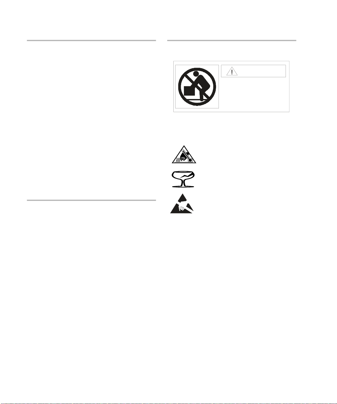
Safety Notices
Warning
Weight Exceeds 100 lbs. (45 kg.)
Do NOT lift unassisted. Use
a lift device or two people.
To protect against personal injury and product
damage, do not attempt to lift the product without
the assistance of another person or lift device.
Components bearing this symbol may
be hot to touch.
Components bearing this symbol are
fragile. Handle wit h care.
Components bearing this symbol are
susceptible to damage by static
electricity. ESD pr ec autions are
required.
Service
Any servicing, adjustment, maintenance, or repair
must be performed only by authorized servicetrained personnel.
2
Page 3

Format Conventions
Denotes
WARNING
Caution A hazard that can cause hardware or software damage
Note Significant concepts or operating instructions
this font
this font Text displayed on the screen
A hazard that can cause personal injury
Text to be typed verbatim: all commands, path names, file names, and directory names
Printing History
1st Edition - September 1999
2nd Edition - October 1999
3rd Edition - February 2000
4th Edition - July 2000
5th Edition - September 2000
6th Edition - October 2000
7th Edition - Decemb er 2000
3
Page 4

Manual Revision History
December 2000
Change Page
Added Figure 87 to clarify operation of the write cache flush thresholds. 253
Added note regarding t he impact of LUN binding on performance. 250
Added information on Managing the Universal Transport Mechanism (UTM). 298
Added information on major event logging available with firmware HP08. 307
Added Allocating Space for Disk Array Logs section describing use of
environment variable
Added information on Purging Controller Logs. 311
Added information for RAID 0 support on HP-UX. 47
Changed the required m inimu m numb er of disk module s per encl osure fro m
2 to 4 based on power supply requirements for the disk enclosure.
AM60_MAX_LOG_SIZE_MB.
308
73
4
Page 5

About This Book
This guide is intended for use by syst em administrators and others involved in operating and
managing the HP SureStore E Disk Array FC60. It is organized into the following chapters and
section.
Chapter 1, Product Description
Chapter 2, Topology and Array Planning
Chapter 3, Installation
Chapter 4, Managing the Disk Array on
HP-UX
Chapter 5, HP-UX Diagnostic Tools
Chapter 6, Troubleshooting
Chapter 7, Removal and Replacement
Chapter 8, Reference / Legal /
Regulatory
GLOSSARY
Index
Describes the feat ures, controls , and operati on of the
disk array.
Guidelines for designing the disk array configura tion
that best meets your needs.
Instruction for moving the disk array.
Complete instructions for managing your disk array
using the available management software.
Information on using STM to gather in formation abou t
disk array s tatus.
Instructions for isolating and solving common
problems that may occur during disk array operation.
Instructions for removing and replacing all customer-
replaceable components.
Regulatory, environmental, and other reference
information.
5
Page 6

Related Documents and Information
The following items co ntain information related t o the installation and use of the HP SureStore E
Disk Array and its management software.
HP SureStore E Disk Array FC60 Advanced User’s Guide -
•
book you are reading. Topics that a re discu ssed in m ore d etail i n the Ad vanc ed User’ s Gui de are
clearly identified throughout this book.
Download: www.hp.com/support/fc60
"
!
HP Storage Manager 60 User’s Guide
•
disk array management software for Windows NT and Windows 2000. It is included with the
A5628A software kit.
Download: www.hp.com/support/fc60
"
!
HP Storage Manager 60 Introd uction Guide
•
software for Windows NT and Windows 2000. It is included in electronic format on the
Storage Manager 60 CD
Download: www.hp.com/support/fc60
"
!
Fibre Channel Mass Storage Adapters Service and User Manual
•
Fibre Channel Mass Storage/9000. It describes installation of the Fibre Channel I/O adaptors into
K-, D-, T-, and V-class systems.
Download: www.hp.com/essd/efc/A3636A_documentation.html
"
!
Using EMS HA Monitors
•
used for hardware monitoring.
Download: http://www.docs.hp.com/hpux/ha/
"
!
.
(B5735-90001) - contains information about the EMS environment
- this guide describes the features and operation of the
- this guide introd uces the disk arr ay managem ent
this is the expanded version of the
(A3636-90002) - describes
HP
EMS Hardware Monitors User’s Guide
•
protect your system fro m undetected failures.
Download: http://www.docs.hp.com/hpux/systems/
"
!
Diagnostic/IPR Media User’s Guide
•
enabling the E M S Hardware Event Monitors.
Download: http://www.docs.hp.com/hpux/systems/
"
!
Managing MC/ServiceGuard
•
dependencies for hardwa re resources.
Download: http://www.docs.hp.com/hpux/ha/
"
!
6
(B3939-90024) - provides information on creating package
- describes how to use the EMS Hardware Monitors to
(B6191-90015) - provides information on using STM, and
Page 7

1 Product Description
Product Description . . . . . . . . . . . . . . . . . . . . . . . . . . . . . . . . . . . . . . . . . . . . . . . . . . . .18
Operating System Support. . . . . . . . . . . . . . . . . . . . . . . . . . . . . . . . . . . . . . . . . . . .20
Management Tools . . . . . . . . . . . . . . . . . . . . . . . . . . . . . . . . . . . . . . . . . . . . . . . . . .20
Features . . . . . . . . . . . . . . . . . . . . . . . . . . . . . . . . . . . . . . . . . . . . . . . . . . . . . . . . . . .20
High Availability . . . . . . . . . . . . . . . . . . . . . . . . . . . . . . . . . . . . . . . . . . . . . . . . . . . .21
Scalable Storage Capacity . . . . . . . . . . . . . . . . . . . . . . . . . . . . . . . . . . . . . . . . . . . .21
LED Status Monitoring. . . . . . . . . . . . . . . . . . . . . . . . . . . . . . . . . . . . . . . . . . . . . . .22
EMS Hardware Event Monitoring (HP-UX Only) . . . . . . . . . . . . . . . . . . . . . . . . .22
Disk Enclosure Components. . . . . . . . . . . . . . . . . . . . . . . . . . . . . . . . . . . . . . . . . . . . .23
Operation Features. . . . . . . . . . . . . . . . . . . . . . . . . . . . . . . . . . . . . . . . . . . . . . . . . .25
Disk Enclosure SC10 Modules. . . . . . . . . . . . . . . . . . . . . . . . . . . . . . . . . . . . . . . . .27
Array Controller Enclosure Components . . . . . . . . . . . . . . . . . . . . . . . . . . . . . . . . . .34
Front Cover . . . . . . . . . . . . . . . . . . . . . . . . . . . . . . . . . . . . . . . . . . . . . . . . . . . . . . . .37
Controller Modules. . . . . . . . . . . . . . . . . . . . . . . . . . . . . . . . . . . . . . . . . . . . . . . . . .38
Controller Fan Modules . . . . . . . . . . . . . . . . . . . . . . . . . . . . . . . . . . . . . . . . . . . . . .40
Power Supply Modules. . . . . . . . . . . . . . . . . . . . . . . . . . . . . . . . . . . . . . . . . . . . . . .42
Power Supply Fan Module . . . . . . . . . . . . . . . . . . . . . . . . . . . . . . . . . . . . . . . . . . .43
Battery Backup Unit . . . . . . . . . . . . . . . . . . . . . . . . . . . . . . . . . . . . . . . . . . . . . . . . .45
Disk Array High Availability Features . . . . . . . . . . . . . . . . . . . . . . . . . . . . . . . . . . . .47
RAID Technology . . . . . . . . . . . . . . . . . . . . . . . . . . . . . . . . . . . . . . . . . . . . . . . . . . .47
Disk Mirroring . . . . . . . . . . . . . . . . . . . . . . . . . . . . . . . . . . . . . . . . . . . . . . . . . . . . . .47
Data Parity . . . . . . . . . . . . . . . . . . . . . . . . . . . . . . . . . . . . . . . . . . . . . . . . . . . . . . . . .48
Data Striping . . . . . . . . . . . . . . . . . . . . . . . . . . . . . . . . . . . . . . . . . . . . . . . . . . . . . . .49
RAID Levels . . . . . . . . . . . . . . . . . . . . . . . . . . . . . . . . . . . . . . . . . . . . . . . . . . . . . . . .50
RAID Level Comparisons. . . . . . . . . . . . . . . . . . . . . . . . . . . . . . . . . . . . . . . . . . . . .57
Global Hot Spare Disks . . . . . . . . . . . . . . . . . . . . . . . . . . . . . . . . . . . . . . . . . . . . . . 61
Primary and Alternate I/O Paths . . . . . . . . . . . . . . . . . . . . . . . . . . . . . . . . . . . . . . .64
Capacity Management Features . . . . . . . . . . . . . . . . . . . . . . . . . . . . . . . . . . . . . . . . . .65
LUNs . . . . . . . . . . . . . . . . . . . . . . . . . . . . . . . . . . . . . . . . . . . . . . . . . . . . . . . . . . . . . .65
Contents
7
Page 8

Disk Groups. . . . . . . . . . . . . . . . . . . . . . . . . . . . . . . . . . . . . . . . . . . . . . . . . . . . . . . .65
Disk Array Caching. . . . . . . . . . . . . . . . . . . . . . . . . . . . . . . . . . . . . . . . . . . . . . . . . .66
Dynamic Capacity Expansion . . . . . . . . . . . . . . . . . . . . . . . . . . . . . . . . . . . . . . . .67
2 Topology and Array Planning
Overview . . . . . . . . . . . . . . . . . . . . . . . . . . . . . . . . . . . . . . . . . . . . . . . . . . . . . . . . . . . . .70
Array Design Considerations. . . . . . . . . . . . . . . . . . . . . . . . . . . . . . . . . . . . . . . . . . . . .71
Array Hardware Configuration . . . . . . . . . . . . . . . . . . . . . . . . . . . . . . . . . . . . . . . .71
RAID, LUNs, and Global Hot Spares . . . . . . . . . . . . . . . . . . . . . . . . . . . . . . . . . . .72
High Availability . . . . . . . . . . . . . . . . . . . . . . . . . . . . . . . . . . . . . . . . . . . . . . . . . . . .72
Performance . . . . . . . . . . . . . . . . . . . . . . . . . . . . . . . . . . . . . . . . . . . . . . . . . . . . . . .73
Storage Capacity. . . . . . . . . . . . . . . . . . . . . . . . . . . . . . . . . . . . . . . . . . . . . . . . . . . .75
Expanding Storage Capacity . . . . . . . . . . . . . . . . . . . . . . . . . . . . . . . . . . . . . . . . .75
Recommended Disk Array Configurations . . . . . . . . . . . . . . . . . . . . . . . . . . . . . . . . .77
Configuration Considerations . . . . . . . . . . . . . . . . . . . . . . . . . . . . . . . . . . . . . . . . .77
One Disk Enclosure Configuration. . . . . . . . . . . . . . . . . . . . . . . . . . . . . . . . . . . . .78
Two Disk Enclosure Configurations . . . . . . . . . . . . . . . . . . . . . . . . . . . . . . . . . . .80
Three Disk Enclosure Configurations . . . . . . . . . . . . . . . . . . . . . . . . . . . . . . . . . .84
Four Disk Enclosure Configurations . . . . . . . . . . . . . . . . . . . . . . . . . . . . . . . . . . .88
Five Disk Enclosure Configurations. . . . . . . . . . . . . . . . . . . . . . . . . . . . . . . . . . . .92
Six Disk Enclosure Configurations. . . . . . . . . . . . . . . . . . . . . . . . . . . . . . . . . . . . .96
Total Disk Array Capacity . . . . . . . . . . . . . . . . . . . . . . . . . . . . . . . . . . . . . . . . . . .100
For high-availability, one disk per SCSI channel is used as a global hot spare.. . 101
Topologies for HP-UX . . . . . . . . . . . . . . . . . . . . . . . . . . . . . . . . . . . . . . . . . . . . . . . . .102
Basic Topology . . . . . . . . . . . . . . . . . . . . . . . . . . . . . . . . . . . . . . . . . . . . . . . . . . . .103
Single-System Distance Topology. . . . . . . . . . . . . . . . . . . . . . . . . . . . . . . . . . . . .110
High Availability Topology. . . . . . . . . . . . . . . . . . . . . . . . . . . . . . . . . . . . . . . . . . .115
High Availability, Distance, and Capacity Topology . . . . . . . . . . . . . . . . . . . . .120
Campus Topology . . . . . . . . . . . . . . . . . . . . . . . . . . . . . . . . . . . . . . . . . . . . . . . . . .125
Performance Topology with Switches . . . . . . . . . . . . . . . . . . . . . . . . . . . . . . . . .129
Topologies for Windows NT and Windows 2000 . . . . . . . . . . . . . . . . . . . . . . . . . . .131
8
Page 9

Non-High Availability Topologies . . . . . . . . . . . . . . . . . . . . . . . . . . . . . . . . . . . . .133
High Availability Topologies . . . . . . . . . . . . . . . . . . . . . . . . . . . . . . . . . . . . . . . . .137
3Installation
Overview . . . . . . . . . . . . . . . . . . . . . . . . . . . . . . . . . . . . . . . . . . . . . . . . . . . . . . . . . . . .144
Host System Requirements . . . . . . . . . . . . . . . . . . . . . . . . . . . . . . . . . . . . . . . . . . . . .145
HP-UX. . . . . . . . . . . . . . . . . . . . . . . . . . . . . . . . . . . . . . . . . . . . . . . . . . . . . . . . . . . .1 45
Windows NT and Windows 2000. . . . . . . . . . . . . . . . . . . . . . . . . . . . . . . . . . . . . .146
Site Requirements. . . . . . . . . . . . . . . . . . . . . . . . . . . . . . . . . . . . . . . . . . . . . . . . . . . . .147
Environmental Requirements . . . . . . . . . . . . . . . . . . . . . . . . . . . . . . . . . . . . . . . .147
Electrical Requirements. . . . . . . . . . . . . . . . . . . . . . . . . . . . . . . . . . . . . . . . . . . . .147
Power Distribution Units (PDU/PDRU). . . . . . . . . . . . . . . . . . . . . . . . . . . . . . . . . . .150
Installing PDUs . . . . . . . . . . . . . . . . . . . . . . . . . . . . . . . . . . . . . . . . . . . . . . . . . . . .152
Recommended UPS Models. . . . . . . . . . . . . . . . . . . . . . . . . . . . . . . . . . . . . . . . . .152
Installing the Disk Array FC60 . . . . . . . . . . . . . . . . . . . . . . . . . . . . . . . . . . . . . . . . . .155
Installing the Disk Enclosures. . . . . . . . . . . . . . . . . . . . . . . . . . . . . . . . . . . . . . . . . . . 1 60
Step 1: Collect Required Tools . . . . . . . . . . . . . . . . . . . . . . . . . . . . . . . . . . . . . . .160
Step 2: Unpack the Product . . . . . . . . . . . . . . . . . . . . . . . . . . . . . . . . . . . . . . . . . .160
Step 3: Install Mounting Rails . . . . . . . . . . . . . . . . . . . . . . . . . . . . . . . . . . . . . . . .162
Step 4: Install the Disk Enclosure. . . . . . . . . . . . . . . . . . . . . . . . . . . . . . . . . . . . .162
Step 5: Install Disks and Fillers. . . . . . . . . . . . . . . . . . . . . . . . . . . . . . . . . . . . . . .1 66
Moving a Disk Enclosure from One Disk Array to Another . . . . . . . . . . . . . . .168
Installing the Controller. . . . . . . . . . . . . . . . . . . . . . . . . . . . . . . . . . . . . . . . . . . . . . . .170
Step 1: Gather Required Tools. . . . . . . . . . . . . . . . . . . . . . . . . . . . . . . . . . . . . . . .170
Step 2: Unpack the Product . . . . . . . . . . . . . . . . . . . . . . . . . . . . . . . . . . . . . . . . . .170
Step 3: Install Mounting Rails . . . . . . . . . . . . . . . . . . . . . . . . . . . . . . . . . . . . . . . .173
Step 4: Install the Controller Enclosure. . . . . . . . . . . . . . . . . . . . . . . . . . . . . . . .173
Configuration Switches . . . . . . . . . . . . . . . . . . . . . . . . . . . . . . . . . . . . . . . . . . . . . . . .176
Disk Enclosure (Tray) ID Switch . . . . . . . . . . . . . . . . . . . . . . . . . . . . . . . . . . . . .176
Disk Enclosure DIP Switch . . . . . . . . . . . . . . . . . . . . . . . . . . . . . . . . . . . . . . . . . .176
Fibre Channel Host ID Address Setting . . . . . . . . . . . . . . . . . . . . . . . . . . . . . . . .179
Contents
9
Page 10

Attaching Power Cords . . . . . . . . . . . . . . . . . . . . . . . . . . . . . . . . . . . . . . . . . . . . . . . .183
Attaching SCSI Cables and
Configuring the Disk Enclosure Switches. . . . . . . . . . . . . . . . . . . . . . . . . . . . . . . . .187
Full-Bus Cabling and Switch Configuration . . . . . . . . . . . . . . . . . . . . . . . . . . . .188
Split-Bus Switch and Cabling Configurations . . . . . . . . . . . . . . . . . . . . . . . . . . .191
Connecting the Fibre Channel Cables . . . . . . . . . . . . . . . . . . . . . . . . . . . . . . . . . . . .196
Applying Power to the Disk Array . . . . . . . . . . . . . . . . . . . . . . . . . . . . . . . . . . . . . . .198
Verifying Disk Array Connection . . . . . . . . . . . . . . . . . . . . . . . . . . . . . . . . . . . . . . . .206
On Windows NT and Windows 2000. . . . . . . . . . . . . . . . . . . . . . . . . . . . . . . . . . .206
On HP-UX. . . . . . . . . . . . . . . . . . . . . . . . . . . . . . . . . . . . . . . . . . . . . . . . . . . . . . . . .206
Interpreting Hardware Paths. . . . . . . . . . . . . . . . . . . . . . . . . . . . . . . . . . . . . . . . .208
Installing the Disk Array FC60 Software (HP-UX Only) . . . . . . . . . . . . . . . . . . . . .213
System Requirements. . . . . . . . . . . . . . . . . . . . . . . . . . . . . . . . . . . . . . . . . . . . . . .213
Verifying the Operating System. . . . . . . . . . . . . . . . . . . . . . . . . . . . . . . . . . . . . . .214
Installing the Disk Array FC60 Software . . . . . . . . . . . . . . . . . . . . . . . . . . . . . . .214
Downgrading the Disk Array Firmware for HP-UX 11.11 Hosts. . . . . . . . . . . .215
Configuring the Disk Array . . . . . . . . . . . . . . . . . . . . . . . . . . . . . . . . . . . . . . . . . . . .216
HP-UX. . . . . . . . . . . . . . . . . . . . . . . . . . . . . . . . . . . . . . . . . . . . . . . . . . . . . . . . . . . .216
Windows NT and Windows 2000. . . . . . . . . . . . . . . . . . . . . . . . . . . . . . . . . . . . . .220
Using the Disk Array FC60 as a Boot Device (HP-UX Only). . . . . . . . . . . . . . . . . .222
Solving Common Installation Problems . . . . . . . . . . . . . . . . . . . . . . . . . . . . . . . . . .223
Adding Disk Enclosures to Increase Capacity . . . . . . . . . . . . . . . . . . . . . . . . . . . . .224
General Rules for Adding Disk Enclosures to the Disk Array . . . . . . . . . . . . .224
Step 1. Plan the Expanded Configuration . . . . . . . . . . . . . . . . . . . . . . . . . . . . . .225
Step 2. Backup All Disk Array Data . . . . . . . . . . . . . . . . . . . . . . . . . . . . . . . . . . .226
Step 3. Prepare the Disk Array for Shut Down . . . . . . . . . . . . . . . . . . . . . . . . . .226
Step 4. Add the New Disk Enclosures . . . . . . . . . . . . . . . . . . . . . . . . . . . . . . . . .227
Step 5. Completing the Expansion . . . . . . . . . . . . . . . . . . . . . . . . . . . . . . . . . . . .230
Capacity Expansion Example . . . . . . . . . . . . . . . . . . . . . . . . . . . . . . . . . . . . . . . .232
10
Page 11

4 Managing the Disk Array on HP-UX
Tools for Managing the Disk Array FC60. . . . . . . . . . . . . . . . . . . . . . . . . . . . . . . . . .238
System Administration Manager (SAM). . . . . . . . . . . . . . . . . . . . . . . . . . . . . . . .238
Array Manager 60 . . . . . . . . . . . . . . . . . . . . . . . . . . . . . . . . . . . . . . . . . . . . . . . . . .238
STM. . . . . . . . . . . . . . . . . . . . . . . . . . . . . . . . . . . . . . . . . . . . . . . . . . . . . . . . . . . . . .238
Installing the Array Manager 60 Software . . . . . . . . . . . . . . . . . . . . . . . . . . . . . . . . .240
AM60Srvr Daemon . . . . . . . . . . . . . . . . . . . . . . . . . . . . . . . . . . . . . . . . . . . . . . . . .241
Running Array Manager 60. . . . . . . . . . . . . . . . . . . . . . . . . . . . . . . . . . . . . . . . . . .241
Managing Disk Array Capacity . . . . . . . . . . . . . . . . . . . . . . . . . . . . . . . . . . . . . . . . . . 2 42
Configuring LUNs . . . . . . . . . . . . . . . . . . . . . . . . . . . . . . . . . . . . . . . . . . . . . . . . . .242
Selecting Disks for a LUN . . . . . . . . . . . . . . . . . . . . . . . . . . . . . . . . . . . . . . . . . . .243
Assigning LUN Ownership . . . . . . . . . . . . . . . . . . . . . . . . . . . . . . . . . . . . . . .247
Selecting a RAID Level . . . . . . . . . . . . . . . . . . . . . . . . . . . . . . . . . . . . . . . . . .247
Global Hot Spares . . . . . . . . . . . . . . . . . . . . . . . . . . . . . . . . . . . . . . . . . . . . . . . . . .248
Setting Stripe Segment Size . . . . . . . . . . . . . . . . . . . . . . . . . . . . . . . . . . . . . .2 49
Evaluating Performance Impact . . . . . . . . . . . . . . . . . . . . . . . . . . . . . . . . . . . . . .250
Adding Capacity to the Disk Array. . . . . . . . . . . . . . . . . . . . . . . . . . . . . . . . . . . . . . .254
Adding More Disk Modules . . . . . . . . . . . . . . . . . . . . . . . . . . . . . . . . . . . . . . . . . .2 54
Adding Additional Disk Enclosures . . . . . . . . . . . . . . . . . . . . . . . . . . . . . . . . . . .256
Replacing Disk Modules with Higher Capacity Modules. . . . . . . . . . . . . . . . . .256
Upgrading Controller Cache to 512 Mbytes. . . . . . . . . . . . . . . . . . . . . . . . . . . . . . .258
Managing the Disk Array Using SAM . . . . . . . . . . . . . . . . . . . . . . . . . . . . . . . . . . . . .2 60
Checking Disk Array Status. . . . . . . . . . . . . . . . . . . . . . . . . . . . . . . . . . . . . . . . . .261
Assigning an Alias to the Disk Array. . . . . . . . . . . . . . . . . . . . . . . . . . . . . . . . . . .264
Locating Disk Modules. . . . . . . . . . . . . . . . . . . . . . . . . . . . . . . . . . . . . . . . . . . . . .265
Binding a LUN . . . . . . . . . . . . . . . . . . . . . . . . . . . . . . . . . . . . . . . . . . . . . . . . . . . . .267
Unbinding a LUN. . . . . . . . . . . . . . . . . . . . . . . . . . . . . . . . . . . . . . . . . . . . . . . . . . .271
Replacing a LUN . . . . . . . . . . . . . . . . . . . . . . . . . . . . . . . . . . . . . . . . . . . . . . . . . . .271
Adding a Global Hot Spare. . . . . . . . . . . . . . . . . . . . . . . . . . . . . . . . . . . . . . . . . . .273
Removing a Global Hot Spare . . . . . . . . . . . . . . . . . . . . . . . . . . . . . . . . . . . . . . . .275
Contents
11
Page 12

Managing the Disk Array Using Array Manager 60. . . . . . . . . . . . . . . . . . . . . . . . . .276
Command Syntax Conventions. . . . . . . . . . . . . . . . . . . . . . . . . . . . . . . . . . . . . . .279
Array Manager 60 man pages. . . . . . . . . . . . . . . . . . . . . . . . . . . . . . . . . . . . . . . . .279
Quick Help . . . . . . . . . . . . . . . . . . . . . . . . . . . . . . . . . . . . . . . . . . . . . . . . . . . . . . . .279
Selecting a Disk Array and Its Components . . . . . . . . . . . . . . . . . . . . . . . . . . . .280
Preparing to Manage the Disk Array . . . . . . . . . . . . . . . . . . . . . . . . . . . . . . . . . .281
Checking Disk Array Status. . . . . . . . . . . . . . . . . . . . . . . . . . . . . . . . . . . . . . . . . .282
Managing LUNs. . . . . . . . . . . . . . . . . . . . . . . . . . . . . . . . . . . . . . . . . . . . . . . . . . . .289
Managing Global Hot Spares. . . . . . . . . . . . . . . . . . . . . . . . . . . . . . . . . . . . . . . . .295
Managing Disk Array Configuration. . . . . . . . . . . . . . . . . . . . . . . . . . . . . . . . . . .297
Managing the Universal Transport Mechanism (UTM) . . . . . . . . . . . . . . . . . . .298
Managing Cache Parameters. . . . . . . . . . . . . . . . . . . . . . . . . . . . . . . . . . . . . . . . .299
Performing Disk Array Maintenance . . . . . . . . . . . . . . . . . . . . . . . . . . . . . . . . . .304
Managing Disk Array Logs. . . . . . . . . . . . . . . . . . . . . . . . . . . . . . . . . . . . . . . . . . .307
Upgrading Disk Firmware . . . . . . . . . . . . . . . . . . . . . . . . . . . . . . . . . . . . . . . . . . .313
Managing the Disk Array Using STM . . . . . . . . . . . . . . . . . . . . . . . . . . . . . . . . . . . . .314
Checking Disk Array Status Information. . . . . . . . . . . . . . . . . . . . . . . . . . . . . . .314
Binding a LUN . . . . . . . . . . . . . . . . . . . . . . . . . . . . . . . . . . . . . . . . . . . . . . . . . . . . .314
Unbinding a LUN. . . . . . . . . . . . . . . . . . . . . . . . . . . . . . . . . . . . . . . . . . . . . . . . . . .315
Adding a Global Hot Spare. . . . . . . . . . . . . . . . . . . . . . . . . . . . . . . . . . . . . . . . . . .315
Removing a Global Hot Spare . . . . . . . . . . . . . . . . . . . . . . . . . . . . . . . . . . . . . . . .3 15
Locating Disk Modules. . . . . . . . . . . . . . . . . . . . . . . . . . . . . . . . . . . . . . . . . . . . . .316
Status Conditions and Sense Code Information. . . . . . . . . . . . . . . . . . . . . . . . . . . .317
LUN Status Conditions. . . . . . . . . . . . . . . . . . . . . . . . . . . . . . . . . . . . . . . . . . . . . .317
Disk Status Conditions. . . . . . . . . . . . . . . . . . . . . . . . . . . . . . . . . . . . . . . . . . . . . .319
Component Status Conditions. . . . . . . . . . . . . . . . . . . . . . . . . . . . . . . . . . . . . . . .321
FRU Codes. . . . . . . . . . . . . . . . . . . . . . . . . . . . . . . . . . . . . . . . . . . . . . . . . . . . . . . .322
SCSI Sense Codes . . . . . . . . . . . . . . . . . . . . . . . . . . . . . . . . . . . . . . . . . . . . . . . . . .327
5 HP-UX Diagnostic Tools
Overview . . . . . . . . . . . . . . . . . . . . . . . . . . . . . . . . . . . . . . . . . . . . . . . . . . . . . . . . . . . .346
12
Page 13

Support Tools Manager . . . . . . . . . . . . . . . . . . . . . . . . . . . . . . . . . . . . . . . . . . . . . . . .347
STM User Interfaces . . . . . . . . . . . . . . . . . . . . . . . . . . . . . . . . . . . . . . . . . . . . . . . .347
STM Tools . . . . . . . . . . . . . . . . . . . . . . . . . . . . . . . . . . . . . . . . . . . . . . . . . . . . . . . .351
Using the STM Information Tool. . . . . . . . . . . . . . . . . . . . . . . . . . . . . . . . . . . . . .352
Interpreting the Information Tool Information Log . . . . . . . . . . . . . . . . . . . . . .354
Interpreting the Information Tool Activity Log. . . . . . . . . . . . . . . . . . . . . . . . . .354
Using the STM Expert Tool . . . . . . . . . . . . . . . . . . . . . . . . . . . . . . . . . . . . . . . . . .355
6 Troubleshooting
Introduction. . . . . . . . . . . . . . . . . . . . . . . . . . . . . . . . . . . . . . . . . . . . . . . . . . . . . . . . . .360
About Field Replaceable Units (FRUs) . . . . . . . . . . . . . . . . . . . . . . . . . . . . . . . .361
HP-UX Troubleshooting Tools. . . . . . . . . . . . . . . . . . . . . . . . . . . . . . . . . . . . . . . .362
Windows NT and Windows 2000 Troubleshooting Tools . . . . . . . . . . . . . . . . .362
EMS Hardware Event Monitoring (HP-UX Only) . . . . . . . . . . . . . . . . . . . . . . . .362
Disk Array Installation/Troubleshooting Checklist . . . . . . . . . . . . . . . . . . . . . . . . . 365
Power-Up Troubleshooting . . . . . . . . . . . . . . . . . . . . . . . . . . . . . . . . . . . . . . . . . . . . .366
Controller Enclosure Troubleshooting . . . . . . . . . . . . . . . . . . . . . . . . . . . . . . . . . . .367
Introduction. . . . . . . . . . . . . . . . . . . . . . . . . . . . . . . . . . . . . . . . . . . . . . . . . . . . . . .367
Controller Enclosure LEDs . . . . . . . . . . . . . . . . . . . . . . . . . . . . . . . . . . . . . . . . . .368
Master Troubleshooting Table. . . . . . . . . . . . . . . . . . . . . . . . . . . . . . . . . . . . . . . .370
SureStore E Disk System SC10 Troubleshooting . . . . . . . . . . . . . . . . . . . . . . . . . . .376
Disk Enclosure LEDs . . . . . . . . . . . . . . . . . . . . . . . . . . . . . . . . . . . . . . . . . . . . . . .376
Losing LUN 0 . . . . . . . . . . . . . . . . . . . . . . . . . . . . . . . . . . . . . . . . . . . . . . . . . . . . . .376
Interpreting Component Status Values (HP-UX Only). . . . . . . . . . . . . . . . . . . .379
Isolating Causes. . . . . . . . . . . . . . . . . . . . . . . . . . . . . . . . . . . . . . . . . . . . . . . . . . . .380
Contents
7 Removal and Replacement
Overview . . . . . . . . . . . . . . . . . . . . . . . . . . . . . . . . . . . . . . . . . . . . . . . . . . . . . . . . . . . .384
Disk Enclosure Modules . . . . . . . . . . . . . . . . . . . . . . . . . . . . . . . . . . . . . . . . . . . . . . .386
Disk Module or Filler Module . . . . . . . . . . . . . . . . . . . . . . . . . . . . . . . . . . . . . . .386
13
Page 14

Disk Enclosure Fan Module . . . . . . . . . . . . . . . . . . . . . . . . . . . . . . . . . . . . . . . . .392
Disk Enclosure Power Supply Module . . . . . . . . . . . . . . . . . . . . . . . . . . . . . . . .394
Controller Enclosure Modules . . . . . . . . . . . . . . . . . . . . . . . . . . . . . . . . . . . . . . . . . .396
Front Cover Removal/Replacement . . . . . . . . . . . . . . . . . . . . . . . . . . . . . . . . . .397
Controller Fan Module . . . . . . . . . . . . . . . . . . . . . . . . . . . . . . . . . . . . . . . . . . . . .398
Battery Backup Unit (BBU) Removal/Replacement. . . . . . . . . . . . . . . . . . . . . .400
Power Supply Fan Module Removal/Replacement. . . . . . . . . . . . . . . . . . . . . . .403
Power Supply Module Removal/Replacement . . . . . . . . . . . . . . . . . . . . . . . . . .405
SCSI Cables . . . . . . . . . . . . . . . . . . . . . . . . . . . . . . . . . . . . . . . . . . . . . . . . . . . . . . .407
8 Reference / Legal / Regulatory
System Requirements. . . . . . . . . . . . . . . . . . . . . . . . . . . . . . . . . . . . . . . . . . . . . . . . . .410
Host Systems . . . . . . . . . . . . . . . . . . . . . . . . . . . . . . . . . . . . . . . . . . . . . . . . . . . . . .410
Supported Operating Systems. . . . . . . . . . . . . . . . . . . . . . . . . . . . . . . . . . . . . . . .410
Fibre Channel Host Adapters . . . . . . . . . . . . . . . . . . . . . . . . . . . . . . . . . . . . . . . .411
Models and Options . . . . . . . . . . . . . . . . . . . . . . . . . . . . . . . . . . . . . . . . . . . . . . . . . . .412
A5277A/AZ Controller Enclosure Models and Options . . . . . . . . . . . . . . . . . . .412
A5294A/AZ Disk Enclosure SC10 Models and Options . . . . . . . . . . . . . . . . . . .414
Disk Array FC60 Upgrade and Add-On Products . . . . . . . . . . . . . . . . . . . . . . . .416
PDU/PDRU Products . . . . . . . . . . . . . . . . . . . . . . . . . . . . . . . . . . . . . . . . . . . . . . . . . .417
Replaceable Parts. . . . . . . . . . . . . . . . . . . . . . . . . . . . . . . . . . . . . . . . . . . . . . . . . . . . .418
A5277A/AZ Controller Enclosure Specifications . . . . . . . . . . . . . . . . . . . . . . . . . . .420
Dimensions: . . . . . . . . . . . . . . . . . . . . . . . . . . . . . . . . . . . . . . . . . . . . . . . . . . . . . .420
Weight: . . . . . . . . . . . . . . . . . . . . . . . . . . . . . . . . . . . . . . . . . . . . . . . . . . . . . . . . .420
AC Power: . . . . . . . . . . . . . . . . . . . . . . . . . . . . . . . . . . . . . . . . . . . . . . . . . . . . . . . .421
Heat Output: . . . . . . . . . . . . . . . . . . . . . . . . . . . . . . . . . . . . . . . . . . . . . . . . . . . . . .421
Environmental Specifications . . . . . . . . . . . . . . . . . . . . . . . . . . . . . . . . . . . . . . . .422
Acoustics . . . . . . . . . . . . . . . . . . . . . . . . . . . . . . . . . . . . . . . . . . . . . . . . . . . . . . . . .423
A5294A/AZ Disk Enclosure Specifications . . . . . . . . . . . . . . . . . . . . . . . . . . . . . . . .424
Dimensions: . . . . . . . . . . . . . . . . . . . . . . . . . . . . . . . . . . . . . . . . . . . . . . . . . . . . . .424
Weight: . . . . . . . . . . . . . . . . . . . . . . . . . . . . . . . . . . . . . . . . . . . . . . . . . . . . . . . . . .424
14
Page 15

AC Power:. . . . . . . . . . . . . . . . . . . . . . . . . . . . . . . . . . . . . . . . . . . . . . . . . . . . . . . . .425
DC Power Output:. . . . . . . . . . . . . . . . . . . . . . . . . . . . . . . . . . . . . . . . . . . . . . . . . .425
Heat Output:. . . . . . . . . . . . . . . . . . . . . . . . . . . . . . . . . . . . . . . . . . . . . . . . . . . . . . . 4 25
Environmental Specifications . . . . . . . . . . . . . . . . . . . . . . . . . . . . . . . . . . . . . . . .426
Acoustics . . . . . . . . . . . . . . . . . . . . . . . . . . . . . . . . . . . . . . . . . . . . . . . . . . . . . . . . .427
Warranty and License Information. . . . . . . . . . . . . . . . . . . . . . . . . . . . . . . . . . . . . . .428
Hewlett-Packard Hardware Limited Warranty . . . . . . . . . . . . . . . . . . . . . . . . . .428
Software Product Limited Warranty. . . . . . . . . . . . . . . . . . . . . . . . . . . . . . . . . . .429
Limitation of Warranty . . . . . . . . . . . . . . . . . . . . . . . . . . . . . . . . . . . . . . . . . . . . . .429
Hewlett-Packard Software License Terms. . . . . . . . . . . . . . . . . . . . . . . . . . . . . .431
Regulatory Compliance. . . . . . . . . . . . . . . . . . . . . . . . . . . . . . . . . . . . . . . . . . . . . . . .434
Safety Certifications:. . . . . . . . . . . . . . . . . . . . . . . . . . . . . . . . . . . . . . . . . . . . . . . .434
EMC Compliance. . . . . . . . . . . . . . . . . . . . . . . . . . . . . . . . . . . . . . . . . . . . . . . . . . .434
FCC Statements (USA Only) . . . . . . . . . . . . . . . . . . . . . . . . . . . . . . . . . . . . . . . . . . . .435
IEC Statement (Worldwide). . . . . . . . . . . . . . . . . . . . . . . . . . . . . . . . . . . . . . . . . .435
CSA Statement (For Canada Only). . . . . . . . . . . . . . . . . . . . . . . . . . . . . . . . . . . .435
VCCI Statement (Japan). . . . . . . . . . . . . . . . . . . . . . . . . . . . . . . . . . . . . . . . . . . . .436
Harmonics Conformance (Japan). . . . . . . . . . . . . . . . . . . . . . . . . . . . . . . . . . . . .436
Class A Warning Statement (Taiwan). . . . . . . . . . . . . . . . . . . . . . . . . . . . . . . . . .436
Spécification ATI Classe A (France Seulement). . . . . . . . . . . . . . . . . . . . . . . . .437
Product Noise Declaration (For Germany Only) . . . . . . . . . . . . . . . . . . . . . . . .437
Geräuschemission (For Germany Only) . . . . . . . . . . . . . . . . . . . . . . . . . . . . . . .438
Declaration of Conformity. . . . . . . . . . . . . . . . . . . . . . . . . . . . . . . . . . . . . . . . . . .439
Contents
15
Page 16

16
Page 17

1 PRODUCT DESCRIPTION
Product Description. . . . . . . . . . . . . . . . . . . . . . . . . . . . . . . . . . . . . . . . . . . . . . . . . . . . 18
Disk Enclosure Components . . . . . . . . . . . . . . . . . . . . . . . . . . . . . . . . . . . . . . . . . . . . 23
Array Controller Enclosure Components . . . . . . . . . . . . . . . . . . . . . . . . . . . . . . . . . . 34
Disk Array High Availability Features. . . . . . . . . . . . . . . . . . . . . . . . . . . . . . . . . . . . . . 47
Capacity Management Features . . . . . . . . . . . . . . . . . . . . . . . . . . . . . . . . . . . . . . . . . . 65
Product Description
17
Page 18

Product Description
The HP SureStore E Disk Array FC60 (Disk Array FC60) is a disk storage system that
features high data availability, high performance, and storage scalability. To provide high
availability, the Disk Array FC60 uses redundant, hot swappable modules, which can be
replaced without disrupting disk array operation should they fail.
The Disk Array FC60 consists of two primary compone nts: an FC60 controller enclosure,
and from one to six HP SureStore E Disk System SC10 enclosures (referred to throughout
this document as simply di sk enclosures). The controller enclosure is respo nsible for
providing overall control of the Disk Array FC60 by managing the communication between
the host and the disk enclosures. Host communication is done through dual Fibre Channel
arbitrated loops (whe n dual controller modules are installed). By using Fibre Ch annel, the
Disk Array FC60 achieves a high data rate throughput. High data throughput is maintained
to the disks by using u p to six Ultr a2 SCSI c hann els t o the disk en clos ures ( one ch anne l for
each disk enclosure).
In addition to increase d performance, the use of multiple disk enclosures provides
scalability — simplifying the process of adding storage capacity as needed. Up to six disk
enclosures can be added incrementally as storage demands increase. Each disk enclosure
holds up to ten disk modules in capacities of 9.1 Gbyte, 8.2 Gbyte, 36.4 Gbyte, or 73.4
Gbyte. A fully loaded syst em comprising six disk enclosures, each populated with ten 73.4Gbyte disk modules, achieves a capacity of over 3 Tbytes.
The Disk Array FC60 enclosures are designed for installation in HP’s original 19-inch
cabinets, which include the C2785A (1.1m), C2786A (1.6m), C2787A (2m), A1896A (1.1 m),
and A1897A (1.6 m) and the HP Rack System/E Racks which includes the A490xA and
A150xA Rack System/E cabinets. The Disk Array FC60 is also supported in the Rittal 9000
Series racks.
18 Product Description
Page 19
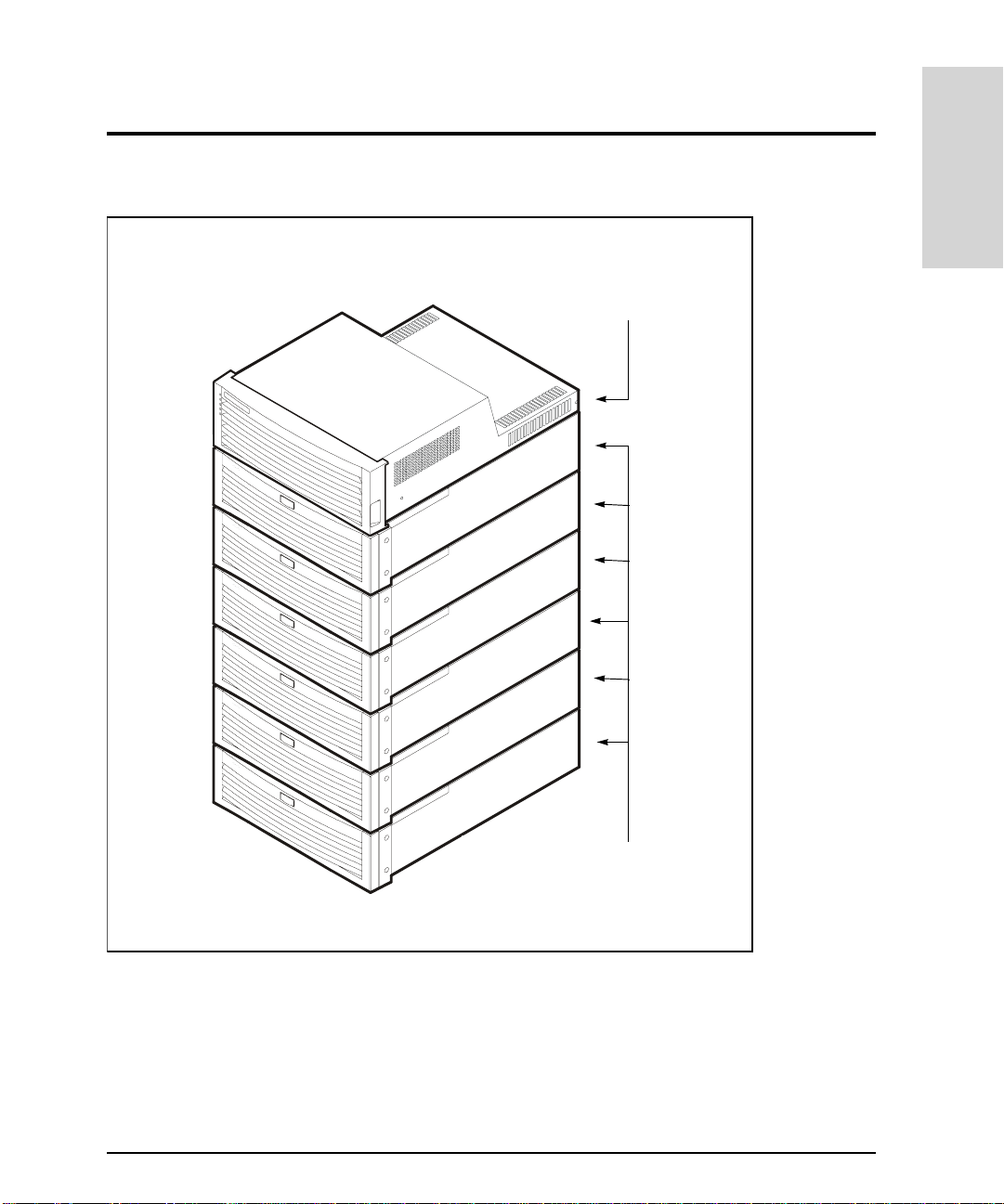
Array Controller FC60
Product Description
Figure 1
SureStore E
Disk System SC10
HP SureStore E Disk Arra y FC60 (Controller with Six Disk Enclosures)
Product Description 19
Page 20

Operating System Support
The Disk Array FC60 is currently supported on the followi ng operating systems:
HP-UX 11.0, 11.11, and 10.20
•
Windows NT 4.0
•
Windows 2000
•
Note
Some disk array featu res ar e specif ic to eac h op eratin g system. Th ese featu res
are clearly identifi ed throughout this book.
Management Tools
HP-UX Tools
The following tools are available for managing the disk array on HP-UX. These tools are
included with the disk array.
Array Manager 60 command line utilities
•
SAM
•
Support Tools Manager (STM)
•
Windows NT and Windows 2000
The following tools are used to manage the Disk Array FC60 on Windows NT and Windows
2000. This tool is not included with the disk array, but must be ordered separately as
product A5628A.
HP Storage Manager 60
•
(A5628A)
Features
The Disk Array FC60 offers the following fe atures
High availability
•
Scalable storage capacity
•
LED status monitoring
•
20 Product Description
Page 21

RAID levels 0, 1, 0/1, 3, and 5 ( RAID level 3 supported on Windows NT and Windows
•
2000 only)
EMS hardware monitoring (HP-UX only)
•
High Availability
High availability is a general term that describes hardware and software systems that are
designed to minimize system downtime — planned or unplanned. The Disk Array FC60
qualifies as high-availability hardware , achieving 99.99% availability.
The following features enable high availab ility:
Hot-swappable, high-capacity, high-speed disk modules
•
Dual Fibre Channel arbitrated loops (FC-AL) connection to the host
•
Redundant, hot-swappable, fans and power supplies
•
Support for RAID 1, 0/1, and 5
•
Remote monito ring and diagnosti c s
•
EMS Hardware event monitoring and real-time error reporting (HP-UX only)
•
Product Description
Note
The Disk Array FC60 is designed to operate with either one or two cont roller
modules; however, for data integrity and high availability it is highly
recommended th at dual controller modules be installed.
Scalable Storage Capacity
The Disk Array FC60 is designed to provide maxi mum scalability, simplifying the process
of adding storage capacity as required. Storage capacity can be added in three ways:
– By adding additional disk modules to a disk enclosure
– By adding additional disk enclosures to the array
– By replacing existing disk modules with higher capacity modules
The controller enclosure supports up t o six disk enclosures. Each disk enclos ure holds up
to ten disk modules in capacities of 9.1 Gbyte, 18.2 Gbyte, 36.4 Gbyte, or 73.4 Gbyte. The
minimum configuration for the array is one disk enclosure with two 9.1-Gbyte disk
modules. The maximum co nfiguration is six disk enclosures w ith ten 73.4-Gbyte disk
Product Description 21
Page 22

modules. This provi des a storage cap acity range from 36 Gbytes to over 3 Tbytes of usab le
storage.
LED Status Monitoring
Both the controller enclosure and disk enclosure monitor the status of their internal
components and operations. At least one LED is provided for each swappable module. If an
error is detected in any module, the error is displayed on the appropriate module’s LED.
This allows failed modules to be quickly ide nt if ied and replaced.
EMS Hardware Event Monitoring (HP-UX Only)
The Disk Array FC60 is fully supported by Hewlett-Packard's EMS Hardware Monitors,
which allow you to monitor all aspects of product operation and be alerted imme diately if
any failure or other unusua l event occurs. Hardware monitoring is available at no cost to
users running HP-UX 11.0 or 10.20.
Hardware monitoring provides a high level of protection against system hardware f ailure.
It provides an important tool for implementing a high-availability strategy for your system.
By using EMS Hardware Mo nitors, you can virtually eliminate undetected hardware
failures that could interrupt syst em operation or cause data loss.
The EMS Hardware Monito r software with the Disk Array FC60 monitor is distributed on
the
HP-UX Support Plus CD-ROM
installing and using hardware event monitoring is contained in the EMS Hardware
Monitors User's Guide (B6191-90011). A copy of this book can be accessed from the
Systems Hardware, Diagnostics, & Monitoring pa ge of Hewlett-Packard's on-line
documentation web site at http :/ /www.docs.hp.com/hpux/systems/
release 9912 and later. Complete inf ormation on
The minimum supported version of the Disk Array FC60 hardware monitor (fc60mon) is
A.01.04. To verify the version of the monitor installed, type:
what /usr/sbin/stm/uut/bin/tools/monitor/fc60mon
22 Product Description
Page 23

Disk Enclosure Components
The SureStore E Disk System SC10, or disk enclosure, is a high availability Ultra2 SCSI
storage product. It provides an LVD SCSI connection to the controller enclosur e and ten
slots on a single-ended backpla ne for high-speed, high-capacity LVD SCSI disks. Six disk
enclosures fully populated with 9.1 Gbtye disks provide 0.54 Tbytes of storage in a 2-meter
System/E rack. When fully populated with 73.4 Gbyte disks, the array provides over 3
Tbytes of storage. These values represent maximum storage; usable storage space will vary
depending on the RAID leve l used.
The disk enclosure consists of modular, redundant components that are e asy to upgrade
and maintain. See Figure 2. Disks, fans, power supplies, and Bus Control Cards (BCCs) are
replaceable parts that plug into individual slots in the front and back of the disk enclosure.
Redundant fans, power supplies, an d disk modules can be removed and replaced without
interrupting storage operations. In addition, a single disk within a LUN can be replaced
while the system is on.
Product Description
Disk Enclosure Components 23
Page 24
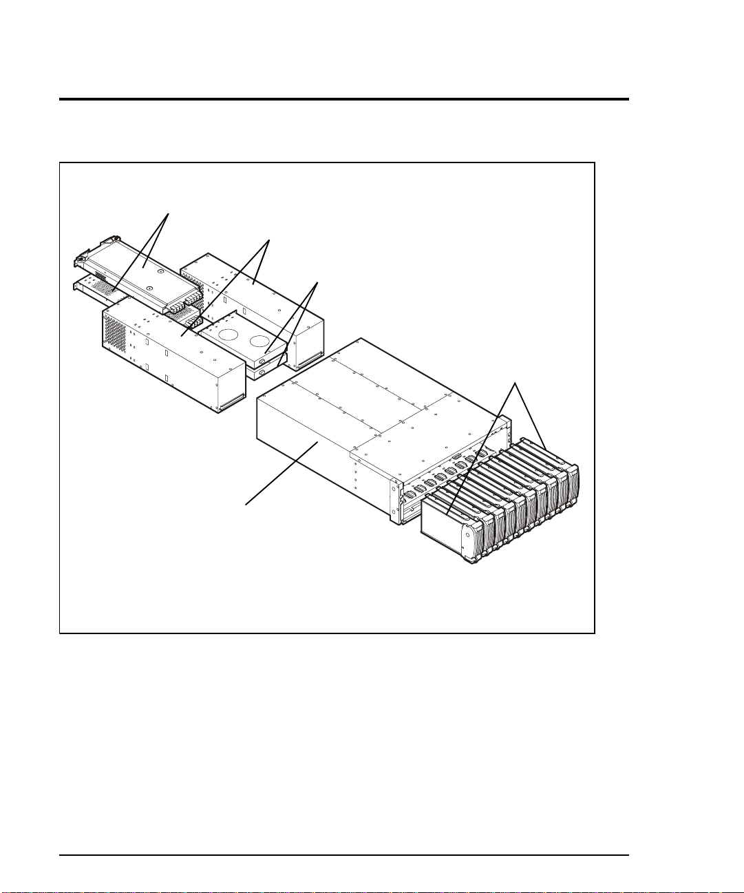
BCC Modules
Power Supply Modules
Fan Modules
Disk Modules
Chassis (and Backplane)
Figure 2
24 Disk Enclosure Components
Disk Enclosure Components, Exploded View
(Front Door Not Shown)
Page 25

Operation Features
The disk enclosure is designed to be installed in a standard 19-inch rack and occupies 3.5
EIA units (high). Disk drives mount in t he front of the enclosure. Also located in t he f ront
of the enclosure are a p ower switch and status LED s. A lockable fr ont door shields RFI and
restricts access to the disk drives and power button (Figure 3 on page 26).
BCCs are installed in the back of the enclosure along with redundant power supp lies and
fans.
Status Indicators
LEDs on the front and b ack of the di sk enclo sure enab le you to quickly id entify and repla ce
failed components, thereby pre venting or minimizing downtime. "Troubleshooting" on
page 359 provides more detailed information abo ut the operation of these LEDs.
Two system LEDs on the front, top right corner of the disk enclosure (A in Figure 3)
indicate the status of the disk enclosure. The left LED indicates when pow er is on or off
and the right LED identifies if a fault has occurred. Additional pairs of LEDs above each
disk slot (D in Figure 3), indicate disk activity and a fault condition. The l eft LED (green )
indicates disk I/O activity and the right LED goes on if the disk module has experienced a
fault. The disk fault LE Ds are al so use d by t he ma nagement tools to identify a specific disk
module by flashing its fault LED.
Product Description
On the back of the disk encl osure, the fo llowin g LEDs (
components and Fibre Channel link:
– Power supply status and fault LEDs
– Fan status and fault LEDs
Bus Controller Card LEDs:
– BCC Fault LED
– Term Power LED (monitors power on the SCSI bus)
– Full Bus Mode LED
– LVD Mode LED
– Bus Free Status LED
For detailed information on LED operation, refer to "Troubleshooting" on page 359
) indicate the statu s of replac eable
K
Disk Enclosure Components 25
Page 26
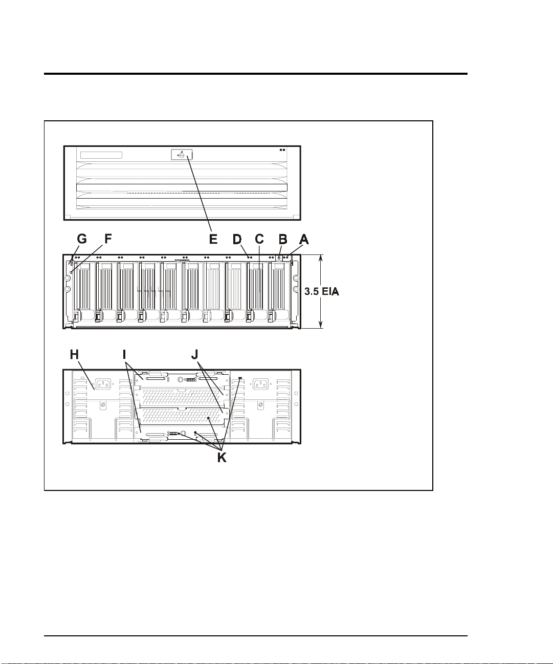
A system LEDs
B power button
C disk module
D disk module LEDs
Edoor lock
FESD plug
G mounting ea r
H power supply
IBCCs
Jfans
K component LEDs
Figure 3
Disk Enclosure Front and Back View
Power Switch
The power switch (B in Figure 3) interrupts power from the power supplies to t he disk
enclosure component s. Power to the power supplies is cont rolled by the power cords and
the AC source.
26 Disk Enclosure Components
Page 27

Disk Enclosure SC10 Modules
The disk enclosure hot-sw appable modules include th e following:
Disks and fillers
•
Fans
•
Power supplies
•
Disks and Fillers
Hot-swappable disk modules make it easy to add or replace disks. Fillers are required in all
unused slots to maintain proper airflow within the enclosure.
Figure 4 illustrates the 3.5-inch disks in a metal carrier. The open carrier design allows ten
half height (1.6 inch) disks to fit the 19-inch width of a standard rack and meet cooling
needs.
WARNING Touching exposed circuits on the disk module can damage the disk
drive inside. T o avoid damage, always handle disks carefully and use
ESD precautions.
Product Description
The following plastic parts of the disk are safe to touch:
Bezel-handle (A in Figure 4)
•
Cam latch (B)
•
Insertion guide (F)
•
Metal standoffs (D) protect exposed circuits against damage when the disk is laid
circuit-side down on a flat surface.
Disk Enclosure Components 27
Page 28
A bezel handle
B cam latch E circuit board
C car rier frame F insertion guide
D standoffs G capacity label
Figure 4
Disk Module
Disks fit snugly in their slots. The cam latch (B in Figure 4) is used to seat and unseat the
connectors on the backplane.
A label (G) on the disk provides the following information:
Disk mechanism height: 1.6 inch (h alf height) or 1 inch (low profile)
•
Rotational speed: 10K RPM and 15K RPM (18 Gbyte only)
•
Capacity: 9.1 Gbyte, 18.2 Gbyte, 36.4 Gbyte, or 73.4 Gbyte
•
A large zero on the capacity label distinguishes a filler from a disk. Fillers are required in all
unused slots to maintain proper airflow within the enclosure.
C
AUTION
Fillers must be installed in unused slots to maintain proper cooling within
the disk enclosure.
28 Disk Enclosure Components
Page 29
BCCs
T wo Backplane Controller Cards, BCCs, control the disks on one or two buses according to
the setting of the Full Bus switch. When the Full Bus switch is set to on, BCC A, in the top
slot, accesses the disks in all ten slots. When the Full Bus switch is off, BCC A accesses
disks in the even-numbered slot s and BCC B accesses disks in the odd-numbered slots.
Product Description
Note
In full bus mode, all ten disks can be accessed through either BCC. Howeve r,
internally each BCC still manages five disks. This means that if the BCC that is
not connected to the SCSI channel fails, access to its five disks will be lost.
Failure of the BCC that is connected to the SCSI channel will render all ten
disks inaccessible.
A alignment guides
B SCSI Ports E DIP switches
CLEDs Flocking screw
D rotary switch G cam lever
Figure 5
BCC
Disk Enclosure Components 29
Page 30

Each BCC provides two LVD SCSI ports (B in Figure 5) for connection to the controller
enclosure.
The EEPROM on each BCC store s 2
data, including the manufacturer serial number, World Wide Name, and product number.
The following are additional features of the BCC:
LEDs (C in Figure 5) show the status of the BCC and the bus.
•
A rotary switch (D) used to set the enclosure (tray) ID which is used by internal
•
controller operations, and also by the management tools to identify each enclosure.
DIP switches set disk enclosure option s. The only option used by the Disk Array FC60
•
is the full-bus/split-bus mode.
Screws (F) prevent the card from being unintentionally disconnected .
•
Cam levers (G) assist in installing a nd removing the BCC from the enclos ure, ensuring
•
a tight connection with the backplane.
BCC functions include dr ive addressing, fault detection, and environmental services.
bytes of configuration information and user-defined
K
30 Disk Enclosure Components
Page 31

Fans
Redundant, hot-swappable fans pr ovide cooling for all enclosure components. Each fan has
two internal high-speed blowers (A in Figure 6), an LED (B), a pull tab (C), and two locking
screws (D).
Product Description
A internal blowers
BLED
Cpull tab
D locking scre w s
Figure 6
Fan
Internal circuitry senses blower motion and triggers a fault when the speed of either blower
falls below a critical level. If a fan failure occurs, the amber f au lt L ED will go on. An alert
should also be generated by EMS Hardware Monitoring when a fan failure occurs.
Disk Enclosure Components 31
Page 32

Power Supplies
Redundant, hot-swapp ab le 450-watt power supplies conver t wide- r an gi n g AC vo ltage from
an external main to stable DC output and deliver it to the backplane. Each power suppl y
has two internal blowers, an AC receptacle (A in Figure 7), a cam handle (B) with locking
screw, and an LED (C). Internal control prevents the rear DC connector from becoming
energized when the power supply is removed from the disk enclosure.
Figure 7
Note
AAC receptacle
B cam handle
CLED
Power Supply
NOTE:
LED position varies.
Although it is possible to operate the disk enclosure on one power supply, it is
not recommended. Using only one supply creates a single point of failure. If the
power supply fails, the entire enclosure is inaccessible. To maintain high
availability, both power supplies should be used at all times, and a failed supply
should be replaced as soon as possible.
32 Disk Enclosure Components
Page 33

Power supplies share the load reciprocally; that is, each supply automatically increases its
output to compensate fo r reduced output from the other. If one power supply fails, the
other delivers the entire load.
Internal circuitry triggers a fault when a power supply fan or other power supply part fails.
If a power supply failure occurs, the amber f ault LED will go on. An alert should also be
generated by EMS Hardware Monitoring when a power supply failure occurs.
Product Description
Disk Enclosure Components 33
Page 34

Array Controller Enclosure Components
The array controller e nclosure, like the disk enclosure, consists of several modules that
can be easily replaced, plus several additional internal assemb lies. See Figure 8. Together,
these removable modules and internal assemblies make up the field replaceable units
(FRUs). Many modules can be remov ed and replaced without disrupting disk array
operation.
The following module s are contained in the controller enclosure:
Controller modules
•
Controller fan module
•
Power supply modules
•
Power supply fan module
•
Battery backup unit
•
34 Array Controller Enclosure Components
Page 35

Controller Fan
Product Description
Power Supply Fan
Module
Power Supply Modules
Controller Chassis
dule A
dule B
(Front Cover Not Shown)
Figure 8
Controller Enclosure Exploded View
Controller Mo
Controller Mo
BBU
During operation, controller enclosure status is indicated by five LEDs on the front left of
the controll er enclo sure. F aults de tected by the contro ller mo dule cause the correspo nding
controller enclos ure fault LED to go on. Additional LEDs o n the individual components
identify the failed component. See "T roubleshooting" on page 359 for detailed information
on LED operation.
Array Controller Enclosure Components 35
Page 36

Figure 9
Controller Enclos ur e Fr ont V iew
36 Array Controller Enclosure Components
Page 37
Product Description
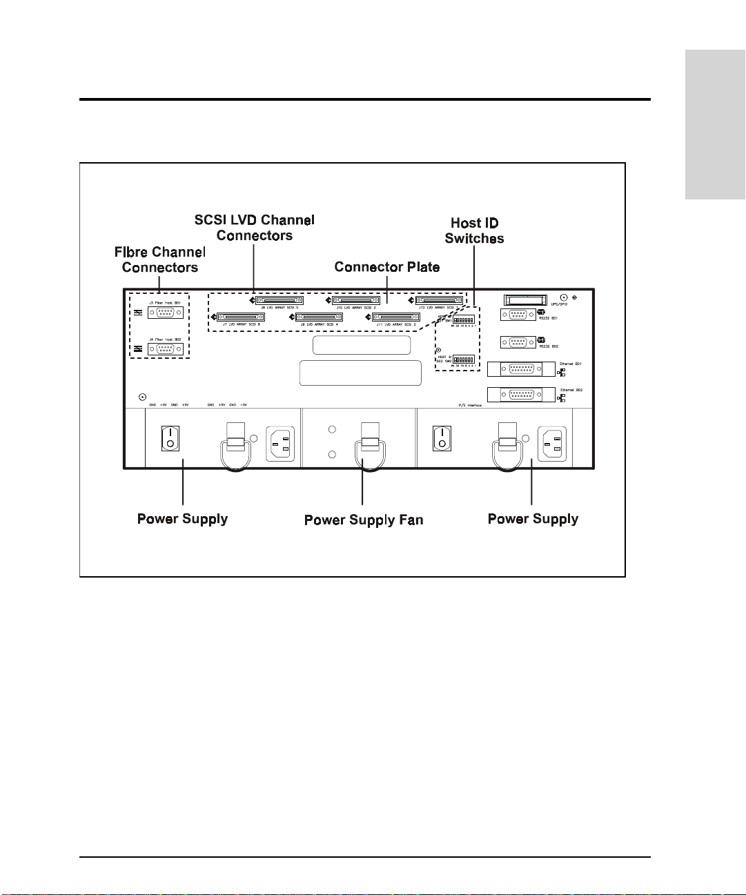
Figure 10
Controller Enclosure Rear View
Front Cover
The controller enclosure has a removable front cover which contains slots for viewing the
main operating LEDs. The cover also contains grills that aid air circulation. The cont roller
modules, controller fan, and battery backup unit are located behind this cover. This cover
must be removed to gain ac cess to these modu les, and also, to observe th e control ler status
and BBU LEDs.
Array Controller Enclosure Components 37
Page 38

Controller Modules
The controller enclosure contains one or two controller modules. See Figure 11. These
modules provide the main data and status processing for the Disk Array FC60. The
controller modules slide into two controller slots (A and B) and plug directly into the
backplane. Two handles lock the modules in place. Each controller slot has a controller
letter that identifies the physical location of the controller in the chassis: controller slot A
or controller slot B (also known as BD1 and BD2, respectively, as referenced on the back of
the controller enclosure).
Figure 11
38 Array Controller Enclosure Components
Controller Modules
Page 39

Each controller module has ten LEDs. See Figure 12. One LED identifies the controller
module’s power status. A second LE D indicates when a fault is detected. The remaining
eight LEDs provi de detaile d fault co ndition status. The mo st signifi cant LED , the heartb eat,
flashes approximately every two seconds beginni ng 15 seconds after power-on.
"Troubleshooting" on page 359 contains additional information on controller LED
operation.
The controller module connects to the host via Fibre Channel, and to the disk enclosures
via LVD SCSI. Each controller must have a unique host f i bre ID number assigned using the
ID switches on the back of the controller modules. See "Installation" on page 1 43 for more
information on setting host IDs.
Product Description
Figure 12
Controller Module LEDs
Array Controller Enclosure Components 39
Page 40

Controller Memory Modules
Each controller module contains SIMM and DIMM memory modules. Two 16-Mbyte SIMMs
(32 Mbytes total) store controller program and other data required for operation. The
standard controller module includes 256-Mbytes of cache DIMM, which is upgradeable to
512 Mbytes. The cache may be configured as either two 128-Mbyte DIMMs, or a single 256Mbyte DIMM. Cache memory serves as temporary data storage during read and write
operations, improving I/ O performance. When cache mem ory contains write data, the Fa st
Write Cache LED, on the front of the controller enclosure is on. See Figure 13.
Controller Fan Modules
The controller fan module is a single removable unit containing dual cooling fans and
temperature monitoring logic. See Figure 13. It includes five LEDs that indicate overall
system status and controller fan status. The fans provide cooling by pulling air in through
ventilation holes, moving it across the controller cards, and exhausting it out the
ventilation holes in the fan assembly. The dual fans provide a redundant cooling system to
both controller modules. I f one fan fails, the other continues to operate and provide
sufficient air cir cul ation to pr even t the cont roll ers fr om o verh eating unti l the fan m odul e is
replaced. The fan module plugs into a slot on the front of the controller enclosure, and has
a handle and captive screw for easy service.
40 Array Controller Enclosure Components
Page 41

Product Description
Figure 13
Controller Fan Module
Array Controller Enclosure Components 41
Page 42

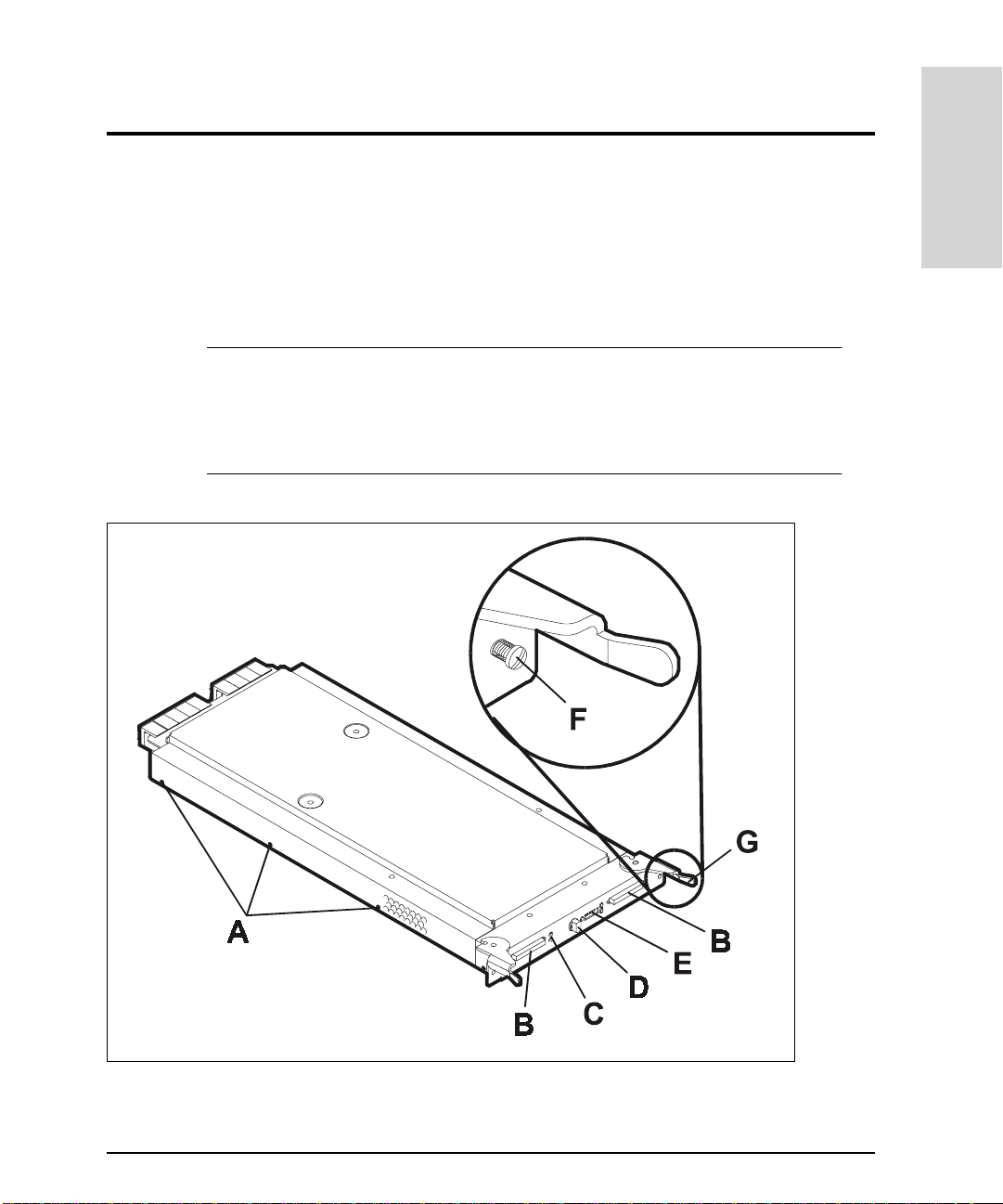
Power Supply Modules
Two separate power supplies provide electrical power to the internal components by
converting incoming AC voltage to DC voltage. Both power supplies are housed in
removable power supply modules that slide into two slots in the back of the controller and
plug directly into the power interface board. See Figure 14.
Figure 14
Power Supply Modules
Each power supply uses a separate power cord. These two power cords are special ferrite
bead cords (part no. 5064-2482) required for FCC compliance. Both power cords can plug
into a common power source or each cord can plug into a sep ar at e circuit (to provide
power source redundancy).
42 Array Controller Enclosure Components
Page 43

Each power supply is equipped wi th a power switch to disconnect powe r to the supply.
Turning off both switches turns off power to the controller. This should not be performed
unless I/O activity to the di sk array has be en sto pped, and the writ e cache h as been f lushed
as indicated by the Fast Write Cache LED being off.
C
AUTION
The controller power switches should not be turned off unless all I/O activity
to the disk array has been suspended from the host. Also, power should not be
turned off if the Fast Write Cache LED is on, indicating that there is data in
the write cache. Wait until t he Fast Write Cache LED goes off before shutting
off power to the disk array.
Each power supply is equipped with a power-on LED indicator. If the LED is on (green) the
supply is providing dc power to the controller. If the LED is off, there is a malfunction or
the power has been interrupted. The system Power Fault LED on the front of the controller
enclosure works in conjunction with the Power Supply LEDs. If both power supplies are
on, the system Power Fault LED will be off . If eit her power supply is off or in a fault state,
the system Power Fault LED go es on. When both power supplies are off or not providing
power to the enclosure, the system power LED on the front of the controller enclosure will
be off.
Product Description
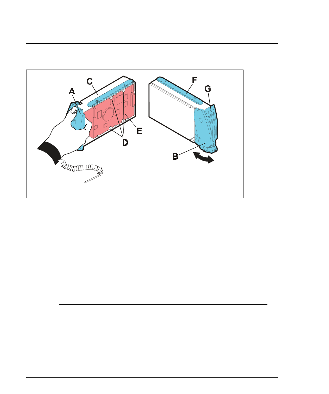
Power Supply Fan Module
Like the controller fan, the power supply fan module (Figure 15) is a single remo vable unit
that contains dual cooling fans. Dual fans provide a redundant cooling system to both
power supply modules. If one fan fails, the other will continue to operate. A single fan will
provide sufficient air circulation to prevent the power supplies from overheating until the
entire power supply fa n module can be replaced. Th e power supply fan module plugs
directly into a slot on the ba ck of the controller enclosure, between the power supplies. It
has a locking lever that allow s it to be unlatched and removed.
The power supply fan can b e hot swapped, provided the exchang e is pe rformed within 15
minutes. This time limit applies only to the total time during whic h t he fan is out of the
enclosure, beginning when you remove the failed unit and ending when you re-seat the new
one. This does not include the time it takes you to perform this entire procedure (including
checking LEDs).
Array Controller Enclosure Components 43
Page 44
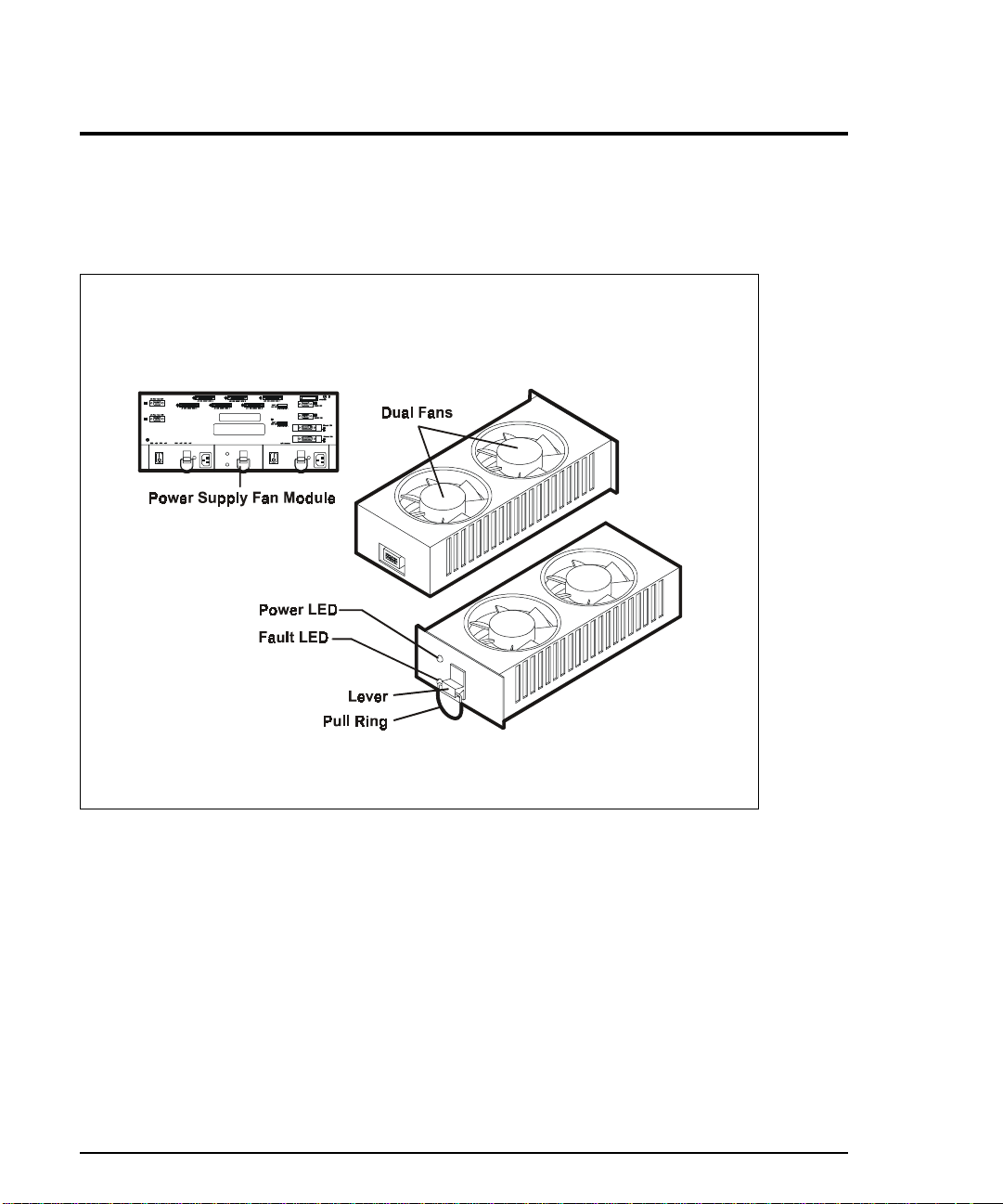
Figure 15
Power Supply Fan Module
44 Array Controller Enclosure Components
Page 45
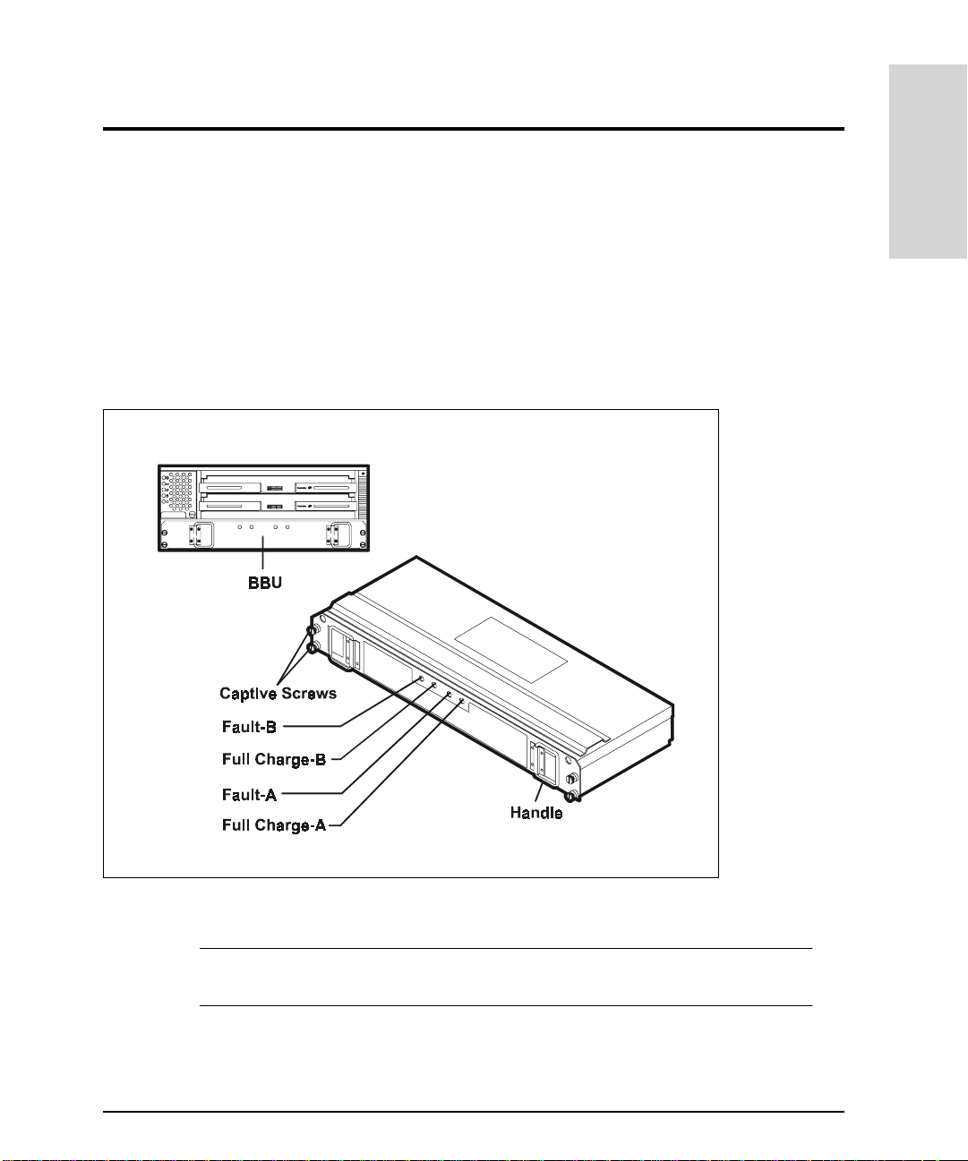
Battery Backup Unit
The controller enclosure contains one removable battery backup unit (BBU) that houses
two rechargeable internal batteries (A and B) and a battery charger board. The BBU plugs
into the front of the controller enclosure where it provides backup power to the
controller’s cache memory during a power outage. The BBU will supply pow er to the
controllers for up to five days (120 hrs). All data stored in memory will be preserved as long
as the BBU supplies power. When power to the disk array is restored, the cache data will
be written to disk.
Product Description
Figure 16
C
AUTION
Battery Backup Unit
During a power outage, do not remove the controller or the BBU. Removing
either of these modules can compromise data integrity.
Array Controller Enclosure Components 45
Page 46

The BBU contains four LEDs that identify the condition of the battery. Internally, the BBU
consists of two batteries or banks, ide nt ified as bank “A” and bank “B.” During normal
operation both of the Full Charge LEDs (Full Charge-A and Full Charge-B) are on and the
two amber Fault LEDs are off. If one or both of the Fault LEDs are on, refer to
"Troubleshooting" on page 359 for information on solving the problem. The Full Charge
LEDs flash while the BBU is charging. It can take up to seven hours to fully charge a new
BBU.
Battery Operation and Replacement
Replace the BBU every two years or whenever it fails to hold a charge, as indicated by the
BBU Fault LEDs. The service label on the BBU provides a line for recording the date on
which the BBU was serviced. Check this label to de termine when to replace the BBU.
When a BBU is replaced, it may require up to seven hours to fully charge. The Full Charge
LEDs flash while the BBU is charging, and remain on when the BBU is fully charged.
If you replace the BBU and still experience battery-related problems (such as a loss of
battery power to the controllers or batteries not charging properly), the controller
enclosure may have some other internal component failure. In this case contact your HP
service en gineer.
Battery Operation for No Data Loss
The BBU protects the write cac he (dat a which has no t bee n writt en to d isk) fo r at l east 12 0
hours (five days) in case of a power failure. When power to the disk array is restored, data
in the cache is written to the disks and no data loss occu rs. How ever, if the system is to be
powered off for more than 120 hours, it is imperative that a proper shutdown procedure be
executed or data may be lost. The following are rec ommendations:
Battery status must always be checked and replaced when a failure is indicated.
•
Never remove the BB U wit hout first performing a proper shutdown proced ure.
•
For a planned shutdown, make sure t hat all data has been written to disks before
•
removing power. This is indicated by the Fast Write Cache LED which will be off when
there is no longer any data in write cache. See Figure 13.
If the BBU is removed, do not shut off power to the array unless the Fast Write Cache
•
LED is off. Data in write cache will be posted to disk 10 seconds after the BBU is
removed.
46 Array Controller Enclosure Components
Page 47

Disk Array High Availability Features
High availability systems are designed to provide uninterrupted operation should a
hardware failure occur. Disk arrays contribute to high availability by ensuring that user
data remains accessible even when a disk or other component within the Disk Array FC60
fails. Selecting the proper Fibre Channel topology and system configuration can p rot ect
against the fail ure of any hard ware comp onent in the I/O path to the di sk array by provi ding
an alternate p ath to all user data.
The Disk Array FC60 provides high ava ilability in the following ways:
• Supported RAID levels 1, 0/1, 3, and 5 all use data redundancy to protect data when a disk
failure oc curs. RAID 0 is support ed but it do es not offe r data re dundanc y and shou ld not
be used in high-availability environm ents.
• Global hot spare disks serve as automatic replacements for failed disks.
Product Description
• Alternate hardware paths to user data protects against I/O path failures.
• Redundant, hot-swappable hardware components can be replaced without interrupting
disk array operati o n.
RAID Technology
RAID technology contributes to high availability through the use of data redundancy,
which ensures that da ta on the di sk array rem ains avail able e ven if a disk or channe l failur e
occurs. RAID technolog y uses two techniques to achieve data redundancy: mirroring and
parity. A third characteristic of RAID technology, data striping, enhances I/O performance.
Disk Mirroring
Disk mirroring achieves data redundancy by maintaining a duplicate copy of all data. Disks
are organized into pairs: one disk serves as the data disk, the other as the mirror which
contains an exact image of its data. If either disk in the pair fails or becomes inaccessible,
the remaining disk provides uninterrupted access to the data.
Disk Array High Availability Features 47
Page 48

The disk array uses hardware mirroring, in which the disk array automatically
synchronizes the two disk images, without user or operating system involvement. T h is is
unlike the software mirroring, in which the host oper at ing system software (for example,
LVM) synchronizes the disk images.
Disk mirroring is used by RAID 1 and RAID 0/1 LUNs. A RAID 1 LUN consists of exa ctly
two disks: a primary disk and a mirror disk. A RAID 0/1 LUN consists of an even number of
disks, half of which are primar y disks and the other half are mirror disks. I f a disk f ails or
becomes inaccessible, the remaining disk of the mirrored pair provides uninterrupted data
access. After a failed disk is replaced, the disk array automatically rebuilds a copy of the
data from its companion disk. To protect mirrored data from a channel or internal bus
failure, each disk in the LUN should be in a different enclosure.
Data Parity
Data parity is a second techniqu e used to achieve data redundanc y. If a disk fails or
becomes inaccessible, the parity data can be combined with data on the remaining disks in
the LUN to reconstruct the data on the failed disk. Data parity is used for RAID 3 and RAID
5 LUNs.
To ensure high availability, each disk in the LUN should be in a separate enclosure. Parity
cannot be used to recon s tr uct data if more than one disk in the LUN is unavailable.
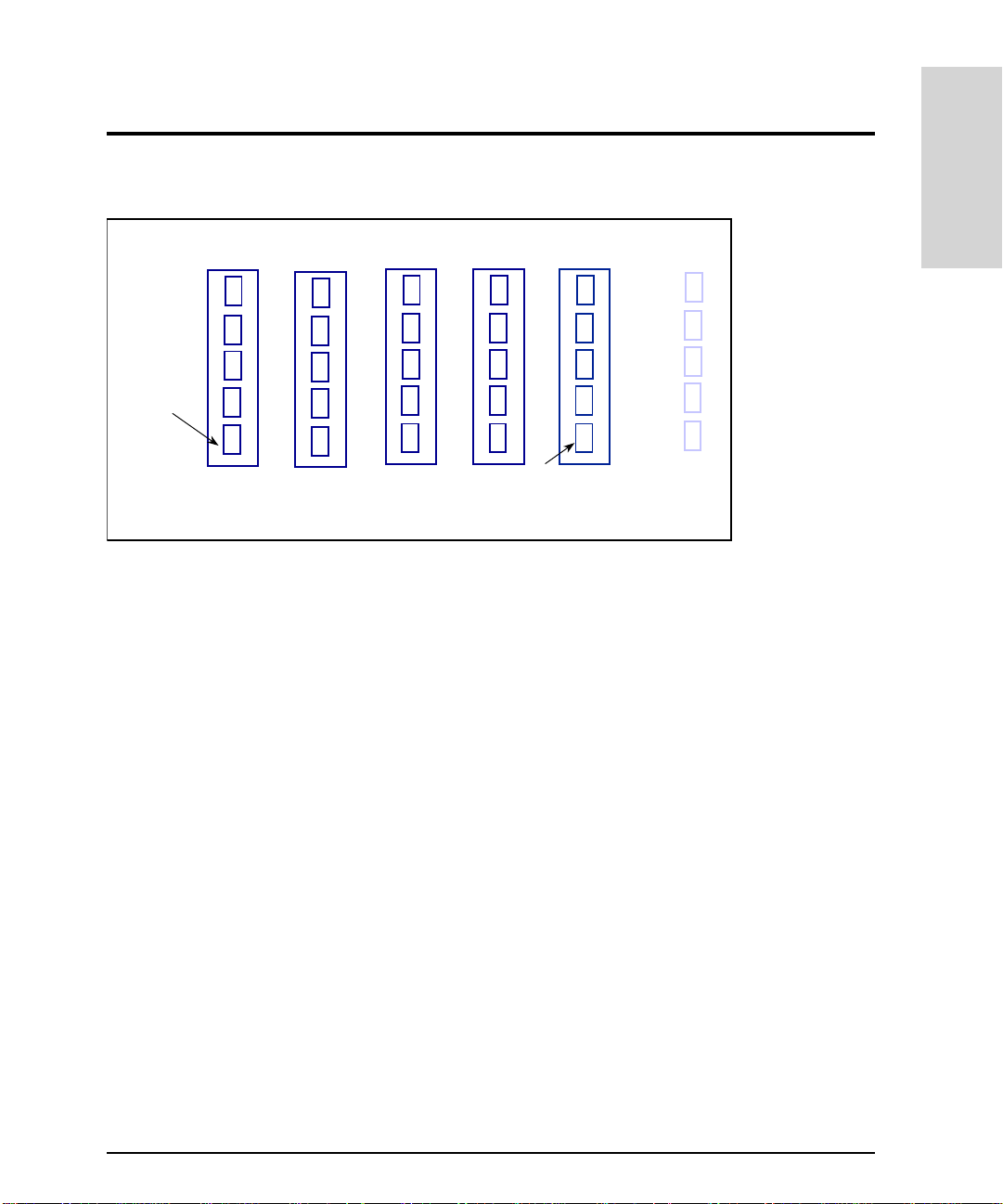
Parity is calculated on each write I/O by doing a serial binary exclusive OR (XOR) of the
data segments in the stripe written to the data disks in the LUN. The exclusive OR
algorithm requires an even number of binary 1s to create a result of 0.
Figure 17 illustrates the pr ocess for calculating parity on a five-disk LUN. The data written
on the first disk is “XOR’d” with the data written on the second disk. The result is “XOR’d”
with the data on the third disk, which is “XOR’d” with the data on the fourth disk. The
result, which is the parity, is written to the fifth disk. If any bit changes state, the parity also
changes to maintain a resul t of 0.
48 Disk Array High Availability F eatures
Page 49
Product Description
Data Data Data Data Parity
0
=
0
0
0
0
If this bit is
now written
as 1...
Figure 17
0
1
1
0
0
Calculating Data Parity
1
++ +
0
1
0
1
1
0
1
1
0
1
+
1
0
0
1
This bit will also
be changed to a 1
so the total still
equals 0.
1
0
1
1
0
Data Striping
Data striping, which is used on RAID 0, 0/1, 3 a nd 5 LUNs, is the performance-enhancing
technique of reading and writing data to uniformly s i zed segments on all disks in a LUN
simultaneously. Collectively, the segments comprise a stripe of data on the LUN. Data
striping enhances performance by allowing multiple sets of read/write heads to execute the
same I/O transaction simultaneously.
The amount of information simultaneously read from or wr itten to each disk is the stripe
segment size. The stripe segment size is configurable to provide optimum performance
under varying sizes of I/O transactions. Stripe segment size is specified in 512-byte blocks
of data.
Stripe segment si ze can affect disk ar ra y p er fo r ma nc e. The smaller the stri pe segment size,
the more efficient the distribution of data read or written across the stripes in the LUN.
However, if the stripe segment is too small for a single I/O operation, the operation requires
access to two stripes. Called a stripe boundary crossing, this action may negatively impact
performance.
The optimum stripe segment size is the smallest size that will rarely force I/Os to a second
stripe. For example, assume your application uses a typical I/O size of 6 4
Disk Array High Availability Features 49
B. If you are
K
Page 50

using a 5-disk RAID 5 LUN, a stri pe segm ent size of 32 bl ocks (1 6 KB) would ensure that an
entire I/O would fit on a single str ipe (16
The total stripe size is the number of disks in a LUN multiplied by the stripe segment size.
For example, if the stripe segment size is 32 blocks and the LUN comprises five disks, the
stripe size is 32 X 5, or 160 blocks (81,920 bytes).
B on each of the four data disks).
K
RAID Levels
RAID technology uses a number of different techniques for storing data and maintaining
data redundancy. These industry-standard RAID levels define the method used for
distributing data on the disks in a LUN. LUNs that use different RAID levels can be created
on the same disk array.
The Disk Array FC60 supp orts the following RAID levels:
RAID 0
•
RAID 1
•
RAID 0/1
•
RAID 3 (Windows NT and Windows 2000 only)
•
RAID 5
•
RAID 0
C
AUTION
RAID 0 uses disk striping to achieve high performance. Data is striped across all disk in the
LUN. The ability to access all disks in the LUN simultaneously provides a high I/O rate. A
RAID 0 group configura tion for a logical disk unit offe rs fast access, but without the hi gh
availability offered by the ot her RAID levels.
Unlike other RAID levels, RAID 0 does not provi de data redundancy, er ror recovery, or
other high availability features. Consequently it should not be used in environments where
high-availability is critical. All data on a RAID 0 LUN is lost if a single disk within the LUN
50 Disk Array High Availability F eatures
RAID 0 does not provide data redundancy. It should only be used in
situations where high performance is more important than data protection.
The failure of any disk within a RAID 0 LUN will cause the loss of all data on
the LUN.. RAID 0 should only be used for non-critical data that could be lost
in the event of a hardware failure.
Page 51
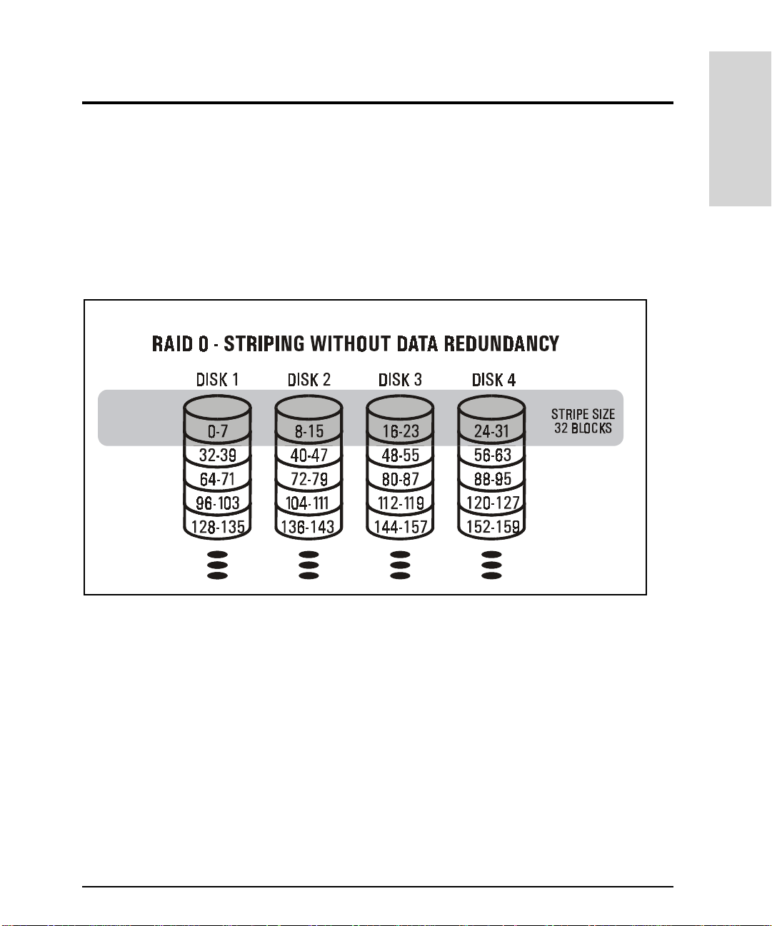
fails. RAID-0 provides enhanced pe rformance through simultan eous I/Os to multiple disk
modules. Software mirroring the RA ID-0 group provides high availability.
Figure 18 illustrates the distribution of user and parity data in a four-disk RAID 0 LUN. The
the stripe segment size is 8 blocks, and the stripe size is 32 blocks (8 blocks times 4 disks).
The disk block addresses in the stripe proceed sequentially from the first disk to the
second, third, and fourth, then back to the first, and so on.
Product Description
Figure 18
RAID 0
LUN
RAID 1
RAID 1 uses mirroring to achieve data redundancy. RAID 1 provides high availability and
good performance, but at the cost of storage efficiency. Because all data is mirrored, a
RAID 1 LUN has a storage efficiency of 50%.
A RAID 1 LUN co nsists of exactl y two disks configured as a mirrored pair. One disk is the
data disk and the other is the disk mirror. The disks in a RAID 1 LUN are mirrored by the
disk array hardware, which au tomatically writes data to both t he data disk and the disk
mirror. Once bound into a RAID 1 mirrored pair, the two disks cannot be accessed as
Disk Array High Availability Features 51
Page 52

individual disks. For highest data availability, each disk in the mirrored pair must be
located in a different enclosure.
When a data disk or disk mirror in a RAID 1 LUN fails, the disk array automatically uses the
remaining disk for data access. Until the failed disk is replaced (or a rebuild on a global hot
spare is completed ), the LUN operates in degraded mo de. While in degraded mode the LUN
is susceptible to the failure of the second disk. If both disks fail or become ina cc essible
simultaneously, the data on the LUN becomes inaccessible.
Figure 19 shows the dist ribution of data on a RAID 1 LUN. Note that all data on the data
disk is replicated on the disk mirror.
Figure 19
RAID 1
LUN
RAID 0/1
RAID 0/1 uses mirroring to achieve data redundancy and disk strip ing to enhance
performance. It combines the speed advantage of block striping with the redundancy
advantage of mirroring. Because all data is mirrored, a RAID 0/1 LUN has a storage
efficiency of 50%.
A RAID 0/1 LUN contains an even number of from four to 30 disks. One half of the disks are
primary disks and th e other ha lf are disk mirror s. The disks in a RAID 0/ 1 LUN are mi rrored
by the disk array hardw ar e, w hich automatically writes da ta to both disks in the mirrored
52 Disk Array High Availability F eatures
Page 53

pair. For highest data availability, each disk in the mirrored pair must be located in a
different enclosure.
When a disk fails, th e d i sk ar ray au to m ati ca l ly us es t he re maining disk of the mi rr o re d pai r
for data access. A RAID 0/1 LUN can survive the failure of multiple disks, as long as one
disk in each mirrored pa ir re mains acc essib le. Unti l the fai led disk is rep laced (o r a reb uild
on a global hot spare is completed), the LUN operates in degraded mode. While in degraded
mode, the LUN is susceptible to the failure of th e second disk of the pair. If both disks fail
or become inac cessible simultaneously, the data on the LUN becomes inaccessible.
Figure 20 illustrates the distribution of data in a four-module RAID 0/1 LUN. The disk block
addresses in the stripe proceed sequentially from the first pair of mirrored disks (disks 1
and 2) to the second pair of mirrored disks (disks 3 and 4), then again from the first
mirrored disks, and so on.
Product Description
Figure 20
RAID 0/1
LUN
RAID 3
RAID 3 uses parity to achieve data redundancy and disk striping to enhance performance.
Data is distributed across all but one of the disks in the RAID 3 LUN. The remaining disk is
used to store parity information for each data stripe. A RAID 3 LUN consists of three or
Disk Array High Availability Features 53
Page 54

more disks. For highest availability, the disks in a RAID 3 LUN must be in different
enclosures.
If a disk fails or becomes inaccessible, the disk array can dynamically reconstruct all user
data from the data and parity information on the remaining disks. When a failed disk is
replaced, the disk array automatically rebuilds the contents of the failed disk on the new
disk. The rebuilt LUN contains an exact replica of the information it would have contained
had the disk not failed.
Until a failed disk is replaced (or a rebuild on a global hot spare is completed), the LUN
operates in degraded m ode. The LUN must now use the data an d parity on the remaining
disks to recreate the content of the f ailed disk, which reduces performa nce. In addition,
while in degraded mode, the LUN is susceptible to the failure of the second disk. If a
second disk in the LUN fails while in degraded mode, parity can no longer be used and all
data on the LUN becomes inaccessible.
Figure 21 illustrates th e distribution of user and parity data in a five-disk RAID 3 LUN. The
the stripe segment size is 8 blocks, and the stripe size is 40 blocks (8 blocks times 5 disks).
The disk block addresses in the stripe proceed sequential ly from the first disk to th e
second, third, and fourth, then back to the first, and so on.
Figure 21
54 Disk Array High Availability F eatures
RAID 3
LUN
Page 55

RAID 3 works well for single-task applications using large block I/Os. It is not a good
choice for transaction processing systems because the dedicated parity drive is a
performance bottleneck. Whenever data is written to a data disk, a write must also be
performed to the parity drive. On write operations, the parity disk can be written to four
times as often as any other disk modul e in the group.
RAID 5
RAID 5 uses parity to achieve data redundancy and disk striping to enhance performance.
Data and parity inf or m atio n i s d ist ri bu ted ac ro ss a l l the d i sk s in th e R AI D 5 L U N. A R AID 5
LUN consists of three or more disks. For highest availability, the disks in a RAID 5 LUN
must be in different enclos ures.
If a disk fails or becomes inaccessible, the disk array can dynamically reconstruct all user
data from the data and parity information on the remai ning disks. When a failed disk is
replaced, the disk array automatically rebuilds the contents of the failed disk on the new
disk. The rebuilt LUN contains an exact replica of the information it would have contained
had the disk not failed.
Product Description
Until a failed disk is replaced (or a rebuild on a global hot spare is completed), the LUN
operates in degraded mode. The LUN must now use the data and parity on the remaining
disks to recreate the content of the f ailed disk, which reduces performa nce. In addition,
while in degraded mode, the LUN is susceptible to the failure of the second disk. If a
second disk in the LUN fails while in degraded mode, parity can no longer be used and all
data on the LUN becomes inaccessible.
Figure 22 illustrates th e distribution of user and parity data in a five-disk RAID 5 LUN. The
the stripe segment size is 8 blocks, and the stripe size is 40 blocks (8 blocks times 5 disks).
The disk block addresses in the stripe proceed sequentially from the first disk to the
second, third, fourth, and fifth, then back to the first, and so on.
Disk Array High Availability Features 55
Page 56

Figure 22
RAID 5
LUN
With its individual access characteristics, RAID 5 provides high read throughput for small
block-size requests (2
B to 8KB) by allowing simultaneous read operations from each
K
disk in the LUN. During a write I/O, the disk array must perform four individual operations,
which affects the write performance of a RAID 5 LUN. For each write, the disk array must
perform the following steps:
1. Read the existing user data from the disks.
2. Read the corre sponding parity information.
3. Write the new user data.
4. Calculate and write the new parity information.
Write caching can significantly improve the write performance of a RAID 5 LUN. RAID 5 is
good for parallel processing (multi-tasking) applications and environments. T he
performance of a RAID 5 LUN is best when the maximum number of disks (six ) is used.
56 Disk Array High Availability F eatures
Page 57

RAID Level Comparisons
To help you decide whic h RAID level to select for a LUN, the following tables compare the
characteri stics for th e supported RAI D levels. Wher e appropriate, the relati ve strengths
and weakness of each RAID level are noted.
Product Description
Note
RAID 3 is supported on Windows NT and Windows 200 0 only.
Table 1
RAID Level D isk Striping Mirroring Parity
RAID 0 Yes No No No. RAID 0 offers no data
RAID 1 No Yes No No
RAID 0/1 Yes Yes No Yes, providing both disks in
RAID 3 Yes No Yes No
RAID 5 Yes No Yes No
RAID Level Comparison: Data Redundancy Characteristics
Handle multiple disk
failures?
redundancy or protection
against disk failure. RAID 0
should only be used for noncritical data. The failure of a
single disk in a RAID 0 LUN
will result in the loss of all
data on the LUN.
a mirrored pair do not fail.
Disk Array High Availability Features 57
Page 58

Table 2
RAID Level Storage Efficiency
RAID 0 100%. All disk space is use for data storage.
RAID 1 and 0/1 50%. All data is duplicated, requiring twice the disk storage for a
RAID 3 and 5 One disk’s worth of capacity from each LUN is required to store
Table 3
RAID Level Comparison: Storage Efficiency Characteristics
given amount of data capacity.
parity data. As the number of disks in the LUN increases, so does
the storage efficienc y.
3-disk LUN: 66%
4-disk LUN: 75%
5-disk LUN: 80%
6-disk LUN: 83%
RAID Level Comparison: Relative Performance Compared to an Individual Disk*
LUN Configuration
RAID 0 The read and write performance of a RAID 0 LUN increases as
RAID 1 mirrored pair Up to 2.0 > than single disk Equal to single disk
RAID 0/1 group with 10 disks Up to 10.0 > than single disk Up to 5.0 > than single disk
RAID 0/1 group with 6 disks Up to 6.0 > than single disk Up to 3.0 > than single disk
RAID 3 group with 5 disks Up to 4.0 > than single disk Up to 1.25 > than single disk
RAID-5 group with 5 disks Up to 4.0 > than single disk Up to 1.25 > than single disk
* Compares the rel ative read and write performance for array configurations with the
performance of a single stand-alone disk whose performance is 1.0. The read and write
performanc e shown is the theoretical max imum performance relative to individual di s k
performance. The performance numbers are not based on read/write caching. With caching,
the performance numbers for RAID 5 writes improve significan tly.
Relative Read Performance
for Large Sequential Access
the multiple of the number of disks in the LUN. For example, a
4-disk RAID 0 LUN will achieve close to four times the
performance of a single disk.
Relative Write Performance
for Large Sequential Access
58 Disk Array High Availability F eatures
Page 59
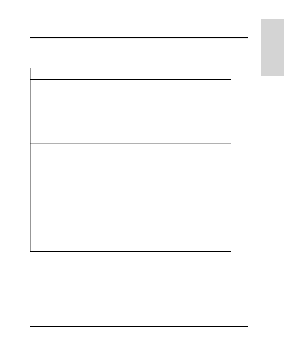
Table 4
RAID Level General P erformance Characteristics
RAID 0 – Simultaneous access to multiple disks increases I/O performance. In
RAID 1 – A RAID 1 mirrored pair requires one I/O operation for a read and two I/O
RAID 0/1 – Simultaneous access to multiple mirrored pairs increases I/O performance.
RAID 3 – Provides high read throughput for large sequential I/Os.
RAID Level Comparison: General Performance Characteristics
general, the greater the number of mirrored pairs, the greater the increase
in performance.
operations for a write, one to each disk in the pair.
– The disks in a RAID 1 mirrored pair are locked in synchronization, but the
disk array can read data from the module whose read/write heads are the
closest.
– RAID 1 read performance can be twice that of an individual disk. Write
performance can be the same as that of an individual disk.
In general, the greater the number of mirrored pairs, the greater the
increase in performance.
– Write performance is limited by the need to perform four I/O operations per
write request.
– Because some I/O operations occur simultaneously, performance depends
on the number of disks in the LUN. Additional disks may improve
performance.
– The I/O performance of RAID 5 benefits significantly from write caching.
Product Description
RAID 5 – Provides high read throughput for small block-size requests (2 KB to 8 KB).
– Write performance is limited by the need to perform four I/O operations per
write request.
– Because some I/O operations occur simultaneously, performance depends
on the number of disks in the LUN. Additional disks may improve
performance.
– The I/O performance of RAID 5 benefits significantly from write caching.
Disk Array High Availability Features 59
Page 60

Table 5
RAID level Application and I/O Pattern Performance
RAID 0 R AID 0 is a good choice in the following situations:
RAID 1 RAID 1 is a good choice in the following situations:
RAID 0/1 RAID 0/1 is a good choice in the following situations:
RAID Level Comparison: Application and I/O Pattern Performance Characteristics
– Data protection is not critical. RAID 0 provides no data redundancy for
protection against disk failure .
– Useful for scratch files or other temporary data whos e loss will not seri ously
impact system operation.
– High performance is important.
– Speed of write access is important.
– Write activity is heavy.
– Applications need logging or recordkeeping.
– Daily updates need to be stored to a database residing on a RAID 5 group.
The database updates on the RAID 1 group can be copied to the RAID 5
group during off-peak hours.
– Speed of write access is important.
– Write activity is heavy.
– Applications need logging or recordkeeping.
– Daily updates need to be stored to a database residing on a RAID 5 group.
The database updates on the RAID 1 group can be copied to the RAID 5
group during off-peak hours.
RAID 3 RAID 3 is a good choice in the following situations:
– Applications using I/O large sequen tial transfer s of data, such as multimedia
applications.
– Applications on which write operations are 33% or less of all I/O operations.
RAID 5 R AID 5 is a good choice in the following situations:
– Multi-tasking applications using I/O transfers of different sizes.
– Database repositories or database servers on which write operations are
33% or less of all I/O operations.
– Multi-tasking applications requirin g a large histo ry database with a high read
rate.
– Transaction processing is required.
60 Disk Array High Availability F eatures
Page 61

Global Hot Spare Disks
A global hot spare disk is reserved for use as a replacemen t disk if a data d i sk fails. Their
role is to provide hardware redundancy for the disks in the array. To achieve the highest
level of availability, it is recommended that one global hot spare disk be created for each
channel. A global hot spare can be used to replace any failed data disk within the array
regardless of w hat channel it is on.
When a disk fails, the disk array automatically begins rebuilding the failed disk’s data on an
available global hot spare. When all the data has been rebuilt on the global hot spare, the
LUN functions normall y, using the globa l hot spa re as a rep lacem ent for the fail ed disk . If a
global hot spare is not available, data is still accessible using the redundant data
maintained by the LUN.
When the failed disk is replaced, all da ta is copied from the former global hot spare onto
the replacement disk. When the copy is complete, the former global hot spare is returned to
the global hot spare disk group and is again availa ble as protection against another disk
failure.
Product Description
If a failed disk is replaced while dat a is being rebuilt on the global hot spare, the rebuild
process continues until complete. When all data is rebuilt on the global hot spare, it is then
copied to the replacement disk.
Global hot spares are an essential component for maintaining data availability. A global hot
spare reduces the risk of a second disk fai l ure an d restores the disk array’s performa nc e,
which may be degraded while the LUN is forced to recreate data from parity. The use of
multiple global hot spares may be de sirable in environments where data availability is
crucial. Multiple global hot spares ensure that data remains accessible even if multiple
disks fail.
Rebuilding Data
The rebuild process occurs any time a disk failure occurs. It uses the existing data and
parity or mirror disk to rebuild the data that was on the failed disk. Because it is competing
with host I/Os for disk array resources, a rebuild may affect disk array performance. The
effect on performance is controlled by the rebuild priority set tings. These settings
determines how the disk array divides resources between the rebuild and host I/Os.
Disk Array High Availability Features 61
Page 62

Settings that give a higher priority to the rebuild process will cause the rebuild to complete
sooner, but at the expense of I/O performance. Low er rebuild priority settings favors host
I/Os, which will maintain I/O performance but delay the completion of the rebuild.
The rebuild priority settings selected reflect the importance of performance versus data
availability. The LUN being rebuilt is vulnerable to another disk failure while the rebuild is
in progress. The longer the rebuild takes, the greater the chance of another disk failure.
The following sequence occurs following a disk failure and replacement. Figure 23
illustrates the process. A 5-disk RAID 5 LUN is used for this example.
1. Disk 3 in the RAID 5 LUN fails.
2. The disk array locates an available global hot spare and begins recreating on it the
information that was on the failed disk. The data and parity on the remaining four disks
in the LUN are used to recreate the information.
3. When the rebuild finishes, the global hot spare is part of the LUN, which fulfills the roll
of disk 3.
4. When disk 3 is replaced, the disk array begins copying all the information from the
former global hot spare to the replacement disk.
5. When copying completes, the LUN is restored to its original configuration. The former
global hot spare is ret urned to the g lobal ho t spare disk gr oup and i s availab le to prote ct
against another data disk failure.
Note
Can a lower capacity disk serve as a hot spare for a larger disk?
It is possible for a lower capacity disk to be used as a global hot spare when a
larger disk fails. When a disk failure occurs, the disk array controller looks for
a global hot spare that is lar ge enough to store the data on the faile d disk, not
for a disk that matches the capacity of the failed disk. For example, if an 18
Gbyte disk fails bu t there is only 6 Gbytes of data stored on th e d isk, a 9 Gbyte
global hot spare could be use d.
Although this feature is available, it is recommended that you always select the
largest disks in the ar ray to serve as gl obal hot sp ares. This will en sure that a ny
disk in the array is protected, regardless of how much data is stored on it.
62 Disk Array High Availability F eatures
Page 63

Product Description
Data and parity from the
remaining disks are used to
rebuild the contents of disk 3
on the hot spare disk.
Figure 23
The information on the hot spare is
copied to the replaced disk, and the
hot spare is again available to protect
against another disk failure.
Rebuild Process on a RAID 5 LUN (or Volume Group)
Disk Array High Availability Features 63
Page 64

Primary and Alternate I/O Paths
There are two I/O paths to e ach LUN on the disk array - one thro ugh controller A and one
through controller B. Logical Volume Manager (LVM) is used to establish the primary path
and the alternat e pat h to a LU N. The p rimar y pa th beco mes t he p ath f or all ho st I/O s to th at
LUN.
If a failure occurs in the primary path, LVM automatically switches to the alternate path to
access the LUN. The first time an I/O is performed to the LUN using the alternate path, the
disk array switches owner s h ip of the LUN to the controller on the al ternate path. Once the
problem with the primary path is corrected, ownership of the LUN should be switched
back to the original I/O path to maintain proper load balancing.
The primary path establi s hed using LVM defines the owning controller for the LUN. This
may override the controller ownership defined when the LUN was bound. For exam ple, if
controller A was identified as the owning cont roller when the LUN was bound, and LVM
subsequently established the primary path to the LUN through controller B, controller B
becomes the owning controller.
64 Disk Array High Availability F eatures
Page 65

Capacity Management Features
The disk array uses a numb er of features to manage its disk ca pa ci ty effi c i en tly. The use of
LUNs allow you to divide the total disk capacity into smalle r, more flexible partit ions.
Caching improves disk array performance by using controller RAM to temporarily store
data during I/Os.
Note Differences in HP-UX and Windows NT/2000 Capacity Management
Capacity management on Windows NT and Windows 2000 offers some unique
features. Refer to the
information on Windows-specific features . Some of the terms used in the
Storage Manager 60
listed in the
HP Storage Manager 60 Introduction Guide
HP Storage Manager 60 Introduction Guide
software differ fro m those used here . These terms are also
.
for
HP
Product Description
LUNs
The capacity of the disk ar ray can be divi ded int o entiti es calle d LUNs. In div idual disks are
grouped together to form a LUN. Functionally, each LUN appears to the host operating
system as an individual disk drive.
Although the LUN appears to the host as an individual disk, the use of multiple disks offers
advantages of increased data availability and performance. Data availability is enhanced by
using redundant data stored on a separate disk from the original data. The use of multiple
disks increases performance by allowing simultaneous access to several disks when
reading and writing data.
Disk Groups
A disk group is a collection of individual disks that share a co mmon role in disk array
operation. All disks on the disk array become a member of one of the following disk
groups:
LUN group – Each LUN on the disk array has its own disk group. When a disk is included
•
as part of a newly created LUN, the disk becomes a member of the associated disk
group. There can be only one LUN in each LUN disk group.
Capacity Management Features 65
Page 66

Hot spare group – All disks assigned the role of global hot spare become members of
•
this group. Up to six disks (one for each channel) can be assigned as global hot spares.
Unassigned group – Any disk that is neither part of a LUN nor a global hot spare is
•
considered unassigned and becomes a member of this group. Unassigned dis k s can be
used to create a LUN or can be used as global hot spares. Unassigned disks do not
contribute to the capacity of the disk array.
Disk Array Caching
Disk caching is the technique of storing data tempora rily in RAM while performing I/Os to
the disk array. Using RAM as a temporary storage medium can significantly improve the
response time for many types of I/O ope rations. From the host’s perspective the data
transfer is complete, even if the disk media was not involve d in the transaction. Both write
caching and read caching are always enabled.
Caching enhances disk array I/O performance in tw o ways:
Read I/O If a read I/O r equests data th at is already i n read cache, the disk arr ay
services the request fr om cache RAM, thus avoidin g the much slower
process of accessing a disk for th e data. A pre-fetch capability
enables the disk array to anticipate ne eded data (for example, on a
file transfer) and read it from disk into the read cache, which helps
significantly with sequential read I/Os.
Write I/O During a write I/O, the disk arr ay writes the requested data into write
cache. Rather than writing the modified data back to the disk
immediately, the disk array keeps it in cache and informs the host
that the write is complete. If another I/O affects the same data, the
disk array can update it directly in cache, avoiding another disk
write. Data is flushed to disk at regular intervals (10 seconds) ro
when the cache flush threshold is reached.
Write cache is mirrored between the two disk array controllers. Each controller maintains
an exact image of the write cache on the other controller. If a controller fails, its write
cache content is flushed to the disk by the remaining controller. Because write cache is
mirrored, the operational controller automatically di sables write ca ching until the failed
controller is replaced. After it is replaced, the operational controller automatically reenables write caching. Mirroring effectively reduces the size of availabl e cache by half. A
66 Capacity Management Features
Page 67

controller with 256 Mbytes of cache will use half of the memory to mirror the other
controller, leavin g only 128 Mbytes for its own cache.
The write cache contents cannot be flushed when bo th controllers are removed from the
disk array simultaneously. In this case the write cache image is lost and data integrity on
the disk array is compromised. To avoid this problem,
the disk array simultaneously.
In the event of an unexpected disk array shutdown or loss of power, the BBU provide s
power to cache memory to maintain t he cache for 120 hours (5 days).
remove both controllers from
never
Dynamic Capacity Expansion
If slots are available in the disk enclosur es, you can increase the capac ity of the disk array
without disrupting operation. By simply adding new disks to the array and then crea ting a
new LUN the capacity can be expanded. See "Adding Capacity to the Disk Array" on
page 254 for more information on adding disks and othe r ways of increasing disk array
capacity.
Product Description
Capacity Management Features 67
Page 68

68 Capacity Management Features
Page 69

2 TOPOLOGY AND ARRAY PLANNING
Overview . . . . . . . . . . . . . . . . . . . . . . . . . . . . . . . . . . . . . . . . . . . . . . . . . . . . . . . . . . . . . 70
Array Design Considerations . . . . . . . . . . . . . . . . . . . . . . . . . . . . . . . . . . . . . . . . . . . . 71
Recommended Disk Array Configurations . . . . . . . . . . . . . . . . . . . . . . . . . . . . . . . . . 77
Topologies for HP-UX. . . . . . . . . . . . . . . . . . . . . . . . . . . . . . . . . . . . . . . . . . . . . . . . . . 102
Topologies for Windows NT and Windows 2000. . . . . . . . . . . . . . . . . . . . . . . . . . . . 131
Topology and Array
Planning
69
Page 70

Overview
This chapter provide s info rmatio n to assist yo u in con figur ing the D isk Arra y FC60 t o meet
your specific storage needs. Factors to be considered when configuring the disk array
include high availability requirements, performance, storage capacity, and future
expandability. This chapter discusses configuration features of the Disk Array FC60 as it
relates to these requirements . In addition it provides information on system topologies
following the array configuration.
Note
Planning the disk array co nfiguration is typically done before the disk array
hardware is received. This information is then used during installation of the
disk array to create the de sired system configuration. After the disk array is
installed, the information in this chapter will help you verify your configuration.
70 Overview
Page 71

Array Design Considerations
The Disk Array FC60 provides the versatility to meet varying application storage needs. To
meet a specific application need, the array should be configured to optimize the features
most important for the ap plication. Array features inc lude:
High availability
•
Performance (high I/O transfer rates)
•
Storage capacity (optimize for lowest cost/Mbyte)
•
Scalability
•
Optimizing array operation for a specific feature is managed by configuring various array
installation and operation options. These options include: hardware configuration, RAI D
level and LUN creation, the number of SC10 disk enclosures used, and system support
software. It should be noted that optimizing the disk array for one feature may compromise
another. For example, opti mizing for maximum performance may increase the cost per
megabyte of storeage.
Array Hardware Configuration
Array configur ation options that af fect hi gh av ail abili ty, performance, and storage capacity
include Fibre Channel connections, disk enclosure bus configuration, and inte rnal Ultra2
SCSI channels. This information is presented first, because it is the basis for some of the
array configuration planning.
Topology and Array
Planning
Fibre Channel Connection
If the controller enclosure has both controller mo dules installed, dual Fibre Chan nels can
be connected to the controller enclosure (if only one controller module is installed, only
one Fibre Channel cable can be connected). Using dua l F i bre Channel-AL connections
increases the data throughput and provides for higher data availability.
Ultra2 SCSI Channel Operations
The disk array control ler encl osur e provi des six U ltra 2 SCSI channel connec tio ns for up to
six disk enclosures. Six separate SCSI channels provide configuration flexibility. Disk
Array Design Considerat io n s 71
Page 72

enclosures can be added incrementally (up to six) as storage requirements grow. Multiple
SCSI channels also increase data throughput. This increased data throughput occurs as a
result of the controller’s ability to transfe r da ta simultaneously over multiple data paths
(channels). The more chann els used, the faster the data throughput.
Disk Enclosure Bus Configuration
The disk enclosure can connect to either one or two SCSI chan nels, depending on its bus
configuration. Disk enclosure design allows the backplane bus to be split from a single bus
into two separate SCSI busses. When the backplane is operating as a single bus it is
referred to as full-bus mode; when the bus is split into two se parate buses it is referred to
as split-bus mode. When in full-bus mode, one SCSI chan nel connects to all of the ten disk
modules. If the encl osure i s config ured for split-bus m ode, fiv e disk modu les are con nected
to each of the two separat e buses and a separate SCSI channel connects to each of the
BCCs. See "Installation" on page 143 for more information.
When using split-bus mode, the maxim um number of disk enclosures is limit ed to three
(each disk enclosure uses two channel connections). If the storage capacity needs to be
increased by adding more disk enclosures, the array will need to be reconfigured.
Reconfiguring the array requires shutting down the host system, powering down the arra y,
installing additional disk enclosures, and reconfiguring and recabling all enclosures.
RAID, LUNs, and Global Hot Spares
In addition to the above hardware configuration considerations, the RAI D level and LUN
structure has considerable impact on high availability, performance, and storage capacity.
For information on how RAID level, LUNs, and hot spares affect the performance of a disk
array, see "Disk Array High Availability Features" on page 47.
High Availability
If your application requires high availability, you should implement the options discussed
here.The Disk Array FC60 is fu l l y qu ali fi ed to ru n MC/ S er vi ce G ua rd an d M C/ LockManager.
T o work in these environments, a high availability configuration must be used. To configure
72 Array Design Considera tions
Page 73

the array for high availability, there must be no single points of failure. This means that the
configuration must have at least these minimu m characterist i cs:
Two controllers connected to se parate Fibre Channel loops (u sing separate Fibre
•
Channel host I/O adaptors)
Two disk enclosures (minimum)
•
Eight disk modules, four in each disk enclosure (minimum)
•
LUNs that use only one disk per disk enclosure.
•
With its dual controllers, the Disk Array FC60 provides two independent I/O paths to the
data stored on the array. Data is transmitted from the array controllers to the disks through
up to six Ultra2 SCSI channels connected to the disk enclosur es. Any of several RAID
levels (1, 0/1, or 5) can be selected, however, for the greatest high availability, It is
recommended that RAID level 1 be used for optimum high availability.
Topology and Array
Planning
Note
The Disk Array FC60 is designed to operate with either one or two cont roller
modules, however for high availability it is high ly r ecommended that two
controller modu l es be installed.
Performance
The maximum aggregate performance that can be sustained by the disk array is
approximately 170 megabytes per second (using dual Fibre Channel-AL connections). This
performance can be achieved by configuring at least four disk modules per Ultra2 SCSI bus
utilizing the six Ultra2 SCSI channels. This can be accomplished in two ways. One way is to
configure six disk enclo s ures, one each per Ultra2 SCSI channel (disk enclosure full-bus
mode). In each of these enclo s ur es, co nf ig ur e at le ast fou r disk modu l es.
Adding more disk modules to each of these disk enclosure will increase storage capacity,
but will not appreciably increas e the sequential thoughput. Additional capa city may be a
worthwhile addition, since in many computing environments, capacity, not access speed, is
the limiting factor.
Another way to configur e for maxi mum perfor mance is to connect thr ee disk enclo sures to
the controller enclosure and configure these enclosures for split-bus operation. Then
connect an Ultra2 SCSI channel to each split bus (two channels per disk enclosure). Each
Array Design Considerat io n s 73
Page 74

of the buses must be configured with at least four disk modules (eigh t d isk modules per
disk enclosure). This configuration also offers full sequential performance and is more
economical to implement.
To scale up sequential transfer performance from the host, configure additional disk
arrays. This will increase the total I/O bandwidth available to the server.
Performance can also be measured by the number of I/O operations per second a system
can perform. I/Os per second are important in OLTP (on-line transaction processing)
applications. To maximize I/Os per second, configure the maximum number of disk
modules. For the same capacity, you may elect to use a larger number of 9.1 Gbyte disk
modules instead of a smaller numbe r of higher capacity disk modules to obtain optimal
I/Os per second.
Note
For the maximum I/Os per second, configure RAID 0/1 and the maximum
number of disk modules.
74 Array Design Considera tions
Page 75

Storage Capacity
For configurations where maximum storage capacity at minimum cost is a requirement,
consider configuring t he disk array in RAID 5 (using the maximum number of da ta drives
per parity drives) and only supplying one or two hot spare drives per disk array. Also,
purchase the lowest cost/Mbyte drive available (typically the largest capacity drives
available at the time of purchase). This configuration allows the maximum volume of
storage at the lowest cost. Disk arrays configured in this way will need to be carefully
monitored to make sure that faile d disks are promptly replaced.
Expanding Storage Capacity
The disk array is designed to meet a range of capacity requirements. It can be configured
with up to six disk enclosures, and from 4 to 60 disk modules. The disk array can be
purchased with enough capacity to meet your current storage requirements. As your
storage needs grow, you can easily add more capacity to the Disk Array FC60.
There are several ways to increase the storage capacity of the disk array. It can be
increased by replacing existing smaller capacity disk modules with larger capacity disk
modules, by adding more disk modules to the disk enclosures, or by adding additional disk
enclosures.
The best method for expansion is to install all six disk enclosures at initial installation (fullbus configuration). Then, install only the required capacity (number of disk modules),
leaving empty disk slots for future expansion. Additional disk mod ules can be installed as
the requirement for additional capacit y grows. This method allows for greater flexibility in
LUN creation and does no t r eq uire that the system be shut down for expansion. Adding
disk enclosures to the array after initial installation requires that the system be shut down
during the installation. All the remaining configuration expansion methods require that the
data to the array be suspended (th e system shut down) to add additional disk enclosure
storage to the array.
Topology and Array
Planning
Note
T o expand a split-bus configuration (adding more disk enclosures) will require shutting the
host system down. If the initial installation included only one or two disk enclosures, then
For maximum performance, all six SCSI channels from the controller enclosure
must be connected with a minimum of t wo disk modules per channel (disk
enclosure configured for full bus mode).
Array Design Considerat io n s 75
Page 76

another, two or one disk enclosures, respect ively, can be added by using split-bus mode.
However, if you are adding up to four, five, or six enclosure, the enclosures conf iguration
will need to be switched from split-bus to full-bus (refer to “Disk Enclosure Bus
Configuration” section, earlier in this chapter, for additional information).
Note
Typically adding only one enclosure does not provide any options for cre ating
LUNs. It is best to expand the array w ith at least a minimum of two disk
enclosures at a time. T wo additional drives could then be configured as RAID 1
or 0/1.
Installing a five disk enclo s ure array limits expansion to six disk enclosures.
Adding one additiona l enclosure does not provide any versatility for creat ing
LUNs (unless all data is removed and the LUNs are rebuilt).
If the initial installation uses split-bus disk enclosure (split-bus accepts three disk
enclosures maximum) and expansion requires adding four or more enclosures, the existing
disk enclosures will need to be reconfigured for full-bus mode and the additional number
of enclosures installed into the ra ck and required number of full-bus enclosures. This
expansion requir es d i sk en cl o sur es b e r ec ab l ed usin g full bus enclosures. As i n al l cases of
adding disk enclosures to th e array, the system has to be shut down for the expansion.
Determine the RAID level and how the LUNs will be creat ed for the expansion
If the initial installation consisted of one or more full-bus configured disk enclosures , th en
additional full-bus configured disk enclosures can be added to the array. The system should
be shut down for the addition of the enclosures. Determine the RAID level and how the
LUNs will be created for the additional storage.
To scale up sequential performance, first make sure that the configuration includes both
controllers modules. Maximum seque nt ial transfer performance will be reached with
approximatel y 20 disk modules simultaneously transferring data. To achieve additional
sequential transfer performance, you will need to add a second disk array and more disk
modules.
To increase I/Os per second performance, add disk modules. Transaction performance is
directly related to the number of disk modules installed in the disk array.
76 Array Design Considera tions
Page 77

Recommended Disk Array Configurations
This section presents recommended configurations for disk arrays using one to six disk
enclosures. Configurations are provided for achieving high availability/high performance,
and maximum capacity. The configuration recommended by Hewlet t-Packard is the high
availability/ high performanc e c onfiguration, which is used for factory a s sembled disk
arrays (A5277AZ). The configurations identify the number of disk enclosures, cable
connections, disk enclosure bus modes, RAID le vel, and LUN structure.
Most of the configurations offer the highest level of avai lab ility, which means they are
capable of surviving the failure of a single disk (provided LUNs are c reated with one disk
module per disk enclosure), SC SI channel, disk enclosure, or controller module. The only
configurations that do not offer the highest level of availability are the single disk enclosure
configuration, and the two enclosure high capacity configuration. These configurations
cannot survive the failure of an entire disk enclosure, so they shou ld not be used in
environments where high av ai lability is cri tical.
The configurations list maximum disk capacity and usable disk capacity (with ten disk
modules installed). Configura tions based on RAID 1 have less usab le disk capacity than
RAID 5, but I/O performance is optimized when using RAID 1. Although the recommended
configurations presented here all contain ten disk modules, a disk enclosure can c ontain
four, eight, or ten disk modules.
Note
The terms “LUN” and “ vo l um e g ro up” a re used interchangeab l y i n th e text and
figures in this section.
Topology and Array
Planning
Configuration Considerations
The following f actors should be cons i dered when usi n g any of the reco mmended
configurations.
Multiple Hosts
•
create multi-host, high availability systems. Fo r more information on using multiple
hosts, see "Topologies for HP-UX" on page 102 or "Topologies for Windows NT and
Windows 2000" on page 131.
- A single host system is shown, but conf igurations can be adapted t o
Recommended Disk Array Con f igu rations 77
Page 78

Global hot sp ares
•
is recommended to achieve maximum protection aga inst disk failure. For more
information, see "Global Hot Spare Disks" on page 61.
- although none of the configurations use global hot spares, their use
Split bus operation
•
be achieved by operating the disk enclosures in split bus mode, which increases the
number of SCSI busses available for data transfer. However, operating the disk
enclosures in split bus mode may make if more difficult to expand the capacity of the
array. In a split bus configuration, it may be necessary to take down the host, back up
data, and rebind LUNs when a dding disk enclosures. If you anticipate the need to
expand your disk array, you may want to consider selecting a configuration that uses
more enclosures operating in full bus mode. In addition to simplifying expansion, this
type of configuration also gives you greater flexibility when creating LUNs.
Segment size -
•
RAID 1 and RAID 0/1.
Maximum LUNs
•
- With three or fewe r disk enclos ures, i ncreased perf ormanc e can
the recommended segmen t size is 16
- A maximum of 30 LUNs can be configured on the disk array.
byte for RAID 5, and 64 Kbyte for
K
One Disk Enclosure Configuration
Note
Hardware Configuration
•
– Two disk array controllers connected directly to host F i bre Channel adapters
– One disk enclosure with ten 73 GB ytes disk modules
– Disk enclosure configured for split-bus mode (two SCSI channels)
A single disk enclosure co nfiguration is not recommende d for environments
where high availability is critical. For optimum high availability, at least two
disk enclosures are required. This protect against the failure of a single disk
enclosure.
LUN Configuration
•
– Five RAID 1 LUNs, each comprising two disks (1+1)
– Each disk in a LUN is on a separate SCSI c hannel
78 Recommended Disk Array Co nfigurations
Page 79

Data Availability
•
– Not recommended for ma ximum high availability.
– Handles a single disk failure, single BCC failure, a single channel failure, or a single
controller fa i lure
– Expansion requires powering down the disk array, removing terminators and/or
cables from the enclosures, and cabling additional disk enclosures.
Disk Capacity
•
– Maximum capacity 730 GBytes
– Usable capacity 365 GBytes
Topology and Array
Planning
Figure 24
One Disk Enclosure Arra y Configuration
Recommended Disk Array Con f igu rations 79
Page 80

Two Disk Enclosure Configurations
High Availability/ High Performance
Hardware Configuration
•
– Two disk array controllers connected directly to host F i bre Channel adapters
– Two disk enclosures with ten 73 GByte disk modules (20 disks total)
– Disk enclosures configured for split-bus mode (two SCSI channels per enclosure)
LUN Configuration
•
– Ten RAID 1 LUNs, each comprising two disks (1+1)
– Each disk in a LUN is in a separate enclosure
High Availability
•
– Handles a single disk failure, BCC failure, single channel failure, or a single
controller fa i lure.
– Expansion requires powering down the disk array, removing terminators and/or
cables from the enclosures, and cabling additional disk enclosures.
Disk Capacity
•
– Maximum capacity 1460 GBytes
– Usable capacity 730 GBytes
80 Recommended Disk Array Co nfigurations
Page 81

Topology and Array
Planning
Figure 25
Two Disk Enclosure High Availability/ High Performance Configuration
Recommended Disk Array Con f igu rations 81
Page 82

Maximum Capacity
Note
Hardware Configuration
•
– Two disk array controllers connected directly to host F i bre Channel adapters
– Two disk enclosures with ten 73 GByte disks each (20 disks total)
– Disk enclosures configured for split-bus mode (two SCSI channels per enclosure)
LUN Configuration
•
– Five RAID 5 LUNs, each comprising fo ur disks (3 data + 1 parity)
– Each disk in a LUN is on a separate SCSI bus.
High Availability
•
– Handles the failure of a single disk, single controller, or a single channel
– Does not handle a disk enclosure failure, consequently this configuration is NOT
– Expansion requires powering down the disk array, removing terminators and/or
Disk Capacity
•
– Maximum capacity 1460 GBytes
– Usable capacity 1095 GBytes
This configuration is not recommended for environments where hig h
availability is critical. To achieve high availability each disk in a LUN should be
in a different disk enclosure. This configuration does not achieve that level of
protection.
recommended for critical high availability installations.
cables from the enclosures, and cabling additional disk enclosures.
82 Recommended Disk Array Co nfigurations
Page 83

Topology and Array
Planning
Figure 26
Two Disk Enclosure Maximum Capacity Confi g uration
Recommended Disk Array Con f igu rations 83
Page 84

Three Disk Enclosure Configurations
High Availability/ High Performance
Hardware Configuration
•
– Two disk array controllers connected directly to host F i bre Channel adapters
– Three disk enclosures with ten 73 GByte disks each (30 disks total)
– Disk enclosures configured for split-bus mode (two SCSI channels per enclosure)
LUN Configuration
•
– 15 RAID 1 LUNs, each comprising two disks (1+1)
– Each disk in a LUN is in a separate enclosure
High Availability
•
– Handles a single disk failure, a single controller, a single channel, single BCC, or a
single disk enclosure failure
– Expansion requires powering down the disk array, recabling the array to a full bus
configuration, rebinding the LUNs, and restoring all data
Disk Capacity
•
– Maximum capacity 2190 GBytes
– Usable capacity 1095 GBytes
84 Recommended Disk Array Co nfigurations
Page 85

Topology and Array
Planning
Figure 27
Three Disk Enclosure High Availability/ High Performance Configuration
Recommended Disk Array Con f igu rations 85
Page 86

Maximum Capacity
Hardware Configuration
•
– Two disk array controllers connected directly to host F i bre Channel adapters
– Three disk enclosures with ten 73 GByte disks each (30 disks total)
– Disk enclosures configured for split-bus mode (two SCSI channels per enclosure)
LUN Configuration
•
– Ten RAID 5 LUNs, each comprising three disks (2 data + 1 parity).
– Each disk in a LUN is in a separate enclosure.
High Availability
•
– Handles a single disk failure, single controller, single channel, single BCC, or a single
disk enclosure fai l ur e
– Expansion requires powering down the disk array, recabling the array to a full bus
configuration, rebinding the LUNs, and restoring all data
Disk Capacity
•
– Maximum capacity 2190 GBytes
– Usable capacity 1460 GBytes
86 Recommended Disk Array Co nfigurations
Page 87

Topology and Array
Planning
Figure 28
Three Disk Enclosure Maximum Capacity Configuration
Recommended Disk Array Con f igu rations 87
Page 88

Four Disk Enclosure Configurations
High A vailability/High Performance
Hardware Configuration
•
– Two disk array controllers connected directly to host F i bre Channel adapters
– Four disk enclosures with ten 73 GByte disks each (40 disks total)
– Disk enclosures configured for full-bus mode (one SCSI channel per enclo s ure)
LUN Configuration
•
– Ten RAID 0/1 LUNs, each comprising four disks (2+2)
– Each disk in a LUN is in a separate enclosure.
High Availability
•
– Handles a single disk failure, single disk enclosure/BCC failure, singl e c hannel
failure, or a single controller failure
– Expansion requires powering down the disk array and adding additional disk
enclosures and cables
Disk Capacity
•
– Maximum capacity 2920 GBytes
– Usable capacity 1460 GBytes
88 Recommended Disk Array Co nfigurations
Page 89

Topology and Array
Planning
Figure 29
Four Disk Enclosure High Availability/High Performance Configuration
Recommended Disk Array Con f igu rations 89
Page 90

Maximum Capacity
Hardware Configuration
•
– Two disk array controllers connected directly to host F i bre Channel adapters
– Four disk enclosures with ten 73 GByte disks each (40 disks total)
– Disk enclosures configured for full-bus mode (one SCSI channel per enclo s ure)
LUN Configuration
•
– Ten RAID 5 LUNs, each comprising four disks (3 data + 1 parity)
– Each disk in a LUN is in a separate enclosure.
High Availability
•
– Handles a single disk failure, single controller, single channel, single BCC, or a single
disk enclosure fai l ur e
– Expansion requires powering down the disk array and adding additional disk
enclosures and cabling
Disk Capacity
•
– Maximum capacity 2920 GBytes
– Usable capacity 2190 GBytes
90 Recommended Disk Array Co nfigurations
Page 91

Topology and Array
Planning
Figure 30
Four Disk Enclosure Maximum Capacity Configuration
Recommended Disk Array Con f igu rations 91
Page 92

Five Disk Enclosure Configurations
High A vailability/High Performance
Hardware Configuration
•
– Two disk array controllers connected directly to host F i bre Channel adapters
– Five disk enclosures with ten 73 GByte disks each (50 disks total)
– Disk enclosures configured for full-bus mode (one SCSI channel per enclo s ure)
LUN Configuration
•
– Ten RAID 0/1 LUNs, each comprising four disks (2+2)
– Five RAID 1 LUNs, each comprising two disks (1+1)
– Each disk in a LUN is in a separate enclosure.
High Availability
•
– Handles a single disk failure, BCC failure, single channel failure, or a single
controller fa i lure
– Expansion requires powe ring down the disk array and adding an additional disk
enclosure and cab ling
Disk Capacity
•
– Maximum capacity 3650 GBytes
– Usable capacity 1825 GBytes
92 Recommended Disk Array Co nfigurations
Page 93

Topology and Array
Planning
Figure 31
Five Disk Enclosure High Availability/High Performance Configuration
Recommended Disk Array Con f igu rations 93
Page 94

Maximum Capacity
Hardware Configuration
•
– Two disk array controllers connected directly to host F i bre Channel adapters
– Five disk enclosures with ten 73 GByte disks each (50 disks total)
– Disk enclosures configured for full-bus mode (one SCSI channel per enclo s ure)
LUN Configuration
•
– Ten RAID 5 LUNs, each comprising five disks (4 data + 1 parity)
– Each disk in a LUN is in a separate enclosure.
High Availability
•
– Handles a single disk failure, single disk enclosure/BCC failure, singl e c hannel
failure, or a single controller failure
– Expansion requires pow ering down the disk array, and adding an additional disk
enclosure and cab ling
Disk Capacity
•
– Maximum capacity 3650 GBytes
– Usable capacity 2920 GBytes
94 Recommended Disk Array Co nfigurations
Page 95

Topology and Array
Planning
Figure 32
Five Disk Enclosure Maximum Capacity Configuration
Recommended Disk Array Con f igu rations 95
Page 96

Six Disk Enclosure Configurations
High A vailability/High Performance
Hardware Configuration
•
– Two disk array controllers connected directly to host F i bre Channel adapters
– Six disk enclosures with ten 73 GByte disks each (60 disks total)
– Disk enclosures configured for full-bus mode (one SCSI channel per enclo s ure)
LUN Configuration
•
– Ten RAID 0/1 LUNs, each comprising six disks (3+3)
– Each disk in a LUN is in a separate enclosure
High Availability
•
– Handles a single disk failure, single BCC failure, sin gle ch an nel failure, or a single
controller fa i lure
Disk Capacity
•
– Maximum capacity 4380 GBytes
– Usable capacity 2190 GBytes
96 Recommended Disk Array Co nfigurations
Page 97

Topology and Array
Planning
Figure 33
Six Disk Enclosure High Availability/High Performance Configuration
Recommended Disk Array Con f igu rations 97
Page 98

Maximum Capacity
Hardware Configuration
•
– Two disk array controllers connected directly to host F i bre Channel adapters
– Six disk enclosures with ten 73 GByte disks each (60 disks total)
– Disk enclosures configured for full-bus mode (one SCSI channel per enclo s ure)
LUN Configuration
•
– Ten RAID 5 LUNs, each comprising six disks (5 data + 1 parity)
– Each disk in a LUN is in a separate enclosure
High Availability
•
– Handles a single disk failure, single disk enclosure/BCC failure, singl e c hannel
failure, or a single controller failure
Disk Capacity
•
– Maximum capacity 4380 GBytes
– Usable capacity 3650 GBytes
98 Recommended Disk Array Co nfigurations
Page 99

Topology and Array
Planning
Figure 34
Six Disk Enclosure High Maximum Capacity Configuration
Recommended Disk Array Con f igu rations 99
Page 100

Total Disk Array Capacity
The total capacity provided by the disk array depends on the number and capacity of disks
installed in the array, and the RAID levels used. RAID levels are selected to optimize
performance or capa city.
Table 6 lists the total capacities available when using fully loaded disk enclosures
configured for optimum performance. Table 7 lists the same for optimum capacity
configurations.
The capacities li sted re flect the ma xim um c apacity of t he L UN. Th e actu al st orag e cap acity
available to the operating system will be slightly less, as some capacity is consumed when
binding the LU N and creating th e file system.
100 Recommended Disk Array Configurations
 Loading...