

Page 1

Scitex FB550 and FB750 Printers
User’s Guide
Page 2

Edition 1
Legal notices
© Copyright 2015 HP Development Company,
L.P.
The information contained herein is subject to
change without notice.
The only warranties for HP products and
services are set forth in the express warranty
statements accompanying such products and
services. Nothing herein should be construed
as constituting an additional warranty. HP shall
not be liable for technical or editorial errors or
omissions contained herein.
Page 3
Page 4

Table of contents
1 Introduction .................................................................................................................................................. 1
Operating requirements ........................................................................................................................................ 2
Important operating notes .................................................................................................................................... 3
Safety warnings ..................................................................................................................................................... 4
Quick tour ............................................................................................................................................................... 5
Special features ..................................................................................................................................................... 7
Use the HP Embedded Web Server ........................................................................................................................ 8
2 Configure and load media ............................................................................................................................. 10
Configure media .................................................................................................................................................. 11
Work with the rigid media tables ........................................................................................................................ 13
Load rigid media .................................................................................................................................................. 14
Load roll-fed media with table-top roll holder ................................................................................................... 19
3 Load inks .................................................................................................................................................... 21
Load inks .............................................................................................................................................................. 22
Order ink supplies ................................................................................................................................................ 24
4 Printing jobs ............................................................................................................................................... 25
Available print modes .......................................................................................................................................... 26
Stored jobs ........................................................................................................................................................... 28
Position and eject options ................................................................................................................................... 30
Printing tips ......................................................................................................................................................... 30
5 Use white ink ............................................................................................................................................... 32
White ink option overview ................................................................................................................................... 33
Types of white ink printing .................................................................................................................................. 33
White ink maintenance ........................................................................................................................................ 33
6 Use the control panel ................................................................................................................................... 34
Overview .............................................................................................................................................................. 35
ENWW
iii
Page 5

Home page ........................................................................................................................................................... 35
Printing page ....................................................................................................................................................... 37
Media page ........................................................................................................................................................... 40
Ink page ............................................................................................................................................................... 41
System page ........................................................................................................................................................ 42
Menu tree ............................................................................................................................................................. 45
7 Calibrate the printer .................................................................................................................................... 49
When to calibrate ................................................................................................................................................. 50
AutoJet ................................................................................................................................................................. 50
Automatic calibrations ........................................................................................................................................ 51
Manual calibrations ............................................................................................................................................. 51
Unfixed Jets Report ............................................................................................................................................. 58
Linearization ........................................................................................................................................................ 58
8 Specialty printing options ............................................................................................................................ 59
How to print selective gloss ................................................................................................................................ 60
How to print relief texture ................................................................................................................................... 64
9 Accessories ................................................................................................................................................. 73
Order accessories ................................................................................................................................................ 73
10 User cleaning ............................................................................................................................................. 74
Schedule of tasks ................................................................................................................................................ 75
Substitute cleaning procedures for air quality regulatory compliance ............................................................. 76
Clean and lubricate rail strips .............................................................................................................................. 77
Clean the carriage encoder strip ......................................................................................................................... 78
Clean the printheads ........................................................................................................................................... 79
Clean the carriage home sensor .......................................................................................................................... 81
Clean the service-station wiper rails .................................................................................................................. 82
Clean the service-station wiper .......................................................................................................................... 83
Clean the carriage wheels ................................................................................................................................... 84
Vacuum the bottom of the carriage .................................................................................................................... 87
Replace the UV lamp filters ................................................................................................................................. 88
Clean the electronics box filters .......................................................................................................................... 89
Replace the service station wiper ....................................................................................................................... 90
Clean ionizer needles ........................................................................................................................................... 91
Drain waste ink container .................................................................................................................................... 92
Clean the media thickness sensor ....................................................................................................................... 93
Clean the cover exhaust fans .............................................................................................................................. 94
iv
ENWW
Page 6

Replace the UV lamp bulbs .................................................................................................................................. 94
Appendix A Specifications ............................................................................................................................. 103
Functional specifications .................................................................................................................................. 104
Physical specifications ...................................................................................................................................... 105
Power specifications ......................................................................................................................................... 105
Environmental specifications ............................................................................................................................ 107
Appendix B Troubleshooting ......................................................................................................................... 108
Troubleshooting checklist ................................................................................................................................. 109
Warranty claims ................................................................................................................................................. 110
CallMe@hp ......................................................................................................................................................... 110
HP Customer Care .............................................................................................................................................. 111
Appendix C Image quality tips ....................................................................................................................... 113
Startup and check jet health ............................................................................................................................. 114
RIP settings ........................................................................................................................................................ 115
Color matching .................................................................................................................................................. 116
Index ........................................................................................................................................................... 117
ENWW v
Page 7

vi ENWW
Page 8

1 Introduction
●
Operating requirements
●
Important operating notes
●
Safety warnings
●
Quick tour
●
Special features
●
Use the HP Embedded Web Server
ENWW 1
Page 9

Operating requirements
Electrical
●
Make sure the line voltage meets the requirements. See Specifications on page 103 for details.
●
Use the supplied power cord. Plug it directly into a grounded electrical outlet. Do not lengthen the
power cord with an extension cord; the resulting drop in voltage could damage the printer.
●
To maintain vacuum to the printheads during printer power-down or unexpected power outages, use
the auxiliary 24 volt power supply (included in the accessory kit with universal power adapters).
Connect the 24 VDC jack on the vacuum assembly to either of two options:
◦
UPS — Customer-supplied uninterruptable power supply, output 100-240 VAC, 50/60 Hz,
minimum of 15 watts of power, provides battery backup to the vacuum system in the event of a
power failure.
◦
Wall outlet — 100-240 VAC, 50/60 Hz, provides temporary power to the vacuum system when it is
necessary to power down the printer for service. See Appendix A, Technical Specifications, for
details.
●
Connect printer to its own electrical circuit. Do not connect the RIP, auxiliary power supply, or UPS into
the same circuit as the printer.
Environmental
RIP
●
Make sure the room is well ventilated, with a temperature and relative humidity within specifications.
Optimal printing occurs within these ranges. See Specifications on page 103 for details.
●
The high power UV light emitted by the curing lamps reacts with oxygen and produces ozone. This
formation tends to be greatest during lamp startup. The printer should be operated in a well-ventilated
area to avoid minor effects such as headaches, fatigue, and dryness of the upper respiratory tract.
Normal air movement will mix the ozone with fresh air, causing it to revert back to oxygen.
●
Store media and ink in an area with similar temperature and humidity conditions as the printer.
●
Locate the printer so that it can be connected to the RIP with the specified cable.
●
Locate the printer on a flat, level floor.
●
Locate the printer where its normal operating noise will not disturb quiet work areas.
●
DO NOT install the printer near humidifiers, refrigerators, fans, water faucets, heaters or similar
equipment.
●
DO NOT install the printer in areas where the temperature changes abruptly, such as near air
conditioners, in the path of direct sunlight, or near open doors or windows.
●
DO NOT expose the printer to flames or dust.
The printer receives print jobs from a supported raster image processor (RIP). The RIP is installed and
connected during the printer installation process.
Chapter 1 Introduction ENWW
2
Page 10

Important operating notes
●
UV CURE INK IS PERISHABLE. Unlike other inks used in wide format printing, UV cure ink has a limited
shelf life. White ink has a six month shelf life from the date of manufacture. Plan to rotate your ink
stock and use it promptly by the date printed on the ink box.
CAUTION: When the UV lamps are switched off, they undergo a controlled cool-down cycle. Sudden
removal of power from hot lamps, such as disconnecting the power cord or from a power outage, can
result in overheating and permanent damage. The lamps should be switched off only via the printer
software.
NOTE: A customer-supplied UPS will not support the UV cool-down cycle.
●
The media supply may be wound either printed-side-out or printed-side-in, but the takeup must be
loaded printed-side-in.
●
The default head height is set to 2.2 mm (0.085 in) above the media. (The space below the carriage will
measure 1.78 mm (0.070 in) due to the printhead protection frame around the outside of the carriage.)
The head height can be adjusted up or down at the control panel (Printing > Options).
●
The Media Wizard stores a set of operational parameters for predefined and user-defined media types.
When you load a new media type, select an existing Media Wizard set, or create a custom set. Media
Wizard parameter sets can be selected at any time from the control panel.
●
Wear cotton gloves when loading media to prevent fingerprints that could show after printing. You can
use a 90% solution of isopropyl alcohol (IPA) to clean fingerprints and reduce static electricity on
synthetic media (allow to dry five minutes before printing).
●
DO NOT reprint over any output that has not completely cured (for example, due to a UV lamp
malfunction).
●
DO NOT rest or store a media roll on end, or you could cause edge creases that could strike the
printheads during printing. To avoid bowing, store sheet-fed media flat, not standing on end.
●
DO NOT set heavy objects on the power cord or printer cable; do not bend the cables or force them into
contorted positions.
●
DO NOT place heavy objects anywhere on the printer.
●
Since automatic head maintenance cannot occur when the printer is powered down, keep the printer
powered on at all times if possible. The printer will enter a power-saving Sleep Mode if idle for a userdefined period of time. If automatic head maintenance does not occur for an extended period, manual
purging may be necessary to restore the printheads to working condition (see Startup and check jet
health on page 114). If all power is lost to the printer, ink will drip from the printheads due to loss of
printhead vacuum, collect on the bottom of the carriage, and drip into the printer or onto the media
drive belt. Keep the printer connected to a UPS to prevent vacuum loss to the printheads (see Electrical
on page 2).
●
If the printer will be completely powered down for an extended period (such as over a long holiday
period), all printheads should be emptied of ink (see Printhead Procedures under Maintenance menu
on page 41) and the bottom of the carriage cleaned. To resume printing, the printheads must be
refilled with ink, purged, and restored to working condition. See User cleaning on page 74 and Startup
and check jet health on page 114 for instructions.
ENWW
Important operating notes 3
Page 11

Safety warnings
●
UV light — The ultraviolet (UV) curing lamps emit high power UV light. The printer must be operated
with all safety shielding installed to protect the operator from eye and skin damage. When operated
according to manufacturer’s instructions, safety glasses or other protective clothing are not necessary.
●
Mechanical hazards — Keep fingers away from carriage and media path. Do not exceed the maximum
weight load of the input or output tables, as printed on the label.
●
Ink — Read and practice safety guidelines as outlined in the Material Safety Data Sheet (MSDS) for the
ink, and post the document in the work area as required by prevailing law. Avoid any contact with skin
and eyes. Provide adequate general and local exhaust ventilation. Avoid breathing vapors. Respirator
protection may be required under exceptional circumstances when excessive air contamination exists.
None of the component substances have established exposure standards per OSHA, NIOSH, or ACGIH.
Collect waste ink in container provided. Dispose of ink according to MSDS and local regulations. Keep
the waste-ink spigot closed during printing.
●
Special ventilation is not required to meet US OSHA requirements on occupational exposure to VOCs
from the HP UV-curable inks used with the printer. Special ventilation equipment installation is at the
discretion of the customer; no specific HP recommendation is intended. Customers should consult state
and local requirements and regulations.
●
Electrical — WITH THE POWER SWITCH IN THE OFF POSITION, POWER MAY STILL BE SUPPLIED TO THE
PRINTER COMPONENTS. To completely cut power from the printer, you must unplug the power cord
from the power outlet.
●
Ozone — The high power UV light emitted by the curing lamps and ionizer bar reacts with oxygen and
produces ozone. This formation tends to be greatest during lamp startup. The lamps include ozone
filters to reduce ozone production. The printer should be operated in a well-ventilated area to avoid
minor effects such as headaches, fatigue, and dryness of the upper respiratory tract. Normal air
movement will mix the ozone with fresh air, causing it to revert back to oxygen.
●
Hazardous waste — THE PRINTER ELECTRONICS ASSEMBLY CONTAINS A LITHIUM BATTERY DEVICE.
THERE IS A DANGER OF EXPLOSION IF THE BATTERY IS INCORRECTLY REPLACED. The battery must be
replaced only by authorized service providers, and must be replaced only with the same or equivalent
type. Dispose of this lithium battery device in accordance with local, state (or province), and Federal (or
country) solid waste requirements.
4 Chapter 1 Introduction ENWW
Page 12
Quick tour
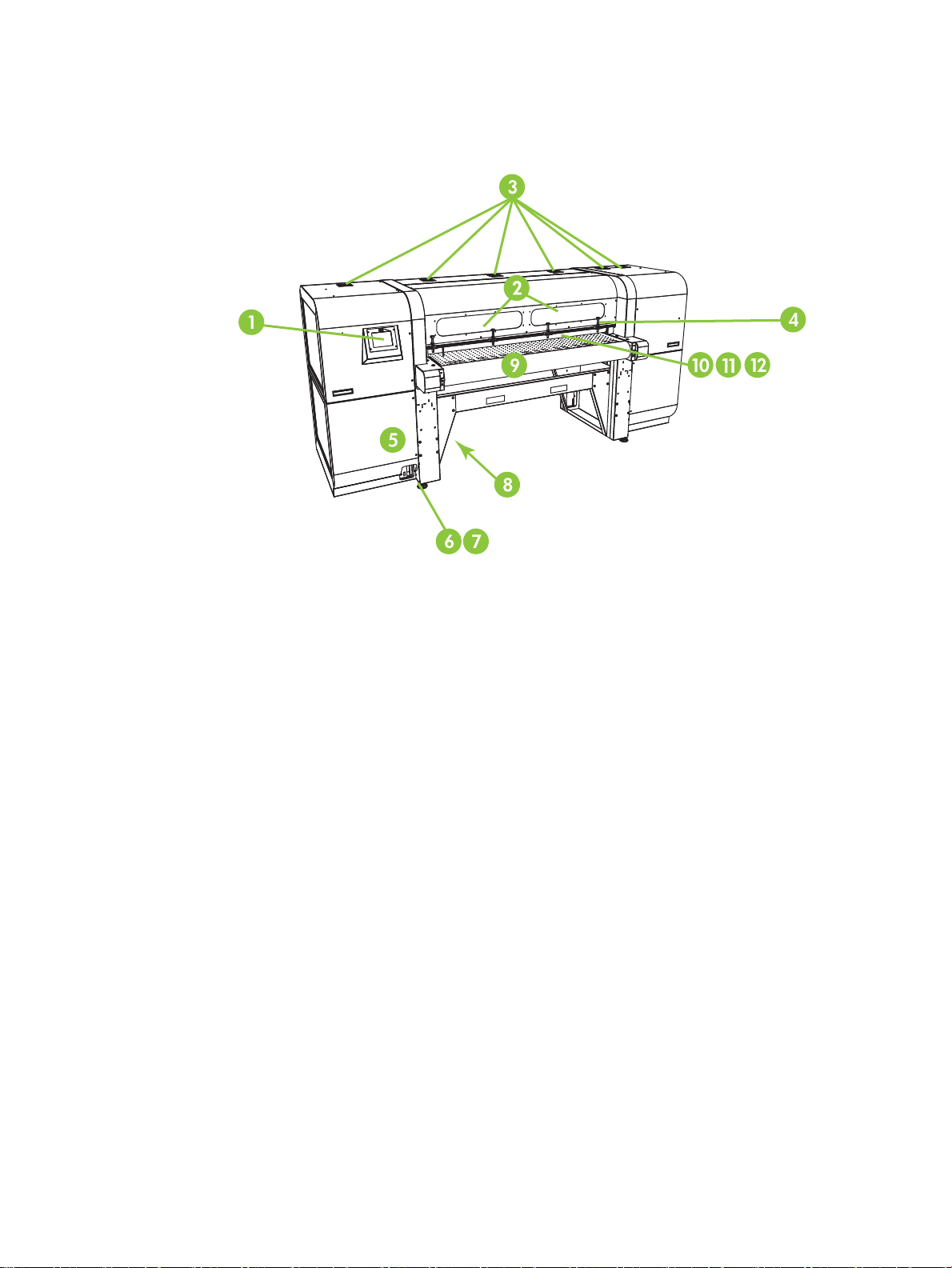
Figure 1-1 Input side
1. Touch-screen control panel
2. UV-filtered observation windows
3. Exhaust vents
4. Rigid media alignment pins
5. Electronics box (inside enclosure)
6. Data ports
7. Main power switch
8. Main power, takeup system power inlet ports, serial number and regulatory label (on lower enclosure)
9. Media drive belt
10. Media input roller (inside cover)
11. Media alignment bar (inside cover)
12. Media output roller (inside cover)
ENWW
Quick tour 5
Page 13
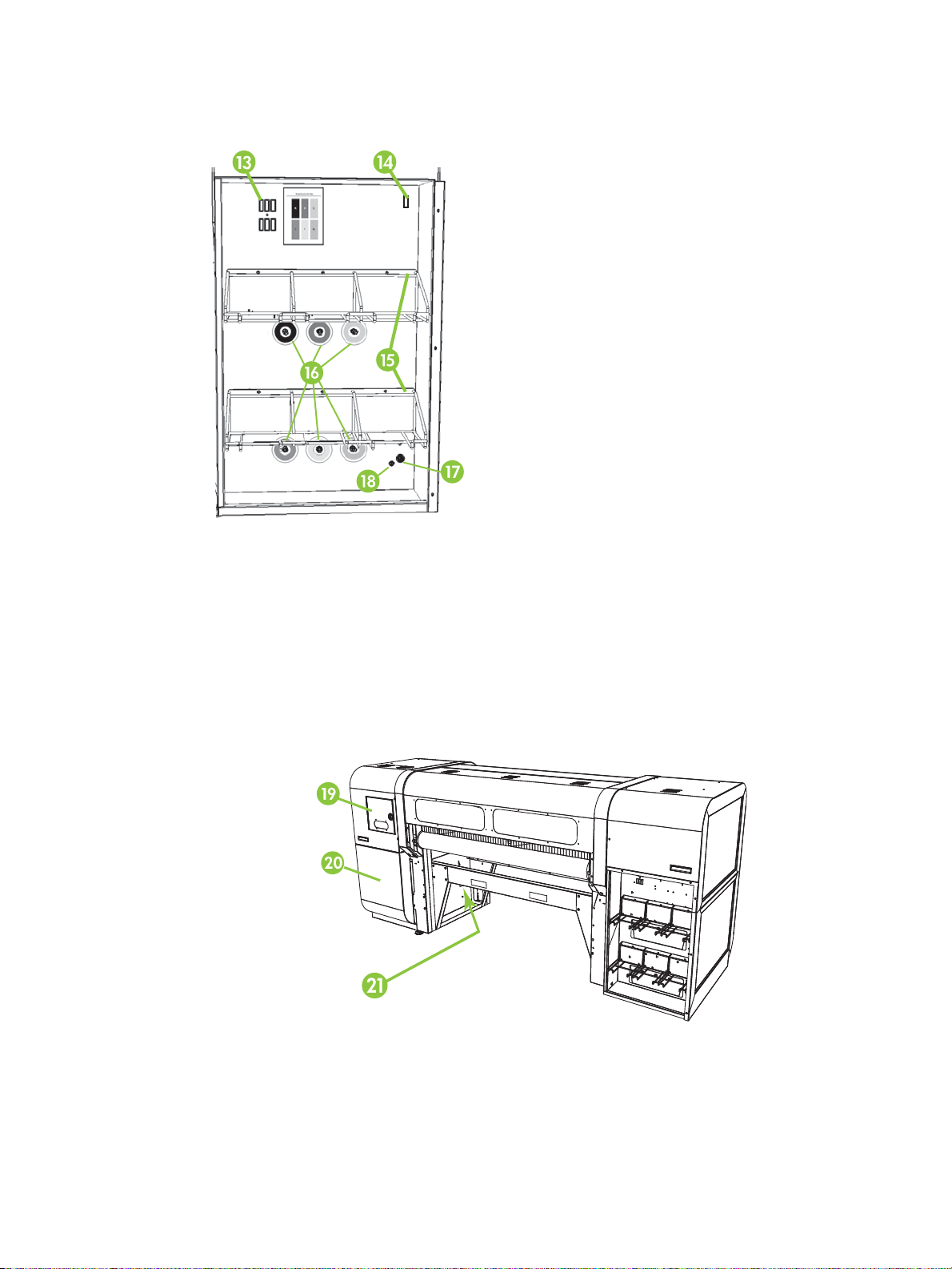
13. Profiler docking station
Figure 1-2 Ink supply compartment
14. Ink homogenizer power outlet
15. Ink supply rack
16. Ink connections
17. Vacuum system auxiliary power inlet
18. Vacuum adjustment knob (factory adjustment, do not change)
Figure 1-3 Output side
19. Service station and printhead carriage access door
20. Printhead maintenance vacuum (inside enclosure)
21. Waste ink spigot
Chapter 1 Introduction ENWW
6
Page 14

Special features
Printheads
●
Printheads — variable drop size, piezoelectric printheads.
Ink system
●
Off-Head System (OHS) — Bulk ink boxes with integrated filters. No-drip quick connectors simplify ink
box replacement.
●
Onboard vacuum system — Provides vacuum to maintain negative printhead pressure.
●
Patented automated printhead service station — Fully maintains the health of the printheads while idle
or in service, without operator intervention.
●
HP White Ink Homogenizer — Part of the optional white ink upgrade accessory kit, keeps white
pigments dispersed for optimal print quality. The white ink upgrade option and white ink cartridge are
required to print with white ink. See Order accessories on page 73 and Order ink supplies on page 24
for ordering information.
Media handling
●
Automatic head height — Printer automatically sets the correct head height above sheet-fed media.
●
●
●
●
●
Calibration
The printer uses a high-resolution digital imaging sensor (camera) and embedded software to align the
printheads, and to detect and replace missing jets. Manual and automatic calibrations are available.
●
●
Automatic media width sensing — Automatically detects the width and position of sheet-fed media, for
precise image placement (for detectable media, otherwise the manual method can be used).
Built-in static charge abatement — Ionizer bars help dissipate static electric charge from synthetic
media.
Rigid media tables feature a flip-up top for space-saving storage: it flips up for use, and down for
storage.
Optional extension tables can be added to the ends of the standard tables to handle longer sheets of
media. See Order accessories on page 73 for ordering information.
Optional roll-fed media supply and takeup system with table-top roll holder is available for handling
roll-fed media. See Order accessories on page 73 for ordering information.
AutoSet calibration — Automatically aligns printheads bidirectionally for precise positioning of inkjet
pixels, and runs AutoJet.
AutoJet calibration— Compensates for most lost or misfiring jets by locating them and using substitute
jets without slowing printing speed.
ENWW
Special features 7
Page 15

Performance and ease-of-use
●
Media Wizard — Stores and recalls a set of operating parameters by media type and print mode, for
optimal printing performance. Includes a set of predefined settings for standard media. You can also
create and save custom settings for other media.
●
Edge-to-edge printing — Provides the look of “full bleed” prints without trimming.
●
Stored jobs — Stores print jobs on the printer's internal hard disk drive for subsequent reprinting
without having to resend it from the RIP.
●
Simplified control panel interface — Touch-screen control panel with graphical interface presents
frequently-used functions. A menu provides access to less-frequently used functions and
troubleshooting help.
●
User assistance — Control panel features online help, interactive procedures, scheduled cleaning
reminders, and diagnostics to assist the user, reducing training and troubleshooting time.
●
HP Embedded Web Server — By entering the printer's IP address into the address bar of any web
browser on your local area network, you can view printer status, change certain settings, upgrade the
printer firmware, and download system log files.
Use the HP Embedded Web Server
When the printer is connected to your local area network (LAN), you can enter the printer's IP address into the
address bar of your web browser to display printer status, set the internal date and time of the printer,
download a log file, update the printer firmware, and transfer a custom Media Wizard definition.
Connect to the HP Embedded Web Server
To connect to the Embedded Web Server, open a web browser on any computer connected to the same
network as the printer, and enter the printer's IP address into the browser (http://[ip-address]). The printer's
IP address is displayed on the System screen of the printer's control panel. When the browser connects to the
printer, the Embedded Web Server displays its home page.
Display the printer status
To display the printer status, including media type loaded and amount of ink remaining, select the printer
status option from the Embedded Web Server menu.
Display the current control panel image
To display an image of the screen that is currently displayed on the control panel, select the option from the
Embedded Web Server menu.
Set the date and time
To set the printer date and time, select this option from the Embedded Web Server menu. Enter the current
date and time as specified on this screen, and click the Set Time button.
NOTE:
logs, verify the correct local time on the printer, and adjust as needed for daylight savings time changes if
observed at your location.
To ensure the proper scheduling of automatic maintenance operations and times and dates in event
8 Chapter 1 Introduction ENWW
Page 16

Download a printer events file
The printer maintains a continuous log of its operations and settings in plain text files, which it stores on its
internal hard disk drive. These files are useful for troubleshooting. To access these files, select the Get
Printer Events Files option from the Embedded Web Server menu. From the list of files, click the link to the
file you want to view or save to your computer.
Update the printer software
HP occasionally issues new versions of the embedded software (printer firmware). After obtaining an update
file, you can use the Embedded Web Server to install it onto the printer.
From the Embedded Web Server, select the Update Printer Software option from the menu. Follow the
onscreen instructions to upload and install the software update.
Transfer a custom media definition
The Media Wizard enables you to define custom media definitions, in addition to the standard definitions that
are supplied with the printer. You can use the Embedded Web Server to download a custom media definition
from a printer to your computer, then upload it to a different printer.
When you select Retrieve Custom Media File from the web server, the web server displays a list of custom
media definitions that exist on the printer. Select one of these definitions, and it is saved to your computer.
To send a custom media definition to a printer, enter its IP address into the web browser. When you choose
Select Custom Media File to Install from the web server, the web server prompts you to browse to and enter
the name of the file you want to send to the printer. When you click Send, the file is sent to the printer. After
the printer receives the file, it should be visible on the printer's control panel in the list of media.
Display job accounting information
Select Job Accounting to display information for each print job, such as date and time printed, and amount of
media and ink used.
Display printer usage data
Select Printer Usage to display the cumulative amounts of sheet-fed media, roll-fed media, and ink used for
the life of the printer.
ENWW Use the HP Embedded Web Server 9
Page 17

2 Configure and load media
●
Configure media
●
Work with the rigid media tables
●
Load rigid media
●
Load roll-fed media with table-top roll holder
10 Chapter 2 Configure and load media ENWW
Page 18

Configure media
Before the printer will accept a print job, it must be configured for a specific media type. The currentlyconfigured media type, if any, is displayed on the Home page of the control panel.
1. If the control panel displays the media type you intend to load, press Load and go to Load rigid media
on page 14. Otherwise, continue to the next step.
2. In the Activity Tray on the control panel, press the Media icon. The Media screen appears.
See Use the control panel on page 34 for a complete description of the control panel screens and
options.
3. Press Configure.
The Select Media to Load menu appears.
4. Press a media name, or Create Media Type.
The list of media types ends with the option Create Media Type (page down to the end of the list by
pressing the page down button).
●
If you press a media name, a list of settings appears for you to review. See Media Wizard
on page 11 for a description of the settings.
●
If you press Create Media Type, the control panel prompts you to select a standard media type to
use as a starting point for the new media type settings. After you select a standard media type, the
control panel prompts you for a name for the new media type, then a list of settings appears for
you to review and change if necessary.Media Wizard on page 11 for a description of the settings.
5. Review and change (for previously-created custom media types only) the media settings as needed.
6. Press Out or Proceed once or twice until the printer displays the prompt “Load media now?”
7. Press No to save your configuration and cancel the load process, or press Yes and proceed to Load rigid
media on page 14 or Load roll-fed media with table-top roll holder on page 19.
NOTE: When you create a custom media type on the printer, in order to print on the new media type, you
must also add the new media type using Media Manager for the Onyx RIP, or EasyMedia for the Caldera RIP.
Refer to the documentation for your RIP for instructions.
Media Wizard
To view or delete settings for an existing media type, press Media > Wizard. The Media Wizard also lets you
create a media type without configuring it as the currently-loaded media.
For each media type, the Media Wizard stores the following settings (as indicated, some settings apply to
either roll-fed or sheet-fed media only):
●
General Media Settings
TIP: Start by using one of the standard media types. If you are not using a standard media type,
select the standard media type that most closely matches the media you are using. Then only if
necessary, create a new media type using the standard type you selected as a starting point, and
adjust it as needed.
ENWW
Configure media 11
Page 19

To change the general media settings, press Media > Wizard > Create Media Type > Proceed > select
closest media type > Proceed > enter media name > Proceed > Proceed > Yes > Change General Media
Settings.
◦
Vacuum Fan Level — Adjusts the amount of vacuum at the media drive belt. Observe the media as
the fan speed changes. If the media is lifting off the belt, increase the fan speed. If the media
advance seems impeded by the vacuum, decrease the fan speed.
◦
Feed Method — Roll-fed (with optional supply and takeup system installed) or Cut Sheet.
◦
Weight — Sets the media belt drive motor and media advance amount to handle Light (up to 22
kg (50 lb)) or Heavy (22–113 kg (50–250 lb)) media.
CAUTION: The input and output tables are rated at a maximum load of 68.0 kg (150 lb). Do not
exceed this maximum load.
◦
Misc Settings
●
Use Rollers — Sets whether the Input and Output media rollers are used (Yes) or not used
(No) with the Flat Media setting (see Load rigid media on page 14). When set to Yes, the
rollers will move up or down as needed to be just above the surface of the media. When set
to No, the rollers will move to their highest point and remain there.
●
Detectable to Printer — If Yes, the media sensor and image sensor will be used. If No, the
media sensor and image sensor will not be used (with clear films, for example).
●
Conductive — Sets whether the ionizer bar is used.
●
Print Mode Specific Settings — For custom media types, this screen enables you to adjust the settings
for each print mode and color set combination. See Available print modes on page 26 for a detailed
description of print modes and color sets.
To change the print mode specific settings, press Media > Wizard > Create Media Type > Proceed >
select closest media type > Proceed > enter media name > Proceed > Proceed > Yes > View Print Mode
Specific Settings.
◦
Print Mode — Select the print mode whose settings you want to change.
◦
Color Set — Select the color set whose settings you want to change.
◦
Change Print Mode Specific Settings — Change settings for the print mode and color set you
selected.
●
Select UV Lamp Power — A high lamp power setting increases ink curing power, important at
high speeds and for older lamps that are losing their intensity; a low setting for newer lamps
extends their life.
Closing the shutter on the trailing lamp blocks the UV light from the lamp, which allows the
drop of jetted ink to spread out more before it is cured, resulting in a glossier look to the
print. The color profile used must take this into account for accurate color matching.
●
Select Print Delay — A longer printing delay helps dissipate heat from heat-sensitive
substrates, while a shorter delay speeds printing throughput.
Chapter 2 Configure and load media ENWW
12
Page 20
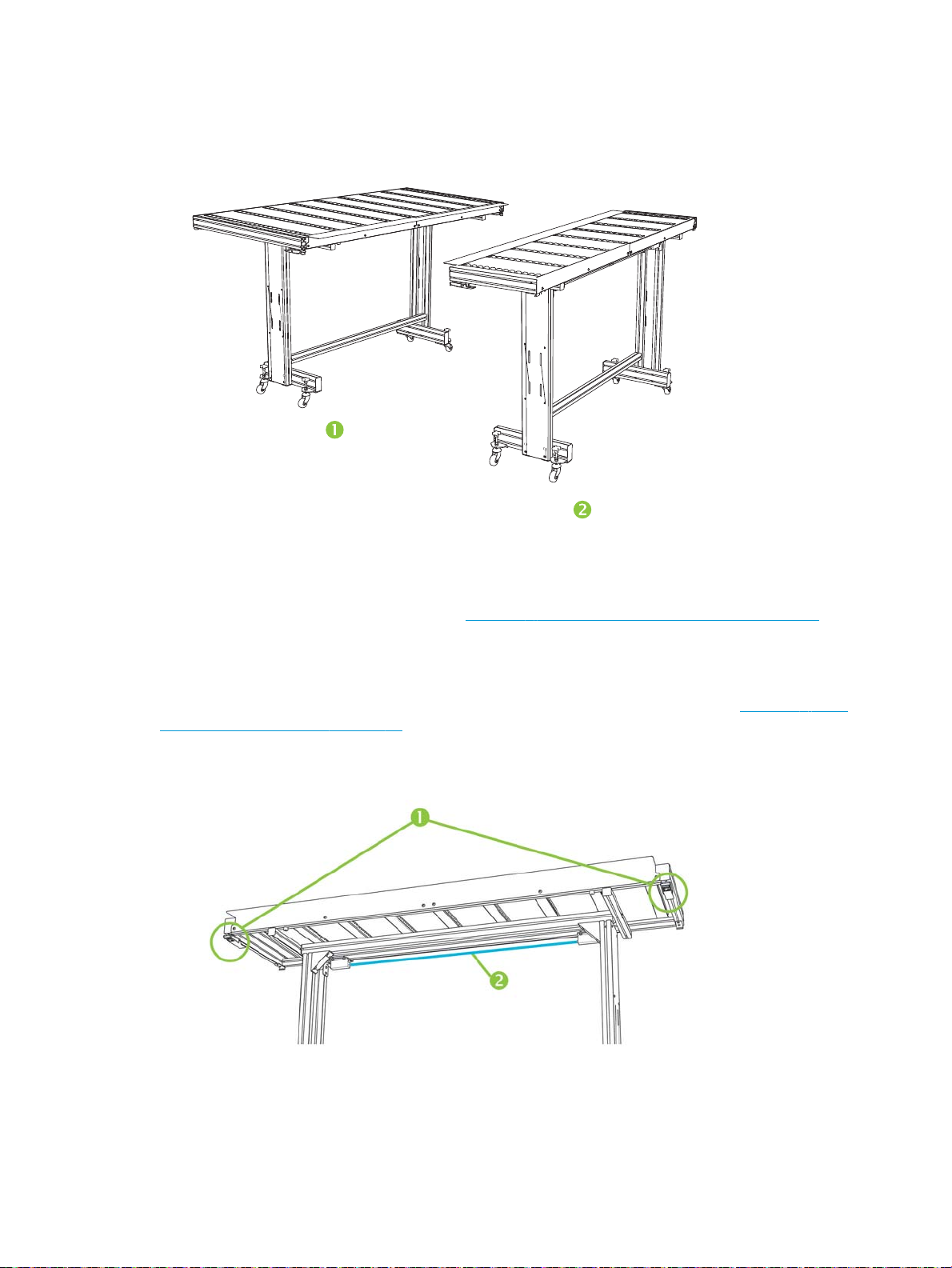
Work with the rigid media tables
Figure 2-1 Output (1) and input (2) tables
The printer includes a set of standard input and output tables for rigid media handling: one for the input side
of the printer, and one for the output side. These tables are assembled, installed and leveled when the
printer is installed. The tables are designed to be used only when the tabletop is in the horizontal position
and latched to the printer. The latches, see (1) Figure 2-2 Table latches and release cable on page 13, are
needed for safety, print quality, and to provide a ground path to discharge the electrostatic charge from
synthetic media.
The tabletop can be pivoted to a near-vertical position to save space during storage. After detaching the
tables from the printer, release the tabletop latches by pulling the release cable, see (2) Figure 2-2 Table
latches and release cable on page 13, under the tabletop. To return the tabletop to its operating position,
pivot the table top down and press down firmly to engage the latches.
Figure 2-2 Table latches and release cable
Optional extension tables are also available as accessories. When properly assembled and attached to the
ends of the standard tables, the extension tables enable safe and reliable handling of large media sheets.
During use, the extension tables must be latched to the standard tables for safety, print quality, and to
provide a ground path to discharge the electrostatic charge from synthetic media. When not attached to the
ENWW
Work with the rigid media tables 13
Page 21

standard tables, the extension table tops are designed to pivot into the storage position under their own
weight.
CAUTION: The standard and accessory extension tables are intended for use only when attached to the
printer as described in these instructions. When not in use, the tables should be stored with the table tops
folded in the storage position. Use caution when operating the table tops and moving the tables, to avoid
personal injury or damage to property.
NOTE: If the accessory tables were properly leveled when they were installed, they should not have to be
leveled again. If sheet-fed media feed problems occur, make sure the accessory tables are securely latched
to the standard tables, and verify that the tables are level. Check for level over the fixed support assembly
first, then over the folding support, and adjust the table wheels up or down as necessary.
Load rigid media
NOTE: See Table A-2 Media sizes on page 104 for a list of supported media sizes.
1. If the rigid media tables are not already installed, position the input and output tables at each end of the
media drive belt, and engage the attachment latches to the printer. Make sure that the pivoting table
tops are securely latched in the operating position.
NOTE: If you have the optional roll-fed media accessory installed, remove the foam press rollers. The
foam press rollers are not used with rigid media.
2. At the end of the Configure Media process (see Configure media on page 11), press Yes on the control
panel; or press Home > Load Media.
Before you can load, you must configure the media as explained in Configure media on page 11.
3. Select one of the following media rollers options, then press Proceed:
●
Flat Media — If the rollers were set to “Yes” in the media configuration (see Configure media
on page 11), the rollers will move up or down as needed to be just above the surface of the media.
If the rollers were set to “No”, the rollers will remain at their highest point and will not be used. In
either case, the full imageable length of the sheet is available for printing.
●
Warped Media, Hold Down — When a sheet is loaded, the leading edge is advanced so that it is
underneath the output roller. Printing is allowed only until the trailing edge of the sheet has
reached the input roller. The imageable area of the sheet is reduced by 65.4 cm (25.8 in) from both
the leading and trailing edges.
●
Short Media — Enables printing on sheets that are not long enough to reach the output roller and
thickness sensor at the same time. The media length must be at least 22 cm (8.5 in).
NOTE: The media rollers are lowered to just above the media with any force or pressure, other than
their own weight. They are designed to hold down lighter weight media with at most a moderate
amount of warping. They may have no effect on heavier, badly warped media. For best results, use the
flattest available media.
4. Select the approximate thickness or enter the exact thickness of the media you are loading, then press
Proceed.
5. Load the sheet of media onto the input table, sliding it forward against the media alignment bar (under
the printhead carriage rail), then left along the media alignment bar until the media touches the
leftmost alignment pin.
Chapter 2 Configure and load media ENWW
14
Page 22

6. Press Sheet Ready on the control panel, or Cancel to cancel the media load process.
TIP: Before you press Sheet Ready, you can press Turn On Lamps on the control panel to initiate their
warm-up cycle while you complete the subsequent steps in the load process. This will enable printing to
begin sooner than if you allow the lamps to be turned on automatically. You can also change the head
height at this time.
7. Enter the number of sheets:
●
Single sheet
●
N-UP Sheet Feed (Same Dimensions) — For two or more sheets of the same size loaded at once
across the width of the printer
●
N-UP Sheet Feed (Different Dimensions) — For two or more sheets of different sizes loaded at
once across the width of the printer
8. Select the media length from the list, or enter a length manually, then press Proceed.
The printer measures the media, and the control panel displays a summary screen of the settings you
specified.
9. Press Proceed to confirm that the media has loaded.
The Home page appears.
10. Send a print job from the RIP or print a Stored Job from the printer.
For multiple copy jobs ejected to the output side of the printer, the printer control panel will prompt for
the next sheet a short time before the previous sheet is done printing. Load the subsequent sheet
against the media alignment bar, and press Sheet Ready on the control panel. The printer prints on the
next sheet and will use the same option settings on all of the copies in the print job.
Use the camera to locate the sheets
The on-carriage camera is used to locate the position of each sheet as part of the load process. To specify
load options:
1. On the Printing page, press Options.
2. From the Options menu, press Measure Media.
The Measure Media Frequency menu appears:
●
Measure only on first load — Only the first row is measured, and those measurements are used for
all subsequent rows. Use the alignment pins to locate the sheets in subsequent rows. This speeds
throughput by eliminating the measurement step for each row.
●
Measure on all loads — Each sheet in every row of sheets will be measured, and reported to the
server. This aids in accurate placement of edge-to-edge images. In this mode, use of the
alignment pins is unnecessary.
●
Don't measure media — Does not measure the sheets, for fastest throughput. Use only if there
are wide margins on all four sides, or for transparent media, which the printer cannot detect. Use
the alignment pins to locate the sheets.
ENWW
Load rigid media 15
Page 23

3. Press a Measure Media option.
When you select a Measure Media option, the Measure Media Type menu appears. This enables you to
select a trade-off between image placement accuracy and throughput.
●
Minimal — Measures the media width once, locates leading edge near the user side on subsequent
loads.
●
Standard — Measures the media width once, estimates skew by locating the leading edge near the
user and service sides on subsequent loads.
●
One Edge — On first load, measures both edges; on subsequent loads, measures the left edge
only.
●
Maximal — On every load, measures the media width at two points to estimate skew, finds the
leading edge near the user side.
If the print job has wide margins, you can increase throughput with Minimal or One Edge. For edge-toedge printing, increase accuracy by selecting Standard or Maximal.
4. Press a Measure Media Type option.
After you select a Measure Media Type option, a message appears to remind you to load the same
number of sheets with every N-UP group, until they have all been printed. Press Proceed to dismiss this
message and return to the printer options menu.
Quick Load
After printing is complete, you can reload a sheet of the same media type and dimensions without
reconfiguring the media. Use Quick Load or Load:
NOTE: This option is available if you select Measure only on first load from the Measure Media Frequency
menu (see Use the camera to locate the sheets on page 15).
1. Press Load on the Home Page screen.
2. Place the media onto the media drive belt, and push it flush against the media alignment bar, then left
3. Press Sheet Ready on the control panel.
The control panel displays a menu with a Quick Load and Load option.
●
To load a sheet of media with the same media type with the same dimensions as the previous job,
press Quick Load.
●
To load a sheet of media with the same media type with the same dimensions as the previous job,
but different flatness, thickness, or number of N-UP sheets, press Load. The control panel allows
you to respecify these options.
along the media alignment bar until it touches the leftmost alignment pin.
At this point, the control panel allows you to adjust the vacuum fans and head height off the media.
The printer is ready to receive the next job from the RIP or Stored Jobs on the printer.
Chapter 2 Configure and load media ENWW
16
Page 24

Multi-sheet N-Up
Multiple-sheet N-Up allows you to print more than one copy of a single job or multiple jobs on multiple
sheets across the belt of either the same or different dimensions, using multiple rows of sheets until the job
is complete. Use the built-in media alignment pins for quick positioning of the sheets across the printer’s
width. Align the left side of each sheet with one of the pins, with a small space from the right edge of the
sheet to the next pin, to allow for variations in sheet dimensions. Alternatively, if you position the pins with
zero clearance between the sheets and each pin, before each print be sure to raise the pins over the thickness
of the sheets; otherwise the sheets could become skewed.
NOTE: When printing multi-sheet N-Up on media that cannot be detected by the printer's media sensor
(black, dark colored, reflective, or clear), the sheets in each row must be spaced equally.
This type of printing works best with an image that has wide margins on all four edges, but edge-to-edge
printing is also possible by carefully matching the dimensions of the image(s) to the dimensions of the media
sheets. Margins can be defined by the RIP or can be set and adjusted on the printer.
To enable, select one of the N-Up Sheet Feed options when loading media and have the number of sheets
you intend to print across the width of the printer in position to be loaded. Sheets must not be more than 7.6
cm (3 in) apart from each other. Use the alignment pins if you will be printing multiple rows.
ENWW Load rigid media 17
Page 25

Table 2-1 Supported sheet configurations
Single image Multi-image Remaining copy 2-sided Nesting Eject settings
Single sheet Yes (N copies) No Yes Yes Yes Input, Output,
Off
Multi-sheet
(same
dimensions)
Multi-sheet
(different
dimensions)
Yes (N copies) Yes Yes Yes No Input, Output
Yes Yes No No No Output
Multi-sheet printing (same dimensions)
Multiple copies of a single image can be made by setting the quantity to a number equal to or greater than
the number of the sheets you loaded. The printer prompts you to load more sheets until the number of
copies you specified has been printed. You can print any number of copies in this configuration, even if the
total number does not divide evenly into the number of sheets per row. Only the last row may have a
different number of sheets.
The Multi-Image feature is enabled by selecting the Print 2-Sided / Multi Image N-Up button in the lower
right corner of the Stored Jobs screen, then selecting Multi-Image N-Up in the following screen. Each of the
jobs across the belt can be different jobs, but all jobs must have the same color set and resolution. Once the
first job is selected, the printer displays jobs with a color set or resolution mismatch with a red border. If a
different print mode is desired, or if separate jobs have different print modes but share the same resolution,
a single print mode is changeable by selecting Print Mode in the summary screen. Enter the number of image
groups or ‘rows’ to be printed and press Proceed.
Multi-sheet printing (different dimensions)
As with multi-sheet printing with the same dimensions, multiple copies of a single image can be made by
setting the quantity to a number equal to or greater than the number of the sheets you loaded. Because
Chapter 2 Configure and load media ENWW
18
Page 26

sheets can be of different sizes, and the image of a single size, be careful about job alignment and
overprinting onto the belt.
Again, as with multi-sheet printing with the same dimensions, the Multi-Image feature is selected from the
Stored Jobs screen, following the same process. Because sheets can be of different sizes, and the images of
various sizes, be careful about job size and alignment when selecting jobs.
Load roll-fed media with table-top roll holder
If the optional roll-fed media supply and takeup system with table-top roll holder is installed on the printer,
you can print on roll-fed media in the following way.
NOTE: See Table A-2 Media sizes on page 104 for a list of supported media sizes.
1. If installed, detach the rigid media output table from the printer, and set it aside.
2. Install the table-top roll holders into the holes on the input table, allowing the media to be loaded
centered on the printer.
3. Load media onto the table-top roll holder, spooling off the top, with the media centered.
NOTE: The table-top roll holder supports only print side out.
NOTE: To prevent fingerprints from showing on printed output, wear gloves while handling the media.
4. Configure the media as explained in Configure media on page 11. At the end of the Configure Media
process, press Proceed on the control panel.
OR
If the media is already configured, from the Home page of the control panel, press Load.
NOTE: Be sure to enter the correct media thickness. The printer can detect the thickness of sheet-fed
media only if the media is loaded under the media thickness sensor, which is located at the user end of
the carriage rail. For roll-fed media (if enabled), use the manufacturer's specification or use a caliper to
measure the thickness.
5. As prompted by the control panel, ensure that only a single foam roller is being used and is in the
storage position. Pull media from the spool and feed it into the printer, use the forward and backward
buttons and fans on and off selector on the control panel to assist. Then press Proceed.
6. Place the foam roller into its operating position and advance the media past the output roller. Then
press Proceed.
7. Return the foam roller to its storage position, ensure that the vacuum fans are off and hold the Advance
Media button for several seconds to assist in media tracking. Press Proceed to continue.
8. Place the foam roller into the operating position and make any final positioning adjustments. Press
Proceed.
9. On the Select Thickness Units screen, press the option that corresponds to the units you will use.
ENWW
Load roll-fed media with table-top roll holder 19
Page 27

10. Enter the media length or press Cancel for an undefined length.
The printer measures the media width.
11. On the Front Page screen, press Proceed.
The Front Page screen appears on the control panel.
Use the camera to locate the media
For roll-fed media, you can choose between two levels of precision for finding the left (user end), and right
(service end) edges of the media.
1. On the Printing page, press Options.
2. From the Options menu, press Measure Media.
The Measure Media Frequency menu appears. This enables you to select a trade-off between image
placement accuracy and throughput.
●
When loading — Locates the left and right edges only when loading a roll of media.
●
Before each copy — Locates the left and right edges of the media before each print. This enables
the printer to compensate for any “drifting” of the media, and print the image at the correct
location.
Check Media Skew — the printer measures the skew of the media when measuring the width
when the media is loaded or reloaded. The feature is disabled when Before each copy is enabled.
3. Press a Measure Media Type option.
The Options menu reappears.
20 Chapter 2 Configure and load media ENWW
Page 28

3 Load inks
●
Load inks
●
Order ink supplies
NOTE: UV inks have a limited shelf life. The Warranty Ends date listed on the ink box label should be taken
into account when ordering inks, rotating ink in inventory, and planning print jobs. Printing with an ink supply
after this date may result in substandard image quality.
ENWW 21
Page 29
Load inks
The amount of ink in the ink supply box is tracked by the printer software and recorded on its corresponding
profiler. The control panel displays a bar graph with the ink levels in each ink box. When the control panel
shows that the ink is low, replace the ink box with a full ink box of the same color, and replace the profiler.
NOTE: You may want to wear gloves (latex or nitrile) and have a paper towel handy to catch the drops of ink
that may fall from the ink tube connection during this procedure.
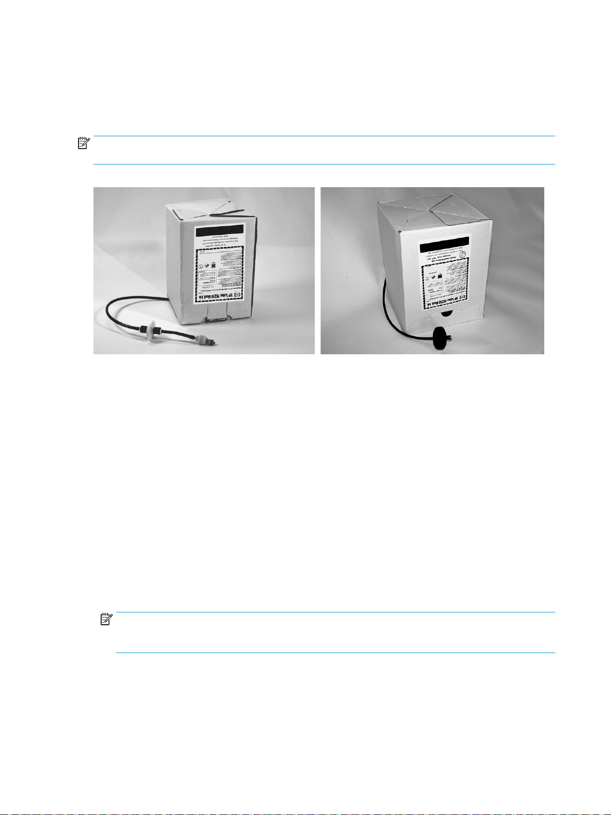
Figure 3-1 Ink boxes (both styles of connectors can be used with the printer)
Unload an empty ink box
1. Remove the profiler.
2. Lift the box out of its holder and turn the box upside down so the ink tube is pointing up.
3. Grasp the metal connector where the ink tube enters the printer, and push it up to release the ink
supply tube.
4. Remove and dispose of the ink box (refer to the Material Safety Data Sheet for proper disposal
procedures).
Load a full ink box
1. Open the new ink box and locate the supply connector.
2. Locate and remove the profiler, and set aside until step 5.
3. Shake, invert and install the ink box into position in the holder, so the ink supply tube is at the bottom of
the box.
NOTE: The pigments in the inks can settle to the bottom of the ink box during storage. To reduce
inaccurate color in prints, invert and vigorously shake the ink box for at least one minute before
installing it into the printer.
22 Chapter 3 Load inks ENWW
Page 30

4. Insert the ink tube connector into the metal connector on the printer.
The position for each ink color is shown on a label below each ink box and next to the profiler docking
station. The white ink box has a split “Y” supply line that connects the box to two ink ports on the
printer (Light Cyan/White and Light Magenta/White).
5. Install the profiler in the corresponding docking station slot.
NOTE: Printing with white ink requires you to install the optional White Ink Upgrade Kit and then perform a
white ink conversion. See Order accessories on page 73 for ordering instructions.
ENWW Load inks 23
Page 31

Order ink supplies
You can order the following ink supplies for your printer.
Table 3-1 Ink cartridges
Cartridge Part number
HP FB250 3L Cyan Scitex Ink Cartridge CH216A
HP FB250 3L Magenta Scitex Ink Cartridge CH217A
HP FB250 3L Yellow Scitex Ink Cartridge CH218A
HP FB250 3L Black Scitex Ink Cartridge CH219A
HP FB250 3L Light Cyan Scitex Ink Cartridge CH220A
HP FB250 3L Light Magenta Scitex Ink Cartridge CH221A
HP FB251 2L White Scitex Ink Cartridge CQ123A
HP FB794 3L Cyan Scitex Ink Cartridge G0Y93A
HP FB794 3L Magenta Scitex Ink Cartridge G0Y94A
HP FB794 3L Yellow Scitex Ink Cartridge G0Y95A
HP FB794 3L Black Scitex Ink Cartridge G0Y96A
HP FB794 3L Light Cyan Scitex Ink Cartridge G0Y97A
HP FB794 3L Light Magenta Scitex Ink Cartridge G0Y98A
Table 3-2 Cleaning supplies
Printhead flush Part number
HP UV Printhead Flush CH122A
24 Chapter 3 Load inks ENWW
Page 32

4 Printing jobs
●
Available print modes
●
Stored jobs
●
Position and eject options
●
Printing tips
ENWW 25
Page 33

Available print modes
You select a print mode for each print job at the external RIP. Refer to the RIP documentation for instructions.
Stored jobs can be printed in the mode originally specified by the RIP, or in any other mode at the same
resolution as it was sent from the RIP.
The printer can print in several different modes for the combination of image quality and speed that you
require. The modes are named after their intended applications. The higher-quality modes are meant for
closer viewing. The faster modes are meant for viewing from longer distances. Maximum speeds shown in
the table are for jobs with six colors, four colors, or four colors plus white spot printing. White flood fills print
at approximately 45% the other color modes.
NOTE: Printing with white ink requires you to install the optional White Ink Upgrade Kit and then perform a
white ink conversion. See Order accessories on page 73 for ordering instructions.
Table 4-1 FB550 print modes and maximum print speeds
Print mode Maximum speed,
CMYKcm, CMYK, CMYK+W
Spot
Photo Plus: Near offset quality, saturated colors, backlit applications
1
Viewing distance: Less than 1 m (3 ft)
Photo: Photo gloss, saturated colors, backlit applications
2
Viewing distance: Less than 1 m (3 ft)
Indoor Signage Plus: Higher quality point-of-purchase (POP)
3
Viewing distance: 1–2 m (3–6 ft)
Indoor Signage: Standard point-of-purchase (POP)
4
Viewing distance: 1–2 m (3–6 ft)
Outdoor Signage Plus: Medium viewing distance signage
5
Viewing distance: 2–3 m (6–10 ft)
Outdoor Signage: Longer distance viewing signage (not available for
white ink jobs)
6
Viewing distance: 3–5 m (10–16 ft)
Express: Very long distance viewing (not available for white ink jobs)
7
Viewing distance: Greater than 5 m (16 ft)
4.6 m²/h (50 ft²/h) 2.8 m²/h (30 ft²/h)
9.2 m²/h (99 ft²/h) 4.2 m²/h (46 ft²/h)
12.6 m²/h (135 ft²/h) 5.6 m²/h (60 ft²/h)
18.5 m²/h (199 ft²/h) 8.6 m²/h (93 ft²/h)
22.4 m²/h (241 ft²/h) 9.3 m²/h (100 ft²/h)
31.5 m²/h (339 ft²/h)
38.9 m²/h (419 ft²/h)
Maximum speed, white
flood
26 Chapter 4 Printing jobs ENWW
Page 34

Figure 4-1 Quality and speed of each print mode (FB550)
m²/h (ft²/h)
Q
Table 4-2 FB750 print modes and maximum print speeds
Print mode Maximum speed,
CMYKcm, CMYK, CMYK+W
Spot
Photo Plus: Near offset quality, saturated colors, backlit applications
1
Viewing distance: Less than 1 m (3 ft)
Photo: Photo gloss, saturated colors, backlit applications
2
Viewing distance: Less than 1 m (3 ft)
Indoor Signage Plus: Higher quality point-of-purchase (POP)
3
Viewing distance: 1–2 m (3–6 ft)
Indoor Signage: Standard point-of-purchase (POP)
4
Viewing distance: 1–2 m (3–6 ft)
Outdoor Signage Plus: Medium viewing distance signage
5
Viewing distance: 2–3 m (6–10 ft)
Outdoor Signage: Longer distance viewing signage (not available for
white ink jobs)
6
Viewing distance: 3–5 m (10–16 ft)
Express: Very long distance viewing (not available for white ink jobs)
7
Viewing distance: Greater than 5 m (16 ft)
5.2 m²/h (56 ft²/h) 3.1 m²/h (34 ft²/h)
10.3 m²/h (110 ft²/h) 4.7 m²/h (51 ft²/h)
14.3 m²/h (154 ft²/h) 6.4 m²/h (69 ft²/h)
22.1 m²/h (227 ft²/h) 9.9 m²/h (106 ft²/h)
25 m²/h (269 ft²/h) 10.4 m²/h (112 ft²/h)
35.3 m²/h (380 ft²/h)
43.6 m²/h (469 ft²/h)
Maximum speed, white
flood
Billboard: Billboards, far away (not available for white ink jobs)
8
Viewing distance: Far away
85 m²/h (915 ft²/h)
ENWW Available print modes 27
Page 35

Figure 4-2 Quality and speed of each print mode (FB750)
m²/h (ft²/h)
Q
Stored jobs
When you send a print job to the printer, you can save the job automatically on the printer’s hard disk drive,
on a rotating first-in-first-out (FIFO) basis. You can “lock” a job to prevent it from being rotated out, but this
reduces the amount of space available for subsequent jobs to be saved. You can also save a stored job
without printing it until you print it from the control panel, or only print the job without saving it.
The printer can store up to 96 sheet-fed or roll-fed jobs. These jobs are retained on the printer's disk, even
when the printer power is cycled on and off. When the number of stored jobs reaches the printer's storage
capacity, subsequent print jobs will be printed but not stored.
If a job is too large to be saved, it is simply discarded from memory after printing. If a complete print job has
been received from the RIP and you cancel the print, it will still appear in the Stored Jobs listing.
Stored jobs can be viewed and managed from the control panel.
Thumbnail screen
To print or manage stored jobs, press Jobs on the Home or Printing page. On this page, you can view
thumbnail images of the various jobs. Locked jobs (protected from automatic deletion) are identified by a
padlock icon on the thumbnail image.
From the Stored Job thumbnails screen, you can perform these operations on the print job:
●
Press Set Filter to set a filter.
●
Press Multiple Select to select multiple jobs for a subsequent operation.
●
Press Information for the following kinds of information.
◦
Press Max Sizes to view the total image area that can be stored at each combination of resolution
and color set.
◦
Press History to view a log of stored jobs activity.
●
Press Settings to specify how jobs are stored and printed. These settings are saved even when the
printer is restarted.
Chapter 4 Printing jobs ENWW
28
Page 36

◦
Press Job Storage Mode to choose whether jobs are printed and/or saved.
●
●
●
◦
Press Job Storage Sorting to choose how jobs are sorted.
●
Press 2-Sided / Multi Image N-Up to set up a two-sided or multi-image N-Up print job using stored jobs.
The printer prompts you to select the stored jobs that you want to use. All jobs must have the same
color set and resolution.
When printing two-sided, side one of the sheet is ejected to the input side of the printer, and you are
prompted to flip over and reload the sheet to print side two. After printing, the sheet is ejected to the
output side of the printer.
TIP: When printing a two-sided print job from the stored jobs on the printer, and the Auto Eject
feature is disabled (set to “Off” under Printing page > Options > Eject Settings), Auto Eject is enabled
or the printer prompts you to change the Print Position setting before printing proceeds. This is because
double-sided printing by definition uses the Auto Eject feature. If necessary, you can print the sides as
two single-sided jobs, turning the sheet over between sides.
Properties screen
Print & Save — Prints the job and saves it to disk.
Save Only — Saves the job to disk without printing it. In this mode, the background color of
the Stored Jobs section on the Home Page screen turns green.
Print Only — Prints without saving the job to disk.
To view the properties of a Stored Job, or to print a Stored Job, press the job's thumbnail image. From the
Stored Job properties screen, you can perform these operations on the print job:
●
To print the job, press Load & Print. The printer will prompt you for the number of copies to print. If you
have multiple sheets loaded, each copy will print on a separate sheet, and the printer will prompt for
additional sheets until the number of copies requested have been printed. You can print the job in any
print mode that use the same resolution as the original job.
●
To adjust the right, left, leading, or trailing margins, press Margin Settings. The leading and trailing
margins are applied to sheet-fed and roll-fed print jobs.
●
To change the print mode of a job, press Print Mode. You can only change the mode to one that uses the
resolution at which the job was RIPed. To print the job at a different resolution, re-send the job from the
RIP at the new resolution.
●
To delete the job, press Delete.
●
To lock or unlock the job, press the appropriate button. Locking a job prevents it from being deleted, but
subtracts from the available memory for Stored Jobs.
TIP: If you want to print on a media type that is different from the media specified in a Stored Job, or if you
will re-linearize the printer, do not reprint the Stored Job. For the best color, re-send the job from the RIP
instead.
When printing a job, the printer checks that the currently loaded media matches the media type that was
loaded when the job was stored. If different, a warning is raised. You can choose to not print the job, or ignore
the warning and print anyway.
Printing on a media type or in a print mode that is different from the original job may result in a color shift.
ENWW Stored jobs 29
Page 37

TIP: While a print job is being received by the printer and saved to its internal hard disk (a process called
“spooling,”) you can switch the UV lamps on or off as desired, rather than wait for the entire job to be
spooled.
Position and eject options
The sheet-fed printing option Position/Eject, on the Printer Options menu, enables you to control how
images are positioned and whether the automatic sheet eject feature is enabled. By selecting Auto Eject Off,
you can save media by combining print jobs that are smaller than the sheet size onto the same sheet, instead
of on separate sheets. In this mode, you can print the jobs one after the other, or “nest” them across the
width of the media in rows. Position/Eject is available when the printer is configured for sheet-fed media.
●
Position options — For print jobs with a width that is less than the width of the media, you can control
where the image is positioned (flush left, flush right, centered, or nested).
●
Eject options — For sheet fed jobs, you can control whether the media is ejected after each job to the
output side, input side, or not automatically ejected (Auto Eject Off).
●
Nested output — When you set Eject to Auto Eject Off, and Position to Nested, the print jobs are nested
onto the media until all jobs are printed or there is no more room on the sheet.
Figure 4-3 Position options with Auto Eject Off
Printing tips
CAUTION:
environments with low relative humidity. This charge can pose an electrostatic discharge (ESD) hazard to
persons, the printer, and other equipment. It can be safely discharged by draping a grounded chain or tinsel
over the top of the media, or by wiping the media with a solution of 90% isopropyl alcohol and allowing it to
dry for five minutes before printing. A relative humidity of 40%-60% will greatly reduce problems with static
electricity.
30 Chapter 4 Printing jobs ENWW
Synthetic media commonly used for inkjet printing can build up a static charge, especially in
Page 38

●
Rigid cut-sheet media — Use only flat, unwarped, undamaged sheets, with parallel opposite edges and
90° corners. For optimal image quality, use smooth-surfaced media. Images printed on porous media
will lack fine detail.
●
Curing continues for 24-48 hours — The UV ink will continue to cure for a day or two after printing.
Maximum durability and adhesion is achieved when the ink is fully cured.
●
If you print on the media drive belt, clean the ink off the belt as soon as possible. The longer that ink
remains on the belt, the more difficult it is to remove. To remove ink from the belt, moisten the ink with
isopropyl alcohol, let stand for a few minutes, and wipe with a paper towel. Carefully remove any flaked
ink from the area.
●
To avoid printing on the media drive belt when printing edge-to-edge (0 margin) jobs, you can affix
dark-colored masking tape on the belt where the sides of the media will be. Remove or replace the tape
periodically as ink accumulates on the tape.
●
Do not attempt to adjust the vacuum level for the printheads. It has been factory adjusted for best
performance.
●
Printing on reflective media will reflect UV light onto the printheads, which will cure the ink over time
and clog the ink jets. To minimize this:
◦
Do not keep reflective media loaded on the printer when not in use.
◦
Perform a manual purge after printing on reflective media.
◦
Visually inspect the printheads via the service door for ink buildup or ink curing, If observed, clean
the printheads (see Clean the printheads on page 79).
●
To load reflective media, the General Media Setting Visible to Printer should be set to Visible.
●
To reduce printing artifacts when printing on Corrugated Plastic (Coroplast) or Polystyrene (Sintra)
sheets, try creating a custom media type with the lamps set to Low, Low. Note that this setting could
reduce the gloss of the print.
ENWW Printing tips 31
Page 39

5 Use white ink
With the white ink option available from HP, you can replace the light magenta and light cyan inks with white
ink, resulting in four colors of ink plus white ink. This enables you to print with white ink using various
techniques.
Printing with white ink may require special preparation of the image to be printed or special setup in the RIP.
Refer to the documentation provided with the application software and RIP for step-by-step procedures.
●
White ink option overview
●
Types of white ink printing
●
White ink maintenance
32 Chapter 5 Use white ink ENWW
Page 40

White ink option overview
White ink printing is available as an option that can be delivered with a new printer or as a field upgrade to an
existing printer. If the option is delivered with a new printer, it is installed with the new printer. In the case of
a field upgrade, the option is designed to be installed either by a service technician or by the customer
operator.
The white ink option consists of two parts (see instructions that accompany the kit for detailed instructions):
●
White ink option upgrade — A one-time process that upgrades the printer to a white-ink capable printer
●
White ink conversion — Replaces the existing light cyan and light magenta inks in the printer with white
ink.
Refer to the White Ink Upgrade Kit Installation Instructions, HP part number CQ114–90006, included in the
white ink upgrade accessory kit, for detailed instructions for the upgrade and conversion.
Types of white ink printing
Many different design effects can be achieved with white ink that would not be possible otherwise, especially
when printing on dark, colored, metallic, or clear media. There are three basic design techniques for printing
with white ink:
●
Under-fill — A solid rectangle (or irregular shape) of printed white ink that is cured, then a color image
is printed on top of it. When used on a non-white, transparent, or reflective surface, this can provide
better color saturation or allow colors that are similar to the media color to be visible.
●
Over-fill — A color image is printed and cured, a solid rectangle (or irregular shape) of white ink is
printed on top of it. This is most often printed on clear media to create a sign that is viewed on a light
box (for example, a shopping mall map, airport advertisement, or bus stop signage). When viewed from
the opposite side of the media on which it was printed, the image must be reversed (mirrored) in the RIP
or application software before printing.
●
Spot color — Any white shape (including text) that is cured with and in the same plane as the rest of the
artwork, rather than in a separate plane or layer. In conventional (analog) offset or screen printing, this
might be called a “knockout,” because none of the colors are overprinted.
NOTE: When printing a CMYK or CMYKcm image without a white under-fill on non-white media, color
saturation may be reduced, depending on the color of the media used.
White ink maintenance
●
HP White Ink Homogenizer — White inks used in wide-format printing have pigments that have a
tendency to settle over time. The printer's white ink option incorporates a vibrating homogenizer base
that keeps the white ink pigments in suspension without operator intervention.
●
Printhead — The automatic printhead servicing (purging and wiping) must be supplemented with
manual printhead cleaning, to enable optimal print quality.
●
Shelf life — The white ink has a maximum shelf life of six months from date of manufacture. Replace
the white ink after the Warranty Ends date printed on the box.
ENWW
White ink option overview 33
Page 41

6 Use the control panel
●
Overview
●
Home page
●
Printing page
●
Media page
●
Ink page
●
System page
●
Menu tree
34 Chapter 6 Use the control panel ENWW
Page 42

Overview
The touch-screen control panel shows you the printer’s current status, and enables you to interact with the
printer, respond to an error condition, and configure options.
The control panel is organized into pages of related functions. To switch between the pages, press the
corresponding icon at the bottom of the screen (the Activity Tray, see Figure 6-1 Home page on page 35).
The control panel provides various forms of online user assistance: online help, interactive procedures,
scheduled cleaning reminders, and diagnostics.
Home page
Figure 6-1 Home page
The Home page is displayed when the printer is first powered on. To switch to the Home page from another
page of the software, press the Home icon in the Activity Tray.
1
2 Media detection status — Indicates whether media is detected. The media sensor can only detect the presence of white
3 Network status — Indicates whether the printer is connected to the local area network.
4 Ink levels — Shows the current ink level for each color.
5 Printer status — Indicates whether the printer is ready to print, and lists any error messages.
Ready icon — Displays when the printer is ready to print. One or more Warning informational messages may be present
(see Attention messages on page 36), but printing can proceed.
or light-colored media. Clear or reflective media cannot be detected. In this case, you must enter the media width
manually when prompted by the control panel.
●
Media — Name of the currently configured media.
●
UV Lamps — When printing, lamp intensity levels are displayed. Icons show the lamp status: black=off, yellow=on,
blinking=warming up.
ENWW Overview 35
Page 43

6 Jobs — Displays the Stored Jobs feature. See Stored jobs on page 28 for details.
7 Sleep/Wake mode — Sleep unloads the media, powers down the UV lamps, ionizer bar, printheads, carriage, ink pumps,
and media drive motors, but maintains vacuum to the printheads to prevent ink leakage. The fans over the service
station also continue to run. Wake powers up the printer components. The printer goes into sleep mode automatically
after a user-defined period of time, and “wakes” automatically when a print job is received or a printer operation is
performed from the control panel.
NOTE: If printhead vacuum is ever lost, the ink in the printheads will seep onto the service station. (Vacuum loss will
not result in additional ink being drawn out of the ink supply boxes.)
To prevent ink leakage during an unexpected power outage, use the vacuum system’s 24 volt auxiliary power supply and
connect it to an uninterruptable power supply (UPS). See Appendix A for specifications. It is not necessary to connect the
entire printer to a UPS, only the vacuum system needs to be connected to avoid ink seepage.
8 Configure, Load, Eject buttons — Depending on whether media is configured and loaded, the appropriate buttons are
displayed.
9 Activity Tray — Press any icon here to switch between control panel pages.
10 Attention icon — Displays when the printer issues an Action message, which you must address before printing can
continue.
11 View Attentions — Press to view Warning or Action messages .
Attention messages
The printer issues an Attention message to inform you of a condition that needs your attention. There are
three types of Attention messages:
●
Actions — An error condition that stopped printing or will prevent printing from starting. You must
correct the error before the printer will be ready to print. The Attention icon blinks between yellow and
red when the message is new. After you read the message, the icon turns red.
●
Warnings — A condition that, if left unaddressed, could result in substandard prints or a condition that
will require an action before printing can continue. Any action on your part is optional. The Attention
icon blinks between yellow and red when the message is new, After you read the message, the
Attention icon turns into the Ready icon unless an Action message is present.
●
Errors — Detailed error information for technical support personnel. These messages do not halt
printing and require no action from the user.
When the printer issues one of these messages, press View Attentions on the Home page to display a list of
message titles, and select a title to display a detailed cause-and-recovery screen.
The messages are dismissed by correcting the condition, or by pressing the applicable button on the Detail
screen.
36 Chapter 6 Use the control panel ENWW
Page 44

Figure 6-2 Home page with Attention message and View Attentions button
Printing page
Figure 6-3 Printing page
To switch to the Printing page, press the Printing icon in the Activity Tray at the bottom of the screen.
1
Status messages
●
Stored Jobs status — Current mode (print and save, print only, save only), number of stored jobs, number of locked
jobs. See Stored jobs on page 28 for details.
●
UV Lamps
2 Jobs — Displays the Stored Jobs feature. See Stored jobs on page 28 for details.
3 Options — Displays the Printer Options menu. See Printing Options menu on page 38 for details.
ENWW Printing page 37
Page 45

4 Calibrate — Displays the Calibrate Printer menu. See Calibrate the printer on page 49 for details.
5 Turn On Lamps/Turn Off Lamps — Enables you to manually switch the UV curing lamps on and off.
Printing Options menu
●
Print Position and Eject Direction — This menu option controls two related functions that enable you
to control how print jobs are positioned on sheet-fed media, and how to eject the sheets:
◦
Print Position — When the printed image does not span the entire width of the media, positions
the printed image flush left (nearest the control panel or user side), flush right, centered, or
nested on the media (if Auto Eject Off is selected).
◦
Eject Direction — You can choose whether the media is ejected to the output or input side after
each job prints, or disable automatic eject.
See Position and eject options on page 30 for further details.
●
Space Between Prints (roll-fed) — Sets the blank space between print jobs, between 0–25 cm (0–10
in).
●
Measure Media (sheet-fed) — For cut-sheet media, you can choose various levels of precision for
finding the left (user-end), right (service-end), and front edges of the media.
First select a measurement frequency (trade-off between precision and speed):
◦
Measure only on first load — Measure only once, after you configure the media; best for fast
throughput when precise image placement is not required or when using the media alignment pins
◦
Measure on all loads — Best for precise image placement, such as for N-UP and edge-to-edge
printing
◦
Don’t measure media — Best for fast throughput when precise image placement is not required
and there are very wide margins around the image
Then select a measurement type:
◦
Minimal — Measures the width of the media once and finds the front right edge; no skew
detection. Choose Minimal for fastest throughput.
◦
Standard — Measures the width of the media once, and finds the front edge in two places to
estimate skew
◦
One Edge (available when Measure on all loads is selected) — Measures the user- and service-end
edges on the first sheet, user-end edge only on subsequent sheets, and the front right edge (no
skew detection). For single-sheet jobs only, not available for multi-sheet N-UP. Works best on jobs
with wider margins.
◦
Maximal — Measures the width of the media in two places to estimate skew. Choose Maximal for
greatest precision and skew detection when printing edge-to-edge.
●
Measure media (roll-fed) — For roll-fed media, you can choose various levels of precision for finding
the left (user end), and right (service end) edges of the media.
Chapter 6 Use the control panel ENWW
38
Page 46

◦
When loading — Locates the left and right edges only when loading a roll of media.
◦
Before each copy — Locates the left and right edges of the media before each print. This enables
the printer to compensate for any “drifting” of the media, and print the image at the correct
location.
●
Use Ionizer Bar — Sets whether to use the ionizer bar to reduce the electrostatic charge on synthetic
medias (the default setting is on or enabled). You may want to disable the ionizer in humid
environments where electrostatic charge is not present on the media, or to reduce the wear on the
ionizer's discharge electrodes. The ionizer bar is powered on only during media load, printing, and when
the lamps are on.
●
Use Thickness Sensor — Sets whether to use the automatic media thickness sensor, or to prompt you
to manually enter the thickness.
●
Head Height off Media — Automatically raises the rail to set the printhead clearance from the media, at
the height you specify. A lower height reduces overspray, but increases the chances for a head strike on
the media. Bidi calibration is automatically adjusted for changes in this value.
●
Print White Space — Provides the option of causing the printer to advance the media past unprinted
space in the document file without the usual “printing” carriage motion. The printer will finish curing
any printed areas before skipping this space. This option increases the printer's effective speed
(throughput).
●
Quality Check — When enabled, prevents printing from occurring if more than a certain number of
missing or misfiring jets are not replaced by working jets. You can specify whether the printer asks you
whether to stop printing with a Warning message, or if printing stops automatically without a Warning.
●
Increase UV Lamp Power — When the printer is no longer fully curing the ink on prints, use this option
to incrementally increase the lamp power. If the power needs to be increased again, create a custom
media and set the UV Lamp Power to Medium or High, or replace the bulbs (the bulbs should be replaced
in pairs). In this case, the printer will warn you that the print may not fully cure until the bulbs are
replaced. (Printing Page > Options > Increase UV Lamp Power)
●
Unidirectional Print Direction
●
Use Fast Print Speed — Enables faster printing when using Indoor Signage Plus and Indoor Signage
print modes. It is set to Yes by default, but you can turn it off by selecting No.
ENWW Printing page 39
Page 47

Media page
Figure 6-4 Media page
To switch to the Media page, press the Media icon in the Activity Tray at the bottom of the screen.
1
2 Wizard — Displays the Media Wizard. See Configure media on page 11 for details.
3 Settings — Enables you to adjust media handing and printing settings.
4 Configure — Configures the printer for a media type. See Configure media on page 11 for instructions.
5 Eject Sheet buttons (when sheet fed media is loaded) — Ejects the media sheet to the input our output side of the
6 Media advance buttons — Press the ▲ button to advance the media forward. Press the ▼ button to reverse the media
7 Advance to cut — When roll-fed media is loaded, advances the media toward the output side far enough so that it can
8 Load/Unload — Depending on whether media is configured and loaded, loads or unloaded the currently configured
9 Sheet Ready — When a sheet of the currently configured media is in the load position, press this button to continue the
Media information — Media name, size, print area, printable length
printer.
back.
be cut from the supply roll.
media.
load process.
Media Settings menu
To display the Media Settings menu, press Settings on the Media page.
●
Change General Media Settings. For instructions, see Configure media on page 11.
●
View Print Speed Specific Settings. For instructions, see Media Wizard on page 11.
Chapter 6 Use the control panel ENWW
40
Page 48

Ink page
Figure 6-5 Ink page
To switch to the Ink page, press the Ink icon in the Activity Tray at the bottom of the screen.
1
2 Check Jet Health — Fires all jets by printing a test pattern. This is a good way to inspect and prepare the jets for printing
3 Purge — Purges the printheads to help recover missing jets. You can purge all colors or any combination of colors,
4 Maintenance — Displays the Maintenance menu (see Maintenance menu on page 41).
Ink levels and status — Displays the amount of ink remaining in a bar graph and numerical display, the capacity of the
ink supply, and ink status.
after they have been idle.
Standard or enhanced Performance purges, and print a prime bars pattern to see whether jets are recovered after each
purge.
Maintenance menu
●
Check Jet Health — Prints a test pattern that shows working and non-working jets.
●
Perform An Air Purge — Purges the printheads with air to clear ink clogs. You can select the printheads
to purge, and whether to perform a Standard or Performance purge (the Performance purge is more
effective but expels more ink).
●
Access Carriage — Moves the printhead carriage to the center of the rail for inspection.
●
Print Recover Jets Pattern — Prints a special pattern designed to recover missing inkjets. After
printing this pattern, the Check Jet Health pattern is printed.
●
Printhead Procedures
ENWW
◦
Load Ink in All Heads — Fills all printheads with ink. Typically used only when installing a new
printer.
◦
Fill Heads with Ink — Fills the printheads that you select with ink.
◦
Empty Heads (Fill With Air) — Fills the printheads that you select with air.
Ink page 41
Page 49

●
Ink Filter Counts — The printer's ink filters will eventually become clogged and need to be replaced.
You can view the volume of ink that has passed through each filter by selecting this option. The service
technician will reset these counts after replacing the ink filters.
●
Purge Type — Sets the purge type used when you press Purge on the Home Page screen: Standard or
Performance. Performance is more effective, but uses more ink than Standard uses.
●
Low Ink Warning — Defines the amount of ink remaining at which the printer will display a “low ink”
message on the control panel.
●
Set Auto Purge & Wipe Interval — You can set the number of prints after which the printer will
automatically perform a purge and wipe of the printheads. This is intended to keep the jets working
during an extended period of unattended printing on roll-fed media (for example, overnight).
●
Idle Spit While Printing (white ink only) — You can choose whether to have the white ink spit ink into
the service station when printing non-white areas. The default is Off, since most white print jobs include
flood fills with white throughout and will not need idle spitting.
●
Upgrade Printer For White Ink Use — This option is displayed before the white ink upgrade option has
been installed. It enables you to install the white ink upgrade. See the instructions included in the white
ink option accessory kit for details.
●
Change Color Set — This option is displayed after the white ink upgrade option has been installed. It
enables you to convert the printer from six-color printing to four-color plus white printing.
System page
Figure 6-6 System page
To switch to the System page, press the System icon in the Activity Tray at the bottom of the screen.
1
About screen
●
Printer model
●
Embedded software (firmware) version
●
IP address — Enter this address in your RIP to send print jobs to the printer, and web browser to access the
Embedded Web Server.
42 Chapter 6 Use the control panel ENWW
Page 50

2 Tools — Displays the Tools menu. See Tools menu on page 43 for details.
3 Settings — Enables you to enable printer options and adjust various warning timers. See Settings menu on page 44
for details.
4 Language Selection — Switches the control panel language.Language Selection on page 44 for details.
5 System Information — Displays several pages of status information for diagnostic and support purposes.
6 License — Displays the printer software license agreement.
Tools menu
These are less-frequently used functions such as User Diagnostics that enable the operator to diagnose a
problem, Service Printer functions for use by authorized technicians, and the ability to Print Menus (the
entire menu structure) for reference.
User Cleaning and Maintenance
For detailed instructions, see User cleaning on page 74.
●
Maintenance Reminders — Displays a list of scheduled maintenance tasks, the intervals in number of
hours of printing for each task, and the elapsed printing time since the task was last performed.
User Diagnostics
User Diagnostics presents an interactive troubleshooting program to diagnose problems before calling
technical support. It walks you through a series of tests and checks for certain printer functions. The printer
asks you to make observations or run simple tests to help it diagnose problems and suggest corrective
actions. It has the following sections:
●
Carriage Motion
●
Rail Motion
●
Calibration
●
Verify H2H Y Alignment
●
Print Quality
●
Service Station
●
UV System
●
Vacuum Pressure
●
Hard Drive
●
LVDS
●
Print Diagnostic Plot — Prints a pre-RIPed job for troubleshooting.
●
Warnings and Actions List — Table of all actions and warnings with cause and recovery
ENWW
System page 43
Page 51

Service Printer
You can access troubleshooting data from the Embedded Web Server. Click Get Printer Events Files, then
click InfoSettingsFile.txt. The file opens in the Web browser, and you can save it for reference or
transmission to technical support personnel.
Print Menus
This option prints all of the menu options in a hierarchical tree format for reference.
Settings menu
●
Localization — Sets English or Metric units of measure, Time and Date formats, Vacuum Pressure
units, and Language for data displayed by the control panel.
●
Sleep Wait Time — Sets the period of time to wait for a print job before going into sleep mode.
●
UV Lamps Idle Time — Sets the amount of time the lamps will stay on after printing before they are
automatically turned off by the printer. The idle time can be set from 1 to 15 minutes. Increase the idle
time if you are printing several jobs and waiting for the lamps to warm up between prints. Decrease the
idle time if printing single jobs.
●
Attention Sorting — Enables you to sort the attention message display by Severity or
Chronologically.
●
Auto Maintenance Time — Defines the time of day at which automatic maintenance is performed.
NOTE: Verify that the printer's internal clock is set to the correct local date and time, or automatic
maintenance may occur at an unexpected time. See Set the date and time on page 8 for instructions.
●
Expert/Novice Messages — Novice mode displays all prompts and instructions. Expert mode presents
a streamlined subset of these messages for faster throughput. The default is Novice mode.
●
Printer Name — Displays a keypad to change the printer name displayed on the control panel.
●
Network — Enables you to choose whether to use DHCP or manually configure a static IP address
(System page > Settings > Network). A static IP address makes it easier to bookmark the printer's HP
Embedded Web Server in a Web browser, since the address will not change when the printer is restarted
or its DHCP lease terminates. The printer's current IP address is shown on the control panel System
page.
●
Customer Involvement Program — Enables you to sign up for the Customer Involvement Program and
configure your participation.
●
Restore All Defaults — Restores all printer configuration settings to their factory default values.
Printhead calibration values are not reset by this option.
Language Selection
Pressing this button allows you to change the language in which the control panel is displayed. A Localization
button also appears on the Language selection screen for access to Localization options (units of measure,
date and time formats, etc.). These options are also available via the Localization menu (System page >
Settings > Localization).
System Information
Pressing this button displays multiple pages of system information for troubleshooting and support.
Chapter 6 Use the control panel ENWW
44
Page 52

License
Pressing this button displays the printer software license agreement.
Menu tree
This menu tree reflects version 4.03 of the embedded printer software. Refer to the Release Notes for more
recent versions. Options marked with (*) are dynamically hidden depending on whether roll-fed printing is
enabled.
Printing page
Printing Options
●
Print Position and Eject Settings
●
Space After Internal Prints
●
*Measure Media (sheet-fed)
●
Use Ionizer Bar
●
Use Thickness Sensor
●
Head Height off Media
●
Print White Space
●
Quality Check
●
Increase UV Lamp Power
●
Unidirectional Print Direction
●
Use Fast Print Speed
Calibrate Printer
●
Auto Calibrations
◦
AutoBidi Calibration
◦
Auto Head X Calibration
◦
AutoJet Calibration
◦
Full AutoSet
◦
AutoSet Summary
●
Manual Calibrations
◦
Media Feed Calibration
ENWW
◦
Manual Bidi Registration
◦
Printhead X Calibration
◦
Manual Jet Mapping
Menu tree 45
Page 53

●
Media page
Media Wizard
●
●
●
●
Ink page
Maintenance
●
●
●
◦
Jet Status Lines
◦
Default Registration Data
Unfixed Jets Report
Create Media Type
Delete Media Type
View Media Type
Set Sort Method
Check Jet Health
Perform An Air Purge
Access Carriage
●
Print Recover Jets Pattern
●
Printhead Procedures
◦
◦
◦
●
Ink Filter Counts
●
Purge Type
●
Low Ink Warning
●
Set Auto Purge & Wipe Interval
●
Upgrade Printer for White Ink Use (if printer has not been upgraded for white ink)
●
Change Color Set (if printer has been upgraded for white ink)
System page
Tools
●
User Cleaning and Maintenance
Load Ink In All Heads
Fill Heads with Ink
Empty Heads (Fill with Air)
◦
Clean and Lube Carriage Rail Strips
◦
Clean Carriage Encoder Strip
Chapter 6 Use the control panel ENWW
46
Page 54

◦
Clean Printheads
◦
Clean Carriage Home Sensor
◦
Clean Service Station Wiper Rails
◦
Clean Service Station Wiper
◦
Clean Carriage Wheels
◦
Vacuum Carriage Bottom
◦
Replace UV Lamp Filters
◦
Clean Electronics Box Fan Filters
◦
Replace Service Station Wiper
◦
Clean Ionizer Needles
◦
Drain Waste Ink Container
◦
Clean Media Thickness Sensor
◦
Clean Cover Exhaust Fans
◦
Replace UV Lamp Bulbs
●
User Diagnostics
◦
Carriage Motion
◦
Rail Motion
◦
Calibration
◦
Verify H2H Y Alignment
◦
Print Quality
◦
Service Station
◦
UV System
◦
Vacuum Pressure
◦
Hard Drive
◦
LVDS
◦
Print Diagnostic Plot
◦
Warnings and Actions List
●
Service Printer (for service provider use only)
ENWW
●
●
Print Menus
Top Gutters
Menu tree 47
Page 55

Printer Settings
●
Localization
◦
Units of Measure
◦
Time Format
◦
Date Format
◦
Vacuum Pressure Units
◦
Language
●
Sleep Wait Time
●
UV Lamps Idle Time
●
Attention Sorting
●
Auto Maintenance Time
●
Expert/Novice Messages
●
Printer Name
●
Network
●
Customer Involvement Program
●
Restore All Defaults
48 Chapter 6 Use the control panel ENWW
Page 56

7 Calibrate the printer
●
When to calibrate
●
AutoJet
●
Automatic calibrations
●
Manual calibrations
●
Unfixed Jets Report
●
Linearization
ENWW 49
Page 57

When to calibrate
When to run Calibration Function
When loading a new media (but not when
loading a new roll or sheet of the same
media)
Horizontal Banding Media Feed Calibrates the media advance.
Poor output quality (apparent
misregistration of colors, banding)
When printheads have been moved or
replaced (by an authorized service
provider)
If Auto Calibrations do not improve print
quality, or if printing on transparent or
other media that cannot be detected by
the printer
AutoJet
AutoJet detects individual inkjets that are misfiring or not firing at all. During subsequent printing, the printer
compensates for these jets by using other jets in their place, ensuring maximum print quality without
reducing print speed.
Linearization (see RIP documentation for
instructions).
Auto Calibrations Calibrates the position of ink droplets in
Auto or Manual Bidirectional, Head-toHead, Saber angle, and Y calibration (all
performed by the authorized service
provider)
Manual Calibrations Aligns printheads, allows you to map out
Linearization of colors for accurate color
matching.
relationship to each other and corrects for
individual jets not operating properly. You
can also run the Manual Calibrations if
necessary (they are more accurate).
Head calibrations. Run Manual when
calibrating transparent or other media that
the onboard digital image sensor cannot
calibrate.
specific inkjets. Not normally needed
except when printing on “invisible” media.
You can also identify and map missing jets manually from the Manual Calibrations menu (see Manual Jet
Mapping on page 55). You may want to manually map weak or misdirected jets that AutoJet does not
detect and substitute.
Jet replacement is not available in Express mode.
To run AutoJet:
●
Select AutoJet Calibration from the Auto Calibrations menu (see Automatic calibrations on page 51),
or
TIP: AutoJet does not work with transparent media, nor with many translucent media. In this case, run
Manual Jet Mapping, or map jets on opaque media before loading transparent/translucent media for printing.
1. Press Calibrate from the Printing page, then press Auto Calibrations > AutoJet Calibration in the
menu.
2. The printer prints the AutoJet test pattern.
3. The printer reads the AutoJet test pattern and maps any missing jets to available working jets.
The control panel shows the progress of this operation as the percentage completed.
4. The printer prints an AutoJet report.
Chapter 7 Calibrate the printer ENWW
50
Page 58

NOTE: The AutoJet calibration requires that the printheads are in correct alignment. If AutoJet maps out a
large number of jets even though there are no obvious jetting problems, the printhead Y calibration (a factory
calibration) may need to be performed again. In this case, contact HP or your authorized service provider.
Automatic calibrations
The printer’s piezo printheads are aligned by the installer. Head and bidirectional calibrations should be
necessary only rarely (for example, when the heads have been moved within the carriage or replaced).
1. Press Calibrate from the Printing page, then press Auto Calibrations in the menu.
2. Select one of the Auto Calibrations.
●
AutoBiDi (bidirectional) Calibration — Ensures that every working jet fires at precisely the same
location (regardless of the carriage direction of travel).
●
Auto Head X (head-to-head) Calibration — Ensures that the printheads are in alignment relative to
each other.
●
AutoJet Calibration — Locates and substitutes missing jets for working jets (see AutoJet
on page 50).
●
Full AutoSet — Runs all three calibrations in sequence. The printer prints a test pattern then reads
it and makes the necessary adjustments or jet substitutions. After completing the calibrations, a
report is printed that shows:
◦
Calibration results — A summary such as SUCCESSFUL CALIBRATION or an error message
◦
Header showing the date and time, software version, and printer type
◦
Calibration detail — The calibration data for each head. The AutoJet detail reports how many
jets were mapped out by AutoJet, how many are permanently mapped out by the operator,
and whether the head is usable (from a jetout standpoint) in the various print modes. The
higher quality modes use jet replacement, so they can print successfully with a greater
number of jets out than Billboard mode.
●
AutoSet Summary — When enabled, a table of the results of the Full AutoSet calibration is printed
after the AutoSet test patterns. When you enable the AutoSet Summary, you can show or hide the
detailed calibration data.
Manual calibrations
When you run the calibrations from this menu, you evaluate the calibration test patterns visually and enter
the calibration values via the control panel.
▲
Press Calibrate from the Printing page, then press Manual Calibrations in the menu.
The Manual Calibration menu consists of these options:
●
Media Feed Calibration — Calibrates the media advance accuracy for band-free printing. Visual
and (for rigid media only) camera-assisted calibrations are available.
ENWW
●
Manual BiDi Registration — The manual version of AutoBiDi Calibration.
●
Printhead X Calibration — The manual version of Auto Head X Calibration.
●
Manual Jet Mapping — The manual version of AutoJet.
Automatic calibrations 51
Page 59

●
Jet Status Lines — Print a quick test pattern to see which jets are out.
●
Default Registration Data — Sets all registration data to zero.
After calibration and jet mapping, perform a linearization or color calibration (as supported by the RIP).
See Linearization on page 58.
NOTE: The manual BiDi and X head calibrations are time-consuming and can be error-prone, but is
necessary when calibrating transparent media or other media that the printer’s digital image sensor cannot
calibrate.
Media Feed Calibration
This calibration allows you to calibrate the accuracy of the media advance. Inaccurate media advance can
result in blank spaces between print swaths (too much advance) or overlapping swaths (too little advance).
1. On the Manual Calibrations menu, press Media Feed.
2. Select the calibration method and press Proceed. Depending on the loaded media, some options may
not be displayed.
990 mm (39 in) calibration — Sheet fed only, uses the printer's onboard image sensor for precise
adjustments. If the media feed needs larger adjustments, use the ruler-measured calibrations first. Use
for maximum accuracy.
510 mm (20 in) calibration — Sheet fed only, uses the printer's onboard image sensor for precise
adjustments. If the media feed needs larger adjustments, use the ruler-measured calibrations first. Use
to conserve media.
900 mm (34 in) calibration — Prints a 900 mm (34 in) test pattern so you can verify its length with an
accurate metal ruler. Cut the pattern from the media web, then measure and adjust the media advance
as needed until the pattern is exactly 900 mm (34 in) long.
250 mm (10 in) calibration — Prints a 250 mm (10 in) test pattern so you can verify its length with an
accurate metal ruler. This is not as precise as the 900 mm (34 in) calibration, but it uses less media.
Measure and adjust the media advance as needed until the pattern is exactly 250 mm (10 in) long.
The image-sensor based calibration (sheet-fed media only) prints a reference pattern, ejects the media,
and prompts you to rotate and reload the media so the pattern can be measured. To account for the
slight variability in the media feed mechanism, repeat these calibrations three to five times to obtain
the best calibration. The software allows you to position the patterns anywhere on the sheet so you can
print multiple iterations on the same sheet.
Input MFN — Enter the Media Feed Number that was displayed after a previous media feed calibration,
to return to that setting without performing the calibration again.
TIP: To achieve the best results from the ruler-measurement calibrations: Use a good-quality ruler
with accurate marks. Use a ruler that is in the same units as the pattern selected. (Do not attempt to use
a metric ruler to read an English-units pattern or vice-versa.) Use a ruler that is at least as long as the
pattern you are measuring. (Do not attempt to add up shorter ruler measurements to achieve the total
length of the pattern.)
To avoid ruler issues, use the image-sensor based calibration.
52 Chapter 7 Calibrate the printer ENWW
Page 60

Figure 7-1 Media feed calibration pattern
Manual BiDi Registration
Bidirectional registration is a method to align each of the printheads so that dot placement is accurate in
both directions along the X axis (along the direction of printhead travel).
The bidirectional registration pattern consists of a series of vertical lines. Half the pixels in this pattern are
printed in one direction, half of them in the other direction. When the pixels are accurately aligned, the
pattern is clear. When the dots are not aligned, the pattern appears fuzzy and ill-defined.
NOTE: AutoBiDi Calibration is the automatic version of this calibration. Try AutoBiDi first before running this
manual calibration (see Automatic calibrations on page 51).
1. Press Calibrate on the Printing page, then press Manual Calibrations in the menu.
2. Press Manual Bidi Registration to proceed.
The control panel displays this prompt:
Print a manual bidi registration page?
3. Press Yes.
The control panel displays controls that enable you to position the registration pattern on the media.
This enables you to feed the same sheet of media into the printer multiple times without overprinting
previous patterns. For best quality when printing on rigid sheet-fed media, position the pattern
approximately 20 cm (8 in) from the edge.
ENWW
4. Use the control panel controls to position the pattern, then press Proceed.
The printer prints the registration pattern, then prompts you to advance the media so you can inspect it.
Manual calibrations 53
Page 61

5. Advance the media by pressing Move Belt Forward, then press Proceed.
The control panel displays this prompt:
Bidi registration Head 1: 0
6. Examine the BiDi Registration pattern for the current head, and determine which pattern is the closest
to perfectly aligned.
Use a printer’s loupe (10X magnification or higher) to select the pattern, since the lines in the patterns
may be difficult to see.
7. Press the ▲ or ▼ control panel keys repeatedly until the number next to the pattern that is closest to
aligned perfectly is displayed.
For example, if pattern +2.0 is the closest aligned, press Proceed to change the display to:
Bidi registration Head 1: +2
If a printhead is extremely out of alignment, there may be no pattern in alignment. Since the vertical
bars are nominally five pixels apart, you can add +10 or -10 to a pattern number to shift the colored
bars right or left by one black bar. Alternatively, you can perform the BiDi Registration repeatedly,
which will move the head in smaller increments, until the head is aligned.
8. Press the ▲ button.
The control panel message increments the head number by one.
9. Repeat steps 4 through 6 for each of the heads.
When you have entered registration values for all heads, the control panel displays this message:
Registration Successful
Printhead X Calibration
Precise positioning of each drop of ink is essential for optimal print quality. This is possible only if you
register all printheads in the printhead assembly to each other in the X (along the length of the platen)
direction.
This is a two-part process:
●
Print a registration pattern.
●
Enter the X registration data for each head.
NOTE: This is the manual version of AutoH2H Calibration (see Automatic calibrations on page 51).
1. Press Calibrate from the Printing page, then press Manual Calibrations in the menu.
2. Press Printhead X Calibration in the menu.
The control panel asks whether you want to print a manual head-to-head calibration page.
●
If you need to print a new calibration pattern, press Proceed. The printer prints a calibration page.
When the calibration page has printed, the control panel displays this prompt:
Chapter 7 Calibrate the printer ENWW
54
Page 62

Take readings from left side of pattern.
●
If you have a calibration pattern from a recent print, you can use it to calibrate the heads. Press
Cancel and go to the next step. (For best results, do not use a previously-printed pattern, print a
new pattern.)
3. Press Proceed.
The control panel displays this message:
X Direction Registration Head 2: +0
4. Examine the X direction pattern (in the left-hand group of patterns) for the current head, and determine
which pattern of colored and black lines are the closest to perfectly aligned.
Use a printer’s loupe or magnifying glass (10x magnification or higher) if the patterns are difficult to
see.
5. Press the ▲ or ▼ control panel keys repeatedly until the number next to the pattern that is closest to
aligned perfectly is displayed.
For example, if pattern -1 is the closest aligned, press the ▼ button to change the display to:
X Direction Registration Head 2: -1
If a printhead is extremely out of alignment, there may be no pattern in alignment. Since the black
vertical bars are five pixels apart, you can add +5 or -5 to a pattern number to shift the colored bars up
or down by one black bar. Alternatively, you can repeatedly perform the X calibration, which will move
the head in smaller increments, until the head is aligned.
6. Press Proceed.
The control panel message increments the head number by one.
7. Repeat steps 4 through 6 for each of the heads.
When you have entered registration values for all of the patterns, the control panel displays this
message:
Registration successful.
Manual Jet Mapping
Jets that are missing or misfiring are usually detected by the AutoJet calibration. Alternatively, you can map
out jets manually using the Manual Jet Mapping function. You may want to manually map weak or
misdirected jets that AutoJet does not substitute.
TIP: AutoJet is the automatic version of this calibration (see AutoJet on page 50).
TIP: For best results, print the prime bars and purge the printheads as necessary to ensure the maximum
number of working jets. See Ink page on page 41 for instructions.
1. Press Calibrate from the Printing page, then press Manual Calibrations in the menu.
2. Press Manual Jet Mapping in the menu.
ENWW
The control panel displays this message:
Print Jet Map?
Manual calibrations 55
Page 63

If you have a calibration pattern from a recent print, you can use it to calibrate the heads. Press Cancel
and go to the next step. Otherwise, press Proceed.
The printer prints a jet map test pattern.
If a line segment is missing or broken, the jet number shown next to it is out. A code letter if present
provides further information:
●
R — No replacement
●
S — User disqualified “soft” jetout
●
H — User disqualified “hard” jetout
●
D — Disqualified (and replaced) by AutoJet
3. When the calibration pattern has printed, the control panel displays a menu with the following options:
●
Report individual soft bad jets — Enables you to report a “soft” bad jet, which can be
automatically reenabled if AutoJet finds it working.
●
Report individual hard bad jets — Enables you to report a “hard” bad jet, which will not be checked
or reenabled by AutoJet.
●
Clear individual bad jets — Enables you to clear (mark as good) a jet.
●
View current bad jets — Lists the bad jets on a given printhead.
●
Clear all bad jets for a head — Clears (marks as good) all jets on a selected head currently marked
as unusable.
●
Clear all bad jets — Clears (marks as good) all jets currently marked as unusable.
A “soft” bad jet is a jet that you believe is temporarily out, based on past performance. A “hard” bad jet
is a jet that you believe is permanently out.
Select an option and follow the corresponding procedure below.
Report Individual Bad Jets
When you select Report Individual Bad Jets, the control panel displays the following prompt:
Head 1: Press Proceed to report a bad jet.
1. Press ▲ and ▼ to select a head number, then press Proceed (►).
The control panel displays a numeric keyboard that you can use to enter the number of the bad jet.
2. Enter the jet number, then press Enter.
3. When you are finished entering jet numbers, press Cancel.
The control panel displays the head selection message again.
4. Press ▲ and ▼ to select the next head number, then press Proceed (►).
5. Repeat steps 2 through 4 for each head containing bad jets you want to report.
6. When you are finished reporting bad jets, press Cancel.
The control panel displays the previous menu.
Chapter 7 Calibrate the printer ENWW
56
Page 64

Clear Individual Bad Jets
When you select Clear Individual Bad Jets, the control panel displays the following prompt:
Head 1: Press Proceed (►) to clear a bad jet.
1. Press ▲ and ▼ to select a head number, then press Proceed (►).
The control panel displays a numeric keyboard that you can use to enter the number of the bad jet.
2. Enter the jet number, then press Enter.
3. When you are finished entering jet numbers, press Cancel.
The control panel displays the head selection message again.
4. Press ▲ and ▼ to select the next head number, then press Proceed.
5. Repeat steps 2 through 4 for each head containing bad jets you want to clear.
6. When you are finished clearing bad jets, press Cancel.
The control panel displays the previous menu.
View Current Bad Jets
When you select View Current Bad Jets, the control panel displays the following prompt:
Head 1: Press Proceed to view bad jets.
1. Press ▲ and ▼ to select a head number, then press Proceed (►).
The control panel displays a message that lists the bad jets by number.
2. Press Proceed (►) to return to the head selection screen.
3. Repeat steps 1 and 2 for each head you want to check for bad jets.
4. When you are finished viewing bad jets, press Cancel.
The control panel displays the previous menu.
Clear All Bad Jets for a Head
When you select Clear All Bad Jets for a Head, the control panel displays the following prompt:
Head 1: Press Proceed to clear all bad jets.
1. Press ▲ and ▼ to select a head number, then press ► (Proceed).
The control panel asks you to confirm your selection.
2. Press ►.
The control panel asks whether you want to clear the hard bad jets as well as the soft bad jets. A “soft”
bad jet is a jet that you believe is temporarily out, based on past performance. A “hard” bad jet is a jet
that you believe is permanently out.
ENWW
3. Press ► to clear the hard and soft jets. Press X to clear the soft jets only.
The control panel reports the number of jets that were cleared on the selected printhead.
Manual calibrations 57
Page 65

4. Press ►.
The head selection screen appears.
5. Repeat steps 1 through 4 for any other printhead, or press n to return to the menu.
Clear All Bad Jets
When you select Clear All Bad Jets, the control panel displays the following prompt:
Are you sure you want to clear ALL reported bad jets?
●
Press Cancel to cancel this function, or
●
Press Proceed. The control panel displays this message:
Do you want to clear the hard bad jets?
●
Press No to clear the soft bad jets only, or
●
Press Yes to clear both the hard and soft jets.
The control panel displays this message:
All reported bad jets have been cleared.
▲
Press Proceed (►).
When you have finished mapping jets, the following summary appears on the control panel:
x soft jets currently reported bad. x hard jets currently reported bad. x new soft bad jets reported. x new
hard bad jets reported. x previous soft bad jets cleared. x previous hard bad jets cleared.
where x is the number of jets.
Default Registration Data
This option enables you to reset bidi registration, head-to-head registration, or jet mapping data, or any
combination of them. After running this option, the deleted calibration values must be reestablished by
running the calibrations.
Unfixed Jets Report
The Unfixed Jets Report displays a table showing, for each print mode, which colors are printing with nonworking inkjets that are not being automatically replaced with working jets by AutoJet mapping (“unfixed”
inkjets). For each combination of ink color and print mode, “No” means there are no unfixed jets, “Yes” means
there are unfixed jets.
Linearization
As the density of an image varies from highlights to shadows, or from lighter to darker tints, the printer
should accurately reproduce these areas in a predictable, or linear, fashion. The process of linearization (or
color calibration) involves printing and reading color test patches, and calibrating the printer to ensure that
the expected and printed densities will match. This in turn will ensure optimal color matching.
Color calibration is a feature of the RIP connected to the printer. Refer to the documentation that
accompanies the RIP for further information.
Chapter 7 Calibrate the printer ENWW
58
Page 66

8 Specialty printing options
●
How to print selective gloss
●
How to print relief texture
ENWW 59
Page 67

How to print selective gloss
Sselective gloss is a special application that shows both gloss and matte effects in the same print.
This section describes a method that can extend the profitability and versatility of your printer. Its
application is at your own risk.
Only operators technically experienced with the RIP and the printer are recommended to try it. If in doubt,
contact your local printer service provider.
1. You must create gloss and matte media profiles for the material that is going to be used. Depending on
the media absorption and print mode, the gloss result may vary. For this reason, it is your responsibility
to check print results in advance with different configurations (print mode and media).
During the creation of the matte and glossy profiles, it is important to uncheck the Detectable setting.
Creating a gloss media type requires closing the shutter of the trailing lamp. As the trailing lamp will be
off, there will be a delay between printing and curing (polymerization), which allows the drop of ink to
expand, and thus to create the glossy effect.
2. From the control panel’s Home screen, press the Media icon.
3. Press Configure.
60 Chapter 8 Specialty printing options ENWW
Page 68

4. Press Create Media Type.
5. As mentioned in the following screens, the new media type must be created from a standard one. It is
important to choose the proper media in order to have the correct settings. So, it is highly
recommended to create a gloss media profile for all the different substrates you would like to use for
this purpose.
CAUTION: Incorrect media settings may directly affect printer performance and print quality, and
create risky situations such as printhead crashes.
ENWW How to print selective gloss 61
Page 69

6. Enter the media name. In this example, a new gloss mode is created from a standard Foam Board.
7. Press View Print Mode Specific Settings.
8. Press Change Print Mode Specific Settings.
62 Chapter 8 Specialty printing options ENWW
Page 70

9. Check the option Shutter Trailing Lamp for all print modes.
10. Press Change General Media Settings to uncheck the Detectable setting for matte and glossy.
ENWW
11. Save the changes.
12. Repeat for other media types that you intend to use.
How to print selective gloss 63
Page 71

Follow a similar procedure to create matte media profiles; but, in this case, uncheck Shutter Trailing Lamp
for all print modes.
Hardware procedure
1. Select your matte media profile.
2. Load the media at the 0 position.
3. Select the job and print.
4. Select your gloss media profile.
5. Reload the media at the same 0 position.
6. Select the second job and print.
Be careful to use the same width, length, and position every time. And load carefully for proper alignment.
Multi-sheet printing is not recommended; single-sheet printing is preferred for the best alignment between
different loads.
How to print relief texture
This section describes a method that can extend the profitability and versatility of your printer. Its
application is at your own risk.
Only operators technically experienced with the RIP and the printer are recommended to try it. If in doubt,
contact your local printer service provider.
Chapter 8 Specialty printing options ENWW
64
Page 72

There are two ways to print relief texture:
●
Print a background image and then print the texture on top of it.
●
Print the texture on colored media.
The following example shows the creation of wallpaper with relief texture.
1. Create two files: one with the background image (if needed), and the other with the texture.
2. Texture is achieved by changing the linearization curves and ink limit of the media profile. The basis is
the same for every RIP, but the details may vary. Procedures for Caldera and Onyx RIP software are
described below.
Caldera RIP
1. Select your texture file from the image bar and drop it onto your printer driver.
ENWW How to print relief texture 65
Page 73

2. Click the color settings icon.
3. Go to the Output tab and the linearization curves section. Click the … button to edit.
66 Chapter 8 Specialty printing options ENWW
Page 74

4. You will now see the current linearization curve of your selected media profile. In order to create the
relief effect, you must alter the four primary colors (CMYK). To do so, click the up-arrow icon about five
times and change the ink limit to 400% in order to reach an acceptable level of relief. Or you can drag
each point to the level you need.
NOTE: The linearization curves field is now set as Untitled.ppc. This is the modified curve. You can
save it by clicking Save if the level of relief is satisfactory.
5. When you have finished, press OK, close the color settings window, and print.
Onyx RIP
Once you have completed your texture job, remember to load the original linearization curves back if you
want to print normally. To do this, click the Reset button in the Output tab.
TIP: You can have two different configurations of your current printer driver settings and easily swap
between the background and the texture mode. To do so, in the main printer driver window, save your
texture settings as a new preset.
1. Open your texture file in the Job Editor.
ENWW How to print relief texture 67
Page 75

2. Go to the Color Correction tab.
3. Press the Filter button and then the Manager button.
68 Chapter 8 Specialty printing options ENWW
Page 76

4. Create a new filter with a name such as “Texture Filter”, and select it.
5. Press the Primary Color Curves button.
ENWW How to print relief texture 69
Page 77

6. Select all the colors and the Lines option in the Edit Type drop-down menu. Drag the point up to
saturate the output for each color.
7. Close the window and set all saturations to 100%.
8. Press the Set Filter as Current button at the bottom of the screen. Your settings are saved in your
Texture filter.
Chapter 8 Specialty printing options ENWW
70
Page 78

9. Export it to save it in your computer.
10. When you open a new job, you can select your texture filter and the image will automatically take its
11. Submit your image to be printed.
Media handling
●
ENWW
settings.
Texture on a background
How to print relief texture 71
Page 79

◦
Load the media and print the background.
◦
Reload the media at the same position and print the texture on top of the background.
●
Texture on colored media
◦
Load and print as a normal job.
NOTE: As you are adding layers of C, M, Y, K, you will always have a black texture. If you want a colored
texture, you will need to create a file with a layer of white underflood with the color you want. Bear in mind
that adding the extra white and colored layer can reduce the adhesion of the ink to the media.
72 Chapter 8 Specialty printing options ENWW
Page 80

9 Accessories
Order accessories
You can order the following accessories for your printer. For more information about the cleaning kit, see
User cleaning on page 74.
Name Product number
HP Scitex FB5xx/FB7xx White Ink Upgrade Kit CQ118A
HP FB251 2L White Scitex Ink Cartridge CQ123A
HP Scitex FB550/950 Printer Cleaning Kit CQ121A
HP UV Replacement Bulb CH231A
HP Scitex FB550 Roll Printing Kit L6E80A
HP Scitex FB750 Roll Printing Kit L6E81A
HP Scitex FB550 Extension Table L5D70A
HP Scitex FB750 Extension Table L5D71A
ENWW Order accessories 73
Page 81

10 User cleaning
●
Schedule of tasks
●
Substitute cleaning procedures for air quality regulatory compliance
●
Clean and lubricate rail strips
●
Clean the carriage encoder strip
●
Clean the printheads
●
Clean the carriage home sensor
●
Clean the service-station wiper rails
●
Clean the service-station wiper
●
Clean the carriage wheels
●
Vacuum the bottom of the carriage
●
Replace the UV lamp filters
●
Clean the electronics box filters
●
Replace the service station wiper
●
Clean ionizer needles
●
Drain waste ink container
●
Clean the media thickness sensor
●
Clean the cover exhaust fans
●
Replace the UV lamp bulbs
74 Chapter 10 User cleaning ENWW
Page 82

Schedule of tasks
The parts and supplies required for these procedures may be purchased as a kit (HP product number
L1Q41-60034). Consistent and proper use of this kit will contribute to optimal printer performance, extend
lamp and printhead life, reduce the number of service calls, increase image quality, and reduce the potential
for output artifacts.
Follow the cleaning schedule or clean as needed (depending on frequency of use and amount of dust and
airflow around the printer). The printer displays maintenance reminders on the control panel according to
this schedule or actual in-service time, as appropriate. A summary of all service intervals can be seen at
System> Tools> User Cleaning and Maintenance .
Table 10-1 Schedule of cleaning tasks
Task Frequency (hours) Required tools
CMYKcm CMYKW
Clean and lubricate rail strips on page 77
Clean the carriage encoder strip on page 78
Clean the printheads on page 79
Clean the carriage home sensor on page 81
Clean the service-station wiper rails on page 82
Clean the service-station wiper on page 83
40 20
40 20
40 20
80
80 40
80 40
Oiled cloth kit
One or two lint-free cleaning cloths
Cleaning fluid
One lint-free cleaning cloth
Cleaning fluid
Three lint-free cleaning cloths
One pair of gloves
Cleaning fluid
Long-stick swab
Cleaning fluid
One grease pack
One pair of gloves
One cotton swab
Cleaning fluid
One lint-free cloth
One pair of gloves
Cleaning fluid
Clean the carriage wheels on page 84
40
Vacuum the bottom of the carriage on page 87 80
Replace the UV lamp filters on page 88 250 Lamp filter kit
Clean the electronics box filters on page 89 250 Vacuum cleaner
Replace the service station wiper on page 90
250
Three long-stick swabs
Cleaning fluid
Wiper blade
Phillips screwdriver
ENWW Schedule of tasks 75
Page 83

Table 10-1 Schedule of cleaning tasks (continued)
Task Frequency (hours) Required tools
CMYKcm CMYKW
Clean ionizer needles on page 91
Drain waste ink container on page 92 40 20 Waste ink container
Clean the media thickness sensor on page 93
Clean the cover exhaust fans on page 94 250 Vacuum cleaner
Replace the UV lamp bulbs on page 94 500–1000 Two HP UV Replacement Bulb Kits
250
250
Ionizer cleaning brush
One lint-free cloth
Cleaning fluid
Substitute cleaning procedures for air quality regulatory compliance
The various Air Quality Management Districts in California may have rules that restrict the use of cleaning
solvents containing Volatile Organic Compounds (VOCs). This document provides alternative cleaning
procedures for printers located in the areas of California where the use of solvents containing VOCs is
restricted. These revised procedures supersede any previous instructions, guidelines, or recommendations
issued by HP regarding the cleaning or maintenance of the relevant printers in California. Maintenance
procedures that do not involve the use of VOCs for cleaning are not affected.
Printers located in California should not be cleaned using SolaChrome-UV Printhead Flush, HP UV Printhead
Flush (HP product number CH122A) or isopropyl alcohol (IPA) unless other VOC compliance measures are in
place. This includes the use of any product samples which came with the printer when it was purchased.
Dispose of any remaining Printhead Flush in accordance with applicable regulations.
The compliant alternative liquid for cleaning and maintaining this printer is: Methyl Acetate (CAS# 79-20-9),
at least 98% pure, undiluted.
Follow these safety guidelines when handling parts and cleaning chemicals:
●
When handling parts and cleaning liquids use appropriate personal protective equipment (PPE) as
prescribed in the Material Safety Data Sheet (MSDS). This includes the use of safety goggles, chemical
protective gloves, and other protective personal clothing. Additional useful information may also be
provided on websites operated by the Occupational Safety and Health Administration (OSHA) and the
National Institute for Occupational Safety and Health.
●
Only those components originally designated for cleaning with Printhead Flush or IPA should be cleaned
with the alternative cleaning liquid.
●
Methyl Acetate is a flammable liquid; read and adhere to the instructions in the MSDS document for safe
handling and storage. State and local agencies or fire departments may impose additional
requirements.
●
Follow all health, safety and environmental protection regulations when using any solvents to clean or
maintain the printer. An agency that administers health and safety regulations within the State of
California is the Department of Industrial Regulations, Division of Occupational Safety and Health (CalOSHA).
●
Minimize the quantity of cleaning liquid used during maintenance to avoid spills, contamination, or
harm to printer parts. Carefully moisten cleaning cloths or swabs with the cleaning liquid, and ensure
Chapter 10 User cleaning ENWW
76
Page 84

that none of it drips onto the printer. Any excess or residual liquid should be removed by cleaning the
area with a dry cloth. Failure to clean off any residual cleaning liquid could cause damage to the printer,
or could adversely affect the printer’s level of image quality.
●
Disposal of waste must be in accordance with applicable regulations.
Clean and lubricate rail strips
CMYKcm — 40 Hours
CMYKW — 20 Hours
Ink dust and debris can accumulate on the carriage-wheel strips. These particles become obstacles and
friction for the carriage wheels, which can appear as repeating output anomalies on the printed media.
NOTE: Users of printers in California must disregard all references to the Printhead Flush or IPA in the
instructions or when displayed on the control panel. Instead, the alternative cleaning liquid specified at the
beginning of this section must be used.
1. Select from the control panel System> Tools> User Cleaning and Maintenance> 1) Clean and Lube
Carriage Rail Strips.
2. Press Proceed to continue.
3. Remove output table and open the output-side door.
Opening the output-side door will disable the carriage servo, allowing the carriage to be moved
manually.
4. Using a lint-free cloth and isopropyl alcohol, clean the top carriage-wheel strip from end to end on the
rail (moving the carriage to clean the full length of the rail).
5. Lubricate the top carriage-wheel strip from end to end on the rail (moving the carriage to clean the full
length of the rail).
The included oiled rags can be reused until there is no clear surface remaining on the rag (rags should
be replaced every 3 months). Clean these surfaces weekly or more frequently, depending on the
amount of debris in the environment.
CAUTION: Do not add additional oil to the lubrication cloths. The cloths are created to distribute a very
thin film of oil. If too much oil is deposited, oil pockets can cause friction with the carriage wheels, which
will produce output anomalies.
Figure 10-1 Top carriage-wheel strip
ENWW Clean and lubricate rail strips 77
Page 85

6. Lubricate behind the top area of the rail where the carriage wheels contact.
Figure 10-2 Back of top carriage-wheel strip
7. Using a lint-free cloth and isopropyl alcohol, clean the lower carriage-wheel strip from end to end on
the rail (moving the carriage by hand to clean the full length of the rail).
8. Lubricate the lower carriage-wheel strip from end to end on the rail (moving the carriage by hand to
lubricate the full length of the rail).
NOTE: Even if the oiled cloth appears clean, it should be discarded every 3 months so that the oil does
not become sticky.
Figure 10-3 Lower carriage-wheel strip
9. To reset the maintenance counter for this task and complete the procedure, press Proceed.
Clean the carriage encoder strip
CMYKcm — 40 Hours
CMYKW — 20 Hours
Ink dust and debris can accumulate on the encoder strip and block accurate reading of the encoder marks by
the carriage encoder reader.
NOTE:
instructions or when displayed on the control panel. Instead, the alternative cleaning liquid specified at the
beginning of this section must be used.
78 Chapter 10 User cleaning ENWW
Users of printers in California must disregard all references to the Printhead Flush or IPA in the
Page 86

1. Select from the control panel System> Tools> User Cleaning and Maintenance> 2) Clean Carriage
Encoder Strip> In.
2. Press Proceed to continue.
3. Remove output table and open the output-side door.
Opening the output-side door will disable the carriage servo, allowing the carriage to be moved
manually.
4. Wipe the top of the encoder strip using a lint-free cloth moistened with diluted IPA (Isopropyl alcohol),
cleaning the entire length of the strip.
Use common rubbing alcohol, which is 70% isopropyl alcohol and 30% water.
Figure 10-4 Cleaning the encoder strip
NOTE: Wipe only the top of the encoder strip. Encoder information on the underside can be worn off
by cleaning.
5. Move the carriage by hand to clean the encoder strip section behind the carriage. This enables you to
clean the entire encoder strip from end to end.
6. To reset the maintenance counter for this task and complete the procedure, press Proceed.
Clean the printheads
CMYKcm — 40 Hours
CMYKW — 20 Hours
NOTE: Users of printers in California must disregard all references to the Printhead Flush or IPA in the
instructions or when displayed on the control panel. Instead, the alternative cleaning liquid specified at the
beginning of this section must be used.
1. Select from the control panel System> Tools> User Cleaning and Maintenance> 3) Clean Print Heads.
2. Process Proceed to continue.
ENWW
Clean the printheads 79
Page 87

3. Open the service door to access the carriage over the service station.
CAUTION: Wear protective gloves, such as latex, to protect your hands from being stained with ink.
CAUTION: Wear safety glasses to protect your eyes from ink and head flush that may splash into your
eyes.
Figure 10-5 Reaching the printheads through the access door
4. Saturate a lint-free cloth with printhead flush solution.
5. For each color, press a clean portion of the cloth with two fingers, on one printhead, and draw the cloth
across the printheads toward you (see the following figure).
NOTE: To avoid pushing debris into the printhead orifice, make sure each wipe is done with a clean
area of the cloth. The cloth should be saturated with head flush.
Figure 10-6 Wiping printheads
6. Clean the bottom of the pen plate (see the previous picture) using a lint-free cloth saturated with head
flush.
7. To reset the maintenance counter for this task and complete the procedure, press Proceed.
8. Select Ink> Purge from the control panel.
9. Select Ink> Check Jet Health from the control panel upon purge completion.
10. Examine the jet health pattern for missing jets. If a printhead has missing jet, repeat steps 1 through 9.
Chapter 10 User cleaning ENWW
80
Page 88

Clean the carriage home sensor
CMYK — 80 Hours
CMYKW — 40 Hours
The home sensor is located at the user end of the carriage, between the lamp assembly and the carriage side
plate (on the upper input side of the carriage). Ink dust and debris can accumulate in the thin slits of the
optical sensor and cause errors.
NOTE: Users of printers in California must disregard all references to the Printhead Flush or IPA in the
instructions or when displayed on the control panel. Instead, the alternative cleaning liquid specified at the
beginning of this section must be used.
1. Select from the control panel System > Tools > User Cleaning and Maintenance > Clean Carriage Home
Sensor.
2. Press Proceed to continue.
The printer raises the printhead carriage rail, lowers the output roller, and centers the carriage.
3. Remove the output table and open the output-side door.
Opening the output-side door disables the carriage servo, allowing the carriage to be moved manually.
4. Locate the home sensor (A in photo below).
Figure 10-7 Carriage home sensor location
5. Locate the front and back slots of the optical sensor.
Figure 10-8 Detail view of carriage home sensor
ENWW Clean the carriage home sensor 81
Page 89

6. Using a long cotton swab saturated with isopropyl alcohol, clean the front and back slots by inserting
the swab into the opening from the user side of the printer.
CAUTION: Insert the swab from the bottom of the sensor to avoid pushing debris into the slots. Insert
the swab moving from the bottom upwards. Do not wipe across the slots, as this will force debris into
the openings.
Figure 10-9 Cleaning the home sensor
7. To reset the maintenance counter for this task and complete the procedure, press Proceed.
Clean the service-station wiper rails
CMYKcm — 80 Hours
CMYKW — 40 Hours
Cleaning and lubricating the wiper rails keeps the wiper motion moving smoothly for best cleaning
performance.
NOTE: Users of printers in California must disregard all references to the Printhead Flush or IPA in the
instructions or when displayed on the control panel. Instead, the alternative cleaning liquid specified at the
beginning of this section must be used.
1. Select from the control panel System > Tools > User Cleaning and Maintenance > Clean Service
Station Wiper Rails.
2. Press Proceed to continue.
3. Open the service door on the output side of the printer.
Chapter 10 User cleaning ENWW
82
Page 90

4. Using a cloth moistened with printhead flush, wipe ink and debris from the top of the service station.
Figure 10-10 Cleaning the top of the service station
5. Using a lint-free cloth, clean both of the wiper rails on both sides of the wiper carriage.
Clean the exposed rails on all sides, moving the wiper carriage to clean the full length of the rails.
Figure 10-11 Cleaning rails
6. When prompted by the control panel, close the access door and press Proceed.
7. Wait for the wiper carriage to move, then open the access door.
8. Apply a dab of grease (supplied) onto a cotton swab.
9. Apply the grease to both rails, making sure to grease the entire surface of the rail (top, bottom, and
sides).
10. To reset the maintenance counter for this task and complete the procedure, press Proceed.
When you press Proceed, the printer resets the maintenance counter and moves the wiper carriage
back and forth on the rails to spread the lubricant evenly.
Clean the service-station wiper
CMYKcm — 80 Hours
CMYKW — 40 Hours
Clumps of ink can accumulate around the wiper blade. If not cleaned off, the wipers can press the clumps of
ink into the printhead orifices, which can clog the printhead jets.
ENWW
Clean the service-station wiper 83
Page 91

NOTE: Users of printers in California must disregard all references to the Printhead Flush or IPA in the
instructions or when displayed on the control panel. Instead, the alternative cleaning liquid specified at the
beginning of this section must be used.
1. Select from the control panel System > Tools > User Cleaning and Maintenance > Clean Service
Station Wiper.
2. Press Proceed to continue.
3. Wear gloves, for example latex gloves, to protect your hands from ink.
4. Using a lint-free cloth saturated with printhead flush (do not use isopropyl alcohol), wipe both sides of
the rubber wiper.
Figure 10-12 Service-station wiper blade
5. To reset the maintenance counter for this task and complete the procedure, press Proceed.
Clean the carriage wheels
CMYKcm — 40 Hours
CMYKW — 40 Hours
Ink dust and debris can accumulate on the carriage wheels. These particles become obstacles and friction for
the carriage wheels, which can cause repeating output anomalies on the printed media.
NOTE: Users of printers in California must disregard all references to the Printhead Flush or IPA in the
instructions or when displayed on the control panel. Instead, the alternative cleaning liquid specified at the
beginning of this section must be used.
There are eight carriage wheels to clean (A to H in the figure below).
Chapter 10 User cleaning ENWW
84
Page 92

Figure 10-13 Location of carriage wheels
1. Select from the control panel System> Tools> User Cleaning and Maintenance> 7) Clean Carriage
Wheels.
2. Press Proceed to continue.
The rail and the output roller will raise to the maximum height. You can move the carriage to any
position on the rail that is convenient for cleaning.
3. Remove output table and open the output-side door.
Opening the output-side door will disable the carriage servo, allowing the carriage to be moved
manually.
4. Clean the top service-end wheel by placing an Isopropyl alcohol-moistened cotton swab against the
side of the wheel (A in photo below) and moving the carriage back and forth about 10 cm (4 in).
Figure 10-14 Location of carriage wheels
ENWW Clean the carriage wheels 85
Page 93

5. Clean the top user-end carriage wheel with an isopropyl alcohol-moistened cotton swab.
Figure 10-15 Cleaning carriage-wheel with cotton swab
86 Chapter 10 User cleaning ENWW
Page 94

6. Clean the top slanted wheels by inserting an isopropyl alcohol-moistened cotton swab into the opening
above the (A) wheels and moving the carriage back and forth. Perform the same process for each wheel
on the user and service-end of the carriage.
Figure 10-16 Cleaning slanted carriage-wheels with cotton swab (1 of 2)
Figure 10-16 Cleaning slanted carriage-wheels with cotton swab (2 of 2)
7. Clean the four lower carriage wheels by inserting isopropyl alcohol moistened cotton swab into the four
access holes located beneath the carriage and moving the carriage back and forth.
8. To reset the maintenance counter for this task and complete the procedure, press Proceed.
Vacuum the bottom of the carriage
CMYKcm — 80 Hours
CMYKW — 80 Hours
ENWW
Vacuum the bottom of the carriage 87
Page 95

Clumps of ink and debris can accumulate around the printheads, where the service station's printhead wiper
does not reach. This routine uses the printer's internal printhead vacuum cleaner to clean as much of this
surface area as possible. This reduces the possibility of ink debris moving from the edge of the printhead
orifice area onto the printhead, which can clog jets.
1. Select from the control panel System > Tools > User Cleaning and Maintenance > Vacuum Carriage
Bottom.
2. Press Proceed to continue.
3. To reset the maintenance counter for this task and complete the procedure, press Proceed.
After this procedure, you are recommended to clean the wipers; see Clean the service-station wiper
on page 83.
Replace the UV lamp filters
CMYKcm — 250 Hours
CMYKW — 250 Hours
Lamp filters keep ink dust and other debris from entering the air-cooled lamp area. If the filters become
clogged, the lamps may overheat, reducing the life of the bulbs. Overheating causes printing to stop, which
can ruin a print job.
1. Select from the control panel System > Tools > User Cleaning and Maintenance > Replace UV Lamp
Filters.
2. Press Proceed to continue.
The printer centers the printhead carriage.
3. Remove the output table and open the output-side door.
Opening the output-side door disables the carriage servo, allowing the carriage to be moved manually.
4. Remove the original air filters for both carriage lamps (B in photo below).
Figure 10-17 Lamp air filter
5. Install the new air filters by inserting the corner tabs (A in above photo) under the corner slots (C in
above photo) on top of the lamps.
6. To reset the maintenance counter for this task and complete the procedure, press Proceed.
Chapter 10 User cleaning ENWW
88
Page 96

Clean the electronics box filters
CMYKcm — 250 Hours
CMYKW — 250 Hours
Electronics box fan filters keep dust and other debris from entering the air-cooled area of the electronics
box. If the filter becomes clogged, the electronics may overheat, causing performance errors. There are two
air intake fans to clean. One is located near the power switch on the user end of the printer (input side). The
other is located in the middle area under the printer chassis where the power cord attaches to the user end.
1. Select from the control panel System > Tools > User Cleaning and Maintenance > Clean Electronics
Box Fan Filters.
2. Press Proceed to continue.
3. Vacuum the dust and debris from the front of the fan on the input side of the electronics box, located
behind the user-end enclosure in the area indicated by (A) in the figure below.
If the chassis wheels are still attached to the printer, rotate the wheel out of the way as shown below.
Figure 10-18 Cleaning the electronics box fan filter on the input side
ENWW Clean the electronics box filters 89
Page 97

4. Vacuum the filter (A in the photo below) located under the printer's chassis near the power cord
attachment point, and remove dust from the surrounding area.
Figure 10-19 Cleaning dust from the electronics box fan filter
5. To reset the maintenance counter for this task and complete the procedure, press Proceed.
Replace the service station wiper
CMYKcm — 250 Hours
CMYKW — 250 Hours
The wiper blade deteriorates with use. Replacing the wiper blade periodically restores the wiping to optimal
performance and wiper height.
NOTE: Replace the wiper according to the schedule in Table 10-1 Schedule of cleaning tasks on page 75.
The wiper replacement schedule is calculated to be frequent enough to avoid the need for wiper-height
calibrations between replacements. If the wipers are not making adequate contact with the printheads,
contact your service provider to calibrate the wiper height.
1. Select from the control panel System> Tools> User Cleaning and Maintenance> 11) Replace Service
Station Wiper.
2. Press Proceed to continue.
3. Open the service door to access the service station.
90 Chapter 10 User cleaning ENWW
Page 98

4. Remove the screw (A in the figure below) that secures the wiper clamp to the wiper assembly.
Figure 10-20 Service station wiper assembly
5. Separate the two wiper clamp halves and remove the original wiper.
6. Install the replacement wiper blade in the orientation shown below.
Figure 10-21 Wiper, clamp and screw
7. Secure the wiper blade clamp to the wiper assembly using the original screw.
8. To reset the maintenance counter for this task and complete the procedure, press Proceed.
Clean ionizer needles
CMYKcm – 250 Hours
CMYKW – 250 Hours
Ink dust and debris can collect on the ionizer needles, which degrades its ability to eliminate static. Cleaning
the needles keeps the ionizer bar in good condition.
1. Select from the control panel System > Tools > User Cleaning and Maintenance > Clean Ionizer
Needles.
2. Press Proceed to continue.
The printer moves the rail for easier access to the ionizer bar.
ENWW
Clean ionizer needles 91
Page 99

3. Remove the output table and open the output-side door.
4. Using the brush supplied with the printer (shown in the photo below), clean the ionizer needles beneath
the ionizer bar.
The ionizer bar is between the input roller and the alignment bar on the input side of the printer.
Figure 10-22 Cleaning ionizer needles with the supplied brush
The needles (A in the photo below) run the length of the ionizer bar.
Figure 10-23 Ionizer needles
5. To reset the maintenance counter for this task and complete the procedure, press Proceed.
Drain waste ink container
CMYKcm – 40 Hours
CMYKW – 20 Hours
Waste ink accumulates in the service station until drained. Depending on printer use and ink service
frequency, the service station may need to be drained more often, a Warning or Action in the Attention Queue
alerts you when necessary. Dispose of the collected ink according to local regulations.
1. Place the waste ink container (included with the printer) beneath the waste ink spigot, under the media
drive belt at the service-end of the printer.
2. Select from the control panel System> Tools> User Cleaning and Maintenance> 13) Drain Waste Ink
Container.
3. Press Proceed to continue.
Chapter 10 User cleaning ENWW
92
Page 100

4. Turn the spigot (A in the photo below) to the open position
Figure 10-24 Waste ink bottle and spigot
5. Turn the spigot to the closed position after the waste ink has drained.
Figure 10-25 Waste ink spigot in the closed position
CAUTION: The drain spigot must remain closed during printing and service station use. An open spigot
affects the vacuum level in the service station and will degrade service station performance if left open.
6. To reset the maintenance counter for this task and complete the procedure, press Proceed.
Clean the media thickness sensor
CMYKcm – 250 Hours
CMYKW – 250 Hours
The media thickness sensor is located on the carriage rail, on the user-end behind the rail. Debris on the
media thickness sensor roller can result in inaccurate measurements. Clean the roller to keep the sensor
operating correctly.
NOTE:
instructions or when displayed on the control panel. Instead, the alternative cleaning liquid specified at the
beginning of this section must be used.
1. Select from the control panel System> Tools> User Cleaning and Maintenance> 14) Clean Media
2. Press Proceed to continue.
Users of printers in California must disregard all references to the Printhead Flush or IPA in the
Thickness Sensor.
ENWW
Clean the media thickness sensor 93
 Loading...