

Page 1

Installation Guide
HP J2437A
4-Port Token Ring Interface
for the HP Router 650
Page 2

© Copyright Hewlett-Packard Company 1994.
All rights reserved.
Publication Number
5962-8322
Edition 1, August 1994
Printed in USA
Product Numbers
This guide provides installation instructions for the following Hewlett-Packard Company product:
J2437A
Warranty
The information contained in this guide is entirely unwarranted.
This document contains proprietary information, which is protected by copyright. No part of this document may be
photocopied, reproduced, or translated into another language without the prior written consent of Hewlett-Packard. The
information contained in this document is subject to change without notice.
Hewlett-Packard
8000 Foothills Boulevard
Roseville, California 95747-6588
916-786-8000
Page 3

Installation
Ensure that you have the following items.
Introduction
The 4-Port Token Ring Interface provides four 4- or 16-Mbit/s
connections for connecting token ring networks to the HP Router 650.
Installation
Ensure that you have the following items.
1 LED label strip (J2437-80012)
5 Interface card labels (5182-3315)
1 Cable tie (5182-1723)
1 Grounding wrist strap (9300-1408)
1 Installation Guide (this manual, 5962-8322)
1 Caution: Static-Sensitive Devices (5962-8318)
3
Page 4

Installation
Install interface card.
Install interface card.
Notes You can install the interface card without taking the system offline (that
is, without switching the router off and taking all networks down)—
refer to “Installing the Interface Card (System Online),” page 9.
(Installing an interface card without taking the system offline is often
called “hot swapping.”)
If you are installing the interface card in a slot that formerly was empty ,
or if you are installing the interface card in a slot that formerly held a
different type of interface card (such as a WAN interface card), you must
specify the new card in the configuration. (Refer to “Configure and boot
the router” in chapter 1 of the HP Router 650 Installation Guide.)
Installing the Interface Card (System Offline)
Note If you will be installing the new interface card in a slot where another
interface card is not currently installed, begin with step 2; otherwise,
begin with step 1.
1. Disconnect all cables from the interface card you will be removing,
and save them for reconnection when you later install that card again.
4
Page 5
Installation
Install interface card.
2. Open the front door of the router by pulling its lock—the round post
at the upper right—to the right.
Figure 1. Opening Router Door
3. Switch the power supply off by pressing the bottom of its switch
(marked with “
❍ ”). If two power supplies are installed, switch both
off.
4. Connect a grounding wrist strap (one is provided with the interface
card) to your wrist and to the back of the router.
5
Page 6
Installation
Install interface card.
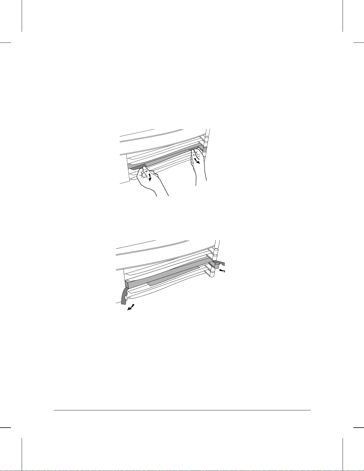
5. Press down slightly on the insides of both locks on the old card’s
bezel (see figure 2), then swing them outward until the bezel
disengages (see figure 3).
Figure 2. Unlocking Card Bezel
Figure 3. Disengaging Card Bezel
6. Grasping the left and right edges of the bezel, pull out until the tray is
about half exposed.
7. Grasping the sides of the tray, remove the card from the router.
8. Holding the new interface card by the sides of its tray, s lide the back
of the tray about half-way into the router.
6
Page 7

Installation
Install interface card.
9. Pull the locks on the bezel outward, then push evenly on both ends
until the card engages fully and the locks swing inward to about 45°.
Figure 4. Installing Interface Card
10. Push the two locks evenly to close them, pressing downward slightly
to secure them in place.
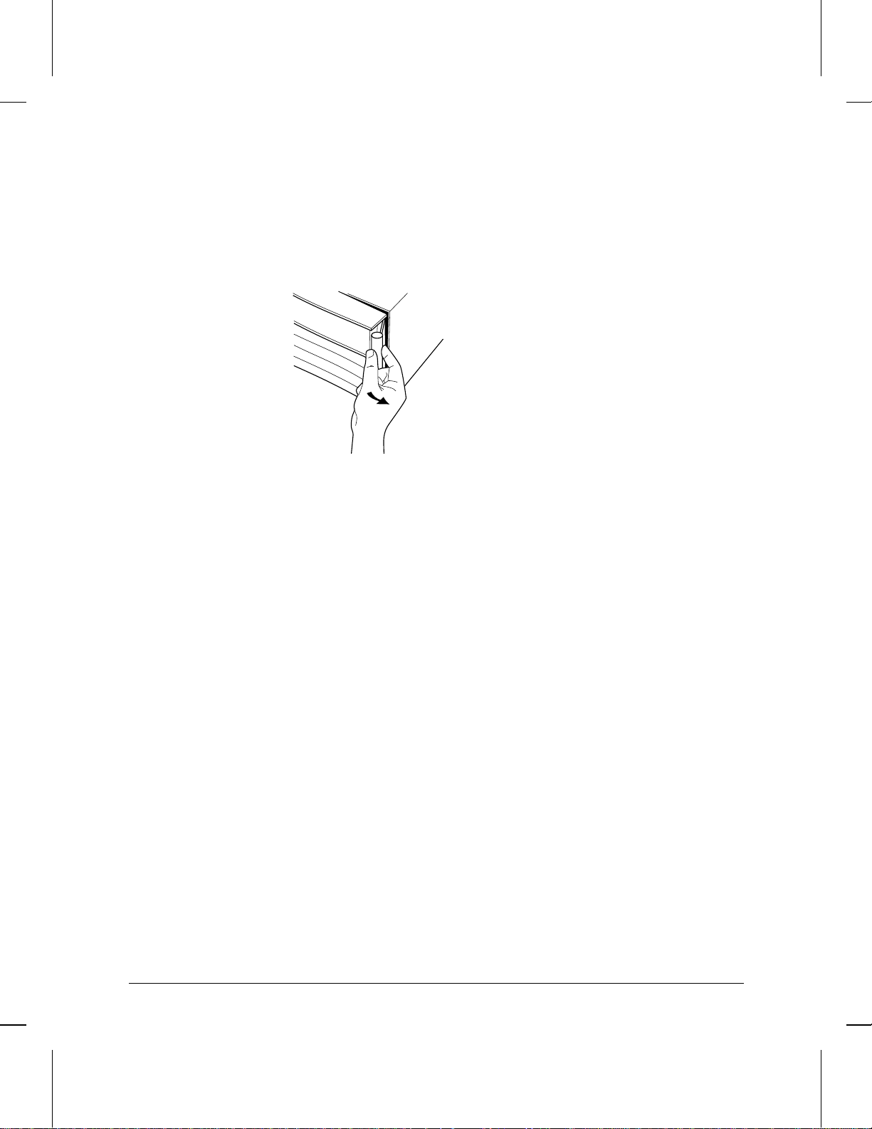
11. Remove the old card’s LED label s trip in the router door from the
position corresponding to the slot where you have installed the
interface card, then insert the LED label strip provided with the new
card as far as it will go.
12. Bend the end of the label strip toward the back of the router,
creating a 90° fold.
13. Switch on the power supply by pressing the top of the switch
(marked with “
| ”).
14. Close the router door.
7
Page 8

12
Fail
Rx Tx
Self testCard
Installation
Install interface card.
15. To replace the label at the left of the slot that identifies the department or site served by the interface card, slide it out from the right.
Position the new label with its shiny side facing the router, and slide
it in from the right. (Additional labels are provided in the router’s
accessories kit and also with each interface card.)
Self-test
Card
Reset Clear
1
Swap
HP J2608A
Swap
1
Swap
1
Rx
12
ThinLAN
4T
Swap
1
Figure 5. Interface Card Label Location
Net
Ins
Fail
2
HP J2608A
2
Remove and insert label
from this edge
2
8
Page 9

Installation
Install interface card.
Installing the Interface Card (System Online)
Note If you will be installing the new interface card in a slot where another
interface card is not currently installed, skip steps 1 and 3.
1. Disconnect all cables from the interface card you will be removing,
and save them for reconnection when you later install that card again.
2. Connect a grounding wrist strap (one is provided with the interface
card) to your wrist and to the back of the router.
3. If the Swap LED on the interface card you will be removing is not on
(see figure 6), press the adjacent Swap button, and hold it until the
Swap LED turns on (about 1–5 seconds).
1
Swap
J2434A
HP J2608A
4S
Figure 6. Swap Button and LED
ThinLAN
9
Page 10

Installation
Install interface card.
4. Press down slightly on the insides of both locks on the old card’s
bezel (see figure 7), then swing them outward until the bezel
disengages (see figure 8).
Figure 7. Unlocking Card Bezel
10
Figure 8. Disengaging Card Bezel
5. Grasping the left and right ends of the bezel, pull out until the tray is
about half exposed.
6. Grasping the sides of the tray, remove the card from the router.
7. Holding the new interface card by the sides of its tray, s lide the back
of the tray about half-way into the router.
Page 11

Installation
Install interface card.
8. Pull the locks on the bezel outward, then push evenly on both ends
until the card fully engages and the locks swing inward to about 45°.
Figure 9. Installing Interface Card
9. Push the two locks evenly to close them, pressing downward slightly
to secure them in place. A self-test of the new interface card begins.
10. When the self-test is complete (after about 5 seconds), check that the
new interface card’s Card LED (the first LED in the row of LEDs in
the router door) has turned green, and the Self-test LED (the second
LED in the row) has turned off.
• If these LEDs continue flashing, the card is not seated properly.
Adjust the position of the card by pushing evenly on both ends,
and adjust the positions of the locks evenly.
• If the Card LED remains orange and the Self-test LED remains on,
the card has failed the self-test. Refer to “Interface Card Self-Test
Failure During Hot Swap” in table 3-2, “LED Error Patterns
During Router Operation.”
• If the Card LED remains orange but the Self-test LED has turned
off, look in the event log (which can be displayed from the Main
menu) for the entry “Slot x HWID and Line configuration
mismatch” (where x is the number of the slot). If that entry
appears in the event log, specify the new card for that slot in the
configuration (refer to “Configure and boot the router” in chapter
1 of the HP Router 650 Installation Guide). If that entry does not
appear in the event log, call for service from your HP dealer or
service provider.
11
Page 12

Installation
Install interface card.
11. Open the front door of the router by pulling its lock—the round post
at the upper right—to the right.
Figure 10. Opening Router Door
12. Remove the old card’s LED label s trip from the position corresponding to the slot where you have installed the new interface card, then
insert the LED label strip provided with the new card as far as it will
go.
12
13. Bend the end of the label strip toward the back of the router,
creating a 90° fold.
14. Close the router door.
Page 13

12
Fail
Rx Tx
Self testCard
Installation
Install interface card.
15. To replace the label at the left of the slot that identifies the department or site served by the interface card, slide it out from the right.
Position the new label with its shiny side facing the router, and slide
it in from the right. (Additional labels are provided with the interface
card, as well as in the router’s accessories kit.)
Self-test
Card
Reset Clear
1
Swap
HP J2608A
Swap
1
Swap
1
Rx
12
ThinLAN
4T
Swap
1
Figure 11. Interface Card Label Location
Net
Ins
Fail
2
HP J2608A
2
Remove and insert label
from this edge
2
13
Page 14

Installation
Connect network cables.
Connect network cables.
Connect the network cables as described below. You should also make
sure that all network equipment and links are ready.
Caution Static discharge may damage equipment. Do not touch the connector
pins on the interface card or on the cable.
1. Secure the D-connector on the token ring cable to the token ring
port, using the screws on the connector.
Swap
123 4
Factory
Test
Trunk Coupling Unit (TCU)
Token ring cable
Figure 12. Connecting Token Ring Cable
2. Connect the medium interface connector (MIC; see figure 14, page
18) on the token ring cable to the token ring Trunk Coupling Unit
(TCU).
14
Page 15

Installation
Arrange network cables.
Arrange network cables.
To help keep the network cables orderly—and out of the w ay wh en
interface cards are being removed or installed—arrange the cables over
the bars at the right of the router.
These cable-management bars have slots in them that you can use for
tie-wrapping the network cables. Included with each interface card is a
tie-wrap that you can use to wrap the cables and then attach the bundle
to the cable management bar, as shown in figure 13.
Figure 13. Cable-Management Bar and Tie-Wrap
Some cables (such as WAN cables) will not fit inside the cable management bars. You can use the tie-wraps to bundle the extra cables and
hang them on the outside of the bar.
15
Page 16

Prepare the router.
Prepare the router.
To prepare the router after installing the new interface card, you should
do the following procedures, all of which are described in chapter 1 of
the HP Router 650 Installation Guide:
Connect a console.
Plug in and verify router hardware.
Configure and boot the ro uter.
Verify router initialization and configuration.
Note If you are installing the interface card in place of a different type of
interface card (for example, if the slot in which you are installing the
interface card formerly held a WAN interface card), or if you are
installing the interface card in a slot that formerly was empty, you must
specify the new card in the configuration.
If any port has no network attached during router operation, event log
messages are generated. To avoid these messages, disable that port
when you configure the router.
16
Page 17

Cables and Connectors
Troubleshooting
For general information about troubleshooting problems using any
interface card in the Router 650, refer to chapter 3 of the HP Router 650
Installation Guide. The following troubleshooting information is
specific to the token ring interface card.
Note In the description of the port status LEDs in chapter 2 of the HP Router
650 Installation Guide, the label “Tx” is shown for the third port status
LED for each port. On the LED label strip used with the token ring interface card, however, the third port status LED for each port is labeled
“Ins” instead (“Tx” is used for most other interface cards). The Ins LED
is lit green when the corresponding port on the interface card is passing
the token.
If the Net Fail LED for any (but not all) of the ports on the interface
card is lit during router operation, this may mean one of the following:
The network cable is loose, disconnected, or faulty.
The TCU is faulty.
The ring speed is configured incorrectly.
Cables and Connectors
Cable/Connector Source
Token ring, shielded, twisted-pair cable connecting
to the 9-pin female token ring port with a male 9-pin
subminiature D-connector
Loopback connector (RJ-45 modular to subminiature D-Connector)
Available from several
vendors, such as Black Box
and Inmac; not available from
HP.
HP part number 5061-2550
17
Page 18

Cables and Connectors
Token Ring Port Definition
Token Ring Port Definition
This port accepts the standard 9-pin male subminiature D-connector for
shielded twisted-pair token-ring cable.
Pin Definition of Token
Ring Connector
9-Pin
Connector
1 Data In B
2n/c
3n/c
4n/c
5 Data Out A
6 Data In A
7n/c
Token Ring
Signal
8n/c
9 Data Out B
The opposite end of the token-ring cable should be fitted with a medium
interface connector (MIC) conforming to the IEEE 802.5 specification.
Figure 14. Token Ring (802.5 MIC) Connector
18
Page 19

Cables and Connectors
Loopback Connector
Loopback Connector
Modular (RJ-45) to subminiature D-connector:
• pin 3 to pin 1
• pin 4 to pin 6
• pin 5 to pin 9
• pin 6 to pin 5
Subminiature D-Connector
• pin 1 to pin 9
• pin 5 to pin 6
Note This loopback connector is not a modular-to-9-pin adapter; the modular
and 9-pin connectors should not both be used at the same time.
19
Page 20

Part number: 5962-8322
E0894
Printed in U.S.A.
 Loading...