

Page 1

HP 24-Port 4x Fabric Copper Switch
User Guide
November 2004 (First Edition)
Part Number 377710-001
Page 2

© Copyright 2004 Hewlett-Packard Development Company, L.P.
Confidential computer software. Valid license from HP required for possession, use or copying. Consistent with
FAR 12.211 and 12.212, Commercial Computer Software, Computer Software Documentation, and Technical
Data for Commercial Items are licensed to the U.S. Government under vendor’s standard commercial license.
The information contained herein is subject to change without notice. The only warranties for HP products and
services are set forth in the express warranty statements accompanying such products and services. Nothing
herein should be construed as constituting an additional warranty. HP shall not be liable for technical or editorial
errors or omissions contained herein.
Microsoft®, MS Windows®, Windows®, and Windows NT® are U.S. registered marks of Microsoft Corporation.
HP 24-Port 4x Fabric Copper Switch User Guide
November 2004 (First Edition)
Part Number 377710-001
Page 3

Contents
Intended Audience ..................................................................................................................................... ix
Typographical Conventions....................................................................................................................... ix
Contact Information.....................................................................................................................................x
1: Introducing the InfiniBand System ............................. 1
About the HP 24-Port 4x Fabric Copper Switch User Guide ......................................................................1
Maximize Server Networks .........................................................................................................................1
What is InfiniBand? .....................................................................................................................................2
How Does InfiniBand Work? ......................................................................................................................2
Possible Components...................................................................................................................... 2
Protocols ......................................................................................................................................... 2
Architectural Elements ................................................................................................................... 3
Understanding the Subnet Manager (SM) ...................................................................................... 4
Understanding Subnet Manager Routing........................................................................................ 5
i
2: Getting Started........................................................... 9
Overview of Set-up Procedures ...................................................................................................................9
Install HCAs and Drivers in Hosts ............................................................................................................10
Install and Power on the InfiniBand Chassis .............................................................................................10
Configure Basic Connectivity....................................................................................................................10
Configuring an Ethernet Management IP Address ....................................................................... 10
Configuring a Direct Serial-Console Connection ......................................................................... 11
Configuring an InfiniBand Management IP Address ................................................................... 12
Configuring the System Hostname ............................................................................................... 12
Test Network Connectivity........................................................................................................................13
Verify Communication Between Hosts ........................................................................................ 13
Verify Switch to Host Communication ........................................................................................ 14
Install the GUI (Element Manager) ...........................................................................................................14
Access a Management System...................................................................................................................14
Default User Name and Passwords............................................................................................... 14
CLI Management .......................................................................................................................... 14
GUI Management ......................................................................................................................... 15
SNMP Management...................................................................................................................... 15
(Optional) Enable Database Sync ..............................................................................................................15
Configure Partitions...................................................................................................................................15
Create a Partition ID (P_Key)....................................................................................................... 16
Specify Partition Members and the
Membership Type ......................................................................................................................... 17
Maintain Partition Key Information ............................................................................................. 17
Set User Levels and Passwords..................................................................................................................18
Page 4

ii
Change Default User Name and Password ................................................................................... 18
3: Understanding the Management Options ................ 19
About the CLI ............................................................................................................................................19
Understanding the Command Modes ........................................................................................... 20
Using the CLI.............................................................................................................................................21
Entering the Sub-Command Mode ............................................................................................... 21
Exiting Command Modes ............................................................................................................. 21
Using Command Completion ....................................................................................................... 21
Displaying Command History ...................................................................................................... 22
Setting Terminal Parameters......................................................................................................... 22
Ending A CLI Session .................................................................................................................. 23
Quick Help.................................................................................................................................... 24
About Element Manager............................................................................................................................24
The Chassis Window .................................................................................................................... 25
The Tool Bar................................................................................................................................. 25
About Selecting Items................................................................................................................... 26
Using Element Manager ............................................................................................................................27
Installing the Element Manager Program ..................................................................................... 27
Starting the Element Manager ...................................................................................................... 29
Reading the Element Manager Status Colors ............................................................................... 30
About SNMP..............................................................................................................................................30
Supported MIBs............................................................................................................................ 30
Using SNMP ..............................................................................................................................................30
Configuring SNMP Settings ......................................................................................................... 30
4: Performing Admin Tasks Through the GUI.............. 33
Configuring the IB Interface Speed ...........................................................................................................33
Explicitly Configure IB Interface Speed ...................................................................................... 33
Set IB Interface Speed to Auto-Negotiate .................................................................................... 34
View the IB Interface Speed......................................................................................................... 35
Setting the System Clock...........................................................................................................................36
Setting Time Manually ................................................................................................................. 36
Synchronize the Clock to an NTP Server ..................................................................................... 36
Rebooting the System ................................................................................................................................37
Reboot a System with a Single Controller Card ........................................................................... 37
5: Performing Admin Tasks Through the CLI............... 39
Setting the IB Interface Speed ...................................................................................................................39
Explicitly Configure IB Interface Speed ...................................................................................... 39
Set IB Interface Speed to Auto-Negotiate .................................................................................... 40
View the IB Interface Speed......................................................................................................... 40
Notifying Users..........................................................................................................................................40
Broadcasting Messages to all Users.............................................................................................. 41
Sending Messages to Individual Users ......................................................................................... 41
Page 5

Setting the System Clock...........................................................................................................................41
Setting Time.................................................................................................................................. 42
Synchronize the Clock to an NTP Server ..................................................................................... 42
Rebooting the System ................................................................................................................................43
Reboot a System with a Single Controller.................................................................................... 43
6: Setting Access and Security .................................... 45
Understanding Access and Accounts.........................................................................................................45
About User Accounts.................................................................................................................... 45
Elements of the Access System .................................................................................................... 46
Understanding Usernames and Passwords .................................................................................. 46
About Roles and Privileges........................................................................................................... 46
Managing Access and Accounts ................................................................................................................47
Setting or Changing a Password ................................................................................................... 47
Displaying User Information ........................................................................................................ 48
Adding New Users........................................................................................................................ 49
Deleting a User Account............................................................................................................... 50
User Account Configuration Commands...................................................................................... 50
Switching User Identity ................................................................................................................ 52
Changing Privilege Access-Levels ............................................................................................... 52
About Partitions .........................................................................................................................................53
How Partitions Work .................................................................................................................... 53
Partition Members......................................................................................................................... 54
Membership Types ....................................................................................................................... 54
Selecting a P_Key Value .............................................................................................................. 54
Understanding how P_Keys are Saved......................................................................................... 56
Create Partitions (CLI)...............................................................................................................................56
Create a Partition ID (P_Key)....................................................................................................... 57
Specify Partition Members and the
Membership Type ......................................................................................................................... 57
Create Partitions (GUI)..............................................................................................................................57
Create a Partition ID (P_Key)....................................................................................................... 57
Specify Partition Members and the
Membership Type ......................................................................................................................... 58
About SSH .................................................................................................................................................59
iii
7: Using the Subnet Manager Through the GUI .......... 61
The Subnet Manager (SM).........................................................................................................................61
Master Subnet Manager ................................................................................................................ 61
Standby Subnet Manager .............................................................................................................. 62
Viewing the Subnet Manager Configurations............................................................................................62
View a Summary of Subnet Management .................................................................................... 62
View Details of Subnet Management ........................................................................................... 62
Changing the Subnet Manager Configurations..........................................................................................64
Change the Priority of a SM ......................................................................................................... 64
Change the Sweep Interval of a SM ............................................................................................. 64
Page 6

iv
Change the Response Timeout of a SM........................................................................................ 65
Managing Synchronization Between SMs.................................................................................................66
Enable/Disable Database Synchronization ................................................................................... 66
Set Configurations for the Master SM.......................................................................................... 67
Set Configurations for the Backup SM......................................................................................... 68
Adding a Subnet Manager .........................................................................................................................70
Viewing Partitions .....................................................................................................................................71
About InfiniBand Multicast Groups ..........................................................................................................72
Viewing Multicast Groups.........................................................................................................................72
View a Multicast Group Summary ............................................................................................... 72
View Multicast Group Details ...................................................................................................... 73
View the Subnet Manager Services ...........................................................................................................75
View a Summary of the SM Services........................................................................................... 75
View Details of the SM Services.................................................................................................. 76
Configure Subnet Manager Routing ..........................................................................................................77
Configure the LID Mask Control (LMC) ..................................................................................... 78
View InfiniBand Paths.................................................................................................................. 78
8: Using the Subnet Manager Through the CLI ........... 81
The Subnet Manager (SM).........................................................................................................................81
Master Subnet Manager ................................................................................................................ 81
Standby Subnet Manager .............................................................................................................. 82
Viewing the Subnet Manager Configurations............................................................................................82
View a Summary of Subnet Management .................................................................................... 82
View Details of Subnet Management ........................................................................................... 82
Changing the Subnet Manager Configurations..........................................................................................83
Change the Priority of a SM ......................................................................................................... 83
Change the Sweep Interval of a SM ............................................................................................. 84
Change the Response Timeout of a SM........................................................................................ 84
Managing Synchronization Between SMs.................................................................................................84
Enable/Disable Database Synchronization ................................................................................... 84
Set Configurations for the Master SM.......................................................................................... 85
Set Configurations for the Backup SM......................................................................................... 85
Adding a Subnet Manager .........................................................................................................................87
About InfiniBand Multicast Groups ..........................................................................................................87
Viewing Multicast Groups.........................................................................................................................88
View a Multicast Group Summary ............................................................................................... 88
View Multicast Group Details ...................................................................................................... 89
Viewing the SM Services ..........................................................................................................................90
View a Summary of the SM Services........................................................................................... 90
Configure Subnet Manager Routing ..........................................................................................................90
Configure the LID Mask Control (LMC) ..................................................................................... 91
View InfiniBand Paths.................................................................................................................. 91
9: Using Image Files .................................................... 93
Types of Image Upgrades ..........................................................................................................................93
Page 7

TopspinOS Upgrades.................................................................................................................... 93
About the System Image............................................................................................................................93
What is a System Image?.............................................................................................................. 93
What is an Image File? ................................................................................................................. 94
About Copying/Downloading the Image...................................................................................................94
Card Status Requirements..........................................................................................................................95
Upgrade Procedure Overview....................................................................................................................95
Set-Up the Hardware Connection ..............................................................................................................95
Out-of-Band Connection............................................................................................................... 95
In-Band Connection...................................................................................................................... 95
Verify the Installed Image Version............................................................................................................96
Check the Image Version Through the GUI................................................................................. 96
Check the Image Version Through the CLI.................................................................................. 96
Copy/Download the Image ........................................................................................................................96
Copy/Download the Image Through the GUI .............................................................................. 97
Copy/Download an Image Through the CLI ................................................................................ 98
Activate an Image ....................................................................................................................................100
Specify a New Boot Image ......................................................................................................................101
Specify a New Boot Image Through the GUI ............................................................................ 101
Specify a New Boot Image Through the CLI ............................................................................. 102
Reboot the System ...................................................................................................................................102
Deleting Image Files................................................................................................................................103
Deleting Images Through the GUI ............................................................................................. 103
Deleting Images Through the CLI .............................................................................................. 103
v
10: Using Configuration Files..................................... 105
Understanding Configuration Files..........................................................................................................105
About the Startup-Config............................................................................................................ 105
About the Running-Config ......................................................................................................... 105
Listing Configuration Files......................................................................................................................106
List Config Files Through the CLI ............................................................................................. 106
List Config Files Through the GUI............................................................................................. 106
Export a Configuration File .....................................................................................................................106
Export a Config File Through the CLI ....................................................................................... 107
Export a Config File Through the GUI....................................................................................... 107
Import a Configuration File .....................................................................................................................108
Download a Config File Through the CLI.................................................................................. 108
11: Using Log Files .................................................... 111
Understanding Log Files..........................................................................................................................111
File Management and Storage .................................................................................................... 111
About Message Types................................................................................................................. 111
Listing Current Log File Names ..............................................................................................................112
Listing Current Logs Through the CLI....................................................................................... 112
Listing Current Logs Through the GUI ...................................................................................... 112
Viewing a Log File Through the CLI ......................................................................................................113
Page 8

vi
Display Entire Log...................................................................................................................... 113
Show Most Recent Log Entries .................................................................................................. 113
Show Details of a Specific Log .................................................................................................. 114
Viewing a Log File Through the GUI......................................................................................................114
Filtering Logs.............................................................................................................................. 115
Configuring Remote Logging..................................................................................................................117
12: Viewing the IB Network Through the GUI ............ 119
About the Device Manager (DM)............................................................................................................119
Display the Device Manager....................................................................................................................119
View I/O Unit Information ......................................................................................................... 119
View I/O Controller Units .......................................................................................................... 120
View I/O Controller Units Services............................................................................................ 121
About the Topology View .......................................................................................................................121
Display the InfiniBand Topology ............................................................................................................122
View the Topology ..................................................................................................................... 122
View the Name of an HCA......................................................................................................... 123
View the GUID of an HCA ........................................................................................................ 124
Determine Which HCA Port is Connected to an IB Port ........................................................... 124
View the GUID of an IB Switch................................................................................................. 126
Add an Attached Device to the Topology View......................................................................... 126
View the Internal Chassis Topology........................................................................................................127
View Subnet Manager Details .................................................................................................................129
View Basic Node Information .................................................................................................... 129
View Advanced Node Information............................................................................................. 130
View Basic Port Information ...................................................................................................... 131
View Advanced Port Information............................................................................................... 133
13: Monitoring and Reporting Through the GUI......... 137
About Analyzing Network Data ..............................................................................................................137
Benefits ....................................................................................................................................... 137
Data Captured ............................................................................................................................. 138
About Tabular Formats ............................................................................................................................138
About Graph Formats ..............................................................................................................................138
Types of Graphs.......................................................................................................................... 138
Creating a Data Analysis Table ...............................................................................................................140
Create a Data Table..................................................................................................................... 140
Export a Data Table .................................................................................................................... 141
Print a Data Table ....................................................................................................................... 142
Creating a Data Analysis Graph ..............................................................................................................143
Modify a Graph........................................................................................................................... 145
Print a Graph............................................................................................................................... 146
About SNMP Traps .................................................................................................................................146
Events Sent to Trap Receivers .................................................................................................... 146
Configuring SNMP Settings ....................................................................................................................147
Viewing Current SNMP Trap Receivers .................................................................................... 147
Page 9

Adding an SNMP Trap Receivers .............................................................................................. 147
Editing a Current SNMP Trap Receiver ..................................................................................... 148
14: Monitoring Through the CLI ................................. 149
About InfiniBand Events .........................................................................................................................149
About Tracing ..........................................................................................................................................149
Types of Traces........................................................................................................................... 150
Trace Levels................................................................................................................................ 150
About SNMP Traps .................................................................................................................................151
Events Sent to Trap Receivers .................................................................................................... 151
Configuring SNMP Settings ....................................................................................................................152
Viewing Current SNMP Trap Receivers .................................................................................... 152
Add an SNMP Trap Receiver ..................................................................................................... 152
vii
Page 10

viii
Page 11

Preface
ix
This document is a guide to the HP 24-Port 4x Fabric Copper Switch.
Intended Audience
The intended audience is the administrator responsible for installing, configuring, and managing your
equipment. This administrator should have experience administering similar networking or storage
equipment.
Typographical Conventions
The following typographic conventions are used in this manual to provide visual clues as to the purpose
or application of specific text.
• Bold text indicates a command.
• Courier text indicates example text as displayed on the computer screen or that you enter exactly as
shown.
• Italics indicate variable text that you replace with an actual value.
• Square angle-brackets ([data]) indicate an option that you choose to include or exclude. (Do not
include the brackets when supplying optional data.)
• Piping character (|) indicates an “or” choice. For example, a | b indicates “a or b”. [a] | [b] indicates
an optional choice between a or b.
• Menu1->Menu2->Item… indicates a pop-up menu sequence to open a form or execute a desired
function.
• Ellipses (…) indicate truncated text. You will see these in long examples depicting terminal output
that is too long to be shown in its entirety.
Page 12

x
NOTE: Indicates an important point or aspect that you need to consider before continuing.
Contact Information
Table 2-1: Customer Contact Information
For the name of your nearest authorized
HP reseller:
For HP technical support: In the United States and Canada, call 1-800-HP-INVENT
In the United States, call 1-800-345-1518.
In Canada, call 1-800-263-5868.
(1-800-474-6836). This service is available 24 hours a day,
7 days a week. For continuous quality improvement, calls
may be recorded or monitored.
Outside the United States and Canada, refer to
www.hp.com
Page 13

Introducing the InfiniBand System
This chapter gives an overview of the following:
• “About the HP 24-Port 4x Fabric Copper Switch User Guide” on page 1
• “Maximize Server Networks” on page 1
• “What is InfiniBand?” on page 2
• “How Does InfiniBand Work?” on page 2
1
1
About the HP 24-Port 4x Fabric Copper Switch User Guide
The HP 24-Port 4x Fabric Copper Switch User Guide is specifically intended to demonstrate the
processes involved in using and managing the InfiniBand
• For information regarding the Host Channel Adapter, refer to the HP Dual-port 4x Fabric Adapter
User Guide.
• For information regarding the switch, refer to the HP 24-Port 4x Fabric Copper Switch Hardware
User Guide.
™ switch technology.
Maximize Server Networks
The Topspin system uses InfiniBand as the underlying fabric that creates a scalable and efficient server
area network. The system also seamlessly interconnects with existing Fibre Channel and Ethernet
resources, extending the value of InfiniBand to the rest of the network.
Page 14

2
What is InfiniBand?
InfiniBand (IB) is a high speed, high density serial interconnect that increases CPU utilization,
decreases latency, and eases the management pain of data centers.
The term “InfiniBand” refers to the entire hardware, communication, and management infrastructure.
Use of this technology increases the communication speed between:
•CPUs
• devices within servers
• subsystems located throughout a network.
How Does InfiniBand Work?
InfiniBand combines high-speed hardware, specialized protocols, and Remote Data Memory Access
(RDMA) techniques to achieve the objective of increased CPU utilization and decreased latency.
Operations of the InfiniBand Architecture are managed by the Subnet Manager.
Possible Components
One or more of the following hardware components may be used to maximize your server network.
• InfiniBand switch
• Host Channel Adapters (installed in host)
• Ethernet Gateway
• Fibre Channel Gateway
Protocols
InfiniBand requires a new set of protocols. For information on how to configure these protocols, refer to
the HP Dual-port 4x Fabric Adapter User Guide.
IPoIB
The IP over IB (IPoIB) link driver provides standardized Internet Protocol encapsulation over
InfiniBand fabrics. IPoIB can transparently use IP over InfiniBand technology, similar to the way that
IP runs over Ethernet.
The primary responsibilities of the IPoIB driver are to perform address resolution and the management
of multicast membership.
SDP
The Sockets Direct Protocol (SDP) is a transparent protocol used on InfiniBand networks to allow
sockets-based applications to take advantage of the RDMA performance over an InfiniBand network.
SDP provides:
• a reduction in the amount of software running inside a process context
• zero copy
SDP protocol support enables databases, application servers, and CPUs to operate more efficiently
because the databases spends less time waiting for work, the application servers spend less time waiting
for responses, and the CPUs have more cycles free for other work.
SRP
SCSI RDMA Protocol (SRP) is an upper-layer storage protocol for InfiniBand. It runs SCSI commands
across RDMA-capable networks for InfiniBand hosts to communicate with Fibre Channel storage
Page 15

devices. This protocol allows InfiniBand hosts to natively send SCSI commands as if the storage was
direct attached.
The SRP protocol is designed to operate using an RDMA communication service. An RDMA
communication service provides communication between pairs of consumers; it uses messages for
control information and RDMA operations for data transfers.
The SRP protocol is only used if you have a Fibre Channel Gateway installed in your InfiniBand
system.
uDAPL
The user Direct Access Programming Library (uDAPL) is a standardized user mode API that natively
supports InfiniBand fabrics.
uDAPL performs name to address translations, establishes connections, and transfers data reliably.
The primary responsibilities of uDAPL are:
• Connection management
• Low latency data transfer and completion
MPI
The MPI protocol is bundled with the Upper Layer Protocol (ULP) suite. Topspin has taken the Ohio
State University’s (OSU’s) MVAPICH and created Topspin’s version of this release. However, in
addition, the HCAs also run using other popular InfiniBand MPI implementations.
Alternative MPI Implementations
Topspin customers have also deployed a variety of MPIs that use Mellanox’s VAPI layer. This includes
OSU, LAM-MPI, Verari Systems Software, Inc’s MPI/Pro (formerly Softech’s ), and LANL MPI.
Topspin products have also been used successfully with SCALI MPI, which is based on uDAPL.
Differences Between Topspin and Standard MPI
There are significant differences between the version of MPI provided, and OSU’s MPI.
• There is no restriction on which HCA port is used (OSU only supports Port 1)
• Support for Opteron 64 bit operation is provided
• Bug fixes have been provided for the purpose of improving stability
3
Architectural Elements
What is RDMA?
InfiniBand utilizes Remote Direct Memory Access (RDMA) technology. RDMA is a technology that
allows one computer to place information directly into the memory of another computer.
RDMA is specifically characterized by two important features:
• allows user space applications to directly access hardware
• zero-copy data movement
A combination of hardware and software allows user space applications to read and write the memory
of a remote system without kernel intervention or unnecessary data copies. This results in lower CPU
utilization per I/O operation and more efficient use of machine resources because applications place
most of the messaging burden upon InfiniBand’s high-speed network hardware.
Work Queues and Queue Pairs
A “verb” is the abstract description that is used to define the functionality of the Host Channel Adapter
(HCA). A “verb consumer” refers to the direct user of the verb.
A work queue provides a verb consumer with the ability to queue up a set of instructions that are
executed by the Channel Adapter. There are two types of Work Queues: Send Work Queue (outbound)
and a Receive Work Queue (inbound). Together these Work Queues create a Queue Pair.
Page 16

4
The Queue Pair (QP) is one of the primary architectural elements of InfiniBand. In InfiniBand,
communication occurs between Queue Pairs, instead of between ports.
A Queue Pair (QP) in an addressable entity, and consists of two Work Queues: 1). Send Work Queue
and a 2). Receive Work Queue. (A work queue provides a verb consumer with the ability to queue up a
set of instructions that are executed by the Channel Adapter.) The Channel Adapter hardware takes over
the task of arbitrating communication - multiplexing access to the send queue or de-multiplexing
messages on the receive queue.
A connection is made by linking a local queue pair to a remote queue pair. Applications do not share
queue pairs; therefore, once you set them up, you can manage them at the application level without
incurring the overhead of system calls.
Send and Receive work queues are:
• always created as a pair
• always remain a pair
• known as Queue Pairs
• identified by a Queue Pair number, which is within the Channel Adapter.
Queue pairs have:
• a region of memory to be used as buffers (numbers of Queue Pairs are only limited by memory).
• a key that must match on each incoming packet (the Q_Key) to verify the validity of the packet
• (potentially) a partition key, which specifies the portion of the fabric that this queue pair may
access.
The queue pair is the mechanism by which you define quality of service, system protection, error
detection and response, and allowable services.
Types of Services
Each queue pair is independently configured for a particular type of service. These service types
provide different levels of service and different error-recovery characteristics.
The available transport-service types include:
• Reliable connection
• Unreliable connection
• Reliable Datagram
• Unreliable Datagram
Once the fabric connections are discovered, queue pairs and protection domains are established, and the
type and quality of service are defined for each queue pair, the fabric operates reliably and securely at
full performance without impact on system hardware or software resources.
Understanding the Subnet Manager (SM)
The Subnet Manager configures and maintains fabric operations. There can be multiple Subnet
Managers, but only one master.
For information regarding configuring the subnet managers, refer to “Using the Subnet Manager
Through the GUI” on page 61 or “Using the Subnet Manager Through the CLI” on page 81.
The Subnet Manager is the central repository of all information that is required to setup and bring up the
InfiniBand fabric.
The master Subnet Manager
• Discovers the fabric topology.
• Discovers endnodes.
• Configures switches and end nodes with their parameters, such as:
Page 17

• Local Identifiers (LIDs)
• Global Unique Identifier (GUIDs)
• Partition Key (P_Keys)
• Configures switch forwarding tables.
• Receives traps from Subnet Management Agents (SMAs).
• Sweeps the subnet, discovering topology changes and managing changes as nodes are added and
deleted.
Understanding the Subnet Management Agents (SMAs)
Subnet Management Agents (SMA) are part of the Subnet Manager. A SMA is provided with each node
and process packets from the Subnet Manager.
If an Subnet Manager is elected master, all of its components, including SA, are implicitly elected
master. If a Subnet Manager ceases to be master, all of its components cease responding to messages
from clients.
Subnet Manager Hot Standby
The master and slave subnet managers can be synchronized so the information in the master is carried
over to the slave in the event of a fail-over. Refer to “Enable/Disable Database Synchronization” on
page 84 to configure SM hot standby.
The hot standby/database sync feature is used to synchronize the databases between subnet managers
running on separate chassis.
The Subnet Manager maintains a data base in the volatile memory of the master SM containing all
required information.
How is the synchronization done?
The database synchronization is accomplished in two stages:
• Cold Synchronization - This stage is initiated by the master SM when it is ready to start a
synchronization session with a standby SM. In this stage, all out of sync tables are copied from the
master SM to the standby SM.
• Transactional Synchronization - This stage is entered following successful completion of the cold
synchronization stage. In this stage, all database update transaction requests that are processed by
the master, are replicated to the standby.
What can cause a standby SM to become the master SM?
• A crash of the node running the current master SM.
• Partitioning of the subnet (e.g. due to link failure).
• Graceful shutdown of the master (e.g. for maintenance purposes).
What happens when a master subnet manager fails?
In the event of a failure:
• The standby subnet manager becomes the new master.
• The new master rebuilds the data base from information retrieved during the subnet discovery
phase.
• Existing LID assignments are retained, where possible.
• All ports are reset to force them to re-join multicast groups, re-advertise services, re-request event
forwarding, and re-establish connections.
• A “SlaveToMaster” event trap is generated to trigger any necessary processing by external
management applications.
5
Understanding Subnet Manager Routing
There are two different concepts associated with InfiniBand routing:
Page 18

6
• Routing internally within a switch (hops between switch chips)
• Routing between whole switches (hops between nodes). This is also referred to as routing between
“switch elements.”
Internal switch routing can be configured to provide the highest performance in passing traffic, and to
minimize the threat of congestion within the switch.
The Routing Process Overview
1. The Subnet Manager (SM) first discovers all the InfiniBand switch chips in the network.
2. The SM groups the internal switch chips within each chassis into a “switch element.”
3. The SM process continues until all the InfiniBand switches are grouped into “switch elements.”
4. After all the switch chips are grouped, the SM will route the switch elements according to the
routing algorithm discussed in “Minimum Contention, Shortest Path & Load Balancing Algorithm”
on page 6.
5. The internal network of each InfiniBand switch is then routed based on the best algorithm for each
“switch element.”
Multiple Paths
The SM allows you to define the Logical Identifier Mask Control (LMC) value per subnet. The default
value of the LMC is 0, so by default only one Logical Identifier (LID) is assigned to each host port.
Once the LMC value has been assigned, the SM will route different paths for each LID associated with
the same host port. The result of these paths is based on the routing algorithm applied.
Understanding SM Routing Terms
The following terms are important to understand before distinguishing the various types of algorithms
that the Subnet Manager uses for routing:
Distance - Distance is defined as the number of hops (InfiniBand switches or “switch elements”)
between source and destination.
Contention - A contention is declared for every switch port on the path that is already used for routing
another LID associated with the same host port.
Minimum Contention, Shortest Path & Load Balancing
Algorithm
Minimum Contention, Shortest Path and Load Balancing is the algorithm that is used by default to route
between the “switch elements” and for routing between the internal InfiniBand switch chips within each
“switch element.”
The following algorithm is used for the calculation:
1. The shortest path for each of the host ports is calculated.
2. Contention is calculated for all the available paths that are within the (shortest path + tolerance)
distance.
a. The path with the least contention is selected.
b. If two paths have the same contention, the path with less distance is selected.
c. If two paths have the same contention and the same distance, the port usage count is used to
provide load balancing over the two paths. The usage count is a measure of how many LIDs have
been configured to use that particular port.
Configuring Your Network For Optimal Routing
Create Equal Paths Between Switch Elements
It is recommended that InfiniBand switch elements be connected so that all paths between any pair of
switch elements are the same distance (i.e. same number of hops), if possible. This enables you to
obtain the optimal paths using the default tolerance of 0.
Page 19

Determine the First Path that will be Discovered
The SM Routing Algorithm selects the first best path that it finds. If multiple paths with the same
properties are available then the first of these paths found is the one that is selected. Therefore, it is
possible to setup the cabling between switch elements to force the algorithm to prioritize certain paths.
Depending on the network requirements, the prioritized paths can either be concentrated on a particular
switch element or spread across multiple switch elements to improve fault-tolerance.
7
Page 20

8
Page 21

Getting Started
The information in this chapter focuses on the software and firmware aspects of the initial set-up, and
assumes that you have additional documentation for the hardware.
This chapter provides the following information:
• Overview of entire system installation on page 9, with references to more detailed information.
9
2
• Setup procedures for the InfiniBand
™ switch.
Overview of Set-up Procedures
Follow the steps below to configure the InfiniBand server switch system.
1. Determine your hardware topology.
2. Install the Host Channel Adapter and drivers (page 10).
3. Install and power-on the InfiniBand Chassis (page 10).
4. Configure Basic Connectivity (page 10).
5. Test Network Connectivity (page 13).
6. Install the Element Manager GUI (page 14).
7. Access a Management System (page 14).
8. Configure Partitions (page 15).
9. Set User Level and Access (page 18).
Page 22

10
Install HCAs and Drivers in Hosts
Refer to the HP Dual-port 4x Fabric Adapter Quick Setup Installation card and the HP Dual-port 4x
Fabric Adapter User Guide.
Install and Power on the InfiniBand Chassis
Refer to the HP 24-Port 4x Fabric Copper Switch Hardware Quick Setup Installation card and the HP
24-Port 4x Fabric Copper Switch Hardware User Guide for installation and power instructions.
Configure Basic Connectivity
The InfiniBand switch is not pre-configured with an IP address. You must configure the IP address of a
management port to administer and monitor the InfiniBand switch with the CLI and Element Manager.
A Management port is provided for a connected Ethernet host running TCP/IP or connected InfiniBand
hosts running IPoIB. Configure the Management port you wish to use.
• “Configuring an Ethernet Management IP Address” on page 10
• “Configuring an InfiniBand Management IP Address” on page 12
Login: super
Password: super
Topspin-360>
Configuring an Ethernet Management IP Address
To configure an out-of-band Ethernet Management IP address:
1. Make sure that the InfiniBand switch is attached to a PC or terminal via the serial port. Refer to the
HP 24-Port 4x Fabric Copper Switch Hardware Quick Setup Installation card and the HP 24-Port
4x Fabric Copper Switch Hardware User Guide.
2. Open a terminal emulation program, such as HyperTerminal for Windows
parameters as follows:
• Baud: 9600 b/s
• Data Bits: 8
•Parity: None
• Stop Bits: 1
• Flow control: None
3. At the Login: prompt, enter the username and password. The default is super and super.
Example
®, and set the session
4. At the CLI prompt, enter enable. This enters the privileged-execute mode.
Topspin-360> enable
5. Enter configure to enter the global-configuration mode.
Topspin-360# configure
Topspin-360(config)#
Page 23

6. Set the IP address and netmask. The following address is an example.
Topspin-360(config)# interface mgmt-ethernet
Topspin-360(config mgmt-ethernet)# ip address 10.10.0.22 255.255.255.0
7. Set the default gateway address. This address is an example.
Topspin-360(config mgmt-ethernet)# gateway 10.10.0.1
8. Enable the management port
Topspin-360(config mgmt-ethernet)# no shutdown
9. Test IP connectivity by pinging the management station.
Topspin-360(config mgmt-ethernet)# exit all
Topspin-360> ping 10.10.0.3
sending 5 ICMP Echos to 10.10.0.3, 56 data bytes
!!!!!
Success rate is 100 percent (5/5)
round-trip min/avg/max = 0.000000/0.000000/0.000000 ms
Topspin-360>
copy
10. You must save the configuration persistently by using the
command.
11
Topspin-360(config mgmt-ethernet)# exit
Topspin-360# copy running-config startup-config
You are now ready to power down the chassis and mount it. Later, you can configure the box via
Telnet, SSH, Chassis Manager or Element Manager.
Configuring a Direct Serial-Console Connection
Refer to the HP Serial Management Cable Guide for information regarding setting up the physical
serial-console connection.
Remote Telnet Login
You can Telnet to the Management-Ethernet port on the box from a host on the same network as the
Management-Ethernet port, or from any host with a route to the Management-Ethernet network.
To run the CLI remotely:
1. Open a terminal or terminal emulator window.
For example: from the command line, enter the telnet command with the IP address, or network
name, of the Management-Ethernet port.
# telnet 10.0.0.47
The CLI login prompt (Login: ) is displayed.
2. Enter a CLI user name.
The CLI password prompt (Password:) is displayed.
3. Enter the CLI user password.
The prompt changes to indicate a successful login. The system is now ready to receive CLI
commands.
Remote SSH Login
TopspinOS supports SSH2 for secure, encrypted login to the CLI. SSH is enabled by default, and does
not require additional configuration.
Page 24

12
Login: super
Password: super
Topspin-360>
Topspin-360> enable
Topspin-360#
Topspin-360# configure
Topspin-360(config)#
To login via SSH:
1. Use an SSH client (e.g. Putty) to port 22.
Configuring an InfiniBand Management IP Address
To configure an In-band InfiniBand management IP address:
1. At the Login: prompt, enter the username and password. The default is super and super.
2. At the CLI prompt, enter enable. This enters the privileged-execute mode, as indicated by the #
sign.
3. Enter configure to enter the configuration mode.
4. Enter the interface to be configured, and set the IP and mask addresses.
Topspin-360(config)# interface mgmt-ib
Topspin-360(config mgmt-ib)# ip address 10.3.102.20 255.255.255.0
5. Set the default gateway address. The gateway address refers to the address of the internal port.
Topspin-360(config mgmt-ib)# gateway 10.3.0.1
6. Enable the IB management port.
Topspin-360(config mgmt-ib)# no shutdown
7. Test IP connectivity by pinging an InfiniBand host on the other side of the gateway.
Topspin-360(config mgmt-ib)# exit all
Topspin-360> ping 10.3.102.34
sending 5 ICMP Echos to 10.3.102.34, 56 data bytes
!!!!!
Success rate is 100 percent (5/5)
round-trip min/avg/max = 0.000000/0.000000/0.000000 ms
Topspin-360>
8. Save the configuration by using the copy command, or wait until you execute the reload command.
You will be prompted to save the unsaved configuration changes. .
Topspin-360(config mgmt-ethernet)# exit
Topspin-360# copy running-config startup-config
You are now ready to power down the chassis and mount it. Later, you can configure the box via
Telnet, SSH, or the Element Manager.
Configuring the System Hostname
The Topspin system allows you to assign a hostname to the system for management purposes.
Page 25

To assign a hostname name to the management port:
1. Start a CLI session.
2. Enter the privileged-user mode.
Topspin-360> enable
Topspin-360#
3. Enter the global-configuration mode.
Topspin-360# configure
Topspin-360(config)#
13
4. Enter the
The
prompt.
Topspin-360(config)# hostname MyHost
NOTE: This command also changes the CLI prompt. The new hostname is applied immediately,
however, the prompt does not change until you change modes. For example, the prompt changes
when you exit the global-configuration mode.
hostname
hostname
command with the name you wish to assign.
command assigns a convenient name to the system that shows up at the CLI
Test Network Connectivity
Refer to the HP 24-Port 4x Fabric Copper Switch Hardware User Guide for information regarding
connecting network devices.
After you install network cables, you can verify connectivity by pinging those connected devices from
the CLI or pinging between attached hosts.
Verify Communication Between Hosts
To verify the device recognizes and successfully links InfiniBand-attached hosts, enter the
command on one host and specify the IP address of another connected host.
# ping 10.2.65.50
PING 10.2.0.50 (10.2.0.50) from 10.2.0.41 : 56(84) bytes of data.
64 bytes from 10.2.0.50: icmp_seq=0 ttl=64 time=164 usec
64 bytes from 10.2.0.50: icmp_seq=1 ttl=64 time=144 usec
…
…
6 packets transmitted, 6 packets received, 0% packet loss
round-trip min/avg/max/mdev = 0.135/0.147/0.164/0.017 ms
#
ping
Page 26

14
Verify Switch to Host Communication
To verify the InfiniBand device can reach a host on the network, enter either the user-execute or
privileged-execute mode on the InfiniBand device, then enter the
procedure only.
Topspin-360# ping 10.10.253.47
Sending 5 ICMP Echos to 10.10.253.47, 56 data bytes
!!!!!
Success rate is 100 percent (5/5)
round-trip min/avg/max = 0.000000/0.000000/0.000000 ms
Topspin-360#
Install the GUI (Element Manager)
HP 24-Port 4x Fabric Copper Switches can be managed visually through the Element Manager, which
provides a wide range of configuration, monitoring, and troubleshooting options.
Refer to “Installing the Element Manager Program” on page 27 for information regarding the Element
Manager installation.
ping
command. This is an In-band
Access a Management System
Default User Name and Passwords
For initial configuration, log in as the unrestricted user.
• The default unrestricted username for the CLI is
• The default community-string assigned to this user for the Element Manager is
Use the following methods to manage the Topspin system.
CLI Management
Refer to “About the CLI” on page 19 for more information about managing through the CLI.
Run the Command Line Interface (CLI) from one of the following methods:
• “Direct Serial-Console Connection” on page 14
• “Remote Telnet Login” on page 14
• “Remote SSH Login” on page 15
Direct Serial-Console Connection
Refer to the HP Serial Managment Cable Guide for information regarding setting up the physical
serial-console connection.
super
and the default password is
super
secret
.
.
Remote Telnet Login
You can Telnet to the Management-Ethernet port on the box from a host on the same network as the
Management-Ethernet port, or from any host with a route to the Management-Ethernet network.
Page 27

To run the CLI remotely:
1. Open a terminal or terminal emulator window. For example: from the command line, enter the
telnet
# telnet 10.0.0.47
command with the IP address, or network name, of the Management-Ethernet port.
15
The CLI login prompt (
2. Enter a CLI user name.
The CLI password prompt (
3. Enter the CLI user password.
The prompt changes to indicate a successful login. The HP 24-Port 4x Fabric Copper Switch
system is now ready to receive CLI commands.
Login:
) is displayed.
Password:
) is displayed.
Remote SSH Login
TopspinOS supports SSH2 for secure, encrypted login to the switch CLI. SSH is enabled by default,
and does not require additional configuration.
1. To login via SSH, use an SSH client (e.g. Putty) to port 22.
GUI Management
1. Refer to “About Element Manager” on page 24 for more information about managing through the
CLI.
2. Run the Element Manager (GUI) over a TCP/IP network.
3. To log in to the GUI, refer to “Starting the Element Manager” on page 29.
SNMP Management
For more information regarding SNMP, refer to “About SNMP” on page 30.
Any Network Manager running the Simple Network Management Protocol (SNMP) can manage the
Topspin system, if the Management Information Base (MIB) is installed correctly. By default, the
Topspin GUI is a network manager and uses SNMP v2c as the protocol to communicate between the
chassis and the management workstation.
(Optional) Enable Database Sync
If you are configuring more than one InfiniBand chassis in your fabric, it is likely that you will want to
enable database synchronization of the subnet managers.
• To enable data synchronization with the Element Manager GUI, refer to “Enable/Disable Database
Synchronization” on page 66.
• To enable data synchronization with the CLI, refer to “Enable/Disable Database Synchronization”
on page 84.
Configure Partitions
Partitions are described in detail in “About Partitions” on page 53.
Page 28
16
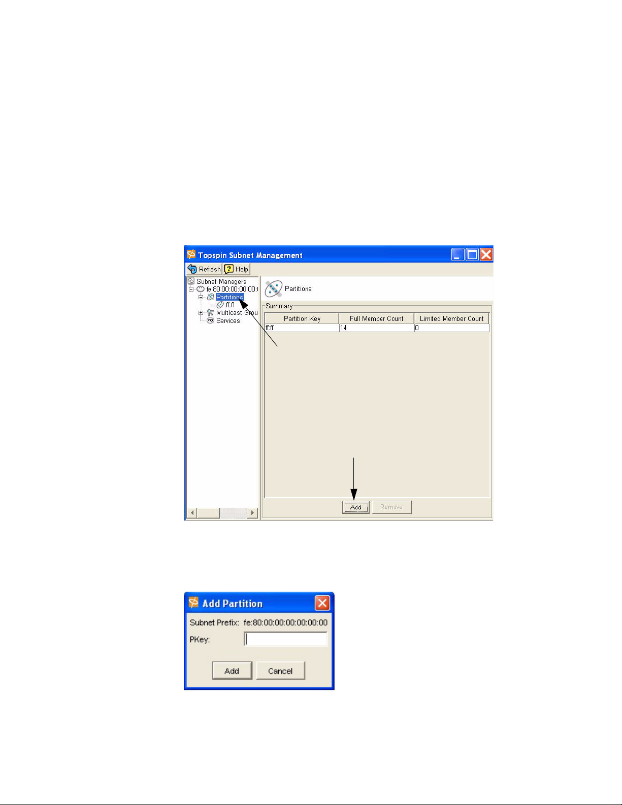
Create a Partition ID (P_Key)
A default partition is configured automatically. The members of a default partition include all connected
ports, and provide full membership. However, to create separation between traffic, you must configure
specific partitions.
1. Launch Element Manager, if you have not already done so.
2. Select InfiniBand --> Subnet Management.
The Subnet Management window appears.
3. Click open the Subnet Manager folders in the left window.
The Partitions folder appears.
4. Click on the Partitions folder in the left window. The Partitions Summary window appears.
5. Click the Add button.
The Add Partition dialog box appears.
Enter a Partition key (P_Key) to identify the new partition. For information regarding selecting
values, refer to the “Selecting a P_Key Value” on page 54.
00:01
a. Click the Add button.
The new Partition appears in the left window.
Page 29
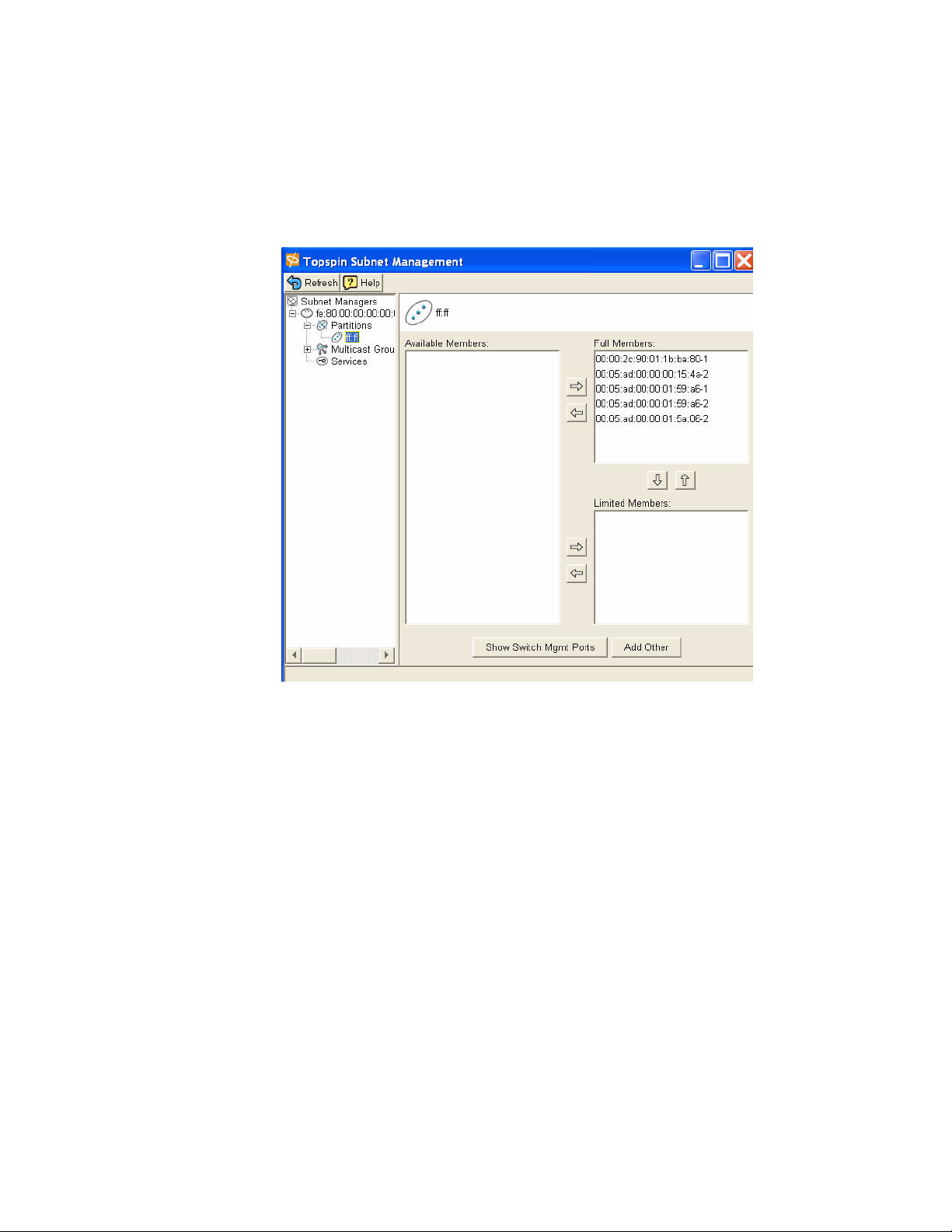
Specify Partition Members and the Membership Type
b. Click on the new Partition in the left window.
The available partition members appear in the right-side window.
p
17
Note that the “Available Members” refers only to members that are known to the Subnet Manager.
This includes HCAs and switches that are already plugged into the fabric as well as manually
configured entries.
If you know the GUID and port count of an HCA that has not yet been installed, you can configure
it before it is plugged in by using the “Add Other” button.
c. Click on a member from the Available Member list, and use the arrow button to move it to the Full
or Limited member columns.
For information regarding Membership Types, refer to the “Membership Types” on page 54
d. Click back to the Partitions folder (in the left-side window) when you have selected all of the
members for your Partition.
The new Partition appears in the Partition Summary window.
Maintain Partition Key Information
The configured p_keys will be needed in completing the configuration of the system.
e. Configured partition keys must be mapped to any of the following components that exist:
• Host Channel Adapters (HCAs). Refer to the HP Dual-port 4x Fabric Adapter User
Guide.
• Ethernet Gateway Bridge-groups.
Page 30

18
• Fibre Channel gateways.
f. If you have multiple InfiniBand switches in your fabric:
• Exchange the partition configuration between switches by enabling database
synchronization, if you have not already done so. Refer to “Enable/Disable Database
Synchronization” on page 84.
Set User Levels and Passwords
Change Default User Name and Password
For security purposes, since multiple users exist on the system, it is highly recommended that you
change the default passwords after initial configuration.
See “Understanding Usernames and Passwords” on page 46 for more information.
1. Log in to the CLI as a super user. Use the default username (super) and the default password
(super) if they have not already been changed (refer to page 47).
2. Enter the privileged-user mode.
3. Enter the global-configuration mode.
4. Enter the
password.
Use the default user name and password if they have not already been changed (refer to page 47).
The user name and password are alphanumeric strings of up to 34 characters each.
username command and the
password
keyword to change the user account and user
5. Repeat step 4 to change additional usernames and passwords.
Example
Topspin-360# Login: super
Password: xxxx
Topspin-360>
Topspin-360#
Topspin-360(config)#
Topspin-360(config)# username ib-fc_admin communitystring
ibFc-commStr
enable
configure
username
ib-fc_admin
password
ibFcAdmin
6. Exit the global-configuration mode.
7. Use the
show user
command to verify changes.
Only a user with unrestricted privileges may view user information.
Topspin-90> show user all
=========================================================================
User Information
=========================================================================
username : admin
password : topspin
snmp-community : justatest
permission-level : ib-rw, ip-ethernet-rw, fc-rw
admin-status : enabled
num-logins : 0
num-unsuccessful-logins : 0
last-login :
last-unsuccessful-login :
Topspin-90>
Page 31

Understanding the Management Options
This chapter gives an overview of the following system Management options:
The CLI
• “About the CLI” on page 19
• “Using the CLI” on page 21
The Java GUI
• “About Element Manager” on page 24
• “Using Element Manager” on page 27
The Web GUI
• Refer to the HP 24-Port Fabric Copper Switch Chassis Manager User Guide
SNMP
• “About SNMP” on page 30
• “Using SNMP” on page 30
19
3
About the CLI
The Topspin system can be managed through the Command Line Interface. For more information
regarding the CLI, refer to the HP 24-Port Fabric Copper Switch Command Line Reference Guide, or
“Understanding the Command Modes” on page 20.
The CLI includes the following features:
• IOS-like syntax
• Command Completion
• Context Help
Page 32

20
• Multiple Command Modes
Example
# telnet topspin_90
Login: super
Password: xxxx
Topspin-90> enable
Topspin-90#
Understanding the Command Modes
The CLI has four command modes
• user-execute mode (read-only)
• privileged-execute mode
• global-configuration mode
• sub-command mode
The commands you can enter depend upon the current command mode and who you log in as. You may
enter a question mark (?) at the CLI prompt to list the commands appropriate for the current mode and
user identity.
# telnet topspin_90
Login: super
Password: xxxx
Topspin-360> enable
Topspin-360#
User-Executive Mode
The user-execute mode is the entry point to the privileged-execute mode and all CLI sessions begin in
the user-execute mode. This mode provides commands for viewing some of the HP 24-Port 4x Fabric
Copper Switch configuration and some user information. Guest users may only work in the
user-execute mode.
Privileged-Execute Mode
The privileged-execute mode can view the entire switch configuration and all user information. It is
used to perform some high-level administrative tasks, such as saving the current configuration and
setting the system clock. It is also the access point to the global-configuration and sub-command modes.
You must enter the privileged-execute mode before entering the configuration modes.
Use the
unrestricted users may enter the privileged-execute mode.
Mode changes are reflected in changes to the Topspin system prompt.
For example, going from the user-execute to privileged-execute mode, the prompt changes from
Topspin-90>
enable
keyword to enter the privileged-execute mode. Note that only administrative and
to
Topspin-90#
.
Topspin-90# configure
Topspin-90(config)#
Global-Configuration Mode
Enter the global-configuration mode from the privileged-execute mode. The global-configuration mode
is used to configure everything except interface cards and their ports. The global-configuration mode
configures system-level attributes, such as SNMP, SNMP agents, and the networks.
Enter the
config
keyword while in the privileged-execute mode to enter the global-execute mode.
Page 33

Sub-Command Mode
The final mode is sub-command mode. Anything to do with InfiniBand, Ethernet, and Fibre Channel
interface cards, ports, and gateways is done in this mode, including the Management-Ethernet ports.
This mode is used to assign IP addresses to interface gateway ports, set connection speeds, set
connection types, etc.
Using the CLI
Entering the Sub-Command Mode
1. Enter global-configuration mode
2. Enter the interface keyword
3. Enter the type of interface to be configured
For example, to enter the interface-configuration mode for configuring the Management-Ethernet
port, enter:
Topspin-90(config)# interface mgmt-ethernet
Topspin-90(config-if-mgmt-ethernet)#
21
Exiting Command Modes
Most commands are mode-dependent. For example, you can only log out of a Topspin system session in
the user-execute or privileged-execute mode. To configure the Topspin system, you will have to enter
and exit Topspin system modes.
The
exit
command is used to return to the previous mode.
Topspin-360(config-if-fc-5/1)# exit
Topspin-360(config)# exit
Topspin-360#
You may also enter the
one step. If you are currently in the privileged-execute mode,
out of the CLI session.
To exit the privileged-execute mode and return to the user-execute mode, enter the
command. For example:
Topspin-360(config)# disable
Topspin-360>
Using Command Completion
The system provides command completion by way of the [Tab] key. If you enter a partial command and
press the [Tab], the CLI will complete the command and place the cursor at the end of the command.
To facilitate command entry, CLI commands do not have to be entered in their entirety. You may enter
just enough of each command or argument to make it uniquely identifiable.
exit
command with the
all
argument to return to the user-execute mode in
exit
with the
all
keyword will log you
disable
Page 34

22
For example:
Topspin-360(config)# fc ?
srp - Configure FC SRP
srp-global - Configure FC SRP-global parameters
Topspin-360(config)# fc srp- ?
enable - Enable FC SRP
gateway-portmask-pol - Configure FC SRP-global gateway-portmask-policy
itl - Configure FC SRP-global ITL
lun-policy - Configure FC SRP-global lun-policy
target-portmask-poli - Configure FC SRP-global target portmask policy
Topspin-360(config)# fc srp- gate ?
restricted - Configure FC SRP gateway-portmask-policy restricted
Topspin-360(config)# fc srp- gate res ?
<cr>
Topspin-360(config)# fc srp- gate res
terminal length int
terminal no length
In the preceding example,
gateway-portmask-pol
srp-
, and
is short for
res
is short for
srp-global, gate
restricted
is short for
.
Note: Command completion only works for commands; it is not effective for keywords.
Displaying Command History
The Topspin system “remembers” the last 40 commands you enter.
Display the commands in the command history by using the following command:
history
You can also use up and down arrows to toggle between commands.
Setting Terminal Parameters
The TopspinOS can be customized to set the number of lines displayed at one time by commands like
more
(used to prevent data from scrolling quickly out of view). The number of lines specified only
applies to the current CLI session. Other users are unaffected by changes to the display length.
You can also set a limit for inactivity during a CLI session. Changes to this parameter are applied
immediately to all users, whether logged in now or who log in later.
1. Enter the length command
length
int is a number between 1 and
It is recommended you set the terminal page length to
end
argument. Otherwise, you will have to keep pressing the <space> bar to continue each time the
maximum display length is reached.
no
resets the terminal length to the default (24 lines per page).
Topspin-360# terminal time-out 45
Topspin-360# terminal no time-out
time-out
int is a number between 1 and
inactivity allowed before automatically closing the CLI session.
no
resets the session limit for inactivity to the default (15 minutes).
Example
512
that indicates the number of lines to display at one time.
0
100000
when using the
that indicates the number of minutes of
tail
command with the
Page 35

To set the number of lines displayed on the terminal screen to 67 lines at a time and raise the time-out
limit to 60 minutes
1. Enter the user-execute or privileged-execute mode.
2. Enter the
page.
Topspin-90# terminal length 67
terminal
command with the
length
23
parameter and the number of lines to display per
3. Enter the
terminal
command with the
user to remain inactive before closing their CLI session.
Topspin-90# terminal time-out 60
4. Verify the changes were made by entering the show terminal command.
Topspin-90# show terminal
Console is enabled
Connection host address is 10.10.253.47
Length: 67 lines, Width: 80 columns
Timeouts: enabled, Value: 60 minutes
Session limit is set to 3
History is enabled, history size is 30
Maximum command length is 512 characters
Maximum login attempts is 5
Topspin-90#
Ending A CLI Session
To terminate the current CLI session:
1. Enter
2. You may want to save the current configuration so that it is re instantiated the next time the system
exit all
reboots.
to return to the user-execute mode.
time-out
parameter and the number of minutes to allow a
Topspin-360# copy system:running-config config:startup-config
The
copy
command “copies” the current configuration to the
used to reconfigure the chassis upon reboot. The
running-config
unsaved configuration commands. When it is “copied” the system saves the running-config into the
Topspin-360# logout
Topspin-360# Login:
startup-config
3. Enter the CLI
logout
file so that they can be maintained across reboots.
command.
Users who initiated a CLI session through a Telnet or SSH connection to the Management-Ethernet
port will be logged out and the connection closed. Users connected directly to the Serial-Console
port will still be prompted to login to the CLI.
NOTE: Do not use
<control> c
to terminate an active CLI session. It has been disabled to
ensure that the CLI is always running on the terminal. Only the CLI
<control> c.
startup-config
file, which is
is a virtual file that contains all
copy
command recognizes
Page 36

24
Quick Help
You can enter the question mark (?) at the CLI prompt to display one of three types of user information.
1. Enter a question mark (
Only the commands appropriate to the current mode and user login are displayed.
2. You may also enter part of a command string, and a question mark, to display the choices for
completing that command string.
You may enter just enough of each command or argument to make it uniquely identifiable,
followed by a space and a question mark to display the arguments and keywords you need to
continue the command line.
You may enter just enough of each command or argument to make it uniquely identifiable,
followed by a space and a question mark to display the arguments and keywords you need to
continue the command line. For example:
Topspin-360(config)# i? <-- display all keywords that start with “i”
Configure Commands:
ib - IB subnet manager configuration
ib-agent - Configure IB agent settings
interface - Select an interface to configure
ip - Global IP configuration subcommands
Topspin-360(config)# in? <-- display all keywords that start with “in”
interface <-- only 1 keyword starts with “in”
Topspin-360(config)# in ? <-- display the arguments to “interface”
ethernet - Configure Ethernet interfaces
fc - Configure Fibre Channel interfaces
gateway - Configure Gateway settings
ib - Configure InfiniBand interfaces
mgmt-ethernet - Configure Ethernet Management port
mgmt-ib - Configure InfiniBand Management port
Topspin-360(config)# in <-- waits for you to complete the “interface”
command string
?
) at the CLI prompt at any time to display the commands you can execute.
After displaying the help information, the system enters the command string up to the question
mark on the input line and waits for you to complete the string. You do not have to retype the string.
If there is no space between a partially-entered command string and the question mark, a list of
possible completions are displayed, as shown above.
When enough characters have been entered to uniquely identify a command or keyword in a
command string, you may leave it as-is, enter a space, and then add additional keywords or
arguments, or you can press the <Tab> key to complete the commands or keywords to improve
readability.
About Element Manager
The Element Manager is the Graphic User Interface that can be used to manage most of the Topspin
system functionality.
The Element Manager is comprised of several different areas, which allows you to manage the entire
Topspin system.
Page 37

Menu Bar
Tool B a r
Status Bar
25
The Chassis Window
Once you log into the Element Manager, the chassis window is displayed. This is the primary window
in which you work. It graphically depicts the current configuration of the attached InfiniBand system
chassis.
Sample HP 24-Port 4x Fabric Copper Switch Chassis View
Power
Status
InfiniBand Port
Console Port
Eth Mgmt
Por
Port
The Tool Bar
The tool bar contains a set of icons for commonly used functions. These are described in the table
below.
Table 3-1: Element Manager Tool Bar
Initiates a Topspin system session on a different chassis. The new
window opens and requests the host address and user credentials. It is
the equivalent to selecting File->Open…
Polls the physical chassis for current connectivity and status, and then
updates the display.
It is the equivalent to selecting File->Refresh.
Opens a terminal window and starts a Telnet session with the physical
switch chassis that is hosting the current session. It prompts for CLI
user credentials. Once you supply this information, you may use CLI
commands to configure and monitor the swithc chassis. It is equivalent
to selecting File->Tel net . See “Remote Telnet Login” on page 11.
Displays context-sensitive usage information about the current
window. It is the equivalent to selecting
“Quick Help” on page 24.
Help->Contents
. See
Page 38

26
Table 3-1: Element Manager Tool Bar
Port Configuration:
Opens a window that displays the configuration of the selected port(s).
For most ports, the window is also use to change port configuration. It
is equivalent to selecting Edit->Port Properties….
Card Configuration:
If the selected object is a card, the Edit window opens. There is no
pull-down menu equivalent for this function when a card is selected;
use Edit-> Card Properties…. .
or
Double-click the card or right-click the card and select Edit from the
pop-up menu.
Opens a window that displays selected statistical data in a line chart
format. It is typically used to chart and analyze network traffic
statistics. There is no specific menu equivalent; however this icon is
typically included on most windows opened by
Graph->Port…
Analyzing Network Data” on page 137.
Opens the Topology view, a graphic tool that depicts the switch and
channel adapter connections of the current InfiniBand fabric
configuration. Refer to “About the Topology View” on page 121.
. or
Report
-->
Graph->Card…
Report
-->
. Refer to “About
Opens the Subnet management window. Configure and view current
Subnet Managers, Partitions, and Multicast groups. It is the equivalent
to selecting
Opens the Storage Manager window. Configure and view current Fibre
Channel SRP information. It is the equivalent to selecting
Channel -> Storage Manager
InfiniBand -> Subnet Manager
.
.
Fibre
About Selecting Items
Interaction with the Topspin system is performed using a combination of pull-down menus, icons in the
tool bar, and pop-up menus. The windows these open contain a combination of text fields, radio buttons,
and toggles with which to configure selected cards and/or ports.
Depending upon the function you wish to execute, you select one or more cards and/or ports in the
following ways:
• by placing the cursor over the desire object(s) and clicking the left mouse button.
• by placing the mouse cursor over the object and right-clicking the mouse. This displays a
pull-down menu from which you may select an item.
• by placing the mouse cursor over it and double-click the left mouse button. This selects the object
and opens a default window. The window displayed depends upon the selected object. This is
explained in more detail in the sections that follow.
Everything in the switch chassis display may be selected. You can select the chassis, interface cards,
ports, management ports, and serial console ports. The only exception are the cards without ports. These
are placeholders for later expansion and cannot be selected.
Select multiple objects on the switch display by using <Control> left-click. However, when you select
an object that is not the same type as the currently selected set, the selected set is de-selected.
Page 39

For example, if you <Control> left-click multiple Ethernet ports and then attempted to select a Fibre
Channel port:
The Ethernet ports are de-selected and the Fibre Channel port is the only thing selected.
Using Element Manager
Installing the Element Manager Program
For information regarding upgrading the Element Manager, refer to “Starting the Element Manager” on
page 29.
HP 24-Port 4x Fabric Copper Switch devices can be managed visually through the Element Manager,
which provides a wide range of configuration, monitoring, and troubleshooting options.
The Element Manager runs on multiple platforms, including Windows NT/2000/XP and Linux. To
install the Element Manager:
1. Check that you have sufficient system resources.
You will need:
• 64 MBytes free RAM
• 75 MBytes disk space + 50MBytes additional temporary space during installation
• 300 Mhz processor
• 800x600 screen resolution, 16bit color depth
2. Locate software.
a. Go to http://support.hp.com/
b. Select “Software & Driver downloads.”
c. On the Software & Driver Downloads page, enter your product name, then click the double
arrow.
3. Install the software.
a. Unzip the tar file containing the software using gunzip.
b. Extract the software into a local directory using tar.
c. Change directory to Element Manager (EM)
4. Locate the correct install program in the Linux or Windows directory for your architecture. Execute
that program.
For example, for Linux ia32:
• cd Linux
• ./install_linux_x86.bin
5. Click Next.
27
The Choose Install Folder window opens.
6. Specify the folder in which to install the software. You may:
• Enter the full path to where you want the software installed.
or
Click the Choose button to browse for a folder.
•Click Restore Default Folder to restore the folder location to its original value. On Windows,
the default is
C:\Program Files\Topspin Element Manager
. On Solaris and
Page 40

28
Linux, the default is /home
installing the software.
If the folder does not exist, you will be prompted to create it.
7. Click the Next button.
On Windows, the Choose Shortcut Folder window opens.
/TopspinEM
, where home is the home directory of the person
Figure 3-1: Element Manager Installation, Choose Shortcut Folder Window
On Linux, the Choose Link Folder opens.
Figure 3-2: Element Manager Installation, Choose Link Folder Window
8. Specify where you want shortcuts, or links, to the Element Manager placed.
You may select multiple options. You may also specify a unique placement in the Other field or by
clicking the Choose... button.
If you want to change the settings in a preceding window, click Previous.
9. Click the Next button.
Page 41

The Pre-Installation Summary window is opened. This window lists the installation choices you
have made thus far.
10. If you are satisfied with your installation choices, click Install.
The Installing Element Manager window opens to indicate installation status.
If you are not satisfied with the configuration, click Previous to return to the preceding window and
make the desired changes.
The Installation Complete window opens when the software is installed.
11. Click Done.
The window closes and Element Manager installation is complete.
Starting the Element Manager
1. To start the Element Manager:
On a Windows system, select the Element Manager icon or select it from the Programs menu.
For example:
Start->Programs->Topspin Element Manager->TopspinEM
The
Open Device
the management port and the administrator’s community string. The community string functions as
an SNMP password.
window opens. This window is used to specify the IP address or DNS name of
29
# ./TopspinEM
If you are on a UNIX system, change to the directory containing the Element Manager executable,
or add the directory to your search path. Enter the Element Manager command on the command
line.
Example
The
Open Device
2. Enter the IP address or network name of the management port in the
the IP address or network name of the out-of-band management port or the in-band management
port.
Figure 3-3: Element Manager, Open Device window
The IP address of the management port in the Figure 3-3 example is
3. Enter the appropriate community string in the
window opens.
SNMP Community
Device Name
10.10.253.47
field.
field. Enter
.
The default unrestricted community string is
strings, refer to “Configuring SNMP Settings” on page 30.
4. Click
Open
.
A graphic representation of the switch chassis and current configuration is displayed.
secret
. For information regarding community
Page 42

30
The Element Manager is now ready to configure the InfiniBand network, as well as Ethernet or
Fibre Channel expansion module(s).
The Element Manager is dynamically updated to show changes to the configuration. As cards and
ports are configured, the corresponding run lights and port frames reflect the changes by turning
green. Depending upon your Element Manager Preference settings, it may take a few seconds for
configuration changes to be shown in the Element Manager display.
Reading the Element Manager Status Colors
The colors in the Element Manager display indicate the state of each port:
Table 3-2: Interpreting the Element Manager Port Colors
Color Indication
Green A link is established between the port and a connected host or switch.
A host or switch must be connected to the port for it to turn green. A
green port does not indicate network activity.
Grey The port is enabled but there is no link, as in the case of a disconnected
cable.
Red The port is disabled.
About SNMP
Transparent The port is unmanaged.
The Topspin system can also be managed via SNMP v2C, including a variety of MIBs and Traps.
Any Network Manager running the Simple Network Management Protocol (SNMP) can manage the
switch, if the Management Information Base (MIB) is installed correctly. By default, the switch GUI is
a network manager and uses SNMP as the protocol to communicate between the chassis and the
management workstation.
Supported MIBs
In addition to private MIBs, the Topspin system supports the standards MIBs listed below.
• RFC2665: Ethernet-Like MIB
• RFC1213: MIB2
• RFC2863: The Interface Group
• RFC2096: IP Forward MIB
• IB SM - Draft InfiniBand Subnet Manager
• IB SMA - Draft InfiniBand Subnet Management Agent
Using SNMP
Configuring SNMP Settings
The following SNMP parameters can be configured on the system:
• Authorized Trap Receivers - You can set one or more network management stations on your
network to receive traps. By default, the Element Manager is configured to be an authorized trap
Page 43

receiver. You can have a maximum of six trap receivers. Entries in this list can be configured from
the
Health --> Trap Receivers
• Community Strings - You can set community strings as a simple method of authentication
between the system and the remote Network Manager. One unique community string is associated
with each username and password. Community strings can be associated with a variety of privilege
levels. For a list of default community strings associated with each user, see “Managing Access
and Accounts” on page 47.
menu.
31
Page 44

32
Page 45

Performing Admin Tasks Through the GUI
This chapter describes the following administrative procedures that can be performed through the
Element Manager GUI:
• “Configuring the IB Interface Speed” on page 33
• “Setting the System Clock” on page 36
• “Rebooting the System” on page 37
33
4
Configuring the IB Interface Speed
Explicitly Configure IB Interface Speed
To explicitly set the speed for the InfiniBand interface ports as 1x or 4x:
1. Confirm that you are using the appropriate InfiniBand cable for the speed you intend to set.
For example, if you intend to set the speed as 4x, it is imperative that you confirm you are using a
4x cable. Using a 1x cable on a 4x speed InfiniBand interface will cause serious performance
issues.
2. Launch Element Manager, if it is not already open.
A graphic representation of your InfiniBand switch appears.
3. Double-click an InfiniBand port.
Page 46

34
The IB Port window appears.
4. Uncheck the Enable Auto-Negotiate box. Leave auto-negotiate checked if you want the speed of
the transmit port and the receiving port to automatically negotiate the highest possible speed.
5. Select the 2500M or 10G speed. The 30G speed is not yet supported.
6. Click the Apply button.
Set IB Interface Speed to Auto-Negotiate
Set the InfiniBand interface speed to auto-negotiate if you want the speed of the transmit port and the
receiving port to automatically negotiate the highest possible speed.
1. Launch Element Manager, if it is not already open.
A graphic representation of your InfiniBand switch appears.
2. Double-click an InfiniBand port.
Page 47

The IB Port window appears.
35
3. Check the Enable Auto-Negotiate box.
4. Click the Apply button.
View the IB Interface Speed
View the current speed of the InfiniBand interfaces:
1. Launch Element Manager, if it is not already open.
A graphic representation of your InfiniBand switch appears.
2. Double-click an InfiniBand port.
The IB Port window appears.
3. Check the Enable Auto-Negotiate box.
Page 48

36
4. Click the Apply button.
Setting the System Clock
Maintaining accurate time is important for statistics and auditing. The InfiniBand chassis provides an
on-board system clock to save the time settings across reboots. Time is maintained in one of two ways:
• An on-board system clock
• External NTP servers
Time is set at the factory, and can be manually set. To ensure accurate synchronization, it is
recommended that you use an external NTP server. This enables logs to be synchronized with other
management systems.
Setting Time Manually
To set the system clock in the Element Manager:
1. In the Element Manager, select
2. Enter the time manually in the
It is recommended that you use NTP servers to maintain the system clock because it assures
accuracy and avoids the potential time drift inherent to unsynchronized clocks.
3. Click
4. Click
Apply
Close
.
.
Maintenance->Time…
Time
and
Date
fields.
.
Synchronize the Clock to an NTP Server
This section shows you how to use the Element Manager to synchronize the Topspin system clock with
an NTP server:
1. In the Element Manager, select
The
Chassis Time
window opens.
Maintenance->Time…
.
2. Ignore the
3. In the
NTP Servers
NTP
Server2
Date and Time
group, enter the IP addresses of the NTP servers in the NTP
, and NTP
Server3
group; it will be reset automatically by the NTP servers.
Server1
fields.
,
Page 49

37
4. Click
5. Click
Apply
Close
.
.
Rebooting the System
Reboot a System with a Single Controller Card
1. Launch the Element Manager.
2. Choose the reboot option:
a. Right-click in any unused part of the Element Manager display, including unused interface
slots.
A pop-up window opens that allows you to select
b. or select Maintenance --> Reboot.
If changes have been made, you will be asked if you want to save the changes:
Reboot
.
3. Select Ye s to save changes, or No to discard changes.
A prompt appears to verify your desire to reboot the system.
Yes
4. Click
to reboot the system or No to return to the Element Manager display.
Upon rebooting, the connection is lost or the Element Manager opens a “Timeout” dialog.
These indicate the reboot process is taking place.
Page 50

38
Page 51

Performing Admin Tasks Through the CLI
This chapter describes the following administrative procedures that can be performed through the CLI.
• “Setting the IB Interface Speed” on page 39
• “Notifying Users” on page 40
• “Setting the System Clock” on page 41
• “Rebooting the System” on page 43
39
5
Setting the IB Interface Speed
InfiniBand interface port speeds can be configured to 1x or 4x.
Explicitly Configure IB Interface Speed
To explicitly set the speed for the InfiniBand interface ports as 1x or 4x:
1. Confirm that you are using the appropriate InfiniBand cable for the speed you intend to set.
For example, if you intend to set the speed as 4x, it is imperative that you confirm you are using a
4x cable. Using a 1x cable on a 4x speed InfiniBand interface will cause serious performance
issues.
2. (Optional) Disable auto-negotiate if it is currently enabled. The interface speed cannot be
configured as long as auto-negotiate is enabled.
Example
Topspin-360> enable
Topspin-360# config
Topspin-360(config) interface ib all no auto-negotiate
Topspin-360(config-if-ib-1/1-1/12)#
Page 52

40
3. Enter the following command:
config interface ib [{IB switch card/IB switch port | all }speed 1x | 4x ]
Example
Topspin-360> enable
Topspin-360# config interface ib all speed 4x
Set IB Interface Speed to Auto-Negotiate
Set the InfiniBand interface speed to auto-negotiate if you want the speed of the transmit port and the
receiving port to automatically negotiate the highest possible speed. IB speed can be set on an
individual port basis, or all at once.
1. Enter the following command:
config interface ib [{IB switch card/IB switch port | all }auto-negotiate]
Example
Topspin-360> enable
Topspin-360# config
Topspin-360(config)# interface ib all
Topspin-360(config-if-ib-1/1-1/12)# auto-negotiate
Topspin-360(config-if-ib-1/1-1/12)#
View the IB Interface Speed
View the current speed of the InfiniBand interfaces:
1. Enter the following command:
show interface ib [IB switch card/IB switch port | all]
Example
Topspin-360> enable
Topspin-360#
===============================================================
==============================================================
....
....
auto-negotiate-supported : yes
auto-negotiate : enabled
admin-speed : 10gbps
oper-speed : unknown
....
....
***************************************************************
show interface ib 15/1
InfiniBand Interface Information
Notifying Users
User notification commands send text messages to the terminal screens of all CLI users or to individual
users. These are convenient utilities for notifying everyone of an impending reboot or to notify single
users about special issues that apply only to them.
Page 53

41
Broadcasting Messages to all Users
Message broadcasting is an important feature to forewarn all CLI users that some major event is about
to take place, such as bringing down a network for administration. A broadcast message is sent to every
active CLI session on the InfiniBand system chassis.
Enclose multi-word messages within double-quotes. Single-word messages do not require
double-quotes. Only the unrestricted user may broadcast messages.
Syntax
Topspin-90# broadcast “message”
The message identifies the sender, followed by the message text.
For example, if you send this:
Topspin-90# broadcast “FC card 5 going down in 10 minutes.”
Everyone, including the user who sent the message, receives this:
Topspin-90# Broadcast message from super
FC card 5 going down in 10 minutes.
Sending Messages to Individual Users
The
write
command is used to send a message to a single user. Check that the user is logged in before
attempting to write to their terminal.
1. Enter the
2. Enter the write command to message the individual.
Topspin-90> show user waldo
===============================================================
===============================================================
username : waldo
access-level : readwrite
admin-status : enabled
status : active
num-logins : 1
num-unsuccessful-logins : 6
last-login : Thu Oct 10 09:13:10 2002
last-unsuccessful-login : Thu Oct 10 09:12:32 2002
Topspin-90> write waldo “Connection to FC array 15 is now
working.”
Topspin-90>
show user
User Information
user_name command to verify the user is logged in.
Setting the System Clock
Maintaining accurate time is important for statistics and auditing. The switch chassis provides an
on-board system clock to save the time settings across reboots. Time is maintained in one of two ways:
• An on-board system clock
• External NTP servers
Page 54

42
Time is set at the factory, and can be manually set. To ensure accurate synchronization, it is
recommended that you use an external NTP server. This enables logs to be synchronized with other
management systems.
Setting Time
Note: If you have an NTP server configured, it is recommended that you use the process described in:
“Synchronize the Clock to an NTP Server” on page 42.
To set the Topspin system clock in the CLI:
1. Login to the CLI as the
2. Enter
Topspin-360> enable
Topspin-360#
3. Enter the
Topspin-360# clock set 19:22:10 25 03 03
4. Save your configuration.
Topspin-360# copy running-config startup-config
enable
hh:mm:ss dd mm yy. For example:
to enter the privileged-execute mode.
clock
super
user.
command, followed by the
Synchronize the Clock to an NTP Server
You can set the InfiniBand switch to synchronize the time with up to three NTP servers.
To set the InfiniBand system clock in the CLI:
Topspin-360> enable
Topspin-360#
1. Log in to the CLI as the
2. Enter
enable
to enter the privileged-execute mode.
super
user.
set
keyword and the time and date in the format
3. Enter the ntp command, and the keyword server-one before entering the IP address.
This is the first server to which the IB switch will synchronize.
Topspin-360# config
Topspin-360(config)# ntp server-one 10.0.3.10
Topspin-360(config)#
4. Enter the IP address of a second NTP server.
Topspin-360(config)# ntp server-two 10.0.3.11
Topspin-360(config)#
5. Enter the IP address of a third NTP server.
Topspin-360(config)# ntp server-three 10.0.3.13
Page 55

Rebooting the System
Reboot a System with a Single Controller
43
Enter the CLI
reload. If you had not already saved configuration changes, and the system detects the changes, it
prompts you to save. If you enter yes, the new configuration is stored in startup-config. You may
optionally save the configuration to an alternate file by entering the file name, followed by a
carriage-return.
Example
Topspin-360> enable
Topspin-360# reload
System configuration has been modified. Save?
[yes(default)/no/*.cfg] yes
Proceed with reload? [confirm]
Topspin-360#
Connection to host lost.
The system re-initializes itself and then loads the system-image and the startup-config file. Wait a few
minutes and attempt to log onto the chassis.
reload
command in privileged EXEC mode. The system prompts for you to verify the
Page 56

44
Page 57

Setting Access and Security
This chapter describes the following Access and Security features:
• “Understanding Access and Accounts” on page 45
• “Managing Access and Accounts” on page 47
• “About Partitions” on page 53
• “Create Partitions (CLI)” on page 56
or
• “Create Partitions (GUI)” on page 57
• “About SSH” on page 59
45
6
Understanding Access and Accounts
About User Accounts
A user account is used to control who gains access to the Topspin system. Access can be achieved
through the CLI (console, telnet, SSH) and SNMP. CLI access is authorized through a password
validation. SNMP access is authorized through a community-string validation.
User accounts can be added, deleted, and modified as needed. Up to 15 user accounts are supported.
Only user(s) that have the unrestricted ReadWrite permission level can add, delete, and modify user
accounts. Each Topspin system is preconfigured with three factory default user accounts.
Each user account can be administratively enabled and disabled as needed. The user can disable a user
account without having to delete it from the system.
Each user account is uniquely identified by an ascii string that can be up to 20 characters long. No two
user accounts can have the same user name.
Page 58

46
In order for users to initiate an administration session, the User has to supply login credentials. The
credentials supplied depend upon the interface being used.
Elements of the Access System
The Topspin access system associates the following key elements:
• Username - Creates a unique username in the system.
• Password
• Community String - Unique string used for the Element Manager and SNMP Network Managers.
• Privilege Level - Allows combinations of different privileges.
The CLI uses username and password. The Element Manager uses the community string to identify
which user has logged in. Granular access rights are given by privilege level.
Understanding Usernames and Passwords
CLI users enter standard username and password information to begin a CLI session. By default, you
may log on as one of three users,
below.
super, admin
, or
guest
. The user names are shown in the table
Table 6-1: Default User Names, Passwords, and Privileges
User Name Default Passwords Privileges
super By default, the password is “super”. The
default community string is “secret”.
admin By default, the password is “admin”. The
default community string is “private”.
guest
(disabled by default)
The default password is “guest”. The
default community string is “public.”
The super user has unrestricted privileges.
Use this account to manage any part of the
Topspin system. This user may view and
modify a configuration, as well as
administer user accounts and access
privileges. This user configures the
console and management ports for initial
chassis setup.
The admin user has general read-write
privileges. This user may view and modify
the current configuration. However, the
admin user can change only its own user
information, such as the admin password.
The guest user has read-only privileges.
This user may only view the current
configuration. The guest user cannot make
any changes during the CLI session.
About Roles and Privileges
Roles allow granular levels of privileges. For example, you can create separate Fibre Channel, Ethernet,
or InfiniBand administrators, who only have access to specific subsystems. The Topspin system
combines multiple roles with read and read-write access for flexible control. These roles are enforced
with both the CLI and the Element Manager.
The unrestricted administrator (super) is responsible for assigning these roles. Network administrators
are given read-only and read-write access to each of the three network types.
Page 59

Understanding Permission Levels
The following table displays the different access-levels.
Table 6-2: Description of Privilege Levels
Level Description
ib-ro InfiniBand read-only access.
ib-rw InfiniBand read-write access.
ip-ethernet-ro Ethernet read-only access.
ip-ethernet-rw Ethernet read-write access.
fc-ro Fibre Channel read-only access.
fc-rw Fibre Channel read-write access.
unrestricted-rw Read-write access to all network configuration commands.
Managing Access and Accounts
Setting or Changing a Password
47
1. Log in to the CLI as a super user. Use the default username and password if they have not already
been changed (refer to page 14).
2. Enter the privileged-user mode.
3. Enter the global-configuration mode.
4. Enter the
password.
Use the default user name and password if they have not already been changed (refer to page 14).
The user name and password are alphanumeric strings of up to 34 characters each.
5. Repeat step 4 to change additional usernames and passwords.
Example
Topspin-360# Login: super
Password: xxxx
Topspin-360>
Topspin-360#
Topspin-360(config)#
Topspin-360(config)# username ib-fc_admin communitystring
ibFc-commStr
enable
configure
username
6. Exit the global-configuration mode.
username
ib-fc_admin
command and the
password
password
ibFcAdmin
keyword to change the user account and user
Page 60

48
7. Use the
Topspin-360# show user
=========================================================================
User Information
=========================================================================
username : testuser
password : $1$OHJt61CE$ANK02CcPqKnFoxJ0AKAtB.
snmp-community : secret
permission-level : unrestricted-rw
admin-status : enabled
num-logins : 4
num-unsuccessful-logins : 0
last-login : Mon Nov 17 22:43:25 2003
last-unsuccessful-login :
Topspin-360#
show user
command to verify changes.
Displaying User Information
To display the information of configured users:
1. Log in to the CLI as a super user.
Only a user with unrestricted privileges may view user information.
2. Enter the
show user
all command to display current user information.
Topspin-90> show user all
=========================================================================
===
User Information
=========================================================================
===
username : admin
password : topspin
snmp-community : justatest
permission-level : ib-rw, ip-ethernet-rw, fc-rw
admin-status : enabled
num-logins : 0
num-unsuccessful-logins : 0
last-login :
last-unsuccessful-login :
…
…
…
username : super
password : super
snmp-community : secret
permission-level : unrestricted-rw
admin-status : enabled
num-logins : 1
num-unsuccessful-logins : 0
last-login : Tue Nov 19 10:03:47 2002
last-unsuccessful-login :
Topspin-90>
Page 61

Adding New Users
To add a new user account for both CLI and Element Manager access:
1. Log in as the unrestricted user.
Only a user with unrestricted permissions may add new user accounts.
Topspin-360# Login: super
Password: xxxx
Topspin-360>
2. Enter the privileged-user mode.
Topspin-360> enable
Topspin-360#
3. Enter the global-configuration mode.
Topspin-360# configure
Topspin-360(config)#
4. Create the user account and user password.
The user name and password are alphanumeric strings up to 34 characters each.
49
Topspin-360(config)# username ib-admin password ib-passwd
where
and
ib-passwd
ib-admin
is the name assigned to this user account,
is the password for this user account.
password
is a mandatory keyword,
5. Assign an SNMP community string to the new user account.
The user must have an SNMP community string to begin an Element Manager session. If you do
not want users to have SNMP access to the Topspin system, do not assign them a community string.
By default, a new user account has a null or empty community string.
Topspin-360(config)# username ib-admin community-string ib-commStr
where,
ib-admin
ib-commStr
is the name of the user account,
community-string
is the SNMP community string for this user account.
is a mandatory keyword.
6. Assign access privileges.
By default, the new user account has read-only access. You may grant write privileges to the user
for functional areas, such as InfiniBand, Ethernet, and Fibre Channel.
7. Enter multiple access privileges in the order shown in “About Roles and Privileges” on page 46.
Topspin-360(config)# username ib-admin privilege ib-rw ip-ethernet-ro fc-rw
where,
ib-admin
ib-rw, ip-ethernet-ro
is the name of the user account,
, and
fc-rw
are access privileges. Valid access privileges are
privilege
is a mandatory keyword, and
described in “About Roles and Privileges” on page 46.
All new user accounts are now enabled and ready for use.
8. Exit the global-configuration mode.
Page 62

50
9. View the new user account information.
Topspin-360(config)#
Topspin-360#
=========================================================================
===
User Information
=========================================================================
===
username : ib-admin
password : ib-passwd
snmp-community : ib-commStr
permission-level : ib-rw, ip-ethernet-ro, fc-rw
admin-status : enabled
num-logins : 0
num-unsuccessful-logins : 0
last-login :
last-unsuccessful-login :
Topspin-360#
show user ib-admin
exit
Deleting a User Account
1. Log in as the unrestricted user.
Only a user with unrestricted permissions may create and modify user accounts.
Topspin-360# Login: super
Password: xxxx
Topspin-360>
2. Enter the privileged-user mode.
Topspin-360> enable
Topspin-360#
3. Enter the global-configuration mode.
Topspin-360# configure
Topspin-360(config)#
4. Enter the
username
command with the name of the user, and the no keyword.
For example:
Topspin-360(config)# username ib-admin no
User Account Configuration Commands
Use the following commands and keywords to administer User Accounts:Community Strings.
In the Element Manager, unique SNMP “community strings” act as user passwords. Because these are
unique to each username, the community string determines which administrator is logged on. The
privilege level is defined separately.
Use the following commands and keywords to administer User Accounts:
Page 63

Table 6-3: User Account Administrative Commands
Command Task
username user password
passwd
username user no Deletes a user account.
username user
community-string string
username user
no-community-string
Creates a new user account.
Assigns a community string to a user account.
Removes a community string from a user account.
51
username user privilege
priv1 [priv2] [priv3]
username user no
permission
username user enable Administratively enables a User Account.
username user disable Administratively disables a User Account.
Assigns one or more permission level(s) to a user account. Refer to
“Privileges” on page 46 for a list of privilege levels.
Example: ib-ro, ib-rw, ip-ethernet-ro, ip-ethernet-rw, fc-ro, fc-rw,
unrestricted-rw
Assigns a default permission level to a user.
For rapid access, the Element Manager saves the IP address and community string of recent
administrators. These address/community string pairs are displayed in a scroll-list the next time you
want to open an Element Manager session. Note that whoever logs on after you can reuse this
connection information and, if you connected with superuser permissions, the person who follows after
you shall be able to do so, too.
You can disable this functionality by referring to “Disabling the Element Manager Auto-Connection”
on page 51.
Disabling the Element Manager Auto-Connection
To disable automatic connection saving in the Element Manager:
1. Select
2. Select the
3. Unclick the
File->Preferences…
Misc
tab.
Save communities in lastopen file
toggle.
Changing Community Strings
Use the CLI to set or change SNMP community strings. The user must have a SNMP community string
to begin an Element Manager session. If you do not want users to have SNMP access to the Topspin
system, remove their community string.
To change community strings:
1. Log in as the unrestricted user.
Only a user with unrestricted permissions may create and modify user accounts. However, any user
with write access (administrative and unrestricted) can remove their own community string.
Login: super
Password: xxxx
Topspin-360>
2. Enter the privileged-user mode.
Topspin-360> enable
Topspin-360#
Page 64

52
3. Enter the global-configuration mode.
Topspin-360# configure
Topspin-360(config)#
4. Enter the
Topspin-360(config)# username ib-admin community-string ib-commStr
Switching User Identity
One of the following scenarios may make it necessary to change your user identity during a CLI
session:
• you created a new user account and you want to verify the access privileges
• you have multiple administrative user-accounts and you want to switch to another administrative
To change your user identity:
1. Enter the user-execute or privileged-execute mode.
2. Enter the
Topspin-90# login admin
3. Enter the user password.
username
command with the name of the user, the
and the new community string to assign this user.
In the example above,
keyword.
ib-commStr
ib-admin
is the SNMP community string the user will have to use to begin Element
is the name of the user,
Manager sessions or execute other SNMP functions.
area
login
command with the name of a Topspin system user.
community-string
community-string
keyword,
is a mandatory
Password: xxxxx
Topspin-90>
After you enter the password, you are logged in as the specified user in the user-execute mode.
Changing Privilege Access-Levels
1. Log in as the unrestricted user.
Only a user with unrestricted permissions may create and modify user accounts.
Topspin-360# Login: super
Password: xxxx
Topspin-360>
2. Enter the privileged-user mode.
Topspin-360> enable
Topspin-360#
3. Enter the global-configuration mode.
Topspin-360# configure
Topspin-360(config)#
4. Enter the
username
privileges to assign this user. For example:
command with the name of the user, the
privilege
keyword, and the
Topspin-360(config)# username ib-admin privilege ib-rw ip-ethernet-ro
fc-rw
Page 65

53
In the example above,
keyword, and
NOTE: When you change a user’s privileges, all the old privileges are removed and replaced with the
new privilege(s). If the user had multiple privileges, include the other privileges on the command line
when you make the change. Privileges are order-dependent. Enter them in the same order as shown in
Table 6-2 on page 47.
ib-rw, ip-ethernet-ro
ib-admin
is the name of the user account,
, and
fc-rw
are access privileges.
privilege
is a mandatory
Example
The following example gives a user read-write access to InfiniBand and Ethernet configuration
commands.
Login: super
Password: xxxx
Topspin-360> enable
Topspin-360# configure
Topspin-360(config)# username IB_admin privilege ib-rw ip-ethernet-rw
fc-ro
Topspin-360(config)# exit
Topspin-360# show user IB_admin
======================================================================
User Information
======================================================================
username : IB_admin
password : $1$LZHfWO6k$6LSXKZ7adbkC6/WXXBTAF/
snmp-community : IB_admin
permission-level : ib-rw, ip-ethernet-rw, fc-ro
admin-status : enabled
num-logins : 0
num-unsuccessful-logins : 0
last-login :
last-unsuccessful-login :
Topspin-360#
About Partitions
A partition defines a set of InfiniBand nodes that are permitted to communicate with one another.
Partitions provide:
• Security
• Allows a large cluster to be divided and isolated into small “sub-clusters.”
• Maps IB nodes to selected VLANs
How Partitions Work
A partition defines a set of InfiniBand nodes that are permitted to communicate with one another. Each
node may be part of multiple partitions so that a system administrator can define overlapping partitions
as the situation requires. Normal data packets carry a 16-bit P_Key, or partition key, that defines a
unique partition. The subnet manager configures each node's channel adapter with its set of P_Keys.
When a packet arrives at a node, the channel adapter checks that the packet's P_Key is valid based on
the subnet manager's configuration. Packets with invalid P_Keys are discarded. P_Key validation
prevents a server from communicating with another server outside of its partition.
Page 66

54
InfiniBand partitions are comparable to hardware-enforced security features of conventional I/O
networking technologies, such as Ethernet VLANs and Fibre-Channel zones.
Partition Members
Without members, a Partition doesn’t have meaning to the system. Ports are added to the Partition, and
become members of that Partition. Each port may be part of multiple partitions so that the system
administrator can define overlapping partitions as the situation requires.
At the time a port member is added to the Partition, the administrator must decide whether that
particular port will have full or limited membership.
Membership Types
A Partition contains a group of members, but different types of members can exist within a single
partition.
Partition memberships allows even further control because it defines communication within the
members of that group, and not just outside of it.
There are two types of partition memberships: full membership, and limited membership
Table 6-4: Membership Types
A Partition contains Partition Members (ports). A single Partition can
contain both full or limited members.
Full Membership Limited Membership
A full-membership Partition
Member can communicate
with all other Partition
Members, including other full
members, as well as limited
members.
Port Membership Types
A limited-membership Partition
Member cannot communicate with
other limited-membership partition
members. However, a limited
Partition Member can communicate
with a full member.
About the Default Partition
The Subnet Manager automatically configures a default partition, which is always p_key ff:ff.
The default partition controls all connected ports, and by default , everything is a full-member of the
default partition. The default p_key cannot be altered or deleted as it is the controlling mechanism that
manages the configuration of all the partitions.
Selecting a P_Key Value
For a list of acceptable P_Key values, refer to Table 6-6 on page 56.
Upon creation, the p_key value is technically a 15-bit number. However, after the p_key is created and
the port(s) membership type has been established, the entire value becomes 16-bits. The most
significant bit (MSB) displays the type of membership (0 = Limited member, 1 = Full member).
When assigning a p_key value, you need to choose 4 hexidecimal numbers. However, because of the
way that the 16th bit is used, only certain numbers can be used for the left-most variable (the MSB). For
example, do not create two p_keys:
0
#:# # and 8#:# #, as they will be viewed as the same number by the system.
Page 67

55
Hex to Binary Conversions
The following table is provided to assist in the creation of P_keys.
When creating the Partition p_key, enter a hexidecimal value that is the equivalent of 16-bits in binary.
For example, enter 80:00 (hex) to be 10000000000000000 (binary).
The default Partition (which cannot be altered) is 7f:ff.
Table 6-5: Binary Conversions
Hexadecimal Binary
0 0000
1 0001
2 0010
3 0011
4 0100
5 0101
60110
Page 68

56
Table 6-5: Binary Conversions
Hexadecimal Binary
7 0111
8 1000
9 1001
A 1010
B 1011
C1100
D1101
E 1110
F 1111
Examples of Valid P_Key Values
You can choose your own p_key values, or you can simply choose your values from the list in the
following table.
Table 6-6: Valid P_Key Values
Valid P_Key Numbers
00:01 00:11
00:02 00:12
00:03 00:13
00:04 00:14
00:05 00:15
00:06 00:16
00:07 00:17
00:08 00:18
00:09 00:19
00:10 00:20
Understanding how P_Keys are Saved
Partition information is saved persistently by the master subnet manager. P_key information can be
synchronized between the master subnet manager and a slave subnet manager. The synchronization of
the subnet mangers means that the partition configuration (as well as other information) is exchanged
between the active and standby subnet managers. Therefore, the partition configuration will be
transferred in the event that an InfiniBand should fail.
The partition configuration is not saved persistently on a slave subnet manager.
If you have more than one InfiniBand switch in your fabric, refer to “Enable/Disable Database
Synchronization” on page 66.
If you are configuring one InfiniBand switch, it will automatically be the master, and the partition
configuration is saved persistently on the switch.
Create Partitions (CLI)
Partitions are described in detail in “About Partitions” on page 53.
Page 69

57
Create a Partition ID (P_Key)
Default partitions are configured automatically. The members of a default partition include all
connected ports, and provide full membership. However, to create separation between traffic, you must
configure specific partitions.
Create a partition using the following steps:
a. Enter the following items at the global-configuration mode prompt:
- the
ib sm subnet-prefix
- the subnet-prefix of the IB subnet (use the
- the
p_key
and
- an ID for the partition (refer to page 56 to select a value).
command
command
show ib sm config subnet-prefix all
command).
Topspin-360(config)# ib sm subnet-prefix 255.255.0.0
Topspin-360(config)#
p_key
00:01
Specify Partition Members and the Membership Type
b. Add the following information for partition members:
- the
ib sm subnet-prefix
- the subnet-prefix that is to be partitioned.
- the
p_key
command
- the current p_key value
- the
partition-member
- the GUID of the node that you want to add to the partition.
- the port number that is to be added to the partition.
- the membership type of the partition member (full-member or limited-member) refer to
“Membership Types” on page 54.
Topspin-360(config)# ib sm subnet-prefix 255.255.0.0 p_key 00:01
partition-member 00:05:ad:00:00:00:02:30 1 full-member
Topspin-360(config)# exit
command
command
Create Partitions (GUI)
Partitions are described in detail in “About Partitions” on page 53.
Create a Partition ID (P_Key)
Default partitions are configured automatically. The members of a default partition include all
connected ports, and provide full membership. However, to create separation between traffic, you must
configure specific partitions.
1. Launch Element Manager, if you have not already done so.
2. Select InfiniBand --> Subnet Management.
The Subnet Management window appears.
Page 70

58
3. Click open the Subnet Manager folders in the left window.
The Partitions folder appears.
4. Click on the Partitions folder in the left window. The Partitions Summary window appears.
5. Click the Add button.
The Add Partition dialog box appears.
Enter a Partition key (P_Key) to identify the new partition. For information regarding selecting
values, refer to the “Examples of Valid P_Key Values” on page 56.
00:01
6. Click the Add button.
The new Partition appears in the left window.
Specify Partition Members and the Membership Type
7. Click on the new Partition in the left window.
Page 71

The available partition members appear in the right-side window.
59
About SSH
Note that the “Available Members” refers only to members that are known to the Subnet Manager.
This includes HCAs and Switches that are already plugged into the fabric as well as manually
configured entries.
If you know the GUID and port count of an HCA that has not yet been installed, you can configure
it before it is plugged in by using the Add Other button.
8. Click on a member from the Available Member list, and use the arrow button to move it to the Full
or Limited member columns.
For information regarding Membership Types, refer to the “Membership Types” on page 54.
9. Click back to the Partitions folder (in the left-side window) when you have selected all of the
members for your Partition.
The new Partition appears in the Partition Summary window.
In addition to Telnet, the CLI can be accessed via the Secure Shell (SSH2) protocol to enable a secure
session. This provides strong authentication and secure communications over insecure channels. This
protects the system against common security attacks, such as IP spoofing, IP source routing, and
interception of clear-text passwords.
Page 72

60
Page 73

Using the Subnet Manager Through the GUI
This chapter provides the following information:
• “The Subnet Manager (SM)” on page 61
• “Viewing the Subnet Manager Configurations” on page 62
• “Changing the Subnet Manager Configurations” on page 64
• “Managing Synchronization Between SMs” on page 66
• “Adding a Subnet Manager” on page 70
• “Viewing Partitions” on page 71
• “About InfiniBand Multicast Groups” on page 72
• “Viewing Multicast Groups” on page 72
• “View the Subnet Manager Services” on page 75
• “Configure Subnet Manager Routing” on page 77
61
7
The Subnet Manager (SM)
The subnet manager configures and maintains fabric operations. It is the central repository of all
information that is required to setup and bring up the InfiniBand fabric.
Subnet managers are identified by their subnet prefix and Global Unique Identifier (GUID).
There can be multiple subnet managers, but only one master.
Master Subnet Manager
The subnet manager that is authoritative, or has the reference configuration information for the subnet.
Page 74

62
Standby Subnet Manager
A standby subnet manager is a subnet manager (SM) that is currently quiescent, and not in the role of a
master SM. Standby SMs are dormant managers, and can take over in case of failure of the master
subnet manager.
Viewing the Subnet Manager Configurations
View a Summary of Subnet Management
1. Launch the Element Manager, if you have not already done so.
2. Select InfiniBand > Subnet Management
The Subnet Management window appears.
3. View a summary of the current subnet manager(s).
4. Continue to “View Details of Subnet Management” on page 62 to view details of the subnet
management.
View Details of Subnet Management
5. Open a summary view of the subnet management. Refer to “View a Summary of Subnet
Management” on page 62.
6. Click on a specific subnet manager from the left navigation bar.
Page 75

Information specific to that subnet manager appears.
63
• View the subnet-prefix of the subnet manager.
• View the Global Unique Identifier (GUID) of the subnet manager.
•View the Status of the subnet manager.
This is the operational status, as determined by self-detection. The values are notActive,
discovering, or Master. As there is only one subnet manager running on the fabric, the sm that
is running is always designated the master.
• notActive indicates the subnet manager has not been enabled or has been disabled.
• discovering indicates the subnet manager is sweeping the fabric.
•View the Activity Count of the subnet manager. The Activity counter increments each time
the subnet manager issues a subnet management packet (SMP) or performs other management
activities.
•View the smKey. The smkey is a 64-bit subnet management key that is assigned to the subnet
manager.
•View the priority for the subnet manager. The priority number of a subnet manager tells the
subnet manager how to interact with other subnet managers; the highest priority (lowest
number) subnet manager becomes the master.
The integer must be between 0 and 15, with the default being 0.
•View the Sweep Interval of the subnet manager.
The sweep interval indicates the rate (in seconds) at which the subnet manager sweeps the
fabric for any network changes.
The default is 10 seconds.
•View the Response Timeout of the subnet manager.
This is the maximum time allowed between the port reception of a subnet management packet
and the transmission of the associated response. The default is 2,000 microseconds.
Page 76

64
Changing the Subnet Manager Configurations
Change the Priority of a SM
The priority number of a subnet manager tells the subnet manager how to interact with other subnet
managers; the highest priority subnet manager becomes the master.
The integer must be between 0 and 15, with the default being 0.
1. Select InfiniBand > Subnet Management.
The Subnet Management window appears.
2. Highlight the subnet manager that you want to configure from the left-navigation bar.
3. Click into the Priority field.
4. Enter a value between 0 - 15.
5. The Apply and Reset buttons becomes active if a change is made.
6. Click the Apply button to save the changes to the chassis.
Change the Sweep Interval of a SM
The sweep interval indicates the rate (in seconds) at which the subnet manager sweeps the fabric for any
network changes.
The default is 10 seconds.
1. Select InfiniBand > Subnet Management.
The Subnet Management window appears.
Page 77

2. Highlight the subnet manager that you want to configure from the left-navigation bar.
65
3. Click into the Sweep Interval field.
4. Enter a value that indicates the number of seconds between sweeps of the network.
The default is 10 seconds.
The Apply and Reset buttons become active if a change is made.
5. Click the Apply button to save the changes to the chassis.
Change the Response Timeout of a SM
The response timeout is the maximum time allowed between the port reception of a subnet management
packet and the transmission of the associated response.
The default is 2,000 microseconds.
1. Select InfiniBand > Subnet Management.
The Subnet Management window appears.
Page 78

66
2. Highlight the subnet manager that you want to configure from the left-navigation bar.
3. Click into the Response Timeout field.
4. Enter a value that indicates the number of microseconds allowed between the port reception of a
subnet management packet and the transmission of the associated response.
The Apply and Reset buttons become active when a change is made.
5. Click the Apply button to save the changes to the chassis.
Managing Synchronization Between SMs
You can enable or disable database synchronization, as well as configure the way database
synchronization is performed between the master-Subnet Manager (SM) and one or more standby-SMs.
Refer to “Subnet Manager Hot Standby” on page 5.
Enable/Disable Database Synchronization
Database synchronization is not enabled by default. If you do not enable database synchronization, the
contents of the database woud be lost whenever a new node assumes the master role in a subnet.
1. Select InfiniBand > Subnet Management.
The Subnet Management window appears.
2. Highlight the subnet manager that you want to configure from the left-navigation bar.
The Subnet Management General tab appears.
Page 79

3. Click the Database Sync tab.
67
4. Click the Enable box to enable database synchronization between the active and backup subnet
managers.
Set Configurations for the Master SM
1. Select InfiniBand > Subnet Management.
The Subnet Management window appears.
2. Highlight the subnet manager that you want to configure from the left-navigation bar.
Page 80

68
The Subnet Management General tab appears.
3. Click into the Master Poll Interval field to change the interval (in seconds) at which the master
SM polls an active slave SM to verify synchronization.
4. Click into the Master Poll Retries field to specify the number of unanswered polls that cause the
slave to identify the master as dead.
5. Click into the Max active SMs field to specify the maximum number of standby SMs that the
master supports. Backup SMs are not considered “active.” To set a maximum number of backup
SMs, refer to “Set Configurations for the Backup SM” on page 68.
6. Click the Apply button to save changes.
Set Configurations for the Backup SM
1. Select InfiniBand > Subnet Management.
The Subnet Management window appears.
2. Highlight the subnet manager that you want to configure from the left-navigation bar.
The Subnet Management General tab appears.
Page 81

3. Click the Database Sync tab.
69
4. Click into the Max Backup SMs field to enter the maximum number of backup subnet managers
with which the master subnet manager will synchronize. A backup subnet manager is automatically
added whenever a new InfiniBand (IB) switch is connected to the IB fabric.
The default is 1.
5. Click into the Session Timeout field to specify the interval, in seconds, during which a
synchronization session status MAD packet must arrive at the master SM to maintain
synchronization.
The default is 10 seconds, and the possible entries are 1...30 seconds.
6. Click into the Poll Interval field to change the interval at which the master SM polls an active
slave SM to verify synchronization.
The default is 3 seconds and the possible entries are 1...30.
7. Click into the Cold Sync Timeout field to allot a maximum amount of time in which to perform a
cold sync. During the cold sync, the master SM copies all out-of-sync tables to the standby.
The default is 10 seconds and the possible entries are 1...30.
8. Click into the Cold Sync Limit field to specify the maximum number of cold syncs that may take
place during the cold sync period (see Cold Sync Limit Period).
The default is 2 and the possible entries are 1...10.
9. Click into the Cold Sync Limit Period field to specify the length of the interval (in seconds)
during which cold syncs may occur. Interval length, in seconds.
The default is 900 seconds and the possible entries are 1...86400 seconds.
10. Click into the New Session Delay field to specify the delay (in seconds) before attempting to
initiate a synchronization session with a new SM.
The default is 120 seconds and the possible entries are 1...86400 seconds.
11. Click into the Resync Interval field to set the interval (in seconds) at which the master will send a
re synchronization request to all active synchronization sessions.
The default is 3600 seconds and the possible entries are 1...86400 seconds.
Page 82

70
12. Click the Apply button to save the changes.
Adding a Subnet Manager
Adding additional subnet managers (in addition to the one that is provided by default on the InfiniBand
system) should only be done by experienced users.
In the event that additional switch is added to an InfiniBand fabric, an additional subnet manager is
added by default (one is the master, and one is the standby).
In most instances, you should use the default subnet manager.
1. Open the Subnet Management window by selecting InfiniBand > Subnet Management.
Refer to “Viewing the Subnet Manager Configurations” on page 62.
2. Click the Add button.
The Add a Subnet Manager dialog box appears.
3. Enter a subnet prefix for the subnet manager in the Subnet Prefix field.
4. Enter a priority number for the subnet manager in the Priority field. The value is an integer
between 0 (the default) and 15.
The priority number tells the subnet manager how to interact with other subnet managers; the
highest priority (lowest number) subnet manager becomes the master.
5. Use the default subnet management key in the smKey field, which is 00:00:00:00:00:00:00:00.
The smkey is a 64-bit subnet management key that is assigned to the subnet manager.
Page 83

6. Click the Add button.
Viewing Partitions
For complete partition information, refer to “About Partitions” on page 53.
The partitions that are currently being managed by the subnet manager can be viewed by performing the
following steps.
1. Launch the Element Manager, if you have not already done so.
2. Select InfiniBand > Subnet Management
The Subnet Management window appears.
3. Click open the subnet manager for which you want to view the partitions from the left-navigation
tree.
The subnet manager-specific information appears.
4. Click on Partitions from the left-navigation tree.
The Partition Summary window appears.
71
5. Click on a specific partition from the left-navigation tree.
Page 84

72
The Available Members window appears.
About InfiniBand Multicast Groups
An InfiniBand Multicast Group is a collection of Host Channel Adapter (HCA) ports that receive
multicast packets sent to a single address.
The configuration and members of a multicast group can be viewed through the Element Manager, but
cannot be modified through these screens.
Viewing Multicast Groups
View a Multicast Group Summary
1. Launch Element Manager, if you have not already done so.
2. Select InfiniBand > Subnet Management
The Subnet Management window appears.
3. Click open a subnet manager from the left-navigation tree.
The navigation tree opens.
4. Click on Multicast Groups from the navigation tree.
Page 85

The Multicast Groups Summary page appears.
73
5. View the Multicast Global ID (MGID), which is the 64-bit multicast GID address for the multicast
group.
6. View the Queue Key (Q_Key), which is the 16-bit Q-Key of this multicast group. The queue key is
a construct that is used to validate a remote sender’s right to access.
7. View the Maximum Transmission Unit (MTU) for the multicast group.
8. View the partitions to which the multicast group belongs in the PKey field.
View Multicast Group Details
Using the General Tab
1. Launch Element Manager, if you have not already done so.
2. Select InfiniBand > Subnet Management
The Subnet Management window appears.
3. Click open a subnet manager from the left-navigation tree.
The navigation tree opens.
4. Click open the Multicast Groups folder from the navigation tree.
The Multicast Groups Summary page appears.
Page 86

74
5. Click on a specific multicast group from the left-navigation tree.
6. View the General tab, which is displayed by default.
• View the Q_Key for this multicast group. The Queue Key (QKey) is a 16-bit construct that is
used to validate a remote sender’s right to access.
• View the Local Identifier (MLID) for this multicast group. The LID is a 16-bit address that is
assigned to a port by the subnet manager. It is used to direct packets within the subnet.
• View the Maximum Transmission Unit (MTU) for the multicast group.
•View the TClass for the multicast group. Specifies the TClass to use in the Global Route
Header (GRH), if one is used. A GRH is used in packets that are assigned to destinations
outside of a sender’s local subnet.
• View the partitions to which the multicast group belongs in the PKey field. Refer to “About
Partitions” on page 53.
• View the traffic rate for the multicast group.
•View the packet life time of the multicast group.
• View the Service Level (SL) of the multicast group. The Service Level value is located in the
Local Route Header of a packet. It identifies the appropriate virtual lane for a packet, which
enables the ability to have multiple services on one physical lane.
•View the Flow Label for the multicast group. This indicates the flow label to be used in the
packet’s Global Route Header (GRH), if one is used. A GRH is used in packets that are
assigned to destinations outside of a sender’s local subnet.
•View the Hop Limit for the multicast group. The Hop Limit indicates the limit to be used in
the packet’s Global Route Header (GRH), if a GRH is used. A GRH is used in packets that are
assigned to destinations outside of a sender’s local subnet.
• View the allowable Scope of the multicast group.
7. Continue to “Using the Members Tab” on page 74.
Using the Members Tab
The Members tab displays the multicast group members and the properties of those members.
Page 87

8. Click the Members tab in the Multicast Group window.
75
9. View the Members tab:
• View the Port Global Identifier (Port GID) of the multicast group member.
•View the Join State of the multicast group member. The join state may be one or more of the
following values: Full Member, Non-Member, and Send Only Member.
•View the Proxy Join State of the multicast group member. The join status can be either True
or False.
View the Subnet Manager Services
Services represent actions or functions that a node can perform across the network at the request of
another node. Nodes register their services with the subnet manager so other nodes can discover and use
these services. The Global Identifier (GID) of a service is the GID of the host that provides the service.
Services are mostly used by the DAPL protocol for Address Transferrable Services (ATS), but may also
be used by the SRP protocol.
Switch information may be reported for all the switches on a subnet or for a specific switch.
View a Summary of the SM Services
To view the services that are managed by the subnet manager:
1. Launch the Element Manager, if you have not already done so.
2. Select InfiniBand > Subnet Management.
The Subnet Management window appears.
3. Click open a subnet manager from the left-navigation tree.
Page 88

76
4. Click on Services from the left-navigation tree.
The Services window appears.
5. View a Summary of the selected subnet managers services:
•View the Name of the Service.
• View the 64-bit ID of the service.
• View the 128-bit Global ID of the service.
• View the partition keys affiliated with the service in the PKey field. Refer to “About
Partitions” on page 53.
View Details of the SM Services
Details of the subnet managed Services are displayed in the Services window. Refer to “View the
Subnet Manager Services” on page 75.
Page 89

6. View the Details of the subnet managed services:
77
•View the Service Name of the subnet managed service.
• View the 64-bit Service ID of the subnet managed service in the Service ID field.
• View the 128-bit Service Global ID of the subnet managed service in the Service GID field.
• View the partitions associated with this service in the Service PKey field.
• View the lease period remaining (in seconds) for this service in the Lease field. The value may
be Indefinite.
• View the 64-bit service key in the Key field.
• View the 8-bit data values associated with this service in the Data (8-bit) field.
• View the 16-bit data values associated with this service in the Data (16-bit) field.
• View the 32-bit data values associated with this service in the Data (32-bit) field.
• View the 64-bit data values associated with this service in the Data (64-bit) field.
Configure Subnet Manager Routing
For detailed information regarding Subnet Manager or InfiniBand routing, refer to “Understanding
Subnet Manager Routing” on page 5.
Page 90

78
Configure the LID Mask Control (LMC)
The Subnet Manager (SM) allows an administrator to define the LMC (Local Identifier Mask Control)
value per subnet. Once the LMC value has been assigned, the SM routes different paths for each LID
(an address assigned to a port) that is associated with the same host port.
1. Launch Element Manager, if you have not already done so.
2. Locate the Source LID and Destination LID.
a. Select InfiniBand > SM.
The Subnet Manager table appears. The default LMC is 0.
3. Click the Subnet Manager tab.
4. Use the scroll bar, if necessary, to locate the LID Mask Control field.
5. Click into the LID Mask Control field and enter the new LMC integer.
6. Click Apply.
View InfiniBand Paths
The following command can be used to help you visualize the path between two end points. The
endpoints are specified by Local Identifiers (LIDs):
1. Launch Element Manager, if you have not already done so.
2. Locate the Source LID and Destination LID.
a. Select InfiniBand > SM.
The Subnet Manager table appears.
b. Click on the SwitchElementRoute tab.
3. Return to the Element Manager main menu and select InfiniBand > Subnet Manager.
The Subnet Management window appears.
4. Click open the subnet manager from the left navigation tree.
5. Click on Routes from the left navigation tree.
Page 91

The Routes window appears.
79
6. Enter the Source LID and the Destination LID into the fields in the Filter Route section.
7. Click the Show Route button.
Page 92

80
Page 93

Using the Subnet Manager Through the CLI
This chapter provides the following information:
• “The Subnet Manager (SM)” on page 81
• “Viewing the Subnet Manager Configurations” on page 82
• “Changing the Subnet Manager Configurations” on page 83
• “Managing Synchronization Between SMs” on page 84
• “Adding a Subnet Manager” on page 87
• “About InfiniBand Multicast Groups” on page 87
• “Viewing Multicast Groups” on page 88
• “Viewing the SM Services” on page 90
• “Configure Subnet Manager Routing” on page 90
81
8
The Subnet Manager (SM)
The subnet manager configures and maintains fabric operations. It is the central repository of all
information that is required to setup and bring up the InfiniBand fabric.
Subnet managers are identified by their subnet prefix and Global Unique Identifier (GUID).
There can be multiple Subnet Managers, but only one master.
Master Subnet Manager
The subnet manager that is authoritative, or has the reference configuration information for the subnet.
Page 94

82
Standby Subnet Manager
• A subnet manager (SM) that is currently quiescent, and not in the role of a master SM. Standby
SMs are dormant managers, and can take over in case of failure of the master subnet manager.
Viewing the Subnet Manager Configurations
View a Summary of Subnet Management
1. Enter the show ib sm configuration subnet-prefix [prefix | all] summary command.
Example
Topspin-90# show ib sm configuration subnet-prefix fe:80:00:00:00:00:00:00
summary
============================================================================
Subnet Manager Configuration Summary
============================================================================
subnet-prefix guid priority sm-key
---------------------------------------------------------------------------fe:80:00:00:00:00:00:00 00:05:ad:00:00:00:13:f5 10 00:00:00:00:00:00:00:00
Topspin-90#
or
Example
Topspin-360# show ib sm config subnet-prefix all summary
================================================================================
Subnet Manager Configuration Summary
================================================================================
subnet-prefix guid priority sm-key
-------------------------------------------------------------------------------fe:80:00:00:00:00:00:00 00:05:ad:00:00:01:38:82 10 00:00:00:00:00:00:00:00
Topspin-360#
An abridged form of the data is displayed. The abridged information includes the subnet prefix,
GUID, priority, and SM key of the subnet managers.
View Details of Subnet Management
1. Enter the show ib sm configuration subnet-prefix [prefix | all] command.
Example
Topspin-90# show ib sm configuration subnet-prefix fe:80:00:00:00:00:00:00
==============================================================
Subnet Manager Information
============================================================================
subnet-prefix : fe:80:00:00:00:00:00:00
guid : 00:05:ad:00:00:00:13:f5
priority : 10
sm-key : 00:00:00:00:00:00:00:00
admin-status : enable
oper-status : master
act-count : 6362
status : active
Page 95

or
Example
Topspin-360# show ib sm config subnet-prefix all
================================================================================
Subnet Manager Information
================================================================================
subnet-prefix : fe:80:00:00:00:00:00:00
guid : 00:05:ad:00:00:01:38:82
priority : 10
sm-key : 00:00:00:00:00:00:00:00
admin-status : enable
oper-status : master
act-count : 216655
status : active
sweep-interval : 10
response-timeout : 400
• View the subnet-prefix of the subnet manager.
• View the Global Unique Identifier (guid) of the subnet manager.
• View the priority for the subnet manager. The priority number of a subnet manager tells the subnet
manager how to interact with other subnet managers; the highest priority subnet manager becomes
the master.
•View the smKey. The smkey is a 64-bit subnet management key that is assigned to the subnet
manager.
•View the admin-status of the subnet manager. The Administrative Status value is enable or
disable. Disabling a subnet manager places it in an inactive state but leaves it intact in the
configuration. The default is enable.
• View the oper-status of the subnet manager. The status is determined by self-detection. The values
are notActive, discovering, or Master. As there is only one subnet manager running on the fabric,
the sm that is running is always designated the master.
• notActive indicates the subnet manager has not been enabled or has been disabled.
• discovering indicates the subnet manager is sweeping the fabric.
•View the act-count of the subnet manager. The Activity counter increments each time the subnet
manager issues a subnet management packet (SMP) or performs other management activities.
•View the status of the subnet manager. The Status may be active or inactive. If active, it is actively
managing subnets. If inactive, it is not managing subnets.
• View the Sweep Interval of the subnet manager. The sweep interval indicates the rate (in seconds)
at which the subnet manager sweeps the fabric for any network changes.
The default is 10 seconds.
•View the Response Timeout of the subnet manager. This is the maximum time allowed between
the port reception of a subnet management packet and the transmission of the associated response.
The default is 2,000 microseconds.
83
Changing the Subnet Manager Configurations
Change the Priority of a SM
The priority number of a subnet manager tells the subnet manager how to interact with other subnet
managers; the highest priority subnet manager becomes the master. Because multiple subnet managers
Page 96

84
can run on the system and other SMs may run in your IB network, the priority attribute identifies the
master SM.
The integer must be between 0 and 15, with the default being 0.
1. Enter the ib sm subnet-prefix prefix priority sm-priority command.
Example
Topspin-360> enable
Topspin-360# config
Topspin-360(config)# ib sm subnet-prefix fe:80:00:00:00:00:00:00 priority 10
Topspin-360(config)#
Change the Sweep Interval of a SM
The sweep interval indicates the rate (in seconds) at which the subnet manager sweeps the fabric for any
network changes.
The default is 10 seconds.
1. Enter the ib sm subnet-prefix prefix sweep-interval value command.
Example
Topspin-360> enable
Topspin-360# config
Topspin-360(config)# ib sm subnet-prefix fe:80:00:00:00:00:00:00 sweep-interval
10
Change the Response Timeout of a SM
The response timeout is the maximum time allowed between the port reception of a subnet management
packet and the transmission of the associated response.
The default is 2,000 microseconds.
1. Enter the ib sm subnet-prefix prefix response time-out value command.
Example
Topspin-360> enable
Topspin-360# config
Topspin-360(config)# ib sm subnet-prefix fe:80:00:00:00:00:00:00:00:00
response-timeout 2000
Managing Synchronization Between SMs
You can configure how database synchronization is performed between the master-Subnet Manager
(SM) and one or more standby-SMs. Refer to “Subnet Manager Hot Standby” on page 5.
Enable/Disable Database Synchronization
Database synchronization is not enabled by default.
1. Enter the ib sm db-sync subnet-prefix <prefix> enable command.
Example
Topspin-360> enable
Topspin-360# config
Topspin-360(config)# ib sm db-sync subnet-prefix fe:80:00:00:00:00:00:00 enable
Page 97

Set Configurations for the Master SM
1. Enter the config ib sm subnet-prefix <prefix> master-poll-interval <1..60> command to change
the interval (in seconds) at which the master SM polls an active slave SM to verify synchronization.
The default is 3 seconds.
Example
Topspin-360> enable
Topspin-360# config
Topspin-360(config)# ib sm subnet-prefix fe:80:00:00:00:00:00:00:00:00
master-poll-interval 1
2. Enter the config ib sm subnet-prefix <prefix> master-poll-retries <1..10> command to specify
the number of unanswered polls that cause the slave to identify the master as dead.
Example
Topspin-360> enable
Topspin-360# config
Topspin-360(config)# ib sm subnet-prefix fe:80:00:00:00:00:00:00:00:00
master-poll-retries 2
3. Enter the config ib sm subnet-prefix <prefix> max-active-sms <0.9999> command specify the
maximum number of standby SMs that the master supports. Backup SMs are not considered
“active.”
85
Example
Topspin-360> enable
Topspin-360# config
Topspin-360(config)# ib sm subnet-prefix fe:80:00:00:00:00:00:00:00:00
max-active-sms 0
Set Configurations for the Backup SM
1. Enter the ib sm db-sync subnet-prefix <prefix> max-backup-sms <int> command to enter the
maximum number of backup subnet managers with which the master subnet manager will
synchronize.
Example
Topspin-360> enable
Topspin-360# config
Topspin-360(config)# ib sm subnet-prefix fe:80:00:00:00:00:00:00:00:00
max-backup-sms 4
2. Enter the ib sm db-sync subnet-prefix <prefix> session-timeout <1..30> command to specify the
timeout in seconds, for receiving a synchronization session status packet, in order to maintain
synchronization.
The default is 10, and the possible entries are 1...30 seconds.
Example
Topspin-360> enable
Topspin-360# config
Topspin-360(config)# ib sm subnet-prefix fe:80:00:00:00:00:00:00:00:00
session-timeout 30
Page 98

86
3. Enter the ib sm db-sync subnet-prefix <prefix> poll-interval <1..30> command to change the
interval at which the master subnet manager will send a synchronization session status request
packet to an active session.
The default is 3 seconds and the possible entries are 1...30.
Example
Topspin-360> enable
Topspin-360# config
Topspin-360(config)# ib sm subnet-prefix fe:80:00:00:00:00:00:00:00:00
poll-interval 1
4. Enter the ib sm db-sync subnet-prefix <prefix> cold-sync-timeout <1..30> command specify the
maximum time in seconds that a cold synchronization should take.
The default is 10 seconds and the possible entries are 1...30.
Example
Topspin-360> enable
Topspin-360# config
Topspin-360(config)# ib sm subnet-prefix fe:80:00:00:00:00:00:00:00:00
cold-sync-timeout 30
5. Enter the ib sm db-sync subnet-prefix <prefix> cold-sync-limit <1..10> command to allot a
maximum amount of time in which to perform a cold sync. During the cold sync, the master SM
copies all out-of-sync tables to the standby (see Cold Sync Limit Period).
The default is 2 and the possible entries are 1...10.
Example
Topspin-360> enable
Topspin-360# config
Topspin-360(config)# ib sm subnet-prefix fe:80:00:00:00:00:00:00:00:00
cold-sync-limit 10
6. Enter the ib sm db-sync subnet-prefix <prefix> cold-sync-period command to specify the
maximum number of cold syncs that may take place during the cold sync period (see Cold Sync
Limit Period).
The default is 900 and the possible entries are 1...86400.
Example
Topspin-360> enable
Topspin-360# config
Topspin-360(config)# ib sm subnet-prefix fe:80:00:00:00:00:00:00:00:00
cold-sync-period 86400
7. Enter the ib sm db-sync subnet-prefix <prefix> new-session-delay <1..86400> command to
specify the delay (in seconds) before attempting to initiate a synchronization session with a new
SM.
The default is 120 and the possible entries are 1...86400.
Example
Topspin-360> enable
Topspin-360# config
Topspin-360(config)# ib sm subnet-prefix fe:80:00:00:00:00:00:00:00:00
new-session-delay 15
8. Enter the ib sm db-sync subnet-prefix <prefix> resync-interval <1..86400> command to set the
interval (in seconds) at which the master will send a re synchronization request to all active
synchronization sessions.
Page 99

The default is 3600 and the possible entries are 1...86400.
Example
Topspin-360> enable
Topspin-360# config
Topspin-360(config)# ib sm subnet-prefix fe:80:00:00:00:00:00:00:00:00
resync-interval 60
Adding a Subnet Manager
Adding additional subnet managers (in addition to the one that is provided by default on the InfiniBand
system) should only be done by experienced users.
In the event that an additional switch is added to an InfiniBand fabric, an additional subnet manager is
added by default (one is the master, and one is the standby).
In most instances, you should use the default subnet manager.
1. Enter the ib sm subnet-prefix prefix command.
You must enter a subnet-prefix that does not currently have a subnet manager configured.
Example
Topspin-360> enable
Topspin-360# config
Topspin-360(config)# ib sm subnet-prefix fe:80:00:00:00:00:00:01
87
A new subnet manager will be added with the selected subnet-prefix.
2. Configure the attributes for the subnet manager. Refer to “Changing the Subnet Manager
Configurations” on page 83.
About InfiniBand Multicast Groups
An InfiniBand Multicast Group is a collection of Host Channel Adapter (HCA) ports that receive
multicast packets sent to a single address.
The configuration and members of a multicast group can be viewed through the CLI, but cannot be
modified through these screens.
Page 100

88
Viewing Multicast Groups
View a Multicast Group Summary
1. Enter the show ib sm multicast summary command.
Example
Topspin-360> enable
Topspin-360# show ib sm multicast summary
==============================================================================
Summary of Multicast-Groups on Device
==============================================================================
subnet-prefix : fe:80:00:00:00:00:00:00
MGID : ff:12:40:1b:ff:f1:00:00:00:00:00:00:ff:ff:ff:ff
multicast-group-members :
port-GID : fe:80:00:00:00:00:00:00:00:05:ad:00:00:00:12:bf
member-join-state : full-member
proxy-join-status : false
subnet-prefix : fe:80:00:00:00:00:00:00
MGID : ff:12:40:1b:ff:f9:00:00:00:00:00:00:ff:ff:ff:ff
• View the multicast group subnet-prefix.
• View the Multicast Global ID (MGID), which is the 64-bit multicast GID address for the multicast
group.
• View information regarding the multicast group members:
• View the Port Global Identifier (Port GID) of the multicast group member.
•View the member-join-state of the multicast group member. The join state may be one or
more of the following values: Full Member, Non-Member, and Send Only Member.
•View the proxy-join-status of the multicast group member The join status can be either True
or False. View the subnet-prefix of the multicast group member.
• View the Multicast Global ID (MGID) of the multicast group member.
 Loading...