

Page 1

HPE XP P9500 Getting Started
Guide
Abstract
This guide is intended for system administrators, Hewlett Packard Enterprise representatives, and authorized service providers
involved in planning, installing, configuring, and operating XP P9500.
Part Number: AV400-96635R
Published: November 2015
Page 2

© Copyright 2014, 2015 Hewlett Packard Enterprise Development LP
The information contained herein is subject to change without notice. The only warranties for Hewlett Packard Enterprise products and services
are set forth in the express warranty statements accompanying such products and services. Nothing herein should be construed as constituting
an additional warranty. Hewlett Packard Enterprise shall not be liable for technical or editorial errors or omissions contained herein.
Confidential computer software. Valid license from Hewlett Packard Enterprise required for possession, use, or copying. Consistent with FAR
12.211 and 12.212, Commercial Computer Software, Computer Software Documentation, and Technical Data for Commercial Items are licensed
to the U.S. Government under vendor's standard commercial license.
Links to third-party websites take you outside the Hewlett Packard Enterprise website. Hewlett Packard Enterprise has no control over and is not
responsible for information outside the Hewlett Packard Enterprise website.
Acknowledgments
Microsoft® and Windows® are trademarks of the Microsoft group of companies.
Adobe® and Acrobat® are trademarks of Adobe Systems Incorporated.
Page 3

Contents
1 Introduction..........................................................................................................5
P9500 overview....................................................................................................................................5
Hardware overview...............................................................................................................................5
Controller chassis............................................................................................................................6
Drive chassis...................................................................................................................................8
Specifications........................................................................................................................................8
2 Planning the Installation....................................................................................11
Responsibilities...................................................................................................................................11
User Hewlett Packard Enterprise..................................................................................................11
Hewlett Packard Enterprise responsibilities..................................................................................11
Installation planning checklist.............................................................................................................12
System specifications and requirements............................................................................................14
General safety guidelines..............................................................................................................14
Work safety guidelines..................................................................................................................14
Warning about moving parts..........................................................................................................15
Electrical safety guidelines.......................................................................................................15
3 Installation requirements...................................................................................16
General site requirements..................................................................................................................16
Equipment clearances...................................................................................................................16
Equipment weight..........................................................................................................................17
Storage requirements....................................................................................................................17
Data center requirements...................................................................................................................17
Data communication requirements.....................................................................................................17
C-Track...............................................................................................................................................18
Insight Remote Support......................................................................................................................18
System specifications and requirements............................................................................................20
Mechanical specifications..............................................................................................................20
Electrical specifications.................................................................................................................22
Grounding.................................................................................................................................24
Power connection.....................................................................................................................24
AC Power - PDU Options.........................................................................................................24
Environmental specifications.........................................................................................................26
Heat output and air flow.................................................................................................................26
Equipment noise............................................................................................................................29
Service clearance, floor cutout, and floor load rating.........................................................................29
Single rack configuration...............................................................................................................29
Two rack configuration (one DKC)................................................................................................31
Two rack configuration (two DKC).................................................................................................33
Three rack configuration (left module)...........................................................................................35
Three rack configuration (right module)........................................................................................36
Four rack configuration (left module).............................................................................................38
Four rack configuration (right module)..........................................................................................39
Five rack configuration..................................................................................................................42
Six rack configuration....................................................................................................................43
Operational requirements...................................................................................................................45
4 Power On/Off procedures..................................................................................46
Safety and environmental information................................................................................................46
Standby mode.....................................................................................................................................46
Power On/Off procedures...................................................................................................................46
Power On procedures....................................................................................................................46
Power Off procedures....................................................................................................................47
Contents 3
Page 4

Battery backup operations..................................................................................................................47
Cache destage batteries................................................................................................................48
Battery life .....................................................................................................................................48
Long term array storage................................................................................................................49
5 Technical Specifications....................................................................................55
Mechanical specifications...................................................................................................................55
Electrical specifications.......................................................................................................................55
System heat and power specifications...............................................................................................55
System components heat and power specifications ..........................................................................56
AC power - PDU options.....................................................................................................................57
Environmental specifications..............................................................................................................58
A Technical Specifications....................................................................................55
Mechanical specifications...................................................................................................................55
Electrical specifications.......................................................................................................................55
System heat and power specifications...............................................................................................55
System components heat and power specifications ..........................................................................56
AC power - PDU options.....................................................................................................................57
Environmental specifications..............................................................................................................58
B Warranty and regulatory information.................................................................60
Warranty information...........................................................................................................................60
Regulatory information........................................................................................................................60
Belarus Kazakhstan Russia marking.............................................................................................60
Turkey RoHS material content declaration....................................................................................61
Ukraine RoHS material content declaration..................................................................................61
4 Contents
Page 5

1 Introduction
P9500 overview
The P9500 is a high capacity, high performance disk array that offers a wide range of storage
and data services, software, logical partitioning, and simplified and unified data replication across
heterogeneous disk arrays. Its large scale, enterprise class virtualization layer combined with
Smart Tiers and Thin Provisioning software, delivers virtualization of internal and external storage
into one pool.
Using this system, you can deploy applications within a new framework, leverage and add value
to current investments, and more closely align IT with business objectives. P9500 disk arrays
provide the foundation for matching application requirements to different classes of storage and
deliver critical services including:
• Business continuity services
• Content management services (search, indexing)
• Non disruptive data migration
• Thin Provisioning
• Smart Tiers
• High availability
• Security services
• I/O load balancing
• Data classification
• File management services
New technological advances improve reliability, serviceability and access to disk drives and other
components when maintenance is needed. Each component contains a set of LEDs that indicate
the operational status of the component.
The system includes new and upgraded software features, including Smart Tiers, and a
significantly improved, task oriented version of Remote Web Console that is designed for ease
of use and includes context sensitive online help. The system documentation has been changed
to a task oriented format that is designed to help you find information quickly and complete tasks
easily.
For host connectivity information, see the P9500 disk array configuration guide.
Hardware overview
The P9500 disk arrays contain significant new technology that was not available in previous disk
arrays. The system can be configured in many ways, starting with a small (one rack) to a large
(six rack) system that includes two controller chassis, up to 2048 HDD drives which include up
to 256 solid state drives, and a total of 1024 GB cache. The system provides a highly granular
upgrade path, allowing the addition of disk drives to the drive chassis, and Processors Blades
and other components to the controller chassis in an existing system as storage needs increase.
The controller chassis (or DKU) of the P9500 disk array can be combined so that what would
previously have been two separate disk arrays are now a single disk array with homogeneous
logic control, cache, and front end and back end interfaces, all mounted in custom HPE 19 inch
racks.
A basic P9500 disk array is a control rack (Rack- 00) that contains a controller chassis and two
drive chassis (factory designation DKU). The fully configured P9500 disk array consists of two
controller chassis and sixteen drive chassis for fully configured system. The controller chassis
contains the control logic, processors, memory, and interfaces to the drive chassis and the host
P9500 overview 5
Page 6
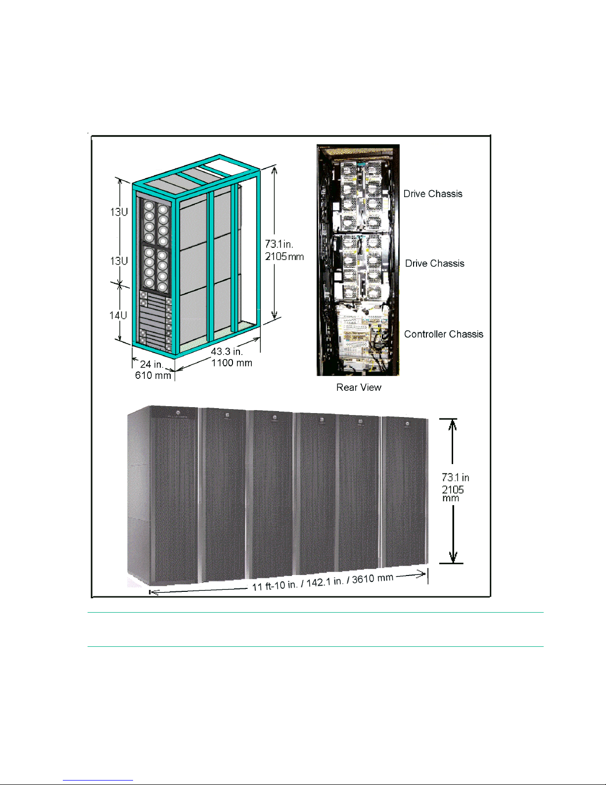
servers. A drive chassis consists of disks or SSD drives, power supplies, and the interface circuitry
connecting it to the controller chassis. The remaining racks (Rack-01, Rack-02, Rack-10 and
Rack-11) contain from one to three drive chassis.
The following sections provide descriptions and illustrations of the P9500 disk array and its
components.
Figure 1 P9500 disk array
NOTE: Each Rack is 600mm wide without side covers. Add 5mm to each end of entire assembly
for each side cover.
Controller chassis
The controller chassis (factory designation DKC) includes the logical components, memory, disk
drive interfaces, and host interfaces. It can be expanded with a high degree of granularity to a
system offering up to twice the number of processors, cache capacity, host interfaces and disk
storage capacity.
6 Introduction
Page 7
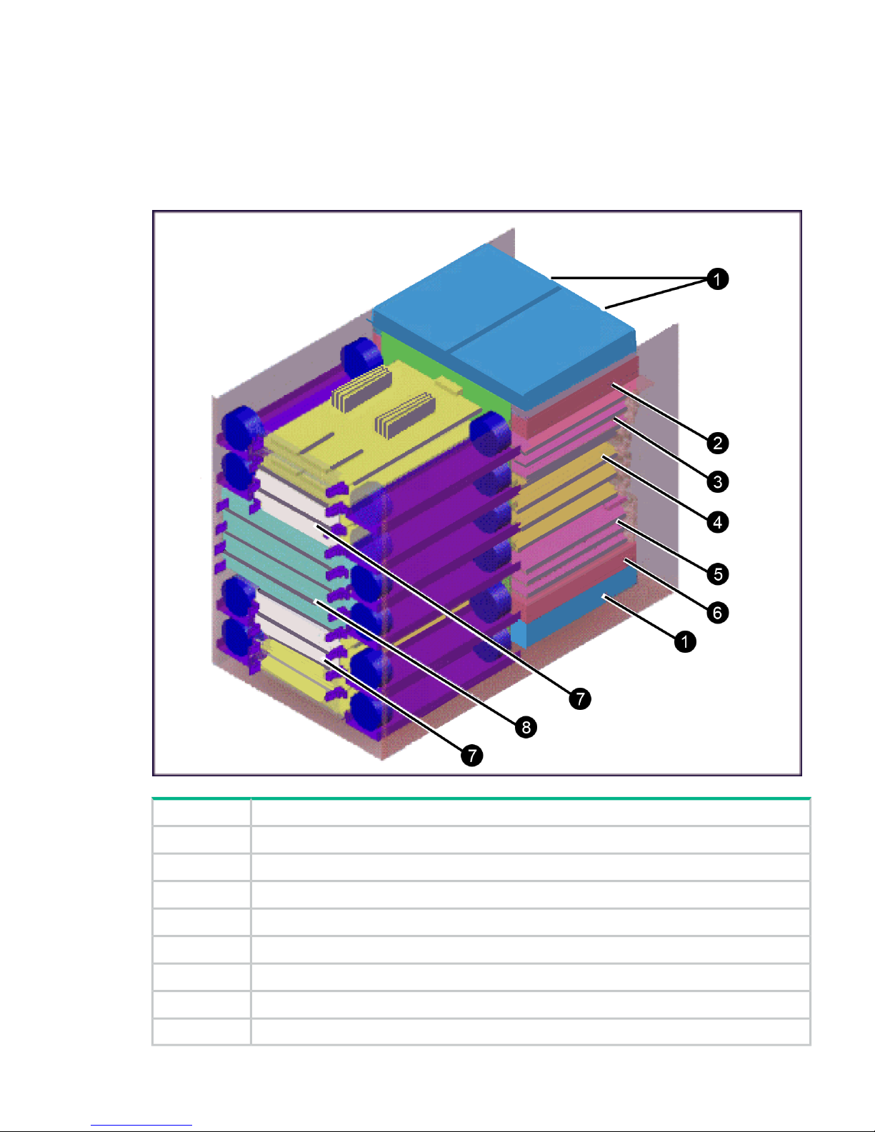
The controller chassis includes the following maximum number of components: two service
processors, 512 GB cache memory, four grid switches, four redundant power supplies, eight
channel adapters, four disk adapters, and ten dual fan assemblies. It is mounted at the bottom
of the rack because it is the heavier of the two units. If a system has two SVPs, both SVPs are
mounted in controller chassis #0.
The following illustration shows the locations of the components in the controller chassis.
Figure 2 Controller chassis
DescriptionItem
AC/DC: Power Supply 2 or 4 per controller1
Service Processor: One or two units in the #0 controller chassis2
CHA3
Grid switches4
CHA (up to 7) and DKA (up to 4)5
Service Processor: One or two units in the #0 controller chassis6
Cache: 2 to 8 cache boards in pairs (2, 4, 6, 8)7
P9500: 2 to 4 microprocessor boards8
Hardware overview 7
Page 8
Drive chassis
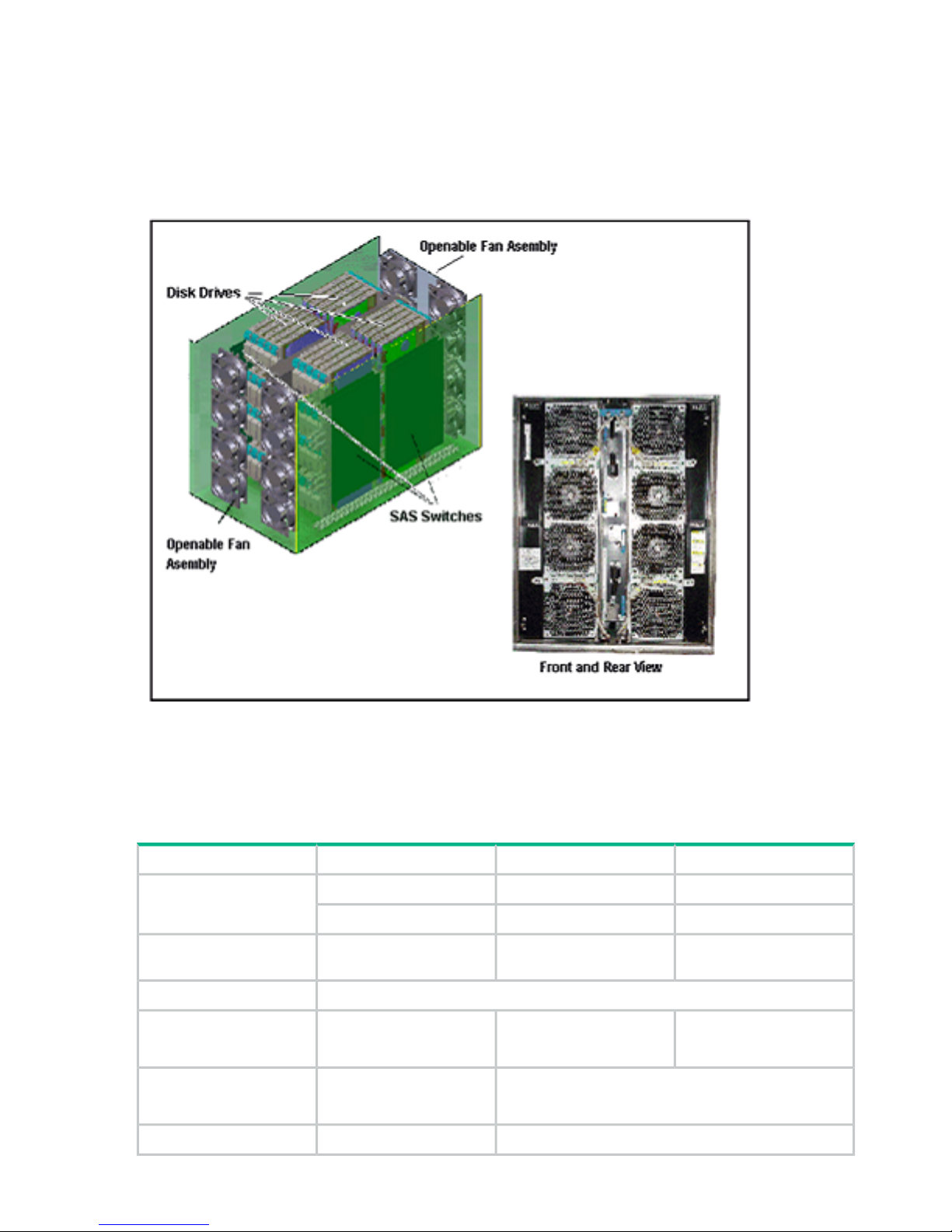
The drive chassis (factory designation DKU) consists of SAS switches, slots for 2 1/2 inch HDD
or SSD drives, and four 4 fan door assemblies that can be easily opened to allow access to the
drives. Each drive chassis can hold 128 2 1/2 inch HDD or SSD drives. The maximum number
of 2 1/2 inch drives in a P9500 system is 2048.
Figure 3 Disk Unit
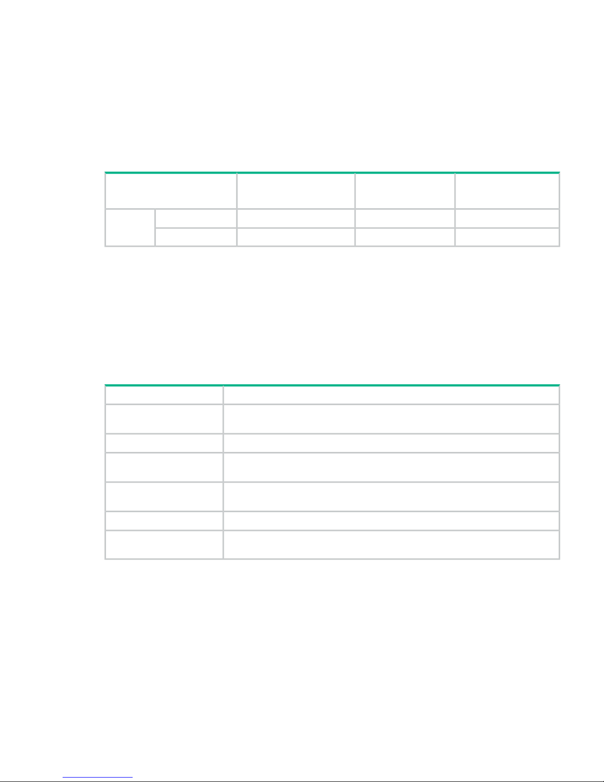
Specifications
The following tables provide general specifications of the P9500.
Table 1 P9500 specifications
Dual ModuleSingle ModuleSizeItem
589 TB294 TBInternalMaximum Capacity (based
on 900GB HDDs)
247 PB247 PBExternal
64k64k-Maximum number of
volumes
See Table 2 (page 9).Supported drives
Min 128 GBMin 64 GB.Cache memory capacity
Max 1024 GBMax 512 GB
Min 64 GB.Cache flash memory
capacity
Max 1028 GB
RAID1, RAID5, RAID6.RAID Level
8 Introduction
Page 9

Table 1 P9500 specifications (continued)
Dual ModuleSingle ModuleSizeItem
2D+2D, 4D+4DRAID1RAID GroupConfiguration
3D+1P, 7D+1PRAID5
6D+2PRAID6
Hierarchical Star NetArchitectureInternal Path
Cache Path = 128 GB/sMaximum Bandwidth
Control Path = 64 GB/s
64 (2WL*32)32 (2WL*6)SAS 6GBack-end Path
160/16,880 /16,8FC 2/4/8GNumber of ports per
installation unit
SAS/Dual PortController chassisDevice I/F
drive chassis
Interface
Max. 6 GBpsData transfer rate
256 (2.5 inch HDD)Maximum number
of HDD per SAS I/F
8 if drives installed4 if drives installedMaximum number of CHAs
12 if diskless6 if diskless
1/2/4 GBps Fibre Channel: 16MFS/16MFLMainframeChannel I/F
2/4/8 GBps Fibre Channel: 16MUS/16MUL
2/4/8 GBps Fibre Shortwave:Open systems
8UFC/16UFC
32 cores16 coresQuantityManagement Processor
Cores
6
1
6
1
CHAsMicro Processor Blade
configuration
2 / 80 or 2 / 42DKAs
Minimum/maximum
2 / 162 / 8Cache
4 / 82 / 4Switches /CSW
Notes:
1. All CHA configuration, no DKAs (diskless system).
Table 2 Drive specifications
Speed (RPM)Drive CapacitySizeDrive Type
15,000300 GB2 1/2 inchHDD (SAS)
10,000300, 600, and 900 GB
7,200500 GB and 1 TB
n/a200, 400, and 800 GB2 1/2 inchSSD (Flash)
Dual ModuleSingle ModuleDrive ChassisDrive Type
(6 rack system)(3 rack system)
Specifications 9
Page 10

Table 2 Drive specifications (continued)
Speed (RPM)Drive CapacitySizeDrive Type
20481024128HDD, 2 1/2 inch
256
2
128
2
128
1
SSD (Flash)
Notes.
1. SSD drives can be mounted all in one drive chassis or spread out among all of the chassis in the storage system.
2. Recommended maximum number.
10 Introduction
Page 11

2 Planning the Installation
NOTE: The GUI illustrations in this guide were created using a Windows computer with the
Internet Explorer browser. Actual windows may differ depending on the operating system and
browser used. GUI contents also vary with licensed program products, storage system models,
and firmware versions.
Responsibilities
The responsibilities for installation planning are shared by the customer and Hewlett Packard
Enterprise support. The required installation planning tasks must be scheduled and completed
to ensure successful and efficient installation of the P9500 disk array.
NOTE: The P9500 disk array must be installed by trained Hewlett Packard Enterprise personnel
or trained Hewlett Packard Enterprise Technical Support. The P9500 disk array is not a customer
installable product.
User Hewlett Packard Enterprise
You are responsible for performing the following tasks to prepare for installation of the P9500
disk array.
• Understand the applicable safety requirements associated with installing a P9500 disk array.
• Understand the installation requirements for the P9500 disk array. You can use the information
in this manual to determine the specific requirements for your installation. As needed, review
the P9500 user and reference guide to familiarize yourself with the components, features,
and functions of the P9500 disk array.
• Verify that the installation site meets all installation requirements. A checklist is included in
this section to help you with this task.
• Provide electrical hardware, including cables, connectors and receptacles that are required
to connect the P9500 disk array to site power.
• As needed, work with Hewlett Packard Enterprise support to create an installation plan.
Allow enough time to complete any changes to the plan, so your site is ready when the
equipment arrives.
Hewlett Packard Enterprise responsibilities
Hewlett Packard Enterprise support is responsible for completing the following tasks:
• Assist you as needed during the installation planning process for your specific site and
operational configuration
• Coordinate Hewlett Packard Enterprise resources to ensure a successful installation and
configuration of the P9500 disk array.
Responsibilities 11
Page 12

Installation planning checklist
The following checklist can help you ensure that your site meets all requirements needed to
install the P9500 disk array. You can make copies of this checklist for each installation you
perform and check each step after it has been performed. Keep the blank checklist in this
document for future use to verify that all installation requirements for the P9500 disk array are
met. Completing this checklist can help ensure smooth and efficient installation of the P9500
disk array.
Definition of terms
Equipment: The hardware delivered to the customer site that includes the P9500 disk array
components and rack(s).
Location: The specific location in the data center (area or “footprint” on the floor) where the
P9500 disk array will be installed.
User Information
Company
Address
Contact
Phone
Mobile
Email
Contact
Phone
Mobile
Email
Information
Contact
Phone
Mobile
Email
Contact
Phone
Mobile
Email
Notes
NoYesInstallation Planning Checklist
Safety Requirements
Is the data center equipped to protect the equipment from fire?
Is the data center free of hazards (for example, cables that obstruct access)?
Delivery Requirements
12 Planning the Installation
Page 13

NoYesInstallation Planning Checklist
Is the receiving area adequate for equipment delivery and unloading? (Can the area handle
crated equipment at least 90 in./2.29 m high?)
Are all doors, hallways, elevators, and ramps wide enough and high enough to allow the
equipment to be moved from the receiving area to the installation area?
Can the floors, elevators, and ramps support the weight of the equipment?
Storage Requirements
If the equipment will be stored after delivery and prior to installation, does the storage
location meet the environmental requirements for storing a P9500 disk array?
Facilities Requirements
Does the data center provide appropriate fire protection for computer equipment such as
P9500 disk arrays?
Does the data center have a raised floor?
Does the location meet the requirements for service clearance and cable routing (for example,
floor cutouts)?
Does the location meet the floor load rating requirements?
Power Requirements
Does the data center meet the AC input power requirements?
Does the data center meet the circuit breaker and plug requirements?
Is the customer supplied hardware such as connectors, receptacles, and cables ready for
the installation?
Environmental Requirements
Does the data center meet the operational temperature requirements for a P9500 disk
array?
Does the data center meet the operational humidity requirements for a P9500 disk array?
Does the data center meet the operational altitude requirements for a P9500 disk array?
Does the data center meet the air flow requirements for a P9500 disk array?
Does the data center provide adequate protection from ESD?
Does the data center provide adequate protection from electrical/radio frequency
interference?
Does the data center provide adequate protection from dust, pollution, and particulate
contamination?
Does the data center provide adequate acoustic insulation to operate the P9500 disk array?
Operational Requirements
Does the data center provide a LAN for Remote Web Console?
..hb-Is the infrastructure available for the default Internet based remote support solution?
Does the location meet the cable length requirements for the CHAs?
Does the location meet the requirements for attaching external storage?
Installation planning checklist 13
Page 14

System specifications and requirements
General safety guidelines
Observe the following general site guidelines:
• General Requirements: The data center must comply with all applicable safety regulations,
standards, and requirements for installing and operating industrial computer equipment
similar to a P9500 disk array.
• Fire protection: The data center must have an operational fire protection system appropriate
for use with computer and electrical equipment.
• Hazards: The data center must be free of hazards (for example, cables on the floor that
block access or that can cause people to trip).
• Equipment modifications: Do not make mechanical or electrical modifications to the
equipment. Hewlett Packard Enterprise is not responsible for regulatory compliance of a
modified Hewlett Packard Enterprise product.
• Earthquake Safety: To minimize personal injury in the event of an earthquake, securely
fasten the control and drive chassis to a rigid structure extending from the floor to the ceiling
or from the walls of the room in which the system is located.
• Cabling: Do not block walkways when routing cables. Do not place heavy materials on
cables. Do not place cables near any possible source of heat.
• Warning and safety labels: Safety warnings, cautions, and instructions in various languages
are attached to the P9500 disk array components. The safety warnings provide guidelines
to follow when working with any equipment. Hewlett Packard Enterprise recommends that
you read all warning labels on the hardware. If warning labels become dirty, damaged,
unreadable, or peel off, contact the Hewlett Packard Enterprise support center.
• Authorized personnel: Allow only qualified and authorized personnel (for example, a
certified electrician) to perform hazardous tasks.
Work safety guidelines
Observe the following site guidelines:
• Do not wear loose clothing that could get caught in the equipment or mounting hardware.
Fasten your tie or scarf and roll up your sleeves.
• Wear safety glasses when working under conditions that are hazardous to your eyes.
• Do not perform any action that creates a potential hazard to people or makes the equipment
or rack unsafe.
• Keep walkways clear of tools, power cables, and parts to prevent them from being stepped
on or causing people to trip and fall over them.
• Do not work on the equipment or disconnect cables during a thunderstorm, when wearing
a wool sweater or other heavy wool clothing, or when power is applied.
• Keep floors dry to prevent slips and falls.
• Do not use ungrounded power cables.
• Keep the area clear and dust free during and after installation.
• Do not block or cover equipment openings. Ensure that all equipment has adequate airflow.
Failure to follow these guidelines can cause overheating and affect the system reliability.
• The rack is equipped with casters so that you can move it short distances to position it for
final installation. Use enough personnel when moving a rack, especially on sloping loading
docks and ramps to a raised computer room floor. Move the cabinet slowly and deliberately,
14 Planning the Installation
Page 15

and make sure that the floor is free from foreign objects and cables that the cabinet could
roll over.
WARNING! To avoid injury, wear protective footwear when moving equipment.
Warning about moving parts
Even though customers do not install or maintain equipment, these guidelines are provided to
prevent possible injury when working with authorized service personnel. Observe the following
warning related to moving parts:
• Tuck in any loose clothing so that it cannot be caught by a moving or rotating part such as
a fan.
• Tie up long hair.
• Unless otherwise specifically instructed, do not supply power to any device that contains
rotating or moving parts that are not properly covered.
Electrical safety guidelines
Even though customers do not install or maintain equipment, these guidelines are provided to
prevent possible injury when working with authorized service personnel in the area where
equipment is installed. Observe the following electrical safety guidelines:
• Disconnect all power before installation, deinstallation, or moving equipment.
• Ensure that the voltage and frequency of your power source match the voltage and frequency
required by the system.
• All equipment should be properly grounded for proper operation and safety. To reduce the
risk of electric shock or damage to equipment, follow proper grounding procedures.
System specifications and requirements 15
Page 16
3 Installation requirements
General site requirements
The customer site must accommodate the delivery and movement of the equipment from the
receiving dock to the installation location in the data center.
Equipment clearances
Receiving area: The receiving dock, storage area, and receiving area must be large enough to
allow movement of and access to crated or packed equipment. The dimensions of a shipping
crate for a single rack are shown in the following table.
Table 3 P9500 shipping crate dimensions
DepthWidthHeightItem
53 in./1346 mm39 in./991 mm87 in./2210 mmShipping crate, single rack
NOTE: P9500 disk array racks are shipped in one of three standard packaging configurations:
• Environmental pack - This packaging configuration consists of stretch wrap over corner
protectors. Environmental pack is used for most shipments within the USA that are shipped
directly from the factory to the customer. Hewlett Packard Enterprise uses authorized carriers
with a dedicated fleet of trucks and specially trained personnel for Environmental pack
deliveries.
WARNING! P9500 rack shipments delivered in Environmental packs must not be forwarded
by carriers that are not authorized by Hewlett Packard Enterprise. Only Hewlett Packard
Enterprise authorized carriers can transport the P9500 racks in Environmental pack. Contact
Hewlett Packard Enterprise to arrange for Full Factory packaging when the P9500 rack will
be transported after initial delivery by Hewlett Packard Enterprise.
• Full Factory packaging - This packaging configuration consists of a pallet, wooden loading
ramp, inner packaging, and outer corrugated carton assembly. Full Factory packaging is
used for EMEA and for indirect ground shipments in USA and Canada.
WARNING! Full Factory packaging must be used any time a P9500 rack is transported
after initial delivery from the factory. Contact Hewlett Packard Enterprise to arrange for Full
Factory packaging.
• Full Factory packaging with wooden crate - This packaging configuration consists of full
packaging and encased in a wooden crate. Full Factory packaging with wooden crate is
used for air freight shipments from USA.
Other areas: The hallways, doorways, ramps, and elevators must be large enough to allow a
single unpacked rack to be moved to the installation location. Unless the distance between the
receiving dock and the data center is very long, P9500 disk arrays are typically unpacked in the
receiving area and the individual racks with pre-installed equipment are rolled on their casters
to the data center. The following table provides the dimensions of the P9500 disk array.
Table 4 P9500 single rack dimensions
DepthWidthHeightItem
45 in. (1145 mm) (includes
doors)
23.6 in. (600 mm) (add 0.4
in/10mm for side panels)
79 in. (2006 mm)Single rack
16 Installation requirements
Page 17
Equipment weight
The floors, elevators, and ramps must be able to support the weight of the delivered equipment
as it is moved to the installation location. Spreader plates may be required to distribute the load
and protect the floor as the equipment is moved from the receiving area to the installation location.
Consult the system bill of materials to establish the anticipated summary weights.
The weight of the equipment depends on the disk array configuration. The weight for a fully
configured disk array with 6 racks can reach 8560 pounds/3883 kilograms. The following table
provides weights of typical system configurations.
Table 5 Weight of typical P9500 system configurations
Dual ModuleSingle ModuleSingle RackDimension
(6 racks)(3 racks)
7500/34023750/17011120/508 (Diskless)Min (lbs/kg)System
Weight
8560/38834319/19591558/707Max (lbs/kg)
Storage requirements
If the equipment must be stored after delivery and prior to installation, the storage location must
meet the storage environmental requirements for the P9500 disk array. See Table 13 (page 26)
in this chapter for environmental storage requirements.
Data center requirements
The data center must meet the following facilities requirements:
Table 6 Data center requirements
DescriptionItem
The data center must provide appropriate power, air conditioning, cabling, and fire
protection.
General
The data center must provide adequate protection from electrostatic discharge (ESD).ESD
The data center must provide adequate protection from electrical/radio frequency
interference.
Electrical interference
The data center must provide adequate protection from dust, pollution, and particulate
contamination.
Contamination
The data center must provide adequate acoustic insulation for operating the system.Acoustics
This includes cables, connectors, and receptacles that must be available and ready
when the system is installed.
User-supplied hardware
Data communication requirements
Route data communication cables away from areas of high static electric fields created by power
transformers and heavy foot traffic. Use shielded data communication cables that meet approved
industrial standards to reduce the effects of external fields.
The P9500 frames support top access and bottom access for host cables. Routing the host cables
in a P9500 requires Hewlett Packard Enterprise support personnel to install. The data
communication infrastructure needed for the P9500 disk array is described in “Data communication
requirements” (page 18).
Data center requirements 17
Page 18

Table 7 Data communication requirements
Column HeadColumn Head
For the C-Track Internet connectivity, Hewlett Packard
Enterprise representatives will help you obtain and set
Internet connectivity infrastructure for C-Track
Internetbased remote support option.
up/order the necessary infrastructure, including your
choice of router configurations, a supported CMS
management server, and access to SMTP server
(optional) and DNS servers, in order to support reliable
file transfer and serve the overall objectives of the remote
support solution. An Hewlett Packard Enterprise
representative will configure C-Track , see “C-Track”
(page 18) or contact your Hewlett Packard Enterprise
representative.
Needed to connect the HPE system to an available
Ethernet port on the customer's LAN. To ensure network
A twisted pair (Cat 5) cable.
security, consult with an Hewlett Packard Enterprise
representative and your network administrator before
selecting the appropriate location of your LAN drop.
Needed to allow your staff and Hewlett Packard Enterprise
representatives to communicate inside and outside your
site.
A public voice phone line near the disk array.
C-Track
The C-Track remote support solution detects and reports events to the Hewlett Packard Enterprise
Support Service. C-Track transmits heartbeats, SIMs, and configuration information for remote
data collection and monitoring purposes. C-Track also enables the Support Service to remotely
diagnose issues and perform maintenance (if the customer allows the remote maintenance). The
C-Track solution offers Internet connectivity only. If you choose the Internet-based remote support
solution, additional infrastructure and site preparation are required. Additional preparation may
include server and router requirements, which you and Hewlett Packard Enterprise may be
responsible for implementing.
Insight Remote Support
Hewlett Packard Enterprise strongly recommends that you install HPE Insight Remote Support
software to complete the installation or upgrade of your product and to enable enhanced delivery
of your Hewlett Packard Enterprise Warranty, Care Pack Service or Hewlett Packard Enterprise
contractual support agreement. Insight Remote Support supplements your monitoring, 24x7 to
ensure maximum system availability by providing intelligent event diagnosis, and automatic,
secure submission of hardware event notifications to Hewlett Packard Enterprise, which will
initiate a fast and accurate resolution, based on your product’s service level. Notifications may
be sent to your authorized Hewlett Packard Enterprise Channel Partner for on-site service, if
configured and available in your country. The Insite Remote Support products available for the
P9500 disk arrays are described in Table 8 (page 18).
Table 8 XP9500 disk array remote support products
ApplicationDescriptionProduct
For customers that fully commit to use
Hewlett Packard Enterprise Remote
XP/XP9500 Remote Device Access
Support
AE241A
Support. It uses Insight Remote
Support for XP7 Remote Device
Monitoring utilizing LAN/Internet
connectivity and Remote Device
Access Support. This configuration is
required to meet the objectives of XP
disk array’s Internet connectivity with
18 Installation requirements
Page 19

Table 8 XP9500 disk array remote support products (continued)
ApplicationDescriptionProduct
Remote Device Access initiative and
prerequisites for Critical Support
contracts. Hewlett Packard Enterprise
recommends that the AE241A product
with Internet connectivity should be
utilized for all new XP7 installations, to
ensure the optimal support model and
highest TCE.
For customers that commit to utilize
Internet and Insight Remote Support
XP/XP9500 Remote Device Access
Support
AE242A
connectivity for XP9500 Remote
Device Monitoring but will not allow for
Remote Device Access to the XP9500
array from Hewlett Packard Enterprise
for proactive and critical support
processes. Without Remote Device
Access, Critical Support contract
prerequisites cannot be met.
For a customer with strict security
protocols specifically prohibits
HPE/XP9500 Mission Critical No LAN
Support
AE244A
inbound/outbound traffic to/from the
data center and thus will not allow
Remote Support connection by either
modem or LAN/internet connectivity;
but does have Mission Critical Services
with Customer Engineer onsite
included in the terms of the support
contract. Factory Authorization will be
required to order this product. Proof of
valid Customer Engineer on-site
Mission Critical support contract must
be provided for Factory Authorization
approval.
For a customer with strict security
protocols specifically prohibits
HPE/XP9500 No Mission Critical No
LAN Support
AE245A
inbound/outbound traffic to/from the
data center and thus will not allow
Remote Support connection by either
modem or LAN and does not have a
Mission Critical Services on-site
contract. The added costs of this
configuration only covers the additional
warranty support cost to Hewlett
Packard Enterprise during warranty
period. Other additional costs can also
be incurred for support contracts for
customers who do not have remote
support configured.
Details are available at: http://www.hpe.com/info/insightremotesupport
To download the software, go to Software Depot: http://www.hpe.com/support/softwaredepot
Select Insight Remote Support from the menu on the right.
Insight Remote Support 19
Page 20

System specifications and requirements
This section describes the physical characteristics of a P9500 disk array, including
• “Mechanical specifications” (page 20)
• “Electrical specifications” (page 22)
• “Environmental specifications” (page 26)
Mechanical specifications
The following table lists the mechanical specifications of the P9500 disk array.
Table 9 P9500 mechanical specifications
Six RacksFive RacksFour RacksThree RacksTwo RacksOne RackDimension
142 inches118.5 inches95 inches71.3 inches47.6 inches24.0 inchesWidth
(3610 mm)(3010 mm)(2410 mm)(1810 mm)(1210 mm)(610 mm)(includes 1 set of
side panels)
45 inches45 inches45 inches45 inches45 inches45 inchesDepth
(1145 mm)(1145 mm)(1145 mm)(1145 mm)(1145 mm)(1145 mm)(including doors)
79 inches79 inches79 inches79 inches79 inches79 inchesHeight
(2006 mm)(2006 mm)(2006 mm)(2006 mm)(2006 mm)(2006 mm)(including casters)
The following illustration shows an overview of a P9500 disk array.
20 Installation requirements
Page 21

Figure 4 P9500 disk array
NOTE: Each Rack is 600mm wide without side covers. Add 5mm to each end of entire assembly
for each side cover.
System specifications and requirements 21
Page 22

Figure 5 Example P9500 disk array configurations
Electrical specifications
“System heat and power specifications” (page 22) and “System components heat and power
specifications ” (page 22) list the heat and power specifications for the P9500 disk array and
components.
Table 10 System heat and power specifications
Full Array
(DKC-0 plus
DKU RackDKC Module-1DKC Module-0
Parameter
1, 2
DKC-1 plus DKU
x4)
33.15.455.425.87Max Power
consumption
(kVA)
Heat Dissipation
and Power
Consumption
Specifications
31.45.175.155.57Max Heat
dissipation (kW)
(Maximum
configuration)
107155176431757119012Max BTUs per
hour
27002444644284791Max Kcal per hour
1
Heat (KW, BTU, Kcal) and Power (kVA) values are for determining load for site planning. Actual heat generation
and power demand may be less.
2
Calculated values with drives at a typical I/O condition. (Random Read and Write, 50 IOPSs for HDD, 2500 IOPSs
for SSD, Data Length: 8Kbytes). These values may increase for future compatible drives.
Table 11 System components heat and power specifications
Power
Consumption
(kVA)
1
Heat Output
(kW)
1
P9500 Disk Array Component
Component Product
Number
0.640
4
0.600
4
Flash Module ChassisAV375A
0.018
3
0.017
3
Flash ModuleAV392A, AV393A
1.971.88Disk Array DKC Module-0 RackAV400A
1.931.83DKC Module-1 RackAV401A, AV401B
1.541.47DKU Disk Unit RackAV402A,AV402B
see note 5see note 5Base 2.5in Drive ChassisAV411B
22 Installation requirements
Page 23

Table 11 System components heat and power specifications (continued)
Power
Consumption
(kVA)
1
Heat Output
(kW)
1
P9500 Disk Array Component
Component Product
Number
0.6000.57Complete 2.5in Drive ChassisAV412B
0.1030.120Drive Chassis SAS Switch KitAV413A
0.0760.0728-port 2-8 Gbps FC CHAAV423A, AV423B
0.0760.07216-port 2-8 Gbps FC CHAAV424A, AV424B
0.1240.11816p 1-4 Gbps SW FICON CHAAV425A
0.1240.11816p 1-4 Gbps LW FICON CHAAV426A
0.0760.07216p 2-8 Gbps SW FICON CHAAV427A, AV427B
0.0760.07216p 2-8 Gbps LW FICON CHAAV428A
0.0760.072P9500 8-port 10 Gbps FCoE CHAAV429A
0.2000.19Processor BladeAV440A, AV440B
0.0100.010DKC Hub KitAV442A
0.0550.0522nd SVP High Reliability KitAV443A
0.0720.068Cache Memory AdapterAV444A
0.0200.01916GB Cache Memory ModuleAV447A, AV447B
0.0200.01932GB Cache Memory ModuleAV448A, AV448B
0.005
2
0.005
2
64GB Cache Backup Memory ModuleAV451A
0.005
2
0.005
2
128GB Cache Backup Memory ModuleAV452A
0.0840.08SAS DKA Drive AdapterAV455A
0.0740.07Express Switch AdapterAV458A
0.0074
3
0.0070
3
500GB 6G SAS 7.2K 2.5in DP HDDAV467A
0.0087
3
0.0082
3
1TB SAS 7.2K 2.5in DP HDDAV468A
0.0083
3
0.0079
3
300GB SAS 10K 2.5in DP HDDAV474A
0.0085
3
0.0080
3
600GB SAS 10K 2.5in DP HDDAV475A
0.0095
3
0.0090
3
900GB SAS 10K 2.5in DP HDDAV476A
0.0087
3
0.0083
3
1.2 TB SAS 10K 2.5in DP HDDAV477A
0.0084
3
0.0080
3
146GB SAS 15K 2.5in DP HDDAV482A
0.0090
3
0.0086
3
300GB SAS 15K 2.5in DP HDDAV483A
0.0134
3
0.0127
3
200GB SAS 2.5in DP SLC SSDAV490A
0.0024
3
0.0023
3
400GB SAS 2.5in DP SLC SSDAV491A
0.0028
3
0.0026
3
200GB SAS 2.5in DP MLC SSDAV492A
0.0028
3
0.0026
3
400GB SAS 2.5in DP MLC SSDAV493A
0.0071
3
0.0067
3
800GB SAS 2.5in DP MLC SSDAV494A
1
Heat (KW, BTU, Kcal) and Power (kVA) values are for determining rated load for site planning. Actual heat generation
and power demand may be less.
System specifications and requirements 23
Page 24

Table 11 System components heat and power specifications (continued)
Power
Consumption
(kVA)
1
Heat Output
(kW)
1
P9500 Disk Array Component
Component Product
Number
2
Power is consumed during the battery back-up time only.
3
Actual values at a typical I/O condition. (Random Read and Write, 50 IOPSs for HDD, 2500 IOPSs for SSD, Data
Length: 8 KB). These values may increase for future compatible drives.
4
Maximum values with all fans rotate at maximum.
5
AV411B Base 2.5 inch Drive Chassis does not include power supplies consequently demands zero (0) kVA and
generates no (0) kW heat.
NOTE: Site power can be connected to the PDUs at either the top or bottom of the racks.
Grounding
The site and equipment must meet all of the following three conditions of installation for grounding.
• An insulated grounding conductor that is identical in size and insulation material and thickness
to the grounded and ungrounded branch-circuit supply conductors. It must be green, with
or without yellow stripes, and must be installed as a part of the branch circuit that supplies
the unit or system.
• The grounding conductor mentioned above should be grounded to earth at the service
equipment or other acceptable building earth ground such as the building frame in the case
of a high rise steel-frame structure.
• The attachment-plug receptacles in the vicinity of the unit or system must include a ground
. The grounding conductors serving these receptacles must be connected to earth ground
at the service equipment or other acceptable building earth ground such as the building
frame in the case of a high-rise steel-frame structure.
Power connection
The AC power input for the P9500 disk array has a duplex PDU structure. This duplex structure
enables the entire rack to remain powered on if power is removed from one of the two power
distribution panels.
CAUTION: When installing a system, connect the AC cables between the PDUs and PDPs
correctly. Otherwise, a system failure can occur when one of the AC inputs is interrupted.
AC Power - PDU Options
The P9500 is configured for input power using separate rackmount PDU products. PDUs are
available for three phase or single phase power for NEMA and IEC compliance applications.
NOTE: When ordering systems, Hewlett Packard Enterprise does not allow mixtures of different
phase PDUs in a system (even though there are no technical issues). Only upgrade orders can
ship with difference phase PDUs in a system.
Table 12 P9500 AC PDU Options
Notes
Facility
receptacle
neededPlug Type
Branch circuit
requirements
per PDU
Number of
PDU per
Rack
1
Local Power
Product
Number
For customers
with, 200 - 220
NEMA
L15-30R
NEMA
L15-30P
200-220V, 3Ø,
4-wire, 30A
23 phase (4
wire)
AV404A
AV404AU
VAC, 3-Phase,
4-Wire Power
24 Installation requirements
Page 25

Table 12 P9500 AC PDU Options (continued)
Notes
Facility
receptacle
neededPlug Type
Branch circuit
requirements
per PDU
Number of
PDU per
Rack
1
Local Power
Product
Number
Distribution
System
For customers
with 380 - 415
IEC60309 4
pole, 5-wire,
IEC60309 4
pole, 5-wire
380-415V, 3Ø,
5-wire, 16A
23 phase (5
wire)
AV405A
AV405AU
VAC,380-415 VAC,
16A
380-415VAC,
16A Three-Phase,
5-Wire Wye
Power
Distribution
System
For customers
with single
NEMA L6-30RNEMA L6-30P200-240V, 1Ø,
3-wire, 30A
4single phase
NEMA
AV406A
AV406AU
phase power
and need
NEMA L6-30P
plug
For customers
with single
IEC60309 2
pole, 3-wire,
240VAC, 32A
IEC60309 2
pole, 3-wire,
240VAC, 32A
200-240V, 1Ø,
3-wire, 32A
4single phase
IEC
AV407A
AV407AU
phase power
and need
IEC60309 32A
plug
Notes
1. Each PDU has one fixed power cord with attached plug. Power cord is not removable.
NOTE: PDU models can be changed in the field by ordering the upgrade PDU model required.
Figure 6 P9500 AC Power Configuration Diagram
*1 (left): When connected correctly, one of the two PDUs can supply power to the DKC-DKU
rack.
System specifications and requirements 25
Page 26

*1 (right): When connected correctly, one of the four PDUs can supply power to the DKC-DKU
rack.
Environmental specifications
Table 13 (page 26) provides the environmental specifications and requirements for the P9500
disk array.
Table 13 P9500 environmental specifications
In StorageNot OperatingOperatingItem
-45 - 140ºF-18 - 109.4 ºF / (-10 to 43 ºC)60.8 - 80.9 ºFTemperature
(-25 to 60 ºC)-18 - 95 ºF / (-10 to 35 ºC)
8
(16 to 32 ºC)
5 to 95 %
2
8 to 90 %
2
20 to 80 %
2
Relative Humidity
84.2 ºF (29 ºC)80.6 ºF (27 ºC)78.8 ºF (26ºC)Max. Wet Bulb
68 ºF (20 ºC)50 ºF (10 ºC)50 ºF (10 ºC)Temperature
(Deviation per hour)
Sine Vibration:5 to 10 Hz: 2.5 mm10 to 300 HzVibration
4.9 m/s1, 5 min.10 to 70 Hz: 4.9 m/s
1
0.49 m/s
1
to 10Hz: 0.25 mm
At the resonant frequency with
the highest displacement found
between 3 to 100 Hz
3
70 to 99 Hz: 0.05 mm
99 to 300 Hz: 9.8 m/s
1
Random Vibration:
0.147 m2/s3
30 min, 5 to 100 Hz
4
--Up to 2.5
7
Earthquake resistance
(m/s2)
Horizontal:78.4 m/s1, 15 ms-Shock
Incline Impact 1.22 m/s
5
Vertical:
Rotational Edge 0.15 m
6
--60 to 3,000mAltitude
Notes:
1. Recommended temperature range is 21 to 24°C.
2. On shipping/storage condition, the product should be packed with factory packing.
3. The above specifications of vibration are applied to all three axes.
4. See ASTM D999-01 The Methods for Vibration Testing of Shipping Containers.
5. See ASTM D5277-92 Test Method for Performing Programmed Horizontal Impacts Using an Inclined Impact
Tester.
6. See ASTM D6055-96 Test Methods for Mechanical Handling of Unitized Loads and Large Shipping Cases and
Crates.
7. Time is 5 seconds or less in case of the testing with device resonance point (6 to 7Hz).
8. When flash modules are installed in the system.
Heat output and air flow
The following table lists the heat output and air flow requirements for the P9500 disk array.
Both the control chassis and the disk chassis contain front and rear fans to circulate air through
the chassis from front to back. Air flows in through the front bezel to the rear of the component
26 Installation requirements
Page 27

and exits through the perforations in the rear door. Either the front fans or the rear fans can cool
the chassis by themselves. The racks do not contain fans. Airflow is from front to back.
Table 14 Heat, power, and airflow
Air Flow (M3/min)Power Consumption (kVA)Heat Output (kW)Model Number
-0.640
6
0.600
6
AV375A P9500 Flash
Module Chassis
-0.018
3
0.017
3
AV392A P9500 1.6TB Flash
Module
-0.018
3
0.017
3
AV393A P9500 3.2TB Flash
Module
251.97
1
1.88
1
AV400A - P9500 Disk Array
DKC Module-0 Rack
-0.900.86AV400B - P9500 Disk Array
DKC Module-0 Rack
251.93
1
1.83
1
AV401A - P9500 DKC
Module-1 Rack
-0.500.48AV401B - P9500 DKC
Module-1 Rack
271.54
1
1.47
1
AV402A - P9500 DKU Disk
Unit Rack
-0.00.0AV402B - P9500 DKU Disk
Unit Rack
-see note 5see note 5AV411B P9500 Base 2.5in
Drive Chassis
-0.60.57AV412B P9500 Complete
2.5in Drive Chassis
6
-0.0760.120AV413A - P9500 Drive
Chassis SAS Switch Kit
-0.0760.072AV423A, AV423B - P9500
8-port 2-8 Gbps FC CHA
-0.0760.072AV424A, AV424B - P9500
16-port 2-8 Gbps FC CHA
-0.1240.118AV425A - P9500 16p 1-4
Gbps SW FICON CHA
-0.0760.118AV426A - P9500 16p 1-4
Gbps LW FICON CHA
-0.0760.072AV427A, AV427B - P9500
16p 2-8 Gbps SW FICON
CHA
-0.0760.072AV428A - P9500 16p 2-8
Gbps LW FICON CHA
-0.0760.072AV429A - P9500 8-port 10
Gbps FCoE CHA
-0.2000.19AV440A, AV440B - P9500
ProcessorBlade
-0.0100.010AV442A - P9500 DKC Hub
Kit
System specifications and requirements 27
Page 28

Table 14 Heat, power, and airflow (continued)
Air Flow (M3/min)Power Consumption (kVA)Heat Output (kW)Model Number
-0.0550.052AV443A - P9500 2nd SVP
High Reliability Kit
-0.0720.068AV444A - P9500 Cache
Memory Adapter
-0.0200.019AV447A, AV447B - P9500
16GB Cache Memory
Module
-0.0200.019AV448A, AV448B - P9500
32GB Cache Memory
Module
-0.005
2
0.005
2
AV451A - P9500 64GB
Cache Backup Memory
Module
-0.005
2
0.005
2
AV452A - P9500 128GB
Cache Backup Memory
Module
-0.0840.080AV455A - P9500 SAS DKA
Drive Adapter
-0.0740.070AV458A - P9500 Express
Switch Adapter
-0.0074
3
0.0070
3
AV467A - P9500 500GB 6G
SAS 7.2K 2.5in DP HDD
-0.0087
3
0.0082
3
AV468A - P9500 1TB SAS
7.2K 2.5in DP HDD
-0.0067
3
0.0063
3
AV474A - P9500 300GB
SAS 10K 2.5in DP HDD
-0.0085
3
0.0080
3
AV475A - P9500 600GB
SAS 10K 2.5in DP HDD
-0.0087
3
0.0083
3
AV477A - P9500 1.2TB 6G
SAS 10K 2.5in DP HDD
-0.0084
3
0.0080
3
AV482A - P9500 146GB
SAS 15K 2.5in DP HDD
-0.0090
3
0.0086
3
AV483A - P9500 300GB
SAS 15K 2.5in DP HDD
-0.0134
3
0.0127
3
AV490A - P9500 200GB
SAS 2.5in DP SLC SSD
-0.0024
3
0.0023
3
AV491A - P9500 400GB
SAS 2.5in DP SLC SSD
-0.0028
3
0.0026
3
AV492A - P9500 200GB
SAS 2.5in DP MLC SSD
-0.0028
3
0.0026
3
AV493A - P9500 400GB
SAS 2.5in DP MLC SSD
-0.0071
3
0.0067
3
AV494A - P9500 800GB
SAS 2.5in DP MLC SSD
Notes:
1
Maximum values in case the all fans rotate at maximum.
28 Installation requirements
Page 29

Table 14 Heat, power, and airflow (continued)
Air Flow (M3/min)Power Consumption (kVA)Heat Output (kW)Model Number
2
Power is consumed during the battery back-up time only.
3
Actual values at a typical I/O condition. (Random Read and Write, 50 IOPSs for HDD, 2500 IOPSs for SSD, Data
Length: 8Kbytes). These values may increase for future compatible drives.
5
AV411B Base 2.5in Drive Chassis does not include power supplies consequently demands zero (0) kVA and
generates no (0) kW heat. When AV459A/AU DKU Pow supplies are installed in an AV411B/BU, then the chassis
fans will demand same power and heat as AV412B/BU.
6
Maximum values with all fans rotate at maximum.
Equipment noise
The acoustic emission values [loudness in dB (A)] for the P9500 disk array disk array are:
• Front/rear = 65 dB (A)
• Both sides = 65 dB (A)
Service clearance, floor cutout, and floor load rating
This section describes the service clearance requirements for the P9500 disk array, based on
the floor load rating and the clearance and required floor cutouts for cabling. The figures and
tables that provide this information are listed in the following table.
Table 15 Service clearance and floor load ratings
Service Clearance and Floor Load Rating
SectionNumber of racks
“Single rack configuration” (page 29)1
“Two rack configuration (one DKC)” (page 31)2
“Two rack configuration (two DKC)” (page 33)2 (two DKC)
“Three rack configuration (left module)” (page 35)3 (left module)
“Three rack configuration (right module)” (page 36)3 (right module)
“Four rack configuration (left module)” (page 38)4 (left module)
“Four rack configuration (right module)” (page 39)4 (right module)
“Five rack configuration” (page 42)5
“Six rack configuration” (page 43)6
NOTE: For safe and efficient maintenance operations, clearance (c) should be made as large
as possible. Actual clearances for installation should be determined after consulting with the
site/facilities manager, as the clearances can vary, depending on building conditions. Although
all disk chassis come pre-installed, up to 1420 mm of clearance may be required at both front
and back for a disk chassis replacement.
The figures in this section are not drawn to scale.
Single rack configuration
The following figure and table show the service clearances and floor load rating for a single rack
configuration.
Service clearance, floor cutout, and floor load rating 29
Page 30

Figure 7 Service clearances for a single rack system
*1 Clearance (a+b) is based on the floor load rating and the clearance (c). Floor load rating and
required clearances are shown in Table 16 (page 30).
*2 Clearance (d) is required over 300mm to open the front door. In the case that the clearance
(d) is less tan the clearance (a), give priority to clearance (a).
*3 Clearance (e) is required over 200mm to open the rear door. If clearance (e) is less than
clearance (b), give priority to clearance (b).
*4 Dimensions in parentheses show allowable range of the front cutout dimensions. Basically,
position the floor cutout in the center of the rack. However, the position may be off center as long
as the cutout allows smooth entrance of an external cable (check the relation between the
positions of the cutout and the opening on the bottom plate of the rack) and is within the allowable
range.
Table 16 Floor load rating and required clearances for single rack configuration
Required Clearance (a+b) mFloor Load
Rating
Clearance (c) m
(kg/m2)
C=0.6C=0.6C=0.4C=0.2C=0
00010.500
000.10.10.2450
0.10.10.20.30.3400
30 Installation requirements
Page 31

Table 16 Floor load rating and required clearances for single rack configuration (continued)
Required Clearance (a+b) mFloor Load
Rating
(kg/m2)
Clearance (c) m
C=0.6C=0.6C=0.4C=0.2C=0
0.20.30.40.40.5350
0.40.60.70.80.9300
Notes:
1. Actual clearances for installation should be determined after consulting with construction specialist responsible
for installation building, as they could vary depending on the size/layout of the system and building conditions.
2. When various configurations of disk arrays are arranged in a row, clearance values based on the largest disk
array configuration should be used.
3. From the viewpoint of maintenance operations, it is suggested that Clearance (c) be made as large as possible.
Two rack configuration (one DKC)
The following figure and table shows the service clearances and floor load rating for a two-rack
configuration.
Service clearance, floor cutout, and floor load rating 31
Page 32

Figure 8 Service clearances for a two rack system (single DKC)
*1 Clearance (a+b) is based on the floor load rating and the clearance (c). Floor load rating and
required clearances are shown in Table 17 (page 32).
*2 Clearance (d) is required over 300mm to open the front door. In the case that the clearance
(d) is less tan the clearance (a), give priority to clearance (a).
Table 17 Floor load rating and required clearances for two rack configuration
Required Clearance (a+b) mFloor Load
Rating
Clearance (c) m
(kg/m2)
C=0.6C=0.6C=0.4C=0.2C=0
00000.1500
000.10.20.3450
32 Installation requirements
Page 33

Table 17 Floor load rating and required clearances for two rack configuration (continued)
Required Clearance (a+b) mFloor Load
Rating
(kg/m2)
Clearance (c) m
C=0.6C=0.6C=0.4C=0.2C=0
00.20.30.40.5400
0.30.50.60.80.9350
0.81.01.21.31.5300
Notes:
1. Actual clearances for installation should be determined after consulting with construction specialist responsible
for installation building, as they could vary depending on the size/layout of the system and building conditions.
2. When various configurations of disk arrays are arranged in a row, clearance values based on the largest disk
array configuration should be used.
3. From the viewpoint of maintenance operations, it is suggested that Clearance (c) be made as large as possible.
Two rack configuration (two DKC)
The following figure and table shows the service clearances and floor load rating for a two-rack
configuration with two DKCs installed.
Service clearance, floor cutout, and floor load rating 33
Page 34

Figure 9 Service clearances for a two rack system (two DKC)
*1 Clearance (a+b) is based on the floor load rating and the clearance (c). Floor load rating and
required clearances are shown in Table 18 (page 34).
*2 Clearance (d) is required over 300mm to open the front door. In the case that the clearance
(d) is less tan the clearance (a), give priority to clearance (a).
*3 Clearance (e) is required over 200mm to open the rear door. If clearance (e) is less than
clearance (b), give priority to clearance (b).
Table 18 Floor load rating and required clearances for a two rack configuration (two DKC)
Required Clearance (a+b) mFloor Load
Rating
Clearance (c) m
(kg/m2)
C=0.6C=0.6C=0.4C=0.2C=0
00000.1500
000.10.20.3450
00.20.30.40.5400
34 Installation requirements
Page 35

Table 18 Floor load rating and required clearances for a two rack configuration (two DKC)
(continued)
Required Clearance (a+b) mFloor Load
Rating
(kg/m2)
Clearance (c) m
C=0.6C=0.6C=0.4C=0.2C=0
0.30.50.60.80.9350
0.81.01.21.31.5300
Notes:
1. Actual clearances for installation should be determined after consulting with construction specialist responsible
for installation building, as they could vary depending on the size/layout of the system and building conditions.
2. When various configurations of disk arrays are arranged in a row, clearance values based on the largest disk
array configuration should be used.
3. From the viewpoint of maintenance operations, it is suggested that Clearance (c) be made as large as possible.
Three rack configuration (left module)
The following figure and table shows the service clearances and floor load rating for a three-rack
configuration.
Figure 10 Service clearances for a three rack system (left module)
Service clearance, floor cutout, and floor load rating 35
Page 36

*1 Clearance (a+b) is based on the floor load rating and the clearance (c). Floor load rating and
required clearances are shown in Table 19 (page 36).
*2 Clearance (d) is required over 300mm to open the front door. In the case that the clearance
(d) is less tan the clearance (a), give priority to clearance (a).
Table 19 Floor load rating and required clearances for a three rack configuration (left
module)
Required Clearance (a+b) mFloor Load
Rating
Clearance (c) m
(kg/m2)
C=0.6C=0.6C=0.4C=0.2C=0
00000.1500
000.10.20.4450
00.30.40.60.8400
0.40.70.91.11.3350
1.11.51.71.92.3300
Notes:
1. Actual clearances for installation should be determined after consulting with construction specialist responsible
for installation building, as they could vary depending on the size/layout of the system and building conditions.
2. When various configurations of disk arrays are arranged in a row, clearance values based on the largest disk
array configuration should be used.
3. From the viewpoint of maintenance operations, it is suggested that Clearance (c) be made as large as possible.
Three rack configuration (right module)
The following figure and table shows the service clearances and floor load rating for a three-rack
configuration (Setting Up DKC-RACK in the Right Configuration).
36 Installation requirements
Page 37

Figure 11 Service clearances for a three rack system (right module)
*1 Clearance (a+b) is based on the floor load rating and the clearance (c). Floor load rating and
required clearances are shown in Table 20 (page 37).
*2 Clearance (d) is required over 300mm to open the front door. In the case that the clearance
(d) is less tan the clearance (a), give priority to clearance (a).
*3 Clearance (e) is required over 200mm to open the rear door. If clearance (e) is less than
clearance (b), give priority to clearance (b).
Table 20 Floor load rating and required clearances for a three rack configuration (right
module)
Required Clearance (a+b) mFloor Load
Rating
Clearance (c) m
(kg/m2)
C=0.6C=0.6C=0.4C=0.2C=0
00000.1500
000.10.30.4450
0 .10.30.50.60.8400
0.50.81.01.21.4350
Service clearance, floor cutout, and floor load rating 37
Page 38

Table 20 Floor load rating and required clearances for a three rack configuration (right
module) (continued)
Required Clearance (a+b) mFloor Load
Rating
(kg/m2)
Clearance (c) m
C=0.6C=0.6C=0.4C=0.2C=0
1.21.51.82.02.3300
Notes:
1. Actual clearances for installation should be determined after consulting with construction specialist responsible
for installation building, as they could vary depending on the size/layout of the system and building conditions.
2. When various configurations of disk arrays are arranged in a row, clearance values based on the largest disk
array configuration should be used.
3. From the viewpoint of maintenance operations, it is suggested that Clearance (c) be made as large as possible.
Four rack configuration (left module)
The following figure and table shows the service clearances and floor load rating for a four-rack
configuration (Setting up DKC rack in the left configuration).
Figure 12 Service clearances for a four rack system (left module)
38 Installation requirements
Page 39

*1 Clearance (a+b) is based on the floor load rating and the clearance (c). Floor load rating and
required clearances are shown in Table 21 (page 39).
*2 Clearance (d) is required over 300mm to open the front door. In the case that the clearance
(d) is less tan the clearance (a), give priority to clearance (a).
Table 21 Floor load rating and required clearances for a four rack configuration (left
module)
Required Clearance (a+b) mFloor Load
Rating
Clearance (c) m
(kg/m2)
C=0.6C=0.6C=0.4C=0.2C=0
00000.1500
000.10.30.5450
0 .10.40.60.81.1400
0.61.01.21.51.8350
1.52.02.32.63.0300
Notes:
1. Actual clearances for installation should be determined after consulting with construction specialist responsible
for installation building, as they could vary depending on the size/layout of the system and building conditions.
2. When various configurations of disk arrays are arranged in a row, clearance values based on the largest disk
array configuration should be used.
3. From the viewpoint of maintenance operations, it is suggested that Clearance (c) be made as large as possible.
Four rack configuration (right module)
The following figure and table shows the service clearances and floor load rating for a four-rack
configuration (Setting Up DKC-RACK in the right Configuration).
Service clearance, floor cutout, and floor load rating 39
Page 40

Figure 13 Service clearances for a four rack system (right module)
*1 Clearance (a+b) is based on the floor load rating and the clearance (c). Floor load rating and
required clearances are shown in Table 22 (page 40).
*2 Clearance (d) is required over 300mm to open the front door. In the case that the clearance
(d) is less tan the clearance (a), give priority to clearance (a).
*3 Clearance (e) is required over 200mm to open the rear door. If clearance (e) is less than
clearance (b), give priority to clearance (b).
Table 22 Floor load rating and required clearances for a four rack configuration (right
module)
Required Clearance (a+b) mFloor Load
Rating
Clearance (c) m
(kg/m2)
C=0.6C=0.6C=0.4C=0.2C=0
00000.1500
000.10.30.5450
0 .10.40.60.81.1400
0.61.01.21.51.8350
40 Installation requirements
Page 41

Table 22 Floor load rating and required clearances for a four rack configuration (right
module) (continued)
Required Clearance (a+b) mFloor Load
Rating
(kg/m2)
Clearance (c) m
C=0.6C=0.6C=0.4C=0.2C=0
1.52.02.32.63.0300
Notes:
1. Actual clearances for installation should be determined after consulting with construction specialist responsible
for installation building, as they could vary depending on the size/layout of the system and building conditions.
2. When various configurations of disk arrays are arranged in a row, clearance values based on the largest disk
array configuration should be used.
3. From the viewpoint of maintenance operations, it is suggested that Clearance (c) be made as large as possible.
Service clearance, floor cutout, and floor load rating 41
Page 42

Five rack configuration
This following figure and table shows the service clearances and floor load rating for a five-rack
configuration.
Figure 14 Service clearances for a five rack system
*1 Clearance (a+b) is based on the floor load rating and the clearance (c). Floor load rating and
required clearances are shown in Table 23 (page 43).
*2 Clearance (d) is required over 300mm to open the front door. In the case that the clearance
(d) is less tan the clearance (a), give priority to clearance (a).
42 Installation requirements
Page 43

Table 23 Floor load rating and required clearances for a five rack configuration
Required Clearance (a+b) mFloor Load
Rating
Clearance (c) m
(kg/m2)
C=0.6C=0.6C=0.4C=0.2C=0
00000.1500
000.10.30.6450
0 .10.40.71.01.3400
0.71.21.51.82.2350
1.82.42.83.23.7300
Notes:
1. Actual clearances for installation should be determined after consulting with construction specialist responsible
for installation building, as they could vary depending on the size/layout of the system and building conditions.
2. When various configurations of disk arrays are arranged in a row, clearance values based on the largest disk
array configuration should be used.
3. From the viewpoint of maintenance operations, it is suggested that Clearance (c) be made as large as possible.
Six rack configuration
This following figure and table shows the service clearances and floor load rating for a six-rack
configuration.
Service clearance, floor cutout, and floor load rating 43
Page 44

Figure 15 Service clearances for a six rack system
*1 Clearance (a+b) is based on the floor load rating and the clearance (c). Floor load rating and
required clearances are shown in Table 24 (page 44).
*2 Clearance (d) is required over 300mm to open the front door. In the case that the clearance
(d) is less tan the clearance (a), give priority to clearance (a).
Table 24 Floor load rating and required clearances for a six rack configuration
Required Clearance (a+b) mFloor Load
Rating
Clearance (c) m
(kg/m2)
C=0.6C=0.6C=0.4C=0.2C=0
00000.1500
000.10.40.7450
44 Installation requirements
Page 45

Table 24 Floor load rating and required clearances for a six rack configuration (continued)
Required Clearance (a+b) mFloor Load
Rating
(kg/m2)
Clearance (c) m
C=0.6C=0.6C=0.4C=0.2C=0
0 .10.50.81.11.5400
0.91.41.82.22.6350
2.12.93.33.84.4300
Notes:
1. Actual clearances for installation should be determined after consulting with construction specialist responsible
for installation building, as they could vary depending on the size/layout of the system and building conditions.
2. When various configurations of disk arrays are arranged in a row, clearance values based on the largest disk
array configuration should be used.
3. From the viewpoint of maintenance operations, it is suggested that Clearance (c) be made as large as possible.
Operational requirements
The operational requirements for the P9500 include:
• LAN for Remote Web Console
Remote Web Console communicates with the P9500 disk array over a LAN to obtain system
configuration and status information and send user-requested commands to the disk array.
Remote Web Console serves as the integrated interface for all Resource Manager components.
• Cable length for channel adapters
Table 25 (page 45) lists the cable length requirements for the CHAs in the P9500 disk array.
Table 25 Maximum cable length (shortwave)
OM3(50/125ƒÝm laser
optimized multi-mode
fiber)
OM2(50/125ƒÝm
multi-modefiber)
OM1(62.5/125ƒÝm
multi-modefiber)
Data Transfer Rate
500 m500 m300 m100 MB/s
500 m300 m150 m200 MB/s
380 m150 m70 m400 MB/s
150 m50 m21 m800 MB/s
300 m82 m33 m10 GB/s (FCoE)
• External data storage
If you plan to attach external storage to the P9500 disk array, be sure to include the appropriate
power and space requirements in your planning.
Operational requirements 45
Page 46

4 Power On/Off procedures
Safety and environmental information
CAUTION: Before operating or working on the P9500 disk array, read the safety section in
theP9500 site preparation guide and the environmental information in ???.
Standby mode
When the disk array power cables are plugged into the PDUs and the PDU breakers are ON,
the disk array is in standby mode. When the disk array is in standby mode:
• The Basic Supply (BS) LED on the control panel is ON. This indicates that power is applied
to the power supplies.
• The READY LED is OFF. This indicates that the controller and drive chassis are not
operational.
• The fans in both the controller and drive chassis are running.
• The cache destage batteries are being charged.
• The disk array consumes significantly less power than it does in operating mode. For example,
a disk array that draws 100 amps while operating draws only about 70 amps in standby
mode (see “Electrical specifications” (page 55)) for power consumption specifications.
To put the disk array into standby mode from the OFF condition:
1. Ensure that power is available to the AC input boxes and PDUs in all racks in which the
P9500 disk array is installed.
2. Turn all PDU power switches/breakers ON.
To put the disk array into standby mode from a power on condition, complete the power off
procedures in this chapter. See “Power Off procedures” (page 47).
To completely power down the disk array, complete the power off procedures in this chapter,
then turn off all PDU circuit breakers.
CAUTION: Make certain that the disk array is powered off normally and in standby mode
before turning off the PDU circuit breakers. Otherwise, turning off the PDU circuit breakers can
leave the disk array in an abnormal condition.
Power On/Off procedures
This section provides general information about power on/off procedures for the P9500 disk
array. If needed, consult Hewlett Packard Enterprise Technical Support for assistance.
Power On procedures
CAUTION: Only a trained Hewlett Packard Enterprise support representative can restore
power to the disk array.
Prerequisites
• Ensure that the disk array is in standby mode. See “Standby mode” (page 46).
NOTE: The control panel includes a safety feature to prevent the storage system power from
accidentally being turned on or off. The PS power ON/OFF switch does not work unless the
ENABLE switch is moved to and held in the ENABLE position while the power switch is moved
to the ON or OFF positions.
46 Power On/Off procedures
Page 47

Follow this procedure exactly when powering the disk array on. Refer to the illustration of the
control panel as needed.
1. On the control panel, check the amber BS LED and make sure it is lit. It indicates that the
disk array is in standby mode.
2. In the PS area on the control panel, move the Enable switch to the ENABLED position. Hold
the switch in the Enabled position and move the PS ON switch to the ON position. Then
release the ENABLE switch.
3. Wait for the disk array to complete its power-on self-test and boot-up processes. Depending
on the disk array configuration, this may take several minutes.
4. When the Ready LED is ON, the disk array boot up operations are complete and the disk
array is ready for use.
NOTE: If the Alarm LED is also on, or if the Ready LED is not ON after 20 minutes, contact
Hewlett Packard Enterprise Technical Support. The disk array generates a SIM that provides
the status of the battery charge (see “Cache destage batteries” (page 48)).
Power Off procedures
CAUTION: Only a trained Hewlett Packard Enterprise support representative can shut down
and power off the disk array. Do not attempt to power down the disk array other than during an
emergency.
Prerequisites:
• Ensure that all software specific shutdown procedures have been completed. See the
applicable user manuals for details.
• Ensure that all I/O activity to the disk array has stopped. You can vary paths offline and/or
shut down the attached hosts.
Follow this procedure exactly when powering the disk array off.
1. In the PS area on the power panel, move the Enable switch to the Enabled position. Hold
the switch in the Enabled position and press the PS OFF switch on the Operator Panel.
2. Wait for the disk array to complete its shutdown routines. Depending on the disk array
configuration and certain MODE settings, it can take up to 20 minutes for the disk array to
copy data from cache to the disk drives and for the disk drives to spin down.
NOTE: If the Ready and PS LEDs do not turn OFF after 20 minutes, contact Hewlett
Packard Enterprise Technical Support.
Battery backup operations
The P9500 is designed so that it cannot lose data or configuration information if the power fails.
The battery system is designed to provide enough power to completely destage all data in the
cache if two consecutive power failures occur and the batteries are fully charged. If the batteries
do not contain enough charge to provide sufficient time to destage the cache when a power
failure occurs, the cache operates in write through mode. This synchronously writes to HDDs to
Battery backup operations 47
Page 48

prevent slow data throughout in the cache. When the battery charge is 50% or more, the cache
write protect mode operates normally.
When a power failure occurs and continues for 20 milliseconds or less, the disk array continues
normal operation. If the power failure exceeds 20 milliseconds, the disk array uses power from
the batteries to back up the cache memory data and disk array configuration data to the cache
flash memory on each cache board. This continues for up to ten minutes. The flash memory
does not require power to retain the data. The following illustration shows the timing in the event
of a power failure.
Figure 16 Battery backup operations
DescriptionItem
Power failure occurs
The storage system continues to operate for 20 milliseconds and detects the power failure.
The cache memory data and the storage system configuration are backed up to the cache flash
memory on the cache boards. The backup continues even if power is restored during the backup.
Unrestricted data backup. Data is continuously backed up to the cache flash memory.
Cache destage batteries
The environmentally friendly nickel hydride cache destage batteries are used to save disk array
configuration and data in the cache in the event of a power failure. The batteries are located on
the cache memory boards and are fully charged at the distribution center where the disk array
is assembled and tested. Before the system is shipped to a customer site, the batteries are
disconnected by a jumper on the cache board. This prevents them from discharging during
shipping and storage until the system is installed. At that time, Hewlett Packard Enterprise
Technical Support representative connects the batteries.
NOTE: The disk array generates a SIM when the cache destage batteries are not connected.
Battery life
The batteries have a lifespan of three years, and will hold the charge when connected. When
the batteries are connected and power is on, they are charged continuously. This occurs during
both normal system operation and while the system is in standby mode.
When the batteries are connected and the power is off, the batteries slowly discharge. They will
have a charge of less than 50% after two weeks without power. When fully discharged, the
batteries must be connected to power for three hours to fully recharge.
48 Power On/Off procedures
Page 49

NOTE: The disk array generates a SIM when the cache destage batteries are not charged to
at least 50%. The LEDs on the front panel of the cache boards also show the status of the
batteries.
Long term array storage
While connected, the cache destage batteries will completely discharge in two to three weeks
without power applied. If you do not use a P9500 for two weeks or more, contact Hewlett Packard
Enterprise Technical Support to move the batteries to a disk array that is being used, or turn the
disk array on to standby mode for at least 3 hours once every two weeks.
If you store the system for more than two weeks and do not disconnect the cache destage
batteries, when you restart the system, the batteries will need to charge for at least 90 minutes
before the cache will be protected. To prevent the batteries from discharging during long term
storage, contact Hewlett Packard Enterprise Technical Support and ask them to disconnect the
battery jumpers on the cache boards.
Battery backup operations 49
Page 50

5 Technical Specifications
This chapter describes the physical, electrical, and operating specifications of an P9500 disk
array.
Mechanical specifications
The following table lists the mechanical specifications of the P9500 disk array.
Table 26 P9500 mechanical specifications
Dual ModuleSingle ModuleSingle RackDimension
(6 racks)(3 racks)
142 / 361071.3 / 181024.0 / 610Width (inches / mm)
45 / 114545 / 114545 / 1145Depth (inches / mm)
79 / 200679 / 200679 / 2006Height (inches / mm)
7500 / 34023750 / 17011120 / 508 (Diskless)Min (lbs / kg)System
Weight
8560 / 38834319 / 19591558 / 707Max (lbs / kg)
Rack Weight is included in system weight292.6 / 133(lbs / kg)Rack
Weight
Electrical specifications
The P9500 supports single-phase and three-phase power. Power consumption and heat
dissipation is independent of input power.
“System heat and power specifications” (page 55) lists system heat and power specifications.
“System components heat and power specifications ” (page 56) lists component heat and power
specifications.
“AC power - PDU options” (page 57) lists the PDU specifications for both single phase and three
phase power.
System heat and power specifications
Table 27 System heat and power specifications
Full Array
(DKC-0 plus
DKU RackDKC Module-1DKC Module-0
Parameter
1, 2
DKC-1 plus DKU
x4)
33.15.455.425.87Max Power
consumption
(kVA)
Heat Dissipation
and Power
Consumption
Specifications
31.45.175.155.57Max Heat
dissipation (kW)
(Maximum
configuration)
107155176431757119012Max BTUs per
hour
27002444644284791Max Kcal per hour
1
Heat (KW, BTU, Kcal) and Power (kVA) values are for determining load for site planning. Actual heat generation
and power demand may be less.
2
Calculated values with drives at a typical I/O condition. (Random Read and Write, 50 IOPSs for HDD, 2500 IOPSs
for SSD, Data Length: 8Kbytes). These values may increase for future compatible drives.
50 Technical Specifications
Page 51

System components heat and power specifications
Table 28 System components heat and power specifications
Power
Consumption
(kVA)
1
Heat Output
(kW)
1
P9500 Disk Array Component
Component Product
Number
0.640
4
0.600
4
Flash Module ChassisAV375A
0.018
3
0.017
3
Flash ModuleAV392A, AV393A
1.971.88Disk Array DKC Module-0 RackAV400A
1.931.83DKC Module-1 RackAV401A, AV401B
1.541.47DKU Disk Unit RackAV402A,AV402B
see note 5see note 5Base 2.5in Drive ChassisAV411B
0.6000.57Complete 2.5in Drive ChassisAV412B
0.1030.120Drive Chassis SAS Switch KitAV413A
0.0760.0728-port 2-8 Gbps FC CHAAV423A, AV423B
0.0760.07216-port 2-8 Gbps FC CHAAV424A, AV424B
0.1240.11816p 1-4 Gbps SW FICON CHAAV425A
0.1240.11816p 1-4 Gbps LW FICON CHAAV426A
0.0760.07216p 2-8 Gbps SW FICON CHAAV427A, AV427B
0.0760.07216p 2-8 Gbps LW FICON CHAAV428A
0.0760.072P9500 8-port 10 Gbps FCoE CHAAV429A
0.2000.19Processor BladeAV440A, AV440B
0.0100.010DKC Hub KitAV442A
0.0550.0522nd SVP High Reliability KitAV443A
0.0720.068Cache Memory AdapterAV444A
0.0200.01916GB Cache Memory ModuleAV447A, AV447B
0.0200.01932GB Cache Memory ModuleAV448A, AV448B
0.005
2
0.005
2
64GB Cache Backup Memory ModuleAV451A
0.005
2
0.005
2
128GB Cache Backup Memory ModuleAV452A
0.0840.08SAS DKA Drive AdapterAV455A
0.0740.07Express Switch AdapterAV458A
0.0074
3
0.0070
3
500GB 6G SAS 7.2K 2.5in DP HDDAV467A
0.0087
3
0.0082
3
1TB SAS 7.2K 2.5in DP HDDAV468A
0.0083
3
0.0079
3
300GB SAS 10K 2.5in DP HDDAV474A
0.0085
3
0.0080
3
600GB SAS 10K 2.5in DP HDDAV475A
0.0095
3
0.0090
3
900GB SAS 10K 2.5in DP HDDAV476A
0.0087
3
0.0083
3
1.2 TB SAS 10K 2.5in DP HDDAV477A
0.0084
3
0.0080
3
146GB SAS 15K 2.5in DP HDDAV482A
System components heat and power specifications 51
Page 52

Table 28 System components heat and power specifications (continued)
Power
Consumption
(kVA)
1
Heat Output
(kW)
1
P9500 Disk Array Component
Component Product
Number
0.0090
3
0.0086
3
300GB SAS 15K 2.5in DP HDDAV483A
0.0134
3
0.0127
3
200GB SAS 2.5in DP SLC SSDAV490A
0.0024
3
0.0023
3
400GB SAS 2.5in DP SLC SSDAV491A
0.0028
3
0.0026
3
200GB SAS 2.5in DP MLC SSDAV492A
0.0028
3
0.0026
3
400GB SAS 2.5in DP MLC SSDAV493A
0.0071
3
0.0067
3
800GB SAS 2.5in DP MLC SSDAV494A
1
Heat (KW, BTU, Kcal) and Power (kVA) values are for determining rated load for site planning. Actual heat generation
and power demand may be less.
2
Power is consumed during the battery back-up time only.
3
Actual values at a typical I/O condition. (Random Read and Write, 50 IOPSs for HDD, 2500 IOPSs for SSD, Data
Length: 8Kbytes). These values may increase for future compatible drives.
4
Maximum values with all fans rotate at maximum.
5
AV411B Base 2.5in Drive Chassis does not include power supplies consequenly demands zero (0) kVA and
geneates no (0) kW heat.
AC power - PDU options
The P9500 is configured for input power using separate rackmount PDU products. PDUs are
available for three phase or single phase power for NEMA and IEC compliance applications.
Table 29 P9500 AC PDU options
Notes
Facility
receptacle
neededPlug Type
Branch circuit
requirements
per PDU
Number of
PDU per
Rack
1
Local Power
Product
Number
For customers
with, 208 - 240
NEMA
L15-30R
NEMA
L15-30P
208-240V, 3Ø,
4-wire, 30A
23 phase (4
wire)
AV404A
AV404AU
VAC, 3-Phase,
4-Wire Power
Distribution
System
For customers
with 380 - 415
IEC60309 4
pole, 5-wire,
IEC60309 4
pole, 5-wire
380-415V, 3Ø,
5-wire, 16A
23 phase (5
wire)
AV405A
AV405AU
VAC,380-415 VAC,
16A
380-415VAC,
16A
Category D
Breaker Three-Phase,
5-Wire Wye
Power
Distribution
System
For customers
with single
NEMA L6-30RNEMA L6-30P200-240V, 1Ø,
3-wire, 30A
4single phase
NEMA
AV406A
AV406AU
phase power
and need
NEMA L6-30P
plug
For customers
with single
IEC60309 2
pole, 3-wire,
240VAC, 32A
IEC60309 2
pole, 3-wire,
240VAC, 32A
200-240V, 1Ø,
3-wire, 32A
Category D
Breaker
4single phase
IEC
AV407A
AV407AU
phase power
and need
52 Technical Specifications
Page 53

Table 29 P9500 AC PDU options (continued)
Notes
Facility
receptacle
neededPlug Type
Branch circuit
requirements
per PDU
Number of
PDU per
Rack
1
Local Power
Product
Number
IEC60309 32A
plug
Notes:
1. Each PDU has one fixed power cord with attached plug. Power cord is not removable.
NOTE: PDU models can be changed in the field using offline maintenance procedures.
NOTE: When ordering systems, Hewlett Packard Enterprise does not allow mixtures of different
phase PDUs in a system (even though there are no technical issues). Only upgrade orders can
ship with difference phase PDUs in a system.
Figure 17 P9500 AC power configuration diagram
*1 (left): When connected correctly, one of the two PDUs can supply power to the DKC-DKU
rack.
*1 (right): When connected correctly, one of the four PDUs can supply power to the DKC-DKU
rack.
Environmental specifications
The following table lists the environmental specifications of the P9500 storage system.
Table 30 P9500 environmental specifications
In StorageNot OperatingOperatingItem
-45 - 140-18 - 109.4 / -10 to 4360.8 - 80.9 /Temperature
-25 to 60-18 to 95 / -10 to 35
8
16 to 32(ºF / ºC)
5 to 958 to 9020 to 80Relative Humidity
(%)
2
Environmental specifications 53
Page 54

Table 30 P9500 environmental specifications (continued)
In StorageNot OperatingOperatingItem
84.2 / 2980.6 / 2778.8 / 26Max. Wet Bulb
(ºF / ºC)
68 / 2050 / 1050 / 10Temperature
Deviation
per hour)
(ºF / ºC)
Sine Vibration:5 to 10 Hz: 2.5 mm10 to 300 HzVibration
4.9 m/s1, 5 min.10 to 70 Hz: 4.9 m/s
1
0.49 m/s
1
to 10Hz: 0.25 mm
At the resonant frequency with
the highest displacement found
between 3 to 100 Hz
3
70 to 99 Hz: 0.05 mm
99 to 300 Hz: 9.8 m/s
1
Random Vibration:
0.147 m2/s3
30 min, 5 to 100 Hz
4
--Up to 2.5
7
Earthquake
resistance (m/s2)
Horizontal:78.4 m/s1, 15 ms-Shock
Incline Impact 1.22 m/s
5
Vertical:
Rotational Edge 0.15 m
6
--60 m to 3,000 mAltitude
Notes:
1. Recommended temperature range is 21 to 24°C
2. On shipping/storage condition, the product should be packed with factory packing
3. The above specifications of vibration are applied to all three axes
4. See ASTM D999-01 The Methods for Vibration Testing of Shipping Containers.
5. See ASTM D5277-92 Test Method for Performing Programmed Horizontal Impacts Using an Inclined Impact
Tester.
6. See ASTM D6055-96 Test Methods for Mechanical Handling of Unitized Loads and Large Shipping Cases and
Crates.
7. Time is 5 seconds or less in case of the testing with device resonance point (6 to 7Hz).
8. When flash modules are installed in the system.
54 Technical Specifications
Page 55

A Technical Specifications
Mechanical specifications
The following table lists the mechanical specifications of the P9500 disk array.
Table 31 P9500 mechanical specifications
Dual ModuleSingle ModuleSingle RackDimension
(6 racks)(3 racks)
142 / 361071.3 / 181024.0 / 610Width (inches / mm)
45 / 114545 / 114545 / 1145Depth (inches / mm)
79 / 200679 / 200679 / 2006Height (inches / mm)
7500 / 34023750 / 17011120 / 508 (Diskless)Min (lbs / kg)System
Weight
8560 / 38834319 / 19591558 / 707Max (lbs / kg)
Rack Weight is included in system weight292.6 / 133(lbs / kg)Rack
Weight
Electrical specifications
The P9500 supports single-phase and three-phase power. Power consumption and heat
dissipation is independent of input power.
“System heat and power specifications” (page 55) lists system heat and power specifications.
“System components heat and power specifications ” (page 56) lists component heat and power
specifications.
“AC power - PDU options” (page 57) lists the PDU specifications for both single phase and three
phase power.
System heat and power specifications
Table 32 System heat and power specifications
Full Array
(DKC-0 plus
DKU RackDKC Module-1DKC Module-0
Parameter
1, 2
DKC-1 plus DKU
x4)
33.15.455.425.87Max Power
consumption
(kVA)
Heat Dissipation
and Power
Consumption
Specifications
31.45.175.155.57Max Heat
dissipation (kW)
(Maximum
configuration)
107155176431757119012Max BTUs per
hour
27002444644284791Max Kcal per hour
1
Heat (KW, BTU, Kcal) and Power (kVA) values are for determining load for site planning. Actual heat generation
and power demand may be less.
2
Calculated values with drives at a typical I/O condition. (Random Read and Write, 50 IOPSs for HDD, 2500 IOPSs
for SSD, Data Length: 8Kbytes). These values may increase for future compatible drives.
Mechanical specifications 55
Page 56

System components heat and power specifications
Table 33 System components heat and power specifications
Power
Consumption
(kVA)
1
Heat Output
(kW)
1
P9500 Disk Array Component
Component Product
Number
0.640
4
0.600
4
Flash Module ChassisAV375A
0.018
3
0.017
3
Flash ModuleAV392A, AV393A
1.971.88Disk Array DKC Module-0 RackAV400A
1.931.83DKC Module-1 RackAV401A, AV401B
1.541.47DKU Disk Unit RackAV402A,AV402B
see note 5see note 5Base 2.5in Drive ChassisAV411B
0.6000.57Complete 2.5in Drive ChassisAV412B
0.1030.120Drive Chassis SAS Switch KitAV413A
0.0760.0728-port 2-8 Gbps FC CHAAV423A, AV423B
0.0760.07216-port 2-8 Gbps FC CHAAV424A, AV424B
0.1240.11816p 1-4 Gbps SW FICON CHAAV425A
0.1240.11816p 1-4 Gbps LW FICON CHAAV426A
0.0760.07216p 2-8 Gbps SW FICON CHAAV427A, AV427B
0.0760.07216p 2-8 Gbps LW FICON CHAAV428A
0.0760.072P9500 8-port 10 Gbps FCoE CHAAV429A
0.2000.19Processor BladeAV440A, AV440B
0.0100.010DKC Hub KitAV442A
0.0550.0522nd SVP High Reliability KitAV443A
0.0720.068Cache Memory AdapterAV444A
0.0200.01916GB Cache Memory ModuleAV447A, AV447B
0.0200.01932GB Cache Memory ModuleAV448A, AV448B
0.005
2
0.005
2
64GB Cache Backup Memory ModuleAV451A
0.005
2
0.005
2
128GB Cache Backup Memory ModuleAV452A
0.0840.08SAS DKA Drive AdapterAV455A
0.0740.07Express Switch AdapterAV458A
0.0074
3
0.0070
3
500GB 6G SAS 7.2K 2.5in DP HDDAV467A
0.0087
3
0.0082
3
1TB SAS 7.2K 2.5in DP HDDAV468A
0.0083
3
0.0079
3
300GB SAS 10K 2.5in DP HDDAV474A
0.0085
3
0.0080
3
600GB SAS 10K 2.5in DP HDDAV475A
0.0095
3
0.0090
3
900GB SAS 10K 2.5in DP HDDAV476A
0.0087
3
0.0083
3
1.2 TB SAS 10K 2.5in DP HDDAV477A
0.0084
3
0.0080
3
146GB SAS 15K 2.5in DP HDDAV482A
56 Technical Specifications
Page 57

Table 33 System components heat and power specifications (continued)
Power
Consumption
(kVA)
1
Heat Output
(kW)
1
P9500 Disk Array Component
Component Product
Number
0.0090
3
0.0086
3
300GB SAS 15K 2.5in DP HDDAV483A
0.0134
3
0.0127
3
200GB SAS 2.5in DP SLC SSDAV490A
0.0024
3
0.0023
3
400GB SAS 2.5in DP SLC SSDAV491A
0.0028
3
0.0026
3
200GB SAS 2.5in DP MLC SSDAV492A
0.0028
3
0.0026
3
400GB SAS 2.5in DP MLC SSDAV493A
0.0071
3
0.0067
3
800GB SAS 2.5in DP MLC SSDAV494A
1
Heat (KW, BTU, Kcal) and Power (kVA) values are for determining rated load for site planning. Actual heat generation
and power demand may be less.
2
Power is consumed during the battery back-up time only.
3
Actual values at a typical I/O condition. (Random Read and Write, 50 IOPSs for HDD, 2500 IOPSs for SSD, Data
Length: 8Kbytes). These values may increase for future compatible drives.
4
Maximum values with all fans rotate at maximum.
5
AV411B Base 2.5in Drive Chassis does not include power supplies consequenly demands zero (0) kVA and
geneates no (0) kW heat.
AC power - PDU options
The P9500 is configured for input power using separate rackmount PDU products. PDUs are
available for three phase or single phase power for NEMA and IEC compliance applications.
Table 34 P9500 AC PDU options
Notes
Facility
receptacle
neededPlug Type
Branch circuit
requirements
per PDU
Number of
PDU per
Rack
1
Local Power
Product
Number
For customers
with, 208 - 240
NEMA
L15-30R
NEMA
L15-30P
208-240V, 3Ø,
4-wire, 30A
23 phase (4
wire)
AV404A
AV404AU
VAC, 3-Phase,
4-Wire Power
Distribution
System
For customers
with 380 - 415
IEC60309 4
pole, 5-wire,
IEC60309 4
pole, 5-wire
380-415V, 3Ø,
5-wire, 16A
23 phase (5
wire)
AV405A
AV405AU
VAC,380-415 VAC,
16A
380-415VAC,
16A
Category D
Breaker Three-Phase,
5-Wire Wye
Power
Distribution
System
For customers
with single
NEMA L6-30RNEMA L6-30P200-240V, 1Ø,
3-wire, 30A
4single phase
NEMA
AV406A
AV406AU
phase power
and need
NEMA L6-30P
plug
For customers
with single
IEC60309 2
pole, 3-wire,
240VAC, 32A
IEC60309 2
pole, 3-wire,
240VAC, 32A
200-240V, 1Ø,
3-wire, 32A
Category D
Breaker
4single phase
IEC
AV407A
AV407AU
phase power
and need
AC power - PDU options 57
Page 58

Table 34 P9500 AC PDU options (continued)
Notes
Facility
receptacle
neededPlug Type
Branch circuit
requirements
per PDU
Number of
PDU per
Rack
1
Local Power
Product
Number
IEC60309 32A
plug
Notes:
1. Each PDU has one fixed power cord with attached plug. Power cord is not removable.
NOTE: PDU models can be changed in the field using offline maintenance procedures.
NOTE: When ordering systems, Hewlett Packard Enterprise does not allow mixtures of different
phase PDUs in a system (even though there are no technical issues). Only upgrade orders can
ship with difference phase PDUs in a system.
Figure 18 P9500 AC power configuration diagram
*1 (left): When connected correctly, one of the two PDUs can supply power to the DKC-DKU
rack.
*1 (right): When connected correctly, one of the four PDUs can supply power to the DKC-DKU
rack.
Environmental specifications
The following table lists the environmental specifications of the P9500 storage system.
Table 35 P9500 environmental specifications
In StorageNot OperatingOperatingItem
-45 - 140-18 - 109.4 / -10 to 4360.8 - 80.9 /Temperature
-25 to 60-18 to 95 / -10 to 35
8
16 to 32(ºF / ºC)
5 to 958 to 9020 to 80Relative Humidity
(%)
2
84.2 / 2980.6 / 2778.8 / 26Max. Wet Bulb
58 Technical Specifications
Page 59

Table 35 P9500 environmental specifications (continued)
In StorageNot OperatingOperatingItem
(ºF / ºC)
68 / 2050 / 1050 / 10Temperature
Deviation
per hour)
(ºF / ºC)
Sine Vibration:5 to 10 Hz: 2.5 mm10 to 300 HzVibration
4.9 m/s1, 5 min.10 to 70 Hz: 4.9 m/s
1
0.49 m/s
1
to 10Hz: 0.25 mm
At the resonant frequency with
the highest displacement found
between 3 to 100 Hz
3
70 to 99 Hz: 0.05 mm
99 to 300 Hz: 9.8 m/s
1
Random Vibration:
0.147 m2/s3
30 min, 5 to 100 Hz
4
--Up to 2.5
7
Earthquake
resistance (m/s2)
Horizontal:78.4 m/s1, 15 ms-Shock
Incline Impact 1.22 m/s
5
Vertical:
Rotational Edge 0.15 m
6
--60 m to 3,000 mAltitude
Notes:
1. Recommended temperature range is 21 to 24°C
2. On shipping/storage condition, the product should be packed with factory packing
3. The above specifications of vibration are applied to all three axes
4. See ASTM D999-01 The Methods for Vibration Testing of Shipping Containers.
5. See ASTM D5277-92 Test Method for Performing Programmed Horizontal Impacts Using an Inclined Impact
Tester.
6. See ASTM D6055-96 Test Methods for Mechanical Handling of Unitized Loads and Large Shipping Cases and
Crates.
7. Time is 5 seconds or less in case of the testing with device resonance point (6 to 7Hz).
8. When flash modules are installed in the system.
Environmental specifications 59
Page 60

B Warranty and regulatory information
For important safety, environmental, and regulatory information, see Safety and Compliance
Information for Server, Storage, Power, Networking, and Rack Products, available at
www.hpe.com/support/Safety-Compliance-EnterpriseProducts.
Warranty information
HPE ProLiant and x86 Servers and Options
www.hpe.com/support/ProLiantServers-Warranties
HPE Enterprise Servers
www.hpe.com/support/EnterpriseServers-Warranties
HPE Storage Products
www.hpe.com/support/Storage-Warranties
HPE Networking Products
www.hpe.com/support/Networking-Warranties
Regulatory information
Belarus Kazakhstan Russia marking
Manufacturer and Local Representative Information
Manufacturer information:
• Hewlett Packard Enterprise Company, 3000 Hanover Street, Palo Alto, CA 94304 U.S.
Local representative information Russian:
• Russia:
• Belarus:
• Kazakhstan:
60 Warranty and regulatory information
Page 61

Local representative information Kazakh:
• Russia:
• Belarus:
• Kazakhstan:
Manufacturing date:
The manufacturing date is defined by the serial number.
CCSYWWZZZZ (serial number format for this product)
Valid date formats include:
• YWW, where Y indicates the year counting from within each new decade, with 2000 as the
starting point; for example, 238: 2 for 2002 and 38 for the week of September 9. In addition,
2010 is indicated by 0, 2011 by 1, 2012 by 2, 2013 by 3, and so forth.
• YYWW, where YY indicates the year, using a base year of 2000; for example, 0238: 02 for
2002 and 38 for the week of September 9.
Turkey RoHS material content declaration
Ukraine RoHS material content declaration
Regulatory information 61
 Loading...