

Page 1

b
Hardware Guide
Evo Notebook N600c Series
Document Part Number: 229045-002
November 2001
This guide identifies computer hardware features and provides
procedures for using them. It also includes instructions for setting
up the computer, information about connecting external devices,
and computer specifications.
Page 2

© 2001 Compaq Computer Corporation
Compaq and the Compaq logo Registered in U. S. Patent and Trademark
Office. Evo is a trademark of Compaq Information Technologies Group,
L.P.
Microsoft, MS-DOS, Windows, Windows NT are trademarks of Microsoft
Corporation.
All other product names mentioned herein may be trademarks of their
respective companies.
Compaq shall not be liable for technical or editorial errors or omissions
contained herein. The information in this document is provided “as is”
without warranty of any kind and is subject to change without notice. The
warranties for Compaq products are set forth in the express limited
warranty statements accompanying such products. Nothing herein should
be construed as constituting an additional warranty.
Hardware Guide
Second Edition November 2001
First Edition June 2001
Document Part Number: 229045-002
Page 3

Contents
1 Hardware and Software Setup
Setting Up the Hardware . . . . . . . . . . . . . . . . . . . . . . . . . 1–1
Setting Up the Software . . . . . . . . . . . . . . . . . . . . . . . . . 1–4
Installing Optional Applications. . . . . . . . . . . . . . . . 1–4
After Software Setup . . . . . . . . . . . . . . . . . . . . . . . . 1–5
2 A Look at the Computer
Display Components . . . . . . . . . . . . . . . . . . . . . . . . . . . . 2–1
Pointing Device Components (Pointing Stick Models) . 2–2
Pointing Device Components (TouchPad Models). . . . . 2–3
Pointing Device Components (Dual Models) . . . . . . . . . 2–4
Top Components: Speakers, Mini PCI Compartment. . . 2–5
Top Components: Lights. . . . . . . . . . . . . . . . . . . . . . . . . 2–6
Top Components: Buttons, Keys, Switches . . . . . . . . . . 2–8
Left Side Components. . . . . . . . . . . . . . . . . . . . . . . . . . 2–10
Right Side Components. . . . . . . . . . . . . . . . . . . . . . . . . 2–11
Front Panel Components . . . . . . . . . . . . . . . . . . . . . . . . 2–12
Rear Panel Components . . . . . . . . . . . . . . . . . . . . . . . . 2–13
Bottom Components . . . . . . . . . . . . . . . . . . . . . . . . . . . 2–14
Additional Standard Components . . . . . . . . . . . . . . . . . 2–16
3 Pointing Devices and Keyboard
Using a Pointing Device . . . . . . . . . . . . . . . . . . . . . . . . . 3–1
Using the Pointing Stick (Pointing Stick Models) . . 3–1
Using the TouchPad (TouchPad Models). . . . . . . . . 3–2
Hardware Guide iii
Page 4

Contents
Using the Dual Pointing Device (Dual Models). . . . 3–3
Setting Pointing Device Preferences . . . . . . . . . . . . 3–4
Replacing the Pointing Stick Cap. . . . . . . . . . . . . . . 3–5
Using Hotkeys and Shortcut Keys . . . . . . . . . . . . . . . . . 3–6
Hotkey and Shortcut Key Quick Reference . . . . . . . . . . 3–7
Hotkey and Shortcut Key Procedures. . . . . . . . . . . . 3–8
Turn a MultiPort Device On or Off (Fn+F2) . . . . . . 3–8
Switch Display and Image (Fn+F4) . . . . . . . . . . . . . 3–9
Adjust System Volume (Fn+F5). . . . . . . . . . . . . . . 3–10
Initiate Quick Controls (Fn+F6) . . . . . . . . . . . . . . . 3–10
Set Power Conservation Level (Fn+F7) . . . . . . . . . 3–11
View Battery Charge Information (Fn+F8) . . . . . . 3–11
Adjust Screen Brightness (Fn+F10) . . . . . . . . . . . . 3–12
Display System Information (Fn+esc) . . . . . . . . . . 3–12
Stretch Text (Fn+T) . . . . . . . . . . . . . . . . . . . . . . . . 3–12
Using the Fn Key Sequentially . . . . . . . . . . . . . . . . . . . 3–13
Using the Embedded Numeric Keypad. . . . . . . . . . . . . 3–14
Enabling the Numeric Keypad . . . . . . . . . . . . . . . . 3–14
Disabling the Numeric Keypad . . . . . . . . . . . . . . . 3–14
Using Numeric Keypad Keys as Standard Keys . . 3–15
Enabling the Numeric Keypad at Startup . . . . . . . . 3–15
Using the Easy Access Buttons. . . . . . . . . . . . . . . . . . . 3–16
Using Default Settings . . . . . . . . . . . . . . . . . . . . . . 3–16
Using Custom Assignments and Schemes . . . . . . . 3–17
4 Battery Packs
Charging Battery Packs. . . . . . . . . . . . . . . . . . . . . . . . . . 4–1
Using a New Battery Pack . . . . . . . . . . . . . . . . . . . . . . . 4–2
Replacing a Battery Pack . . . . . . . . . . . . . . . . . . . . . . . . 4–2
Replacing a Primary Battery Pack . . . . . . . . . . . . . . 4–3
Replacing a MultiBay Battery Pack . . . . . . . . . . . . . 4–4
Storing a Battery Pack. . . . . . . . . . . . . . . . . . . . . . . . . . . 4–5
Recycling a Used Battery Pack . . . . . . . . . . . . . . . . . . . . 4–5
iv Hardware Guide
Page 5

5 Removable Drives
Adding a Drive to the System . . . . . . . . . . . . . . . . . . . . . 5–1
Caring for Drives. . . . . . . . . . . . . . . . . . . . . . . . . . . . . . . 5–2
Removing and Inserting a Primary Hard Drive . . . . . . . 5–2
Removing and Inserting a MultiBay Drive . . . . . . . . . . . 5–6
Using a MultiBay Hard Drive Adapter. . . . . . . . . . . 5–6
Removing a Drive from the MultiBay . . . . . . . . . . . 5–9
Inserting a Drive into the MultiBay . . . . . . . . . . . . 5–11
Inserting and Removing Drive Media. . . . . . . . . . . . . . 5–12
Inserting a CD, CD-RW or DVD . . . . . . . . . . . . . . 5–12
Removing a CD, CD-RW or DVD (Power) . . . . . . 5–13
Removing a CD, CD-RW or DVD (No Power) . . . 5–14
Inserting a Diskette or Disk . . . . . . . . . . . . . . . . . . 5–15
Removing a Diskette or Disk . . . . . . . . . . . . . . . . . 5–15
Using Drive Media . . . . . . . . . . . . . . . . . . . . . . . . . . . . 5–15
Displaying Media Contents . . . . . . . . . . . . . . . . . . 5–15
Initiating Suspend or Hibernation. . . . . . . . . . . . . . 5–16
6 Audio and Video
Using Audio Features . . . . . . . . . . . . . . . . . . . . . . . . . . . 6–1
Identifying Audio Features . . . . . . . . . . . . . . . . . . . . 6–1
Using the Microphone Jack . . . . . . . . . . . . . . . . . . . 6–2
Using the Stereo Speaker/Headphone Jack . . . . . . . 6–3
Adjusting Volume. . . . . . . . . . . . . . . . . . . . . . . . . . . 6–3
Using Video Features . . . . . . . . . . . . . . . . . . . . . . . . . . . 6–4
Using the Composite Video-Out Jack . . . . . . . . . . . 6–4
Changing the Video Mode . . . . . . . . . . . . . . . . . . . . 6–5
Contents
7 External Device Connections
Connecting a Standard Device . . . . . . . . . . . . . . . . . . . . 7–1
Connecting a Modem Cable . . . . . . . . . . . . . . . . . . . . . . 7–2
Connecting a Network Cable . . . . . . . . . . . . . . . . . . . . . 7–3
Hardware Guide v
Page 6

Contents
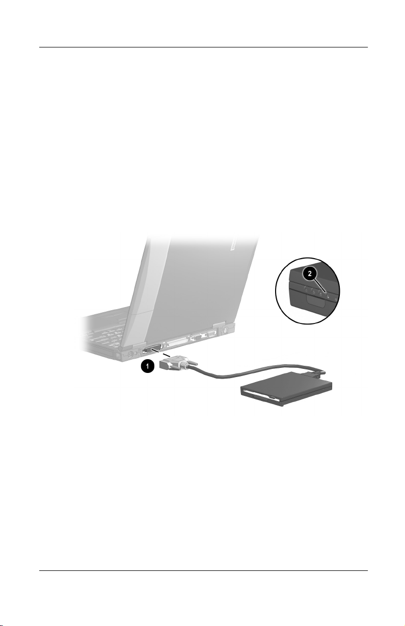
Connecting an External Diskette Drive Bay . . . . . . . . . . 7–4
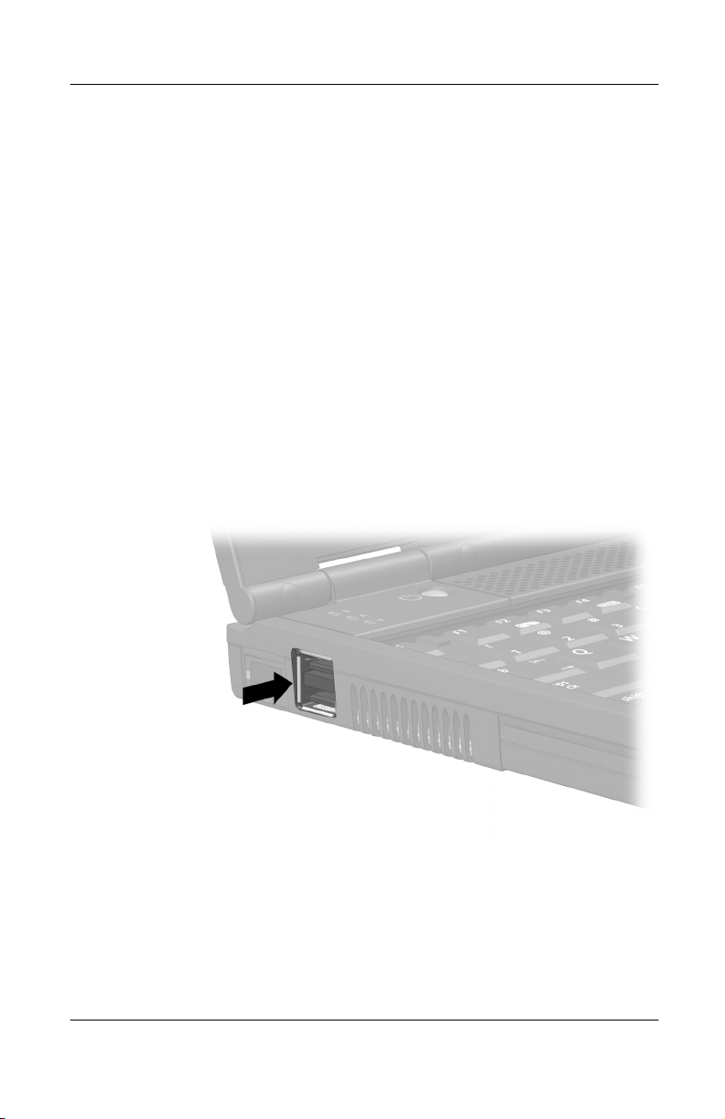
Connecting a USB Device. . . . . . . . . . . . . . . . . . . . . . . . 7–4
Using a USB Device. . . . . . . . . . . . . . . . . . . . . . . . . 7–6
Enabling USB Legacy Support. . . . . . . . . . . . . . . . . 7–6
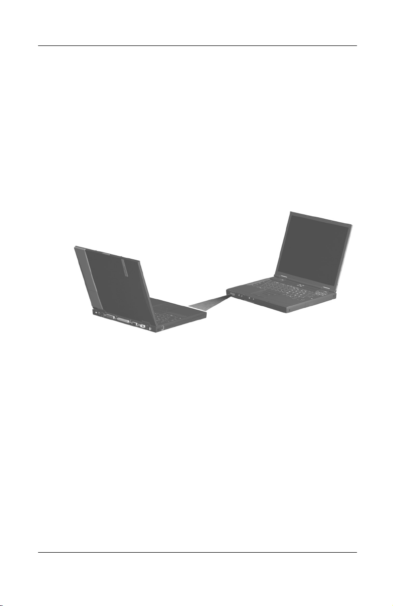
Linking to an Infrared Device . . . . . . . . . . . . . . . . . . . . . 7–7
Configuring the Infrared Port . . . . . . . . . . . . . . . . . . 7–8
Setting Up an Infrared Transmission . . . . . . . . . . . . 7–8
Using Suspend with Infrared . . . . . . . . . . . . . . . . . . 7–9
Planning a Docking System . . . . . . . . . . . . . . . . . . . . . 7–10
Docking Considerations . . . . . . . . . . . . . . . . . . . . . 7–10
Docking Alternatives . . . . . . . . . . . . . . . . . . . . . . . 7–10
Connecting an Optional Cable Lock . . . . . . . . . . . . . . . 7–11
8 Hardware Upgrades
Adding and Using PC Cards . . . . . . . . . . . . . . . . . . . . . . 8–1
Selecting a PC Card slot . . . . . . . . . . . . . . . . . . . . . . 8–1
Configuring a PC Card . . . . . . . . . . . . . . . . . . . . . . . 8–2
Inserting a PC Card. . . . . . . . . . . . . . . . . . . . . . . . . . 8–3
Removing a PC Card . . . . . . . . . . . . . . . . . . . . . . . . 8–4
Turning Off Power to a PC Card . . . . . . . . . . . . . . . 8–5
Upgrading Memory . . . . . . . . . . . . . . . . . . . . . . . . . . . . . 8–6
Viewing Memory and Hibernation File Information 8–6
Removing or Inserting a Memory Expansion Board 8–7
9 Specifications
Regulatory Agency Series Numbers . . . . . . . . . . . . . . . . 9–1
Computer Dimensions. . . . . . . . . . . . . . . . . . . . . . . . . . . 9–2
Operating Environment. . . . . . . . . . . . . . . . . . . . . . . . . . 9–2
Rated Input Power. . . . . . . . . . . . . . . . . . . . . . . . . . . . . . 9–3
Modem Specifications. . . . . . . . . . . . . . . . . . . . . . . . . . . 9–3
Index
vi Hardware Guide
Page 7

Hardware and Software Setup
Setting Up the Hardware
1
CAUTION:
To prevent file corruption, possible damage to components, and ensure
Ä
that the correct drivers load during initial setup:
■
■
■
Setup must begin with connecting the computer to AC power.
Do not set up the computer while it is docked in an optional
docking base.
Do not remove the battery pack until the computer has been
connected to external AC power.
Run the computer on external AC power, not on battery power,
throughout initial setup.
Hardware Guide 1–1
Page 8
Hardware and Software Setup
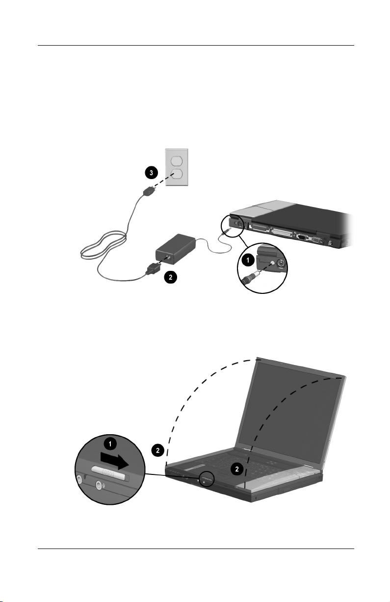
1. Place the computer on a flat surface near an electrical outlet,
then connect the computer to external AC power.
Plug the AC Adapter cable into the DC power connector 1.
Plug the power cord into the AC Adapter
electrical outlet
Connecting the computer to external power
and into an
2
. (Power cords and outlets vary by country.)
3
2. Open the computer by sliding the display release latch to the
right
Opening the computer
1–2 Hardware Guide
and raising the display 2.
1
Page 9
Hardware and Software Setup
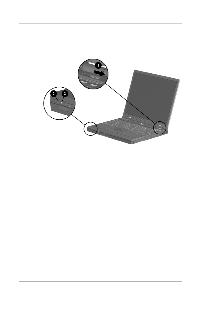
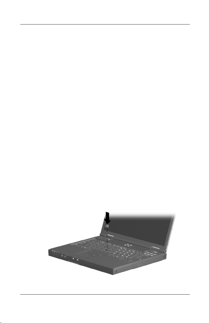
3. Turn on the computer by sliding and releasing the power
switch
Turning on the computer
1
.
When the computer is turned on:
The power/suspend light 2 turns on.
■
The battery pack in the battery bay begins to charge and the
■
battery light
turns on. The battery light remains on while
3
the battery pack is charging and turns off when the battery
pack is fully charged.
You are prompted to begin software setup.
■
Hardware Guide 1–3
Page 10

Hardware and Software Setup
Setting Up the Software
The initial setup prompt appears on the screen as soon as the
computer is connected to external power.
Before responding to the initial setup prompt and proceeding
through the online instructions, read the following caution and
initial setup information:
CAUTION: To prevent file corruption and ensure that the correct device
drivers install during initial setup:
Ä
Do not unplug the computer from the electrical outlet.
■
Do not shut down the computer.
■
Do not remove or insert a drive.
■
Once you begin initial software setup, you must complete the
■
entire process. Setup time varies by computer configuration.
If you are prompted to select a language or operating system,
■
choose carefully.
The languages and operating system that you do not
❏
choose will be deleted from the system and cannot be
restored during initial setup.
An operating system available during initial setup is
❏
enhanced by Compaq. When an operating system is
deleted, the enhancements are also deleted.
During the setup process, you must accept the End User
■
License Agreement to continue.
Installing Optional Applications
You can install third-party applications or preloaded Compaq
utilities at any time after initial setup is complete.
To install a third-party application, refer to the documentation
■
included with the application.
1–4 Hardware Guide
Page 11

To install a preloaded Compaq utility, select the Setup
■
Compaq Software icon on the Desktop, then follow the
instructions on the screen.
If the icon does not display on the Desktop after initial setup
is complete, select Start > Run. On the command line, type:
C:\cpqapps\setup.exe preload /s
To view the descriptions and space requirements of preloaded
✎
Compaq utilities without installing them, select the Setup
Compaq Software icon on the Desktop, then select Next. After
viewing the utility information, select Cancel.
After Software Setup
After the initial setup is complete, you may want to:
Calibrate the battery pack.
■
Although you can use a new battery pack that has been fully
charged to run the computer, the amount of charge in the
battery pack cannot be reported accurately until the battery
pack has been calibrated. For calibration information and
instructions, refer to the battery calibration information
included with the computer.
Hardware and Software Setup
Set the power switch, suspend button, or display switch to
■
initiate Hibernation.
Hibernation is an energy-saving feature and safeguard that
saves all information in RAM (random access memory) to a
hibernation file on the hard drive, then shuts down the
computer. When you resume from Hibernation, your work
returns to the screen where you left off. To replace a battery
pack that is the only source of power available to the
computer, you must either initiate Hibernation or shut down
the computer.
Hardware Guide 1–5
Page 12

Hardware and Software Setup
Hibernation can be initiated by default as described below,
but it may be more convenient to initiate it from a button or
switch.
Microsoft Windows 98 or Microsoft Windows 2000
❏
Professional operating system—By default Hibernation
can be initiated only from the Windows Shut Down
menu.
Microsoft Windows NT 4.0 operating system—By
❏
default Hibernation can be initiated only by pressing
the suspend button.
Fn +
For more information about using Hibernation, refer on this
CD to the Compaq Utilities guide, “Power Management”
section.
Read suggestions for creating a safe and comfortable work
■
environment. Ergonomic and safety information about the
computer is provided on this CD in the Safety & Comfort
Guide.
WARNING: To reduce the risk of personal injury, electric shock, fire, or
damage to the equipment:
Å
Do not disable the power cord grounding plug. It is an important
■
safety feature.
Plug the equipment into a grounded (earthed) electrical outlet
■
that is easily accessible at all times.
Do not place anything on power cords or cables. Arrange them
■
so that no one may accidentally step on or trip over them.
Disconnect power from the equipment by unplugging the power
■
cord from the electrical outlet.
Do not pull on a cord or cable. When unplugging from the
■
electrical outlet, grasp the cord by the plug.
1–6 Hardware Guide
Page 13

A Look at the Computer
Display Components
2
Identifying display components
Display components and their functions
Display release latch Opens the computer.
1
MultiPort Supports an optional USB-enabled
2
Hardware Guide 2–1
wireless device such as a Bluetooth,
802.11 wireless LAN, or PC Smart
Card Reader module.
Page 14

A Look at the Computer
Pointing Device Components
(Pointing Stick Models)
Identifying pointing stick components
Pointing stick components and their functions
EasyPoint IV™ 3D Pointing
1
Stick
Left and right pointing-stick
2
buttons
Scroll pointing-stick button Functions like the scroll button on an
3
2–2 Hardware Guide
Moves the pointer, selects, and
activates.
Function like the left and right buttons
on an external mouse.
external mouse.
Page 15

Pointing Device Components
(TouchPad Models)
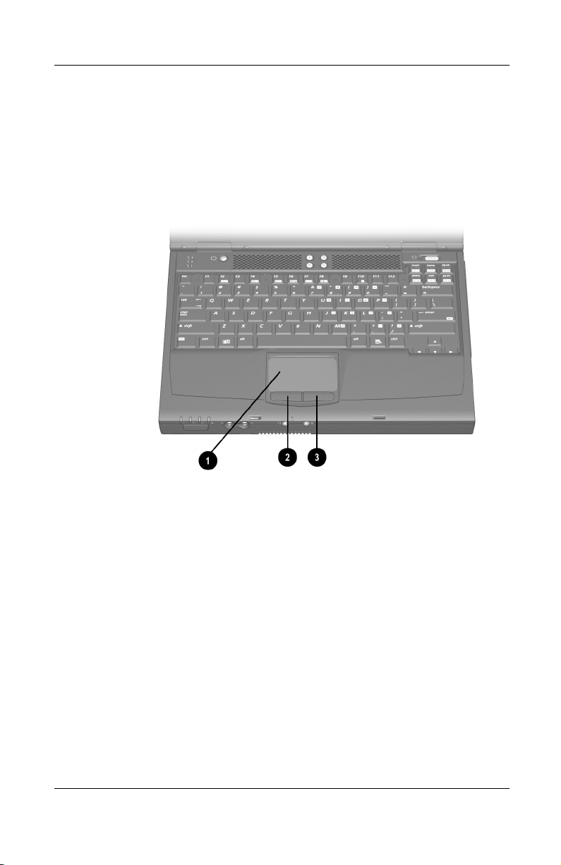
Identifying TouchPad components
A Look at the Computer
TouchPad components and their functions
TouchPad Moves the pointer, selects, and
1
Left and right TouchPad
2
buttons
Hardware Guide 2–3
activates.
Function like the left and right buttons
on an external mouse.
Page 16

A Look at the Computer
Pointing Device Components
(Dual Models)
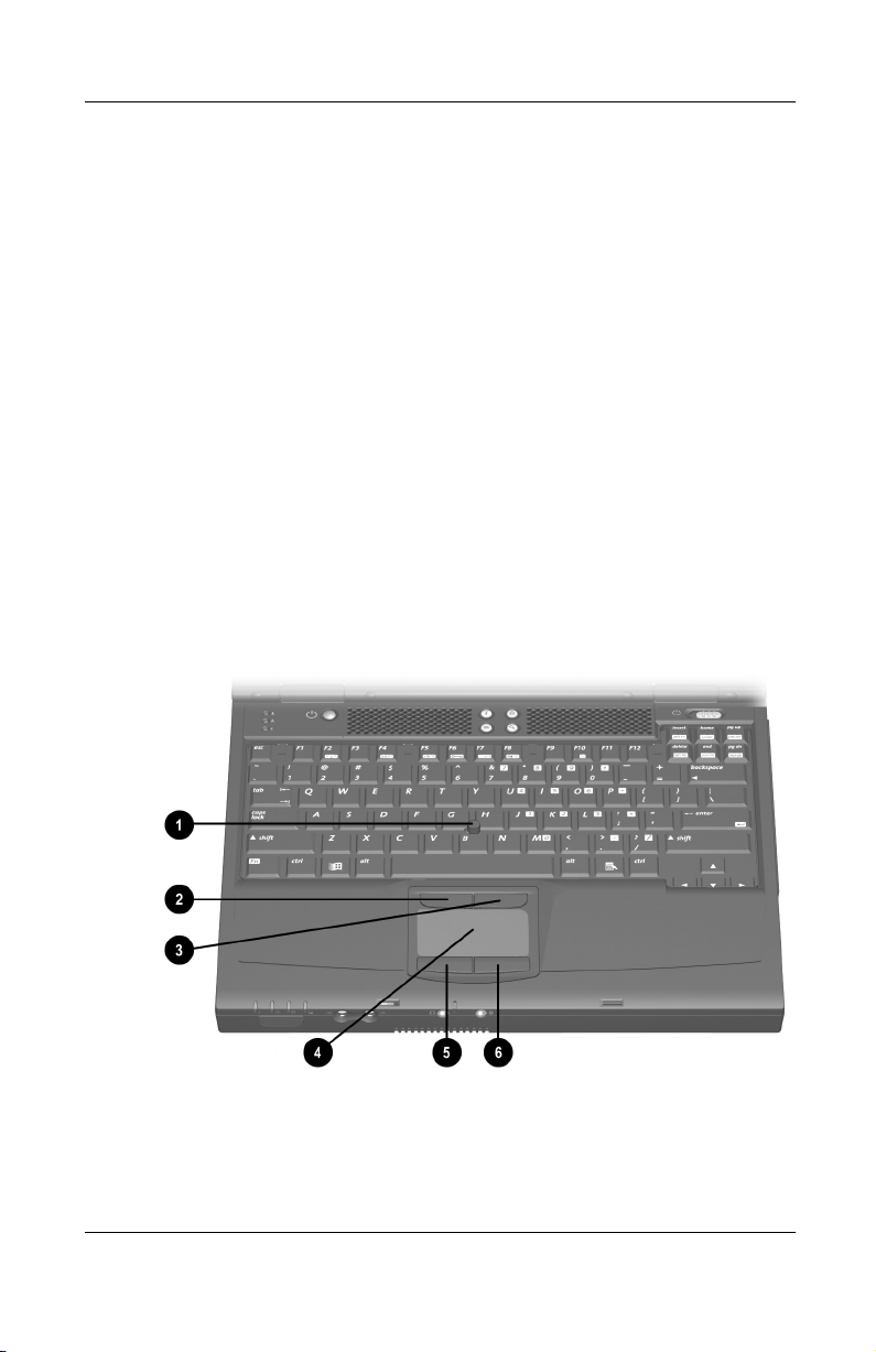
Identifying dual pointing device components
Dual pointing device components and their functions
Pointing stick Moves the pointer, selects, and
1
Left and right pointing-stick
2
buttons
TouchPad Moves the pointer, selects, and
3
Left and right TouchPad
4
buttons
2–4 Hardware Guide
activates.
Function like the left and right buttons
on an external mouse.
activates.
Function like the left and right buttons
on an external mouse.
Page 17
A Look at the Computer
Top Components: Speakers, Mini PCI Compartment
Identifying the speakers and mini PCI compartment
Speakers and mini PCI compartment and their functions
Stereo speakers (2) Produce stereo sound.
1
Mini PCI (personal
2
computer interface)
compartment
Hardware Guide 2–5
Supports an optional modem card,
combination modem/NIC (network
interface card), or other mini
PCI card.
Page 18

A Look at the Computer
Top Components: Lights
Identifying the lights on the top of the computer
2–6 Hardware Guide
Page 19

A Look at the Computer
Lights on the top of the computer and their functions
Caps lock light On: Caps lock is on.
1
Scroll lock light On: Scroll lock is on.
2
Num lock light On: Num lock is on or the embedded
3
Power/suspend light On: Power is turned on.
4
Battery light On: A battery pack is charging.
5
IDE (Integrated Drive
6
Electronics) drive light
Diskette drive light On: A standard diskette drive in the
7
†
In Windows 98 and Windows 2000 Professional, the term
replaces the term
Suspend.
numeric keypad is enabled.
Blinking: Computer is in Suspend.
The power/suspend light
✎
also blinks when a battery
pack that is the only
available power source
reaches a critical
low-battery condition while
Hibernation is disabled.
Blinking: A battery pack that is the
only available power source has
reached a low-battery condition.
On: One of the following drives is
being accessed.
■
Hard drive in the hard drive bay.
■
Optional hard drive, CD drive,
DVD drive, Zip drive, or
SuperDisk drive in the MultiBay.
MultiBay or optional external diskette
drive bay is being accessed.
Standby
†
Hardware Guide 2–7
Page 20

A Look at the Computer
Top Components: Buttons, Keys, Switches
Identifying the buttons, keys and switches on the top of the
computer
2–8 Hardware Guide
Page 21

A Look at the Computer
Buttons, keys and switches on the top of the computer
and their functions
Suspend button
1
Easy Access Buttons (4) Programmable buttons that provide
2
†
3
Power switch
Applications key Displays shortcut menu for item
4
Display release latch
5
recesses (2)
†
■
Turns on the computer if it is off.
■
Initiates and exits Suspend.
■
When pressed while sliding the
power switch, resets the
computer.
■
When pressed with Fn key,
initiates Hibernation
(Windows NT 4.0 only).
quick access to Internet or network
destinations, or to software
applications or data files in the
system.
■
Turns the computer on or off or
exits Suspend.
■
When slid while pressing the
suspend button,
computer.
beneath the pointer.
Both recesses secure the display
when it is closed.
The left recess contains the display
switch, which turns off the computer
display if the computer is closed while
‡
it is on.
†‡
†
resets the
†‡
Microsoft logo key Displays Windows Start menu.
6
†In Windows 98 and Windows 2000 Professional, the term
replaces the term
Suspend,
and the term
sleep button
Standby
replaces the term
suspend button.
‡
This table describes default settings. Other power settings, including
Hibernation settings, are available. For more information about optional
power settings, refer on this CD to the
Compaq Utilities
guide.
Hardware Guide 2–9
Page 22

A Look at the Computer
Left Side Components
Identifying left side components
Left side components and their functions
Network speed light
1
(network models only)
RJ-45 jack Connects the network cable. A network cable is
2
Network connection
3
light (network
models only)
USB connectors (2) Connect optional USB devices.
4
Exhaust vent Allows airflow to cool internal components.
5
Hard drive bay Holds the primary hard drive.
6
PC Card slots (2) Support optional 32-bit (CardBus) and 16-bit
7
PC Card eject
8
buttons (2)
On: Connection speed is 100 Mb/Sec.
Off: Connection speed is 10 Mb/Sec.
included with network models.
On: The computer is connected to a network.
Blinking: The computer is sending or receiving
information through the network.
To prevent overheating, do not
Ä
obstruct vents.
PC Cards.
Top button: Ejects an optional PC Card from the
top PC Card slot.
Bottom button: Ejects an optional PC Card from
the bottom PC Card slot.
2–10 Hardware Guide
Page 23

A Look at the Computer
Right Side Components
Identifying right side components
Right side components and their functions
Security cable slot Attaches an optional security cable to
1
the computer.
MultiBay Supports optional MultiBay devices.
2
RJ-11 jack (internal modem
3
models only)
Hardware Guide 2–11
Connects the modem cable. A
modem cable is included with internal
modem models.
Page 24

A Look at the Computer
Front Panel Components
Identifying front panel components
Front panel components and their functions
Infrared port Links another IrDA-compliant device
1
Volume buttons (2) Adjust or mute system volume.
2
for wireless communication.
Stereo speaker/headphone
3
(line-out) jack
Microphone Inputs single-channel sound; can be
4
Microphone jack Connects an optional single sound
5
2–12 Hardware Guide
Connects optional, powered stereo
speakers, headphones, headset, or
television audio.
used whether the computer is open or
closed.
channel microphone.
Page 25

A Look at the Computer
Rear Panel Components
Identifying rear panel components
Rear panel components and their functions
DC power connector Connects an AC Adapter or an
1
optional Automobile Power
Adapter/Charger, Aircraft Power
Adapter, or DC cable.
Keyboard/pointing device
2
(PS/2) connector
Parallel connector Connects an optional parallel device,
3
Docking connector Connects the computer to an optional
4
External monitor connector Connects an optional external
5
Serial connector Connects an optional serial device.
6
Composite video-out jack Connects an optional television, VCR,
7
Hardware Guide 2–13
Connects an optional PS/2 device
such as a keyboard or mouse.
To connect a keyboard and
✎
a mouse at the same time,
use an optional Y-adapter.
such as an external diskette drive bay.
docking base.
monitor or overhead projector.
camcorder, overhead projector, or
video capture card.
Page 26

A Look at the Computer
Bottom Components
Identifying bottom components
The location of the Certificate of Authenticity label (8) may vary
✎
by model and configuration.
2–14 Hardware Guide
Page 27

Bottom components and their functions
MultiBay recess Provides a grip area for removing an
1
MultiBay release latch Releases an optional MultiBay device
2
System label Provides regulatory information about
3
Serial number Identifies the computer. You will need
4
Intake vents Provide airflow to cool internal
5
Hard drive bay Secures the primary hard drive in the
6
optional MultiBay device from the
MultiBay.
from the MultiBay.
the computer.
this number if you call Compaq
customer support.
components.
To prevent overheating, do
Ä
not obstruct vents.
hard drive bay.
A Look at the Computer
Modem agency approvals
7
label (internal modem
models only)
Certificate of Authenticity
8
label
Memory expansion
9
compartment
Docking restraint latch
-
recess
Battery release latch Releases the primary battery pack
q
Battery bay Holds the primary battery pack.
w
Hardware Guide 2–15
Lists the countries in which the
modem has been approved for use.
You may need this
✎
information to use the
modem while traveling.
Contains your Product Key number.
You may need this number to update
or troubleshoot your operating
system.
Contains 2 memory expansion slots
for optional memory expansion
boards.
Helps secure the computer to a
docking base.
from the battery bay.
Page 28

A Look at the Computer
Additional Standard Components
The components included with the computer vary by
geographical region and the computer hardware configuration
ordered.
The following illustration and table identify the standard external
components included with most computer models.
This illustration does not include printed documentation or such
✎
components as the hard drive and primary battery pack, which
ship inside computer bays identified in previous sections.
Identifying additional standard components
2–16 Hardware Guide
Page 29

A Look at the Computer
Additional standard components and their functions
Powe r cord Connects the AC Adapter to an
1
AC electrical outlet.
Modem cable (internal
2
modem models only)
Country-specific modem
3
adapter (included with
internal modem models by
region as required)
Network cable (network
4
models only)
AC Adapter Converts AC power to DC power.
5
Weight saver Can replace an optional MultiBay
6
Japan-specific outlet
7
adapter (Japan only)
QuickRestore kit Contains the software preinstalled on
8
Connects the modem to an RJ-11
telephone jack or to a country-specific
modem adapter.
The modem cable has a
✎
6-pin
RJ-11 connector at
each end.
Adapts the modem cable to a
non-RJ-11 telephone jack.
Connects the computer to an
Ethernet network jack.
The network cable has an
✎
8-pin
RJ-45 connector at
each end.
device to protect the MultiBay and
reduce computer weight.
Connects the AC Adapter to a
2-prong electrical outlet.
the computer.
(Continued on next page)
Hardware Guide 2–17
Page 30

A Look at the Computer
Additional standard components and their functions
(continued)
Notebook Products
9
Reference Library
Bag containing 2 spare
-
pointing stick caps (pointing
stick and dual pointing
device models only)
CD
Contains the following guides:
■
Hardware Guide
■
Compaq Utilities
■
Modem and Networking
■
Modem Commands
■
Maintenance, Shipping
and Travel
■
Troubleshooting
■
Regulatory and Safety Notices
■
Safety & Comfort Guide
Replace worn pointing stick cap.
2–18 Hardware Guide
Page 31
3
Pointing Devices and Keyboard
Using a Pointing Device
Using the Pointing Stick (Pointing Stick Models)
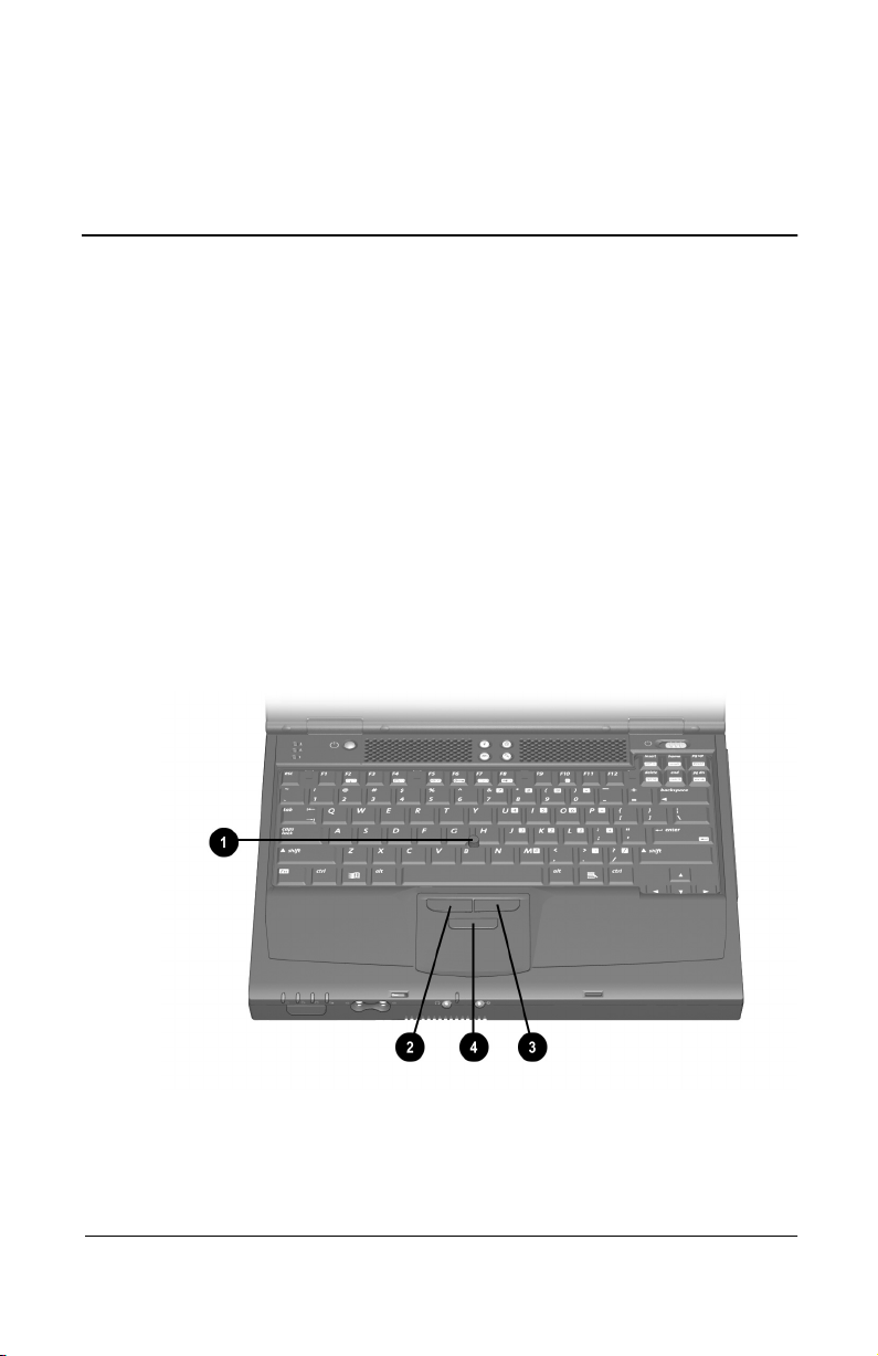
To move the cursor, press the pointing stick 1 in the direction
you want to move the cursor.
Use the left 2 and right 3 pointing-stick buttons as you would
the left and right buttons on an external mouse.
To scroll, hold down the scroll 4 button as you move the cursor.
Identifying pointing stick components
Hardware Guide 3–1
Page 32
Pointing Devices and Keyboard
Using the TouchPad (TouchPad Models)
To move the cursor, slide your finger across the TouchPad surface
in the direction you want to move the cursor.
1
Use the left 2 and right 3 TouchPad buttons as you would the
left and right buttons on an external mouse.
Identifying TouchPad components
3–2 Hardware Guide
Page 33
Pointing Devices and Keyboard
Using the Dual Pointing Device (Dual Models)
By default, the pointing stick and TouchPad components can be
used interchangeably.
Using the Pointing Stick Components
To move the cursor, press the pointing stick 1 in the direction
■
you want to move the cursor.
Use the left 2 and right 3 pointing-stick buttons as you
■
would the left and right buttons on an external mouse.
Using the TouchPad Components
To move the cursor, slide your finger across the TouchPad
■
surface
Use the left 5 and right 6 TouchPad buttons as you would
■
the left and right buttons on an external mouse.
in the direction you want to move the cursor.
4
Identifying dual pointing stick/TouchPad components
Hardware Guide 3–3
Page 34

Pointing Devices and Keyboard
Setting Pointing Device Preferences
Pointing Stick, TouchPad, and Dual Device Preferences
All pointing devices are supported by the mouse software in your
operating system. To access the custom settings available in the
software, select Start > Settings > Control Panel > Mouse.
All pointing devices perform mouse functions with any software
that supports a Windows-compatible mouse. To use a pointing
device with software that does not support a Windows-compatible
mouse:
1. Turn on or restart the computer.
2. Press
while the F10 = ROM Based Setup message is
F10
displayed in the lower left corner of the screen.
To change the language, press
❏
For navigation instructions, press
❏
3. Select Advanced > Device Options, then press
4. Select the Disable Multiple Pointing Devices checkbox, then
press
F10.
5. To save your preference(s) and exit Computer Setup, select
File > Save Changes and Exit, then follow the instructions on
the screen.
Dual Device Preferences
All dual pointing stick/TouchPad components are enabled by
default.
You can enable or disable some or all of these components in
Computer Setup:
1. Turn on or restart the computer.
2. Press
displayed in the lower left corner of the screen.
while the F10 = ROM Based Setup message is
F10
F2.
F1.
enter.
3–4 Hardware Guide
Page 35
To change the language, press
❏
For navigation instructions, press
❏
Pointing Devices and Keyboard
F2.
F1.
3. Select Advanced > Device Options, then press
4. In the Internal Pointing Devices field, select among:
Both—To enable all dual device components.
❏
Touc hPad—To enable only the TouchPad components.
❏
Pointing stick—To enable only the pointing stick
❏
components.
None—To disable all dual device pointing components.
❏
5. To confirm your preference, press
F10.
6. To save your preference and exit Computer Setup, select
File > Save Changes and Exit, then follow the instructions on
the screen.
Replacing the Pointing Stick Cap
1. Turn off the computer.
2. Gently pull off the used pointing stick cap.
3. Push a replacement cap, included with the computer,
into place.
enter.
Replacing the pointing stick cap
Hardware Guide 3–5
Page 36

Pointing Devices and Keyboard
Using Hotkeys and Shortcut Keys
Hotkeys and shortcut keys are preset combinations of the
key1 and another key that access or execute frequently used
Fn
system functions.
A hotkey is a combination of the Fn key and one of the
■
function keys
and
represent the hotkey functions available on your
F10
computer.
A shortcut key is a combination of the Fn key and a key other
■
than a function key.
. The icons on the function keys
2
F2, F4
to
F8,
Identifying hotkeys and shortcut keys
3–6 Hardware Guide
Page 37

Pointing Devices and Keyboard
Hotkey and Shortcut Key Quick Reference
Function Hotkey Return to Original State
Turn a device in the
MultiPort on or off.*
Switch display and
image.
Adjust system volume.
Initiate Quick Controls.
Set power conservation
level.
View battery charge
information.
Adjust screen
brightness.
Display system
information.
Stretch text.
*The
instructions, refer to “Turn MultiPort Device On or Off (
this section.
hotkeys can be disabled in Computer Setup. For
Fn+F2
Fn+F2 Fn+F2
Fn+F4 Fn+F4
Fn+F5 Fn+F5
Fn+F6
Enter power-on password
Fn+F7 Fn+F7
Fn+F8 Fn+F8
Fn+F10 Fn+F10
Fn+Esc Fn+Esc
Fn+T Fn+T
Fn+F2
)” later in
Hardware Guide 3–7
Page 38

Pointing Devices and Keyboard
Hotkey and Shortcut Key Procedures
Most hotkeys and shortcut keys can be used as described at
anytime and from within any application, with 2 exceptions:
To use hotkeys or shortcut keys on an external keyboard,
■
press the
scroll lock
hotkey combination. For example, to use the
press
scroll lock+scroll lock+F10.
key twice, then the other key only of the
Fn+F10
hotkeys,
The
■
Fn+F6
hotkeys (as
scroll lock+scroll lock+F6
) cannot be
used on an external keyboard connected through a USB
connector.
For information about entering hotkey commands sequentially,
refer to “Using the Fn
Key Sequentially” later in this section.
Turn a MultiPort Device On or Off (Fn+F2)
Press
receive messages) or off (to conserve power).
The status light on the device is on when power is on and off
when power is off.
The
Fn+F2
MultiPort can be set to remain on or off with the
disabled in Computer Setup. To access these settings:
1. To open Computer Setup, turn on or restart the computer,
then press
displayed. (An F10 = ROM Based Setup message is
displayed in the lower left corner of the screen.)
❏
❏
to toggle a device in the MultiPort on (to send or
Fn+F2
hotkeys are enabled by default. The device in the
Fn+F2
as soon as the Compaq splash screen is
F10
To change the language, press
To view navigation information, press
F2
.
.
F1
hotkeys
To return to the Computer Setup menu, press
❏
esc.
2. Select the Security menu.
3. Select Device Security.
3–8 Hardware Guide
Page 39

Pointing Devices and Keyboard
4. Select MultiPort Fn+F2. The status of the device in the
MultiPort is displayed at the bottom of the screen.
5. To change the status of the device in the MultiPort, press the
hotkeys. The device in the MultiPort will remain in
Fn+F2
the status you select when the
hotkeys are disabled.
Fn+F2
6. To disable the
hotkeys, set the status field beside
Fn+F2
MultiPort Fn+F2 to Disable. (To enable the
set this status field to Enable.)
7. To confirm your settings, press
F10.
8. To exit Computer Setup, select an exit option from the
File menu, then follow the instructions on the screen.
Switch Display and Image (Fn+F4)
Windows 98 with MultiMonitor disabled,
■
Windows NT 4.0, or Windows 2000 Professional—The
hotkeys support external display devices connected
Fn+F4
through the external monitor connector or the composite
video-out jack.
Togg le
Computer display
❏
External display(s)
❏
Simultaneous display on computer and
❏
external display(s)
Windows 98 with MultiMonitor enabled—The
■
hotkeys support an external display device connected through
the external monitor connector. Press
MultiMonitor and turn off the external display.
to switch the image among:
Fn+F4
Fn+F4
hotkeys,
Fn+F2
Fn+F4
to disable
Hardware Guide 3–9
Page 40

Pointing Devices and Keyboard
Adjust System Volume (Fn+F5)
Press
to display a system volume slide bar. Click and drag
Fn+F5
the slide bar upward to increase volume or downward to decrease
volume.
You also can adjust the volume by pressing
the left and right arrow keys.
To mute or restore volume, toggle
Fn+F5+M.
select or clear the Mute checkbox.
Initiate Quick Controls (Fn+F6)
Quick Control security features disable the keyboard and pointing
device and clear the display.
Before you can use the Quick Controls, you must set a power-on
password and select Quick Control preferences. For instructions,
refer on this CD to the Compaq Utilities guide, “Security”
section.
To initiate Quick Controls manually, press
Controls, enter your power-on password.
The
connected through a USB connector on the computer or an
optional docking base.
hotkeys cannot be used on an external keyboard
Fn+F6
Fn+F5,
Or, press
To exit Quick
Fn+F6.
then pressing
then
Fn+F5,
3–10 Hardware Guide
Page 41

Pointing Devices and Keyboard
Set Power Conservation Level (Fn+F7)
Windows 98 or Windows 2000 Professional—Press
■
to open the Power Schemes window.
Windows NT 4.0—Press
■
to open the Battery
Fn+F7
Conservation Settings window. To select a preset battery
conservation level, choose among:
High—Maximizes running time from a single charge.
❏
Medium—Balances system performance with
❏
running time.
None (Drain)—Runs the computer at full power.
❏
For information about the custom level, refer on this CD to
the Compaq Utilities guide, “Power Management” section.
View Battery Charge Information (Fn+F8)
Press
battery packs. The display indicates which battery packs are
charging and reports the amount of charge remaining in each
battery pack.
Battery pack locations are indicated by number: (1) is the
computer battery bay and (2) is the computer MultiBay. Any
additional locations displayed represent docking base bays, which
vary by model and configuration. Refer to your docking base
documentation for specific bay location information.
to display charge information about all installed
Fn+F8
Fn+F7
Hardware Guide 3–11
Page 42

Pointing Devices and Keyboard
Adjust Screen Brightness (Fn+F10)
Press
bar, then:
Click and drag upward on the slide bar to increase screen
■
brightness or downward to decrease screen brightness.
or
Press the left arrow key to decrease screen brightness or the
■
right arrow key to increase screen brightness.
to display the screen brightness control slide
Fn+F10
Display System Information (Fn+esc)
Press
components and software version numbers. Press
time to remove the system information from the screen.
The System BIOS date, which may display in a decimal format, is
✎
the version number of the system ROM.
to display information about system hardware
Fn+esc
Stretch Text (Fn+T)
Text stretching modes are available whenever MS-DOS is
running under Windows and the desktop area resolution is set
lower than the display resolution. Text Stretch is the default.
When Text Stretch is enabled, the text expands to fill more of the
screen. Stretching text may cause character distortion. When
Regular is enabled, a graphics accelerator cannot be used.
Fn+esc
a second
Press
3–12 Hardware Guide
to toggle the image between Text Stretch and Regular.
Fn+T
Page 43
Pointing Devices and Keyboard
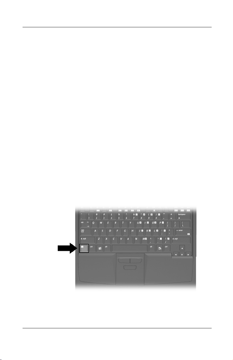
Using the Fn Key Sequentially
Many commands are entered by simultaneously pressing the
key and another key. For example, hotkey commands are
Fn
entered by pressing
If you enable sequential Fn commands, all commands that can be
entered by simultaneously pressing the
can also be entered by sequentially pressing
While this feature is enabled:
Whenever you press the Fn key, the computer beeps to
■
indicate that the next key you press will be interpreted as the
other key of an
commands can still be entered by simultaneously pressing
■ Fn
key and the other key of the Fn command.
the
Fn
To enable the sequential feature, press the Fn key 5 times. A beep
confirms that the feature is enabled. The feature remains enabled
until you disable it.
a function key.
Fn +
command.
Fn
Fn
key and another key
and the other key.
Fn
To disable this feature, press the
key 5 times. No beep sounds,
Fn
indicating that the feature has been disabled.
Identifying the Fn key
Hardware Guide 3–13
Page 44

Pointing Devices and Keyboard
Using the Embedded Numeric Keypad
The 15 keys of the embedded numeric keypad 1 can be used for
the functions indicated by the icons in the upper right corner of
each key. Enabling the numeric keypad assigns those functions to
the keypad keys. The standard functions of the keypad keys can
still be accessed while the numeric keypad is enabled.
Enabling the Numeric Keypad
To enable the numeric keypad, press
light
The numeric keypad cannot be enabled while an optional external
keyboard or keypad is connected to the computer.
Identifying embedded numeric keypad components
turns on when the numeric keypad is enabled.
3
Disabling the Numeric Keypad
Fn+num lk
2. The num lock
To disable the numeric keypad and return the keys to their
standard keyboard functions, press
3–14 Hardware Guide
Fn+num lk.
Page 45

Pointing Devices and Keyboard
Using Numeric Keypad Keys as Standard Keys
To use the numeric keypad keys temporarily as standard keys
while the numeric keypad is enabled:
Press and hold Fn to type in lowercase.
■
Press and hold
■
When the
Fn+shift
key is released, the numeric keypad functions return.
Fn
to type in uppercase.
Enabling the Numeric Keypad at Startup
By default the computer starts up with the numeric keypad
disabled. You can set the computer to start up with the numeric
keypad enabled.
The numeric keypad can be enabled or disabled with
either startup state.
To set the computer to start up with the numeric keypad enabled:
1. Turn on or restart the computer. Press
F10 = ROM Based Setup message is displayed in the lower
left corner of the screen.
To change the language, press
❏
For navigation instructions, press
❏
2. Select Advanced > Device Options, then press
3. Toggle on the Num Lock State at Boot field, then press
4. To save your preference and exit Computer Setup, select
File > Save Changes and Exit, then follow the instructions on
the screen.
F2.
while the
F10
F1.
Fn+num lk
enter.
in
F10.
To disable the numeric keypad at startup, repeat the above
procedure, toggling off the Num Lock State at Boot field.
Hardware Guide 3–15
Page 46

Pointing Devices and Keyboard
Using the Easy Access Buttons
The 4 Easy Access buttons enable you to access an Internet or
network destination or a software application or data file in your
system with a keystroke.
Using Default Settings
Until your Internet or network services are set up, all buttons
launch the Internet setup wizard for your operating system.
After your Internet or network services are set up, each button
opens your default Web browser and connects you to the default
destination represented by the icon on the button:
Identifying Easy Access buttons
Button Name Default Assignment
Information Compaq informational Web site
1
Home Personal home page
2
Search Launches AltaVista search engine
3
Email Launches Microsoft Outlook Express
4
Email application
3–16 Hardware Guide
Page 47

Pointing Devices and Keyboard
Using Custom Assignments and Schemes
Each button can be assigned to an Internet or network destination
or to any software application or data file in your system.
Button assignments can be grouped into schemes. When you
select a scheme, only the button assignments within that scheme
are active.
Button assignments and schemes can be set up, changed, or
deleted in the Easy Access buttons window. To access the
window, select Start > Settings > Control Panel > Easy Access
Keyboard icon.
For more information about using button assignments and
schemes, open the Easy Access button window, then select the
Help menu.
Hardware Guide 3–17
Page 48
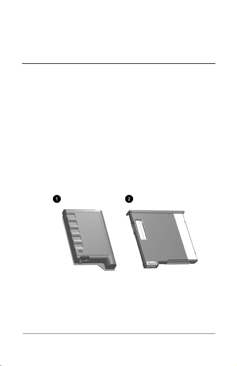
Charging Battery Packs
Any battery pack in the system charges whenever the computer is
connected to external power.
The computer supports up to 2 battery packs.
A primary battery pack 1 is an 8-cell lithium ion battery
■
pack that can be used only in the battery bay.
A MultiBay battery pack 2 is an optional 6-cell lithium ion
■
battery pack that can be used only in the MultiBay.
4
Battery Packs
Identifying a primary and a MultiBay battery pack
Multiple battery packs in the system charge and discharge in a
preset sequence determined by location.
Hardware Guide 4–1
Page 49

Battery Packs
Charge sequence:
■
1. Computer battery bay
2. Computer MultiBay
3. Docking base bay(s) (Docking base bay availability and
functionality vary by model and configuration. For
information about charging battery packs in your docking
base, refer your docking base documentation.)
Discharge sequence:
■
1. Computer MultiBay
2. Computer battery bay
While a battery pack is in a docking base bay, the battery pack
can be charged but cannot be used to run the computer.
Using a New Battery Pack
Fully charge the battery pack in the computer battery bay or the
computer MultiBay (not in a docking base bay) while the
computer is connected to an external power source or docked in a
docking base.
Although you can use a new battery pack that has been fully
charged to run the computer, battery charge displays cannot
accurately report the amount of charge in the battery pack until
the battery pack has been calibrated. For calibration instructions,
refer on this CD to the Compaq Utilities guide, “Power
Management” section, “Calibrating a Battery Pack.”
Replacing a Battery Pack
To prevent loss of information when removing a battery pack that
✎
is the only power source, initiate Hibernation or turn off the
computer before removing the battery pack.
4–2 Hardware Guide
Page 50
Replacing a Primary Battery Pack
CAUTION: To prevent loss of information when removing a primary
Ä
battery pack that is the only power source available to the system,
initiate Hibernation or turn off the computer before removing the
battery pack.
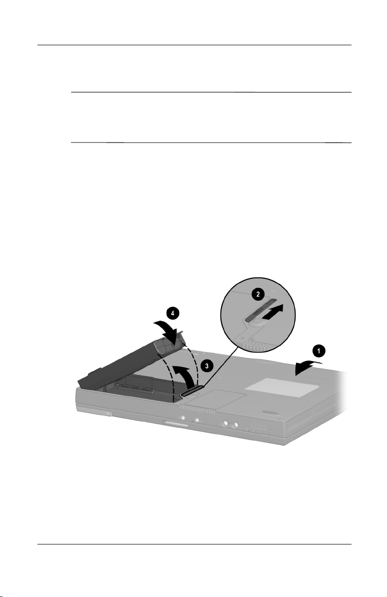
1. Close the display, then turn computer bottom-side up 1.
2. Remove or insert the battery pack.
To remove a battery pack, slide the battery release
❏
latch
from the battery bay
To insert a battery pack, slide the battery pack into the
❏
battery bay until it is seated
. When the battery pack tilts upward, remove it
2
.
3
.
4
Battery Packs
Replacing a primary battery pack
3. Turn the computer right side up, then open the display.
4. If the computer is in Hibernation, slide the power switch to
resume operation.
Hardware Guide 4–3
Page 51

Battery Packs
Replacing a MultiBay Battery Pack
CAUTION: To prevent loss of information when removing a
Ä
MultiBay battery pack that is the only power source available to the
system, initiate Hibernation or turn off the computer before
removing the battery pack.
1. Close the display, then turn the computer bottom-side up 1.
2. Insert or remove the battery pack.
To remove a battery pack, slide the MultiBay release
❏
latch
battery pack out of the MultiBay
To insert a battery pack, slide the battery pack into the
❏
MultiBay until it is seated
on the bottom of the computer, then pull the
2
3
.
4
.
Replacing a MultiBay battery pack
3. Turn the computer right side up, then open the display.
4. If the computer is in Hibernation, slide the power switch to
resume operation.
4–4 Hardware Guide
Page 52

Storing a Battery Pack
If a computer will be unused and unplugged for more than
2 weeks, remove and store the battery pack(s).
CAUTION: To prevent damage to a battery pack, do not expose it
Ä
to high temperatures for extended periods of time.
High temperatures accelerate the self-discharge rate of a stored
battery pack. To prolong the charge of a stored battery pack, place
it in a cool, dry place within the following temperature ranges.
Storage Time Temperature Range °F Temperature Range °C
Battery Packs
Less than 1
month
No more than
3 months
Unlimited 32°– 86° 0°–30°
32°–122° 0°–50°
32°–104° 0°–40°
Recycling a Used Battery Pack
To determine if a battery pack recycling program is available in
your geographical region, refer on this CD to Regulatory and
Safety Notices. If your region is not covered, refer to Wor ldw ide
Telephone Numbers, included with the computer, to contact a
Compaq authorized dealer, reseller, or service provider.
Hardware Guide 4–5
Page 53

Removable Drives
Adding a Drive to the System
Removable drives enable you to store and access data.
A standard drive can be added to the system by inserting the drive
into the computer or an optional docking base. A diskette drive
can also be inserted into an optional external diskette drive bay. In
addition, a USB drive can be added by connecting the drive to a
USB connector on the computer or an optional docking base.
For information about connecting a USB drive or an external diskette drive bay, refer in this guide to the “Connecting External
Devices” section.
The computer has 2 drive bays:
The hard drive bay supports only a hard drive. The hard drive
■
in the hard drive bay is the primary hard drive.
5
The MultiBay supports any 9.5-mm removable drive,
■
including the following:
Hard drive (inserted into a MultiBay hard drive adapter)
❏
CD drive
❏
DVD drive
❏
Diskette drive
❏
SuperDisk drive
❏
Zip drive
❏
Hardware Guide 5–1
Page 54

Removable Drives
Caring for Drives
Drives are fragile computer components that must be handled
with care.
CAUTION: To prevent damage to the computer and drive and loss of
information, ensure that you are discharged of static electricity before
Ä
handling a drive. Avoid touching the connectors on the drive.
For more information about preventing electrostatic discharge
■
damage, refer on this CD to
For additional cautions about handling drives, refer on this CD
■
to the
Maintenance, Travel and Shipping
Regulatory and Safety Notices.
guide.
Removing and Inserting a Primary Hard Drive
Any 9.5-mm hard drive can be used in the hard drive bay. No
adapter is required. The hard drive in the hard drive bay is the
primary hard drive.
CAUTION: To prevent system lockup and loss of information:
Ä
Shut down the computer before removing the hard drive from
■
the hard drive bay. Do not remove the hard drive while the
computer is on, in Suspend (Standby), or in Hibernation.
If you are not sure whether the computer is in Hibernation, turn
■
the computer on, then shut it down.
1. Save your work.
2. Shut down the computer and close the display.
3. Turn the computer bottom-side up.
5–2 Hardware Guide
Page 55
Removable Drives
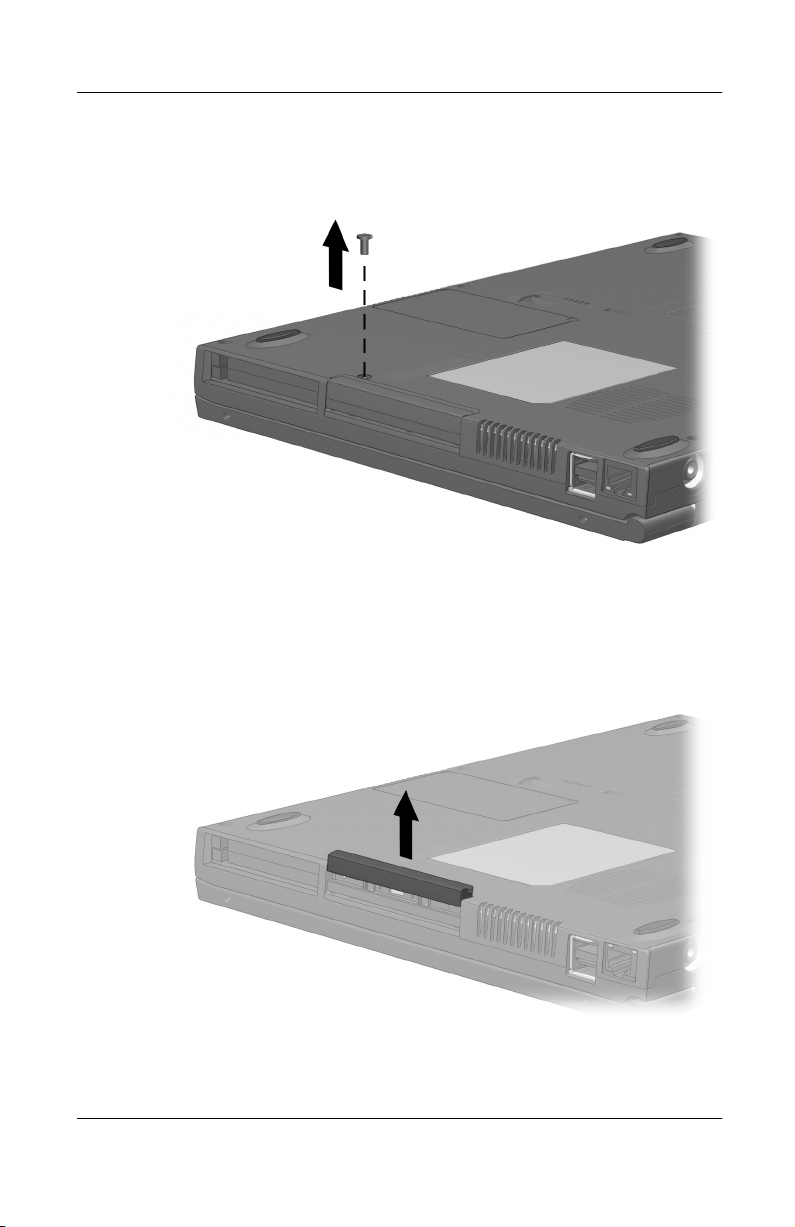
4. Remove the hard drive retaining screw.
Removing the hard drive retaining screw
5. With the drive bottom-side up, slide the bottom half of the
front bezel upward to provide a handle.
Extending the front bezel to provide a handle
Hardware Guide 5–3
Page 56
Removable Drives
6. To remove a hard drive, pull the drive out of the bay.
Removing the hard drive from the hard drive bay
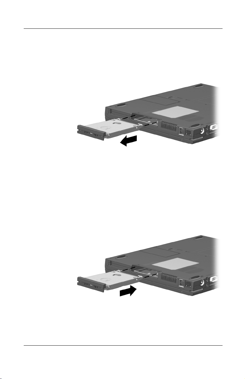
7. To insert a hard drive, slide the hard drive into the bay until
the drive is seated.
Inserting the hard drive into the hard drive bay
5–4 Hardware Guide
Page 57

Removable Drives
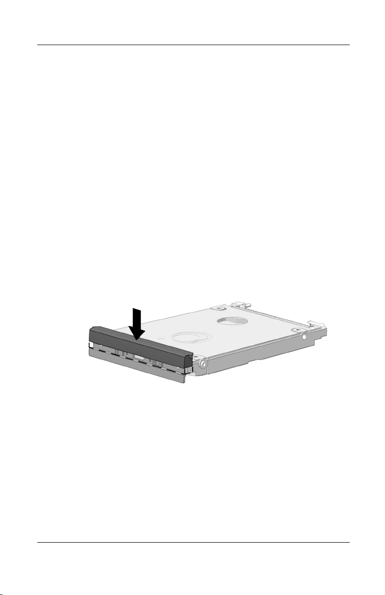
8. Close the front bezel of the hard drive.
Closing the front bezel of a hard drive
9. If you have inserted a hard drive, reinsert the hard drive
retaining screw. (If you removed but did not replace a hard
drive, put the retaining screw in a safe place.)
Replacing the hard drive retaining screw
Hardware Guide 5–5
Page 58
Removable Drives
Removing and Inserting a MultiBay Drive
Using a MultiBay Hard Drive Adapter
A hard drive must be inserted into a MultiBay hard drive adapter
before it can be used in the MultiBay.
A hard drive assembly (a hard drive inserted into a MultiBay
adapter) is inserted into and removed from the MultiBay the same
way as any other MultiBay drive.
Inserting a Hard Drive into a MultiBay Hard Drive Adapter
1. Close the front bezel of the hard drive.
Closing the front bezel of a hard drive
5–6 Hardware Guide
Page 59
Removable Drives
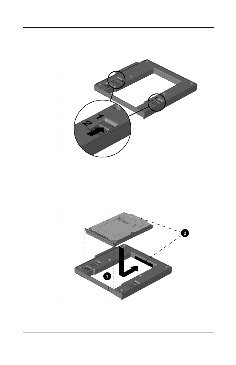
2. Slide the 2 adapter selection switches into position 1.
Sliding the adapter selection switches
3. Lower the drive into the adapter 1, then slide the drive
connectors on the drive toward the drive connectors in the
adapter
until the connectors engage and the drive is seated.
2
Inserting a hard drive into a MultiBay hard drive adapter
Hardware Guide 5–7
Page 60

Removable Drives
Removing a Hard Drive from a MultiBay Hard Drive
Adapter
1. Slide the adapter release latch toward the left.
Sliding the adapter release latch
5–8 Hardware Guide
Page 61

Removable Drives
2. Gently disengage the drive connectors 1 by sliding the drive
toward the front of the adapter.
3. Remove the drive from the adapter 2.
Removing a hard drive from a MultiBay hard drive adapter
Removing a Drive from the MultiBay
CAUTION: To prevent system lockup and loss of information:
■
Windows 98 or Windows NT 4.0—Shut down the computer
before removing a hard drive or a Zip drive from the MultiBay.
Do not remove a hard drive or a Zip drive while the computer is
on, in Suspend (Standby), or in Hibernation. If you are not sure
whether the computer is in Hibernation, turn the computer on,
then shut it down.
■
Windows 2000 Professional—Before removing any drive, stop
the drive by selecting the Unplug or Eject Hardware icon in the
taskbar, then select the drive you plan to remove.
Hardware Guide 5–9
Page 62
Removable Drives
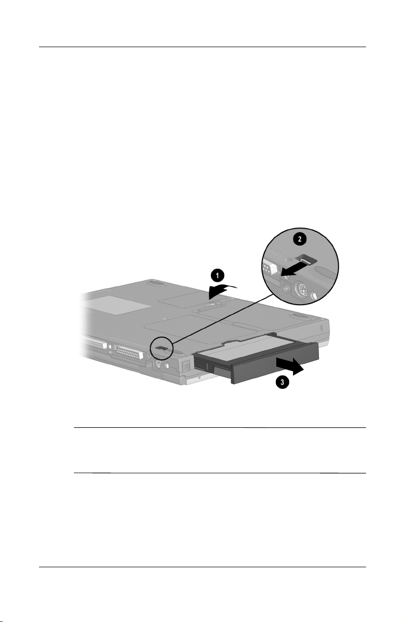
1. If the drive has a media tray, remove the media, then close
the tray.
2. Follow the instructions in the preceding caution, then close
the display.
3. Turn the computer bottom-side up 1.
4. Slide the MultiBay release latch 2 toward the rear of
the computer.
5. Pull the drive or drive assembly out of the MultiBay 3.
Removing a drive from the MultiBay
When no device is in the MultiBay, insert the weight saver to
✎
reduce computer weight and protect the bay opening. The weight
saver can be inserted or removed at any time.
5–10 Hardware Guide
Page 63
Inserting a Drive into the MultiBay
1. Before inserting a hard drive into the MultiBay:
Insert the drive into a MultiBay hard drive adapter as
❏
described earlier in this section.
Ensure that the hard drive bezel is closed before inserting
❏
the hard drive assembly (a hard drive inserted into a
MultiBay hard drive adapter) into the MultiBay.
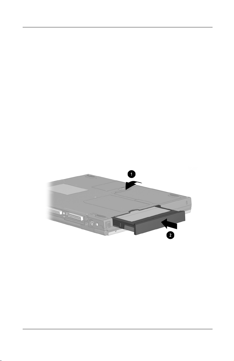
2. Turn the computer bottom-side up 1.
3. With the connector on the drive or drive assembly facing into
the MultiBay, slide the drive or drive assembly into the
.
MultiBay until it is seated
2
Removable Drives
Inserting a hard drive assembly into the MultiBay
Hardware Guide 5–11
Page 64
Removable Drives
Inserting and Removing Drive Media
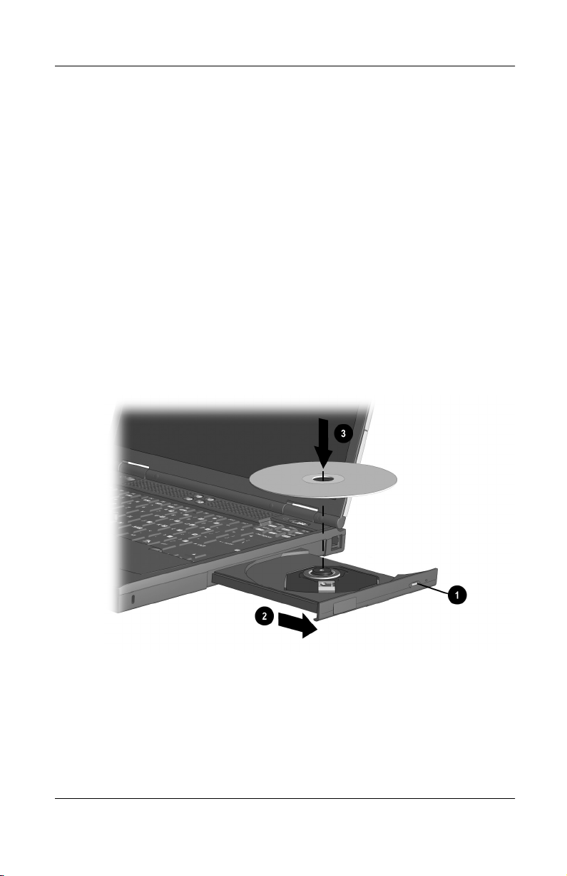
Inserting a CD, CD-RW or DVD
1. Turn on the computer.
2. Press the media release button 1 on the drive bezel to release
the media tray, then pull the tray outward until it is fully
extended
3. Press the disc onto the tray spindle 3. Handle the disc by the
edges, not the flat surfaces. (If the media tray is not fully
extended, tilt the disc to position it over the tray spindle, then
press it downward into position.)
4. Close the media tray.
2
.
Inserting a disc into a CD or DVD drive
5–12 Hardware Guide
Page 65

Removable Drives
Removing a CD, CD-RW or DVD (Power)
If power is available:
1. Turn on the computer.
2. Press the release button 1 on the drive bezel to release the
media tray, then pull the tray outward until it is fully
extended
3. Remove the disc from the tray 3. (If the media tray is not
fully extended, tilt the disc as you remove it.) Handle the disc
by the edges, not the flat surfaces. To protect the disc, place it
in a protective case.
4. Close the media tray.
2
.
Removing a disc from a CD or DVD drive while power is
available
Hardware Guide 5–13
Page 66
Removable Drives
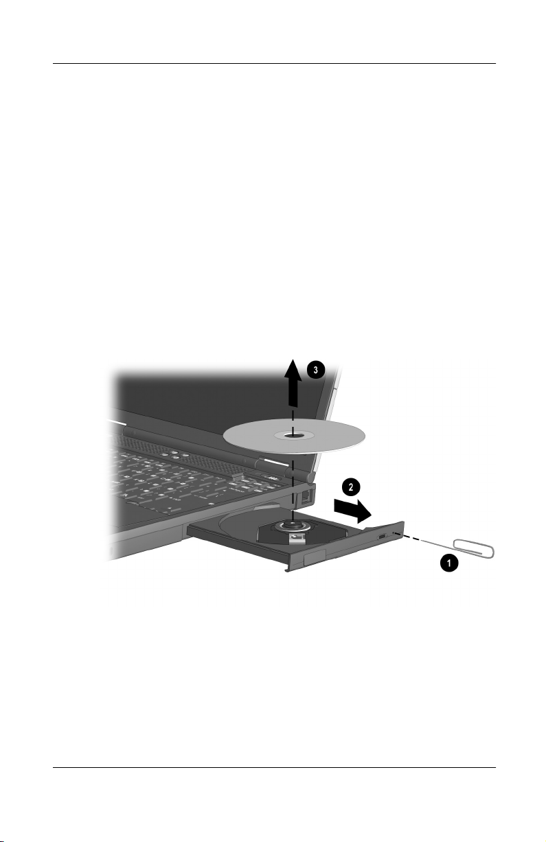
Removing a CD, CD-RW or DVD (No Power)
If power is unavailable:
1. Insert a paper clip into the release access 1 in the front bezel
of the drive.
2. Press gently on the paper clip until the media tray is released,
.
then pull out the tray until it is fully extended
3. Remove the disc from the tray 3. (If the media tray is not
fully extended, tilt the disc as you remove it.) Handle the disc
by the edges, not the flat surfaces. To protect the disc, place it
in a protective case.
4. Close the media tray.
2
Removing a disc from a CD or DVD drive while power is not
available
5–14 Hardware Guide
Page 67

Inserting a Diskette or Disk
To insert a diskette or disk into a diskette, SuperDisk, or Zip
drive: Gently push the medium, label side up, into the drive until
it clicks into place.
The media eject button ejects to show the medium is inserted
correctly.
Removing a Diskette or Disk
To remove a diskette or disk from a diskette, SuperDisk, or Zip
drive:
1. Press the media eject button on the drive to eject the medium.
2. Remove the medium from the drive.
Using Drive Media
Displaying Media Contents
Removable Drives
When a medium such as a CD, CD-RW, DVD, disk, or diskette is
inserted into a drive, the contents of the medium display on the
screen if autorun is enabled.
To display the contents of a medium when autorun is not enabled:
1. Click Start > Run, then type:
X: (where X = the designation of the drive containing
the medium)
2. Press
Hardware Guide 5–15
enter.
Page 68

Removable Drives
Initiating Suspend or Hibernation
CAUTION: To prevent possible video degradation and loss of audio
Ä
or video playback functionality, do not initiate Suspend or
Hibernation while playing any media.
To ensure a standard initiation of and exit from Suspend or
Hibernation, turn off all media before initiating Suspend
or Hibernation.
Depending on your configuration, initiating Suspend or
Hibernation while playing any media may result in:
Anomalous playback after resuming from Suspend
■
or Hibernation.
An error message denying the initiation of Suspend
■
or Hibernation.
If Suspend or Hibernation is accidentally initiated while a
medium is playing:
1. Resume from Suspend or Hibernation by sliding the
power switch.
2. Restart the computer.
For more information about Suspend and Hibernation, refer on
this CD to the Compaq Utilities guide, “Power Management”
section. For more information about troubleshooting problems
with Suspend, Hibernation, or audio or video functionality, refer
on this CD to the Troubleshooting guide.
5–16 Hardware Guide
Page 69
Audio and Video
Using Audio Features
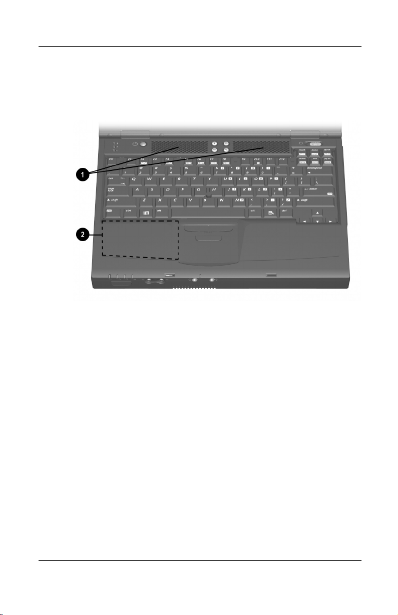
Identifying Audio Features
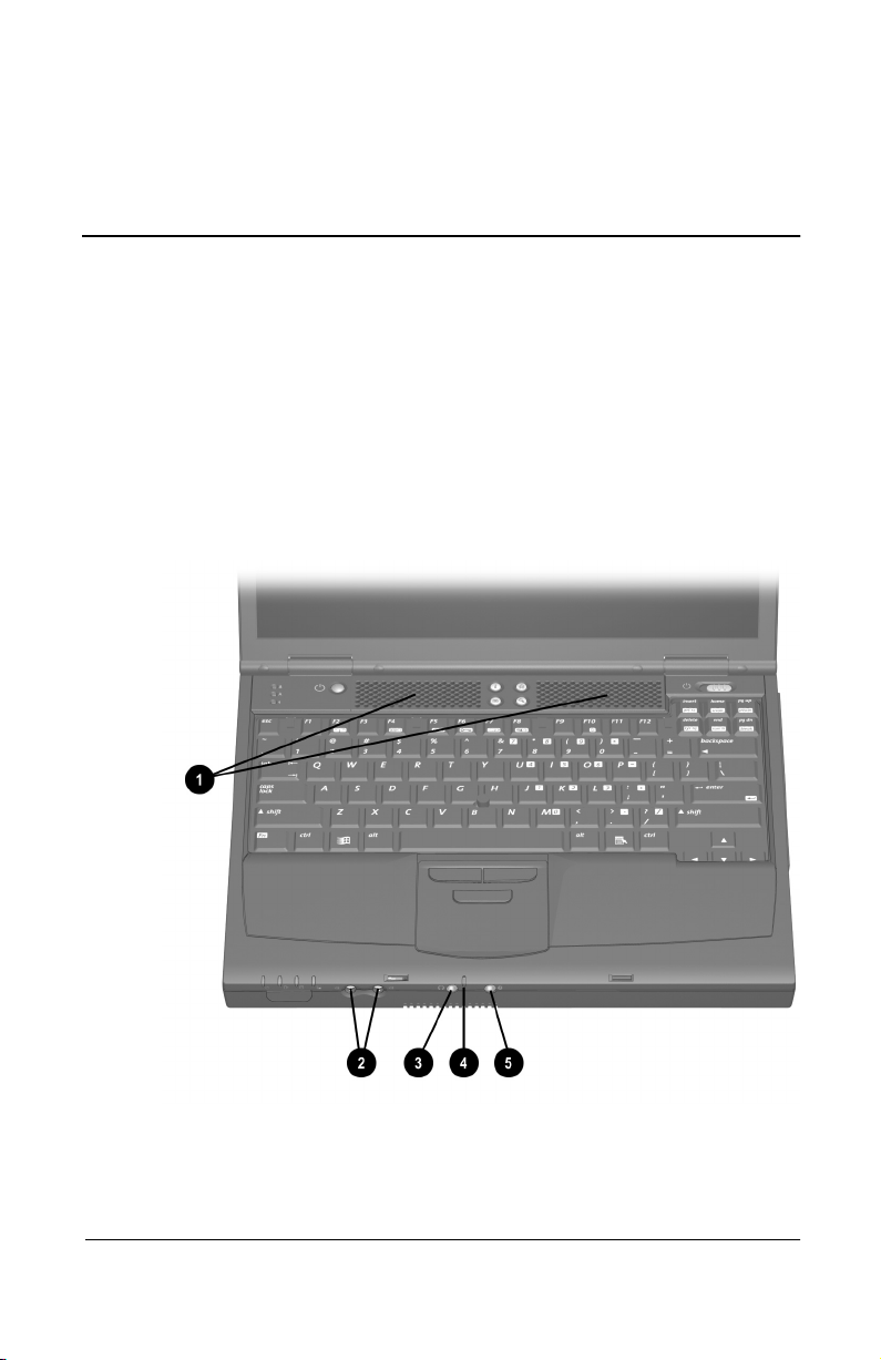
The computer provides the following audio components:
6
Identifying audio features
Hardware Guide 6–1
Page 70

Audio and Video
Audio Feature Function
Speakers (2) Provide stereo audio playback for multimedia
1
Volume butt on s Adjust or mute system volume.
2
applications.
When the computer is docked in an
✎
optional docking base, the computer
speakers are disabled and system
sound plays through the docking
base speakers. For more
information, refer to the
documentation included with the
expansion base.
Stereo speaker/
3
headphone
(line-out) jack
Microphone Supports audio input whether the display is
4
Microphone jack Supports a single sound channel (monaural)
5
Connects powered stereo speakers,
headphones, a headset, or an audio/visual
device such as a television or VCR.
open or closed; has a standard sensitivity of
-50 dB.
microphone.
Using the Microphone Jack
When connecting a microphone to the microphone jack, use a
single sound channel (monaural) microphone with a 3.5-mm
plug. A monaural electret condenser microphone is
recommended.
If you connect a stereo microphone, left channel sound will
■
record on both channels.
If you connect a dynamic microphone, the recommended
■
sensitivity may not be achieved.
When an external microphone is connected to the computer, the
computer microphone is disabled.
6–2 Hardware Guide
Page 71

Audio and Video
Using the Stereo Speaker/Headphone Jack
WARNING: To reduce the risk of personal injury, adjust the volume
Å
before putting on headphones or a headset.
CAUTION: To prevent possible damage to an external device, do
Ä
not plug a single-sound channel (monaural) connector into the
stereo speaker/headphone (line-out) jack.
When connecting a device to the stereo speaker/headphone
(line-out) jack:
Use only a 3.5-mm stereo plug.
■
For best sound quality, use 24- 32-ohm headphones.
■
When an external audio device is connected to the stereo
speaker/headphone (line-out) jack, the computer stereo speakers
are disabled.
Adjusting Volume
To adjust volume, use any of the following controls:
Computer volume buttons
■
To increase volume, press the right button.
❏
To decrease volume, press the left button.
❏
To mute or restore volume, press both buttons
❏
simultaneously.
Keyboard
■
To increase or decrease volume, press
❏
move the slide bar on the screen or press the keyboard
arrow keys.
To mute or restore volume, toggle
❏
Fn+F5,
Hardware Guide 6–3
hotkeys
Fn+F5
then
Fn+F5,
Fn+F5+M.
then select or clear the Mute check box.
Or, press
Page 72

Audio and Video
Windows Volume Control window
■
To open the window and access the volume settings,
❏
double-click the volume icon on the taskbar.
To activate the Widows Volume Control window while it
❏
is open but inactive, press the
Volume can also be adjusted within some applications.
✎
Using Video Features
The composite video-out jack supports video signals only.
The jack can be used with any device that accepts video-in
through a standard composite video connector. Supported devices
include televisions, VCRs, camcorders, overhead projectors, and
video capture cards.
If you are setting up a configuration that combines audio and
video functions, such as playing a DVD movie to a television,
connect the device audio to the stereo/speaker headphone
(line-out) jack.
Fn+F5
hotkeys.
The computer can support one composite video device connected
to the composite video-out jack while simultaneously supporting
an image on the computer display and on any other supported
external displays.
Using the Composite Video-Out Jack
To transmit video signals through the composite video-out jack,
you need a standard composite video cable available from most
television, VCR, or electronics retailers.
6–4 Hardware Guide
Page 73

Audio and Video
To connect a video device to the composite video-out jack:
1. Plug either end of the composite video cable into the
composite video-out jack on the computer
2. Connect the other end of the cable to the video device as
instructed in the device documentation
2
.
1
.
Connecting a device to the composite video-out jack
Changing the Video Mode
Color television standard modes vary even within regions.
✎
However, NTSC is common in North America; PAL, in Europe,
China, Africa, and the Middle East; NTSC-J, in Japan; and
PAL-M, in Brazil. Other South and Central American regions
may use NTSC, PAL, or PAL-M.
The default color television standard mode is NTSC.
Hardware Guide 6–5
Page 74

Audio and Video
To change the color television standard mode from NTSC:
1. Turn on or restart the computer. Press
while the
F10
F10 = ROM Based Setup message is displayed in the lower
left corner of the screen.
To change the language, press
❏
For navigation instructions, press
❏
2. Select Advanced > Device Options, then press
3. Enter your preference, then press
F2.
F1.
enter.
F10.
4. To save your preference and exit Computer Setup, select
File > Save Changes and Exit, then follow the instructions on
the screen.
6–6 Hardware Guide
Page 75

External Device Connections
Connecting a Standard Device
The jacks and connectors described in this guide support the
standard external devices that specify them.
For information about which jack or connector to use, refer to
■
the documentation included with the device.
For information about installing or loading any software such
■
as drivers required by the device, refer to the device
documentation, your operating system documentation, or the
device manufacturer’s Web site.
To connect both a pointing device and a keyboard to the
■
keyboard/pointing device (PS/2) connector, use a Y-adapter.
A Y-adapter can be purchased from most computer or
electronics retailers.
To connect a standard external device to the computer:
7
1. If you are connecting a powered device, be sure the device is
turned off.
2. Connect the device to a jack or connector on the computer.
3. If you are connecting a powered device, plug the device
power cord into a grounded electrical outlet.
4. Turn on the device.
If a properly connected external monitor does not display an
✎
image, try pressing the
monitor.
Hardware Guide 7–1
hotkeys to switch the image to the
Fn+F4
Page 76

External Device Connections
Connecting a Modem Cable
A modem cable, which has a 6-pin RJ-11 connector at each end,
must be connected to an analog telephone line. Jacks for digital
PBX systems may resemble analog telephone jacks, but are not
compatible with the modem. Immediately disconnect an
accidental connection to a digital line.
1. If the modem cable contains noise suppression circuitry 1,
which prevents interference from TV and radio reception,
orient the circuitry end of the cable toward the computer.
2. Plug the modem cable into the RJ-11 jack on the computer 2.
WARNING: To reduce the risk of electrical shock, fire, or damage to
Å
the equipment, do not plug a telephone cable into the RJ-45 jack.
3. If you are connecting the cable to a telephone jack that is not
an RJ-11 jack, plug a country-specific modem adapter into
the telephone jack
4. Plug the modem cable into the country-specific modem
adapter or into an RJ-11 telephone jack
3
.
4
.
Connecting a modem cable
7–2 Hardware Guide
Page 77
For more information about using the modem or about using
AT commands and dial modifiers, refer on this CD to the
Modem and Networking guide or the Modem Commands guide.
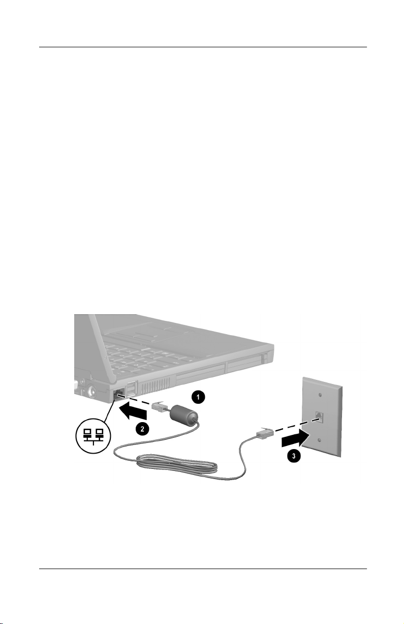
Connecting a Network Cable
A network cable has an 8-pin RJ-45 connector at each end and
may contain noise suppression circuitry, which prevents
interference with TV and radio reception.
1. Orient the end of a network cable with noise suppression
circuitry
2. Plug the network cable into the RJ-45 jack 2.
3. Plug the other end of the cable into a network jack 3.
4. Start or restart the computer.
5. Connect to the network.
toward the RJ-45 jack on the computer.
1
External Device Connections
Connecting a network cable
For more information about using a network, refer to the Modem
and Networking guide on this CD.
Hardware Guide 7–3
Page 78
External Device Connections
Connecting an External Diskette Drive Bay
An optional external diskette drive bay supports only a diskette
drive. No other type of drive, including a SuperDisk or Zip drive,
can be used in this bay.
To connect the external diskette drive bay, connect the free end of
the diskette drive bay cable to the parallel connector on the
computer
computer.
When a diskette drive in the external diskette drive bay is being
accessed, the diskette drive light on the computer turns on
. To disconnect the bay, disconnect the cable from the
1
2
.
Connecting or disconnecting an external diskette drive bay
Connecting a USB Device
USB (Universal Serial Bus) is a hardware interface that can be
used to connect such low-speed external devices as a USB
keyboard, mouse, drive, printer, scanner, or hub to the computer
or an optional docking base.
7–4 Hardware Guide
Page 79
External Device Connections
USB hubs can be connected to a USB connector on the computer
or a docking base or to other USB devices. Hubs support varying
numbers of USB devices and are used to increase the number of
USB devices in the system:
Powered hubs must be connected to external power.
■
Unpowered hubs must be connected either to a USB
■
connector on the computer or to a port on a powered hub.
A USB connector on the computer or a docking base supports
USB devices only if the computer is running an operating system
that supports USB. Windows 98 and Windows 2000 Professional
support USB. Windows NT 4.0 does not.
Some USB devices may require additional support software,
which is usually included with the device. For more information
and software installation instructions, refer to the documentation
included with the device.
Identifying the 2 USB connectors on the computer
Hardware Guide 7–5
Page 80

External Device Connections
Using a USB Device
USB devices function in the system the same as comparable
non-USB devices, with 1 exception:
By default, USB devices do not function unless an operating
system that supports USB is loaded.
To use a USB keyboard, mouse, or hub connected to a USB
connector on the computer during startup or in a non-Windows
application or utility, enable USB legacy support.
Enabling USB Legacy Support
1. Turn on or restart the computer, then press
while the
F10
F10 = ROM Based Setup message is displayed in the lower
left corner of the screen.
To change the language, press
❏
For navigation instructions, press
❏
F2.
F1.
2. Select the Advanced menu > Device Options.
3. Select Enable USB legacy support.
4. To save your preference and exit Computer Setup, select
File > Save Changes and Exit, then follow the instructions on
the screen.
7–6 Hardware Guide
Page 81
External Device Connections
Linking to an Infrared Device
If the computer is running Windows 98 or Windows 2000
Professional, the computer is IrDA-compliant (4 Mbps standard)
and can communicate with another infrared-equipped device that
is also IrDA-compliant.
Infrared signals are sent through an invisible beam of infrared
light and require an unobstructed line of sight path.
Linking to an infrared device
The infrared port supports both low speed connections up to
115 kilobits per second (Kbps) and high speed connections up to
4 megabits per second (Mbps).
Infrared performance may vary depending on performance of
infrared peripherals, distance between infrared devices, and
applications used.
Hardware Guide 7–7
Page 82

External Device Connections
Configuring the Infrared Port
If you are using optional infrared software and a preinstalled
operating system, the following information may be helpful.
The infrared port default settings are:
■
DMA=1
❏
I/O addresses=3E8-3EFh
❏
IRQ=3
❏
The optimal port selections in Direct Cable Connection are:
■
Windows 98—Serial Cable on COM4 or Parallel Cable
❏
on LPT3.
Windows 2000 Professional—Infrared Port.
❏
Setting Up an Infrared Transmission
For information about using infrared software, refer to your
operating system Help file.
To set up infrared devices for optimal transmission:
Prepare the infrared ports on both devices for transmission.
■
Windows 98—Both the computer infrared port and
❏
Infrared Monitor Search must be enabled. The port is
enabled by default each time the computer starts up. To
enable Infrared Monitor search, select the infrared icon in
the taskbar > Options tab. Select the Search For and
Provide Status for Devices in Range checkbox, then
select OK.
Windows 2000 Professional—The computer infrared
❏
port is fully enabled whenever the computer is on.
Position the devices so their infrared ports face each other at a
■
distance no greater than 3.3 feet (1 meter).
7–8 Hardware Guide
Page 83

Position the ports so they face each other directly. Because
■
the maximum capture angle is 30 degrees, the ports must be
aligned no more than 15 degrees off center.
Shield the ports from direct sunlight, flashing incandescent
■
light, and energy-saving fluorescent light.
Be sure no signals from remote control or other wireless
■
devices, such as headphones or audio devices, aim at a port.
During the transmission, do not move either device and do
■
not allow objects or movement to disrupt the beam.
Using Suspend with Infrared
When Suspend (Standby) occurs while the infrared port is
enabled, the performance of each feature is as follows:
Windows 98 with Infrared Monitor Search enabled:
■
You can establish an infrared link.
❏
The system cannot initiate Suspend (Standby).
❏
User-initiated Suspend (Standby) is not affected.
External Device Connections
Windows 98 with Infrared Monitor Search disabled:
■
You cannot establish an infrared link.
❏
Suspend (Standby) can be initiated manually or by
❏
the system.
Power is conserved.
❏
Windows 2000 Professional—Both system-initiated
■
Suspend (Standby) and user-initiated Suspend prevent or
interrupt an infrared transmission.
When the computer exits Suspend, an interrupted
transmission resumes.
Hardware Guide 7–9
Page 84

External Device Connections
Planning a Docking System
The computer is compatible with all 3 Compaq docking
solutions: the Expansion Base, the Convenience Base, and the
Port Replicator.
Docking Considerations
To ensure convenient access to the computer and its features,
Compaq recommends that you consider the following before
setting up your docking system.
When the computer is used with any docking base:
■
The computer cannot be docked while a PC Card or
❏
PC Card cable is protruding from the lower PC Card slot.
The lower PC Card slot is not accessible while the
❏
computer is docked. (Type III PC Cards, which fill both
PC Card slots, are inserted into the lower PC Card slot.)
The computer should not be docked or undocked while
❏
NIC (Network Interface Card) or USB (Universal Serial
Bus) cables are connected to the computer. NIC and USB
cables can be connected or disconnected while the
computer is docked.
When the computer is used with an Expansion Base in a
■
vertical stand, all features on the left side of the computer,
such as PC Card slots and eject buttons, USB ports, and the
RJ-45 jack (NIC connector) are inaccessible.
Docking Alternatives
You can set up your docking system to provide access to the
features you use by doing any of the following:
Create an alternative NIC connection by installing a PCI card
■
NIC in an Expansion Base or Convenience Base.
7–10 Hardware Guide
Page 85

External Device Connections
Connect your accessories to the USB port on an Expansion
■
Base, Convenience Base, or Port Replicator instead of to a
USB port on the computer.
To use a wireless LAN (Local Area Network) while the
■
computer is docked in an Expansion Base in a vertical stand,
install a Compaq 802.11b MultiPort Wireless LAN module in
the computer.
Connecting an Optional Cable Lock
Loop the cable around a secure object, then insert the security
cable lock
cable lock key
into the security cable slot 2 and lock it with the
1
.
3
Connecting an optional cable lock
Hardware Guide 7–11
Page 86

Hardware Upgrades
To order or learn more about hardware upgrades and accessories,
visit the Compaq Web site at
Worldwide Telephone Numbers, included with the computer, to
contact a Compaq authorized dealer, reseller, or service provider.
For information about obtaining and installing software updates
and upgrades, refer on this CD to the Maintenance, Shipping and
Travel guide, “How to Get Information, Updates and Help”
section. If you prefer a printed version of this section, refer to the
“How to Get Information, Updates and Help” section of the
printed Getting Started guide, included with the computer.
Adding and Using PC Cards
A PC Card is a credit card–sized accessory designed to conform
to the standard specifications of the Personal Computer Memory
Card International Association (PCMCIA). The computer
supports both 32-bit CardBus and 16-bit PC Cards.
http://www.compaq.com,
8
or refer to
Selecting a PC Card slot
PC Cards are classified as Type I, Type II, and Type III. The 3
types are about the same length and width, but vary in thickness.
Type I and Type II PC Cards can be used in the top or
■
bottom PC Card slot singly or in any combination.
A Type III PC Card can be used only in the bottom
■
PC Card slot.
Zoomed video PC Cards are not supported in either slot.
■
Hardware Guide 8–1
Page 87

Hardware Upgrades
When the computer is used with any docking base:
The computer cannot be docked while a PC Card or cable is
■
protruding from the lower PC Card slot.
The lower PC Card slot is inaccessible while the computer is
■
docked.
When the computer is used with an Expansion Base in a vertical
stand, both PC Card slots and PC Card eject buttons are
inaccessible.
Configuring a PC Card
CAUTION: If you install all of the software or any of the enablers
provided by a PC Card manufacturer, you may not be able to use other
Ä
PC Cards. If you are instructed by the documentation included with
your PC Card to install device drivers:
Install only the device drivers for your operating system.
■
Do not install other software, such as card services, socket
■
services, or enablers, that may also be supplied by the PC Card
manufacturer.
Windows 98 and Windows 2000 Professional configure plug and
play PC Cards.
To configure a PC Card In Windows NT 4.0 with CardWare
provided by Compaq:
1. Insert the PC Card.
2. Select Start > Programs > CardWare to open the
CardWare window.
3. Follow the instructions on the screen. For additional
instructions, select the Help menu within CardWare.
8–2 Hardware Guide
Page 88

Inserting a PC Card
CAUTION: To prevent damage to the connectors, use minimal
Ä
pressure when inserting a PC Card into a PC Card slot.
CAUTION: Failure to remove a PC Card that extends beyond the
Ä
computer before transporting the computer may cause permanent
damage to the PC Card connectors.
1. Hold the PC Card label-side up with the connector facing
the computer.
2. Gently push the card into the slot until the card is seated.
Hardware Upgrades
Inserting a PC Card into a PC Card slot
3. In Windows NT 4.0 with CardWare provided by Compaq,
restart the computer if you are instructed to do so by the
PC Card documentation or a prompt on the screen.
Hardware Guide 8–3
Page 89
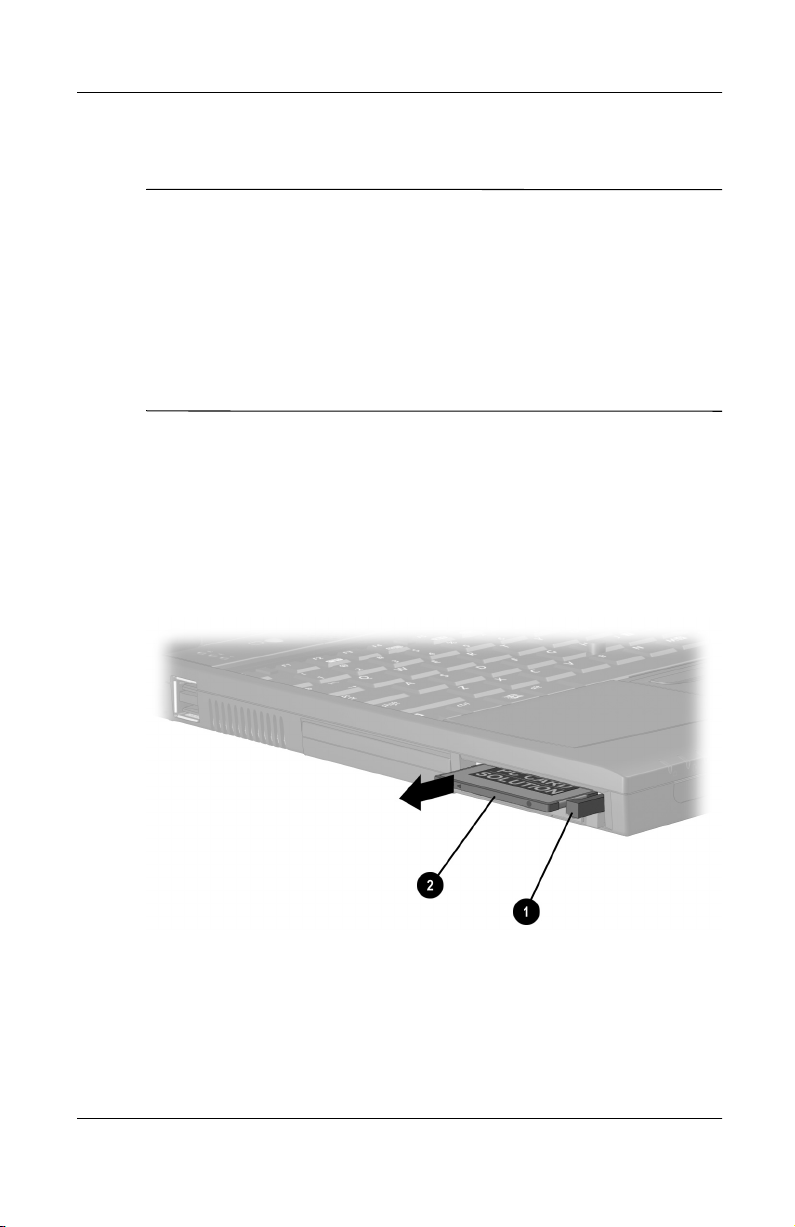
Hardware Upgrades
Removing a PC Card
CAUTION: To prevent loss of work or system lockup:
Ä
■
Windows 98—Select the PC Card icon in the taskbar, then
stop the card you plan to remove. A message displays when the
card can be safely removed.
■
Windows 2000 Professional—Select the Unplug or Eject icon
in the taskbar, then stop the card you plan to remove. A
message displays when the card can be safely removed.
■
Windows NT 4.0 with CardWare provided by Compaq—If
instructed by the PC Card manufacturer, shut down the
computer before removing a PC Card.
1. Read the preceding caution, then stop the PC Card or shut
down the computer as required by your operating system.
2. To release the PC Card, press the PC Card eject button 1 that
corresponds to the PC Card slot containing the card.
3. Gently pull out the card 2.
Removing a PC Card
8–4 Hardware Guide
Page 90

Turning Off Power to a PC Card
When a PC Card is inserted in the computer, the PC Card draws
power from the system even when it is not in use. To conserve
power, stop any PC Cards that are not in use:
Windows 98—Select the PC Card icon in the taskbar, then
■
select the PC Card(s) you want to stop.
Windows 2000 Professional—Select the Unplug or Eject
■
icon in the taskbar, then select the PC Card(s) you want
to stop.
Windows NT 4.0—Remove PC Cards that are not in use.
■
Hardware Upgrades
Hardware Guide 8–5
Page 91

Hardware Upgrades
Upgrading Memory
You can increase RAM (random access memory) with optional
PC Cards or memory expansion boards.
The computer has 2 memory expansion slots and 2 PC Card slots.
The PC Card slots support 2 Type I or Type II PC Cards or
1 Type III PC Card.
Viewing Memory and Hibernation File Information
When RAM increases, the hard drive space reserved for the
hibernation file also increases. Windows 98 and Windows 2000
Professional manage this increase.
If the computer is running Windows NT 4.0 or if you experience
problems with Hibernation in any operating system after
increasing RAM, verify that your hard drive has enough free
space for the larger hibernation file.
To view the amount of RAM in the system:
■
Windows 98 and Windows 2000 Professional—Select
❏
Start > Settings > Control Panel > Compaq Diagnostics.
Windows NT 4.0—Select Start > Programs >
❏
Administrative Tools > Compaq Diagnostics.
To view the amount of free space on your hard drive:
■
Select My Computer. Right-click your hard drive, then select
Properties.
To view the amount of space required by the hibernation file:
■
Windows 98—Select Start > Settings > Control Panel >
❏
Power > Hibernation tab.
Windows NT 4.0 and Windows 2000
❏
Professional—Select Start > Settings > Control Panel >
Compaq Power > Hibernation tab.
8–6 Hardware Guide
Page 92

Hardware Upgrades
Removing or Inserting a Memory Expansion Board
WARNING: The memory and mini PCI compartments are the only
Å
user-accessible internal compartments on the computer. All other
areas that require a tool to access should be opened only by a
Compaq authorized service provider.
WARNING: Failure to unplug the power cord and remove all battery
Å
packs before installing a memory expansion board can damage the
equipment and expose you to the risk of electrical shock.
CAUTION: Electrostatic discharge (ESD) can damage electronic
Ä
components. Before beginning any procedure, ensure that you are
discharged of static electricity by touching a grounded metal object.
For more information, refer on this CD to
Notices.
1. Shut down the computer. (If you are not sure whether the
computer is off or in Hibernation, turn the computer on, then
shut it down.)
Regulatory and Safety
2. Disconnect all external devices connected to the computer.
3. Disconnect the power cord.
4. Remove any battery packs in the computer.
5. Turn the computer bottom-side up.
Hardware Guide 8–7
Page 93
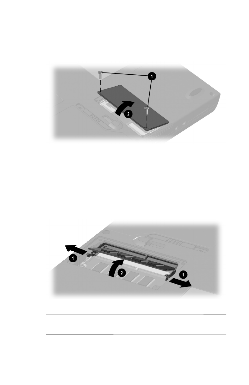
Hardware Upgrades
6. Remove the 2 screws securing the memory expansion
compartment cover
Opening the memory expansion compartment
7. Remove or insert the memory expansion board.
To remove a memory expansion board:
a. Pull away the retention clips on each side of the board 1.
(The board tilts upward
, then tilt up and remove the cover 2.
1
.)
2
b. Lift the edge of the memory expansion board, then gently
pull it out of the memory expansion slot.
Removing a memory expansion board
To protect a removed memory expansion board, place it in an
✎
electrostatic-safe container.
8–8 Hardware Guide
Page 94
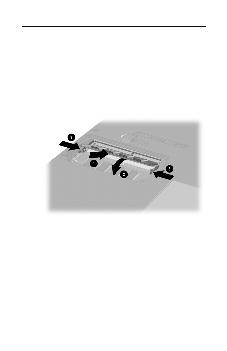
Hardware Upgrades
To insert a memory expansion board:
a. Align the keyed (notched) edge of the board with the
keyed area in an expansion slot
. (If no other memory
1
expansion board is in the memory expansion
compartment, insert the board into the lower slot.)
b. Press the board into the slot from a 45-degree angle until
it is seated, then push the board downward
retention clips snap into place
3
.
until the
2
Inserting a memory expansion board
Hardware Guide 8–9
Page 95
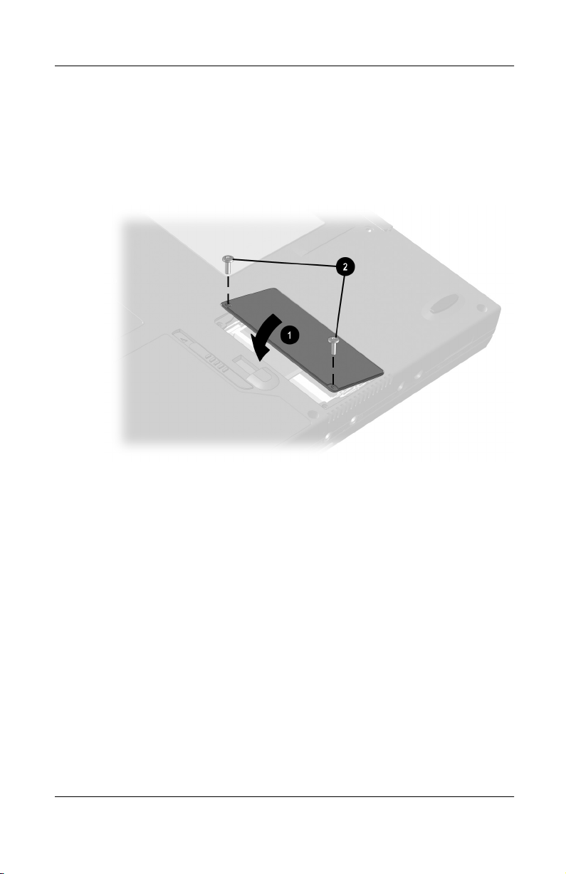
Hardware Upgrades
8. Align the tabs on the memory expansion compartment cover
with the cover slots on the computer, then tilt the cover
downward until it is seated
9. Replace the 2 screws securing the cover to the computer 2.
1
.
Closing the memory expansion compartment
8–10 Hardware Guide
Page 96

Specifications
This computer has been tested and found to comply with the
limits for a Class B digital device. For additional governmental
agency information refer on this CD to Regulatory and Safety
Notices.
Regulatory Agency Series Numbers
Regulatory agencies worldwide use agency series numbers for
product identification. Each approved product displays the
assigned agency series number. To ensure continued safe and
reliable operation, use the computer only with the products listed
below:
Product Agency Series Number
Computer PP2040
Battery pack PPP2041, PP2081
9
AC Adapter PPP005, PPP003
Docking bases PP1005, PP1006, PP1007
Automobile Adapter PPP007
Aircraft Adapter PPP004
Modem J07M040.00, U98M008
Modem/NIC U98M010
Hardware Guide 9–1
Page 97

Specifications
Computer Dimensions
Dimension U.S. Metric
Height 1.2 in. 3.1 cm
Width 12.0 in. 30.76 cm
Depth 9.8 in. 25.0 cm
Operating Environment
Factor U.S. Metric
Temperature
Operating 50° to 95° F 10° to 35° C
Nonoperating 14° to 140° F –10° to 60° C
Relative humidity (noncondensing)
Operating 10 to 90% 10 to 90%
Nonoperating 5 to 95% 5 to 95%
Maximum altitude (unpressurized)
Operating 10,000 ft 3,048 m
Nonoperating 30,000 ft 9,144 m
9–2 Hardware Guide
Page 98

Rated Input Power
Input Power Rating
Operating voltage 100–120/220–240 VAC RMS
Operating current 1.2/0.6 A RMS
Operating frequency range 50–60 Hz AC
When powered by a DC source 18.5V MAX
This product is designed for IT power systems in Norway with
✎
phase-to-phase voltage not exceeding 240 Vms.
Modem Specifications
Factor Specification
Temperatures
Operating 32° to 167° F (0° to 75° C)
Specifications
Storage –40° to 167° F (–40° to 75° C)
Relative Humidity (noncondensing)
Operating –10 to 90% (–10 to 90%)
Storage –5 to 95%@102° F (–5 to 95%@ 39° C)
Interfaces
Power
Requirements
Hardware Guide 9–3
Communications
connector
Telephone, central
office network
+3.3 volts ±5%, +3.3 vaux ±5%, +5 volts ±5%
Standard RJ-11
connector
Internal DAA
Page 99

Index
A
AC Adapter
connecting 1–2
function of 2–17
accelerator, graphics 3–12
adapter
for AC power cord. See AC
Adapter
for connecting AC Adapter to
electrical outlet (Japan only).
See Japan-specific outlet
adapter
for connecting computer to AC
power. See AC Adapter
for connecting modem
internationally. See
country-specific modem
adapter
for hard drive. See MultiBay
hard drive adapter (optional)
for keyboard/mouse (PS/2)
connector. See Y-adapter
(optional)
agency series numbers 9–1
Aircraft Power Adapter (optional)
2–13
altitude specifications 9–2
analog vs. digital telephone lines
7–2
application key 2–9
audio devices, connecting external
6–2, 7–1
Automobile Power
2–13
Adapter/Charger (optional)
B
battery bay
device supported 2–15
location number, in battery
3–11
charge displays
release latch 2–15
replacing battery pack in 4–3
battery light 1–3, 2–7
battery packs
calibrating 1–5
charging 4–1
discharging 4–1, 4–5
displaying charge status 3–11
4–2
location numbers, in battery
charge displays
MultiBay (optional), inserting
4–4
MultiBay (optional), removing
4–4
MultiBay (optional), replacing
with weight saver
MultiBay (optional), vs.
4–1
primary
new 4–2
primary, inserting 4–3
3–11
2–17, 5–10
,
Hardware Guide Index–1
Page 100

Index
primary, removing 4–3
recycling 4–5
replacing 4–2
storing 4–5
battery release latch 2–15
bay. See battery bay; external
diskette drive bay; hard drive
bay; MultiBay; MultiPort
BIOS (Basic Input/Output System)
3–12
Bluetooth 2–1, 3–8
brightness, screen 3–12
button(s)
dual pointing stick/TouchPad
3–3
Easy Access 3–16
PC Card 8–4
pointing-stick 3–1
sleep 2–9
suspend 1–5, 2–9
TouchPad 3–2
volume 2–12, 6–3
See also key; latch; switch
C
cable
AC Adapter 1–2
composite video 6–4
DC 2–13
modem 2–17, 7–2
modem vs. network 2–17
network 2–17, 7–3
security (optional) 7–11
See also power cord
cable lock, security (optional)
7–11
calibration of battery packs 1–5
camcorder (optional) 6–4, 7–1
cap, replacing pointing stick 2–18,
3–5
caps lock light 2–7
card and socket services, PC Card
8–2
CardWare (Windows NT 4.0) 8–2
CD
displaying contents of 5–15
inserting 5–12
removing (power available)
5–13
removing (power unavailable)
5–14
troubleshooting 5–16
CD drive (optional)
IDE drive light 2–7
inserting CD into 5–12
inserting into MultiBay 5–11
locations supported 5–1
removing CD from (power
available)
removing CD from (power
unavailable)
removing from MultiBay 5–9
See also drives
CD-RW. See CD
Certificate of Authenticity label
1–4
circuitry, noise suppression
on modem cable 7–2
on network cable 7–3
color television standards 6–5
Compaq Diagnostics 8–6
5–13
5–14
Index–2 Hardware Guide
 Loading...