

Page 1
Compaq Evo Desktop
D300 and D500
Small Form Factor
Celeron Models
Illustrated Parts Map
© 2001 Compaq Information Technologies Group, L.P.
Compaq, the Compaq logo, and Evo are trademarks of
Compaq Information Technologies Group, L.P.
Intel, Celeron, and Pentium are trademarks of Intel
Corporation in the United States and other countries.
All other product names mentioned herein may be
trademarks of their respective companies.
Compaq shall not be liable for technical or editorial errors
or omissions contained herein. The information in this
document is provided “as is” without warranty of any kind
and is subject to change without notice. The warranties for
Compaq products are set forth in the express limited
warranty statements accompanying such products. Nothing
herein should be construed as constituting an additional
warranty.
April 2002
b
Part Number 265669-003
Spare Part Number 265815-001
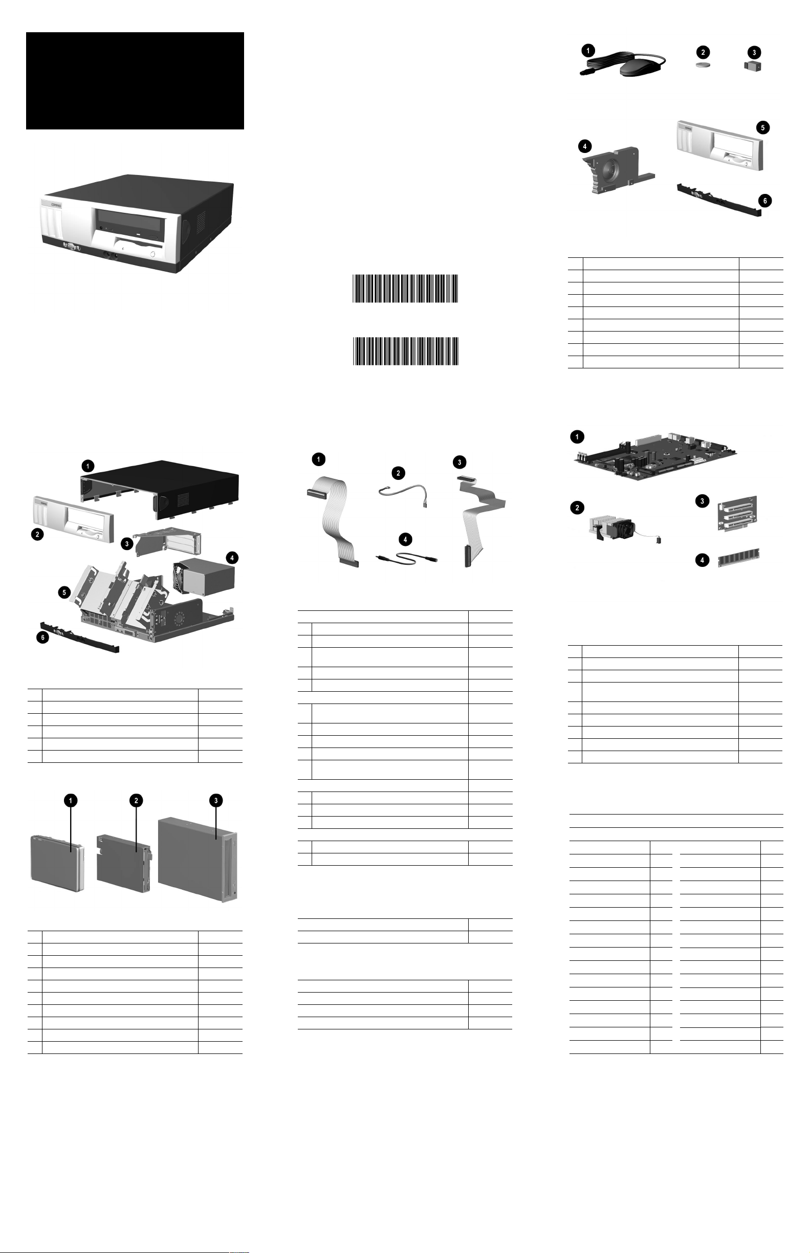
Miscellaneous Parts
1 Mouse, 2-button carbon 237241-001
2 Battery 153099-001
3 Solenoid, 2-coil 201485-001
4 Speaker 201273-001
5 Front bezel 257406-001
6 Front trim (below front bezel) (234257-001) 264699-001
* Lever, tilt/stop 222052-001
* Tamper resistant T-15 wrench 166527-001
* Tamper resistant T-15 bit (5 ea) 166527-002
*Not shown
System Unit
1 Computer cover not spared
2 Front bezel 257406-001
3 Expansion card cage not spared
4 Power supply, PFC, dual voltage 244165-001
5
Chassis assembly with drive cage not spared
6
Front trim (below front bezel) 264699-001
*Not shown
Mass Storage Devices
1
20-GB UATA (100/5400) Quiet hard drive 254451-001
*
20-GB UATA (100/7200) Quiet hard drive 180476-001
*
40-GB UATA (100/5400) Quiet hard drive 236921-001
*
40-GB UATA (100/7200) Quiet hard drive 202904-001
*
60-GB UATA (100/7200) hard drive 232022-001
2
Diskette drive, buttonless, carbon 237180-001
3
48X CD-ROM drive, carbon 232320-001
*
40X CD-RW drive, carbon 246691-001
*
16X DVD-ROM drive, carbon 232319-001
*
ZIP 250 drive, carbon 232317-001
*Not shown
Cables
Cable kit, includes: 201486-001
1
Diskette drive data cable, 8.5” (168999-001)
2
CD-ROM audio cable, 12” (387527-002)
3
Hard drive data cable, 18” (180950-016) (not this
product)
Solenoid cable (174311-001) (not this product)
*
*
CD-ROM data cable, 18” (108950-017)
Cable kit, includes: 192264-001
* Hard drive/CD-ROM data cable, 18” (108950-019)
(not this product)
* 40-Pin IDE data cable, 12.5” (105876-001)
* Audio cable, 21” (288489-002) (not this product)
* Audio cable, 21” (387527-001) (not this product)
* Hard drive/CD-ROM data cable, 9.75”
(108950-021) (not this product)
Cable kit, includes: 192263-001
* CD-ROM data cable, 18”, (108950-017)
* Audio cable, 12”, (387527-002)
4 Stereo cable extender, 100 mm 257081-001
Other cables
Hard drive cable, 12.75 “lg (108950-031) 266049-001
Solenoid cable (244168-002) 265954-001
*Not shown
Miscellaneous Plastics (not illustrated)
Bezel blank, carbon 257399-001
Foot, rubber (4 ea) (166939-004) 266050-001
Documentation and Packaging (not illustrated)
Service Reference Guide
Quick Troubleshooting Guide
Illustrated Parts Map
Return kit
259968-001
153837-001
265815-001
212545-001
Standard and Optional Boards
1
System board 239117-001
3 Riser board 244470-001
*
Intel Celeron 1.0 GHz processor with alcohol wipe 255433-001
2 Heatsink, 1.0 GHz and greater with thermal pad,
alcohol wipe, fan, and retaining clip
4 Memory Module, 64 MB, 133 MHz 170080-001
* Memory Module, 128 MB, 133 MHz 170081-001
* Memory Module, 256 MB, 133 MHz 192014-001
* Modem, 56K, PCI 239411-001
* NIC, 10/100 PCI, 3COM 253951-001
*Not shown
Keyboards (not illustrated)
Internet 164996-xxx
Basic Smart Card 240441-xxx
Arabic -171 International **
Belgian -181 Latin American Spanish -161
Brazilian Portuguese -201 Norwegian -191
BHCSY* -B41 Polish **
Czech -221 Portuguese -131
Danish -081 Russian -251
Dutch/Netherlands ** Slovakian -231
Finnish -351 Spanish -071
French -051 Swedish -101
French-Canadian -121 Swiss -111
German -041 Taiwanese -AB1
Greek -151 Thai -281
Hungarian -211 Turkish -141
Italian -061 United Kingdom -031
Japanese -191 U.S. -001
Korean (Hanguel) -AD1
*Bosnia-Herzegovina, Croatia, Slovenia, and Yugoslavia
**Use -B31 for 240441-xxx and use -002 for 164996-xxx
257400-001
Page 2
Keyboard Diagnostic LEDs
LED Color LED Activity State/Message
Num Lock Green Flashing (Beeps - 1S, 2L) Memory error
Caps Lock Green Flashing (Beeps - 1L, 2S) No video
Scroll Lock Green Flashing (Beeps - 2L, 1S) System board failure, prior to video
Num, Caps,
Scroll Lock
Num, Caps,
Scroll Lock
Num Lock Green On ROMPaq diskette not present, is bad, or drive
Caps Lock Green On Enter password.
Num, Caps,
Scroll Lock
* Insert valid ROMPaq diskette in drive A. Turn power switch off, then on to reflash ROM. If ROM flash is successful, all
three keyboard LEDs will light up, and you will hear a rising tone series of beeps. Remove diskette and turn power off,
then on to restart the computer. For more information about flashing the ROM, refer to the Troubleshooting guide.
Green Flash On-Off 2 times (Beeps -
Green On (Rising Tone) ROM reflashed successfully
Green Blink On in sequence, one at a
1L, 3S)
time - N, C, SL
Invalid system ROM detected. ROM forces
reflash.
not ready.*
Keyboard locked in network mode
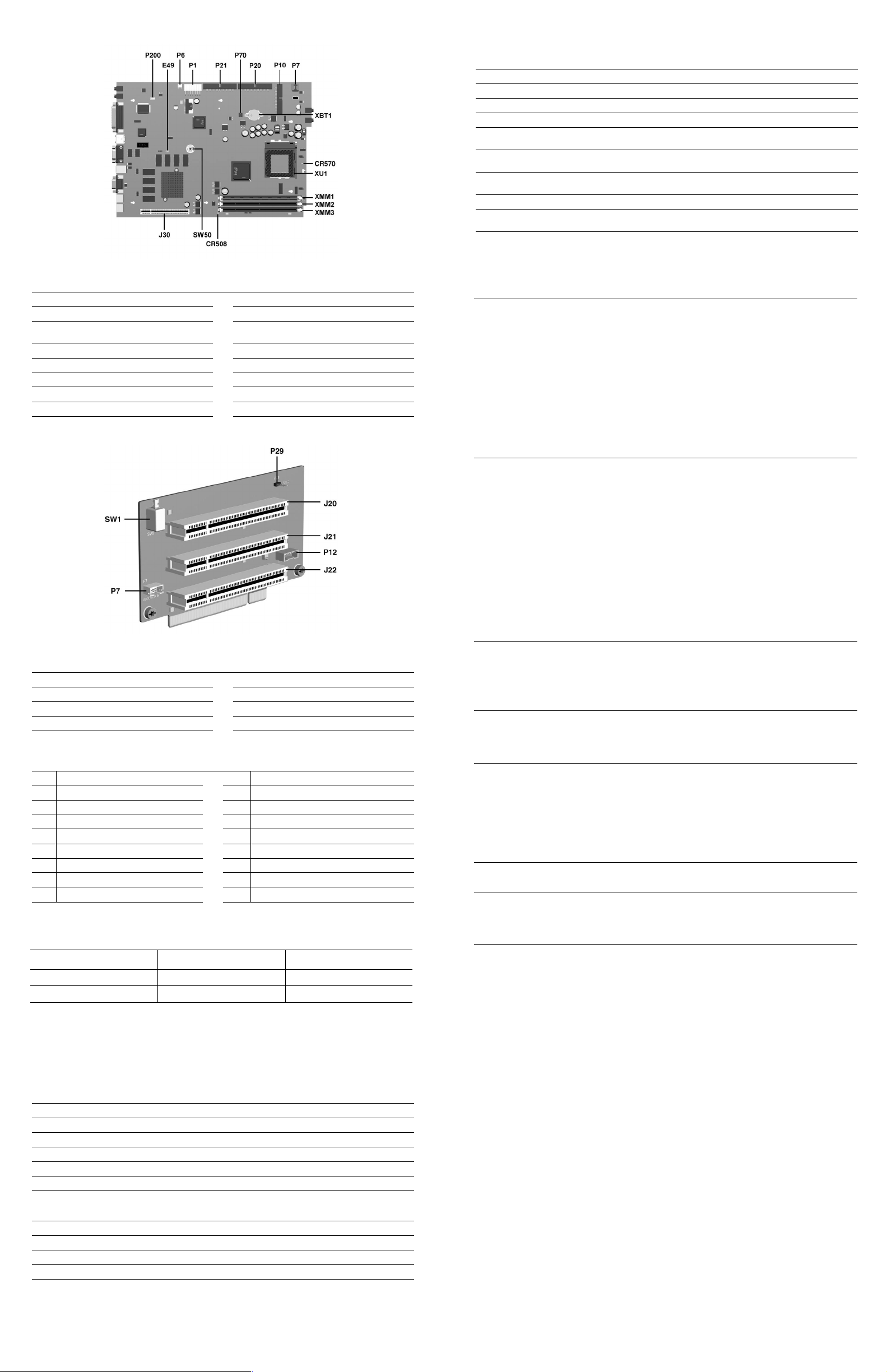
System Board Connectors and Jumpers (position of some untitled components may vary in location)
CR508 3.3V Aux LED P20 Primary IDE connector
CR570 5V Aux (ON)/PS_ON_(OFF) LED P21 Secondary IDE connector
E49 Password jumper (Installed = Enabled,
J30 Riser board P200 Hood lock solenoid connector
P1 Power supply connector SW50 Clear CMOS button
P6 Speaker connector XBT1 Battery
P7 CD-ROM audio XMM1-3 Memory sockets
P10 Diskette drive connector XU1 Processor socket
Removed = Cleared)
P70 CPU fan connector
Clearing CMOS*
The computer's configuration (CMOS) may occasionally be corrupted. If it is, it is necessary to clear the CMOS
memory using switch SW50.
To clear and reset the configuration, perform the following procedure:
1. Prepare the computer for disassembly.
CAUTION: The power cord must be disconnected from the power source before pushing the Clear CMOS
Ä
Button (NOTE: All LEDs on the board should be OFF). Failure to do so may damage the system board
2. Remove the access panel.
3. Press the CMOS button located on the system board and keep it depressed for 5 seconds.
4. Replace the access panel.
5. Turn the computer on and run F10 Computer Setup (delete-utility) to reconfigure the system.
*When the CMOS button is pushed or the jumper is removed, both the power-on password and the setup password
become invalid because both are stored in the configuration memory. You will need to reset the passwords.
Disabling or Clearing the Power-On and Setup Passwords*
1. Turn off the computer and any external devices, and disconnect the power cord from the power outlet.
2. Remove the access panel.
3. Locate the header and jumper labeled E49.
4. Remove the jumper from pins 1 and 2. Place the jumper over pin 2 only, in order to avoid losing it.
5. Replace the access panel.
6. Plug in the computer and turn on power. Allow the operating system to start.
NOTE: Placing the jumper on pin 2 clears the current passwords and disables the password features.
7. To re-enable the password features, repeat steps 1-3, then replace the jumper on pins 1 and 2.
8. Repeat steps 5-6, then establish new passwords.
Refer to the Computer Setup (F10 Setup) instructions to establish new passwords.
*When the CMOS button is pushed or the jumper is removed, both the power-on password and the setup password
become invalid because both are stored in the configuration memory. You will need to reset the passwords.
Riser Board Connectors and Jumpers
J20 PCI slot P12 NIC SOS connector
J21 PCI slot P29 SCSI LED connector
J22 PCI slot SW1 Security hood switch
P7 CD audio connector
System Hardware Interrupts
System Function IRQ System Function
IRQ
Timer Interrupt 8 Real-Time Clock
0
Keyboard 9 Unused
1
Interrupt Controller Cascade 10 Unused, available for PCI
2
Serial Port (COM B) 11 Unused, available for PCI
3
4
Serial Port (COM A) 12 Mouse
Unused, available for PCI 13 Coprocessor
5
Diskette Drive 14 ATA (IDE) Primary controller
6
Parallel Port (LPT 1) 15 ATA (IDE) Secondary controller
7
System Board Diagnostic Lights
Main Power Switch Status 3.3 V_Aux LED 5 V_Aux/PSON LED
2
OFF
3
ON
1. ON and OFF state of LEDs apply only to a good, working system board with AC power applied to the power supply.
2. Power LED on front of computer is OFF.
3. Power LED on front of computer is ON (Green).
4. 5V_Aux is ON.
5. PSON is active = power supply is turned ON.
1
ON
ON
ON
OFF
4
5
Computer Setup (F10) Utility Features (not all features may be available)
System Information
About
Set Time and date
File
Storage
Security
Power
Advanced
Note: See Computer Setup (F10) Utility Guide on the Documentation Library CD.
Save to Diskette
Restore From Diskette
Set defaults and Exit
Ignore Changes and Exit
Save Changes and Exit
Device Configuration
Options
IDE DPS Self-Test
Controller Order
SCSI Narrow Termination
Boot Order
Setup Password
Power-On Password
Password Options
Smart Cover
Smart Sensor
DriveLock
Master Boot Record Security
Save Master Boot Record
Restore Master Boot Record
Device Security
Network Service Boot
System IDs
Energy Saver
Timeouts
Energy Saver Options
Power-On Options
Onboard devices
PCI Devices
Bus Options
Devise Options
PCI VGA Configuration
Computer Diagnostic LEDs (on front of computer)
LED Color LED Activity State/Message
Power Green On (S0) Computer on
Power Green 1 blink every 1 second (S1) Normal Suspend Mode
Power Green 1 blink every 2 seconds (S3) Suspend to RAM
Power Green 1 blink every 4 seconds (S4) Suspend to Disk (if applicable)
Power Clear Off (S5) Computer off
Power Red 2 blinks 1 second apart, fol-
Power Red On CPU not installed
Power Red 1 blink every 1 second ROM error
Power Red 1 blink every 2 seconds Power supply crow bar
Hard Drive Green Blinking Hard drive activity
lowedby2-secondpauseRepeat
CPU thermal shutdown
 Loading...