

Page 1

HP P63x0/P65x0 Enterprise Virtual Array User Guide
Abstract
This document describes the hardware and general operation of the P63x0/P65x0 EVA.
HP Part Number: 5697-2486
Published: September 2013
Edition: 5
Page 2

© Copyright 2011, 2013 Hewlett-Packard Development Company, L.P.
The information contained herein is subject to change without notice. The only warranties for HP products and services are set forth in the express
warranty statements accompanying such products and services. Nothing herein should be construed as constituting an additional warranty. HP shall
not be liable for technical or editorial errors or omissions contained herein.
Warranty
To obtain a copy of the warranty for this product, see the warranty information website:
http://www.hp.com/go/storagewarranty
Acknowledgments
Microsoft® and Windows® are U.S. registered trademarks of Microsoft Corporation.
Java® and Oracle® are registered U.S. trademark of Oracle Corporation or its affiliates.
Intel® and Itanium® are registered trademarks of Intel Corporation or its subsidiaries in the United States and other countries.
Page 3

Contents
1 P63x0/P65x0 EVA hardware....................................................................13
SAS disk enclosures................................................................................................................13
Small Form Factor disk enclosure chassis...............................................................................13
Front view....................................................................................................................13
Rear view.....................................................................................................................14
Drive bay numbering.....................................................................................................14
Large Form Factor disk enclosure chassis...............................................................................14
Front view....................................................................................................................14
Rear view.....................................................................................................................15
Drive bay numbering.....................................................................................................15
Disk drives........................................................................................................................15
Disk drive LEDs.............................................................................................................15
Disk drive blanks...........................................................................................................16
Front status and UID module................................................................................................16
Front UID module LEDs...................................................................................................16
Unit identification (UID) button........................................................................................17
Power supply module..........................................................................................................17
Power supply LED..........................................................................................................17
Fan module.......................................................................................................................17
Fan module LED............................................................................................................18
I/O module......................................................................................................................18
I/O module LEDs..........................................................................................................19
Rear power and UID module...............................................................................................19
Rear power and UID module LEDs...................................................................................20
Unit identification (UID) button........................................................................................21
Power on/standby button...............................................................................................21
SAS cables.......................................................................................................................21
Controller enclosure................................................................................................................21
Controller status indicators..................................................................................................24
Controller status LEDs.....................................................................................................25
Power supply module..........................................................................................................26
Battery module..................................................................................................................27
Fan module.......................................................................................................................27
Management module.........................................................................................................28
iSCSI and iSCSI/FCoE recessed maintenance button..............................................................28
Reset the iSCSI or iSCSI/FCoE module and boot the primary image....................................29
Reset iSCSI or iSCSI/FCoE MGMT port IP address.............................................................29
Enable iSCSI or iSCSI/FCoE MGMT port DHCP address....................................................29
Reset the iSCSI or iSCSI/FCoE module to factory defaults...................................................29
HSV controller cabling............................................................................................................29
Storage system racks ..............................................................................................................30
Rack configurations............................................................................................................30
Power distribution units............................................................................................................31
PDU 1..............................................................................................................................31
PDU 2..............................................................................................................................31
PDMs...............................................................................................................................32
Rack AC power distribution.................................................................................................33
Moving and stabilizing a rack..................................................................................................33
2 P63x0/P65x0 EVA operation....................................................................36
Best practices.........................................................................................................................36
Operating tips and information................................................................................................36
Contents 3
Page 4

Reserving adequate free space............................................................................................36
Using SAS-midline disk drives..............................................................................................36
Failback preference setting for HSV controllers.......................................................................36
Changing virtual disk failover/failback setting..................................................................38
Implicit LUN transition.........................................................................................................38
Recovery CD.....................................................................................................................39
Adding disk drives to the storage system...............................................................................39
Handling fiber optic cables.................................................................................................39
Storage system shutdown and startup........................................................................................40
Powering on disk enclosures................................................................................................40
Powering off disk enclosures................................................................................................41
Shutting down the storage system from HP P6000 Command View...........................................41
Shutting down the storage system from the array controller......................................................41
Starting the storage system..................................................................................................41
Restarting the iSCSI or iSCSI/FCoE module ..........................................................................42
Using the management module................................................................................................43
Connecting to the management module................................................................................43
Connecting through a public network...............................................................................44
Connecting through a private network..............................................................................45
Accessing HP P6000 Command View on the management module..........................................45
Changing the host port default operating mode.....................................................................45
Saving storage system configuration data...................................................................................46
Saving or restoring the iSCSI or iSCSI/FCoE module configuration...........................................48
3 Configuring application servers..................................................................50
Overview..............................................................................................................................50
Clustering..............................................................................................................................50
Multipathing..........................................................................................................................50
Installing Fibre Channel adapters..............................................................................................50
Testing connections to the array................................................................................................51
Adding hosts..........................................................................................................................51
Creating and presenting virtual disks.........................................................................................52
Verifying virtual disk access from the host...................................................................................52
Configuring virtual disks from the host.......................................................................................52
HP-UX...................................................................................................................................52
Scanning the bus...............................................................................................................52
Creating volume groups on a virtual disk using vgcreate.........................................................53
IBM AIX................................................................................................................................54
Accessing IBM AIX utilities..................................................................................................54
Adding hosts.....................................................................................................................54
Creating and presenting virtual disks....................................................................................54
Verifying virtual disks from the host.......................................................................................54
Linux.....................................................................................................................................55
Driver failover mode...........................................................................................................55
Installing a QLogic driver....................................................................................................55
Upgrading Linux components..............................................................................................56
Upgrading qla2x00 RPMs..............................................................................................56
Detecting third-party storage...........................................................................................56
Compiling the driver for multiple kernels...........................................................................57
Uninstalling the Linux components........................................................................................57
Using the source RPM.........................................................................................................57
HBA drivers.......................................................................................................................58
Verifying virtual disks from the host.......................................................................................58
OpenVMS.............................................................................................................................58
4 Contents
Page 5

Updating the AlphaServer console code, Integrity Server console code, and Fibre Channel FCA
firmware...........................................................................................................................58
Verifying the Fibre Channel adapter software installation........................................................58
Console LUN ID and OS unit ID...........................................................................................59
Adding OpenVMS hosts.....................................................................................................59
Scanning the bus...............................................................................................................60
Configuring virtual disks from the OpenVMS host...................................................................61
Setting preferred paths.......................................................................................................61
Oracle Solaris........................................................................................................................61
Loading the operating system and software...........................................................................62
Configuring FCAs with the Oracle SAN driver stack...............................................................62
Configuring Emulex FCAs with the lpfc driver....................................................................62
Configuring QLogic FCAs with the qla2300 driver.............................................................64
Fabric setup and zoning.....................................................................................................65
Oracle StorEdge Traffic Manager (MPxIO)/Oracle Storage Multipathing..................................65
Configuring with Veritas Volume Manager............................................................................66
Configuring virtual disks from the host...................................................................................67
Verifying virtual disks from the host..................................................................................68
Labeling and partitioning the devices...............................................................................69
VMware................................................................................................................................70
Configuring the EVA with VMware host servers......................................................................70
Configuring an ESX server ..................................................................................................70
Setting the multipathing policy........................................................................................71
Verifying virtual disks from the host.......................................................................................73
HP P6000 EVA Software Plug-in for VMware VAAI.................................................................73
System prerequisites......................................................................................................73
Enabling vSphere Storage API for Array Integration (VAAI).................................................73
Installing the VAAI Plug-in...............................................................................................74
Installation overview.................................................................................................74
Installing the HP EVA VAAI Plug-in using ESX host console utilities...................................75
Installing the HP VAAI Plug-in using vCLI/vMA.............................................................76
Installing the VAAI Plug-in using VUM.........................................................................78
Uninstalling the VAAI Plug-in...........................................................................................80
Uninstalling VAAI Plug-in using the automated script (hpeva.pl).......................................80
Uninstalling VAAI Plug-in using vCLI/vMA (vihostupdate)...............................................80
Uninstalling VAAI Plug-in using VMware native tools (esxupdate)....................................81
4 Replacing array components......................................................................82
Customer self repair (CSR).......................................................................................................82
Parts-only warranty service..................................................................................................82
Best practices for replacing hardware components......................................................................82
Component replacement videos...........................................................................................82
Verifying component failure.................................................................................................82
Identifying the spare part....................................................................................................82
Replaceable parts...................................................................................................................83
Replacing the failed component................................................................................................85
Replacement instructions..........................................................................................................85
5 iSCSI or iSCSI/FCoE configuration rules and guidelines................................87
iSCSI or iSCSI/FCoE module rules and supported maximums ......................................................87
HP P6000 Command View and iSCSI or iSCSI/FCoE module management rules and guidelines......87
HP P63x0/P65x0 EVA storage system software..........................................................................87
Fibre Channel over Ethernet switch and fabric support.................................................................87
Operating system and multipath software support.......................................................................90
iSCSI initiator rules, guidelines, and support ..............................................................................91
General iSCSI initiator rules and guidelines ..........................................................................91
Contents 5
Page 6

Apple Mac OS X iSCSI initiator rules and guidelines..............................................................91
Microsoft Windows iSCSI Initiator rules and guidelines...........................................................91
Linux iSCSI Initiator rules and guidelines ..............................................................................92
Solaris iSCSI Initiator rules and guidelines.............................................................................92
VMware iSCSI Initiator rules and guidelines..........................................................................93
Supported IP network adapters ................................................................................................93
IP network requirements ..........................................................................................................93
Set up the iSCSI Initiator..........................................................................................................94
Windows..........................................................................................................................94
Multipathing.....................................................................................................................99
Installing the MPIO feature for Windows Server 2012...........................................................100
Installing the MPIO feature for Windows Server 2008..........................................................103
Installing the MPIO feature for Windows Server 2003..........................................................104
About Microsoft Windows Server 2003 scalable networking pack.........................................105
SNP setup with HP NC 3xxx GbE multifunction adapter...................................................105
iSCSI Initiator version 3.10 setup for Apple Mac OS X (single-path)........................................105
Set up the iSCSI Initiator for Apple Mac OS X.................................................................106
Storage setup for Apple Mac OS X................................................................................109
iSCSI Initiator setup for Linux.............................................................................................109
Installing and configuring the SUSE Linux Enterprise 10 iSCSI driver...................................109
Installing and configuring for Red Hat 5....................................................................111
Installing and configuring for Red Hat 4 and SUSE 9..................................................112
Installing the initiator for Red Hat 3 and SUSE 8.........................................................112
Assigning device names...............................................................................................112
Target bindings...........................................................................................................113
Mounting file systems...................................................................................................114
Unmounting file systems...............................................................................................114
Presenting EVA storage for Linux....................................................................................115
Setting up the iSCSI Initiator for VMware............................................................................115
Configuring multipath with the Solaris 10 iSCSI Initiator........................................................117
MPxIO overview.........................................................................................................118
Preparing the host system........................................................................................118
Enabling MPxIO for HP P63x0/P65x0 EVA...............................................................118
Enable iSCSI target discovery...................................................................................120
Modify target parameter MaxRecvDataSegLen...........................................................121
Monitor Multipath devices.......................................................................................122
Managing and Troubleshooting Solaris iSCSI Multipath devices...................................123
Configuring Microsoft MPIO iSCSI devices..........................................................................123
Load balancing features of Microsoft MPIO for iSCSI............................................................124
Microsoft MPIO with QLogic iSCSI HBA..............................................................................125
Installing the QLogic iSCSI HBA....................................................................................125
Installing the Microsoft iSCSI Initiator services and MPIO..................................................125
Configuring the QLogic iSCSI HBA................................................................................125
Adding targets to QLogic iSCSI Initiator.........................................................................126
Presenting LUNs to the QLogic iSCSI Initiator..................................................................127
Installing the HP MPIO Full Featured DSM for EVA...........................................................128
Microsoft Windows Cluster support....................................................................................129
Microsoft Cluster Server for Windows 2003...................................................................129
Requirements..............................................................................................................129
Setting the Persistent Reservation registry key...................................................................129
Microsoft Cluster Server for Windows 2008...................................................................130
Requirements.........................................................................................................130
Setting up authentication ..................................................................................................131
CHAP restrictions ............................................................................................................131
Microsoft Initiator CHAP secret restrictions ..........................................................................131
6 Contents
Page 7

Linux version...................................................................................................................132
ATTO Macintosh Chap restrictions .....................................................................................132
Recommended CHAP policies ...........................................................................................132
iSCSI session types ..........................................................................................................132
The iSCSI or iSCSI/FCoE controller CHAP modes ................................................................132
Enabling single–direction CHAP during discovery and normal session....................................132
Enabling CHAP for the iSCSI or iSCSI/FCoE module-discovered iSCSI initiator entry ................134
Enable CHAP for the Microsoft iSCSI Initiator.......................................................................135
Enable CHAP for the open-iscsi iSCSI Initiator .....................................................................135
Enabling single–direction CHAP during discovery and bi-directional CHAP during normal session
.....................................................................................................................................136
Enabling bi-directional CHAP during discovery and single–direction CHAP during normal
session...........................................................................................................................138
Enabling bi-directional CHAP during discovery and bi-directional CHAP during normal session...140
Enable CHAP for the open-iscsi iSCSI Initiator......................................................................142
iSCSI and FCoE thin provision handling..............................................................................144
6 Single path implementation.....................................................................149
Installation requirements........................................................................................................149
Recommended mitigations.....................................................................................................149
Supported configurations.......................................................................................................150
General configuration components.....................................................................................150
Connecting a single path HBA server to a switch in a fabric zone..........................................150
HP-UX configuration..............................................................................................................152
Requirements...................................................................................................................152
HBA configuration............................................................................................................152
Risks..............................................................................................................................152
Limitations.......................................................................................................................152
Windows Server 2003 (32-bit) ,Windows Server 2008 (32–bit) , and Windows Server 2012 (32–bit)
configurations......................................................................................................................153
Requirements...................................................................................................................153
HBA configuration............................................................................................................153
Risks..............................................................................................................................153
Limitations.......................................................................................................................154
Windows Server 2003 (64-bit) and Windows Server 2008 (64–bit) configurations.......................154
Requirements...................................................................................................................154
HBA configuration............................................................................................................154
Risks..............................................................................................................................155
Limitations.......................................................................................................................155
Oracle Solaris configuration...................................................................................................155
Requirements...................................................................................................................155
HBA configuration............................................................................................................156
Risks..............................................................................................................................156
Limitations.......................................................................................................................156
OpenVMS configuration........................................................................................................157
Requirements...................................................................................................................157
HBA configuration............................................................................................................157
Risks..............................................................................................................................157
Limitations.......................................................................................................................158
Xen configuration.................................................................................................................158
Requirements...................................................................................................................158
HBA configuration............................................................................................................158
Risks..............................................................................................................................159
Limitations.......................................................................................................................159
Linux (32-bit) configuration.....................................................................................................159
Contents 7
Page 8

Requirements...................................................................................................................159
HBA configuration............................................................................................................160
Risks..............................................................................................................................160
Limitations.......................................................................................................................160
Linux (Itanium) configuration...................................................................................................160
Requirements...................................................................................................................160
HBA configuration............................................................................................................161
Risks..............................................................................................................................161
Limitations.......................................................................................................................161
IBM AIX configuration...........................................................................................................162
Requirements...................................................................................................................162
HBA configuration............................................................................................................162
Risks..............................................................................................................................162
Limitations.......................................................................................................................162
VMware configuration...........................................................................................................163
Requirements...................................................................................................................163
HBA configuration............................................................................................................163
Risks..............................................................................................................................163
Limitations.......................................................................................................................164
Mac OS configuration...........................................................................................................164
Failure scenarios...................................................................................................................164
HP-UX.............................................................................................................................164
Windows Servers.............................................................................................................165
Oracle Solaris.................................................................................................................165
OpenVMS......................................................................................................................165
Linux..............................................................................................................................166
IBM AIX..........................................................................................................................167
VMware.........................................................................................................................167
Mac OS.........................................................................................................................168
7 Troubleshooting......................................................................................169
If the disk enclosure does not initialize.....................................................................................169
Diagnostic steps...................................................................................................................169
Is the enclosure front fault LED amber?................................................................................169
Is the enclosure rear fault LED amber?.................................................................................169
Is the power on/standby button LED amber?.......................................................................170
Is the power supply LED amber?........................................................................................170
Is the I/O module fault LED amber?....................................................................................170
Is the fan LED amber?.......................................................................................................171
Effects of a disk drive failure...................................................................................................171
Compromised fault tolerance.............................................................................................171
Factors to consider before replacing disk drives........................................................................171
Automatic data recovery (rebuild)...........................................................................................172
Time required for a rebuild................................................................................................172
Failure of another drive during rebuild................................................................................173
Handling disk drive failures...............................................................................................173
iSCSI module diagnostics and troubleshooting..........................................................................173
iSCSI and iSCSI/FCoE diagnostics.....................................................................................173
Locate the iSCSI or iSCSI/FCoE module.........................................................................174
iSCSI or iSCSI/FCoE module's log data.........................................................................175
iSCSI or iSCSI/FCoE module statistics............................................................................175
Troubleshoot using HP P6000 Command View................................................................175
Issues and solutions..........................................................................................................175
Issue: HP P6000 Command View does not discover the iSCSI or iSCSI/FCoE modules.........175
Issue: Initiator cannot login to iSCSI or iSCSI/FCoE module target.....................................176
8 Contents
Page 9

Issue: Initiator logs in to iSCSI or iSCSI/FCoE controller target but EVA assigned LUNs are not
appearing on the initiator............................................................................................176
Issue: EVA presented virtual disk is not seen by the initiator...............................................176
Issue: Windows initiators may display Reconnecting if NIC MTU changes after connection has
logged in...................................................................................................................177
Issue: When communication between HP P6000 Command View and iSCSI or iSCSI/FCoE
module is down, use following options:..........................................................................177
HP P6000 Command View issues and solutions...................................................................178
8 Error messages.......................................................................................180
9 Support and other resources....................................................................197
Contacting HP......................................................................................................................197
HP technical support........................................................................................................197
Subscription service..........................................................................................................197
Documentation feedback..................................................................................................197
Related documentation..........................................................................................................197
Documents......................................................................................................................197
Websites........................................................................................................................197
Typographic conventions.......................................................................................................198
Customer self repair..............................................................................................................198
Rack stability........................................................................................................................199
A Regulatory compliance notices.................................................................200
Regulatory compliance identification numbers..........................................................................200
Federal Communications Commission notice............................................................................200
FCC rating label..............................................................................................................200
Class A equipment......................................................................................................200
Class B equipment......................................................................................................200
Declaration of Conformity for products marked with the FCC logo, United States only...............201
Modification...................................................................................................................201
Cables...........................................................................................................................201
Canadian notice (Avis Canadien)...........................................................................................201
Class A equipment...........................................................................................................201
Class B equipment...........................................................................................................201
European Union notice..........................................................................................................201
Japanese notices..................................................................................................................202
Japanese VCCI-A notice....................................................................................................202
Japanese VCCI-B notice....................................................................................................202
Japanese VCCI marking...................................................................................................202
Japanese power cord statement.........................................................................................202
Korean notices.....................................................................................................................202
Class A equipment...........................................................................................................202
Class B equipment...........................................................................................................203
Taiwanese notices.................................................................................................................203
BSMI Class A notice.........................................................................................................203
Taiwan battery recycle statement........................................................................................203
Turkish recycling notice..........................................................................................................203
Vietnamese Information Technology and Communications compliance marking.............................203
Laser compliance notices.......................................................................................................204
English laser notice..........................................................................................................204
Dutch laser notice............................................................................................................204
French laser notice...........................................................................................................204
German laser notice.........................................................................................................205
Italian laser notice............................................................................................................205
Japanese laser notice.......................................................................................................205
Contents 9
Page 10

Spanish laser notice.........................................................................................................206
Recycling notices..................................................................................................................206
English recycling notice....................................................................................................206
Bulgarian recycling notice.................................................................................................206
Czech recycling notice......................................................................................................206
Danish recycling notice.....................................................................................................206
Dutch recycling notice.......................................................................................................207
Estonian recycling notice...................................................................................................207
Finnish recycling notice.....................................................................................................207
French recycling notice.....................................................................................................207
German recycling notice...................................................................................................207
Greek recycling notice......................................................................................................207
Hungarian recycling notice...............................................................................................208
Italian recycling notice......................................................................................................208
Latvian recycling notice.....................................................................................................208
Lithuanian recycling notice................................................................................................208
Polish recycling notice.......................................................................................................208
Portuguese recycling notice...............................................................................................209
Romanian recycling notice................................................................................................209
Slovak recycling notice.....................................................................................................209
Spanish recycling notice...................................................................................................209
Swedish recycling notice...................................................................................................209
Battery replacement notices...................................................................................................210
Dutch battery notice.........................................................................................................210
French battery notice........................................................................................................210
German battery notice......................................................................................................211
Italian battery notice........................................................................................................211
Japanese battery notice....................................................................................................212
Spanish battery notice......................................................................................................212
B Non-standard rack specifications..............................................................213
Internal component envelope..................................................................................................213
EIA310-D standards..............................................................................................................213
EVA cabinet measures and tolerances.....................................................................................213
Weights, dimensions and component CG measurements...........................................................214
Airflow and Recirculation.......................................................................................................214
Component Airflow Requirements.......................................................................................214
Rack Airflow Requirements................................................................................................214
Configuration Standards........................................................................................................214
UPS Selection.......................................................................................................................214
Shock and vibration specifications..........................................................................................215
C Command reference...............................................................................217
Command syntax..................................................................................................................217
Command line completion................................................................................................217
Authority requirements......................................................................................................217
Commands..........................................................................................................................217
Admin............................................................................................................................218
Beacon...........................................................................................................................218
Clear.............................................................................................................................218
Date..............................................................................................................................219
Exit................................................................................................................................219
FRU................................................................................................................................220
Help..............................................................................................................................220
History...........................................................................................................................222
Image............................................................................................................................222
10 Contents
Page 11

Initiator...........................................................................................................................223
Logout............................................................................................................................225
Lunmask.........................................................................................................................225
Passwd...........................................................................................................................228
Ping...............................................................................................................................229
Quit...............................................................................................................................230
Reboot...........................................................................................................................230
Reset..............................................................................................................................230
Save..............................................................................................................................231
Set.................................................................................................................................231
Set alias.........................................................................................................................232
Set CHAP.......................................................................................................................233
Set FC............................................................................................................................233
Set features.....................................................................................................................234
Set iSCSI........................................................................................................................235
Set iSNS.........................................................................................................................236
Set Mgmt........................................................................................................................236
Set NTP..........................................................................................................................237
Set properties..................................................................................................................237
Set SNMP.......................................................................................................................238
Set system.......................................................................................................................239
Set VPGroups..................................................................................................................239
Show.............................................................................................................................240
Show CHAP....................................................................................................................242
Show FC........................................................................................................................242
Show features..................................................................................................................244
Show initiators.................................................................................................................244
Show initiators LUN mask.................................................................................................246
Show iSCSI.....................................................................................................................247
Show iSNS.....................................................................................................................249
Show logs.......................................................................................................................249
Show LUNinfo.................................................................................................................250
Show LUNs.....................................................................................................................251
Show lunmask.................................................................................................................252
Show memory.................................................................................................................252
Show mgmt.....................................................................................................................253
Show NTP......................................................................................................................253
Show perf.......................................................................................................................254
Show presented targets.....................................................................................................255
Show properties..............................................................................................................258
Show SNMP...................................................................................................................259
Show stats......................................................................................................................259
Show system...................................................................................................................261
Show targets...................................................................................................................262
Show VPGroups...............................................................................................................262
Shutdown.......................................................................................................................263
Target............................................................................................................................263
Traceroute.......................................................................................................................264
D Using the iSCSI CLI.................................................................................265
Logging on to an iSCSI or iSCSI/FCoE module.........................................................................265
Understanding the guest account............................................................................................265
Working with iSCSI or iSCSI/FCoE module configurations.........................................................266
Modifying a configuration.................................................................................................267
Saving and restoring iSCSI or iSCSI/FCoE controller configurations........................................267
Contents 11
Page 12

Restoring iSCSI or iSCSI/FCoE module configuration and persistent data................................267
E Simple Network Management Protocol......................................................269
SNMP parameters................................................................................................................269
SNMP trap configuration parameters.......................................................................................269
Management Information Base ..............................................................................................270
Network port table...........................................................................................................270
FC port table...................................................................................................................272
Initiator object table.........................................................................................................273
LUN table.......................................................................................................................275
VP group table................................................................................................................277
Sensor table....................................................................................................................278
Notifications........................................................................................................................279
System information objects................................................................................................280
Notification objects..........................................................................................................280
Agent startup notification..................................................................................................281
Agent shutdown notification..............................................................................................281
Network port down notification..........................................................................................281
FC port down notification..................................................................................................281
Target device discovery....................................................................................................282
Target presentation (mapping)...........................................................................................282
VP group notification........................................................................................................282
Sensor notification...........................................................................................................283
Generic notification..........................................................................................................283
F iSCSI and iSCSI/FCoE module log messages.............................................284
Glossary..................................................................................................298
Index.......................................................................................................311
12 Contents
Page 13

1 P63x0/P65x0 EVA hardware
The P63x0/P65x0 EVA contains the following components:
• EVA controller enclosure — Contains HSV controllers, power supplies, cache batteries, and
fans. Available in FC and iSCSI options
NOTE: Compared to older models, the HP P6350 and P6550 employ newer batteries and
a performance enhanced management module. They require XCS Version 11000000 or later
on the P6350 and P6550 and HP P6000 Command View Version 10.1 or later on the
management module. The P6300 and P6350 use the HSV340 controller while the P6500
and P6550 use the HSV360 controller.
• SAS disk enclosure — Contains disk drives, power supplies, fans, midplane, and I/O modules.
• Y-cables — Provides dual-port connectivity to the EVA controller.
• Rack — Several free standing racks are available.
SAS disk enclosures
6 Gb SAS disk enclosures are available in two models:
• Small Form Factor (SFF): Supports 25 SFF (2.5 inch) disk drives
• Large Form Factor (LFF): Supports 12 LFF (3.5 inch) disk drives
• The SFF model is M6625; the LFF model is M6612.
Small Form Factor disk enclosure chassis
Front view
3. UID push button and LED1. Rack-mounting thumbscrew
4. Enclosure status LEDs2. Disk drive in bay 9
SAS disk enclosures 13
Page 14

Rear view
Drive bay numbering
Disk drives mount in bays on the front of the enclosure. Bays are numbered sequentially from top
to bottom and left to right. Bay numbers are indicated on the left side of each drive bay.
7. UID push button and LED4. I/O module A1. Power supply 1
8. Enclosure status LEDs5. I/O module B2. Power supply 2
9. Power push button and LED6. Fan 23. Fan 1
Large Form Factor disk enclosure chassis
Front view
3. UID push button and LED1. Rack-mounting thumbscrew
4. Enclosure status LEDs2. Disk drive in bay 6
14 P63x0/P65x0 EVA hardware
Page 15

Rear view
Drive bay numbering
Disk drives mount in bays on the front of the enclosure. Bays are numbered sequentially from top
to bottom and left to right. A drive-bay legend is included on the left bezel.
7. UID push button and LED4. I/O module A1. Power supply 1
8. Enclosure status LEDs5. I/O module B2. Power supply 2
9. Power push button and LED6. Fan 23. Fan 1
Disk drives
Disk drives are hot-pluggable. A variety of disk drive models are supported for use.
Disk drive LEDs
Two LEDs indicate drive status.
NOTE: The following image shows a Small Form Factor (SFF) disk drive. LED patterns are the
same for SFF and LFF disk drives.
SAS disk enclosures 15
Page 16

DescriptionLED statusLED colorLED
Locate driveSlow blinking (0.5 Hz)Blue1. Locate/Fault
Drive faultSolidAmber
Disk drive blanks
To maintain the proper enclosure air flow, a disk drive or a disk drive blank must be installed in
each drive bay. The disk drive blank maintains proper airflow within the disk enclosure.
Front status and UID module
The front status and UID module includes status LEDs and a unit identification (UID) button.
Front UID module LEDs
Blinking (1 Hz)Green2. Status
Drive is spinning up or down
and is not ready
Drive activityFast blinking (4 Hz)
Ready for activitySolid
16 P63x0/P65x0 EVA hardware
Blinking
Blinking
Solid
Blinking
Solid
DescriptionLED statusLED colorLED iconLED
No powerOffGreen1. Health
Enclosure is starting up and not ready,
performing POST
Normal, power is onSolid
Normal, no fault conditionsOffAmber2. Fault
A fault of lesser importance was detected in the
enclosure chassis or modules
A fault of greater importance was detected in
the enclosure chassis or modules
Not being identified or power is offOffBlue3. UID
Unit is being identified from the management
utility
Unit is being identified from the UID button
being pushed
Page 17

Unit identification (UID) button
The unit identification (UID) button helps locate an enclosure and its components. When the UID
button is activated, the UID on the front and rear of the enclosure are illuminated.
NOTE: A remote session from the management utility can also illuminate the UID.
• To turn on the UID light, press the UID button. The UID light on the front and the rear of the
enclosure will illuminate solid blue. (The UID on cascaded storage enclosures are not
illuminated.)
• To turn off an illuminated UID light, press the UID button. The UID light on the front and the
rear of the enclosure will turn off.
Power supply module
Two power supplies provide the necessary operating voltages to all controller enclosure components.
If one power supply fails, the remaining power supply is capable of operating the enclosure.
(Replace any failed component as soon as possible.)
NOTE: If one of the two power supply modules fails, it can be hot-replaced.
Power supply LED
One LED provides module status information.
Fan module
Fan modules provide cooling necessary to maintain proper operating temperature within the disk
enclosure. If one fan fails, the remaining fan is capable of cooling the enclosure. (Replace any
failed component as soon as possible.)
NOTE: If one of the two fan modules fail, it can be hot-replaced.
DescriptionLED status
No powerOff
Normal, no fault conditionsOn
SAS disk enclosures 17
Page 18

Fan module LED
One bi-color LED provides module status information.
DescriptionLED statusLED color
No powerOffOff
The module is being identifiedBlinkingGreen
I/O module
The I/O module provides the interface between the disk enclosure and the host.
Each I/O module has two ports that can transmit and receive data for bidirectional operation.
Normal, no fault conditionsSolid
Fault conditions detectedBlinkingAmber
Problems detecting the moduleSolid
3. SAS Port 2
18 P63x0/P65x0 EVA hardware
4. Double 7–segment display1. Manufacturing diagnostic port
5. I/O module LEDs2. SAS Port 1
Page 19

I/O module LEDs
LEDs on the I/O module provide status information about each I/O port and the entire module.
NOTE: The following image illustrates LEDs on the Small Form Factor I/O module.
DescriptionLED statusLED colorLED iconLED
display
OffGreenn/a1. SAS Port Link
Blinking
Solid
Offn/an/a3. 7–segment
Solid
Blinking
No cable, no power, or port not
connected
The port is being identified by an
application client
Healthy, active linkSolid
Normal, no errors detectedOffAmbern/a2. SAS Port Error
Error detected by application clientBlinking
Error, fault conditions detected on
the port by the I/O module
No cable, no power, enclosure not
detected
The enclosure box numberNumber
Not being identified or no powerOffBlue4. UID
Module is being identified, from
the management utility
No power or firmware malfunctionOffGreen5. Health
Enclosure is starting up and not
ready, performing POST
Normal, power is onSolid
Rear power and UID module
The rear power and UID module includes status LEDs, a unit identification (UID) button, and the
power on/standby button.
Solid
Normal, no fault conditionsOffAmber6. Fault
A fault of lesser importanceBlinking
A fault of greater importance, I/O
failed to start
SAS disk enclosures 19
Page 20

Rear power and UID module LEDs
DescriptionStatusLED colorLED iconLED
OffBlue1. UID
On
Blinking
Not being identified or no
power
Unit is being identified, either
from the UID button being
pushed or from the
management utility
No powerOffGreen2. Health
Enclosure is starting up and
not ready, performing POST
Normal, power is onSolid
Normal, no fault conditionsOffAmber3. Fault
A fault of lesser importanceBlinking
A fault of greater importanceSolid
Power is onSolidGreen4. On/Standby
Standby powerSolidAmber
20 P63x0/P65x0 EVA hardware
Page 21

Unit identification (UID) button
The unit identification (UID) button helps locate an enclosure and its components. When the UID
button is activated, the UID on the front and rear of the enclosure are illuminated.
NOTE: A remote session from the management utility can also illuminate the UID.
• To turn on the UID light, press the UID button. The UID light on the front and the rear of the
enclosure will illuminate solid blue. (The UID on cascaded storage enclosures are not
illuminated.)
• To turn off an illuminated UID light, press the UID button. The UID light on the front and the
rear of the enclosure will turn off.
Power on/standby button
The power on/standby button applies either full or partial power to the enclosure chassis.
• To initially power on the enclosure, press and hold the on/standby button for a few seconds,
until the LEDs begin to illuminate.
• To place an enclosure in standby, press and hold the on standby button for a few seconds,
until the on/standby LED changes to amber.
NOTE: System power to the disk enclosure does not completely shut off with the power on/standby
button. The standby position removes power from most of the electronics and components, but
portions of the power supply and some internal circuitry remain active. To completely remove
power from the system, disconnect all power cords from the device.
SAS cables
These disk enclosures use cables with mini-SAS connectors for connections to the controller and
cascaded disk enclosures.
Controller enclosure
For both the P63x0 EVA and P65x0 EVA, a single enclosure contains a management module and
two controllers. Two interconnected controllers ensure that the failure of a controller component
does not disable the system. One controller can fully support an entire system until the defective
controller, or controller component, is repaired. The controllers have an 8 Gb host port capability.
The P63x0 and P65x0 EVA controllers are available in FC, FC-iSCSI, and iSCSI/FCoE versions.
The controller models are HSV340 (for the P63x0) and HSV360 (for the P65x0).
Figure 1 (page 22) shows the bezel of the controller enclosure. Figure 2 (page 22) shows the front
of the controller enclosure with the bezel removed.
Controller enclosure 21
Page 22

Figure 1 Controller enclosure (front bezel)
2. Front UID push button1. Enclosure status LEDs
Figure 2 Controller enclosure (front view with bezel removed)
8. Fan 1 normal operation LED1. Rack-mounting thumbscrew
9. Fan 1 fault LED2. Enclosure product number (PN) and serial number
10. Fan 23. World Wide Number (WWN)
11. Battery 24. Battery 1
12. Enclosure status LEDs5. Battery normal operation LED
13. Front UID push button6. Battery fault LED
7. Fan 1
Each P63x0 controller contains two SAS data ports. Each P65x0 controller contains four SAS data
ports (made possible using Y-cables—one cable with two outputs). For both the P63x0 and P65x0
EVA, the FC controller adds four 8 Gb FC ports (Figure 3 (page 23)); the FC-iSCSI controller adds
two 8 Gb FC ports and four 1 GbE iSCSI ports (Figure 4 (page 23)); and the iSCSI/FCoE controller
adds two 8 Gb FC ports and two10 GbE iSCSI/FCoE ports (Figure 5 (page 24)).
22 P63x0/P65x0 EVA hardware
Page 23

Figure 3 P6000 EVA FC controller enclosure (rear view)
9. Enclosure power push button1. Power supply 1
10. Power supply 22. Controller 1
11. DP-A and DP-B, connection to back end (storage)3. Management module status LEDs
12. FP1 and FP2, connection to front end (host or SAN)4. Ethernet port
13. FP3 and FP4, connection to front end (host or SAN)5. Management module
14. Manufacturing diagnostic port6. Controller 2
15. Controller status and fault LEDs7. Rear UID push button
8. Enclosure status LEDs
Figure 4 P6000 EVA FC-iSCSI controller enclosure (rear view)
10. Power supply 21. Power supply 1
11. Serial port2. Controller 1
12. SW Management port3. Management module status LEDs
13. DP-A and DP-B, connection to back-end (storage)4. Ethernet port
14. 1GbE ports 1–45. Management module
15. FP3 and FP4, connection to front end (host or SAN)6. Controller 2
16. Manufacturing diagnostic port7. Rear UID push button
17. Controller status and fault LEDs8. Enclosure status LEDs
18. iSCSI module recessed maintenance button9. Enclosure power push button
Controller enclosure 23
Page 24

Figure 5 P6000 EVA iSCSI/FCoE controller enclosure (rear view)
10. Power supply 21. Power supply 1
11. 10GbE ports 1–22. Controller 1
12. DP-A and DP-B, connection to back-end (storage)3. Management module status LEDs
13. Serial port4. Ethernet port
14. FP3 and FP4, connection to front end (host or SAN)5. Management module
15. SW Management port6. Controller 2
16. Manufacturing diagnostic port7. Rear UID push button
17. Controller status and fault LEDs8. Enclosure status LEDs
18. iSCSI/FCoE recessed maintenance button9. Enclosure power push button
NOTE: The only difference between the P63x0 and P65x0 controllers is the number indicated
below the SAS data ports (DP-A and DP-B). On the P63x0, 1 is displayed (Figure 6 (page 24)).
On the P65x0, 1 | 2is displayed (Figure 7 (page 24)).
Figure 6 P63x0 data port numbering
Figure 7 P65x0 data port numbering
Controller status indicators
The status indicators display the operational status of the controller. The function of each indicator
is described in Table 3 (page 25). During initial setup, the status indicators might not be fully
operational.
Each port on the rear of the controller has an associated status indicator located directly above it.
Table 1 (page 25) lists the port and its status description for the HSV340. Table 2 (page 25) lists
the port and its status descriptions for the HSV340 FC-iSCSI.
24 P63x0/P65x0 EVA hardware
Page 25

Table 1 HSV340/360 controller port status indicators
DescriptionPort
Fibre Channel host ports
Fibre Channel device ports
1
On copper Fibre Channel cables, the SFP is integrated into the cable connector.
• Green — Normal operation
• Amber — No signal detected
• Off — No SFP1detected or the Direct Connect HP P6000 Control Panel
setting is incorrect
• Green — Normal operation
• Amber — No signal detected or the controller has failed the port
• Off — No SFP1detected
Table 2 HSV340/360 FC-iSCSI controller port status indicators
DescriptionPort
Fibre Channel switch ports
Fibre Channel device ports
1
On copper Fibre Channel cables, the SFP is integrated into the cable connector.
• Green on — Normal operation or loopback port
• Green flashing — Normal online I/O activity
• Amber on — Faulted port, disabled due to diagnostics or Portdisable
command
• Amber flashing — Port with no synchronization, receiving light but not yet
online or segmented port
• Off — No SFP1, no cable, no license detected.
• Green — Normal operation
• Amber — No signal detected or the controller has failed the port
• Off — No SFP1detected
Controller status LEDs
Figure 8 (page 25) shows the location of the controller status LEDs; Table 3 (page 25) describes
them.
NOTE: Figure 8 (page 25) shows an FC-iSCSI controller, however the LEDs for the FC, FC-iSCSI,
and iSCSI/FCoE controllers are identical, unless specifically noted.
Figure 8 Controller status LEDs
Table 3 Controller status LEDs
1
2
IndicationLEDItem
Blue LED identifies a specific controller within the enclosure or
identifies the FC-iSCSI or iSCSI/FCoE module within the controller.
Green LED indicates controller health. LED flashes green during
boot and becomes solid green after boot.
Controller enclosure 25
Page 26

Table 3 Controller status LEDs (continued)
IndicationLEDItem
3
MEZZ4
5
6
Flashing amber indicates a controller termination, or the system
is inoperative and attention is required. Solid amber indicates that
the controller cannot reboot, and that the controller should be
replaced. If both the solid amber and solid blue LEDs are lit, the
controller has completed a warm removal procedure, and can be
safely swapped.
Only used on the FC-iSCSI and iSCSI/FCoE controllers (not on
the FC controller).
Amber LED indicates the FC-iSCSI or iSCSI/FCoE module status
that is communicated to the array controller.
Slow flashing amber LED indicates an IP address conflict on the
management port.
Solid amber indicates an FC-iSCSI or iSCSI/FCoE module critical
error, or shutdown.
Green LED indicates write-back cache status. Slow flashing green
LED indicates standby power. Solid green LED indicates cache is
good with normal AC power applied.
Amber LED indicates DIMM status. The LED is off when DIMM
status is good. Slow flashing amber indicates DIMMs are being
powered by battery (during AC power loss). Flashing amber with
the chassis powered up indicates a degraded battery. Solid amber
with the chassis powered up indicates a failed battery.
Power supply module
Two power supplies provide the necessary operating voltages to all controller enclosure components.
If one power supply fails, the remaining power supply is capable of operating the enclosure.
(Replace any failed component as soon as possible.)
NOTE: If one of the two power supply modules fails, it can be hot-replaced.
Figure 9 Power supply
3. Latch
4. Status indicator (dual-color: amber and green)1. Power supply
5. Handle2. AC input connector
26 P63x0/P65x0 EVA hardware
Page 27
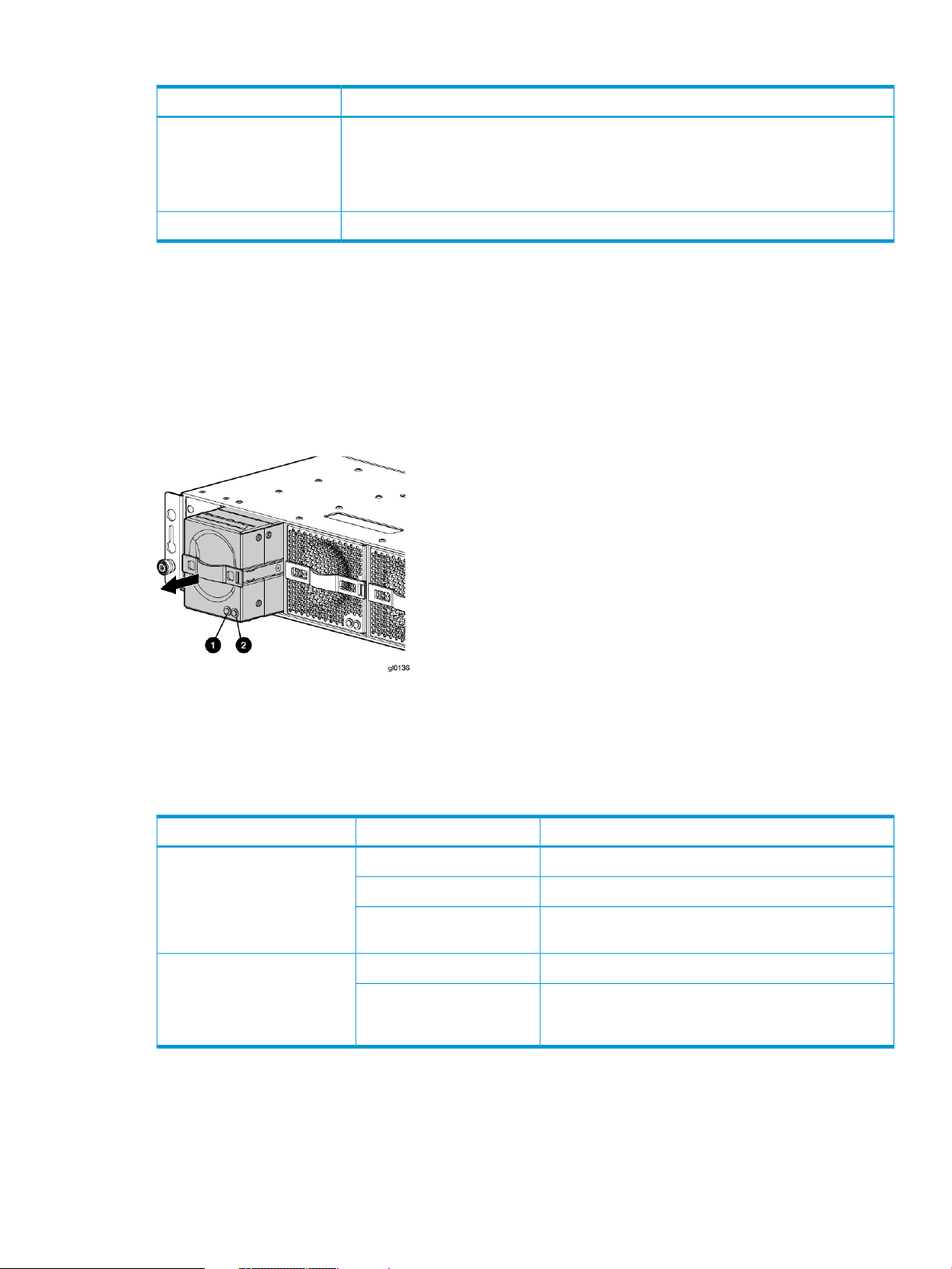
Table 4 Power supply LED status
DescriptionLED color
Amber
Battery module
Battery modules provide power to the controllers in the enclosure.
Figure 10 Battery module pulled out
• The power supply is powered up but not providing output power.
• The power supply is plugged into a running chassis, but is not receiving AC input
power (the fan and LED on the supply receive power from the other power supply in
this situation).
Normal, no fault conditionsGreen
Each battery module provides power to the controller directly across from it in the enclosure.
Table 5 Battery status indicators
Fan module
Fan modules provide the cooling necessary to maintain the proper operating temperature within
the controller enclosure. If one fan fails, the remaining fan is capable of cooling the enclosure.
Off
Blinking amber
2. Amber—Fault LED1. Green—Normal operation LED
DescriptionFault indicatorStatus indicator
Normal operation.Solid greenOn left—Green
Maintenance in progress.Blinking
Amber is on or blinking, or the enclosure is powered
down.
Battery failure; no cache hold-up. Green will be off.Solid amberOn right—Amber
Battery degraded; replace soon. Green will be off.
(Green and amber are not on simultaneously except for
a few seconds after power-up.)
Controller enclosure 27
Page 28

Figure 11 Fan module pulled out
Table 6 Fan status indicators
2. Amber—Fan fault LED1. Green—Fan normal operation LED
DescriptionFault indicatorStatus indicator
Normal operation.Solid greenOn left—Green
Maintenance in progress.Blinking
Off
OnOn right—Amber
Amber is on or blinking, or the enclosure is powered
down.
Fan failure. Green will be off. (Green and amber are
not on simultaneously except for a few seconds after
power-up.)
Management module
The HP P6000 Control Panel provides a direct interface to the management module within each
controller. From the HP P6000 Control Panel you can display storage system status and configuration
information, shut down the storage system, and manage the password. For tasks to perform with
the HP P6000 Control Panel, see the HP P6000 Control Panel online help.
The HP P6000 Control Panel provides two levels of administrator access and an interface for
software updates to the management module. For additional details about the HP P6000 Control
Panel, see the HP P6000 Control Panel online help.
NOTE: The HP P6350 and P6550 employ a performance-enhanced management module as
well as new batteries. This requires HP P6000 Command View 10.1 or later on the management
module and XCS 11000000 or later on the P6350 and P6550.
iSCSI and iSCSI/FCoE recessed maintenance button
The iSCSI and iSCSI/FCoE recessed maintenance button is the only manual user-accessible control
for the module. It is used to reset or to recover a module. This maintenance button is a multifunction
momentary switch and provides the following functions, each of which causes a reboot that
completes in less than one minute:
• Reset the iSCSI or iSCSI/FCoE module and boot the primary image
• Reset the iSCSI or iSCSI/FCoE MGMT port IP address
• Enable iSCSI or iSCSI/FCoE MGMT port DHCP address
• Reset the iSCSI or iSCSI/FCoE module to factory defaults
28 P63x0/P65x0 EVA hardware
Page 29

Reset the iSCSI or iSCSI/FCoE module and boot the primary image
Use a pointed nonmetallic tool to briefly press the maintenance button for a duration of two seconds
and release it. The iSCSI or iSCSI/FCoE module responds as follows:
1. The amber MEZZ status LED illuminates once.
NOTE: Holding the maintenance button for more than two seconds but less than six seconds
or until the MEZZ status LED illuminates twice, boots a secondary image, and is not
recommended for field use.
2. After approximately two seconds, the power-on self-test begins, and the MEZZ status LED is
turned off.
3. When the power-on self test is complete, the MEZZ status LED illuminates and flashes once
per second.
Reset iSCSI or iSCSI/FCoE MGMT port IP address
Reset and restore the MGMT port IP address to the default of 192.168.0.76 or 192.168.0.82
depending on the controller 1 or 2 position.
NOTE: Setting the IP address by this method is not persistent. To make the change persistent,
use the command line interface (CLI).
1. Use a pointed nonmetallic tool to briefly press the maintenance button. Release the button
after six seconds and observe six extended flashes of the MEZZ status LED.
2. The iSCSI or iSCSI/FCoE module boots and sets the MGMT port to IP address 192.168.0.76
or 192.168.0.82 depending on the controller 1 or 2 position.
Enable iSCSI or iSCSI/FCoE MGMT port DHCP address
Resets the iSCSI or iSCSI/FCoE module and configure the MGMT port to use DHCP to access its
IP address. Enabling DHCP by this method is not persistent. To make the change persistent, use
the CLI .
1. Use a pointed nonmetallic tool to briefly press the maintenance button. Release the button
after seven seconds and observe seven extended flashes of the MEZZ status LED.
2. The iSCSI or iSCSI/FCoE module boots and configures the MGMT port for DHCP.
Reset the iSCSI or iSCSI/FCoE module to factory defaults
This resets the iSCSI or iSCSI/FCoE module and restores it to the factory default configuration,
with reset passwords, MGMT port IP address set to either 192.168.0.76 or 192.168.0.82
depending on the controller 1 or 2 position, Disables iSCSI ports with no IP address, erases
presentations, and erases discovered initiators and targets).
1. Use a pointed nonmetallic tool to press the maintenance button. Release the button after twenty
seconds and observe twenty extended flashes of the MEZZ status LED.
2. The iSCSI or iSCSI/FCoE module boots and is restored to factory defaults.
HSV controller cabling
All data cables and power cables attach to the rear of the controller. Adjacent to each data
connector is a two-colored link status indicator. Table 1 (page 25) identifies the status conditions
presented by these indicators.
NOTE: These indicators do not indicate whether there is communication on the link, only whether
the link can transmit and receive data.
The data connections are the interfaces to the disk drive enclosures, the other controller, and the
fabric. Fiber optic cables link the controllers to the fabric, and, if an expansion cabinet is part of
the configuration, link the expansion cabinet drive enclosures to the loops in the main cabinet.
HSV controller cabling 29
Page 30

Y-cables (Figure 12 (page 30)) are used to connect the P6500 EVA and enable each controller
data port to act as two ports.
Figure 12 P6500 Y-cable
Storage system racks
All storage system components are mounted in a rack. Each configuration includes one controller
enclosure holding both controllers (the controller pair) and the disk enclosures. Each controller pair
and all associated disk enclosures form a single storage system.
The rack provides the capability for mounting standard 483 mm (19 in) wide controller and disk
enclosures.
NOTE: Racks and rack-mountable components are typically described using “U” measurements.
“U” measurements are used to designate panel or enclosure heights. The “U” measurement is a
standard of 41mm (1.6 in).
The racks provide the following:
• Unique frame and rail design—Allows fast assembly, easy mounting, and outstanding structural
integrity.
• Thermal integrity—Front-to-back natural convection cooling is greatly enhanced by the innovative
multi-angled design of the front door.
• Security provisions—The front and rear door are lockable, which prevents unauthorized entry.
• Flexibility—Provides easy access to hardware components for operation monitoring.
• Custom expandability—Several options allow for quick and easy expansion of the racks to
create a custom solution.
2. Port number label1. Pull tab (may also be a release bar)
Rack configurations
The standard rack for the P63x0/P65x0 EVA is the 42U HP 10000 Intelligent Series rack. The
P63x0/P65x0 EVA is also supported with 22U, 36U, 42U 5642, and 47U racks. The 42U 5642
is a field-installed option. The 47U rack must be assembled on site because the cabinet height
creates shipping difficulties.
For more information on HP rack offerings for the P63x0/P65x0 EVA see:
30 P63x0/P65x0 EVA hardware
Page 31

http://h18004.www1.hp.com/products/servers/proliantstorage/racks/index.html
Power distribution units
AC power is distributed to the rack through a dual Power Distribution Unit (PDU) assembly mounted
at the bottom rear of the rack (modular PDU) or on the rack (monitored PDU). The modular PDU
may be mounted back-to-back either vertically (AC receptacles facing down and circuit breaker
switches facing up) or horizontally (AC receptacles facing front and circuit breaker switches facing
rear). For information about PDU support with the P63x0/P65x0 EVA, see the HP P6300/P6500
Enterprise Virtual Arrays QuickSpecs. For details and specifications about specific PDU models,
see the HP Power Distribution Units website:
http://h18004.www1.hp.com/products/servers/proliantstorage/power-protection/pdu.html
The standard power configuration for any HP Enterprise Virtual Array rack is the fully redundant
configuration. Implementing this configuration requires:
• Two separate circuit breaker-protected, 30-A site power sources with a compatible wall
receptacle.
• One dual PDU assembly. Each PDU connects to a different wall receptacle.
• Four to eight (depending on the rack) Power Distribution Modules (PDMs) per rack. All PDMs
are located (side by side in pairs) on the left side of the rack. Each set of PDMs connects to
a different PDU.
◦ Eight PDMs for 42U, 47 U, and 42U 5642 racks
PDU 1
◦ Six PDMs for 36U racks
◦ Four PDMs for 22U racks
• Each controller enclosure has two power supplies:
Controller PS 1 connects to the left PDM in a PDM pair with a black, 66 cm (26 inch)
◦
power cord.
◦ Controller PS 2 connects to the right PDM in a PDM pair with a gray, 152 cm (60 inch)
power cord.
NOTE: Drive enclosures, when purchased separately, include one 50 cm black cable and one
50 cm gray cable.
The configuration provides complete power redundancy and eliminates all single points of failure
for both the AC and DC power distribution.
PDU 1connects to AC PDM 1–1 to 1–4.
A PDU 1failure:
• Disables the power distribution circuit
• Removes power from the left side of the PDM pairs
PDU 2
• Disables drive enclosures PS 1
• Disables the controller PS 1
PDU 2connects to AC PDM 2-1 to 2–4.
Power distribution units 31
Page 32

PDMs
A PDU 2 failure:
• Disables the power distribution circuit
• Removes power from the right side of the PDM pairs
• Disables drive enclosures PS 2
• Disables the controller PS 2
Depending on the rack, there can be up to eight PDMs mounted in the rear of the rack:
• The PDMs on the left side of the PDM pairs connect to PDU 1.
• The PDMs on the right side of the PDM pairs connect to PDU 2.
Each PDM has seven AC receptacles. The PDMs distribute the AC power from the PDUs to the
enclosures. Two power sources exist for each controller pair and disk enclosure. If a PDU fails, the
system will remain operational.
CAUTION: The AC power distribution within a rack ensures a balanced load to each PDU and
reduces the possibility of an overload condition. Changing the cabling to or from a PDM could
cause an overload condition. HP supports only the AC power distributions defined in this user
guide.
Figure 13 Rack PDM
1. Power receptacles
2. AC power connector
32 P63x0/P65x0 EVA hardware
Page 33

Rack AC power distribution
The power distribution in a rack is the same for all variants. The site AC input voltage is routed to
the dual PDU assembly mounted in the bottom rear of the rack. Each PDU distributes AC to a
maximum of four PDMs mounted in pairs on the left vertical rail (see Figure 14 (page 33)).
• PDMs 1–1 through 1–4 connect to receptacles A through D on PDU A. Power cords connect
these PDMs to the left power supplies on the disk enclosures (disk PS 1) and to the left power
supply on the controller enclosure (controller PS 1).
• PDMs 2–1 through 2–4 connect to receptacles A through D on PDU B. Power cords connect
these PDMs to the right power supplies on the disk enclosures (disk PS 2) and to the right
power supply on the controller enclosure (controller PS 2).
NOTE: The locations of the PDUs and the PDMs are the same in all racks.
Figure 14 Rack AC power distribution
Moving and stabilizing a rack
WARNING! The physical size and weight of the rack requires a minimum of two people to move.
If one person tries to move the rack, injury may occur.
To ensure stability of the rack, always push on the lower half of the rack. Be especially careful
when moving the rack over any bump (e.g., door sills, ramp edges, carpet edges, or elevator
openings). When the rack is moved over a bump, there is a potential for it to tip over.
6. PDM 2–11. PDU 1
7. PDM 2–22. PDM 1–1
8. PDM 2–33. PDM 1–2
9. PDM 2–44. PDM 1–3
10. PDU 25. PDM 1–4
Moving and stabilizing a rack 33
Page 34

Moving the rack requires a clear, uncarpeted pathway that is at least 80 cm (31.5 in) wide for
the 60.3 cm (23.7 in) wide, 42U rack. A vertical clearance of 203.2 cm (80 in) should ensure
sufficient clearance for the 200 cm (78.7 in) high, 42U rack.
CAUTION: Ensure that no vertical or horizontal restrictions exist that would prevent rack movement
without damaging the rack.
Make sure that all four leveler feet are in the fully raised position. This process will ensure that the
casters support the rack weight and the feet do not impede movement.
Each rack requires an area 600 mm (23.62 in) wide and 1000 mm (39.37 in) deep (see
Figure 15 (page 34)).
Figure 15 Single rack configuration floor space requirements
5. Rear service area depth 300 mm1. Front door
6. Rack depth 1000 mm2. Rear door
7. Front service area depth 406 mm3. Rack width 600 mm
8. Total rack depth 1706 mm4. Service area width 813 mm
If the feet are not fully raised, complete the following procedure:
1. Raise one foot by turning the leveler foot hex nut counterclockwise until the weight of the rack
is fully on the caster (see Figure 16 (page 35)).
2. Repeat Step 1 for the other feet.
34 P63x0/P65x0 EVA hardware
Page 35

Figure 16 Raising a leveler foot
1. Hex nut
2. Leveler foot
3. Carefully move the rack to the installation area and position it to provide the necessary service
areas (see Figure 15 (page 34)).
To stabilize the rack when it is in the final installation location:
1. Use a wrench to lower the foot by turning the leveler foot hex nut clockwise until the caster
does not touch the floor. Repeat for the other feet.
2. After lowering the feet, check the rack to ensure it is stable and level.
3. Adjust the feet as necessary to ensure the rack is stable and level.
Moving and stabilizing a rack 35
Page 36

2 P63x0/P65x0 EVA operation
Best practices
For useful information on managing and configuring your storage system, see the HP P6300/P6500
Enterprise Virtual Array configuration best practices white paper available at:
http://h18006.www1.hp.com/storage/arraywhitepapers.html
Operating tips and information
Reserving adequate free space
To ensure efficient storage system operation, reserve some unallocated capacity, or free space, in
each disk group. The recommended amount of free space is influenced by your system configuration.
For guidance on how much free space to reserve, see the HP P6300/P6500 Enterprise Virtual
Array configuration best practices white paper.
Using SAS-midline disk drives
SAS-midline drives are designed for lower duty cycle applications such as near online data
replication for backup. Do not use these drives as a replacement for EVA's high performance,
standard duty cycle, Fibre Channel drives. This practice could shorten the life of the drive.
Failback preference setting for HSV controllers
Table 7 (page 36) describes the failback preference setting for the controllers.
Table 7 Failback preference settings
BehaviorPoint in timeSetting
At initial presentationNo preference
On dual boot or controller resynch
On controller failover
On controller failback
On dual boot or controller resynch
On controller failover
The units are alternately brought online to
Controller 1 or to Controller 2.
If cache data for a LUN exists on a particular
controller, the unit will be brought online there.
Otherwise, the units are alternately brought
online to Controller 1 or to Controller 2.
All LUNs are brought online to the surviving
controller.
All LUNs remain on the surviving controller.
There is no failback except if a host moves the
LUN using SCSI commands.
The units are brought online to Controller 1.At initial presentationPath A - Failover Only
If cache data for a LUN exists on a particular
controller, the unit will be brought online there.
Otherwise, the units are brought online to
Controller 1.
All LUNs are brought online to the surviving
controller.
36 P63x0/P65x0 EVA operation
On controller failback
On dual boot or controller resynch
All LUNs remain on the surviving controller.
There is no failback except if a host moves the
LUN using SCSI commands.
The units are brought online to Controller 2.At initial presentationPath B - Failover Only
If cache data for a LUN exists on a particular
controller, the unit will be brought online there.
Page 37

Table 7 Failback preference settings (continued)
BehaviorPoint in timeSetting
Otherwise, the units are brought online to
Controller 2.
Failover/Failback
Failover/Failback
On controller failover
On controller failback
On dual boot or controller resynch
On controller failover
On controller failback
On dual boot or controller resynch
All LUNs are brought online to the surviving
controller.
All LUNs remain on the surviving controller.
There is no failback except if a host moves the
LUN using SCSI commands.
The units are brought online to Controller 1.At initial presentationPath A -
If cache data for a LUN exists on a particular
controller, the unit will be brought online there.
Otherwise, the units are brought online to
Controller 1.
All LUNs are brought online to the surviving
controller.
All LUNs remain on the surviving controller.
After controller restoration, the units that are
online to Controller 2 and set to Path A are
brought online to Controller 1. This is a
one-time occurrence. If the host then moves the
LUN using SCSI commands, the LUN will
remain where moved.
The units are brought online to Controller 2.At initial presentationPath B -
If cache data for a LUN exists on a particular
controller, the unit will be brought online there.
Otherwise, the units are brought online to
Controller 2.
On controller failover
On controller failback
All LUNs are brought online to the surviving
controller.
All LUNs remain on the surviving controller.
After controller restoration, the units that are
online to Controller 1 and set to Path B are
brought online to Controller 2. This is a
one-time occurrence. If the host then moves the
LUN using SCSI commands, the LUN will
remain where moved.
Table 8 (page 37) describes the failback default behavior and supported settings when
ALUA-compliant multipath software is running with each operating system. Recommended settings
may vary depending on your configuration or environment.
Table 8 Failback settings by operating system
Supported settingsDefault behaviorOperating system
HP-UX
1
No preferenceHost follows the unit
Path A/B – Failover only
Path A/B – Failover/Failback
No preferenceAuto failback done by the hostIBM AIX
Path A/B – Failover only
Path A/B – Failover/Failback
No preferenceAuto failback done by the hostLinux
Operating tips and information 37
Page 38

Table 8 Failback settings by operating system (continued)
Supported settingsDefault behaviorOperating system
Path A/B – Failover only
Path A/B – Failover/Failback
OpenVMS
Oracle Solaris
VMware
1
If preference has been configured to ensure a more balanced controller configuration, the Path A/B –Failover/Failback
setting is required to maintain the configuration after a single controller reboot.
Changing virtual disk failover/failback setting
Changing the failover/failback setting of a virtual disk may impact which controller presents the
disk. Table 9 (page 38) identifies the presentation behavior that results when the failover/failback
setting for a virtual disk is changed.
1
1
1
No preferenceHost follows the unit
Path A/B – Failover only
Path A/B – Failover/Failback
(recommended)
No preferenceHost follows the unit
Path A/B – Failover only
Path A/B – Failover/Failback
No preferenceHost follows the unit
Path A/B – Failover only
Path A/B – Failover/Failback
No preferenceFailback performed on the hostWindows
Path A/B – Failover only
Path A/B – Failover/Failback
NOTE: If the new setting moves the presentation of the virtual disk to a new controller, any
snapshots or snapclones associated with the virtual disk are also moved.
Table 9 Impact on virtual disk presentation when changing failover/failback setting
Implicit LUN transition
Implicit LUN transition automatically transfers management of a virtual disk to the array controller
that receives the most read requests for that virtual disk. This improves performance by reducing
the overhead incurred when servicing read I/Os on the non-managing controller. Implicit LUN
transition is enabled in all versions of XCS.
Impact on virtual disk presentationNew setting
None. The disk maintains its original presentation.No Preference
If the disk is currently presented on Controller 2, it is moved to Controller 1.Path A Failover
If the disk is on Controller 1, it remains there.
If the disk is currently presented on Controller 1, it is moved to Controller 2.Path B Failover
If the disk is on Controller 2, it remains there.
If the disk is currently presented on Controller 2, it is moved to Controller 1.Path A Failover/Failback
If the disk is on Controller 1, it remains there.
If the disk is currently presented on Controller 1, it is moved to Controller 2.Path B Failover/Failback
If the disk is on Controller 2, it remains there.
38 P63x0/P65x0 EVA operation
Page 39

When creating a virtual disk, one controller is selected to manage the virtual disk. Only this
managing controller can issue I/Os to a virtual disk in response to a host read or write request. If
a read I/O request arrives on the non-managing controller, the read request must be transferred
to the managing controller for servicing. The managing controller issues the I/O request, caches
the read data, and mirrors that data to the cache on the non-managing controller, which then
transfers the read data to the host. Because this type of transaction, called a proxy read, requires
additional overhead, it provides less than optimal performance. (There is little impact on a write
request because all writes are mirrored in both controllers’ caches for fault protection.)
With implicit LUN transition, when the array detects that a majority of read requests for a virtual
disk are proxy reads, the array transitions management of the virtual disk to the non-managing
controller. This improves performance because the controller receiving most of the read requests
becomes the managing controller, reducing proxy read overhead for subsequent I/Os.
Implicit LUN transition is disabled for all members of an HP P6000 Continuous Access DR group.
Because HP P6000 Continuous Access requires that all members of a DR group be managed by
the same controller, it would be necessary to move all members of the DR group if excessive proxy
reads were detected on any virtual disk in the group. This would impact performance and create
a proxy read situation for the other virtual disks in the DR group. Not implementing implicit LUN
transition on a DR group may cause a virtual disk in the DR group to have excessive proxy reads.
Recovery CD
HP does not ship the recovery CD with the HP P6350/P6550 EVA. You can download the image
from the HP Software Depot at the following URL and burn a CD, if needed:
http://www.software.hp.com
Adding disk drives to the storage system
As your storage requirements grow, you may be adding disk drives to your storage system. Adding
new disk drives is the easiest way to increase the storage capacity of the storage system. Disk
drives can be added online without impacting storage system operation.
Consider the following best practices to improve availability when adding disks to an array:
• Set the add disk option to manual.
• Add disks one at a time, waiting a minimum of 60 seconds between disks.
• Distribute disks vertically and as evenly as possible to all the disk enclosures.
• Unless otherwise indicated, use the SET DISK_GROUP command in the HP Storage System
Scripting Utility to add new disks to existing disk groups.
• Add disks in groups of eight.
• For growing existing applications, if the operating system supports virtual disk growth, increase
virtual disk size. Otherwise, use a software volume manager to add new virtual disks to
applications.
See the HP Disk Drive Replacement Instructions for the steps to add a disk drive. See “Replacement
instructions” (page 85) for a link to this document.
Handling fiber optic cables
This section provides protection methods for fiber optic connectors.
Contamination of the fiber optic connectors on either a transceiver or a cable connector can impede
the transmission of data. Therefore, protecting the connector tips against contamination or damage
is imperative. The tips can be contaminated by touching them, by dust, or by debris. They can be
damaged when dropped. To protect the connectors against contamination or damage, use the
dust covers or dust caps provided by the manufacturer. These covers are removed during installation,
and should be installed whenever the transceivers or cables are disconnected.
Operating tips and information 39
Page 40

The transceiver dust caps protect the transceivers from contamination. Do not discard the dust
covers.
CAUTION: To avoid damage to the connectors, always install the dust covers or dust caps
whenever a transceiver or a fiber cable is disconnected. Remove the dust covers or dust caps from
transceivers or fiber cable connectors only when they are connected. Do not discard the dust covers.
To minimize the risk of contamination or damage, do the following:
• Dust covers—Remove and set aside the dust covers and dust caps when installing an I/O
module, a transceiver or a cable. Install the dust covers when disconnecting a transceiver or
cable.
One of the many sources for cleaning equipment specifically designed for fiber optic connectors
is:
Alcoa Fujikura Ltd.
1-888-385-4587 (North America)
011-1-770-956-7200 (International)
Storage system shutdown and startup
You can shut down the array from HP P6000 Command View or from the array controller.
The shutdown process performs the following functions in the indicated order:
1. Flushes cache
2. Removes power from the controllers
3. Disables cache battery power
4. Removes power from the drive enclosures
5. Disconnects the system from HP P6000 Command View
NOTE: The storage system may take several minutes (up to 15) to complete the necessary cache
flush during controller shutdown when snapshots are being used. The delay may be particularly
long if multiple child snapshots are used, or if there has been a large amount of write activity to
the snapshot source virtual disk.
Powering on disk enclosures
IMPORTANT: Always power up disk enclosures before controllers and servers. This ensures that
the servers, during their discovery, see the enclosure as an operational device. If you do not power
up the disk enclosures before powering up the controllers and servers, you will need to power
down the servers, ensure that the disk enclosures are powered up, and then power back up the
servers.
1. Apply power to each UPS.
2. Apply power to the disk enclosures by pressing and holding the power on/standby button on
the rear of the disk enclosures until the system power LED illuminates solid green.
The LED on the power on/standby button changes from amber to solid green, indicating that
the disk enclosure has transitioned from a standby state to fully powered.
3. Wait a few minutes for the disk enclosures to complete their startup routines.
CAUTION: If power is applied to the controller before the disk enclosures complete their
startup routine, the array might not start properly.
4. Power on (or restart) the controller and allow the array to complete startup.
5. Using P6000 Command View, verify that each component is operating properly.
40 P63x0/P65x0 EVA operation
Page 41

Powering off disk enclosures
CAUTION: Be sure that the server controller is the first unit to be powered down and the last to
be powered back up. Taking this precaution ensures that the system does not erroneously mark
the disk drives as failed when the server is later restarted. It is recommended to perform this action
with P6000 Command View (see below).
IMPORTANT: If installing a hot-plug device, it is not necessary to power down the enclosure.
To power off a disk enclosure:
1. Power down any attached servers. See the server documentation.
2. Perform an orderly shutdown of the array controllers.
3. Allow all components to enter standby power mode. Note that not all indicators may be off.
4. Disconnect the power cords
The system is now powered down.
Shutting down the storage system from HP P6000 Command View
1. Start HP P6000 Command View.
2. Select the appropriate storage system in the Navigation pane.
The Initialized Storage System Properties window for the selected storage system opens.
3. Click Shut down.
The Shutdown Options window opens.
4. Under System Shutdown click Power Down. If you want to delay the initiation of the shutdown,
enter the number of minutes in the Shutdown delay field.
The controllers complete an orderly shutdown and then power off. The disk enclosures then
power off. Wait for the shutdown to complete.
5. Turn off the power to the rack power distribution units. Even though the disk enclosures are
powered off in Step 4, unless the power on the rack distribution units are turned off, the I/O
modules remain powered on in a standby state.
Shutting down the storage system from the array controller
CAUTION: Use this power off method for emergency shutdown only. This is not an orderly
shutdown and cached data could be lost.
1. Push and hold the power switch button on the back panel of the P63x0/P65x0 EVA (see
callout 9 in Figure 3 (page 23)).
2. Wait 4 seconds. The power button and the green LED start to blink.
NOTE: Use this power off method for emergency shutdown only. This is not an orderly
shutdown and cached data could be lost.
3. After 10 seconds, the power shuts down.
Starting the storage system
To start a storage system, perform the following steps:
1. Turn on the SAN switches and wait for all switches to complete the power-on boot process.
It may be necessary to wait several minutes for this to complete.
NOTE: Before applying power to the rack PDUs, ensure that the power switch on the controller
enclosure is off.
Storage system shutdown and startup 41
Page 42

2. Ensure all power cords are connected to the controller enclosure and disk enclosures. Apply
power to the rack PDUs.
3. Apply power to the controller enclosure (rear panel on the enclosure). The disk enclosures will
power on automatically. Wait for a solid green status LED on the controller enclosure and disk
enclosures (approximately five minutes).
4. Wait (up to five minutes) for the array to complete its startup routine.
5. Apply power to the servers in the SAN with access to the array, start the operating system,
and log in as administrator.
CAUTION:
• If power is applied to a server and it attempts to boot off of an array that has not been
powered on properly, the server will not start.
• If a New Hardware Found message appears when you power on a server, cancel the
message and ensure that supported drivers are installed on the server.
6. Start HP P6000 Command View and verify connection to the storage system. If the storage
system is not visible, click EVA Storage Network in the navigation pane, and then click Discover
in the content pane to discover the array.
NOTE: If the storage system is still not visible, reboot the management server or management
module to re-establish the communication link.
7. Check the storage system status using HP P6000 Command View to ensure everything is
operating properly. If any status indicator is not normal, check the log files or contact your
HP-authorized service provider for assistance.
There is a feature in the HP P6000 Control Panel that enables the controllers to boot automatically
when power is applied after a full shutdown. See the HP P6000 Control Panel online help or user
guide for details about setting this feature. To further clarify the use of this feature:
• If this feature is disabled and you turn on power to the array from the rack power distribution
unit (PDU), only the disk enclosures boot up. With this feature enabled, the controllers will
also boot up, making the entire array ready for use.
• If, after setting this feature, you remove the management module from its slot and reinsert it
to reset power or you restart the management module from the HP P6000 Control Panel, only
the controllers will automatically boot up after a full shutdown. In this scenario, you must ensure
that the disk enclosures are powered up first; otherwise, the controller boot up process may
be interrupted.
• After setting this HP P6000 Control Panel feature, if you have to shut down the array, perform
the following steps:
1. Use HP P6000 Command View to shut down the controllers and disk enclosures.
2. Turn off power from the rack power distribution unit (PDU).
3. Turn on power from the rack PDU.
After startup of the management module, the controllers will automatically start.
Restarting the iSCSI or iSCSI/FCoE module
If you determine that the iSCSI or iSCSI/FCoE modules must be rebooted, you can use HP P6000
Command View to restart the modules. Shutting down the iSCSI or iSCSI/FCoE modules through
HP P6000 Command View is not supported. You must use the CLI to shut down the modules and
then power cycle the array to power on the modules after the shutdown.
To restart a module:
1. Select the iSCSI controller in the navigation pane.
2. Select Shutdown on the iSCSI Controller Properties window.
42 P63x0/P65x0 EVA operation
Page 43

3. Select Restart on the iSCSI Controller Shutdown Options window (Figure 17 (page 46)).
Figure 17 iSCSI Controller Shutdown Options
The following is an example of the shutdown procedure using the CLI:
MEZ75 login: guest
Password:********
Welcome to MEZ75
**********************************************
* *
* HP StorageWorks MEZ75 *
* *
**********************************************
MEZ75 #> admin start -p config
MEZ75 (admin) #> shutdown
Are you sure you want to shutdown the System (y/n): y
Using the management module
Connecting to the management module
You can connect to the management module through a public or a private network.
NOTE: If you are using HP P6000 Command View on the management server to manage the
P63x0/P65x0 EVAs, HP recommends that when accessing HP P6000 Command View on either
the management server (server-based management) or the management module (array-based
management), you use the same network. This is recommended until a multi-homed solution is
available, which would allow the management module access to be configured on a separate
network (private or different).
If you use a laptop to connect to the management module, configure the laptop to have an address
in the same IP range as the management module (for example, 192.168.0.2 with a subnet mask
of 255.255.255.0).
The management module has an MDI-X port that supports straight-through or crossover Ethernet
cables. Use a Cat5e or greater cable to connect the management module from its Ethernet jack
(2, Figure 18 (page 44)) to the management server.
Using the management module 43
Page 44

Figure 18 Management module
2. Ethernet jack
Connecting through a public network
1. Initialize the P63x0 EVA or P65x0 EVA storage system using HP P6000 Command View.
2. If it is currently connected, disconnect the public network LAN cable from the back of the
management module in the controller enclosure.
3. Press and hold the recessed Reset button (3, Figure 18 (page 44)) for 4 to 5 seconds. The
green LED on the management module (1, Figure 18 (page 44)) blinks to indicate the
configuration reset has started. The reset may take up to 2 minutes to complete. When the
reset is completed, the green LED turns solid. This sets IP addresses of 192.168.0.1/24 (IPv4)
and fd50:f2eb:a8a::7/48 (IPv6).
IMPORTANT: At initial setup, you cannot browse to the HP P6000 Control Panel until you
perform this step.
3. Reset button1. Status LEDs
4. Do one of the following:
• Temporarily connect a LAN cable from a private network to the management module.
• Temporarily connect a laptop computer directly to the management module using a LAN
patch cable.
5. Browse to https://192.168.0.1:2373/ or https://[fd50:f2eb:a8a::7]:2373/
and log in as an HP EVA administrator. HP recommends that you either change or delete the
default IPv4 and IPv6 addresses to avoid duplicate address detection issues on your network.
The default user name is admin. No password is required during the initial setup. The HP
P6000 Control Panel GUI appears.
IMPORTANT: If you change the password for the administrator or user account for the HP
P6000 Control Panel, be sure to record the new passwords since they cannot be cleared
without resetting the management module.
HP recommends that you change the default passwords.
6. Select Administrator Options > Configure Network Options.
7. Enter an IP address and other network settings that apply.
NOTE: The reserved internal IP addresses are 10.253.251.230 through 10.253.251.249.
8. Click Save Changes. The IP address changes immediately, causing you to lose connectivity to
the HP P6000 Control Panel.
The new IP address is stored and remains in effect, even when the storage system is later shut
down or restarted.
IMPORTANT: The new IP address will be lost if the storage system is later uninitialized or
the management module is reset.
44 P63x0/P65x0 EVA operation
Page 45

9. Remove the LAN cable to the private network or laptop and reconnect the cable to the public
network.
10. From a computer on the public network, browse to https://new IP:2373 and log in. The
HP P6000 Control Panel GUI appears.
Connecting through a private network
1. Press and hold the recessed Reset button (3, Figure 18 (page 44)) for 4 to 5 seconds. The
green LED on the management module (1, Figure 18 (page 44)) blinks to indicate the
configuration reset has started. The reset may take up to 2 minutes to complete. When the
reset is completed, the green LED turns solid. This sets IP addresses of 192.168.0.1/24 (IPv4)
and fd50:f2eb:a8a::7/48 (IPv6).
2. Browse to https://192.168.0.1:2373/ or https://[fd50:f2eb:a8a::7]:2373/
and log in as an HP EVA administrator. HP recommends that you either change or delete the
default IPv4 and IPv6 addresses to avoid duplicate address detection issues on your network.
The default user name is admin. No password is required during the initial setup. The HP
P6000 Control Panel GUI appears.
IMPORTANT: At initial setup, you cannot browse to the HP P6000 Control Panel until you
perform this step.
3. Select Administrator Options > Configure Network Options.
4. Enter an IP address and other network settings that apply.
NOTE: The reserved internal IP addresses are 10.253.251.230 through 10.253.251.249.
5. Click Save Changes. The IP address changes immediately, causing you to lose connectivity to
the HP P6000 Control Panel.
The new IP address is stored and remains in effect, even when the storage system is shut down
or restarted.
IMPORTANT: The new IP address will be lost if the storage system is later uninitialized or
the management module is reset.
6. From a computer on the private network, browse to https://newly configured ip
address:2373 and log in. The HP P6000 Control Panel GUI appears.
Accessing HP P6000 Command View on the management module
To access HP P6000 Command View on the management module:
1. Login to P6000 Control Panel
2. From the left pane, select Launch HP P6000 Command View from the User Options
3. Click Launch HP P6000 Command View
Changing the host port default operating mode
NOTE: Fibre Channel host ports must be connected or have an optical loopback plug installed.
When using the loopback plug, the host port must be configured for direct connect.
By default, a storage system is shipped to operate in a Fibre Channel switch environment and is
configured in fabric mode. If you choose to connect the storage system directly to a server, you
must change the host port operating mode to direct mode. If you do not change this mode, the
storage system will be unable to communicate with your server. Use the HP P6000 Control Panel
to change the default operating mode.
Using the management module 45
Page 46

NOTE: Change your browser settings for the HP P6000 Control Panel as described in the HP
P6000 Command View Installation Guide. You must have administrator privilege to change the
settings in the HP P6000 Control Panel.
To change the default operating mode:
1. Connect to the management module using one of the methods described in “Connecting
through a public network” (page 44) or “Connecting through a private network” (page 45).
2. Log into the HP P6000 Control Panel as an HP P6000 administrator. The HP P6000 Control
Panel is displayed.
3. Select Administrator Options > Configure Controller Host Ports (Figure 17 (page 46)).
4. Select the controller.
Figure 19 iSCSI Controller Shutdown Options
5. In the Topology box, select Direct from the drop-down menu.
6. Click Save Changes.
7. Repeat steps through 6 for other ports where direct connect is desired.
8. Close the HP P6000 Control Panel and remove the Ethernet cable from the server, however,
you may want to retain access to the ABM to initialize the storage cell, for example.
Saving storage system configuration data
As part of an overall data protection strategy, storage system configuration data should be saved
during initial installation, and whenever major configuration changes are made to the storage
system. This includes adding or removing disk drives, creating or deleting disk groups, and adding
or deleting virtual disks. The saved configuration data can save substantial time if re-initializing
the storage system becomes necessary. The configuration data is saved to a series of files, which
should be stored in a location other than on the storage system.
You can perform this procedure from the management server where HP P6000 Command View
is installed from any host running HP Storage System Scripting Utility (called the utility) and connected
to the management server.
46 P63x0/P65x0 EVA operation
Page 47

NOTE: For more information on using the utility, see the HP Storage System Scripting Utility
Reference. See “Related documentation” (page 197).
1. Double-click the SSSU desktop icon to run the application. When prompted, enter Manager
(management server name or IP address), User name, and Password.
2. Enter LS SYSTEM to display the storage systems managed by the management server.
3. Enter SELECT SYSTEM system name, where system name is the name of the storage
system.
The storage system name is case sensitive. If there are spaces the letters in the name, quotes
must enclose the name: for example, SELECT SYSTEM “Large EVA”.
4. Enter CAPTURE CONFIGURATION, specifying the full path and filename of the output files
for the configuration data.
The configuration data is stored in a series of from one to five files, which are SSSU scripts.
The file names begin with the name you select, with the restore step appended. For example,
if you specify a file name of LargeEVA.txt, the resulting configuration files would be
LargeEVA_Step1A.txt, LargeEVA_Step1B, etc.
The contents of the configuration files can be viewed with a text editor.
NOTE: If the storage system contains disk drives of different capacities, the SSSU procedures
used do not guarantee that disk drives of the same capacity will be exclusively added to the same
disk group. If you need to restore an array configuration that contains disks of different sizes and
types, you must manually recreate these disk groups. The controller software and the utility’s
CAPTURE CONFIGURATION command are not designed to automatically restore this type of
configuration. For more information, see the HP Storage System Scripting Utility Reference.
The following examples illustrate how to save and restore the storage system configuration data
using SSSU on a Windows host.
Saving storage system configuration data 47
Page 48

Example 1 Saving configuration data on a Windows host
1. Double-click on the SSSU desktop icon to run the application. When prompted, enter Manager
(management server name or IP address), User name, and Password.
2. Enter LS SYSTEM to display the storage systems managed by the management server.
3. Enter SELECT SYSTEM system name, where system name is the name of the storage
system.
4. Enter CAPTURE CONFIGURATION pathname\filename, where pathname identifies the
location where the configuration files will be saved, and filename is the name used as the
prefix for the configurations files: for example, CAPTURE CONFIGURATION
c:\EVAConfig\LargeEVA
5. Enter EXIT to close the SSSU command window.
Example 2 Restoring configuration data on a Windows host
If it is necessary to restore the storage system configuration, it can be done using the following
procedure.
1. Double-click on the SSSU desktop icon to run the application.
2. Enter FILE pathname\filename, where pathname identifies the location where the
configuration files are be saved and filename is the name of the first configuration file: for
example, FILE c:\EVAConfig\LargeEVA_Step1A.txt
3. Repeat the preceding step for each configuration file. Use files in sequential order. For example,
use Step1A before Step1B, and so on. Files that are not needed for configuration data are
not created, so there is no need to restore them.
Saving or restoring the iSCSI or iSCSI/FCoE module configuration
After the initial setup of the iSCSI or iSCSI/FCoE modules, save the configuration for each module,
in case a service action is required. The Save Configuration function (Figure 20 (page 49)) enables
you to save the configuration from a selected module to a file on the management server. You can
use this file as a restoration point. The Full Configuration Restore function enables the restoration
of the configuration to the point when the configuration was last saved (such as during the LUN
presentation to new initiators). If a new controller is installed, the full configuration can be restored
and no reconfiguration is required. When using HP P6000 Command View to uninitialize a P6300
or P6500 array, the iSCSI or iSCSI/FCoE modules are issued reset mappings and are rebooted,
to avoid stale persistent data, without clearing configured IP addresses.
To save or restore the configuration:
1. Select the iSCSI controller in the Navigation pane.
2. Select Set Options.
3. Select Save/Restore configuration.
4. Select the configuration method.
48 P63x0/P65x0 EVA operation
Page 49

Figure 20 iSCSI Controller Configuration Selection window
NOTE: A Restore action will reboot the module.
Saving storage system configuration data 49
Page 50

3 Configuring application servers
Overview
This chapter provides general connectivity information for all the supported operating systems.
Where applicable, an OS-specific section is included to provide more information.
Clustering
Clustering is connecting two or more computers together so that they behave like a single computer.
Clustering is used for parallel processing, load balancing, and fault tolerance.
See the HP P6000 Enterprise Virtual Array Compatibility Reference for the clustering software
supported on each operating system. See“Related documentation” (page 197) for the location of
this document. Clustering is not supported on Linux or VMware.
NOTE: For OpenVMS, you must make the Console LUN ID and OS unit IDs unique throughout
the entire SAN, not just the controller subsystem.
Multipathing
Multipathing software provides a multiple-path environment for your operating system. See the
following website for more information:
http://h18006.www1.hp.com/products/sanworks/multipathoptions/index.html
See the HP P6000 Enterprise Virtual Array Compatibility Reference for the multipathing software
supported on each operating system. See “Related documentation” (page 197) for the location of
this document.
Installing Fibre Channel adapters
For all operating systems, supported Fibre Channel adapters (FCAs) must be installed in the host
server in order to communicate with the EVA.
NOTE: Traditionally, the adapter that connects the host server to the fabric is called a host bus
adapter (HBA). The server HBA used with the storage systems is called a Fibre Channel adapter
(FCA). You might also see the adapter called a Fibre Channel host bus adapter (Fibre Channel
HBA) in other related documents.
Follow the hardware installation rules and conventions for your server type. The FCA is shipped
with its own documentation for installation. See that documentation for complete instructions. You
need the following items to begin:
• FCA boards and the manufacturer’s installation instructions
• Server hardware manual for instructions on installing adapters
• Tools to service your server
The FCA board plugs into a compatible I/O slot (PCI, PCI-X, PCI-E) in the host system. For instructions
on plugging in boards, see the hardware manual.
You can download the latest FCA firmware from the following website: http://www.hp.com/
support/downloads. Enter HBA in the Search Products box and then select your product. For
supported FCAs by operating system, go to the Single Point of Connectivity Knowledge website
(http://www.hp.com/storage/spock). You must sign up for an HP Passport to enable access.
50 Configuring application servers
Page 51

Testing connections to the array
After installing the FCAs, you can create and test connections between the host server and the
array. For all operating systems, you must:
• Add hosts
• Create and present virtual disks
• Verify virtual disks from the hosts
The following sections provide information that applies to all operating systems. For OS-specific
details, see the applicable operating system section.
Adding hosts
To add hosts using HP P6000 Command View:
1. Retrieve the worldwide names (WWNs) for each FCA on your host. You need this information
to select the host FCAs in HP P6000 Command View.
2. Use HP P6000 Command View to add the host and each FCA installed in the host system.
NOTE: To add hosts using HP P6000 Command View, you must add each FCA installed in
the host. Select Add Host to add the first adapter. To add subsequent adapters, select Add
Port. Ensure that you add a port for each active FCA.
3. Select the applicable operating system for the host mode.
Table 10 Operating system and host mode selection
Host mode selection in HP P6000 Command ViewOperating System
HP-UXHP-UX
IBM AIXIBM AIX
LinuxLinux
LinuxMac OS X
Microsoft WindowsMicrosoft Windows
Microsoft Windows 2008
Microsoft Windows 2012
OVMSOpenVMS
Sun SolarisOracle Solaris
VMwareVMware
LinuxCitrix XenServer
4. Check the Host folder in the Navigation pane of HP P6000 Command View to verify that the
host FCAs are added.
NOTE: More information about HP P6000 Command View is available at http://
www.hp.com/support/manuals. Click Storage Software under Storage, and then select HP
P6000 Command View Software under Storage Device Management Software.
Testing connections to the array 51
Page 52

Creating and presenting virtual disks
To create and present virtual disks to the host server:
1. From HP P6000 Command View, create a virtual disk on the storage system.
2. Specify values for the following parameters:
• Virtual disk name
• Vraid level
• Size
3. Present the virtual disk to the host you added.
4. If applicable (AIX or OpenVMS) select a LUN number if you chose a specific LUN on the
Virtual Disk Properties window.
Verifying virtual disk access from the host
To verify that the host can access the newly presented virtual disks, restart the host or scan the bus.
If you are unable to access the virtual disk:
• Verify that all cabling is connected to the switch, EVA, and host.
• Verify that all firmware levels are appropriate for your configuration. For more information,
refer to the Enterprise Virtual Array QuickSpecs and associated release notes. See “Related
documentation” (page 197) for the location of these documents.
• Ensure that you are running a supported version of the host operating system. For more
information, see the HP P6000 Enterprise Virtual Array Compatibility Reference.
• Ensure that the correct host is selected as the operating system for the virtual disk in HP P6000
Command View.
• Ensure that the host WWN number is set correctly (to the host you selected).
• Verify that the FCA switch settings are correct.
• Verify that the virtual disk is presented to the host.
• Verify that the zoning is correct for your configuration.
Configuring virtual disks from the host
After you create the virtual disks and rescan or restart the host, follow the host-specific conventions
for configuring these new disk resources. For instructions, see the documentation included with
your server.
HP-UX
To create virtual disks for HP-UX, scan the bus and then create volume groups on a virtual disk.
Scanning the bus
To scan the FCA bus and display information about the devices:
1. Enter the command # ioscan -fnCdisk to start the rescan.
All new virtual disks become visible to the host.
2. Assign device special files to the new virtual disks using the insf command:
# insf -e
NOTE: Lowercase e assigns device special files only to the new devices—in this case, the
virtual disks. Uppercase E reassigns device special files to all devices.
The following is a sample output from an ioscan command:
52 Configuring application servers
Page 53

# ioscan -fnCdisk
# ioscan -fnCdisk
Class I H/W Patch Driver S/W H/W Type Description
State
========================================================================================
ba 3 0/6 lba CLAIMED BUS_NEXUS Local PCI Bus
Adapter (782)
fc 2 0/6/0/0 td CLAIMED INTERFACE HP Tachyon XL@ 2 FC
Mass Stor Adap /dev/td2
fcp 0 0/6/0/0.39 fcp CLAIMED INTERFACE FCP Domain
ext_bus 4 0/6/00.39.13.0.0 fcparray CLAIMED INTERFACE FCP Array Interface
target 5 0/6/0/0.39.13.0.0.0 tgt CLAIMED DEVICE
ctl 4 0/6/0/0.39.13.0.0.0.0 sctl CLAIMED DEVICE HP HSV340 /dev/rscsi/c4t0d0
disk 22 0/6/0/0.39.13.0.0.0.1 sdisk CLAIMED DEVICE HP HSV340 /dev/dsk/c4t0d1
/dev/rdsk/c4t0d
ext_bus 5 0/6/0/0.39.13.255.0 fcpdev CLAIMED INTERFACE FCP Device Interface
target 8 0/6/0/0.39.13.255.0.0 tgt CLAIMED DEVICE
ctl 20 0/6/0/0.39.13.255.0.0.0 sctl CLAIMED DEVICE HP HSV340 /dev/rscsi/c5t0d0
ext_bus 10 0/6/0/0.39.28.0.0 fcparray CLAIMED INTERFACE FCP Array Interface
target 9 0/6/0/0.39.28.0.0.0 tgt CLAIMED DEVICE
ctl 40 0/6/0/0.39.28.0.0.0.0 sctl CLAIMED DEVICE HP HSV340 /dev/rscsi/c10t0d0
disk 46 0/6/0/0.39.28.0.0.0.2 sdisk CLAIMED DEVICE HP HSV340 /dev/dsk/c10t0d2
/dev/rdsk/c10t0d2
disk 47 0/6/0/0.39.28.0.0.0.3 sdisk CLAIMED DEVICE HP HSV340 /dev/dsk/c10t0d3
/dev/rdsk/c10t0d3
disk 48 0/6/0/0.39.28.0.0.0.4 sdisk CLAIMED DEVICE HP HSV340 /dev/dsk/c10t0d4
/dev/rdsk/c10t0d4
disk 49 0/6/0/0.39.28.0.0.0.5 sdisk CLAIMED DEVICE HP HSV340 /dev/dsk/c10t0d5
/dev/rdsk/c10t0d5
disk 50 0/6/0/0.39.28.0.0.0.6 sdisk CLAIMED DEVICE HP HSV340 /dev/dsk/c10t0d
/dev/rdsk/c10t0d6
disk 51 0/6/0/0.39.28.0.0.0.7 sdisk CLAIMED DEVICE HP HSV340 /dev/dsk/c10t0d7
/dev/rdsk/c10t0d7
Creating volume groups on a virtual disk using vgcreate
You can create a volume group on a virtual disk by issuing a vgcreate command. This builds
the virtual group block data, allowing HP-UX to access the virtual disk. See the pvcreate,
vgcreate, and lvcreate man pages for more information about creating disks and file systems.
Use the following procedure to create a volume group on a virtual disk:
NOTE: Italicized text is for example only.
1. To create the physical volume on a virtual disk, enter the following command:
# pvcreate -f /dev/rdsk/c32t0d1
2. To create the volume group directory for a virtual disk, enter the command:
# mkdir /dev/vg01
3. To create the volume group node for a virtual disk, enter the command:
# mknod /dev/vg01/group c 64 0x010000
The designation 64 is the major number that equates to the 64-bit mode. The 0x01 is the
minor number in hex, which must be unique for each volume group.
4. To create the volume group for a virtual disk, enter the command:
# vgcreate –f /dev/vg01 /dev/dsk/c32t0d1
5. To create the logical volume for a virtual disk, enter the command:
# lvcreate -L1000 /dev/vg01/lvol1
In this example, a 1-Gb logical volume (lvol1) is created.
6. Create a file system for the new logical volume by creating a file system directory name and
inserting a mount tab entry into /etc/fstab.
7. Run the command mkfs on the new logical volume. The new file system is ready to mount.
HP-UX 53
Page 54

IBM AIX
Accessing IBM AIX utilities
You can access IBM AIX utilities such as the Object Data Manager (ODM), on the following website:
http://www.hp.com/support/downloads
In the Search products box, enter MPIO, and then click AIX MPIO PCMA for HP Arrays. Select IBM
AIX, and then select your software storage product.
Adding hosts
To determine the active FCAs on the IBM AIX host, enter:
# lsdev -Cc adapter |grep fcs
Output similar to the following appears:
fcs0 Available 1H-08 FC Adapter
fcs1 Available 1V-08 FC Adapter
# lscfg -vl
fcs0 fcs0 U0.1-P1-I5/Q1 FC Adapter
Part Number.................80P4543
EC Level....................A
Serial Number...............1F4280A419
Manufacturer................001F
Feature Code/Marketing ID...280B
FRU Number.................. 80P4544
Device Specific.(ZM)........3
Network Address.............10000000C940F529
ROS Level and ID............02881914
Device Specific.(Z0)........1001206D
Device Specific.(Z1)........00000000
Device Specific.(Z2)........00000000
Device Specific.(Z3)........03000909
Device Specific.(Z4)........FF801315
Device Specific.(Z5)........02881914
Device Specific.(Z6)........06831914
Device Specific.(Z7)........07831914
Device Specific.(Z8)........20000000C940F529
Device Specific.(Z9)........TS1.90A4
Device Specific.(ZA)........T1D1.90A4
Device Specific.(ZB)........T2D1.90A4
Device Specific.(YL)........U0.1-P1-I5/Q1b.
Creating and presenting virtual disks
When creating and presenting virtual disks to an IBM AIX host, be sure to:
1. Set the OS unit ID to 0.
2. Set Preferred path/mode to No Preference.
3. Select a LUN number if you chose a specific LUN on the Virtual Disk Properties window.
Verifying virtual disks from the host
To scan the IBM AIX bus and list all EVA devices, enter: cfgmgr -v
The -v switch (verbose output) requests a full output.
Output similar to the following is displayed:
hdisk1 Available 1V-08-01 HP HSV340 Enterprise Virtual Array
hdisk2 Available 1V-08-01 HP HSV340 Enterprise Virtual Array
hdisk3 Available 1V-08-01 HP HSV340 Enterprise Virtual Array
54 Configuring application servers
Page 55

Linux
Driver failover mode
If you use the INSTALL command without command options, the driver’s failover mode depends
on whether a QLogic driver is already loaded in memory (listed in the output of the lsmod
command). Possible driver failover mode scenarios include:
• If an hp_qla2x00src driver RPM is already installed, the new driver RPM uses the failover of
the previous driver package.
• If there is no QLogic driver module (qla2xxx module) loaded, the driver defaults to failover
mode. This is also true if an inbox driver is loaded that does not list output in the
/proc/scsi/qla2xxx directory.
• If there is a driver loaded in memory that lists the driver version in /proc/scsi/qla2xxx
but no driver RPM has been installed, then the driver RPM loads the driver in the failover mode
that the driver in memory currently uses.
Installing a QLogic driver
NOTE: The HP Emulex driver kit performs in a similar manner; use ./INSTALL -h to list all
supported arguments.
1. Download the appropriate driver kit for your distribution. The driver kit file is in the format
hp_qla2x00-yyyy-mm-dd.tar.gz.
2. Copy the driver kit to the target system.
3. Uncompress and untar the driver kit using the following command:
# tar zxvf hp_qla2x00-yyyy-mm-dd.tar.gz
4. Change directory to the hp_qla2x00-yyyy-mm-dd directory.
5. Execute the INSTALL command.
The INSTALL command syntax varies depending on your conguration.
If a previous driver kit is installed, you can invoke the INSTALL command without any
arguments. To use the currently loaded conguration:
# ./INSTALL
To force the installation to failover mode, use the -f ag:
# ./INSTALL -f
To force the installation to single-path mode, use the -s ag:
# ./INSTALL -s
To list all supported arguments, use the -h flag:
# ./INSTALL -h
The INSTALL script installs the appropriate driver RPM for your conguration, as well as the
appropriate fibreutils RPM.
6. Once the INSTALL script is finished, you will either have to reload the QLogic driver modules
(qla2xxx, qla2300, qla2400, qla2xxx_conf) or reboot your server.
To reload the driver use one or more of the following commands, as applicable:
# /opt/hp/src/hp_qla2x00src/unload.sh
# modprobe qla2xxx_conf
# modprobe qla2xxx
# modprobe qla2300
Linux 55
Page 56

# modprobe qla2400
To reboot the server, enter the reboot command.
CAUTION: If the boot device is attached to the SAN, you must reboot the host.
7. To verify which RPM versions are installed, use the rpm command with the -q option. For
example:
# rpm -q hp_qla2x00src
# rpm –q fibreutils
Upgrading Linux components
If you have any installed components from a previous solution kit or driver kit, such as the qla2x00
RPM, invoke the INSTALL script with no arguments, as shown in the following example:
# ./INSTALL
To manually upgrade the components, select one of the following kernel distributions:
• For 2.4 kernel based distributions, use version 7.xx.
• For 2.6 kernel based distributions, use version 8.xx.
Depending on the kernel version you are running, upgrade the driver RPM as follows:
• For the hp_qla2x00src RPM:
# rpm -Uvh hp_qla2x00src- version-revision.linux.rpm
• For fibreutils RPM, you have two options:
To upgrade the driver:
◦
# rpm -Uvh fibreutils-version-revision.linux.architecture.rpm
◦ To remove the existing driver, and install a new driver:
# rpm -e fibreutils
# rpm -ivh fibreutils-version-revision.linux.architecture.rpm
Upgrading qla2x00 RPMs
If you have a qla2x00 RPM from HP installed on your system, use the INSTALL script to upgrade
from qla2x00 RPMs. The INSTALL script removes the old qla2x00 RPM and installs the new
hp_qla2x00src while keeping the driver settings from the previous installation. The script takes
no arguments. Use the following command to run the INSTALL script:
# ./INSTALL
NOTE: IF you are going to use the failover functionality of the QLA driver, uninstall Secure Path
and reboot before you attempt to upgrade the driver. Failing to do so can cause a kernel panic.
Detecting third-party storage
The preinstallation portion of the RPM contains code to check for non-HP storage. The reason for
doing this is to prevent the RPM from overwriting any settings that another vendor may be using.
You can skip the detection process by setting the environmental variable HPQLAX00FORCE to y
by issuing the following commands:
# HPQLA2X00FORCE=y
# export HPQLA2X00FORCE
You can also use the -F option of the INSTALL script by entering the following command:
56 Configuring application servers
Page 57

# ./INSTALL -F
Compiling the driver for multiple kernels
If your system has multiple kernels installed on it, you can compile the driver for all the installed
kernels by setting the INSTALLALLKERNELS environmental variable to y and exporting it by
issuing the following commands:
# INSTALLALLKERNELS=y
# export INSTALLALLKERNELS
You can also use the -a option of the INSTALL script as follows:
# ./INSTALL -a
Uninstalling the Linux components
To uninstall the components, use the INSTALL script with the -u option as shown in the following
example:
# ./INSTALL -u
To manually uninstall all components, or to uninstall just one of the components, use one or all of
the following commands:
# rpm -e fibreutils
# rpm -e hp_qla2x00
# rpm -e hp_qla2x00src
Using the source RPM
In some cases, you may have to build a binary hp_qla2x00 RPM from the source RPM and use
that manual binary build in place of the scripted hp_qla2x00src RPM. You need to do this if
your production servers do not have the kernel sources and gcc installed.
If you need to build a binary RPM to install, you will need a development machine with the same
kernel as your targeted production servers. You can install the binary RPM-produced RPM methods
on your production servers.
NOTE: The binary RPM that you build works only for the kernel and configuration that you build
on (and possibly some errata kernels). Ensure that you use the 7.xx version of the hp_qla2x00
source RPM for 2.4 kernel-based distributions and the 8.xx version of the hp_qla2x00 source
RPM for 2.6 kernel-based distributions.
Use the following procedure to create the binary RPM from the source RPM:
1. Select one of the following options:
• Enter the #./INSTALL -S command. The binary RPM creation is complete. You do not
have to perform 2 through 4.
• Install the source RPM by issuing the # rpm -ivh
hp_qla2x00-version-revision.src.rpm command. Continue with 2.
2. Select one of the following directories:
• For Red Hat distributions, use the /usr/src/redhat/SPECS directory.
• For SUSE distributions, use the /usr/src/packages/SPECS directory.
3. Build the RPM by using the # rpmbuild -bb hp_qla2x00.spec command.
NOTE: In some of the older Linux distributions, the RPM command contains the RPM build
functionality.
At the end of the command output, the following message appears:
Linux 57
Page 58

"Wrote: ...rpm".
This line identifies the location of the binary RPM.
4. Copy the binary RPM to the production servers and install it using the following command:
# rpm -ivh hp_qla2x00-version-revision.architecture.rpm
HBA drivers
For most configurations and latest version of linux distributions, native HBA drivers are the supported
drivers. Native driver means the driver that is included with the OS distribution.
NOTE: The term inbox driveris also sometimes used and means the same as native driver.
However in some configurations, it may require use of an out-of-box driver, which typically requires
a driver package be downloaded and installed on the host. In those cases, follow the documentation
of the driver package for instruction. Driver support information can be found on the Single Point
of Connectivity Knowledge (SPOCK) website:
http://www.hp.com/storage/spock
NOTE: Registration is required to access SPOCK
Verifying virtual disks from the host
To verify the virtual disks, first verify that the LUN is recognized and then verify that the host can
access the virtual disks.
• To ensure that the LUN is recognized after a virtual disk is presented to the host, do one of
the following:
◦ Reboot the host.
◦ Execute the following command (where X is the SCSI host enumerator of the HBA):
echo “- - -“ > /sys/class/scsi_host/host[X]/scan
• To verify that the host can access the virtual disks, enter the # more /proc/scsi/scsi
command.
The output lists all SCSI devices detected by the server. An P63x0/P65x0 EVAs LUN entry
looks similar to the following:
Host: scsi3 Channel: 00 ID: 00 Lun: 01
Vendor: HP Model: HSV340 Rev:
Type: Direct-Access ANSI SCSI revision: 02
OpenVMS
Updating the AlphaServer console code, Integrity Server console code, and Fibre Channel FCA firmware
The firmware update procedure varies for the different server types. To update firmware, follow
the procedure described in the Installation instructions that accompany the firmware images.
Verifying the Fibre Channel adapter software installation
A supported FCA should already be installed in the host server. The procedure to verify that the
console recognizes the installed FCA varies for the different server types. Follow the procedure
described in the Installation instructions that accompany the firmware images.
58 Configuring application servers
Page 59
Console LUN ID and OS unit ID
HP P6000 Command View software contains a box for the Console LUN ID on the Initialized
Storage System Properties window.
It is important that you set the Console LUN ID to a number other than zero (0). If the Console LUN
ID is not set or is set to zero (0), the OpenVMS host will not recognize the controller pair. The
Console LUN ID for a controller pair must be unique within the SAN. Table 11 (page 59) shows
an example of the Console LUN ID.
You can set the OS unit ID on the Virtual Disk Properties window. The default setting is 0, which
disables the ID field. To enable the ID field, you must specify a value between 1 and 32767,
ensuring that the number you enter is unique within the SAN. An OS Unit ID greater than 9999
is not capable of being served by MSCP.
CAUTION: It is possible to enter a duplicate Console LUN ID or OS unit ID number. You must
ensure that you enter a Console LUN ID and OS Unit ID that is not already in use. A duplicate
Console LUN ID or OS Unit ID can allow the OpenVMS host to corrupt data due to confusion about
LUN identity. It can also prevent the host from recognizing the controllers.
Table 11 Comparing console LUN to OS unit ID
System DisplayID type
$1$GGA100:Console LUN ID set to 100
$1$DGA50:OS unit ID set to 50
Adding OpenVMS hosts
To obtain WWNs on AlphaServers, do one of the following:
• Enter the show device fg/full OVMS command.
• Use the WWIDMGR -SHOW PORT command at the SRM console.
To obtain WWNs on Integrity servers, do one of the following:
1. Enter the show device fg/full OVMS command.
2. Use the following procedure from the server console:
a. From the EFI boot Manager, select EFI Shell.
b. In the EFI Shell, enter “Shell> drivers”.
A list of EFI drivers loaded in the system is displayed.
3. In the listing, find the line for the FCA for which you want to get the WWN information.
For a Qlogic HBA, look for HP 4 Gb Fibre Channel Driver or HP 2 Gb Fibre
Channel Driver as the driver name. For example:
T D
D Y C I
R P F A
V VERSION E G G #D #C DRIVER NAME IMAGE NAME
== ======== = = = == == =================================== ===================
22 00000105 B X X 1 1 HP 4 Gb Fibre Channel Driver PciROM:0F:01:01:002
4. Note the driver handle in the first column (22 in the example).
5. Using the driver handle, enter the drvdfg driver_handle command to find the Device
Handle (Ctrl). For example:
Shell> drvcfg 22
Configurable Components
Drv[22] Ctrl[25] Lang[eng]
OpenVMS 59
Page 60

6. Using the driver and device handle, enter the drvdfg —s driver_handle device_handle
command to invoke the EFI Driver configuration utility. For example:
Shell> drvcfg -s 22 25
7. From the Fibre Channel Driver Configuration Utility list, select item 8 (Info)
to find the WWN for that particular port.
Output similar to the following appears:
Adapter Path: Acpi(PNP0002,0300)/Pci(01|01)
Adapter WWPN: 50060B00003B478A
Adapter WWNN: 50060B00003B478B
Adapter S/N: 3B478A
Scanning the bus
Enter the following command to scan the bus for the OpenVMS virtual disk:
$ MC SYSMAN IO AUTO/LOG
A listing of LUNs detected by the scan process is displayed. Verify that the new LUNs appear on
the list.
NOTE: The console LUN can be seen without any virtual disks presented. The LUN appears as
$1$GGAx (where x represents the console LUN ID on the controller).
After the system scans the fabric for devices, you can verify the devices with the SHOW DEVICE
command:
$ SHOW DEVICE NAME-OF-VIRTUAL-DISK/FULL
For example, to display device information on a virtual disk named $1$DGA50, enter $ SHOW
DEVICE $1$DGA50:/FULL.
The following output is displayed:
Disk $1$DGA50: (BRCK18), device type HSV210, is online, file-oriented device,
shareable, device has multiple I/O paths, served to cluster via MSCP Server,
error logging is enabled.
Error count 2 Operations completed 4107
Owner process "" Owner UIC [SYSTEM]
Owner process ID 00000000 Dev Prot S:RWPL,O:RWPL,G:R,W
Reference count 0 Default buffer size 512
Current preferred CPU Id 0 Fastpath 1
WWID 01000010:6005-08B4-0010-70C7-0001-2000-2E3E-0000
Host name "BRCK18" Host type, avail AlphaServer DS10 466 MHz, yes
Alternate host name "VMS24" Alt. type, avail HP rx3600 (1.59GHz/9.0MB), yes
Allocation class 1
I/O paths to device 9
Path PGA0.5000-1FE1-0027-0A38 (BRCK18), primary path.
Error count 0 Operations completed 145
Path PGA0.5000-1FE1-0027-0A3A (BRCK18).
Error count 0 Operations completed 338
Path PGA0.5000-1FE1-0027-0A3E (BRCK18).
Error count 0 Operations completed 276
Path PGA0.5000-1FE1-0027-0A3C (BRCK18).
Error count 0 Operations completed 282
Path PGB0.5000-1FE1-0027-0A39 (BRCK18).
Error count 0 Operations completed 683
Path PGB0.5000-1FE1-0027-0A3B (BRCK18).
Error count 0 Operations completed 704
Path PGB0.5000-1FE1-0027-0A3D (BRCK18).
Error count 0 Operations completed 853
Path PGB0.5000-1FE1-0027-0A3F (BRCK18), current path.
Error count 2 Operations completed 826
Path MSCP (VMS24).
Error count 0 Operations completed 0
You can also use the SHOW DEVICE DG command to display a list of all Fibre Channel disks
presented to the OpenVMS host.
60 Configuring application servers
Page 61

NOTE: Restarting the host system shows any newly presented virtual disks because a hardware
scan is performed as part of the startup.
If you are unable to access the virtual disk, do the following:
• Check the switch zoning database.
• Use HP P6000 Command View to verify the host presentations.
• Check the SRM console firmware on AlphaServers.
• Ensure that the correct host is selected for this virtual disk and that a unique OS Unit ID is used
in HP P6000 Command View.
Configuring virtual disks from the OpenVMS host
To set up disk resources under OpenVMS, initialize and mount the virtual disk resource as follows:
1. Enter the following command to initialize the virtual disk:
$ INITIALIZE name-of-virtual-disk volume-label
2. Enter the following command to mount the disk:
MOUNT/SYSTEM name-of-virtual-disk volume-label
NOTE: The /SYSTEM switch is used for a single stand-alone system, or in clusters if you
want to mount the disk only to select nodes. You can use the /CLUSTER switch for OpenVMS
clusters. However, if you encounter problems in a large cluster environment, HP recommends
that you enter a MOUNT/SYSTEM command on each cluster node.
3. View the virtual disk’s information with the SHOW DEVICE command. For example, enter the
following command sequence to configure a virtual disk named data1 in a stand-alone
environment:
$ INIT $1$DGA1: data1
$ MOUNT/SYSTEM $1$DGA1: data1
$ SHOW DEV $1$DGA1: /FULL
Setting preferred paths
You can use one of the following options for setting, changing, or displaying preferred paths:
• To set or change the preferred path, use the following command:
$ SET DEVICE $1$DGA83: /PATH=PGA0.5000-1FE1-0007-9772/SWITCH
This allows you to control which path each virtual disk uses.
• To display the path identifiers, use the SHOW DEV/FULL command.
• For additional information on using OpenVMS commands, see the OpenVMS help file:
$ HELP TOPIC
For example, the following command displays help information for the MOUNT command:
$ HELP MOUNT
Oracle Solaris
NOTE: The information in this section applies to both SPARC and x86 versions of the Oracle
Solaris operating system.
Oracle Solaris 61
Page 62

Loading the operating system and software
Follow the manufacturer’s instructions for loading the operating system (OS) and software onto the
host. Load all OS patches and configuration utilities supported by HP and the FCA manufacturer.
Configuring FCAs with the Oracle SAN driver stack
Oracle-branded FCAs are supported only with the Oracle SAN driver stack. The Oracle SAN
driver stack is also compatible with current Emulex FCAs and QLogic FCAs. Support information
is available on the Oracle website:
http://www.oracle.com/technetwork/server-storage/solaris/overview/index-136292.html
To determine which non-Oracle branded FCAs HP supports with the Oracle SAN driver stack, see
the latest MPxIO application notes or contact your HP representative.
Update instructions depend on the version of your OS:
• For Solaris 9, install the latest Oracle StorEdge SAN software with associated patches. To
locate the software, log into My Oracle Support:
https://support.oracle.com/CSP/ui/flash.html
1. Select the Patches & Updates tab and then search for StorEdge SAN Foundation Software
4.4 (formerly called StorageTek SAN 4.4).
2. Reboot the host after the required software/patches have been installed. No further activity
is required after adding any new LUNs once the array ports have been configured with
the cfgadm –c command for Solaris 9.
Examples for two FCAs:
cfgadm -c configure c3
cfgadm -c configure c4
3. Increase retry counts and reduce I/O time by adding the following entries to the /etc/
system file:
set ssd:ssd_retry_count=0xa
set ssd:ssd_io_time=0x1e
4. Reboot the system to load the newly added parameters.
• For Solaris 10, go to the Oracle Software Downloads website (http://www.oracle.com/
technetwork/indexes/downloads/index.html) to install the latest patches. Under Servers and
Storage Systems, select Solaris 10. Reboot the host once the required software/patches have
been installed. No further activity is required after adding any new LUNs, as the controller
and LUN recognition are automatic for Solaris 10.
1. For Solaris 10 x86/64, ensure patch 138889-03 or later is installed. For SPARC, ensure
patch 138888-03 or later is installed.
2. Increase the retry counts by adding the following line to the /kernel/drv/sd.conf file:
sd-config-list="HP HSV","retries-timeout:10";
3. Reduce the I/O timeout value to 30 seconds by adding the following line to the /etc/system
file:
set sd:sd_io_time=0x1e
4. Reboot the system to load the newly added parameters.
Configuring Emulex FCAs with the lpfc driver
To configure Emulex FCAs with the lpfc driver:
62 Configuring application servers
Page 63

1. Ensure that you have the latest supported version of the lpfc driver (see http://www.hp.com/
storage/spock).
You must sign up for an HP Passport to enable access. For more information on how to use
SPOCK, see the Getting Started Guide (http://h20272.www2.hp.com/Pages/spock_overview/
introduction.html).
2. Edit the following parameters in the /kernel/drv/lpfc.conf driver configuration file to
set up the FCAs for a SAN infrastructure:
topology=2;
scan-down=0;
nodev-tmo=60;
linkdown-tmo=60;
3. If using a single FCA and no multipathing, edit the following parameter to reduce the risk of
data loss in case of a controller reboot:
nodev-tmo=120;
4. If using Veritas Volume Manager (VxVM) DMP for multipathing (single or multiple FCAs), edit
the following parameter to ensure proper VxVM behavior:
no-device-delay=0;
5. In a fabric topology, use persistent bindings to bind a SCSI target ID to the world wide port
name (WWPN) of an array port. This ensures that the SCSI target IDs remain the same when
the system reboots. Set persistent bindings by editing the configuration file or by using the
lputil utility.
NOTE: HP recommends that you assign target IDs in sequence, and that the EVA has the
same target ID on each host in the SAN.
The following example for an P63x0/P65x0 EVAs illustrates the binding of targets 20 and
21 (lpfc instance 2) to WWPNs 50001fe100270938 and 50001fe100270939, and the
binding of targets 30 and 31 (lpfc instance 0) to WWPNs 50001fe10027093a and
50001fe10027093b:
fcp-bind-WWPN="50001fe100270938:lpfc2t20",
"50001fe100270939:lpfc2t21",
"50001fe10027093a:lpfc0t30",
"50001fe10027093b:lpfc0t31";
NOTE: Replace the WWPNs in the example with the WWPNs of your array ports.
6. For each LUN that will be accessed, add an entry to the /kernel/drv/sd.conf file. For
example, if you want to access LUNs 1 and 2 through all four paths, add the following entries
to the end of the file:
name="sd" parent="lpfc" target=20 lun=1;
name="sd" parent="lpfc" target=21 lun=1;
name="sd" parent="lpfc" target=30 lun=1;
name="sd" parent="lpfc" target=31 lun=1;
name="sd" parent="lpfc" target=20 lun=2;
name="sd" parent="lpfc" target=21 lun=2;
name="sd" parent="lpfc" target=30 lun=2;
name="sd" parent="lpfc" target=31 lun=2;
Oracle Solaris 63
Page 64

7. Reboot the server to implement the changes to the configuration files.
8. If LUNs have been preconfigured in the /kernel/drv/sd.conf file, use the devfsadm
command to perform LUN rediscovery after configuring the file.
NOTE: The lpfc driver is not supported for Oracle StorEdge Traffic Manager/Oracle Storage
Multipathing. To configure an Emulex FCA using the Oracle SAN driver stack, see “Configuring
FCAs with the Oracle SAN driver stack” (page 62).
Configuring QLogic FCAs with the qla2300 driver
See the latest Enterprise Virtual Array release notes or contact your HP representative to determine
which QLogic FCAs and which driver version HP supports with the qla2300 driver. To configure
QLogic FCAs with the qla2300 driver:
1. Ensure that you have the latest supported version of the qla2300 driver (see http://
www.hp.com/storage/spock).
2. You must sign up for an HP Passport to enable access. For more information on how to use
SPOCK, see the Getting Started Guide (http://h20272.www2.hp.com/Pages/spock_overview/
introduction.html).
3. Edit the following parameters in the /kernel/drv/qla2300.conf driver configuration file
to set up the FCAs for a SAN infrastructure (HBA0 is used in the example but the parameter
edits apply to all HBAs):
NOTE: If you are using a Oracle-branded QLogic FCA, the configuration file is
\kernel\dri\qlc.conf.
hba0-connection-options=1;
hba0-link-down-timeout=60;
hba0-persistent-binding-configuration=1;
NOTE: If you are using Solaris 10, editing the persistent binding parameter is not required.
4. If using a single FCA and no multipathing, edit the following parameters to reduce the risk of
data loss in case of a controller reboot:
hba0-login-retry-count=60;
hba0-port-down-retry-count=60;
hba0-port-down-retry-delay=2;
The hba0-port-down-retry-delay parameter is not supported with the 4.13.01 driver;
the time between retries is fixed at approximately 2 seconds.
5. In a fabric topology, use persistent bindings to bind a SCSI target ID to the world wide port
name (WWPN) of an array port. This ensures that the SCSI target IDs remain the same when
the system reboots. Set persistent bindings by editing the configuration file or by using the
SANsurfer utility.
NOTE: Persistent binding is not required for QLogic FCAs if you are using Solaris10.
The following example for a P63x0/P65x0 EVA illustrates the binding of targets 20 and 21
(hba instance 0) to WWPNs 50001fe100270938 and 50001fe100270939, and the binding
of targets 30 and 31 (hba instance 1) to WWPNs 50001fe10027093a and
50001fe10027093b:
hba0-SCSI-target-id-20-fibre-channel-port-name="50001fe100270938";
hba0-SCSI-target-id-21-fibre-channel-port-name="50001fe10027093a";
hba1-SCSI-target-id-30-fibre-channel-port-name="50001fe100270939";
64 Configuring application servers
Page 65

hba1-SCSI-target-id-31-fibre-channel-port-name="50001fe10027093b";
NOTE: Replace the WWPNs in the example with the WWPNs of your array ports.
6. If the qla2300 driver is version 4.13.01 or earlier, for each LUN that users will access, add
an entry to the /kernel/drv/sd.conf file:
name="sd" class="scsi" target=20 lun=1;
name="sd" class="scsi" target=21 lun=1;
name="sd" class="scsi" target=30 lun=1;
name="sd" class="scsi" target=31 lun=1;
If LUNs are preconfigured in the/kernel/drv/sd.conf file, after changing the configuration
file, use the devfsadm command to perform LUN rediscovery.
7. If the qla2300 driver is version 4.15 or later, verify that the following or a similar entry is
present in the /kernel/drv/sd.conf file:
name="sd" parent="qla2300" target=2048;
To perform LUN rediscovery after configuring the LUNs, use the following command:
/opt/QLogic_Corporation/drvutil/qla2300/qlreconfig –d qla2300 -s
8. Reboot the server to implement the changes to the configuration files.
NOTE: The qla2300 driver is not supported for Oracle StorEdge Traffic Manager/Oracle Storage
Multipathing. To configure a QLogic FCA using the Oracle SAN driver stack, see “Configuring
FCAs with the Oracle SAN driver stack” (page 62).
Fabric setup and zoning
To set up the fabric and zoning:
1. Verify that the Fibre Channel cable is connected and firmly inserted at the array ports, host
ports, and SAN switch.
2. Through the Telnet connection to the switch or Switch utilities, verify that the WWN of the
EVA ports and FCAs are present and online.
3. Create a zone consisting of the WWNs of the EVA ports and FCAs, and then add the zone
to the active switch configuration.
4. Enable and then save the new active switch configuration.
NOTE: There are variations in the steps required to configure the switch between different
vendors. For more information, see the HP SAN Design Reference Guide, available for downloading
on the HP website: http://www.hp.com/go/sandesign.
Oracle StorEdge Traffic Manager (MPxIO)/Oracle Storage Multipathing
Oracle StorEdge Traffic Manager (MPxIO)/Oracle Storage Multipathing can be used for FCAs
configured with the Oracle SAN driver and depending on the operating system version, architecture
(SPARC/x86), and patch level installed. For configuration details, see the HP StorageWorks MPxIO
application notes, available on the HP support website: http://www.hp.com/support/manuals.
NOTE: MPxIO is included in the SPARC and x86 Oracle SAN driver. A separate installation of
MPxIO is not required.
In the Search products box, enter MPxIO, and then click the search symbol. Select the
application notes from the search results.
Oracle Solaris 65
Page 66

Configuring with Veritas Volume Manager
The Dynamic Multipathing (DMP) feature of Veritas Volume Manager (VxVM) can be used for all
FCAs and all drivers. EVA disk arrays are certified for VxVM support. When you install FCAs,
ensure that the driver parameters are set correctly. Failure to do so can result in a loss of path
failover in DMP. For information about setting FCA parameters, see “Configuring FCAs with the
Oracle SAN driver stack” (page 62) and the FCA manufacturer’s instructions.
The DMP feature requires an Array Support Library (ASL) and an Array Policy Module (APM). The
ASL/APM enables Asymmetric Logical Unit Access (ALUA). LUNs are accessed through the primary
controller. After enablement, use the vxdisk list <device> command to determine the
primary and secondary paths. For VxVM 4.1 (MP1 or later), you must download the ASL/APM
from the Symantec/Veritas support site for installation on the host. This download and installation
is not required for VxVM 5.0 or later.
To download and install the ASL/APM from the Symantec/Veritas support website:
1. Go to http://support.veritas.com.
2. Enter Storage Foundation for UNIX/Linux in the Product Lookup box.
3. Enter EVA in the Enter keywords or phrase box, and then click the search symbol.
4. To further narrow the search, select Solaris in the Platform box and search again.
5. Read TechNotes and follow the instructions to download and install the ASL/APM.
6. Run vxdctl enable to notify VxVM of the changes.
7. Verify the configuration of VxVM as shown in Example 3 “Verifying the VxVM configuration”
(the output may be slightly different depending on your VxVM version and the array
configuration).
Example 3 Verifying the VxVM configuration
# vxddladm listsupport all | grep HP
libvxhpevale.so HP HSV200, HSV210
# vxddladm listsupport libname=libvxhpevale.so
ATTR_NAME ATTR_VALUE
=======================================================================
LIBNAME libvxhpevale.so
VID HP
PID HSV200, HSV210
ARRAY_TYPE A/A-A-HP
ARRAY_NAME EVA4K6K, EVA8000
# vxdmpadm listapm all | grep HP
dmphpalua dmphpalua 1 A/A-A-HP Active
# vxdmpadm listapm dmphpalua
Filename: dmphpalua
APM name: dmphpalua
APM version: 1
Feature: VxVM
VxVM version: 41
Array Types Supported: A/A-A-HP
Depending Array Types: A/A-A
State: Active
# vxdmpadm listenclosure all
ENCLR_NAME ENCLR_TYPE ENCLR_SNO STATUS ARRAY_TYPE
============================================================================
Disk Disk DISKS CONNECTED Disk
EVA81000 EVA8100 50001FE1002709E0 CONNECTED A/A-A-HP
By default, the EVA I/O policy is set to Round-Robin. For VxVM 4.1 MP1, only one path is used
for the I/Os with this policy. Therefore, HP recommends that you change the I/O policy to
Adaptive in order to use all paths to the LUN on the primary controller. Example 4 “Setting the
I/O policy” shows the commands you can use to check and change the I/O policy.
66 Configuring application servers
Page 67

Example 4 Setting the I/O policy
# vxdmpadm getattr arrayname EVA8100 iopolicy
ENCLR_NAME DEFAULT CURRENT
============================================
EVA81000 Round-Robin Round-Robin
# vxdmpadm setattr arrayname EVA81000 iopolicy=adaptive
# vxdmpadm getattr arrayname EVA8100 iopolicy
ENCLR_NAME DEFAULT CURRENT
============================================
EVA81000 Round-Robin Adaptive
Configuring virtual disks from the host
The procedure used to configure the LUN path to the array depends on the FCA driver. For more
information, see “Installing Fibre Channel adapters” (page 50).
To identify the WWLUN ID assigned to the virtual disk and/or the LUN assigned by the storage
administrator:
• Oracle SAN driver, with MPxIO enabled:
You can use the luxadm probe command to display the array/node WWN and
◦
associated array for the devices.
◦ The WWLUN ID is part of the device file name. For example:
/dev/rdsk/c5t600508B4001030E40000500000B20000d0s2
◦ If you use luxadm display, the LUN is displayed after the device address. For example:
50001fe1002709e9,5
• Oracle SAN driver, without MPxIO:
The EVA WWPN is part of the file name (which helps you to identify the controller). For
◦
example:
/dev/rdsk/c3t50001FE1002709E8d5s2
/dev/rdsk/c3t50001FE1002709ECd5s2
/dev/rdsk/c4t50001FE1002709E9d5s2
/dev/rdsk/c4t50001FE1002709EDd5s2
If you use luxadm probe, the array/node WWN and the associated device files are
displayed.
◦ You can retrieve the WWLUN ID as part of the format -e (scsi, inquiry) output; however,
it is cumbersome and hard to read. For example:
09 e8 20 04 00 00 00 00 00 00 35 30 30 30 31 46 .........50001F
45 31 30 30 32 37 30 39 45 30 35 30 30 30 31 46 E1002709E050001F
45 31 30 30 32 37 30 39 45 38 36 30 30 35 30 38 E1002709E8600508
42 34 30 30 31 30 33 30 45 34 30 30 30 30 35 30 B4001030E4000050
30 30 30 30 42 32 30 30 30 30 00 00 00 00 00 00 0000B20000
◦ The assigned LUN is part of the device file name. For example:
/dev/rdsk/c3t50001FE1002709E8d5s2
You can also retrieve the LUN with luxadm display. The LUN is displayed after the
device address. For example:
Oracle Solaris 67
Page 68

50001fe1002709e9,5
• Emulex (lpfc)/QLogic (qla2300) drivers:
You can retrieve the WWPN by checking the assignment in the driver configuration file
◦
(the easiest method, because you then know the assigned target) or by using
HBAnyware/SANSurfer.
◦ You can retrieve the WWLUN ID by using HBAnyware/SANSurfer.
You can also retrieve the WWLUN ID as part of the format -e (scsi, inquiry) output;
however, it is cumbersome and difficult to read. For example:
09 e8 20 04 00 00 00 00 00 00 35 30 30 30 31 46 .........50001F
45 31 30 30 32 37 30 39 45 30 35 30 30 30 31 46 E1002709E050001F
45 31 30 30 32 37 30 39 45 38 36 30 30 35 30 38 E1002709E8600508
42 34 30 30 31 30 33 30 45 34 30 30 30 30 35 30 B4001030E4000050
30 30 30 30 42 32 30 30 30 30 00 00 00 00 00 00 0000B20000
◦ The assigned LUN is part of the device file name. For example:
/dev/dsk/c4t20d5s2
Verifying virtual disks from the host
Verify that the host can access virtual disks by using the format command. See Example 5 “Format
command”.
68 Configuring application servers
Page 69

Example 5 Format command
# format
Searching for disks...done
c2t50001FE1002709F8d1: configured with capacity of 1008.00MB
c2t50001FE1002709F8d2: configured with capacity of 1008.00MB
c2t50001FE1002709FCd1: configured with capacity of 1008.00MB
c2t50001FE1002709FCd2: configured with capacity of 1008.00MB
c3t50001FE1002709F9d1: configured with capacity of 1008.00MB
c3t50001FE1002709F9d2: configured with capacity of 1008.00MB
c3t50001FE1002709FDd1: configured with capacity of 1008.00MB
c3t50001FE1002709FDd2: configured with capacity of 1008.00MB
AVAILABLE DISK SELECTIONS:
0. c0t0d0 <SUN18G cyl 7506 alt 2 hd 19 sec 248> /pci@1f,4000/scsi@3/sd@0,0
1. c2t50001FE1002709F8d1 <HP-HSV210-5100 cyl 126 alt 2 hd 128 sec 128>
/pci@1f,4000/QLGC,qla@4/fp@0,0/ssd@w50001fe1002709f8,1
2. c2t50001FE1002709F8d2 <HP-HSV210-5100 cyl 126 alt 2 hd 128 sec 128>
/pci@1f,4000/QLGC,qla@4/fp@0,0/ssd@w50001fe1002709f8,2
3. c2t50001FE1002709FCd1 <HP-HSV210-5100 cyl 126 alt 2 hd 128 sec 128>
/pci@1f,4000/QLGC,qla@4/fp@0,0/ssd@w50001fe1002709fc,1
4. c2t50001FE1002709FCd2 <HP-HSV210-5100 cyl 126 alt 2 hd 128 sec 128>
/pci@1f,4000/QLGC,qla@4/fp@0,0/ssd@w50001fe1002709fc,2
5. c3t50001FE1002709F9d1 <HP-HSV210-5100 cyl 126 alt 2 hd 128 sec 128>
/pci@1f,4000/lpfc@5/fp@0,0/ssd@w50001fe1002709f9,1
6. c3t50001FE1002709F9d2 <HP-HSV210-5100 cyl 126 alt 2 hd 128 sec 128>
/pci@1f,4000/lpfc@5/fp@0,0/ssd@w50001fe1002709f9,2
7. c3t50001FE1002709FDd1 <HP-HSV210-5100 cyl 126 alt 2 hd 128 sec 128>
/pci@1f,4000/lpfc@5/fp@0,0/ssd@w50001fe1002709fd,1
8. c3t50001FE1002709FDd2 <HP-HSV210-5100 cyl 126 alt 2 hd 128 sec 128>
/pci@1f,4000/lpfc@5/fp@0,0/ssd@w50001fe1002709fd,2
Specify disk (enter its number):
If you cannot access the virtual disks:
• Verify the zoning.
• For Oracle Solaris, verify that the correct WWPNs for the EVA (lpfc, qla2300 driver) have
been configured and the target assignment is matched in /kernel/drv/sd.conf (lpfc
and qla2300 4.13.01).
Labeling and partitioning the devices
Label and partition the new devices using the Oracle format utility:
CAUTION: When selecting disk devices, be careful to select the correct disk because using the
label/partition commands on disks that have data can cause data loss.
1. Enter the format command at the root prompt to start the utility.
2. Verify that all new devices are displayed. If not, enter quit or press Ctrl+D to exit the format
utility, and then verify that the configuration is correct (see “Configuring virtual disks from the
host” (page 67)).
3. Record the character-type device file names (for example, c1t2d0) for all new disks.
You will use this data to create the file systems or to use the file systems with the Solaris or
Veritas Volume Manager.
4. When prompted to specify the disk, enter the number of the device to be labeled.
5. When prompted to label the disk, enter Y.
6. Because the virtual geometry of the presented volume varies with size, select autoconfigure
as the disk type.
Oracle Solaris 69
Page 70

7. For each new device, use the disk command to select another disk, and then repeat 1 through
6.
8. Repeat this labeling procedure for each new device. (Use the disk command to select another
disk.)
9. When you finish labeling the disks, enter quit or press Ctrl+D to exit the format utility.
For more information, see the System Administration Guide: Devices and File Systems for your
operating system, available on the Oracle website: http://www.oracle.com/technetwork/
indexes/documentation/index.html.
NOTE: Some format commands are not applicable to the EVA storage systems.
VMware
Configuring the EVA with VMware host servers
To configure an EVA with a VMware ESX server:
1. Using HP P6000 Command View, configure a host for one ESX server.
2. Verify that the Fibre Channel Adapters (FCAs) are populated in the world wide port name
(WWPN) list. Edit the WWPN, if necessary.
3. Set the connection type to VMware.
4. Add a port to the host defined in 1. Do not add host entries for servers with more than one
FCA.
5. Check the VMware vCenter management GUI to find out the WWPN of your server (see
diagram below).
Figure 21 VMware vCenter management GUI
6. Repeat this procedure for each ESX server.
Configuring an ESX server
This section provides information about configuring the ESX server.
70 Configuring application servers
Page 71

Setting the multipathing policy
You can set the multipathing policy for each LUN or logical drive on the SAN to one of the following:
• Most recently used (MRU)
• Fixed
• Round robin
To change multipathing policy, use the VMware vSphere GUI interface under the Configuration
tab and select Storage. Then select Devices.
Figure 22 Setting multipathing policy
Use the GUI to change policies, or you can use the following commands from the CLI:
ESX 4.x commands
• The # esxcli nmp device setpolicy --device
naa.6001438002a56f220001100000710000 --psp VMW_PSP_MRU command sets
device naa.6001438002a56f220001100000710000 with an MRU multipathing policy.
• The # esxcli nmp device setpolicy --device
naa.6001438002a56f220001100000710000 --psp VMW_PSP_FIXED command sets
device naa.6001438002a56f220001100000710000 with a Fixed multipathing policy.
• The # esxcli nmp device setpolicy --device
naa.6001438002a56f220001100000710000 --psp VMW_PSP_RR command sets
device naa.6001438002a56f220001100000710000 with a RoundRobin multipathing
policy.
NOTE: Each LUN can be accessed through both EVA storage controllers at the same time;
however, each LUN path is optimized through one controller. To optimize performance, if the LUN
multipathing policy is Fixed, all servers must use a path to the same controller.
VMware 71
Page 72

You can also set the multipathing policy from the VMware Management User Interface (MUI) by
clicking the Failover Paths tab in the Storage Management section and then selecting Edit… link
for each LUN whose policy you want to modify.
ESXi 5.x commands
• The # esxcli storage nmp device set --device
naa.6001438002a56f220001100000710000 --psp VMW_PSP_MRU command sets
device naa.6001438002a56f220001100000710000 with an MRU multipathing policy.
• The # esxcli storage nmp device set --device
naa.6001438002a56f220001100000710000 --psp VMW_PSP_FIXED command sets
device naa.6001438002a56f220001100000710000 with an Fixed multipathing policy.
• The # esxcli storage nmp device set --device
naa.6001438002a56f220001100000710000 --psp VMW_PSP_RR command sets
device naa.6001438002a56f220001100000710000 with a RoundRobin multipathing
policy.
72 Configuring application servers
Page 73

Verifying virtual disks from the host
Use the VMware vCenter management GUI to check all devices (see figure below).
HP P6000 EVA Software Plug-in for VMware VAAI
The vSphere Storage API for Array Integration (VAAI) is included in VMware vSphere solutions.
VAAI can be used to offload certain functions from the target VMware host to the storage array.
With the tasks being performed more efficiently by the array instead of the target VMware host,
performance can be greatly enhanced.
The HP P6000 EVA Software Plug-in for VMware VAAI (VAAI Plug-in) enables the offloading of
the following functions (primitives) to the EVA:
• Full copy—Enables the array to make full copies of data within the array, without the ESX
server having to read and write the data.
• Block zeroing—Enables the array to zero out a large number of blocks to speed up provisioning
of virtual machines.
• Hardware assisted locking—Provides an alternative means to protect the metadata for VMFS
cluster file systems, thereby improving the scalability of large ESX server farms sharing a
datastore.
• Block Space Reclamation—Enables the array to reclaim storage block space on thin provisioned
volumes upon receiving command from ESX server 5.1x or later.
System prerequisites
ESX/ESXi 4.1VMware operating system:
VMware vCenter 4.1VMware management station:
ESX/ESXi 4.1 environments: vCLI 4.1 (Windows or Linux)VMware administration tools:
ESX 5.0
ESX 5.1
XCS 11001000 or laterHP P6000 controller software:
Enabling vSphere Storage API for Array Integration (VAAI)
To enable the VAAI primitives, do the following:
VMware 73
Page 74

NOTE: By default, the four VAAI primitives are enabled.
NOTE: The EVA VAAI Plug-In is required with vSphere 4.1 in order to permit discovery of the
EVA VAAI capability. This is not required for vSphere 5 or later.
1. Install the XCS controller software.
2. Enable the primitives from the ESX server.
Enable and disable these primitives through the following advanced settings:
• DataMover.HardwareAcceleratedMove (full copy)
• DataMover.HardwareAcceleratedInit (block zeroing)
• VMFS3.HarwareAccelerated Locking (hardware assisted locking)
For more information about the vSphere Storage API for Array Integration (VAAI), see the ESX
Server Configuration Guide.
3. Install the HP EVA VAAI Plug-in.
For information about installing the VAAI Plug-in, see “Installing the VAAI Plug-in” (page 74).
Installing the VAAI Plug-in
Depending on user preference and environment, choose one of the following three methods to
install the HP EVA VAAI Plug-in:
• Using ESX host console utilities
• vCLI/vMA
• Using VUM
The following table compares the three VAAI Plug-in installation methods:
Table 12 Comparison of installation methods
Host
Installation
method
utilities—Local
console
ESX host console
utilities—Remote
console
VMware CLI
(vCLI)
(vMA)
Required
deployment tools
SSH tool, such as
PuTTy
VMware vSphere
CLI
Operating
System
ESX 4.1, ESXi
4.1
Client operating
system
N/AESX 4.1N/AESX host console
Any computer running
SSH
Windows XPWindows
VistaWindows
7Windows Server
2003Windows Server
2008 Linux x86Linux
x64
N/AN/AVM Appliance
VMware
commands used
esxupdate
esxcli
vicfg-hostops.pl
vihostupdate.pl
Scriptable
Yes
(eva-vaaip.sh)
Yes
(eva-vaaip.pl)
VMware Update
Manager (VUM)
VMware vSphere
ServerVMware
Update Manager
Installation overview
Regardless of installation method, key installation tasks include:
1. Obtaining the HP VAAI Plug-in software bundle from the HP website.
2. Extracting files from HP VAAI Plug-in software bundle to a temporary location on the server.
74 Configuring application servers
ESX 4.1, ESXi
4.1
Windows Server
2003, Windows
Server 2008
NoVUM graphical
user interface
Page 75

3. Placing the target VMware host in maintenance mode.
4. Invoking the software tool to install the HP VAAI Plug-in.
Automated installation steps include:
a. Installing the HP VAAI plug-in driver (hp_vaaip_p6000) on the target VMware host.
b. Adding VIB details to the target VMware host.
c. Creating VAAI claim rules.
d. Loading and executing VAAI claim rules.
5. Restarting the target VMware host.
6. Taking the target VMware host out of maintenance mode.
After installing the HP VAAI Plug-in, the operating system will execute all VAAI claim rules and
scan every five minutes to check for any array volumes that may have been added to the target
VMware host. If new volumes are detected, they will become VAAI enabled.
Installing the HP EVA VAAI Plug-in using ESX host console utilities
NOTE: This installation method is supported for use only with VAAI Plug-in version 1.00, in
ESX/ESXi 4.1 environments. This is required for ESX 4.1, but not for ESX 5i.
1. Obtain the VAAI Plug-in software package and save to a local folder on the target VMware
host:
a. Go to the HP Support Downloads website at http://www.hp.com/support/downloads.
b. Navigate through the display to locate and then download the HP P6000 EVA Software
Plug-in for VMware VAAI to a temporary folder on the server. (Example folder location:
/root/vaaip)
2. Install the VAAI Plug-in.
From the ESX service console, enter a command using the following syntax:
esxupdate --bundle hp_vaaip_p6000-xxx.zip --maintenance mode update
(where hp_vaaip_p6000-xxx.zip represents the filename of the VAAI Plug-in.)
3. Restart the target VMware host.
VMware 75
Page 76

4. Verify the installation:
a. Check for new HP P6000 claim rules.
Using the service console, enter:
esxcli corestorage claimrule list -c VAAI
The return display will be similar to the following:
Rule Class Rule Class Type Plugin Matches
VAAI 5001 runtime vendor hp_vaaip_p6000 vendor=HP model=HSV
VAAI 5001 file vendor hp_vaaip_p6000 vendor=HP model=HSV
b. Check for claimed storage devices.
Using the service console, enter:
esxcli vaai device list
The return display will be similar to the following:
aa.600c0ff00010e1cbc7523f4d01000000
Device Display Name: HP iSCSI Disk (naa.600c0ff00010e1cbc7523f4d01000000)
VAAI Plugin Name: hp_vaaip_P6000
naa.600c0ff000da030b521bb64b01000000
Device Display Name: HP Fibre Channel Disk (naa.600c0ff000da030b521bb64b01000000)
VAAI Plugin Name: hp_vaaip_P6000
c. Check the VAAI status on the storage devices.
Using the service console, enter:
esxcfg-scsidevs -l | egrep "Display Name:|VAAI Status:"
The return display will be similar to the following:
Display Name: Local TEAC CD-ROM (mpx.vmhba5:C0:T0:L0)
VAAI Status: unknown
Display Name: HP Serial Attached SCSI Disk (naa.600508b1001052395659314e39440200)
VAAI Status: unknown
Display Name: HP Serial Attached SCSI Disk (naa.600c0ff0001087439023704d01000000)
VAAI Status: supported
Display Name: HP Serial Attached SCSI Disk (naa.600c0ff0001087d28323704d01000000)
VAAI Status: supported
Display Name: HP Fibre Channel Disk (naa.600c0ff000f00186a622b24b01000000)
VAAI Status: unknown
Table 13 Possible VAAI device status values
DescriptionValue
The array volume is hosted by a non-supported VAAI array.Unknown
Supported
Not supported
The volume is hosted by a supported VAAI array (such as the HP P6000 EVA) and all
three VAAI commands completed successfully.
The volume is hosted by a supported VAAI array (such as the HP P6000 EVA), but all
three VAAI commands did not complete successfully.
NOTE: VAAI device status will be "Unknown" until all VAAI primitives are attempted by ESX on
the device and completed successfully. Upon completion, VAAI device status will be “Supported."
Installing the HP VAAI Plug-in using vCLI/vMA
NOTE: This installation method is supported for use only with VAAI Plug-in version 1.00, in
ESX/ESXi 4.1 environments.
1. Obtain the VAAI Plug-in software package and save to a local folder on the target VMware
host:
a. Go to the HP Support Downloads website at http://www.hp.com/support/downloads.
b. Locate the HP P6000 Software Plug-in for VMware VAAI and then download it to a
temporary folder on the server.
76 Configuring application servers
Page 77

2. Enter maintenance mode.
Enter a command using the following syntax:
vicfg-hostops.pl --server Host_IP_Address --username
User_Name--password Account_Password -o enter
3. Install the VAAI Plug-in using vihostupdate.
Enter a command using the following syntax:
vihostupdate.pl --server Host_IP_Address --username User_Name
--password Account_Password --bundle
hp_vaaip_p6000_offline-bundle-xyz --install
4. Restart the target VMware host.
Enter a command using the following syntax:
vicfg-hostops.pl --server Host_IP_Address --username
User_Name--password Account_Password -o reboot -f
5. Exit maintenance mode.
Enter a command using the following syntax:
vicfg-hostops.pl --server Host_IP_Address --username
User_Name--password Account_Password -o exit
6. Verify the claimed VAAI device.
a. Check for new HP P6000 claim rules.
Enter a command using the following syntax:
esxcli --server Host_IP_Address --username User_Name --password
Account_Password corestorage claimrule list –c VAAI
The return display will be similar to the following:
Rule Class Rule Class Type Plugin Matches
VAAI 5001 runtime vendor hp_vaaip_p6000 vendor=HP model=HSV
VAAI 5001 file vendor hp_vaaip_p6000 vendor=HP model=HSV
b. Check for claimed storage devices.
List all devices claimed by the VAAI Plug-in.
Enter a command using the following syntax:
esxcli --server Host_IP_Address --username User_Name --password
Account_Password vaai device list
The return display will be similar to the following:
naa.600c0ff00010e1cbc7523f4d01000000
Device Display Name: HP iSCSI Disk (naa.600c0ff00010e1cbc7523f4d01000000)
VAAI Plugin Name: hp_vaaip_p6000
naa.600c0ff000da030b521bb64b01000000
Device Display Name: HP Fibre Channel Disk (naa.600c0ff000da030b521bb64b01000000)
VAAI Plugin Name: hp_vaaip_p6000
c. Check the VAAI status on the storage devices. Use the vCenter Management Station as
listed in the following section.
Table 14 Possible VAAI device status values
DescriptionValue
The array volume is hosted by a non-supported VAAI array.Unknown
Supported
Not supported
The array volume is hosted by a supported VAAI array and all three VAAI commands
completed successfully.
The array volume is hosted by a supported VAAI array, but all three VAAI commands
did not complete successfully.
VMware 77
Page 78

NOTE: VAAI device status will be "Unknown" until all VAAI primitives are attempted by ESX on
the device and completed successfully. Upon completion, VAAI device status will be “Supported."
Installing the VAAI Plug-in using VUM
NOTE:
• This installation method is supported for use with VAAI Plug-in versions 1.00 and 2.00, in
ESX/ESXi 4.1 environments.
• Installing the plug-in using VMware Update Manager is the recommended method.
Installing the VAAI Plug-in using VUM consists of two steps:
1. “Importing the VAAI Plug-in to the vCenter Server” (page 78)
2. “Installing the VAAI Plug-in on each ESX/ESXi host” (page 79)
Importing the VAAI Plug-in to the vCenter Server
1. Obtain the VAAI Plug-in software package and save it on the system that has VMware vSphere
client installed:
a. Go to the HP Support Downloads website at http://www.hp.com/support/downloads.
b. Locate the HP P6000 EVA Software Plug-in for VMware VAAI and then download it to
a temporary folder on the server.
c. Expand the contents of the downloaded .zip file into the temporary folder and locate
the HP EVA VAAI offline bundle file. The filename will be in one of the following formats:
hp_vaaip_p6000_offline-bundle_xyz.zip
(where xyz represents the VAAI Plug-in version.)
2. Open VUM:
a. Double-click the VMware vSphere Client icon on your desktop, and then log in to the
vCenter Server using administrator privileges.
b. Click the Home icon in the navigation bar.
c. In the Solutions and Applications pane, click the Update Manager icon to start VUM.
NOTE: If the Solutions and Applications pane is missing, the VUM Plug-in is not installed
on your vCenter Client system. Use the vCenter Plug-ins menu to install VUM.
3. Import the Plug-in:
a. Select the Patch Repository tab.
b. Click Import Patches in the upper right corner. The Import Patches dialog window will
appear.
c. Browse to the extracted HP P6000 VAAI offline bundle file. The filename will be in the
following format: hp_vaaip_p6000-xyz.zip or
hp_vaaip_p6000_offline-bundle-xyz.zip, where xyz will vary, depending on
the VAAI Plug-in version. Select the file and then click Next.
d. Wait for the import process to complete.
e. Click Finish.
78 Configuring application servers
Page 79

4. Create a new Baseline set for this offline plug-in:
a. Select the Baselines and Groups tab.
b. Above the left pane, click Create.
c. In the New Baseline window:
• Enter a name and a description. (Example: HP P6000 Baseline and VAAI Plug-in for
HP EVA)
• Select Host Extension.
• Click Next to proceed to the Extensions window.
d. In the Extensions window:
• Select HP EVA VAAI Plug-in for VMware vSphere x.x, where x.x represents the plug-in
version.
• Click the down arrow to add the plug-in in the Extensions to Add panel at the bottom
of the display.
• Click Next to proceed.
• Click Finish to complete the task and return to the Baselines and Groups tab.
The HP P6000 Baseline should now be listed in the left pane.
Importing the VAAI Plug-in is complete. To install the plug-in, see “Installing the VAAI Plug-in on
each ESX/ESXi host” (page 79).
Installing the VAAI Plug-in on each ESX/ESXi host
1. From the vCenter Server, click the Home icon in the navigation bar.
2. Click the Hosts and Clusters icon in the Inventory pane.
3. Click the DataCenter that has the ESX/ESXi hosts that you want to stage.
4. Click the Update Manager tab. VUM automatically evaluates the software recipe compliance
for all ESX/ESXi Hosts.
5. Above the right pane, click Attach to open the Attach Baseline or Group dialog window.
Select the HP P6000 Baseline entry, and then click Attach.
6. To ensure that the patch and extensions compliance content is synchronized, again click the
DataCenter that has the ESX/ESXi hosts that you want to stage. Then, in the left panel, right-click
the DataCenter icon and select Scan for Updates. When prompted, ensure that Patches and
Extensions is selected, and then click Scan.
7. Stage the installation:
a. Click Stage to open the Stage Wizard.
b. Select the target VMware hosts for the extension that you want to install, and then click
Next.
c. Click Finish.
8. Complete the installation:
a. Click Remediate to open the Remediation Wizard.
b. Select the target VMware host that you want to remediate, and then click Next.
c. Make sure that the HP EVA VAAI extension is selected, and then click Next.
d. Fill in the related information, and then click Next.
e. Click Finish.
Installing the VAAI Plug in is complete. View the display for a summary of which ESX/ESXi hosts
are compliant with the vCenter patch repository.
VMware 79
Page 80

NOTE:
• In the Tasks & Events section, the following tasks should have a Completed status: Remediate
entry, Install, and Check.
• If any of the above tasks has an error, click the task to view the detail events information.
Verifying VAAI status
1. From the vCenter Server, click the Home Navigation bar and then click Hosts and Clusters.
2. Select the target VMware host from the list and then click the Configuration tab.
3. Click the Storage Link under Hardware.
Table 15 Possible VAAI device status values
DescriptionValue
The array volume is hosted by a non-supported VAAI array.Unknown
Supported
Not supported
Uninstalling the VAAI Plug-in
Procedures vary, depending on user preference and environment:
Uninstalling VAAI Plug-in using the automated script (hpeva.pl)
1. Enter maintenance mode.
2. Query the installed VAAI Plug-in to determine the name of the bulletin to uninstall.
Enter a command using the following syntax:
c:\>hpeva.pl --server Host_IP_Address --username User_Name --password
Account_Password --query
3. Uninstall the VAAI Plug-in.
Enter a command using the following syntax:
c:\>hpeva.pl --server Host_IP_Address --username User_Name --password
Account_Password --bulletin Bulletin_Name --remove
4. Restart the host.
5. Exit maintenance mode.
The array volume is hosted by a supported VAAI array (such as the HP P6000) and all
three VAAI commands completed successfully.
The array volume is hosted by a supported VAAI array (such as the HP P6000), but all
three VAAI commands did not complete successfully.
Uninstalling VAAI Plug-in using vCLI/vMA (vihostupdate)
1. Enter maintenance mode.
2. Query the installed VAAI Plug-in to determine the name of the VAAI Plug-in bulletin to uninstall.
Enter a command using the following syntax:
c:\>vihostupdate.pl --server Host_IP_Address --username User_Name
--password Account_Password --query
3. Uninstall the VAAI Plug-in.
Enter a command using the following syntax:
c:\>vihostupdate.pl --server Host_IP_Address --username User_Name
--password Account_Password --bulletin
0-HPQ-ESX-4.1.0-hp-vaaip-p6000-1.0.10 --remove
4. Restart the host.
5. Exit maintenance mode.
80 Configuring application servers
Page 81

Uninstalling VAAI Plug-in using VMware native tools (esxupdate)
1. Enter maintenance mode.
2. Query the installed VAAI Plug-in to determine the name of the VAAI Plug-in bulletin to uninstall.
Enter a command using the following syntax:
$host# esxupdate --vib-view query | grep hp-vaaip-p6000
3. Uninstall the VAAI Plug-in.
Enter a command using the following syntax:
$host# esxupdate remove -b VAAI_Plug_In_Bulletin_Name
--maintenancemode
4. Restart the host.
5. Exit maintenance mode.
VMware 81
Page 82

4 Replacing array components
Customer self repair (CSR)
Table 16 (page 83) and Table 17 (page 84) identify hardware components that are customer
replaceable. Using HP Insight Remote Support software or other diagnostic tools, a support specialist
will work with you to diagnose and assess whether a replacement component is required to address
a system problem. The specialist will also help you determine whether you can perform the
replacement.
Parts-only warranty service
Your HP Limited Warranty may include a parts-only warranty service. Under the terms of parts-only
warranty service, HP will provide replacement parts free of charge.
For parts-only warranty service, CSR part replacement is mandatory. If you request HP to replace
these parts, you will be charged for travel and labor costs.
Best practices for replacing hardware components
The following information will help you replace the hardware components on your storage system
successfully.
CAUTION: Removing a component significantly changes the air flow within the enclosure.
Components or a blanking panel must be installed for the enclosure to cool properly. If a component
fails, leave it in place in the enclosure until a new component is available to install.
Component replacement videos
To assist you in replacing components, videos of the procedures have been produced. To view
the videos, go to the following website and navigate to your product:
http://www.hp.com/go/sml
Verifying component failure
• Consult HP technical support to verify that the hardware component has failed and that you
are authorized to replace it yourself.
• Additional hardware failures can complicate component replacement. Check your management
utilities to detect any additional hardware problems:
◦ When you have confirmed that a component replacement is required, you may want to
clear the failure message from the display. This makes it easier to identify additional
hardware problems that may occur while waiting for the replacement part.
◦ Before installing the replacement part, check the management utility for new hardware
problems. If additional hardware problems have occurred, contact HP support before
replacing the component.
◦ See the System Event Analyzer online help for additional information.
Identifying the spare part
Parts have a nine-character spare part number on their label (Figure 23 (page 83)). For some spare
parts, the part number will be available in HP P6000 Command View. Alternatively, the HP call
center will assist in identifying the correct spare part number.
82 Replacing array components
Page 83

Figure 23 Example of typical product label
1. Spare component number
Replaceable parts
This product contains the replaceable parts listed in “Controller enclosure replacement parts ”
(page 83) and “Disk enclosure replaceable parts ” (page 84). Parts that are available for customer
self repair (CSR) are indicated as follows:
✓ Mandatory CSR where geography permits. Order the part directly from HP and repair the
product yourself. On-site or return-to-depot repair is not provided under warranty.
• Optional CSR. You can order the part directly from HP and repair the product yourself, or you
can request that HP repair the product. If you request repair from HP, you may be charged for the
repair depending on the product warranty.
– No CSR. The replaceable part is not available for self repair. For assistance, contact an
HP-authorized service provider
Table 16 Controller enclosure replacement parts
(MEZ50–1GbE)
(MEZ75–10GbE)
(MEZ50–10GbE)
(MEZ75)
CSR statusSpare part numberDescription
•537151–0014 Gb P63x0 array controller (HSV340)
•537152–0014 Gb P63x0 array controller (HSV340) with iSCSI
•613468–0014 Gb P63x0 array controller (HSV340) with iSCSI
•537153–0014 Gb P65x0 array controller (HSV360)
•537154–0014 Gb P65x0 array controller (HSV360) with iSCSI/FCoE
•613469–0014 Gb P65x0 array controller (HSV360) with iSCSI/FCoE
•587246–0011 GB cache DIMM for P63x0 controller
•583721–0012 GB cache DIMM for P63x0/P65x0 controller
•681646-0014 GB cache DIMM for P65x0 controller
✓671987-001Array battery for P63x0/P65x0 controller (8 CELL)
✓671988-001Array battery for P63x0/P65x0 controller (6 CELL)
✓460581–001Array battery
✓519842–001Array power supply
✓460583–001Array fan module
✓460584–005Array management module
•461489–001Array LED membrane display
•461490–005Array midplane
Replaceable parts 83
Page 84

Table 16 Controller enclosure replacement parts (continued)
Table 17 Disk enclosure replaceable parts
CSR statusSpare part numberDescription
•461491–005Array riser assembly
•466264–001Array power UID
✓583395–001P6300 bezel assembly
✓583396–001P6500 bezel assembly
✓676972-001P63x0 bezel assembly
✓676973-001P65x0 bezel assembly
•583399–001Y-cable, 2 m
•408767-001SAS cable, SPS-CA, EXT Mini SAS, 2M
CSR statusSpare part numberDescription
✓583711–001Disk drive, 300 GB, 10K, SFF, 6G, M6625, SAS
✓613921–001Disk drive, 450 GB, 10K, SFF, 6G, M6625, SAS
✓613922–001Disk drive, 600 GB, 10K, SFF, 6G, M6625, SAS
✓583713–001Disk drive, 146 GB, 15K, SFF, 6G, M6625, SAS
✓660676-001Disk drive, 200 GB, 15K, LFF, 6G, M6612,SAS
✓583716–001Disk drive, 300 GB, 15K, LFF, 6G, M6612,SAS
✓660677-001Disk drive, 400 GB, 15K, LFF, 6G, M6612,SAS
✓583717–001Disk drive, 450 GB, 15K, LFF, 6G, M6612, SAS
✓583718–001Disk drive, 600 GB, 15K, LFF, 6G, M6612, SAS
✓583714–001Disk drive, 500 GB, 7.2K, SFF, 6G, M6625, SAS-MDL
✓665749-001Disk drive, 900 GB, 7.2K, SFF, 6G, M6625, SAS-MDL
✓660678-001Disk drive, 1000 GB, 7.2K, LFF, 6G, M6612, SAS-MDL
✓602119–001Disk drive, 2 TB, 7.2K, LFF, 6G, M6612, SAS-MDL
✓687045-001Disk drive, 3 TB, 7.2K, LFF, 6G, M6612, SAS-MDL
•519316–001I/O board, SAS, 2600
•519320–001I/O board, SAS, 2700
•519324-001Voltage Regulator Module (VRM)
•519322-001Front Unit ID
✓511777-001Power supply, 460W
84 Replacing array components
•519317-001Backplane, 12 slot, SAS, 2600
•519321-001Backplane, 25 slot, SAS, 2700
✓519325-001Fan module
•519323-001Fan module interconnect board
–581330-001Bezel kit
•519319-001Rear power UID
Page 85

Table 17 Disk enclosure replaceable parts (continued)
For more information about CSR, contact your local service provider or see the CSR website:
http://www.hp.com/go/selfrepair
To determine the warranty service provided for this product, see the warranty information website:
http://www.hp.com/go/storagewarranty
To order a replacement part, contact an HP-authorized service provider or see the HP Parts Store
online:
http://www.hp.com/buy/parts
Replacing the failed component
CAUTION: Components can be damaged by electrostatic discharge (ESD). Use proper anti-static
protection.
• Always transport and store CRUs in an ESD protective enclosure.
• Do not remove the CRU from the ESD protective enclosure until you are ready to install it.
CSR statusSpare part numberDescription
•408765-001External mini-SAS Cable, 0.5m
•519318-001Rackmount kit, 1U/2U
• Always use ESD precautions, such as a wrist strap, heel straps on conductive flooring, and
an ESD protective smock when handling ESD sensitive equipment.
• Avoid touching the CRU connector pins, leads, or circuitry.
• Do not place ESD generating material such as paper or non anti-static (pink) plastic in an ESD
protective enclosure with ESD sensitive equipment.
• HP recommends waiting until periods of low storage system activity to replace a component.
• When replacing components at the rear of the rack, cabling may obstruct access to the
component. Carefully move any cables out of the way to avoid loosening any connections.
In particular, avoid cable damage that may be caused by:
◦ Kinking or bending.
◦ Disconnecting cables without capping. If uncapped, cable performance may be impaired
by contact with dust, metal or other surfaces.
◦ Placing removed cables on the floor or other surfaces, where they may be walked on or
otherwise compressed.
Replacement instructions
Printed instructions are shipped with the replacement part. Instructions for all replaceable components
are also included on the documentation CD that ships with the P63x0/P65x0 EVA and posted on
the web. For the latest information, HP recommends that you obtain the instructions from the web.
Go to the following web site: http://www.hp.com/support/manuals. Under Storage, select Disk
Storage Systems, then select HP P6300/P6500 Enterprise Virtual Array Systems under P6000/EVA
Disk Arrays. The manuals page for the P63x0/P65x0 EVA appears. Scroll to the Service and
maintenance information section where the following replacement instructions are posted:
• HP P6300/P6500 EVA FC Controller Enclosure Replacement Instructions
• HP P6300/P6500 EVA FC-iSCSI Controller Enclosure Replacement Instructions
Replacing the failed component 85
Page 86

• HP Controller Enclosure Battery Replacement Instructions
• HP Controller Enclosure Cache DIMM Replacement Instructions
• HP Controller Enclosure Fan Module Replacement Instructions
• HP Controller Enclosure LED Display Replacement Instructions
• HP Controller Enclosure Management Module Replacement Instructions
• HP Controller Enclosure Midplane Replacement Instructions
• HP Controller Enclosure Power Supply Replacement Instructions
• HP Controller Enclosure Riser Assembly Replacement Instructions
• HP Large Form Factor Disk Enclosure Backplane Replacement Instructions
• HP Small Form Factor Disk Enclosure Backplane Replacement Instructions
• HP Disk Enclosure Fan Module Replacement Instructions
• HP Disk Enclosure Fan Interconnect Board Replacement Instructions
• HP Disk Enclosure Front Power UID interconnect board Replacement Instructions
• HP Disk Enclosure I/O Module Replacement Instructions
• HP Disk Enclosure VRM Replacement Instructions
• HP Disk Enclosure Rear Power UID Interconnect Board Replacement Instructions
• HP Power UID Replacement Instructions
• HP Disk Drive Replacement Instructions
86 Replacing array components
Page 87

5 iSCSI or iSCSI/FCoE configuration rules and guidelines
This chapter describes the iSCSI configuration rules and guidelines for the HP P6000 iSCSI and
iSCSI/FCoE modules.
iSCSI or iSCSI/FCoE module rules and supported maximums
The iSCSI or iSCSI/FCoE modules are configured in a dual-controller configuration in the HP
P6000. Dual-controller configurations provide for high availability with failover between iSCSI or
iSCSI/FCoE modules. All configurations are supported as redundant pairs only. iSCSI connected
servers can be configured for access to one or both controllers.
HP P6000 Command View and iSCSI or iSCSI/FCoE module management rules and guidelines
The HP P6000 Command View implementation provides the equivalent functionality for both iSCSI,
iSCSI/FCoE, and Fibre Channel connected servers. Management functions are integrated in HP
P6000 Command View.
The following are the HP P6000 Command View rules and guidelines for the iSCSI or iSCSI/FCoE
modules:
• Requires HP P6000 Command View for array-based and server-based management
• HP P6000 Command View manages the iSCSI or iSCSI/FCoE modules out of band (IP) through
the iSCSI or iSCSI/FCoE controller management IP ports. The HP P6000 Command View
application server must be on the same IP network and in the same subnet with the iSCSI or
iSCSI/FCoE module's management IP port.
• The iSCSI or iSCSI/FCoE module iSCSI and FCoE Initiators or iSCSI LUN masking information
does not reside in the HP P6000 Command View database. All iSCSI Initiator and LUN
presentation information resides in the iSCSI and iSCSI/FCoE modules.
• The default iSCSI Initiator EVA host mode setting is Microsoft Windows. The iSCSI initiator
for Apple Mac OS X, Linux, Oracle Solaris, VMware, Windows 2008, and Windows 2012
host mode setting is configured with HP P6000 Command View.
NOTE: Communication between HP P6000 Command View and the iSCSI modules is not secured
by the communication protocol. If this unsecured communication is a concern, HP recommends a
confined or secured IP network within a data center for this purpose.
HP P63x0/P65x0 EVA storage system software
The iSCSI and iSCSI/FCoE modules are not supported with HP P6000 Continuous Access.
Fibre Channel over Ethernet switch and fabric support
The iSCSI/FCoE modules provide FCoE target functionality. This enables server side FCoE
connectivity from Converged Network Adapters (CNAs) over 10 GbE lossless links and converged
network switches to the HP P6000 to realize end-to-end FCoE configurations. A simplified example
is illustrated in Figure 25 (page 88). HP P6000 Command View supports the iSCSI/FCoE module’s
FCoE LUN presentations while simultaneously servicing Fibre Channel and iSCSI hosts. The
iSCSI/FCoE modules support simultaneous operation of iSCSI and FCoE on each port.
The iSCSI/FCoE modules are supported with HP B-series and C-series product line converged
network switch models.
iSCSI or iSCSI/FCoE module rules and supported maximums 87
Page 88

Figure 24 Mixed FC and FCoE storage configuration using FC and FCoE storage targets
26659b
FCoE/iSCSI/FC EVA/SAS storage
P6500
EVA
P6300
EVA
BLADE servers w/CNAs
and Pass-Thru modules or
ProCurve 6120XG* FIP
SNOOPING DCB switches
(*with C-series FCoE
switches only)
10-GbE FCoE/iSCSI connection
10-GbE connection
Ethernet
network
B-series or
C-series CN
switches
Figure 25 FCoE support
88 iSCSI or iSCSI/FCoE configuration rules and guidelines
Page 89

The following is an example of a Mixed FC and FCoE storage configuration:
26660a
P6300 EVA P6500 EVA
FCoE switches
FC switches
FCoE/iSCSI/FC EVA/SAS storage
BLADE Servers w/CNAs and Pass-Thru modules or
ProCurve 6120XG* FIP SNOOPING DCB switches
(*with C-series FCoE switches only)
10-GbE FCoE/iSCSI connection
10-GbE connection
Fibre Channel
3PAR
F-Class or T-Class
26663a
P6300 EVA P6500 EVA
C-series FCoE switches
FC switches
FCoE/iSCSI/FC EVA/SAS storage
BLADE Servers w/CNAs and
Cisco Fabric Extender* for HP BladeSystem
(*with C-series FCoE switches only)
10-GbE FCoE/iSCSI connection
10-GbE connection
Fibre Channel
3PAR
F-Class or T-Class
Figure 26 Mixed FC and FCoE storage configuration
The following is an example of an FC and FCoE storage with Cisco Fabic Extender for HP
BladeSystem configurations:
Figure 27 FC and FCoE storage with Cisco Fabic Extender for HP BladeSystem configuration
For the latest information on Fibre Channel over Ethernet switch model and firmware support, see
the Single Point of Connectivity Knowledge (SPOCK) at http://www.hp.com/storage/spock. You
must sign up for an HP Passport to enable access. Also, for information on FCoE configuration and
attributes, see the HP SAN Design Reference Guide at:
http://www.hp.com/go/sandesign
Fibre Channel over Ethernet switch and fabric support 89
Page 90

NOTE: HP recommends that at least one zone be created for the FCoE WWNs from each port
of the HP P6000 with the iSCSI/FCoE modules. The zone should also contain CNA WWNs.
Zoning should include member WWNs from each one of the iSCSI/FCoE modules to ensure
configuration of multipath redundancy.
Operating system and multipath software support
This section describes the iSCSI or iSCSI/FCoE module's operating system, multipath, and cluster
support.
For the latest information on operating system and mulitpath software support, see the Single Point
of Connectivity Knowledge (SPOCK) at http://www.hp.com/storage/spock. You must sign up for
an HP Passport to enable access.
Table 18 (page 91) provides the operating system and multipath software support.
90 iSCSI or iSCSI/FCoE configuration rules and guidelines
Page 91

Table 18 Operating system and multipath software support
EVA storage systemConnectivityClustersMultipath softwareOperating system
iSCSINoneNoneApple Mac OS X
iSCSI, FCoEMSCSMPIO with HP DSMMicrosoft Windows
Server 2008, 2003,
Hyper-V, and 2012
Linux
MPIO with Microsoft
DSM
iSCSI, FCoENoneDevice MapperRed Hat Linux, SUSE
iSCSINoneSolaris MPxIOSolaris
iSCSI, FCoENoneVMware MPxIOVMware
iSCSI initiator rules, guidelines, and support
This section describes the following iSCSI Initiator rules and guidelines.
General iSCSI initiator rules and guidelines
The following are the iSCSI Initiator rules and guidelines.
• iSCSI Initiators and iSCSI or iSCSI/FCoE ports can reside in different IP subnets. This requires
setting the iSCSI or iSCSI/FCoE module's gateway feature. See “set mgmt command” (page 236)
for more information.
• Both single path and multipath initiators are supported on the same iSCSI or iSCSI/FCoE
modules.
EVA4400/4400 with the embedded
switch
EVA4000/4100/6000/6100/8000/8100
EVA6400/8400
P6300/P6500
P6350/P6550
• Fibre Channel, iSCSI, and FCoE presented LUNs must be uniquely presented to initiators
running only one protocol type. Presenting a common LUN to initiators simultaneously running
different protocols is unsupported.
Apple Mac OS X iSCSI initiator rules and guidelines
The Apple Mac OS X iSCSI initiator supports the following:
• Power PC and Intel Power Mac G5, Xserve, Mac Pro
• ATTO Technology Mac driver
• iSNS
• CHAP
iSCSI Initiator operating system considerations:
• Host mode setting – Apple Mac OS X
• Multipathing is not supported
Microsoft Windows iSCSI Initiator rules and guidelines
The Microsoft Windows iSCSI Initiator supports the following:
• Microsoft iSCSI Initiator versions 2.08, 2.07
• Microsoft iSCSI Initiator for Windows 2012, Windows 2008, Vista, and Windows 7
• Multipath on iSCSI or iSCSI/FCoE module single or dual controller configurations
iSCSI initiator rules, guidelines, and support 91
Page 92

iSCSI Initiator operating system considerations:
• Host mode setting – Microsoft Windows 2012, Windows 2008 or Windows 2003
• TCPIP parameter Tcp1323Opts must be entered in the registry with a value of DWord=2
under the registry setting#
HKEY_LOCAL_MACHINE\SYSTEM\CurrentControlSet\Ser¬vices\Tcpip\Parameters.
• The TimeOutValue parameter should be entered in the registry with a value of DWord=120
under the registry setting #HKEY_LOCAL_MACHINE\SYSTEM\CurrentControlSet\
Services\Disk.
• TCPIP parameter Tcp1323Opts must be entered in the registry with a value of DWord=2
under the registry setting # HKEY_LOCAL_MACHINE\SYSTEM\CurrentControlSet\
Services\Tcpip\Parameters
• The TimeOutValue parameter should be entered in the registry with a value of DWord=120
under the registry setting #HKEY_LOCAL_MACHINE\SYSTEM\CurrentControlSet\
Services\Disk.
CAUTION: Using the Registry Editor incorrectly can cause serious problems that may require
reinstallation of the operating system. Backup the registry before making any changes. Use Registry
Editor at your own risk.
NOTE: These parameters are automatically set by the HP iSCSI or iSCSI/FCoE module kit. This
kit also includes a null device driver for the P6000, and is available at: http://
h18006.www1.hp.com/products/storageworks/evaiscsiconnect/index.html
Linux iSCSI Initiator rules and guidelines
The Linux iSCSI Initiator supports the following:
• Red Hat Linux and SUSE Linux
• Multipath using HP Device Mapper
iSCSI Initiator operating system considerations:
• Host mode setting – Linux
• NIC bonding is not supported
Solaris iSCSI Initiator rules and guidelines
The Solaris iSCSI Initiator supports the following:
• Solaris iSCSI initiator only
• Multipath using MPxIO
• MPxIO Symmetric option only
• MPxIO round-robin
• MPxIO auto-failback
iSCSI Initiator operating system considerations:
• Host mode setting – Oracle Solaris
• Does not support TOE NICs or iSCSI HBA
• Does not support LUN 0
92 iSCSI or iSCSI/FCoE configuration rules and guidelines
Page 93

VMware iSCSI Initiator rules and guidelines
The VMware iSCSI Initiator supports the following:
• Native iSCSI software initiator in VMware ESX 4.0/3.5
• Guest OS SCSI Controller, LSI Logic and/or BUS Logic (BUS Logic with SUSE Linux only)
• ESX server's native multipath solution, based on NIC teaming on the server
• Guest OS boot from an iSCSI or an iSCSI/FCoE presented target device
• Virtual Machine File System (VMFS) data stores and raw device mapping for guest OS virtual
machines
• Multi-initiator access to the same LUN via VMFS
• VMware ESX server 4.0/3.5 native multipath solution based on NIC teaming
iSCSI Initiator operating system considerations:
• Host mode setting VMware
• Does not support hardware iSCSI initiator (iSCSI HBA)
Supported IP network adapters
For the latest information on network adapter support, see the product release notes or the Single
Point of Connectivity Knowledge (SPOCK) at http://www.hp.com/storage/spock. You must sign
up for an HP Passport to enable access.
Table 19 (page 93) lists the IP network adapters supported by the iSCSI and iSCSI/FCoE controller.
Table 19 Operating system and multipath software support
Microsoft Windows Server 2012,
2008, 2003, Hyper-V
IP network requirements
HP recommends the following:
• Network protocol: TCP/IP IPv6, IPv4, Ethernet 1000 Mb/s or 10 GbE
• IP data: LAN/VLAN support with less than 10 ms latency; maximum of 2 VLANs per port, 1
VLAN per protocol
Network interconnectOperating system
All standard GbE NICs/ASICs supported by AppleApple Mac OS X
All standard 1 GbE or 10 GbE NICs/ASICs and TOE NICs supported by HP
for Windows 2012, 2008, and 2003
QLogic iSCSI HBAs
All standard 1 GbE or 10 GbE NICs/ASICs supported by HP for LinuxRed Hat Linux, SUSE Linux
QLogic iSCSI HBAs
All standard GbE NICs/ASICs supported by OracleSolaris
All standard 1GbE or 10 GbE NICs/ASICs supported by HP for VMwareVMware
QLogic iSCSI HBAs
• IP management—LAN/WAN support
• Dedicated IP network for iSCSI data
• Jumbo frames
NOTE: If you configure IPv6 on any iSCSI or iSCSI/FCoE module's ISCSI data port, you must
also configure IPv6 on the HP P6000 Command View management server.
Supported IP network adapters 93
Page 94

Set up the iSCSI Initiator
Windows
For Windows Server 2012 and Windows Server 2008, the iSCSI initiator is included with the
operating system. For Windows Server 2003, you must download and install the iSCSI initiator
(version 2.08 recommended).
HP recommends the following Windows HKEY_LOCAL_MACHINE Registry settings:
Tcp1323opts = "2"
TimeOutvalue = "120"
NOTE: Increasing the TimeOutvalue from the default of 60 to 120 will avoid initiator I/O timeouts
during controller code loads and synchronizations. These settings are included in the HP P6000
iSCSI/FCoE and MPX200 Multifunction Router kit.
94 iSCSI or iSCSI/FCoE configuration rules and guidelines
Page 95
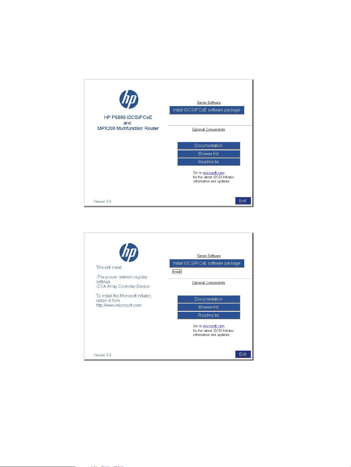
1. Install the HP P6000 iSCSI/FCoE and MPX200 Multifunction Router kit.
a. Start the installer by running Launch.exe; if you are using a CD-ROM, the installer
should start automatically.
b. Click Install iSCSI/FCoE software package (see Figure 28 (page 95) and Figure 29
(page 95)).
Figure 28 Windows Server 2003 kit
Figure 29 Windows registry and controller device installation
For Windows Server 2003, the Microsoft iSCSI initiator installation presents an option
for installing MPIO using the Microsoft generic DSM (Microsoft MPIO Multipathing Support
for iSCSI check box). For Windows Server 2008, MPIO is installed separately. See
Figure 30 (page 96).
Set up the iSCSI Initiator 95
Page 96

Figure 30 iSCSI Initiator Installation
c. Click the Microsoft iSCSI Initiator icon to open the Control Panel applet.
The iSCSI Initiator Properties window opens.
d. Click the Discovery tab (see Figure 31 (page 96)).
Figure 31 iSCSI Initiator Properties—Discovery tab
e. In the Target Portals section, click Add.
A dialog box opens to enter the iSCSI port IP Address.
f. Click OK.
The Discovery is now complete.
2. Set up the iSCSI Host and virtual disks on HP P6000 Command View:
96 iSCSI or iSCSI/FCoE configuration rules and guidelines
Page 97

Figure 32 iSCSI Initiator Properties—Discovery tab (Windows 2008)
a. From HP P6000 Command View, click the EVA storage system icon to start the iSCSI
storage presentation. In adding a host, the iSCSI or iSCSI/FCoE modules are the target
EVA storage system.
Figure 33 Add a host
b. b. Select the Hosts folder.
Set up the iSCSI Initiator 97
Page 98

c. c. To create iSCSI Initiator host, click Add host.
A dialog box opens.
• Enter a name for the initiator host in the Name box.
• Select iSCSI as the Type.
• Select the initiator iSCSI qualified name (IQN) from the iSCSI node name list. Or,
you can enter a port WWN
• Select an OS from the Operating System list.
d. Create a virtual disk and present it to the host you created in Step 2.c. Note the numbers
in the target IQN; these target WWNs will be referenced during Initiator login. See
Figure 34 (page 98) and Figure 35 (page 98).
Figure 34 Virtual disk properties
Figure 35 Host details
98 iSCSI or iSCSI/FCoE configuration rules and guidelines
Page 99

3. Set up the iSCSI disk on the iSCSI Initiator:
a. Open the iSCSI Initiator Control Panel applet.
b. Click the Targets tab and then the Refresh button to see the available targets
(Figure 36 (page 99)). The status should be Inactive.
Figure 36 iSCSI Initiator Properties—Targets tab
c. Select the target IQN, keying off the module 1 or 2 field and the WWN field, noted in
d. Configure the target IQN:
e. Depending on the operating system, open Server Manager or Computer Management.
f. Select Disk Management.
g. Select Action > Rescan Disks. Verify that the newly assigned disk is listed. If not, a reboot
h. Prepare the disk for use by formatting and partitioning.
Multipathing
Microsoft MPIO includes support for the establishment of redundant paths to send I/O from the
initiator to the target. For Windows Server 2008 and Microsoft Windows 2012, MPIO is a separate
feature that has to be installed separately. Microsoft iSCSI Software Initiator Version 2.x includes
MPIO and has to be selected for installation. Setting up redundant paths properly is important to
ensure high availability of the target disk. Ideally, the system would have the paths use separate
NIC cards and separate network infrastructure (cables, switches, iSCSI or iSCSI/FCoE modules).
HP recommends separate target ports.
Step 2.d, and click Log On.
A dialog box opens.
• Select the Automatically box to restore this connection when the system boots.
• Select the Multipathing box to enable MPIO. The target status is Connected when
logged in.
NOTE: HP recommends using the Advanced button to selectively choose the Local
Adapter, Source IP, and Target Portal. The Target Portal IP Address is the iSCSI port to
which this initiator connection path is defined.
may be required.
Set up the iSCSI Initiator 99
Page 100

Microsoft MPIO support allows the initiator to log in to multiple sessions to the same target and
aggregate the duplicate devices into a single device exposed to Windows. Each session to the
target can be established using different NICs, network infrastructure, and target ports. If one
session fails, another session can continue processing I/O without interruption to the application.
The iSCSI target must support multiple sessions to the same target. The Microsoft iSCSI MPIO DSM
supports a set of load balance policies that determine how I/O is allocated among the different
sessions. With Microsoft MPIO, the load balance policies apply to each LUN individually.
The Microsoft iSCSI DSM v2.x assumes that all targets are active/active and can handle I/O on
any path at any time. There is no mechanism within the iSCSI protocol to determine whether a
target is active/active or active/passive; therefore, the iSCSI or iSCSI/FCoE modules support only
multipath configurations with the EVA with active/active support. More information can be found
at:
http://www.microsoft.com/WindowsServer2003/technologies/storage/mpio/default.mspx
http://www.microsoft.com/WindowsServer2003/technologies/storage/mpio/faq.mspx
http://download.microsoft.com/download/3/0/4/304083f1-11e7-44d9-92b9-2f3cdbf01048/
mpio.doc
Table 20 (page 100) details the differences between Windows Server 2008 and Windows Server
2003.
Table 20 Windows server differences
Windows Server 2003Windows Server 2008 and 2012
Table 21 (page 100) shows the supported MPIO options for the iSCSI or iSCSI/FCoE controller.
Table 21 Supported MPIO options for iSCSI or iSCSI/FCoE modules
DSM for EVA*
*Preferred
Installing the MPIO feature for Windows Server 2012
NOTE: Microsoft Windows 2012 includes a separate MIOP feature that requires installation for
use. Microsoft Windows Server 2012 also includes the iSCSI Initiator. Download or installation is
not required.
Installing the MPIO feature for Windows Server 2012:
Separate installationIncluded with operating systemiSCSI Initiator
Included with iSCSI initiatorFeature has to be installedMPIO
Windows Server 2003Windows Server 2008 and 2012
SupportedSupportedHP MPIO Full Featured
SupportedSupportedMicrosoft generic DSM
100 iSCSI or iSCSI/FCoE configuration rules and guidelines
 Loading...