

Page 1

HPE ProLiant DL20 Gen9 Server
Abstract
This document is for the person who installs, administers, and troubleshoots servers and storage systems. Hewlett Packard Enterprise
Part Number: 826318-001
December 2015
Edition: 1
User Guide
assumes you are qualified in the servicing of computer equipment and trained in recognizing hazards in products with hazardous energy
levels.
Page 2

© Copyright 2015 Hewlett Packard Enterprise Development LP
The information contained herein is subject to change without notice. The only warranties for Hewlett Packard Enterprise products and services
are set forth in the express warranty statements accompanying such products and services. Nothing herein should be construed as constituting
an additional warranty. Hewlett Packard Enterprise shall not be liable for technical or editorial errors or omissions contained herein.
Links to third-party websites take you outside the Hewlett Packard Enterprise website. Hewlett Packard Enterprise has no control over and is not
responsible for information outside the Hewlett Packard Enterprise website.
®
is the registered trademark of Linus Torvalds in the U.S. and other countries.
Linux
®
Microsoft
and Windows® are trademarks of the Microsoft group of companies.
microSD is a trademark or a registered trademark of SD-3C in the United States, other countries or both.
®
Red Hat
VMware
is a registered trademark of Red Hat, Inc. in the United States and other countries.
®
is a registered trademark or trademark of VMware, Inc. in the United States and/or other jurisdictions.
Page 3

Contents
Component identification .......................................................................................................................... 6
Front panel components ........................................................................................................................................... 6
Serial label pull tab information ................................................................................................................................ 7
Front panel LEDs and buttons .................................................................................................................................. 8
Front panel LED power fault codes ............................................................................................................... 8
Rear panel components ........................................................................................................................................... 9
Rear panel LEDs .................................................................................................................................................... 10
PCIe riser board slot definitions ............................................................................................................................. 10
System board components ..................................................................................................................................... 11
DIMM slot locations ..................................................................................................................................... 12
System maintenance switch ........................................................................................................................ 13
NMI functionality .......................................................................................................................................... 13
Drive numbering ..................................................................................................................................................... 13
HPE SmartDrive LED definitions ............................................................................................................................ 15
Fan locations .......................................................................................................................................................... 16
Operations .............................................................................................................................................. 17
Remove the security bezel ..................................................................................................................................... 17
Power up the server ............................................................................................................................................... 17
Power down the server ........................................................................................................................................... 17
Extend the server from the rack ............................................................................................................................. 18
Remove the server from the rack ........................................................................................................................... 19
Remove the access panel ...................................................................................................................................... 20
Install the access panel .......................................................................................................................................... 21
Remove the PCI riser cage .................................................................................................................................... 22
Install the PCI riser cage ........................................................................................................................................ 23
Remove the air baffle ............................................................................................................................................. 24
Install the air baffle ................................................................................................................................................. 24
Setup ...................................................................................................................................................... 26
Optional services .................................................................................................................................................... 26
Optimum environment ............................................................................................................................................ 26
Space and airflow requirements .................................................................................................................. 26
Temperature requirements .......................................................................................................................... 27
Power requirements .................................................................................................................................... 27
Electrical grounding requirements ............................................................................................................... 28
Server warnings and cautions ................................................................................................................................ 28
Rack warnings ........................................................................................................................................................ 29
Identifying the contents of the server shipping carton ............................................................................................ 29
Installing hardware options ..................................................................................................................................... 30
Installing the server into the rack ............................................................................................................................ 30
Installing the rack rail hook-and-loop strap ............................................................................................................. 33
Installing the operating system ............................................................................................................................... 34
Powering on and selecting boot options in UEFI Boot Mode ................................................................................. 35
Registering the server ............................................................................................................................................ 35
Hardware options installation .................................................................................................................. 36
Introduction ............................................................................................................................................................. 36
Security bezel option .............................................................................................................................................. 36
Drive options .......................................................................................................................................................... 36
Drive installation guidelines ......................................................................................................................... 37
Installing a non-hot-plug drive ..................................................................................................................... 37
Installing a hot-plug drive............................................................................................................................. 38
Drive cable options ................................................................................................................................................. 39
2 LFF Smart Array Controller Mini-SAS cable option .................................................................................. 40
Contents 3
Page 4

4 SFF Smart Array Controller Mini-SAS cable option.................................................................................. 43
Controller options ................................................................................................................................................... 46
Installing the storage controller and FBWC module options........................................................................ 46
Installing an HPE Smart Storage Battery .................................................................................................... 48
M.2 SSD SATA cable and optical drive extension power cable option .................................................................. 50
Installing one M.2 SSD and one optical drive .............................................................................................. 50
Installing two M.2 SSDs............................................................................................................................... 57
Memory options ...................................................................................................................................................... 63
Memory subsystem architecture.................................................................................................................. 64
Single-, dual-, and quad-rank DIMMs .......................................................................................................... 64
DIMM identification ...................................................................................................................................... 64
Memory configurations ................................................................................................................................ 65
General DIMM slot population guidelines .................................................................................................... 66
Installing a DIMM ......................................................................................................................................... 66
FlexibleLOM riser cage assembly .......................................................................................................................... 67
GPU riser cage assembly ....................................................................................................................................... 68
Two-slot PCI riser cage assembly .......................................................................................................................... 70
Redundant power supply option ............................................................................................................................. 71
HPE Trusted Platform Module option ..................................................................................................................... 77
Installing the Trusted Platform Module board .............................................................................................. 78
Retaining the recovery key/password.......................................................................................................... 79
Enabling the Trusted Platform Module ........................................................................................................ 80
Cabling .................................................................................................................................................... 81
Cabling overview .................................................................................................................................................... 81
Storage cabling ...................................................................................................................................................... 81
2-bay LFF non-hot-plug drive cabling .......................................................................................................... 81
2-bay LFF hot-plug drive cabling ................................................................................................................. 82
4-bay SFF hot-plug drive cabling................................................................................................................. 82
M.2 SSD cabling .......................................................................................................................................... 82
FBWC module cabling ............................................................................................................................................ 85
Smart Storage Battery cabling ............................................................................................................................... 86
H240 Host Bus Adapter cabling ............................................................................................................................. 87
Optical drive cabling ............................................................................................................................................... 88
Fan cabling ............................................................................................................................................................. 89
Power supply cabling ............................................................................................................................................. 90
HPE 290 W non-hot-plug power supply cabling .......................................................................................... 90
Redundant Power Supply backplane cabling .............................................................................................. 90
Front I/O cabling ..................................................................................................................................................... 91
P440 Smart Array Controller cabling ...................................................................................................................... 91
Software and configuration utilities ......................................................................................................... 93
Server mode ........................................................................................................................................................... 93
Product QuickSpecs ............................................................................................................................................... 93
HPE iLO ................................................................................................................................................................. 93
Active Health System .................................................................................................................................. 94
RESTful API support for iLO........................................................................................................................ 95
Integrated Management Log ....................................................................................................................... 95
HPE Insight Remote Support ...................................................................................................................... 95
Intelligent Provisioning ........................................................................................................................................... 96
HPE Insight Diagnostics .............................................................................................................................. 97
Erase Utility ................................................................................................................................................. 97
Scripting Toolkit for Windows and Linux ................................................................................................................ 98
Service Pack for ProLiant ....................................................................................................................................... 98
HP Smart Update Manager ......................................................................................................................... 98
HPE UEFI System Utilities ..................................................................................................................................... 98
Using UEFI System Utilities ......................................................................................................................... 99
Flexible boot control .................................................................................................................................... 99
Restoring and customizing configuration settings ..................................................................................... 100
Secure Boot configuration ......................................................................................................................... 100
Embedded UEFI shell................................................................................................................................ 100
Embedded Diagnostics option ................................................................................................................... 100
Contents 4
Page 5

RESTful API support for UEFI ................................................................................................................... 101
Re-entering the server serial number and product ID ............................................................................... 101
Utilities and features ............................................................................................................................................. 101
HPE Smart Storage Administrator ............................................................................................................. 101
Automatic Server Recovery ....................................................................................................................... 102
USB support .............................................................................................................................................. 102
Redundant ROM support........................................................................................................................... 102
Keeping the system current .................................................................................................................................. 103
Access to Hewlett Packard Enterprise Support Materials ......................................................................... 103
Updating firmware or System ROM ........................................................................................................... 103
Drivers ....................................................................................................................................................... 105
Software and firmware............................................................................................................................... 105
Operating System Version Support ........................................................................................................... 105
Version control........................................................................................................................................... 105
Operating systems and virtualization software support for ProLiant servers ............................................. 106
HPE Technology Service Portfolio ............................................................................................................ 106
Change control and proactive notification ................................................................................................. 106
Troubleshooting .................................................................................................................................... 107
Troubleshooting resources ................................................................................................................................... 107
System battery replacement ................................................................................................................. 108
Regulatory information .......................................................................................................................... 110
Safety and regulatory compliance ........................................................................................................................ 110
Belarus Kazakhstan Russia marking .................................................................................................................... 110
Turkey RoHS material content declaration ........................................................................................................... 111
Ukraine RoHS material content declaration ......................................................................................................... 111
Warranty information ............................................................................................................................................ 111
Specifications ........................................................................................................................................ 112
Environmental specifications ................................................................................................................................ 112
Mechanical specifications ..................................................................................................................................... 112
Power supply specifications ................................................................................................................................. 112
Hot-plug power supply calculations ...................................................................................................................... 113
Support and other resources ................................................................................................................ 114
Accessing Hewlett Packard Enterprise Support ................................................................................................... 114
Information to collect ................................................................................................................................. 114
Accessing updates ............................................................................................................................................... 114
Websites ............................................................................................................................................................... 114
Customer Self Repair ........................................................................................................................................... 115
Remote support .................................................................................................................................................... 122
Acronyms and abbreviations................................................................................................................. 123
Documentation feedback ...................................................................................................................... 127
Index ..................................................................................................................................................... 128
Contents 5
Page 6
Component identification
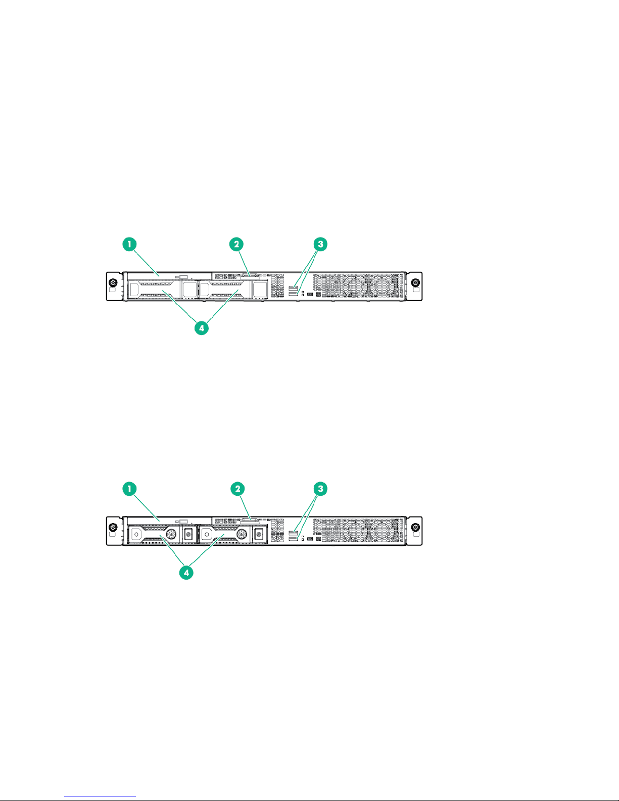
Front panel components
• 2-bay LFF non-hot-plug drive model
• 2-bay LFF hot-plug drive model
Component identification 6
Page 7
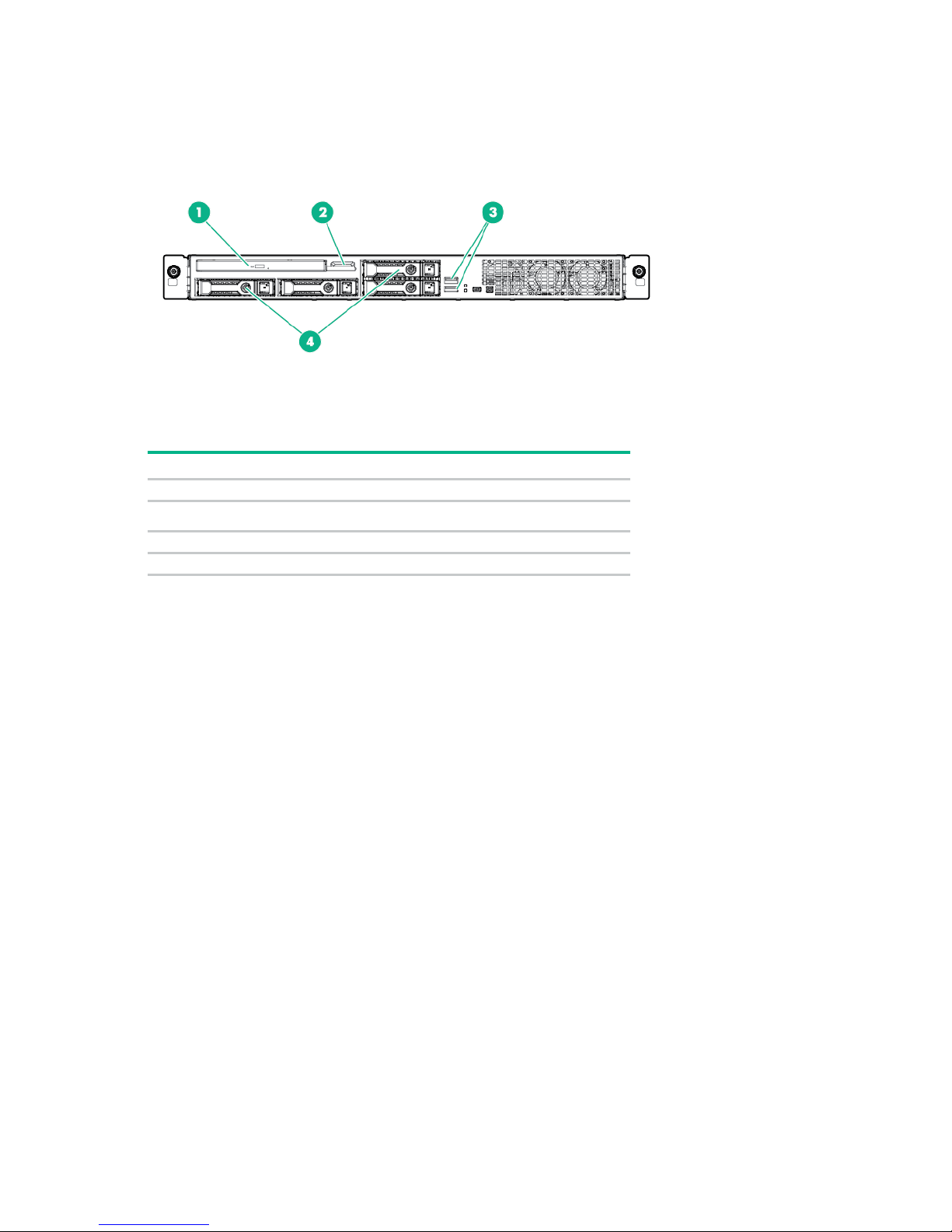
• 4-bay SFF hot-plug drive model
Item
Description
1
Optical drive (optional)
Serial label pull tab ("Serial label pull tab information" on page 7)
3
USB 2.0 connectors
4
Drive bays
2
Serial label pull tab information
The horizontally-oriented node serial number and iLO label pull tab is located on the rear node panel. The
following server labels are attached to this pull tab:
• Top—Server serial number label
• Bottom—Default iLO account information label and customer asset tag label
Component identification 7
Page 8
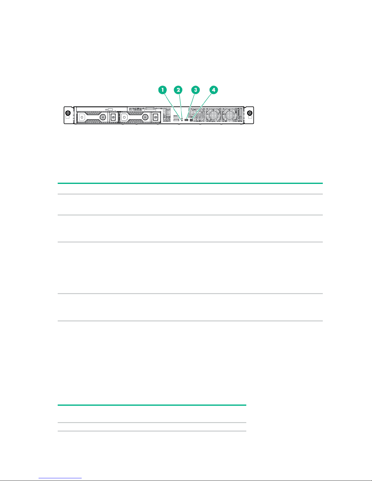
Front panel LEDs and buttons
Item
Description
Status
NIC status LED*
Solid green = Link to network
Health LED*
Solid green = Normal
UID button/LED*
Solid blue = Activated
•
•
•
Power On/Standby
Solid green = System on
behavior
System board
1 flash
1
Flashing green (1 flash per second) = Network active
Off = No network activity
2
Flashing green (1 flash per second) = iLO is rebooting
Flashing amber = System degraded**
Flashing red (1 flash per second) = System critical**
3
Flashing blue:
1 flash per second = Remote management or firmware upgrade in
progress
4 flashes per second = iLO manual reboot sequence initiated
8 flashes per second = iLO manual reboot sequence in progress
Off = Deactivated
4
* When all four LEDs described in this table flash simultaneously, a power fault has occurred. For more information,
see "Front panel LED power fault codes (on page 8)."
** If the health LED indicates a degraded or critical state, review the system IML or use iLO to review the system
health status.
† Facility power is not present, power cord is not attached, no power supplies are installed, power supply failure has
occurred, or the front I/O cable is disconnected.
button and system
power LED*
Flashing green (1 flash per second) = Performing power on sequence
Solid amber = System in standby
Off = No power present†
Front panel LED power fault codes
The following table provides a list of power fault codes, and the subsystems that are affected. Not all
power faults are used by all servers.
Subsystem
Front panel LED
Component identification 8
Page 9
behavior
Processor
2 flashes
Memory
3 flashes
Riser board PCIe slots
4 flashes
FlexibleLOM
5 flashes
controller/Smart SAS HBA controller
6 flashes
System board PCIe slots
7 flashes
Power backplane or storage backplane
8 flashes
Power supply
9 flashes
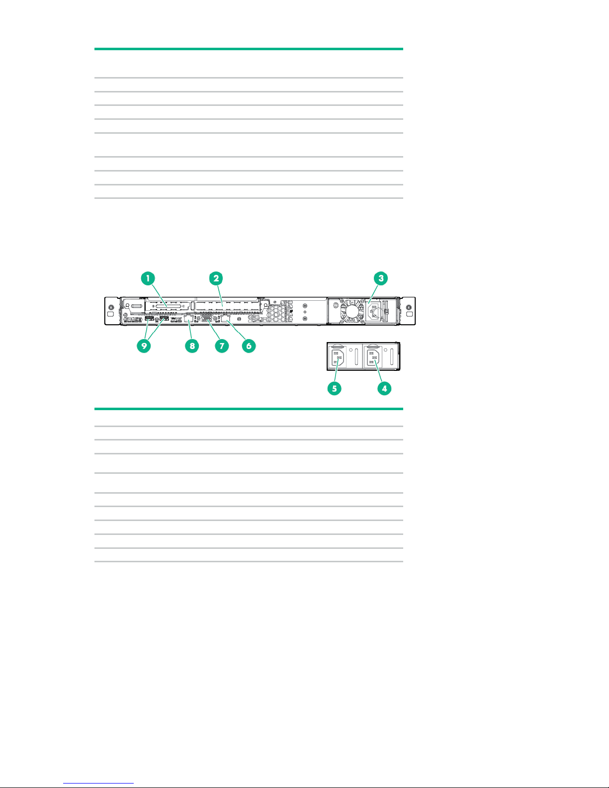
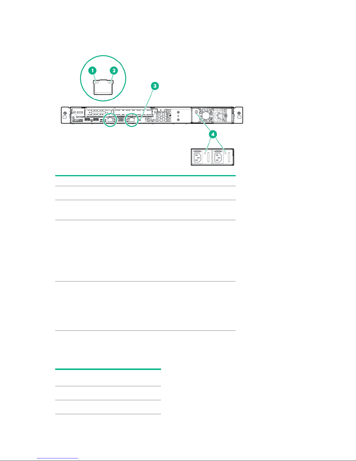
Item
Description
1
Slot 1 PCIe/FlexibleLOM
2
Slot 2 PCIe
Non-hot-plug power supply
Hot-plug power supply 2
5
Hot-plug power supply 1
6
NIC connector 2
7
Video connector
8
NIC connector 1/iLO management connector
9
USB 3.0 connectors (2)
Subsystem
Removable HPE Flexible Smart Array
For more information, see "Front panel LEDs and buttons (on page 8)."
Rear panel components
Front panel LED
3
4
Component identification 9
Page 10
Rear panel LEDs
Item
Description
Status
NIC link LED
Green = Network link
NIC activity LED
Solid green = Link to network
UID LED
Solid blue = Activated
•
•
•
Power supply LED
Solid green = Normal
•
•
•
•
number
factor
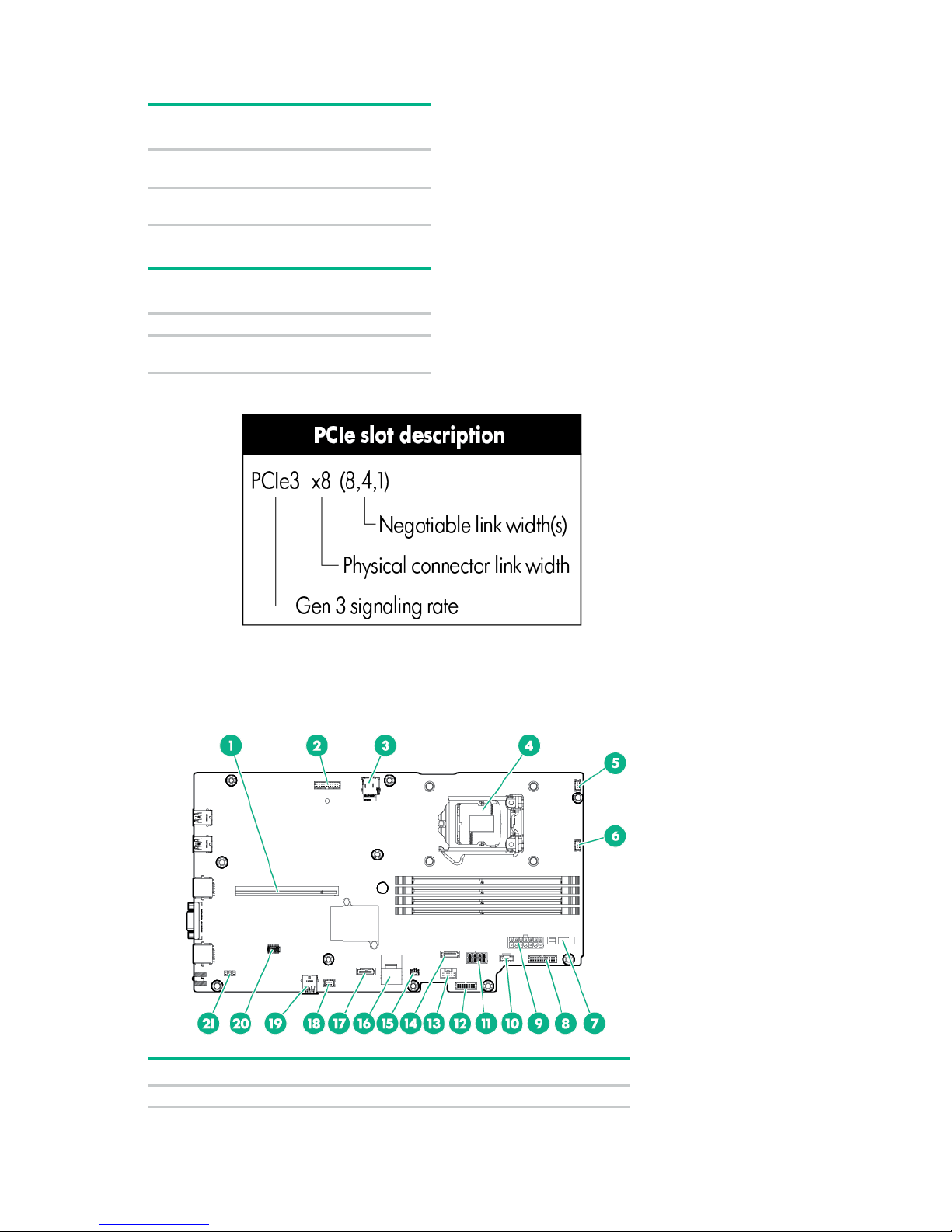
description
slot
FlexibleLOM
PCIe x8
PCIe 3
PCIe3 x8
1
Off = No network link
2
Flashing green = Network active
Off = No network activity
3
Flashing blue:
1 flash per second = Remote management
or firmware upgrade in progress
4 flashes per second = iLO manual reboot
sequence initiated
8 flashes per second = iLO manual reboot
sequence in progress
Off = Deactivated
4
Off = One or more of the following conditions
exists:
Power is unavailable
Power supply failed
Power supply is in standby mode
Power supply error
PCIe riser board slot definitions
• FlexibleLOM riser board
Slot
FlexibleLOM
Slot 2
Form
Slot
(8,4,2,1)
Component identification 10
Page 11
• Two-slot riser board
number
factor
description
Low-profile
PCIe3 x8
Full-height,
PCIe3 x8
number
factor
description
—
—
—
Full-height,
PCIe3 x16
Item
Description
1
PCIe riser connector*
Slot
Form
Slot
1
2
• GPU riser board
Slot
2
half-length
Form
half-length
(8,4,2,1)
(8,4,2,1)
Slot
(16,8,4,1)
System board components
Component identification 11
Page 12
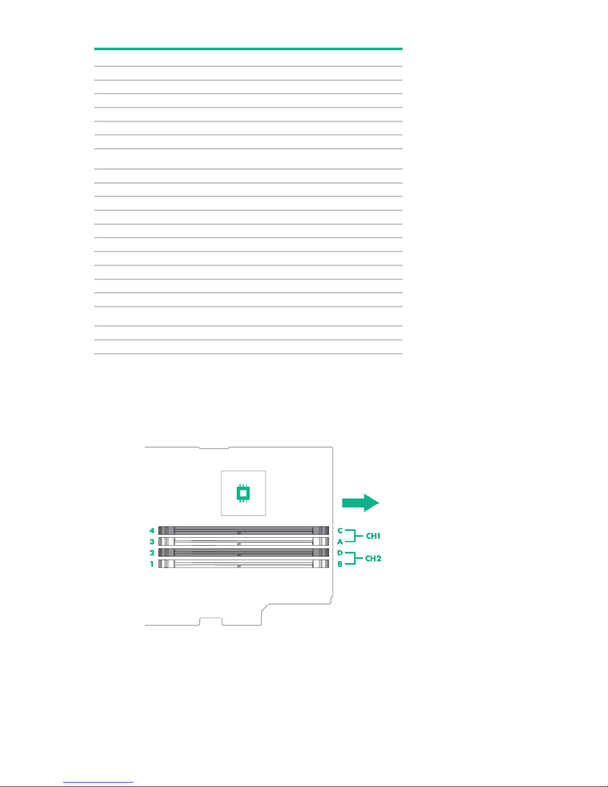
Item
Description
2
Trusted module connector
3
microSD slot
4
Processor
5
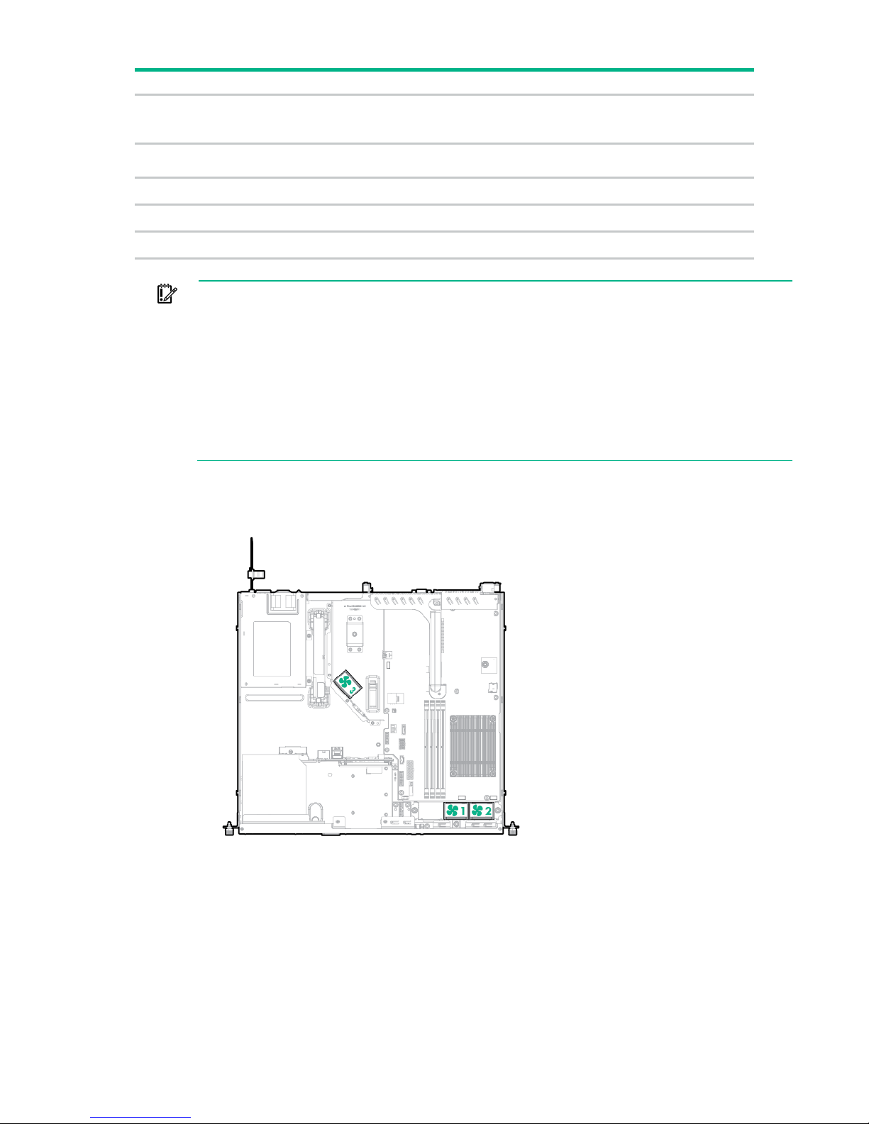
Fan connector 2
6
Fan connector 1
7
System battery
8
Front I/O connector
9
14-pin power connector
10
4-pin power connector
11
8-pin power connector
12
Power supply sideband signal connector
13
Smart Storage Battery connector
14
SATA connector for M.2 SSD/optical drive
15
Storage backup power connector
16
Mini-SAS connector
17
SATA connector for M.2 SSD
18
Fan connector 3
Internal USB 3.0 connector
20
System maintenance switch
21
NMI header
19
For more information on the riser board slots supported by the onboard PCI riser connectors, see "PCIe
riser board slot definitions (on page 10)."
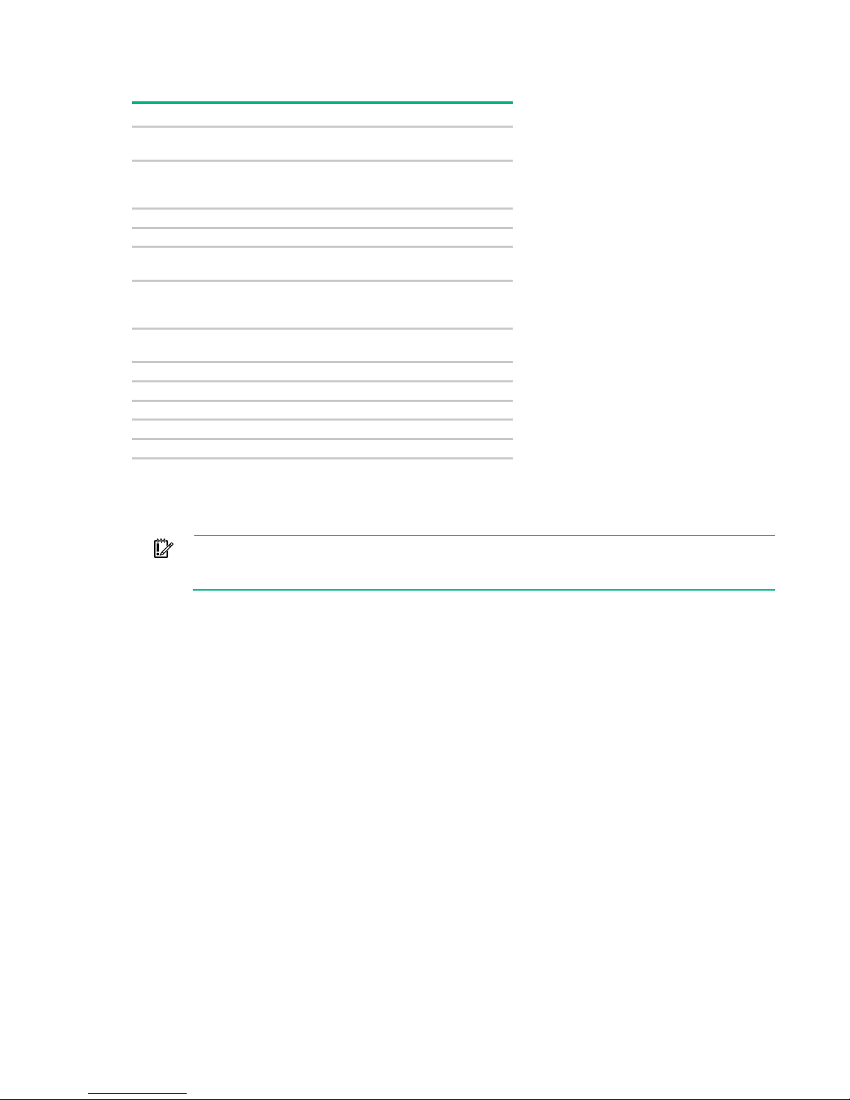
DIMM slot locations
The arrow points to the front of the server.
Component identification 12
Page 13
Position
Default
Function
Off
Off = iLO 4 security is enabled.
Off
Off = System configuration can be
S3
Off
Reserved
S4
Off
Reserved
Off
Off = Power-on password is enabled.
Off
Off = No function
Off
Off = Set default boot mode to UEFI.
S8
—
Reserved
S9
—
Reserved
S10
—
Reserved
S11
—
Reserved
S12
—
Reserved
Before using the S7 switch to change to Legacy BIOS Boot Mode, be sure the
HPE Dynamic Smart Array B140i Controller is disabled. Do not use the B140i controller when
System maintenance switch
S1
On = iLO 4 security is disabled.
S2
changed.
On = System configuration is locked.
S5
On = Power-on password is disabled.
S6
On = ROM reads system
configuration as invalid.
S7
On = Set default boot mode to legacy.
To access the redundant ROM, set S1, S5, and S6 to on.
When system maintenance switch S6 is set to the On position, the system is prepared to erase all system
configuration settings from both CMOS and NVRAM.
IMPORTANT:
the server is in Legacy BIOS Boot Mode.
NMI functionality
An NMI crash dump creates a crash dump log before resetting a system which is not responding.
Crash dump log analysis is an essential part of diagnosing reliability problems, such as failures of
operating systems, device drivers, and applications. Many crashes freeze a system, and the only
available action for administrators is to restart the system. Resetting the system erases any information
which could support problem analysis, but the NMI feature preserves that information by performing a
memory dump before a system reset.
To force the system to invoke the NMI handler and generate a crash dump log, do one of the following:
• Use the iLO Virtual NMI feature.
• Short the NMI header ("System board components" on page 11).
For more information, see the Hewlett Packard Enterprise website (http://www.hpe.com/support/NMI).
Drive numbering
The following images show the drive numbering for each of the supported drive configurations. For drive
box numbering information, see "Front panel components (on page 6)."
Component identification 13
Page 14
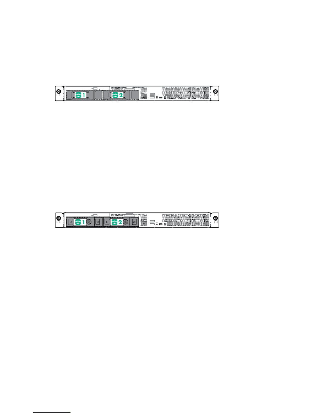
• 2-bay LFF non-hot-plug drive model
• 2-bay LFF hot-plug drive model
Component identification 14
Page 15
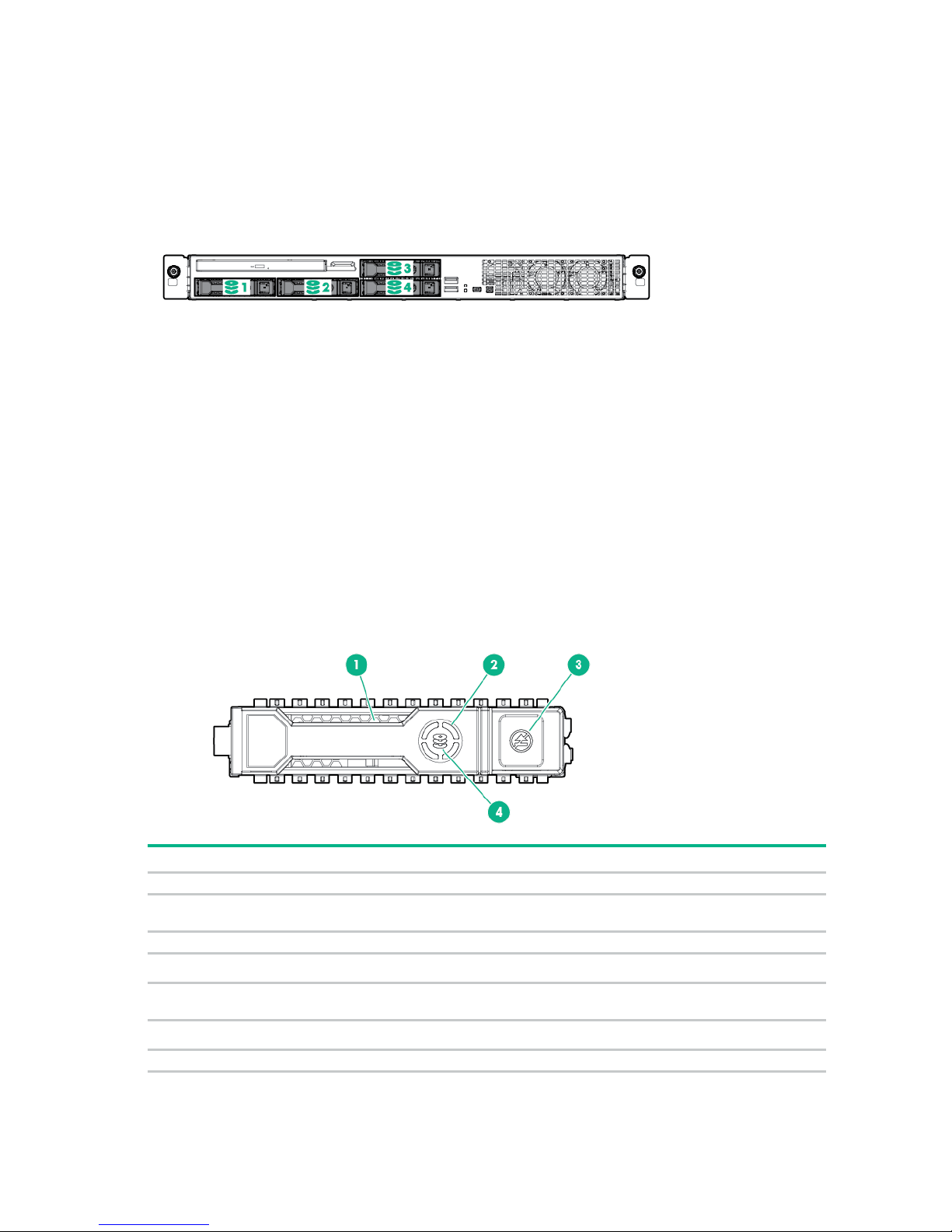
• 4-bay SFF hot-plug drive model
Item
LED
Status
Definition
1
Locate
Solid blue
The drive is being identified by a host application.
Flashing blue
The drive carrier firmware is being updated or requires an
2
Activity ring
Rotating green
Drive activity
Off
No drive activity
Do not remove
Solid white
Do not remove the drive. Removing the drive causes one or
Off
Removing the drive does not cause a logical drive to fail.
4
Drive status
Solid green
The drive is a member of one or more logical drives.
HPE SmartDrive LED definitions
HPE SmartDrives are the latest Hewlett Packard Enterprise drive technology, and they are supported
beginning with ProLiant Gen8 servers and server blades. The SmartDrive is not supported on earlier
generation servers and server blades. Identify a SmartDrive by its carrier, shown in the following
illustration.
When a drive is configured as a part of an array and connected to a powered-up controller, the drive LEDs
indicate the condition of the drive.
3
update.
more of the logical drives to fail.
Component identification 15
Page 16
Item
LED
Status
Definition
Flashing green
The drive is rebuilding or performing a RAID migration, strip size
Flashing
The drive is a member of one or more logical drives and predicts
Flashing amber
The drive is not configured and predicts the drive will fail.
Solid amber
The drive has failed.
Off
The drive is not configured by a RAID controller.
The Dynamic Smart Array B140i Controller is only available in UEFI Boot Mode.
r
The blue Locate LED is behind the release lever and is visible when illuminated.
IMPORTANT:
It cannot be enabled in Legacy BIOS Boot Mode. If the B140i controller is disabled, drives
connected to the system board Mini-SAS connectors operate in AHCI or Legacy mode. Unde
this condition:
• The drives cannot be a part of a hardware RAID or a logical drive.
• The Locate, Drive status, and Do not remove LEDs of the affected drives are disabled.
Use BIOS/Platform Configuration (RBSU) in the UEFI System Utilities ("HPE UEFI System
Utilities" on page 98) to enable or disable the B140i controller (System Configuration →
BIOS/Platform Configuration (RBSU) → System Options → SATA Controller Options →
Embedded SATA Configuration).
Fan locations
amber/green
migration, capacity expansion, or logical drive extension, or is
erasing.
the drive will fail.
Component identification 16
Page 17
Operations
Remove the security bezel
To access the front panel components, unlock and then remove the security bezel.
Power up the server
To power up the server, press the Power On/Standby button.
Power down the server
Before powering down the server for any upgrade or maintenance procedures, perform a backup of
critical server data and programs.
IMPORTANT: When the server is in standby mode, auxiliary power is still being provided to
the system.
To power down the server, use one of the following methods:
• Press and release the Power On/Standby button.
This method initiates a controlled shutdown of applications and the OS before the server enters
standby mode.
• Press and hold the Power On/Standby button for more than 4 seconds to force the server to enter
standby mode.
This method forces the server to enter standby mode without properly exiting applications and the
OS. If an application stops responding, you can use this method to force a shutdown.
• Use a virtual power button selection through iLO 4.
This method initiates a controlled remote shutdown of applications and the OS before the server
enters standby mode.
Operations 17
Page 18
To reduce the risk of personal injury or equipment damage, be sure that the rack
Before proceeding, verify the server is in standby mode by observing that the system power LED is
amber.
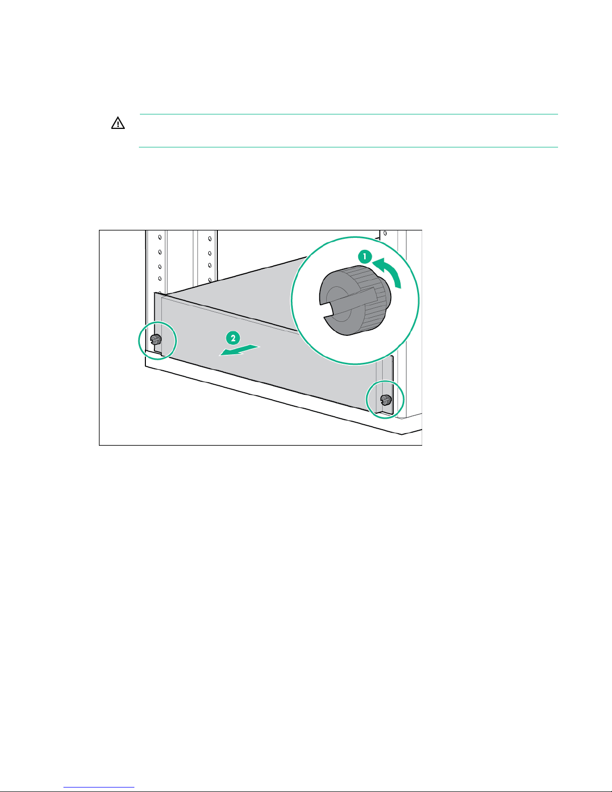
Extend the server from the rack
WARNING:
is adequately stabilized before extending a component from the rack.
1. Power down the server (on page 17).
2. Disconnect all peripheral cables from the server.
3. Disconnect each power cord from the server.
4. In a server that uses thumbscrew rack ears, loosen the captive thumbscrews that secure the server
faceplate to the front of the rack, and then slide the server out of the rack.
5. In a server that uses quick-release latch rack ears:
a. Open the latches on both sides of the server.
b. If necessary, use a T-25 Torx screwdriver to loosen the shipping screws.
Operations 18
Page 19
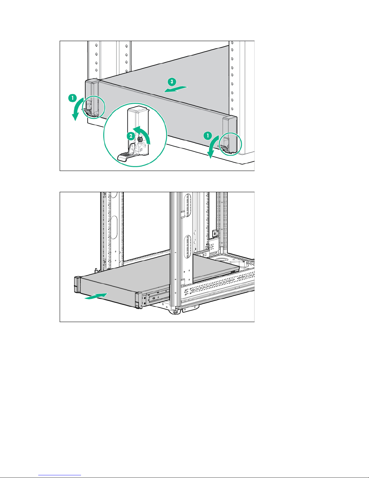
c.
Slide the server out of the rack.
6. After performing the installation or maintenance procedure, slide the server back into the rack, and
then press the server firmly into the rack to secure it in place.
7. Do one of the following:
o In a server that uses thumbscrew rack ears, tighten the captive thumbscrews.
o In a server that uses quick-release latch rack ears, if necessary, tighten the shipping screws.
8. Connect each power cord to the server.
9. Connect all peripheral cables to the server.
10. Power up the server (on page 17).
Remove the server from the rack
Operations 19
Page 20
This server is very heavy. To reduce the risk of personal injury or damage to the
minimum of two people are required for all rack server installations. A third person may be
or removing the server from the rack; it is unstable
s in improper airflow and improper cooling
WARNING:
equipment:
• Observe local occupational health and safety requirements and guidelines for manual
material handling.
• Get help to lift and stabilize the product during installation or removal, especially when the
product is not fastened to the rails. Hewlett Packard Enterprise recommends that a
required to help align the server if the server is installed higher than chest level.
• Use caution when installing the server in
when not fastened to the rails.
To remove the server from a Hewlett Packard Enterprise, Compaq-branded, Telco, or a third-party rack:
1. Power down the server (on page 17).
2. Extend the server on the rack rails until the server rail-release latches engage.
3. Disconnect all peripheral cables from the server.
4. Disconnect each power cord from the server.
5. Remove the server from the rack.
For instructions on how to extend or remove the server from the rack, see the documentation that
ships with the rack rail system.
6. Place the server on a sturdy, level surface.
Remove the access panel
WARNING: To reduce the risk of personal injury from hot surfaces, allow the drives and the
internal system components to cool before touching them.
CAUTION: To prevent damage to electrical components, take the appropriate anti-static
precautions before beginning any installation, removal, or replacement procedure. Improper
To remove the component:
1. If installed, remove the security bezel (on page 17).
2. Power down the server (on page 17).
3. If you are performing a non-hot-plug procedure, remove all power:
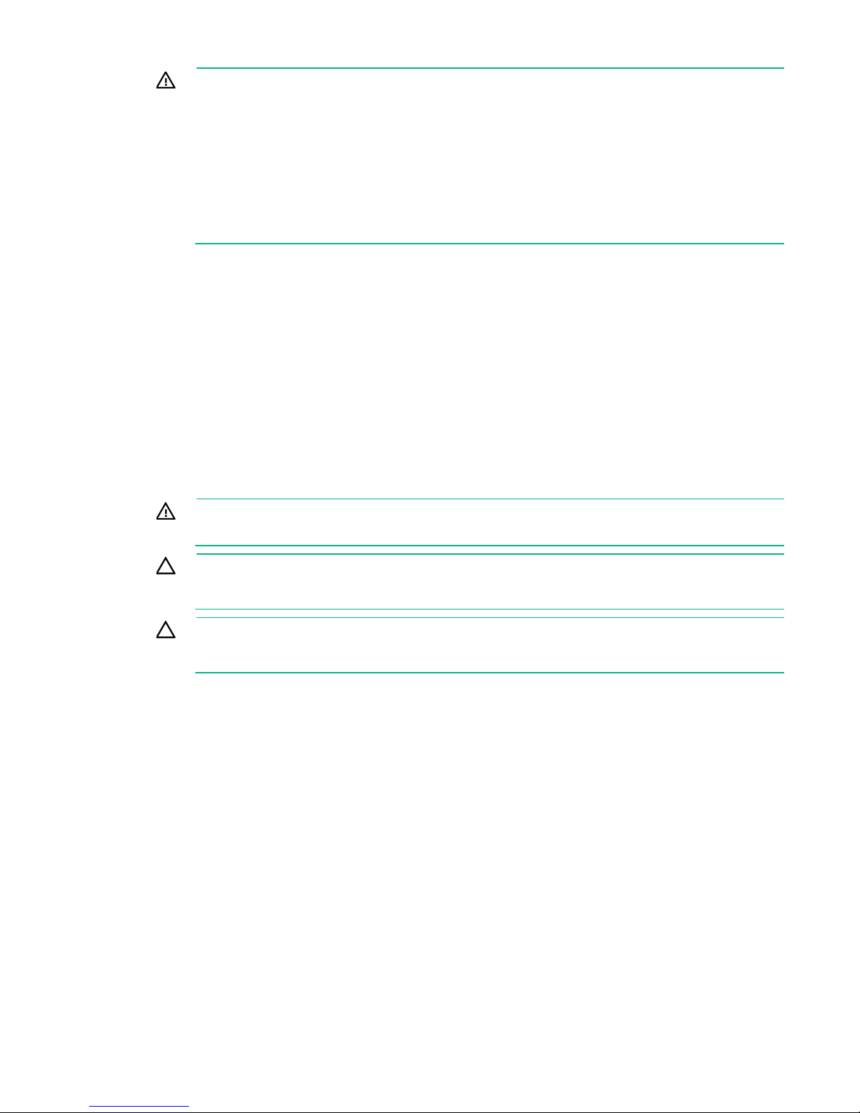
4. Do one of the following:
5. If the locking latch is locked, use a T-15 Torx screwdriver to unlock the latch.
6. Open the locking latch.
grounding can cause electrostatic discharge.
CAUTION: Do not operate the server for long periods with the access panel open or
removed. Operating the server in this manner result
that can lead to thermal damage.
a. Disconnect each power cord from the power source.
b. Disconnect each power cord from the server.
o Extend the server from the rack (on page 18).
o Remove the server from the rack (on page 19).
The access panel slides back, releasing it from the chassis.
Operations 20
Page 21
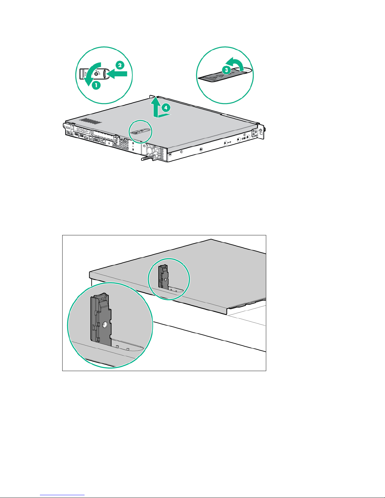
7.
Lift and remove the access panel.
Turn the access panel over to locate the server hood label. This label provides convenient access to
component identification, LED status indicators, and system maintenance switch settings information.
Install the access panel
1. Ensure that the access panel latch is in the open position.
2. Align the hole in the access panel latch with the guide pin on the chassis.
3. Close the access panel latch. The access panel slides to a closed position.
Operations 21
Page 22

4.
To prevent damage to the server or expansion boards, power down the server, and
Use a T-15 Torx screwdriver to tighten the access panel latch screw.
Remove the PCI riser cage
WARNING: To reduce the risk of personal injury from hot surfaces, allow the drives and the
internal system components to cool before touching them.
CAUTION:
disconnect all power cords before removing or installing the PCI riser cage.
1. If installed, remove the security bezel (on page 17).
2. Power down the server (on page 17).
3. Remove all power:
a. Disconnect each power cord from the power source.
b. Disconnect each power cord from the server.
4. Do one of the following:
o Extend the server from the rack (on page 18).
o Remove the server from the rack (on page 19).
5. Remove the access panel (on page 20).
6. Disconnect all cables connected to existing expansion boards.
Operations 22
Page 23
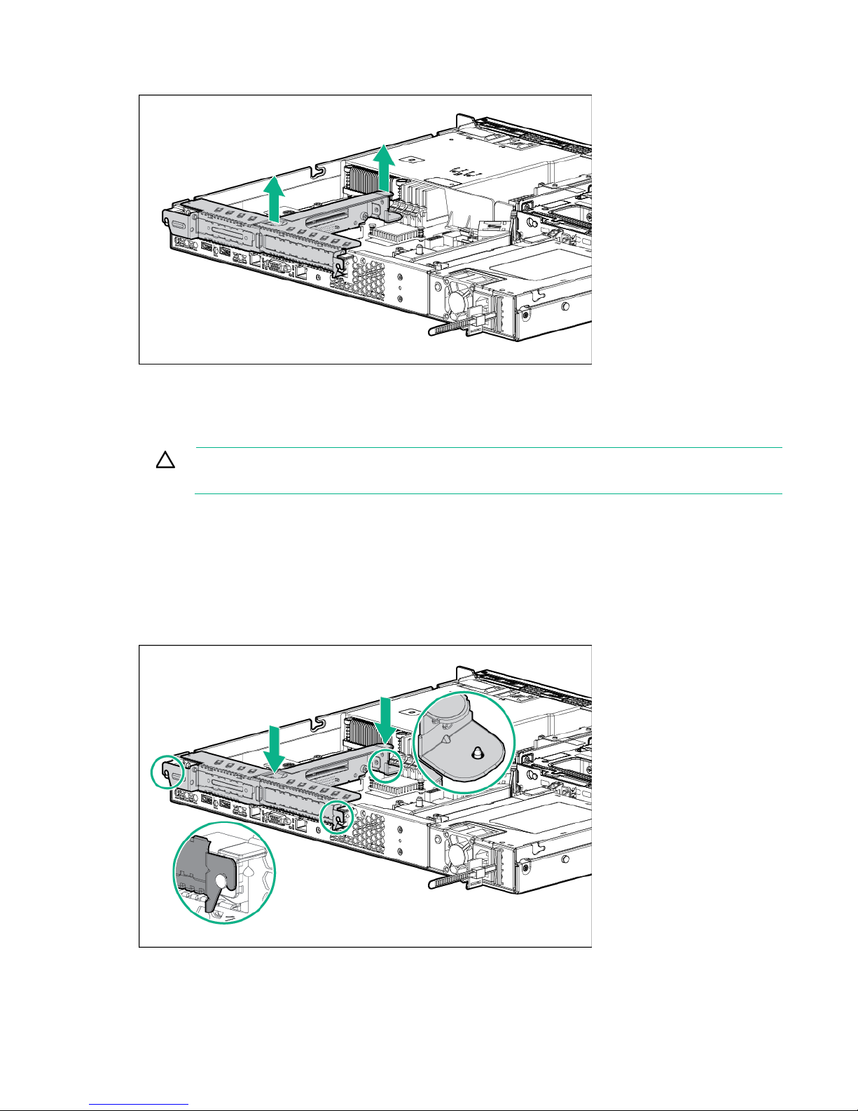
To prevent damage to the server or expansion boards, power down the server, and
7.
Remove the existing PCI riser cage.
Retain the cage for future use.
Install the PCI riser cage
CAUTION:
disconnect all power cords before removing or installing the PCI riser cage.
To install the component:
1. If cabled expansion boards are installed on the PCI riser cage, connect all necessary internal cabling
to the expansion boards.
For more information on these cabling requirements, see the documentation that ships with the
option.
2. Align the riser board with the corresponding connectors on the system board, and then press down
the PCI riser cage.
3. Install the access panel (on page 21).
4. Do one of the following:
Operations 23
Page 24
o
Slide the server into the rack.
o Install the server into the rack ("Installing the server into the rack" on page 30).
5. Power up the server (on page 17).
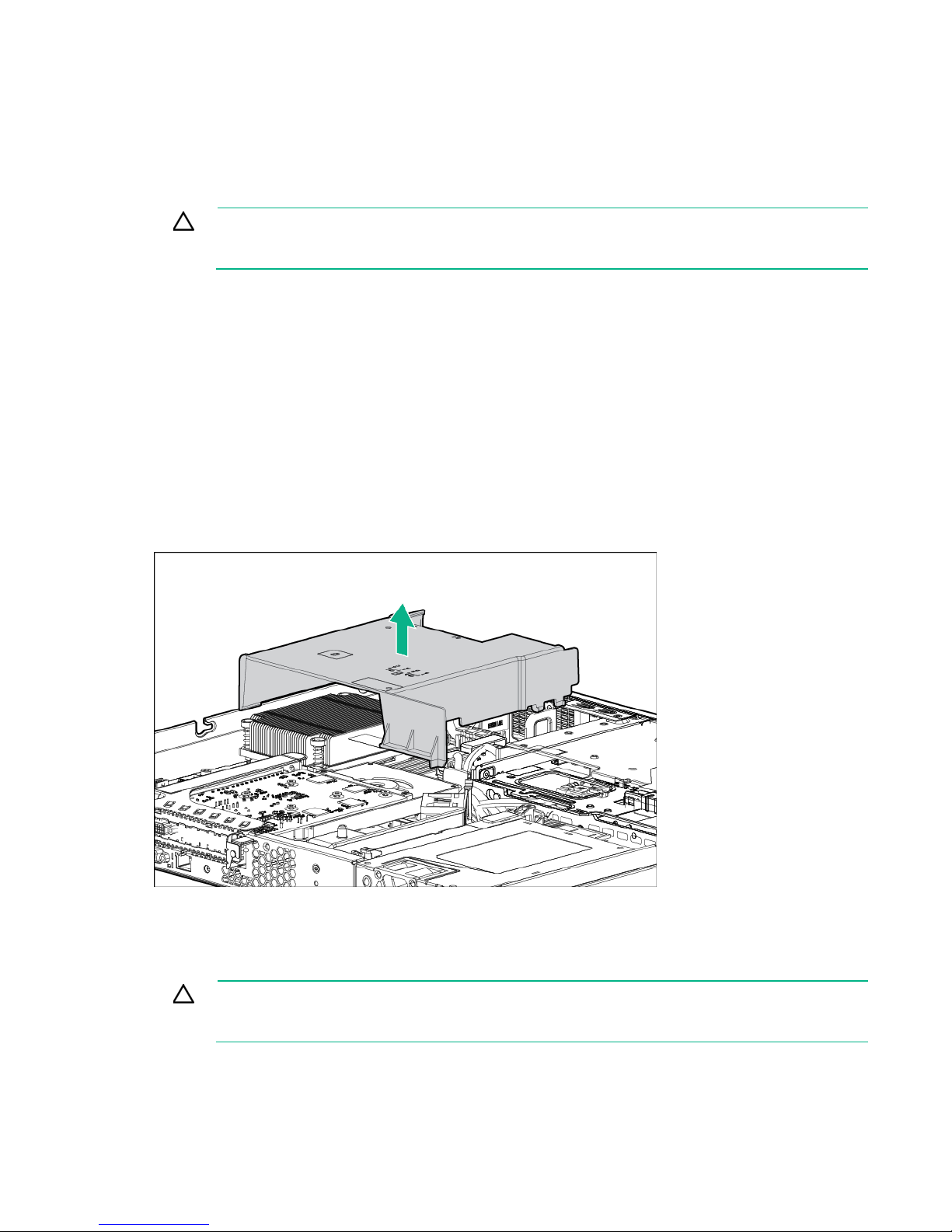
Remove the air baffle
CAUTION: For proper cooling, do not operate the server without the access panel, baffles,
expansion slot covers, or blanks installed. If the server supports hot-plug components,
To remove the component:
1. If installed, remove the security bezel (on page 17).
2. Power down the server (on page 17).
3. Remove all power:
4. Do one of the following:
5. Remove the access panel (on page 20).
6. Remove the air baffle.
minimize the amount of time the access panel is open.
a. Disconnect each power cord from the power source.
b. Disconnect each power cord from the server.
o Extend the server from the rack (on page 18).
o Remove the server from the rack (on page 19).
To replace the component, reverse the removal procedure.
Install the air baffle
CAUTION: For proper cooling, do not operate the server without the access panel, baffles,
expansion slot covers, or blanks installed. If the server supports hot-plug components,
minimize the amount of time the access panel is open.
Operations 24
Page 25
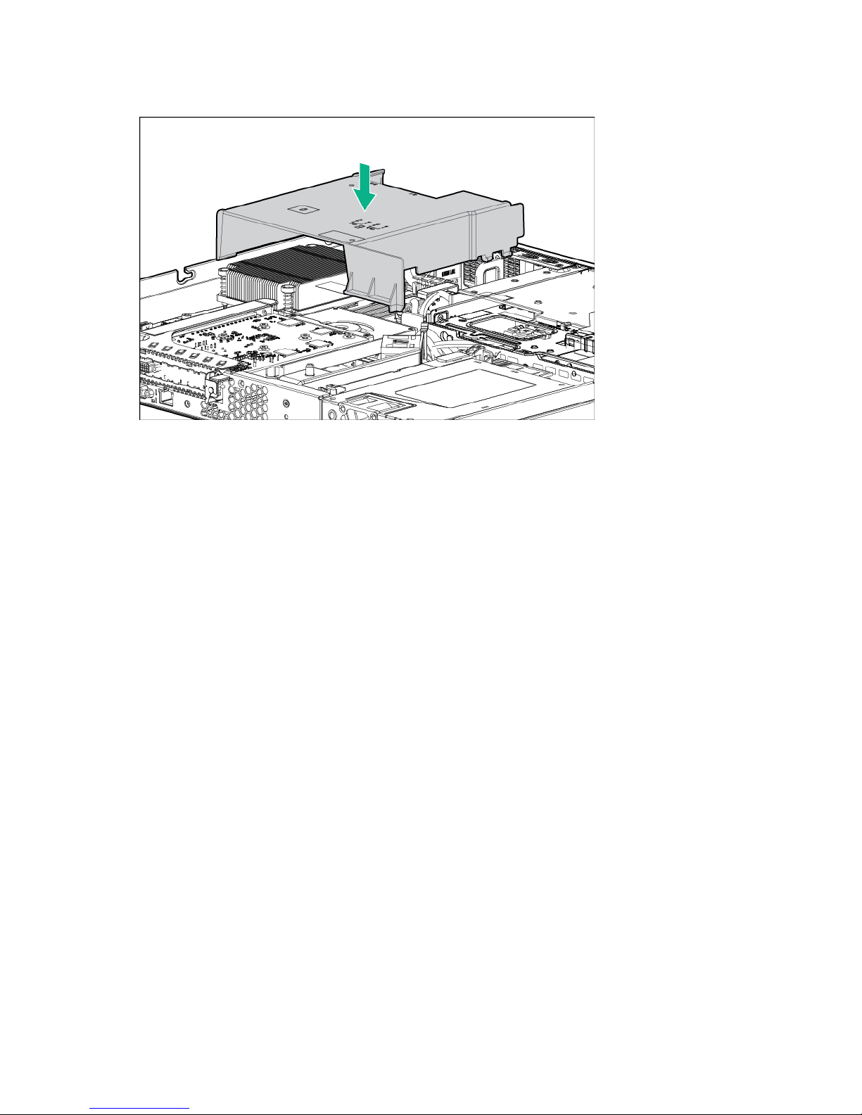
To install the component:
1. Install the air baffle.
2. Install the access panel (on page 21).
3. Do one of the following:
o Slide the server into the rack.
o Install the server into the rack ("Installing the server into the rack" on page 30).
4. Power up the server (on page 17).
Operations 25
Page 26

Setup
Optional services
Delivered by experienced, certified engineers, HP Care Pack services help you keep your servers up and
running with support packages tailored specifically for HPE ProLiant systems. HP Care Packs let you
integrate both hardware and software support into a single package. A number of service level options are
available to meet your needs.
HP Care Pack Services offer upgraded service levels to expand your standard product warranty with
easy-to-buy, easy-to-use support packages that help you make the most of your server investments.
Some of the HP Care Pack services are:
• Hardware support
o 6-Hour Call-to-Repair
o 4-Hour 24x7 Same Day
o 4-Hour Same Business Day
• Software support
o Microsoft®
o Linux
o HPE ProLiant Essentials (HPE SIM and RDP)
o VMware
• Integrated hardware and software support
o Critical Service
o Proactive 24
o Support Plus
o Support Plus 24
• Startup and implementation services for both hardware and software
For more information on HP Care Pack services, see the Hewlett Packard Enterprise website
(http://www.hpe.com/services/carepack).
Optimum environment
When installing the server in a rack, select a location that meets the environmental standards described in
Space and airflow requirements
this section.
To allow for servicing and adequate airflow, observe the following space and airflow requirements when
deciding where to install a rack:
• Leave a minimum clearance of 63.5 cm (25 in) in front of the rack.
• Leave a minimum clearance of 76.2 cm (30 in) behind the rack.
• Leave a minimum clearance of 121.9 cm (48 in) from the back of the rack to the back of another rack
or row of racks.
Setup 26
Page 27
If the 42U rack includes closing front and rear doors, you must allow
The clearance between the installed rack component and the side panels of the rack
Hewlett Packard Enterprise servers draw in cool air through the front door and expel warm air through the
rear door. Therefore, the front and rear rack doors must be adequately ventilated to allow ambient room
air to enter the cabinet, and the rear door must be adequately ventilated to allow the warm air to escape
from the cabinet.
CAUTION: To prevent improper cooling and damage to the equipment, do not block the
ventilation openings.
When vertical space in the rack is not filled by a server or rack component, the gaps between the
components cause changes in airflow through the rack and across the servers. Cover all gaps with
blanking panels to maintain proper airflow.
CAUTION: Always use blanking panels to fill empty vertical spaces in the rack. This
arrangement ensures proper airflow. Using a rack without blanking panels results in improper
cooling that can lead to thermal damage.
The 9000 and 10000 Series Racks provide proper server cooling from flow-through perforations in the
front and rear doors that provide 64 percent open area for ventilation.
CAUTION: When using a Compaq branded 7000 series rack, install the high airflow rack
door insert (PN 327281-B21 for 42U rack, PN 157847-B21 for 22U rack) to provide proper
front-to-back airflow and cooling.
CAUTION: If a third-party rack is used, observe the following additional requirements to
ensure adequate airflow and to prevent damage to the equipment:
• Front and rear doors—
5,350 sq cm (830 sq in) of holes evenly distributed from top to bottom to permit adequate
airflow (equivalent to the required 64 percent open area for ventilation).
• Side—
must be a minimum of 7 cm (2.75 in).
Temperature requirements
To ensure continued safe and reliable equipment operation, install or position the system in a
well-ventilated, climate-controlled environment.
The maximum recommended ambient operating temperature (TMRA) for most server products is 35°C
(95°F). The temperature in the room where the rack is located must not exceed 35°C (95°F).
CAUTION: To reduce the risk of damage to the equipment when installing third-party options:
• Do not permit optional equipment to impede airflow around the server or to increase the
internal rack temperature beyond the maximum allowable limits.
• Do not exceed the manufacturer’s TMRA.
Power requirements
Installation of this equipment must comply with local and regional electrical regulations governing the
installation of information technology equipment by licensed electricians. This equipment is designed to
operate in installations covered by NFPA 70, 1999 Edition (National Electric Code) and NFPA-75, 1992
(code for Protection of Electronic Computer/Data Processing Equipment). For electrical power ratings on
options, refer to the product rating label or the user documentation supplied with that option.
WARNING: To reduce the risk of personal injury, fire, or damage to the equipment, do not
overload the AC supply branch circuit that provides power to the rack. Consult the electrical
authority having jurisdiction over wiring and installation requirements of your facility.
Setup 27
Page 28
CAUTION: Protect the server from power fluctuations and temporary interruptions with a
caused by power surges and voltage spikes and keeps the system in operation during a power
This server is very heavy. To reduce the risk of personal injury or damage to the
minimum of two people are required for all rack server installations. A third person may be
r
regulating uninterruptible power supply. This device protects the hardware from damage
failure.
When installing more than one server, you might need to use additional power distribution devices to
safely provide power to all devices. Observe the following guidelines:
• Balance the server power load between available AC supply branch circuits.
• Do not allow the overall system AC current load to exceed 80% of the branch circuit AC current
rating.
• Do not use common power outlet strips for this equipment.
• Provide a separate electrical circuit for the server.
For more information on the hot-plug power supply and calculators to determine server power
consumption in various system configurations, see the Hewlett Packard Enterprise Power Advisor
website (http://www.hpe.com/info/rackandpower).
Electrical grounding requirements
The server must be grounded properly for proper operation and safety. In the United States, you must
install the equipment in accordance with NFPA 70, 1999 Edition (National Electric Code), Article 250, as
well as any local and regional building codes. In Canada, you must install the equipment in accordance
with Canadian Standards Association, CSA C22.1, Canadian Electrical Code. In all other countries, you
must install the equipment in accordance with any regional or national electrical wiring codes, such as the
International Electrotechnical Commission (IEC) Code 364, parts 1 through 7. Furthermore, you must be
sure that all power distribution devices used in the installation, such as branch wiring and receptacles, are
listed or certified grounding-type devices.
Because of the high ground-leakage currents associated with multiple servers connected to the same
power source, Hewlett Packard Enterprise recommends the use of a PDU that is either permanently wired
to the building’s branch circuit or includes a nondetachable cord that is wired to an industrial-style plug.
NEMA locking-style plugs or those complying with IEC 60309 are considered suitable for this purpose.
Using common power outlet strips for the server is not recommended.
Server warnings and cautions
WARNING:
equipment:
• Observe local occupational health and safety requirements and guidelines for manual
material handling.
• Get help to lift and stabilize the product during installation or removal, especially when the
product is not fastened to the rails. Hewlett Packard Enterprise recommends that a
required to help align the server if the server is installed higher than chest level.
• Use caution when installing the server in or removing the server from the rack; it is unstable
when not fastened to the rails.
WARNING: To reduce the risk of personal injury from hot surfaces, allow the drives and the
internal system components to cool before touching them.
CAUTION: Protect the server from power fluctuations and temporary interruptions with a
regulating uninterruptible power supply. This device protects the hardware from damage
caused by power surges and voltage spikes and keeps the system in operation during a powe
failure.
Setup 28
Page 29
removed. Operating the server in this manner results in improper airflow and improper cooling
At least two people are needed to safely unload the rack from the pallet. An empty 42U rack
stabilize the rack before extending a component outside the rack. Extend only one component
When installing a server in a telco rack, be sure that the rack frame is adequately
CAUTION: Protect the server from power fluctuations and temporary interruptions with a
regulating uninterruptible power supply. This device protects the hardware from damage
caused by power surges and voltage spikes and keeps the system in operation during a power
failure.
CAUTION: Do not operate the server for long periods with the access panel open or
that can lead to thermal damage.
Rack warnings
WARNING: To reduce the risk of personal injury or damage to the equipment, be sure that:
• The leveling jacks are extended to the floor.
• The full weight of the rack rests on the leveling jacks.
• The stabilizing feet are attached to the rack if it is a single-rack installation.
• The racks are coupled together in multiple-rack installations.
• Only one component is extended at a time. A rack may become unstable if more than one
component is extended for any reason.
WARNING: To reduce the risk of personal injury or equipment damage when unloading a
rack:
•
can weigh as much as 115 kg (253 lb), can stand more than 2.1 m (7 ft) tall, and might
become unstable when being moved on its casters.
• Never stand in front of the rack when it is rolling down the ramp from the pallet. Always
handle the rack from both sides.
WARNING: To reduce the risk of personal injury or damage to the equipment, adequately
at a time. A rack may become unstable if more than one component is extended.
WARNING:
secured at the top and bottom to the building structure.
Identifying the contents of the server shipping carton
Unpack the server shipping carton and locate the materials and documentation necessary for installing
the server. All the rack mounting hardware necessary for installing the server into the rack is included with
the rack or the server.
The contents of the server shipping carton include:
• Server
• Power cord
• Rack rail hook-and-loop strap
• Rack mounting hardware kit
• Printed setup documentation
In addition to the supplied items, you might need:
• T-25 Torx screwdriver (to loosen the shipping screws located inside the server quick-release latch
rack ears)
Setup 29
Page 30
• T-10/T-15 Torx screwdriver
is very heavy. To reduce the risk of personal injury or damage to the
minimum of two people are required for all rack server installations. A third person may be
Use caution when installing the server in or removing the server from the rack; it is unstable
of the
To reduce the risk of electric shock, fire, or damage to the equipment, do not plug
• Hardware options
Installing hardware options
Install any hardware options before initializing the server. For options installation information, refer to the
option documentation. For server-specific information, refer to "Hardware options installation (on page
36)."
Installing the server into the rack
To install the server into a rack with square, round, or threaded holes, refer to the instructions that ship
with the rack hardware kit.
Follow the server-specific instructions on the website to install the rack brackets.
Use the following information when connecting peripheral cables and power cords to the server.
WARNING: This server
equipment:
• Observe local occupational health and safety requirements and guidelines for manual
material handling.
• Get help to lift and stabilize the product during installation or removal, especially when the
product is not fastened to the rails. Hewlett Packard Enterprise recommends that a
required to help align the server if the server is installed higher than chest level.
•
To install the server in a Hewlett Packard Enterprise, Compaq-branded, Telco, or a third-party rack:
1. Install the server into the rack. See the documentation that ships with the Quick Deploy Rail System.
2. Connect peripheral devices to the server. For information on identifying connectors, see "Rear panel
components (on page 9)."
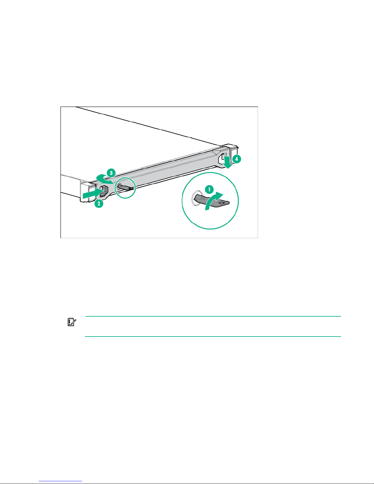
3. For a server using a non-hot-plug power supply: To prevent the accidental disconnection of the
power cord when sliding the server into and from the rack, secure the power cord through the strain
relief clip:
when not fastened to the rails.
CAUTION: Always plan the rack installation so that the heaviest item is on the bottom
rack. Install the heaviest item first, and continue to populate the rack from the bottom to the top.
WARNING:
telephone or telecommunications connectors into RJ-45 connectors.
Setup 30
Page 31

a.
If the clip is positioned too near the power cord that it blocks the power cord plug connection,
slide the clip backward.
b. Connect the power cord to the server.
c. Press the top part of the clip, and then pull the clip open.
d. Position the power cord inside the clip, and then close the clip.
Setup 31
Page 32

e.
Avoid tight bend radii to prevent damaging the internal wires of a power cord or a
server cable. Never bend power cords and server cables tight enough to cause a crease in the
Slide the clip forward until it is flush against the edge of the power cord plug.
4. For a server using a hot-plug power supply: To prevent accidental power cord disconnection
when sliding the server in and out of the rack, secure the power cord in the strain relief strap attached
to the power input module handle:
a. Unwrap the strain relief strap from the power input module handle.
CAUTION:
sheathing.
b. Bend the plug end of the power cord in the position shown in the following image.
Setup 32
Page 33

c.
the power cord into a grounded (earthed) electrical outlet that is easily accessible at all
laced against
it. Pay particular attention to the plug, electrical outlet, and the point where the cord extends
Secure the power cord with the strain relief strap.
5. Employ best practices to route and manage the power cords and other cables in the server rear
panel.
6. Use the hook-and-loop strap included in the server shipping carton to secure the power cords and
the other rear panel cables to the rack rail. For detailed instructions, see "Installing the rack rail
hook-and-loop strap (on page 33)."
7. Connect the power cord to the power source.
WARNING: To reduce the risk of electric shock or damage to the equipment:
• Do not disable the power cord grounding plug. The grounding plug is an important safety
feature.
• Plug
times.
• Unplug the power cord from the power supply to disconnect power to the equipment.
• Do not route the power cord where it can be walked on or pinched by items p
from the server.
Installing the rack rail hook-and-loop strap
The rack rail hook-and-loop strap can be installed on either the left or right rack rail. Hewlett Packard
Enterprise recommends installing it on the left rack rail for better cable management.
To install the rack rail hook-and-loop strap:
1. Install the server into the rack ("Installing the server into the rack" on page 30).
2. Install the rack rail hook-and-loop strap:
a. Hold the rear panel cables against the rack rail, and then wrap the strap around the rack rail.
CAUTION: To prevent thermal or mechanical obstruction on full-length servers installed in
the rack, the extra length and buckle part of the strap must be facing the outside of the rack rail.
Setup 33
Page 34

b.
Loop the end of the hook-and-loop strap through the buckle.
When multiple hook-and-loop straps are used in the same rack, stagger the strap location, so that
the straps are adjacent to each other when viewed from top to bottom. This positioning will enable
the rack rail to slide easily in and out of the rack.
Installing the operating system
This ProLiant server does not ship with provisioning media. Everything needed to manage and install the
system software and firmware is preloaded on the server.
To operate properly, the server must have a supported operating system installed. For the latest
information on operating system support, see the Hewlett Packard Enterprise website
(http://www.hpe.com/info/supportos). Attempting to run an unsupported operating system can cause
serious and unpredictable results.
To install an operating system on the server, use one of the following methods:
• Intelligent Provisioning—iLO includes Intelligent Provisioning for embedded deployment, updating,
and provisioning capabilities. Intelligent Provisioning can configure the server and install an
operating system.
To install an operating system on the server with Intelligent Provisioning (local or remote):
a. Connect the Ethernet cable between the network connector on the server and a network jack.
b. Press the Power On/Standby button.
c. During server POST, press F10.
d. Complete the initial Preferences and Registration portion of Intelligent Provisioning (on page 96).
e. At the 1 Start screen, click Configure and Install.
f. To finish the installation, follow the onscreen prompts. An Internet connection is required to
update the firmware and systems software.
• Remote deployment installation—To deploy an operating system remotely, use Insight Control
Server Provisioning for an automated solution.
For additional system software and firmware updates, download the Service Pack for ProLiant from the
Hewlett Packard Enterprise website (http://www.hpe.com/servers/spp/download). Software and firmware
must be updated before using the server for the first time, unless any installed software or components
require an older version.
For more information, see "Keeping the system current (on page 103)."
Setup 34
Page 35

For more information on using these installation methods, see the Hewlett Packard Enterprise website
(http://www.hpe.com/info/ilo).
Powering on and selecting boot options in UEFI
Boot Mode
On servers operating in UEFI Boot Mode, the boot controller and boot order are set automatically.
1. Press the Power On/Standby button.
2. During the initial boot:
o To modify the server configuration ROM default settings, press the F9 key in the ProLiant POST
screen to enter the UEFI System Utilities screen. By default, the System Utilities menus are in the
English language.
o If you do not need to modify the server configuration and are ready to install the system software,
press the F10 key to access Intelligent Provisioning.
For more information on automatic configuration, see the UEFI documentation on the Hewlett Packard
Enterprise website (http://www.hpe.com/info/enterprise/docs).
Registering the server
To experience quicker service and more efficient support, register the product at the Hewlett Packard
Enterprise Product Registration website (http://www.hpe.com/info/register).
Setup 35
Page 36

Hardware options installation
Introduction
If more than one option is being installed, read the installation instructions for all the hardware options and
identify similar steps to streamline the installation process.
WARNING: To reduce the risk of personal injury from hot surfaces, allow the drives and the
internal system components to cool before touching them.
CAUTION: To prevent damage to electrical components, properly ground the server before
beginning any installation procedure. Improper grounding can cause electrostatic discharge.
Security bezel option
The security bezel helps prevent unauthorized physical access to the front panel components. Install the
security bezel and then lock it with the key provided with the kit. The security bezel is only supported in
servers that are using the quick-release latch rack ears.
Drive options
The server supports up to two LFF hot-plug or non hot-plug drives and four SFF hot-plug.
The embedded storage controller supports SATA drive installation.
For SAS drive installation, install an HPE Host Bus Adapter or an Smart Array Controller board option. For
more information about product features, specifications, options, configurations, and compatibility, see
the product QuickSpecs on the Hewlett Packard Enterprise website (http://www.hpe.com/info/qs).
Hardware options installation 36
Page 37

Drive installation guidelines
When adding drives to the server, observe the following general guidelines:
• The system automatically sets all device numbers.
• Populate drive bays, based on the drive numbering sequence. Start from the drive bay with the
lowest device number ("Drive numbering" on page 13).
• All drives grouped into the same drive array must meet the following criteria:
o They must be either all SAS or all SATA.
o They must be either all hard drives or all solid state drives.
o For the most efficient use of drive space, the drives must have approximately the same capacity.
Each configuration utility treats every physical drive in an array as if it has the same capacity as
the smallest drive in the array. Any excess capacity of a particular drive cannot be used in the
array and so is unavailable for data storage.
Installing a non-hot-plug drive
CAUTION: To prevent improper cooling and thermal damage, do not operate the server
unless all bays are populated with either a component or a blank.
To install the component:
1. If installed, remove the security bezel (on page 17).
2. Power down the server (on page 17).
3. Remove all power:
a. Disconnect each power cord from the power source.
b. Disconnect each power cord from the server.
4. Remove the drive carrier.
Hardware options installation 37
Page 38

5.
Remove the two metal brackets from the drive carrier.
6. Install the drive in the carrier.
7. Install the drive.
CAUTION: To prevent improper cooling and thermal damage, do not operate the server
unless all bays are populated with either a component or a blank.
8. Connect each power cord to the server.
9. Connect each power cord to the power source.
10. Power up the server (on page 17).
11. If removed, install the security bezel ("Security bezel option" on page 36).
To configure arrays, see the HPE Smart Storage Administrator User Guide on the Hewlett Packard
Enterprise website (http://www.hpe.com/info/smartstorage/docs).
Installing a hot-plug drive
Hardware options installation 38
Page 39

CAUTION: To prevent improper cooling and thermal damage, do not operate the server
unless all bays are populated with either a component or a blank.
To install the component:
1. If installed, remove the security bezel (on page 17).
2. Remove the drive blank.
3. Prepare the drive.
4. Install the drive.
5. Determine the status of the drive from the drive LED definitions ("HPE SmartDrive LED definitions"
on page 15).
6. If removed, install the security bezel ("Security bezel option" on page 36).
To configure arrays, see the HPE Smart Storage Administrator User Guide on the Hewlett Packard
Enterprise website (http://www.hpe.com/info/smartstorage/docs).
Drive cable options
Use these drive cable options to install a Smart Array Controller option.
Hardware options installation 39
Page 40

2 LFF Smart Array Controller Mini-SAS cable option
For more information about product features, specifications, options, configurations, and compatibility,
see the product QuickSpecs on the Hewlett Packard Enterprise website (http://www.hpe.com/info/qs).
To install the component:
1. If installed, remove the security bezel (on page 17).
2. Power down the server (on page 17).
3. Remove all power:
a. Disconnect each power cord from the power source.
b. Disconnect each power cord from the server.
4. Do one of the following:
o Extend the server from the rack (on page 18).
o Remove the server from the rack (on page 19).
5. Remove the access panel (on page 20).
6. Disconnect the existing Mini-SAS cables from the system board and the drive backplane.
7. Remove the existing PCI riser cage ("Remove the PCI riser cage" on page 22).
8. Remove the blank from slot 2 of the riser cage.
9. Install the Smart Array controller.
Hardware options installation 40
Page 41

a.
If installed, remove the air scoop from the controller.
b. If you are planning to install the FBWC, install it now ("Installing the storage controller and FBWC
module options" on page 46).
c. Install the Smart Array controller in slot 2.
10. Connect the Mini-SAS cable to the Smart Array controller.
Hardware options installation 41
Page 42

11.
Align the PCI riser board with the corresponding connector on the system board, and then press
down the riser cage.
CAUTION: To prevent improper cooling and thermal damage, do not operate the server
unless all PCI slots have either an expansion slot cover or an expansion board installed.
12. Connect the Mini-SAS cable to the drive backplane.
13. Install the access panel (on page 21).
14. Do one of the following:
o Slide the server into the rack.
o Install the server into the rack ("Installing the server into the rack" on page 30).
15. Connect each power cord to the server.
16. Connect each power cord to the power source.
17. Power up the server (on page 17).
18. If removed, install the security bezel ("Security bezel option" on page 36).
Hardware options installation 42
Page 43

4 SFF Smart Array Controller Mini-SAS cable option
For more information about product features, specifications, options, configurations, and compatibility,
see the product QuickSpecs on the Hewlett Packard Enterprise website (http://www.hpe.com/info/qs).
To install the component:
1. If installed, remove the security bezel (on page 17).
2. Power down the server (on page 17).
3. Remove all power:
a. Disconnect each power cord from the power source.
b. Disconnect each power cord from the server.
4. Do one of the following:
o Extend the server from the rack (on page 18).
o Remove the server from the rack (on page 19).
5. Remove the access panel (on page 20).
6. Disconnect the existing Mini-SAS cables from the system board and the drive backplane.
7. Remove the existing PCI riser cage ("Remove the PCI riser cage" on page 22).
8. Remove the blank from slot 2 of the riser cage.
9. Install the Smart Array controller.
Hardware options installation 43
Page 44

a.
If installed, remove the air scoop from the controller.
b. If you are planning to install the FBWC, install it now ("Installing the storage controller and FBWC
module options" on page 46).
c. Install the Smart Array controller in slot 2.
10. Connect the Mini-SAS cable to the Smart Array controller.
Hardware options installation 44
Page 45

11.
Align the PCI riser board with the corresponding connector on the system board, and then press
down the riser cage.
CAUTION: To prevent improper cooling and thermal damage, do not operate the server
unless all PCI slots have either an expansion slot cover or an expansion board installed.
12. Connect the Mini-SAS cable to the drive backplane.
13. Install the access panel (on page 21).
14. Do one of the following:
o Slide the server into the rack.
o Install the server into the rack ("Installing the server into the rack" on page 30).
15. Connect each power cord to the server.
16. Connect each power cord to the power source.
17. Power up the server (on page 17).
18. If removed, install the security bezel ("Security bezel option" on page 36).
Hardware options installation 45
Page 46

Controller options
remove the battery pack while an array capacity expansion, RAID level migration, or stripe size
The server ships with an embedded Dynamic Smart Array B140i Controller. For more information about
the controller and its features, see the Dynamic Smart Array B140i RAID Controller User Guide on the
Hewlett Packard Enterprise website (http://www.hpe.com/info/smartstorage/docs).
Upgrade options exist for an integrated array controller. For a list of supported options, see the product
QuickSpecs on the Hewlett Packard Enterprise website (http://www.hpe.com/info/qs).
To configure arrays, see the HPE Smart Storage Administrator User Guide on the Hewlett Packard
Enterprise website (http://www.hpe.com/info/smartstorage/docs).
The server supports FBWC. FBWC consists of a cache module and an Smart Storage Battery Pack. The
DDR cache module buffers and stores data being written by an integrated Gen9 P-series Smart Array
Controller.
This server supports the 96-W Smart Storage Battery Pack. This battery pack can support up to 24
devices. Devices in this context refer to the Smart Array Controller or NVDIMM associated with the cache
module.
The battery pack might have a low charge when installed. If the battery does have low charge, a POST
error message appears when the server is powered up, indicating that the battery pack is temporarily
disabled. No action is necessary. The internal circuitry automatically recharges the batteries and enables
the battery pack. When the system is powered on this process might take approximately 2 hours.
If a system power failure occurs, a fully charged battery pack provides power for up to 150 seconds.
During that interval, the controller transfers the cached data from DDR memory to flash memory, where
the data remains indefinitely or until a controller retrieves the data. The data protection and the time limit
also apply if a power outage occurs. When power is restored to the system, an initialization process writes
the preserved data to the storage drives.
CAUTION: The cache module connector does not use the industry-standard DDR3
mini-DIMMs. Do not use the controller with cache modules designed for other controller
models, because the controller can malfunction and you can lose data. Also, do not transfer
this cache module to an unsupported controller model, because you can lose data.
CAUTION: To prevent a server malfunction or damage to the equipment, do not add or
migration is in progress.
CAUTION: After the server is powered down, wait for 30 seconds, and then check the amber
LED before unplugging the cable from the cache module. If the amber LED flashes after 30
seconds, do not remove the cable from the cache module. The cache module is backing up
data. Data will be lost if the cable is detached when the amber LED is still flashing.
Installing the storage controller and FBWC module options
To install the component:
1. If installed, remove the security bezel (on page 17).
2. Power down the server (on page 17).
3. Remove all power:
a. Disconnect each power cord from the power source.
b. Disconnect each power cord from the server.
4. Do one of the following:
o Extend the server from the rack (on page 18).
o Remove the server from the rack (on page 19).
Hardware options installation 46
Page 47

5.
Remove the access panel (on page 20).
6. Remove the existing PCI riser cage ("Remove the PCI riser cage" on page 22).
7. If you intend to use an FBWC module, install the module on the storage controller.
a. If you are installing a Smart Array P440 Controller, remove the air scoop.
b. Connect the cache module backup power cable to the module.
c. Install the cache module on the storage controller.
Hardware options installation 47
Page 48

8.
the system does not erroneously mark the external drives as failed when the server is powered
Install the Smart Array controller in slot 2.
9. Connect all necessary internal cables to the storage controller. For internal drive cabling information,
see "Storage cabling (on page 81)."
10. Install the PCI riser cage (on page 23).
11. Connect the other end of the storage controller cables to the drive backplane. For internal drive
cabling information, see "Storage cabling (on page 81)."
12. Connect the FBWC cable to the system board. For more information, see "FBWC module cabling
(on page 85)."
13. If you are planning to install the Smart Storage Battery Pack, install it now ("Installing an HPE Smart
Storage Battery" on page 48).
14. Install the access panel (on page 21).
15. Do one of the following:
o Slide the server into the rack.
o Install the server into the rack ("Installing the server into the rack" on page 30).
16. Connect each power cord to the server.
17. Connect each power cord to the power source.
18. Power up the server (on page 17).
19. If removed, install the security bezel ("Security bezel option" on page 36).
20. If you are planning to install new drives, install them now ("Drive options" on page 36).
For more information about the integrated storage controller and its features, select the relevant user
documentation on the Hewlett Packard Enterprise website (http://www.hpe.com/info/smartstorage/docs).
To configure arrays, see the HPE Smart Storage Administrator User Guide on the Hewlett Packard
Enterprise website (http://www.hpe.com/info/smartstorage/docs).
Installing an HPE Smart Storage Battery
For more information about product features, specifications, options, configurations, and compatibility,
see the product QuickSpecs on the Hewlett Packard Enterprise website (http://www.hpe.com/info/qs).
CAUTION: In systems that use external data storage, be sure that the server is the first unit
to be powered down and the last to be powered back up. Taking this precaution ensures that
To install the component:
1. If installed, remove the security bezel (on page 17).
2. Power down the server (on page 17).
3. Remove all power:
up.
Hardware options installation 48
Page 49

a.
Disconnect each power cord from the power source.
b. Disconnect each power cord from the server.
4. Do one of the following:
o Extend the server from the rack (on page 18).
o Remove the server from the rack (on page 19).
5. Remove the access panel (on page 20).
6. Remove the air baffle (on page 24).
7. Remove the slot covers.
8. Install the Smart Storage Battery holders.
Hardware options installation 49
Page 50

9.
Install the Smart Storage Battery, and then connect the battery cable to the system board connector.
10. Install the air baffle (on page 24).
11. Install the access panel (on page 21).
12. Do one of the following:
o Slide the server into the rack.
o Install the server into the rack ("Installing the server into the rack" on page 30).
13. Connect each power cord to the server.
14. Connect each power cord to the power source.
15. Power up the server (on page 17).
16. If removed, install the security bezel ("Security bezel option" on page 36).
M.2 SSD SATA cable and optical drive extension
power cable option
Installing one M.2 SSD and one optical drive
For more information about product features, specifications, options, configurations, and compatibility,
see the product QuickSpecs on the Hewlett Packard Enterprise website (http://www.hpe.com/info/qs).
To install the component:
1. If installed, remove the security bezel (on page 17).
2. Power down the server (on page 17).
3. Remove all power:
a. Disconnect each power cord from the power source.
b. Disconnect each power cord from the server.
4. Do one of the following:
o Extend the server from the rack (on page 18).
o Remove the server from the rack (on page 19).
5. Remove the access panel (on page 20).
Hardware options installation 50
Page 51

6.
Remove the optical drive blank.
7. Install the optical drive and secure it with the screw provided in the optical drive kit.
8. Connect and route the cables:
a. Connect the cable assembly from the optical drive option kit to the rear of the optical drive.
b. Connect the power cable to the optical drive extension power cable.
c. Connect the extension cable and the SATA cable to the system board.
Hardware options installation 51
Page 52

— 2 LFF configuration
— 4 SFF configuration
9. Remove the existing PCI riser cage ("Remove the PCI riser cage" on page 22).
10. Select the appropriate PCIe slot to install the M.2 SSD enablement board and remove the PCIe
blank.
Hardware options installation 52
Page 53

o
Slot 1
o Slot 2
11. If installing the M.2 SSD enablement board in slot 1 do the following:
a. Remove the full-height bracket from the M.2 SSD enablement board.
Hardware options installation 53
Page 54

b.
Install the low-profile bracket on the M.2 SSD enablement board.
12. Install the M.2 SSD enablement board into the PCI riser cage, and then connect the SATA cable to
the enablement board.
o Slot 1
o Slot 2
13. Install the PCI riser cage (on page 23).
14. Connect the SATA cable to the SATA connector on the system board.
15. Based on the riser cage configuration, route the M.2 SSD SATA cable in the following ways:
o 2 LFF configuration
Hardware options installation 54
Page 55

— Slot 2 of the FlexibleLOM riser cage assembly
— Slot 1 of the two-slot PCI riser cage assembly
Hardware options installation 55
Page 56

— Slot 2 of the two-slot PCI riser cage assembly
o 4 SFF configuration
— Slot 2 of the FlexibleLOM riser cage assembly
Hardware options installation 56
Page 57

— Slot 1 of the two-slot PCI riser cage assembly
— Slot 2 of the two-slot PCI riser cage assembly
16. Install the access panel (on page 21).
17. Do one of the following:
o Slide the server into the rack.
o Install the server into the rack ("Installing the server into the rack" on page 30).
18. Connect each power cord to the server.
19. Connect each power cord to the power source.
20. Power up the server (on page 17).
21. If removed, install the security bezel ("Security bezel option" on page 36).
Installing two M.2 SSDs
For more information about product features, specifications, options, configurations, and compatibility,
see the product QuickSpecs on the Hewlett Packard Enterprise website (http://www.hpe.com/info/qs).
Hardware options installation 57
Page 58

To install the component:
1. If installed, remove the security bezel (on page 17).
2. Power down the server (on page 17).
3. Remove all power:
a. Disconnect each power cord from the power source.
b. Disconnect each power cord from the server.
4. Do one of the following:
o Extend the server from the rack (on page 18).
o Remove the server from the rack (on page 19).
5. Remove the access panel (on page 20).
6. Remove the existing PCI riser cage ("Remove the PCI riser cage" on page 22).
7. Select the appropriate PCIe slot to install the M.2 SSD enablement board and remove the PCIe
blank.
o Slot 1
o Slot 2
8. If installing the M.2 SSD enablement board in slot 1 do the following:
Hardware options installation 58
Page 59

a.
Remove the full-height bracket from the M.2 SSD enablement board.
b. Install the low-profile bracket on the M.2 SSD enablement board.
9. Install the M.2 SSD enablement board into the PCI riser cage, and then connect the SATA cables to
the enablement board.
o Slot 1
Hardware options installation 59
Page 60

o
Slot 2
10. Install the PCI riser cage (on page 23).
11. Connect the SATA cables to the SATA connectors on the system board.
12. Based on riser cage configuration, route the M.2 SSD SATA cables in the following ways:
o 2 LFF configuration
— Slot 2 of the FlexibleLOM riser cage assembly
Hardware options installation 60
Page 61

— Slot 1 of the two-slot PCI riser cage assembly
— Slot 2 of the two-slot PCI riser cage assembly
o 4 SFF configuration
Hardware options installation 61
Page 62

— Slot 2 of the FlexibleLOM riser cage assembly
— Slot 1 of the two-slot PCI riser cage assembly
Hardware options installation 62
Page 63

Type
Rank
Capacity
Native speed
Voltage
UDIMM
Single
4 GB
2133 MT/s
STD
UDIMM
Single
8 GB
2133 MT/s
STD
UDIMM
Dual
8 GB
2133 MT/s
STD
UDIMM
Dual
16 GB
2133 MT/s
STD
UDIMM
Single
2133 MT/s
2133 MT/s
UDIMM
Dual
2133 MT/s
2133 MT/s
— Slot 2 of the two-slot PCI riser cage assembly
13. Install the access panel (on page 21).
14. Do one of the following:
o Slide the server into the rack.
o Install the server into the rack ("Installing the server into the rack" on page 30).
15. Connect each power cord to the server.
16. Connect each power cord to the power source.
17. Power up the server (on page 17).
18. If removed, install the security bezel ("Security bezel option" on page 36).
Memory options
The memory subsystem in this server supports UDIMMs only.
The server supports the single-rank and dual-rank PC4-2133 (DDR4-2133) UDIMMs operating at up to
2133 MT/s DIMM speeds.
Supported DIMM specifications
Populated DIMM speed (MT/s)
Type Rank 1 DIMM per channel
2 DIMMs per
channel
Hardware options installation 63
Page 64

Memory subsystem architecture
A C 3
B D 1
The memory subsystem in this server is divided into channels. Each processor supports four channels,
and each channel supports two DIMM slots.
Channel Population order Slot number
1
2
4
2
For the location of the slot numbers, see "DIMM slot locations (on page 12)."
This multi-channel architecture provides enhanced performance in Advanced ECC mode.
DIMM slots in this server are identified by number and by letter. Letters identify the population order. Slot
numbers indicate the DIMM slot ID for spare replacement.
Single-, dual-, and quad-rank DIMMs
To understand and configure memory protection modes properly, an understanding of single-, dual-, and
quad-rank DIMMs is helpful. Some DIMM configuration requirements are based on these classifications.
A single-rank DIMM has one set of memory chips that is accessed while writing to or reading from the
memory. A dual-rank DIMM is similar to having two single-rank DIMMs on the same module, with only one
rank accessible at a time. A quad-rank DIMM is, effectively, two dual-rank DIMMs on the same module.
Only one rank is accessible at a time. The server memory control subsystem selects the proper rank
within the DIMM when writing to or reading from the DIMM.
Dual- and quad-rank DIMMs provide the greatest capacity with the existing memory technology. For
example, if current DRAM technology supports 8-GB single-rank DIMMs, a dual-rank DIMM would be 16
GB, and a quad-rank DIMM would be 32 GB.
LRDIMMs are labeled as quad-rank DIMMs. There are four ranks of DRAM on the DIMM, but the
LRDIMM buffer creates an abstraction that allows the DIMM to appear as a dual-rank DIMM to the
system. The LRDIMM buffer isolates the electrical loading of the DRAM from the system to allow for faster
operation. This allows higher memory operating speed compared to quad-rank RDIMMs.
DIMM identification
To determine DIMM characteristics, use the label attached to the DIMM and the following illustration and
table.
Hardware options installation 64
Page 65

Capacity
8 GB
Rank
1R = Single-rank
Data width
x4 = 4-bit
Memory generation
DDR4
Maximum memory
speed
2133 MT/s
6
CAS latency
P=15
DIMM type
R = RDIMM (registered)
UDIMM
Single-rank (4 GB)
16 GB
UDIMM
Single-rank (8 GB)
32 GB
UDIMM
Dual-rank (8 GB)
32 GB
UDIMM
Dual-rank (16 GB)
64 GB
Item Description Definition
1
16 GB
32 GB
2
2R = Dual-rank
4R = Quad-rank
3
x8 = 8-bit
4
5
7
L = LRDIMM (load reduced)
E = UDIMM (unbuffered with ECC)
For more information about product features, specifications, options, configurations, and compatibility,
see the product QuickSpecs on the Hewlett Packard Enterprise website (http://www.hpe.com/info/qs).
Memory configurations
To optimize server availability, the server supports Advanced ECC AMP mode:
• Advanced ECC—Provides up to 4-bit error correction. This mode is the default option for this server.
Advanced Memory Protection options are configured in the BIOS/Platform Configuration (RBSU). If the
requested AMP mode is not supported by the installed DIMM configuration, the server boots in Advanced
ECC mode. For more information, see the HPE UEFI System Utilities User Guide for HPE ProLiant Gen9
Servers on the Hewlett Packard Enterprise website (http://www.hpe.com/info/ProLiantUEFI/docs).
Maximum memory capacity
DIMM type DIMM rank One Processor
For the latest memory configuration information, see the product QuickSpecs on the Hewlett Packard
Enterprise website (http://www.hpe.com/info/docs).
Advanced ECC memory configuration
Advanced ECC memory is the default memory protection mode for this server. Standard ECC can correct
single-bit memory errors and detect multi-bit memory errors. When multi-bit errors are detected using
Standard ECC, the error is signaled to the server and causes the server to halt.
Advanced ECC protects the server against some multi-bit memory errors. Advanced ECC can correct
both single-bit memory errors and 4-bit memory errors if all failed bits are on the same DRAM device on
the DIMM.
Advanced ECC provides additional protection over Standard ECC because it is possible to correct certain
memory errors that would otherwise be uncorrected and result in a server failure. Using HPE Advanced
Memory Error Detection technology, the server provides notification when a DIMM is degrading and has a
higher probability of uncorrectable memory error.
Hardware options installation 65
Page 66

General DIMM slot population guidelines
(per channel)
(MT/s)
1
Single, dual or quad-rank
2133
2
Single, dual or quad-rank
2133
Observe the following guidelines for all AMP modes:
• Install DIMMs only if the corresponding processor is installed.
• Do not mix LRDIMMs and RDIMMs.
• White DIMM slots denote the first slot of a channel (Ch 1-A, Ch 2-B, Ch 3-C, Ch 4-D).
• When only one processor is installed, install DIMMs in sequential alphabetic order: A, B, C, D, E, F,
and so forth.
• When two processors are installed, install the DIMMs in sequential alphabetical order balanced
between the two processors: P1-A, P2-A, P1-B, P2-B, P1-C, P2-C, and so forth.
• When single-rank, dual-rank, and quad-rank DIMMs are populated for two DIMMs per channel,
always populate the higher number rank DIMM first (starting from the farthest slot). For example, first
quad-rank DIMM, then dual-rank DIMM, and then lastly single-rank DIMM.
• DIMMs should be populated starting farthest from the processor on each channel.
For more information about server memory, see the Hewlett Packard Enterprise website
(http://www.hpe.com/info/memory).
The DIMM speeds supported in this server are listed in the following table:
Populated slots
Rank
Speeds supported
Advanced ECC population guidelines
For Advanced ECC mode configurations, observe the following guidelines:
• Observe the general DIMM slot population guidelines.
• DIMMs may be installed individually.
Installing a DIMM
1. If installed, remove the security bezel (on page 17).
2. Power down the server (on page 17).
3. Remove all power:
a. Disconnect each power cord from the power source.
b. Disconnect each power cord from the server.
4. Do one of the following:
o Extend the server from the rack (on page 18).
o Remove the server from the rack (on page 19).
5. Remove the access panel (on page 20).
6. Remove the air baffle (on page 24).
7. Open the DIMM slot latches.
Hardware options installation 66
Page 67

8.
Install the DIMM.
9. Install the air baffle (on page 24).
10. Install the access panel (on page 21).
11. Do one of the following:
o Slide the server into the rack.
o Install the server into the rack ("Installing the server into the rack" on page 30).
12. Connect each power cord to the server.
13. Connect each power cord to the power source.
14. Power up the server (on page 17).
15. If removed, install the security bezel ("Security bezel option" on page 36).
After installing the DIMMs, use BIOS/Platform Configuration (RBSU) in the UEFI System Utilities ("HPE
UEFI System Utilities" on page 98) to configure the memory protection mode.
FlexibleLOM riser cage assembly
For more information on the riser board slot specifications, see "PCIe riser board slot definitions (on page
10)."
For more information about product features, specifications, options, configurations, and compatibility,
see the product QuickSpecs on the Hewlett Packard Enterprise website (http://www.hpe.com/info/qs).
To install the component:
1. If installed, remove the security bezel (on page 17).
2. Power down the server (on page 17).
3. Remove all power:
a. Disconnect each power cord from the power source.
b. Disconnect each power cord from the server.
4. Do one of the following:
o Extend the server from the rack (on page 18).
o Remove the server from the rack (on page 19).
5. Remove the access panel (on page 20).
6. Remove the existing PCI riser cage ("Remove the PCI riser cage" on page 22).
Hardware options installation 67
Page 68

7.
Using a T-10 screwdriver, remove the blank from the FlexbleLOM slot of the riser cage.
Retain the blank for future use.
8. Install the FlexibleLOM adapter:
a. Firmly seat the FlexibleLOM adapter in the slot.
b. Secure the FlexibleLOM adapter with a T-10 screw.
9. Install the PCI riser cage (on page 23).
CAUTION: To prevent improper cooling and thermal damage, do not operate the server
unless all PCI slots have either an expansion slot cover or an expansion board installed.
10. Install the access panel (on page 21).
11. Do one of the following:
o Slide the server into the rack.
o Install the server into the rack ("Installing the server into the rack" on page 30).
12. Connect each power cord to the server.
13. Connect each power cord to the power source.
14. Power up the server (on page 17).
15. If removed, install the security bezel ("Security bezel option" on page 36).
GPU riser cage assembly
For more information on the riser board slot specifications, see "PCIe riser board slot definitions (on page
10)."
For more information about product features, specifications, options, configurations, and compatibility,
see the product QuickSpecs on the Hewlett Packard Enterprise website (http://www.hpe.com/info/qs).
To install the component:
Hardware options installation 68
Page 69

1.
If installed, remove the security bezel (on page 17).
2. Power down the server (on page 17).
3. Remove all power:
a. Disconnect each power cord from the power source.
b. Disconnect each power cord from the server.
4. Do one of the following:
o Extend the server from the rack (on page 18).
o Remove the server from the rack (on page 19).
5. Remove the access panel (on page 20).
6. Remove the existing PCI riser cage ("Remove the PCI riser cage" on page 22).
7. Remove the PCI blank.
Retain the blank for future use.
8. Install the component:
a. Firmly seat the GPU in the slot.
b. Secure the GPU with a T-10 screw.
9. Install the PCI riser cage (on page 23).
CAUTION: To prevent improper cooling and thermal damage, do not operate the server
unless all PCI slots have either an expansion slot cover or an expansion board installed.
10. Install the access panel (on page 21).
11. Do one of the following:
o Slide the server into the rack.
o Install the server into the rack ("Installing the server into the rack" on page 30).
12. Connect each power cord to the server.
Hardware options installation 69
Page 70

13.
Connect each power cord to the power source.
14. Power up the server (on page 17).
15. If removed, install the security bezel ("Security bezel option" on page 36).
Two-slot PCI riser cage assembly
For more information on the riser board slot specifications, see "PCIe riser board slot definitions (on page
10)."
For more information about product features, specifications, options, configurations, and compatibility,
see the product QuickSpecs on the Hewlett Packard Enterprise website (http://www.hpe.com/info/qs).
To install the component:
1. If installed, remove the security bezel (on page 17).
2. Power down the server (on page 17).
3. Remove all power:
a. Disconnect each power cord from the power source.
b. Disconnect each power cord from the server.
4. Do one of the following:
o Extend the server from the rack (on page 18).
o Remove the server from the rack (on page 19).
5. Remove the access panel (on page 20).
6. Remove the existing PCI riser cage ("Remove the PCI riser cage" on page 22).
7. Remove the blank and T-10 screw from the slot of the riser cage.
o Slot 1
o Slot 2
Retain the blank for future use.
8. Install the expansion board and secure it with a screw.
Hardware options installation 70
Page 71

NOTE: If expansion board installed with full-height support bracket, replace with low-profile
support bracket in the expansion board kit.
o Slot 1
o Slot 2
9. Connect all necessary internal cabling to the expansion board. For more information on these
cabling requirements, see the documentation that ships with the option.
10. Install the PCI riser cage (on page 23).
CAUTION: To prevent improper cooling and thermal damage, do not operate the server
unless all PCI slots have either an expansion slot cover or an expansion board installed.
11. Install the access panel (on page 21).
12. Do one of the following:
o Slide the server into the rack.
o Install the server into the rack ("Installing the server into the rack" on page 30).
13. Connect each power cord to the server.
14. Connect each power cord to the power source.
15. Power up the server (on page 17).
16. If removed, install the security bezel ("Security bezel option" on page 36).
Redundant power supply option
Hardware options installation 71
Page 72

WARNING: To reduce the risk of electric shock or damage to the equipment:
Plug the power cord into a grounded (earthed) electrical outlet that is easily accessible at all
or pinched by items placed against
it. Pay particular attention to the plug, electrical outlet, and the point where the cord extends
• Do not disable the power cord grounding plug. The grounding plug is an important safety
feature.
•
times.
• Unplug the power cord from the power supply to disconnect power to the equipment.
• Do not route the power cord where it can be walked on
from the equipment.
WARNING: To reduce the risk of injury from electric shock hazards, do not open power
supplies. Refer all maintenance, upgrades, and servicing to qualified personnel.
WARNING: To reduce the risk of personal injury from hot surfaces, allow the drives and the
internal system components to cool before touching them.
CAUTION: To prevent damage to electrical components, properly ground the server before
beginning any installation procedure. Improper grounding can cause ESD.
For more information about product features, specifications, options, configurations, and compatibility,
see the product QuickSpecs on the Hewlett Packard Enterprise website (http://www.hpe.com/info/qs).
To install the component:
1. If installed, remove the security bezel (on page 17).
2. Power down the server (on page 17).
3. Release the power cords from the strain relief straps.
4. Remove all power:
a. Disconnect each power cord from the power source.
b. Disconnect each power cord from the server.
5. Do one of the following:
o Extend the server from the rack (on page 18).
o Remove the server from the rack (on page 19).
6. Remove the access panel (on page 20).
Hardware options installation 72
Page 73

7.
Remove the air baffle (on page 24).
8. If installed, remove the Smart Storage Battery.
9. Remove the Smart Storage Battery holders:
a. Lift the chassis to access the bottom and push the latch of each holder.
Hardware options installation 73
Page 74

b.
Remove the Smart Storage Battery holders.
10. Remove the existing power supply.
11. Install a hot-plug power input module in power supply bay 1.
Hardware options installation 74
Page 75

12.
Install the RPS backplane in the server.
13. Connect the adapter cables.
14. If you intend to enable power redundancy in the server, install a second power input module in power
supply bay 2:
Hardware options installation 75
Page 76

a.
Avoid tight bend radii to prevent damaging the internal wires of a power cord or a
and server cables tight enough to cause a crease in the
Remove the power supply blank.
b. Install a hot-plug power input module in power supply bay 2.
15. To prevent accidental power cord disconnection when sliding the server in and out of the rack,
secure the power cord in the strain relief strap attached to the power input module handle:
a. Unwrap the strain relief strap from the power input module handle.
CAUTION:
server cable. Never bend power cords
sheathing.
b. Bend the plug end of the power cord in the position shown in the following image.
Hardware options installation 76
Page 77

rver is extended from
c.
Secure the power cord with the strain relief strap.
16. Employ best practices to route and manage the power cords and other cables in the server rear
panel.
IMPORTANT: When using cable management arm components, be sure to leave enough
slack in each of the cables to prevent damage to the cables when the se
17. If removed, install the Smart Storage Battery holders ("Installing an HPE Smart Storage Battery" on
the rack.
page 48).
18. If removed, install the Smart Storage Battery and connect the cable to the system board ("Installing
an HPE Smart Storage Battery" on page 48).
19. Install the air baffle (on page 24).
20. Install the access panel (on page 21).
21. Do one of the following:
o Slide the server into the rack.
o Install the server into the rack ("Installing the server into the rack" on page 30).
22. Connect each power cord to the server.
23. Connect each power cord to the power source.
24. Power up the server (on page 17).
25. If removed, install the security bezel ("Security bezel option" on page 36).
HPE Trusted Platform Module option
For more information about product features, specifications, options, configurations, and compatibility,
see the product QuickSpecs on the Hewlett Packard Enterprise website (http://www.hpe.com/info/qs).
Use these instructions to install and enable a TPM on a supported server. This procedure includes three
sections:
1. Installing the Trusted Platform Module board (on page 78).
2. Retaining the recovery key/password (on page 79).
3. Enabling the Trusted Platform Module (on page 80).
Enabling the TPM requires accessing BIOS/Platform Configuration (RBSU) in UEFI System Utilities
("HPE UEFI System Utilities" on page 98).
Hardware options installation 77
Page 78

TPM installation requires the use of drive encryption technology, such as the Microsoft Windows
TPM, administrators should consider the system compromised and take appropriate measures
BitLocker Drive Encryption feature. For more information on BitLocker, see the Microsoft website
(http://www.microsoft.com).
CAUTION: Always observe the guidelines in this document. Failure to follow these
guidelines can cause hardware damage or halt data access.
When installing or replacing a TPM, observe the following guidelines:
• Do not remove an installed TPM. Once installed, the TPM becomes a permanent part of the system
board.
• When installing or replacing hardware, Hewlett Packard Enterprise service providers cannot enable
the TPM or the encryption technology. For security reasons, only the customer can enable these
features.
• When returning a system board for service replacement, do not remove the TPM from the system
board. When requested, Hewlett Packard Enterprise Service provides a TPM with the spare system
board.
• Any attempt to remove an installed TPM from the system board breaks or disfigures the TPM
security rivet. Upon locating a broken or disfigured rivet on an installed TPM, administrators should
consider the system compromised and take appropriate measures to ensure the integrity of the
system data.
• When using BitLocker, always retain the recovery key/password. The recovery key/password is
required to enter Recovery Mode after BitLocker detects a possible compromise of system integrity.
• Hewlett Packard Enterprise is not liable for blocked data access caused by improper TPM use. For
operating instructions, see the encryption technology feature documentation provided by the
Installing the Trusted Platform Module board
operating system.
WARNING: To reduce the risk of personal injury from hot surfaces, allow the drives and the
internal system components to cool before touching them.
1. If installed, remove the security bezel (on page 17).
2. Power down the server (on page 17).
3. Remove all power:
a. Disconnect each power cord from the power source.
b. Disconnect each power cord from the server.
4. Do one of the following:
o Extend the server from the rack (on page 18).
o Remove the server from the rack (on page 19).
5. Remove the access panel (on page 20).
6. Remove the PCI riser cage (on page 22).
CAUTION: Any attempt to remove an installed TPM from the system board breaks or
disfigures the TPM security rivet. Upon locating a broken or disfigured rivet on an installed
to ensure the integrity of the system data.
Hardware options installation 78
Page 79

7.
Install the TPM board. Press down on the connector to seat the board ("System board components"
on page 11).
8. Install the TPM security rivet by pressing the rivet firmly into the system board.
9. If removed, install the PCI riser cage (on page 23).
10. Install the access panel (on page 21).
11. Do one of the following:
o Slide the server into the rack.
o Install the server into the rack ("Installing the server into the rack" on page 30).
12. Connect each power cord to the server.
13. Connect each power cord to the power source.
14. Power up the server (on page 17).
15. If removed, install the security bezel ("Security bezel option" on page 36).
Retaining the recovery key/password
The recovery key/password is generated during BitLocker setup, and can be saved and printed after
BitLocker is enabled. When using BitLocker, always retain the recovery key/password. The recovery
Hardware options installation 79
Page 80

key/password is required to enter Recovery Mode after BitLocker detects a possible compromise of
When a TPM is installed and enabled on the server, data access is locked if you
system integrity.
To help ensure maximum security, observe the following guidelines when retaining the recovery
key/password:
• Always store the recovery key/password in multiple locations.
• Always store copies of the recovery key/password away from the server.
• Do not save the recovery key/password on the encrypted hard drive.
Enabling the Trusted Platform Module
1. During the server startup sequence, press the F9 key to access System Utilities.
2. From the System Utilities screen, select System Configuration > BIOS/Platform Configuration
(RBSU) > Server Security.
3. Select Trusted Platform Module Options and press the Enter key.
4. Select Enabled to enable the TPM and BIOS secure startup. The TPM is fully functional in this
mode.
5. Press the F10 key to save your selection.
6. When prompted to save the change in System Utilities, press the Y key.
7. Press the ESC key to exit System Utilities. Then, press the Enter key when prompted to reboot the
server.
The server then reboots a second time without user input. During this reboot, the TPM setting becomes
effective.
You can now enable TPM functionality in the OS, such as Microsoft Windows BitLocker or measured
boot.
CAUTION:
fail to follow the proper procedures for updating the system or option firmware, replacing the
For more information on firmware updates and hardware procedures, see the Trusted Platform Module
Best Practices White Paper on the Hewlett Packard Enterprise Support Center website
(http://www.hpe.com/support/hpesc).
system board, replacing a hard drive, or modifying OS application TPM settings.
For more information on adjusting TPM usage in BitLocker, see the Microsoft website
(http://technet.microsoft.com/en-us/library/cc732774.aspx).
Hardware options installation 80
Page 81

Cabling
Item
Description
1
Mini-SAS cable
2
Drive power cable
Cabling overview
This section provides guidelines that help you make informed decisions about cabling the server and
hardware options to optimize performance.
For information on cabling peripheral components, refer to the white paper on high-density deployment at
the Hewlett Packard Enterprise website (http://www.hpe.com/products/servers/platforms).
CAUTION: When routing cables, always be sure that the cables are not in a position where
they can be pinched or crimped.
Storage cabling
2-bay LFF non-hot-plug drive cabling
Cabling 81
Page 82

2-bay LFF hot-plug drive cabling
1
Mini-SAS cable
2
Drive power cable
Item
Description
1
Mini-SAS cable
2
Drive power cable
Item Description
4-bay SFF hot-plug drive cabling
M.2 SSD cabling
• Single M.2 SSD SATA cabling
Cabling 82
Page 83

NOTE: M.2 SSD cabling is the same for both LFF and SFF configurations.
o 2 LFF configuration
— Slot 2 of the FlexibleLOM riser cage assembly
— Slot 1 of the two-slot PCI riser cage assembly
Cabling 83
Page 84

— Slot 2 of the two-slot PCI riser cage assembly
1
M.2 SSD 1 SATA cable
2
M.2 SSD 2 SATA cable
• Dual M.2 SSD SATA cabling
NOTE: M.2 SSD cabling is the same for both LFF and SFF configurations.
o 2 LFF configuration
— Slot 2 of the FlexibleLOM riser cage assembly
Item Description
Cabling 84
Page 85

— Slot 1 of the two-slot PCI riser cage assembly
1
M.2 SSD 1 SATA cable
2
M.2 SSD 2 SATA cable
1
M.2 SSD 1 SATA cable
2
M.2 SSD 2 SATA cable
Item Description
— Slot 2 of the two-slot PCI riser cage assembly
Item Description
FBWC module cabling
The FBWC solution is a separately purchased option. This server only supports FBWC module
installation ("Installing the storage controller and FBWC module options" on page 46) when a Smart Array
P-Series controller is installed.
Cabling 85
Page 86

Depending on the controller option installed, the actual storage controller connectors might look different
from what is shown in this section.
Smart Storage Battery cabling
Cabling 86
Page 87

H240 Host Bus Adapter cabling
• 2-bay LFF hot-plug configuration
• 4-bay SFF hot-plug configuration
Cabling 87
Page 88

• 2-bay LFF non-hot-plug configuration
Optical drive cabling
• 2 LFF configuration
Cabling 88
Page 89

• 4 SFF configuration
Item
Description
1
SATA cable
2
Power cable
3
4-pin to 4-pin power extension cable
Item
Description
1
Fan 3 power cable
2
Fan 3 power extension cable
3
Fan 2 power cable
4
Fan 1 power cable
Fan cabling
Cabling 89
Page 90

Power supply cabling
Item
Description
1
14-pin power cable
2
16-pin power supply sideband signal cable
1
24-pin power cable
2
24-pin to 14-pin power extension cable
3
Power supply sideband extension cable
HPE 290 W non-hot-plug power supply cabling
Redundant Power Supply backplane cabling
Item Description
Cabling 90
Page 91

Item Description
4
16-pin power supply sideband signal cable
Front I/O cabling
P440 Smart Array Controller cabling
• 4-bay SFF hot-plug drive configuration
Cabling 91
Page 92

• 2-bay LFF hot-plug drive configuration
Cabling 92
Page 93

Software and configuration utilities
Online and Offline
Online and Offline
RESTful API support for iLO (on page 95)
Online and Offline
Integrated Management Log (on page 95)
Online and Offline
Online
HPE Insight Online ("Insight Online" on page 96)
Online
Intelligent Provisioning (on page 96)
Offline
HPE Insight Diagnostics (on page 97)
Online and Offline
Erase Utility (on page 97)
Offline
Online
Service Pack for ProLiant (on page 98)
Online and Offline
HP Smart Update Manager (on page 98)
Online and Offline
HPE UEFI System Utilities (on page 98)
Offline
HPE Smart Storage Administrator (on page 101)
Online and Offline
Offline
Server mode
The software and configuration utilities presented in this section operate in online mode, offline mode, or
in both modes.
Software or configuration utility Server mode
HPE iLO
Active Health System (on page 94)
HPE Insight Remote Support (on page 95)
Scripting Toolkit for Windows and Linux (on page 98)
FWUPDATE utility (on page 103)
Product QuickSpecs
For more information about product features, specifications, options, configurations, and compatibility,
see the product QuickSpecs on the Hewlett Packard Enterprise website (http://www.hpe.com/info/qs).
HPE iLO
The iLO 4 subsystem is a standard component of ProLiant servers that simplifies initial server setup,
server health monitoring, power and thermal optimization, and remote server administration. The iLO
subsystem includes an intelligent microprocessor, secure memory, and a network interface. This design
makes iLO independent of the host server and its operating system.
The iLO enables and manages the Active Health System (on page 94) and also features Agentless
Management. All key internal subsystems are monitored by iLO. If enabled, SNMP alerts are sent directly
by iLO regardless of the host operating system or even if no host operating system is installed.
Embedded remote support software is available on ProLiant Gen8 and later servers with iLO 4 regardless
of the operating system software and without installing OS agents on the server.
Using iLO, you can do the following:
Software and configuration utilities 93
Page 94

• Access a high-performance and secure Integrated Remote Console to the server from anywhere in
the world if you have a network connection to the server.
• Use the shared .NET Integrated Remote Console to collaborate with up to four server administrators.
• Remotely mount high-performance Virtual Media devices to the server.
• Securely and remotely control the power state of the managed server.
• Implement true Agentless Management with SNMP alerts from iLO, regardless of the state of the
host server.
• Download the Active Health System log.
• Register for Insight Remote Support.
• Use iLO Federation to manage multiple servers from one system running the iLO web interface.
• Use Virtual Power and Virtual Media from the GUI, the CLI, or the iLO scripting toolkit for many tasks,
including the automation of deployment and provisioning.
• Control iLO by using a remote management tool.
For more information about iLo features, see the iLo documentation on the Hewlett Packard Enterprise
website (http://www.hpe.com/info/ilo/docs).
The iLO 4 hardware and firmware features and functionality, such as NAND size and embedded user
partition, vary depending on the server model. For a complete list of supported features and functionality,
see the iLO 4 QuickSpecs on the Hewlett Packard Enterprise website
(http://www.hpe.com/info/Quickspecs-iLO).
Active Health System
The HPE Active Health System provides the following features:
• Combined diagnostics tools/scanners
• Always on, continuous monitoring for increased stability and shorter downtimes
• Rich configuration history
• Health and service alerts
• Easy export and upload to Service and Support
The Active Health System monitors and records changes in the server hardware and system
configuration. The Active Health System assists in diagnosing problems and delivering rapid resolution if
server failures occur.
The Active Health System collects the following types of data:
• Server model
• Serial number
• Processor model and speed
• Storage capacity and speed
• Memory capacity and speed
• Firmware/BIOS
Active Health System does not collect information about Active Health System users' operations,
finances, customers, employees, partners, or data center, such as IP addresses, host names, user
names, and passwords. Active Health System does not parse or change operating system data from
third-party error event log activities, such as content created or passed through by the operating system.
Software and configuration utilities 94
Page 95

The data that is collected is managed according to the Hewlett Packard Enterprise Data Privacy policy.
For more information see the Hewlett Packard Enterprise website (http://www.hpe.com/info/privacy).
The Active Health System, in conjunction with the system monitoring provided by Agentless Management
or SNMP Pass-thru, provides continuous monitoring of hardware and configuration changes, system
status, and service alerts for various server components.
The Agentless Management Service is available in the SPP, which can be downloaded from the Hewlett
Packard Enterprise website (http://www.hpe.com/servers/spp/download). The Active Health System log
can be downloaded manually from iLO 4 or HPE Intelligent Provisioning and sent to Hewlett Packard
Enterprise.
For more information, see the following documents:
• iLO User Guide on the Hewlett Packard Enterprise website
(http://www.hpe.com/info/enterprise/docs)
• Intelligent Provisioning User Guide on the Hewlett Packard Enterprise website
(http://www.hpe.com/info/enterprise/docs)
RESTful API support for iLO
HPE iLO 4 firmware version 2.00 and later includes the RESTful API. The RESTful API is a management
interface that server management tools can use to perform configuration, inventory, and monitoring of the
ProLiant server via iLO. A REST client sends HTTPS operations to the iLO web server to GET and
PATCH JSON-formatted data, and to configure supported iLO and server settings, such as the UEFI
BIOS settings.
HPE iLO 4 supports the RESTful API with ProLiant Gen8 and later servers. For more information about
the RESTful API, see the Hewlett Packard Enterprise website
(http://www.hpe.com/support/restfulinterface/docs).
Integrated Management Log
The IML records hundreds of events and stores them in an easy-to-view form. The IML timestamps each
event with 1-minute granularity.
You can view recorded events in the IML in several ways, including the following:
• From within HPE SIM
• From within UEFI System Utilities ("HPE UEFI System Utilities" on page 98)
• From within the Embedded UEFI shell (on page 100)
• From within operating system-specific IML viewers:
o For Windows: IML Viewer
o For Linux: IML Viewer Application
• From within the iLO web interface
• From within Insight Diagnostics ("HPE Insight Diagnostics" on page 97)
HPE Insight Remote Support
Hewlett Packard Enterprise strongly recommends that you register your device for remote support to
enable enhanced delivery of your Hewlett Packard Enterprise warranty, HP Care Pack Service, or Hewlett
Packard Enterprise contractual support agreement. Insight Remote Support supplements your monitoring
continuously to ensure maximum system availability by providing intelligent event diagnosis, and
automatic, secure submission of hardware event notifications to Hewlett Packard Enterprise, which will
initiate a fast and accurate resolution, based on your product’s service level. Notifications can be sent to
Software and configuration utilities 95
Page 96

your authorized Hewlett Packard Enterprise Channel Partner for onsite service, if configured and
available in your country.
For more information, see Insight Remote Support and Insight Online Setup Guide for ProLiant Servers
and BladeSystem c-Class Enclosures on the Hewlett Packard Enterprise website
(http://www.hpe.com/info/insightremotesupport/docs). Insight Remote Support is available as part of
Warranty, HP Care Pack Service, or contractual support agreement.
HPE Insight Remote Support central connect
When you use the embedded Remote Support functionality with ProLiant Gen8 and later server models
and BladeSystem c-Class enclosures, you can register a server or rack to communicate to Hewlett
Packard Enterprise through an Insight Remote Support centralized Hosting Device in your local
environment. All configuration and service event information is routed through the Hosting Device. This
information can be viewed by using the local Insight Remote Support user interface or the web-based
view in Insight Online.
For more information, see Insight Remote Support Release Notes on the Hewlett Packard Enterprise
website (http://www.hpe.com/info/insightremotesupport/docs).
HPE Insight Online direct connect
When you use the embedded Remote Support functionality with ProLiant Gen8 and later server models
and BladeSystem c-Class enclosures, you can register a server or rack to communicate directly to Insight
Online without the need to set up an Insight Remote Support centralized Hosting Device in your local
environment. Insight Online will be your primary interface for remote support information.
For more information, see the product documentation on the Hewlett Packard Enterprise website
(http://www.hpe.com/info/insightremotesupport/docs).
Insight Online
HPE Insight Online is a capability of the Support Center portal. Combined with Insight Remote Support
central connect or Insight Online direct connect, it automatically aggregates device health, asset, and
support information with contract and warranty information, and then secures it in a single, personalized
dashboard that is viewable from anywhere at any time. The dashboard organizes your IT and service data
to help you understand and respond to that information more quickly. With specific authorization from you,
an authorized Channel Partner can also view your IT environment remotely using Insight Online.
For more information about using Insight Online, see Insight Online User’s Guide on the Hewlett Packard
Enterprise website (http://www.hpe.com/info/enterprise/docs).
Intelligent Provisioning
Intelligent Provisioning is a single-server deployment tool embedded in ProLiant Gen8 and later servers
that simplifies ProLiant server setup, providing a reliable and consistent way to deploy ProLiant server
configurations:
• Intelligent Provisioning assists with the OS installation process by preparing the system for installing
"off-the-shelf" and Hewlett Packard Enterprise branded versions of operating system software and
integrating optimized ProLiant server support software.
• Intelligent Provisioning provides maintenance-related tasks using the Perform Maintenance window.
• Intelligent Provisioning provides installation help for Microsoft Windows, Red Hat and SUSE Linux,
and VMware operating systems. For specific OS support, see the Intelligent Provisioning Release
Notes on the Hewlett Packard Enterprise website
(http://www.hpe.com/info/intelligentprovisioning/docs).
For more information about Intelligent Provisioning software, see the Hewlett Packard Enterprise website
(http://www.hpe.com/info/intelligentprovisioning/docs). For Intelligent Provisioning recovery media
Software and configuration utilities 96
Page 97

downloads, see the Resources tab on the Hewlett Packard Enterprise website
its original factory state, deletes the current hardware configuration information, including array
tely. Before using this
(http://www.hpe.com/info/ilo). For consolidated drive and firmware update packages, see the Smart
Update: Server Firmware and Driver Updates page on the Hewlett Packard Enterprise website
(http://www.hpe.com/info/SmartUpdate/docs).
HPE Insight Diagnostics
HPE Insight Diagnostics is a proactive server management tool, available in both offline and online
versions, that provides diagnostics and troubleshooting capabilities to assist IT administrators who verify
server installations, troubleshoot problems, and perform repair validation.
HPE Insight Diagnostics Offline Edition performs various in-depth system and component testing while
the OS is not running. To run this utility, boot the server using Intelligent Provisioning (on page 96).
HPE Insight Diagnostics Online Edition is a web-based application that captures system configuration and
other related data needed for effective server management. Available in Microsoft Windows and Linux
versions, the utility helps to ensure proper system operation.
For more information or to download the utility, see the Hewlett Packard Enterprise website
(ftp://ftp.hpe.com). Insight Diagnostics Online Edition is also available in the SPP ("Service Pack for
Insight Diagnostics survey functionality
ProLiant" on page 98).
HPE Insight Diagnostics (on page 97) provides survey functionality that gathers critical hardware and
software information on ProLiant servers.
This functionality supports operating systems that are supported by the server. For operating systems
supported by the server, see the Hewlett Packard Enterprise website
(http://www.hpe.com/info/supportos).
If a significant change occurs between data-gathering intervals, the survey function marks the previous
information and overwrites the survey data files to reflect the latest changes in the configuration.
Survey functionality is installed with every Intelligent Provisioning-assisted HPE Insight Diagnostics
Erase Utility
installation, or it can be installed through the SPP ("Service Pack for ProLiant" on page 98).
CAUTION: Perform a backup before running the Erase Utility. The utility sets the system to
setup and disk partitioning, and erases all connected hard drives comple
utility, see the instructions in the Intelligent Provisioning User Guide.
Use the Erase Utility to erase drives and Active Health System logs, and to reset UEFI System Utilities
settings. Run the Erase Utility if you must erase the system for the following reasons:
• You want to install a new operating system on a server with an existing operating system.
• You encounter an error when completing the steps of a factory-installed operating system
installation.
To access the Erase Utility, click the Perform Maintenance icon from the Intelligent Provisioning home
screen, and then select Erase.
For more information about the Erase Utility, see the Intelligent Provisioning User Guide on the Hewlett
Packard Enterprise website (http://www.hpe.com/info/intelligentprovisioning/docs).
Software and configuration utilities 97
Page 98

Scripting Toolkit for Windows and Linux
The Scripting Toolkit for Windows and Linux is a server deployment product that delivers an unattended
automated installation for high-volume server deployments. The Scripting Toolkit is designed to support
ProLiant BL, ML, DL, SL, and XL servers. The toolkit includes a modular set of utilities and important
documentation that describes how to apply these tools to build an automated server deployment process.
The Scripting Toolkit provides a flexible way to create standard server configuration scripts. These scripts
are used to automate many of the manual steps in the server configuration process. This automated
server configuration process cuts time from each deployment, making it possible to scale rapid,
high-volume server deployments.
For more information, and to download the Scripting Toolkit, see the Hewlett Packard Enterprise website
(http://www.hpe.com/info/ProLiant/STK).
Service Pack for ProLiant
The SPP is a comprehensive systems software (drivers and firmware) solution delivered as a single
package with major server releases. This solution uses HP SUM as the deployment tool and is tested on
all supported ProLiant servers including ProLiant Gen8 and later servers.
SPP can be used in an online mode on a Windows or Linux hosted operating system, or in an offline mode
where the server is booted to an operating system included on the ISO file so that the server can be
updated automatically with no user interaction or updated in interactive mode.
For more information or to download SPP, see one of the following pages on the Hewlett Packard
Enterprise website:
• Service Pack for ProLiant download page (http://www.hpe.com/info/spp/docs)
• Smart Update: Server Firmware and Driver Updates page
(http://www.hpe.com/info/SmartUpdate/docs)
HP Smart Update Manager
HP SUM is a product used to install and update firmware, drivers, and systems software on ProLiant
servers. The HP SUM provides a GUI and a command-line scriptable interface for deployment of systems
software for single or one-to-many ProLiant servers and network-based targets, such as iLOs, OAs, and
VC Ethernet and Fibre Channel modules.
For more information about HP SUM, see the product page on the Hewlett Packard Enterprise website
(http://www.hpe.com/info/hpsum).
To download HP SUM, see the Hewlett Packard Enterprise website
(http://www.hpe.com/info/hpsum/download).
To access the HP Smart Update Manager User Guide, see the HP SUM Information Library
(http://www.hpe.com/info/hpsum/documentation).
HPE UEFI System Utilities
The HPE UEFI System Utilities is embedded in the system ROM. The UEFI System Utilities enable you to
perform a wide range of configuration activities, including:
• Configuring system devices and installed options
• Enabling and disabling system features
• Displaying system information
• Selecting the primary boot controller
Software and configuration utilities 98
Page 99

• Configuring memory options
Action
Key
Access System Utilities
F9 during server POST
Navigate menus
Up and Down arrows
Select items
Enter
Save selections
F10
option*
F1
boot the OS installation if the defaults are restored. To avoid this issue, use
• Selecting a language
• Launching other pre-boot environments such as the Embedded UEFI Shell and Intelligent
Provisioning
For more information on the UEFI System Utilities, see the UEFI System Utilities User Guide for HPE
ProLiant Gen9 Servers on the Hewlett Packard Enterprise website
(http://www.hpe.com/info/ProLiantUEFI/docs).
Scan the QR code located at the bottom of the screen to access mobile-ready online help for the UEFI
System Utilities and UEFI Shell. For on-screen help, press F1.
Using UEFI System Utilities
To use the UEFI System Utilities, use the following keys.
Access Help for a highlighted configuration
*Scan the QR code on the screen to access online help for the UEFI System Utilities and UEFI Shell.
Default configuration settings are applied to the server at one of the following times:
• Upon the first system power-up
• After defaults have been restored
Default configuration settings are sufficient for typical server operations; however, you can modify
configuration settings as needed. The system prompts you for access to the System Utilities each time the
system is powered up.
Flexible boot control
This feature enables you to do the following:
• Add Boot Options
o Browse all FAT16 and FAT32 file systems.
o Select an X64 UEFI application with an .EFI extension to add as a new UEFI boot option, such as
an OS boot loader or other UEFI application.
The new boot option is appended to the boot order list. When you select a file, you are prompted
to enter the boot option description (which is then displayed in the Boot menu), as well as any
optional data to be passed to an .EFI application.
• Boot to System Utilities
After pre-POST, the boot options screen appears. During this time, you can access the System
Utilities by pressing the F9 key.
• Choose between supported modes: Legacy BIOS Boot Mode or UEFI Boot Mode
IMPORTANT: If the default boot mode settings are different than the user defined settings,
the system may not
the User Defined Defaults feature in UEFI System Utilities to override the factory default
settings.
Software and configuration utilities 99
Page 100

For more information, see the UEFI System Utilities User Guide for ProLiant Gen9 Servers on the Hewlett
Packard Enterprise website (http://www.hpe.com/info/ProLiantUEFI/docs).
Restoring and customizing configuration settings
You can reset all configuration settings to the factory default settings, or you can restore system default
configuration settings, which are used instead of the factory default settings.
You can also configure default settings as necessary, and then save the configuration as the custom
default configuration. When the system loads the default settings, it uses the custom default settings
instead of the factory defaults.
Secure Boot configuration
Secure Boot is integrated in the UEFI specification on which the Hewlett Packard Enterprise
implementation of UEFI is based. Secure Boot is completely implemented in the BIOS and does not
require special hardware. It ensures that each component launched during the boot process is digitally
signed and that the signature is validated against a set of trusted certificates embedded in the UEFI BIOS.
Secure Boot validates the software identity of the following components in the boot process:
• UEFI drivers loaded from PCIe cards
• UEFI drivers loaded from mass storage devices
• Pre-boot UEFI shell applications
• OS UEFI boot loaders
Once enabled, only firmware components and operating systems with boot loaders that have an
appropriate digital signature can execute during the boot process. Only operating systems that support
Secure Boot and have an EFI boot loader signed with one of the authorized keys can boot when Secure
Boot is enabled. For more information about supported operating systems, see the UEFI system utilities
and shell release notes on the Hewlett Packard Enterprise website
(http://www.hpe.com/info/ProLiantUEFI/docs).
A physically present user can customize the certificates embedded in the UEFI BIOS by adding/removing
their own certificates.
Embedded UEFI shell
The system BIOS in all ProLiant Gen9 servers includes an Embedded UEFI Shell in the ROM. The UEFI
Shell environment provides an API, a command line prompt, and a set of CLIs that allow scripting, file
manipulation, and system information. These features enhance the capabilities of the UEFI System
Utilities.
For more information, see the following documents:
• UEFI Shell User Guide for ProLiant Gen9 Servers on the Hewlett Packard Enterprise website
(http://www.hpe.com/info/ProLiantUEFI/docs)
• UEFI Shell Specification on the UEFI website (http://www.uefi.org/specifications)
Embedded Diagnostics option
The system BIOS in all ProLiant Gen9 servers includes an Embedded Diagnostics option in the ROM.
The Embedded Diagnostics option can run comprehensive diagnostics of the server hardware, including
processors, memory, drives, and other server components.
For more information on the Embedded Diagnostics option, see the UEFI System Utilities User Guide for
ProLiant Gen9 Servers on the Hewlett Packard Enterprise website
(http://www.hpe.com/info/ProLiantUEFI/docs).
Software and configuration utilities 100
 Loading...