

Page 1

HP ENVY Rove 20 Mobile All-in-One PC
Maintenance and Service Guide
Page 2

© Copyright 2013 Hewlett-Packard
Development Company, L.P.
Bluetooth is a trademark owned by its
proprietor and used by Hewlett-Packard
Company under license. Intel and Core are
trademarks of Intel Corporation in the U.S.
and other countries. Microsoft and Windows
are U.S. registered trademarks of Microsoft
Corporation. SD Logo is a trademark of its
proprietor.
The information contained herein is subject
to change without notice. The only
warranties for HP products and services are
set forth in the express warranty statements
accompanying such products and services.
Nothing herein should be construed as
constituting an additional warranty. HP shall
not be liable for technical or editorial errors
or omissions contained herein.
Second Edition: November 2013
First Edition: June 2013
Document Part Number: 722961-002
Product notice
This guide describes features that are
common to most models. Some features
may not be available on your computer.
Not all features are available in all editions
of Windows 8. This computer may require
upgraded and/or separately purchased
hardware, drivers, and/or software to take
full advantage of Windows 8 functionality.
See
http://www.microsoft.com for details.
Page 3

Safety warning notice
WARNING! To reduce the possibility of heat-related injuries or of overheating the device, do not
place the device directly on your lap or obstruct the device air vents. Use the device only on a hard,
flat surface. Do not allow another hard surface, such as an adjoining optional printer, or a soft
surface, such as pillows or rugs or clothing, to block airflow. Also, do not allow the AC adapter to
contact the skin or a soft surface, such as pillows or rugs or clothing, during operation. The device
and the AC adapter comply with the user-accessible surface temperature limits defined by
the International Standard for Safety of Information Technology Equipment (IEC 60950).
iii
Page 4

iv Safety warning notice
Page 5

Table of contents
1 Product description ........................................................................................................................................ 1
2 External component identification ................................................................................................................ 3
Finding your hardware and software information ................................................................................. 3
Locating hardware ............................................................................................................... 3
Locating software ................................................................................................................. 3
Front ..................................................................................................................................................... 4
Left side ................................................................................................................................................ 5
Right side ............................................................................................................................................. 6
Back ..................................................................................................................................................... 7
Top ....................................................................................................................................................... 8
Bottom .................................................................................................................................................. 8
3 Illustrated parts catalog ................................................................................................................................. 9
Locating the serial number, product number, and model number ........................................................ 9
Computer major components ............................................................................................................. 10
Cable Kit ............................................................................................................................................. 12
Mass storage device .......................................................................................................................... 13
Miscellaneous parts ............................................................................................................................ 14
Sequential part number listing ............................................................................................................ 15
4 Removal and replacement procedures ....................................................................................................... 18
Preliminary replacement requirements ............................................................................................... 18
Tools required .................................................................................................................... 18
Service considerations ....................................................................................................... 18
Plastic parts ....................................................................................................... 18
Cables and connectors ..................................................................................... 19
Drive handling ................................................................................................... 19
Grounding guidelines ......................................................................................................... 20
Electrostatic discharge damage ........................................................................ 20
Packaging and transporting guidelines ............................................. 21
Component replacement procedures ................................................................................................. 22
Bottom cover ...................................................................................................................... 23
Rear cover ......................................................................................................................... 26
Hard drive .......................................................................................................................... 27
Memory module ................................................................................................................. 29
v
Page 6

Y-axis capacitor board ....................................................................................................... 30
RTC battery ....................................................................................................................... 31
USB board ......................................................................................................................... 32
X-axis capacitor board ....................................................................................................... 33
Converter board ................................................................................................................. 35
Media card reader board ................................................................................................... 37
USB connector cable ......................................................................................................... 38
Speakers ............................................................................................................................ 39
Display stand recess .......................................................................................................... 41
Power button board ........................................................................................................... 42
Battery ............................................................................................................................... 44
Webcam/microphone module ............................................................................................ 46
Audio/USB board ............................................................................................................... 47
WLAN module .................................................................................................................... 49
Air flow channel ................................................................................................................. 51
Display panel cable ............................................................................................................ 52
Fan ..................................................................................................................................... 53
System board ..................................................................................................................... 54
Heat sink ............................................................................................................................ 56
Display stand ..................................................................................................................... 58
Wireless antenna ............................................................................................................... 58
Middle frame ...................................................................................................................... 59
Power connector cable ...................................................................................................... 62
5 Using Setup Utility (BIOS) and HP PC Hardware Diagnostics (UEFI) ...................................................... 64
Starting Setup Utility (BIOS) ............................................................................................................... 64
Updating the BIOS ............................................................................................................................. 64
Determining the BIOS version ........................................................................................... 64
Downloading a BIOS update ............................................................................................. 65
Using HP PC Hardware Diagnostics (UEFI) ...................................................................................... 65
Downloading HP PC Hardware Diagnostics (UEFI) to a USB device ............................... 66
6 Specifications ................................................................................................................................................ 67
Computer specifications ..................................................................................................................... 67
Hard drive specifications .................................................................................................................... 68
7 Backing up, restoring, and recovering ....................................................................................................... 69
Creating recovery media and backups ............................................................................................... 69
Creating HP Recovery media ............................................................................................ 70
Restore and recovery ......................................................................................................................... 71
vi
Page 7

Using Windows Refresh for quick and easy recovery ....................................................... 72
Remove everything and reinstall Windows ........................................................................ 72
Recovering using HP Recovery Manager .......................................................................... 73
What you need to know ..................................................................................... 73
Using the HP Recovery partition (select models only) ...................................... 74
Using HP Recovery media to recover ............................................................... 74
Changing the computer boot order ................................................................... 74
Removing the HP Recovery partition ................................................................................. 74
8 Power cord set requirements ...................................................................................................................... 76
Requirements for all countries ............................................................................................................ 76
Requirements for specific countries and regions ............................................................................... 76
9 Recycling ....................................................................................................................................................... 78
Index ................................................................................................................................................................... 79
vii
Page 8

viii
Page 9

1 Product description
Category Description
Product Name HP ENVY Rove 20 Mobile All-in-One PC
Processor Intel® Core® i5-4200U 1.60-GHz processor (turbo up to 2.60-GHz; dual core, ULV, 15 W)
Intel Core i3-4010U 1.70-GHz processor (dual core, ULV, 15 W)
Chipset Intel processor controller hub (PCH), integrated on ULT processor package
Graphics Intel HD Graphics 4400
Panel 20.0-in (1600×900), WLED, wide viewing angle, PCT ten-finger touch, 16:9 aspect ratio,
Memory 2 memory slots
Hard drives Supports serial ATA, 6.35-cm (2.5-in) hard drives in 9.5-mm (.37-in) and 7.0-mm (.28-
Optical drive External USB optical drive as drop-in-box option only
typical brightness: 250 nits
Supports DDR3L-1600MHz
Supports dual channel
Supports up to 8-GB maximum system memory in the following configurations:
8 GB (4 GB × 2)
●
6 GB (4 GB + 2 GB)
●
4 GB (4 GB × 1) or (2 GB × 2)
●
in) thicknesses
Supports Accelerometer / HDD protection
Supports 750-GB and 1-TB, 5400-rpm, 9.5-mm hybrid drive with 8-GB NAND cache
Supports 750-GB and 1-TB 5400-rpm, 9.5-mm hard drives:
DVD±RW Double-Layer SuperMulti Combo Drive
12.7mm tray load
SATA
Audio and video HP TrueVision HD webcamera (fixed, integrated, with activity light, 1280×720 by 30
frames per second)
Dual array digital microphones with appropriate beam-forming, echo-cancellation, noisesuppression software
Supports Nuance Voice Recognition (Dragon Assistant), with minimum 61db microphone
Beats Audio compliant
Sensors Accelerometer
Ethernet Integrated 10/100 network interface card (NIC) via USB dongle (100% attach)
1
Page 10

Category Description
Wireless Integrated wireless local area network (WLAN) options by way of wireless module
Two WLAN antennas built into display assembly
Supports Intel Smart Connect Technology 4.0
Supports Wireless Display (WiDi/WiFi direct support)
Supports the Broadcom BCM4352 802.11ac 2×2 Wi-Fi + BT 4.0 Combo Adapter
External media cards HP multiformat Digital Media Reader Slot with push-push technology. Reads data from
Power requirements Support for the following AC adapters:
Security Intel AT-p Ready support
Operating system Preinstalled:
Serviceability End user replaceable parts:
and writes data to digital memory cards such as Secure Digital (SD).
65-W HP Smart AC adapter (non-PFC, EM, 4.5-mm)
●
65-W AC adapter (non-PFC S-3P, 4.5-mm)
●
Support for a 3-cell, 50-Wh, 4.52-Ah, Li-ion battery
Intel IPT support
Windows 8 ML 64-bit
●
Windows 8 EM/SL 64-bit
●
AC adapter
●
External keyboard
●
● External mouse
External optical drive
●
USB RJ45 adapter
●
Wireless receiver dongle for external keyboard and mouse
●
2 Chapter 1 Product description
Page 11

2 External component identification
Finding your hardware and software information
Locating hardware
To find out what hardware is installed on your computer:
1. From the Start screen, type c, and then select Control Panel.
2. Select System and Security, and then in the System area, click Device Manager.
A list reveals all the devices installed on your computer.
Locating software
To find out what software is installed on your computer:
1. From the Start screen, right-click using the external wireless mouse.
– or –
Swipe down from the top edge of the computer screen.
2. Select the All apps icon.
Finding your hardware and software information 3
Page 12
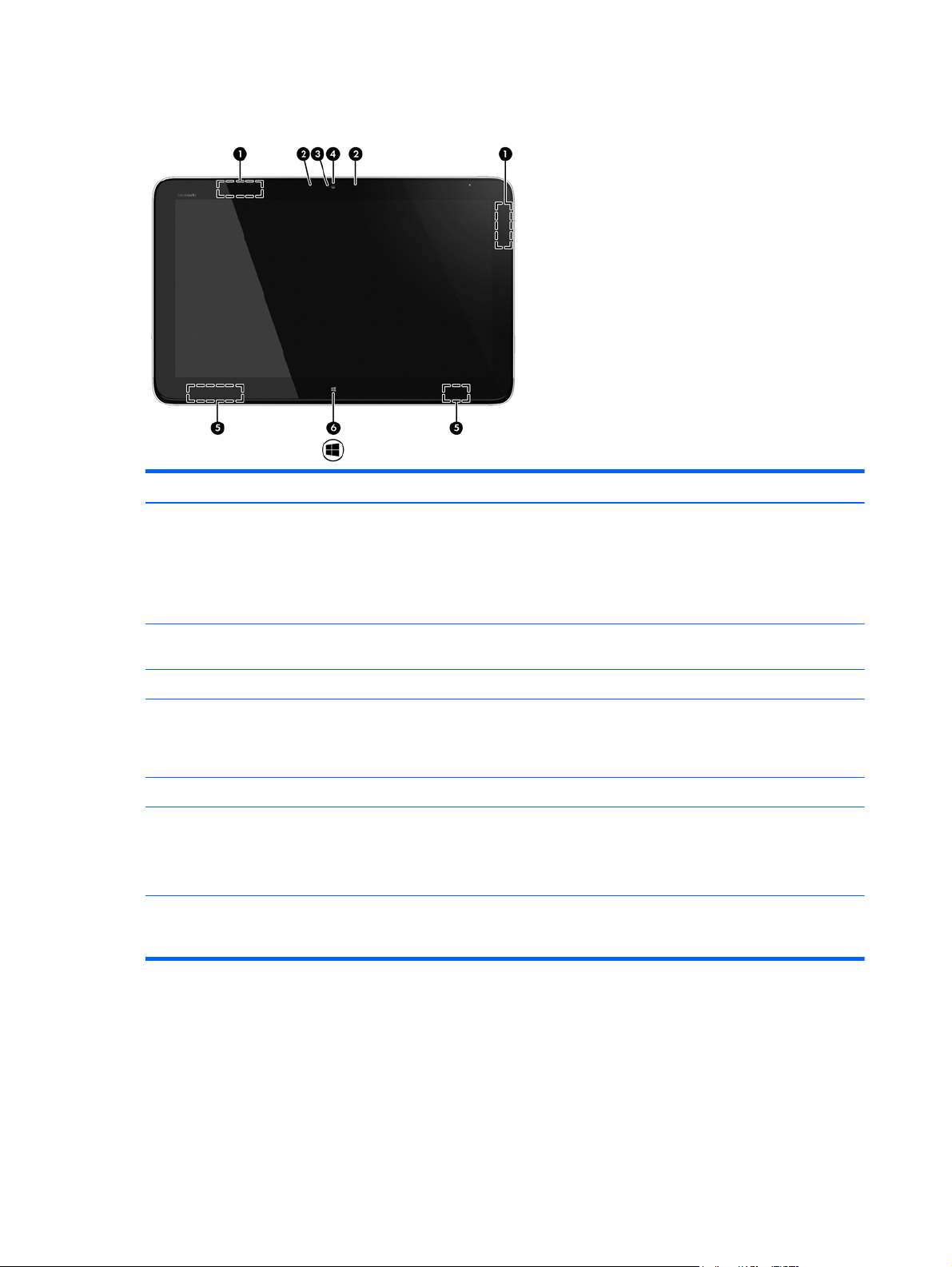
Front
Item Component Description
(1) WLAN antennas (2)* Send and receive wireless signals.
NOTE: To set up a WLAN and connect to the Internet,
you need a broadband modem (either DSL or cable, purchased
separately), high-speed Internet service purchased from an
Internet service provider, and a wireless router
(purchased separately).
(2) Internal microphones (2) Record audio, automatically filtering out the noise around you
and cancelling echoes.
(3) Webcam light On: The webcam is on.
(4) HP TrueVision HD Webcam Records video, captures still photographs, and provides access
(5) Speakers (2) Produce sound.
(6) Windows button Returns you to the Start screen from an open app or the
*The antennas are not visible from the outside of the computer. For optimal transmission, keep the areas immediately
around the antennas free from obstructions. For wireless regulatory notices, see the section of the Regulatory, Safety, and
Environmental Notices that applies to your country or region. These notices are located in Help and Support.
to video conferences and online chat by means of streaming
video. To use the webcam, from the Start screen, type c, and
then select CyberLink YouCam from the list of applications.
Windows desktop.
NOTE: Pressing the Windows button again will return you to
the previous screen.
4 Chapter 2 External component identification
Page 13
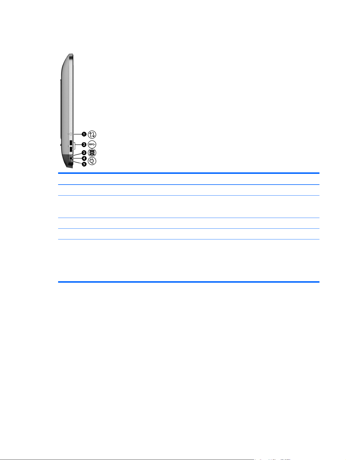
Left side
Item Component Description
(1) Rotate button Rotates the orientation of the display 90 degrees.
(2) USB 3.0 ports (2) Connect optional USB 1.0, USB 2.0, or USB 3.0 devices and
provide enhanced USB power performance for USB 3.0
devices.
(3) Hard drive light Blinking: The hard drive is being used.
(4) Power connector Connects an AC adapter.
(5) AC adapter light ● White: The AC adapter is connected and the battery
is charged.
Amber: The AC adapter is connected and the battery
●
is charging.
● Off: The computer is using DC power.
Left side 5
Page 14
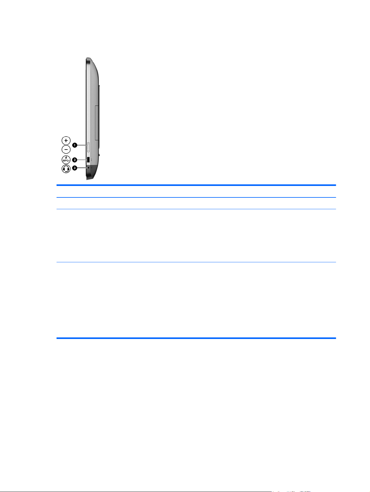
Right side
Item Component Description
(1) Volume control button Controls speaker volume.
(2) USB 3.0 charging (powered) port Connects an optional USB device. USB charging ports allow
you to charge connected USB devices. Standard USB ports will
not charge all USB devices or will charge using a low current.
Some USB devices require power and require you to use a
powered port.
NOTE: USB charging ports can also charge select models of
cell phones and MP3 players, even when the computer is off.
(3) Audio-out (headphone) jack/Audio-in
(microphone) jack
Connects optional powered stereo speakers, headphones,
earbuds, a headset, or a television audio cable. Also connects
an optional headset microphone. This jack does not support
optional microphone-only devices.
WARNING! To reduce the risk of personal injury, adjust the
volume before putting on headphones, earbuds, or a headset.
For additional safety information, refer to the Regulatory, Safety,
and Environmental Notices.
NOTE: When a device is connected to the jack, the computer
speakers are disabled.
6 Chapter 2 External component identification
Page 15
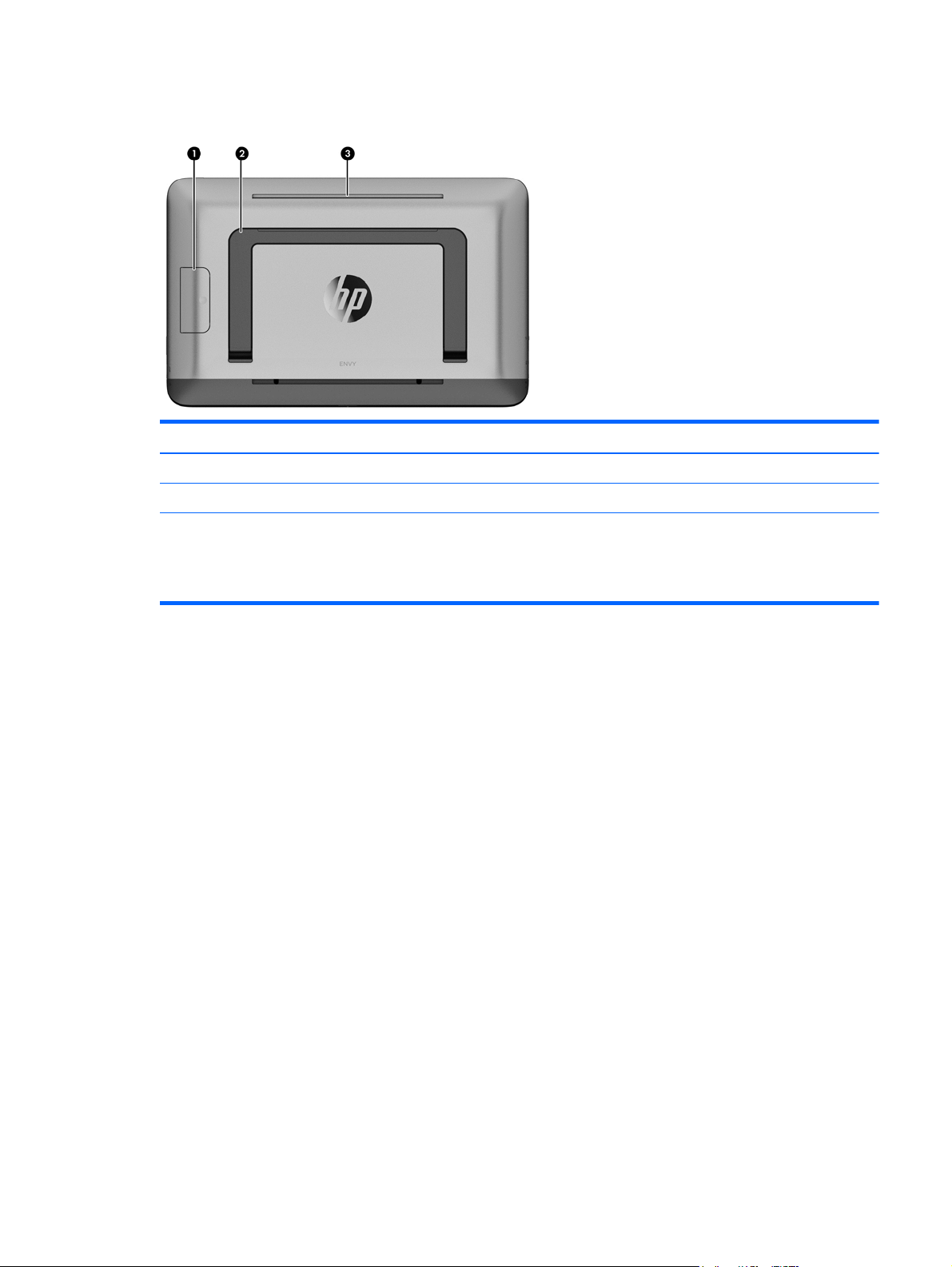
Back
Item Component Description
(1) Display stand release button Releases the display stand.
(2) Display stand Allows the display to be positioned at different angles.
(3) Vent Enables airflow to cool internal components.
NOTE: NOTE: The computer fan starts up automatically to
cool internal components and prevent overheating. It is normal
for the internal fan to cycle on and off during routine operation.
Back 7
Page 16
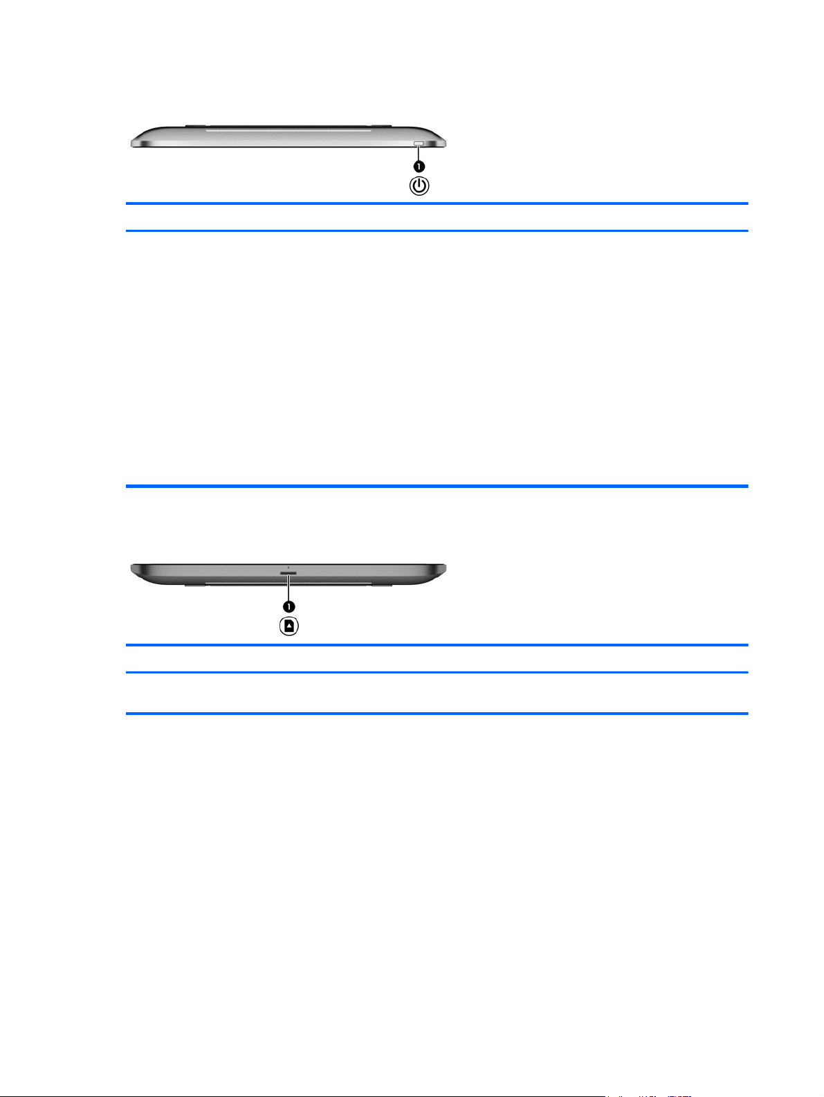
Top
Item Component Description
(1) Power button
Bottom
When the computer is off, press the button to turn on
●
the computer.
When the computer is in the Sleep state, press the button
●
briefly to exit Sleep
When the computer is in Hibernation, press the button
●
down briefly to exit Hibernation.
CAUTION: Pressing and holding down the power button will
cause unsaved information to be lost.
If the computer has stopped responding and Windows®
shutdown procedures aren't working, press and hold the power
button for at least 5 seconds to turn off the computer.
To learn more about your power settings, from the Start screen,
type p. In the search box, type power, select Settings, and
then select Power options.
Item Component Description
(1) Memory card reader Reads data from and writes data to memory cards such as
8 Chapter 2 External component identification
Secure Digital (SD).
Page 17
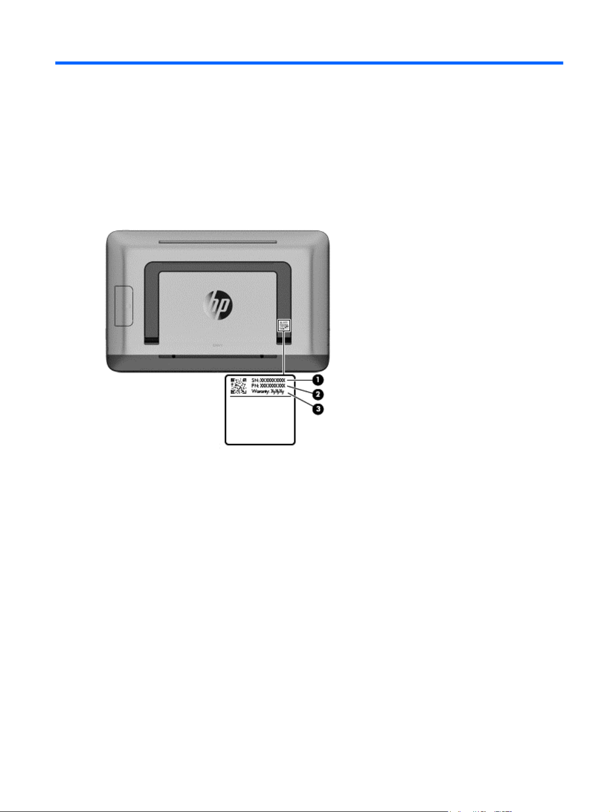
3 Illustrated parts catalog
Locating the serial number, product number, and model number
The serial number and product number of your computer are located on the left edge of the computer.
The model number of your computer is located on the back of your computer. You may need the
information when you travel internationally or when you contact support.
Locating the serial number, product number, and model number 9
Page 18
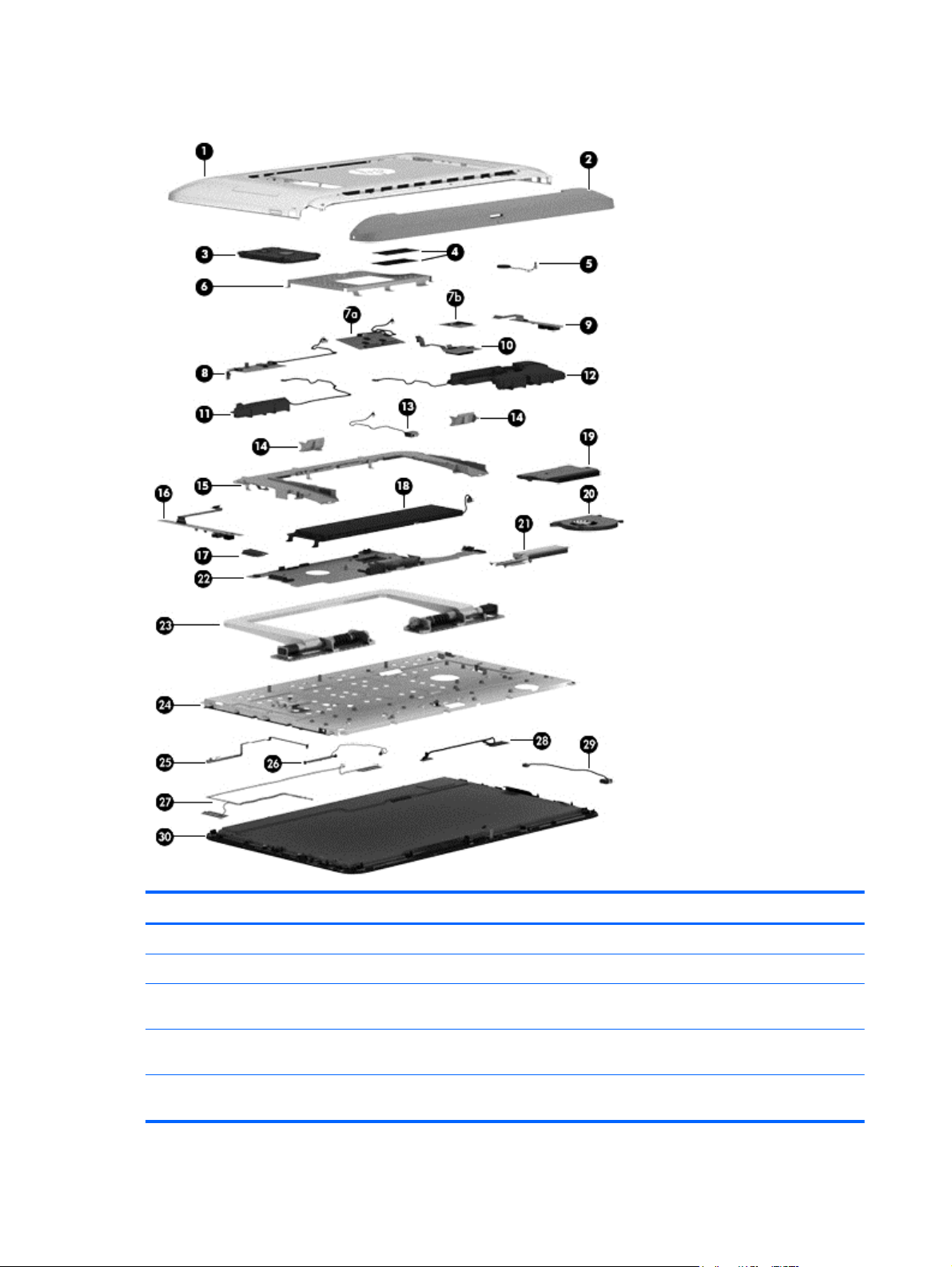
Computer major components
Item Component Spare part number
(1) Rear cover (includes display stand release actuator) 728045-001
(2) Bottom cover (includes 2 captive screws, secured by C-clips) 728046-001
Rubber Kit (not illustrated, includes 2 bottom cover rubber screw covers and media
card reader slot bezel)
(3) 1-TB, 5400-rpm, 9.5-mm hybrid drive with 8-GB NAND cache (does not include
hard drive bracket, hard drive connector cable, or screws)
750-GB, 5400-rpm, 9.5-mm hybrid drive with 8-GB NAND cache (does not include
hard drive bracket, hard drive connector cable, or screws)
10 Chapter 3 Illustrated parts catalog
728073-001
731999-005
732001-001
Page 19

Item Component Spare part number
1-TB 5400-rpm, 9.5mm hard drive 2.5-in (does not include hard drive bracket, hard
750-GB, 5400-rpm (does not include hard drive bracket, hard drive connector cable,
Hard Drive Hardware Kit (not illustrated, includes hard drive bracket, hard drive
(4) Memory modules (2, PC3L, 12800, 1600-MHz):
4-GB 691740-005
2-GB 691739-005
(5) RTC battery (includes cable and double-sided adhesive) 728072-001
(6) Cover bracket 728054-001
Capacitor board, includes:
(7a) X-axis capacitor board
(7b) Y-axis capacitor board (includes double-sided adhesive)
(8) Converter board
drive connector cable, or screws)
or screws)
connector cable, and screws)
NOTE: The capacitor board spare part kit does not include the X-axis capacitor
board cable. The X-axis capacitor board cable is included in the Cable Kit, spare part
number 728048-001. See
NOTE: The converter board spare part kit does not include the converter board
cable or ribbon cable. The converter board cable and ribbon cable are included in the
Cable Kit, spare part number 728048-001. See
Cable Kit information.
Cable Kit on page 12 for more Cable Kit information.
Cable Kit on page 12 for more
676521-005
634250-005
728053-001
728067-001
728066-001
(9) USB board
NOTE: The USB board spare part kit does not include the USB board ribbon cable.
The USB board ribbon cable is included in the Cable Kit, spare part number
728048-001. See
(10) Media card reader board 728068-001
Speaker Kit, includes: 728075-001
(11) Right speaker (includes cable)
(12) Left speaker/subwoofer (includes cable and 3 rubber isolators)
(13) USB connector cable
NOTE: The USB connector cable is included in the Cable Kit, spare part number 728048-001. See
on page 12 for more Cable Kit information.
(14) Display stand covers (2) 728057-001
(15) Display stand recess 728058-001
(16) Audio/USB board
NOTE: The audio/USB board spare part kit does not include the audio/USB board
ribbon cable. The audio/USB board ribbon cable is included in the Cable Kit, spare
part number 728048-001. See
(17) Broadcom BCM4352 802.11ac 2×2 Wi-Fi + BT 4.0 Combo Adapter 724935-005
Cable Kit on page 12 for more Cable Kit information.
Cable Kit on page 12 for more Cable Kit information.
728064-001
728065-001
Cable Kit
Computer major components 11
Page 20

Item Component Spare part number
(18) Battery (3-cell, 50-Wh, 4.52-Ah, Li-ion) 722298-001
(19) Air flow channel 728052-001
(20) Fan (includes cable and mylar shroud) 728050-001
(21) Heat sink (includes replacement thermal material): 728051-001
(22) System board (includes replacement thermal material):
System board equipped with an Intel Core i5-4200U 1.60-GHz processor (turbo up to
2.60-GHz; dual core, ULV, 15 W), a graphics subsystem with UMA memory, and the
Windows 8 Standard operating system
System board equipped with an Intel Core i5-4200U 1.60-GHz processor (turbo up to
2.60-GHz; dual core, ULV, 15 W), a graphics subsystem with UMA memory, and the
Windows 7/Linux operating system
System board equipped with an Intel Core i3-4010U 1.70-GHz processor (dual core,
ULV, 15 W), a graphics subsystem with UMA memory, and the Windows 8 Standard
operating system
System board equipped with an Intel Core i3-4010U 1.70-GHz processor (dual core,
ULV, 15 W), a graphics subsystem with UMA memory, and the Windows 7/Linux
operating system
(23) Display stand 728056-001
(24) Middle frame (includes display assembly pads, display stand release assembly, and
X-axis capacitor board riser)
(25) Power button board (includes ribbon cable) 728063-001
(26) Webcam/microphone module (includes double-sided adhesive and
grounding tape)
(27) Antenna Kit (includes left and right wireless antenna cables and transceivers) 728044-001
(28) Display panel cable 728047-001
737670-501
737670-001
728077-501
728077-001
728055-001
753182-001
728078-001
(29) Power connector cable 728049-001
(30) Display assembly (20.0-inch, AG, HD; includes capacitor board cables, rotation
sensor module and cable, and Windows button board and cable)
Cable Kit
12 Chapter 3 Illustrated parts catalog
728070-001
753183-001
Page 21
Item Component Spare part number
Cable Kit, includes: 728048-001
(1) USB board ribbon cable
(2) X-axis capacitor board cable
(3) Converter board cable
(4) Converter board ribbon cable
(5) Media card reader board ribbon cable
(6) USB connector cable
(7) Webcam/microphone module cable
(8) Audio/USB board ribbon cable
(9) Capacitor board ribbon cable
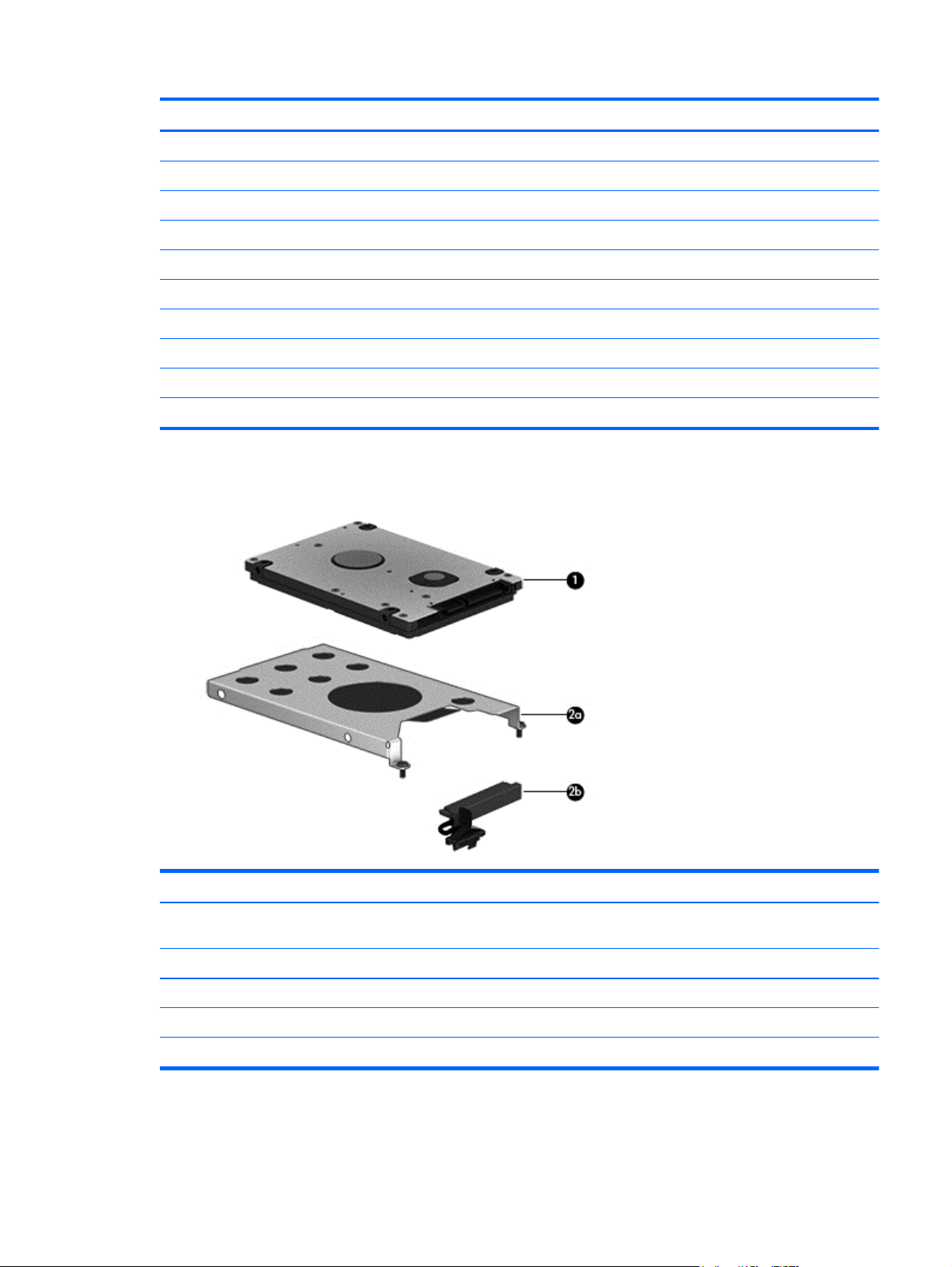
Mass storage device
Item Component Spare part number
(1) 1-TB, 5400-rpm, 9.5-mm hybrid drive with 8-GB NAND cache (2.5-in, SATA, does
not include hard drive bracket, hard drive connector cable, or screws):
Hard Drive Hardware Kit, includes: 728053-001
(2a) Hard drive bracket
(2b) Hard drive connector cable
Hard drive bracket screw (not illustrated)
731999-005
Mass storage device 13
Page 22

Miscellaneous parts
Component Spare part number
AC adapter:
65-W HP Smart AC adapter (non-PFC, EM, 4.5-mm) 714657-001
65-W AC adapter (non-PFC S-3P, 4.5-mm) 710412-001
Power cord (3-pin, black, 1.83-m):
For use in Argentina 490371-D01
For use in Australia 490371-011
For use in Denmark 490371-081
For use in Europe 490371-021
For use in India 490371-D61
For use in Israel 490371-BB1
For use in Italy 490371-061
For use in Japan 490371-291
For use in North America 490371-001
For use in Switzerland 490371-111
For use in the United Kingdom and Singapore 490371-031
RJ45-USB adapter dongle 539614-001
Screw Kit 728074-001
Wireless keyboard:
For use in Belgium 728059-181
For use in Canada 728059-DB1
For use in Denmark, Finland, and Norway 728059-DH1
For use in France 728059-051
For use in Germany 728059-041
For use in India 728059-D61
For use in Israel 728059-BB1
For use in Italy 728059-061
For use in Japan 728059-291
For use in Latin America 728059-161
For use in the Netherlands 728059-L31
For use in Portugal 728059-131
For use in Russia 728059-251
For use in Saudi Arabia 728059-171
For use in Spain 728059-071
14 Chapter 3 Illustrated parts catalog
Page 23

Component Spare part number
For use in Switzerland 728059-111
For use in the United Kingdom and Singapore 728059-031
For use in the United States 728059-001
Wireless mouse 728061-001
Sequential part number listing
Spare part number Description
490371-001 Power cord for use in North America (3-pin, black, 1.83-m)
490371-011 Power cord for use in Australia (3-pin, black, 1.83-m)
490371-021 Power cord for use in Europe (3-pin, black, 1.83-m)
490371-031 Power cord for use in the United Kingdom and Singapore (3-pin, black, 1.83-m)
490371-061 Power cord for use in Italy (3-pin, black, 1.83-m)
490371-081 Power cord for use in Denmark (3-pin, black, 1.83-m)
490371-111 Power cord for use in Switzerland (3-pin, black, 1.83-m)
490371-291 Power cord for use in Japan (3-pin, black, 1.83-m)
490371-BB1 Power cord for use in Israel (3-pin, black, 1.83-m)
490371-D01 Power cord for use in Argentina (3-pin, black, 1.83-m)
490371-D61 Power cord for use in India (3-pin, black, 1.83-m)
539614-001 RJ45-USB adapter dongle
634250-005 750-GB, 5400-rpm, 9.5-mm hybrid drive (does not include hard drive bracket, hard drive
659940-001 External DVD±RW Double-Layer with SuperMulti Drive
676521-005 750-GB, 5400-rpm, 9.5-mm hybrid drive with 8-GB NAND cache (2.5-in, SATA, does not include
691739-005 2-GB memory module (PC3L, 12800, 1600-MHz)
691740-005 4-GB memory module (PC3L, 12800, 1600-MHz)
710412-001 65-W AC adapter (non-PFC S-3P, 4.5-mm)
714657-001 65-W HP Smart AC adapter (non-PFC, EM, 4.5-mm)
722298-001 3-cell, 50-Wh, 4.52-Ah, Li-ion battery
724935-005 Broadcom BCM4352 802.11ac 2×2 Wi-Fi + BT 4.0 Combo Adapter
728044-001 Antenna Kit (includes left and right wireless antenna cables and transceivers)
connector cable, or screws)
hard drive bracket, hard drive connector cable, or screws):
728045-001 Rear cover (includes display stand release actuator)
728046-001 Bottom cover (includes 2 captive screws, secured by C-clips)
728047-001 Display panel cable
Sequential part number listing 15
Page 24

Spare part number Description
728048-001 Cable Kit
See
Cable Kit on page 12 for more Cable Kit information.
728049-001 Power connector cable
728050-001 Fan (includes cable and mylar shroud)
728051-001 Heat sink (includes replacement thermal material)
728052-001 Air flow channel
728053-001 Hard Drive Hardware Kit (includes hard drive bracket, hard drive connector cable, and screws)
NOTE: See
728054-001 Cover bracket
Mass storage device on page 13 for more Hard Drive Hardware Kit information.
728055-001 Middle frame (includes display assembly pads, display stand release assembly, and X-axis
728056-001 Display stand
728057-001 Display stand covers (includes left and right display stand covers)
728058-001 Display stand recess
728059-001 Wireless keyboard for use in the United States
728059-031 Wireless keyboard for use in the United Kingdom and Singapore
728059-041 Wireless keyboard for use in France
728059-051 Wireless keyboard for use in Germany
728059-061 Wireless keyboard for use in Italy
728059-071 Wireless keyboard for use in Spain
728059-111 Wireless keyboard for use in Switzerland
728059-131 Wireless keyboard for use in Portugal
728059-161 Wireless keyboard for use in Latin America
728059-171 Wireless keyboard for use in Saudi Arabia
728059-181 Wireless keyboard for use in Belgium
728059-251 Wireless keyboard for use in Russia
capacitor board riser)
728059-291 Wireless keyboard for use in Japan
728059-BB1 Wireless keyboard for use in Israel
728059-D61 Wireless keyboard for use in India
728059-DB1 Wireless keyboard for use in Canada
728059-DH1 Wireless keyboard for use in Denmark, Finland, and Norway
728059-L31 Wireless keyboard for use in the Netherlands
728061-001 Wireless mouse
728063-001 Power button board (includes ribbon cable)
728064-001 USB board
16 Chapter 3 Illustrated parts catalog
Page 25

Spare part number Description
728065-001 Audio/USB board
728066-001 Converter board
728067-001 Capacitor board (include X-axis capacitor board, Y-axis capacitor board, and double-
728068-001 Media card reader board
728070-001 20.0-inch, AG, HD display assembly (includes capacitor board cables, rotation sensor module and
728072-001 RTC battery (includes cable and double-sided adhesive)
728073-001 Rubber Kit (includes 2 bottom cover rubber screw covers)
728074-001 Screw Kit
728075-001 Speaker Kit (includes left speaker/subwoofer and right speaker, cables, and 3 rubber isolators)
728077-001 System board equipped with an Intel i3-4010U 1.70-GHz processor (dual core, ULV, 15 W), a
728077-501 System board equipped with an Intel i3-4010U 1.70-GHz processor (dual core, ULV, 15 W), a
728078-001 Webcam/microphone module (includes double-sided adhesive and grounding tape)
731999-005 1-TB, 5400-rpm, 9.5-mm hybrid drive with 8-GB NAND cache (2.5-in, SATA, does not include
732001-001 750-GB, 5400-rpm, 9.5-mm hybrid drive with 8-GB NAND cache (2.5-in, SATA, does not include
sided adhesive)
cable, and Windows button board and cable)
graphics subsystem with UMA memory, and the Windows 7/Linux operating system (includes
replacement thermal material)
graphics subsystem with UMA memory, and the Windows 8 Standard operating system (includes
replacement thermal material)
hard drive bracket, hard drive connector cable, or screws)
hard drive bracket, hard drive connector cable, or screws)
737670-001 System board equipped with an Intel i5-4200U 1.60-GHz processor (turbo up to 2.60-GHz; dual
737670-501 System board equipped with an Intel i5-4200U 1.60-GHz processor (turbo up to 2.60-GHz; dual
753182-001 Middle frame (includes display assembly pads, display stand release assembly, and X-axis
753183-001 20.0-inch, AG, HD display assembly (includes capacitor board cables, rotation sensor module and
core, ULV, 15 W), a graphics subsystem with UMA memory, and the Windows 7/Linux
operating system (includes replacement thermal material)
core, ULV, 15 W), a graphics subsystem with UMA memory, and the Windows 8 Standard
operating system (includes replacement thermal material)
capacitor board riser)
cable, and Windows button board and cable)
Sequential part number listing 17
Page 26

4 Removal and replacement procedures
Preliminary replacement requirements
Tools required
You will need the following tools to complete the removal and replacement procedures:
● Flat-bladed screw driver
Magnetic screw driver
●
Phillips P1 screw driver
●
● Phillips P0 screw driver
● Phillips P00 screw driver
Service considerations
The following sections include some of the considerations that you must keep in mind during
disassembly and assembly procedures.
NOTE: As you remove each subassembly from the computer, place the subassembly (and all
accompanying screws) away from the work area to prevent damage.
Plastic parts
CAUTION: Using excessive force during disassembly and reassembly can damage plastic parts.
Use care when handling the plastic parts. Apply pressure only at the points designated in the
maintenance instructions.
18 Chapter 4 Removal and replacement procedures
Page 27

Cables and connectors
CAUTION: When servicing the computer, be sure that cables are placed in their proper locations
during the reassembly process. Improper cable placement can damage the computer.
Cables must be handled with extreme care to avoid damage. Apply only the tension required to
unseat or seat the cables during removal and insertion. Handle cables by the connector whenever
possible. In all cases, avoid bending, twisting, or tearing cables. Be sure that cables are routed in
such a way that they cannot be caught or snagged by parts being removed or replaced. Handle flex
cables with extreme care; these cables tear easily.
Drive handling
CAUTION: Drives are fragile components that must be handled with care. To prevent damage to
the computer, damage to a drive, or loss of information, observe these precautions:
Before removing or inserting a hard drive, shut down the computer. If you are unsure whether the
computer is off or in Hibernation, turn the computer on, and then shut it down through the
operating system.
Before handling a drive, be sure that you are discharged of static electricity. While handling a drive,
avoid touching the connector.
Before removing a diskette drive or optical drive, be sure that a diskette or disc is not in the drive and
be sure that the optical drive tray is closed.
Handle drives on surfaces covered with at least one inch of shock-proof foam.
Avoid dropping drives from any height onto any surface.
After removing a hard drive, an optical drive, or a diskette drive, place it in a static-proof bag.
Avoid exposing an internal hard drive to products that have magnetic fields, such as monitors
or speakers.
Avoid exposing a drive to temperature extremes or liquids.
If a drive must be mailed, place the drive in a bubble pack mailer or other suitable form of protective
packaging and label the package “FRAGILE.”
Preliminary replacement requirements 19
Page 28

Grounding guidelines
Electrostatic discharge damage
Electronic components are sensitive to electrostatic discharge (ESD). Circuitry design and structure
determine the degree of sensitivity. Networks built into many integrated circuits provide some
protection, but in many cases, ESD contains enough power to alter device parameters or melt
silicon junctions.
A discharge of static electricity from a finger or other conductor can destroy static-sensitive devices or
microcircuitry. Even if the spark is neither felt nor heard, damage may have occurred.
An electronic device exposed to ESD may not be affected at all and can work perfectly throughout a
normal cycle. Or the device may function normally for a while, then degrade in the internal layers,
reducing its life expectancy.
CAUTION: To prevent damage to the computer when you are removing or installing internal
components, observe these precautions:
Keep components in their electrostatic-safe containers until you are ready to install them.
Before touching an electronic component, discharge static electricity by using the guidelines
described in this section.
Avoid touching pins, leads, and circuitry. Handle electronic components as little as possible.
If you remove a component, place it in an electrostatic-safe container.
The following table shows how humidity affects the electrostatic voltage levels generated by
different activities.
CAUTION: A product can be degraded by as little as 700 V.
Typical electrostatic voltage levels
Relative humidity
Event 10% 40% 55%
Walking across carpet 35,000 V 15,000 V 7,500 V
Walking across vinyl floor 12,000 V 5,000 V 3,000 V
Motions of bench worker 6,000 V 800 V 400 V
Removing DIPS from plastic tube 2,000 V 700 V 400 V
Removing DIPS from vinyl tray 11,500 V 4,000 V 2,000 V
Removing DIPS from Styrofoam 14,500 V 5,000 V 3,500 V
Removing bubble pack from PCB 26,500 V 20,000 V 7,000 V
Packing PCBs in foam-lined box 21,000 V 11,000 V 5,000 V
20 Chapter 4 Removal and replacement procedures
Page 29

Packaging and transporting guidelines
Follow these grounding guidelines when packaging and transporting equipment:
To avoid hand contact, transport products in static-safe tubes, bags, or boxes.
●
Protect ESD-sensitive parts and assemblies with conductive or approved containers or
●
packaging.
Keep ESD-sensitive parts in their containers until the parts arrive at static-free workstations.
●
Place items on a grounded surface before removing items from their containers.
●
Always be properly grounded when touching a component or assembly.
●
● Store reusable ESD-sensitive parts from assemblies in protective packaging or
nonconductive foam.
Use transporters and conveyors made of antistatic belts and roller bushings. Be sure that
●
mechanized equipment used for moving materials is wired to ground and that proper materials
are selected to avoid static charging. When grounding is not possible, use an ionizer to dissipate
electric charges.
Workstation guidelines
Follow these grounding workstation guidelines:
● Cover the workstation with approved static-shielding material.
● Use a wrist strap connected to a properly grounded work surface and use properly grounded
tools and equipment.
Use conductive field service tools, such as cutters, screw drivers, and vacuums.
●
● When fixtures must directly contact dissipative surfaces, use fixtures made only of static-
safe materials.
Keep the work area free of nonconductive materials, such as ordinary plastic assembly aids
●
and Styrofoam.
Handle ESD-sensitive components, parts, and assemblies by the case or PCM laminate. Handle
●
these items only at static-free workstations.
● Avoid contact with pins, leads, or circuitry.
● Turn off power and input signals before inserting or removing connectors or test equipment.
Preliminary replacement requirements 21
Page 30

Equipment guidelines
Grounding equipment must include either a wrist strap or a foot strap at a grounded workstation.
When seated, wear a wrist strap connected to a grounded system. Wrist straps are flexible
●
straps with a minimum of one megohm ±10% resistance in the ground cords. To provide proper
ground, wear a strap snugly against the skin at all times. On grounded mats with banana-plug
connectors, use alligator clips to connect a wrist strap.
When standing, use foot straps and a grounded floor mat. Foot straps (heel, toe, or boot straps)
●
can be used at standing workstations and are compatible with most types of shoes or boots. On
conductive floors or dissipative floor mats, use foot straps on both feet with a minimum of one
megohm resistance between the operator and ground. To be effective, the conductive must be
worn in contact with the skin.
The following grounding equipment is recommended to prevent electrostatic damage:
Antistatic tape
●
Antistatic smocks, aprons, and sleeve protectors
●
● Conductive bins and other assembly or soldering aids
Nonconductive foam
●
Conductive tabletop workstations with ground cords of one megohm resistance
●
● Static-dissipative tables or floor mats with hard ties to the ground
● Field service kits
Static awareness labels
●
Material-handling packages
●
● Nonconductive plastic bags, tubes, or boxes
Metal tote boxes
●
Electrostatic voltage levels and protective materials
●
The following table lists the shielding protection provided by antistatic bags and floor mats.
Material Use Voltage protection level
Antistatic plastics Bags 1,500 V
Carbon-loaded plastic Floor mats 7,500 V
Metallized laminate Floor mats 5,000 V
Component replacement procedures
CAUTION: Components described in this chapter should only be accessed by an authorized
service provider. Accessing these parts can damage the computer or void the warranty.
This chapter provides removal and replacement procedures for Authorized Service Provider only
parts.
There are as many as 82 screws that must be removed, replaced, and/or loosened when servicing
the computer. Make special note of each screw size and location during removal and replacement.
22 Chapter 4 Removal and replacement procedures
Page 31

Bottom cover
Description Spare part number
Bottom cover (includes 2 captive screws, secured by C-clips) 728046-001
Before disassembling the computer, follow these steps:
1. Turn off the computer. If you are unsure whether the computer is off or in Hibernation, turn the
computer on, and then shut it down through the operating system.
2. Disconnect the power from the computer by unplugging the power cord from the computer.
3. Disconnect all external devices from the computer.
Remove the bottom cover:
CAUTION: Before positioning the computer with the display screen facing down, make sure the
work surface is clear of tools, screws, and any other foreign objects. Failure to follow this caution can
result in damage to the display screen.
1. Position the computer with the display screen facing down and the bottom edge toward you.
2. Press in on the media card reader slot bezel (1) to release the bezel from the slot, and then
press in on the bezel (2) a second time to remove the bezel from the slot.
The media card reader slot bezel is included in the Rubber Kit, spare part number 728073-001.
3. Remove the two rubber screw covers (1).
The rubber screw covers are included in the Rubber Kit, spare part number 728073-001.
4. Loosen the two Phillips PM2.5×5.0 captive screws (2) that secure the bottom cover to
the computer.
Component replacement procedures 23
Page 32

5. Lift up on the top edge of the bottom cover (3), and then swing it up and forward until it detaches
from the computer.
6. Remove the bottom cover.
After the bottom cover is removed, the internal USB connector is accessible. If it is necessary to
remove or replace the wireless receiver dongle, follow these steps:
1. Disconnect the dongle (1) from the internal USB connector.
2. Remove the dongle (2) from the tablet.
3. Insert the replacement dongle (1) into the cavity next to the internal USB connector.
24 Chapter 4 Removal and replacement procedures
Page 33

4. Connect the dongle (2) to the internal USB connector.
Reverse this procedure to install the bottom cover.
Component replacement procedures 25
Page 34

Rear cover
Description Spare part number
Rear cover (includes display stand release actuator) 728045-001
Before removing the rear cover, follow these steps:
1. Turn off the computer. If you are unsure whether the computer is off or in Hibernation, turn the
2. Disconnect the power from the computer by unplugging the power cord from the computer.
3. Disconnect all external devices from the computer.
computer on, and then shut it down through the operating system.
4. Remove the bottom cover (see
Bottom cover on page 23).
Remove the rear cover:
1. Remove the five Phillips PM3.0×6.5 screws (1) that secure the rear cover to the computer.
2. Lift up on the bottom edge of the rear cover (2), and then swing it up and back until it detaches
from the computer.
3. Remove the rear cover (3).
Reverse this procedure to install the rear cover.
26 Chapter 4 Removal and replacement procedures
Page 35

Hard drive
NOTE: The hard drive spare part kit does not include the hard drive bracket, hard drive connector
cable, or screws. These components are available in the Hard Drive Hardware Kit, spare part number
728053-001.
Description Spare part number
1-TB, 5400-rpm, 9.5-mm hybrid drive with 8-GB NAND cache 731999-005
750-GB, 5400-rpm, 9.5-mm hybrid drive with 8-GB NAND cache 732001-001
1-TB 5400-rpm, 9.5-mm hard drive 676521-005
750-GB, 5400-rpm 9.5-mm 634250-005
Before removing the hard drive, follow these steps:
1. Turn off the computer. If you are unsure whether the computer is off or in Hibernation, turn the
2. Disconnect the power from the computer by unplugging the power cord from the computer.
3. Disconnect all external devices from the computer.
computer on, and then shut it down through the operating system.
4. Remove the bottom cover (see
5. Remove the rear cover (see
Bottom cover on page 23).
Rear cover on page 26).
Remove the hard drive:
1. Disconnect the battery cable from the system board.
2. Disconnect the hard drive connector cable (1) from the system board.
3. Loosen the two Phillips PM2.5×6.5 screws (2) that secure the hard drive to the computer.
Component replacement procedures 27
Page 36

4. Lift up on the hard drive tab (3) to remove the hard drive (4) from the hard drive bay.
5. If it is necessary to disassemble the hard drive, perform the following steps:
a. Position the hard drive with the connector toward you.
b. Disconnect the hard drive connector cable (1) from the hard drive.
c. Remove the four Phillips PM3.0×3.5 screws (2) that secure the hard drive bracket to the
hard drive.
d. Remove the hard drive bracket (3) from the hard drive.
The hard drive bracket, hard drive connector cable, and screws are available in the Hard
Drive Hardware Kit, spare part number 728053-001.
Reverse this procedure to reassemble and install the hard drive.
28 Chapter 4 Removal and replacement procedures
Page 37

Memory module
Description Spare part number
4-GB (PC3L, 12800, 1600-MHz) 691740-005
2-GB (PC3L, 12800, 1600-MHz) 691739-005
Update BIOS before adding memory modules
Before adding new memory, make sure you update the computer to the latest BIOS.
CAUTION: Failure to update the computer to the latest BIOS prior to installing new memory may
result in various system problems.
To update BIOS:
1. Navigate to
www.hp.com.
2. Click Support & Drivers > click Drivers & Software.
3. In the Enter a product name/number box, type the computer model information, and then click
Search.
4. Click the link for the computer model.
5. Select the operating system, and then click Next.
6. Under Step 2: Select a Download, click the BIOS link.
7. Click the link for the most recent BIOS.
8. Click the Download button, and then follow the on-screen instructions.
Before removing a memory module, follow these steps:
1. Turn off the computer. If you are unsure whether the computer is off or in Hibernation, turn the
computer on, and then shut it down through the operating system.
2. Disconnect the power from the computer by unplugging the power cord from the computer.
3. Disconnect all external devices from the computer.
4. Remove the bottom cover (see
5. Remove the rear cover (see
Bottom cover on page 23).
Rear cover on page 26).
6. Disconnect the battery cable (see
Hard drive on page 27).
Remove the memory module:
1. Spread the retaining tabs (1) on each side of the memory module slot to release the memory
module. (The memory module tilts up.)
Component replacement procedures 29
Page 38

2. Remove the memory module (2) by pulling the module away from the slot at an angle.
Reverse this procedure to install a memory module.
Y-axis capacitor board
Description Spare part number
Y-axis capacitor board (includes double-sided adhesive) 728067-001
Before removing the Y-axis capacitor board, follow these steps:
1. Turn off the computer. If you are unsure whether the computer is off or in Hibernation, turn the
computer on, and then shut it down through the operating system.
2. Disconnect the power from the computer by unplugging the power cord from the computer.
3. Disconnect all external devices from the computer.
4. Remove the bottom cover (see
5. Remove the rear cover (see
6. Disconnect the battery cable (see
Remove the Y-axis capacitor board:
1. Release the ZIF connector (1) to which the capacitor board ribbon cable is attached, and then
disconnect the capacitor board ribbon cable from the Y-axis capacitor board.
2. Release the ZIF connector (2) to which the display panel ribbon cable is attached, and then
disconnect the display panel ribbon cable from the Y-axis capacitor board.
Bottom cover on page 23).
Rear cover on page 26).
Hard drive on page 27).
30 Chapter 4 Removal and replacement procedures
Page 39

3. Detach the Y-axis capacitor board (3) from the middle frame. (The Y-axis capacitor board is
attached to the middle frame with double-sided adhesive.)
4. Remove the Y-axis capacitor board.
Reverse this procedure to install the Y-axis capacitor board.
RTC battery
Description Spare part number
RTC battery (includes cable and double-sided adhesive) 728072-001
Before removing the RTC battery, follow these steps:
1. Turn off the computer. If you are unsure whether the computer is off or in Hibernation, turn the
computer on, and then shut it down through the operating system.
2. Disconnect the power from the computer by unplugging the power cord from the computer.
3. Disconnect all external devices from the computer.
4. Remove the bottom cover (see
5. Remove the rear cover (see
6. Disconnect the battery cable (see
7. Remove the Y-axis capacitor board (see
Remove the RTC battery:
1. Disconnect the RTC battery cable (1) from the system board.
Bottom cover on page 23).
Rear cover on page 26).
Hard drive on page 27).
Y-axis capacitor board on page 30).
Component replacement procedures 31
Page 40

2. Detach the RTC battery (2) from the middle frame. (The RTC battery is attached to the middle
frame with double-sided adhesive.)
3. Remove the RTC battery.
Reverse this procedure to install the RTC battery.
USB board
NOTE: The USB board spare part kit does not include the USB board ribbon cable. The USB board
ribbon cable is included in the Cable Kit, spare part number 728048-001. See
for more Cable Kit information.
Description Spare part number
USB board 728064-001
Before removing the USB board, follow these steps:
1. Turn off the computer. If you are unsure whether the computer is off or in Hibernation, turn the
2. Disconnect the power from the computer by unplugging the power cord from the computer.
3. Disconnect all external devices from the computer.
4. Remove the bottom cover (see
5. Remove the rear cover (see
6. Disconnect the battery cable (see
Cable Kit on page 12
computer on, and then shut it down through the operating system.
Bottom cover on page 23).
Rear cover on page 26).
Hard drive on page 27).
32 Chapter 4 Removal and replacement procedures
Page 41

Remove the USB board:
1. Release the ZIF connector (1) to which the USB board ribbon cable is attached, and then
disconnect the USB board ribbon cable from the system board.
2. Detach the USB board ribbon cable (2) from the middle frame. (The USB board ribbon cable is
attached to the middle frame with double-sided adhesive.)
3. Remove the three Phillips PM3.0×6.5 screws (3) that secure the USB board to the
display assembly.
4. Remove the USB board (4) and cable.
Reverse this procedure to install the USB board.
X-axis capacitor board
NOTE: The X-axis capacitor board spare part kit does not include the X-axis capacitor board cable.
The X-axis capacitor board cable is included in the Cable Kit, spare part number 728048-001. See
Cable Kit on page 12 for more Cable Kit information.
Description Spare part number
X-axis capacitor board 728067-001
Before removing the X-axis capacitor board, follow these steps:
1. Turn off the computer. If you are unsure whether the computer is off or in Hibernation, turn the
computer on, and then shut it down through the operating system.
2. Disconnect the power from the computer by unplugging the power cord from the computer.
3. Disconnect all external devices from the computer.
4. Remove the bottom cover (see
Bottom cover on page 23).
Component replacement procedures 33
Page 42

5. Remove the rear cover (see Rear cover on page 26).
6. Disconnect the battery cable (see
Hard drive on page 27).
Remove the X-axis capacitor board:
1. Remove the Phillips PM3.0×4.5 screw (1) and the two Phillips PM3.0×6.5 screws (2) that secure
the cover bracket to the computer.
2. Remove the cover bracket (3).
The cover bracket is available using spare part number 728054-001.
3. Release the two ZIF connectors (1) to which the two display panel ribbon cables are attached,
and then disconnect the two display panel ribbon cables from the X-axis capacitor board.
4. Release the ZIF connector (2) to which the capacitor board ribbon cable is attached, and then
disconnect the capacitor board ribbon cable from the X-axis capacitor board.
5. Disconnect the X-axis capacitor board cable (3) from the system board.
6. Release the X-axis capacitor board cable from the clips (4) built into the middle frame.
7. Remove the two Phillips PM2.5×3.0 screws (5) that secure the X-axis capacitor board to the
middle frame.
34 Chapter 4 Removal and replacement procedures
Page 43

8. Remove the X-axis capacitor board (6) and cable.
Reverse this procedure to install the X-axis capacitor board.
Converter board
NOTE: The converter board spare part kit does not include the converter board cable or converter
board ribbon cable. The converter board cable and converter board ribbon cable are included in the
Cable Kit, spare part number 728048-001. See
Description Spare part number
Converter board 728067-001
Cable Kit on page 12 for more Cable Kit information.
Before removing the converter board, follow these steps:
1. Turn off the computer. If you are unsure whether the computer is off or in Hibernation, turn the
computer on, and then shut it down through the operating system.
2. Disconnect the power from the computer by unplugging the power cord from the computer.
3. Disconnect all external devices from the computer.
4. Remove the bottom cover (see
5. Remove the rear cover (see
6. Disconnect the battery cable (see
7. Remove the cover bracket (see
Bottom cover on page 23).
Rear cover on page 26).
Hard drive on page 27).
X-axis capacitor board on page 33).
Remove the converter board:
1. Disconnect the converter board ribbon cable (1) from the low insertion force (LIF) connector on
the display assembly.
2. Disconnect the converter board cable (2) from the system board.
3. Release the converter board cable from the clips (3) built into the middle frame.
Component replacement procedures 35
Page 44

4. Release the converter board cable from the clips (4) built into the X-axis capacitor board riser.
5. Remove the two Phillips PM3.0×4.5 screws (5) that secure the converter board to the
middle frame.
6. Remove the converter board (6) and cables.
Reverse this procedure to install the converter board.
36 Chapter 4 Removal and replacement procedures
Page 45

Media card reader board
NOTE: The media card reader board spare part kit does not include the media card reader board
ribbon cable. The media card reader board ribbon cable is included in the Cable Kit, spare part
number 728048-001. See
Description Spare part number
Media card reader board 728068-001
Before removing the media card reader board, follow these steps:
1. Turn off the computer. If you are unsure whether the computer is off or in Hibernation, turn the
computer on, and then shut it down through the operating system.
2. Disconnect the power from the computer by unplugging the power cord from the computer.
3. Disconnect all external devices from the computer.
Cable Kit on page 12 for more Cable Kit information.
4. Remove the bottom cover (see
5. Remove the rear cover (see
6. Disconnect the battery cable (see
7. Remove the cover bracket (see
Bottom cover on page 23).
Rear cover on page 26).
Hard drive on page 27).
X-axis capacitor board on page 33).
Remove the media card reader board:
1. Release the ZIF connector (1) to which the media card reader board ribbon cable is attached,
and then disconnect the media card reader board ribbon cable from the system board.
2. Release the media card reader board ribbon cable from the clips (2) built into the middle frame.
3. Release the ZIF connector (3) to which the Windows button ribbon cable is attached, and then
disconnect the Windows button ribbon cable from the media card reader board.
4. Remove the two Phillips PM3.0×4.5 screws (4) that secure the media card reader board to the
middle frame and display assembly.
Component replacement procedures 37
Page 46

5. Remove the media card reader board (5) and cable.
Reverse this procedure to install the media card reader board.
USB connector cable
NOTE: The USB connector cable is included in the Cable Kit, spare part number 728048-001. See
Cable Kit on page 12 for more Cable Kit information.
Before removing the USB connector cable, follow these steps:
1. Turn off the computer. If you are unsure whether the computer is off or in Hibernation, turn the
computer on, and then shut it down through the operating system.
2. Disconnect the power from the computer by unplugging the power cord from the computer.
3. Disconnect all external devices from the computer.
4. Remove the bottom cover (see
5. Remove the rear cover (see
6. Disconnect the battery cable (see
7. Remove the cover bracket (see
8. Remove the X-axis capacitor board (see
9. Remove the converter board (see
10. Remove the media card reader board (see
Remove the USB connector cable:
1. Disconnect the USB connector cable (1) from the system board.
Bottom cover on page 23).
Rear cover on page 26).
Hard drive on page 27).
X-axis capacitor board on page 33).
X-axis capacitor board on page 33).
Converter board on page 35).
Media card reader board on page 37).
2. Release the USB connector cable (2) from the clips built into the middle frame.
3. Remove the Phillips PM2.5×3.0 screw (3) that secures the USB connector cable to the
display assembly.
38 Chapter 4 Removal and replacement procedures
Page 47

4. Remove the USB connector cable (4).
Reverse this procedure to install the USB connector cable.
Speakers
Description Spare part number
Speaker Kit (includes right speaker, left speaker/subwoofer, cables, and 3 rubber isolators) 728075-001
Before removing the speakers, follow these steps:
1. Turn off the computer. If you are unsure whether the computer is off or in Hibernation, turn the
computer on, and then shut it down through the operating system.
2. Disconnect the power from the computer by unplugging the power cord from the computer.
3. Disconnect all external devices from the computer.
4. Remove the bottom cover (see
5. Remove the rear cover (see
6. Disconnect the battery cable (see
7. Remove the X-axis capacitor board (see
8. Remove the converter board (see
9. Remove the media card reader board (see
Bottom cover on page 23).
Rear cover on page 26).
Hard drive on page 27).
X-axis capacitor board on page 33).
Converter board on page 35).
Media card reader board on page 37).
Remove the speakers:
1. Disconnect the right speaker cable (1) from the system board.
2. Release the right speaker cable from the clips (2) built into the middle frame.
3. Remove the Phillips PM3.0×6.5 screw (3) that secures the right speaker to the middle frame.
Component replacement procedures 39
Page 48

4. Remove the right speaker (4) and cable.
5. Release the power connector cable from the clip (1) built into the left speaker/subwoofer.
6. Disconnect the left speaker/subwoofer cable (2) from the system board.
7. Release the left speaker/subwoofer cable from the clips (3) built into the middle frame.
8. Remove the three Phillips PM3.0×6.5 screws (4) that secure the left speaker/subwoofer to the
middle frame.
NOTE: The left speaker/subwoofer includes three rubber isolators that are installed in the
screw holes (5). These isolators are crucial to the performance of the subwoofer.
9. Remove the left speaker/subwoofer (6) and cable.
Reverse this procedure to install the speakers.
40 Chapter 4 Removal and replacement procedures
Page 49

Display stand recess
Description Spare part number
Display stand recess 728058-001
Before removing the display stand recess, follow these steps:
1. Turn off the computer. If you are unsure whether the computer is off or in Hibernation, turn the
computer on, and then shut it down through the operating system.
2. Disconnect the power from the computer by unplugging the power cord from the computer.
3. Disconnect all external devices from the computer.
4. Remove the bottom cover (see
5. Remove the rear cover (see
6. Disconnect the battery cable (see
7. Remove the hard drive (see
8. Remove the cover bracket (see
Bottom cover on page 23).
Rear cover on page 26).
Hard drive on page 27).
Hard drive on page 27).
X-axis capacitor board on page 33).
Remove the display stand recess:
1. Remove the two Phillips PM3.0×4.5 screws (1) that secure the display stand cover to the middle
frame.
2. Remove the left (2) and right display stand covers (3).
The display stand covers are available using spare part number 728057-001.
Component replacement procedures 41
Page 50

3. Press down on the display stand release actuator (1). (The display stand (2) releases to the
open position.)
4. Disconnect the display panel cable (1) from the system board.
5. Release the display panel cable from the clips (2) built into the display stand recess.
6. Remove the eleven Phillips PM3.0×6.5 screws (3) that secure the display stand recess to the
middle frame.
7. Remove the display stand recess (4).
Reverse this procedure to install the display stand covers and display stand recess.
Power button board
Description Spare part number
Power button board (includes ribbon cable) 728063-001
42 Chapter 4 Removal and replacement procedures
Page 51

Before removing the power button board, follow these steps:
1. Turn off the computer. If you are unsure whether the computer is off or in Hibernation, turn the
computer on, and then shut it down through the operating system.
2. Disconnect the power from the computer by unplugging the power cord from the computer.
3. Disconnect all external devices from the computer.
4. Remove the bottom cover (see
5. Remove the rear cover (see
6. Disconnect the battery cable (see
7. Remove the hard drive (see
8. Remove the cover bracket (see
9. Remove the display stand recess (see
Bottom cover on page 23).
Rear cover on page 26).
Hard drive on page 27).
Hard drive on page 27).
X-axis capacitor board on page 33).
Display stand recess on page 41).
Remove the power button board:
1. Release the ZIF connector (1) to which the power button board ribbon cable is attached, and
then disconnect the power button board ribbon cable from the system board.
2. Detach the power button board ribbon cable (2) from the battery. (The power button board
ribbon cable is attached to the battery with double-sided adhesive.)
3. Remove the two Phillips PM2.0×2.5 broad head screws (3) that secure the power button board
to the display assembly.
4. Remove the power button board (4) and cable.
Reverse this procedure to install the power button board.
Component replacement procedures 43
Page 52

Battery
Description Spare part number
3.70-V, 3850-mAh, Li-ion battery (includes cable) 724536-001
Before removing the battery, follow these steps:
1. Turn off the computer. If you are unsure whether the computer is off or in Hibernation, turn the
computer on, and then shut it down through the operating system.
2. Disconnect the power from the computer by unplugging the power cord from the computer.
3. Disconnect all external devices from the computer.
4. Remove the bottom cover (see
5. Remove the rear cover (see
6. Disconnect the battery cable (see
7. Remove the hard drive (see
8. Remove the cover bracket (see
9. Remove the display stand recess (see
Bottom cover on page 23).
Rear cover on page 26).
Hard drive on page 27).
Hard drive on page 27).
X-axis capacitor board on page 33).
Display stand recess on page 41).
WARNING! To reduce potential safety issues, use only the battery provided with the computer, a
replacement battery provided by HP, or a compatible battery purchased from HP.
CAUTION: Removing a battery that is the sole power source for the computer can cause loss of
information. To prevent loss of information, save your work or shut down the computer through
Windows before removing the battery.
Remove the battery:
1. Release the ZIF connector (1) to which the power button board ribbon cable is attached, and
then disconnect the power button board ribbon cable from the system board.
2. Detach the power button board ribbon cable (2) from the battery. (The power button board
ribbon cable is attached to the battery with double-sided adhesive.)
3. Release the wireless antenna cables from the routing clips (3) and channels built into the
battery.
44 Chapter 4 Removal and replacement procedures
Page 53

4. Release the webcam/microphone module cable from the clips (4) built into the battery.
5. Remove the four Phillips PM3.0×6.5 screws (1) that secure the battery to the computer.
6. Remove the battery (2).
Reverse this procedure to install the battery.
Component replacement procedures 45
Page 54

Webcam/microphone module
NOTE: The webcam/microphone module spare part kit does not include the webcam/microphone
module cable. The webcam/microphone module cable is included in the Cable Kit, spare part number
728048-001. See
Description Spare part number
Webcam/microphone module (includes double-sided adhesive and grounding tape) 728078-001
Before removing the webcam/microphone module, follow these steps:
1. Turn off the computer. If you are unsure whether the computer is off or in Hibernation, turn the
computer on, and then shut it down through the operating system.
2. Disconnect the power from the computer by unplugging the power cord from the computer.
3. Disconnect all external devices from the computer.
Cable Kit on page 12 for more Cable Kit information.
4. Remove the bottom cover (see
5. Remove the rear cover (see
6. Disconnect the battery cable (see
7. Remove the hard drive (see
8. Remove the cover bracket (see
9. Remove the display stand recess (see
10. Remove the battery (see
Bottom cover on page 23).
Rear cover on page 26).
Hard drive on page 27).
Hard drive on page 27).
X-axis capacitor board on page 33).
Display stand recess on page 41).
Battery on page 44).
Remove the webcam/microphone module:
1. Release the grounding tape (1) that secures the webcamera/microphone module to the
display assembly.
46 Chapter 4 Removal and replacement procedures
Page 55

2. Detach and release the webcamera/microphone module (2) from the display assembly. (The
webcamera/microphone module is attached to the display assembly with double-sided tape.)
Reverse this procedure to install the webcam/microphone module.
Audio/USB board
NOTE: The audio/USB board spare part kit does not include the audio/USB board ribbon cable. The
audio/USB board ribbon cable is included in the Cable Kit, spare part number 728048-001. See
Cable Kit on page 12 for more Cable Kit information.
Description Spare part number
Audio/USB board 728065-001
Before removing the audio/USB board, follow these steps:
1. Turn off the computer. If you are unsure whether the computer is off or in Hibernation, turn the
computer on, and then shut it down through the operating system.
2. Disconnect the power from the computer by unplugging the power cord from the computer.
3. Disconnect all external devices from the computer.
4. Remove the bottom cover (see
5. Remove the rear cover (see
6. Disconnect the battery cable (see
7. Remove the hard drive (see
Bottom cover on page 23).
Rear cover on page 26).
Hard drive on page 27).
Hard drive on page 27).
8. Remove the cover bracket (see
X-axis capacitor board on page 33).
9. Remove the display stand recess (see
Display stand recess on page 41).
Component replacement procedures 47
Page 56

Remove the audio/USB board:
1. Release the ZIF connector (1) to which the audio/USB board ribbon cable is attached, and then
disconnect the audio/USB board ribbon cable from the system board.
2. Remove the four Phillips PM3.0×6.5 screws (2) that secure the audio/USB board to the middle
frame and display assembly.
3. Remove the audio/USB board (3) and ribbon cable.
Reverse this procedure to install the audio/USB board.
48 Chapter 4 Removal and replacement procedures
Page 57

WLAN module
Description Spare part number
Broadcom BCM4352 802.11ac 2×2 Wi-Fi + BT 4.0 Combo Adapter 724935-005
CAUTION: To prevent an unresponsive system, replace the wireless module only with a wireless
module authorized for use in the computer by the governmental agency that regulates wireless
devices in your country or region. If you replace the module and then receive a warning message,
remove the module to restore device functionality, and then contact technical support.
Before removing the WLAN module, follow these steps:
1. Turn off the computer. If you are unsure whether the computer is off or in Hibernation, turn the
computer on, and then shut it down through the operating system.
2. Disconnect the power from the computer by unplugging the power cord from the computer.
3. Disconnect all external devices from the computer.
4. Remove the bottom cover (see
5. Remove the rear cover (see
6. Disconnect the battery cable (see
7. Remove the hard drive (see
8. Remove the cover bracket (see
9. Remove the display stand recess (see
Bottom cover on page 23).
Rear cover on page 26).
Hard drive on page 27).
Hard drive on page 27).
X-axis capacitor board on page 33).
Display stand recess on page 41).
Remove the WLAN module:
1. Disconnect the WLAN antenna cables (1) from the terminals on the WLAN module.
NOTE: The #1/black WLAN antenna cable is connected to the WLAN module Main terminal.
The #2/gray WLAN antenna cable is connected to the WLAN module Aux terminal.
2. Remove the Phillips PM2.0×3.5 screw (2) that secures the WLAN module to the system board.
(The WLAN module tilts up.)
Component replacement procedures 49
Page 58

3. Remove the WLAN module (3) by pulling the module away from the slot at an angle.
Reverse this procedure to install the WLAN module.
50 Chapter 4 Removal and replacement procedures
Page 59

Air flow channel
Description Spare part number
Air flow channel 728052-001
Before removing the air flow channel, follow these steps:
1. Turn off the computer. If you are unsure whether the computer is off or in Hibernation, turn the
computer on, and then shut it down through the operating system.
2. Disconnect the power from the computer by unplugging the power cord from the computer.
3. Disconnect all external devices from the computer.
4. Remove the bottom cover (see
5. Remove the rear cover (see
6. Disconnect the battery cable (see
7. Remove the hard drive (see
8. Remove the cover bracket (see
9. Remove the display stand recess (see
Bottom cover on page 23).
Rear cover on page 26).
Hard drive on page 27).
Hard drive on page 27).
X-axis capacitor board on page 33).
Display stand recess on page 41).
Remove the air flow channel:
1. Detach the mylar shroud (1) that connects the air flow channel to the fan.
2. Remove the Phillips PM3.0×6.5 screw (2) that secures the air flow channel to the middle frame.
3. Remove the air flow channel (3).
Reverse this procedure to install the air flow channel.
Component replacement procedures 51
Page 60

Display panel cable
Description Spare part number
Display panel cable 728047-001
Rear-facing webcam (includes cable) 731533-001
Before removing the display panel cable, follow these steps:
1. Turn off the computer. If you are unsure whether the computer is off or in Hibernation, turn the
computer on, and then shut it down through the operating system.
2. Disconnect the power from the computer by unplugging the power cord from the computer.
3. Disconnect all external devices from the computer.
4. Remove the bottom cover (see
5. Remove the rear cover (see
6. Disconnect the battery cable (see
7. Remove the hard drive (see
8. Remove the cover bracket (see
9. Remove the display stand recess (see
10. Remove the air flow channel (see
Bottom cover on page 23).
Rear cover on page 26).
Hard drive on page 27).
Hard drive on page 27).
X-axis capacitor board on page 33).
Display stand recess on page 41).
Air flow channel on page 51).
Remove the display panel cable:
1. Release the adhesive strip (1) that secures the display panel cable to the display assembly.
2. Disconnect the display panel cable (2) from the display panel.
3. Remove the display panel cable (3).
4. Remove the display panel cable.
Reverse this procedure to install the display panel cable.
52 Chapter 4 Removal and replacement procedures
Page 61

Fan
Description Spare part number
Fan (includes cable and mylar shroud) 728050-001
Before removing the fan, follow these steps:
1. Turn off the computer. If you are unsure whether the computer is off or in Hibernation, turn the
computer on, and then shut it down through the operating system.
2. Disconnect the power from the computer by unplugging the power cord from the computer.
3. Disconnect all external devices from the computer.
4. Remove the bottom cover (see
5. Remove the rear cover (see
6. Disconnect the battery cable (see
7. Remove the hard drive (see
8. Remove the cover bracket (see
9. Remove the display stand recess (see
Bottom cover on page 23).
Rear cover on page 26).
Hard drive on page 27).
Hard drive on page 27).
X-axis capacitor board on page 33).
Display stand recess on page 41).
Remove the fan:
1. Disconnect the fan cable (1) from the system board.
2. Detach the mylar shroud (2) that connects the fan to the air flow channel.
3. Remove the three Phillips PM3.0×6.5 screws (3) that secure the fan to the middle frame.
4. Remove the fan (4).
Reverse this procedure to install the fan.
Component replacement procedures 53
Page 62

System board
NOTE: The system board spare part kit includes replacement thermal material.
Description Spare part number
System board equipped with an Intel i5-4200U 1.60-GHz processor (turbo up to 2.60-GHz; dual
core, ULV, 15 W), a graphics subsystem with UMA memory, and the Windows 8 Standard
operating system
System board equipped with an Intel i5-4200U 1.60-GHz processor (turbo up to 2.60-GHz; dual
core, ULV, 15 W), a graphics subsystem with UMA memory, and the Windows 7/Linux
operating system
System board equipped with an Intel i3-4010U 1.70-GHz processor (dual core, ULV, 15 W), a
graphics subsystem with UMA memory, and the Windows 8 Standard operating system
System board equipped with an Intel i3-4010U 1.70-GHz processor (dual core, ULV, 15 W), a
graphics subsystem with UMA memory, and the Windows 7/Linux operating system
737670-501
737670-001
728077-501
728077-001
Before removing the system board, follow these steps:
1. Turn off the computer. If you are unsure whether the computer is off or in Hibernation, turn the
computer on, and then shut it down through the operating system.
2. Disconnect the power from the computer by unplugging the power cord from the computer.
3. Disconnect all external devices from the computer.
4. Remove the bottom cover (see
5. Remove the rear cover (see
6. Disconnect the battery cable (see
Bottom cover on page 23).
Rear cover on page 26).
Hard drive on page 27).
7. Remove the hard drive (see
8. Remove the cover bracket (see
9. Remove the display stand recess (see
10. Remove the fan (see
Fan on page 53).
Hard drive on page 27).
X-axis capacitor board on page 33).
Display stand recess on page 41).
When replacing the system board, be sure that the following components are removed from the
defective system board and installed on the replacement system board:
Memory module (see Memory module on page 29)
●
WLAN module (see
●
Heat sink (see
●
WLAN module on page 49)
Heat sink on page 56)
54 Chapter 4 Removal and replacement procedures
Page 63

Remove the system board:
1. Disconnect the following cables from the system board:
(1) USB board ribbon cable
(2) Power connector cable
(3) RTC battery cable
(4) Webcam/microphone module cable
(5) Wireless antenna cables
(6) Audio/USB board ribbon cable
2. Disconnect the following cables from the system board:
(1) USB connector cable
(2) X-axis capacitor board cable
(3) Converter board cable
(4) Media card reader board cable
(5) Left speaker/subwoofer cable
(6) Right speaker cable
Component replacement procedures 55
Page 64

3. Remove the three Phillips PM3.0×4.5 screws (1) that secure the system board to the middle
frame.
4. Remove the system board (2).
Reverse this procedure to install the system board.
Heat sink
Description Spare part number
Heat sink (includes replacement thermal material) 728051-001
Before removing the heat sink, follow these steps:
1. Turn off the computer. If you are unsure whether the computer is off or in Hibernation, turn the
2. Disconnect the power from the computer by unplugging the power cord from the computer.
3. Disconnect all external devices from the computer.
4. Remove the bottom cover (see
5. Remove the rear cover (see
6. Disconnect the battery cable (see
7. Remove the hard drive (see
8. Remove the cover bracket (see
9. Remove the display stand recess (see
10. Remove the fan (see
computer on, and then shut it down through the operating system.
Bottom cover on page 23).
Rear cover on page 26).
Hard drive on page 27).
Hard drive on page 27).
X-axis capacitor board on page 33).
Display stand recess on page 41).
Fan on page 53).
11. Remove the system board (see
System board on page 54).
56 Chapter 4 Removal and replacement procedures
Page 65

Remove the heat sink:
1. Loosen the four Phillips PM2.0×4.0 captive screws (1) that secure the heat sink to the
system board.
2. Remove the heat sink (2).
The thermal material must be thoroughly cleaned from the surfaces of the heat sink and the system
board components each time the heat sink is removed. Replacement thermal material is included with
the heat sink and system board spare part kits.
Thermal paste is used on the processor (1) and the heat sink section (2) that services it
Reverse this procedure to install the heat sink.
Component replacement procedures 57
Page 66

Display stand
Description Spare part number
Display stand 728056-001
Before removing the display stand, follow these steps:
1. Turn off the computer. If you are unsure whether the computer is off or in Hibernation, turn the
computer on, and then shut it down through the operating system.
2. Disconnect the power from the computer by unplugging the power cord from the computer.
3. Disconnect all external devices from the computer.
4. Remove the bottom cover (see
5. Remove the rear cover (see
6. Disconnect the battery cable (see
7. Remove the hard drive (see
8. Remove the cover bracket (see
9. Remove the display stand recess (see
Bottom cover on page 23).
Rear cover on page 26).
Hard drive on page 27).
Hard drive on page 27).
X-axis capacitor board on page 33).
Display stand recess on page 41).
Remove the display stand:
1. Remove the eight Phillips PM3.0×4.5 screws (1) that secure the display stand to the
middle frame.
2. Remove the display stand (2).
Reverse this procedure to install the display stand.
Wireless antenna
Description Spare part number
Antenna Kit (includes left and right wireless antenna cables and transceivers) 728044-001
58 Chapter 4 Removal and replacement procedures
Page 67

Before removing the wireless antenna, follow these steps:
1. Turn off the computer. If you are unsure whether the computer is off or in Hibernation, turn the
computer on, and then shut it down through the operating system.
2. Disconnect the power from the computer by unplugging the power cord from the computer.
3. Disconnect all external devices from the computer.
4. Remove the bottom cover (see
5. Remove the rear cover (see
6. Disconnect the battery cable (see
7. Remove the hard drive (see
8. Remove the cover bracket (see
9. Remove the display stand recess (see
Bottom cover on page 23).
Rear cover on page 26).
Hard drive on page 27).
Hard drive on page 27).
X-axis capacitor board on page 33).
Display stand recess on page 41).
Remove the wireless antenna:
1. Release the wireless antenna transceivers (1) from the surfaces of the middle frame and the
display assembly. (The wireless antenna transceivers are attached to the middle frame and the
display assembly with double-sided tape.)
2. Release the wireless antenna cables from the clips (2) built into the display assembly.
3. Remove the wireless antenna cables and transceivers (3).
Reverse this procedure to install the wireless antenna.
Middle frame
Description Spare part number
Middle frame (includes display assembly pads, display stand release assembly, and X-axis
capacitor board riser)
728055-001
753182-001
Component replacement procedures 59
Page 68

Before removing the middle frame, follow these steps:
1. Turn off the computer. If you are unsure whether the computer is off or in Hibernation, turn the
computer on, and then shut it down through the operating system.
2. Disconnect the power from the computer by unplugging the power cord from the computer.
3. Disconnect all external devices from the computer.
4. Remove the bottom cover (see
5. Remove the rear cover (see
6. Disconnect the battery cable (see
7. Remove the hard drive (see
8. Remove the Y-axis capacitor board (see
9. Remove the RTC battery (see
10. Remove the USB board (see
11. Remove the cover bracket (see
12. Remove the X-axis capacitor board (see
13. Remove the converter board (see
14. Remove the media card reader board (see
15. Remove the USB connector cable (see
16. Remove the speakers (see
17. Remove the display stand recess (see
18. Remove the battery (see
19. Remove the audio/USB board (see
Bottom cover on page 23).
Rear cover on page 26).
Hard drive on page 27).
Hard drive on page 27).
Y-axis capacitor board on page 30).
RTC battery on page 31).
USB board on page 32).
X-axis capacitor board on page 33).
X-axis capacitor board on page 33).
Converter board on page 35).
USB connector cable on page 38).
Speakers on page 39).
Display stand recess on page 41).
Battery on page 44).
Audio/USB board on page 47).
Media card reader board on page 37).
20. Remove the air flow channel (see
21. Remove the fan (see
22. Remove the system board (see
23. Remove the display stand (see
Remove the middle frame:
1. Remove the eight Phillips PM3.0×6.5 screws (1) that secure the middle frame to the
display assembly.
NOTE: When removing the middle frame, make sure the display panel cable (2) routes cleanly
through the opening in the middle frame.
Fan on page 53).
Air flow channel on page 51).
System board on page 54).
Display stand on page 58).
60 Chapter 4 Removal and replacement procedures
Page 69

2. Remove the middle frame (3).
3. If it is necessary to replace the capacitor board ribbon cable, turn the middle frame upside down.
4. Release both ends of the capacitor board ribbon cable from the openings (1) in the middle
frame.
5. Release the capacitor board ribbon cable from the (2) the middle frame. (The capacitor board
ribbon cable is attached to the middle frame with double-sided adhesive.)
6. Remove the capacitor board ribbon cable (3).
The capacitor board ribbon cable is included in the Cable Kit, spare part number 728048-001.
See
Cable Kit on page 12 for more Cable Kit information.
Reverse this procedure to install the middle frame and the capacitor board ribbon cable.
Component replacement procedures 61
Page 70

Power connector cable
Description Spare part number
Power connector cable 728049-001
Before removing the power connector cable, follow these steps:
1. Turn off the computer. If you are unsure whether the computer is off or in Hibernation, turn the
computer on, and then shut it down through the operating system.
2. Disconnect the power from the computer by unplugging the power cord from the computer.
3. Disconnect all external devices from the computer.
4. Remove the bottom cover (see
5. Remove the rear cover (see
6. Disconnect the battery cable (see
7. Remove the hard drive (see
8. Remove the Y-axis capacitor board (see
9. Remove the RTC battery (see
10. Remove the USB board (see
11. Remove the cover bracket (see
12. Remove the X-axis capacitor board (see
13. Remove the converter board (see
Bottom cover on page 23).
Rear cover on page 26).
Hard drive on page 27).
Hard drive on page 27).
Y-axis capacitor board on page 30).
RTC battery on page 31).
USB board on page 32).
X-axis capacitor board on page 33).
X-axis capacitor board on page 33).
Converter board on page 35).
14. Remove the media card reader board (see
15. Remove the USB connector cable (see
16. Remove the speakers (see
Speakers on page 39).
17. Remove the display stand recess (see
18. Remove the battery (see
Battery on page 44).
19. Remove the audio/USB board (see
USB connector cable on page 38).
Display stand recess on page 41).
Audio/USB board on page 47).
Media card reader board on page 37).
20. Remove the air flow channel (see
21. Remove the fan (see
Fan on page 53).
22. Remove the system board (see
23. Remove the display stand (see
24. Remove the middle frame (see
Air flow channel on page 51).
System board on page 54).
Display stand on page 58).
Middle frame on page 59).
Remove the power connector cable:
62 Chapter 4 Removal and replacement procedures
Page 71

Remove the power connector cable.
▲
Reverse this procedure to install the power connector cable.
Component replacement procedures 63
Page 72

5 Using Setup Utility (BIOS) and HP PC
Hardware Diagnostics (UEFI)
Setup Utility, or Basic Input/Output System (BIOS), controls communication between all the input and
output devices on the system (such as disk drives, display, keyboard, mouse, and printer). Setup
Utility (BIOS) includes settings for the types of devices installed, the startup sequence of the
computer, and the amount of system and extended memory.
Starting Setup Utility (BIOS)
To start Setup Utility (BIOS), turn on or restart the computer, quickly press esc, and then press f10.
Information about how to navigate in Setup Utility (BIOS) is located at the bottom of the screen.
NOTE: Use extreme care when making changes in Setup Utility (BIOS). Errors can prevent the
computer from operating properly.
Updating the BIOS
Updated versions of the BIOS may be available on the HP website.
Most BIOS updates on the HP website are packaged in compressed files called SoftPaqs.
Some download packages contain a file named Readme.txt, which contains information regarding
installing and troubleshooting the file.
Determining the BIOS version
To determine whether available BIOS updates contain later BIOS versions than those currently
installed on the computer, you need to know the version of the system BIOS currently installed.
BIOS version information (also known as ROM date and System BIOS) can be revealed by pressing
fn+esc (if you are already in Windows) or by using Setup Utility (BIOS).
1. Start Setup Utility (BIOS) (see
2. Use the arrow keys to select Main.
3. To exit Setup Utility (BIOS) without saving your changes, use the arrow keys to select Exit,
select Exit Discarding Changes, and then press enter.
4. Click Yes.
Starting Setup Utility (BIOS) on page 64).
64 Chapter 5 Using Setup Utility (BIOS) and HP PC Hardware Diagnostics (UEFI)
Page 73

Downloading a BIOS update
CAUTION: To reduce the risk of damage to the computer or an unsuccessful installation, download
and install a BIOS update only when the computer is connected to reliable external power using the
AC adapter. Do not download or install a BIOS update while the computer is running on battery
power, docked in an optional docking device, or connected to an optional power source. During the
download and installation, follow these instructions:
Do not disconnect power from the computer by unplugging the power cord from the AC outlet.
Do not shut down the computer or initiate Sleep.
Do not insert, remove, connect, or disconnect any device, cable, or cord.
1. From the Start screen, type support, and then select the HP Support Assistant app.
2. Click Updates and tune-ups, and then click Check for HP updates now.
3. Follow the on-screen instructions.
4. At the download area, follow these steps:
a. Identify the most recent BIOS update and compare it to the BIOS version currently installed
on your computer. If the update is more recent than your BIOS, make a note of the date,
name, or other identifier. You may need this information to locate the update later, after it
has been downloaded to your hard drive.
b. Follow the on-screen instructions to download your selection to the hard drive.
If the update is more recent than your BIOS, make a note of the path to the location on your
hard drive where the BIOS update is downloaded. You will need to access this path when
you are ready to install the update.
NOTE: If you connect your computer to a network, consult the network administrator
before installing any software updates, especially system BIOS updates.
BIOS installation procedures vary. Follow any instructions that are revealed on the screen after the
download is complete. If no instructions are revealed, follow these steps:
1. From the Start screen, type e, and then select File Explorer.
2. Click your hard drive designation. The hard drive designation is typically Local Disk (C:).
3. Using the hard drive path you recorded earlier, open the folder on your hard drive that contains
the update.
4. Double-click the file that has an .exe extension (for example, filename.exe). The BIOS
installation begins.
5. Complete the installation by following the on-screen instructions.
NOTE: After a message on the screen reports a successful installation, you can delete the
downloaded file from your hard drive.
Using HP PC Hardware Diagnostics (UEFI)
HP PC Hardware Diagnostics is a Unified Extensible Firmware Interface (UEFI) that allows you to run
diagnostic tests to determine whether the computer hardware is functioning properly. The tool runs
outside the operating system so that it can isolate hardware failures from issues that are caused by
the operating system or other software components.
Using HP PC Hardware Diagnostics (UEFI) 65
Page 74

To start HP PC Hardware Diagnostics UEFI:
1. Turn on or restart the computer, quickly press esc, and then press f2.
The BIOS searches three places for the HP PC Hardware Diagnostics (UEFI) tools in the
following order:
a. Connected USB drive
NOTE: To download the HP PC Hardware Diagnostics (UEFI) tool to a USB drive, see
Downloading HP PC Hardware Diagnostics (UEFI) to a USB device on page 66.
b. Hard drive
c. BIOS
2. Click the type of diagnostic test you want to run, and then follow the on-screen instructions.
NOTE: If you need to stop a diagnostic test, press esc.
Downloading HP PC Hardware Diagnostics (UEFI) to a USB device
NOTE: The HP PC Hardware Diagnostics (UEFI) download instructions are provided in English
only.
1. Go to http://www.hp.com.
2. Click Support & Drivers, and then click the Drivers & Software tab.
3. Enter the product name in the text box, and then click Search.
4. Select your computer model, and then select your operating system.
5. In the Diagnostic section, click HP UEFI Support Environment.
– or –
Click Download, and then select Run.
66 Chapter 5 Using Setup Utility (BIOS) and HP PC Hardware Diagnostics (UEFI)
Page 75

6 Specifications
Computer specifications
Metric U.S.
Dimensions
Width 50.6 cm 19.9 in
Depth 3.4 cm 1.4 in
Height 32.1 cm 12.63 in
Weight 4.52 kg 9.97 lbs
Input power
Operating voltage and current 19.5 V dc @ 3.33 A – 65 W
Temperature
Operating 5°C to 35°C 41°F to 95°F
Nonoperating -20°C to 60°C -4°F to 140°F
Relative humidity (noncondensing)
Operating 10% to 90%
Nonoperating 5% to 95%
Maximum altitude (unpressurized)
Operating -15 m to 3,048 m -50 ft to 10,000 ft
Nonoperating -15 m to 12,192 m -50 ft to 40,000 ft
NOTE: Applicable product safety standards specify thermal limits for plastic surfaces. The device operates well within this
range of temperatures.
Computer specifications 67
Page 76

Hard drive specifications
1-TB*
Dimensions
Height 9.5 mm
Length 100.4 mm
Width 69.9 mm
Weight 110 g
Interface type SATA
Transfer rate
Synchronous (maximum) 1.1 GB/sec
Security ATA security
Seek times (typical read, including setting)
Single track 1.5 ms
Average (read/write) 11/13 ms
Maximum 22 ms
Logical blocks 1,953,525,168
Disk rotational speed 5400 rpm
Operating temperature 0°C to 60°C (32°F to 140°F)
*1 TB = 1 trillion bytes when referring to hard drive storage capacity. Actual accessible capacity is less.
NOTE: Certain restrictions and exclusions apply. Contact technical support for details.
68 Chapter 6 Specifications
Page 77

7 Backing up, restoring, and recovering
Your computer includes tools provided by HP and Windows to help you safeguard your information
and retrieve it if you ever need to. These tools will help you return your computer to a proper working
state or even back to the original factory state, all with simple steps.
This chapter provides information about the following processes:
Creating recovery media and backups
●
Restoring and recovering your system
●
NOTE: This chapter describes an overview of backing up, restoring and recovering options. For
more details about the tools provided, see Help and Support. From the Start screen, type h, and then
select Help and Support.
Creating recovery media and backups
Recovery after a system failure is only as good as your most recent backup.
1. After you successfully set up the computer, create HP Recovery media. This step creates a
backup of the HP Recovery partition on the computer. The backup can be used to reinstall the
original operating system in cases where the hard drive is corrupted or has been replaced.
HP Recovery media you create will provide the following recovery options:
System Recovery—Reinstalls the original operating system and the programs that were
●
installed at the factory.
Minimized Image Recovery—Reinstalls the operating system and all hardware-related
●
drivers and software, but not other software applications.
Factory Reset—Restores the computer to its original factory state by deleting all
●
information from the hard drive and re-creating the partitions. Then it reinstalls the
operating system and the software that was installed at the factory.
Creating HP Recovery media on page 70.
See
2. As you add hardware and software programs, create system restore points. A system restore
point is a snapshot of certain hard drive contents saved by Windows System Restore at a
specific time. A system restore point contains information that Windows uses, such as registry
settings. Windows creates a system restore point for you automatically during a Windows update
and during other system maintenance (such as a software update, security scanning, or system
diagnostics). You can also manually create a system restore point at any time. For more
information and steps for creating specific system restore points, see Help and Support. From
the Start screen, type h, and then select Help and Support.
3. As you add photos, video, music, and other personal files, create a backup of your personal
information. Windows File History can be set to regularly and automatically back up files from
libraries, desktop, contacts, and favorites. If files are accidentally deleted from the hard drive and
they can no longer be restored from the Recycle Bin, or if files become corrupted, you can
restore the files that you backed up using File History. Restoring files is also useful if you ever
Creating recovery media and backups 69
Page 78

choose to reset the computer by reinstalling Windows or choose to recover using HP Recovery
Manager.
NOTE: File History is not enabled by default, so you must turn it on.
For more information and steps for enabling Windows File History, see Help and Support. From
the Start screen, type h, and then select Help and Support.
Creating HP Recovery media
HP Recovery Manager is a software program that offers a way to create recovery media after you
successfully set up the computer. HP Recovery media can be used to perform system recovery if the
hard drive becomes corrupted. System recovery reinstalls the original operating system and the
software programs installed at the factory, and then configures the settings for the programs. HP
Recovery media can also be used to customize the system or restore the factory image if you replace
the hard drive.
Only one set of HP Recovery media can be created. Handle these recovery tools carefully, and
●
keep them in a safe place.
HP Recovery Manager examines the computer and determines the required storage capacity for
●
the blank USB flash drive or the number of blank DVD discs that will be required.
To create recovery discs, your computer must have an optical drive with DVD writer capability,
●
and you must use only high-quality blank DVD-R, DVD+R, DVD-R DL, or DVD+R DL discs. Do
not use rewritable discs such as CD±RW, DVD±RW, double-layer DVD±RW, or BD-RE
(rewritable Blu-ray) discs; they are not compatible with HP Recovery Manager software. Or
instead you can use a high-quality blank USB flash drive.
If your computer does not include an integrated optical drive with DVD writer capability, but you
●
would like to create DVD recovery media, you can use an external optical drive (purchased
separately) to create recovery discs, or you can obtain recovery discs for your computer from the
HP website. For U.S. support, go to
http://welcome.hp.com/country/us/en/wwcontact_us.html. If you use an external optical drive,
to
it must be connected directly to a USB port on the computer; the drive cannot be connected to a
USB port on an external device, such as a USB hub.
Be sure that the computer is connected to AC power before you begin creating the recovery
●
media.
The creation process can take up to an hour or more. Do not interrupt the creation process.
●
If necessary, you can exit the program before you have finished creating all of the recovery
●
DVDs. HP Recovery Manager will finish burning the current DVD. The next time you start HP
Recovery Manager, you will be prompted to continue, and the remaining discs will be burned.
To create HP Recovery media:
IMPORTANT: For tablets, connect to the keyboard dock before beginning these steps (select
models only).
1. From the Start screen, type recovery, and then select HP Recovery Manager.
2. Select Recovery Media Creation, and then follow the on-screen instructions.
If you ever need to recover the system, see
http://www.hp.com/go/contactHP. For worldwide support, go
Recovering using HP Recovery Manager on page 73.
70 Chapter 7 Backing up, restoring, and recovering
Page 79

Restore and recovery
There are several options for recovering your system. Choose the method that best matches your
situation and level of expertise:
● If you need to restore your personal files and data, you can use Windows File History to restore
your information from the backups you created. For more information and steps for using File
History, see Help and Support. From the Start screen, type h, and then select Help and
Support.
If you need to correct a problem with a preinstalled application or driver, use the Drivers and
●
Applications Reinstall option of HP Recovery Manager to reinstall the individual application or
driver.
From the Start screen, type recovery, select HP Recovery Manager, select Drivers and
Applications Reinstall, and then follow the on-screen instructions.
If you want to restore the system to a previous state without losing any personal information,
●
Windows System Restore is an option. System Restore allows you to restore without the
requirements of Windows Refresh or a reinstallation. Windows creates system restore points
automatically during a Windows update and other system maintenance events. Even if you did
not manually create a restore point, you can choose to restore to an automatically created
restore point. For more information and steps for using Windows System Restore, see Help and
Support. From the Start screen, type h, and then select Help and Support.
If you want a quick and easy way to recover the system without losing your personal information,
●
settings, or apps that came preinstalled on your computer or were purchased from the Windows
Store, consider using Windows Refresh. This option does not require backing up data to another
drive. See
Using Windows Refresh for quick and easy recovery on page 72.
If you want to reset your computer to its original state, Windows provides an easy way to remove
●
all personal data, apps, and settings, and reinstall Windows.
For more information, see Remove everything and reinstall Windows on page 72.
If you want to reset your computer using a minimized image, you can choose the HP Minimized
●
Image Recovery option from the HP Recovery partition (select models only) or HP Recovery
media. Minimized Image Recovery installs only drivers and hardware-enabling applications.
Other applications included in the image continue to be available for installation through the
Drivers and Applications Reinstall option in HP Recovery Manager.
For more information, see
If you want to recover the computer's original factory partitioning and content, you can choose
●
the System Recovery option from the HP Recovery partition (select models only) or use the HP
Recovery media that you have created. For more information, see
Recovery Manager on page 73. If you have not already created recovery media, see Creating
HP Recovery media on page 70.
● If you have replaced the hard drive, you can use the Factory Reset option of HP Recovery
media to restore the factory image to the replacement drive. For more information, see
Recovering using HP Recovery Manager on page 73.
If you wish to remove the recovery partition to reclaim hard drive space, HP Recovery Manager
●
offers the Remove Recovery Partition option.
For more information, see Removing the HP Recovery partition on page 74.
Recovering using HP Recovery Manager on page 73.
Recovering using HP
Restore and recovery 71
Page 80

Using Windows Refresh for quick and easy recovery
When your computer is not working properly and you need to regain system stability, the Windows
Refresh option allows you to start fresh and keep what is important to you.
IMPORTANT: Refresh removes any traditional applications that were not originally installed on the
system at the factory. Any Windows 8 apps that came preinstalled on your computer and any that
were purchased from the Windows Store will be saved.
NOTE: During Refresh, a list of removed traditional applications will be saved so that you have a
quick way to see what you might need to reinstall. See Help and Support for instructions on
reinstalling traditional applications. From the Start screen, type h, and then select Help and Support.
NOTE: You may be prompted for your permission or password when using Refresh. See Help and
Support for more information. From the Start screen, type h, and then select Help and Support.
To start Refresh:
IMPORTANT: For tablets, connect to the keyboard dock before beginning these steps (select
models only).
1. From the Start screen, point to the upper-right or lower-right corner of the screen to reveal the
charms.
2. Click Settings.
3. Click Change PC settings in the bottom-right corner of the screen, and then select General
from the PC settings screen.
4. Scroll the right-side choices down to display Refresh your PC without affecting your files.
5. Under Refresh your PC without affecting your files, select Get started, and then follow the
on-screen instructions.
Remove everything and reinstall Windows
Sometimes you want to perform detailed reformatting of your computer, or you want to remove
personal information before you give away or recycle your computer. The process described in this
section provides a speedy, simple way to return the computer to its original state. This option
removes all personal data, apps, and settings from your computer, and reinstalls Windows.
IMPORTANT: This option does not provide backups of your information. Before using this option,
back up any personal information you wish to retain.
You can initiate this option by using the f11 key or from the Start screen.
To use the f11 key:
IMPORTANT: For tablets, connect to the keyboard dock before beginning these steps (select
models only).
1. Press f11 while the computer boots.
– or –
Press and hold f11 as you press the power button.
2. Choose your keyboard layout.
3. Select Troubleshoot from the boot options menu.
4. Select Reset your PC, and then follow the on-screen instructions.
72 Chapter 7 Backing up, restoring, and recovering
Page 81

To use the Start screen:
IMPORTANT: For tablets, connect to the keyboard dock before beginning these steps (select
models only).
1. From the Start screen, point to the upper-right or lower-right corner of the screen to reveal the
charms.
2. Click Settings.
3. Click Change PC settings in the bottom-right corner of the screen, and then select General
from the PC settings screen.
4. Scroll the right-side choices down to display Remove everything and reinstall Windows.
5. Under Remove everything and reinstall Windows, select Get started, and then follow the on-
screen instructions.
Recovering using HP Recovery Manager
HP Recovery Manager software allows you to recover the computer to its original factory state by
using the HP Recovery media that you created or by using the HP Recovery partition (select models
only). If you have not already created recovery media, see
Using HP Recovery media, you can choose from one of the following recovery options:
System Recovery—Reinstalls the original operating system, and then then configures the
●
settings for the programs that were installed at the factory.
Creating HP Recovery media on page 70.
Minimized Image Recovery (select models only)—Reinstalls the operating system and all
●
hardware-related drivers and software, but not other software applications.
Factory Reset—Restores the computer to its original factory state by deleting all information
●
from the hard drive and re-creating the partitions. Then it reinstalls the operating system and the
software that was installed at the factory.
The HP Recovery partition (select models only) allows System Recovery and Minimized Image
Recovery.
What you need to know
HP Recovery Manager recovers only software that was installed at the factory. For software not
●
provided with this computer, you must either download the software from the manufacturer's
website or reinstall the software from the media provided by the manufacturer.
Recovery through HP Recovery Manager should be used as a final attempt to correct computer
●
issues.
HP Recovery media must be used if the computer hard drive fails. If you have not already
●
created recovery media, see
To use the Factory Reset option, you must use HP Recovery media. If you have not already
●
created recovery media, see
If the HP Recovery media does not work, you can obtain recovery media for your system from
●
the HP website. For U.S. support, go to
support, go to
Creating HP Recovery media on page 70.
Creating HP Recovery media on page 70.
http://www.hp.com/go/contactHP. For worldwide
http://welcome.hp.com/country/us/en/wwcontact_us.html.
IMPORTANT: HP Recovery Manager does not automatically provide backups of your personal
data. Before beginning recovery, back up any personal data you wish to retain.
Restore and recovery 73
Page 82

Using the HP Recovery partition (select models only)
The HP Recovery partition (select models only) allows you to perform a system recovery or
minimized image recovery without the need for recovery discs or a recovery USB flash drive. This
type of recovery can only be used if the hard drive is still working.
To start HP Recovery Manager from the HP Recovery partition:
IMPORTANT: For tablets, connect to the keyboard dock before beginning these steps (select
models only).
1. Press f11 while the computer boots.
– or –
Press and hold f11 as you press the power button.
2. Choose your keyboard layout.
3. Select Troubleshoot from the boot options menu.
4. Select Recovery Manager, and then follow the on-screen instructions.
Using HP Recovery media to recover
You can use HP Recovery media to recover the original system. This method can be used if your
system does not have an HP Recovery partition or if the hard drive is not working properly.
1. If possible, back up all personal files.
2. Insert the first HP Recovery disc you created into the optical drive on your computer or into an
optional external optical drive, and then restart the computer.
– or –
Insert the HP Recovery USB flash drive you created into a USB port on your computer, and then
restart the computer.
NOTE: If the computer does not automatically restart in HP Recovery Manager, change the
computer boot order. See
3. Follow the on-screen instructions.
Changing the computer boot order on page 74.
Changing the computer boot order
If computer does not restart in HP Recovery Manager, you can change the computer boot order,
which is the order of devices listed in BIOS where the computer looks for startup information. You can
change the selection for an optical drive or a USB flash drive.
To change the boot order:
1. Insert the HP Recovery media you created.
2. Restart the computer, quickly press esc, and then press f9 for boot options.
3. Select the optical drive or USB flash drive you want to boot from.
4. Follow the on-screen instructions.
Removing the HP Recovery partition
HP Recovery Manager software allows you to remove the HP Recovery partition to free up hard drive
space.
74 Chapter 7 Backing up, restoring, and recovering
Page 83

IMPORTANT: After you remove the HP Recovery partition, you can no longer use the Windows
Refresh option, the Windows option to remove everything and reinstall Windows, or the HP Recovery
Manager option. So before you remove the Recovery partition, create HP Recovery media; see
Creating HP Recovery media on page 70.
Follow these steps to remove the HP Recovery partition:
1. From the Start screen, type recovery, and then select HP Recovery Manager.
2. Select Remove Recovery Partition, and then follow the on-screen instructions.
Restore and recovery 75
Page 84

8 Power cord set requirements
The wide-range input feature of the computer permits it to operate from any line voltage from 100 to
120 volts AC, or from 220 to 240 volts AC.
The 3-conductor power cord set included with the computer meets the requirements for use in the
country or region where the equipment is purchased.
Power cord sets for use in other countries and regions must meet the requirements of the country or
region where the computer is used.
Requirements for all countries
The following requirements are applicable to all countries and regions:
● The length of the power cord set must be at least 1.0 m (3.3 ft) and no more than 2.0 m (6.5 ft).
● All power cord sets must be approved by an acceptable accredited agency responsible for
evaluation in the country or region where the power cord set will be used.
The power cord sets must have a minimum current capacity of 10 amps and a nominal voltage
●
rating of 125 or 250 V AC, as required by the power system of each country or region.
The appliance coupler must meet the mechanical configuration of an EN 60 320/IEC 320
●
Standard Sheet C13 connector for mating with the appliance inlet on the back of the computer.
Requirements for all countries 113
Requirements for specific countries and regions
Country/region Accredited agency Applicable note number
Australia EANSW 1
Austria OVE 1
Belgium CEBC 1
Canada CSA 2
Denmark DEMKO 1
Finland FIMKO 1
France UTE 1
Germany VDE 1
Italy IMQ 1
Japan METI 3
The Netherlands KEMA 1
Norway NEMKO 1
The People's Republic of China COC 5
76 Chapter 8 Power cord set requirements
Page 85

Country/region Accredited agency Applicable note number
South Korea EK 4
Sweden CEMKO 1
Switzerland SEV 1
Taiwan BSMI 4
The United Kingdom BSI 1
The United States UL 2
1. The flexible cord must be Type HO5VV-F, 3-conductor, 1.0-mm² conductor size. Power cord set fittings (appliance
coupler and wall plug) must bear the certification mark of the agency responsible for evaluation in the country or region
where it will be used.
2. The flexible cord must be Type SPT-3 or equivalent, No. 18 AWG, 3-conductor. The wall plug must be a two-pole
grounding type with a NEMA 5-15P (15 A, 125 V) or NEMA 6-15P (15 A, 250 V) configuration.
3. The appliance coupler, flexible cord, and wall plug must bear a “T” mark and registration number in accordance with the
Japanese Dentori Law. The flexible cord must be Type VCT or VCTF, 3-conductor, 1.00-mm² conductor size. The wall
plug must be a two-pole grounding type with a Japanese Industrial Standard C8303 (7 A, 125 V) configuration.
4. The flexible cord must be Type RVV, 3-conductor, 0.75-mm² conductor size. Power cord set fittings (appliance coupler
and wall plug) must bear the certification mark of the agency responsible for evaluation in the country or region where it
will be used.
5. The flexible cord must be Type VCTF, 3-conductor, 0.75-mm² conductor size. Power cord set fittings (appliance coupler
and wall plug) must bear the certification mark of the agency responsible for evaluation in the country or region where it
will be used.
Requirements for specific countries and regions 77
Page 86

9 Recycling
When a non-rechargeable or rechargeable battery has reached the end of its useful life, do not
dispose of the battery in general household waste. Follow the local laws and regulations in your area
for battery disposal.
HP encourages customers to recycle used electronic hardware, HP original print cartridges, and
rechargeable batteries. For more information about recycling programs, see the HP Web site at
http://www.hp.com/recycle.
78 Chapter 9 Recycling
Page 87

Index
A
AC adapter light 5
AC adapter, spare part numbers
14, 15
air flow channel
removal 51
spare part number 12, 16, 51
antenna
location 4
removal 58
spare part number 12, 15, 58
Antenna Kit, spare part number
58
audio, product description 1
audio-in jack 6
audio-out jack 6
audio/USB board
removal 47
spare part number 11, 17, 47
B
back components 7
backing up
personal files 70
backups 69
battery
removal 44
spare part number 12, 15, 44
boot order
changing HP Recovery
Manager 74
bottom component 8
bottom cover
removal 23
spare part number 10, 15, 23
buttons
display stand release 7
power 8
rotate 5
volume control 6
Windows 4
C
Cable Kit
contents 12
spare part number 12, 16
cables, service considerations 19
chipset, product description 1
components
back 7
bottom 8
front 4
left side 5
right side 6
top 8
computer
major components 10
specifications 67
computer reset 72
connectors, service
considerations 19
converter board
removal 35
spare part number 11, 17, 35
cover bracket
removal 34
spare part number 11, 16, 34
D
deleted files
restoring 71
display assembly, spare part
number 12, 17
display panel
product description 1
display panel cable
removal 52
spare part number 12, 15, 52
display stand 7
removal 58
spare part number 12, 16, 58
display stand cover
removal 41
spare part number 11, 16, 41
display stand recess
removal 41
spare part number 11, 16, 41
display stand release button 7
drives, preventing damage 19
DVD±RW Double-Layer with
SuperMulti Drive
precautions 19
spare part number 15
E
electrostatic discharge 20
equipment guidelines 22
Ethernet, product description 1
external media cards, product
description 2
F
fan
removal 53
spare part number 12, 16, 53
front components 4
G
graphics, product description 1
grounding guidelines 20
guidelines
equipment 22
grounding 20
packaging 21
transporting 21
workstation 21
H
hard drive
precautions 19
product description 1
removal 27
spare part number 10, 11, 13,
15, 17, 27
specifications 68
hard drive bracket
illustrated 13
removal 28
hard drive connector cable
illustrated 13
removal 28
Index 79
Page 88

Hard Drive Hardware Kit
contents 13
spare part number 11, 13, 16
hard drive light 5
headphone jack 6
heat sink
removal 56
spare part number 12, 16, 56
HP Recovery Manager
correcting boot problems 74
starting 74
HP Recovery media
creating 70
recovery 74
HP Recovery partition
recovery 74
removing 74
J
jacks
audio-in 6
audio-out 6
headphone 6
microphone 6
K
keyboard, spare part numbers
14, 16
L
left speaker/subwoofer
removal 39
spare part number 11, 17, 39
left-side components 5
lights
AC adapter 5
hard drive 5
webcam 4
M
mass storage device
contents 13
precautions 19
spare part numbers 13
media card reader board
removal 37
spare part number 11, 17, 37
media card reader slot bezel
removal 23
spare part number 23
memory card reader 8
memory module
product description 1
removal 29
spare part numbers 11, 15, 29
microphone
location 4
product description 1
microphone jack 6
middle frame
removal 59
spare part number 12, 16, 17,
59
minimized image
creating 73
minimized image recovery 74
model name 1
mouse, spare part number 15, 16
O
operating system, product
description 2
optical drive
precautions 19
product description 1
spare part number 15
original system recovery 73
P
packaging guidelines 21
plastic parts, service
considerations 18
ports
USB 3.0 5
USB 3.0 charging 6
power button 8
power button board
removal 42
spare part number 12, 16, 42
power connector 5
power connector cable
removal 62
spare part number 12, 16, 62
power cord
set requirements 76
spare part numbers 15
power requirements, product
description 2
processor, product description 1
product description
audio 1
chipset 1
display panel 1
Ethernet 1
external media cards 2
graphics 1
hard drive 1
memory module 1
microphone 1
operating system 2
optical drive 1
power requirements 2
processors 1
product name 1
security 2
sensors 1
serviceability 2
video 1
wireless 2
product name 1
R
rear cover
removal 26
spare part number 10, 15, 26
recovery
discs 70, 74
HP Recovery Manager 73
media 74
options 69
refresh 72
starting 74
supported discs 70
system 73
USB flash drive 74
using HP Recovery media 70
recovery media
creating 70
creating using HP Recovery
Manager 70
recovery partition
removing 74
recycle
computer 71, 72
refresh
computer 71
recovery 71
Windows 72
removal/replacement
procedures 22
80 Index
Page 89

remove everything and reinstall
Windows 72
reset
computer 71, 72
steps 72
restore
Windows File History 71
right speaker
removal 39
spare part number 11, 17, 39
right-side components 6
RJ45-USB adapter dongle, spare
part number 14, 15
rotate button 5
RTC battery
removal 31
spare part number 11, 17, 31
Rubber Kit, spare part number
10, 17
T
tools required 18
top component 8
transporting guidelines 21
U
USB 3.0 charging port 6
USB 3.0 port 5
USB board
removal 32
spare part number 11, 16, 32
USB connector cable
removal 38
spare part number 38
V
vents 7
video, product description 1
volume control button 6
X
X-axis capacitor board
removal 33
spare part number 11, 17, 33
Y
Y-axis capacitor board
removal 30
spare part number 11, 17, 30
S
Screw Kit, spare part number 14,
17
security, product description 2
sensors, product description 1
service considerations
cables 19
connectors 19
plastic parts 18
serviceability, product
description 2
Speaker Kit, spare part number
11, 17, 39
speakers
location 4
removal 39
spare part number 11, 17, 39
specifications
computer 67
hard drive 68
supported discs
recovery 70
system board
removal 54
spare part numbers 12, 17, 54
system recovery 73
system restore point
creating 69
restoring 71
W
webcam 4
webcam light 4
webcam/microphone module
removal 46
spare part number 12, 17, 46
Windows
backup 70
File History 70, 71
Refresh 71, 72
reinstall 71, 72
remove everything and reinstall
option 72
reset 72
restoring files 71
system restore point 69, 71
Windows button 4
wireless antenna
location 4
removal 58
spare part number 12, 15, 58
wireless receiver dongle, removing
and installing 24
wireless, product description 2
WLAN module
removal 49
spare part number 11, 15, 49
workstation guidelines 21
Index 81
 Loading...