

Page 1

HP ENVY 17m Laptop PC
HP ENVY 17 Laptop PC
Maintenance and Service Guide
IMPORTANT! This document is intended for HP
authorized service providers only.
Page 2

© Copyright 2017 HP Development Company,
L.P.
Bluetooth is a trademark owned by its
proprietor and used by HP Inc. under license.
NVIDIA is a trademark and/or registered
trademark of NVIDIA Corporation in the U.S.
and other countries. . Bluetooth is a trademark
owned by its proprietor and used by HP Inc.
under license. Intel and Core are trademarks of
Intel Corporation in the U.S. and other
countries. Windows is either a registered
trademark or trademark of Microsoft
Corporation in the United States and/or other
countries.
The information contained herein is subject to
change without notice. The only warranties for
HP products and services are set forth in the
express warranty statements accompanying
such products and services. Nothing herein
should be construed as constituting an
additional warranty. HP shall not be liable for
technical or editorial errors or omissions
contained herein.
Second Edition: August 2017
First Edition: May 2017
Document Part Number: 927450-002
Product notice
This user guide describes features that are
common to most models. Some features may
not be available on your computer.
Not all features are available in all editions of
Windows. This computer may require upgraded
and/or separately purchased hardware, drivers
and/or software to take full advantage of
Windows functionality. Go to
http://www.microsoft.com for details.
In accordance with Microsoft’s support policy,
HP does not support the Windows 8 or
Windows 7 operating system on this product or
provide any Windows 8 or Windows 7 drivers
on http://support.hp.com.
Software terms
By installing, copying, downloading, or
otherwise using any software product
preinstalled on this computer, you agree to be
bound by the terms of the HP End User License
Agreement (EULA). If you do not accept these
license terms, your sole remedy is to return the
entire unused product (hardware and software)
within 14 days for a full refund subject to the
refund policy of your seller.
For any further information or to request a full
refund of the price of the computer, please
contact your seller.
Page 3

Safety warning notice
WARNING! To reduce the possibility of heat-related injuries or of overheating the device, do not place the
device directly on your lap or obstruct the device air vents. Use the device only on a hard, at surface. Do not
allow another hard surface, such as an adjoining optional printer, or a soft surface, such as pillows or rugs or
clothing, to block airow. Also, do not allow the AC adapter to contact the skin or a soft surface, such as
pillows or rugs or clothing, during operation. The device and the AC adapter comply with the user-accessible
surface temperature limits dened by the International Standard for Safety of Information Technology
Equipment (IEC 60950-1).
iii
Page 4

iv Safety warning notice
Page 5

Table of contents
1 Product description ....................................................................................................................................... 1
2 External component identication .................................................................................................................. 5
Right side ............................................................................................................................................................... 5
Left side ................................................................................................................................................................. 5
Display .................................................................................................................................................................... 8
Keyboard area ........................................................................................................................................................ 9
TouchPad ............................................................................................................................................. 9
Lights ................................................................................................................................................... 9
Button and speakers ......................................................................................................................... 10
Special keys ....................................................................................................................................... 12
Action keys ........................................................................................................................................ 12
Bottom ................................................................................................................................................................. 14
Locating system information .............................................................................................................................. 15
3 Illustrated parts catalog .............................................................................................................................. 16
Computer major components .............................................................................................................................. 16
Miscellaneous parts ............................................................................................................................................. 18
4 Removal and replacement procedures preliminary requirements .................................................................... 20
Tools required ...................................................................................................................................................... 20
Service considerations ......................................................................................................................................... 20
Plastic parts ....................................................................................................................................... 20
Cables and connectors ...................................................................................................................... 21
Drive handling ................................................................................................................................... 21
Grounding guidelines ........................................................................................................................................... 22
Electrostatic discharge damage ........................................................................................................ 22
Packaging and transporting guidelines .......................................................................... 23
Workstation guidelines ................................................................................................... 23
Equipment guidelines ..................................................................................................... 24
5 Removal and replacement procedures for authorized service provider parts .................................................... 25
Component replacement procedures .................................................................................................................. 25
Base enclosure .................................................................................................................................. 26
Battery ............................................................................................................................................... 28
Display ............................................................................................................................................... 29
v
Page 6

Hard drive .......................................................................................................................................... 31
Solid-state drive ................................................................................................................................ 33
Memory .............................................................................................................................................. 35
WLAN module .................................................................................................................................... 37
Optical drive ....................................................................................................................................... 39
Input/output brackets ....................................................................................................................... 41
Fan ..................................................................................................................................................... 43
TouchPad ........................................................................................................................................... 45
USB board .......................................................................................................................................... 48
System board .................................................................................................................................... 50
Heat sink ............................................................................................................................................ 53
Speakers ............................................................................................................................................ 55
Power connector ............................................................................................................................... 57
Top cover/keyboard ........................................................................................................................... 58
6 Using Setup Utility (BIOS) ............................................................................................................................. 59
Starting Setup Utility (BIOS) ................................................................................................................................ 59
Updating Setup Utility (BIOS) .............................................................................................................................. 59
Determining the BIOS version ........................................................................................................... 59
Downloading a BIOS update .............................................................................................................. 60
7 Using HP PC Hardware Diagnostics (UEFI) ....................................................................................................... 61
Downloading HP PC Hardware Diagnostics (UEFI) to a USB device .................................................................... 62
8 Backing up, restoring, and recovering ........................................................................................................... 63
Creating recovery media and backups ................................................................................................................ 63
Using HP Recovery media (select products only) ............................................................................. 63
Using Windows tools ......................................................................................................................... 64
Using the HP Cloud Recovery Download Tool (select products only) ............................................... 65
Restore and recovery ........................................................................................................................................... 65
Recovering using HP Recovery Manager ........................................................................................... 65
What you need to know before you get started ............................................................. 65
Using the HP Recovery partition (select products only) ................................................. 66
Using HP Recovery media to recover .............................................................................. 67
Changing the computer boot order ................................................................................ 67
Removing the HP Recovery partition (select products only) ......................................... 67
9 Specications .............................................................................................................................................. 68
Computer specications ...................................................................................................................................... 68
Display Specications (17.3) ............................................................................................................................... 68
vi
Page 7

Hard drive specications ..................................................................................................................................... 70
M.2 solid-state drive specications .................................................................................................................... 71
M.2 solid-state drive specications .................................................................................................................... 72
M.2 PCIe solid-state drive specications ............................................................................................................ 73
10 Power cord set requirements ...................................................................................................................... 74
Requirements for all countries ............................................................................................................................ 74
Requirements for specic countries and regions ................................................................................................ 75
11 Recycling .................................................................................................................................................. 77
Index ............................................................................................................................................................. 78
vii
Page 8

viii
Page 9

1 Product description
Category Description
Product Name HP ENVY 17m Laptop PC (model numbers 17m-ae001 through 17m-ae199
HP ENVY 17 Laptop PC (model numbers 17-ae001 through 17-ae199
Processors For use on computer models with model numbers 17m-ae001 through 17m-ae099 and models 17-ae001
through 17-ae099
●
Intel® Core™ i7-7500U (2.5 GHz, turbo up to 3.1 GHz), 2133 MHz/ 3 MB L3 cache, Dual 15W
●
Intel Core i5-7200U (2.5GHz, turbo up to 3.1 GHz, HDCP 2.2), 2133MHz/ 3MB L3, Dual 15W
For use on computer models with model numbers 17m-ae100 through 17m-ae199 and models 17-ae100
through 17-ae199
●
Intel Core i7-8550U (1.8 GHz, turbo up to 4.0 GHz), 2400 MHz/ 8 MB L3, Quad 15W
●
Intel Core i5-8250U (1.6 GHz, turbo up to 3.4 GHz), 2400 MHz/ 6MB L3, Quad 15W
Chipset Integrated SoC
Graphics For use on all computer models with internal graphics:
Intel® HD Graphics 620
Hybrid graphics:
For use on computer models with model numbers 17m-ae100 through 17m-ae199 and models 17-ae100
through 17-ae199
NVIDIA N17S-G1 (GeForce MX150 ) with up to 2048 MB of dedicated video memory (256 Mx32, GDDR5, x 2
PCs, 1 GHz@1.5V)
NVIDIA N17S-G1 (GeForce MX150) with up to 4096 MB of dedicated video memory (256 Mx32, GDDR5, x 4
PCs, 1 GHz@1.5V)
Support for HD Decode, DX12, and HDMI
Support for Optimus (discrete only)
Support for GPU Performance Scaling (discrete only)
For use on computer models with model numbers 17m-ae001 through 17m-ae099 and models 17-ae001
through 17-ae099
NVIDIA N16S-GTR-S (GeForce 940MX) with up to 2048MB of dedicated video memory (256Mx16, DDR3, x 4
PCs, 1GHz@1.5V)
NVIDIA N16S-GTR-S (GeForce 940MX) with up to 4096MB of dedicated video memory (256Mx16, DDR3, x 8
PCs, 1GHz@1.5V)
Support for HD Decode, DX12, and HDMI
Support for Optimus (discrete only)
Support for GPU Performance Scaling (discrete only)
Panels 16:9 Ultra Wide Aspect Ratio
17.3" FHD WLED AntiGlare (1920x1080) at-at (4.2mm) UWVA, eDP1.2 (DBCG)
17.3" FHD WLED AntiGlare (1920x1080) at-at (4.2mm) UWVA, eDP1.2 (DBTS)
17.3" UHD WLED AntiGlare (3840x2160) at-at (4.2mm) UWVA, eDP1.3+PSR (DBCG)
1
Page 10

Category Description
Touch solution with ush glass, multitouch enabled
Support Active Stylus
Memory Two SODIMM slots - Non-accessible/non-upgradeable
DDR4-2400 Dual Channel Support (DDR4-2400 downgrade to DDR4-2133)
Supports up to 16 GB max system memory
8192 MB (4096 MB x 2)
12288 MB (8192 MB +4096 MB)
16384 MB (8192 MB x 2)
Storage Support for all 7.2mm/9.5mm, SATA 2.5" hard drives
Support for next generation form factor (NGFF) M.2 solid-state drive, with SATA/Peripheral Component
Interconnect Express (SATA/PCI)e co-layout port
Support for solid-state drive + hard drive
Support for M.2 solid-state drive (support storage function, assuming solid-state drive >= 128G, Port1)
Accelerometer / hard drive protection support
Single hard drive congurations:
●
1TB (7200) 9.5mm/7mm
Dual storage congurations:
●
128 GB SATA TLC solid-state drive (Value) + 1 TB (7200) hard drive
●
256 GB PCIe NVMe TLC solid-state drive + 1 TB (7200) hard drive
●
256 GB PCIe NVMe Value solid-state drive + 1TB (7200) hard drive
PCIe NVMe TLC M.2 solid-state drive
●
360 GB
●
512 GB
●
1 TB
PCIe NVMe Value M.2 solid-state drive
●
512 GB
Optical drive 9.0mm tray load - SATA - Fixed (not modular)
Camera and
microphone
Audio BANG & OLUFSEN
2 Chapter 1 Product description
DVD+/-RW Double-Layer Dual
Supports Zero-Power ODD
Supports M-disc
HP Wide Vision FHD IR Camera - indicator LED & 2x IR LEDs, USB2.0, FHD Hybrid B
1080p by 30 frames per second
Supports Windows® Hello
Dual array Digital Microphones w/ appropriate software - beam forming, echo cancellation, noise suppression
BANG & OLUFSEN Audio Control
Supports HP Audio Boost 2.0 (with discrete amplier)
Page 11

Category Description
Dual Speakers
Ethernet Integrated 10/100/1000 NIC
Sensor Accelerometer
Wireless networking Integrated Wireless options with dual antennas (M.2/PCIe):
Intel Dual Band Wireless-AC 7265 802.11 AC 2x2 WiFi + BT 4.2 Combo Adapter (non-vPro)
Realtek RTL8822BE 802.11 ac 2x2 WiFi + BT 4.2 Combo Adapter (MU-MIMO supported)
Compatible with Miracast-certied devices
External card
expansion
Internal card
expansion
Input/Output Hot Plug / Unplug and auto detect for correct output to wide-aspect vs. standard aspect video
HP Multi-Format Digital Media Card Reader
Supports SD/SDHC/SDXC
Push-Push Insertion/Removal
One M.2 slot for SSD
One M.2 slot for WLAN
HDMI v2.0a (HDR) + HDCP2.2 supporting: up to 4096x2160 @ 60Hz
Headphone/Line-out and Mic-in (combo)
USB type A 3.1 ports on Unit:
3 (2 on the left side; 1 on the right side)
Support HP Sleep & Charge (1 on the right side)
USB type C 3.1 port Gen 1 on Unit (left side):
1 (1 on the left side)
Support data transfer
Support Display Port (DP1.2+ HDCP 2.2 supporting up to 4096x2160 @ 60Hz)
Support HP Sleep & Charge (without BC 1.2)
RJ-45 / Ethernet
AC Smart Pin adapter plug
Keyboard Keyboard:
Full Size Backlit island-style Keyboard with numeric keypad, Pike Silver (15.6”/17.3”)
Touchpad Requirements:
ClickPad with image sensor
Multitouch gestures enabled
Support Modern Trackpad Gestures
Taps enabled as default
Mechanical
requirements
Power requirements Battery:
Chassis buttons
Power
LED indicators
3
Page 12

Category Description
3 cell Prismatic battery - 55.8Whr (3S1P, 4835mAh)
Support battery fast charge
AC adapter
Barrel Type:
65W with duckhead and/or duckhead power cords
90W
Power Cord/Duckhead/Duckhead Power Cord:
Duckhead (C5)
1M duckhead power cord w/ tag label (C5)
1M premium power cord w/ tag label (C5)
Security TPM 2.0
Kensington Security Lock
Operating system Preinstalled:
Windows 10
Windows 10 Pro
For Developed Market (ML):
Windows 10 Home ML
Windows 10 Home Plus ML
For Emerging Market (EM/SL):
Windows 10 Home EM/SL
Windows 10 Home PlusEM/SL
For China Market:
CPPP Windows 10 Home High End China Language Edition
CPPP Windows 10 Home China Language Edition
For APJ SEAP Market (EM/SL):
SEAP Windows 10 Home EM/SL
SEAP Windows 10 Home Plus
Serviceability End user replaceable parts:
4 Chapter 1 Product description
AC adapter
Raw Panel Replacement
Page 13
2 External component identication
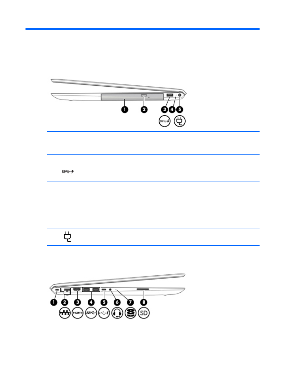
Right side
Component Description
(1) Optical drive Depending on your computer model, reads an optical disc or
reads and writes to an optical disc.
(2) Optical drive eject button Releases the optical drive disc tray.
(3) USB 3.x SuperSpeed port with HP Sleep and
(4) AC adapter and battery light
(5) Power connector Connects an AC adapter.
Left side
Charge
Connects a USB device, provides high-speed data transfer, and
even when the computer is o, charges most products such as a
cell phone, camera, activity tracker, or smartwatch.
●
White: The AC adapter is connected and the battery is fully
charged.
●
Blinking white: The AC adapter is disconnected and the
battery has reached a low battery level.
●
Amber: The AC adapter is connected and the battery is
charging.
●
O: The battery is not charging.
Right side 5
Page 14
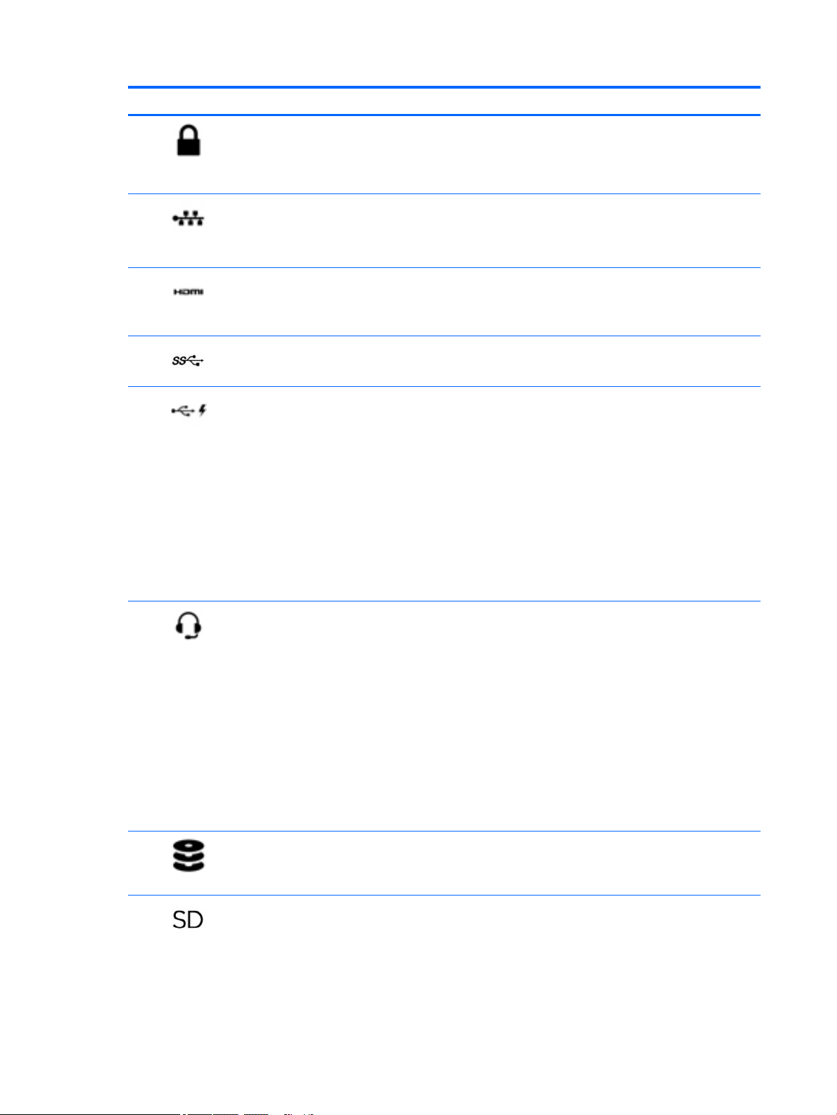
Component Description
(1) Security cable slot Attaches an optional security cable to the computer.
NOTE: The security cable is designed to act as a deterrent, but
it may not prevent the computer from being mishandled or
stolen.
(2) RJ-45 (network) jack/status lights Connects a network cable.
●
White: The network is connected.
●
Amber: Activity is occurring on the network.
(3) HDMI port Connects an optional video or audio device, such as a high-
denition television, any compatible digital or audio component,
or a high-speed High-Denition Multimedia Interface (HDMI)
device.
(4) USB 3.x SuperSpeed ports (2) Connect a USB device, such as a cell phone, camera, activity
tracker, or smartwatch, and provide high-speed data transfer.
(5) USB Type-C port with HP Sleep and Charge When the computer is on, connects and charges a USB device
that has a Type-C connector, such as a cell phone, camera,
activity tracker, or smartwatch, and provides high-speed data
transfer.
– or –
Connects to various USB, video, HDMI, and LAN devices.
NOTE: Cables and/or adapters (purchased separately) may be
required.
– or –
Connects a DisplayPort device that has a USB Type-C connector,
providing display output.
(6) Audio-out (headphone)/Audio-in (microphone)
combo jack
(7) Drive light
(8) Memory card reader Reads optional memory cards that enable you to store, manage,
Connects optional powered stereo speakers, headphones,
earbuds, a headset, or a television audio cable. Also connects an
optional headset microphone. This jack does not support
optional standalone microphones.
WARNING! To reduce the risk of personal injury, adjust the
volume before putting on headphones, earbuds, or a headset.
For additional safety information, refer to the Regulatory,
Safety, and Environmental Notices.
To access this guide:
▲ Select the Start button, select HP Help and Support, and
then select HP Documentation.
NOTE: When a device is connected to the jack, the computer
speakers are disabled.
●
Blinking white: The hard drive is being accessed.
●
Amber: HP 3D DriveGuard has temporarily parked the hard
drive.
share, or access information.
To insert a card:
1. Hold the card label-side up, with connectors facing the
computer.
6 Chapter 2 External component identication
Page 15

Component Description
2. Insert the card into the memory card reader, and then
press in on the card until it is rmly seated.
To remove a card:
▲ Press in on the card, and then remove it from the memory
card reader.
Left side 7
Page 16
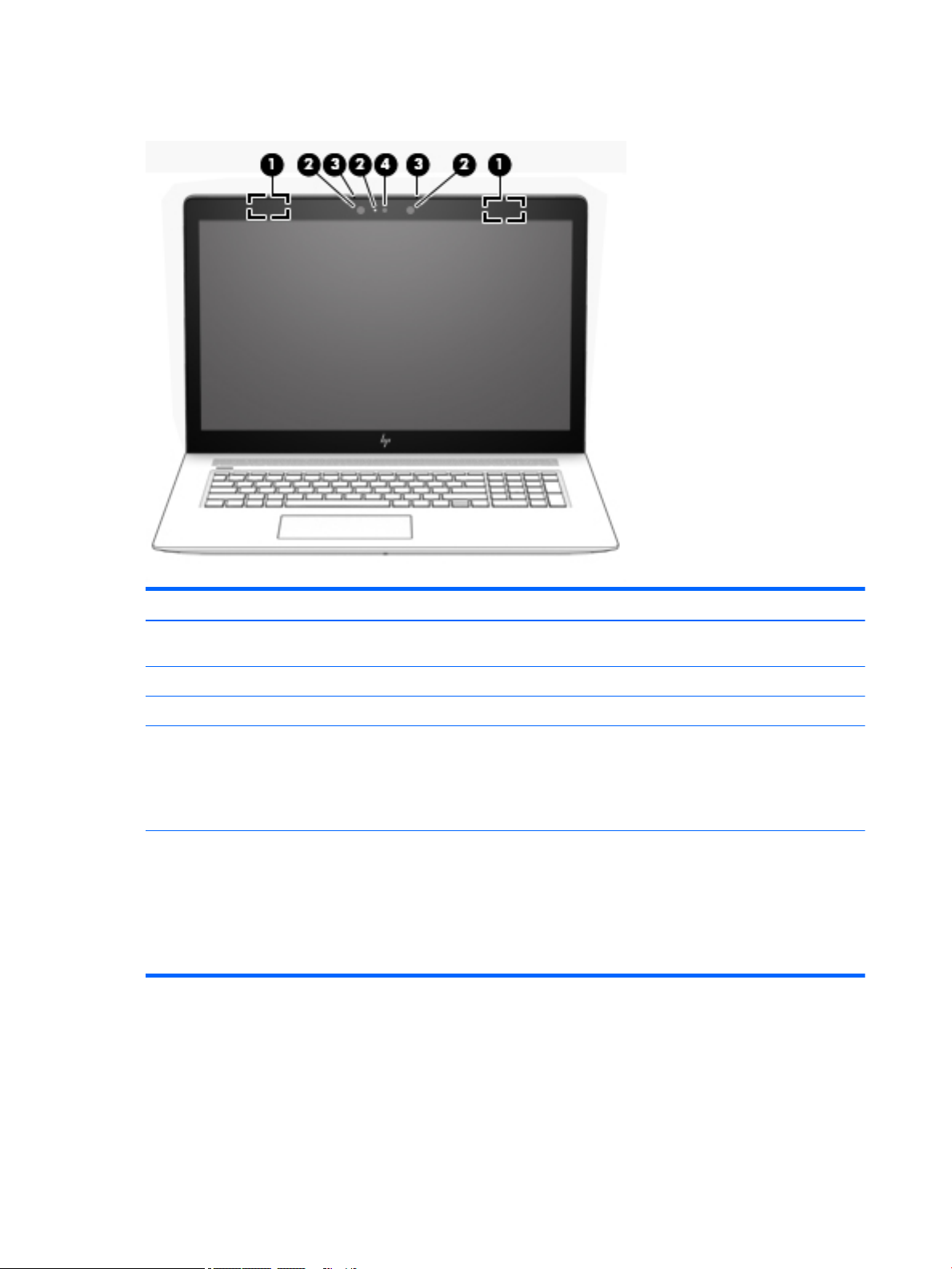
Display
Component Description
(1) WLAN antennas* (2) Send and receive wireless signals to communicate with wireless local
area networks (WLANs).
(2) Camera light(s) On: One or more cameras are in use.
(3) Internal microphones (2) Record sound.
(4) Camera(s) Allow you to video chat, record video, and record still images. Some
cameras also allow a facial recognition logon to Windows, instead of
a password logon.
NOTE: Camera functions vary depending on the camera hardware
and software installed on your product.
*The antennas are not visible from the outside of the computer, and antenna location varies. For optimal transmission, keep the areas
immediately around the antennas free from obstructions.
For wireless regulatory notices, see the section of the Regulatory, Safety, and Environmental Notices that applies to your country or
region.
To access this guide:
▲ Select the Start button, select HP Help and Support, and then select HP Documentation.
8 Chapter 2 External component identication
Page 17
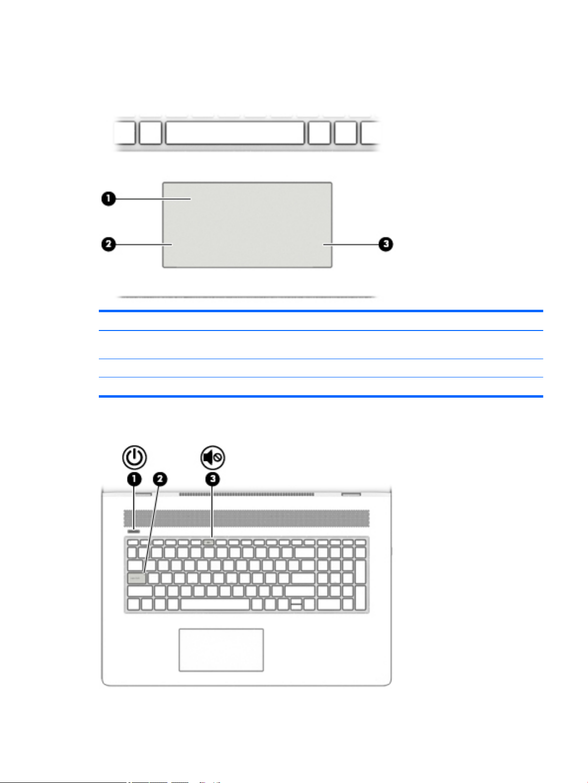
Keyboard area
TouchPad
Component Description
(1) TouchPad zone Reads your nger gestures to move the pointer or activate items
on the screen.
Lights
(2) Left TouchPad button Functions like the left button on an external mouse.
(3) Right TouchPad button Functions like the right button on an external mouse.
Keyboard area 9
Page 18
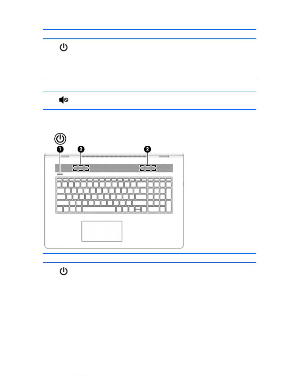
Component Description
(1) Power light
(2) Caps lock light On: Caps lock is on, which switches the key input to all capital
(3) Mute light
Button and speakers
●
On: The computer is on.
●
Blinking: The computer is in the Sleep state, a powersaving state. The computer shuts o power to the display
and other unneeded components.
●
O: The computer is o or in Hibernation. Hibernation is a
power-saving state that uses the least amount of power.
letters.
●
On: Computer sound is o.
●
O: Computer sound is on.
Component Description
(1) Power button
10 Chapter 2 External component identication
●
When the computer is o, press the button to turn on the
computer.
●
When the computer is on, press the button briey to
initiate Sleep.
●
When the computer is in the Sleep state, press the button
briey to exit Sleep.
●
When the computer is in Hibernation, press the button
briey to exit Hibernation.
CAUTION: Pressing and holding down the power button results
in the loss of unsaved information.
Page 19

Component Description
If the computer has stopped responding and shutdown
procedures are ineective, press and hold the power button
down for at least 5 seconds to turn o the computer.
To learn more about your power settings, see your power
options.
▲ Right-click the Start button, and then select Power
Options.
(2) Speakers Produce sound.
Keyboard area 11
Page 20
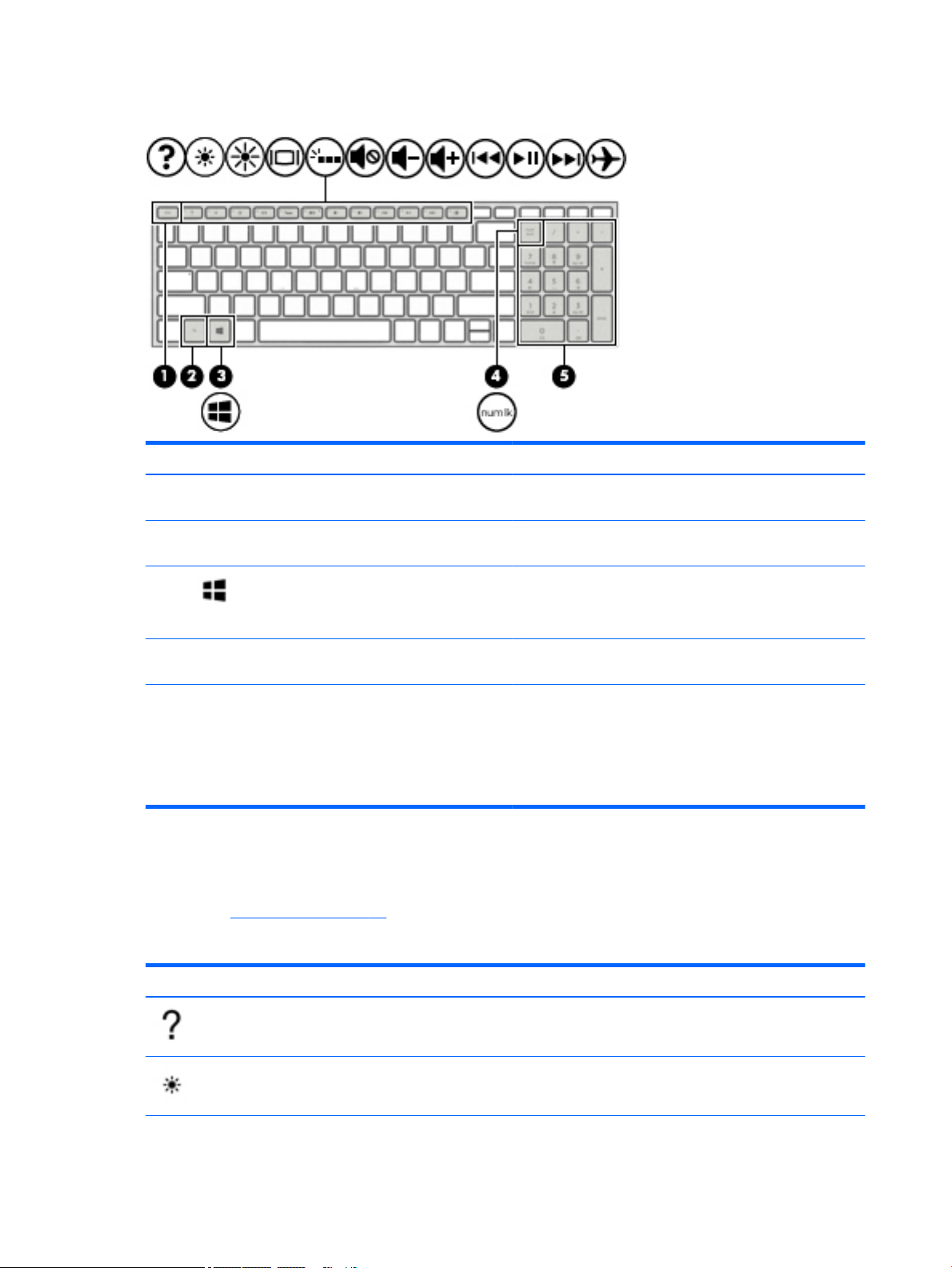
Special keys
Component Description
(1) esc key Displays system information when pressed in combination with
(2) fn key Executes specic functions when pressed in combination with
the fn key.
another key.
(3) Windows key Opens the Start menu.
(4) num lock key Alternates between the navigational and numeric functions on
(5) Integrated numeric keypad A separate keypad to the right of the alphabet keyboard. When
Action keys
An action key performs the function indicated by the icon on the key. To determine which keys are on your
product, see Special keys on page 12.
▲
Icon
NOTE: Pressing the Windows key again will close the Start
menu.
the integrated numeric keypad.
num lock is pressed, the keypad can be used like an external
numeric keypad.
NOTE: If the keypad function is active when the computer is
turned o, that function is reinstated when the computer is
turned back on.
To use an action key, press and hold the key.
Description
Opens the "How to get help in Windows 10" webpage.
Decreases the screen brightness incrementally as long as you hold down the key.
12 Chapter 2 External component identication
Page 21
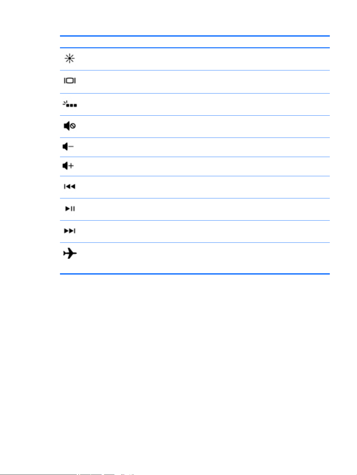
Icon Description
Increases the screen brightness incrementally as long as you hold down the key.
Switches the screen image between display devices connected to the system. For example, if a monitor is
connected to the computer, repeatedly pressing this key alternates the screen image from the computer
display to the monitor display to a simultaneous display on both the computer and the monitor.
Turns the keyboard backlight o or on.
NOTE: To conserve battery power, turn o this feature.
Mutes or restores speaker sound.
Decreases speaker volume incrementally while you hold down the key.
Increases speaker volume incrementally while you hold down the key.
Plays the previous track of an audio CD or the previous section of a DVD or a Blu-ray Disc (BD).
Starts, pauses, or resumes playback of an audio CD, a DVD, or a BD.
Plays the next track of an audio CD or the next section of a DVD or a BD.
Turns the airplane mode and wireless feature on or o.
NOTE: The airplane mode key is also referred to as the wireless button.
NOTE: A wireless network must be set up before a wireless connection is possible.
Keyboard area 13
Page 22
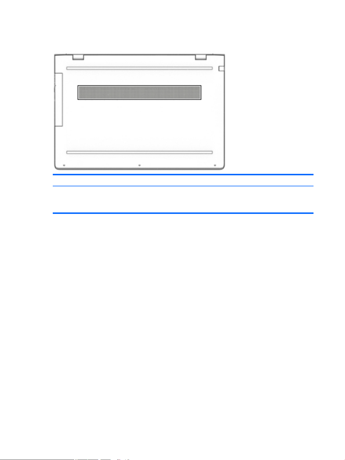
Bottom
Description
Vent Enables airow to cool internal components.
NOTE: The computer fan starts up automatically to cool internal components and prevent
overheating. It is normal for the internal fan to cycle on and o during routine operation.
14 Chapter 2 External component identication
Page 23
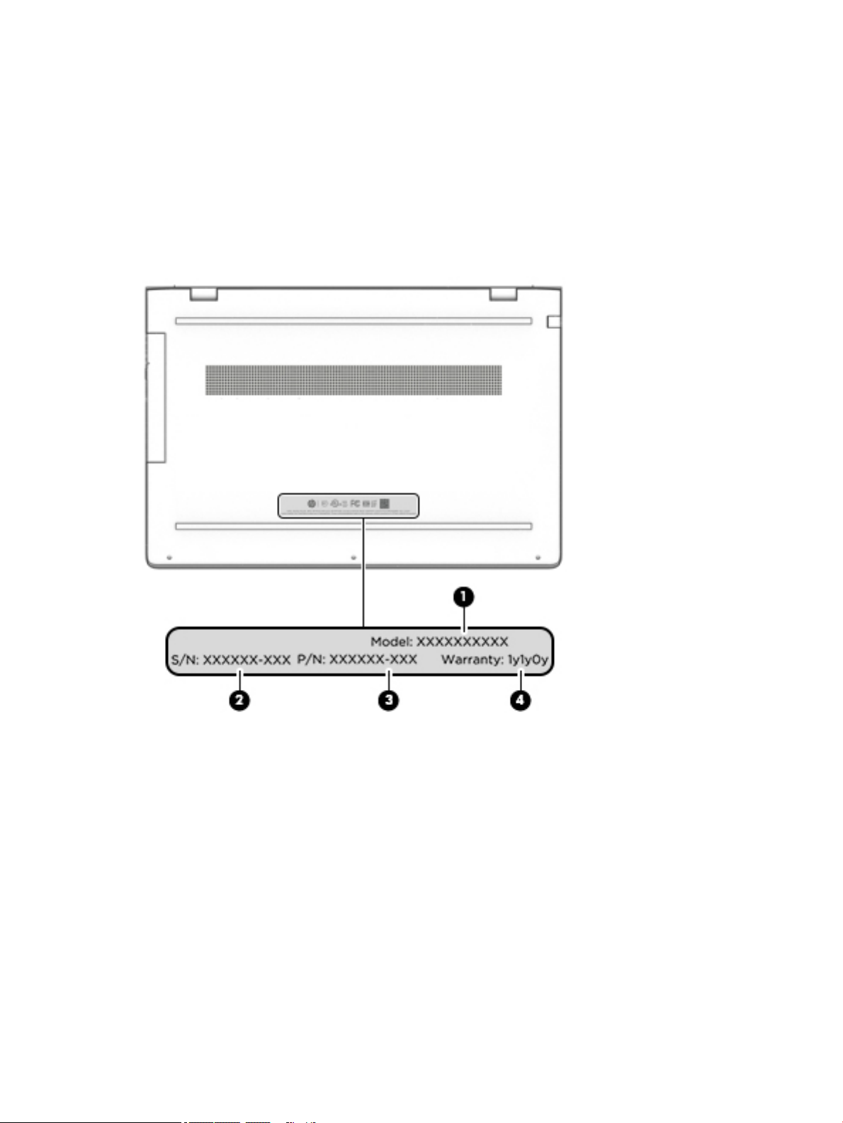
Locating system information
Important system information is located on the bottom edge of the tablet or on the keyboard base. You may
need the information when travelling internationally or when you contact support:
(1): Serial number
(2): Product number
(3): Model number
(4): Warranty period
Using Windows, briey press the fn+esc key combination to display the System Information screen, which
provides the product name and serial number of your computer, as well as information about the memory,
processor, BIOS, and keyboard.
Locating system information 15
Page 24

3 Illustrated parts catalog
Computer major components
NOTE: HP continually improves and changes product parts. For complete and current information on
supported parts for your computer, go to http://partsurfer.hp.com, select your country or region, and then
follow the on-screen instructions.
NOTE: Details about your computer, including model, serial number, product key, and length of warranty,
are on the service tag at the bottom of your computer. See Locating system information on page 15 for
details.
16 Chapter 3 Illustrated parts catalog
Page 25
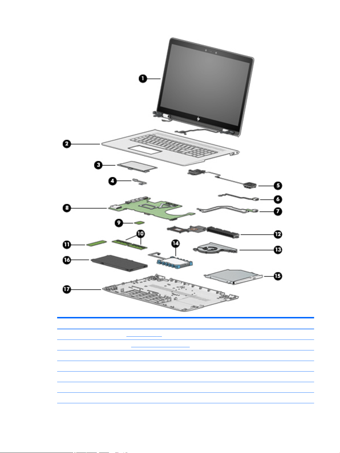
Item Component Spare part number
(1) Display assembly (see Display on page 29)
(2) Top cover/keyboard (see Top cover/keyboard on page 58)
(3) TouchPad module 935941-001
(4) TouchPad cable 925459-001
(5) Speakers 925476-001
(6) Power connector (includes cable) 810326-012
(7) USB board
Computer major components 17
Page 26

Item Component Spare part number
8L 925470-001
10L L02141-001
Cable, USB FFC 928573-001
Cable, USB 925458-001
(8) System board (see System board on page 50)
(9) WLAN module
WLAN Assembly, 11AC+BT INT 7265NV M.2 D1 MOW 901229-855
WLAN Assembly RT CARTIER AC 2X2 924813-855
(10) Memory
SODIMM 4 GB 2400 MHz 1.2v DDR4 862397-855
SODIMM 8 GB 2400 MHz 1.2v DDR4 862398-855
(11) Solid-state drive (see Solid-state drive on page 33)
(12) Heat sink 925478-001
(13) Fan 925461-001
(14) Hard drive 766644-005
(15) Optical drive 920417-005
(16) Battery 916814-855
(17) Base enclosure 925454-001
Miscellaneous parts
Component Spare part number
AC adapter, 90W 710413-001
AC adapter, 65W 854117-850
Adapter, HP HDMI to VGA 701943-001
Dongle, USB-C to USB-A 833960-001
Pen 910942-001
Hook 933393-001
Power cord, AC line, 1.0 m
For use in North America 213349-015
For use in Europe 213350-014
For use in the United Kingdom 213351-013
For use in Denmark 213353-013
18 Chapter 3 Illustrated parts catalog
Page 27

Component Spare part number
For use in Switzerland 213354-013
For use in South Africa 361240-007
For use in Israel 398063-008
For use in Israel 398063-008
Power cord, C5, 1.0 m
For use in North America 920689-001
For use in Europe 920689-005
For use in the United Kingdom 920689-006
For use in Denmark 920689-007
For use in Israel 920689-008
For use in Switzerland 920689-009
For use in South America 920689-010
Rubber kit 935940-001
Screw kit 925475-001
Miscellaneous parts 19
Page 28

4 Removal and replacement procedures
preliminary requirements
Tools required
You will need the following tools to complete the removal and replacement procedures:
●
Flat-bladed screwdriver
●
Magnetic screwdriver
●
Phillips P0 and P1 screwdrivers
Service considerations
The following sections include some of the considerations that you must keep in mind during disassembly
and assembly procedures.
NOTE: As you remove each subassembly from the computer, place the subassembly (and all accompanying
screws) away from the work area to prevent damage.
Plastic parts
CAUTION: Using excessive force during disassembly and reassembly can damage plastic parts. Use care
when handling the plastic
20 Chapter 4 Removal and replacement procedures preliminary requirements
Page 29

Cables and connectors
CAUTION: When servicing the computer, be sure that cables are placed in their proper locations during the
reassembly process. Improper cable placement can damage the computer.
Cables must be handled with extreme care to avoid damage. Apply only the tension required to unseat or seat
the cables during removal and insertion. Handle cables by the connector whenever possible. In all cases, avoid
bending, twisting, or tearing cables. Be sure that cables are routed in such a way that they cannot be caught
or snagged by parts being removed or replaced. Handle ex cables with extreme care; these cables tear
easily.
Drive handling
CAUTION: Drives are fragile components that must be handled with care. To prevent damage to the
computer, damage to a drive, or loss of information, observe these precautions:
Before removing or inserting a hard drive, shut down the computer. If you are unsure whether the computer is
o or in Hibernation, turn the computer on, and then shut it down through the operating system.
Before handling a drive, be sure that you are discharged of static electricity. While handling a drive, avoid
touching the connector.
Before removing an optical drive, be sure that a disc is not in the drive and be sure that the optical drive tray is
closed.
Handle drives on surfaces covered with at least one inch of shock-proof foam.
Avoid dropping drives from any height onto any surface.
After removing a hard drive or an optical drive, place it in a static-proof bag.
Avoid exposing an internal hard drive to products that have magnetic elds, such as monitors or speakers.
Avoid exposing a drive to temperature extremes or liquids.
If a drive must be mailed, place the drive in a bubble pack mailer or other suitable form of protective
packaging and label the package “FRAGILE.”
Service considerations 21
Page 30

Grounding guidelines
Electrostatic discharge damage
Electronic components are sensitive to electrostatic discharge (ESD). Circuitry design and structure determine
the degree of sensitivity. Networks built into many integrated circuits provide some protection, but in many
cases, ESD contains enough power to alter device parameters or melt silicon junctions.
A discharge of static electricity from a nger or other conductor can destroy static-sensitive devices or
microcircuitry. Even if the spark is neither felt nor heard, damage may have occurred.
An electronic device exposed to ESD may not be aected at all and can work perfectly throughout a normal
cycle. Or the device may function normally for a while, then degrade in the internal layers, reducing its life
expectancy.
CAUTION: To prevent damage to the computer when you are removing or installing internal components,
observe these precautions:
Keep components in their electrostatic-safe containers until you are ready to install them.
Before touching an electronic component, discharge static electricity by using the guidelines described in this
section.
Avoid touching pins, leads, and circuitry. Handle electronic components as little as possible.
If you remove a component, place it in an electrostatic-safe container.
The following table shows how humidity aects the electrostatic voltage levels generated by dierent
activities.
CAUTION: A product can be degraded by as little as 700 V.
Typical electrostatic voltage levels
Relative humidity
Event 10% 40% 55%
Walking across carpet 35,000 V 15,000 V 7,500 V
Walking across vinyl oor 12,000 V 5,000 V 3,000 V
Motions of bench worker 6,000 V 800 V 400 V
Removing DIPS from plastic tube 2,000 V 700 V 400 V
Removing DIPS from vinyl tray 11,500 V 4,000 V 2,000 V
Removing DIPS from plastic foam 14,500 V 5,000 V 3,500 V
Removing bubble pack from PCB 26,500 V 20,000 V 7,000 V
Packing PCBs in foam-lined box 21,000 V 11,000 V 5,000 V
22 Chapter 4 Removal and replacement procedures preliminary requirements
Page 31

Packaging and transporting guidelines
Follow these grounding guidelines when packaging and transporting equipment:
●
To avoid hand contact, transport products in static-safe tubes, bags, or boxes.
●
Protect ESD-sensitive parts and assemblies with conductive or approved containers or packaging.
●
Keep ESD-sensitive parts in their containers until the parts arrive at static-free workstations.
●
Place items on a grounded surface before removing items from their containers.
●
Always be properly grounded when touching a component or assembly.
●
Store reusable ESD-sensitive parts from assemblies in protective packaging or nonconductive foam.
●
Use transporters and conveyors made of antistatic belts and roller bushings. Be sure that mechanized
equipment used for moving materials is wired to ground and that proper materials are selected to avoid
static charging. When grounding is not possible, use an ionizer to dissipate electric charges.
Workstation guidelines
Follow these grounding workstation guidelines:
●
Cover the workstation with approved static-shielding material.
●
Use a wrist strap connected to a properly grounded work surface and use properly grounded tools and
equipment.
●
Use conductive eld service tools, such as cutters, screwdrivers, and vacuums.
●
When xtures must directly contact dissipative surfaces, use xtures made only of static safe materials.
●
Keep the work area free of nonconductive materials, such as ordinary plastic assembly aids and plastic
foam.
●
Handle ESD-sensitive components, parts, and assemblies by the case or PCM laminate. Handle these
items only at static-free workstations.
●
Avoid contact with pins, leads, or circuitry.
●
Turn o power and input signals before inserting or removing connectors or test equipment.
Grounding guidelines 23
Page 32

Equipment guidelines
Grounding equipment must include either a wrist strap or a foot strap at a grounded workstation.
●
When seated, wear a wrist strap connected to a grounded system. Wrist straps are exible straps with a
minimum of one megohm ±10% resistance in the ground cords. To provide proper ground, wear a strap
snugly against the skin at all times. On grounded mats with banana-plug connectors, use alligator clips
to connect a wrist strap.
●
When standing, use foot straps and a grounded oor mat. Foot straps (heel, toe, or boot straps) can be
used at standing workstations and are compatible with most types of shoes or boots. On conductive
oors or dissipative oor mats, use foot straps on both feet with a minimum of one megohm resistance
between the operator and ground. To be eective, the conductive equipment must be worn in contact
with the skin.
The following grounding equipment is recommended to prevent electrostatic damage:
●
Antistatic tape
●
Antistatic smocks, aprons, and sleeve protectors
●
Conductive bins and other assembly or soldering aids
●
Nonconductive foam
●
Conductive tabletop workstations with ground cords of one megohm resistance
●
Static-dissipative tables or oor mats with hard ties to the ground
●
Field service kits
●
Static awareness labels
●
Material-handling packages
●
Nonconductive plastic bags, tubes, or boxes
●
Metal tote boxes
●
Electrostatic voltage levels and protective materials
The following table lists the shielding protection provided by antistatic bags and oor mats.
Material Use Voltage protection level
Antistatic plastics Bags 1,500 V
Carbon-loaded plastic Floor mats 7,500 V
Metallized laminate Floor mats 5,000 V
24 Chapter 4 Removal and replacement procedures preliminary requirements
Page 33

5 Removal and replacement procedures for
authorized service provider parts
CAUTION: Components described in this chapter should be accessed only by an authorized service provider.
Accessing these parts can damage the computer or void the warranty.
CAUTION: This computer does not have user-replaceable parts. Only HP authorized service providers should
perform the removal and replacement procedures described here. Accessing the internal part could damage
the computer or void the warranty.
Component replacement procedures
NOTE: Details about your computer, including model, serial number, product key, and length of warranty,
are on the service tag at the bottom of your computer. See Locating system information on page 15 for
details.
NOTE: HP continually improves and changes product parts. For complete and current information on
supported parts for your computer, go to http://partsurfer.hp.com, select your country or region, and then
follow the on-screen instructions.
There are as many as 62 screws that must be removed, replaced, and/or loosened when servicing the parts
described in this chapter. Make special note of each screw size and location during removal and replacement.
Component replacement procedures 25
Page 34

Base enclosure
Description Spare part number
Base enclosure 925454-001
IMPORTANT: Make special note of each screw and screw lock size and location during removal and
replacement
Before removing the base enclosure, follow these steps:
1. Shut down the computer.
2. Disconnect all external devices connected to the computer.
3. Disconnect the power from the computer by rst unplugging the power cord from the AC outlet and then
unplugging the AC adapter from the computer.
Remove the base enclosure:
1. Insert a paper clip(1) to release the optical drive, slide the optical drive out (2), and then remove the
screw (3).
2. Remove the rubber strip (1).
3. Remove 3 screws under the rubber strip (2).
4. Remove 4 screws (3).
26 Chapter 5 Removal and replacement procedures for authorized service provider parts
Page 35

5. Lift the base enclosure (4), and then remove it (5).
Reverse this procedure to install the base enclosure.
Component replacement procedures 27
Page 36

Battery
Description Spare part number
Battery, 3-cell 55Whr 4.8Ah LI LK03055XL-PR 916814-855
IMPORTANT: Make special note of each screw and screw lock size and location during removal and
replacement
Before removing the battery, follow these steps:
1. Shut down the computer.
2. Disconnect all external devices connected to the computer.
3. Disconnect the power from the computer by rst unplugging the power cord from the AC outlet and then
unplugging the AC adapter from the computer.
4. Remove the base enclosure (see Base enclosure on page 26)
Remove the battery:
▲
Remove 7 screws (1), and then lift the battery (2) to remove it.
Reverse this procedure to install the battery.
28 Chapter 5 Removal and replacement procedures for authorized service provider parts
Page 37

Display
Description Spare part number
Hinge-up Kit
HU LCD 17.3 FHD AG UWVA (Touch screen) 925547-001
HU LCD 17.3 FHD AG UWVA 935938-001
LCD 17.3 UHD AG UWVA with bezel 935939-001
Hinge covers 933394-001
IMPORTANT: Make special note of each screw and screw lock size and location during removal and
replacement
Before removing the display panel, follow these steps:
1. Turn o the computer. If you are unsure whether the computer is o or in Hibernation, turn the
computer on, and then shut it down through the operating system.
2. Disconnect the power from the computer by unplugging the power cord from the computer.
3. Disconnect all external devices from the computer.
4. Remove the base enclosureBase enclosure on page 26).
5. Remove the battery (see Battery on page 28).
6. Remove the following components:
a. Base enclosure (see Base enclosure on page 26).
b. Battery (see Battery on page 28).
Remove the display assembly:
▲
Remove three screws from each hinge bracket (1), turn the display assembly over (2), and then lift the
display to remove it (e).
Component replacement procedures 29
Page 38

Reverse this procedure to replace the display assembly.
30 Chapter 5 Removal and replacement procedures for authorized service provider parts
Page 39

Hard drive
Description Spare part number
Hard drive, 1TB 7200 RPM SATA RAW 9.5mm 766644-005
Cable, hard drive 925456-001
Rubber, sleeve holder 925465-001
IMPORTANT: Make special note of each screw and screw lock size and location during removal and
replacement
Before removing the hard drive, follow these steps:
1. Shut down the computer.
2. Disconnect all external devices connected to the computer.
3. Disconnect the power from the computer by rst unplugging the power cord from the AC outlet and then
4. Remove the following components:
unplugging the AC adapter from the computer.
a. Base enclosure (see Base enclosure on page 26).
b. Battery (see Battery on page 28).
Remove the hard drive:
1. Disconnect the hard drive cable from the system board(1).
2. Lift the hard drive cable (2), and then lift the hard drive (3) to remove it.
Component replacement procedures 31
Page 40

If it is necessary to disassemble the hard drive:
▲
Remove the hard drive cable (1), remove the plastic hard drive bracket (2), and then lift the hard drive
bracket (3) to remove it.
Reverse this procedure to install the hard drive.
32 Chapter 5 Removal and replacement procedures for authorized service provider parts
Page 41

Solid-state drive
Description Spare part number
Solid-state drive
SSD128 GB 2280 M2 SATA3 Value RS 827560-043
SSD 256 GB 2280 M2 PCIe3x4SS NVMeTLC RS 847109-019
SSD 512 GB 2280 M2 PCIe3x4SS NVMeTLC RS 847110-016
SSD1 TB 2280 PCIe-3x4NVMe TLC 2Side RS 865697-008
SSD 360 GB 2280 PCIe3x4 NVMe TLC RS 917818-010
SSD 256 GB 2280 PCIe NVMe Value RS 933705-001
SSD 512 GB 2280 PCIe NVMe Value RS 933706-001
IMPORTANT: Make special note of each screw and screw lock size and location during removal and
replacement
Before removing the solid-state drive, follow these steps:
1. Shut down the computer.
2. Disconnect all external devices connected to the computer.
3. Disconnect the power from the computer by rst unplugging the power cord from the AC outlet and then
unplugging the AC adapter from the computer.
4. Remove the following components:
a. Base enclosure (see Base enclosure on page 26).
b. Battery (see Battery on page 28).
c. Hard drive (see Hard drive on page 31).
Remove the solid-state drive:
1. Remove the Phillips screw (1) that secures the solid-state drive to the system board.
Component replacement procedures 33
Page 42

2. Remove the solid-state drive (2) by pulling the drive away from the slot at an angle.
Reverse this procedure to install the solid-state drive.
34 Chapter 5 Removal and replacement procedures for authorized service provider parts
Page 43

Memory
Description Spare part number
Memory
SODIMM 4 GB 2400 MHz 1.2v DDR4 862397-855
SODIMM 8 GB 2400 MHz 1.2v DDR4 862398-855
IMPORTANT: Make special note of each screw and screw lock size and location during removal and
replacement
Before removing the memory, follow these steps:
1. Shut down the computer.
2. Disconnect all external devices connected to the computer.
3. Disconnect the power from the computer by rst unplugging the power cord from the AC outlet and then
unplugging the AC adapter from the computer.
4. Remove the following components:
a. Base enclosure (see Base enclosure on page 26).
b. Battery (see Battery on page 28).
c. Hard drive (see Hard drive on page 31).
d. Solid-state drive (see Solid-state drive on page 33).
Remove the memory:
1. Spread the retaining tabs (1) on each side of the memory module slot to release the memory module.
(The memory module tilts up.) .
2. Remove the memory module (2) by pulling the module away from the slot at an angle.
Component replacement procedures 35
Page 44

Reverse this procedure to install the memory.
36 Chapter 5 Removal and replacement procedures for authorized service provider parts
Page 45

WLAN module
Description Spare part number
WLAN module
11 AC+Bluetooth INT 7265NV M.2 D1 MOW 901229-855
RT CARTIER AC 2X2 924813-855
IMPORTANT: Make special note of each screw and screw lock size and location during removal and
replacement
CAUTION: To prevent an unresponsive system, replace the wireless module only with a wireless module
authorized for use in the computer by the governmental agency that regulates wireless devices in your
country or region. If you replace the module and then receive a warning message, remove the module to
restore device functionality, and then contact technical support.
Before removing the WLAN module, follow these steps:
1. Shut down the computer.
2. Disconnect all external devices connected to the computer.
3. Disconnect the power from the computer by rst unplugging the power cord from the AC outlet and then
unplugging the AC adapter from the computer.
4. Remove the following components:
a. Base enclosure (see Base enclosure on page 26).
b. Battery (see Battery on page 28).
c. Hard drive (see Hard drive on page 31).
d. Solid-state drive (see Solid-state drive on page 33).
e. Memory (see Memory on page 35).
Remove the WLAN module:
1. Disconnect the WLAN antenna cables (1) from the terminals on the WLAN module.
NOTE: The WLAN antenna cable labeled “1” connects to the WLAN module “Main” terminal labeled “1”.
The WLAN antenna cable labeled “2” connects to the WLAN module “Aux” terminal labeled “2”.
2. Remove the Phillips screw (2) that secures the WLAN module to the system board. (The WLAN module
tilts up.)
Component replacement procedures 37
Page 46

3. Remove the WLAN module (3) by pulling the module away from the slot at an angle.
NOTE: If the WLAN antenna cables are not connected to the terminals on the WLAN module, protective
sleeves should be installed on the antenna connectors, as shown in the following illustration.
Reverse this procedure to install the WLAN module.
38 Chapter 5 Removal and replacement procedures for authorized service provider parts
Page 47

Optical drive
Description Spare part number
ODD DVD-Writer 9.0mm Tray 920417-005
Bracket, ODD left 925464-001
Bracket, ODD right 931742-001
Bezel, ODD 925455-001
IMPORTANT: Make special note of each screw and screw lock size and location during removal and
replacement
Before removing the optical drive, follow these steps:
1. Shut down the computer.
2. Disconnect all external devices connected to the computer.
3. Disconnect the power from the computer by rst unplugging the power cord from the AC outlet and then
unplugging the AC adapter from the computer.
4. Remove the following components:
a. Base enclosure (see Base enclosure on page 26).
b. Battery (see Battery on page 28).
c. Hard drive (see Hard drive on page 31).
d. Solid-state drive (see Solid-state drive on page 33).
e. Memory (see Memory on page 35).
f. WLAN module (see WLAN module on page 37).
Remove the optical drive:
▲
Remove 3 screws (1), disconnect the optical drive cable(2), and then slide the optical drive out (3) to
remove it.
Component replacement procedures 39
Page 48

If it is necessary to remove the optical drive bracket:
▲
Remove 3 screws (1), and then remove the optical drive brackets(2).
Reverse this procedure to install the optical drive.
40 Chapter 5 Removal and replacement procedures for authorized service provider parts
Page 49

Input/output brackets
Description Spare part number
Bracket, right input/output 925462-001
Bracket, left input/output 925463-001
IMPORTANT: Make special note of each screw and screw lock size and location during removal and
replacement
Before removing the Input/out brackets, follow these steps:
1. Shut down the computer.
2. Disconnect all external devices connected to the computer.
3. Disconnect the power from the computer by rst unplugging the power cord from the AC outlet and then
unplugging the AC adapter from the computer.
4. Remove the following components:
a. Base enclosure (see Base enclosure on page 26).
b. Battery (see Battery on page 28).
c. Hard drive (see Hard drive on page 31).
d. Solid-state drive (see Solid-state drive on page 33).
e. Memory (see Memory on page 35).
f. WLAN module (see WLAN module on page 37).
g. Optical drive (see Optical drive on page 39).
Remove the left input/output bracket:
1. Remove 1 screw (1).
Component replacement procedures 41
Page 50

2. Remove 2 screws (2), and then lift the left I/O bracket (3) to remove it.
Remove the right input/output bracket:
▲
Remove 1 screw(1), and then lift the right I/O bracket (2) to remove it.
Reverse this procedure to install the input/output brackets.
42 Chapter 5 Removal and replacement procedures for authorized service provider parts
Page 51

Fan
Description Spare part number
Fan 925461-001
Heat sink 925478-001
IMPORTANT: Make special note of each screw and screw lock size and location during removal and
replacement
Before removing the fan, follow these steps:
1. Shut down the computer.
2. Disconnect all external devices connected to the computer.
3. Disconnect the power from the computer by rst unplugging the power cord from the AC outlet and then
unplugging the AC adapter from the computer.
4. Remove the following components:
a. Base enclosure (see Base enclosure on page 26).
b. Battery (see Battery on page 28).
c. Hard drive (see Hard drive on page 31).
d. Solid-state drive (see Solid-state drive on page 33).
e. Memory (see Memory on page 35).
f. WLAN module (see WLAN module on page 37).
g. Optical drive (see Optical drive on page 39).
Remove the fan:
1. Disconnect the fan cable from the system board (1).
2. Remove 3 screws (2).
Component replacement procedures 43
Page 52

3. Release the fan cable from the routing (3), and then lift the fan (4) to remove it.
Reverse this procedure to install the fan.
44 Chapter 5 Removal and replacement procedures for authorized service provider parts
Page 53

TouchPad
IMPORTANT: Make special note of each screw and screw lock size and location during removal and
replacement
Before removing the TouchPad, follow these steps:
1. Shut down the computer.
2. Disconnect all external devices connected to the computer.
3. Disconnect the power from the computer by rst unplugging the power cord from the AC outlet and then
4. Remove the following components:
Description Spare part number
TouchPad 935941-001
TouchPad bracket 925466-001
unplugging the AC adapter from the computer.
a. Base enclosure (see Base enclosure on page 26).
b. Battery (see Battery on page 28).
c. Hard drive (see Hard drive on page 31).
d. Solid-state drive (see Solid-state drive on page 33).
e. Memory (see Memory on page 35).
f. WLAN module (see WLAN module on page 37).
g. Optical drive (see Optical drive on page 39).
Remove the TouchPad:
1. Remove 4 screws (1), and then lift the bracket (2) to remove it.
Component replacement procedures 45
Page 54

2. Disconnect the TouchPad cable (1), and then release the cable (2).
3. Remove 3 screws (3), and then lift the TouchPad (4) to remove it.
46 Chapter 5 Removal and replacement procedures for authorized service provider parts
Page 55

4. Disconnect the TouchPad cable from the system board (1) and the TouchPad (2), release the cable (3),
and then lift the TouchPad cable (4) to remove it.
Reverse this procedure to install the TouchPad.
Component replacement procedures 47
Page 56

USB board
Description Spare part number
USB board, 8L 925470-001
USB board, 10L L02141-001
Cable, USB FFC 928573-001
Cable, USB 925458-001
IMPORTANT: Make special note of each screw and screw lock size and location during removal and
replacement
Before removing the USB board, follow these steps:
1. Shut down the computer.
2. Disconnect all external devices connected to the computer.
3. Disconnect the power from the computer by rst unplugging the power cord from the AC outlet and then
4. Remove the following components:
unplugging the AC adapter from the computer.
a. Base enclosure (see Base enclosure on page 26).
b. Battery (see Battery on page 28).
c. Hard drive (see Hard drive on page 31).
d. Solid-state drive (see Solid-state drive on page 33).
e. Memory (see Memory on page 35).
f. WLAN module (see WLAN module on page 37).
g. Optical drive (see Optical drive on page 39).
h. System board (see System board on page 50).
Remove the USB board:
1. Disconnect the webcam cable (1) and the USB cable (2) from the system board.
2. Release the cable from the routing (3).
3. Release the USB cable from the tape holding it (4).
4. Remove 1 screw (5).
48 Chapter 5 Removal and replacement procedures for authorized service provider parts
Page 57

5. Lift the USB board to remove it (6).
Reverse this procedure to install the USB board.
Component replacement procedures 49
Page 58

System board
Description Spare part number
System board
Discrete graphics 940MX 2 GB i5-7200U 925395-001
Discrete graphics 940MX 2 GB i5-7200U and the Windows operating system 925395-601
Discrete graphics 940MX 2 GB i7-7500U 925396-001
Discrete graphics 940MX 2 GB i7-7500U and the Windows operating system 925396-601
Discrete graphics 940MX 4 GB i7-7500U 925397-001
Discrete graphics 940MX 4 GB i7-7500U and the Windows operating system 925397-601
Discrete graphics MX150 2 GB i5-8250U 940818-001
Discrete graphics MX150 2 GB i5-8250U and the Windows operating system 940818-601
Discrete graphics MX150 2 GB i7-8550U 940819-001
Discrete graphics MX150 2 GB i7-8550U and the Windows operating system 940819-601
Discrete graphics MX150 4 GB i7-8550U 940820-001
Discrete graphics MX150 4 GB i7-8550U and the Windows operating system 940820-601
IMPORTANT: Make special note of each screw and screw lock size and location during removal and
replacement
Before removing the system board, follow these steps:
1. Shut down the computer.
2. Disconnect all external devices connected to the computer.
3. Disconnect the power from the computer by rst unplugging the power cord from the AC outlet and then
unplugging the AC adapter from the computer.
4. Remove the following components:
a. Base enclosure (see Base enclosure on page 26).
b. Battery (see Battery on page 28).
c. Hard drive (see Hard drive on page 31).
d. Solid-state drive (see Solid-state drive on page 33).
e. Memory (see Memory on page 35).
f. WLAN module (see WLAN module on page 37).
g. Optical drive (see Optical drive on page 39).
Disconnect the following cables from the system board:
1. Panel cable (1)
2. Touch board (2)
3. Webcam cable and USB board cable(3)
50 Chapter 5 Removal and replacement procedures for authorized service provider parts
Page 59

4. USB board ribbon cable (4)
5. Backlit cable (75)
6. Keyboard cable (6)
7. Hard drive cable (7)
8. TouchPad cable (8)
9. WLAN antenna cable (9)
10. Speaker cable (10)
Remove the system board:
▲
Remove 6 screws (1), lift the system board (2), and then remove it (3).
Component replacement procedures 51
Page 60

Reverse this procedure to install the system board.
52 Chapter 5 Removal and replacement procedures for authorized service provider parts
Page 61

Heat sink
IMPORTANT: Make special note of each screw and screw lock size and location during removal and
replacement
Before removing the heat sink, follow these steps:
1. Shut down the computer.
2. Disconnect all external devices connected to the computer.
3. Disconnect the power from the computer by rst unplugging the power cord from the AC outlet and then
4. Remove the following components:
Description Spare part number
Heat sink 925478-001
unplugging the AC adapter from the computer.
a. Base enclosure (see Base enclosure on page 26).
b. Battery (see Battery on page 28).
c. Hard drive (see Hard drive on page 31).
d. Solid-state drive (see Solid-state drive on page 33).
e. Memory (see Memory on page 35).
f. WLAN module (see WLAN module on page 37).
g. Optical drive (see Optical drive on page 39).
h. System board (see System board on page 50).
Remove the heat sink:
1. Remove 7 screws holding the heat sink (1) to the system board.
Component replacement procedures 53
Page 62

2. Lift the heat sink to remove it (2).
Thermal material locations are shown as follows:
Reverse this procedure to install the heat sink.
54 Chapter 5 Removal and replacement procedures for authorized service provider parts
Page 63

Speakers
IMPORTANT: Make special note of each screw and screw lock size and location during removal and
replacement
Before removing the speakers, follow these steps:
1. Shut down the computer.
2. Disconnect all external devices connected to the computer.
3. Disconnect the power from the computer by rst unplugging the power cord from the AC outlet and then
4. Remove the following components:
Description Spare part number
Speaker Kit 925476-001
unplugging the AC adapter from the computer.
a. Base enclosure (see Base enclosure on page 26).
b. Battery (see Battery on page 28).
c. Hard drive (see Hard drive on page 31).
d. Solid-state drive (see Solid-state drive on page 33).
e. Memory (see Memory on page 35).
f. WLAN module (see WLAN module on page 37).
g. Optical drive (see Optical drive on page 39).
h. System board (see System board on page 50).
Remove the speakers:
1. Remove the tapes holding the speaker cable(1).
2. Release the speaker cable from the routing (2).
3. Release the display cable from the routing (3).
Component replacement procedures 55
Page 64

4. Lift the speakers to remove them (4).
Reverse this procedure to install the speakers.
56 Chapter 5 Removal and replacement procedures for authorized service provider parts
Page 65

Power connector
Description Spare part number
Power connector (includes cable) 810326-012
IMPORTANT: Make special note of each screw and screw lock size and location during removal and
replacement
Before removing the speakers, follow these steps:
1. Shut down the computer.
2. Disconnect all external devices connected to the computer.
3. Disconnect the power from the computer by rst unplugging the power cord from the AC outlet and then
unplugging the AC adapter from the computer.
4. Remove the following components:
a. Base enclosure (see Base enclosure on page 26).
b. Battery (see Battery on page 28).
c. Hard drive (see Hard drive on page 31).
d. Solid-state drive (see Solid-state drive on page 33).
e. Memory (see Memory on page 35).
f. WLAN module (see WLAN module on page 37).
g. Optical drive (see Optical drive on page 39).
h. System board (see System board on page 50).
Remove the power connector:
1. Disconnect the power connector cable (1).
2. Release the power connector cable from the routing (2).
Component replacement procedures 57
Page 66

3. Lift the power connector to remove it (3).
Reverse this procedure to install the power connector.
Top cover/keyboard
The top cover/keyboard spare part kit includes the top cover, keyboard, and keyboard cable.
For use in country or region Spare part number For use in country or region Spare part number
For use in the United States 925477-001 For use in Russia 925477-251
For use in the United Kingdom 925477-031 For use in Romania 925477-271
For use in Germany 925477-041 For use in Belgium 925477-A41
For use in France 925477-051 For use internationally 925477-B31
For use in Italy 925477-061 For use in Slovenia 925477-BA1
For use in Spain 925477-071 For use in Israel 925477-BB1
For use in Portugal 925477-131 For use in Switzerland 925477-BG1
For use in Turkey 925477-141 For use in Canada 925477-DB1
For use in Greece 925477-151 For use in Denmark, Norway,
For use in Saudi Arabia 925477-171 For use in the Czech Republic
For use in Hungary 925477-211
925477-DH1
Finland, and Sweden
925477-FL1
and Slovakia
The top cover/keyboard spare part remains after all other spare parts have been removed.
58 Chapter 5 Removal and replacement procedures for authorized service provider parts
Page 67

6 Using Setup Utility (BIOS)
Setup Utility, or Basic Input/Output System (BIOS), controls communication between all the input and output
devices on the system (such as disk drives, display, keyboard, mouse, and printer). Setup Utility (BIOS)
includes settings for the types of devices installed, the startup sequence of the computer, and the amount of
system and extended memory.
NOTE: To start Setup Utility on convertible computers, your computer must be in notebook mode and you
must use the keyboard attached to your notebook.
Starting Setup Utility (BIOS)
CAUTION: Use extreme care when making changes in Setup Utility (BIOS). Errors can prevent the computer
from operating properly.
▲ Turn on or restart the computer, quickly press esc, and then press f10.
Updating Setup Utility (BIOS)
Updated versions of Setup Utility (BIOS) may be available on the HP website.
Most BIOS updates on the HP website are packaged in compressed les called SoftPaqs.
Some download packages contain a le named Readme.txt, which contains information regarding installing
and troubleshooting the le.
Determining the BIOS version
To decide whether you need to update Setup Utility (BIOS), rst determine the BIOS version on your computer.
To reveal the BIOS version information (also known as ROM date and System BIOS), use one of these options.
●
HP Support Assistant
1. Type support in the taskbar search box, and then select the HP Support Assistant app.
– or –
Click the question mark icon in the taskbar.
2. Select My PC, and then select Specications.
●
Setup Utility (BIOS)
1. Start Setup Utility (BIOS) (see Starting Setup Utility (BIOS) on page 59).
2. Select Main, select System Information, and then make note of the BIOS version.
3. Select Exit, select No, and then follow the on-screen instructions.
To check for later BIOS versions, see Downloading a BIOS update on page 60.
Starting Setup Utility (BIOS) 59
Page 68

Downloading a BIOS update
CAUTION: To reduce the risk of damage to the computer or an unsuccessful installation, download and
install a BIOS update only when the computer is connected to reliable external power using the AC adapter. Do
not download or install a BIOS update while the computer is running on battery power, docked in an optional
docking device, or connected to an optional power source. During the download and installation, follow these
instructions:
●
Do not disconnect power from the computer by unplugging the power cord from the AC outlet.
●
Do not shut down the computer or initiate Sleep.
●
Do not insert, remove, connect, or disconnect any device, cable, or cord.
NOTE: If your computer is connected to a network, consult the network administrator before installing any
software updates, especially system BIOS updates.
1. Type support in the taskbar search box, and then select the HP Support Assistant app.
– or –
Click the question mark icon in the taskbar.
2. Click Updates, and then click Check for updates and messages.
3. Follow the on-screen instructions.
4. At the download area, follow these steps:
a. Identify the most recent BIOS update and compare it to the BIOS version currently installed on your
computer. If the update is more recent than your BIOS version, make a note of the date, name, or
other identier. You may need this information to locate the update later, after it has been
downloaded to your hard drive.
b. Follow the on-screen instructions to download your selection to the hard drive.
Make a note of the path to the location on your hard drive where the BIOS update is downloaded.
You will need to access this path when you are ready to install the update.
BIOS installation procedures vary. Follow any instructions that appear on the screen after the download is
complete. If no instructions appear, follow these steps:
1. Type file in the taskbar search box, and then select File Explorer.
2. Click your hard drive designation. The hard drive designation is typically Local Disk (C:).
3. Using the hard drive path you recorded earlier, open the folder that contains the update.
4. Double-click the le that has an .exe extension (for example, lename.exe).
The BIOS installation begins.
5. Complete the installation by following the on-screen instructions.
NOTE: After a message on the screen reports a successful installation, you can delete the downloaded le
from your hard drive.
60 Chapter 6 Using Setup Utility (BIOS)
Page 69

7 Using HP PC Hardware Diagnostics (UEFI)
HP PC Hardware Diagnostics is a Unied Extensible Firmware Interface (UEFI) that allows you to run diagnostic
tests to determine whether the computer hardware is functioning properly. The tool runs outside the
operating system so that it can isolate hardware failures from issues that are caused by the operating system
or other software components.
When HP PC Hardware Diagnostics (UEFI) detects a failure that requires hardware replacement, a 24-digit
Failure ID code is generated. This ID code can then be provided to support to help determine how to correct
the problem.
NOTE: To start diagnostics on a convertible computer, your computer must be in notebook mode and you
must use the keyboard attached.
To start HP PC Hardware Diagnostics (UEFI), follow these steps:
1. Turn on or restart the computer, and quickly press esc.
2. Press f2.
The BIOS searches three places for the diagnostic tools, in the following order:
a. Connected USB drive
NOTE: To download the HP PC Hardware Diagnostics (UEFI) tool to a USB drive, see Downloading
HP PC Hardware Diagnostics (UEFI) to a USB device on page 62.
b. Hard drive
c. BIOS
3. When the diagnostic tool opens, select the type of diagnostic test you want to run, and then follow the
on-screen instructions.
NOTE: If you need to stop a diagnostic test, press esc.
61
Page 70

Downloading HP PC Hardware Diagnostics (UEFI) to a USB device
NOTE: The HP PC Hardware Diagnostics (UEFI) download instructions are provided in English only, and you
must use a Windows computer to download and create the HP UEFI support environment because only .exe
les are oered.
There are two options to download HP PC Hardware Diagnostics to a USB device.
Download the latest UEFI version
1. Go to http://www.hp.com/go/techcenter/pcdiags. The HP PC Diagnostics home page is displayed.
2. In the HP PC Hardware Diagnostics section, select the Download link, and then select Run.
Download any version of UEFI for a specic product
1. Go to http://www.hp.com/support.
2. Select Get software and drivers.
3. Enter the product name or number.
4. Select your computer, and then select your operating system.
5. In the Diagnostic section, follow the on-screen instructions to select and download the UEFI version
you want.
62 Chapter 7 Using HP PC Hardware Diagnostics (UEFI)
Page 71

8 Backing up, restoring, and recovering
This chapter provides information about the following processes. The information in the chapter is standard
procedure for most products.
●
Creating recovery media and backups
●
Restoring and recovering your system
For additional information, refer to the HP Support Assistant app.
▲
Type support in the taskbar search box, and then select the HP Support Assistant app.
‒ or –
Select the question mark icon in the taskbar.
IMPORTANT: If you will be performing recovery procedures on a tablet, the tablet battery must be at least
70% charged before you start the recovery process.
IMPORTANT: For a tablet with a detachable keyboard, connect the tablet to the keyboard base before
beginning any recovery process.
Creating recovery media and backups
The following methods of creating recovery media and backups are available on select products only. Choose
the available method according to your computer model.
●
Use HP Recovery Manager to create HP Recovery media after you successfully set up the computer. This
step creates a backup of the HP Recovery partition on the computer. The backup can be used to reinstall
the original operating system in cases where the hard drive is corrupted or has been replaced. For
information on creating recovery media, see Using HP Recovery media (select products only)
on page 63. For information on the recovery options that are available using the recovery media, see
Using Windows tools on page 64.
●
Use Windows tools to create system restore points and create backups of personal information. See
Using Windows tools on page 64.
NOTE: If storage is 32 GB or less, Microsoft System Restore is disabled by default.
●
On select products, use the HP Cloud Recovery Download Tool to create a bootable USB ash drive for
your HP recovery media. For more information, see Using the HP Cloud Recovery Download Tool (select
products only) on page 65.
Using HP Recovery media (select products only)
If possible, check for the presence of the Recovery partition and the Windows partition. Right-click the Start
button, select File Explorer, and then select This PC.
●
If your computer does not list the Windows partition and the Recovery partition, you can obtain recovery
media for your system from support. You can nd contact information on the HP website. Go to
http://www.hp.com/support, select your country or region, and follow the on-screen instructions.
●
If your computer does list the Recovery partition and the Windows partition, you can use HP Recovery
Manager to create recovery media after you successfully set up the computer. HP Recovery media can be
Creating recovery media and backups 63
Page 72

used to perform system recovery if the hard drive becomes corrupted. System recovery reinstalls the
original operating system and software programs that were installed at the factory and then congures
the settings for the programs. HP Recovery media can also be used to customize the system or restore
the factory image if you replace the hard drive.
–
Only one set of recovery media can be created. Handle these recovery tools carefully, and keep
them in a safe place.
–
HP Recovery Manager examines the computer and determines the required storage capacity for
the media that will be required.
–
To create recovery discs, your computer must have an optical drive with DVD writer capability, and
you must use only high-quality blank DVD-R, DVD+R, DVD-R DL, or DVD+R DL discs. Do not use
rewritable discs such as CD±RW, DVD±RW, double-layer DVD±RW, or BD-RE (rewritable Blu-ray)
discs; they are not compatible with HP Recovery Manager software. Or, instead, you can use a highquality blank USB
–
If your computer does not include an integrated optical drive with DVD writer capability, but you
would like to create DVD recovery media, you can use an external optical drive (purchased
separately) to create recovery discs. If you use an external optical drive, it must be connected
directly to a USB port on the computer; the drive cannot be connected to a USB port on an external
device, such as a USB hub. If you cannot create DVD media yourself, you can obtain recovery discs
for your computer from HP. You can nd contact information on the HP website. Go to
http://www.hp.com/support, select your country or region, and follow the on-screen instructions.
–
Be sure that the computer is connected to AC power before you begin creating the recovery media.
ash drive.
–
The creation process can take an hour or more. Do not interrupt the creation process.
–
If necessary, you can exit the program before you have nished creating all of the recovery DVDs.
HP Recovery Manager will nish burning the current DVD. The next time you start HP Recovery
Manager, you will be prompted to continue.
To create HP Recovery media using HP recovery manager:
IMPORTANT: For a tablet with a detachable keyboard, connect the tablet to the keyboard base before
beginning these steps.
1. Type recovery in the taskbar search box, and then select HP Recovery Manager.
2. Select Create recovery media, and then follow the on-screen instructions.
If you ever need to recover the system, see Recovering using HP Recovery Manager on page 65.
Using Windows tools
You can create recovery media, system restore points, and backups of personal information using Windows
tools.
NOTE: If storage is 32 GB or less, Microsoft System Restore is disabled by default.
For more information and steps, see the Get Help app.
▲ Select the Start button, and then select the Get Help app.
NOTE: You must be connected to the Internet to access the Get Help app.
64 Chapter 8 Backing up, restoring, and recovering
Page 73

Using the HP Cloud Recovery Download Tool (select products only)
To create HP Recovery media using the HP Cloud Recovery Download Tool:
1. Go to http://www.hp.com/support.
2. Select Software and Drivers, and then follow the on-screen instructions.
Restore and recovery
There are several options for recovering your system. Choose the method that best matches your situation
and level of expertise:
IMPORTANT: Not all methods are available on all products.
●
Windows oers several options for restoring from backup, refreshing the computer, and resetting the
computer to its original state. For more information see the Get Help app.
▲ Select the Start button, and then select the Get Help app.
NOTE: You must be connected to the Internet to access the Get Help app.
●
If you need to correct a problem with a preinstalled application or driver, use the Reinstall drivers and/or
applications option (select products only) of HP Recovery Manager to reinstall the individual application
or driver.
▲ Type recovery in the taskbar search box, select HP Recovery Manager, select Reinstall drivers
and/or applications
, and then follow the on-screen instructions.
●
If you want to recover the Windows partition to original factory content, you can choose the System
Recovery option from the HP Recovery partition (select products only) or use the HP Recovery media.
For more information, see Recovering using HP Recovery Manager on page 65. If you have not already
created recovery media, see Using HP Recovery media (select products only) on page 63.
●
On select products, if you want to recover the computer's original factory partition and content, or if you
have replaced the hard drive, you can use the Factory Reset option of HP Recovery media. For more
information, see Recovering using HP Recovery Manager on page 65.
●
On select products, if you want to remove the Recovery partition to reclaim hard drive space, HP
Recovery Manager oers the Remove Recovery Partition option.
For more information, see Removing the HP Recovery partition (select products only) on page 67.
Recovering using HP Recovery Manager
HP Recovery Manager software allows you to recover the computer to its original factory state by using the
HP Recovery media that you either created or that you obtained from HP, or by using the HP Recovery
partition (select products only). If you have not already created recovery media, see Using HP Recovery media
(select products only) on page 63.
What you need to know before you get started
●
HP Recovery Manager recovers only software that was installed at the factory. For software not provided
with this computer, you must either download the software from the manufacturer's website or reinstall
the software from the media provided by the manufacturer.
Restore and recovery 65
Page 74

IMPORTANT: Recovery through HP Recovery Manager should be used as a nal attempt to correct
computer issues.
●
HP Recovery media must be used if the computer hard drive fails. If you have not already created
recovery media, see Using HP Recovery media (select products only) on page 63.
●
To use the Factory Reset option (select products only), you must use HP Recovery media. If you have not
already created recovery media, see Using HP Recovery media (select products only) on page 63.
●
If your computer does not allow the creation of HP Recovery media or if the HP Recovery media does not
work, you can obtain recovery media for your system from support. You can nd contact information
from the HP website. Go to
on-screen instructions.
IMPORTANT: HP Recovery Manager does not automatically provide backups of your personal data. Before
beginning recovery, back up any personal data you want to retain.
Using HP Recovery media, you can choose from one of the following recovery options:
NOTE: Only the options available for your computer display when you start the recovery process.
●
System Recovery—Reinstalls the original operating system, and then congures the settings for the
programs that were installed at the factory.
●
Factory Reset—Restores the computer to its original factory state by deleting all information from the
hard drive and re-creating the partitions. Then it reinstalls the operating system and the software that
was installed at the factory.
http://www.hp.com/support, select your country or region, and follow the
The HP Recovery partition (select products only) allows System Recovery only.
Using the HP Recovery partition (select products only)
The HP Recovery partition allows you to perform a system recovery without the need for recovery discs or a
recovery USB ash drive. This type of recovery can be used only if the hard drive is still working.
To start HP Recovery Manager from the HP Recovery partition:
IMPORTANT: For a tablet with a detachable keyboard, connect the tablet to the keyboard base before
beginning these steps (select products only).
1. Type recovery in the taskbar search box, select HP Recovery Manager, and then select Windows
Recovery Environment
‒ or –
For computers or tablets with keyboards attached, press f11 while the computer boots, or press and
hold f11 as you press the power button.
For tablets without keyboards:
●
Turn on or restart the tablet, and then quickly hold down the volume up button; then select f11.
‒ or –
●
Turn on or restart the tablet, and then quickly hold down the volume down button; then select f11.
2. Select Troubleshoot from the boot options menu.
.
3. Select Recovery Manager, and then follow the on-screen instructions.
66 Chapter 8 Backing up, restoring, and recovering
Page 75

Using HP Recovery media to recover
You can use HP Recovery media to recover the original system. This method can be used if your system does
not have an HP Recovery partition or if the hard drive is not working properly.
1. If possible, back up all personal les.
2. Insert the HP Recovery media, and then restart the computer.
NOTE: If the computer does not automatically restart in HP Recovery Manager, change the computer
boot order. See Changing the computer boot order on page 67.
3. Follow the on-screen instructions.
Changing the computer boot order
If your computer does not restart in HP Recovery Manager, you can change the computer boot order, which is
the order of devices listed in BIOS where the computer looks for startup information. You can change the
selection to an optical drive or a USB ash drive.
To change the boot order:
IMPORTANT: For a tablet with a detachable keyboard, connect the tablet to the keyboard base before
beginning these steps.
1. Insert the HP Recovery media.
2. Access the system Startup menu.
For computers or tablets with keyboards attached:
▲
Turn on or restart the computer or tablet, quickly press esc, and then press f9 for boot options.
For tablets without keyboards:
▲
Turn on or restart the tablet, and then quickly hold down the volume up button; then select f9.
‒ or –
Turn on or restart the tablet, and then quickly hold down the volume down button; then select f9.
3. Select the optical drive or USB ash drive from which you want to boot.
4. Follow the on-screen instructions.
Removing the HP Recovery partition (select products only)
HP Recovery Manager software allows you to remove the HP Recovery partition to free up hard drive space.
IMPORTANT: After you remove the HP Recovery partition, you will not be able to perform System Recovery
or create HP Recovery media from the HP Recovery partition. So before you remove the Recovery partition,
create HP Recovery media; see Using HP Recovery media (select products only) on page 63.
NOTE: The Remove Recovery Partition option is only available on products that support this function.
Follow these steps to remove the HP Recovery partition:
1. Type recovery in the taskbar search box, and then select HP Recovery Manager.
2. Select Remove Recovery Partition, and then follow the on-screen instructions.
Restore and recovery 67
Page 76

9 Specications
Computer specications
Metric U.S.
Dimensions
Width 41.6 cm 15.18 in
Depth 28.3 cm 10.15 in
Height (front to back) 2.33 cm .89 in
Weight 2.9 or 3.05 kg (depending on
conguration)
Input power
Operating voltage and current 19.5 V dc @ 3.33 A – 65 W
19 V dc @ 4.62 A – 90 W
Temperature
Operating 5°C to 35°C 41°F to 95°F
Nonoperating ‑20°C to 60°C ‑4°F to 140°F
Relative humidity (noncondensing)
Operating 10% to 90%
Nonoperating 5% to 95%
Maximum altitude (unpressurized)
Operating ‑15 m to 3,048 m ‑50 ft to 10,000 ft
Nonoperating ‑15 m to 12,192 m ‑50 ft to 40,000 ft
NOTE: Applicable product safety standards specify thermal limits for plastic surfaces. The device operates well within this range of
temperatures.
6.41 or 6.73 (depending on
conguration)
Display Specications (17.3)
Metric U.S.
Dimensions
Width 32.4 cm 12.8 in
Height 19.3 cm 7.6 in
Diagonal 35.56 cm 14.0 in
Brightness 300 nits, 72% color gamut
68 Chapter 9 Specications
Page 77

Metric U.S.
300 nits, 95% color gamut
Backlight FHD WLED (1920x1080 at-at (4.2mm) UWVA, eDP1.2 (DBCG)
FHD WLED AntiGlare (1920x1080) at-at (4.2mm) UWVA, eDP1.2
(DBTS)
UHD WLED AntiGlare (3840x2160) at-at (4.2mm) UWVA,
eDP1.3+PSR (DBCG)
Display Specications (17.3) 69
Page 78

Hard drive specications
1-TB*
Dimensions
Height 9.5 mm
Length 100.4 mm
Width 69.9 mm
Weight 110 g
Interface type SATA
Transfer rate
Synchronous (maximum) 1.1 GB/sec
Security ATA security
Seek times (typical read, including setting)
Single track 1.5 ms
Average (read/write) 11/13 ms
Maximum 22 ms
Logical blocks 1,953,525,168
Disk rotational speed 7200 rpm
Operating temperature 0°C to 60°C (32°F to 140°F)
*1 TB = 1 trillion bytes when referring to hard drive storage capacity. Actual accessible capacity is less.
**1 GB = 1 billion bytes when referring to hard drive storage capacity. Actual accessible capacity is less.
NOTE: Certain restrictions and exclusions apply. Contact technical support for details.
70 Chapter 9 Specications
Page 79

M.2 solid-state drive specications
256-GB*
Dimensions
Height 1 mm
Length 50.8 mm
Width 28.9 mm
Weight < 10 g
Interface type ATA-7
Transfer rate
Sequential Read
Random Read
Sequential Write
Random Write
Ready time, Maximum (to not busy) 1.0 s
Access times
Logical 0.1
Total logical sectors 500,118,192
Operating temperature
Operating
Non-operating
*1 GB = 1 billion bytes when referring to hard drive storage capacity. Actual accessible capacity is less.
NOTE: Certain restrictions and exclusions apply. Contact technical support for details.
Up to 540 MB/s
Up to 85K IOPs
Up to 280 MB/s
Up to 67K IOPs
0° to 70°C (32°F to 158°F)
-55° to 90°C (-67°F to 194°F)
M.2 solid-state drive specications 71
Page 80

M.2 solid-state drive specications
128-GB* 256-GB*
Dimensions
Width 1 mm 1 mm
Length 50.8 mm 50.8 mm
Width 28.9 mm 28.9 mm
Weight < 10 g < 10 g
Interface type ATA-7 ATA-7
Transfer rate
Sequential Read
Random Read
Sequential Write
Random Write
Ready time, Maximum (to not busy) 1.0 s 1.0 s
Access times
Logical 0.1 ms 0.1 ms
Total logical sectors 250,069,680 500,118,192
Operating temperature
Operating
Non-operating
*1 GB = 1 billion bytes when referring to hard drive storage capacity. Actual accessible capacity is less.
NOTE: Certain restrictions and exclusions apply. Contact technical support for details.
Up to 520 MB/s
Up to 60K IOPs
Up to 160 MB/s
Up to 34K IOPs
0° to 70°C (32°F to 158°F)
-40° to 85°C (-40°F to 185°F)
Up to 535 MB/s
Up to 97K IOPs
Up to 515 MB/s
Up to 59K IOPs
0° to 70°C (32°F to 158°F)
-40° to 85°C (-40°F to 185°F)
72 Chapter 9 Specications
Page 81

M.2 PCIe solid-state drive specications
256-GB* 512-GB* 1-TB*
Dimensions
Height 1 mm 1 mm 1 mm
Length 50.8 mm 50.8 mm 50.8 mm
Width 28.9 mm 28.9 mm 28.9 mm
Weight < 10 g < 10 g < 10 g
Interface type ATA-7 ATA-7 ATA-7
Transfer rate
Sequential Read
Random Read
Sequential Write
Random Write
Ready time, Maximum (to not busy) 1.0 s 1.0 s 1.0 s
Access times
Logical 0.1 0.1 0.1
Total logical sectors 500,118,192 1,000,215,216 1,500,336,388
Operating temperature
Operating
Non-operating
*1 GB = 1 billion bytes when referring to hard drive storage capacity. Actual accessible capacity is less.
NOTE: Certain restrictions and exclusions apply. Contact technical support for details.
Up to 2150 MB/s
Up to 300,000 IOPs
Up to 1260 MB/s
Up to 100,000 IOPs
0° to 70°C (32°F to
158°F)
-40° to 80°C (-40°F to
176°F)
Up to 2150 MB/s
Up to 300,000 IOPs
Up to 1550 MB/s
Up to 100,000 IOPs
0° to 70°C (32°F to
158°F)
-40° to 85°C (-40°F to
185°F)
Up to 2150 MB/s
Up to 300,000 IOPs
Up to 1550 MB/s
Up to 100,000 IOPs
0° to 70°C (32°F to
158°F)
-40° to 85°C (-40°F to
185°F)
M.2 PCIe solid-state drive specications 73
Page 82

10 Power cord set requirements
The wide-range input feature of the computer permits it to operate from any line voltage from 100 to 120 V
ac, or from 220 to 240 V ac.
The 3-conductor power cord set included with the computer meets the requirements for use in the country or
region where the equipment is purchased.
Power cord sets for use in other countries or regions must meet the requirements of the country and region
where the computer is used.
Requirements for all countries
The following requirements are applicable to all countries and regions:
●
The length of the power cord set must be at least 1.0 m (3.3 ft) and no more than 2.0 m (6.5 ft).
●
All power cord sets must be approved by an acceptable accredited agency responsible for evaluation in
the country or region where the power cord set will be used.
●
The power cord sets must have a minimum current capacity of 10 A and a nominal voltage rating of 125
or 250 V ac, as required by the power system of each country or region.
●
The appliance coupler must meet the mechanical conguration of an EN 60 320/IEC 320 Standard Sheet
C13 connector for mating with the appliance inlet on the back of the computer.
74 Chapter 10 Power cord set requirements
Page 83

Requirements for specic countries and regions
Country/region Accredited agency Applicable note number
Argentina IRAM 1
Australia SAA 1
Austria OVE 1
Belgium CEBEC 1
Brazil ABNT 1
Canada CSA 2
Chile IMQ 1
Denmark DEMKO 1
Finland FIMKO 1
France UTE 1
Germany VDE 1
India ISI 1
Israel SII 1
Italy IMQ 1
Japan JIS 3
The Netherlands KEMA 1
New Zealand SANZ 1
Norway NEMKO 1
The People's Republic of China CCC 4
Saudi Arabia SASO 7
Singapore PSB 1
South Africa SABS 1
South Korea KTL 5
Sweden SEMKO 1
Switzerland SEV 1
Taiwan BSMI 6
Thailand TISI 1
The United Kingdom ASTA 1
The United States UL 2
1. The exible cord must be Type HO5VV-F, 3-conductor, 0.75 mm² conductor size. Power cord set ttings (appliance coupler and
wall plug) must bear the certication mark of the agency responsible for evaluation in the country or region where it will be used.
2. The exible cord must be Type SVT/SJT or equivalent, No. 18 AWG, 3-conductor. The wall plug must be a two-pole grounding type
with a NEMA 5-15P (15 A, 125 V ac) or NEMA 6-15P (15 A, 250 V ac) conguration. CSA or C-UL mark. UL le number must be on
each element.
Requirements for specic countries and regions 75
Page 84

Country/region Accredited agency Applicable note number
3. The appliance coupler, exible cord, and wall plug must bear a “T” mark and registration number in accordance with the Japanese
Dentori Law. The exible cord must be Type VCTF, 3-conductor, 0.75 mm² or 1.25 mm² conductor size. The wall plug must be a
two-pole grounding type with a Japanese Industrial Standard C8303 (7 A, 125 V ac) conguration.
4. The exible cord must be Type RVV, 3-conductor, 0.75 mm² conductor size. Power cord set ttings (appliance coupler and wall
plug) must bear the CCC certication mark.
5. The exible cord must be Type H05VV-F 3-conductor, 0.75 mm² conductor size. KTL logo and individual approval number must
be on each element. Corset approval number and logo must be printed on a ag label.
6. The exible cord must be Type HVCTF 3-conductor, 1.25 mm² conductor size. Power cord set ttings (appliance coupler, cable,
and wall plug) must bear the BSMI certication mark.
7. For 127 V ac, the exible cord must be Type SVT or SJT 3-conductor, 18 AWG, with plug NEMA 5-15P (15 A, 125 V ac), with UL and
CSA or C-UL marks. For 240 V ac, the exible cord must be Type H05VV-F 3-conductor, 0.75 mm² or 1.00 mm2 conductor size,
with plug BS 1363/A with BSI or ASTA marks.
76 Chapter 10 Power cord set requirements
Page 85

11 Recycling
When a non-rechargeable or rechargeable battery has reached the end of its useful life, do not dispose of the
battery in general household waste. Follow the local laws and regulations in your area for battery disposal.
HP encourages customers to recycle used electronic hardware, HP original print cartridges, and rechargeable
batteries. For more information about recycling programs, see the HP Web site at http://www.hp.com/recycle.
77
Page 86

Index
A
AC adapter
spare part numbers 18
AC adapter and battery 5
AC adapter, spare part numbers 18
action keys
using 12
airplane mode key 13
audio, product description 2
audio-out (headphone)/audio-in
(microphone) jack, identifying
B
backups 63
base enclosure
removal 26
spare part number 18
spare part numbers 26
battery
removal 28
spare part number 18
spare part numbers 28
BIOS
determining version 59
downloading an update 60
starting the Setup Utility 59
updating 59
boot order
changing 67
buttons
left TouchPad 9
power 10
right TouchPad 9
C
camera
identifying 8
product description 2
camera light, identifying 8
caps lock light, identifying 10
chipset, product description 1
components
bottom 14
display 8
keyboard area 9
6
left side 5
right side 5
computer major components 16
computer specications 68
connector, power 5
D
display panel
product description 1
display specications 68
DisplayPort
identifying USB Type-C 6
Dongle, USB-C to USB-A, spare part
number 18
drive light 6
E
esc key, identifying 12
Ethernet, product description 3
external card
product description 3
F
fan
removal 43
spare part numbers 18, 43
fn key, identifying 12
G
graphics, product description 1
H
hard drive
removal 31
spare part number 18
spare part numbers 31
specications 70
HDMI port
identifying 6
HDMI to VGA adapter, spare part
number 18
heat sink
removal 53
spare part number 18
spare part numbers 53
hook, USB-C to USB-A, spare part
number 18
HP PC Hardware Diagnostics (UEFI)
using 61
HP Recovery Manager
correcting boot problems 67
starting 66
HP Recovery media
recovery 67
using 63
HP Recovery partition
recovery 66
removing 67
I
input
product description 3
input bracket
removal 41
spare part numbers 41
integrated numeric keypad,
identifying 12
internal card
product description 3
internal microphones, identifying 8
J
jacks
audio-out (headphone)/audio-in
(microphone) 6
network 6
RJ-45 (network) 6
K
keyboard
product description 3
keyboard, spare part number 58
keys
airplane mode 13
esc 12
fn 12
Windows 12
78 Index
Page 87

L
labels
serial number 15
lights
AC adapter and battery light 5
caps lock 10
drive 6
mute 10
power 10
RJ-45 (network) status 6
M
M.2 solid-state drive
specications 71, 72, 73
mechanical
product description 3
memory
removal 35
spare part numbers 18, 35
memory card reader, identifying 6
memory card, identifying 6
memory module
product description 2
microphone
product description 2
minimized image recovery 66
minimized image, creating 65
model name 1
mute light, identifying 10
N
network jack, identifying 6
O
operating system, product
description 4
optical drive
product description 2
removal 39
spare part number 18
spare part numbers 39
optical drive eject button,
identifying 5
optical drive, identifying 5
original system recovery 65
output
product description 3
output bracket
removal 41
spare part numbers 41
P
pen, spare part number 18
ports
HDMI 6
USB 3.x SuperSpeed 6
USB 3.x SuperSpeed port with HP
Sleep and Charge 5
USB Type-C 6
power button, identifying 10
Power connector
spare part number 17
power connector
removal 57
spare part numbers 57
power connector, identifying 5
power cord
requirements for all countries
74
requirements for specic
countries and regions 75
set requirements 74
power cord, spare part number 18,
19
power lights, identifying 10
power requirements, product
description 3
processor
product description 1
product description
audio 2
camera 2
chipset 1
display panel 1
Ethernet 3
external card 3
graphics 1
input 3
internal card 3
keyboard 3
mechanical 3
memory module 2
microphone 2
operating system 4
optical drive 2
output 3
power requirements 3
processors 1
product name 1
security 4
sensor 3
serviceability 4
storage 2
wireless 3
product name 1
product name and number,
computer 15
R
recover
options 65
recovery
discs 64, 67
HP Recovery Manager 65
media 67
starting 66
supported discs 64
system 65
USB ash drive 67
using HP Recovery media 64
recovery media
creating using HP Recovery
Manager 64
using 63
recovery partition
removing 67
regulatory information 15
removal/replacement
procedures 25
RJ-45 (network) jack, identifying 6
RJ-45 (network) status lights,
identifying 6
rubber kit, spare part number 19
S
screw kit, spare part number 19
security cable slot, identifying 6
security, product description 4
sensor, product description 3
serial number 15
serial number, computer 15
serviceability, product description 4
slots
memory card reader 6
security cable 6
solid-state drive
removal 33
spare part number 18
spare part numbers 33
Index 79
Page 88

speaker
removal 55
spare part numbers 55
speakers
identifying 11
spare part number 17
specications
computer 68
display 68
hard drive 70
M.2 solid-state drive 71, 72, 73
storage
product description 2
supported discs, recovery 64
system board
removal 50
spare part number 18
spare part numbers 50
system information
locating 15
system recovery 65
system restore point
creating 64
system restore point, creating 63
Windows
system restore point 63, 64
Windows key, identifying 12
Windows tools
using 64
wireless, product description 3
WLAN antennas, identifying 8
WLAN module
removal 37
spare part numbers 18, 37
T
top cover, spare part number 58
TouchPad
buttons 9
removal 45
spare part numbers 17, 45
TouchPad cable
spare part number 17
TouchPad zone, identifying 9
U
USB 3.x SuperSpeed port with HP
Sleep and Charge, identifying 5
USB 3.x SuperSpeed port,
identifying 6
USB board
removal 48
spare part number 17
spare part numbers 48
USB Type-C port, identifying 6
V
vents, identifying 14
W
warranty period 15
80 Index
 Loading...