

Page 1

HPE FlexNetwork MSR Router Series
Comware 7 MPLS Configuration Guide
Part number: 5998-8833
Software version: CMW710-R0305
Document version: 6PW106-20160308
Page 2

© Copyright 2016 Hewlett Packard Enterprise Development LP
The info
rmation contained herein is subject to change without notice. The only warranties for Hewlett Packard
Enterprise products and services are set forth in the express warranty statements acco mpanying such
products and services. Nothing herein should be construe d as constituting an additional warranty. Hewlett
Packard Enterprise shall not be liable for technical or editorial errors or omissions co ntained herein.
Confidential computer software. V alid license from Hewlett Packard Enterprise required for possession, use, or
copying. Consistent with FAR 12.211 and 12.212, Commercial Computer Software, Computer Software
Documentation, and T e chnical Data for Commercial Items are licensed to the U.S. Government under vendor’s
standard commercial license.
Links to third-party websites take you outside the Hewlett Packard Enterprise website. Hewlett Packard
Enterprise has no control over and is not responsible for information outside the Hewlett Packard Enterprise
website.
Acknowledgments
Intel®, Itanium®, Pentium®, Intel Inside®, and the Intel Inside logo are trademarks of Intel Corporation in the
United States and other countries.
Microsoft® and Windows® are trademarks of the Microsoft group of companies.
Adobe® and Acrobat® are trademarks of Adobe Systems In corporated.
Java and Oracle are registered trademarks of Oracle and/or its affiliates.
UNIX® is a registered trademark of The Open Group.
i
Page 3

Contents
Configuring basic MPLS ················································································· 1
Overview ···························································································································································· 1
Basic concepts ··········································································································································· 1
MPLS network architecture ························································································································ 2
LSP establishment ····································································································································· 3
MPLS forwarding ········································································································································ 4
PHP ···························································································································································· 4
Protocols and standards ···························································································································· 5
Compatibility information ···································································································································· 5
MPLS configuration task list ······························································································································· 5
Enabling MPLS ·················································································································································· 6
Setting MPLS MTU ············································································································································ 6
Specifying the label type advertised by the egress ···························································································· 7
Configuring TTL propagation ····························································································································· 8
Enabling sending of MPLS TTL-expired messages ··························································································· 9
Enabling MPLS forwarding statistics ·················································································································· 9
Enabling FTN forwarding statistics ············································································································· 9
Enabling MPLS label forwarding statistics for LSPs ················································································ 10
Enabling MPLS label forwarding statistics for a VPN instance ································································ 10
Enabling split horizon for MPLS forwarding ····································································································· 10
Enabling SNMP notifications for MPLS ············································································································ 11
Displaying and maintaining MPLS ··················································································································· 11
Configuring a static LSP ··············································································· 13
Overview ·························································································································································· 13
Configuration prerequisites ······························································································································ 13
Configuration procedure ·································································································································· 13
Displaying static LSPs ····································································································································· 14
Static LSP configuration example ···················································································································· 14
Configuring LDP ···························································································· 17
Overview ·························································································································································· 17
Terminology ············································································································································· 17
LDP messages ········································································································································· 17
LDP operation ·········································································································································· 18
Label distribution and control ··················································································································· 19
LDP GR ···················································································································································· 21
LDP NSR ·················································································································································· 22
LDP-IGP synchronization ························································································································· 23
LDP FRR ·················································································································································· 23
LDP over MPLS TE ·································································································································· 24
Protocols ·················································································································································· 25
Compatibility information ·································································································································· 25
LDP configuration task list ······························································································································· 25
Enabling LDP ··················································································································································· 26
Enabling LDP globally ······························································································································ 26
Enabling LDP on an interface ·················································································································· 26
Configuring Hello parameters ·························································································································· 26
Configuring LDP session parameters ·············································································································· 27
Configuring LDP backoff ·································································································································· 29
Configuring LDP MD5 authentication ··············································································································· 29
Configuring LDP to redistribute BGP unicast routes ························································································ 30
Configuring an LSP generation policy ·············································································································· 30
Configuring the LDP label distribution control mode ························································································ 31
Configuring a label advertisement policy ········································································································· 31
Configuring a label acceptance policy ············································································································· 32
Configuring LDP loop detection ······················································································································· 33
i
Page 4

Configuring LDP session protection ················································································································· 34
Configuring LDP GR ········································································································································ 35
Configuring LDP NSR ······································································································································ 35
Configuring LDP-IGP synchronization ············································································································· 35
Configuring LDP-OSPF synchronization ·································································································· 36
Configuring LDP-ISIS synchronization ····································································································· 37
Configuring LDP FRR ······································································································································ 37
Setting a DSCP value for outgoing LDP packets ····························································································· 37
Resetting LDP sessions ··································································································································· 38
Enabling SNMP notifications for LDP ·············································································································· 38
Displaying and maintaining LDP ······················································································································ 38
IPv4 LDP configuration examples ···················································································································· 39
LDP LSP configuration example ·············································································································· 39
Label acceptance control configuration example ····················································································· 43
Label advertisement control configuration example ················································································· 47
LDP FRR configuration example ·············································································································· 52
IPv6 LDP configuration examples ···················································································································· 55
IPv6 LDP LSP configuration example ······································································································ 55
IPv6 label acceptance control configuration example ·············································································· 61
IPv6 label advertisement control configuration example ·········································································· 65
Configuring MPLS TE ··················································································· 71
Overview ·························································································································································· 71
TE and MPLS TE ····································································································································· 71
MPLS TE basic concepts ························································································································· 71
Static CRLSP establishment ···················································································································· 71
Dynamic CRLSP establishment ··············································································································· 71
CRLSP establishment using PCE path calculation ·················································································· 73
Traffic forwarding ····································································································································· 74
Make-before-break ··································································································································· 75
Route pinning ··········································································································································· 76
Tunnel reoptimization ······························································································································· 76
Automatic bandwidth adjustment ············································································································· 76
CRLSP backup ········································································································································· 77
FRR ·························································································································································· 77
DiffServ-aware TE ···································································································································· 78
Bidirectional MPLS TE tunnel ·················································································································· 80
Protocols and standards ·························································································································· 80
MPLS TE configuration task list ······················································································································· 81
Enabling MPLS TE ··········································································································································· 82
Configuring a tunnel interface ·························································································································· 83
Configuring DS-TE ··········································································································································· 83
Configuring an MPLS TE tunnel to use a static CRLSP ·················································································· 84
Configuring an MPLS TE tunnel to use a dynamic CRLSP ············································································· 85
Configuration task list ······························································································································· 85
Configuring MPLS TE attributes for a link ································································································ 85
Advertising link TE attributes by using IGP TE extension ········································································ 86
Configuring MPLS TE tunnel constraints ································································································· 87
Establishing an MPLS TE tunnel by using RSVP-TE ··············································································· 89
Controlling CRLSP path selection ············································································································ 89
Controlling MPLS TE tunnel setup ··········································································································· 91
Configuring an MPLS TE tunnel to use a CRLSP calculated by PCEs ··························································· 93
Configuring a PCE ··································································································································· 93
Discovering PCEs ···································································································································· 94
Establishing a CRLSP by using the path calculated by PCEs ································································· 94
Establishing a backup CRLSP by using the path calculated by PCEs ····················································· 94
Configuring PCEP session parameters ···································································································· 95
Configuring load sharing for an MPLS TE tunnel ····························································································· 95
Configuring traffic forwarding ··························································································································· 96
Configuring static routing to direct traffic to an MPLS TE tunnel or tunnel bundle ··································· 96
Configuring PBR to direct traffic to an MPLS TE tunnel or tunnel bundle ················································ 97
Configuring automatic route advertisement to direct traffic to an MPLS TE tunnel or tunnel bundle ······· 97
ii
Page 5

Configuring a bidirectional MPLS TE tunnel ···································································································· 98
Configuring CRLSP backup ····························································································································· 99
Configuring MPLS TE FRR ···························································································································· 100
Enabling FRR ········································································································································· 100
Configuring a bypass tunnel on the PLR ································································································ 100
Configuring node fault detection ············································································································ 104
Configuring the optimal bypass tunnel selection interval ······································································· 105
Enabling SNMP notifications for MPLS TE ···································································································· 105
Displaying and maintaining MPLS TE ············································································································ 105
MPLS TE configuration examples ·················································································································· 106
Establishing an MPLS TE tunnel over a static CRLSP ·········································································· 106
Establishing an MPLS TE tunnel with RSVP-TE ···················································································· 111
Establishing an inter-AS MPLS TE tunnel with RSVP-TE ······································································ 117
Establishing an inter-area MPLS TE tunnel over a CRLSP calculated by PCEs ··································· 124
Bidirectional MPLS TE tunnel configuration example ············································································ 128
CRLSP backup configuration example ·································································································· 134
Manual bypass tunnel for FRR configuration example ·········································································· 138
Auto FRR configuration example ··········································································································· 144
IETF DS-TE configuration example ······································································································· 150
Troubleshooting MPLS TE ····························································································································· 157
No TE LSA generated ···························································································································· 157
Configuring a static CRLSP ········································································ 158
Overview ························································································································································ 158
Configuration procedure ································································································································ 158
Displaying static CRLSPs ······························································································································ 159
Static CRLSP configuration example ············································································································· 159
Configuring RSVP ······················································································· 165
Overview ························································································································································ 165
RSVP messages ···································································································································· 165
CRLSP setup procedure ························································································································ 166
RSVP refresh mechanism ······················································································································ 166
RSVP authentication ······························································································································ 167
RSVP GR ··············································································································································· 167
Protocols and standards ························································································································ 168
RSVP configuration task list ··························································································································· 168
Enabling RSVP ·············································································································································· 168
Configuring RSVP refresh ······························································································································ 168
Configuring RSVP Srefresh and reliable RSVP message delivery ································································ 169
Configuring RSVP hello extension ················································································································· 169
Configuring RSVP authentication ·················································································································· 170
Setting a DSCP value for outgoing RSVP packets ························································································ 171
Configuring RSVP GR ··································································································································· 172
Enabling BFD for RSVP ································································································································· 172
Displaying and maintaining RSVP ················································································································· 172
RSVP configuration examples ······················································································································· 173
Establishing an MPLS TE tunnel with RSVP-TE ···················································································· 173
RSVP GR configuration example ··········································································································· 179
Configuring tunnel policies ·········································································· 182
Overview ························································································································································ 182
Configuring a tunnel policy ····························································································································· 182
Configuration guidelines ························································································································· 182
Configuration procedure ························································································································· 183
Displaying tunnel information ························································································································· 184
Tunnel policy configuration examples ············································································································ 184
Preferred tunnel configuration example ································································································· 184
Exclusive tunnel configuration example ································································································· 184
Tunnel selection order configuration example ······················································································· 185
Preferred tunnel and tunnel selection order configuration example ······················································· 186
iii
Page 6

Configuring MPLS L3VPN ·········································································· 188
Overview ························································································································································ 188
Basic MPLS L3VPN architecture ··········································································································· 188
MPLS L3VPN concepts ·························································································································· 188
MPLS L3VPN route advertisement ········································································································ 190
MPLS L3VPN packet forwarding ············································································································ 191
MPLS L3VPN networking schemes ······································································································· 192
Inter-AS VPN ·········································································································································· 194
Carrier's carrier ······································································································································ 198
Nested VPN ··········································································································································· 200
Multirole host ·········································································································································· 201
HoVPN ··················································································································································· 202
OSPF VPN extension ····························································································································· 204
BGP AS number substitution and SoO attribute ···················································································· 206
MPLS L3VPN FRR ································································································································· 207
Multi-VPN instance CE ··························································································································· 209
Protocols and standards ························································································································ 210
MPLS L3VPN configuration task list ·············································································································· 211
Configuring basic MPLS L3VPN ···················································································································· 211
Configuration prerequisites ···················································································································· 211
Configuring VPN instances ···················································································································· 211
Configuring routing between a PE and a CE ························································································· 213
Configuring routing between PEs ··········································································································· 218
Configuring BGP VPNv4 route control ··································································································· 219
Configuring inter-AS VPN ······························································································································ 220
Configuring inter-AS option A ················································································································· 220
Configuring inter-AS option B ················································································································· 221
Configuring inter-AS option C ················································································································ 222
Configuring nested VPN ································································································································ 224
Configuring multirole host ······························································································································ 225
Configuring and applying PBR ··············································································································· 226
Configuring a static route ······················································································································· 226
Configuring HoVPN ········································································································································ 226
Configuring an OSPF sham link ····················································································································· 227
Configuring a loopback interface ············································································································ 228
Redistributing the loopback interface address ······················································································· 228
Creating a sham link ······························································································································ 228
Configuring routing on an MCE ······················································································································ 229
Configuring routing between an MCE and a VPN site ··········································································· 229
Configuring routing between an MCE and a PE ···················································································· 234
Specifying the VPN label processing mode on the egress PE ······································································ 237
Configuring BGP AS number substitution and SoO attribute ········································································· 238
Configuring MPLS L3VPN FRR ····················································································································· 238
Enabling SNMP notifications for MPLS L3VPN ····························································································· 240
Displaying and maintaining MPLS L3VPN ····································································································· 240
MPLS L3VPN configuration examples ··········································································································· 242
Configuring basic MPLS L3VPN ············································································································ 242
Configuring MPLS L3VPN over a GRE tunnel ······················································································· 247
Configuring a hub-spoke network ·········································································································· 251
Configuring MPLS L3VPN inter-AS option A ························································································· 258
Configuring MPLS L3VPN inter-AS option B ························································································· 262
Configuring MPLS L3VPN inter-AS option C ························································································· 267
Configuring MPLS L3VPN carrier's carrier in the same AS ··································································· 274
Configuring MPLS L3VPN carrier's carrier in different ASs ··································································· 282
Configuring nested VPN ························································································································· 289
Configuring multirole host ······················································································································ 298
Configuring HoVPN ································································································································ 300
Configuring an OSPF sham link ············································································································· 307
Configuring MCE ···································································································································· 311
Configuring BGP AS number substitution ······························································································ 316
Configuring BGP AS number substitution and SoO attribute ································································· 320
iv
Page 7

Configuring MPLS L3VPN FRR through VPNv4 route backup for a VPNv4 route ································ 323
Configuring MPLS L3VPN FRR through VPNv4 route backup for an IPv4 route ·································· 325
Configuring MPLS L3VPN FRR through IPv4 route backup for a VPNv4 route ···································· 327
Configuring IPv6 MPLS L3VPN ·································································· 330
Overview ························································································································································ 330
IPv6 MPLS L3VPN packet forwarding ··································································································· 330
IPv6 MPLS L3VPN routing information advertisement ·········································································· 331
IPv6 MPLS L3VPN network schemes and functions ············································································· 331
Protocols and standards ························································································································ 332
IPv6 MPLS L3VPN configuration task list ······································································································ 332
Configuring basic IPv6 MPLS L3VPN ············································································································ 332
Configuring VPN instances ···················································································································· 332
Configuring routing between a PE and a CE ························································································· 335
Configuring routing between PEs ··········································································································· 340
Configuring BGP VPNv6 route control ··································································································· 341
Configuring inter-AS IPv6 VPN ······················································································································ 342
Configuring inter-AS IPv6 VPN option A ································································································ 343
Configuring inter-AS IPv6 VPN option C ································································································ 343
Configuring multirole host ······························································································································ 344
Configuring and applying IPv6 PBR ······································································································· 344
Configuring an IPv6 static route ············································································································· 345
Configuring an OSPFv3 sham link ················································································································· 345
Configuring a loopback interface ············································································································ 345
Redistributing the loopback interface address ······················································································· 345
Creating a sham link ······························································································································ 346
Configuring routing on an MCE ······················································································································ 346
Configuring routing between an MCE and a VPN site ··········································································· 346
Configuring routing between an MCE and a PE ···················································································· 351
Configuring BGP AS number substitution and SoO attribute ········································································· 355
Displaying and maintaining IPv6 MPLS L3VPN ····························································································· 355
IPv6 MPLS L3VPN configuration examples ··································································································· 356
Configuring IPv6 MPLS L3VPNs ············································································································ 356
Configuring an IPv6 MPLS L3VPN over a GRE tunnel ·········································································· 363
Configuring IPv6 MPLS L3VPN inter-AS option A ················································································· 366
Configuring IPv6 MPLS L3VPN inter-AS option C ················································································· 371
Configuring IPv6 MPLS L3VPN carrier's carrier in the same AS ··························································· 377
Configuring multirole host ······················································································································ 385
Configuring an OSPFv3 sham link ········································································································· 387
Configuring IPv6 MCE ···························································································································· 391
Configuring BGP AS number substitution ······························································································ 396
Configuring BGP AS number substitution and SoO attribute ································································· 401
Configuring MPLS L2VPN ·········································································· 404
Overview ························································································································································ 404
Basic concepts of MPLS L2VPN ············································································································ 404
MPLS L2VPN network models ··············································································································· 405
Remote connection establishment ········································································································· 406
Local connection establishment ············································································································· 407
PW types ················································································································································ 407
Control word ··········································································································································· 409
MPLS L2VPN interworking ····················································································································· 409
PW redundancy ······································································································································ 410
Multi-segment PW ·································································································································· 410
VCCV ····················································································································································· 412
Compatibility information ································································································································ 412
MPLS L2VPN configuration task list ·············································································································· 412
Enabling L2VPN ············································································································································· 413
Configuring an AC ·········································································································································· 413
Configuring the interface with Ethernet or VLAN encapsulation ···························································· 414
Configuring the interface with PPP encapsulation ················································································· 414
Configuring the interface with HDLC encapsulation ··············································································· 414
v
Page 8

Configuring a cross-connect ·························································································································· 415
Configuring a PW ··········································································································································· 415
Configuring a PW class ·························································································································· 415
Configuring a static PW ·························································································································· 415
Configuring an LDP PW ························································································································· 416
Configuring a BGP PW ·························································································································· 416
Configuring a remote CCC connection ·································································································· 418
Binding an AC to a cross-connect ·················································································································· 419
Configuring PW redundancy ·························································································································· 419
Configuring static PW redundancy ········································································································· 420
Configuring LDP PW redundancy ·········································································································· 420
Configuring interworking for a cross-connect ································································································· 421
Enabling SNMP notifications for L2VPN PW ································································································· 422
Displaying and maintaining MPLS L2VPN ····································································································· 422
MPLS L2VPN configuration examples ··········································································································· 423
Configuring local MPLS L2VPN connections ························································································· 423
Configuring IP interworking over local MPLS L2VPN connections ························································ 424
Configuring a static PW ·························································································································· 426
Configuring an LDP PW ························································································································· 429
Configuring IP interworking over an LDP PW ························································································ 433
Configuring a BGP PW ·························································································································· 436
Configuring a remote CCC connection ·································································································· 440
Configuring an intra-domain multi-segment PW ···················································································· 444
Configuring an inter-domain multi-segment PW ···················································································· 447
Configuring VPLS ······················································································· 453
Overview ························································································································································ 453
Basic VPLS architecture ························································································································ 453
VPLS implementation ····························································································································· 454
H-VPLS ·················································································································································· 456
Hub-spoke networking ··························································································································· 458
Compatibility information ································································································································ 458
VPLS configuration task list ··························································································································· 459
Enabling L2VPN ············································································································································· 459
Configuring an AC ·········································································································································· 460
Configuring a VSI ··········································································································································· 460
Configuring a PW ··········································································································································· 461
Configuring a PW class ·························································································································· 461
Configuring a static PW ·························································································································· 461
Configuring an LDP PW ························································································································· 462
Configuring a BGP PW ·························································································································· 462
Configuring a BGP auto-discovery LDP PW ·························································································· 464
Binding an AC to a VSI ·································································································································· 466
Configuring UPE dual homing ························································································································ 466
Configuring static PW redundancy ········································································································· 466
Configuring LDP PW redundancy ·········································································································· 467
Configuring MAC address learning ················································································································ 468
Enabling SNMP notifications for L2VPN PW ································································································· 468
Displaying and maintaining VPLS ·················································································································· 468
VPLS configuration examples ························································································································ 470
Static PW configuration example ··········································································································· 470
LDP PW configuration example ············································································································· 474
BGP PW configuration example ············································································································· 476
BGP auto-discovery LDP PW configuration example ············································································ 480
H-VPLS using MPLS access configuration example ············································································· 485
Hub-spoke VPLS configuration example ······························································································· 489
H-VPLS UPE dual homing configuration example ················································································· 492
Configuring L2VPN access to L3VPN or IP backbone ································ 498
Overview ························································································································································ 498
Conventional L2VPN access to L3VPN or IP backbone ········································································ 498
Improved L2VPN access to L3VPN or IP backbone ·············································································· 499
vi
Page 9

Configuring conventional L2VPN access to L3VPN or IP backbone ····························································· 500
Configuring improved L2VPN access to L3VPN or IP backbone ··································································· 500
Configuring an L2VE interface ··············································································································· 501
Configuring an L3VE interface ··············································································································· 501
Displaying and maintaining L2VPN access to L3VPN or IP backbone ·························································· 502
Improved L2VPN access to L3VPN or IP backbone configuration examples ················································ 502
Access to MPLS L3VPN through an LDP MPLS L2VPN ······································································· 502
Access to IP backbone through an LDP VPLS ······················································································ 508
Configuring MPLS OAM ·············································································· 513
Overview ························································································································································ 513
MPLS ping ·············································································································································· 513
MPLS tracert ·········································································································································· 513
BFD for MPLS ········································································································································ 513
Periodic MPLS tracert ···························································································································· 514
Protocols and standards ································································································································ 514
Configuring MPLS OAM for LSP tunnels ······································································································· 514
Configuring MPLS ping for LSPs ··········································································································· 514
Configuring MPLS tracert for LSPs ········································································································ 515
Configuring BFD for LSPs ······················································································································ 515
Configuring periodic MPLS tracert for LSPs ·························································································· 516
Configuring MPLS OAM for MPLS TE tunnels ······························································································ 516
Configuring MPLS ping for MPLS TE tunnels ························································································ 516
Configuring MPLS tracert for MPLS TE tunnels ····················································································· 516
Configuring BFD for MPLS TE tunnels ·································································································· 517
Configuring MPLS OAM for a PW ·················································································································· 517
Configuring MPLS ping for a PW ··········································································································· 518
Configuring BFD for a PW ······················································································································ 518
Displaying MPLS OAM ·································································································································· 521
BFD for LSP configuration example ··············································································································· 522
Configuring MPLS protection switching ······················································ 525
Overview ························································································································································ 525
Protection switching triggering modes ··································································································· 525
Protection switching modes ··················································································································· 525
Path switching modes ···························································································································· 526
Protocols and standards ································································································································ 526
Compatibility information ································································································································ 526
MPLS protection switching configuration task list ·························································································· 527
Enabling MPLS protection switching ·············································································································· 527
Creating a protection group ··························································································································· 527
Configuring PS attributes for the protection group ························································································· 529
Configuring command switching for the protection group ·············································································· 530
Configuring the PSC message sending interval ···························································································· 530
Displaying and maintaining MPLS protection switching ················································································· 530
MPLS protection switching configuration example························································································· 531
Network requirements ···························································································································· 531
Configuration procedure ························································································································· 532
Verifying the configuration ······················································································································ 534
Document conventions and icons ······························································· 535
Conventions ··················································································································································· 535
Network topology icons ·································································································································· 536
Support and other resources ······································································ 537
Accessing Hewlett Packard Enterprise Support ···························································································· 537
Accessing updates ········································································································································· 537
Websites ················································································································································ 538
Customer self repair ······························································································································· 538
Remote support ······································································································································ 538
Documentation feedback ······················································································································· 538
vii
Page 10

Index ··········································································································· 540
viii
Page 11
Configuring basic MPLS
Multiprotocol Label Switching (MPLS) provides connection-oriented label switching over
connectionless IP backbone networks. It integrates both the flexibility of IP routing and the simplicity
of Layer 2 switching.
Overview
MPLS has the following features:
• High speed and efficiency—MPLS uses short- and fixed-length labels to forward packets,
avoiding complicated routing table lookups.
• Multiprotocol support—MPLS resides between the link layer and the network layer. It can
work over various link layer protocols (for example, PPP, ATM, frame relay, and Ethernet) to
provide connection-oriented services for various network layer protocols (for example, IPv4,
IPv6, and IPX).
• Good scalability—The connection-oriented switching and multilayer label stack features
enable MPLS to deliver various extended services, such as VPN, traffic engineering, and QoS.
Basic concepts
FEC
MPLS groups packets with the same characteristics (such as packets with the same destination or
service class) into a forwarding equivalence class (FEC). Packets of the same FEC are handled in
the same way on an MPLS network.
Label
A label uniquely identifies an FEC and has local significance.
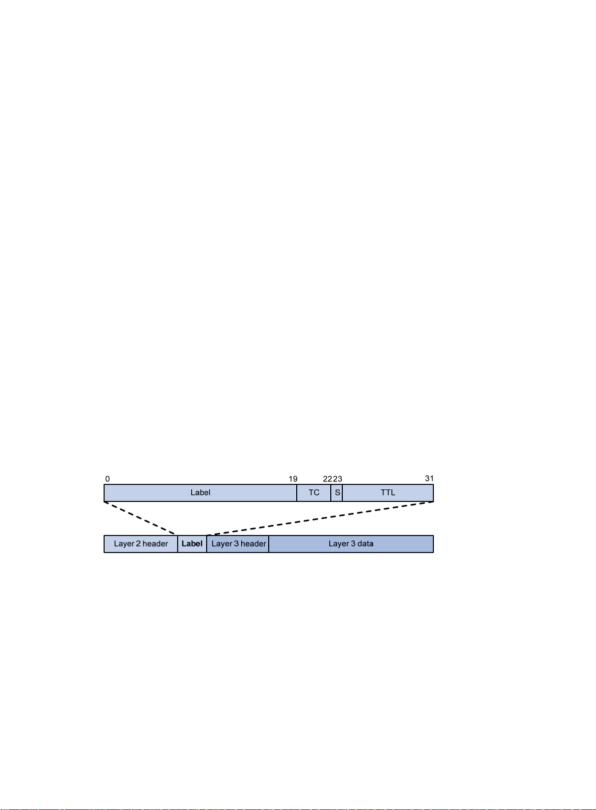
Figure 1 Format of a label
A label is encapsulated betwee n the Layer 2 heade r and Layer 3 header of a packet. It is four bytes
long and consists of the following fields:
• Label—20-bit label value.
• TC—3-bit traffic class, used for QoS. It is also called Exp.
• S—1-bit bottom of stack flag. A label stack can contain multiple labels. The label nearest to the
Layer 2 header is called the top label, and the label nearest to the Layer 3 header is called the
bottom label. The S field is set to 1 if the label is the bottom label and set to 0 if not.
• TTL—8-bit time to live field used for MPLS loop prevention.
LSR
A router that performs MPLS forwarding is a label switching router (LSR).
1
Page 12
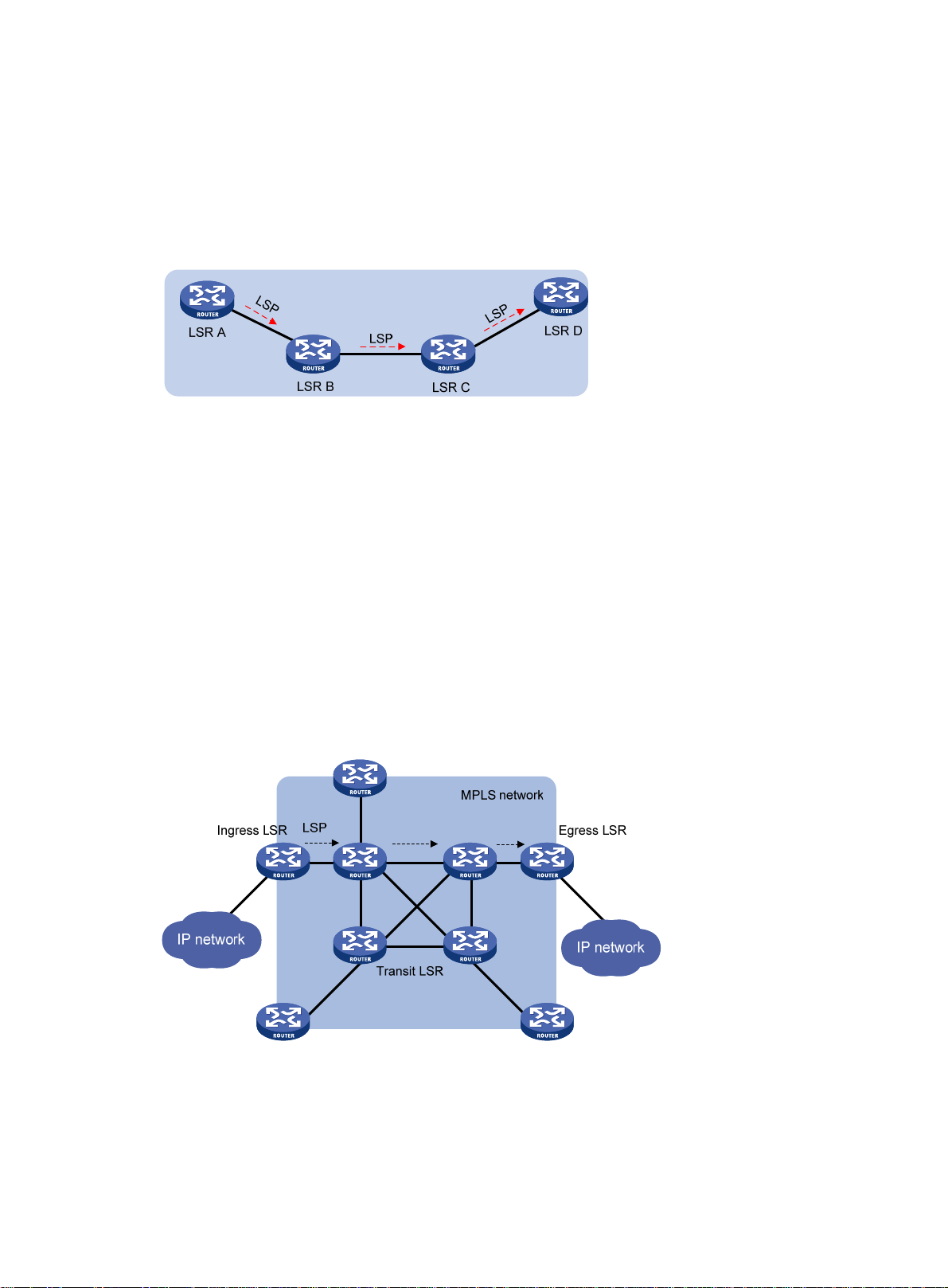
LSP
LFIB
A label switched path (LSP) is the path along which packets of an FEC travel through an MPLS
network.
An LSP is a unidirectional packet forwarding path. Two neighboring LSRs are called the upstream
LSR and downstream LSR along the direction of an LSP. As shown in Figure 2, LSR B
downstream LSR of LSR A, and LSR A is the upstream LSR of LSR B.
Figure 2 Label switched path
The Label Forwarding Information Base (LFIB) on an MPLS network functions like the Forwarding
Information Base (FIB) on an IP network. When an LSR receives a labeled packet, it searches the
LFIB to obtain information for forwarding the packet. The information includes the label operation
type, the outgoing label value, and the next hop.
is the
Control plane and forwarding plane
An MPLS node consists of a control plane and a forwarding plane.
• Control plane—Assigns labels, distributes FEC-label mappings to neighbor LSRs, creates the
LFIB, and establishes and removes LSPs.
• Forwarding plane—Forwards packets according to the LFIB.
MPLS network architecture
Figure 3 MPLS network architecture
An MPLS network has the following types of LSRs:
• Ingress LSR—Ingress LSR of packets. It labels packets entering into the MPLS network.
• Transit LSR—Intermediate LSRs in the MPLS network. The transit LSRs on an LSP forward
packets to the egress LSR according to labels.
2
Page 13
• Egress LSR—Egress LSR of packets. It removes labels from packets and forwards the
packets to their destination networks.
LSP establishment
LSPs include static and dynamic LSPs.
• Static LSP—To establish a static LSP, you must configure an LFIB entry on each LSR along the
LSP. Establishing static LSPs consumes fewer resources than establishing dynamic LSPs, but
static LSPs cannot automatically adapt to network topology changes. Therefore, static LSPs
are suitable for small-scale networks with simple, stable topologies.
• Dynamic LSP—Established by a label distribution protocol (also called an MPLS signaling
protocol). A label distribution protocol classifies FECs, distributes FEC-label mappings, and
establishes and maintains LSPs. Label distribution protocols include protocols designed
specifically for label distribution, such as the Label Distribution Protocol (LDP), and protocols
extended to support label distribution, such as MP-BGP and RSVP-TE.
In this document, the term "label distribution protocols" refers to all protocols for label distribution.
The term "LDP" refers to the RFC 5036 LDP.
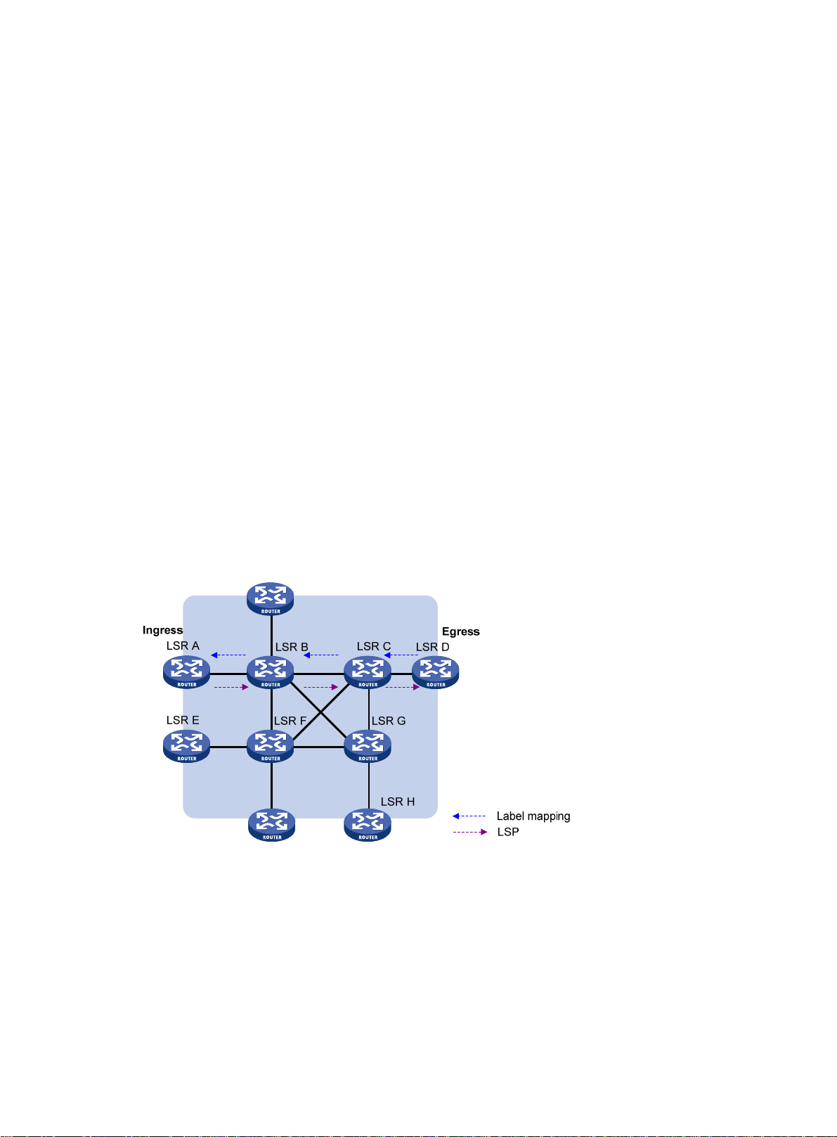
A dynamic LSP is established in the following steps:
1. A downstream LSR classifies FECs according to destination addresses.
2. The downstream LSR assigns a label for each FEC, and distributes the FEC-label binding to its
upstream LSR.
3. The upstream LSR establishes an LFIB entry for the FEC according to the binding inform ation.
After all LSRs along the LSP establish an LFIB entry for the FEC, a dynamic LSP is established for
the packets of this FEC.
Figure 4 Dynamic LSP establishment
3
Page 14
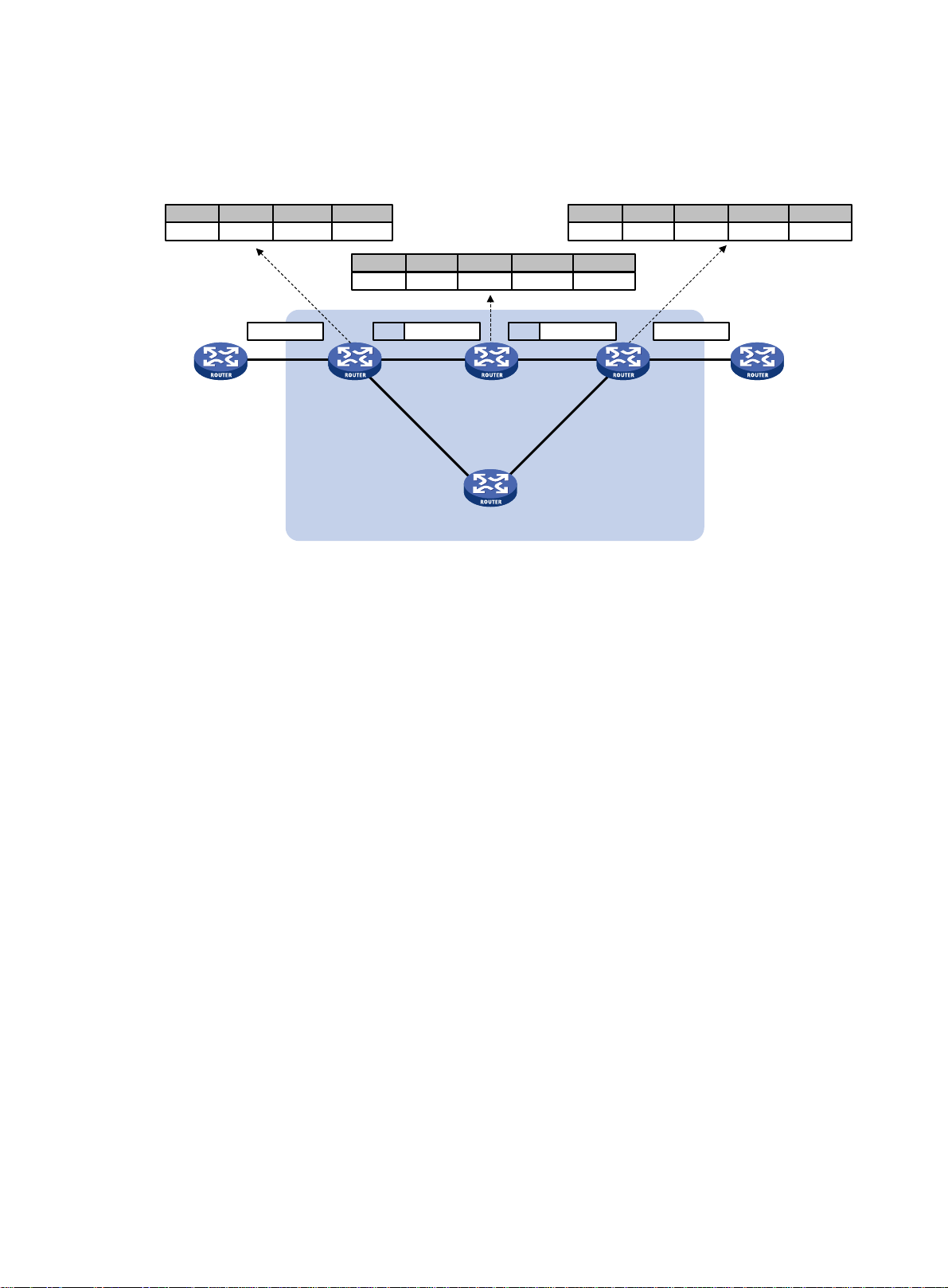
MPLS forwarding
Figure 5 MPLS forwarding
10.1.0.0
Router A
FIB table
NexthopDest Out intOut label
Router C
IP:10.1.1.1
GE2/0/1 GE2/0/2
GE2/0/240
In label
Router B
Ingress
40
Oper
Swap
GE2/0/1
LFIB table
Out label
50
Router C
Router F
Nexthop
Router D
GE2/0/2
In label
Out int
GE2/0/2
GE2/0/1
Oper
50
Router D
Egress
MPLS network
Pop
Out label
IP:10.1.1.140 IP:10.1.1.1 50 IP:10.1.1.1
GE2/0/2
LFIB table
Nexthop
--
Router E
Router E
Out int
GE2/0/2
As shown in Figure 5, a packet is forwarded over the MPLS network as follows:
1. Router B (the ingress LSR) receives a packet with no label. Then, it performs the following
operations:
a. Identifies the FIB entry that matches the destination address of the packet.
b. Adds the outgoing la bel (40, in this example) to the packet.
c. Forwards the labeled packet out of the interface GigabitEthernet 2/0/2 to the next hop LSR
Router C.
2. When receiving the labeled packet, Router C processes the packet as follows:
a. Identifies the LFIB entry that has an incoming label of 40.
b. Uses the outgoing label 5 0 of the entry to replace label 40 in the packet.
c. Forwards the labeled packet out of the outgoing interface GigabitEthernet 2/0/2 to the next
hop LSR Router D.
3. When receiving the labeled packet, Router D (the egress LSR) processes the packet as follows:
a. Identifies the LFIB entry that has an incoming label of 50.
b. Removes the label from th e packet.
c. Forwards the packet out of the outgoing interface GigabitEthernet 2/0/2 to the next hop LSR
Router E.
If the LFIB entry records no outgoing interface or next hop information, Router D performs the
following operations:
a. Identifies the FIB entry by the IP header.
b. Forwards the packet according to the FIB entry.
PHP
An egress node must perform two forwarding table lookups to forward a packet:
• Two LFIB lookup s (if the packet has more than one label).
4
Page 15

• One LFIB lookup and one FIB lookup (if the packet has only one label).
The penultimate hop popping (PHP) feature can pop the label at the penultimate node, so the egress
node only performs one table lookup.
A PHP-capable egress node sends the penultimate node an implicit null label of 3. This label never
appears in the label stack of packets. If an incoming packet matches an LFIB entry containing the
implicit null label, the penultimate node pops the top label and forwards the packet to the egress
node. The egress node directly forwards the packet.
Sometimes, the egress node must use the TC field in the label to perform QoS. To keep the TC
information, you can configure the egress node to send the penultimate node an explicit null label of
0. If an incoming packet matches an LFIB entry containing the explicit null label, the penultimate hop
replaces the top label value with value 0, and forwards the packet to the egress node. The egress
node gets the TC information, pops the label of the packet, and forwards the packet.
Protocols and standards
• RFC 3031, Multiprotocol Label Switching Architecture
• RFC 3032, MPLS Label Stack Encoding
• RFC 5462, Multiprotocol Label Switching (MPLS) Label Stack Entry: "EXP" Field Renamed to
"T raffic Class" Field
Compatibility information
Commands and descriptions for centralized devices apply to the followin g routers:
• MSR1002-4/1003-8S.
• MSR2003.
• MSR2004-24/2004-48.
• MSR3012/3024/3044/3064.
Commands and descriptions for distributed devices apply to MSR4060 and MSR4080 routers.
MPLS configuration task list
Tasks at a glance
(Required.) Enabling MPLS
(Optional.) Setting MPLS MTU
(Optional.) Specifying the label type advertised by the egress
(Optional.) Configuring TTL propagation
(Optional.) Enabling sending of MPLS TTL-expired messages
(Optional.) Enabling MPLS forwarding statistics
(Optional.) Enabling split horizon for MPLS forwarding
(Optional.) Enabling SNMP notifications for MPLS
5
Page 16

Enabling MPLS
Before you enable MPLS, perform the following tasks:
• Configure link layer protocols to ensure connectivity at the link layer.
• Configure IP addresses for interfaces to ensure IP conne ctivity between neighboring nodes.
• Configure static routes or an IGP protocol to ensure IP connectivity among LSRs.
To enable MPLS:
Step Command Remarks
1. Enter system view.
2. Configure an LSR ID for the
local node.
3. Enter the view of the interface
that needs to perform MPLS
forwarding.
system-view
mpls lsr-id
interface
interface-number
lsr-id
interface-type
N/A
By default, no LSR ID is configured.
An LSR ID must be unique in an
MPLS network and in IP address
format. As a best practice, use the
IP address of a loopback interface
as an LSR ID.
N/A
4. Enable MPLS on the interface.
Setting MPLS MTU
MPLS adds the label stack between the link layer header and network layer header of each packet.
T o ma ke sure the size of MPLS labeled packets i s smaller than the MTU of an interface, configure a n
MPLS MTU on the interface.
MPLS compares each MPLS packet against the interface MPLS MTU. When the packet exceeds the
MPLS MTU:
• If fragmentation is allowed, MPLS performs the following operations:
a. Removes the label stack from the packet.
b. Fragments the IP packet. The length of a fragment is the MPLS MTU minus the length of the
label stack.
c. Adds the label stack to each fragment, and forwards the fragments.
• If fragmentation is not allowed, the LSR drops the packet.
To set an MPLS MTU for an interface:
Step Command Remarks
1. Enter system view.
mpls enable
system-view
By default, MPLS is disabled on the
interface.
N/A
2. Enter interface view.
3. Set an MPLS MTU for the
interface.
interface
interface-number
mpls mtu
interface-type
value
The following applies when an interface handles MPLS packets:
6
N/A
By default, no MPLS MTU is set
on an interface.
Page 17

• MPLS packets carrying L2VPN or IPv6 packets are always forwarded by an interface, even if
the length of the MPLS packets exceeds the MPLS MTU of the interface. Whether the
forwarding can succeed depends on the actual forwarding capacity of the interface.
• If the MPLS MTU of an interface is greater than the MTU of the interface, data forwarding might
fail on the interface.
• If you do not configure the MPLS MTU of an interface, fragmentation of MPLS packets is based
on the MTU of the interface without considering MPLS labels. An MPLS fragment might be
larger than the interface MTU and be dropped.
Specifying the label type advertised by the egress
In an MPLS network, an egress can advertise the following types of labels:
• Implicit null label with a value of 3.
• Explicit null label with a value of 0.
• Non-null label.
For LSPs established by a label distribution protocol, the label advertised by the egress determines
how the penultimate hop processes a labeled packet.
• If the egress advertises an implicit null label, the penultimate hop directly pops the top label of a
matching packet.
• If the egress advertises an explicit null label, the penultimate hop swaps the top label value of a
matching packet with the explicit null label.
• If the egress advertises a non-null label, the penultimate hop swaps the top label of a matching
packet with the label assigned by the egress.
Configuration guidelines
As a best practice, configure the egress to advertise an implicit null label to the penultimate hop if the
penultimate hop supports PHP. If you want to simplify packet forwarding on the egress but keep
labels to determine QoS policies, configure the egress to advertise an explicit null label to the
penultimate hop. Use non-null labels only in particular scenarios. For example, when OAM is
configured on the egress, the egress can get the OAM function entity status only through non-null
labels.
As a penultimate hop, the device accepts the implicit null label, explicit null label, or normal label
advertised by the egress device.
For LDP LSPs, the mpls label advertise command triggers LDP to delete the LSPs established
before the command is executed and re-establishes new LSPs.
For BGP LSPs, the mpls label advertise command takes effect only on the BGP LSPs estab lished
after the command is executed. To apply the new setting to BGP LSPs established before the
command is executed, delete the routes corresponding to the BGP LSPs, and then redistribute the
routes.
Configuration procedure
To specify the type of label that the egress node will advertise to the penultimate hop:
Step Command Remarks
1. Enter system view.
2. Specify the label type
advertised by the egress to
the penultimate hop.
system-view
mpls label advertise
explicit-null
{
non-null
}
implicit-null
|
N/A
|
By default, an egress advertises
an implicit null label to the
penultimate hop.
7
Page 18

Configuring TTL propagation
When TTL propagation is enabl ed, the ingress node copi es the TTL value of an IP packet to the TTL
field of the label. Each LSR on the LSP decreases the label TTL value by 1. The LSR that pops the
label copies the remaining label TTL value back to the IP TTL of the packet. The IP TTL value can
reflect how many hops the packet has traversed in the MPLS network. The IP tracert facility can
show the real path along which the packet has traveled.
Figure 6 TTL propagation
When TTL propagation is disabl ed, the ingress node sets the label TTL to 255. Each LSR on the LSP
decreases the label TTL value by 1. The LSR that pops the label does not change the IP TTL value
when popping the label. Therefore, the MPLS backbone nodes are invisible to user networks, and
the IP tracert facility cannot show the real path in the MPLS network.
Figure 7 Without TTL propagation
Follow these guidelines when you configure TTL propagation:
• As a best practice, set the same TTL processing mode on all LSRs of an LSP.
• To enable TTL propagation for a VPN, you must enable it on all PE devices in the VPN. Then,
you can get the same traceroute result (hop count) from those PEs.
To enable TTL propagation:
Step Command Remarks
1. Enter system view.
system-view
N/A
8
Page 19

Step Command Remarks
By default, TTL propagation is enabled only
for public-network packets.
2. Enable TTL
propagation.
mpls ttl propagate
vpn
}
public
{
|
This command affects only the propagation
between IP TTL and label TTL. Within an
MPLS network, TTL is always copied
between the labels of an MPLS packet.
Enabling sending of MPLS TTL-expired messages
This feature enables an LSR to generate an ICMP TTL-expired message upon receiving an MPLS
packet with a TTL of 1. If the MPLS packet has only one label, the LSR sends the ICMP TTL-expired
message back to the source through IP routing. If the MPLS packet has multiple labels, the LSR
sends it along the LSP to the egress, which then sends the message back to the sou rce.
To enable sending of MPLS TTL-expired messages:
Step Command Remarks
1. Enter system view.
2. Enable sending of MPLS
TTL-expired messages.
system-view
mpls ttl expiration enable
N/A
By default, this function is
enabled.
Enabling MPLS forwarding statistics
Enabling FTN forwarding statistics
FEC-to-NHLFE map (FTN) entries are FIB entries that contain outgoing labels used for FTN
forwarding. When an LSR receives an unlabeled packet, it searches for the corresponding FTN entry
based on the destination IP address. If a match is found, the LSR adds the outgoing label i n the FTN
entry to the packet and forwards the labeled packet.
To enable FTN forwarding statistics:
Step Command Remarks
1. Enter system view.
2. Enter RIB view.
3. Create a RIB IPv4 address
family and enter RIB IPv4
address family view.
4. Enable the device to
maintain FTN entries in the
RIB.
5. Enable FTN forwarding
statistics for a destination
network.
system-view
rib
address-family ipv4
ftn enable
mpls-forwarding statistics
prefix-list
prefix-list-name
N/A
N/A
By default, no RIB IPv4
address family is created.
By default, the device does not
maintain FTN entries in the
RIB.
By default, FTN forwarding
statistics is disabled for all
destination networks.
9
Page 20

Enabling MPLS label forwarding statistics for LSPs
MPLS label forwarding for LSPs forwards a labeled packet based on its incoming label.
Perform this task to enable MPLS label forwarding statistics for LSPs and MPLS statistics reading.
Then, you can use the display mpls lsp verbose command to view MPLS label statistics.
To enable MPLS label forwarding statistics:
Step Command Remarks
1. Enter system view.
system-view
N/A
2. Enable MPLS label
forwarding statistics for the
specified LSPs.
3. Enable MPLS label
statistics reading, and set
the reading interval.
mpls statistics
vpn-instance-name ] {
ipv4-destination mask-length |
ipv6-destination prefix-length } |
static
mpls statistics interval
te
|
all
vpn-instance
{
| [
ipv4
ipv6
ingress-lsr-id tunnel-id }
interval
By default, MPLS label
forwarding statistics are disabled
for all LSPs.
By default, MPLS label statistics
reading is disabled.
Enabling MPLS label forwarding statistics for a VPN instance
MPLS label forwarding for a VPN instance performs the following operations:
• Forwards a labeled packet for the VPN instance based on its incoming label.
• Adds a label to an unlabeled packet received by the VPN instance and forwards the labeled
packet.
Perform this task to enable MPLS label forwarding statistics for a VPN instance and MPLS st atistics
reading. Then, you can use the display ip vpn-instance mpls statistics command to view MPLS
label statistics.
To enable MPLS label forwarding statistics:
Step Command Remarks
1. Enter system view.
2. Enter VPN instance view.
3. Enable MPLS label
forwarding statistics for the
VPN instance.
4. Enable MPLS label
statistics reading, and set
the reading interval.
system-view
ip vpn-instance
mpls statistics enable
mpls statistics interval
vpn-instance-name N/A
interval
N/A
By default, MPLS label
forwarding statistics are disabled
for all VPN instances.
By default, MPLS label statistics
reading is disabled.
Enabling split horizon for MPLS forwarding
This feature prevents MPLS packets received from an interface from being forwarded back to that
interface to provide loop-free forwarding.
To enable split horizon for MPLS forwarding:
Step Command Remarks
1. Enter system view.
system-view
10
N/A
Page 21

Step Command Remarks
2. Enable split horizon for
MPLS forwarding.
mpls forwarding split-horizon
By default, split horizon is
disabled for MPLS forwarding.
Enabling SNMP notifications for MPLS
This feature enables MPLS to generate SNMP notifications. The generated SNMP notifications are
sent to the SNMP module.
For more information about SNMP notifications, see Network Management and Monitoring
Configuration Guide.
To enable SNMP notifications for MPLS:
Step Command Remarks
1. Enter system view.
2. Enable SNMP
notifications for MPLS.
system-view
snmp-agent trap enable mpls
N/A
By default, SNMP notifications for
MPLS are enabled.
Displaying and maintaining MPLS
Execute display commands in any view and reset commands in user view.
Task Command
Display MPLS interface information.
Display usage information for MPLS
labels.
Display LSP information.
Display MPLS Nexthop Information
Base (NIB) information.
Display usage information for NIDs.
Display LSP statistics.
Display MPLS summary information.
Display MPLS label forwarding statistics
for VPN instances.
Display ILM entries (centralized devices
in standalone mode).
display mpls interface
display mpls label
display mpls lsp
outgoing-interface
bgp
ldp
{
vpn-instance
[
ipv6
display mpls nib
display mpls nid
display mpls lsp statistics
display mpls summary
display ip vpn-instance mpls statistics
vpn-instance-name ]
display mpls forwarding ilm
local
|
|
vpn-instance-name ] [ ipv4-dest mask-length |
[ ipv6-dest prefix-length ] ] [
[ interface-type interface-number ]
{ label-value1 [
egress
[
|
[ nib-id ]
[ nid-value1 [ to nid-value2 ] ]
|
interface-type interface-number |
rsvp-te
in-label
static
|
[ label ]
to
label-value2 ] |
label-value |
static-cr
|
verbose
ingress
transit
} |
]
instance-name
[
all }
|
protocol
]
Display ILM entries (distributed devices
in standalone mode/centralized devices
in IRF mode).
Display ILM entries (distributed devices
in IRF mode).
Display NHLFE entries (centralized
display mpls forwarding ilm
display mpls forwarding ilm
slot
slot-number ]
display mpls forwarding nhlfe
11
[ label ] [
[ label ] [
[ nid ]
slot
slot-number ]
chassis
chassis-number
Page 22

Task Command
devices in standalone mode).
Display NHLFE entries (distributed
devices in standalone mode/centralized
devices in IRF mode).
display mpls forwarding nhlfe
[ nid ] [
slot
slot-number ]
Display NHLFE entries (distributed
devices in IRF mode).
Clear MPLS forwarding statistics for the
specified LSPs.
Clear MPLS forwarding statistics for
VPN instances.
display mpls forwarding nhlfe
slot
slot-number ]
reset mpls statistics
ipv4
{
ipv4-destination mask-length |
prefix-length } |
all
{
static
| te ingress-lsr-id tunnel-id }
[ nid ] [
vpn-instance
| [
reset ip vpn-instance mpls statistics
vpn-instance-name ]
chassis
chassis-number
vpn-instance-name ]
ipv6
ipv6-destination
instance-name
[
12
Page 23

Configuring a static LSP
Overview
A static label switched path (LSP) is established by manually specifying the incoming label and
outgoing label on each node (ingress, transit, or egress node) of the forwarding path.
Static LSPs consume fewer resources, but they cannot automatically adapt to network topology
changes. Therefore, static LSPs are suitable for small and stable n etworks with simple topologies.
Follow these guidelines to establish a static LSP:
• The ingress node performs the following operations:
a. Determines an FEC for a packet according to the destination address.
b. Adds the label for that FEC into the packet.
c. Forwards the packet to the next hop or out of the outgoing interface.
Therefore, on the ingress node, you must specify the outgoing label for the destination address
(the FEC) and the next hop or the outgoing interface.
• A transit node swaps the label carried in a received p acket with a label, and forwards the packet
to the next hop or out of the outgoing interface. Therefore, on each transit node, you must
specify the incoming label, the outgoing label, and the next hop or the outgoing interface.
• If PHP is not configured, an egress node pops the incoming label of a packet, and performs
label forwarding according to the inner label or IP forwarding. Therefore, on the e gre ss node,
you only need to specify the incoming label.
• The outgoing label specified on an LSR must be the same as the incoming label specified on
the directly connected downstream LSR.
Configuration prerequisites
Before you configure a static LSP, perform the following tasks:
1. Identify the ingress node, transit nodes, and egress node of the LSP.
2. Enable MPLS on all interfaces that participate in MPLS forwarding. For more information, see
"Configuring basic MPLS."
3. Make
sure the ingress node has a route to the destination address of the LSP. This is not
required on transit and egress nodes.
Configuration procedure
To configure a static LSP:
Step Command Remarks
1. Enter system view.
2. Configure the ingress
node of the static LSP.
3. Configure the transit
node of the static LSP.
system-view
static-lsp ingress
destination
mask-length } {
outgoing-interface
interface-number }
static-lsp transit
in-label {
dest-addr { mask |
nexthop
lsp-name
nexthop
lsp-name
interface-type
out-label
next-hop-addr |
next-hop-addr |
out-label
in-label
N/A
If you specify a next hop for the
static LSP, make sure the ingress
node has an active route to the
specified next hop address.
If you specify a next hop for the
static LSP, make sure the transit
13
Page 24
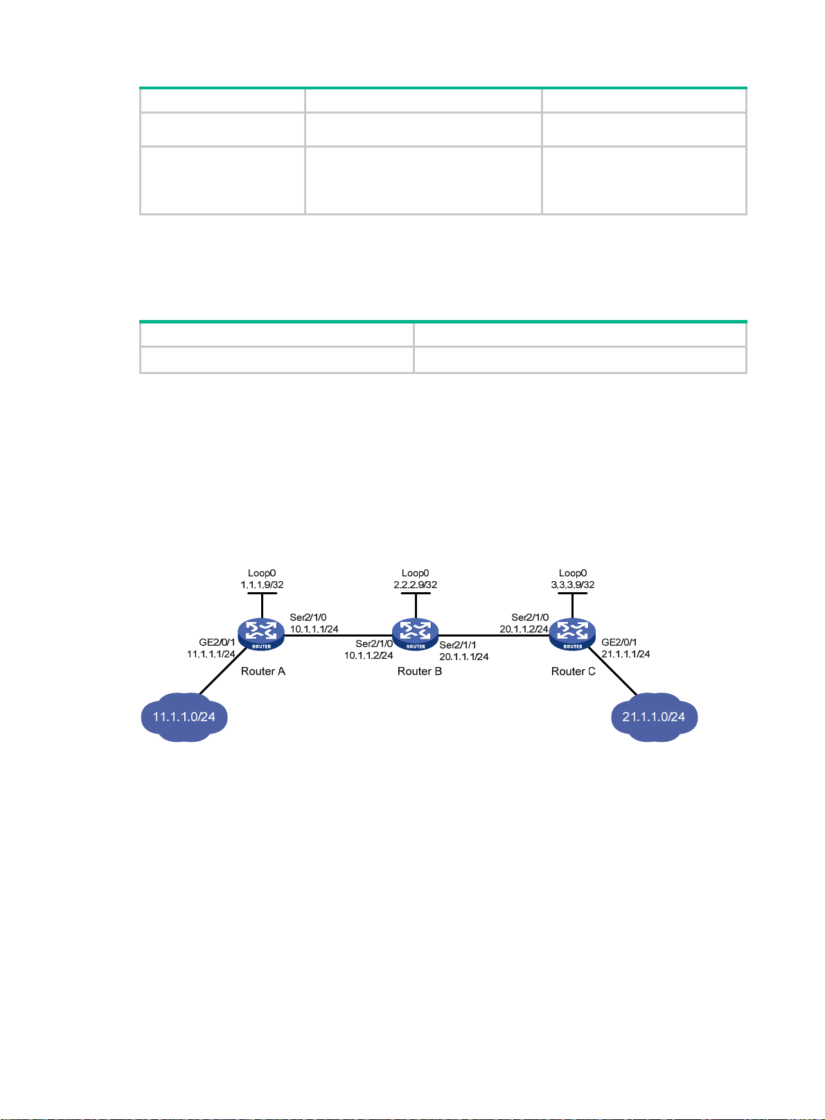
Step Command Remarks
outgoing-interface
interface-number }
interface-type
out-label
out-label
node has an active route to the
specified next hop address.
4. Configure the egress
node of the static LSP.
static-lsp egress
in-label
lsp-name
in-label
Displaying static LSPs
Execute display commands in any view .
Task Command
Display static LSP information.
display mpls static-lsp
Static LSP configuration example
Network requirements
Router A, Router B, and Router C all support MPLS.
Establish static LSPs between Router A and Router C, so that subnets 11.1.1.0/24 and 21.1.1.0/24
can access each other over MPLS.
Figure 8 Network diagram
You do not need to configure this
command if the outgoing label
configured on the penultimate hop
of the static LSP is 0 or 3.
lsp-name
[
lsp-name ]
Configuration restrictions and guidelines
• For an LSP, the outgoing label specified on an LSR must be identical with the incoming label
specified on the downstream LSR.
• LSPs are unidirectional. You must configure an LSP for each direction of the data forwarding
path.
• A route to the destination address of the LSP must be available on the ingress and egress
nodes, but it is not needed on transit nodes. Therefore, you do not need to configure a routing
protocol to ensure IP connectivity among all routers.
Configuration procedure
1. Configure IP addresses for all interfaces, including the loopback interfaces, as shown in Figure
8. (Details not shown.)
2. Configure a static route to the destination address of each LSP:
# On Router A, configure a static route to network 21.1.1.0/24.
14
Page 25

<RouterA> system-view
[RouterA] ip route-static 21.1.1.0 24 10.1.1.2
# On Router C, configure a static route to network 11.1.1.0/24.
<RouterC> system-view
[RouterC] ip route-static 11.1.1.0 255.255.255.0 20.1.1.1
3. Configure basic MPLS on the routers:
# Configure Router A.
[RouterA] mpls lsr-id 1.1.1.9
[RouterA] interface serial 2/1/0
[RouterA-Serial2/1/0] mpls enable
[RouterA-Serial2/1/0] quit
# Configure Router B.
[RouterB] mpls lsr-id 2.2.2.9
[RouterB] interface serial 2/1/0
[RouterB-Serial2/1/0] mpls enable
[RouterB-Serial2/1/0] quit
[RouterB] interface serial 2/1/1
[RouterB-Serial2/1/1] mpls enable
[RouterB-Serial2/1/1] quit
# Configure Router C.
[RouterC] mpls lsr-id 3.3.3.9
[RouterC] interface serial 2/1/0
[RouterC-Serial2/1/0] mpls enable
[RouterC-Serial2/1/0] quit
4. Configure a static LSP from Router A to Router C:
# Configure the LSP ingress node, Router A.
[RouterA] static-lsp ingress AtoC destination 21.1.1.0 24 nexthop 10.1.1.2 out-label
30
# Configure the LSP transit node, Router B.
[RouterB] static-lsp transit AtoC in-label 30 nexthop 20.1.1.2 out-label 50
# Configure the LSP egress node, Router C.
[RouterC] static-lsp egress AtoC in-label 50
5. Create a static LSP from Router C to Router A:
# Configure the LSP ingress node, Router C.
[RouterC] static-lsp ingress CtoA destination 11.1.1.0 24 nexthop 20.1.1.1 out-label
40
# Configure the LSP transit node, Router B.
[RouterB] static-lsp transit CtoA in-label 40 nexthop 10.1.1.1 out-label 70
# Configure the LSP egress node, Router A.
[RouterA] static-lsp egress CtoA in-label 70
Verifying the configuration
# Display static LSP information on routers, for example, on Router A.
[RouterA] display mpls static-lsp
Total: 2
Name FEC In/Out Label Nexthop/Out Interface State
AtoC 21.1.1.0/24 NULL/30 10.1.1.2 Up
CtoA -/- 70/NULL - Up
15
Page 26

# Test the connectivity of the LSP from Router A to Router C.
[RouterA] ping mpls -a 11.1.1.1 ipv4 21.1.1.0 24
MPLS Ping FEC: 21.1.1.0/24 : 100 data bytes
100 bytes from 20.1.1.2: Sequence=1 time=4 ms
100 bytes from 20.1.1.2: Sequence=2 time=1 ms
100 bytes from 20.1.1.2: Sequence=3 time=1 ms
100 bytes from 20.1.1.2: Sequence=4 time=1 ms
100 bytes from 20.1.1.2: Sequence=5 time=1 ms
--- FEC: 21.1.1.0/24 ping statistics ---
5 packets transmitted, 5 packets received, 0.0% packet loss
round-trip min/avg/max = 1/1/4 ms
# Test the connectivity of the LSP from Router C to Router A.
[RouterC] ping mpls -a 21.1.1.1 ipv4 11.1.1.0 24
MPLS Ping FEC: 11.1.1.0/24 : 100 data bytes
100 bytes from 10.1.1.1: Sequence=1 time=5 ms
100 bytes from 10.1.1.1: Sequence=2 time=1 ms
100 bytes from 10.1.1.1: Sequence=3 time=1 ms
100 bytes from 10.1.1.1: Sequence=4 time=1 ms
100 bytes from 10.1.1.1: Sequence=5 time=1 ms
--- FEC: 11.1.1.0/24 ping statistics ---
5 packets transmitted, 5 packets received, 0.0% packet loss
round-trip min/avg/max = 1/1/5 ms
16
Page 27

Configuring LDP
Overview
The Label Distribution Protocol (LDP) dynamically distributes FEC-label mapping information
between LSRs to establish LSPs.
Terminology
LDP session
Two LSRs establish a TCP-based LDP session to exchange FEC-label mappings.
LDP peer
Two LSRs that use L DP to exchange FEC-label mappings are LSR peers.
Label spaces and LDP identifiers
Label spaces include the following types:
• Per-interface label space—Each interface uses a single, independent label space. Different
interfaces can use the same label values.
• Per-platform label space—Each LSR uses a single label space. The device only supports the
per-platform label space.
A six-byte LDP Identifier (LDP ID) identifies a label space on an LSR. It is in the format of <LSR
ID>:<label space number>, where:
• The LSR ID takes four bytes to identity the LSR.
• The label space number takes two bytes to identify a label space within the LSR.
A label space number of 0 indicates that the label spa ce is a per-platform label sp ace. A label space
number other than 0 indicates a per-interface label space.
LDP uses the same LDP ID format on IPv4 and IPv6 networks. An LDP ID must be globally unique.
FECs and FEC-label mappings
MPLS groups packets with the same characteristics (such as the same destination or service class)
into a class, called an FEC. The packets of the same FEC are handled in the same way on an MPLS
network.
LDP can classify FECs by destination IP address and by PW. This document describes FEC
classification by destination IP address. For information about FEC classification by PW, see
"Configuring MPLS L2VPN" and "Configuring VPLS."
An LSR assig
its peers in a Label Mapping message.
ns a label for an FEC and advertises the FEC-label mapping, or FEC-label binding, to
LDP messages
LDP mainly uses the following types of messages:
• Discovery messages—Declare and maintain the presence of LS Rs, such as Hello me ssages.
• Session messages—Establish, maintain, and terminate sessions between LDP peers, such
as Initialization messages used for parameter negotiation and Keepalive messages used to
maintain sessions.
17
Page 28

• Advertisement messages—Create, alter , and remove FEC-label mappings, such as Label
Mapping messages used to advertise FEC-label mappings.
• Notification messages—Provide advisory information and notify errors, such as Notification
messages.
LDP uses UDP to transport discovery messages for efficiency, and uses TCP to transport session,
advertisement, and notification messages for reliability.
LDP operation
LDP can operate on an IPv4 or IPv6 network, or a network where IPv4 coexists with IPv6. LDP
operates similarly on IPv4 and IPv6 networks.
LDP operates in the following phases:
Discovering and maintaining LDP peers
LDP discovers peers in the following ways:
• Basic Discovery—Discovers directly connected LSRs.
{ On an IPv4 network, an LSR sends IPv4 Link Hello messages to multicast address
224.0.0.2. All directly connected LSRs can discover the LSR and establish an IPv4 Link
Hello adjacency.
{ On an IPv6 network, an LSR sends IPv6 Link Hello messages to FF02:0:0:0:0:0:0:2. All
directly connected LSRs can discover the LSR and establish an IPv6 Link Hello adjacency.
{ On a network where IPv4 and IPv6 coexist, an LSR sends both IPv4 and IPv6 Link Hello
messages to each directly connected LSR and keeps both the IPv4 and IPv6 Link Hello
adjacencies with a neighbor.
• Extended Discovery—Sends LDP IPv4 Targeted Hello messages to an IPv4 address or LDP
IPv6 Targeted Hello messages to an IPv6 address. The destination LSR can discover the LSR
and establish a hello adjacency. This mechanism is typically used i n LDP session protection,
LDP over MPLS TE, MPLS L2VPN, and VPLS. For more information about MPLS L2VPN and
VPLS, see "Configuring MPLS L2VPN," and "Configuring VPLS."
can establish two hello adjacencies with a directly connected neighbor through both discovery
LDP
mechanisms. It sends Hello messages at the hello interval to maintain a hello adjacency. If LDP
receives no Hello message from a hello adjacency before the hello hold timer expires, it removes the
hello adjacency.
Establishing and maintaining LDP sessions
LDP establishes a session to a peer in the following steps:
1. Establishes a TCP connection with the neighbor.
On a network where IPv4 and IPv6 coexist, LDP establishes an IPv6 TCP connection. If LDP
fails to establish the IPv6 TCP connection, LDP tries to establish an IPv4 TCP connection.
2. Negotiates session parameters such as LDP version, label distribution method, and Keepalive
timer, and establishes an LDP session to the neighbor if the negotiation succeeds.
After a session is established, LDP sends LDP PDUs (an LDP PDU carries one or more LDP
messages) to maintain the session. If no information is exchanged between the LDP peers within th e
Keepalive interval, LDP sends Keepalive messages at the Keepali ve interval to maintain the session.
If LDP receives no LDP PDU from a neighbor before the keep alive hold timer expires, or the last hello
adjacency with the neighbor is removed, LDP terminates the session.
LDP can also send a Shutdown message to a neighbor to terminate the LDP session.
An LSR can establish only one LDP session to a neighbor. The session can be used to exchange
IPv4 and IPv6 FEC-label mappings at the same time.
18
Page 29
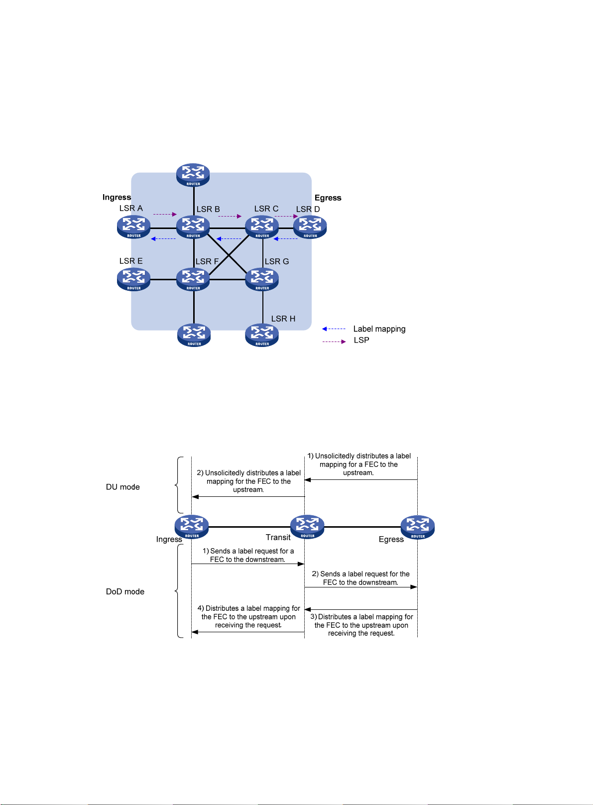
Establishing LSPs
LDP classifies FECs according to destination IP addresses in IP routing entries, creates FEC-label
mappings, and advertises the mappings to LDP peers through LDP sessions. After an LDP peer
receives an FEC-label mapping, it uses the received label and the label locally assigne d to that FEC
to create an LFIB entry for that FEC. When all LSRs (from the Ingress to the Egress) establish an
LFIB entry for the FEC, an LSP is established exclusively for the FEC.
Figure 9 Dynamically establishing an LSP
Label distribution and control
Label advertisement modes
Figure 10 Label advertisement modes
LDP advertises label-FEC mappings in one of the following way s:
• Downstream Unsolicited (DU) mode—Distributes FEC-label mappings to the upstre am LSR,
without waiting for label requests. The device supports only the DU mode.
19
Page 30

A
• Downstream on Demand (DoD) mode—Sends a label request for an FEC to the downstream
LSR. After receiving the label reque st, the downstre am LSR distrib utes the FEC-label mapping
for that FEC to the upstream LSR.
NOTE:
pair of upstream and downstream LSRs must use the same label advertisement mode. Otherwise,
the LSP cannot be established.
Label distribution control
LDP controls label distribution in one of the following ways:
• Independent label distribution—Distributes an FEC-label mapping to an upstream LSR at
any time. An LSR might distribute a mapping for an FEC to its upstream LSR before it receives
a label mapping for that FEC from its downstream LSR. As shown in Figure 11, in DU mode,
each LSR di
label-switch the FEC. The LSRs do not need to wait for a label mapping for the FEC from its
downstream LSR. In DoD mode, an LSR distributes a label mapping for an FEC to its upstream
LSR after it receives a label request for the FEC. The LSR does not need to wait for a label
mapping for the FEC from its downstream LSR.
Figure 11 Independent label distribution control mode
stributes a label mapping for an FEC to its upstream LSR whenever it is ready to
• Ordered label distribution—Distributes a label mapping for an FEC to its upstream LSR only
after it receives a label mapping for that FEC from its downstream LSR unless the local node is
the egress node of the FEC. As shown in Figure 10, in DU mo
de, an LSR distributes a label
mapping for an FEC to its upstream LSR only if it receiv es a label mappin g for the FEC from its
downstream LSR. In DoD mode, when an LSR (Transit) receives a label request for an FEC
from its upstream LSR (Ingress), it continues to send a label request for the FEC to its
downstream LSR (Egress). After the transit LSR receives a label m apping for the FEC from the
egress LSR, it distributes a label mapping for the FEC to the ingress LSR.
Label retention mode
The label retention mode specifies whether an LSR maintains a label mapping for an FEC learned
from a neighbor that is not its next hop.
• Liberal label retention—Retains a received label mapping for an FEC regardless of whether
the advertising LSR is the next hop of the FEC. This mechanism allows for quicke r adaptation to
topology changes, but it wastes system resources because LDP has to keep us eless labels.
The device only supports liberal label retention.
20
Page 31

• Conservative label retention—Retains a received label mapping for an FEC only when the
LDP GR
LDP Graceful Restart (GR) preserves label forwarding information when the signaling protocol or
control plane fails, so that LSRs can still forward packets according to forwarding entries.
Figure 12 LDP GR
advertising LSR is the next hop of the FEC. This mechanism saves label resour ces, but it
cannot quickly adapt to topology changes.
As shown in Figure 12, GR defines the following roles:
• GR restarter—An LSR that performs GR. It must be GR-capable.
• GR helper—A neighbor LSR that helps the GR restarter to co mplete GR.
The device can act as a GR restarter or a GR helper.
Figure 13 LDP GR operation
GR restarter
Protocol
restarts
MPLS
forwarding state
holding time
Set up an LDP session, and identify that
they are LDP GR capable
Re-establish the LDP session
Send label mappings
GR helper
Reconnect time
LDP recovery time
As shown in Figure 13, LDP GR operates as follows:
1. LSRs establish an LDP session. The L flag of the Fault Tolerance TLV in their Initialization
messages is set to 1 to indicate that they support LDP GR.
2. When LDP restarts, the GR restarter starts the MPLS Forwarding State Holding timer, and
marks the MPLS forwarding entries as stale. When the GR helper de tects that the LDP session
to the GR restarter goes down, it performs the following operations:
21
Page 32

a. Marks the FEC-label mappings learned from the session as stale.
b. Starts the Reconnect timer received from the GR restarter.
3. After LDP completes restart, the GR restarter re-establishes an LDP se ssi on to t he GR h elpe r.
{ If the LDP session is not set up before the Reconnect timer expires, the GR helper deletes
the stale FEC-label mappings and the corresponding MPLS forwarding entri es.
{ If the LDP session is successfully set up before the Reconnect timer expires, the GR
restarter sends the remaining time of the MPLS Forwarding State Holding timer to the GR
helper.
The remaining time is sent as the LDP Recovery time.
4. After the LDP session is re-established, the GR helper starts the LDP Recovery timer.
5. The GR restarter and the GR helper exchange label mappings and update their MPLS
forwarding tables.
The GR restarter compares each received label mapping against stale MPLS forwarding
entries. If a match is found, the restarter deletes the stale mark for the matching entry.
Otherwise, it adds a new entry for the label mapping.
The GR helper compares each received label mapping against stale FEC-label mappings. If a
match is found, the helper deletes the stale mark for the mat chin g mappin g. Otherwi se, it add s
the received FEC-label mapping and a new MPLS forwarding entry for the mapping.
6. When the MPLS Forwarding State Holding timer expires, the GR restarter deletes all stale
MPLS forwarding entries.
7. When the LDP Recovery timer expires, the GR helper deletes all stale FEC-label mappings.
LDP NSR
LDP nonstop routing (NSR) backs up protocol states and data (including LDP session and LSP
information) from the active process to the standby process. When the LDP primary process fails ,
the backup process seamlessly takes over primary processi ng. The LDP peers a re not notified of the
LDP interruption. The LDP peers keep the LDP session in Operational state, and the forwarding is
not interrupted.
The LDP primary process fails when one of the following situations occurs:
• The primary process restarts.
• The MPU where the primary process resides fails.
• The MPU where the primary process resides performs an ISSU.
• The LDP process' position determined by the process placement function is different from the
position where the LDP process is operating.
Choose LDP NSR or LDP GR to ensure continuous traffic forwarding.
• Device requirements
{ To use LDP NSR, the device must have two or more MPUs, and the primary and backup
{ To use LDP GR, the device can have only one MPU on the device.
• LDP peer requirements
{ With LDP NSR, LDP pee rs of the local device are not notified of any switchover event on the
{ With LDP GR, the LDP peer must be able to identify the GR capability flag (in the
processes for LDP reside on different MPUs.
local device. The local device does not require help from a peer to restore the MPLS
forwarding information.
Initialization message) of the GR restarter. The LDP peer acts as a GR helper to help the
GR restarter to restore MPLS forwarding information.
22
Page 33

LDP-IGP synchronization
Basic operating mechanism
LDP establishes LSPs based on the IGP optimal route. If LDP is not synchronized with IGP, MPLS
traffic forwarding might be interrupted.
LDP is not synchronized with IGP when one of the following situations occurs:
• A link is up, and IGP advertises and uses this link. However, LDP LSPs on this link have not
been established.
• An LDP session on a link is down, and LDP LSPs on the link have be en removed. However , IGP
still uses this link.
• The Ordered label distribution control mode is used. IGP use d the link before the local device
received the label mappings from the downstream LSR to establish LDP LSPs.
After LDP-IGP synchronization is enabled, IGP advertises the actual cost of a link only when LDP
convergence on the link is completed. Before LDP convergence is completed, IGP advertises the
maximum cost of the link. In this way, the link is visible on the IGP topology, but IGP does not select
this link as the optimal route when other links are available. Therefore, the device can avoid
discarding MPLS packets when there is not an LDP LSP established on the optimal route.
LDP convergence on a link is completed when both the following situations occur:
• The local device establishes an LDP session to at least one peer, and the LDP session is
already in Operational state.
• The local device has distributed the label mappings to at least one peer.
Notification delay for LDP convergence completion
By default, LDP immediately sends a notification to IGP that LDP convergence has completed.
However, immediate notifications might cause MPLS traffic forwarding interruptions in one of the
following scenarios:
• LDP peers use the Ordered label distribution control mode. The de vice has not received a label
mapping from downstream at the time LDP notifies IGP that LDP convergence has completed.
• A large numb er of label ma ppings a re distributed from downstream. Label a dvertisement is not
completed when LDP notifies IGP that LDP convergence has completed.
To avoid traffic forwarding interruptions in these scenarios, configure the notification delay. When
LDP convergence on a link is completed, LDP waits before notifying IGP.
Notification delay for LDP restart or active/standby switchover
When an LDP restart or an active/standby switchover occurs, LDP takes time to converge, and LDP
notifies IGP of the LDP-IGP synchronization status a s follows:
• If a notification delay is not configured, LDP immediately notifies IGP of the current
synchronization states during convergence, and then updates the states after LDP
convergence. This could impact IGP processing.
• If a notification delay is configured, LDP notifies IGP of the LDP-IGP synchronization states in
bulk when one of the following events occurs:
{ LDP recovers to the state before the restart or switchover.
{ The maximum delay timer expires.
LDP FRR
A link or router failure on a path can cau se packet loss until LDP establishes a new LSP on the new
path. LDP FRR enables fast rerouting to minimize the failover time. LDP FRR is based on IP FRR
and is enabled automatically after IP FRR is enabled.
23
Page 34

You can use one of the following methods to enable IP FRR:
• Configure an IGP to automatically calculate a backup next hop.
• Configure an IGP to specify a backup next hop by using a routing policy.
Figure 14 Network diagram for LDP FRR
As shown in Figure 14, configure IP FRR on LSR A. The IGP automatically calculates a backup next
hop or it specifies a backup next hop through a routing policy. LDP creates a primary LSP and a
backup LSP according to the primary route and the backup route calculated by IGP. When the
primary LSP operates correctly, it forwards the MPLS packets. When the primary LSP fails, LDP
directs packets to the backup LSP.
When packets are forwarded through the backup LSP, IGP calculates the optimal path based on the
new network topology. When IGP route convergence occurs, LDP establishe s a new LSP according
to the optimal path. If a new LSP is not established after IGP route convergence, traffic forwarding
might be interrupted. As a best practice, enable LDP-IGP synchronization to work with LDP FRR to
reduce traffic interruption.
LDP over MPLS TE
Figure 15 LDP over MPLS TE
As shown in Figure 15, in a layered network, MPLS TE is deployed in the core layer, and the
distribution layer uses LDP as the label distribution protocol. To set up an LDP LSP across the core
layer, you can establi sh the LDP LSP over the existing MPLS TE tunnel to simplify configuration. You
only need to enable LDP on the tunnel interfaces of the ingress and egress nodes for the MPLS TE
tunnel. An LDP session will be established between the tunnel ingress and egress. Label Mapping
messages are advertised through the session and an LDP LSP is established. The LDP LSP is
24
Page 35

carried on the MPLS TE LSP, creating a hierarchical LSP. For more information about MPLS TE
tunnels, see "Configuring MPLS TE."
Protocols
• RFC 5036, LDP Specification
• draft-ietf-mpls-ldp-ipv6-09.txt
Compatibility information
Commands and descriptions for centralized devices apply to the followin g routers:
• MSR1002-4/1003-8S.
• MSR2003.
• MSR2004-24/2004-48.
• MSR3012/3024/3044/3064.
Commands and descriptions for distributed devices apply to MSR4060 and MSR4080 routers.
LDP configuration task list
Tasks at a glance
Enable LDP:
1. (Required.) Enabling LDP globally
2. (Req
(Optional.) Configuring Hello parameters
(Optional.) Configuring LDP session parameters
(Optional.) Configuring LDP backoff
(Optional.) Configuring LDP MD5 authentication
(Optional.) Configuring LDP to redistribute BGP unicast routes
(Optional.) Configuring an LSP generation policy
(Optional.) Configuring the LDP label distribution control mode
(Optional.) Configuring a label advertisement policy
(Optional.) Configuring a label acceptance policy
(Optional.) Configuring LDP loop detection
(Optional.) Configuring LDP session protection
(Optional.) Configuring LDP GR
(Optional.) Configuring LDP NSR
uired.) Enabling LDP on an interface
(Optional.) Configuring LDP-IGP synchronization
(Optional.) Configuring LDP FRR
(Optional.) Setting a DSCP value for outgoing LDP packets
(Optional.) Resetting LDP sessions
(Optional.) Enabling SNMP notifications for LDP
25
Page 36

Enabling LDP
To enable LDP, you must first enable LDP globally. Then, enable LDP on relevant interfaces or
configure IGP to automatically enable LDP on those interfaces.
Enabling LDP globally
Step Command Remarks
1. Enter system view.
2. Enable LDP for the local
node or for a VPN.
system-view
• Enable LDP for the local node
and enter LDP view:
mpls ldp
• Enable LDP for a VPN and enter
LDP-VPN instance view:
a. mpls ldp
b. vpn-instance
vpn-instance-name
N/A
By default, LDP is disabled.
3. Configure an LDP LSR ID.
lsr-id
lsr-id
Enabling LDP on an interface
Step Command Remarks
1. Enter system view.
2. Enter interface view.
3. Enable IPv4 LDP on the
interface.
4. Enable IPv6 LDP on the
interface.
system-view
interface
interface-number
mpls ldp enable
mpls ldp ipv6 enable
interface-type
Configuring Hello parameters
Perform this task to set the following hello timers:
• Link Hello hold time and Link Hello interval.
If an interface is enabled with both IPv4 LDP and IPv6 LDP, the parameters configured on the
interface can be used for both IPv4 and IPv6 Link Hello messages.
• Targeted Hello hold time and Targeted Hello interval for a peer.
By default, the LDP LSR ID is
the same as the MPLS LSR ID.
N/A
If the interface is bound to a VPN
instance, you must enable LDP
for the VPN instance by using
vpn-instance
the
LDP view.
By default, IPv4 LDP is disabled
on an interface.
By default, IPv6 LDP is disabled
on an interface.
command in
Setting Link Hello timers
Step Command Remarks
1. Enter system view.
system-view
26
N/A
Page 37

Step Command Remarks
2. Enter the view of the
interface where you want to
establish an LDP session.
interface
interface-number
interface-type
N/A
3. Set the Link Hello hold time.
4. Set the Link Hello interval.
mpls ldp timer hello-hold
timeout
mpls ldp timer hello-interval
interval
Setting Targeted Hello timers for an LDP peer
Step Command Remarks
1. Enter system view.
2. Enter LDP view.
3. Specify an LDP peer and enter
LDP peer view. The device will
send unsolicited Targeted
Hellos to the peer and can
respond to the Targeted Hellos
sent from the peer.
4. Set the Targeted Hell o hold
time.
5. Set the Target Hello interval.
system-view
mpls ldp
targeted-peer
ipv6-address }
mpls ldp timer hello-hold
timeout
mpls ldp timer hello-interval
interval
{ ip-address |
By default, the Link Hello hold
time is 15 seconds.
By default, the Link Hello interval
is 5 seconds.
N/A
N/A
By default, the device does not
send Targeted Hellos to or
receive Targeted Hellos from
any peer.
By default, the Targeted Hello
hold time is 45 seconds.
By default, the Targeted Hello
interval is 15 seconds.
Configuring LDP session parameters
This task configures the following LDP session parameters:
• Keepalive hold time and Keepalive interval.
• LDP transport address—IP address for establishing TCP connections.
LDP uses Basic Discovery and Extended Discovery mechanisms to discovery LDP peers and
establish LDP sessions with them.
When you configure LDP session parameters, follow these guid elines:
• The configured LDP transport address m ust be the IP address of an up interface on the device .
Otherwise, no LDP session can be established.
• Make sure the LDP transport addresses of the local and peer LSRs can reach each other .
Otherwise, no TCP connection can be establish ed.
Configuring LDP sessions parameters for Basic Discovery mechanism
Step Command Remarks
1. Enter system view.
2. Enter interface view.
3. Set the Keepalive hold time.
system-view
interface
interface-number
mpls ldp timer keepalive-hold
timeout
interface-type
N/A
N/A
By default, the Keepalive hold
time is 45 seconds.
4. Set the Keepalive interval.
mpls ldp timer
keepalive-interval
27
interval
By default, the Keepalive interval
is 15 seconds.
Page 38

Step Command Remarks
By default, the LDP transport
address is the LSR ID of the local
device if the interface where you
want to establish an LDP session
belongs to the public network. If
the interface belongs to a VPN,
the LDP transport address is the
primary IP address of the
interface.
If the interface where you want to
establish an LDP session is
bound to a VPN instance, the
interface with the IP address
specified with this command must
be bound to the same VPN
instance.
5. Configure the LDP transport
address.
mpls ldp transport-address
{ ip-address | ipv6-address |
interface
}
Configuring LDP IPv4 sessions parameters for Extended Discovery mechanism
Step Command Remarks
1. Enter system view.
system-view
N/A
2. Enter LDP view.
3. Specify an LDP peer and enter
LDP peer view. The device will
send unsolicited Targeted
Hellos to the peer and can
respond to Targeted Hellos
sent from the targeted peer.
4. Set the Keepalive hold time.
5. Set the Keepalive interval.
6. Configure the LDP transport
address.
mpls ldp
targeted-peer
mpls ldp timer keepalive-hold
timeout
mpls ldp timer
keepalive-interval
mpls ldp transport-address
ip-address
ip-address
interval
N/A
By default, the device does not
send Targeted Hellos to or
receive Targeted Hellos from
any peer.
By default, the Keepalive hold
time is 45 seconds.
By default, the Keepalive
interval is 15 seconds.
By default, the LDP transport
address is the LSR ID of the
local device.
Configuring LDP IPv6 sessions parameters for Extended Discovery mechanism
Step Command Remarks
1. Enter system view.
2. Enter LDP view.
3. Specify an LDP peer and enter
LDP peer view. The device will
send unsolicited Targeted
Hellos to the peer and can
respond to Targeted Hellos
sent from the targeted peer.
system-view
mpls ldp
targeted-peer
ipv6-address
N/A
N/A
By default, the device does not
send Targeted Hellos to or
receive Targeted Hellos from
any peer.
4. Set the Keepalive hold time.
5. Set the Keepalive interval.
6. Configure the LDP transport
mpls ldp timer keepalive-hold
timeout
mpls ldp timer
keepalive-interval
mpls ldp transport-address
28
interval
By default, the LDP IPv6
By default, the Keepalive hold
time is 45 seconds.
By default, the Keepalive
interval is 15 seconds.
Page 39

Step Command Remarks
address.
ipv6-address
Configuring LDP backoff
If LDP session parameters (for example, the label advertisement mode) are incompatible, two LDP
peers cannot establish a session, and they will keep negotiating with each other.
The LDP backoff mechanism can mitigat e this problem by using an initial delay timer and a ma ximum
delay timer. After failing to establish a session to a peer LSR fo r the first time, LDP does not start an
attempt until the initial delay timer expires. If the session setup fails again, LDP waits for two times
the initial delay before the next attempt, and so forth until the maximum delay time is reached. After
that, the maximum delay time will always take effect.
To configure LDP backoff:
Step Command Remarks
1. Enter system view.
2. Enter LDP view or enter
LDP-VPN instance view.
system-view
• Enter LDP view:
mpls ldp
• Enter LDP-VPN instance
view:
a. mpls ldp
b. vpn-instance
vpn-instance-name
transport address is not
configured.
N/A
N/A
3. Set the initial delay time and
maximum delay time.
backoff initial
maximum
maximum-time
initial-time
By default, the initial delay time is
15 seconds, and the maximum
delay time is 120 seconds.
Configuring LDP MD5 authentication
To improve security for LDP sessions, you can configure MD5 authentication for the underlying TCP
connections to check the integrity of LDP messages.
For two LDP peers to establish an LDP sessi on successfully , make sure the LDP MD5 authentication
configurations on the LDP peers are consistent.
To configure LDP MD5 authentication:
Step Command Remarks
1. Enter system view.
2. Enter LDP view or enter
LDP-VPN instance view.
3. Enable LDP MD5
authentication.
system-view
• Enter LDP view:
mpls ldp
• Enter LDP-VPN instance view:
a. mpls ldp
b. vpn-instance
vpn-instance-name
md5-authentication
plain
} password
peer-lsr-id {
cipher
|
N/A
N/A
By default, LDP MD5
authentication is disabled.
29
Page 40

Configuring LDP to redistribute BGP unicast routes
By default, LDP automatically redistributes IGP routes, including the BGP routes that have been
redistributed into IGP. Then, LDP assigns labels to the IGP routes and labeled BGP routes, if these
routes are permitted by an LSP generation policy. LDP does not automatically redistribute BGP
unicast routes if the routes are not redistributed into the IGP.
For example, on a carrier's carrier network where IGP is not configured between a PE of a Level 1
carrier and a CE of a Level 2 carrier, LDP cannot redistribute BGP unicast routes to assign labels to
them. For this network to operate correctly , you can enable LDP to redistribute BGP unicast routes. If
the routes are permitted by an LSP generation policy, LDP assigns labels to them to establish LSPs.
For more information about carrier's carrier, see "Configuring MPLS L3VPN".
o configure LDP to redistribute BGP unicast routes:
T
Step Command Remarks
1. Enter system view.
2. Enter LDP view or enter
LDP-VPN instance view.
system-view
• Enter LDP view:
mpls ldp
• Enter LDP-VPN instance view:
a. mpls ldp
b. vpn-instance
vpn-instance-name
N/A
N/A
3. Enable LDP to redistribute
BGP IPv4 unicast routes.
4. Enable LDP to redistribute
BGP IPv6 unicast routes.
import bgp
ipv6 import bgp
By default, LDP does not
redistribute BGP IPv4 unicast
routes.
By default, LDP does not
redistribute BGP IPv6 unicast
routes.
Configuring an LSP generation policy
LDP assigns labels to the routes that have been redistributed into LDP to generate LSPs. An LSP
generation policy specifies which redistributed routes can be used by LDP to generate LSPs to
control the number of LSPs, as follows:
• Use all routes to establish LSPs.
• Use the routes permitted by an IP prefix list to establish LSPs. For information about IP prefix
list configuration, see Layer 3—IP Routing Configuration Guid e.
• Use only IPv4 host routes with a 32-bit mask or IPv6 host routes with a 128-bit mask to
establish LSPs.
By default, LDP uses only IPv4 host routes with a 32-bit mask or IPv6 host routes with a 128-bit mask
to establish LSPs. The other two methods can result in more LSPs than the default policy. To change
the policy, make sure the system resources and bandwidth resources are sufficient.
To configure an LSP generation policy:
Step Command Remarks
1. Enter system view.
2. Enter LDP view or enter
system-view
• Enter LDP view:
30
N/A
N/A
Page 41

Step Command Remarks
LDP-VPN instance
view.
mpls ldp
• Enter LDP-VPN instance view:
a. mpls ldp
b. vpn-instance
vpn-instance-name
3. Configure an IPv4 LSP
generation policy.
4. Configure an IPv6 LSP
generation policy.
lsp-trigger
prefix-list-name }
ipv6 lsp-trigger
prefix-list-name }
{
all
prefix-list
|
all
{
|
prefix-list
By default, LDP uses only the
redistributed IPv4 routes with a
32-bit mask to establish LSPs.
By default, LDP uses only the
redistributed IPv6 routes with a
128-bit mask to establish LSPs.
Configuring the LDP label distribution control mode
Step Command Remarks
1. Enter system view.
2. Enter LDP view or enter
LDP-VPN instance
view.
3. Configure the label
distribution control
mode.
system-view
• Enter LDP view:
mpls ldp
• Enter LDP-VPN instance view:
a. mpls ldp
b. vpn-instance
vpn-instance-name
label-distribution
ordered }
independent
{
|
N/A
N/A
By default, the Ordered label
distribution mode is used.
Configuring a label advertisement policy
A label advertisement policy uses IP prefix lists to control the FEC-label mappings advertised to
peers.
As shown in Figure 16, LSR A
B. It advertises label mappings for FECs permitted by IP prefix list C to LSR C.
advertises label mappings for FECs permitted by IP prefix list B to LSR
31
Page 42

Figure 16 Label advertisement control diagram
A label advertisement policy on an LSR and a label acceptance policy on its upstream LSR can
achieve the same purpose. As a best practice, use label advertisement policies to reduce network
load if downstream LSRs support label advertisement control.
Before you configure an LDP label advertisement policy, create an IP prefix list. For information
about IP prefix list configuration, see Layer 3—IP Routing Configuration Guide.
To configure a label advertisement policy:
Step Command Remarks
1. Enter system view.
2. Enter LDP view or enter
LDP-VPN instance
view.
3. Configure an IPv4 label
advertisement policy.
4. Configure an IPv6 label
advertisement policy.
system-view
• Enter LDP view:
mpls ldp
• Enter LDP-VPN instance view:
a. mpls ldp
b. vpn-instance
vpn-instance-name
advertise-label prefix-list
prefix-list-name [
peer-prefix-list-name ]
ipv6 advertise-label prefix-list
prefix-list-name [
peer-prefix-list-name ]
peer
peer
N/A
N/A
By default, LDP advertises all
IPv4 FEC-label mappings
permitted by the LSP generation
policy to all peers.
By default, LDP advertises all
IPv6 FEC-label mappings
permitted by the LSP generation
policy to all peers.
Configuring a label acceptance policy
A label accept ance policy uses an IP prefix list to control the label mappings received from a peer.
As shown in Figure 17, LSR A
uses an IP prefix list to filter label mappings from LSR B, and it does
not filter label mappings from LSR C.
32
Page 43

Figure 17 Label acceptance control diagram
Do
n
ot
m
f
i
a
lt
p
er
pin
la
g
be
s
l
A label advertisement policy on an LSR and a label acceptance policy on its upstream LSR can
achieve the same purpose. As a be st practice, use the label advertisement poli cy to reduce network
load.
You must create an IP prefix list before you configure a label acceptance policy. For information
about IP prefix list configuration, see Layer 3—IP Routing Configuration Guide.
To configure a label acceptance policy:
Step Command Remarks
1. Enter system view.
2. Enter LDP view or enter
LDP-VPN instance
view.
3. Configure an IPv4 label
acceptance policy.
4. Configure an IPv6 label
acceptance policy.
system-view
• Enter LDP view:
mpls ldp
• Enter LDP-VPN instance view:
a. mpls ldp
b. vpn-instance
vpn-instance-name
accept-label peer
prefix-list-name
ipv6 accept-label peer
prefix-list
prefix-list-name
peer-lsr-id
prefix-list
peer-lsr-id
Configuring LDP loop detection
LDP detects and terminates LSP loops in the followin g ways:
• Maximum hop count—LDP adds a hop count in a label request or label mapping message.
The hop count value increments by 1 on each LSR. When the maximum hop count is reached,
LDP considers that a loop has occurred and terminate s the esta blishment of the LSP.
• Path vector—LDP adds L SR ID information in a label request or label mapping message. Each
LSR checks whether its LSR ID is contained in the message. If it is not, the LSR adds its own
LSR ID into the message. If it is, the LSR considers that a loop has occurred and terminates
LSP establishment. In addition, when the number of LSR IDs in the messag e rea che s the path
vector limit, LDP also considers that a loop has occurred and terminates LSP establishment.
N/A
N/A
By default, LDP accepts all IPv4
FEC-label mappings.
By default, LDP accepts all IPv6
FEC-label mappings.
To configure LDP loop detection:
33
Page 44

Step Command Remarks
1. Enter system view.
2. Enter LDP view or enter
LDP-VPN instance view.
3. Enable loop detection.
4. Set the maximum hop
count.
system-view
• Enter LDP view:
mpls ldp
• Enter LDP-VPN instance view:
a. mpls ldp
b. vpn-instance
vpn-instance-name
loop-detect
maxhops
hop-number
N/A
N/A
By default, loop detection is
disabled.
After loop detection is
enabled, the device uses both
the maximum hop count and
the path vector methods to
detect loops.
By default, the maximum hop
count is 32.
5. Set the path vector limit.
NOTE:
pv-limit
pv-number
The LDP loop detection feature is applicable only in networks comprised of devices that do not
support TTL mechanism, such as ATM switches. Do not use LDP loop detection on other networks
because it only results in extra LDP overhead.
Configuring LDP session protection
If two LDP peers have both a direct link and an indirect link in between, you can configure this feature
to protect their LDP session when the direct link fails.
LDP establishes both a Link Hello adjacency over the direct link and a Targeted Hello adjacency over
the indirect link with the peer. When the direct link fails, LDP deletes the Link Hello adjacency but still
maintains the Targeted Hello adjacency. In this way, the LDP session between the two peers is kept
available, and the FEC-label mappings based on this session are not deleted. When the direct link
recovers, the LDP peers do not need to re-establish the LDP session or re-learn the FEC-label
mappings.
When you enable the session protection function, you can also specify the session protection
duration. If the Link Hello adjacency does not recover within the duration, LDP deletes the Targeted
Hello adjacency and the LDP session. If you do not specify the session protection duration, the two
peers will always maintain the LDP session over the Targeted Hello adjacency.
By default, the path vector
limit is 32.
LDP session protection is applicable only to IPv4 networks.
To configure LDP session protection:
Step Command Remarks
1. Enter system view.
2. Enter LDP view.
3. Enable the session
protection function.
system-view
mpls ldp
session protection
peer
time ] [
peer-prefix-list-name ]
34
duration
[
N/A
N/A
By default, session protection is
disabled.
Page 45

Configuring LDP GR
Before you configure LDP GR, enable LDP on the GR restarte r and GR helpers.
To configure LDP GR:
Step Command Remarks
1. Enter system view.
2. Enter LDP view.
3. Enable LDP GR.
4. Set the Reconnect timer
for LDP GR.
5. Set the MPLS Forwarding
State Holding timer for
LDP GR.
system-view
mpls ldp
graceful-restart
graceful-restart timer reconnect
reconnect-time
graceful-restart timer
forwarding-hold
Configuring LDP NSR
N/A
N/A
By default, LDP GR is disabled.
By default, the Reconnect time is
hold-time
120 seconds.
By default, the MPLS Forwarding
State Holding time is 180
seconds.
The following matrix shows the feature and hardware compatibility:
Hardware LDP NSR compatibility
MSR954(JH296A/JH297A/JH298A/JH299A) Yes
MSR1002-4/1003-8S
MSR2003
MSR2004-24/2004-48
MSR3012/3024/3044/3064
MSR4060/4080 Yes
To configure LDP NSR:
• In standalone mode: No
• In IRF mode: Yes
• In standalone mode: No
• In IRF mode: Yes
• In standalone mode: No
• In IRF mode: Yes
• In standalone mode: No
• In IRF mode: Yes
Step Command Remarks
1. Enter system view.
2. Enter LDP view.
3. Enable LDP NSR.
system-view
mpls ldp
non-stop-routing
N/A
N/A
By default, LDP NSR is disabled.
Configuring LDP-IGP synchronization
After you enable LDP-IGP synchronization for an OSPF process, OSPF area, or an IS-IS process,
LDP-IGP synchronization is enabled on the OSPF process inte rfaces or the IS-IS process interfaces.
You can execute the mpls ldp igp sync disable command to disable LDP-IGP synchronization on
interfaces where LDP-IGP synchronization is not required.
35
Page 46

LDP-IGP synchronization protection is only applicable to an IPv4 network.
Configuring LDP-OSPF synchronization
LDP-IGP synchronization is not supported for an OSPF process and its OSPF areas if the OSPF
process belongs to a VPN instance.
To configure LDP-OSPF synchronization for an OSPF process:
Step Command Remarks
1. Enter system view.
system-view
N/A
ospf [
2. Enter OSPF view.
3. Enable LDP-OSPF
synchronization.
4. Return to system view.
5. Enter interface view.
6. (Optional.) Disable LDP-IGP
synchronization on the
interface.
7. Return to system view.
8. Enter LDP view.
9. (Optional.) Set the delay for
LDP to notify IGP of the LDP
convergence.
10. (Optional.) Set the maximum
delay for LDP to notify IGP of
the LDP-IGP synchronization
status after an LDP restart or
active/standby switchover.
To configure LDP-OSPF synchronization for an OSPF area:
process-id |
router-id ] *
mpls ldp sync
quit
interface
interface-number
mpls ldp igp sync disable
quit
mpls ldp
igp sync delay
igp sync delay on-restart
interface-type
router-id
time
time
N/A
By default, LDP-OSPF
synchronization is disabled.
N/A
N/A
By default, LDP-IGP
synchronization is not disabled
on an interface.
N/A
N/A
By default, LDP immediately
notifies IGP of the LDP
convergence completion.
By default, the maximum
notification delay is 90
seconds.
Step Command Remarks
1. Enter system view.
2. Enter OSPF view.
3. Enter area view.
4. Enable LDP-OSPF
synchronization.
5. Return to system view.
6. Enter interface view.
7. (Optional.) Disable LDP-IGP
synchronization on the
interface.
8. Return to system view.
9. Enter LDP view.
system-view
ospf
[ process-id |
*
area
area-id
mpls ldp sync
quit
interface
interface-number
mpls ldp igp sync disable
quit
mpls ldp
interface-type
36
router-id
router-id ]
N/A
N/A
N/A
By default, LDP-OSPF
synchronization is disabled.
N/A
N/A
By default, LDP-IGP
synchronization is not
disabled on an interface.
N/A
N/A
Page 47

Step Command Remarks
10. (Optional.) Set the delay for
LDP to notify IGP of the LDP
convergence.
11. (Optional.) Set the maximum
delay for LDP to notify IGP of
the LDP-IGP synchronization
status after an LDP restart or
active/standby switchover.
igp sync delay
igp sync delay on-restart
time
Configuring LDP-ISIS synchronization
LDP-IGP synchronization is not supported for an IS-IS process that belongs to a VPN instance.
To configure LDP-ISIS synchronization for an IS-IS process:
Step Command Remarks
1. Enter system view.
2. Enter IS-IS view.
3. Enable LDP-ISIS
synchronization.
4. Return to system view.
system-view
isis
[ process-id ]
mpls ldp sync
quit
level-1
[
level-2 ]
|
time
By default, LDP immediately
notifies IGP of the LDP
convergence completion.
By default, the maximum
notification delay is 90
seconds.
N/A
N/A
By default, LDP-ISIS
synchronization is disabled.
N/A
5. Enter interface view.
6. (Optional.) Disable LDP-IGP
synchronization on the
interface.
7. Return to system view.
8. Enter LDP view.
9. (Optional.) Set the delay for
LDP to notify IGP of the LDP
convergence completion.
10. (Optional.) Set the maximum
delay for LDP to notify IGP of
the LDP-IGP
synchronization status after
an LDP restart or an
active/standby switchover
occurs.
interface
interface-number
mpls ldp igp sync disable
quit
mpls ldp
igp sync delay
igp sync delay on-restart
Configuring LDP FRR
LDP FRR is based on IP FRR, and is enabled auto matically after IP FRR is enabled. For information
about configuring IP FRR, see Layer 3—IP Routing Configuration Guide.
interface-type
time
time
N/A
By default, LDP-IGP
synchronization is not disabled
on an interface.
N/A
N/A
By default, LDP immediately
notifies IGP of the LDP
convergence completion.
By default, the maximum
notification delay is 90 seconds.
Setting a DSCP value for outgoing LDP packets
To control the transmission preference of outgoing LDP packets, specify a DSCP value for outgoing
LDP packets.
37
Page 48

To set a DSCP value for outgoing LDP packets:
Step Command Remarks
1. Enter system view.
2. Enter LDP view.
3. Set a DSCP value for outgoing
LDP packets.
system-view
mpls ldp
dscp
dscp-value
Resetting LDP sessions
Changes to LDP session parameters take ef fect only on new LDP sessi ons. To apply the changes to
an existing LDP session, you must reset all LDP sessions by executing the reset mpls ldp
command.
Execute the reset mpls ldp command in user view.
Task Command Remarks
Reset LDP
sessions.
reset mpls ldp [ vpn-instance
vpn-instance-name ] [
peer
peer-id ]
N/A
N/A
By default, the DSCP value for
outgoing LDP packets is 48.
If you specify the
command resets the LDP session to the
specified peer without validating the
session parameter changes.
peer
keyword, this
Enabling SNMP notifications for LDP
This feature enables generating SNMP notifications for LDP upo n LDP sessi on changes, as defined
in RFC 3815. The generated SNMP notifications are sent to the SNMP module.
To enable SNMP notifications for LDP:
Step Command Remarks
1. Enter system view.
2. Enable SNMP
notifications for LDP.
system-view
snmp-agent trap enable ldp
N/A
By default, SNMP notifications for
LDP are enabled.
For more information about SNMP notifications, see Network Management and Monitoring
Configuration Guide.
Displaying and maintaining LDP
Execute display commands in any view .
Task Command
Display LDP discovery information
(centralized devices in standalone
mode).
display mpls ldp discovery
interface
[ [
[
ipv6
interface-type interface-number |
targeted-peer
] | [
vpn-instance
[
{ ip-address | ipv6-address } ] ] [
vpn-instance-name ]
peer
peer-lsr-id ]
verbose
]
Display LDP discovery information
(distributed devices in standalone
mode/centralized devices in IRF
mode).
display mpls ldp discovery
interface
[ [
ipv6
[
standby slot
[
interface-type interface-number |
targeted-peer
] | [
slot-number ]
38
vpn-instance
[
{ ip-address | ipv6-address } ] ] [
vpn-instance-name ]
peer
peer-lsr-id ]
verbose
]
Page 49

Task Command
Display LDP discovery information
(distributed devices in IRF mode).
display mpls ldp discovery
interface
[ [
ipv6
[
standby chassis
[
interface-type interface-number |
targeted-peer
] | [
chassis-number
vpn-instance
[
{ ip-address | ipv6-address } ] ] [
slot
vpn-instance-name ]
peer
peer-lsr-id ]
slot-number ]
verbose
]
Display LDP FEC-label mapping
information (centralized devices in
standalone mode).
Display LDP FEC-label mapping
information (distributed devices in
standalone mode/centralized devices
in IRF mode).
Display LDP FEC-label mapping
information (distributed devices in IRF
mode).
Display LDP-IGP synchronization
information.
Display LDP interface information.
Display LDP LSP information.
Display LDP running parameters.
Display LDP peer and session
information (centralized devices in
standalone mode).
Display LDP peer and session
information (distributed devices in
standalone mode/centralized devices
in IRF mode).
display mpls ldp fec
[ ip-address mask-length | ipv6-address prefix-length | [
summary
[
display mpls ldp fec
[ ip-address mask-length | ipv6-address prefix-length | [
summary
[
display mpls ldp fec
[ ip-address mask-length | ipv6-address prefix-length | [
summary
[
slot-number ]
display mpls ldp igp sync
interface-number ]
display mpls ldp interface
[ interface-type interface-number ] [
display mpls ldp lsp
[ ip-address mask-length | ipv6-address prefix-length |
display mpls ldp parameter [ vpn-instance
display mpls ldp peer
[ peer-lsr-id ] [
display mpls ldp peer
[ peer-lsr-id ] [
] ]
standby slot
] ] [
standby chassis
] ] [
verbose ]
verbose
vpn-instance
[
vpn-instance
[
vpn-instance
[
vpn-instance
[
vpn-instance
[
vpn-instance
[
] [
vpn-instance-name ]
vpn-instance-name ]
slot-number ]
vpn-instance-name ]
chassis-number
interface
[
vpn-instance
[
ipv6 ]
vpn-instance-name ]
standby slot
slot
interface-type
vpn-instance-name ]
vpn-instance-name ]
vpn-instance-name ]
vpn-instance-name ]
slot-number ]
ipv6
ipv6
ipv6
ipv6 ]
]
]
]
Display LDP peer and session
information (distributed devices in IRF
mode).
Display LDP summary information
(centralized devices in standalone
mode).
Display LDP summary information
(distributed devices in standalone
mode/centralized devices in IRF
mode).
Display LDP summary information
(distributed devices in IRF mode).
display mpls ldp peer
[ peer-lsr-id ] [
slot-number ]
display mpls ldp summary
vpn-instance-name ]
display mpls ldp summary
vpn-instance-name ] [
display mpls ldp summary
vpn-instance-name ] [
slot-number ]
verbose
vpn-instance
[
standby chassis
] [
standby slot
standby chassis
IPv4 LDP configuration examples
LDP LSP configuration example
Network requirements
Router A, Router B, and Router C all support MPLS.
all
[
|
all
[
|
all
[
|
vpn-instance-name ]
chassis-number
vpn-instance
vpn-instance
slot-number ]
vpn-instance
chassis-number
slot
slot
39
Page 50

Configure LDP to establish LSPs between Router A and Router C, so subnets 11.1.1.0/24 and
21.1.1.0/24 can reach each other over MPLS.
Configure LDP to establish LSPs only for destinations 1.1.1.9/32, 2.2.2.9/32, 3.3.3.9/32, 11.1.1.0/24,
and 21.1.1.0/24 on Router A, Router B, and Router C.
Figure 18 Network diagram
Requirements analysis
• To ensure that the LSRs establish IPv4 LSPs automatically, enable IPv4 LDP on each LSR.
• To establish IPv4 LDP LSPs, configure an IPv4 routing protocol to ensure IP connectivity
between the LSRs. This example uses OSPF.
• To control the number of IPv4 LSPs, configure an IPv4 LSP generation policy on each LSR.
Configuration procedure
1. Configure IP addresses and masks for interfaces, including the loopback interfaces, as shown
in Figure 18. (Detail
2. Configure OSPF on each router to ensure IP connectivity between them:
# Configure Router A.
<RouterA> system-view
[RouterA] ospf
[RouterA-ospf-1] area 0
[RouterA-ospf-1-area-0.0.0.0] network 1.1.1.9 0.0.0.0
[RouterA-ospf-1-area-0.0.0.0] network 10.1.1.0 0.0.0.255
[RouterA-ospf-1-area-0.0.0.0] network 11.1.1.0 0.0.0.255
[RouterA-ospf-1-area-0.0.0.0] quit
[RouterA-ospf-1] quit
# Configure Router B.
<RouterB> system-view
[RouterB] ospf
[RouterB-ospf-1] area 0
[RouterB-ospf-1-area-0.0.0.0] network 2.2.2.9 0.0.0.0
[RouterB-ospf-1-area-0.0.0.0] network 10.1.1.0 0.0.0.255
[RouterB-ospf-1-area-0.0.0.0] network 20.1.1.0 0.0.0.255
[RouterB-ospf-1-area-0.0.0.0] quit
[RouterB-ospf-1] quit
# Configure Router C.
<RouterC> system-view
[RouterC] ospf
[RouterC-ospf-1] area 0
s not shown.)
40
Page 51

[RouterC-ospf-1-area-0.0.0.0] network 3.3.3.9 0.0.0.0
[RouterC-ospf-1-area-0.0.0.0] network 20.1.1.0 0.0.0.255
[RouterC-ospf-1-area-0.0.0.0] network 21.1.1.0 0.0.0.255
[RouterC-ospf-1-area-0.0.0.0] quit
[RouterC-ospf-1] quit
# Verify that the routers have learned the routes to each other. This example uses Router A.
[RouterA] display ip routing-table
Destinations : 21 Routes : 21
Destination/Mask Proto Pre Cost NextHop Interface
0.0.0.0/32 Direct 0 0 127.0.0.1 InLoop0
1.1.1.9/32 Direct 0 0 127.0.0.1 InLoop0
2.2.2.9/32 O_INTRA 10 1 10.1.1.2 Ser2/1/0
3.3.3.9/32 O_INTRA 10 2 10.1.1.2 Ser2/1/0
10.1.1.0/24 Direct 0 0 10.1.1.1 Ser2/1/0
10.1.1.0/32 Direct 0 0 10.1.1.1 Ser2/1/0
10.1.1.1/32 Direct 0 0 127.0.0.1 InLoop0
10.1.1.255/32 Direct 0 0 10.1.1.1 Ser2/1/0
11.1.1.0/24 Direct 0 0 11.1.1.1 GE2/0/1
11.1.1.0/32 Direct 0 0 11.1.1.1 GE2/0/1
11.1.1.1/32 Direct 0 0 127.0.0.1 InLoop0
11.1.1.255/32 Direct 0 0 11.1.1.1 GE2/0/1
20.1.1.0/24 O_INTRA 10 2 10.1.1.2 Ser2/1/0
21.1.1.0/24 O_INTRA 10 3 10.1.1.2 Ser2/1/0
127.0.0.0/8 Direct 0 0 127.0.0.1 InLoop0
127.0.0.0/32 Direct 0 0 127.0.0.1 InLoop0
127.0.0.1/32 Direct 0 0 127.0.0.1 InLoop0
127.255.255.255/32 Direct 0 0 127.0.0.1 InLoop0
224.0.0.0/4 Direct 0 0 0.0.0.0 NULL0
224.0.0.0/24 Direct 0 0 0.0.0.0 NULL0
255.255.255.255/32 Direct 0 0 127.0.0.1 InLoop0
3. Enable MPLS and IPv4 LDP:
# Configure Router A.
[RouterA] mpls lsr-id 1.1.1.9
[RouterA] mpls ldp
[RouterA-ldp] quit
[RouterA] interface serial 2/1/0
[RouterA-Serial2/1/0] mpls enable
[RouterA-Serial2/1/0] mpls ldp enable
[RouterA-Serial2/1/0] quit
# Configure Router B.
[RouterB] mpls lsr-id 2.2.2.9
[RouterB] mpls ldp
[RouterB-ldp] quit
[RouterB] interface serial 2/1/0
[RouterB-Serial2/1/0] mpls enable
[RouterB-Serial2/1/0] mpls ldp enable
41
Page 52

[RouterB-Serial2/1/0] quit
[RouterB] interface serial 2/1/1
[RouterB-Serial2/1/1] mpls enable
[RouterB-Serial2/1/1] mpls ldp enable
[RouterB-Serial2/1/1] quit
# Configure Router C.
[RouterC] mpls lsr-id 3.3.3.9
[RouterC] mpls ldp
[RouterC-ldp] quit
[RouterC] interface serial 2/1/0
[RouterC-Serial2/1/0] mpls enable
[RouterC-Serial2/1/0] mpls ldp enable
[RouterC-Serial2/1/0] quit
4. Configure IPv4 LSP generation policies:
# On Router A, create IP prefix list routera, and configure LDP to use only the routes permitted
by the prefix list to establish LSPs.
[RouterA] ip prefix-list routera index 10 permit 1.1.1.9 32
[RouterA] ip prefix-list routera index 20 permit 2.2.2.9 32
[RouterA] ip prefix-list routera index 30 permit 3.3.3.9 32
[RouterA] ip prefix-list routera index 40 permit 11.1.1.0 24
[RouterA] ip prefix-list routera index 50 permit 21.1.1.0 24
[RouterA] mpls ldp
[RouterA-ldp] lsp-trigger prefix-list routera
[RouterA-ldp] quit
# On Router B, create IP prefix list routerb, and configure LDP to use only the routes permitted
by the prefix list to establish LSPs.
[RouterB] ip prefix-list routerb index 10 permit 1.1.1.9 32
[RouterB] ip prefix-list routerb index 20 permit 2.2.2.9 32
[RouterB] ip prefix-list routerb index 30 permit 3.3.3.9 32
[RouterB] ip prefix-list routerb index 40 permit 11.1.1.0 24
[RouterB] ip prefix-list routerb index 50 permit 21.1.1.0 24
[RouterB] mpls ldp
[RouterB-ldp] lsp-trigger prefix-list routerb
[RouterB-ldp] quit
# On Router C, create IP prefix list routerc, and configure LDP to use only the routes permitted
by the prefix list to establish LSPs.
[RouterC] ip prefix-list routerc index 10 permit 1.1.1.9 32
[RouterC] ip prefix-list routerc index 20 permit 2.2.2.9 32
[RouterC] ip prefix-list routerc index 30 permit 3.3.3.9 32
[RouterC] ip prefix-list routerc index 40 permit 11.1.1.0 24
[RouterC] ip prefix-list routerc index 50 permit 21.1.1.0 24
[RouterC] mpls ldp
[RouterC-ldp] lsp-trigger prefix-list routerc
[RouterC-ldp] quit
Verifying the configuration
# Display LDP LSP information on the routers, for example, on Router A.
[RouterA] display mpls ldp lsp
Status Flags: * - stale, L - liberal, B - backup
42
Page 53

FECs: 5 Ingress: 3 Transit: 3 Egress: 2
FEC In/Out Label Nexthop OutInterface
1.1.1.9/32 3/-
-/1279(L)
2.2.2.9/32 -/3 10.1.1.2 Ser2/1/0
1279/3 10.1.1.2 Ser2/1/0
3.3.3.9/32 -/1278 10.1.1.2 Ser2/1/0
1278/1278 10.1.1.2 Ser2/1/0
11.1.1.0/24 1277/-
-/1277(L)
21.1.1.0/24 -/1276 10.1.1.2 Ser2/1/0
1276/1276 10.1.1.2 Ser2/1/0
# Test the connectivity of the LDP LSP from Router A to Router C.
[RouterA] ping mpls -a 11.1.1.1 ipv4 21.1.1.0 24
MPLS Ping FEC: 21.1.1.0/24 : 100 data bytes
100 bytes from 20.1.1.2: Sequence=1 time=1 ms
100 bytes from 20.1.1.2: Sequence=2 time=1 ms
100 bytes from 20.1.1.2: Sequence=3 time=8 ms
100 bytes from 20.1.1.2: Sequence=4 time=2 ms
100 bytes from 20.1.1.2: Sequence=5 time=1 ms
--- FEC: 21.1.1.0/24 ping statistics ---
5 packets transmitted, 5 packets received, 0.0% packet loss
round-trip min/avg/max = 1/2/8 ms
# Test the connectivity of the LDP LSP from Router C to Router A.
[RouterC] ping mpls -a 21.1.1.1 ipv4 11.1.1.0 24
MPLS Ping FEC: 11.1.1.0/24 : 100 data bytes
100 bytes from 10.1.1.1: Sequence=1 time=1 ms
100 bytes from 10.1.1.1: Sequence=2 time=1 ms
100 bytes from 10.1.1.1: Sequence=3 time=1 ms
100 bytes from 10.1.1.1: Sequence=4 time=1 ms
100 bytes from 10.1.1.1: Sequence=5 time=1 ms
--- FEC: 11.1.1.0/24 ping statistics ---
5 packets transmitted, 5 packets received, 0.0% packet loss
round-trip min/avg/max = 1/1/1 ms
Label acceptance control configuration example
Network requirements
Two links, Router A—Router B—Router C and Router A—Router D—Router C, exist between
subnets 11.1.1.0/24 and 21.1.1.0/24.
Configure LDP to establish LSPs only for routes to subnets 11.1.1.0/24 and 21.1.1.0/24.
Configure LDP to establish LSPs only on the link Router A—Router B—Router C to forward traffic
between subnets 11.1.1.0/24 and 21.1.1.0/24.
43
Page 54

Figure 19 Network diagram
Loop0
2.2.2.9/32
GE2/0/1
11.1.1.1/24
11.1.1.0/24 21.1.1.0/24
Requirements analysis
• To ensure that the LSRs establish IPv4 LSPs automatically, enable IPv4 LDP on each LSR.
• To establish IPv4 LDP LSPs, configure an IPv4 routing protocol to ensure IP connectivity
between the LSRs. This example uses OSPF.
• To ensure that LDP establishes IPv4 LSPs only for the routes 11.1.1.0/24 and 2 1.1.1.0/24,
configure IPv4 LSP generation policies on each LSR.
• To ensure that LDP establishes IPv4 LSPs only over the link Router A—Router B—Router C,
configure IPv4 label acceptance policies as follows:
{ Router A accepts only the label mapping for FEC 21.1.1.0/24 received from Router B.
Router A denies the label mapping for FEC 21.1.1.0/24 received from Router D.
{ Router C accepts only the label mapping for FEC 11.1.1.0/24 received from Router B.
Router C denies the label mapping for FEC 11.1.1.0/24 received from Router D.
Loop0
1.1.1.9/32
Router A
10.1.1.2/24
Ser2/1/0
10.1.1.1/24
Ser2/1/1
30.1.1.1/24
30.1.1.2/24
Ser2/1/0
Ser2/1/0
Router B
Loop0
4.4.4.9/32
Router D
Ser2/1/1
20.1.1.1/24
20.1.1.2/24
40.1.1.2/24
Ser2/1/1
40.1.1.1/24
Ser2/1/0
Ser2/1/1
Loop0
3.3.3.9/32
GE2/0/1
21.1.1.1/24
Router C
Configuration procedure
1. Configure IP addresses and masks for interfaces, including the loopback interfaces, as shown
in Figure 19. (Detail
2. Configure OSPF on each router to ensure IP connectivity between them. (Details not shown.)
3. Enable MPLS and IPv4 LDP:
# Configure Router A.
<RouterA> system-view
[RouterA] mpls lsr-id 1.1.1.9
[RouterA] mpls ldp
[RouterA-ldp] quit
[RouterA] interface serial 2/1/0
[RouterA-Serial2/1/0] mpls enable
[RouterA-Serial2/1/0] mpls ldp enable
[RouterA-Serial2/1/0] quit
[RouterA] interface serial 2/1/1
[RouterA-Serial2/1/1] mpls enable
[RouterA-Serial2/1/1] mpls ldp enable
[RouterA-Serial2/1/1] quit
s not shown.)
44
Page 55

# Configure Router B.
<RouterB> system-view
[RouterB] mpls lsr-id 2.2.2.9
[RouterB] mpls ldp
[RouterB-ldp] quit
[RouterB] interface serial 2/1/0
[RouterB-Serial2/1/0] mpls enable
[RouterB-Serial2/1/0] mpls ldp enable
[RouterB-Serial2/1/0] quit
[RouterB] interface serial 2/1/1
[RouterB-Serial2/1/1] mpls enable
[RouterB-Serial2/1/1] mpls ldp enable
[RouterB-Serial2/1/1] quit
# Configure Router C.
<RouterC> system-view
[RouterC] mpls lsr-id 3.3.3.9
[RouterC] mpls ldp
[RouterC-ldp] quit
[RouterC] interface serial 2/1/0
[RouterC-Serial2/1/0] mpls enable
[RouterC-Serial2/1/0] mpls ldp enable
[RouterC-Serial2/1/0] quit
[RouterC] interface serial 2/1/1
[RouterC-Serial2/1/1] mpls enable
[RouterC-Serial2/1/1] mpls ldp enable
[RouterC-Serial2/1/1] quit
# Configure Router D.
<RouterD> system-view
[RouterD] mpls lsr-id 4.4.4.9
[RouterD] mpls ldp
[RouterD-ldp] quit
[RouterD] interface serial 2/1/0
[RouterD-Serial2/1/0] mpls enable
[RouterD-Serial2/1/0] mpls ldp enable
[RouterD-Serial2/1/0] quit
[RouterD] interface serial 2/1/1
[RouterD-Serial2/1/1] mpls enable
[RouterD-Serial2/1/1] mpls ldp enable
[RouterD-Serial2/1/1] quit
4. Configure IPv4 LSP generation policies:
# On Router A, create IP prefix list routera, and configure LDP to use only the routes permitted
by the prefix list to establish LSPs.
[RouterA] ip prefix-list routera index 10 permit 11.1.1.0 24
[RouterA] ip prefix-list routera index 20 permit 21.1.1.0 24
[RouterA] mpls ldp
[RouterA-ldp] lsp-trigger prefix-list routera
[RouterA-ldp] quit
45
Page 56

# On Router B, create IP prefix list routerb, and configure LDP to use only the routes permitted
by the prefix list to establish LSPs.
[RouterB] ip prefix-list routerb index 10 permit 11.1.1.0 24
[RouterB] ip prefix-list routerb index 20 permit 21.1.1.0 24
[RouterB] mpls ldp
[RouterB-ldp] lsp-trigger prefix-list routerb
[RouterB-ldp] quit
# On Router C, create IP prefix list routerc, and configure LDP to use only the routes permitted
by the prefix list to establish LSPs.
[RouterC] ip prefix-list routerc index 10 permit 11.1.1.0 24
[RouterC] ip prefix-list routerc index 20 permit 21.1.1.0 24
[RouterC] mpls ldp
[RouterC-ldp] lsp-trigger prefix-list routerc
[RouterC-ldp] quit
# On Router D, create IP prefix list routerd, and configure LDP to use only the routes permitted
by the prefix list to establish LSPs.
[RouterD] ip prefix-list routerd index 10 permit 11.1.1.0 24
[RouterD] ip prefix-list routerd index 20 permit 21.1.1.0 24
[RouterD] mpls ldp
[RouterD-ldp] lsp-trigger prefix-list routerd
[RouterD-ldp] quit
5. Configure IPv4 label acceptance policies:
# On Router A, create an IP prefix list prefix-from-b that permits subnet 21.1.1.0/24. Router A
uses this list to filter FEC-label mappings received from Router B.
[RouterA] ip prefix-list prefix-from-b index 10 permit 21.1.1.0 24
# On Router A, create an IP prefix list prefix-from-d that denies subnet 21.1.1.0/24. Router A
uses this list to filter FEC-label mappings received from Router D.
[RouterA] ip prefix-list prefix-from-d index 10 deny 21.1.1.0 24
# On Router A, configure label acceptance policies to filter FEC-label mappings received from
Router B and Router D.
[RouterA] mpls ldp
[RouterA-ldp] accept-label peer 2.2.2.9 prefix-list prefix-from-b
[RouterA-ldp] accept-label peer 4.4.4.9 prefix-list prefix-from-d
[RouterA-ldp] quit
# On Router C, create an IP prefix list prefix-from-b that permits subnet 11.1.1.0/24. Router C
uses this list to filter FEC-label mappings received from Router B.
[RouterC] ip prefix-list prefix-from-b index 10 permit 11.1.1.0 24
# On Router C, create an IP prefix list prefix-from-d that denies subnet 11.1.1.0/24. Router A
uses this list to filter FEC-label mappings received from Router D.
[RouterC] ip prefix-list prefix-from-d index 10 deny 11.1.1.0 24
# On Router C, configure label acceptance policies to filter FEC-label mappings received from
Router B and Router D.
[RouterC] mpls ldp
[RouterC-ldp] accept-label peer 2.2.2.9 prefix-list prefix-from-b
[RouterC-ldp] accept-label peer 4.4.4.9 prefix-list prefix-from-d
[RouterC-ldp] quit
Verifying the configuration
# Display LDP LSP information on the routers, for example, on Router A.
[RouterA] display mpls ldp lsp
46
Page 57

Status Flags: * - stale, L - liberal, B - backup
FECs: 2 Ingress: 1 Transit 1 Egress: 1
FEC In/Out Label Nexthop OutInterface
11.1.1.0/24 1277/-
-/1148(L)
21.1.1.0/24 -/1276 10.1.1.2 Ser2/1/0
1276/1276 10.1.1.2 Ser2/1/0
The output shows that the next hop of the LSP for FEC 21.1.1.0/24 is Router B (10.1.1.2). The LSP
has been established over the link Router A—Router B—Router C, not over the link Router
A—Router D—Router C.
# Test the connectivity of the LDP LSP from Router A to Router C.
[RouterA] ping mpls -a 11.1.1.1 ipv4 21.1.1.0 24
MPLS Ping FEC: 21.1.1.0/24 : 100 data bytes
100 bytes from 20.1.1.2: Sequence=1 time=1 ms
100 bytes from 20.1.1.2: Sequence=2 time=1 ms
100 bytes from 20.1.1.2: Sequence=3 time=8 ms
100 bytes from 20.1.1.2: Sequence=4 time=2 ms
100 bytes from 20.1.1.2: Sequence=5 time=1 ms
--- FEC: 21.1.1.0/24 ping statistics ---
5 packets transmitted, 5 packets received, 0.0% packet loss
round-trip min/avg/max = 1/2/8 ms
# Test the connectivity of the LDP LSP from Router C to Router A.
[RouterC] ping mpls -a 21.1.1.1 ipv4 11.1.1.0 24
MPLS Ping FEC: 11.1.1.0/24 : 100 data bytes
100 bytes from 10.1.1.1: Sequence=1 time=1 ms
100 bytes from 10.1.1.1: Sequence=2 time=1 ms
100 bytes from 10.1.1.1: Sequence=3 time=1 ms
100 bytes from 10.1.1.1: Sequence=4 time=1 ms
100 bytes from 10.1.1.1: Sequence=5 time=1 ms
--- FEC: 11.1.1.0/24 ping statistics ---
5 packets transmitted, 5 packets received, 0.0% packet loss
round-trip min/avg/max = 1/1/1 ms
Label advertisement control configuration example
Network requirements
Two links, Router A—Router B—Router C and Router A—Router D—Router C, exist between
subnets 11.1.1.0/24 and 21.1.1.0/24.
Configure LDP to establish LSPs only for routes to subnets 11.1.1.0/24 and 21.1.1.0/24.
Configure LDP to establish LSPs only on the link Router A—Router B—Router C to forward traffic
between subnets 11.1.1.0/24 and 21.1.1.0/24.
47
Page 58

Figure 20 Network diagram
Loop0
2.2.2.9/32
GE2/0/1
11.1.1.1/24
11.1.1.0/24 21.1.1.0/24
Requirements analysis
• To ensure that the LSRs establish IPv4 LSPs automatically, enable IPv4 LDP on each LSR.
• To establish IPv4 LDP LSPs, configure an IPv4 routing protocol to ensure IP connectivity
between the LSRs. This example uses OSPF.
• To ensure that LDP establishes IPv4 LSPs only for the routes 11.1.1.0/24 and 2 1.1.1.0/24,
configure IPv4 LSP generation policies on each LSR.
• To ensure that LDP establishes IPv4 LSPs only over the link Router A—Router B—Router C,
configure IPv4 label advertisement policies as follows:
{ Router A advertises only the label mapping for FEC 11.1.1.0/24 to Router B.
{ Router C advertises only the label mapping for FEC 21.1.1.0/24 to Router B.
{ Router D does not advertise label mapping for FEC 21.1.1.0/24 to Router A. Router D does
not advertise label mapping for FEC 11.1.1.0/24 to Router C.
Loop0
1.1.1.9/32
Router A
10.1.1.2/24
Ser2/1/0
10.1.1.1/24
Ser2/1/1
30.1.1.1/24
30.1.1.2/24
Ser2/1/0
Ser2/1/0
Router B
Loop0
4.4.4.9/32
Router D
Ser2/1/1
20.1.1.1/24
20.1.1.2/24
40.1.1.2/24
Ser2/1/1
40.1.1.1/24
Ser2/1/0
Ser2/1/1
Loop0
3.3.3.9/32
GE2/0/1
21.1.1.1/24
Router C
Configuration procedure
1. Configure IP addresses and masks for interfaces, including the loopback interfaces, as shown
in Figure 20. (Detail
2. Configure OSPF on each router to ensure IP connectivity between them. (Details not shown.)
3. Enable MPLS and IPv4 LDP:
# Configure Router A.
<RouterA> system-view
[RouterA] mpls lsr-id 1.1.1.9
[RouterA] mpls ldp
[RouterA-ldp] quit
[RouterA] interface serial 2/1/0
[RouterA-Serial2/1/0] mpls enable
[RouterA-Serial2/1/0] mpls ldp enable
[RouterA-Serial2/1/0] quit
[RouterA] interface serial 2/1/1
[RouterA-Serial2/1/1] mpls enable
[RouterA-Serial2/1/1] mpls ldp enable
[RouterA-Serial2/1/1] quit
s not shown.)
48
Page 59

# Configure Router B.
<RouterB> system-view
[RouterB] mpls lsr-id 2.2.2.9
[RouterB] mpls ldp
[RouterB-ldp] quit
[RouterB] interface serial 2/1/0
[RouterB-Serial2/1/0] mpls enable
[RouterB-Serial2/1/0] mpls ldp enable
[RouterB-Serial2/1/0] quit
[RouterB] interface serial 2/1/1
[RouterB-Serial2/1/1] mpls enable
[RouterB-Serial2/1/1] mpls ldp enable
[RouterB-Serial2/1/1] quit
# Configure Router C.
<RouterC> system-view
[RouterC] mpls lsr-id 3.3.3.9
[RouterC] mpls ldp
[RouterC-ldp] quit
[RouterC] interface serial 2/1/0
[RouterC-Serial2/1/0] mpls enable
[RouterC-Serial2/1/0] mpls ldp enable
[RouterC-Serial2/1/0] quit
[RouterC] interface serial 2/1/1
[RouterC-Serial2/1/1] mpls enable
[RouterC-Serial2/1/1] mpls ldp enable
[RouterC-Serial2/1/1] quit
# Configure Router D.
<RouterD> system-view
[RouterD] mpls lsr-id 4.4.4.9
[RouterD] mpls ldp
[RouterD-ldp] quit
[RouterD] interface serial 2/1/0
[RouterD-Serial2/1/0] mpls enable
[RouterD-Serial2/1/0] mpls ldp enable
[RouterD-Serial2/1/0] quit
[RouterD] interface serial 2/1/1
[RouterD-Serial2/1/1] mpls enable
[RouterD-Serial2/1/1] mpls ldp enable
[RouterD-Serial2/1/1] quit
4. Configure IPv4 LSP generation policies:
# On Router A, create IP prefix list routera, and configure LDP to use only the routes permitted
by the prefix list to establish LSPs.
[RouterA] ip prefix-list routera index 10 permit 11.1.1.0 24
[RouterA] ip prefix-list routera index 20 permit 21.1.1.0 24
[RouterA] mpls ldp
[RouterA-ldp] lsp-trigger prefix-list routera
[RouterA-ldp] quit
49
Page 60

# On Router B, create IP prefix list routerb, and configure LDP to use only the routes permitted
by the prefix list to establish LSPs.
[RouterB] ip prefix-list routerb index 10 permit 11.1.1.0 24
[RouterB] ip prefix-list routerb index 20 permit 21.1.1.0 24
[RouterB] mpls ldp
[RouterB-ldp] lsp-trigger prefix-list routerb
[RouterB-ldp] quit
# On Router C, create IP prefix list routerc, and configure LDP to use only the routes permitted
by the prefix list to establish LSPs.
[RouterC] ip prefix-list routerc index 10 permit 11.1.1.0 24
[RouterC] ip prefix-list routerc index 20 permit 21.1.1.0 24
[RouterC] mpls ldp
[RouterC-ldp] lsp-trigger prefix-list routerc
[RouterC-ldp] quit
# On Router D, create IP prefix list routerd, and configure LDP to use only the routes permitted
by the prefix list to establish LSPs.
[RouterD] ip prefix-list routerd index 10 permit 11.1.1.0 24
[RouterD] ip prefix-list routerd index 20 permit 21.1.1.0 24
[RouterD] mpls ldp
[RouterD-ldp] lsp-trigger prefix-list routerd
[RouterD-ldp] quit
5. Configure IPv4 label advertisement policies:
# On Router A, create an IP prefix list prefix-to-b that permits subnet 11.1.1.0/24. Router A
uses this list to filter FEC-label mappings advertised to Router B.
[RouterA] ip prefix-list prefix-to-b index 10 permit 11.1.1.0 24
# On Router A, create an IP prefix list peer-b that permits 2.2.2.9/32. Router A uses this list to
filter peers.
[RouterA] ip prefix-list peer-b index 10 permit 2.2.2.9 32
# On Router A, configure a label advertisement policy to advertise only the label mapping for
FEC 11.1.1.0/24 to Router B.
[RouterA] mpls ldp
[RouterA-ldp] advertise-label prefix-list prefix-to-b peer peer-b
[RouterA-ldp] quit
# On Router C, create an IP prefix list prefix-to-b that permits subnet 21.1.1.0/24. Router C
uses this list to filter FEC-label mappings advertised to Router B.
[RouterC] ip prefix-list prefix-to-b index 10 permit 21.1.1.0 24
# On Router C, create an IP prefix list peer-b that permits 2.2.2.9/32. Router C uses this list to
filter peers.
[RouterC] ip prefix-list peer-b index 10 permit 2.2.2.9 32
# On Router C, configure a label advertisement policy to advertise only the label mapping for
FEC 21.1.1.0/24 to Router B.
[RouterC] mpls ldp
[RouterC-ldp] advertise-label prefix-list prefix-to-b peer peer-b
[RouterC-ldp] quit
# On Router D, create an IP prefix list prefix-to-a that denies subnet 21.1.1.0/24. Router D uses
this list to filter FEC-label mappings to be advertised to Router A.
[RouterD] ip prefix-list prefix-to-a index 10 deny 21.1.1.0 24
[RouterD] ip prefix-list prefix-to-a index 20 permit 0.0.0.0 0 less-equal 32
50
Page 61

# On Router D, create an IP prefix list peer-a that permits 1.1.1.9/32. Router D uses this list to
filter peers.
[RouterD] ip prefix-list peer-a index 10 permit 1.1.1.9 32
# On Router D, create an IP prefix list prefix-to-c that denies subnet 11.1.1.0/24. Router D uses
this list to filter FEC-label mappings to be advertised to Router C.
[RouterD] ip prefix-list prefix-to-c index 10 deny 11.1.1.0 24
[RouterD] ip prefix-list prefix-to-c index 20 permit 0.0.0.0 0 less-equal 32
# On Router D, create an IP prefix list peer-c that permits subnet 3.3.3.9/32. Router D uses this
list to filter peers.
[RouterD] ip prefix-list peer-c index 10 permit 3.3.3.9 32
# On Router D, configure a label advertisement policy. This policy ensures that Router D does
not advertise label mappings for FEC 21.1.1.0/24 to Router A, and does not advertise label
mappings for FEC 11.1.1.0/24 to Router C.
[RouterD] mpls ldp
[RouterD-ldp] advertise-label prefix-list prefix-to-a peer peer-a
[RouterD-ldp] advertise-label prefix-list prefix-to-c peer peer-c
[RouterD-ldp] quit
Verifying the configuration
# Display LDP LSP information on each router.
[RouterA] display mpls ldp lsp
Status Flags: * - stale, L - liberal, B - backup
FECs: 2 Ingress: 1 Transit: 1 Egress: 1
FEC In/Out Label Nexthop OutInterface
11.1.1.0/24 1277/-
-/1151(L)
-/1277(L)
21.1.1.0/24 -/1276 10.1.1.2 Ser2/1/0
1276/1276 10.1.1.2 Ser2/1/0
[RouterB] display mpls ldp lsp
Status Flags: * - stale, L - liberal, B - backup
FECs: 2 Ingress: 2 Transit: 2 Egress: 0
FEC In/Out Label Nexthop OutInterface
11.1.1.0/24 -/1277 10.1.1.1 Ser2/1/0
1277/1277 10.1.1.1 Ser2/1/0
21.1.1.0/24 -/1149 20.1.1.2 Ser2/1/1
1276/1149 20.1.1.2 Ser2/1/1
[RouterC] display mpls ldp lsp
Status Flags: * - stale, L - liberal, B - backup
FECs: 2 Ingress: 1 Transit: 1 Egress: 1
FEC In/Out Label Nexthop OutInterface
11.1.1.0/24 -/1277 20.1.1.1 Ser2/1/0
1148/1277 20.1.1.1 Ser2/1/0
21.1.1.0/24 1149/-
-/1276(L)
-/1150(L)
51
Page 62

[RouterD] display mpls ldp lsp
Status Flags: * - stale, L - liberal, B - backup
FECs: 2 Ingress: 0 Transit: 0 Egress: 2
FEC In/Out Label Nexthop OutInterface
11.1.1.0/24 1151/-
-/1277(L)
21.1.1.0/24 1150/-
The output shows that Router A and Router C have received FEC-label mappings only from Rou ter B.
Router B has received FEC-label mappings from both Router A and Router C. Router D does not
receive FEC-label mappings from Router A or Router C. LDP has established an LSP only over the
link Router A—Router B—Router C.
# Test the connectivity of the LDP LSP from Router A to Router C.
[RouterA] ping mpls -a 11.1.1.1 ipv4 21.1.1.0 24
MPLS Ping FEC: 21.1.1.0/24 : 100 data bytes
100 bytes from 20.1.1.2: Sequence=1 time=1 ms
100 bytes from 20.1.1.2: Sequence=2 time=1 ms
100 bytes from 20.1.1.2: Sequence=3 time=8 ms
100 bytes from 20.1.1.2: Sequence=4 time=2 ms
100 bytes from 20.1.1.2: Sequence=5 time=1 ms
--- FEC: 21.1.1.0/24 ping statistics ---
5 packets transmitted, 5 packets received, 0.0% packet loss
round-trip min/avg/max = 1/2/8 ms
# Test the connectivity of the LDP LSP from Router C to Router A.
[RouterC] ping mpls -a 21.1.1.1 ipv4 11.1.1.0 24
MPLS Ping FEC: 11.1.1.0/24 : 100 data bytes
100 bytes from 10.1.1.1: Sequence=1 time=1 ms
100 bytes from 10.1.1.1: Sequence=2 time=1 ms
100 bytes from 10.1.1.1: Sequence=3 time=1 ms
100 bytes from 10.1.1.1: Sequence=4 time=1 ms
100 bytes from 10.1.1.1: Sequence=5 time=1 ms
--- FEC: 11.1.1.0/24 ping statistics ---
5 packets transmitted, 5 packets received, 0.0% packet loss
round-trip min/avg/max = 1/1/1 ms
LDP FRR configuration example
Network requirements
Router S, Router A, and Router D reside in the same OSPF domain. Configure OSPF FRR so LDP
can establish a primary LSP and a backup LSP on the Router S—Router D and the Router
S—Router A—Router D links, respectively.
When the primary LSP operates correctly, traffic between subnets 11.1.1.0/24 and 21.1.1.0/24 is
forwarded through the LSP.
When the primary LSP fails, traffic between the two subnets can be immediately switched to the
backup LSP.
52
Page 63

Figure 21 Network diagram
Loop0
1.1.1.1/32
Router S
11.1.1.0/24 21.1.1.0/24
Requirements analysis
• To ensure that the LSRs establish IPv4 LSPs automatically, enable IPv4 LDP on each LSR.
• To establish IPv4 LDP LSPs, configure an IPv4 routing protocol to ensure IP connectivity
between the LSRs. This example uses OSPF.
• To ensure that LDP establishes IPv4 LSPs only for the routes 11.1.1.0/24 and 2 1.1.1.0/24,
configure IPv4 LSP generation policies on each LSR.
• To allow LDP to establish backup LSRs, configure OSPF FRR on Router S and Router D.
1
/
0
/
2
E
1
.
G
2
1
.
2
1
GE2/0/2
13.13.13.1/24
Loop0
2.2.2.2/32
Router A
G
1
/
0
/
2
4
2
/
GE
2
.
2
1
.
2
1
.
2
1
4
2
/
1
.
2
Backup LSP
Primary LSP
E
2
/
2
0
4
/
2
.
2
4
.
2
4
.
2
/
2
4
2
G
4
.
E
2
2
4
/
.
0
2
/
4
1
.
4
/
2
GE2/0/2
13.13.13.2/24
4
Router D
Loop0
3.3.3.3/32
Configuration procedure
1. Configure IP addresses and masks for interfaces, including the loopback interfaces, as shown
in Figure 21. (Detail
2. Configure OSPF on each router to ensure IP connectivity between them. (Details not shown.)
3. Configure OSPF FRR by using one of the following methods:
{ (Method 1.) Enable OSPF FRR to calculate a backup next hop by using the LFA algorithm:
# Configure Router S.
<RouterS> system-view
[RouterS] bfd echo-source-ip 10.10.10.10
[RouterS] ospf 1
[RouterS-ospf-1] fast-reroute lfa
[RouterS-ospf-1] quit
# Configure Router D.
<RouterD> system-view
[RouterD] bfd echo-source-ip 11.11.11.11
[RouterD] ospf 1
[RouterD-ospf-1] fast-reroute lfa
[RouterD-ospf-1] quit
{ (Method 2.) Enable OSPF FRR to specify a backup next hop by using a routing policy:
# Configure Router S.
<RouterS> system-view
[RouterS] bfd echo-source-ip 10.10.10.10
[RouterS] ip prefix-list abc index 10 permit 21.1.1.0 24
[RouterS] route-policy frr permit node 10
[RouterS-route-policy] if-match ip address prefix-list abc
s not shown.)
53
Page 64

[RouterS-route-policy] apply fast-reroute backup-interface gigabitethernet 2/0/1
backup-nexthop 12.12.12.2
[RouterS-route-policy] quit
[RouterS] ospf 1
[RouterS-ospf-1] fast-reroute route-policy frr
[RouterS-ospf-1] quit
# Configure Router D.
<RouterD> system-view
[RouterD] bfd echo-source-ip 10.10.10.10
[RouterD] ip prefix-list abc index 10 permit 11.1.1.0 24
[RouterD] route-policy frr permit node 10
[RouterD-route-policy] if-match ip address prefix-list abc
[RouterD-route-policy] apply fast-reroute backup-interface gigabitethernet 2/0/1
backup-nexthop 24.24.24.2
[RouterD-route-policy] quit
[RouterD] ospf 1
[RouterD-ospf-1] fast-reroute route-policy frr
[RouterD-ospf-1] quit
4. Enable MPLS and IPv4 LDP:
# Configure Router S.
[RouterS] mpls lsr-id 1.1.1.1
[RouterS] mpls ldp
[RouterS-mpls-ldp] quit
[RouterS] interface gigabitethernet 2/0/1
[RouterS-GigabitEthernet2/0/1] mpls enable
[RouterS-GigabitEthernet2/0/1] mpls ldp enable
[RouterS-GigabitEthernet2/0/1] quit
[RouterS] interface gigabitethernet 2/0/2
[RouterS-GigabitEthernet2/0/2] mpls enable
[RouterS-GigabitEthernet2/0/2] mpls ldp enable
[RouterS-GigabitEthernet2/0/2] quit
# Configure Router D.
[RouterD] mpls lsr-id 3.3.3.3
[RouterD] mpls ldp
[RouterD-mpls-ldp] quit
[RouterD] interface gigabitethernet 2/0/1
[RouterD-GigabitEthernet2/0/1] mpls enable
[RouterD-GigabitEthernet2/0/1] mpls ldp enable
[RouterD-GigabitEthernet2/0/1] quit
[RouterD] interface gigabitethernet 2/0/2
[RouterD-GigabitEthernet2/0/2] mpls enable
[RouterD-GigabitEthernet2/0/2] mpls ldp enable
[RouterD-GigabitEthernet2/0/2] quit
# Configure Router A.
[RouterA] mpls lsr-id 2.2.2.2
[RouterA] mpls ldp
[RouterA-mpls-ldp] quit
[RouterA] interface gigabitethernet 2/0/1
54
Page 65

[RouterA-GigabitEthernet2/0/1] mpls enable
[RouterA-GigabitEthernet2/0/1] mpls ldp enable
[RouterA-GigabitEthernet2/0/1] quit
[RouterA] interface gigabitethernet 2/0/2
[RouterA-GigabitEthernet2/0/2] mpls enable
[RouterA-GigabitEthernet2/0/2] mpls ldp enable
[RouterA-GigabitEthernet2/0/2] quit
5. Configure IPv4 LSP generation policies so LDP uses all static routes and IGP routes to
establish LSPs:
# Configure Router S.
[RouterS] mpls ldp
[RouterS-ldp] lsp-trigger all
[RouterS-ldp] quit
# Configure Router D.
[RouterD] mpls ldp
[RouterD-ldp] lsp-trigger all
[RouterD-ldp] quit
# Configure Router A.
[RouterA] mpls ldp
[RouterA-ldp] lsp-trigger all
[RouterA-ldp] quit
Verifying the configuration
# Verify that primary and backup LSPs have been established.
[RouterS] display mpls ldp lsp 21.1.1.0 24
Status Flags: * - stale, L - liberal, B - backup
FECs: 1 Ingress: 2 Transit: 2 Egress: 0
FEC In/Out Label Nexthop OutInterface
21.1.1.0/24 -/1276 13.13.13.2 GE2/0/2
2174/1276 13.13.13.2 GE2/0/2
-/1276(B) 12.12.12.2 GE2/0/1
2174/1276(B) 12.12.12.2 GE2/0/1
IPv6 LDP configuration examples
IPv6 LDP LSP configuration example
Network requirements
Router A, Router B, and Router C all support MPLS.
Configure LDP to establish IPv6 LSPs between Router A and Router C, so subnets 11::0/64 and
21::0/64 can reach each other over MPLS.
Configure LDP to establish LSPs only for destinations 100::1/128, 100::2/128, 100::3/128, 11::0/64,
and 21::0/64 on Router A, Router B, and Router C.
55
Page 66

Figure 22 Network diagram
Loop0
1.1.1.9/32
100::1/128
Loop0
2.2.2.9/32
100::2/128
Loop0
3.3.3.9/32
100::3/128
GE2/0/1
11::1/64
Router A Router B Router C
11::0/64 21::0/64
Requirements analysis
• To ensure that the LSRs establish IPv6 LSPs automatically, enable IPv6 LDP on each LSR.
• To establish IPv6 LDP LSPs, configure an IPv6 routing protocol to ensure IP connectivity
between the LSRs. This example uses OSPFv3.
• To control the number of IPv6 LSPs, configure an IPv6 LSP generation policy on each LSR.
Configuration procedure
1. Configure IPv6 addresses and masks for interfaces, including the loopback interfaces, as
shown in Figure 22. (Detai
2. Configure OSPFv3 on each router to ensure IP connectivity between them:
# Configure Router A.
<RouterA> system-view
[RouterA] ospfv3
[RouterA-ospfv3-1] router-id 1.1.1.9
[RouterA-ospfv3-1] area 0
[RouterA-ospfv3-1-area-0.0.0.0] quit
[RouterA-ospfv3-1] quit
[RouterA] interface loopback 0
[RouterA-LoopBack0] ospfv3 1 area 0.0.0.0
[RouterA-LoopBack0] quit
[RouterA] interface gigabitethernet 2/0/1
[RouterA-GigabitEthernet2/0/1] ospfv3 1 area 0.0.0.0
[RouterA-GigabitEthernet2/0/1] quit
[RouterA] interface serial 2/1/0
[RouterA-Serial2/1/0] ospfv3 1 area 0.0.0.0
[RouterA-Serial2/1/0] quit
# Configure Router B.
<RouterB> system-view
[RouterB] ospfv3
[RouterB-ospfv3-1] router-id 2.2.2.9
[RouterB-ospfv3-1] area 0
[RouterB-ospfv3-1-area-0.0.0.0] quit
[RouterB-ospfv3-1] quit
[RouterB] interface loopback 0
[RouterB-LoopBack0] ospfv3 1 area 0.0.0.0
[RouterB-LoopBack0] quit
Ser2/1/0
10::1/64
Ser2/1/0
10::2/64
ls not shown.)
Ser2/1/1
20::1/64
Ser2/1/0
20::2/64
GE2/0/1
21::1/64
56
Page 67

[RouterB] interface serial 2/1/0
[RouterB-Serial2/1/0] ospfv3 1 area 0.0.0.0
[RouterB-Serial2/1/0] quit
[RouterB] interface serial 2/1/1
[RouterB-Serial2/1/1] ospfv3 1 area 0.0.0.0
[RouterB-Serial2/1/1] quit
# Configure Router C.
<RouterC> system-view
[RouterC] ospfv3
[RouterC-ospfv3-1] router-id 3.3.3.9
[RouterC-ospfv3-1] area 0
[RouterC-ospfv3-1-area-0.0.0.0] quit
[RouterC-ospfv3-1] quit
[RouterC] interface loopback 0
[RouterC-LoopBack0] ospfv3 1 area 0.0.0.0
[RouterC-LoopBack0] quit
[RouterC] interface gigabitethernet 2/0/1
[RouterC-GigabitEthernet2/0/1] ospfv3 1 area 0.0.0.0
[RouterC-GigabitEthernet2/0/1] quit
[RouterC] interface serial 2/1/0
[RouterC-Serial2/1/0] ospfv3 1 area 0.0.0.0
[RouterC-Serial2/1/0] quit
# Verify that the routers have learned the routes to each other. This example uses Router A.
[RouterA] display ipv6 routing-table
Destinations : 12 Routes : 12
Destination: ::1/128 Protocol : Direct
NextHop : ::1 Preference: 0
Interface : InLoop0 Cost : 0
Destination: 10::/64 Protocol : Direct
NextHop : :: Preference: 0
Interface : Ser2/1/0 Cost : 0
Destination: 10::1/128 Protocol : Direct
NextHop : ::1 Preference: 0
Interface : InLoop0 Cost : 0
Destination: 11::/64 Protocol : Direct
NextHop : :: Preference: 0
Interface : GE2/0/1 Cost : 0
Destination: 11::1/128 Protocol : Direct
NextHop : ::1 Preference: 0
Interface : InLoop0 Cost : 0
Destination: 20::/64 Protocol : O_INTRA
57
Page 68

NextHop : FE80::20C:29FF:FE9D:EAC0 Preference: 10
Interface : Ser2/1/0 Cost : 2
Destination: 21::/64 Protocol : O_INTRA
NextHop : FE80::20C:29FF:FE9D:EAC0 Preference: 10
Interface : Ser2/1/0 Cost : 3
Destination: 100::1/128 Protocol : Direct
NextHop : ::1 Preference: 0
Interface : InLoop0 Cost : 0
Destination: 100::2/128 Protocol : O_INTRA
NextHop : FE80::20C:29FF:FE9D:EAC0 Preference: 10
Interface : Ser2/1/0 Cost : 1
Destination: 100::3/128 Protocol : O_INTRA
NextHop : FE80::20C:29FF:FE9D:EAC0 Preference: 10
Interface : Ser2/1/0 Cost : 2
Destination: FE80::/10 Protocol : Direct
NextHop : :: Preference: 0
Interface : InLoop0 Cost : 0
Destination: FF00::/8 Protocol : Direct
NextHop : :: Preference: 0
Interface : NULL0 Cost : 0
3. Enable MPLS and IPv6 LDP:
# Configure Router A.
[RouterA] mpls lsr-id 1.1.1.9
[RouterA] mpls ldp
[RouterA-ldp] quit
[RouterA] interface serial 2/1/0
[RouterA-Serial2/1/0] mpls enable
[RouterA-Serial2/1/0] mpls ldp ipv6 enable
[RouterA-Serial2/1/0] mpls ldp transport-address 10::1
[RouterA-Serial2/1/0] quit
# Configure Router B.
[RouterB] mpls lsr-id 2.2.2.9
[RouterB] mpls ldp
[RouterB-ldp] quit
[RouterB] interface serial 2/1/0
[RouterB-Serial2/1/0] mpls enable
[RouterB-Serial2/1/0] mpls ldp ipv6 enable
[RouterB-Serial2/1/0] mpls ldp transport-address 10::2
[RouterB-Serial2/1/0] quit
[RouterB] interface serial 2/1/1
[RouterB-Serial2/1/1] mpls enable
[RouterB-Serial2/1/1] mpls ldp ipv6 enable
58
Page 69

[RouterB-Serial2/1/1] mpls ldp transport-address 20::1
[RouterB-Serial2/1/1] quit
# Configure Router C.
[RouterC] mpls lsr-id 3.3.3.9
[RouterC] mpls ldp
[RouterC-ldp] quit
[RouterC] interface serial 2/1/0
[RouterC-Serial2/1/0] mpls enable
[RouterC-Serial2/1/0] mpls ldp ipv6 enable
[RouterC-Serial2/1/0] mpls ldp transport-address 20::2
[RouterC-Serial2/1/0] quit
4. Configure IPv6 LSP generation policies:
# On Router A, create IPv6 prefix list routera, and configure LDP to use only the routes
permitted by the prefix list to establish IPv6 LSPs.
[RouterA] ipv6 prefix-list routera index 10 permit 100::1 128
[RouterA] ipv6 prefix-list routera index 20 permit 100::2 128
[RouterA] ipv6 prefix-list routera index 30 permit 100::3 128
[RouterA] ipv6 prefix-list routera index 40 permit 11::0 64
[RouterA] ipv6 prefix-list routera index 50 permit 21::0 64
[RouterA] mpls ldp
[RouterA-ldp] ipv6 lsp-trigger prefix-list routera
[RouterA-ldp] quit
# On Router B, create IPv6 prefix list routerb, and configure LDP to use only the routes
permitted by the prefix list to establish IPv6 LSPs.
[RouterB] ipv6 prefix-list routerb index 10 permit 100::1 128
[RouterB] ipv6 prefix-list routerb index 20 permit 100::2 128
[RouterB] ipv6 prefix-list routerb index 30 permit 100::3 128
[RouterB] ipv6 prefix-list routerb index 40 permit 11::0 64
[RouterB] ipv6 prefix-list routerb index 50 permit 21::0 64
[RouterB] mpls ldp
[RouterB-ldp] ipv6 lsp-trigger prefix-list routerb
[RouterB-ldp] quit
# On Router C, create IPv6 prefix list routerc, and configure LDP to use only the routes
permitted by the prefix list to establish IPv6 LSPs.
[RouterC] ipv6 prefix-list routerc index 10 permit 100::1 128
[RouterC] ipv6 prefix-list routerc index 20 permit 100::2 128
[RouterC] ipv6 prefix-list routerc index 30 permit 100::3 128
[RouterC] ipv6 prefix-list routerc index 40 permit 11::0 64
[RouterC] ipv6 prefix-list routerc index 50 permit 21::0 64
[RouterC] mpls ldp
[RouterC-ldp] ipv6 lsp-trigger prefix-list routerc
[RouterC-ldp] quit
Verifying the configuration
# Display IPv6 LDP LSP information on the routers, for example, on Router A.
[RouterA] display mpls ldp lsp ipv6
Status Flags: * - stale, L - liberal, B - backup
FECs: 5 Ingress: 3 Transit: 3 Egress: 2
59
Page 70

FEC: 11::/64
In/Out Label: 2426/- OutInterface : Nexthop : In/Out Label: -/2424(L) OutInterface : Nexthop : -
FEC: 21::/64
In/Out Label: -/2425 OutInterface : Ser2/1/0
Nexthop : FE80::20C:29FF:FE9D:EAC0
In/Out Label: 2423/2425 OutInterface : Ser2/1/0
Nexthop : FE80::20C:29FF:FE9D:EAC0
FEC: 100::1/128
In/Out Label: 1040377/- OutInterface : Nexthop : In/Out Label: -/2426(L) OutInterface : Nexthop : -
FEC: 100::2/128
In/Out Label: -/1040379 OutInterface : Ser2/1/0
Nexthop : FE80::20C:29FF:FE9D:EAC0
In/Out Label: 2425/1040379 OutInterface : Ser2/1/0
Nexthop : FE80::20C:29FF:FE9D:EAC0
FEC: 100::3/128
In/Out Label: -/2427 OutInterface : Ser2/1/0
Nexthop : FE80::20C:29FF:FE9D:EAC0
In/Out Label: 2424/2427 OutInterface : Ser2/1/0
Nexthop : FE80::20C:29FF:FE9D:EAC0
# Test the connectivity of the IPv6 LDP LSP from Router A to Router C.
[RouterA] ping ipv6 -a 11::1 21::1
Ping6(56 data bytes) 11::1 --> 21::1, press CTRL_C to break
56 bytes from 21::1, icmp_seq=0 hlim=63 time=2.000 ms
56 bytes from 21::1, icmp_seq=1 hlim=63 time=1.000 ms
56 bytes from 21::1, icmp_seq=2 hlim=63 time=3.000 ms
56 bytes from 21::1, icmp_seq=3 hlim=63 time=3.000 ms
56 bytes from 21::1, icmp_seq=4 hlim=63 time=2.000 ms
--- Ping6 statistics for 21::1 ---
5 packets transmitted, 5 packets received, 0.0% packet loss
round-trip min/avg/max/std-dev = 1.000/2.200/3.000/0.748 ms
# Test the connectivity of the IPv6 LDP LSP from Router C to Router A.
[RouterC] ping ipv6 -a 21::1 11::1
Ping6(56 data bytes) 21::1 --> 11::1, press CTRL_C to break
56 bytes from 11::1, icmp_seq=0 hlim=63 time=2.000 ms
56 bytes from 11::1, icmp_seq=1 hlim=63 time=1.000 ms
56 bytes from 11::1, icmp_seq=2 hlim=63 time=1.000 ms
56 bytes from 11::1, icmp_seq=3 hlim=63 time=1.000 ms
60
Page 71

56 bytes from 11::1, icmp_seq=4 hlim=63 time=1.000 ms
--- Ping6 statistics for 11::1 ---
5 packets transmitted, 5 packets received, 0.0% packet loss
round-trip min/avg/max/std-dev = 1.000/1.200/2.000/0.400 ms
IPv6 label acceptance control configuration example
Network requirements
Two links, Router A—Router B—Router C and Router A—Router D—Router C, exist between
subnets 11::0/64 and 21::0/64.
Configure LDP to establish LSPs only for routes to subnets 11::0/64 and 21::0/64.
Configure LDP to establish LSPs only on the link Router A—Router B—Router C to forward traffic
between subnets 11::0/64 and 21::0/64.
Figure 23 Network diagram
Requirements analysis
• To ensure that the LSRs establish IPv6 LSPs automatically, enable IPv6 LDP on each LSR.
• To establish IPv6 LDP LSPs, configure an IPv6 routing protocol to ensure IP connectivity
between the LSRs. This example uses OSPFv3.
• To ensure that LDP establishes IPv6 LSPs only for the routes 11::0/64 and 21::0/64, configure
IPv6 LSP generation policies on each LSR.
• To ensure that LDP establishes IPv6 LSPs only over the link Router A—Router B—Router C,
configure IPv6 label acceptance policies as follows:
{ Router A accepts only the label mapping for FEC 21::0/64 re ceived from Router B. Router A
denies the label mapping for FEC 21::0/64 received from Router D.
{ Router C accepts only the label mapping for FEC 1 1::0/64 received from Router B. Router C
denies the label mapping for FEC 11::0/64 received from Router D.
Configuration procedure
1. Configure IPv6 addresses and masks for interfaces, including the loopback interfaces, as
shown in Figure 23. (Detai
ls not shown.)
61
Page 72

2. Configure OSPFv3 on each router to ensure IP connectivity between them. (Details not shown.)
3. Enable MPLS and IPv6 LDP:
# Configure Router A.
<RouterA> system-view
[RouterA] mpls lsr-id 1.1.1.9
[RouterA] mpls ldp
[RouterA-ldp] quit
[RouterA] interface serial 2/1/0
[RouterA-Serial2/1/0] mpls enable
[RouterA-Serial2/1/0] mpls ldp ipv6 enable
[RouterA-Serial2/1/0] mpls ldp transport-address 10::1
[RouterA-Serial2/1/0] quit
[RouterA] interface serial 2/1/1
[RouterA-Serial2/1/1] mpls enable
[RouterA-Serial2/1/1] mpls ldp ipv6 enable
[RouterA-Serial2/1/1] mpls ldp transport-address 30::1
[RouterA-Serial2/1/1] quit
# Configure Router B.
<RouterB> system-view
[RouterB] mpls lsr-id 2.2.2.9
[RouterB] mpls ldp
[RouterB-ldp] quit
[RouterB] interface serial 2/1/0
[RouterB-Serial2/1/0] mpls enable
[RouterB-Serial2/1/0] mpls ldp ipv6 enable
[RouterB-Serial2/1/0] mpls ldp transport-address 10::2
[RouterB-Serial2/1/0] quit
[RouterB] interface serial 2/1/1
[RouterB-Serial2/1/1] mpls enable
[RouterB-Serial2/1/1] mpls ldp ipv6 enable
[RouterB-Serial2/1/1] mpls ldp transport-address 20::1
[RouterB-Serial2/1/1] quit
# Configure Router C.
<RouterC> system-view
[RouterC] mpls lsr-id 3.3.3.9
[RouterC] mpls ldp
[RouterC-ldp] quit
[RouterC] interface serial 2/1/0
[RouterC-Serial2/1/0] mpls enable
[RouterC-Serial2/1/0] mpls ldp ipv6 enable
[RouterC-Serial2/1/0] mpls ldp transport-address 20::2
[RouterC-Serial2/1/0] quit
[RouterC] interface serial 2/1/1
[RouterC-Serial2/1/1] mpls enable
[RouterC-Serial2/1/1] mpls ldp ipv6 enable
[RouterC-Serial2/1/1] mpls ldp transport-address 40::2
[RouterC-Serial2/1/1] quit
# Configure Router D.
62
Page 73

<RouterD> system-view
[RouterD] mpls lsr-id 4.4.4.9
[RouterD] mpls ldp
[RouterD-ldp] quit
[RouterD] interface serial 2/1/0
[RouterD-Serial2/1/0] mpls enable
[RouterD-Serial2/1/0] mpls ldp ipv6 enable
[RouterD-Serial2/1/0] mpls ldp transport-address 30::2
[RouterD-Serial2/1/0] quit
[RouterD] interface serial 2/1/1
[RouterD-Serial2/1/1] mpls enable
[RouterD-Serial2/1/1] mpls ldp ipv6 enable
[RouterD-Serial2/1/1] mpls ldp transport-address 40::1
[RouterD-Serial2/1/1] quit
4. Configure IPv6 LSP generation policies:
# On Router A, create IPv6 prefix list routera, and configure LDP to use only the routes
permitted by the prefix list to establish IPv6 LSPs.
[RouterA] ipv6 prefix-list routera index 10 permit 11::0 64
[RouterA] ipv6 prefix-list routera index 20 permit 21::0 64
[RouterA] mpls ldp
[RouterA-ldp] ipv6 lsp-trigger prefix-list routera
[RouterA-ldp] quit
# On Router B, create IPv6 prefix list routerb, and configure LDP to use only the routes
permitted by the prefix list to establish IPv6 LSPs.
[RouterB] ipv6 prefix-list routerb index 10 permit 11::0 64
[RouterB] ipv6 prefix-list routerb index 20 permit 21::0 64
[RouterB] mpls ldp
[RouterB-ldp] ipv6 lsp-trigger prefix-list routerb
[RouterB-ldp] quit
# On Router C, create IPv6 prefix list routerc, and configure LDP to use only the routes
permitted by the prefix list to establish IPv6 LSPs.
[RouterC] ipv6 prefix-list routerc index 10 permit 11::0 64
[RouterC] ipv6 prefix-list routerc index 20 permit 21::0 64
[RouterC] mpls ldp
[RouterC-ldp] ipv6 lsp-trigger prefix-list routerc
[RouterC-ldp] quit
# On Router D, create IPv6 prefix list routerd, and configure LDP to use only the routes
permitted by the prefix list to establish IPv6 LSPs.
[RouterD] ipv6 prefix-list routerd index 10 permit 11::0 64
[RouterD] ipv6 prefix-list routerd index 20 permit 21::0 64
[RouterD] mpls ldp
[RouterD-ldp] ipv6 lsp-trigger prefix-list routerd
[RouterD-ldp] quit
5. Configure IPv6 label acceptance policies:
# On Router A, create an IPv6 prefix list prefix-from-b that permits subnet 21::0/64. Router A
uses this list to filter FEC-label mappings received from Router B.
[RouterA] ipv6 prefix-list prefix-from-b index 10 permit 21::0 64
# On Router A, create an IPv6 prefix list prefix-from-d that denies subnet 21::0/64. Router A
uses this list to filter FEC-label mappings received from Router D.
63
Page 74

[RouterA] ipv6 prefix-list prefix-from-d index 10 deny 21::0 64
# On Router A, configure IPv6 label acceptance policies to filter FEC-label mappings received
from Router B and Router D.
[RouterA] mpls ldp
[RouterA-ldp] ipv6 accept-label peer 2.2.2.9 prefix-list prefix-from-b
[RouterA-ldp] ipv6 accept-label peer 4.4.4.9 prefix-list prefix-from-d
[RouterA-ldp] quit
# On Router C, create an IPv6 prefix list prefix-from-b that permits subnet 11::0/64. Router C
uses this list to filter FEC-label mappings received from Router B.
[RouterC] ipv6 prefix-list prefix-from-b index 10 permit 11::0 64
# On Router C, create an IPv6 prefix list prefix-from-d that denies subnet 11::0/64. Router A
uses this list to filter FEC-label mappings received from Router D.
[RouterC] ipv6 prefix-list prefix-from-d index 10 deny 11::0 64
# On Router C, configure IPv6 label acceptance policies to filter FEC-label mappings received
from Router B and Router D.
[RouterC] mpls ldp
[RouterC-ldp] ipv6 accept-label peer 2.2.2.9 prefix-list prefix-from-b
[RouterC-ldp] ipv6 accept-label peer 4.4.4.9 prefix-list prefix-from-d
[RouterC-ldp] quit
Verifying the configuration
# Display IPv6 LDP LSP information on the routers, for example, on Router A.
[RouterA] display mpls ldp lsp ipv6
Status Flags: * - stale, L - liberal, B - backup
FECs: 2 Ingress: 1 Transit 1 Egress: 1
FEC: 11::/64
In/Out Label: 2417/- OutInterface : Nexthop : -
FEC: 21::/64
In/Out Label: -/2416 OutInterface : Ser2/1/0
Nexthop : FE80::20C:29FF:FE9D:EAC0
In/Out Label: 2415/2416 OutInterface : Ser2/1/0
Nexthop : FE80::20C:29FF:FE9D:EAC0
The output shows that the next hop of the IPv6 LSP for FEC 21::0/64 is Router B
(FE80::20C:29FF:FE9D:EAC0). The IPv6 LSP has been established over the link Router A—Router
B—Router C, not over the link Router A—Router D—Router C.
# Test the connectivity of the IPv6 LDP LSP from Router A to Router C.
[RouterA] ping ipv6 -a 11::1 21::1
Ping6(56 data bytes) 11::1 --> 21::1, press CTRL_C to break
56 bytes from 21::1, icmp_seq=0 hlim=63 time=4.000 ms
56 bytes from 21::1, icmp_seq=1 hlim=63 time=3.000 ms
56 bytes from 21::1, icmp_seq=2 hlim=63 time=3.000 ms
56 bytes from 21::1, icmp_seq=3 hlim=63 time=2.000 ms
56 bytes from 21::1, icmp_seq=4 hlim=63 time=1.000 ms
--- Ping6 statistics for 21::1 ---
5 packets transmitted, 5 packets received, 0.0% packet loss
64
Page 75

round-trip min/avg/max/std-dev = 1.000/2.600/4.000/1.020 ms
# Test the connectivity of the IPv6 LDP LSP from Router C to Router A.
[RouterC] ping ipv6 -a 21::1 11::1
Ping6(56 data bytes) 21::1 --> 11::1, press CTRL_C to break
56 bytes from 11::1, icmp_seq=0 hlim=63 time=1.000 ms
56 bytes from 11::1, icmp_seq=1 hlim=63 time=2.000 ms
56 bytes from 11::1, icmp_seq=2 hlim=63 time=1.000 ms
56 bytes from 11::1, icmp_seq=3 hlim=63 time=2.000 ms
56 bytes from 11::1, icmp_seq=4 hlim=63 time=1.000 ms
--- Ping6 statistics for 11::1 ---
5 packets transmitted, 5 packets received, 0.0% packet loss
round-trip min/avg/max/std-dev = 1.000/1.400/2.000/0.490 ms
IPv6 label advertisement control configuration example
Network requirements
Two links, Router A—Router B—Router C and Router A—Router D—Router C, exist between
subnets 11::0/64 and 21::0/64.
Configure LDP to establish LSPs only for routes to subnets 11::0/64 and 21::0/64.
Configure LDP to establish LSPs only on the link Router A—Router B—Router C to forward traffic
between subnets 11::0/64 and 21::0/64.
Figure 24 Network diagram
Requirements analysis
• To ensure that the LSRs establish IPv6 LSPs automatically, enable IPv6 LDP on each LSR.
• To establish IPv6 LDP LSPs, configure an IPv6 routing protocol to ensure IP connectivity
between the LSRs. This example uses OSPFv3.
• To ensure that LDP establishes IPv6 LSPs only for the routes 11::0/64 and 21::0/64, configure
IPv6 LSP generation policies on each LSR.
65
Page 76

• To ensure that LDP establishes IPv6 LSPs only over the link Router A—Router B—Router C,
configure IPv6 label advertisement policies as follows:
{ Router A advertises only the label mapping for FEC 11::0/64 to Router B.
{ Router C advertises only the label mapping for FEC 21::0/64 to Router B.
{ Router D does not advertise label mapping for FEC 21::0/64 to Router A. Router D does not
advertise label mapping for FEC 11::0/64 to Router C.
Configuration procedure
1. Configure IPv6 addresses and masks for interfaces, including the loopback interfaces, as
shown in Figure 24. (Detai
2. Configure OSPFv3 on each router to ensure IP connectivity between them. (Details not shown.)
3. Enable MPLS and IPv6 LDP:
# Configure Router A.
<RouterA> system-view
[RouterA] mpls lsr-id 1.1.1.9
[RouterA] mpls ldp
[RouterA-ldp] quit
[RouterA] interface serial 2/1/0
[RouterA-Serial2/1/0] mpls enable
[RouterA-Serial2/1/0] mpls ldp ipv6 enable
[RouterA-Serial2/1/0] mpls ldp transport-address 10::1
[RouterA-Serial2/1/0] quit
[RouterA] interface serial 2/1/1
[RouterA-Serial2/1/1] mpls enable
[RouterA-Serial2/1/1] mpls ldp ipv6 enable
[RouterA-Serial2/1/1] mpls ldp transport-address 30::1
[RouterA-Serial2/1/1] quit
# Configure Router B.
<RouterB> system-view
[RouterB] mpls lsr-id 2.2.2.9
[RouterB] mpls ldp
[RouterB-ldp] quit
[RouterB] interface serial 2/1/0
[RouterB-Serial2/1/0] mpls enable
[RouterB-Serial2/1/0] mpls ldp ipv6 enable
[RouterB-Serial2/1/0] mpls ldp transport-address 10::2
[RouterB-Serial2/1/0] quit
[RouterB] interface serial 2/1/1
[RouterB-Serial2/1/1] mpls enable
[RouterB-Serial2/1/1] mpls ldp ipv6 enable
[RouterB-Serial2/1/1] mpls ldp transport-address 20::1
[RouterB-Serial2/1/1] quit
# Configure Router C.
<RouterC> system-view
[RouterC] mpls lsr-id 3.3.3.9
[RouterC] mpls ldp
[RouterC-ldp] quit
[RouterC] interface serial 2/1/0
[RouterC-Serial2/1/0] mpls enable
ls not shown.)
66
Page 77

[RouterC-Serial2/1/0] mpls ldp ipv6 enable
[RouterC-Serial2/1/0] mpls ldp transport-address 20::2
[RouterC-Serial2/1/0] quit
[RouterC] interface serial 2/1/1
[RouterC-Serial2/1/1] mpls enable
[RouterC-Serial2/1/1] mpls ldp ipv6 enable
[RouterC-Serial2/1/1] mpls ldp transport-address 40::2
[RouterC-Serial2/1/1] quit
# Configure Router D.
<RouterD> system-view
[RouterD] mpls lsr-id 4.4.4.9
[RouterD] mpls ldp
[RouterD-ldp] quit
[RouterD] interface serial 2/1/0
[RouterD-Serial2/1/0] mpls enable
[RouterD-Serial2/1/0] mpls ldp ipv6 enable
[RouterD-Serial2/1/0] mpls ldp transport-address 30::2
[RouterD-Serial2/1/0] quit
[RouterD] interface serial 2/1/1
[RouterD-Serial2/1/1] mpls enable
[RouterD-Serial2/1/1] mpls ldp ipv6 enable
[RouterD-Serial2/1/1] mpls ldp transport-address 40::1
[RouterD-Serial2/1/1] quit
4. Configure IPv6 LSP generation policies:
# On Router A, create IPv6 prefix list routera, and configure LDP to use only the routes
permitted by the prefix list to establish IPv6 LSPs.
[RouterA] ipv6 prefix-list routera index 10 permit 11::0 64
[RouterA] ipv6 prefix-list routera index 20 permit 21::0 64
[RouterA] mpls ldp
[RouterA-ldp] ipv6 lsp-trigger prefix-list routera
[RouterA-ldp] quit
# On Router B, create IPv6 prefix list routerb, and configure LDP to use only the routes
permitted by the prefix list to establish IPv6 LSPs.
[RouterB] ipv6 prefix-list routerb index 10 permit 11::0 64
[RouterB] ipv6 prefix-list routerb index 20 permit 21::0 64
[RouterB] mpls ldp
[RouterB-ldp] ipv6 lsp-trigger prefix-list routerb
[RouterB-ldp] quit
# On Router C, create IPv6 prefix list routerc, and configure LDP to use only the routes
permitted by the prefix list to establish IPv6 LSPs.
[RouterC] ipv6 prefix-list routerc index 10 permit 11::0 64
[RouterC] ipv6 prefix-list routerc index 20 permit 21::0 64
[RouterC] mpls ldp
[RouterC-ldp] ipv6 lsp-trigger prefix-list routerc
[RouterC-ldp] quit
# On Router D, create IPv6 prefix list routerd, and configure LDP to use only the routes
permitted by the prefix list to establish IPv6 LSPs.
[RouterD] ipv6 prefix-list routerd index 10 permit 11::0 64
[RouterD] ipv6 prefix-list routerd index 20 permit 21::0 64
67
Page 78

[RouterD] mpls ldp
[RouterD-ldp] ipv6 lsp-trigger prefix-list routerd
[RouterD-ldp] quit
5. Configure IPv6 label advertisement policies:
# On Router A, create an IPv6 prefix list prefix-to-b that permits subnet 11::0/64. Router A uses
this list to filter FEC-label mappings advertised to Router B.
[RouterA] ipv6 prefix-list prefix-to-b index 10 permit 11::0 64
# On Router A, create an IP prefix list peer-b that permits 2.2.2.9/32. Router A uses this list to
filter peers.
[RouterA] ip prefix-list peer-b index 10 permit 2.2.2.9 32
# On Router A, configure an IPv6 label advertisement policy to advertise only the label mapping
for FEC 11::0/64 to Router B.
[RouterA] mpls ldp
[RouterA-ldp] ipv6 advertise-label prefix-list prefix-to-b peer peer-b
[RouterA-ldp] quit
# On Router C, create an IPv6 prefix list prefix-to-b that permits subnet 21::0/64. Router C
uses this list to filter FEC-label mappings advertised to Router B.
[RouterC] ipv6 prefix-list prefix-to-b index 10 permit 21::0 64
# On Router C, create an IP prefix list peer-b that permits 2.2.2.9/32. Router C uses this list to
filter peers.
[RouterC] ip prefix-list peer-b index 10 permit 2.2.2.9 32
# On Router C, configure an IPv6 label advertisement policy to advertise only the label mapping
for FEC 21::0/64 to Router B.
[RouterC] mpls ldp
[RouterC-ldp] ipv6 advertise-label prefix-list prefix-to-b peer peer-b
[RouterC-ldp] quit
# On Router D, create an IPv6 prefix list prefix-to-a that denies subnet 21::0/64. Router D uses
this list to filter FEC-label mappings to be advertised to Router A.
[RouterD] ipv6 prefix-list prefix-to-a index 10 deny 21::0 64
[RouterD] ipv6 prefix-list prefix-to-a index 20 permit 0::0 0 less-equal 128
# On Router D, create an IP prefix list peer-a that permits 1.1.1.9/32. Router D uses this list to
filter peers.
[RouterD] ip prefix-list peer-a index 10 permit 1.1.1.9 32
# On Router D, create an IPv6 prefix list prefix-to-c that denies subnet 11::0/64. Router D uses
this list to filter FEC-label mappings to be advertised to Router C.
[RouterD] ipv6 prefix-list prefix-to-c index 10 deny 11::0 64
[RouterD] ipv6 prefix-list prefix-to-c index 20 permit 0::0 0 less-equal 128
# On Router D, create an IP prefix list peer-c that permits subnet 3.3.3.9/32. Router D uses this
list to filter peers.
[RouterD] ip prefix-list peer-c index 10 permit 3.3.3.9 32
# On Router D, configure an IPv6 label advertisement policy. This policy ensures that Router D
does not advertise label mappings for FEC 21::0/64 to Router A, and does not advertise label
mappings for FEC 11::0/64 to Router C.
[RouterD] mpls ldp
[RouterD-ldp] ipv6 advertise-label prefix-list prefix-to-a peer peer-a
[RouterD-ldp] ipv6 advertise-label prefix-list prefix-to-c peer peer-c
[RouterD-ldp] quit
Verifying the configuration
# Display LDP LSP information on the routers, for example, on Router A.
68
Page 79

[RouterA] display mpls ldp lsp ipv6
Status Flags: * - stale, L - liberal, B - backup
FECs: 2 Ingress: 1 Transit: 1 Egress: 1
FEC: 11::/64
In/Out Label: 2417/- OutInterface : Nexthop : In/Out Label: -/1098(L) OutInterface : Nexthop : In/Out Label: -/2418(L) OutInterface : Nexthop : -
FEC: 21::/64
In/Out Label: -/2416 OutInterface : Ser2/1/0
Nexthop : FE80::20C:29FF:FE9D:EAC0
In/Out Label: 2415/2416 OutInterface : Ser2/1/0
Nexthop : FE80::20C:29FF:FE9D:EAC0
[RouterB] display mpls ldp lsp ipv6
Status Flags: * - stale, L - liberal, B - backup
FECs: 2 Ingress: 2 Transit: 2 Egress: 0
FEC: 11::/64
In/Out Label: -/2417 OutInterface : Ser2/1/0
Nexthop : FE80::20C:29FF:FE9D:EA8E
In/Out Label: 2418/2417 OutInterface : Ser2/1/0
Nexthop : FE80::20C:29FF:FE9D:EA8E
FEC: 21::/64
In/Out Label: -/1099 OutInterface : Ser2/1/1
Nexthop : FE80::20C:29FF:FE05:1C01
In/Out Label: 2416/1099 OutInterface : Ser2/1/1
Nexthop : FE80::20C:29FF:FE05:1C01
[RouterC] display mpls ldp lsp ipv6
Status Flags: * - stale, L - liberal, B - backup
FECs: 2 Ingress: 1 Transit: 1 Egress: 1
FEC: 11::/64
In/Out Label: -/2418 OutInterface : Ser2/1/0
Nexthop : FE80::20C:29FF:FE9D:EAA2
In/Out Label: 1098/2418 OutInterface : Ser2/1/0
Nexthop : FE80::20C:29FF:FE9D:EAA2
FEC: 21::/64
In/Out Label: 1099/- OutInterface : Nexthop : In/Out Label: -/2416(L) OutInterface : Nexthop : In/Out Label: -/1097(L) OutInterface : -
69
Page 80

Nexthop : [RouterD] display mpls ldp lsp ipv6
Status Flags: * - stale, L - liberal, B - backup
FECs: 2 Ingress: 0 Transit: 0 Egress: 2
FEC: 11::/64
In/Out Label: 1098/- OutInterface : Nexthop : -
FEC: 21::/64
In/Out Label: 1097/- OutInterface : Nexthop : -
The output shows that Router A and Router C have received FEC-label mappings only from Rou ter B.
Router B has received FEC-label mappings from both Router A and Router C. Router D does not
receive FEC-label mappings from Router A or Route r C. LDP has established an IPv6 LSP only over
the link Router A—Router B—Route r C.
# Test the connectivity of the IPv6 LDP LSP from Router A to Router C.
[RouterA] ping ipv6 -a 11::1 21::1
Ping6(56 data bytes) 11::1 --> 21::1, press CTRL_C to break
56 bytes from 21::1, icmp_seq=0 hlim=63 time=4.000 ms
56 bytes from 21::1, icmp_seq=1 hlim=63 time=3.000 ms
56 bytes from 21::1, icmp_seq=2 hlim=63 time=3.000 ms
56 bytes from 21::1, icmp_seq=3 hlim=63 time=2.000 ms
56 bytes from 21::1, icmp_seq=4 hlim=63 time=1.000 ms
--- Ping6 statistics for 21::1 ---
5 packets transmitted, 5 packets received, 0.0% packet loss
round-trip min/avg/max/std-dev = 1.000/2.600/4.000/1.020 ms
# Test the connectivity of the IPv6 LDP LSP from Router C to Router A.
[RouterC] ping ipv6 -a 21::1 11::1
Ping6(56 data bytes) 21::1 --> 11::1, press CTRL_C to break
56 bytes from 11::1, icmp_seq=0 hlim=63 time=1.000 ms
56 bytes from 11::1, icmp_seq=1 hlim=63 time=2.000 ms
56 bytes from 11::1, icmp_seq=2 hlim=63 time=1.000 ms
56 bytes from 11::1, icmp_seq=3 hlim=63 time=2.000 ms
56 bytes from 11::1, icmp_seq=4 hlim=63 time=1.000 ms
--- Ping6 statistics for 11::1 ---
5 packets transmitted, 5 packets received, 0.0% packet loss
round-trip min/avg/max/std-dev = 1.000/1.400/2.000/0.490 ms
70
Page 81

Configuring MPLS TE
Overview
TE and MPLS TE
Network congestion can degrade the network backbone performance. It might occur when network
resources are inadequate or when load distribution is unbalanced. Traffic engineering (TE) is
intended to avoid the latter situation where partial congestion might occur because of improper
resource allocation.
TE can make the best use of network resources and avoid uneven load distribution by using the
following functionalities:
• Real-time monitoring of traffic and traffic load on network elements.
• Dynamic tuning of traffic management attributes, routing parameters, and resource s
constraints.
MPLS TE combines the MPLS technology and traffic engineering. It reserves resources by
establishing LSP tunnels along the specified paths, allowing traffic to bypass congested nodes to
achieve appropriate load distribution.
With MPLS TE, a service provider can deploy traffic engineering on the existing MPLS backbone to
provide various services and optimize network resources management.
MPLS TE basic concepts
• CRLSP—Constraint-based Routed Label Switched Path. To establish a CRLSP, you must
configure routing, and specify constrains, such as the bandwidth and explicit paths.
• MPLS TE tunnel—A virtual point-to-point connection from the in gress node to the egress node.
Typically, an MPLS TE tunnel consists of one CRLSP. To deploy CRLSP backup or transmit
traffic over multiple paths, you need to establish multiple CRLSPs for one class of traffic. In this
case, an MPLS TE tunnel consists of a set of CRLSPs. An MPLS TE tunnel is identified by an
MPLS TE tunnel interface on the ingress node. When the outgoing interface of a traffic flow is
an MPLS TE tunnel interface, the traffic flow is forwarded through the CRLSP of the MPLS TE
tunnel.
Static CRLSP establishment
A static CRLSP is established by manually specifying the incoming label, outgoing label, and other
constraints on each hop along the path that the traffic travels. Static CRLSPs feature simple
configuration, but they cannot automatically adapt to network changes.
For more information about static CRLSPs, see "Configuring a static CRLSP."
Dynamic CRLSP establishment
Dynamic CRLSPs are dynamically established as follows:
1. An IGP advertises TE attributes for links.
2. MPLS TE uses the CSPF algorithm to calculate the shortest path to the tunnel destination.
The path must meet constraints such as bandwidth and explicit routing.
71
Page 82

3. A label distribution protocol (such as RSVP-TE) advertises labels to establish CRLSPs and
reserves bandwidth resources on each node along the calculated path.
Dynamic CRLSPs adapt to network changes and support CRLSP backup and fast reroute, but they
require complicated configurations.
Advertising TE attributes
MPLS TE uses extended link state IGPs, such as OSPF and IS-IS, to advertise TE attributes for
links.
TE attributes include the maximum bandwidth, maximum reservable bandwidth, non-reserved
bandwidth for each priority , and the link attribute. The IGP floods TE attributes on the network. Each
node collects the TE attributes of all links on all routers within the local area or at the same level to
build up a TE database (TEDB).
Calculating paths
Based on the TEDB, MPLS TE uses the Constraint-based Shortest Path First (CSPF) algorithm, an
improved SPF algorithm, to calculate the shortest, TE constraints-compliant path to the tunnel
destination.
CSPF first prunes TE constraints-incompliant links from the TEDB, and then it performs SPF
calculation to identify the shortest path (a set of LSR addresses) to an egress. CSPF calculation is
usually performed on the ingress node of an MPLS TE tunnel.
TE constraints include the bandwidth, affinity, setup and holding priorities, and explicit path. They are
configured on the ingress node of an MPLS TE tunnel.
• Bandwidth
Bandwidth constraints specify the class of service and the required bandwidth for the traffic to
be forwarded along the MPLS TE tunnel. A link complies with the bandwidth constraints when
the reservable bandwidth for the class type is greate r than or equal to the bandwidth required b y
the class type.
• Affinity
Affinity determines which links a tunnel can use. The affinity attribute and its mask, and the link
attribute are all 32-bit long. A link is available for a tunnel if the link attribute meets the following
requirements:
{ The link attribute bits corresponding to the affinity attribute's 1 bits whose mask bits are 1
must have a minimum of one bit set to 1.
{ The link attribute bits corresponding to the affinity attribute's 0 bits whose mask bits are 1
must have no bit set to 1.
The link attribute bits corresponding to the 0 bits in the affinity mask are not checked.
For example, if the affinity attribute is 0xFFFFFFF0 and its mask is 0x0000FFFF, a link is
available for the tunnel when its link attribute bits meet the following requirements:
{ The highest 16 bits each can be 0 or 1 (no requirements).
{ The 17
{ The lowest four bits must be 0.
• Setup priority and holding priority
If MPLS TE cannot find a qualified path to set up an MPLS TE tunnel, it removes an existing
MPLS TE tunnel and preempts its bandwidth.
MPLS TE uses the setup priority and holding priority to make preemption decisions. For a new
MPLS TE tunnel to preempt an existing MPLS TE tunnel, the setup priority of the new tunnel
must be higher than the holding priority of the existing tunnel. Both setup and holding priorities
are in the range of 0 to 7. A smaller value represents a higher priority.
To avoid flapping caused by improper preemptions, the setup priority value of a tunnel must be
equal to or greater than the holding priority value.
• Explicit path
th
through 28th bits must have a minimum of one bit whose value is 1.
72
Page 83

Explicit path specifies the nodes to pass and the nodes to not pass for a tunnel.
Explicit paths include the following types:
{ Strict explicit path—Among the nodes that the path must traverse, a node and its previous
hop must be directly connected. Strict explicit path precisely specifies the path that an
MPLS TE tunnel must traverse.
{ Loose explicit path—Among the nodes that the path must traverse, a node and its
previous hop can be indirectly connected. Loose explicit path vaguely specifies the path that
an MPLS TE tunnel must traverse.
Strict explicit path and loose explicit path can be used together to specify that some nodes are
directly connected and some nodes have other nodes in between.
Setting up a CRLSP through RSVP-TE
After calculating a path by using CSPF, MPLS TE uses a label distribution protocol to set up the
CRLSP and reserves resources on each node of the path.
The device supports the label distribution protocol of RSVP-TE for MPLS TE. Resource Reservation
Protocol (RSVP) reserves resources on each node along a path. Extended RSVP can support MPLS
label distribution and allow resource reservation information to be transmitted with label bindings.
This extended RSVP is called RSVP-TE.
For more information about RSVP, see "Configuring RSVP."
CRLSP establishment using PCE path calculation
On an MPLS TE network, a Path Computation Client (PCC), usually an LSR, uses the path
calculated by Path Computation Elements (PCEs) to establish a CRLSP through RSVP-TE.
Basic concepts
• PCE—An entity that can calculate a path based on the TEDB, bandwidth, and other MPLS TE
tunnel constraints. A PCE can provide intra-area or inter-area path calculation. A PCE can be
manually specified on a PCC or automatically discovered through the PCE information
advertised by OSPF TE.
• PCC—A PCC sends a re quest to PCEs for path calculation and uses the path information
returned by PCEs to establish a CRLSP.
• PCEP—Path Computation Element Communication Protocol. PCEP runs between a PCC and
a PCE, or between PCEs. It is used to establish PCEP sessions to exchange PCEP message s
over TCP connections.
PCE path calculation
PCE path calculation has the following types:
• EPC—External Path Computation. EPC path calculation is performed by one PCE. It is
applicable to intra-area path calculation.
• BRPC—Backward-Recursive PCE-Based Computation. BRPC path calculation is performed
by multiple PCEs. It is applicable to inter-area path calculation.
As shown in Figure 25, P
ABR that can calculate paths in Area 1 and Area 2. The CRLSP that PCC uses to reach a destination
in Area 2 is established as follows:
1. PCC sends a path calculation request to PCE 1 to request the path to the CRLSP destination.
2. PCE 1 forwards the request to PCE 2.
PCE 1 cannot calculate paths in Area 2, so it forwards the request to PCE 2, the PCE
responsible for Area 2 that contains the CRLSP destination.
3. After receiving the request from PCE 1, PCE 2 calculates potential paths to the CRLSP
destination and sends the path information back to PCE 1 in a reply.
CE 1 is the ABR that can calculate paths in Area 0 and Area 1. PCE 2 is the
73
Page 84

4. PCE 1 uses the local and received path information to select an end-to-end path for the PCC to
reach the CRLSP destination, and sends the path to PCC as a reply.
5. PCC uses the path calculated by PCEs to establish the CRLSP through RSVP-TE.
Figure 25 BRPC path calculation
Traffic forwarding
After an MPLS TE tunnel is established, traffic is not forwarded on the tunnel automatically . You must
direct the traffic to the tunnel by using one of the following methods:
Static routing
You can direct traffic to an MPLS TE tunnel by creating a static route that reaches the destination
through the tunnel interface. This is the easiest way to implement MPLS TE tunnel forwarding. Whe n
traffic to multiple networks is to be forwarded through the MPLS TE tunnel, you must configure
multiple static routes, which are complicated to configure and difficult to maintain.
For more information about static routing, see Layer 3—IP Routing Configuration Guide.
Policy-based routing
You can configure PBR on the ingress interface of traffic to direct the traffic that matches an ACL to
the MPLS TE tunnel interface.
PBR can match the traffic to be forwarded on the tunnel not only by destination IP address, but also
by source IP address, protocol type, and other criteria. Compared with static routing, PBR is more
flexible but requires more complicated configuration.
For more information about policy-based routing, see Layer 3—IP Routing Configuration Guide.
Automatic route advertisement
Y ou ca n also configure automatic route advertiseme nt to forward traf fic through an MPLS TE tunnel.
Automatic route advertisement distributes the MPLS TE tunnel to the IGP (OSPF or IS-IS), so the
MPLS TE tunnel can participate in IGP routing calculation. Automatic route advertisement is easy to
configure and maintain.
Automatic route advertisement can be implemented by using the following methods:
• IGP shortcut—Also known as AutoRoute Announce. It consi ders the MPLS TE tunnel as a link
that directly connects the tunnel ingress node and the egress node. Only the ingress node uses
the MPLS TE tunnel during IGP route calculation.
• Forwarding adjacency—Considers the MPLS TE tunnel as a link that directly connects the
tunnel ingress node and the egress node, and advertises the link to the network through an IGP.
Every node in the network uses the MPLS TE tunnel during IGP route calculation.
74
Page 85

Figure 26 IGP shortcut and forwarding adjacency diagram
As shown in Figure 26, an MPLS TE tunnel exists from Router D to Router C. IGP shortcut enables
only the ingress node Router D to use the MPLS TE tunnel in the IGP route calculation. Router A
cannot use this tunnel to reach Router C. With forwarding adjacency enabled, Router A can also
know the existence of the MPLS TE tunnel. Router A can use this tunnel to transfer traf fic to Router C
by forwarding the traffic to Router D.
Make-before-break
Make-before-break is a mechanism to change an MPLS TE tunnel with minimum data loss and
without using extra bandwidth.
In cases of tunnel reoptimization and automatic bandwidth adjustment, traffic forwarding is
interrupted if the existing CRLSP is removed before a new CRLSP is established. The
make-before-break mechanism ensures that the existing CRLSP is removed after the new CRLS P is
established and the traffic is switched to the new CRLSP. However, this wastes bandwidth resources
if some links on the old and new CRLSPs are the same. This is because you need to reserve
bandwidth on these links for the old and new CRLSPs separately. The make-before-break
mechanism uses the SE resource reservation style to address this problem.
The resource reservation style refers to the style in which RSVP-TE reserves bandwidth resources
during CRLSP establishment. The resource reservation style used by an MPLS TE tunnel is
determined by the ingress node, and is advertised to other nodes through RSVP.
The device supports the following resource reservation styles:
• FF—Fixed-filter, where resources are reserved for individual senders and cannot be sha red
among senders on the same session.
• SE—Shared-explicit, where resources are reserved for senders on the same session and
shared among them. SE is mainly used for make-before-break.
75
Page 86

Figure 27 Diagram for make-before-break
As shown in Figure 27, a CRLSP with 30 M reserved bandwidth has been set up from Router A to
Router D through the path Router A—Router B—Router C—Router D.
To increase the reserved bandwidth to 40 M, a new CRLSP must be set up through the path Router
A——Router E—Router C—Router D. To achieve this purpose, RSVP-TE needs to res erve 30 M
bandwidth for the old CRLSP and 40 M bandwidth for the new CRLSP on the link Router C—Router
D. However, there is not enough bandwidth.
After the make-before-break mechanism is used, the new CRLSP can share the b andwidth reserved
for the old CRLSP. After the new CRLSP is set up, traffic is switched to the new CRLSP without
service interruption, and then the old CRLSP is removed.
Route pinning
Route pinning enables CRLSPs to always use the original optimal path even if a new optimal route
has been learned.
On a network where route changes frequently occur, you can use route pinning to avoid
re-establishing CRLSPs upon route changes.
Tunnel reoptimization
Tunnel reoptimization allows you to ma nually or dynamically trigger the ingress node to recalculate a
path. If the ingress node recalculates a better path, it creates a new CRLSP, switches traffic from the
old CRLSP to the new, and then deletes the old CRLSP.
MPLS TE uses the tunnel reoptimization function to implement dynamic CRLSP optimization. For
example, if a link on the optimal path does not have enough reservable bandwidth , MPLS TE sets up
the tunnel on another path. When the link has enough bandwidth, the tunnel optimization function
can switch the MPLS TE tunnel to the optimal path.
Automatic bandwidth adjustment
Because users cannot estimate accurately how much traffic they need to transmit through a service
provider network, the service provider should be able to perform the following operations:
• Create MPLS TE tunnels with the bandwidth initially requested by the users.
• Automatically tune the bandwidth resources when user traffic incre ases.
MPLS TE uses the automatic bandwidth adjustment function to meet this requirement. After the
automatic bandwidth adjustment is enabled, the device periodically samples the output rate of the
tunnel and computes the average output rate within the sampling interval. When t he auto bandwidth
adjustment frequency timer expires, MPLS TE resizes the tunnel bandwidth to the maximum
average output rate sampled during the adjustment time for new CRLSP establishment. If the new
76
Page 87

CRLSP is set up successfully, MPLS TE switches traffic to the new CRLSP and clears the old
CRLSP.
You can use a command to limit the maximum and minimum bandwidth. If the tunnel bandwidth
calculated by auto bandwidth adjustment is greater than the maximum bandwidth, MPLS TE uses
the maximum bandwidth to set up the new CRLSP. If it is smaller than the minimum bandwidth,
MPLS TE uses the minimum bandwidth to set up the new CRLSP.
CRLSP backup
CRLSP backup uses a CRLSP to back up a primary CRLSP. When the ingress detects that the
primary CRLSP fails, it switches traffic to the backup CRLSP. When the primary CRLSP recovers,
the ingress switches traffic back.
CRLSP backup has the following modes:
• Hot standby—A backup CRLSP is created immediately after a primary CRLSP is created.
• Ordinary—A backup CRLSP is created after the primary CRLSP fails.
FRR
Fast reroute (FRR) protects CRLSPs from link and node failures. FRR can implement 50-millisecond
CRLSP failover.
After FRR is enabled for an MPLS TE tunnel, once a link or node fails on the primary CRLSP, FRR
reroutes the traffic to a bypass tunnel. The ingress node attempts to set up a new CRLSP. After the
new CRLSP is set up, traffic is forwarded on the new CRLSP.
CRLSP backup provides end-to-end path protection for a CRLSP without time limitation. FRR
provides quick but temporary protection for a link or node on a CRLSP.
Basic concepts
• Primary CRLSP—Protected CRLSP.
• Bypass tunnel—An MPLS TE tunnel used to protect a link or node of the primary CRLSP.
• Point of local repair—A PLR is the ingress node of the bypa ss tunnel. It must be located on
the primary CRLSP but must not be the egress node of the primary CRLSP.
• Merge point—An MP is the egress node of the bypass tunnel. It must be located on the primary
CRLSP but must not be the ingress node of the primary CRLSP.
Protection modes
FRR provides the following protection modes:
• Link protection—The PLR and the MP are connected through a di rect link and the primary
CRLSP traverses this link. When the link fails, traffic is swit ched to the bypass tunnel. As shown
in Figure 28, the p
tunnel is Router B—Router F—Router C. This mode is also called next-hop (NHOP) protection.
rimary CRLSP is Router A—Route r B—Router C—Router D, and the bypass
77
Page 88

Figure 28 FRR link protection
• Node protection—The PLR and the MP are connected through a device and the primary
CRLSP traverses this device. When the device fails, traf fic is swit ched to the bypass tunn el. As
shown in Figure 29, the pri
mary CRLSP is Router A—Router B—Router C—Rout er D—Router
E, and the bypass tunnel is Router B—Router F—Router D. Router C is the protected device.
This mode is also called next-next-hop (NNHOP) protection.
Figure 29 FRR node protection
DiffServ-aware TE
DiffServ is a model that provides differentiated QoS guarantees based on class of service. MPLS TE
is a traffic engineering solution that focuses on optimizing network resources allocation.
DiffServ-aware TE (DS-TE) combines Dif fServ and TE to optimize network resources allocation on a
per-service class basis. DS-TE defines different bandwidth co nstrai nts for class types. It maps each
traffic class type to the CRLSP that is constraint-compliant for the class type.
The device supports these DS-TE modes:
• Prestandard mode—Hewlett Packard Enterprise proprietary DS-TE.
• IETF mode—Complies with RFC 4124, RFC 4125, and RFC 4127.
Basic concepts
• CT—Class Type. DS-TE allocates link bandwidth, implements con straint-based routing, and
performs admission control on a per-class type basis. A given traffic flow belongs to the same
CT on all links.
• BC—Bandwidth Constraint. BC restricts the bandwidth for one or more CTs.
• Bandwidth constraint model—Algorithm for implementing bandwidth constraint s on different
CTs. A BC model comp rises two factors, the maximum number of BCs (MaxBC) and the
mappings between BCs and CTs. DS-TE supports two BC models, Russian Dolls Model (RDM)
and Maximum Allocation Model (MAM).
78
Page 89

• TE class—Defines a CT and a priority. The setup priority or holding priority of an MPLS TE
tunnel for a CT must be the same as the priority of the TE class.
The prestandard and IETF modes of DS-TE have the following differences:
• The prestandard mode supports two CTs (CT 0 and CT 1), eight priorities, and a maximum of 16
TE classes. The IETF mode supports four CTs (CT 0 through CT 3), eight priorities, and a
maximum of eight TE classes.
• The prestandard mode does not allow you to configure TE classes. The IETF mode allows for
TE class configuration.
• The prestandard mode supports only RDM. The IETF mode supports both RDM and MAM.
• A device ope rating in prestandard mode cannot comm unicate with devices from some vendors.
A device operating in IETF mode can communicate with devices from other vendors.
How DS-TE operates
A device takes the followi ng steps to establish an MPLS TE tunnel for a CT:
1. Determines the CT.
A device classifies traffic according to your configuration:
{ When configuring a dynamic MPLS TE tunnel, you can use the mpls te bandwidth
command on the tunnel interface to specify a CT for the traf fic to be forwarded by the tunnel.
{ When configuring a static MPLS TE tunnel, you can use the bandwidth keyword to specify
a CT for the traffic to be forwarded along the tunnel.
2. Checks whether bandwidth is enough for the CT.
You can use the mpls te max-reservable-bandwidth command on an interface to configure
the bandwidth constraints of the interface. The device determines whether the bandwidth is
enough to establish an MPLS TE tunnel for the CT.
The relation between BCs and CTs varies by BC model.
{ In RDM model, a BC constrains the total bandwidth of multiple CTs, as shown in Figure 30:
− BC 2 is for CT 2. The total bandwidth for CT 2 cannot exceed BC 2.
− BC 1 is for CT 2 and CT 1. The total ban dwidth fo r CT 2 and CT 1 cannot exceed BC 1.
− BC 0 is for CT 2, CT 1, and CT 0. The total bandwidth for CT 2, CT 1, and CT 0 cannot
exceed BC 0. In this model, BC 0 equals the maximum reservable bandwidth of the link.
In cooperation with priority preemption, the RDM model can also implement bandwidth
isolation between CTs. RDM is suitable for networks where traffic is unstable and traffic
bursts might occur.
Figure 30 RDM bandwidth constraints model
{ In MAM model, a BC constrains the bandwidth for only one CT. This ensures bandwidth
isolation among CTs no matter whether preemption is used or not. Compared with RDM,
MAM is easier to configure. MAM is suitable for networks where traffic of each CT is stable
and no traffic bursts occur. Figure 31 sho
ws an example:
− BC 0 is for CT 0. The bandwidth occupied by the traffic of CT 0 cannot exceed BC 0.
− BC 1 is for CT 1. The bandwidth occupied by the traffic of CT 1 cannot exceed BC 1.
− BC 2 is for CT 2. The bandwidth occupied by the traffic of CT 2 cannot exceed BC 2.
79
Page 90

− The total bandwidth occupied by CT 0, CT 1, and CT 2 cannot exceed the maximum
reservable bandwidth.
Figure 31 MAM bandwidth constraints model
CT 0
BC 0
CT 1
BC 1
CT 2
BC 2
CT 0 CT 1 CT 2
Max reservable BW
3. Checks whether the CT and the LSP setup/holding priority match an existing TE class.
An MPLS TE tunnel can be established for the CT only when the following conditions are met:
{ Every node along the tunnel has a TE class that matches the CT and the LSP setup priority.
{ Every node along the tunnel has a TE class that matches the CT and the LSP holding
priority.
Bidirectional MPLS TE tunnel
MPLS Transport Profile (MPLS-TP) uses bidirectional MPLS TE tunnels to implement 1:1 and 1+1
protection switching, and to support in-band detection tools and signaling protocols such as OAM
and PSC.
A bidirectional MPLS TE tunnel includes a pair of CRLSPs in opposite directions. It can be
established in the following modes:
• Co-routed mode—Uses the extended RSVP-TE protocol to establish a bidirectional MPLS TE
tunnel. RSVP-TE uses a Path message to advertise the labels assigned by the upstream LSR
to the downstream LSR. RSVP-TE uses a Resv message to advertise the labels assigned by
the downstream LSR to the upstream LSR. During the delivery of the path message, a CRLSP
in one direction is established. During the delivery of the Resv message, a CRLSP in the other
direction is established. The CRLSPs of a bidirectional MPLS TE tunnel established in
co-routed mode use the same path.
• Associated mode—In this mode, you establish a bidirectional MPLS TE tunnel by binding two
unidirectional CRLSPs in opposite directions. The two CRLSPs can be established in different
modes and use different paths. For example, one CRLSP is established staticall y and the other
CRLSP is established dynamically by RSVP-TE.
For more information about establishing MPLS TE tunnel through RSVP-TE, the Path message, and
the Resv message, see "Configuring RSVP."
Protocols and standards
• RFC 2702, Requirements for Traffic Engineering Over MPLS
• RFC 3564, Requirements for Support of Differentiated Service-aware MPLS Traffic
Engineering
• RFC 3812, Multiprotocol Label Switching (MPLS) Traffic Engineering (TE) Management
Information Base (MIB)
• RFC 4124, Protocol Extensions for Support of Diffserv-aware MPLS Traffic Engineering
80
Page 91

• RFC 4125, Maximum Allocation Bandwidth Constraints Model for Diffserv-aware MPLS Traffic
Engineering
• RFC 4127, Russian Dolls Bandwidth Constraints Model for Diffserv-aware MPLS Traffic
Engineering
• ITU-T Recommendation Y.1720, Protection switching for MPLS networks
• RFC 4655, A Path Computation Element (PCE)-Based Architecture
• RFC 5088, OSPF Protocol Extensions for Path Computation Element Discovery
• RFC 5440, Path Computation Element (PCE) Communication Protocol (PCEP)
• RFC 5441, A Backwa rd-R e cur si ve PCE -B ased Com p utation (BRPC) Procedure to Compute
Shortest Constrained Inter-Domain Traffic Engineering LSP
• RFC 5455, Diffserv-Aware Class-Type Object for the Path Computation Element
Communication Protocol
• RFC 5521, Extensions to the Path Computation Element Communication Protocol (PCEP) for
Route Exclusions
• RFC 5886, A Set of Monitoring Tools for Path Computation Element (PCE)-Based Architecture
• draft-ietf-pce-stateful-pce-07
MPLS TE configuration task list
To configure an MPLS TE tunnel to use a static CRLSP, perform the following tasks:
1. Enable MPLS TE on each node and interface that the MPLS TE tunnel traverses.
2. Create a tunnel interface on the ingress node of the MPLS TE tunnel, and specify the tunnel
destination address—the address of the egress node.
3. Create a static CRLSP on each node that the MPLS TE tunnel traverses.
For information about creating a static CRLSP, see "Configuring a static CRLSP."
4. On the ingress nod
created static CRLSP.
5. On the ingress node of the MPLS TE tunnel, configure static routing, PBR, or automatic route
advertisement to direct traffic to the MPLS TE tunnel.
To configure an MPLS TE tunnel to use a CRLSP dynamically established by RSVP-TE, perform the
following tasks:
1. Enable MPLS TE and RSVP on each node and interface that the MPLS TE tunnel traverses.
For information about enabling RSVP, see "Configuring RSVP."
2. Cre
3. Configure the link TE attributes (such as the maximum link bandwidth and link attribute) on
4. Configure an IGP on each node that the MPLS TE tunnel traverses, and configure the IGP to
5. On the ingress node of the MPLS TE tunnel, configure RSVP-TE to establish a CRLSP based
6. On the ingress node of the MPLS TE tunnel, configure static routing, PBR, or automatic route
ate a tunnel interface on the ingress node of the MPLS TE tunnel. On the tunnel interface,
specify the tunnel destination address (the egress node IP address), and configure MPLS TE
tunnel constraints (such as the tunnel bandwidth constraints and affinity).
each interface that the MPLS TE tunnel traverses.
support MPLS TE. Then, the nodes can advertise the link TE attributes through the IGP.
on the tunnel constraints and link TE attributes.
advertisement to direct traffic to the MPLS TE tunnel.
e of the MPLS TE tunnel, configure the tunnel interface to reference the
To configure an MPLS TE tunnel to use a PCE-calculated path to establish a CRLSP, perform the
following tasks:
1. Enable MPLS TE and RSVP on each node and interface that the MPLS TE tunnel traverses.
81
Page 92

For information about enabling RSVP, see "Configuring RSVP."
2. Specify an LSR as a PCE and configure an IP address for the PCE.
3. Create a tunnel interface on the ingress node of the MPLS TE tunnel. On the tunnel interface,
specify the tunnel destination address (the egress node IP address), and configure MPLS TE
tunnel constraints (such as the tunnel bandwidth constraints and affinity).
4. Configure link TE attributes (such as the maximum link bandwidth and link attribute) on each
interface that the MPLS TE tunnel traverses.
5. Configure an IGP on each node that the MPLS TE tunnel traverses, and configure the IGP to
support MPLS TE. Then, the nodes can advertise the link TE attributes through the IGP.
6. Configure the ingress node of the MPLS TE tunnel to use the path calculated by the PCE.
Manually specify the PCE or configure OSPF TE to dynamically discover the PCE on the
ingress node (PCC).
7. On the ingress node of the MPLS TE tunnel, configure RSVP-TE to establish a CRLSP based
on the path calculated by the PCE.
8. On the ingress node of the MPLS TE tunnel, configure static routing, PBR, or automatic route
advertisement to direct traffic to the MPLS TE tunnel.
You can also configure other MPLS TE functions such as the DS-TE, automatic bandwidth
adjustment, and FRR as needed.
To configure MPLS TE, perform the following tasks:
Tasks at a glance
(Required.) Enabling MPLS TE
(Required.) Configuring a tunnel interface
(Optional.) Configuring DS-TE
(Required.) Perform one of the following tasks to configure an MPLS TE tunnel:
• Configuring an MPLS TE tunnel to use a static CRLSP
• Configuring an MPLS TE tunnel to use a dynamic CRLSP
• Configuring an MPLS TE tunnel to use a CRLSP calculated by PCEs
(Optional.) Configuring load sharing for an MPLS TE tunnel
(Required.) Configuring traffic forwarding:
• Configuring static routing to direct traffic to an MPLS TE tunnel or tunnel bundle
• Configuring PBR to direct traffic to an MPLS TE tunnel or tunnel bundle
• Configuring automatic route advertisement to direct traf
(Optional.) Configuring a bidirectional MPLS TE tunnel
(Optional.) Configuring CRLSP backup
Only MPLS TE tunnels established by RSVP-TE support this configuration.
(Optional.) Configuring MPLS TE FRR
Only MPLS TE tunnels established by RSVP-TE support this configuration.
(Optional.) Enabling SNMP notifications for MPLS TE
fic to an MPLS TE tunnel or tunnel bundle
Enabling MPLS TE
Enable MPLS TE on each node and interface that the MPLS TE tunnel traverse s.
Before you enable MPLS TE, perform the following tasks:
• Configure static routing or IGP to ensure that all LSRs can reach each other.
82
Page 93

• Enable MPLS. For information about enabling MPLS, see "Configuring basic MPLS."
To enable MPLS TE:
Step Command Remarks
1. Enter system view.
system-view
N/A
2. Enter MPLS TE view.
3. Return to system view.
4. Enter interface view.
5. Enable MPLS TE for the
interface.
mpls te
quit
interface
interface-number
mpls te enable
interface-type
Configuring a tunnel interface
To configure an MPLS TE tunnel, you must create an MPLS TE tunnel interface and enter tunnel
interface view. All MPLS TE tunnel attributes are configured in tunnel interface view. For more
information about tunnel interfaces, see Layer 3—IP Servi ce s Conf iguration Guide.
Perform this task on the ingress node of the MPLS TE tunnel.
To configure a tunnel interface:
Step Command Remarks
1. Enter system view.
2. Create an MPLS TE tunnel
interface and enter tunnel
interface view.
3. Configure an IP address for
the tunnel interface.
4. Specify the tunnel
destination address.
system-view
interface tunnel
mode mpls-te
ip address
{ mask-length | mask }
destination
tunnel-number
ip-address
ip-address
By default, MPLS TE is
disabled.
N/A
N/A
By default, MPLS TE is
disabled on an interface.
N/A
By default, no tunnel interface is
created.
By default, a tunnel interface does
not have an IP address.
By default, no tunnel destination
address is specified.
Configuring DS-TE
DS-TE is configurable on any node that an MPLS TE tunnel traverses.
To configure DS-TE:
Step Command Remarks
1. Enter system view.
2. Enter MPLS TE view.
3. (Optional.) Configure the DS-TE
mode as IETF.
4. (Optional.) Configure the BC
model of IETF DS-TE as MAM.
5. Configure a TE class.
system-view
mpls te
ds-te mode ietf
ds-te bc-model mam
ds-te te-class
class-type
83
te-class-index
N/A
N/A
By default, the DS-TE mode is
prestandard
By default, the BC model of IETF
DS-TE is RDM.
The default TE classes for IETF
mode are shown in Table 1.
.
Page 94

Step Command Remarks
class-type-number
pri-number
priority
In prestandard mode, you cannot
configure TE classes.
Table 1 Default TE classes in IETF mode
TE Class CT Priority
0 0 7
1 1 7
2 2 7
3 3 7
4 0 0
5 1 0
6 2 0
7 3 0
Configuring an MPLS TE tunnel to use a static CRLSP
To configure an MPLS TE tunnel to use a static CRLSP, perform the following tasks:
• Establish the static CRLSP.
• Specify the MPLS TE tunnel establishment mode as static.
• Configure the MPLS TE tunnel to reference the static CRLSP.
Other configurations, such as tunnel constraints and IGP extension, are not needed.
To configure an MPLS TE tunnel to use a static CRLSP:
Step Command Remarks
1. Enter system view.
2. Create a static CRLSP.
3. Enter MPLS TE tunnel
interface view.
4. Specify the MPLS TE tunnel
establishment mode as
static.
5. Apply the static CRLSP to
the tunnel interface.
system-view
See "Configuring a static CRLSP."
interface tunnel
mode mpls-te
[
mpls te signaling static
mpls te static-cr-lsp
tunnel-number
]
lsp-name
N/A
N/A
Execute this command on the
ingress node.
By default, MPLS TE uses
RSVP-TE to establish a tunnel.
By default, a tunnel does not
reference any static CRLSP.
84
Page 95

Configuring an MPLS TE tunnel to use a dynamic CRLSP
To configure an MPLS TE tunnel to use a CRLSP dynamically established by RSVP-TE, perform the
following tasks:
• Configure MPLS TE attributes for the links.
• Configure IGP TE extension to advertise link TE attributes, so as to generate a TEDB on each
node.
• Configure tunnel constraints.
• Establish the CRLSP by using the signaling protocol RSVP-TE.
You must configure the IGP TE extension to form a TEDB. Otherwise, the path is created based on
IGP routing rather than computed by CSPF.
Configuration task list
To establish an MPLS TE tunnel by using a dynamic CRLSP:
Tasks at a glance
(Required.) Configuring MPLS TE attributes for a link
(Required.) Advertising link TE attributes by using IGP TE extension
(Required.) Configuring MPLS TE tunnel constraints
(Required.) Establishing an MPLS TE tunnel by using RSVP-TE
(Optional.) Controlling CRLSP path selection
(Optional.) Controlling MPLS TE tunnel setup
Configuring MPLS TE attributes for a link
MPLS TE attributes for a link include the maximum link bandwidth, the maximum reservable
bandwidth, and the link attribute.
Perform this task on each interface that the MPLS TE tunnel traverses.
To configure the link TE attributes:
Step Command Remarks
1. Enter system view.
2. Enter interface view.
3. Set the maximum link
bandwidth for MPLS TE
traffic.
system-view
interface
mpls te max-link-bandwidth
bandwidth-value
interface-type interface-number N/A
N/A
By default, the maximum link
bandwidth for MPLS TE
traffic is 0.
85
Page 96

Step Command Remarks
• Configure the maximum reservable
bandwidth of the link (BC 0) and BC 1
in RDM model of the prestandard
DS-TE:
mpls te max-reservable-bandwidth
4. Set the maximum
reservable bandwidth.
bandwidth-value [ bc1
bc1-bandwidth ]
• Configure the maximum reservable
bandwidth of the link and the BCs in
MAM model of the IETF DS-TE:
mpls te max-reservable-bandwidth
mam bandwidth-value { bc0
bc0-bandwidth | bc1 bc1-bandwidth |
bc2 bc2-bandwidth | bc3
bc3-bandwidth } *
• Configure the maximum reservable
bandwidth of the link and the BCs in
RDM model of the IETF DS-TE:
mpls te max-reservable-bandwidth
rdm bandwidth-value [ bc1
bc1-bandwidth ] [ bc2 bc2-bandwidth ]
[ bc3 bc3-bandwidth ]
Use one command according
to the DS-TE mode and BC
model configured in
"Configuring DS-TE."
By default, the maximum
reservable bandwidth of a
link is 0 kbps and each BC is
0 kbps.
In RDM model, BC 0 is the
maximum reservable
bandwidth of a link.
5. Set the link attribute.
mpls te link-attribute
attribute-value
By default, the link attribute
value is 0x00000000.
Advertising link TE attributes by using IGP TE extension
Both OSPF and IS-IS are extended to advertise link TE attributes. The extensions are called OSPF
TE and IS-IS TE. If both OSPF TE and IS-IS TE are available, OSPF TE takes precedence.
Configuring OSPF TE
OSPF TE uses Type-10 opaque LSAs to carry the TE attributes for a link. Before you configure
OSPF TE, you must enable opaque LSA advertisement and reception by using the
opaque-capability enable command. For more information about opaque LSA advertisement and
reception, see Layer 3—IP Routing Configuration Guide.
MPLS TE cannot reserve resources and distribute labels for an OSPF virtual link, and cannot
establish a CRLSP through an OSPF virtual link. Therefore, make sure no virtual link exists in an
OSPF area before you configure MPLS TE.
To configure OSPF TE:
Step Command Remarks
1. Enter system view.
2. Enter OSPF view.
system-view
ospf
[ process-id ] N/A
N/A
3. Enable opaque LSA
advertisement and
reception.
4. Enter area view.
5. Enable MPLS TE for the
OSPF area.
By default, opaque LSA
advertisement and reception are
opaque-capability enable
area
area-id N/A
mpls te enable
86
enabled.
For more information about this
command, see Layer 3—IP Routing
Command Reference.
By default, an OSPF area does not
support MPLS TE.
Page 97

Configuring IS-IS TE
IS-IS TE uses a sub-TLV of the extended IS reachability TLV (type 22) to carry TE attributes.
Because the extended IS reachability TLV carries wide metrics, specify a wide metric-compatible
metric style for the IS-IS process before enabling IS-IS TE. Available metric styles for IS-IS TE
include wide, compatible, or wide-compatible. For more information about IS-IS, see Layer 3—IP
Routing Configuration Guide.
Because of the following conditions, specify an MTU that is equal to or greater than 512 bytes on
each IS-IS enabled interface for IS-IS LSPs to be flooded on the network:
• The length of the extended IS reachability TLV might reach the maximum of 255 bytes.
• The LSP header takes 27 bytes and the TLV header takes two bytes.
• The LSP might also carry the authentication information.
To configure IS-IS TE:
Step Command Remarks
1. Enter system view.
2. Create an IS-IS process
and enter IS-IS view.
system-view
isis
[ process-id ] By default, no IS-IS process exists.
N/A
3. Specify a metric style.
4. Enable MPLS TE for the
IS-IS process.
5. Specify the types of the
sub-TLVs for carrying
DS-TE parameters.
cost-style
wide-compatible
narrow-compatible
|
relax-spf-limit
[
mpls te enable
Level-2
te-subtlv
unreserved-subpool-bw
*
narrow
{
] }
Level-1
[
]
bw-constraint
{
wide
|
compatible
| {
}
|
|
value |
value }
Configuring MPLS TE tunnel constraints
Perform this task on the ingress node of the MPLS TE tunnel.
Configuring bandwidth constraints for an MPLS TE tunnel
Step Command Remarks
1. Enter system view.
2. Enter MPLS TE tunnel
interface view.
3. Configure bandwidth
required for the tunnel, and
specify a CT for the tunnel's
traffic.
system-view
interface tunnel
mode mpls-te
[
mpls te bandwidth
ct2 | ct3
] bandwidth
tunnel-number
]
ct0
ct1 |
[
|
By default, only narrow metric style
packets can be received and sent.
For more information about this
command, see Layer 3—IP Routing
Command Reference.
By default, an IS-IS process does
not support MPLS TE.
By default, the
parameter is carried in sub-TLV
252, and the
unreserved-bw-sub-pool
parameter is carried in sub-TLV
251.
N/A
N/A
By default, no bandwidth is
assigned, and the class type is CT
0.
bw-constraint
Configuring the affinity attribute for an MPLS TE tunnel
The associations between the link attribute and the af finity attribute might vary by vendor. To ensure
the successful establishment of a tunnel between two devices from different vendors, correctly
configure their respective link attribute and affinity attribute.
87
Page 98

To configure the affinity attribute for an MPLS TE tunnel:
Step Command Remarks
1. Enter system view.
2. Enter MPLS TE tunnel
interface view.
system-view
interface tunnel
mode mpls-te
[
tunnel-number
]
N/A
N/A
3. Set an affinity for the MPLS
TE tunnel.
mpls te affinity-attribute
attribute-value [
mask-value ]
mask
By default, the affinity is
0x00000000, and the mask is
0x00000000. The default affinity
matches all link attributes.
Configuring a setup priority and a holding priority for an MPLS TE tunnel
Step Command Remarks
1. Enter system view.
2. Enter MPLS TE tunnel
interface view.
3. Set a setup priority and a
holding priority for the MPLS
TE tunnel.
system-view
interface tunnel
mode mpls-te
[
mpls te priority
[ hold-priority ]
tunnel-number
]
setup-priority
N/A
N/A
By default, the setup priority and
the holding priority are both 7 for
an MPLS TE tunnel.
Configuring an explicit path for an MPLS TE tunnel
An explicit path is a set of nodes. The relationship between any two neighboring nodes on an explicit
path can be either strict or loose.
• Strict—The two nodes must be directly connected.
• Loose—The two nodes can have devices in between.
When establishing an MPLS TE tunnel between areas or ASs, you must do the following:
• Use a loose explicit path.
• Specify the ABR or ASBR as the next hop of the path.
• Make sure the tunnel's ingress node and the ABR or ASBR can reach each other.
To configure an explicit path for a MPLS TE tunnel:
Step Command Remarks
1. Enter system view.
2. Create an explicit path and
enter its view.
3. Enable the explicit path.
4. Add or modify a node in the
explicit path.
5. Return to system view.
6. Enter MPLS TE tunnel
interface view.
system-view
explicit-path
undo disable
nexthop
ip-address [
loose
[
quit
interface tunnel
[
|
index
strict
88
path-name
exclude
] ]
index-number ]
include
|
tunnel-number
N/A
By default, no explicit path exists
on the device.
By default, an explicit path is
enabled.
By default, an explicit path does
not include any node.
You can specify the
keyword to have the CRLSP
traverse the specified node or the
exclude
CRLSP bypass the specified
node.
N/A
N/A
keyword to have the
include
Page 99

Step Command Remarks
mode mpls-te
7. Configure the MPLS TE
tunnel interface to use the
explicit path, and specify a
preference value for the
explicit path.
[
mpls te path preference
explicit-path
no-cspf
[
path-name
]
]
value
By default, MPLS TE uses the
calculated path to establish a
CRLSP.
Establishing an MPLS TE tunnel by using RSVP-TE
Before you configure this task, you must use the rsvp command and the rsvp enable command to
enable RSVP on all nodes and interfaces that the MPLS TE tunnel traverses.
Perform this task on the ingress node of the MPLS TE tunnel.
To configure RSVP-TE to establish an MPLS TE tunnel:
Step Command Remarks
1. Enter system view.
2. Enter MPLS TE tunnel
interface view.
3. Configure MPLS TE to use
RSVP-TE to establish the
tunnel.
4. Specify an explicit path for
the MPLS TE tunnel, and
specify the path preference
value.
system-view
interface tunnel
mode mpls-te
[
mpls te signaling rsvp-te
mpls te path preference
dynamic | explicit-path
{
path-name } [
tunnel-number
]
no-cspf ]
value
N/A
N/A
By default, MPLS TE uses
RSVP-TE to establish a tunnel.
By default, MPLS TE uses the
calculated path to establish a
CRLSP.
Controlling CRLSP path selection
Before performing the configuration tasks in this section, be aware of each configuration objective
and its impact on your device.
MPLS TE uses CSPF to calculate a path according to the TEDB and constraints and sets up the
CRLSP through RSVP-TE. MPLS TE provides measures that affect the CSPF calculation. You can
use these measures to tune the path selection for CRLSP.
Configuring the metric type for path selection
Each MPLS TE link has two metrics: IGP metric and TE metric. By planning the two metrics, you can
select different tunnels for dif ferent classes of traf fic. For exam ple, use the IGP metric to rep resent a
link delay (a smaller IGP metric value indicates a lower link delay), and use the TE metric to
represent a link bandwidth value (a smaller TE metric value indicates a bigger link bandwidth val ue).
You can establish two MPLS TE tunnels: Tunnel 1 for voice traffic and Tunnel 2 for video traffic.
Configure Tunnel 1 to use IGP metrics for path selection, and configure Tunnel 2 to use TE metrics
for path selection. As a result, the video service (with larger traffic) travels through the path that has
larger bandwidth, and the voice traffic travels through the path that has lower delay.
To configure the metric type for tunnel path selection:
Step Command Remarks
1. Enter system view.
2. Enter MPLS TE view.
system-view
mpls te
N/A
N/A
89
Page 100

Step Command Remarks
3. Specify the metric type to
use when no metric type is
explicitly configured for a
tunnel.
path-metric-type
{
igp
| te }
By default, a tunnel uses the TE
metric for path selection.
Execute this command on the
ingress node of an MPLS TE
tunnel.
4. Return to system view.
5. Enter MPLS TE tunnel
interface view.
6. Specify the metric type for
path selection.
7. Return to system view.
8. Enter interface view.
9. Assign a TE metric to the
link.
Configuring route pinning
When route pinning is enabled, MPLS TE tunnel reoptimization and automatic bandwidth adjustment
are not available.
Perform this task on the ingress node of an MPLS TE tunnel.
quit
interface tunnel
mode mpls-te
[
mpls te path-metric-type
te
}
quit
interface
interface-number
mpls te metric
interface-type
tunnel-number
]
value
{
igp
N/A
N/A
By default, no link metric type is
specified and the one specified in
MPLS TE view is used.
|
Execute this command on the
ingress node of an MPLS TE
tunnel.
N/A
N/A
By default, the link uses its IGP
metric as the TE metric.
This command is available on
every interface that the MPLS TE
tunnel traverses.
To configure route pinning:
Step Command Remarks
1. Enter system view.
2. Enter MPLS TE tunnel
interface view.
3. Enable route pinning.
Configuring tunnel reoptimization
Tunnel reoptimization allows you to ma nually or dynamically trigger the ingress node to recalculate a
path. If the ingress node recalculates a better path, it creates a new CRLSP, switches the traffic from
the old CRLSP to the new CRLSP, and then deletes the old CRLSP.
Perform this task on the ingress node of an MPLS TE tunnel.
To configure tunnel reoptimization:
Step Command Remarks
1. Enter system view.
2. Enter MPLS TE tunnel
interface view.
system-view
interface tunnel
mode mpls-te
[
mpls te route-pinning
system-view
interface tunnel
mode mpls-te
[
tunnel-number
]
tunnel-number
]
N/A
N/A
By default, route pinning is
disabled.
N/A
N/A
90
 Loading...