

Page 1

HPE G2 Series Metered, Switched, and Metered & Switched Power Distribution Unit
User Guide
Abstract
This document is for the person who installs and maintains HPE PDU products. Hewlett Packard
Enterprise assumes that this person is qualified in the installation of electrical equipment and
trained in recognizing hazards in products with high energy levels.
Part Number: 879285-003
Published: May 2019
Edition: 3
Page 2

©
Copyright 2018, 2019 Hewlett Packard Enterprise Development LP
Notices
The information contained herein is subject to change without notice. The only warranties for Hewlett Packard
Enterprise products and services are set forth in the express warranty statements accompanying such
products and services. Nothing herein should be construed as constituting an additional warranty. Hewlett
Packard Enterprise shall not be liable for technical or editorial errors or omissions contained herein.
Confidential computer software. Valid license from Hewlett Packard Enterprise required for possession, use,
or copying. Consistent with FAR 12.211 and 12.212, Commercial Computer Software, Computer Software
Documentation, and Technical Data for Commercial Items are licensed to the U.S. Government under
vendor's standard commercial license.
Links to third-party websites take you outside the Hewlett Packard Enterprise website. Hewlett Packard
Enterprise has no control over and is not responsible for information outside the Hewlett Packard Enterprise
website.
Acknowledgments
Linux® is the registered trademark of Linus Torvalds in the U.S. and other countries.
Microsoft® and Windows® are either registered trademarks or trademarks of Microsoft Corporation in the
United States and/or other countries.
Page 3

Contents
Before you begin......................................................................................... 7
Introduction..................................................................................................9
Overview..............................................................................................................................................7
Important safety information................................................................................................................7
Classification overview........................................................................................................................ 9
Features.............................................................................................................................................. 9
Form factors...................................................................................................................................... 10
Rack mounting options and maximum configurations.......................................................................10
Metered PDUs—rack mounting options ................................................................................ 10
Metered 0U (vertical) PDUs—maximum configuration........................................................... 11
Metered 1U PDU (true 0U)—maximum configuration............................................................ 12
Switched PDUs—rack mounting options................................................................................12
Switched 0U (Vertical) PDUs—maximum configuration......................................................... 12
Switched 1U PDU (true 0U)—maximum configuration...........................................................13
Metered & Switched PDUs—rack mounting options.............................................................. 13
Metered & Switched 0U (Vertical) PDUs—maximum configuration........................................13
Load segment and phase distinction.................................................................................................14
Power cord retention......................................................................................................................... 15
Integrated cord retention.........................................................................................................15
Locking power cord.................................................................................................................17
NEMA 5-20R outlet retention bracket.....................................................................................17
Installing the PDU...................................................................................... 21
Required tools................................................................................................................................... 21
Vertical PDU installation....................................................................................................................21
Installing cord retention brackets............................................................................................21
Installing the mounting hardware............................................................................................24
Vertical (0U) PDU—single installation.................................................................................... 24
Vertical (0U) PDU—two or more installations.........................................................................27
High-density PDU installation................................................................................................. 30
PDU shipping retention for rack transportation.......................................................................32
Installing a vertical PDU in an HPE standard G1 or 10K series rack......................................36
1U PDU installation........................................................................................................................... 38
Installing cord retention brackets (PDUs with NEMA 5-20R outlets)...................................... 38
Mounting options.................................................................................................................... 39
Mounting hardware installation...............................................................................................40
2U PDU installation........................................................................................................................... 45
Installing cord retention brackets (PDUs with NEMA 5-20R outlets)...................................... 45
Mounting options.................................................................................................................... 46
Mounting hardware installation...............................................................................................46
Grounding the PDU........................................................................................................................... 48
Connecting the ground bonding cable....................................................................................48
Connecting the PDU.................................................................................. 50
Connecting the PDU to a power source............................................................................................ 50
3
Page 4

Network management module...........................................................................................................50
Using the reset button.............................................................................................................51
Connecting the PDU to a LAN...........................................................................................................51
Connecting the PDU to a computer serial port..................................................................................52
Setting up serial communication.............................................................................................53
Remote configuration................................................................................55
Dynamic Host Configuration Protocol (DHCP)..................................................................................55
Web configuration..............................................................................................................................55
Supported web browsers........................................................................................................55
Logging in to the web interface...............................................................................................55
Access privileges....................................................................................................................56
Web menu overview............................................................................................................... 62
Web menu options..................................................................................................................64
Web interface overview.......................................................................................................... 69
Simple Network Management Protocol (SNMP)..................................... 85
SNMP configuration...........................................................................................................................85
Setting up SNMP.................................................................................................................... 85
Setting up the SNMP port.......................................................................................................85
Configuring the SNMP V1/V2c user....................................................................................... 85
Configuring SNMP v1/2c Manager......................................................................................... 86
SNMP v3 Manager................................................................................................................. 86
Trap Receiver......................................................................................................................... 87
Configuring users for encrypted SNMP V3 communications.............................................................87
Configuring local access.......................................................................... 89
Connecting through a serial connection............................................................................................ 89
Connecting the PDU to a computer........................................................................................89
Supported commands.............................................................................................................89
Logging in with the CLI........................................................................................................... 90
Logging in with HyperTerminal................................................................................................90
Logging in with SSH through PuTTY......................................................................................90
Controlling outlets using SSH.................................................................................................93
Serial cable pinout to create your own cable.....................................................................................93
Local display.............................................................................................. 94
OLED display.....................................................................................................................................94
Menu mode.............................................................................................................................94
LED unit status....................................................................................................................... 94
OLED menu structure........................................................................................................................95
Main menu selections.............................................................................................................96
Setup menu............................................................................................................................ 96
Alarms menu.........................................................................................................................102
Power menu..........................................................................................................................103
Sensors menu.......................................................................................................................108
Daisy chain configuration......................................................................................................108
Connecting and configuring optional hardware................................... 110
Hardware overview.......................................................................................................................... 110
Temperature sensor..............................................................................................................112
4
Page 5

Connecting a temperature sensor................................................................................................... 113
Connecting a temperature and humidity sensor.............................................................................. 113
Connecting a 3-temperature and 1-humidity sensor........................................................................113
Connecting a rope fluid leak sensor................................................................................................ 114
Connecting an Open door sensor....................................................................................................116
Connecting the sensor hub..............................................................................................................124
Detecting environmental sensors.................................................................................................... 124
Configuring environmental sensors.................................................................................................125
Configuring door sensors................................................................................................................ 125
Spares.......................................................................................................126
Ordering spares...............................................................................................................................126
Metered PDU spare parts list.......................................................................................................... 126
Switched PDU spare parts list.........................................................................................................127
Metered & Switched PDU spare parts list....................................................................................... 127
Spare options.................................................................................................................................. 128
Hardware options............................................................................................................................ 128
Websites................................................................................................... 129
Support and other resources................................................................. 130
Accessing Hewlett Packard Enterprise Support..............................................................................130
Accessing updates.......................................................................................................................... 130
Customer self repair........................................................................................................................ 131
Remote support...............................................................................................................................131
Warranty information....................................................................................................................... 131
Regulatory information.................................................................................................................... 131
Documentation feedback.................................................................................................................132
Appendix.................................................................................................. 133
Appendix A: CLI commands............................................................................................................133
Help commands....................................................................................................................133
System commands............................................................................................................... 133
Network commands..............................................................................................................137
User commands....................................................................................................................138
Device commands................................................................................................................ 139
Power commands.................................................................................................................141
System configure commands............................................................................................... 142
Network application configure commands............................................................................145
Appendix B: Firmware update procedure........................................................................................147
Updating the PDU firmware using the web UI...................................................................... 147
Updating the PDU firmware using a USB connection...........................................................147
Updating the PDU firmware using a web interface...............................................................148
Updating the PDU firmware using a Serial CLI.....................................................................148
Updating the PDU Firmware using FTP............................................................................... 148
Updating the PDU Firmware using Bootloader mode...........................................................149
Firmware recovery with bootloader mode.............................................................................149
Upgrading configuration with bootloader mode.................................................................... 150
Appendix C: PDU alarms.................................................................................................................150
Trap Codes assigned to Alarms List.....................................................................................153
Appendix D: Horizontal Network Management Module Replacement ............................................156
Appendix E: Vertical Network Management Module Replacement.................................................159
5
Page 6

Appendix F: Systems Insight Manager Integration .........................................................................162
Discovering the PDU............................................................................................................ 162
Systems Insight Manager Overview..................................................................................... 163
Configuring HPE SIM to Receive Traps................................................................................164
Configuring the PDU to Send Traps to SIM..........................................................................164
6
Page 7

Before you begin
Overview
This document provides installation and configuration instructions for installing a Hewlett Packard Enterprise
G2 Series Metered, Switched, and Metered & Switched Power Distribution Units into a data center rack. Read
all instructions before operating the equipment and save this document for future reference.
Important safety information
See the complete regulatory compliance notices in Safety and Compliance Information for Server, Storage,
Power, Networking, and Rack Products on the
precautions specific to this device.
This PDU is intended only for Information Technology Equipment loads with linear/Power Factor Corrected
input current. If nonlinear loads are connected, the nameplate current rating of the PDU must be reduced by a
factor of 0.8.
WARNING: A risk of personal injury from electric shock and hazardous energy levels exists. The
installation of options and routine maintenance and service of this product must be performed by
individuals who are knowledgeable about the procedures, precautions, and hazards associated with AC
power products.
SAVE THESE IMPORTANT SAFETY PRECAUTIONS
Hewlett Packard Enterprise website. Follow the safety
Follow these safety precautions when connecting multiple hardware components to power sources.
Before you begin 7
Page 8

WARNING: To reduce the risk of fire, electric shock, and damage to the equipment:
• HIGH LEAKAGE CURRENT. To reduce the risk of electric shock due to high leakage currents, make
sure that there is a reliable grounded (earthed) connection before connecting power distribution
products to AC power. If many products will be connected to a single PDU, it might be necessary to
conduct an evaluation of the installation to verify the total amount of leakage current. The total
combined leakage current must not exceed 5% of the input current for the PDU and associated load.
• Connect only to a circuit that provides circuit overcurrent protection of the appropriate current rating.
• Connect the input power cord to a grounded (earthed) electrical outlet that is located near the
equipment and is easily accessible.
• Make sure that all circuit breakers are in the off position before connecting input power.
• Make sure that the devices connected to the PDU are adjusted for, or otherwise capable of,
operation from the same line voltage supplying the PDU. Failure to verify the voltage can lead to
severe equipment damage.
• Do not overload the PDU. The total input current rating of all equipment connected to each output
cannot exceed the total output rating marked on the PDU.
• Use only the hardware provided to install the PDU.
• To reduce the risk of fire or electric shock, install this PDU in a temperature and humidity-controlled,
indoor environment, free of conductive contaminants. Do not operate near water or excessive
humidity (90% maximum noncondensing).
• Ambient temperature must not exceed 0°C to 60°C (32°F to 140°F).
• The internal components can become hot during operation. Allow sufficient time for the PDU to cool
before handling.
• Do not use a two-wire power cord in any product configuration.
• To isolate this equipment, disconnect the power cord.
DANGER: This PDU contains LETHAL VOLTAGES. NO repairs should be performed on this PDU,
except for the replacement of the management card as explained in Appendix C and Appendix D.
There are NO USER-SERVICEABLE PARTS inside the PDU. The installation of options, routine
maintenance, and service of this PDU must be performed by individuals who are knowledgeable about
the procedures, precautions, and hazards associated with AC power products.
THIS EQUIPMENT MUST BE CONNECTED TO AN ELECTRICAL SUPPLY.
8 Before you begin
Page 9

Introduction
Classification overview
The Hewlett Packard Enterprise G2 Series Metered, Switched, and Metered & Switched Power Distribution
Units are intelligent PDUs designed to distribute power to IT equipment installed in a rack. These PDUs are
either single-phase (1Ph) or three-phase (3Ph) models with electrical metering and switching capabilities.
Each PDU provides power distribution to IT loads through C13, C19, or NEMA 5-20R outlets. The quantity
and location of outlets vary by model. The PDUs allow you to connect and manage these outlets from a single
power connection. The PDUs are managed from a web interface or a Command Line Interface (CLI) and are
viewed from a local display.
HPE PDUs are designed for use with HPE Standard, Advanced, and Enterprise racks, but are compatible
with most third-party data center racks. The PDU models vary in form factor, with several mounting
configurations available, including the following:
• HPE Metered PDU— Provides real-time local and remote power monitoring at each load segment,
enabling users to obtain information about power usage and available circuit capacity.
• HPE Switched PDU—Offers the same features as Metered PDUs and also provides controlled on/off
switching of individual outlets and groups of outlets, power sequencing delays to minimize inrush currents,
and support for unauthorized equipment provisioning.
• HPE Metered & Switched PDU—Offers the same features as Switched PDUs and also provides individual
outlet metering instead of load segment metering.
Features
The Hewlett Packard Enterprise G2 Series Metered, Switched, and Metered & Switched Power Distribution
Units have the following features:
• Lower profile on Vertical PDUs—Increases the serviceability area in the back of the rack.
• Multiple mounting option on Vertical PDUs—Can be mounted with outlets facing toward center, front or
back of the rack.
• Higher operating temperature—All G2 Series PDUs are rated for 60˚C (140˚F) operating temperature.
• Colored receptacles—Help to easily differentiate load segments and phases.
• Integrated cord retention on all C13 and C19 receptacles—Eliminates the need for cord retention brackets.
• Optional locking cords on all C13 and C19 receptacles—Eliminates the need for tie wraps on both ends of
the power cord connection.
• 1U PDUs with multiple mounting options—Can be mounted horizontally in a U space or in the true 0U
space between the RETMA rails.
• Hot Swappable Network Management Module—Allows power distribution during module replacement,
eliminating downtime.
• 1 Gb Ethernet—Eliminates the need for older network switches.
• Daisy-chain configuration—Enables networking of up to four of the same PDUs on one IP address.
• Enhanced sensor support—Supports up to six physical sensors (with optional hub) and eight
measurements per PDU, with a total of 32 measurements in a maximum daisy-chain configuration.
Introduction 9
Page 10

• Dual-color OLED display—Provides local access to view configuration settings and automatically enters
sleep mode to conserve energy.
• Dual network access—Using a redundant power delivery configuration and separate network connections,
provides facilities management and IT (or Tenant) power consumption information.
• High-density models—Provides 24 outlets in a half-height or 48 outlets in a full-height PDU, keeping out of
the back of rack serviceability area.
• Security—Firmware has self-signed images and verified boot.
Form factors
Form factor Description
0U (vertical) Vertical PDUs have half-, mid-, and full-height versions and are installed vertically in
the 0U space in the back of the rack. There are also half- and full-height high-density
models that are installed vertically in the 0U space in the back of the rack. The highdensity model is mounted on its side with the outlets facing the back of the rack.
1U 1U PDUs are installed in either a U position in the rack or in the true 0U space on the
side of the rack between the RETMA rails.
2U 2U PDUs are installed in a U position in the rack.
Rack mounting options and maximum configurations
Metered PDUs—rack mounting options
HPE P/N Form factor 0U (Vertical) 0U (between RETMA
P9R45A 1U * *
P9R46A 0U—Half height *
P9R48A 0U—Mid-height *
P9R49A 2U *
P9R50A 1U * *
P9R51A 1U * *
P9R52A 2U *
P9R53A 0U—Full-height *
P9R54A 1U * *
P9R55A 2U *
P9R56A 0U—Full-height *
P9R57A 0U—Full-height *
P9R58A 0U—Mid-height *
U position in rack
rails)
P9R59A 0U—Full-height *
P9R60A 0U—Full-height *
10 Introduction
Table Continued
Page 11

HPE P/N Form factor 0U (Vertical) 0U (between RETMA
U position in rack
rails)
P9R61A 0U—Full-height *
P9R77A 1U * *
P9R78A 1U * *
P9R79A 1U * *
P9R80A 1U * *
P9R81A 1U * *
P9R82A 0U—Half-height high
density
1
P9R83A 0U—Full-height high
density
1
P9R84A 0U—Half-height high
density
1
P9R85A 0U—Full-height high
density
1
*
*
*
*
P9R86A 0U—Full-height *
P9R87A 0U—Full-height *
1
HPE high-density model mounts on its side with outlets facing the back of the rack.
Metered 0U (vertical) PDUs—maximum configuration
Mounting configuration for 0U (Vertical) PDUs in an HPE 1075 mm rack depth. These are the maximum
number of PDUs per side of rack.
HPE P/N Form factor 14U 22U 36U 42U 47U 48U
P9R46A 0U—Half-height 2 2 4 4 4
P9R48A 0U—Mid-height 2 2 2 2
P9R53A 0U—Full-height 2 2 2
P9R56A 0U—Full-height 2 2 2
P9R57A 0U—Full-height 2 2 2
P9R58A 0U—Mid-height 2 2 2 2
P9R59A 0U—Full-height 2 2 2 2
P9R60A 0U—Full-height 2 2 2
P9R61A 0U—Full-height 2 2 2
P9R82A 0U—Half-height high density
1
1 1 2 2 2
P9R86A 0U—Full-height 2 2 2
P9R83A 0U—Full-height high density
P9R84A 0U—Half-height high density
1
1
1 1 2 2 2
1 1 1
Table Continued
Introduction 11
Page 12

HPE P/N Form factor 14U 22U 36U 42U 47U 48U
P9R87A 0U—Full-height 2 2 2
P9R85A 0U—Full-height high density
1
HPE high-density model mounts on its side with outlets facing the back of the rack.
1
Metered 1U PDU (true 0U)—maximum configuration
Mounting configuration for a 1U PDU in an HPE 1075 mm rack depth between the RETMA rails. These are
the maximum number of PDUs per side of rack.
HPE P/N Form factor 14U 22U 36U 42U 47U 48U
P9R45A 1U 1 2 2 6 6 6
P9R50A 1U 1 2 2 6 6 6
P9R51A 1U 1 2 2 6 6 6
P9R54A 1U 1 2 2 6 6 6
P9R77A 1U 1 2 2 6 6 6
P9R78A 1U 1 2 2 6 6 6
P9R79A 1U 1 2 2 6 6 6
1 1 1
P9R80A 1U 1 2 2 6 6 6
P9R81A 1U 1 2 2 6 6 6
Switched PDUs—rack mounting options
HPE P/N Form factor 0U (Vertical) 0U (between RETMA
P9S07A 1U * *
P9S08A 0U—Half height *
P9S09A 0U—Mid-height *
P9S10A 2U *
P9S11A 1U * *
P9S12A 0U—Half-height *
P9S13A 2U *
P9S14A 0U—Full-height *
P9S16A 2U *
P9S17A 0U—Full-height *
U position in rack
rails)
Switched 0U (Vertical) PDUs—maximum configuration
Mounting configuration for 0U (vertical) PDUs in an HPE 1075 mm rack depth. These are the maximum
number of PDUs per side of rack.
12 Introduction
Page 13

HPE P/N Form factor 14U 22U 36U 42U 47U 48U
P9S08A 0U—Half-height 2 2 4 4 4
P9S09A 0U—Mid-height 2 2 2 2
P9S12A 0U—Half-height 2 2 4 4 4
P9S14A 0U—Full-height 2 2 2
P9S17A 0U—Full-height 2 2 2
Switched 1U PDU (true 0U)—maximum configuration
Mounting configuration for a 1U PDU in an HPE 1075 mm rack depth between the RETMA rails. These are
the maximum number of PDUs per side of rack.
HPE P/N Form factor 14U 22U 36U 42U 47U 48U
P9S07A 1U 1 2 2 6 6 6
P9S11A 1U 1 2 2 6 6 6
Metered & Switched PDUs—rack mounting options
HPE P/N Form factor 0U (Vertical) 0U (between RETMA
rails)
P9S15A 0U—Full-height *
P9S18A 0U—Full-height *
P9S19A 0U—Full-height *
P9S20A 0U—Full-height *
P9S21A 0U—Full-height *
P9S22A 0U—Full-height *
P9S23A 0U—Full-height
high-density
P9S24A 0U—Full-height *
P9S25A 0U—Full-height
high-density
1
HPE high-density model mounts on its side with outlets facing the back of the rack.
1
1
*
*
U position in rack
Metered & Switched 0U (Vertical) PDUs—maximum configuration
Mounting configuration for 0U (vertical) PDUs in an HPE 1075 mm rack depth. These are the maximum
number of PDUs per side of rack.
HPE P/N Form factor 14U 22U 36U 42U 47U 48U
P9S15A 0U—Full-height 2 2 2
P9S18A 0U—Full-height 2 2 2
P9S19A 0U—Full-height 2 2 2
Table Continued
Introduction 13
Page 14
HPE P/N Form factor 14U 22U 36U 42U 47U 48U
P9S20A 0U—Full-height 2 2 2
P9S21A 0U—Full-height 2 2 2
P9S22A 0U—Full-height 2 2 2
P9S23A 0U—Full-height high-density
P9S24A 0U—Full-height 2 2 2
P9S25A 0U—Full-height high-density
1
HPE high-density model mounts on its side with outlets facing the back of the rack.
1
1
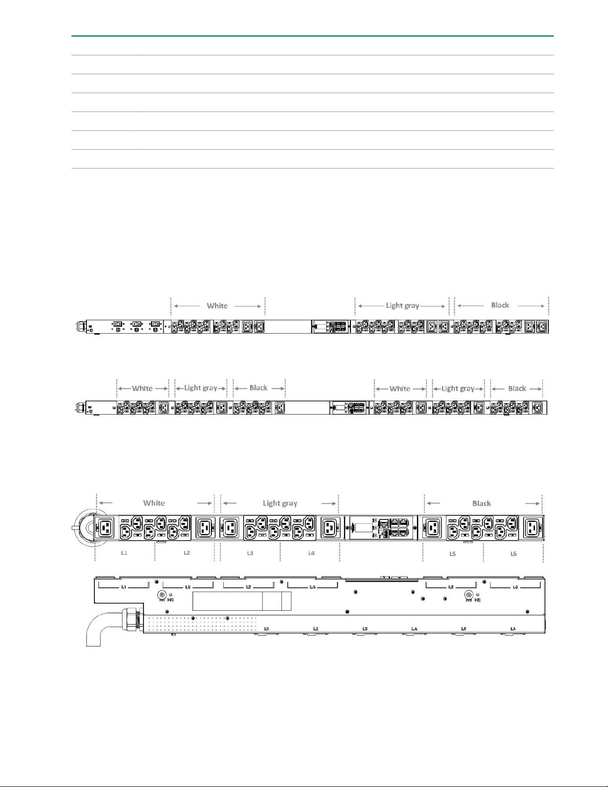
Load segment and phase distinction
HPE G2 PDUs have colored receptacles to help distinguish between the different load segments and phases.
All HPE 3Ph PDUs have different colored receptacles (white, light gray, and black) to distinguish the different
phases. All HPE PDUs with breakers have different colored receptacles to distinguish the different load
segments. The one exception to the colored receptacles is shown in the following illustrations. For 1Ph PDUs
with no breakers, the receptacles are all black.
1 1 1
1 1 1
Figure 1: 1Ph PDU example
Figure 2: 3Ph PDU example
There is one exception to the different colored receptacles per load segment. The 3Ph half-height highdensity model has two different load segments on each phase, as shown in the following illustration.
Figure 3: 3Ph half-height high-density PDU example (P9R82A and P9R84A)
14 Introduction
Page 15
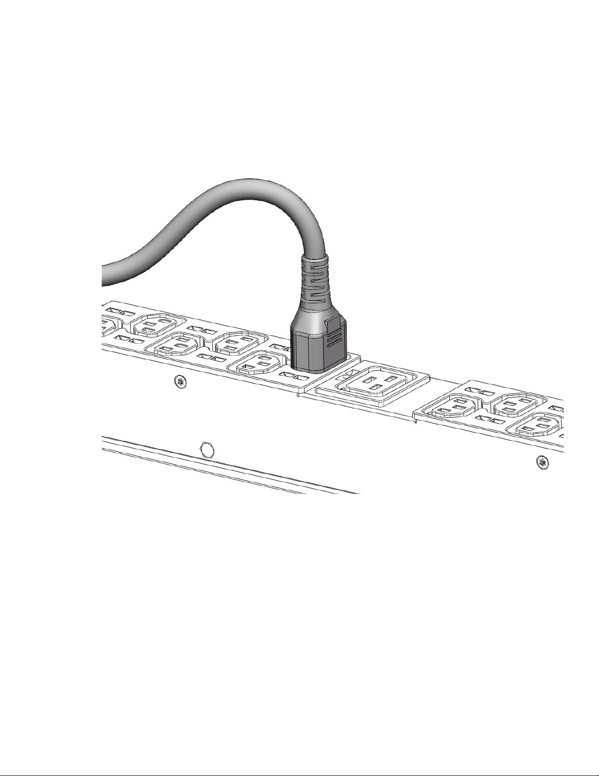
Power cord retention
Integrated cord retention
Each IEC C13 and C19 outlet on the PDU has an integrated cord retention feature that allows you to secure
the cord to the outlet without needing a cord retention bracket.
Procedure
1. Plug in the power cord.
2. Using one of the tie wraps provided, slide the end of the tie wrap into the notch on the PDU next to the
desired outlet, and then wrap it around the cord.
Introduction 15
Page 16
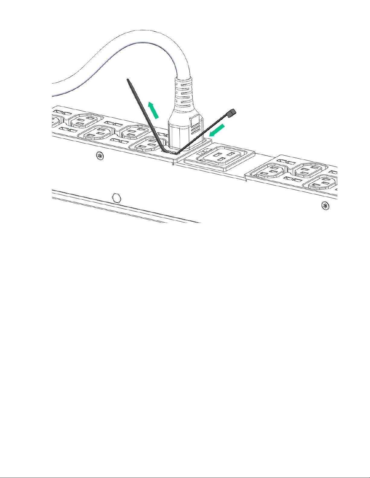
3. Secure the tie wrap.
16 Introduction
Page 17
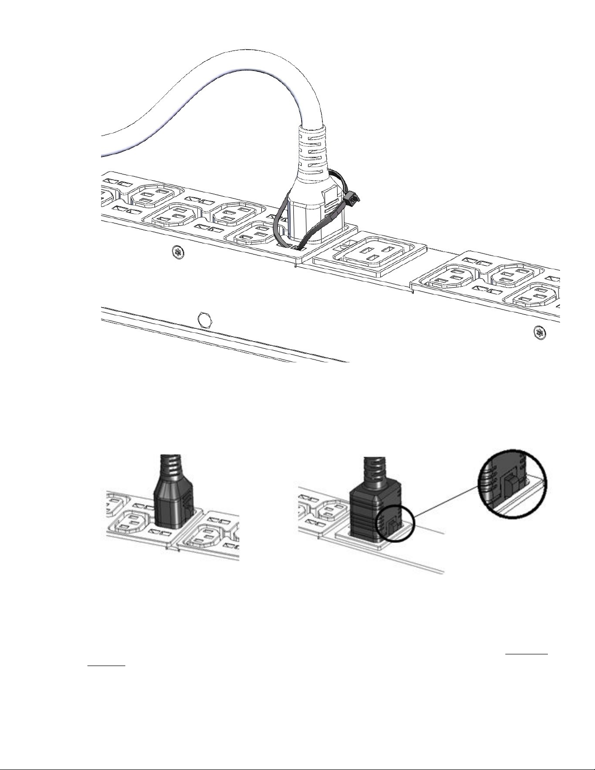
Locking power cord
Optional locking power cords can be used on each IEC C13 and C19 outlet on the PDU. Several lengths are
available to support any configuration. The following illustration shows the locking power cord engaged with
the outlets.
NEMA 5-20R outlet retention bracket
PDUs with 5-20R outlets require installation of a separate retention bracket to secure the equipment power
cord at the outlet. For instructions on how to install the retention bracket for each form factor, see Installing
the PDU.
Introduction 17
Page 18
Procedure
1. Using the screws provided, attach the bracket to one of the locations shown in the following illustrations, a
- d.
a.
b.
18 Introduction
Page 19
c.
d.
2. Install the PDU into the rack.
3. Feed the tie wrap through the hole in the retention bracket and around the input cord.
Introduction 19
Page 20
20 Introduction
Page 21
Installing the PDU
Required tools
• Phillips screwdriver
• Torx screwdriver
Vertical PDU installation
HPE Vertical PDUs include the following form factor models:
• Half-height
• Mid-height
• Full-height
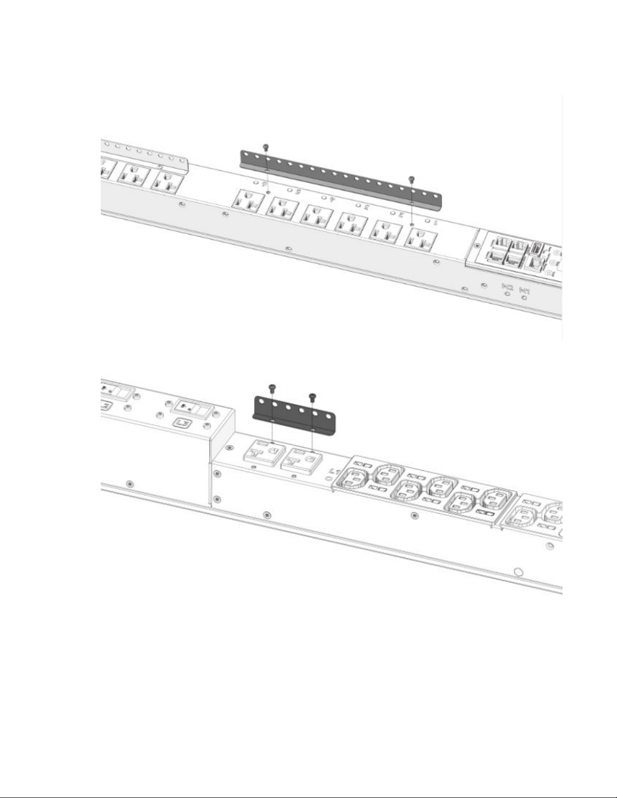
Installing cord retention brackets
The following instructions are for PDUs with NEMA 5-20R outlets, which require the installation of a separate
retention bracket to secure the input power cord at the outlet.
Procedure
1. Attach the bracket to the unit using the screws provided.
2. Install the PDU into the rack.
For more instructions, see Installing mounting hardware.
Installing the PDU 21
Page 22

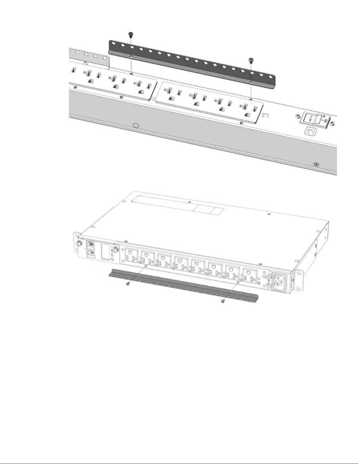
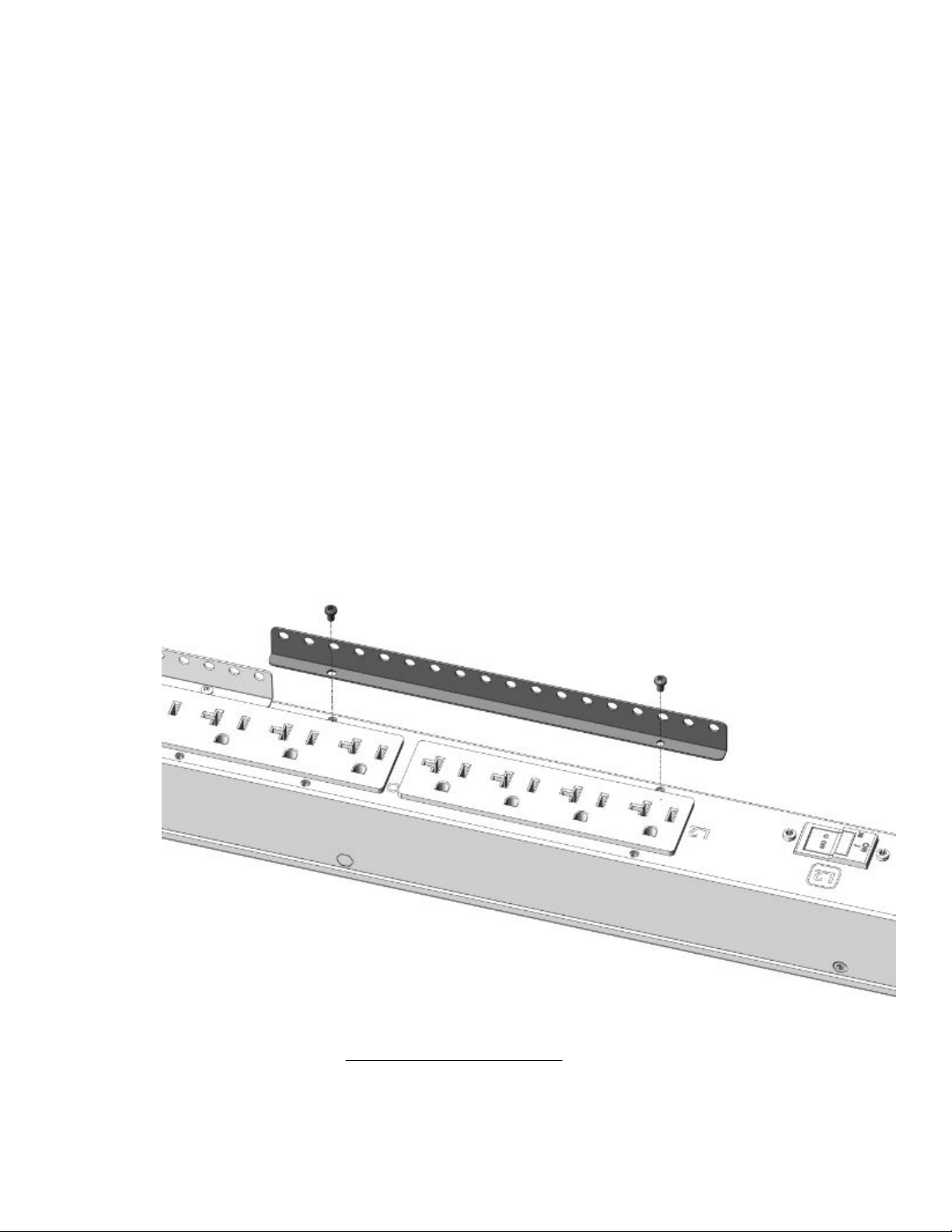
3. Insert the power cord.
4. Feed the tie wrap through the hole in the retention bracket and around the input cord.
22 Installing the PDU
Page 23

Installing the PDU 23
Page 24
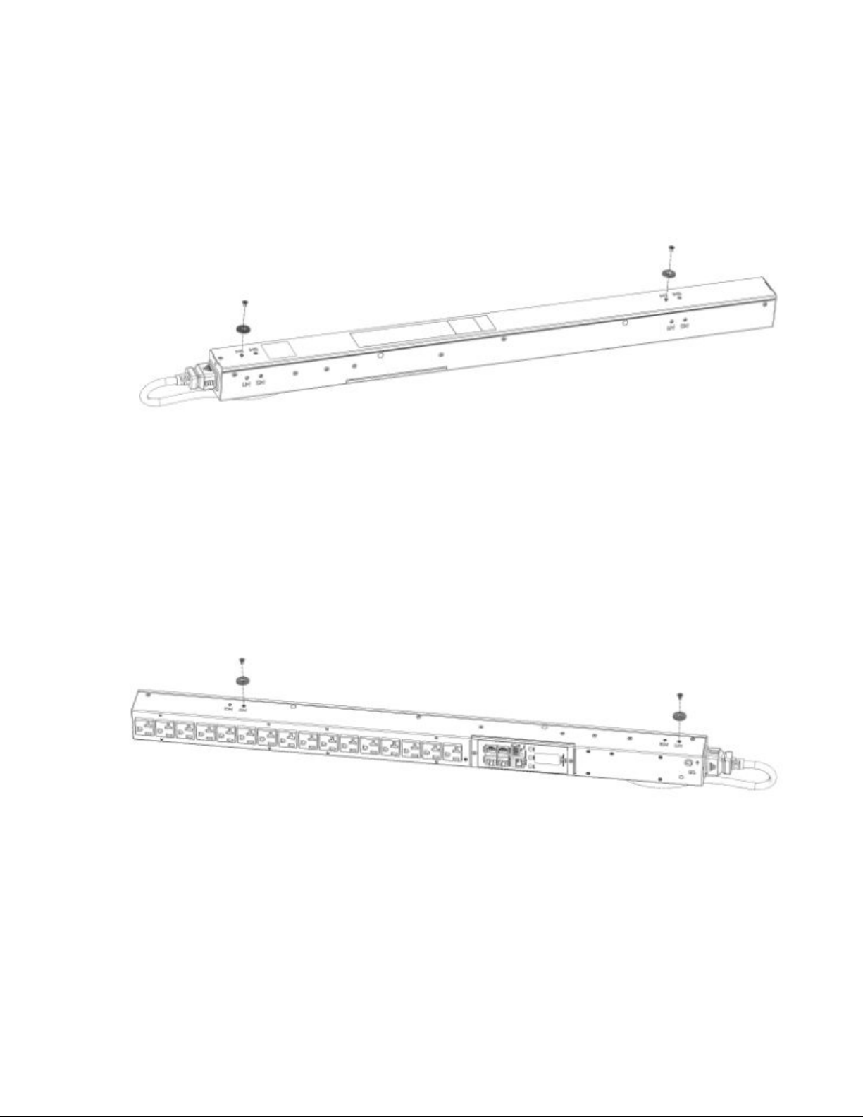
Installing the mounting hardware
To assist with mounting in non-HPE racks, each vertical PDU has two mounting hole locations (M1 and M2)
on the sides and back of the PDU for installing the buttons. When installing the mounting buttons, use either
the M1 or M2 mounting holes as a set.
Installing the mounting button–outlets facing the center of the rack
Procedure
1. Align and install the mounting buttons in the screw holes on the face opposite of the receptacles.
2. Install the PDU by inserting the mounting buttons in the keyhole slots on the PDU mounting bracket in the
rack.
Installing the mounting button–outlets facing the back or front of the rack
Procedure
1. Align and install the mounting buttons in the screw holes on the side of the PDU.
2. Install the PDU by inserting the mounting buttons in the keyhole slots on the PDU mounting bracket in the
rack.
Vertical (0U) PDU—single installation
A single Vertical PDU can be installed with the outlets facing one of the following ways:
• Outlets facing the center of the rack
24 Installing the PDU
Page 25
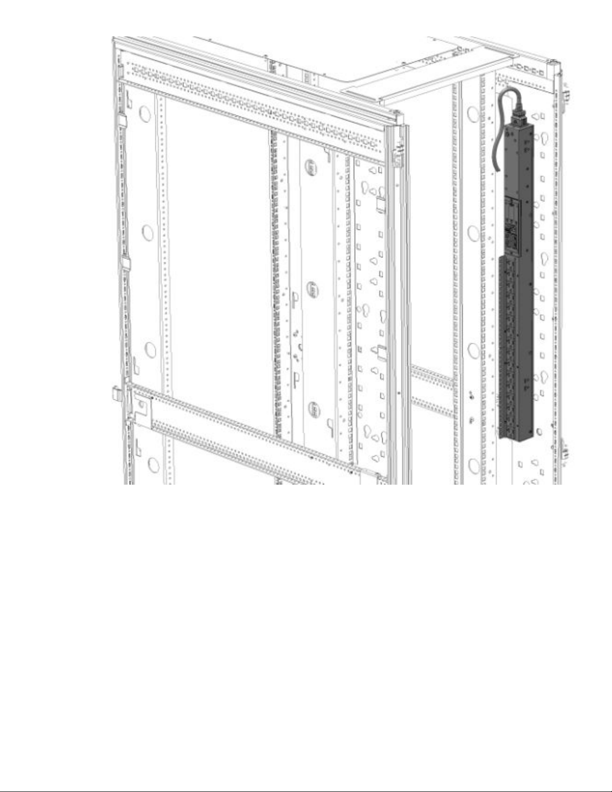
• Outlets facing the back of the rack
Installing the PDU 25
Page 26
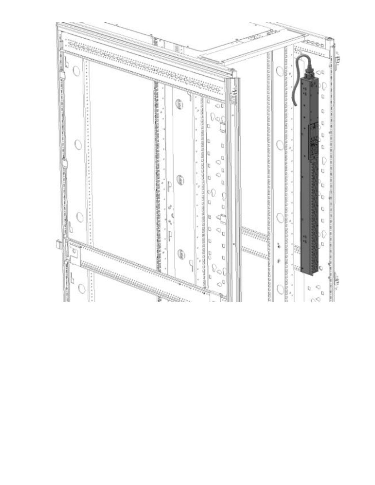
• Outlets facing the front of the rack
26 Installing the PDU
Page 27

NOTE: These installation methods apply to all vertical models except for the high-density models. High-
density units must be installed on its side with the outlets facing the back of the rack. For more information,
see High-density PDU installation.
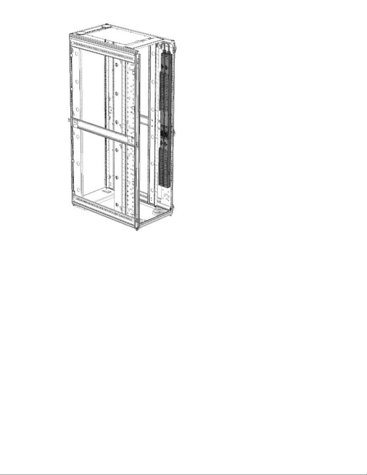
Vertical (0U) PDU—two or more installations
In order for two full-height (in a 42U/47U/48U rack), two mid-height (in a 36U/42U/47U/48U rack), or four halfheight (in a 42U/47U/48U rack) vertical units to be mounted on one side of the rack, all units must be installed
with the outlets facing towards the center of the rack. The following illustrations show how to install the units.
• Two full-height PDUs with outlets facing towards the center of the rack.
Installing the PDU 27
Page 28
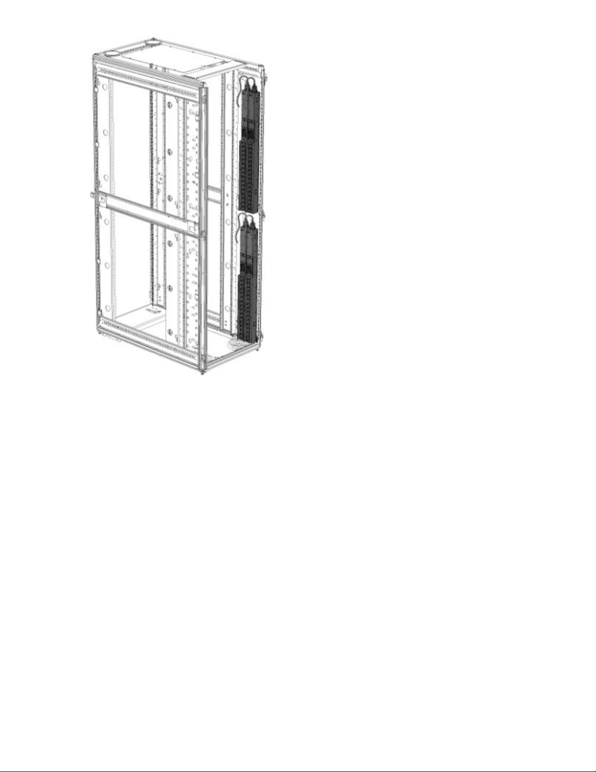
• Two mid-height PDUs with outlets facing towards the center of the rack.
28 Installing the PDU
Page 29
• Four half-height PDUs with outlets facing towards the center of the rack.
Installing the PDU 29
Page 30
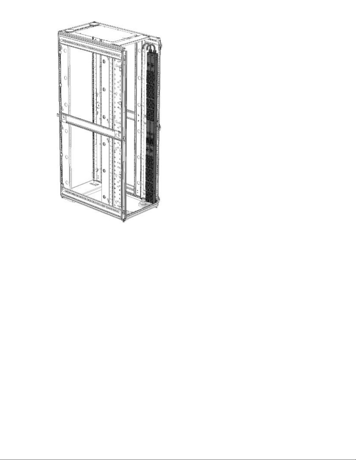
High-density PDU installation
High-density PDUs have a unique form factor and are available in the following models:
• Full-height
30 Installing the PDU
Page 31

• Half-height
Installing the PDU 31
Page 32

High-density PDUs must be installed on its side with the outlets facing the back of the rack.
NOTE: Only one full-height PDU can be installed on each side of the rack, and only two half-height PDUs can
be installed on each side of the rack.
PDU shipping retention for rack transportation
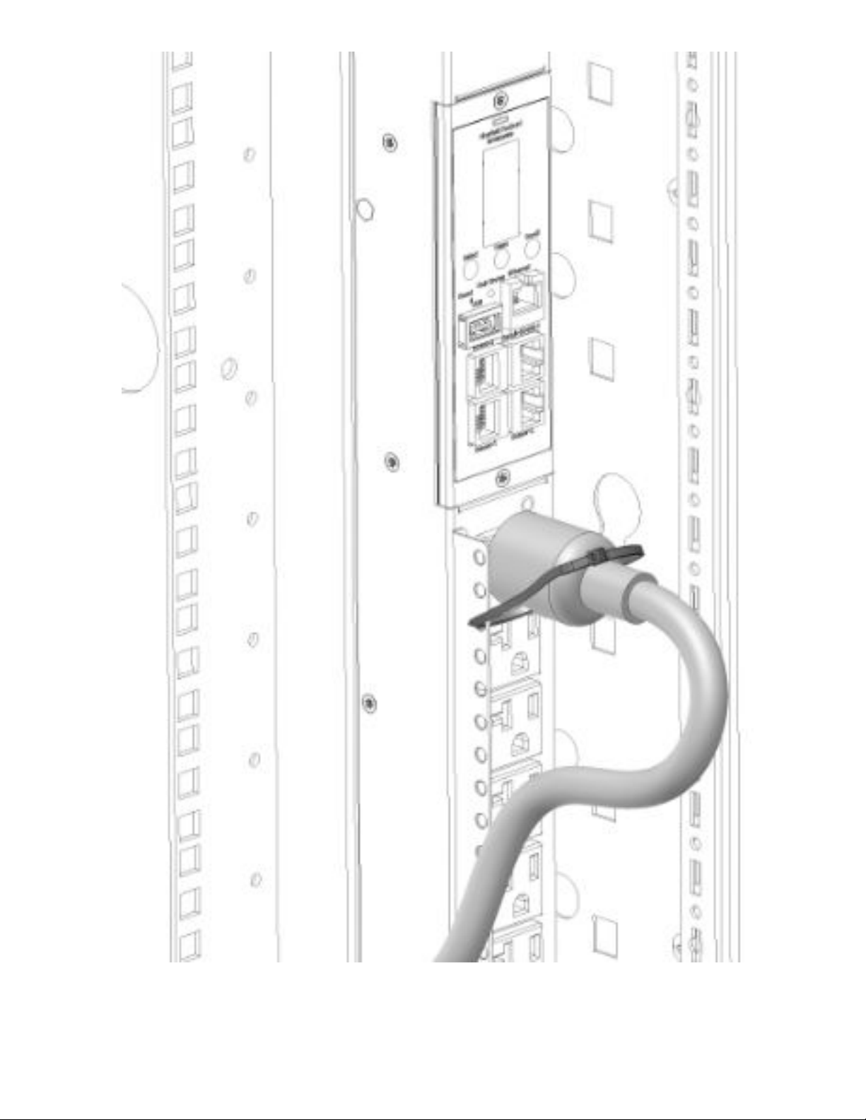
For vertical PDUs with attached input power cord (mid-height and full-height models)
For rack transportation, mid-height and full-height vertical units with an attached input power cord must be
secured using a tie wrap around the input cord and the rack frame.
32 Installing the PDU
Page 33

For Vertical PDUs with detached input power cord and for all half-height models
For rack transportation, Vertical units with a detached input power cord and all half-height units must be
secured using the shipping retention locking tape.
Procedure
1. Remove the adhesive backing from only one side of the shipping retention locking tape.
Installing the PDU 33
Page 34

2. Place the locking tape directly above the unit on the rack PDU mounting bracket.
34 Installing the PDU
Page 35

Installing the PDU 35
Page 36

NOTE: If the PDU must be removed from the rack, remove the top piece of the locking tape and lift the unit
out of the rack.
Installing a vertical PDU in an HPE standard G1 or 10K series rack
Installing a PDU in an older HPE 10K series rack requires option kit H6L32A, which is purchased separately.
Procedure
1. Install the brackets on the PDU.
36 Installing the PDU
Page 37

2. Install the PDU in the rack frame.
Installing the PDU 37
Page 38

1U PDU installation
Installing cord retention brackets (PDUs with NEMA 5-20R outlets)
PDUs with 5-20R outlets require installation of a retention bracket to secure the input power cord at the outlet.
Procedure
1. Attach the retention bracket to the unit using the screws provided.
38 Installing the PDU
Page 39

2. Install the PDU into the rack.
For more information, see Mounting hardware installation.
3. Insert the power cord.
4. Feed the tie wrap through the hole in the retention bracket and around the input cord.
Mounting options
The 1U PDU can be installed in any 1U location of the rack, or in the true 0U space between the RETMA
rails, with the outlets facing down.
Installing the PDU 39
Page 40

Mounting hardware installation
Mounting the 1U PDU in a U position of the rack
Procedure
1. Attach the mounting brackets to the unit using the screws provided.
40 Installing the PDU
Page 41

2. Install the cage nuts in the desired U location.
3. Screw the mounting bracket ears into the RETMA rail surface at the U location where the cage nuts were
installed.
Installing the PDU 41
Page 42

Mounting the 1U PDU in a U position between the RETMA rails
Procedure
1. Attach the 0U mounting brackets to the unit using the screws provided.
2. Insert the mounting screws in the desired 0U location on the RETMA rails.
42 Installing the PDU
Page 43

3. Rest the cutout on the end of the bracket on the screw and pivot the PDU until the holes line up with the
hole in the bracket.
Installing the PDU 43
Page 44

4. Insert and tighten the screws provided through the bracket into the holes in the RETMA rails of the rack.
44 Installing the PDU
Page 45

2U PDU installation
Installing cord retention brackets (PDUs with NEMA 5-20R outlets)
Procedure
Install the power cord retention bracket for 2U PDUs with 5-20R outlets.
NOTE: No cord retention bracket is required for 2U PDUs with IEC C13 and C19 outlets.
Installing the PDU 45
Page 46

Mounting options
This unit can be installed in any U location of the rack.
Mounting hardware installation
Procedure
1. Attach the mounting brackets to the unit. Each bracket requires four screws on each side.
2. Install the cage nuts at the desired U locations.
46 Installing the PDU
Page 47

3. Install the PDU.
Installing the PDU 47
Page 48

Grounding the PDU
Connecting the ground bonding cable
The PDU chassis has an external ground bonding point. The ground bonding screw is provided as an
attachment point for conductors. Use a ground bonding cable if the rack contains any conductors for
functional grounding or bonding of ungrounded metal parts. This bonding point can also be used to bond the
PDU to a known earthed reference terminal in the building. Per international regulatory requirements, the
primary Safety Earth Bond connection is contained in the PDU as a part of the branch circuit cabling and plug.
The ground bonding point is on the surface with the receptacles on all PDUs, except for the high density
models where the ground bonding point is on the surface with the circuit breakers.
48 Installing the PDU
Page 49

Installing the PDU 49
Page 50

Connecting the PDU
Connecting the PDU to a power source
Always follow local and national codes when installing the PDU. The PDU must be connected to a dedicated
circuit protected by a branch circuit breaker matching the PDU input plug type.
NOTE: Make sure that the PDU power cord is long enough to reach the PDU power source.
Procedure
1. Turn the feed circuit breaker Off.
2. Make sure that all circuit breakers on the PDU are set to On.
3. Connect the PDU to an appropriately rated branch circuit.
NOTE: See the label on the PDU for the input ratings.
4. Turn the feed circuit breaker On.
The OLED screen displays a status bar when the PDU operating system is loading. When complete, the
Main Menu displays on the OLED screen. On Switched PDUs and Switched and Metered PDUs, a light
indicates each outlet as it is powered up.
Network management module
The Hewlett Packard Enterprise G2 Series Metered, Switched, and Metered & Switched Power Distribution
Units have an integral and hot swappable Network Management Module. The Network Management Module
contains the OLED interface, control buttons, USB, Ethernet, Serial and Sensor ports, and a recessed Reset
Button.
50 Connecting the PDU
Page 51

Using the reset button
Press and hold the Reset button for 8 seconds to recover from a Network Management Module
communication failure.
NOTE: Pressing the Reset button only reboots the Network Management Module. It does not change the
Energy (KWh) value and it does not affect the output voltage.
Connecting the PDU to a LAN
Connecting the PDU to a LAN provides communication through an Internet or intranet connection. You can
monitor the PDU from any computer connected to the same network. The PDU is configured to use Dynamic
Host Configuration Protocol (DHCP) by default. If an IP address has been assigned successfully, it is
displayed on the OLED screen.
Procedure
1. Locate the Ethernet cable.
2. Connect one end of the cable to the Ethernet port on the PDU, and then connect the other end of the cable
to the Ethernet port on the router (or other LAN device).
Connecting the PDU 51
Page 52

Connecting the PDU to a computer serial port
If you cannot connect to a network, change the network setting using the serial interface.
52 Connecting the PDU
Page 53

Procedure
1. Connect the PDU to a computer serial port, and then set the baud rate for a terminal program.
2. Use a CLI command to enable DHCP or set a static IP address.
3. Verify access to the web interface.
The Ethernet LED on the PDU front panel indicates the communication status by color and display activity.
The recessed Reset button restarts the PDU.
Setting up serial communication
You can configure network settings using a serial connection between the PDU and a laptop computer. You
can use the optional RJ45-DB9 cable or you can make your own cable by creating a unique pinout. For more
information, see Serial cable pinout to create your own cable.
Procedure
1. Verify that the computer has a serial port.
If your computer does not have a DB9 serial connector, but has a USB connector, obtain a USB-to-DB9
adapter to convert the computer USB port to a DB9 serial port.
2. Using the optional RJ45-DB9 cable, connect the RJ-45 end to the port labeled Serial+RS485-1 on the front
panel of the PDU and then connect the DB9 end of the cable to the serial port on the computer.
3. Open the terminal emulation program (HyperTerminal or PuTTY) on the computer and select the serial port
connection (such as COM1).
4. Set the communications port.
• Bits per second: 115200
• Data bits: 8
Connecting the PDU 53
Page 54

• Parity: None
• Stop bits: 1
• Flow control: None
5. Use the default initial login credentials.
The user name and password are case sensitive.
• User name: admin
• Password: 12345678 (or your new password)
The HPE> prompt appears after you have log in.
6. To configure the network settings, at the CLI prompt, enter the appropriate net command and press Enter.
All commands are case sensitive. Enter ? to for a list of available commands.
a. To enable the IPv4 DHCP by default:
• Enter the following command:
net tcpip dhcp
• Enter Y to confirm and the Network Management Module will reboot.
b. To set a static IPv4 configuration:
• Enter the following command:
net tcpip static ip-address netmask gateway
For example, net tcpip static 192.168.1.100 255.255.255.0 192.168.1.1
• Enter Y to confirm and the Network Management Module will reboot.
54 Connecting the PDU
Page 55

Remote configuration
Dynamic Host Configuration Protocol (DHCP)
The PDU is DHCP compatible. If the network does not use a DHCP server, see
connection. When connected to the network, the PDU automatically obtains an IP address through DHCP. If
necessary, log in to the web interface to configure the PDU and assign a static IP address.
Procedure
1. Connect a standard Ethernet patch cable to the Ethernet port on the PDU.
2. Connect the other end of the Ethernet cable to the LAN.
3. To confirm connectivity to the network, make sure the Ethernet port on the PDU shows a solid green light
on the left and a flashing yellow light on the right.
4. Use the menu buttons to look up the IP address of the device on the OLED display by selecting Setup >
Network > IPv4 or IPv6 as applicable.
5. In a standard web browser, enter the PDU IP address and configure the PDU described in Web
configuration.
Web configuration
Supported web browsers
• Mozilla Firefox for Windows
Connecting through a serial
• Mozilla Firefox for Linux
• Mozilla Firefox for HPE-UX
• Windows Internet Explorer
• Google Chrome
Logging in to the web interface
Procedure
1. Open a supported web browser, and then enter the IP address of the PDU.
Remote configuration 55
Page 56

• If a user name and password were configured during the Network Configuration Setup, enter the user
name and password in the appropriate fields. Press Login or Enter.
• If a user name and password were not configured during the Network Configuration Setup, use the
default user name, admin, and password, 12345678. For security purposes, change the password
upon login.
Changing the password
Procedure
1. At initial login, change the password.
a. The Change Password window opens.
b. Enter the current password, and then enter the new password twice to confirm.
Passwords must be between 8 and 32 characters.
c. To complete the password change, click Change Password.
2. After the initial login, change the password.
a. Select User Administration > Change Password.
The Change User Password window opens.
b. Enter the old password, and then enter new password twice to confirm.
Passwords must be between 8 and 32 characters.
c. To complete the password change, click Change Password.
Logging out
To prevent unauthorized changes to the system, users must log out after each session.
Procedure
1. Click the user-name icon in the top right corner of the screen.
2. Select Log Out from the drop-down menu.
Access privileges
There are two levels of access privileges:
• Full
• Read-only
The PDU includes a standard Full profile and a standard Read-only profile. The Full profile is typically the
system administrator and includes the Administrative Role with full operating permissions. The default Readonly profile includes the default User Role permissions.
All users must be added by the Full user. Users are defined by their unique login credentials and user role.
The level of access privilege determines what the user can see and which actions the user can perform. The
level of access privilege also determines which menu items the user can access and which fields are
56 Remote configuration
Page 57

displayed on setting and configuration dialog boxes. Before setting up users, determine the Roles that will be
required. Each user must be assigned a Role, which defines the permissions granted to the user.
Role Default permissions
Full Full permissions that cannot be modified or deleted.
Read-only
Customized Permissions for user customized roles can be set as needed.
User Accounts
The User Settings page lets you add a new user/role, configure LDAP and RADIUS, set session
management, change the temperature units, and set the password policy.
IMPORTANT: LDAP and RADIUS cannot be configured at the same time.
Limited permissions that can be modified or deleted. By default, these permissions
include the following:
• Change Input Phase Setting
• Change Circuit Breaker Setting
• Change Outlet Setting
• Change Own Password
• Change Event Settings
To access User Settings, select Admin > User Accounts.
Adding a user
Procedure
1. On the User Settings page, click Add User in the top right corner.
2. Add a user name, set the password, select the desired role, and click Save.
The changes are displayed in the Users list.
Remote configuration 57
Page 58

Adding a user role
Procedure
1. On the User Settings page, click Add Role in the top right corner.
2. Enter a new role name and description, and set the administrator privileges, if required.
3. Click Save.
The new role is displayed in the Roles list.
Modifying users and roles
Procedure
1. Select User Administration > Users.
2. Click the Edit button next to the user/role you want to modify.
NOTE: All roles can be edited except for the default Administrator.
3. Update the user profile or role.
4. Click Save.
Deleting a user profile
Procedure
1. Select User Administration > Users.
2. Find the user name or role you want to delete.
3. Click the red X next to the user or role to delete.
NOTE: You cannot delete the default Administrator user.
4. Click Delete.
Configuring LDAP
IMPORTANT: LDAP and RADIUS cannot be configured at the same time.
LDAP configuration can be set to access the Active Directory.
Procedure
1. On the User Settings screen, click the edit icon next to LDAP configuration.
2. Configure LDAP to access the Active Directory (AD) by choosing one of the following:
• Open LDAP
• Microsoft Active Directory
3. Enter the following information:
58 Remote configuration
Page 59

• Server address
• Port number
• Port type
• Base DN
• User search DN
• Login name attribute
• User entry object class
• Test name
• Password
4. In the Bind DN field, enter the name of the account to be used to access the AD.
For example: CN=myuser,CN=Users,DC=EMEA,DC=mydomain,DC=com
5. In the Base DN for Search field, enter DC=subdomain,DC=mydomain,DC=com.
6. In the Login Name Attribute field, enter sAMAccountName (typically).
7. In the User Entry Object Class field, enter person.
8. Add a role name PDUAdmin with the admin privilege.
NOTE: The role must be added before testing the configuration.
9. Test the configuration.
After successful testing, enable and save the LDAP configuration.
Configuring RADIUS
IMPORTANT: LDAP and RADIUS cannot be configured at the same time.
Procedure
1. Navigate to the User Accounts screen in the web UI.
2. Enter the RADIUS Server details for RADIUS Configuration, and then enable RADIUS configuration.
• Server—<Radius Server IP>
• Secret—<Secret Passphrase>
Add a user role named RADIUS with the admin privileges.
3.
4. Logout of the web UI.
5. Verify that the RADIUS Server is enabled in the Network.
6. Log in to the web UI with username and password you configured for the RADIUS server.
You can now log in to the PDU and access the webpage.
Remote configuration 59
Page 60

Creating a certificate and private key
Create sha1/sha256 and 1024bits/2048bits certificate and private key for the PDU..
Prerequisites
The PDU needs the following environments to create a certificate and private key.
• Operating system—Linux
• Apps—OpenSSL
Procedure
1. Open Terminal on your Linux operating system.
2. Enter mkdir cer.
3. Enter cd cer.
4. Enter openssl req -x509 -$1 - newkey rsa :$ 2 - keyout cert.key -out cert.crt -
days $3 -nodes.
NOTE: You can generate different types of certificates and private keys based on different $1, $2 and $3.
To generate the different certificate and private keys, replace $1, $2 and $3 with the following options:
• $1—sha1 or sha256
• $2—1024 or 2048
• $3—valid period of certificate
For example, openssl req -x509 -sha256 - newkey rsa:2048 - keyout cert.key -out
cert.crt -days 1024 -nodes. In this case, we are trying to generate sha256/2048bits certificate
and private key that can be valid for 1,024 days.
5. To enter the following information, follow the instructions.
• Country name
• State
• Locality name
• Organization name
• Organizational unit name
• Common name
• Email address
6. Navigate to the cer folder and obtain the cert.crt and cert.key.
7. Login to the PDU with the GUI>Network Setting>Web/ RESTapi Access Configuration.
8. Make sure that the access is set to web access>Https and web port> 443, RESTapi Access>enable.
9. Click the Set Certificate Key icon, and then choose SSL Certificate Key Length (1024/2048) bits.
10. Upload the cert.crt and cert.key.
60 Remote configuration
Page 61

11. Wait for the rebooting to complete.
12. Log in to the IP address of the PDU through https.
You will see that the secure connection is established by the customized Certificate or you can check the
connection on the SSH terminal by entering net cert, which will print the certificate information.
13. To cancel the customized certificate, enter net cert def in the SSH terminal.
14. The PDU will restart automatically.
Session management
Use the Session Management section of the User Settings page to set the number of session retries
allowed, enable or disable the session retries, and set the session timeout value and lockout time.
Procedure
1. Select User Administration > Users.
2. Edit the Session Management values, and then click Save.
Password policy
Use the Password Policy setting to change the following:
• Password aging interval
• Minimum and maximum password length
• Characters required in the password (lowercase, uppercase, numeric, or special characters)
To edit the Password Policy, select Administration > User accounts.
Remote configuration 61
Page 62

Web menu overview
Number Icon Description
1 The search icon allows you to enter keywords and search for related
results.
2 The home icon provides an overview of the PDU with access to
Dashboard, Alarms, Identification, and Control & Manage.
3 The Alarm icon provides details of the active critical alarms and active
warning alarms.
4 This icon provides information about the PDU can be found using this
icon. You can also click user guide and license to for assistance.
5 This icon allows you to select one of the following languages: English,
Chinese, French, Italian, German, Spanish, and Japanese.
6 This icon provides the logs of the PDU, which you can be view and
download.
Table Continued
62 Remote configuration
Page 63

Number Icon Description
7 This icon allows you to set up Network Settings, System Management,
SNMP Manager, Email Setup, Event Notifications, Trap Receiver, and
Thresholds.
8 This icon shows who is logged in (user or admin). You can change
passwords and manage user accounts from this page.
Remote configuration 63
Page 64

Web menu options
Menu Illustration
Overview
64 Remote configuration
Alarms
Page 65

Menu Illustration
Help
Table Continued
Remote configuration 65
Page 66

Menu Illustration
Language
66 Remote configuration
Page 67

Menu Illustration
Logs
Remote configuration 67
Page 68

Menu Illustration
Settings
68 Remote configuration
Page 69

Web interface overview
Summary page
The dashboard summary page appears when you log in to the PDU web UI. This page displays the PDU total
load percent (in a doughnut chart), PDU power energy, external sensor information, current, and voltage and
load percent of each load segment.
PDU page
The dashboard PDU page displays the status of load segments and outlets, current, voltage, and power
values, depending on the type of PDU (Metered, Switched, or Metered & Switched).
Remote configuration 69
Page 70

Control & Manage page
Outlet grouping
The Outlet Groups tab is under the PDU# tab on the Control and Manage page. Outlet Groups lists the outlet
groups created, the power control options, and the "Add new outlet group" option. There are two types of
outlet groups:
• Master PDU
• Slave PDU
Hewlett Packard Enterprise recommends not to group outlets from the Master PDU and Slave PDU together.
If you try to group outlets from different PDUs, a "Different Outlet types are selected" caution message
displays.
Creating an outlet group
Procedure
1. Open a supported web browser, enter the IP address of the PDU, and then enter the credentials of the
PDU.
2. Navigate to Home > Control and Manage.
3. Click Outlet Control Enabled to enable outlet control.
4. Click Add New Outlet Group.
70 Remote configuration
Page 71

5. Add a group name and select the outlets you want to group.
You can group a minimum of one outlet and a maximum of twelve outlets.
6. Click Save.
The new outlet group appears in the Outlet Groups tab.
Remote configuration 71
Page 72

Controlling an outlet group
You can apply power controls to an outlet group.
Procedure
1. Select the group name and the power control option from the Group Name and Power Control drop-
down menu.
2. Click Apply.
The group outlets are switched on or off accordingly.
72 Remote configuration
Page 73

Editing an outlet group
You can edit an outlet group name or add or remove outlets from an existing outlet group.
Procedure
1. Select the outlet group you want to edit.
2. Click Edit.
3. Edit the outlet group name, delete an existing outlet, or select a new outlet.
4. Click Save.
Remote configuration 73
Page 74

Deleting an outlet group
Procedure
1. Select the outlet group you want to delete.
2. Click Delete.
3. Click Yes to confirm that you want to delete the outlet group.
Identification page
The Identification page displays system information such as the system name, contact name, email, phone,
and location. It also displays the IP address details and PDU information such as the PDU name, model, part
number, serial number, boot version, web, and firmware and hardware versions. This page also displays the
external sensor information for the PDU.
74 Remote configuration
Page 75

Alarms page
The Alarms page displays the generated alarms. Alarms are categorized by severity level:
• Active critical alarms
• Active warning alarms
The alarms icon displays the count of critical alarms and warning alarms. The count is reduced as the alarms
are cleared. The Alarms page displays the active alarms, the severity, date, and time generated when any
threshold value exceeds or is less than the expected value.
Remote configuration 75
Page 76

View Logs page
The event log lists the events, applications, and audit logs with the time stamp of when the event log was
generated. All user activities are logged and displayed on the View Logs page. You can download an event
log as an Excel sheet or clear an event log by using the Download or Clear button in the top right corner of
the page.
The data log contains entries with the time of each record. The data log configuration lets you set the time
interval and enable or disable the logs. To clear the data logs, click Clear.
76 Remote configuration
Page 77

Network Settings page
The Network Settings page allows you to edit the IP Configuration, Web/REST API access configuration,
SSH/FTP Configuration, Network Time Protocol, Date/Time Settings, and daylight-savings time.
To access the Network Settings page, select Settings > Network Settings.
You can also perform the following tasks on this page:
• Set Certificate Key—Set the SSL certificate key length (1024/2048 bits).
• Change Link Speed— Set the Ethernet link speed (Auto Negotiation, 10/100 Mbps, or 1GMbps).
• Syslog Configuration—Configure the system log. Add the Syslog server address, server port, and then
enable the access to the Syslog.
IP configuration
On the Network Settings page, select the desired options in the IP Configuration section.
Procedure
1. If using IPv4, select one of the following Boot Mode options:
• To manually enter an IP address, select Static, and then enter the following information:
◦ IPv4 address
◦ Network Mask
◦ Gateway
• To autoconfigure the PDU IP address, select DHCP.
Configuring RESTapi access
Remote configuration 77
Page 78

Prerequisites
•
•
Procedure
1. Enter the PDU IP address in Google Chrome and login to the PDU using the credentials.
2. Navigate to the Network Settings page and enable RESTapi Access Configuration.
3. Click Save, and then confirm and apply changes.
The PDU reboots.
4. Open POSTMAN app.
5. Add the basic authentication header that is required for all the query requests.
• For GET request, enter the URL request, basic authentication header with username and password,
and then query the request.
• For POST request, include the json object type with the basic authentication header.
a. Query the URL http://{pdu_ip} /redfish/v1/SessionService/Sessions , along with
the two headers (basic auth and json object type) and the following body:
{
"username":"admin",
"password":"123456789"
}
b. Use the X-Auth Token from the response body along with the other two headers and basic
authentication for any POST request.
• For DELETE request, enter the URL for session or users you want to delete, along with the basic
authentication and send information.
Network Time Protocol and date/time settings
You can set the internal on the PDU either manually or by linking to a Network Time Protocol (NTP) server.
Procedure
1. Set the internal clock in one of the following ways:
• Manually
◦ Use the calendar icon to select the date or enter the date in YYYY-MM-DD format.
◦ Enter the time in HH:MM:SS format, and then select the time format (for example 24-hour).
• Link to a Network Time Protocol (NTP) server
78 Remote configuration
Page 79

◦ Enter the valid primary and secondary NTP server addresses.
◦ Select the desired GMT offset time from the drop-down list.
Daylight savings time
Procedure
1. Enable daylight savings time for the PDU time by setting a 1 hour or 30 minute offset.
2. Enter the start month (Start Month::Week::Day::Time) and end month (End Month::Week::Day::Time), and
then select the time offset.
System Management page
The System Management page allows you to set the system, rack, power panel, and core location
information.
Action Description
Upload Firmware Uploads the firmware file. Select the HPE.bin or HPEvxx.bin file and click
Upload.
Upload Configuration Uploads the configuration file. Create a configuration file and upload the file to the
PDU with the same SKU. The configuration file must be named conf.ini.
Download
Configuration
Default Settings Sets the PDU to its default settings.
Restart Reboots the PDU.
Downloads the configuration file of the PDU with the same settings.
Remote configuration 79
Page 80

Email Setup page
Procedure
1. Navigate to Settings > Email Setup.
2. Edit the SMTP account settings
3. Add the email server address, sender address, and port number, and then set the number of retries
allowed.
4. Enable authentication and set the user name and password, if required.
When server authentication is disabled, user name and password might be empty.
5. Navigate to Email Recipients, add the email address, and then enable the email address.
6. Click Send Test Email and enter the email address.
An SMTP Configuration test mail will be sent to your email address.
Event Notifications page
Procedure
1. Navigate to Settings > Event Notifications.
2. Enable or disable the event notifications you want to receive for emails, SNMP traps, and the Syslog.
80 Remote configuration
Page 81

PDU Thresholds page
Procedure
1. Navigate to Settings > Thresholds.
2. Set the threshold values for PDU power, phase current, phase voltage, circuit breaker current, outlet
power, and external sensors.
PDU power thresholds
Procedure
1. On the PDU Thresholds page, click the PDU Power Threshold edit pencil.
2. Set the threshold values for High Critical, High Warning, Low Warning, or Low Critical.
3. Select the Enable check-box to enable those thresholds to trigger alarms.
Remote configuration 81
Page 82

4. Set the Reset Threshold value and Alarm State Change Delay value.
5. Click Save.
Power Input phases
Procedure
1. In the Input Phases tab of PDU Thresholds page, click the Edit pencil icon for the PDU input current and
voltage phases.
2. Set the current and voltage phase threshold values for High Critical, High Warning, Low Warning, and Low
Critical for each phase.
3. Enable the threshold values to receive the alarms.
4. Set the Reset threshold and alarm state change delay value.
5. Click Save.
Circuit breaker
Procedure
1. In the PDU Thresholds Circuit Breaker tab, click the Edit pencil icon to set the circuit breaker threshold for
each Load Segment.
2. Set the threshold values for High Critical, High Warning, Low Warning, or Low Critical.
3. Enable the threshold values to trigger the alarms.
4. Set the Reset threshold and alarm state change delay value.
5. Click Save.
82 Remote configuration
Page 83

Control Management
When thresholds are enabled for alarms, the PDU generates the alarms in order of priority:
1. Power alarms
2. Circuit breaker
3. Input phase
4. External sensor
5. Outlet alarms
The alarms are checked at 20-minute intervals.
You can set individual thresholds for High Critical, High Warning, Low Warning, and Low Critical. To enable
two or more thresholds, set the condition for the threshold values. For example:
Low Critical less than Low Warning less than High Warning less than High Critical
Procedure
1. To set outlet active power threshold values, click the Edit pencil icon.
2. Set the threshold values for High Critical, High Warning, Low Warning, or Low Critical.
3. Enable the threshold values to receive the alarms.
4. Set the Reset Threshold and Alarm State Change Delay value.
5. Click Save.
Remote configuration 83
Page 84

84 Remote configuration
Page 85

Simple Network Management Protocol (SNMP)
SNMP configuration
IMPORTANT: For SNMP OID (Delta PDU) Pdu3InputPhaseCurrent 1.1, the value is calculated as
Phase Current * sqrt 3 for both Master and Slave. The GUI threshold page displays as "PDU 1-displays
Phase 1 current."
Setting up SNMP
Procedure
1. Access the web interface and log in.
2. Under SNMP Managers, select SNMP General.
The SNMP General page is displayed, which includes SNMP Access and Version.
Setting up the SNMP port
Procedure
1. Navigate to Settings > SNMP Manager.
2. Select SNMP General.
The SNMP General page is displayed.
3. Edit the SNMP Access and Version.
4. Select SNMP Port, and then set the SNMP port number.
Configuring the SNMP V1/V2c user
Procedure
1. Access the web interface and log in.
2. Under SNMP Managers, select SNMP V1/V2c.
The SNMP V1/V2c page is displayed.
3. Verify that SNMP V1/V2c is selected in the SNMP Version field.
4. On the SNMP V1/V2c panel, in the Community column, select the SNMP V1/V2c user to configure.
5. Choose one of the following access rights for the SNMP V1/V2c user:
• Read Community—SNMP V1/V2c user can edit "public" settings.
• Write Community—SNMP V1/V2c user can edit "private" settings.
6. Click Enable.
7. Click Update.
Simple Network Management Protocol (SNMP) 85
Page 86

Configuring SNMP v1/2c Manager
Procedure
1. On the SNMP Management page, click the edit pencil icon of the IP address to be configured.
2. Choose the access rights for the Read community and the Write community.
3. Click Enable.
4. Click Save.
SNMP v3 Manager
86 Simple Network Management Protocol (SNMP)
Page 87

Trap Receiver
Setting up an SNMP trap receiver
Procedure
1. Navigate to Settings > SNMP Manager.
2. Select SNMP Port, and then set the trap port number.
3. Navigate to Settings > Trap Receiver.
4. Edit the SNMPV1 Trap Receiver by setting the name, host IP address, and community string.
5. Click Enable.
6. Click Save.
Configuring users for encrypted SNMP V3 communications
Procedure
1. Navigate to SNMP Managers > SNMP V3.
The SNMP V3 page is displayed.
2. Enter the server name and host IP address.
3. Choose a security level from the drop-down menu:
• NoAuthNoPriv—No authentication and no privacy, default option.
• AuthNoPriv—Authentication and no privacy.
• AuthPriv—Authentication and privacy.
4. Select an authentication method:
Simple Network Management Protocol (SNMP) 87
Page 88

• Select Password as Authentication Phrase or enter a new unique password to use for
authentication, and then enter it again in the Confirm Authentication Pass Phrase field.
• Select Authentication Pass Phrase as Privacy Pass Phrase to use the user's authentication
passphrase as the privacy passphrase, or enter a new privacy passphrase in the Privacy Pass Phrase
field, and then enter it again in the Confirm Privacy Pass Phrase field.
5. Set the authentication password and privacy key.
6. Click Enable.
7. Click Save.
88 Simple Network Management Protocol (SNMP)
Page 89

Configuring local access
Connecting through a serial connection
You can access the following PDU information through a serial connection by running CLI commands.
• System configuration
• Network Configuration
• User Operation
• Device Settings
• Power Measurements
• Switch Outlets On/Off.
A serial connection also requires a terminal emulation program, such as HyperTerminal, or the use of an SSH
client, such as PuTTY.
Communicating through the serial port requires a specialized optional RJ45-DB9 cable, or you can create
your own cable. For more information on making your own cable, see
own cable.
Connecting the PDU to a computer
Serial cable pinout to create your
Procedure
1. Using the optional RJ45-DB9 cable, connect the RJ45 end to the port labeled Serial+RS485-1 on the front
panel of the PDU.
2. Connect the DB9 end of the cable to the serial connector on the computer.
Supported commands
The PDU CLI command set for managing and monitoring the PDU includes the following commands:
?
PDU help query
sys
PDU system configure and setting
net
PDU net application configure and setting
usr
PDU user operation
dev
PDU device setting
pwr
PDU power setting
Configuring local access 89
Page 90

Command variables are represented in command input syntax surrounded by angle braces (< >). Optional
parameters are represented in command input syntax surrounded by straight brackets ([ ]). For data of type
array, the 'x' character as index of array in command input syntax means all indexes.
You must be logged in to the PDU before commands can be sent. See Appendix A: CLI commands, for a
list of all CLI commands.
Logging in with the CLI
The CLI is an alternative method used to manage and control the PDU status and parameters, as well as
basic administrative functions. With the CLI, you can:
• Reset the PDU
• Display PDU and network properties
• Configure the PDU and network settings
• Switch outlets on/off
• View user information
Logging in with HyperTerminal
To log in with HyperTerminal, set the COM settings to the following parameters:
• Bits per second—115200
• Data bits—8
• Parity—None
• Stop bits—1
• Flow control—None
Logging in with SSH through PuTTY
IMPORTANT: To use SSH directly on the Linux Box, upgrade the OpenSSH to 7.6p1 in the Linux OS.
Upgrading the OpenSSH allows direct SSH command execution through the HPE command prompt.
Procedure
1. Verify that SSH is enabled.
a. With the GUI, navigate to Device Configuration > Network Service > SSH.
b. Select the Enable SSH Access check box.
c. Click OK.
2. Open an SSH client (PuTTY).
3. Enter the IP address in the Host Name field.
4. Select the connection type SSH and enter 22 in the Port field.
5. Click Open.
90 Configuring local access
Page 91

6. Enter your user name, and then press Enter.
7. Enter your password, and then press Enter.
You are now logged in to the SSH. For CLI commands, see Appendix A: CLI commands.
NOTE: An SSH connection is not available when serial connection is enabled.
Configuring local access 91
Page 92

92 Configuring local access
Page 93

Controlling outlets using SSH
Procedure
1. Log into the PDU web UI.
2. Navigate to Settings > Network Settings and enable SSH Configuration with the default port.
3. Open PuTTY configuration, and then enter the host name and port number.
4. Enter the PDU credentials, and then connect to the PDU.
5. Type dev ? to list the device setting commands.
6. To check the status of the outlets and to control (turn on/off) the outlets, enter dev outlet pduID
[status/outletindex] [on/off].
7. To check the status of the outlets of PDU1, enter dev outlet 1 status.
• Open means On.
• Closed means Off.
8. To turn on outlet2 and check the status, enter dev outlet 1 1 on.
9. To turn off outlet 2 and check the status, enter dev outlet 1 2 off.
Serial cable pinout to create your own cable
To make your own RJ45-to-DB9 serial cable, the connections are wired as shown in the following illustration.
Configuring local access 93
Page 94

Local display
This section contains operation information for the Hewlett Packard Enterprise G2 Series Metered, Switched,
and Metered & Switched Power Distribution Units.
OLED display
The OLED display provides information about the PDU and connected devices. The OLED window flashes
red when a critical alarm is active. Information about the basic configuration of some settings is available
through the OLED. Information about the full configuration of all settings is available through the remote
interfaces. The OLED display orientation can be changed using an OLED setting. The display can be rotated
0° and 180°.
The PDU has a three-button, graphical OLED interface panel. Use the buttons to change the screen display,
retrieve specific performance data, or change configuration values. The display view can also change
automatically. For example, the display changes to show active alarms as they occur, or particular displays
update due to a change in operating state.
The OLED display has two modes.
• Screensaver mode—Cycles through a set sequence of screens that display current PDU values. Current
values are refreshed every 10 seconds. The user cannot select a custom sequence of screens. The
screensaver displays automatically after 30 seconds of inactivity from the start-up screen, a menu, or a
submenu. Values are refreshed every five seconds.
• Menu mode (OLED main menu)—The settings that display under each high-level (main) menu depend
on your PDU model.
Menu mode
Button When in menu mode When in screensaver mode
Menu Select from the four main menus. Returns to the previous display screen before
Scroll
Select Opens the selected menu. Returns to the previous display screen before
Scrolls down through the list of menu items.
NOTE: A highlighted menu item is ready to
be selected.
LED unit status
The LED will change colors depending on the state of the PDU.
LED state Description
Solid green Normal operation
Solid red Critical alarm
Solid orange Warning Alarm
entering the screensaver mode.
Returns to the previous display screen before
entering the screensaver mode.
entering the screensaver mode.
Blinking orange Disconnected from network
94 Local display
Table Continued
Page 95

LED state Description
Green, red, orange
blinking
Off In USB mode
Upgrading
OLED menu structure
Local display 95
Page 96

Main menu selections
The PDU menu selection hierarchy consists of Setup, Alarms, Power, and Sensors. On the main menu, scroll
down to highlight Setup, and then press Select. Scroll down to select a submenu and press Select to display
the submenu options. To return to the previous menu, press Menu.
Setup menu
The Setup menu provides user configuration options including Network, Device, Screen, Language, USB, and
Units. Depending on the assigned user privileges, only the available options will be displayed.
Network submenu
The Network submenu allows you to customize settings for IP address IPv4 or IPv6. On the Setup menu,
scroll down to Network. Press Select to display the options screen. Scroll down to highlight the selected
option from the menu. To set the values for the selected option, press Select to display the screens. After you
select the values, press Select to set the values as displayed on the screen. To return to the previous menu
press Menu.
96 Local display
Page 97

Device submenu
The Device submenu provides the SKU number, Serial number, MAC address, and Firmware version. On the
Setup menu, scroll down to highlight the Device submenu. Press Select to display the options screen. To set
the values for the selected option, press Select to display the screens. To return to the previous menu, press
Menu.
Local display 97
Page 98

Screen submenu
The Screen submenu allows you to customize settings for Contrast, Rotate, and Always On. On the Setup
menu, scroll down to highlight Screen. To display the screens to set the values for the submenu, press
Select. After you select the values, press Select to set the values as displayed on the screen. To return to the
previous menu, press Menu.
98 Local display
Page 99

Local display 99
Page 100

Language submenu
The Language submenu allows you to select the language. On the Setup menu, scroll down to highlight Lang.
To display the screens to set the values for the submenu, press Select. After you select the values, to set the
values as displayed on the screen, press Select. To return to the previous menu, press Menu.
USB submenu
The USB submenu allows you to upload the firmware file and download the event or data logs. On the Setup
menu, scroll down to highlight USB. To display the screens to set the values for the submenu, press Select.
After you select Yes, to set the values as displayed on the screen, press Select. To return to the previous
menu, press Menu.
100 Local display
 Loading...