

Page 1

HPE FlexFabric 5930 Switch Series
Installation Guide
Part number: 5998-7149s
Document version: 6W103-20160516
Page 2

© Copyright 2016 Hewlett Packard Enterprise Development LP
The information contained herein is subject to change without notice. The only warranties for Hewlett Packard
Enterprise products and services are set forth in the express warranty statements acco mpanying such
products and services. Nothing herein should be construe d as constituting an additional warranty. Hewlett
Packard Enterprise shall not be liable for technical or editorial errors or omissions co ntained herein.
Confidential computer software. V alid license from Hewlett Packard Enterprise required for possession, use, or
copying. Consistent with FAR 12.211 and 12.212, Commercial Computer Software, Computer Software
Documentation, and T e chnical Data for Commercial Items are licensed to the U.S. Government under vendor’s
standard commercial license.
Links to third-party websites take you outside the Hewlett Packard Enterprise website. Hewlett Packard
Enterprise has no control over and is not responsible for information outside the Hewlett Packard Enterprise
website.
Acknowledgments
Intel®, Itanium®, Pentium®, Intel Inside®, and the Intel Inside logo are trademarks of Intel Corporation in the
United States and other countries.
Microsoft® and Windows® are trademarks of the Microsoft group of companies.
Adobe® and Acrobat® are trademarks of Adobe Systems In corporated.
Java and Oracle are registered trademarks of Oracle and/or its affiliates.
UNIX® is a registered trademark of The Open Group.
Page 3

Contents
Preparing for installation ················································································· 1
Safety recommendations ··································································································································· 2
Examining the installation site ···························································································································· 2
Temperature/humidity ································································································································ 3
Cleanliness ················································································································································· 3
EMI ····························································································································································· 3
Laser safety ················································································································································ 4
Installation tools ················································································································································· 4
Installation accessories ······································································································································ 4
Installing the switch ························································································· 7
Installing the switch in a 19-inch rack ················································································································ 8
Installation accessories ······························································································································ 8
Rack-mounting procedures at a glance ··································································································· 10
Attaching the mounting brackets, chassis rails, and grounding cable to the chassis ······························· 11
Attaching the slide rails to the rack ·········································································································· 15
Mounting the switch in the rack ················································································································ 16
Grounding the switch ······································································································································· 18
Grounding the switch with a grounding strip ···························································································· 19
Grounding the switch by using the AC power cord ·················································································· 19
Installing/removing a fan tray ··························································································································· 20
Installing a fan tray ··································································································································· 21
Removing a fan tray ································································································································· 22
Installing/removing a power supply ·················································································································· 23
Installing a power supply ·························································································································· 24
Removing a power supply ························································································································ 25
Connecting the power cord ······························································································································ 26
Connecting the 650W AC power supply ·································································································· 27
Connecting the 650W DC power supply ·································································································· 27
Installing/Removing an interface module ································································································· 28
Verifying the installation ··································································································································· 30
Accessing the switch for the first time ··························································· 31
Setting up the configuration environment ········································································································ 31
Connecting the console cable ·························································································································· 31
Serial console cable ································································································································· 31
USB mini console cable ··························································································································· 32
Connection procedure ······························································································································ 32
Setting terminal parameters ····························································································································· 34
Powering on the switch ···································································································································· 34
Setting up an IRF fabric ················································································ 36
IRF fabric setup flowchart ································································································································ 36
Planning IRF fabric setup ································································································································· 37
Planning IRF fabric size and the installation site ······················································································ 37
Identifying the master switch and planning IRF member IDs ··································································· 37
Planning IRF topology and connections ··································································································· 38
Identifying physical IRF ports on the member switches ··········································································· 39
Planning the cabling scheme ··················································································································· 39
Configuring basic IRF settings ························································································································· 40
Connecting the physical IRF ports ··················································································································· 40
Accessing the IRF fabric to verify the configuration ························································································· 40
Maintenance and troubleshooting ································································· 42
Power supply failure ········································································································································· 42
Fan tray failure ················································································································································· 42
Configuration terminal problems ······················································································································ 42
i
Page 4

No terminal display ··································································································································· 43
Garbled terminal display ·························································································································· 43
Appendix A Chassis views and technical specifications ······························· 44
Chassis views ·················································································································································· 44
HPE 5930-32 QSFP+/HPE 5930-32 QSFP+ TAA ··················································································· 44
HPE 5930-2Slot+2QSFP+/HPE 5930-2Slot+2QSFP+ TAA ····································································· 45
HPE 5930-4Slot/HPE 5930-4Slot TAA ····································································································· 46
Technical specifications ··································································································································· 48
Appendix B FRUs and compatibility matrixes ··············································· 50
Power supplies ················································································································································· 50
Fan trays ·························································································································································· 51
Interface modules ············································································································································ 52
Appendix C Ports and LEDs ········································································· 54
Ports ································································································································································· 54
Console port ············································································································································· 54
Management Ethernet port ······················································································································ 54
USB port ··················································································································································· 54
SFP+ port ················································································································································· 55
QSFP+ port ·············································································································································· 57
1/10GBase-T autosensing Ethernet port ·································································································· 59
LEDs ································································································································································ 59
System status LED ··································································································································· 59
SFP+ port LED ········································································································································· 60
QSFP+ port LED ······································································································································ 60
Management Ethernet port LEDs ············································································································· 60
1/10GBase-T autosensing Ethernet port LEDs ························································································ 61
Fan tray alarm LEDs ································································································································ 61
Appendix D Cooling system ·········································································· 62
HPE 5930-32 QSFP+/HPE 5930-32 QSFP+ TAA/HPE 5930-2Slot+2QSFP+/HPE 5930-2Slot+2QSFP+ TAA
cooling system ················································································································································· 62
HPE 5930-4Slot/HPE 5930-4Slot TAA cooling system ···················································································· 63
Document conventions and icons ································································· 65
Conventions ····················································································································································· 65
Network topology icons ···································································································································· 66
Support and other resources ········································································ 67
Accessing Hewlett Packard Enterprise Support ······························································································ 67
Accessing updates ··········································································································································· 67
Websites ·················································································································································· 68
Customer self repair ································································································································· 68
Remote support ········································································································································ 68
Documentation feedback ························································································································· 69
ii
Page 5

Preparing for installation
Table 1 describes HPE FlexFabric 5930 Switch Series models, power supplies, and fan trays.
Table 1 HPE FlexFabric 5930 Switch Series models, power supplies, and fan trays
Product code HPE description Alias
HPE FlexFabric 5930 switches
JG726A HPE FlexFabric 5930 32QSFP+ Switch HPE 5930-32 QSFP+
JG727A
JH178A HPE FlexFabric 5930 2QSFP+ 2-slot Switch HPE 5930-2Slot+2QSFP+
JH187A
JH179A HPE FlexFabric 5930 4-slot Switch HPE 5930-4Slot
JH188A
Power supplies
JC680A HPE 58x0AF 650W AC Power Supply 650W AC
JH336A
Fan trays
JG552A
JG553A
JH185A
JH186A
HPE FlexFabric 5930 32QSFP+
TAA-compliant Switch
HPE FlexFabric 5930 2QSFP+ 2-slot
TAA-compliant Switch
HPE FlexFabric 5930 4-slot TAA-compliant
Switch
HPE FlexFabric Switch 650W 48V Hot Plug
NEBS-compliant DC Power Supply
HPE X711 Front (Port Side) to Back (Power
Side) Airflow High Volume Fan Tray
HPE X712 Back (Power Side) to Front (Port
Side) Airflow High Volume Fan Tray
HPE 5930 4-slot Back (Power Side) to Front
(Port Side) Airflow Fan Tray
HPE 5930 4-slot Front (Port Side) to Back
(Power Side) Airflow Fan Tray
HPE 5930-32 QSFP+ TAA
HPE 5930-2Slot+2QSFP+ TAA
HPE 5930-4Slot TAA
650W DC
LSWM1HFANSCB
LSWM1HFANSC
LSWE1BFANSC
LSWE1BFANSCB
For regulatory identification purposes, the HPE 5930-32 QSFP+ Switch and HPE 5930-32 QSFP+
TAA Switch are assigned Regulatory Model Numbers (RMNs). The RMNs for these products are
listed below. These regulatory numbers should not be confused with the marketing name HPE
FlexFabric 5930, or the product codes JG726A and JG727A.
Product code RMN Description
JG726A BJNGA-AD0022 HPE FlexFabric 5930 32QSFP+ Switch
JG727A BJNGA-AD0022
HPE FlexFabric 5930 32QSFP+
TAA-compliant Switch
For regulatory identification purposes, the HPE 5930-2Slot+2QSFP+ Switch, HPE
5930-2Slot+2QSFP+ TAA Switch, HPE 5930-4Slot Switch, and HPE 5930-4Slot TAA Switch are
assigned Regulatory Model Numbers (RMNs). The RMNs for these products are listed below. These
regulatory numbers should not be confused with the marketing name HPE FlexFabric 5930, or the
product codes JH178A, JH187A, JH179A, and JH188A.
1
Page 6

Product code RMN Description
JH178A BJNGA-AD0049 HPE FlexFabric 5930 2QSFP+ 2-slot Switch
JH187A BJNGA-AD0049
JH179A BJNGA-AD0050 HPE FlexFabric 5930 4-slot Switch
JH188A BJNGA-AD0050
Safety recommendations
To avoid any equipment damage or bodily injury caused by incorrect use, read the following safety
recommendations before installation. Note that the recommendations do not cover every possible
hazardous condition.
• Before cleaning the switch, remove all power cords from the switch. Do not clean the switch
with wet cloth or liquid.
• Do not place the switch near water or in a damp environment. Prevent water or moisture from
entering the switch chassis.
• Do not place the switch on an unstable case or desk. The switch might be severely damaged in
case of a fall.
• Ensure good ventilation of the equipment room and keep the air inlet and outlet vents of the
switch free of obstruction.
• Connect the yellow-green protection grounding cable before power-on.
• Make sure the operating voltage is in the required range.
• To avoid electrical shocks, do not open the chassis while the switch is operating or when the
switch is just powered off.
• When replacing FRUs, including power supplies, fan trays, and interface modules, wear an
ESD wrist strap to avoid damaging the units.
HPE FlexFabric 5930 2QSFP+ 2-slot
TAA-compliant Switch
HPE FlexFabric 5930 4-slot TAA-compliant
Switch
Examining the installation site
The switch must be used indoors.
You can mount your switch in a rack. To rack-mount your switch, make sure the following
requirements are met:
• Adequate clearance is reserved at the air inlet and outlet vents for ventilation.
• The rack has a good ventilation system.
• Identify the hot aisle and cold aisle at the installation site, and make sure ambient air flows into
the switch from the cold aisle and exhausts to the hot aisle.
• Identify the airflow designs of neighboring devices, and prevent hot air flowing out of the bottom
device from entering the top device.
• The rack is sturdy enough to support the switch and its accessories.
• The rack is reliably grounded.
To ensure correct operation and long service life of your switch, install it in an environment that meets
the requirements described in the following subsections.
2
Page 7

Temperature/humidity
Maintain appropriate temperature and humidity in the equipment room.
• Lasting high relative humidity can cause poor insulation, electricity leakage, mechanical
property change of materials, and metal corrosion.
• Lasting low relative humidity can cause washer contraction and ESD and cause problems
including loose screws and circuit failure.
• High temperature can accelerate the aging of insulation materials and significantly lower the
reliability and lifespan of the switch.
For the temperature and humidity requirements of different switch models, see "Appendix A Chassis
views a
nd technical specifications."
Cleanliness
Dust buildup on the chassis might result in electrostatic adsorption, which causes poor contact of
metal components and contact points, especially when indoor relative humidity is low. In the worst
case, electrostatic adsorption can cause communication failure.
Table 2 Dust concentration limit in the equipment room
Substance Concentration limit (particles/m³)
EMI
Dust
NOTE:
Dust diameter ≥ 5 μm
≤ 3 x 10⁴ (no visible dust on the tabletop over three days)
The equipment room must also meet limits on salts, acids, and sulfides to eliminate corrosion and
premature aging of components, as shown in Table 3.
Table 3
Harmful gas limits in the equipment room
Gas Maximum concentration (mg/m³)
SO
2
H2S 0.006
NH3 0.05
Cl2 0.01
0.2
All electromagnetic interference (EMI) sources, from outside or inside of the switch and application
system, adversely affect the switch in the following ways:
• A conduction pattern of capacitance coupling.
• Inductance coupling.
• Electromagnetic wave radiation.
• Common impedance (including the grounding system) coupling.
To prevent EMI, use the following guidelines:
• If AC power is used, use a single-phase three-wire power receptacle with protection earth (PE)
to filter interference from the power grid.
3
Page 8
• Keep the switch far away from radio transmitting stations, radar stations, and high-frequency
devices.
• Use electromagnetic shielding, for example, shielded interface cables, when necessary.
Laser safety
WARNING!
Do not stare into any fiber port when the switch has power. The laser light emitted from the optical
fiber might hurt your eyes.
The switch is a Class 1 laser device.
Installation tools
No installation tools are provided with the switch. Prepare the following tools yourself:
• Phillips screwdriver.
• ESD wrist strap.
• Marker.
Installation accessories
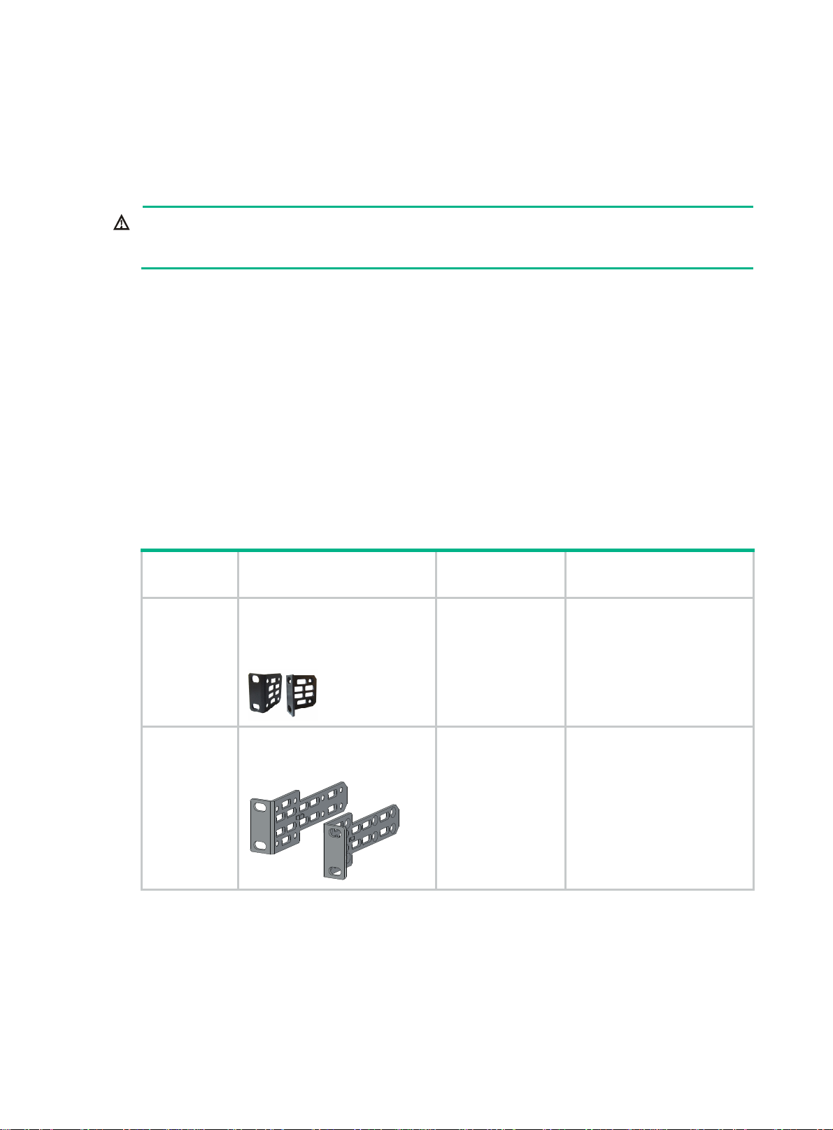
Table 4 Installation accessories
Product
code
5066-0850
5190-0719
Description Quantity Applicable models
1 U mounting bracket kit
(including one pair of mounting
brackets and eight M4
countersunk screws)
Mounting brackets for the HPE
5930-2Slot+2QSFP+/HPE
5930-2Slot+2QSFP+ TAA
• HPE 5930-32 QSFP+
1 kit
1 kit
• HPE 5930-32 QSFP+
TAA
• HPE 5930-2Slot+2QSFP+
• HPE 5930-2Slot+2QSFP+
TAA
4
Page 9
Product
code
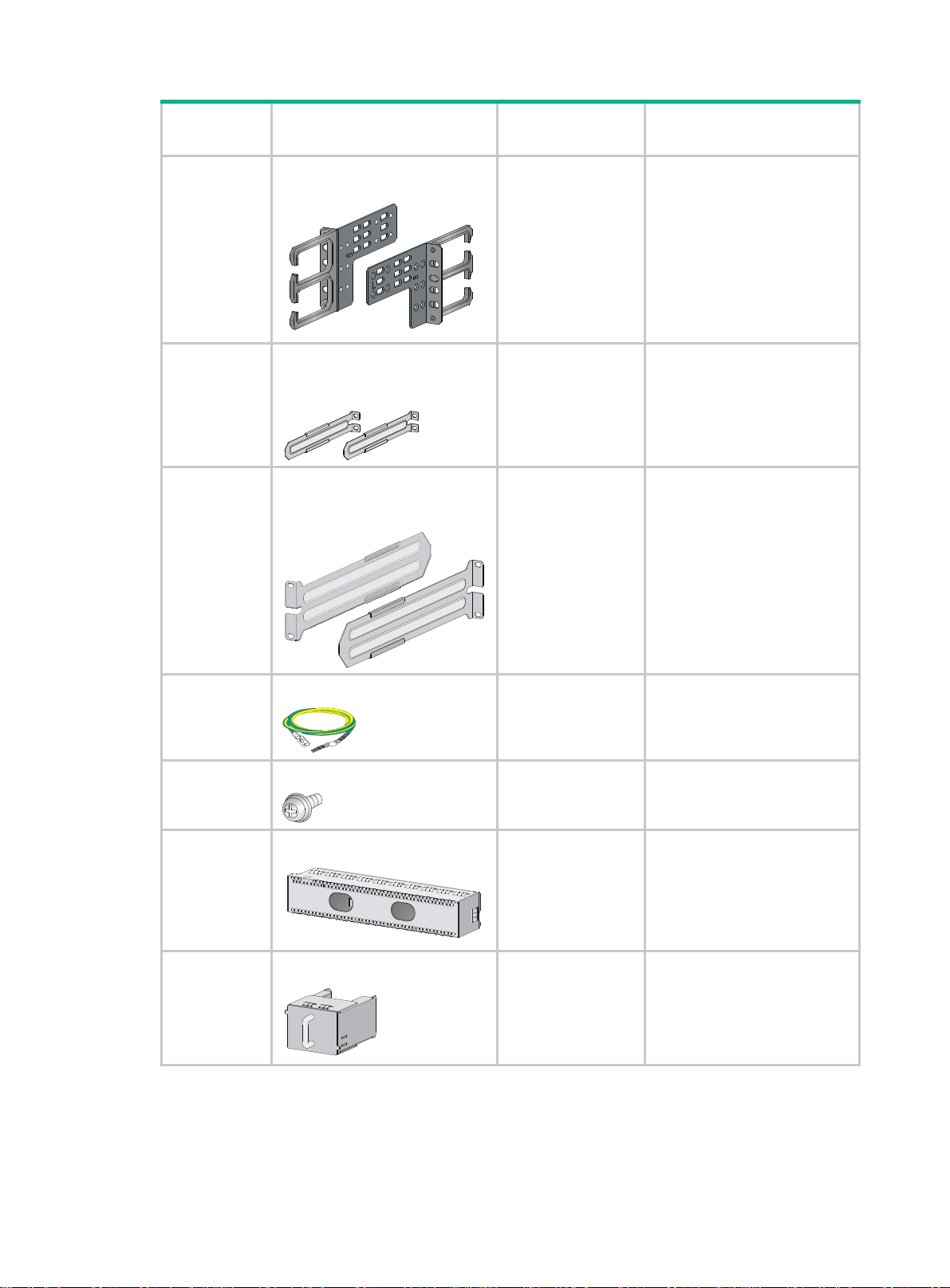
5190-0720
5185-8681
5185-8684
Description Quantity Applicable models
Mounting brackets for the HPE
5930-4Slot/HPE 5930-4Slot TAA
1 kit
1 U short slide rail kit (including
one pair of slide rails and four M4
countersunk screws)
1 kit
2 U short slide rail kit (including
one pair of slide rails and four M4
countersunk screws)
1 kit
• HPE 5930-4Slot
• HPE 5930-4Slot TAA
• HPE 5930-32 QSFP+
• HPE 5930-32 QSFP+
TAA
• HPE 5930-2Slot+2QSFP+
• HPE 5930-2Slot+2QSFP+
TAA
• HPE 5930-4Slot
• HPE 5930-4Slot TAA
5184-6723
5185-9579
5003-2403
5185-8676
Grounding cable
Grounding screw
Interface module filler module
Power supply filler module
1 All HPE 5930 switches
2 All HPE 5930 switches
• HPE 5930-2Slot+2QSFP+
• HPE 5930-2Slot+2QSFP+
1
TAA
• HPE 5930-4Slot
• HPE 5930-4Slot TAA
1 All HPE 5930 switches
5
Page 10
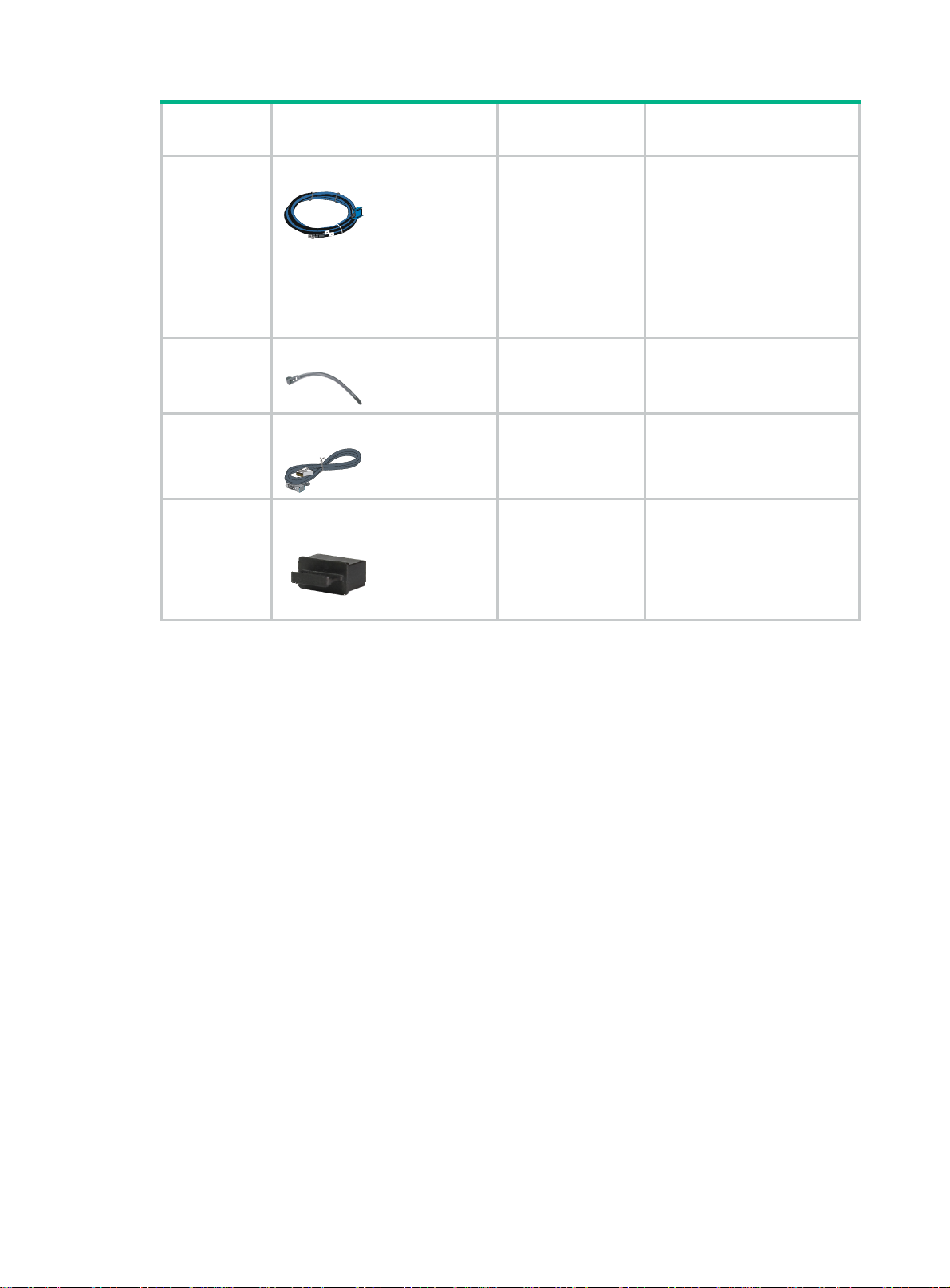
Product
code
5185-8688
5400-0249
5185-8748
5185-8627
5187-9022
Description Quantity Applicable models
DC power cord
The power cord color code
scheme is for illustration only.
The cable delivered for your
country or region might use a
different color scheme.
Removable cable tie
Console cable
QSFP+ dust plug
1 650W DC power supply
1 All power supplies
1 All HPE 5930 switches
• HPE 5930-32 QSFP+
• HPE 5930-32 QSFP+
Optional
TAA
• HPE 5930-2Slot+2QSFP+
• HPE 5930-2Slot+2QSFP+
TAA
6
Page 11
Installing the switch
CAUTION:
Keep the tamper-proof seal on a mounting screw on the chassis cover intact, and if you want to open
the chassis, contact Hewlett Packard Enterprise for permission. Otherwise, Hewlett Packard
Enterprise shall not be liable for any consequence caused thereby.
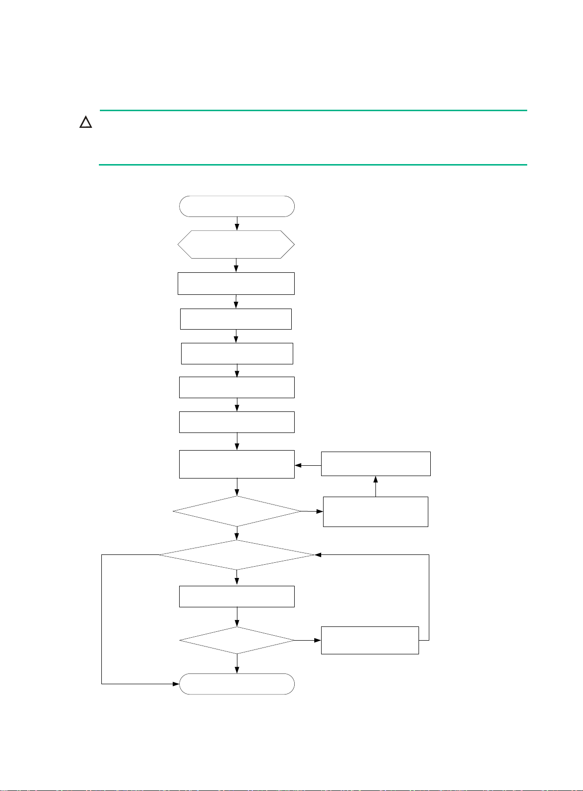
Figure 1 Hardware installation flow
Start
Install the switch
Ground the switch
Install fan trays
No
Install power supplies
Connect the power cords
Verify the installation
Power on the switch
No
Operating correctly?
Yes
Install interface cards?
Yes
Install interface cards
No
Operating correctly? Resolve the problem
Resolve the problem
Power off the switch
Yes
End
7
Page 12
Installing the switch in a 19-inch rack
IMPORTANT:
To close the rack door easily, make sure the rack depth is a minimum of 1000 mm (39.37 in).
Installation accessories
Table 5 Installation accessories
Switch model
• HPE 5930-32 QSFP+
• HPE 5930-32 QSFP+
TAA
• HPE
5930-2Slot+2QSFP+
• HPE
5930-2Slot+2QSFP+
TAA-compliant
• HPE 5930-4Slot
• HPE 5930-4Slot TAA
Mounting
brackets
(provided)
1U high, one pair.
See Figure 2.
1U high, one pair.
See Figure 3.
2U high, one pair.
See Figure 4.
Cable
management
brackets
N/A
N/A
One pair
(provided).
See Figure 4.
Rack mounting rail kit
(provided)
1U high, including one pair of
chassis rails and one pair of
slide rails. See Figure 5.
1U high, including one pair of
chassis rails and one pair of
slide rails. See Figure 5.
h, including one pair of
2U hig
chassis rails and one pair of
slide rails. See Figure 6.
Figure 2 Mounting brackets for the HPE 5930-32 QSFP+/HPE 5930-32 QSFP+ TAA switch
8
Page 13

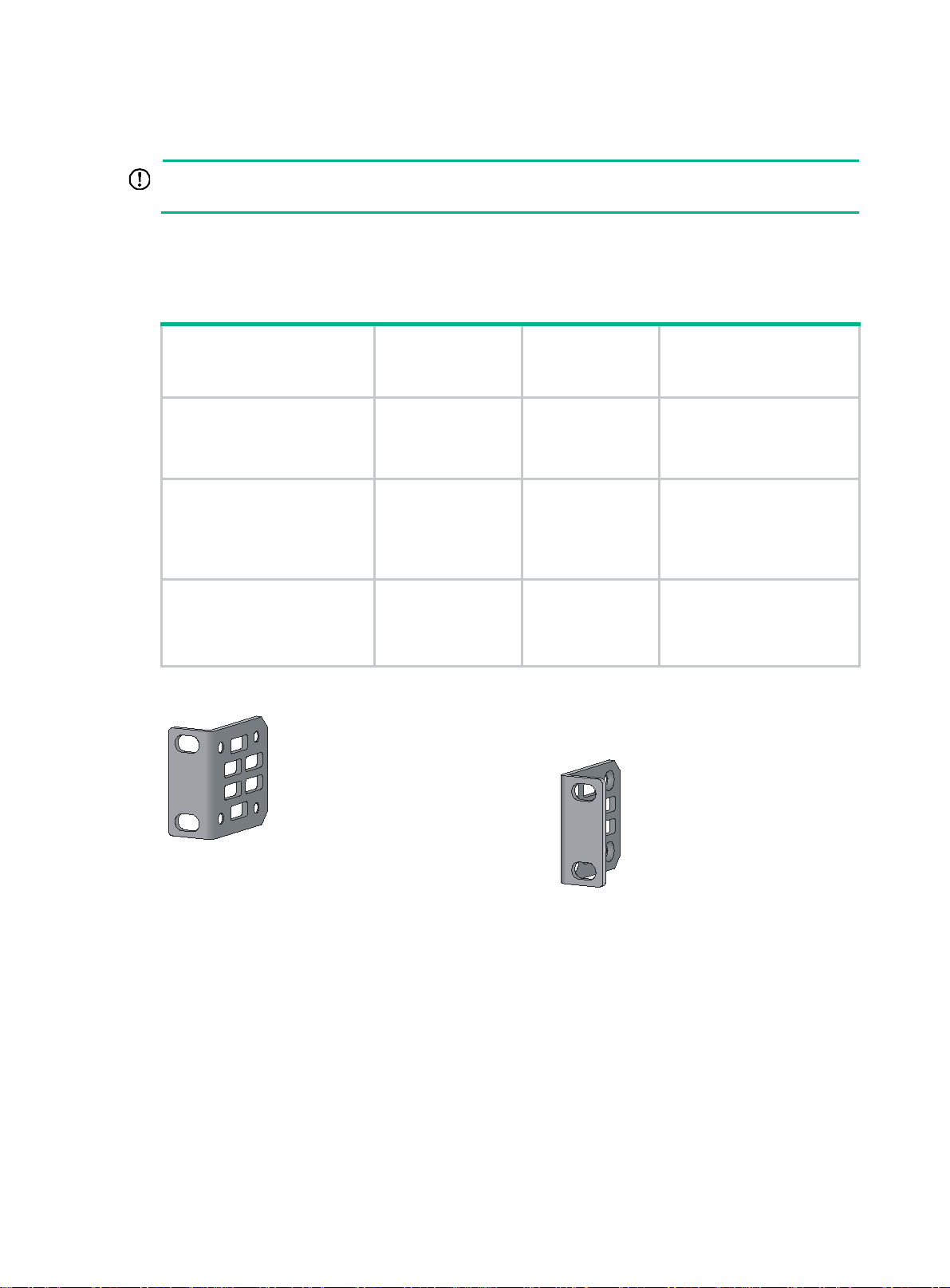
Figure 3 Mounting brackets for the HPE 5930-2Slot+2QSFP+/HPE 5930-2Slot+2QSFP+ TAA
switch
Figure 4 Mounting brackets for the HPE 5930-4Slot/HPE 5930-4Slot TAA switch
1 2
(1) Cable management bracket (2) Mounting bracket
Figure 5 1U rack mounting rail kit
(1) Chassis rail (2) Slide rail
9
Page 14
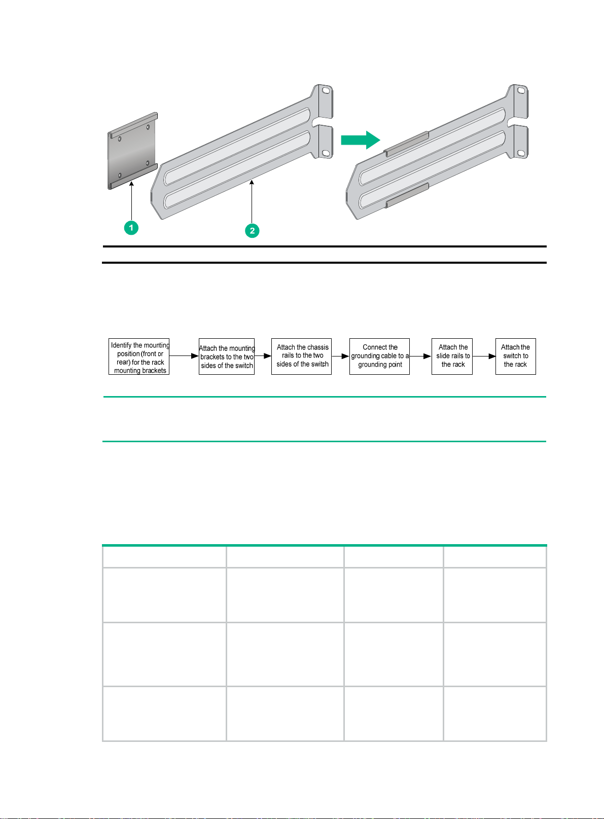
Figure 6 2U rack mounting rail kit
(1) Chassis rail (2) Slide rail
Rack-mounting procedures at a glance
Figure 7 Rack-mounting procedure
NOTE:
If a rack shelf is available, you can put the switch on the rack shelf, slide the switch to an appropriate
location, and attach the switch to the rack with the mounting brackets.
Follow these guidelines when you install the switch in a 19-inch rack:
• The distance between the front and rear posts of the rack must meet the requirements
described in Table 6.
o secure the switch to the rack, you must install not only mounting brackets, but also chassis
• T
rails and slide rails.
Table 6 Distance requirements between the front and rear rack posts
Switch model Installation method Minimum distance Maximum distance
• HPE 5930-32 QSFP+
• HPE 5930-32 QSFP+
TAA
• HPE
5930-2Slot+2QSFP+
• HPE
5930-2Slot+2QSFP+
TAA
Using provided mounting
brackets and chassis rails
Using provided mounting
brackets and chassis rails
405 mm (15.94 in) 854 mm (33.62 in)
520 mm (20.47 in) 789 mm (31.06 in)
• HPE 5930-4Slot
• HPE 5930-4Slot TAA
Using provided mounting
brackets and chassis rails
10
518 mm (20.39 in) 888 mm (34.96 in)
Page 15
Attaching the mounting brackets, chassis rails, and grounding cable to the chassis
The switch has one mounting position near the network ports and one mounting position near the
power supplies for mounting brackets.
The HPE 5930-32 QSFP+/HPE 5930-32 QSFP+ TAA/HPE 5930-4Slot/HPE 5930-4Slot TAA
switches provide three grounding points: primary grounding point (with a grounding sign), auxiliary
grounding point 1, and auxiliary grounding point 2. The HPE 5930-2Slot+2QSFP+/HPE
5930-2Slot+2QSFP+ TAA switch provides two grounding points: primary grounding point (with a
grounding sign) and auxiliary grounding point 1.
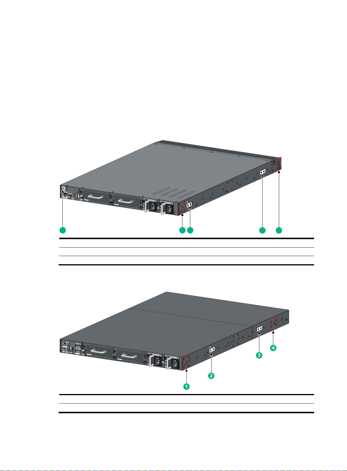
Figure 8 Mounting and grounding positions on the HPE 5930-32 QSFP+/HPE 5930-32 QSFP+
TAA switch
1 2 3
(1) Auxiliary grounding point 2 (2) Power supply-side mounting position
(3) Primary grounding point (4) Auxiliary grounding point 1
(5) Network port-side mounting position
4 5
Figure 9 Mounting and grounding positions on the HPE 5930-2Slot+2QSFP+/HPE
5930-2Slot+2QSFP+ TAA switch
(1) Power supply-side mounting position (2) Primary grounding point
(3) Auxiliary grounding point 1 (4) Network port-side mounting position
11
Page 16
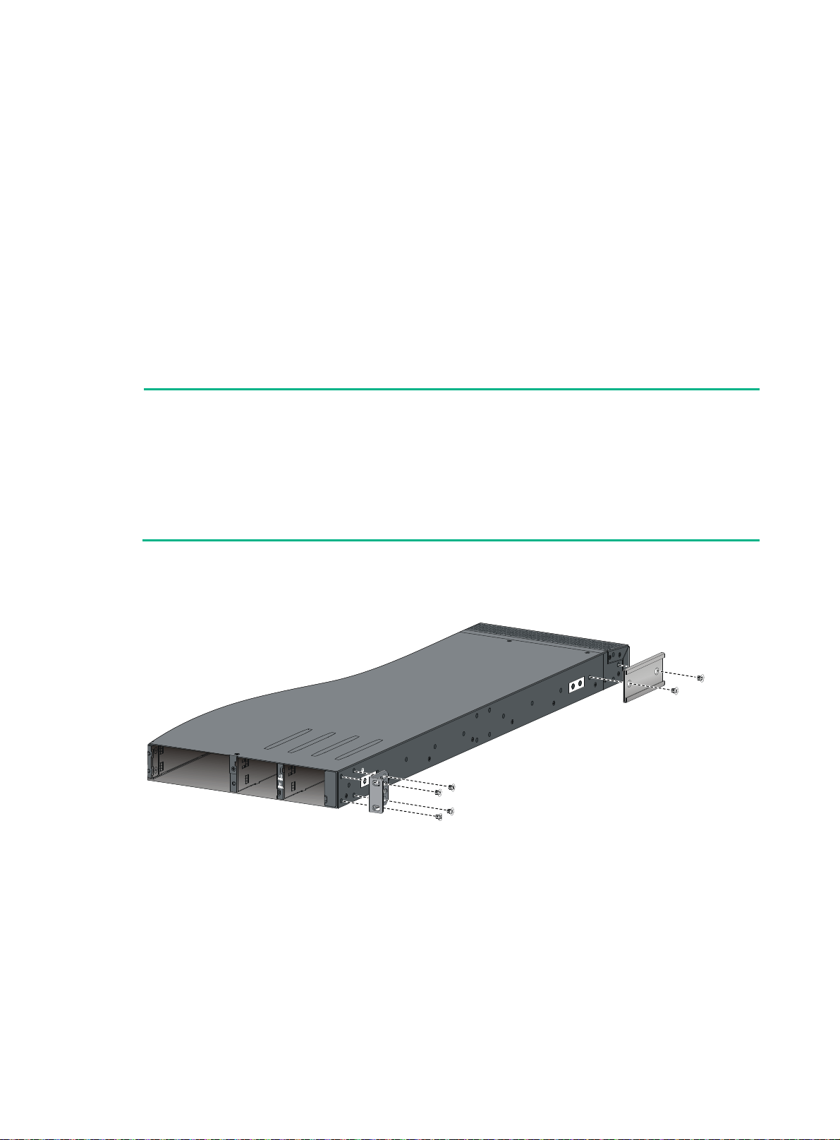
Attaching the mounting brackets and chassis rails to the chassis
1. Align the mounting brackets with the screw holes in the chassis. Use M4 screws (provided) to
attach the mounting brackets to the chassis.
{ To install the mounting brackets at the power supply-side mounting position, see Figure
10, Figure 11,
{ To install the mounting brackets at the network port-side mounting position, see Figure
13, Figure 14, and Figure 15.
lign the chassis rails with the rail mounting holes in the chassis:
2. A
{ If the mounting brackets are in the power supply-side mounting position, align the chassis
rails with the screw holes at the front of the side panels (see Figure 10, Figure 11,
and Figure 12).
{ If the mounting brackets are in the network port-side mounting position, align the chassis
rails with the screw holes at the rear of the side panels (see Figure 13, Figure 14, and Figure
15).
3. Use M4 screws (provided) to attach the chassis rails to the chassis.
NOTE:
• Secure the mounting brackets and chassis rails to both sides of the chassis in the same way.
• To install the mounting brackets at the network port-side mounting position on the HPE
5930-2Slot+2QSFP+/HPE 5930-2Slot+2QSFP+ TAA/HPE 5930-4Slot/HPE 5930-4Slot TAA
switches, use the four screw holes nearest to the network port side. To install the mounting
brackets at the power supply-side mounting position on the HPE 5930-2Slot+2QSFP+/HPE
5930-2Slot+2QSFP+ TAA/HPE 5930-4Slot/HPE 5930-4Slot TAA switches, use the four screw
holes nearest to the power supply side.
Figure 10 Attaching the mounting brackets and chassis rails to the HPE 5930-32 Q SFP+/HPE
5930-32 QSFP+ TAA switch (power supply-side mounting position for the mounting
brackets)
and Figure 12.
12
Page 17
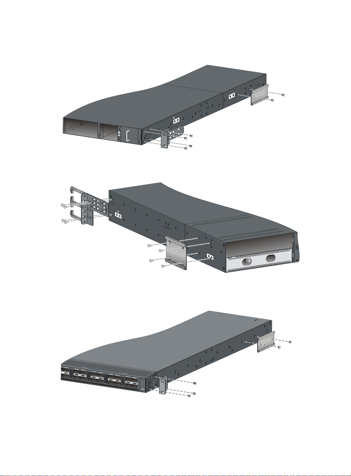
Figure 11 Attaching the mounting brackets and chassis rails to the HPE
5930-2Slot+2QSFP+/HPE 5930-2Slot+2QSFP+ TAA switch (power supply-side mounting
position for the mounting brackets)
Figure 12 Attaching the mounting brackets and chassis rails to the HPE 5930-4Slot/HPE
5930-4Slot TAA switch (power supply-side mounting position for the mounting brackets )
Figure 13 Attaching the mounting brackets and chassis rails to the HPE 5930-32 Q SFP+/HPE
5930-32 QSFP+ TAA switch (network port-side mounting position for the mounting brac kets)
13
Page 18
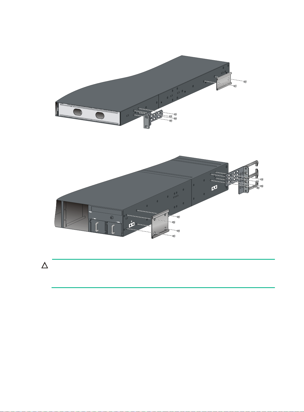
Figure 14 Attaching the mounting brackets and chassis rails to the HPE
5930-2Slot+2QSFP+/HPE 5930-2Slot+2QSFP+ TAA switch (network port-side mounting
position for the mounting brackets)
Figure 15 Attaching the mounting brackets and chassis rails to the HPE 5930-4Slot/HPE
5930-4Slot TAA switch (network port-side mounting position for the mounting brackets)
Connecting the grounding cable to the chassis
CAUTION:
Select grounding points as required. The primary grounding point and auxiliary grounding point 1 are
located on the left side panel. If you use one of these grounding points, you must connect the
grounding cable to the grounding point before you mount the switch in the rack.
As a best practice, connect the grounding cable to the primary grounding point or auxiliary grounding
point 1. The grounding cable and grounding screw that come with the switch are suitable only for
these two grounding points.
To use auxiliary grounding point 2, prepare a grounding cable yourself.
This section uses the primary grounding point on the HPE 5930-32 QSFP+/HPE 5930-32 QSFP+
TAA switch as an example.
To connect the grounding cable to a grounding point:
1. Choose a grounding point.
2. Unpack the grounding cable and grounding screws.
You can use the cable and screws shipped with the switch only for connecting to the primary
grounding point or auxiliary grounding point 1.
14
Page 19
3. Align the two-hole grounding lug at one end of the cable with the grounding holes of the
grounding point, insert the grounding screws into the holes, and tighten the screws with a
screwdriver, as shown in Figure 10.
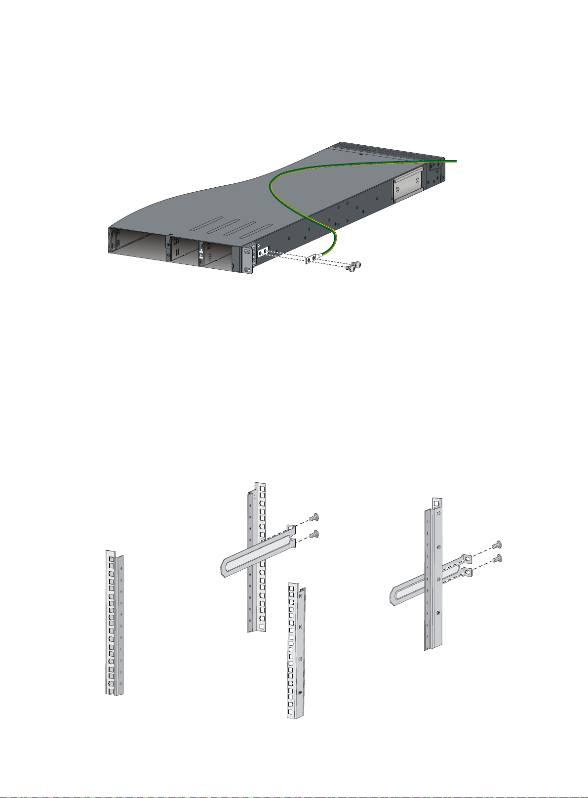
Figure 16
Attaching the grounding cable to the primary grounding point on the HPE
FlexFabric 5930-32Q switch
Attaching the slide rails to the rack
The procedures are the same for attaching 1U and 2U slide rails to the rack. This section uses the 1U
slide rails as an example.
To attach the slide rails to the rack:
1. Identify the rack attachment position for the slide rails.
2. Install cage nuts (user-supplied) in the mounting holes in the rack posts.
3. Align the screw holes in one slide rail with the cage nuts in the rack post on one side, and use
screws (user-supplied) to attach the slide rail to the rack, as shown in Figure 17.
4. Rep
eat the preceding steps to attach the other slide rail to the rack post on the other side.
Keep the two slide rails at the same height so the slide rails can attach into the chassis rails.
Figure 17 Installing the 1U slide rails
15
Page 20
Mounting the switch in the rack
This task requires two people.
To mount the switch in the rack:
1. Wear an ESD wrist strap and make sure it makes good skin contact and is reliably grounded.
2. Verify that the mounting brackets and chassis rails have been securely attached to the switch
chassis.
3. Verify that the slide rails have been correctly attached to the rear rack posts.
4. Install cage nuts (user-supplied) to the front rack posts and make sure they are at the same
level as the slide rails.
5. One person performs the following operations:
a. Supporting the bottom of the switch, aligns the chassis rails with the slide rails on the rack
posts.
b. Pushes the switch slowly to slide the chassis rails along the slide rails until the mounting
brackets are flush with the rack posts.
6. Another person uses screws (user-supplied) to attach the mounting brackets to the rack.
To secure the switch in the rack, make sure the front ends of the slide rails reach out of the
chassis rails.
The rack-mounting procedures are the same for the HPE 5930-32 QSFP+/HPE 5930-32 QSFP+
TAA/HPE 5930-2Slot+2QSFP+/HPE 5930-2Slot+2QSFP+ TAA switches. The following figures use
the HPE 5930-2Slot+2QSFP+/HPE 5930-2Slot+2QSFP+ TAA switch as an example.
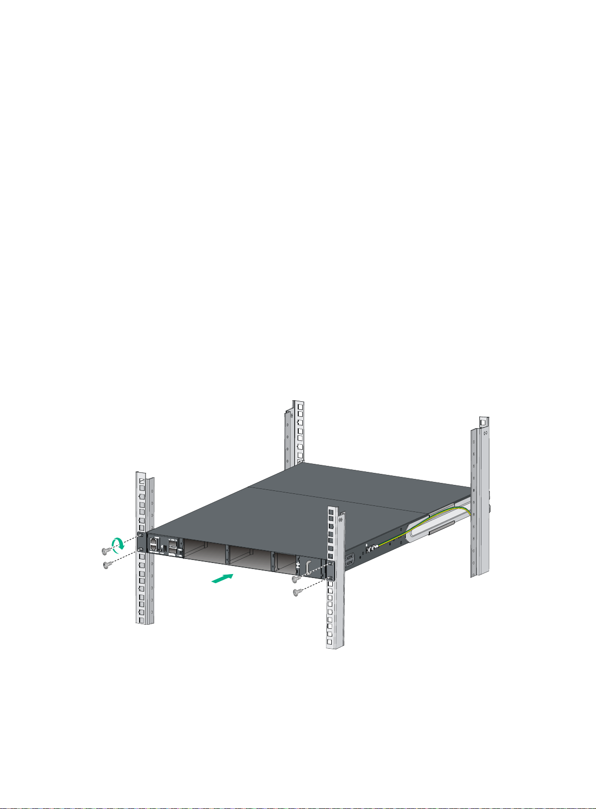
Figure 18 Mounting the HPE 5930-2Slot+2QSFP+/HPE 5930-2Slot+2QSFP+ TAA switch in the
rack (power supply-side mounting position for the mounting brackets)
16
Page 21
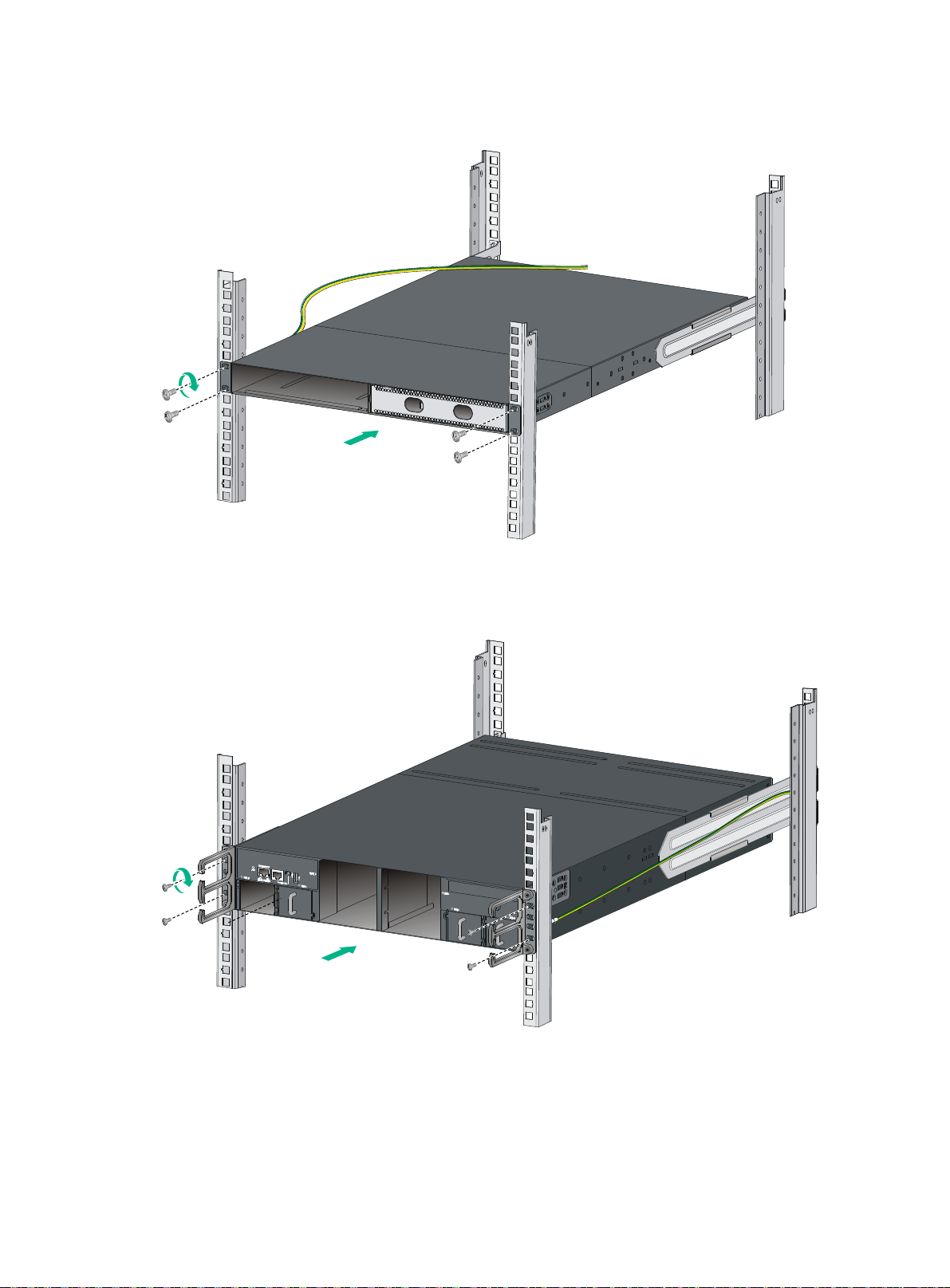
Figure 19 Mounting the HPE 5930-2Slot+2QSFP+/HPE 5930-2Slot+2QSFP+ TAA switch in the
rack (network port-side mounting position for the mounting brackets)
Figure 20 Mounting the HPE 5930-4Slot/HPE 5930-4Slot TAA switch in the rack (power
supply-side mounting position for the mounting brackets)
17
Page 22
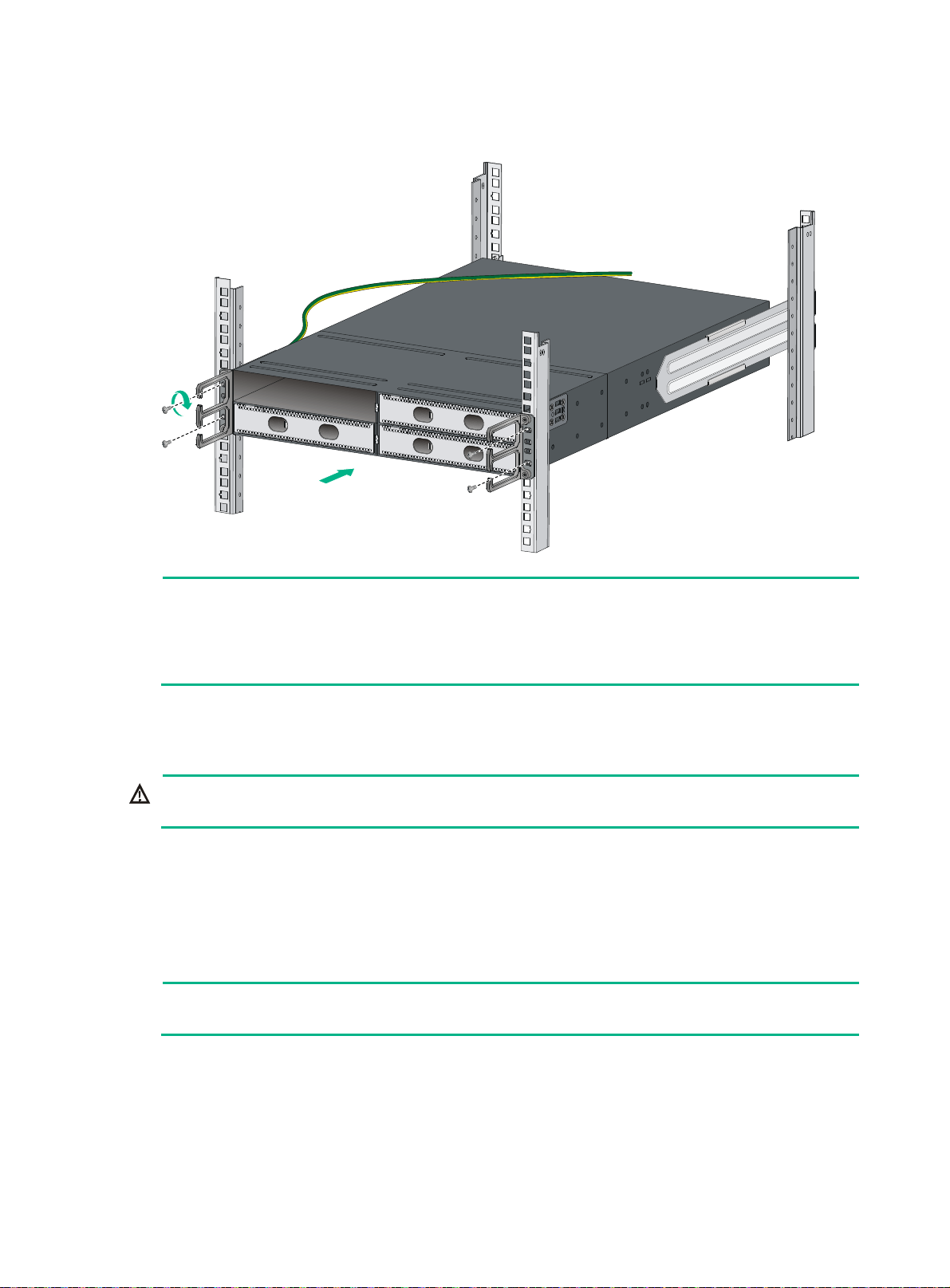
Figure 21 Mounting the HPE 5930-4Slot/HPE 5930-4Slot TAA switch in the rack (network
port-side mounting position for the mounting brackets)
NOTE:
To rack-mount the HPE 5930-4Slot/HPE 5930-4Slot TAA switch by using 2U high mounting
brackets and slide rails, use two screws and two cage nuts to attach each mounting bracket to the
rack. Determine the screw installation positions based on the distances between the square holes
on the rack posts. The screw installation positions in Figure 20 and
Grounding the switch
WARNING!
Correctly connecting the switch grounding cable is crucial to lightning protection and EMI protection.
The power input end of the switch has a noise filter, whose central ground is directly connected to the
chassis to form the chassis ground (commonly known as PGND). You must securely connect this
chassis ground to the earth so the faradism and leakage electricity can be safely released to the
earth to minimize EMI susceptibility of the switch.
You can ground a switch by using a grounding strip at the installation site or the AC power cord
connected to the switch.
NOTE:
The power and grounding terminals in this section are for illustration only.
Figure 21 are for illustration only.
18
Page 23

Grounding the switch with a grounding strip
WARNING!
Connect the grounding cable to the grounding system in the equipment room. Do not connect it to a
fire main or lightning rod.
If a grounding strip is available at the installation site, connect the grounding cable to the grounding
strip.
To connect the grounding cable:
1. Attach the two-hole grounding lug at one end of the grounding cable to a grounding point on the
switch chassis. For more information, see "Connecting the grounding cable to the chassis."
2. Remove the hex nut of a grounding post on the grounding strip.
3. Attach the ring terminal at the other end of the grounding cable to the grounding post on the
grounding strip, and secure the ring terminal to the grounding post with the hex nut.
Figure 22 Connecting the grounding cable to a grounding strip
(1) Hex nut (2) Ring terminal
(3) Grounding post (4) Grounding strip
As a best practice, connect the grounding cable to the primary grounding point or auxiliary grounding
point 1 on the switch. The grounding cable and grounding screw provided with the switch are
applicable only to these two grounding points.
To use auxiliary grounding point 2, prepare a grounding cable yourself. The connection method is the
same as connecting to the other two grounding points.
Grounding the switch by using the AC power cord
If the installation site has no grounding strips, you can ground an AC-powered switch through the
protective earth (PE) wire of the power cord, but must make sure:
• The power cord has a PE terminal.
19
Page 24

• The ground contact in the power outlet is securely connected to the ground in the power
distribution room or on the AC transformer side.
• The power cord is securely connected to the power outlet.
NOTE:
If the ground contact in the power outlet is not connected to the ground, report the problem and
reconstruct the grounding system.
Figure 23 Grounding through the PE wire of the AC power cord
1
(1) Three-wire AC power cable (2) Chassis rear panel
NOTE:
To guarantee the grounding effect, use the grounding cable provided with the switch to connect to
the grounding strip in the equipment room as long as possible.
Installing/removing a fan tray
Follow these guidelines when you install or remove a fan tray:
• Do not power on the switch when the switch has no fan trays installed.
• You must install two fan trays of the same model for the switch.
• When a fan tray fails during the switch operation and the ambient temperature is not higher than
27°C (80.6°F), replace the fan tray within 24 hours and keep the failed fan tray in position before
replacement. If the ambient temperature is higher than 27°C (80.6°F), replace the fan tray
immediately.
• Make sure all slots have a module or filler panel installed when the switch is operating.
• When two fan trays fail during switch operation:
{ Finish replacing the fan trays within 2 minutes on an HPE 5930-32 QSFP+/HPE 5930-32
QSFP+ TAA/HPE 5930-2Slot+2QSFP+/HPE 5930-2Slot+2QSFP+ TAA switch.
2
20
Page 25

{ Finish replacing the fan trays within 1 minute on an HPE 5930-4Slot/HPE 5930-4Slot TAA
switch.
Installing a fan tray
CAUTION:
To prevent damage to the fan tray or the connectors on the backplane, insert the fan tray gently. If
you encounter a hard resistance while inserting the fan tray, pull out the fan tray and insert it again.
Select appropriate fan trays as needed. For the optional fan trays and their specifications, see "Fan
trays."
Installing an LSWM1HFANSC or LSWM1HFANSCB fan tray
1. Wear an ESD wrist strap and make sure it makes good skin contact and is reliably grounded.
2. Unpack the fan tray and verify that the fan tray model is correct.
3. Grasp the handle of the fan tray with one hand and support the fan tray bottom with the other,
and slide the fan tray along the guide rails into the slot until the fan tray seats in the slot and has
a firm contact with the backplane (see callout 1 in Figure 24).
4. Fasten the captive screw on the fan tray
attached in the chassis (see callout 2 in Figure 24).
If the captive screw cannot be tightly fastened, verify the installation of the fan tray.
with a Philips screwdriver until the fan tray is securely
Figure 24 Installing an LSWM1HFANSC/LSWM1HFANSCB fan tray
Installing an LSWM1BFANSC or LSWM1BFANSCB fan tray
1. Wear an ESD wrist strap and make sure it makes good skin contact and is reliably grounded.
2. Unpack the fan tray and verify that the fan tray model is correct.
3. Orient the fan tray with the "TOP" mark on the top. Grasp the handle of the fan tray with one
hand and support the fan tray bottom with the other, and slide the fan tray along the guide rails
into the slot until the fan tray is fully seated in the slot and has a firm contact with the backplane.
21
Page 26

Figure 25 Installing an LSWM1BFANSC/LSWM1BFANSCB fan tray
Removing a fan tray
WARNING!
• Ensure electricity safety and never touch the rotating fans when you hot-swap a fan tray.
• To prevent an unbalanced fan from causing loud noise, do not touch the fans, even if they are not
rotating.
Removing an LSWM1HFANSC or LSWM1HFANSCB fan tray
1. Wear an ESD wrist strap and make sure it makes good skin contact and is reliably grounded.
2. Loosen the captive screw of the fan tray with a Philips screwdriver until it is fully disengaged
from the switch chassis.
3. Grasp the handle of the fan tray with one hand and pull the fan tray part way out of the slot.
Support the fan tray bottom with the other hand, and pull the fan tray slowly along the guide rails
out of the slot.
4. Place the removed fan tray in an antistatic bag.
Removing an LSWM1BFANSC or LSWM1BFANSC fan tray
1. Wear an ESD wrist strap and make sure it makes good skin contact and is reliably grounded.
2. Grasp the fan tray handle with one hand to pull the fan tray part way out. Support the fan tray
bottom with the other and pull out the fan tray slowly along the guide rails.
3. Place the removed fan tray in an antistatic bag.
22
Page 27

Figure 26 Removing an LSWM1BFANSC/LSWM1BFANSCB fan tray
Installing/removing a power supply
WARNING!
• In power redundancy mode, you can replace a power supply without powering off the switch but
must strictly follow the installation and procedures in Figure 27 and
injury or damage to the switch.
• Provide a separate circuit breaker for each power supply.
The switch comes with the power supply slots empty and filler panels for the power supply slots as
accessories.
For more information about the power supplies available for the switches, see "Power supplies."
Figure 27
Figure 28 Removal procedure
Installation procedure
Figure 28 to avoid any bodily
23
Page 28

f
Installing a power supply
CAUTION:
• Do not install AC and DC power supplies on the same switch.
• Follow the forward inertia of the power supply when inserting it into the chassis, and make sure
the power supply has firm contact with the connectors on the backplane.
• To prevent damage to the connectors inside the switch chassis, insert the power supply gently. I
you encounter a hard resistance while inserting the power supply, pull out the power supply and
insert it again.
• Install filler panels in the empty power supply slots for good ventilation of the switch.
The power supply installation procedures are the same for the HPE FlexFabric 5930 switches. This
section uses the HPE 5930-32 QSFP+/HPE 5930-32 QSFP+ TAA switch as an example.
To install a power supply:
1. Wear an ESD wrist strap and make sure it makes good skin contact and is reliably grounded.
2. Unpack the power supply and verify that the power supply model is correct.
3. Correctly orient the power supply with the power supply slot (see Figure 29), gra
of the power supply with one hand and support its bottom with the other, and slide the power
supply slowly along the guide rails into the slot.
The slot is foolproof. If you cannot insert the power supply into the slot, re-orient the power
supply rather than use excessive force to push it in.
sp the handle
Figure 29 Installing a power supply
Figure 30 Installing a filler panel in a power supply slot
24
Page 29

Removing a power supply
CAUTION:
• When an HPE 5930-32 QSFP+/HPE 5930-32 QSFP+ TAA/HPE 5930-2Slot+2QSFP+/HPE
5930-2Slot+2QSFP+ TAA switch has two power supplies in 1+1 redundancy mode, removing
one power supply does not affect the operation of the switch. When the switch has only one
power supply installed, removing the power supply powers off the switch.
• When an HPE 5930-4Slot/HPE 5930-4Slot TAA switch has four power supplies in 2+2
redundancy mode, removing one or two power supplies does not affect the operation of the
switch. When the switch has only two power supply installed, removing a power supply might
power off the switch or cause power insufficiency.
• The power cord color code scheme in Figure 31 is for
your country or region might use a different color scheme. When you connect the power cord,
always identify the polarity symbol on its wires.
The power supply removing procedures are the same for the HPE FlexFabric 5930 switches. This
section uses the HPE 5930-32 QSFP+/HPE 5930-32 QSFP+ TAA switch as an example:
To remove a power supply:
1. Wear an ESD wrist strap and make sure it makes good skin contact and is reliably grounded.
2. Squeeze the tabs on the power cord connector with your thumb and forefinger, and pull the
connector out to remove the power cord, as shown in Figure 31.
3. Hold the h
right with your thumb, and pull the power supply part way out of the slot, as shown in Figure 32.
4. Suppo
other hand.
5. Put away the removed power supply in an antistatic bag for future use.
andle on the power supply with one hand, pivot the latch on the power supply to the
rting the power supply bottom with one hand, slowly pull the power supply out with the
illustration only. The cable delivered for
25
Page 30

Figure 31 Removing the DC power cord
(1) Press the tabs on the power cord connector with your thumb and
forefinger
(2) Pull the power cord connector out
Figure 32 Removing the power supply
(1) Pivot the latch to the right with your thumb (2) Pull the power supply out
Connecting the power cord
WARNING!
Provide a circuit breaker for each power input. When you connect a power cord, make sure the
circuit breaker is switched off.
26
Page 31

Connecting the 650W AC power supply
1. Insert the female connector of the AC power cord supplied with the power supply into the power
receptacle on the power supply.
2. Use a cable tie to secure the power cord to the handle of the power supply, as shown in Figure
33.
3. Con
Figure 33 Connecting the 650W AC power supply
nect the other end of the power cord to an AC power outlet.
(1) Cable tie
(2) Tighten the cable tie to secure the power cord to the handle of the power supply
Connecting the 650W DC power supply
CAUTION:
The power cord color code scheme in Figure 34 is for
country or region might use a different color scheme. When you connect the power cord, always
identify the polarity symbol on its wires.
To connect the 650W DC power supply:
1. Unpack the DC power cord, identify the plug for connecting to the power supply, orient the plug
with the power receptacle on the power supply, and insert the plug into the receptacle
(see Figure 34).
ceptacle is foolproof. If you cannot insert the plug into the receptacle, re-orient the plug
The re
rather than use excessive force to push it in.
2. Use a cable tie to secure the power cord to the handle of the power supply, as shown in Figure
33.
3. Con
nect the other ends of the wires to the DC power source wiring terminals, with the negative
wire (– or L–) to the negative terminal (–) and the positive wire (+ or M/N) to the positive terminal
(+).
illustration only. The cable delivered for your
27
Page 32

Figure 34 Connecting the 650W DC power supply
Installing/Removing an interface module
CAUTION:
When you install or remove an interface module, follow these guidelines:
• Never touch the components on the interface module surface.
• Do not use excessive force.
The HPE 5930-2Slot+2QSFP+/HPE 5930-2Slot+2QSFP+ TAA switch provides two interface module
slots. The HPE 5930-4Slot/HPE 5930-4Slot TAA switch provides four interface module slots. For the
available interface modules, see "Appendix B FRUs and compatibility matrixes."
The interfa
ce module installation and removal procedures are the same. This section uses the
LSWM18QC interface module as an example.
Installing an interface module
1. Wear an ESD wrist strap and make sure the wrist strap makes good skin contact and is reliably
grounded.
2. (Optional.) If the target interface module slot has a filler panel installed, remove the filler
panel. Figure 35 u
an example.
To remove a filler panel from an interface module slot:
a. Use your thumb and forefinger to hold the filler panel through the two holes.
b. Push right the metal tab in the left hole and pull out the filler panel along the guide rails.
Figure 35 Removing a filler panel from the interface module slot
ses the HPE 5930-2Slot+2QSFP+/HPE 5930-2Slot+2QSFP+ TAA switch as
Keep the removed filler panel secure for future use.
3. Unpack the interface module.
28
Page 33

Figure 36 LSWM18QC interface module
(1) Ejector lever (2) Latch
4. Press the latch on the interface module to release the ejector lever.
5. Insert the interface module slowly into the slot along the guide rails, as shown by callout 1
in Figure 37.
6. Rotate in
ward the ejector lever as shown by callout 2 in Figure 37 until the latch
locks the
ejector lever in place.
Figure 37 Installing an LSWM18QC interface module
2
Removing an interface module
CAUTION:
• Before you remove an interface module, remove the cable from it to avoid cable damage.
• After removing an interface module, if no new interface module is to be installed, install the filler
panel as soon as possible to prevent dust and ensure good ventilation in the device.
To remove an interface module:
1. Prepare an anti-static bag.
2. Wear an ESD wrist strap and make sure the wrist strap makes good skin contact and is reliably
grounded.
3. Press the latch to release the ejector lever
4. Rotate outward the ejector lever as shown by callout 1 in Figure 38.
5. Pull out the interface m
in Figure 38.
6. Place the re
moved interface module in the anti-static bag.
1
odule slowly out of the interface module slot, as shown by callout 2
29
Page 34

Figure 38 Removing an LSWM18QC interface module
Verifying the installation
After you complete the installation, verify the following information:
• There is enough space for heat dissipation around the switch, and the rack is stable.
• The grounding cable is securely connected.
• The correct power source is used.
• The power cords are correctly connected.
• All the interface cables are cabled indoors. If any cable is routed outdoors, verify that the socket
strip with lightning protection and lightning arresters for network ports have been correctly
connected.
30
Page 35

Accessing the switch for the first time
Setting up the configuration environment
The switch supports the following ways to connect the configuration terminal:
• Through the console port by using the serial console cable
The switch comes with the serial console cable. This way is preferred.
• Through the USB mini console port by using the user-supplied USB mini console cable
Do not use the two ways together on the same switch.
The example uses a console cable to connect a console terminal (PC) to the serial console port on
the switch.
Figure 39 Connecting the serial console port to a terminal
Connecting the console cable
Serial console cable
A serial console cable is an 8-core cable, with a crimped RJ-45 connector at one end for connecting
to the serial console port of the switch, and a DB-9 female connector at the other end for connecting
to the serial port on the console terminal.
Figure 40 Serial console cable
A side
Pin 9
A
Pin 1
Main label
8
1
B side
B
31
Page 36

Table 7 Serial console cable pinout
RJ-45 Signal DB-9 Signal
1 RTS 8 CTS
2 DTR 6 DSR
3 TXD 2 RXD
4 SG 5 SG
5 SG 5 SG
6 RXD 3 TXD
7 DSR 4 DTR
8 CTS 7 RTS
USB mini console cable
A USB mini console cable has a USB mini-Type B connector at one end to connect to the USB mini
console port of the switch, and a standard USB Type A connector at the other end to connect to the
USB port on the configuration terminal.
Connection procedure
To connect a terminal (for example, a PC) to the switch by using the serial console cable:
1. Plug the DB-9 female connector of the serial console cable to the serial port of the PC.
2. Connect the RJ-45 connector to the serial console port of the switch.
NOTE:
• Identify the mark on the console port and make sure you are connecting to the correct port.
• The serial ports on PCs do not support hot swapping. If the switch has been powered on, connect
the serial console cable to the PC before connecting to the switch, and when you disconnect the
cable, first disconnect from the switch.
To connect to the configuration terminal through the USB mini console cable:
1. Connect the standard USB Type A connector to the USB port of the configuration terminal.
2. Connect the USB mini Type B connector to the USB mini console port of the switch.
3. Click the following link, or copy it to the address bar on the browser to log in to download page
of the USB console driver, and download the driver.
http://www.exar.com/connectivity/uart-and-bridging-solutions/usb-uarts/xr21v1410
Select a driver program according to the operating system you use:
{ XR21V1410_XR21B1411_Windows_Ver1840_x86_Installer.EXE—32-bit operating
system.
{ XR21V1410_XR21B1411_Windows_Ver1840_x64_Installer.EXE—64-bit operating
system.
4. Click Next on the installation wizard.
32
Page 37

Figure 41 Device Driver Installation Wizard
5. Click Continue Anyway if the following dialog box appears.
Figure 42 Software Installation
6. Click Finish.
33
Page 38

Figure 43 Completing the device driver installation wizard
Setting terminal parameters
To configure and manage the switch through the console port, you must run a terminal emulator
program, HyperTerminal or PuTTY, on your configuration terminal. You can use the emulator
program to connect a network device, a Telnet site, or an SSH site. For more information about the
terminal emulator programs, see the user guides for these programs
The following are the required terminal settings:
• Bits per second—9600
• Data bits—8
• Stop bits—1
• Parity—None
• Flow control—None
Powering on the switch
Before powering on the switch, verify that the following conditions are met:
• The power cord is correctly connected.
• The input power voltage meets the requirement of the switch.
• The console cable is correctly connected.
• The configuration terminal (a PC, for example) has started, and its serial port settings are
consistent with the console port settings on the switch.
Power on the switch. During the startup process, you can access Boot ROM menus to perform tasks
such as software upgrade and file management. The Boot ROM interface and menu options differ
34
Page 39

with software versions. For more information about Boot ROM menu options, see the
software-matching release notes for the device.
After the startup completes, you can access the CLI to configure the switch.
For more information about the configuration commands and CLI, see HPE FlexFabric 5930 Switch
Series Configuration Guide and HPE FlexFabric 5930 Switch Series Command References.
35
Page 40

Setting up an IRF fabric
You can use HPE IRF technology to connect and virtualize HPE FlexFabric 5930 switches into a
large virtual switch called an "IRF fabric" for flattened network topology, and high availability,
scalability, and manageability.
To set up IRF links between two switches, use the 10-GE or 40-GE ports.
IRF fabric setup flowchart
Figure 44 IRF fabric setup flowchart
To set up an IRF fabric:
Step Description
Plan the installation site and IRF fabric setup parameters:
• Planning IRF fabric size and the installation site
1. Plan IRF fabric setup.
• Identifying the master switch and p
• Planning IRF topology and connections
• Identifying physical IRF ports on the member switches
• Planning the cabling scheme
36
lanning IRF member IDs
Page 41

r
Step Description
2. Install IRF member
switches.
3. Connect ground wires
and power cords.
4. Power on the
switches.
5. Configure basic IRF
settings.
6. Connect the physical
IRF ports.
See "Installing the switch in a 19-inch rack".
See "Grounding the switch" a
N/A
See FlexFabric 5930 Switch Series IRF Configuration Guide.
Connect the physical IRF ports on switches. Use SFP+/QSFP+ transceiver
modules and fibers for long-distance connection. Use twisted pair cables or
SFP+/QSFP+ network cables for short-distance connection.
All switches except the master switch automatically reboot, and the IRF fabric
is established.
nd "Connecting the power cord."
Planning IRF fabric setup
This section describes issues that an IRF fabric setup plan must cover.
Planning IRF fabric size and the installation site
Choose switch models and identify the number of required IRF member switches, depending on the
user density and upstream bandwidth requirements. The switching capacity of an IRF fabric equals
the total switching capacities of all member switches.
Plan the installation site depending on your network solution as follows:
• Place all IRF member switches in one rack for centralized high-density access.
• Distribute the IRF member switches in different racks to implement the top-of-rack (ToR) access
solution for a data center.
As your business grows, you can plug HPE FlexFabric 5930 switches into the IRF fabric to increase
the switching capacity without any topology change or replacement.
Identifying the master switch and planning IRF member IDs
Determine which switch you want to use as the master for managing all member switches in the IRF
fabric. An IRF fabric has only one master switch. You configure and manage all member switches in
the IRF fabric at the command line interface of the master switch.
NOTE:
IRF member switches will automatically elect a master. You can affect the election result by
assigning a high member priority to the intended master switch. For more information about maste
election, see HPE FlexFabric 5930 Switch Series IRF Configuration Guide.
Prepare an IRF member ID assignment scheme. An IRF fabric uses member IDs to uniquely identify
and manage its members, and you must assign each IRF member switch a unique member ID.
37
Page 42

Planning IRF topology and connections
You can create an IRF fabric in daisy chain topology, or more reliably, ring topology. In ring topology,
the failure of one IRF link does not cause the IRF fabric to split as in daisy chain topology. Rather, the
IRF fabric changes to a daisy chain topology without interrupting network services.
You connect the IRF member switches through IRF ports, the logical interfaces for the connections
between IRF member switches. Each IRF member switch has two IRF ports: IRF-port 1 and IRF-port
2. To use an IRF port, you must bind at least one physical port to it.
When connecting two neighboring IRF member switches, you must connect the physical ports of
IRF-port 1 on one switch to the physical ports of IRF-port 2 on the other switch.
The IRF port connections in the two figures are for illustration only, and more connection methods
are available.
Figure 45 IRF fabric in daisy chain topology
1
2
3
IRF-port1IRF-port1
IRF-port2 IRF-port2
1 2 3
Figure 46 IRF fabric in ring topology
1
2
3
IRF-port1
IRF-port2
IRF-port1
2 3
IRF-port2
1
IRF-port1
IRF-port2
You can provide the following IRF physical connections between HPE FlexFabric 5930 switches:
• 10-GE IRF physical connection by connecting 1/10-GE Ethernet ports or SFP+ ports.
• 40-GE IRF physical connection by connecting QSFP+ ports.
• IRF physical connection by using a 40G QSFP+ to SFP+ network cable to connect a QSFP+
port and four SFP+ ports.
You can bind several ports to an IRF port for increased bandwidth and availability.
38
Page 43

Identifying physical IRF ports on the member switches
Identify the 1/10-GE Ethernet ports, SFP+ ports, and QSFP+ ports to be used for IRF connections on
the member switches according to your topology and connection scheme.
All the 1/10-GE Ethernet ports, SFP+ ports, and QSFP+ ports on the HPE FlexFabric 5930 switch
can be used for IRF connections.
Planning the cabling scheme
You can use twisted pair cables, SFP+/QSFP+ network cables, or SFP+/QSFP+ transceiver
modules and optical fibers to connect the switches for IRF connections. If the IRF member switches
are far away from one another, choose the SFP+/QSFP+ transceiver modules and optical fibers. If
the IRF member switches are all in one equipment room, choose twisted pair cables or
SFP+/QSFP+ cables. For more information about available transceiver modules and cables, see
"Appendix C Ports and LEDs."
The followin
Packard Enterprise, and all these schemes use a ring topology.
g subsections describe several IRF connection schemes recommended by Hewlett
Connecting the IRF member switches in one rack
Figure 47 shows an example for connecting four IRF member switches in a rack by using QSFP+
network cables and QSFP+ transceiver modules and optical fibers. The switches in the ring topology
(see Figure 48) are in the same order a
Figure 47 Connecting the switches in one rack
Figure 48 IRF fabric topology
s connected in the rack.
Connecting the IRF member switches in a ToR solution
You can install IRF member switches in different racks side by side to deploy a top of rack (ToR)
solution.
39
Page 44

Figure 49 shows an example for connecting four top of rack IRF member switches by using QSFP+
network cables and QSFP+ transceiver modules and optical fibers. The topology is the same
as Figure 48.
Figure 49
ToR cabling
Configuring basic IRF settings
After you install the IRF member switches, power on the switches, and log in to each IRF member
switch (see HPE FlexFabric 5930 Switch Series Fundamentals Configuration Guide) to configure
their member IDs, member priorities, and IRF port bindings.
Follow these guidelines when you configure the switches:
• Assign the master switch higher member priority than any other switch.
• Bind physical ports to IRF port 1 on one switch and to IRF port 2 on the other switch. You
perform IRF port binding before or after connecting IRF physical ports depending on the
software release.
• Execute the display irf configuration command to verify the basic IRF settings.
For more information about configuring basic IRF settings, see HPE FlexFabric 5930 Switch Series
IRF Configuration Guide.
Connecting the physical IRF ports
CAUTION:
Wear an ESD wrist strap when you connect cables or transceiver modules and optical fibers. For
more information, see the installation guide for the transceiver modules.
Use cables or transceiver modules and optical fibers to connect the IRF member switches as
planned.
Accessing the IRF fabric to verify the configuration
To verify the basic functionality of the IRF fabric after you finish configuring basic IRF settings and
connecting IRF ports:
1. Log in to the IRF fabric through the console port of any member switch.
2. Create a Layer 3 interface, assign it an IP address, and make sure the IRF fabric and the
remote network management station can reach each other.
3. Use Telnet, Web, or SNMP to access the IRF fabric from the network management station.
(See HPE FlexFabric 5930 Switch Series Fundamentals Configuration Guide.)
4. Verify that you can manage all member switches as if they were one node.
5. Display the running status of the IRF fabric by using the commands in Table 8.
40
Page 45

r
Table 8 Displaying and maintaining IRF configuration and running status
Task Command
Display information about the IRF fabric.
Display all members' IRF configurations.
Display IRF fabric topology information.
NOTE:
display irf
display irf configuration
display irf topology
To avoid IP address collision and network problems, configure at least one multi-active detection
(MAD) mechanism to detect the presence of multiple identical IRF fabrics and handle collisions. Fo
more information about MAD detection, see HPE FlexFabric 5930 Switch Series IRF Configuration
Guide.
41
Page 46

Maintenance and troubleshooting
Power supply failure
You can use the LEDs on the power supply to identify a power supply failure. For more information
about the LEDs on a power supply, see HPE A58x0AF 650W AC (JC680A) & 650W DC (JC681A)
Power Supplies User Guide or HPE FlexFabric Switch 650W 48V Hot Plug NEBS Compliant DC
Power Supply (JH336A) User Guide.
The LEDs on the power supply are steady green (active) or flashing green (standby) while the power
supply system is correctly operating. If the LEDs behave in any other way, verify the following items:
• The switch power cord is correctly connected.
• The power source meets the requirement.
• The operating temperature of the switch is in the normal range and the power supply has good
ventilation.
If the problem persists, contact Hewlett Packard Enterprise Support.
To replace a power supply, see "Installing/removing a power supply."
Fan tray failure
When an LSWM1HFANSC or LSWM1HFANSCB fan tray has problems, the system status LED on
the switch is steady red and the system outputs alarm messages.
When an LSWM1BFANSC or LSWM1BFANSCB fan tray has problems, the Alarm LED on the fan
tray is steady yellow and the system outputs alarm messages.
To replace a failed fan tray, see "Installing/removing a fan tray."
Follow the
• Do not power on the switch when the switch has no fan trays installed.
• You must install two fan trays of the same model for the switch.
• When a fan tray fails during the switch operation and the ambient temperature is not higher than
• Make sure all slots have a module or filler panel installed when the switch is operating.
• When two fan trays fail during the switch operation:
se guidelines when you install or remove a fan tray:
27°C (80.6°F), replace the fan tray within 24 hours and keep the failed fan tray in position before
replacement. If the ambient temperature is higher than 27°C (80.6°F), replace the fan tray
immediately.
{ Finish replacing the fan trays within 2 minutes on an HPE 5930-32 QSFP+/HPE 5930-32
QSFP+ TAA/HPE 5930-2Slot+2QSFP+/HPE 5930-2Slot+2QSFP+ TAA switch.
{ Finish replacing the fan trays within 1 minute on an HPE 5930-4Slot/HPE 5930-4Slot TAA
switch.
Configuration terminal problems
If the configuration environment setup is correct, the configuration terminal displays booting
information when the switch is powered on. If the setup is incorrect, the configuration terminal
displays nothing or garbled text.
42
Page 47

No terminal display
The configuration terminal has no display when the switch is powered on.
To resolve the problem:
1. Verify that the power system is operating correctly.
2. Verify that the console cable has been connected correctly and no fault occurs on the console
cable.
3. Verify that the following settings are configured for the terminal:
{ Baud rate—9600.
{ Data bits—8.
{ Stop bits—1.
{ Parity—None.
{ Flow control—None.
4. If the problem persists, contact Hewlett Packard Enterprise Support.
Garbled terminal display
The configuration terminal displays garbled text.
To resolve the problem:
1. Verify that the following settings are configured for the terminal:
{ Baud rate—9600.
{ Data bits—8.
{ Stop bits—1.
{ Parity—None.
{ Flow control—None.
2. If the problem persists, contact Hewlett Packard Enterprise Support.
43
Page 48

Appendix A Chassis views and technical specifications
Chassis views
HPE 5930-32 QSFP+/HPE 5930-32 QSFP+ TAA
Figure 50 Front panel
(1) QSFP+ port (2) QSFP+ port LED
(3) System status LED (SYS)
Figure 51 Rear panel
(1) Grounding screw (auxiliary grounding point 2) (2) Management Ethernet port
(3) Serial console port (4) Fan tray slot 1
(5) Fan tray slot 2 (6) Power supply slot 1
(7) Power supply slot 2 (8) USB port
(9) USB mini console port (10) LINK LED for the management Ethernet port
(11) ACT LED for the management Ethernet port
The HPE 5930-32 QSFP+/HPE 5930-32 QSFP+ TAA switch comes with the two power supply slots
empty and a filler panel as an accessory. You can install one or two power supplies for the switch as
needed. In Figure 51, two 650
information about installing and removing power supplies, see "Installing/removing a power supply."
The HPE 5
You must install two fan trays of the same model for the switch. In Figure 51, two LSWM1HF
fan trays are installed in the fan tray slots. For more information about installing and removing fan
trays, see "Installing/removing a fan tray."
930-32 QSFP+/HPE 5930-32 QSFP+ TAA switch comes with the two fan tray slots empty.
W AC power supplies are installed in the power supply slots. For more
ANSC
44
Page 49

Figure 52 Left side panel
1 2
(1) Primary grounding point (2) Auxiliary grounding point 1
HPE 5930-2Slot+2QSFP+/HPE 5930-2Slot+2QSFP+ TAA
Figure 53 Front panel
(1) Interface module slot 1 (2) Interface module slot 2
Figure 54 Rear panel
(1) USB mini console port (2) USB port
(3) Fan tray slot 1 (4) Fan tray slot 2
(5) Power supply slot 1 (6) Power supply slot 2
(7) QSFP+ port (8) QSFP+ port LED
(9) System status LED (SYS) (10) LINK/ACT LED for the management Ethernet port
(11) Management Ethernet port (12) Serial console port
The HPE 5930-2Slot+2QSFP+/HPE 5930-2Slot+2QSFP+ TAA switch comes with interface module
slot 1 empty and interface module 2 installed with a filler panel. You can install one or two interface
modules for the switch as needed. In Figure 53, two LSWM1
8QC interface modules are installed in
the interface module slots. For more information about installing and removing interface modules,
see "Installing/Removing an interface module."
The HPE 5930-2Slot+2QSFP+/HPE 5930-2Slot+2QSFP+ TAA switch comes with the two power
supplies empty and a filler panel as an accessory. You can install one or two power supplies for the
switch as needed. In Figure 54, two 650
W AC power supplies are installed in the power supply slots.
For more information about installing and removing power supplies, "Installing/removing a power
ply."
sup
45
Page 50

The HPE 5930-2Slot+2QSFP+/HPE 5930-2Slot+2QSFP+ TAA switch comes with the two fan tray
slots empty. You must install two fan trays of the same model for the switch. In Figure 54, two
LSWM1HFANSC fan trays are installed in the fan tray slots. For more information about installing
and removing fan trays, "Installing/removing a fan tray."
Figure 55
(1) Primary grounding point (2) Auxiliary grounding point 1
Left side panel
HPE 5930-4Slot/HPE 5930-4Slot TAA
Figure 56 Front panel
1
2
(1) Interface module slot 1 (2) Interface module slot 2
(3) Interface module slot 4 (4) Interface module slot 3
34
46
Page 51

Figure 57 Rear panel
41 2 3 5 6 7 8
91011121314
(1) System status LED (SYS) (2) Management Ethernet port
(3) Serial console port (4) USB mini console port
(5) USB port (6) Fan tray slot 1
(7) Fan tray slot 2 (8) Grounding screw (auxiliary grounding point 2)
(9) Power supply slot 4 (10) Power supply slot 3
(11) Power supply slot 2 (12) LINK LED for the management Ethernet port
(13) ACT LED for the management Ethernet port (14) Power supply slot 1
The HPE 5930-4Slot/HPE 5930-4Slot TAA switch comes with a filler panel in all interface module
slots except slot 1. You can install one to four interface modules for the switch as needed. In Figure
56, the LSWM18Q
C interface modules are installed in the interface module slots. For more
information about installing and removing interface modules, see "Installing/Removing an interface
module."
The HPE 5930-4Slot/HPE 5930-4Slot TAA switch comes with the four power supply slot empty and
three filler panels as accessories. You can install two to four power supplies for the switch as needed.
In Figure 57,
information about installing and removing power supplies, "Installing/removing a power supply."
two 650W AC power supplies are installed in the power supply slots. For more
The HPE 5930-4Slot/HPE 5930-4Slot TAA switch comes with the two fan tray slots empty. You must
install two fan trays of the same model for the switch. In Figure 57,
two LSWM1HFANSC fan trays
are installed in the fan tray slots. For more information about installing and removing fan trays,
"Installing/removing a fan tray."
Figure 58
(1) Primary grounding point (2) Auxiliary grounding point 1
Left side panel
1 2
47
Page 52

Technical specifications
Table 9 Technical specifications
HPE 5930-32
Item
QSFP+/HPE 5930-32
QSFP+ TAA
Dimensions (H
× W × D)
Weight ≤ 13 kg (28.66 lb) ≤ 16 kg (35.27 lb) ≤ 27 kg (59.52 lb)
Console ports
Management
Ethernet ports
USB ports 1 1 1
QSFP+ ports 32 2 N/A
Interface
module slots
Fan tray slots 2 2 2
Power supply
slots
AC-input
voltage
DC-input
voltage
Minimum power
consumption
Maximum
power
consumption
43.6 × 440 × 660 mm (1.72
× 17.32 × 25.98 in)
• 1 × USB Mini console
port
• 1 × serial console port
1 1 1
N/A 2 4
2 2 4
• Rated voltage: 100 VAC to 240 VAC @ 50 or 60 Hz
• Max voltage: 90 VAC to 264 VAC @ 47 to 63 Hz
• Rated voltage: –40 VDC to –60 VDC
• Max voltage: –40 VDC to –72 VDC
• Single AC input: 175 W
• Dual AC inputs: 190 W
• Single DC input: 172 W
• Dual DC inputs: 183 W
• Single AC input: 394 W
• Dual AC inputs: 409 W
• Single DC input: 398 W
• Dual DC inputs: 399 W
HPE
5930-2Slot+2QSFP+/HP
E 5930-2Slot+2QSFP+
TAA
44.2 × 440 × 660 mm (1.74
× 17.32 × 25.98 in)
• 1 × USB Mini console
port
• 1 × serial console port
• Single AC input: 105 W
• Dual AC inputs: 116 W
• Single DC input: 98 W
• Dual DC inputs: 115 W
• Single AC input: 504 W
• Dual AC inputs: 515 W
• Single DC input: 508 W
• Dual DC inputs: 508 W
HPE 5930-4Slot/HPE
5930-4Slot TAA
88.1 × 440 × 660 mm (3.47
× 17.32 × 25.98 in)
• 1 × USB Mini console
port
• 1 × serial console port
• Dual AC inputs: 139
W
• Triple AC inputs: 156
W
• Quadruple AC inputs:
172 W
• Dual DC inputs: 145
W
• Triple DC inputs: 160
W
• Quadruple DC inputs:
171 W
• Dual AC inputs: 892
W
• Triple AC inputs: 902
W
• Quadruple AC inputs:
921 W
• Dual DC inputs: 888
W
• Triple DC inputs: 888
W
• Quadruple DC inputs:
888 W
48
Page 53

Item
Chassis
leakage current
compliance
Melting current
of power supply
fuse
Operating
temperature
Operating
humidity
Fire resistance
compliance
HPE 5930-32
QSFP+/HPE 5930-32
QSFP+ TAA
UL60950-1, EN60950-1, IEC60950-1, GB4943
• 10 A @ 250 VAC
• 30 A @ 250 VDC
0°C to 45°C (32°F to 113°F)
10% to 90%, noncondensing
UL60950-1, EN60950-1, IEC60950-1, GB4943
HPE
5930-2Slot+2QSFP+/HP
E 5930-2Slot+2QSFP+
TAA
HPE 5930-4Slot/HPE
5930-4Slot TAA
49
Page 54

Appendix B FRUs and compatibility matrixes
Table 10 Compatibility matrix between the FRUs and HPE FlexFabric 5930 switches
HPE 5930-32
FRUs
Power supplies
650W AC Yes Yes Yes
650W DC Yes Yes Yes
Fan trays
LSWM1HFANSC Yes Yes No
LSWM1HFANSCB Yes Yes No
LSWM1BFANSC No No Yes
LSWM1BFANSCB No No Yes
Interface modules
LSWM18QC No Yes Yes
LSWM124XGT2Q No Yes Yes
LSWM124XG2Q No Yes Yes
LSWM124XG2QL No Yes Yes
LSWM124XG2QFC No Yes Yes
QSFP+/HPE
5930-32 QSFP+
TAA
HPE
5930-2Slot+2QSFP+/HPE
5930-2Slot+2QSFP+ TAA
HPE
5930-4Slot/HPE
5930-4Slot TAA
IMPORTANT:
• The HPE 5930-32 QSFP+/HPE 5930-32 QSFP+ TAA/HPE 5930-2Slot+2QSFP+/HPE
5930-2Slot+2QSFP+ TAA switches can operate correctly with only one power supply. You can
install two power supplies on the switches for 1+1 redundancy.
• The HPE 5930-4Slot/HPE 5930-4Slot TAA switch can operate correctly with two power supplies.
You can install four power supplies on the switches for 2+2 redundancy.
• You must install two fan trays of the same model for the switch.
Power supplies
CAUTION:
When the switch has power supplies in redundancy, you can replace a power supply without
powering off the switch. Make sure the power supply to be replaced is powered off before you
replace it.
50
Page 55

Table 11 Power supply specifications
Power supply Specifications Remarks
650W AC
650W DC
Fan trays
Table 12 Fan tray specifications
Item Specifications
• Rated input voltage:
100 VAC to 240 VAC @ 50 Hz or 60 Hz
• Max input voltage:
90 VAC to 264 VAC @ 47 Hz to 63 Hz
• Max output power:
650 W
• Rated input voltage:
–40 VDC to –60 VDC
• Max input voltage:
–40 VDC to –72 VDC
• Max output power:
650 W
For more information about the
power supplies, see HPE A58x0AF
650W AC (JC680A) & 650W DC
(JC681A) Power Supplies User
Guide or HPE FlexFabric Switch
650W 48V Hot Plug NEBS
Compliant DC Power Supply
(JH336A) User Guide.
LSWM1HFANSC (for the HPE 5930-32 QSFP+/HPE 5930-32 QSFP+ TAA/HPE
5930-2Slot+2QSFP+/HPE 5930-2Slot+2QSFP+ TAA switches)
Fans Two 40 × 40 × 56 mm (1.57 × 1.57 × 2.2 in) fans
Fan speed 21000 R.P.M
Max airflow 70 CFM
Airflow direction Back to front (Fans draw air from the power supply side to the network port side.)
Input voltage 12 V
Maximum power
consumption
Documentation
reference
60 W
HPE LSWM1HFANSC and LSWM1HFANSCB Fan Assemblies Installation
LSWM1HFANSCB (for the HPE 5930-32 QSFP+/HPE 5930-32 QSFP+ TAA/HPE
5930-2Slot+2QSFP+/HPE 5930-2Slot+2QSFP+ TAA switches)
Fans Two 40 × 40 × 56 mm (1.57 × 1.57 × 2.2 in) fans
Fan speed 21000 R.P.M
Max airflow 70 CFM
Airflow direction Front to back (Fans draw air from the network port side to the power supply side.)
Input voltage 12 V
Maximum power
consumption
Documentation
reference
60 W
HPE LSWM1HFANSC and LSWM1HFANSCB Fan Assemblies Installation
51
Page 56

Item Specifications
LSWM1BFANSC (for the HPE 5930-4Slot/HPE 5930-4Slot TAA switch)
Fans One 80 × 80 × 76 mm (3.14 × 3.14 × 2.99 in) fan
Fan speed 20000 R.P.M
Max airflow 120 CFM
Airflow direction From the power supply side to the port side
Input voltage 12 V
Maximum power
consumption
Documentation
reference
57 W
HPE LSWM1BFANSC & LSWM1BFANSCB Fan Trays User Guide
LSWM1BFANSCB (for the HPE 5930-4Slot/HPE 5930-4Slot TAA switch)
Fans One 80 × 80 × 76 mm (3.14 × 3.14 × 2.99 in) fan
Fan speed 20000 R.P.M
Max airflow 120 CFM
Airflow direction From the port side to the power supply side
Input voltage 12 V
Maximum power
consumption
Documentation
reference
57 W
HPE LSWM1BFANSC & LSWM1BFANSCB Fan Trays User Guide
Interface modules
The HPE 5930-2Slot+2QSFP+/HPE 5930-2Slot+2QSFP+ TAA switch provides two interface module
slots. The HPE 5930-4Slot/HPE 5930-4Slot TAA switch provides four interface module slots. Select
interface modules for the switch as required.
52
Page 57

Table 13 Interface modules available for the HPE 5930-2Slot+2QSFP+/HPE
5930-2Slot+2QSFP+ TAA/HPE 5930-4Slot/HPE 5930-4Slot TAA switches
Produc
t code
JH183A
JH182A
JH181A
JH180A
JH184A
HPE description Alias
HPE 5930 8-port
QSFP+ Module
HPE 5930 24-port
10GBase-T and
2-port QSFP+ with
MacSec Module
HPE 5930 24-port
SFP+ and 2-port
QSFP+ with MacSec
Module
HPE 5930 24-port
SFP+ and 2-port
QSFP+ Module
HPE 5930 24-port
Converged Port and
2-port QSFP+
Module
LSWM18QC 8 x QSFP+ port
LSWM124XGT2Q
LSWM124XG2Q
LSWM124XG2QL
LSWM124XG2QF
C
Interface
number and
type
• 24 x 10-GE
copper port
• 2 x QSFP+
port
• 24 x SFP+
port
• 2 x QSFP+
port
Transceiver modules
available for the ports
• For the transceiver
modules and cables
available for the SFP+
ports, see "SFP+ port".
•
For the transceiver
modules and cables
available for the QSFP+
ports, see "QSFP+ port".
NOTE:
Onl
y the SFP+ ports on the
LSWM124XG2QFC interface
module support the
SFP-FC-8G-SW-MM850 and
SFP-FC-8G-LW-SM1310
transceiver modules.
For more information about the interface modules, see the user manuals for the interface modules.
53
Page 58

Appendix C Ports and LEDs
Ports
Console port
The switch has two console ports: serial console port and Mini USB console port.
Table 14 Console port specifications
Item Console port Mini USB console port
Connector type RJ-45 USB mini-Type B
Compliant
standard
Transmission
baud rate
Services
EIA/TIA-232 USB 2.0
9600 bps (default) to 115200 bps
• Provides connection to an ASCII
terminal.
• Provides connection to the serial port of
a local or remote (through a pair of
modems) PC running terminal
emulation program.
Management Ethernet port
The switch has one management Ethernet port. You can connect this port to a PC or management
station for loading and debugging software or remote management.
Table 15 Management Ethernet port specifications
Item Specification
Connector type RJ-45
Connector quantity 1
Port transmission rate 10/100/1000 Mbps, half/full duplex
• Provides connection to an ASCII
terminal.
• Provides connection to the USB
port of a local PC running terminal
emulation program.
Transmission medium and max
transmission distance
Functions and services Switch software and Boot ROM upgrade, network management
USB port
The switch has one OHC-compliant USB2.0 port that can upload and download data at a rate up to
480 Mbps. You can use this USB port to access the file system on the Flash of the switch, for
example, to upload or download application and configuration files.
100 m (328.08 ft) over category-5 twisted pair cable
54
Page 59

NOTE:
USB devices from different manufacturers vary in compatibilities and drivers. Hewlett Packard
Enterprise does not guarantee the correct operation of all USB devices on the switch. If a USB
device fails to operate on the switch, replace it with one from another manufacturer.
SFP+ port
The LSWM124XG2Q, LSWM124XG2QL, and LSWM124XG2QFC interface modules provide SFP+
ports. You can install Gigabit SFP transceiver modules in Table 16, 10-Gi
modules in Table 17, a
IMPORTANT:
Only the SFP+ ports on the LSWM124XG2QFC interface module support the
SFP-FC-8G-SW-MM850 and SFP-FC-8G-LW-SM1310 transceiver modules.
Table 16 Gigabit SFP transceiver modules available for the SFP+ ports
gabit SFP+ transceiver
nd 10-Gigabit SFP+ network cables in Table 18 in the SFP+ ports as needed.
Product
code
JD089B
JD118B
JD119B
HPE
description
HPE X120 1G
SFP RJ45 T
Transceiver
HPE X120 1G
SFP LC SX
Transceiver
HPE X120 1G
SFP LC LX
Transceiver
Central
wavelength
Connector
(nm)
N/A RJ-45
850 LC
1310 LC
Cable/Fiber
type and
diameter
(µm)
Category-5
twisted pair
Multi-mode,
50/125
Multi-mode,
62.5/125
Single-mode,
9/125
Multi-mode,
50/125
Multi-mode,
62.5/125
Modal
bandwidth
(MHz × km)
N/A
500
400
200
160
N/A
500 or 400
500
Max
transmissi
on
distance
100 m
(328.08 ft)
550 m
(1804.46 ft)
500 m
(1640.42 ft)
275 m
(902.23 ft)
220 m
(721.78 ft)
10 km (6.21
miles)
550 m
(1804.46 ft)
550 m
(1804.46 ft)
JD061A
JD062A
JD063B
HPE X125 1G
SFP LC LH40
1310nm
Transceiver
HPE X120 1G
SFP LC LH40
1550nm
Transceiver
HPE X125 1G
SFP LC LH70
Transceiver
1310 LC
1550 LC
1550 LC
55
Single-mode,
9/125
Single-mode,
9/125
Single-mode,
9/125
N/A
N/A
N/A
40 km (24.86
miles)
40 km (24.86
miles)
70 km (43.50
miles)
Page 60

Table 17 10-Gigabit SFP+ transceiver modules available for the SFP+ ports
Product
code
JD092B
JD094B
JG879A
HPE
description
HPE X130
10G SFP+
LC SR
Transceiver
HPE X130
10G SFP+
LC LR
Transceiver
HPE X190
8G/4G/2G
SFP+ LC
Short Wave
Transceiver
Central
wavelength
Connector
(nm)
850 LC
1310 LC
850 LC
Fiber type
and
diameter
(µm)
Multi-mode,
50/125
Multi-mode,
62.5/125
Single-mode,
9/125
Multi-mode,
62.5/125
Multi-mode,
50/125
Modal
bandwidth
(MHz × km)
2000
500
400
200
160
N/A
200
500
2000
Max
transmiss
ion
distance
300 m
(984.25 ft)
82 m
(269.03 ft)
66 m
(216.54 ft)
33 m
(108.27 ft)
26 m (85.30
ft)
10 km (6.21
miles)
150 m
(492.13 ft)
380 m
(1246.72 ft)
500 m
(1640.42 ft)
HPE X190
JG880A
8G/4G/2G
SFP+ LC
Long Wave
Transceiver
1310 LC
Single-mode,
9/125
N/A
10 km (6.21
miles)
Table 18 SFP+ network cables available for the SFP+ ports
Product
code
JD095B HPE X240 10G SFP+ SFP+ 0.65m DA Cable 0.65 m (2.13 ft) 10.31 Gbps
JD096B HPE X240 10G SFP+ SFP+ 1.2m DA Cable 1.2 m (3.94 ft) 10.31 Gbps
JD097B HPE X240 10G SFP+ SFP+ 3m DA Cable 3 m (9.84 ft) 10.31 Gbps
JG081C HPE X240 10G SFP+ SFP+ 5m DA Cable 5 m (16.40 ft) 10.31 Gbps
HPE description
Max transmission
distance
Data rate
56
Page 61

Figure 59 SFP+ network cable
(1) Connector (2) Pull latch
NOTE:
As a best practice, use HPE SFP transceiver modules, SFP+ transceiver modules, or SFP+ network
cables for the SFP+ ports on the switch. The HPE SFP transceiver modules, SFP+ transceiver
modules, and SFP+ network cables are subject to change over time. For the most up-to-date list of
SFP transceiver modules, SFP+ transceiver modules, and SFP+ network cables, contact Hewlett
Packard Enterprise Support or marketing staff.
For more information about HPE SFP transceiver modules, SFP+ transceiver modules, and SFP+
network cables, see HPE Transceiver Modules User Guide.
QSFP+ port
The HPE 5930-32 QSFP+/HPE 5930-32 QSFP+ TAA/HPE 5930-2Slot+2QSFP+/HPE
5930-2Slot+2QSFP+ TAA switches provide fixed QSFP+ ports. The LSWM18QC, LSWM124XGT2Q,
LSWM124XG2Q, LSWM124XG2QL, and LSWM124XG2QFC interface modules provide QSFP+
ports. You can install 40G QSFP+ transceiver modules in Table 19, 40G QSF
in Table 20, a
Table 19 40G QSFP+ transceiver modules available for the QSFP+ ports
Product
code
JG325B
JG709A
JG661A
P+ network cables
nd 40G QSFP+ to SFP+ network cables in Table 21 in the QSFP+ ports as needed.
HPE
description
HPE X140 40G
QSFP+ MPO
SR4
Transceiver
HPE X140 40G
QSFP+ MPO
MM 850nm
CSR4 300m
Transceiver
HPE X140 40G
QSFP+ LC LR4
SM 10km
1310nm
Transceiver
Central
wavelengt
h
Connecto
r
(nm)
850 MPO
850 MPO
Four lanes:
• 1271.
• 1291.
• 1311.
• 1331.
LC
Fiber type
and
diameter
(µm)
Multi-mode,
50/125
Multi-mode,
50/125
Single-mode,
9/125
Modal
bandwidt
h (MHz ×
km)
2000
4700
2000
4700
N/A
Max
transmissi
on
distance
100 m
(328.08 ft)
150 m
(492.12 ft)
300 m
(984.25 ft)
400 m
(1312.33 ft)
10 km (6.21
miles)
57
Page 62

Table 20 40G QSFP+ cables available for the QSFP+ ports
Product
Code
HPE description Cable length
JG326A HPE X240 40G QSFP+ QSFP+ 1m Direct Attach Copper Cable 1 m (3.28 ft)
JG327A HPE X240 40G QSFP+ QSFP+ 3m Direct Attach Copper Cable 3 m (9.84 ft)
JG328A HPE X240 40G QSFP+ QSFP+ 5m Direct Attach Copper Cable 5 m (16.40 ft)
Table 21 40G QSFP+ to SFP+ cables available for the QSFP+ ports
Product
Code
JG329A
JG330A
JG331A
HPE description Cable length
HPE X240 40G QSFP+ to 4x10G SFP+ 1m Direct Attach Copper
Splitter Cable
HPE X240 40G QSFP+ to 4x10G SFP+ 3m Direct Attach Copper
Splitter Cable
HPE X240 40G QSFP+ to 4x10G SFP+ 5m Direct Attach Copper
Splitter Cable
1 m (3.28 ft)
3 m (9.84 ft)
5 m (16.40 ft)
Figure 60 40G QSFP+ network cable
1
2
(1) Connector (2) Pull latch
Figure 61 40G QSFP+ to SFP+ network cable
1 2 3 4
(1) QSFP+ module (2) QSFP+ side pull latch
(3) SFP+ side pull latch (4) SFP+ module
58
Page 63

r
NOTE:
• As a best practice, use HPE QSFP+ transceiver modules, QSFP+ network cables, or QSFP+ to
SFP+ network cables for the QSFP+ ports on the switch. The HPE QSFP+ transceiver modules,
QSFP+ network cables, and QSFP+ to SFP+ network cables available for the interface modules
are subject to change over time. For the most recent list of QSFP+ transceiver modules, QSFP+
network cables, and QSFP+ to SFP+ network cables available for the interface modules, contact
Hewlett Packard Enterprise Support or marketing staff.
• You can use a QSFP-40G-SR4-MM850 or QSFP-40G-CSR4-MM850 transceiver module to
connect a QSFP+ port to four SFP+ ports. The QSFP+ transceiver module and SFP+ transceive
modules to be connected must be the same in specifications, including central wavelength and
fiber type.
For more information about HPE QSFP+ transceiver modules, QSFP+ network cables, and QSFP+
to SFP+ network cables, see HPE Transceiver Modules User Guide.
1/10GBase-T autosensing Ethernet port
The LSWM124XGT2Q interface module provides 1/10GBase-T autosensing Ethernet ports.
Table 22 1/10GBase-T autosensing Ethernet port specifications
Item Specification
Connector type RJ-45
Port transmission rate 1/10 Gbps, full duplex, MDI/MDI-X autosensing
Transmission medium and max
transmission distance
Compatible standards
• 55 m (180.45 ft) over category-6 unshielded twisted pair cable
• 100 m (328.08 ft) over category-6 shielded twisted pair cable
• 100 m (328.08 ft) over category-6A or above twisted pair cable
• IEEE 802.3ab
• IEEE 802.3an
To avoid interference between cables, layer cables as follows:
• Use category-6A or above cables and connectors.
• Do not bundle cables in their first 20 m (65.62 ft).
• Separate power cords and twisted pair cables at and around the distribution frame.
• For ports adjacent to one another on the device, the peer ports on the distribution frame are
preferably not adjacent, for example:
{ If the device connects to one distribution frame, connect port 1 on the device to port 1 on the
distribution frame, port 2 on the device to port 3 on the distribution frame, and port 3 on the
device to port 5 on the distribution frame.
{ If the device connects to two distribution frames, connect port 1 on the device to port 1 on
distribution frame 1, port 2 on the device to port 1 on distribution frame 2, and port 3 on the
device to port 2 on distribution frame 1.
LEDs
System status LED
The system status LED shows the operating status of the switch.
59
Page 64

Table 23 System status LED description
LED mark Status Description
Steady green The switch is operating correctly.
Flashing green The switch is performing power-on self test (POST).
SYS
Steady red The system has failed to pass POST or has problems such as fan failure.
Flashing red Some ports have failed to pass POST.
Off The switch is powered off or has failed to start up.
SFP+ port LED
Each SFP+ port has a status LED to show port operating status and activities.
Table 24 SFP+ port LED description
LED status Description
Steady green
Flashing green The port is sending or receiving data at 10 Gbps.
Steady yellow
Flashing yellow The port is sending or receiving data at 1 Gbps.
Off No transceiver module or cable has been installed or no link is present on the port.
A transceiver module or cable has been correctly installed. The port has a link and is
operating at 10 Gbps.
A transceiver module or cable has been correctly installed. The port has a link and is
operating at 1 Gbps.
QSFP+ port LED
Each QSFP+ port has a status LED to show port operating status and activities.
Table 25 QSFP+ port LED description
LED status Description
Steady green
Flashing green The port is sending or receiving data at 40 Gbps.
Steady yellow
Flashing yellow The port is sending or receiving data at 10 Gbps.
Off
A transceiver module or cable has been correctly installed. The port has a link
and is operating at 40 Gbps.
A transceiver module or cable has been correctly installed. The port has a link
and is operating at 10 Gbps.
No transceiver module or cable has been installed or no link is present on the
port.
Management Ethernet port LEDs
The HPE 5930-32 QSFP+/HPE 5930-32 QSFP+ TAA/HPE 5930-4Slot/HPE 5930-4Slot TAA
switches provide a LINK LED and an ACT LED for the management Ethernet port.
60
Page 65

Table 26 Management Ethernet port LED description for the HPE 5930-32 QSFP+/HPE
5930-32 QSFP+ TAA/HPE 5930-4Slot/HPE 5930-4Slot TAA switches
LED mark Status Description
LINK
ACT
Off The management Ethernet port is not connected.
Steady green The management Ethernet port is operating at 10/100/1000 Mbps.
Off The management Ethernet port is not receiving or sending data.
Flashing yellow The management Ethernet port is sending or receiving data.
The HPE 5930-2Slot+2QSFP+/HPE 5930-2Slot+2QSFP+ TAA switch provides a LINK/ACT LED for
the management Ethernet port.
Table 27 Management Ethernet port LED description for the HPE 5930-2Slot+2QSFP+/HPE
5930-2Slot+2QSFP+ TAA switch
LED mark Status Description
Steady green The management Ethernet port is operating at 10/100/1000 Mbps.
MGMT
LINK/ACT
Flashing green The management Ethernet port is receiving or sending data.
Off The management Ethernet port is not connected.
1/10GBase-T autosensing Ethernet port LEDs
Table 28 1/10GBase-T autosensing Ethernet port LED description
Status Description
Steady green The port has a link and is operating at 10 Gbps.
Flashing green The port is sending or receiving data at 10 Gbps.
Steady yellow The port has a link and is operating at 1 Gbps.
Flashing yellow The port is sending or receiving data at 1 Gbps.
Off No link is present on the port.
Fan tray alarm LEDs
The LSWM1BFANSC and LSWM1BFANSCB fan trays provide an Alarm LED.
Table 29 LSWM1BFANSC and LSWM1BFANSCB fan tray alarm LED description
Status Description
On The fan tray is faulty.
Off The fan tray is operating correctly.
61
Page 66

Appendix D Cooling system
The cooling system of the switch includes air vents in the chassis, fan trays, and fans of power
supplies. To guarantee effective operation of this cooling system, you must consider the site
ventilation design when you plan the installation site for the switch.
HPE 5930-32 QSFP+/HPE 5930-32 QSFP+ TAA/HPE 5930-2Slot+2QSFP+/HPE 5930-2Slot+2QSFP+ TAA cooling system
You must install two fan trays of the same model for the HPE 5930-32 QSFP+/HPE 5930-32 QSFP+
TAA/HPE 5930-2Slot+2QSFP+/HPE 5930-2Slot+2QSFP+ TAA switches: LSWM1HFANSC or
LSWM1HFANSCB.
• When the LSWM1HFANSC fan trays are used, cool air flows in through the air vents in the fan
tray panel and the power supply panels, circulates through the chassis and the power supplies,
and exhausts at the network port side, as shown in Figure 62.
• Whe
n the LSWM1HFANSCB fan trays are used, cool air flows in through the air vents in the
network port-side panel and the power supply panels, circulates through the chassis and the
power supplies, and exhausts through the air vents in the fan tray panels, as shown in Figure
63.
The cooli
5930-2Slot+2QSFP+/HPE 5930-2Slot+2QSFP+ TAA switches is the same. This section uses the
HPE 5930-32 QSFP+/HPE 5930-32 QSFP+ TAA switch as an example.
Figure 62 Airflow through the HPE 5930-32 QSFP+/HPE 5930-32 QSFP+ TAA chassis (with
the LSWM1HFANSC fan trays)
ng system airflow direction of the HPE 5930-32 QSFP+/HPE 5930-32 QSFP+ TAA/HPE
62
Page 67

Figure 63 Airflow through the HPE 5930-32 QSFP+/HPE 5930-32 QSFP+ TAA chassis (with
the LSWM1HFANSCB fan trays)
IMPORTANT:
The chassis and the power supplies use separate air aisles. Make sure both aisles are not blocked.
HPE 5930-4Slot/HPE 5930-4Slot TAA cooling system
You must install two fan trays of the same model for the HPE 5930-4Slot/HPE 5930-4Slot TAA switch:
LSWM1BFANSC or LSWM1BFANSCB.
• When LSWM1BFANSC fan trays are used, cool air flows in through the air vents in the fan tray
panel and the power supply panels, circulates through the chassis and the power supplies, and
exhausts at the network port side, as shown in Figure 64.
• Whe
network port-side panel and the power supply panels, circulates through the chassis and the
power supplies, and exhausts through the air vents in the fan tray panels, as shown in Figure
65.
Figure 64
LSWM1BFANSC fan trays)
n LSWM1BFANSCB fan trays are used, cool air flows in through the air vents in the
Airflow through the HPE 5930-4Slot/HPE 5930-4Slot TAA chassis (with the
63
Page 68

Figure 65 Airflow through the HPE 5930-4Slot/HPE 5930-4Slot TAA chassis (with the
LSWM1BFANSCB fan trays)
IMPORTANT:
The chassis and the power supplies use separate air aisles. Make sure both aisles are not blocked.
64
Page 69

Document conventions and icons
Conventions
This section describes the conventions used in the documentation.
Port numbering in examples
The port numbers in this document are for illustration only and might be unavailable on your device.
Command conventions
Convention Description
Boldface Bold
Italic
[ ] Square brackets enclose syntax choices (keywords or arguments) that are optional.
{ x | y | ... }
[ x | y | ... ]
{ x | y | ... } *
[ x | y | ... ] *
&<1-n>
# A line that starts with a pound (#) sign is comments.
GUI conventions
Convention Description
Boldface
text represents commands and keywords that you enter literally as shown.
Italic text represents arguments that you replace with actual values.
Braces enclose a set of required syntax choices separated by vertical bars, from which
you select one.
Square brackets enclose a set of optional syntax choices separated by vertical bars,
from which you select one or none.
Asterisk marked braces enclose a set of required syntax choices separated by vertical
bars, from which you select at least one.
Asterisk marked square brackets enclose optional syntax choices separated by vertical
bars, from which you select one choice, multiple choices, or none.
The argument or keyword and argument combination before the ampersand (&) sign
can be entered 1 to n times.
Window names, button names, field names, and menu items are in Boldface. For
example, the
New User
window appears; click OK.
Symbols
>
Multi-level menus are separated by angle brackets. For example,
Folder
.
Convention Description
WARNING!
CAUTION:
IMPORTANT:
NOTE:
An alert that calls attention to important information that if not understood or followed
can result in personal injury.
An alert that calls attention to important information that if not understood or followed
can result in data loss, data corruption, or damage to hardware or software.
An alert that calls attention to essential information.
An alert that contains additional or supplementary information.
65
File
Create
>
>
Page 70

Convention Description
TIP:
An alert that provides helpful information.
Network topology icons
Convention Description
T
T
Represents a generic network device, such as a router, switch, or firewall.
Represents a routing-capable device, such as a router or Layer 3 switch.
Represents a generic switch, such as a Layer 2 or Layer 3 switch, or a router that
supports Layer 2 forwarding and other Layer 2 features.
Represents an access controller, a unified wired-WLAN module, or the access
controller engine on a unified wired-WLAN switch.
Represents an access point.
Represents a wireless terminator unit.
T
T
Represents a wireless terminator.
Represents a mesh access point.
Represents omnidirectional signals.
Represents directional signals.
Represents a security product, such as a firewall, UTM, multiservice security
gateway, or load balancing device.
Represents a security card, such as a firewall, load balancing, NetStream, SSL VPN,
IPS, or ACG card.
66
Page 71

A
Support and other resources
Accessing Hewlett Packard Enterprise Support
• For live assistance, go to the Contact Hewlett Packard Enterprise Worldwide website:
www.hpe.com/assistance
• To access documentation and support services, go to the Hewlett Packard Enterprise Support
Center website:
www.hpe.com/support/hpesc
Information to collect
• Technical support registration number (if applicable)
• Product name, model or version, and serial number
• Operating system name and version
• Firmware version
• Error messages
• Product-specific reports and logs
• Add-on products or components
• Third-party products or components
Accessing updates
• Some software products provide a mechanism for accessing software updates through the
product interface. Review your product documentation to identify the recommended software
update method.
• To download product updates, go to either of the following:
{ Hewlett Packard Enterprise Support Center Get connected with updates page:
www.hpe.com/support/e-updates
{ Software Depot website:
www.hpe.com/support/softwaredepot
• To view and update your entitlements, and to link your contracts, Care Packs, and warranties
with your profile, go to the Hewlett Packard Enterprise Support Center More Information on
Access to Support Materials page:
www.hpe.com/support/AccessToSupportMaterials
IMPORTANT:
ccess to some updates might require product entitlement when accessed through the Hewlett
Packard Enterprise Support Center. You must have an HP Passport set up with relevant
entitlements.
67
 Loading...