

Page 1

HPE Edgeline EL8000 Converged Edge System
Setup and Configuration Guide
Abstract
This document is for the person who installs, administers, and troubleshoots servers and storage systems.
Hewlett Packard Enterprise assumes you are qualified in the servicing of computer equipment and trained in
recognizing hazards in products with hazardous energy levels.
Part Number: P12853-003
Published: October 2019
Edition: 1
Page 2

Notices
The information contained herein is subject to change without notice. The only warranties for Hewlett Packard Enterprise
products and services are set forth in the express warranty statements accompanying such products and services. Nothing
herein should be construed as constituting an additional warranty. Hewlett Packard Enterprise shall not be liable for technical
or editorial errors or omissions contained herein.
Confidential computer software. Valid license from Hewlett Packard Enterprise required for possession, use, or copying.
Consistent with FAR 12211 and 12212, Commercial Computer Software, Computer Software Documentation, and Technical
Data for Commercial Items are licensed to the U.S. Government under vendor's standard commercial license.
Links to third-party websites take you outside the Hewlett Packard Enterprise website. Hewlett Packard Enterprise has no
control over and is not responsible for information outside the Hewlett Packard Enterprise website.
Acknowledgments
Microsoft®, Windows®, and Windows Server® are either registered trademarks or trademarks of Microsoft Corporation in the
United States and/or other countries.
Page 3

Contents
Overview...................................................................................................................................6
Setup and configuration........................................................................................................ 7
Planning the installation........................................................................................................8
Component identification...................................................................................................... 9
Checklist...........................................................................................................................................................................................................................................7
Safety and regulatory compliance....................................................................................................................................................................................8
Site requirements....................................................................................................................................................................................................................... 8
Space and airflow requirement.........................................................................................................................................................................8
Power requirement.................................................................................................................................................................................................. 8
Temperature requirements.................................................................................................................................................................................8
System components..................................................................................................................................................................................................................9
HPE Edgeline EL8000 Converged Edge system.....................................................................................................................................................9
EL8000 chassis with 1U server blades installed....................................................................................................................................9
EL8000 chassis with 2U server blades installed.................................................................................................................................10
EL8000 Chassis with both 1U and 2U server blades installed...................................................................................................10
Power supply LEDs................................................................................................................................................................................................................ 11
Chassis manager components......................................................................................................................................................................................... 12
Rack mount option................................................................................................................14
Installing the two-post rack mount kit........................................................................................................................................................................14
Installing the four-post rack mount kit.......................................................................................................................................................................17
Associated hardware procedures...................................................................................... 21
Powering down the system............................................................................................................................................................................................... 21
Powering up the system......................................................................................................................................................................................................21
Removing the blade from the chassis......................................................................................................................................................................... 21
Installing the server blade into the chassis..............................................................................................................................................................22
Configuration.........................................................................................................................24
Prepare for configuration................................................................................................................................................................................................... 24
Connecting to Edgeline EL8000 Chassis Manager the first time...............................................................................................................24
Connecting to the web interface using Ethernet................................................................................................................................ 24
Connecting to the CLI in a serial session................................................................................................................................................. 25
Edgeline EL8000 Chassis Manager web interface.............................................................................................................................................. 25
Enabling JavaScript for Internet Explorer...............................................................................................................................................26
Logging in to the web interface.................................................................................................................................................................... 26
About the Edgeline EL8000 Chassis Manager web interface controls..................................................................................27
Complete the network configuration using Edgeline EL8000 Chassis Manager .............................................................................27
Network connection management ...............................................................................................................................................................................27
Viewing the network configuration summary.......................................................................................................................................28
3
Page 4

Network configuration summary details................................................................................................................................ 28
IPv4 Summary details........................................................................................................................................................................28
IPv6 Summary details........................................................................................................................................................................28
Configuring Host Name Settings..................................................................................................................................................................29
Host name and domain name limitations...............................................................................................................................29
Configuring IPv4 settings................................................................................................................................................................................. 30
DHCPv4 Configuration setting.................................................................................................................................................... 30
Static IPv4 Address Configuration settings..........................................................................................................................30
IPv4 DNS Configuration settings................................................................................................................................................30
Configuring IPv6 settings................................................................................................................................................................................. 31
IPv6 Configuration settings........................................................................................................................................................... 31
Viewing installed firmware information..................................................................................................................................................................... 32
Firmware types........................................................................................................................................................................................................32
Firmware details....................................................................................................................................................................................32
Updating firmware................................................................................................................................................................................................ 32
Adding components to the Edgeline EL8000 Chassis Manager Repository......................................................................33
Installing a component from the Edgeline EL8000 Chassis Manager Repository.......................................................... 33
Managing chassis power and resetting Edgeline EL8000 Chassis Manager ......................................................................................33
Prepare the system for daily use....................................................................................................................................................................................34
Registering the product.......................................................................................................................................................................................................34
Troubleshooting....................................................................................................................35
Troubleshooting preparation........................................................................................................................................................................................... 35
Prerequisites for troubleshooting................................................................................................................................................................ 35
Important safety information ........................................................................................................................................................................ 35
Symbols on equipment......................................................................................................................................................................35
Warnings and cautions......................................................................................................................................................................36
Electrostatic discharge......................................................................................................................................................................37
Collecting symptom information...................................................................................................................................................................38
Preparing the EL8000 system for diagnosis.........................................................................................................................................38
Hardware problems................................................................................................................................................................................................................38
General hardware problems............................................................................................................................................................................ 38
The CM configured with static IP address reverts to DHCP when moved to a new chassis................... 38
Power problems......................................................................................................................................................................................................39
HPE Edgeline 1500 CM module powers on without being fully inserted to the chassis...........................39
Warranty and regulatory information.............................................................................. 40
Warranty information............................................................................................................................................................................................................40
Regulatory information........................................................................................................................................................................................................40
Notices for Eurasian Economic Union......................................................................................................................................................................... 40
Turkey RoHS material content declaration..............................................................................................................................................................41
Ukraine RoHS material content declaration............................................................................................................................................................ 41
Federal Communications Commission notice for Class A equipment...................................................................................................... 41
Canada, Industry Canada (IC) Notices .......................................................................................................................................................................42
Brazil certification notice.................................................................................................................................................................................................... 43
Japanese certification notice............................................................................................................................................................................................43
Korean certification notice for class A equipment...............................................................................................................................................43
Specifications.........................................................................................................................44
Environmental specifications............................................................................................................................................................................................44
Mechanical specifications................................................................................................................................................................................................... 45
Power supply specifications..............................................................................................................................................................................................45
1500W Hot-plug Power Supply....................................................................................................................................................................46
4
Page 5

-48VDC Hot Plug Power Supply...................................................................................................................................................................46
Websites................................................................................................................................. 48
Support and other resources.............................................................................................. 49
Accessing Hewlett Packard Enterprise Support................................................................................................................................................... 49
Accessing updates..................................................................................................................................................................................................................49
Customer self repair...............................................................................................................................................................................................................50
Remote support........................................................................................................................................................................................................................50
Warranty information............................................................................................................................................................................................................50
Regulatory information........................................................................................................................................................................................................50
Documentation feedback....................................................................................................................................................................................................51
Acronyms and abbreviations..............................................................................................52
5
Page 6

Overview
The HPE Edgeline EL8000 Converged Edge System is designed to help communication service providers capitalize on dataintensive, low-latency services for media delivery, connected mobility, and smart cities. With the ability to process the
increasing amount of data in real time directly at the edge, the system boosts flexibility and reduces costs by using open
standards. By reducing the need for proprietary edge systems, the HPE EL8000 enables enhanced performance and versatility
for data-intensive real-time digital services while providing a compact, ruggedized design, modular blade and chassis options,
and even one-click provisioning and remote system management.
The HPE EL8000 Chassis Manager is a remote management tool embedded in certain HPE Edgeline systems. The software
allows system administrators to remotely configure, update, and monitor chassis health and activity. The embedded EL8000
CM management module has its own network connection and IP address to which administrators connect on their dedicated
management network. HPE Edgeline systems with the EL8000 CM can be connected to a management network using
Ethernet. The EL8000 CM oers both a web-based console (GUI) and a command line interface (CLI).
This guide includes setup and configuration information for the HPE EL8000 chassis. See http://www.hpe.com/support/
e910-UMG-en for information about HPE ProLiant e910 Server Blade setup, configuration, and operating system installation.
6 Overview
Page 7
Setup and configuration
Checklist
Complete this checklist to set up, install, and configure your new HPE Edgeline EL8000 Converged Edge System.
1. Unbox the system and identify the components.
2. Verify that the intended installation site conforms to space, airflow, temperature, and power requirements.
3. Install one or more blades in the chassis if necessary.
4. Determine the rack depth compatibility of the system, and then install it in a rack:
• Two-post rack
• Four-post rack
5. Prepare to configure the system:
a. Verify network connectivity
b. Plan for network address
6. Connect to the Edgeline EL8000 Chassis Manager and configure the system using one of the available methods:
• Connect to the Edgeline EL8000 Chassis Manager web interface.
• Connect to the Edgeline EL8000 Chassis Manager CLI using serial cable.
7. Register your system with HPE.
TIP: Did you know that HPE has QR codes on all systems? Scan one to access important information on your mobile
device:
Not interested is scanning the QR code? Click the following link to access the mobile pages for quick setup, maintenance,
and troubleshooting information:
http://www.hpe.com/qref/el8000
Setup and configuration 7
Page 8

Planning the installation
Safety and regulatory compliance
For safety, environmental, and regulatory information, see Safety and Compliance Information for Server, Storage, Power,
Networking, and Rack Products, available at the HPE website (http://www.hpe.com/support/Safety-Compliance-
EnterpriseProducts).
Site requirements
Before installing the system, verify that the following site requirements are met:
• Space and airflow requirements
• Temperature requirements
• Power requirements
Hewlett Packard Enterprise recommends that you install or position the system in a location with restricted access, where the
access is secured and controlled. The users/technicians handling the system must be informed about the restrictions applied
and precautions to be taken.
Space and airflow requirement
To allow for servicing and adequate airflow, leave a minimum clearance of 20 cm (79 in) around the system.
Power requirement
Installation of this equipment must comply with local and regional electrical regulations governing the installation of
information technology equipment by licensed electricians. This equipment is designed to operate in installations covered by
NFPA 70, 1999 Edition (National Electric Code) and NFPA-75, 1992 (code for Protection of Electronic Computer/Data
Processing Equipment). For electrical power ratings on options, see the product rating label or the user documentation
supplied with that option.
Single power supply workload planning
HPE recommends that you plan your system workloads carefully for systems with single power supply units. Workload
planning is particularly important when running the maximum number of 1U ProLiant e910 Server Blades in a system on a
single power supply. Avoid heavy workloads when running this configuration, or contact HPE to order a second power supply.
Temperature requirements
To ensure continued safe and reliable equipment operation, install or position the system in a well-ventilated, climatecontrolled environment.
Configuration Temperature
Chassis with blades installed Operating temperature of up to 55°C (131°F)
8 Planning the installation
Page 9
Component identification
This chapter describes the external and internal server features and components.
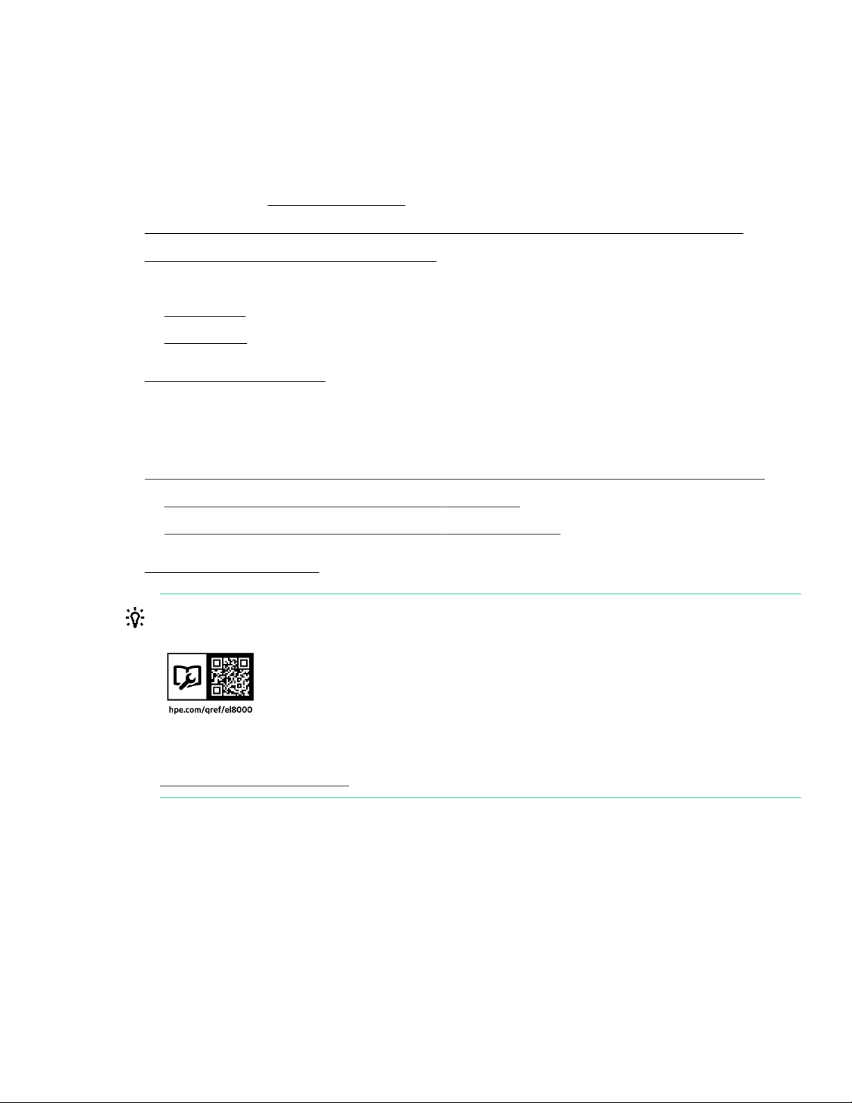
System components
Item Description
1 Fan assembly
2 Midplane assembly
3 HPE Edgeline EL8000 Converged Edge chassis
4 HPE ProLiant
5 HPE ProLiant e9102U server blade
6 Chassis Manager
7 Power supplies
HPE Edgeline EL8000 Converged Edge system
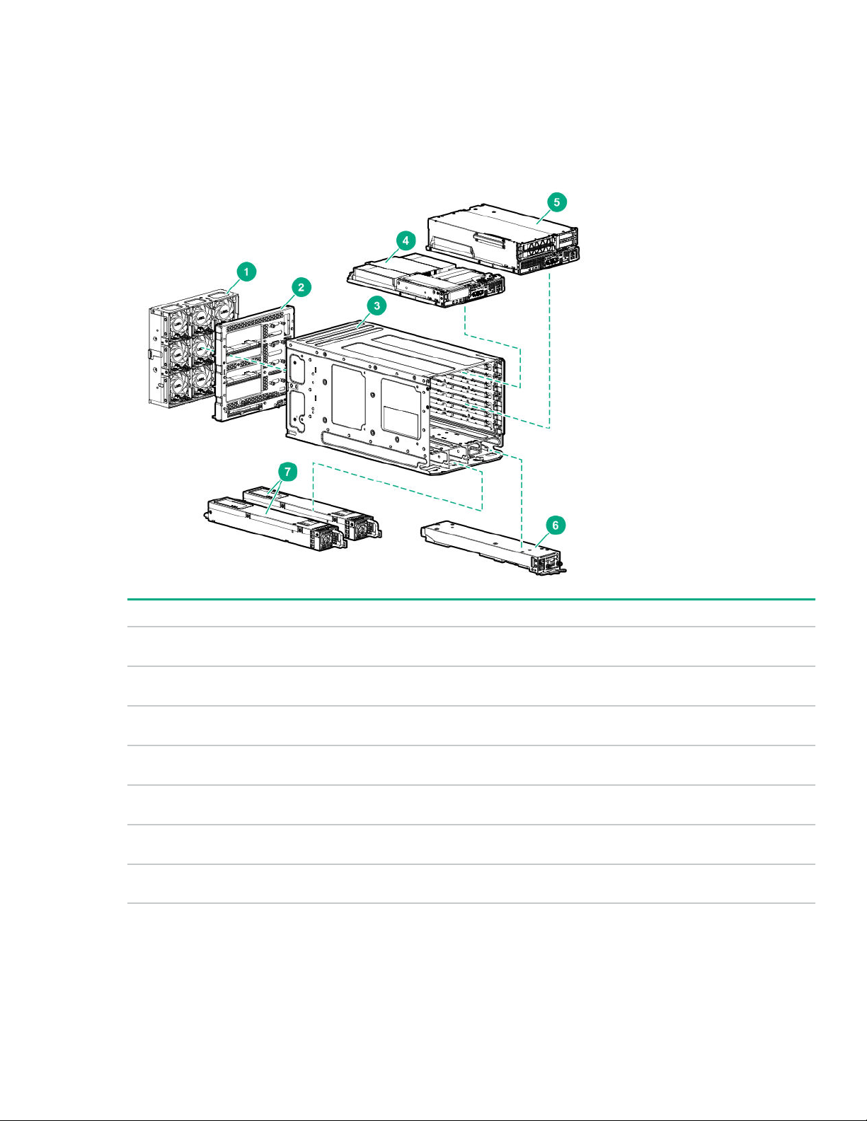
EL8000 chassis with 1U server blades installed
The EL8000 system can accommodate up to four 1U HPE ProLiant e910 server blades.
e9101U server blade
Component identification 9
Page 10
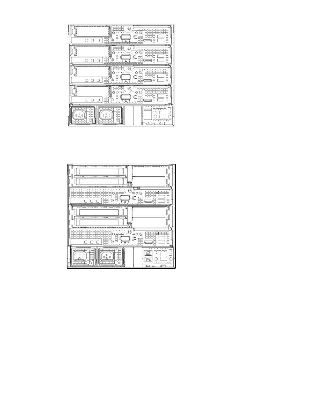
EL8000 chassis with 2U server blades installed
The EL8000 chassis can accommodate up to two 2U HPE ProLiant e910 server blades.
EL8000 Chassis with both 1U and 2U server blades installed
The EL8000 chassis with one 2U and two 1U server blades installed.
10 Component identification
Page 11
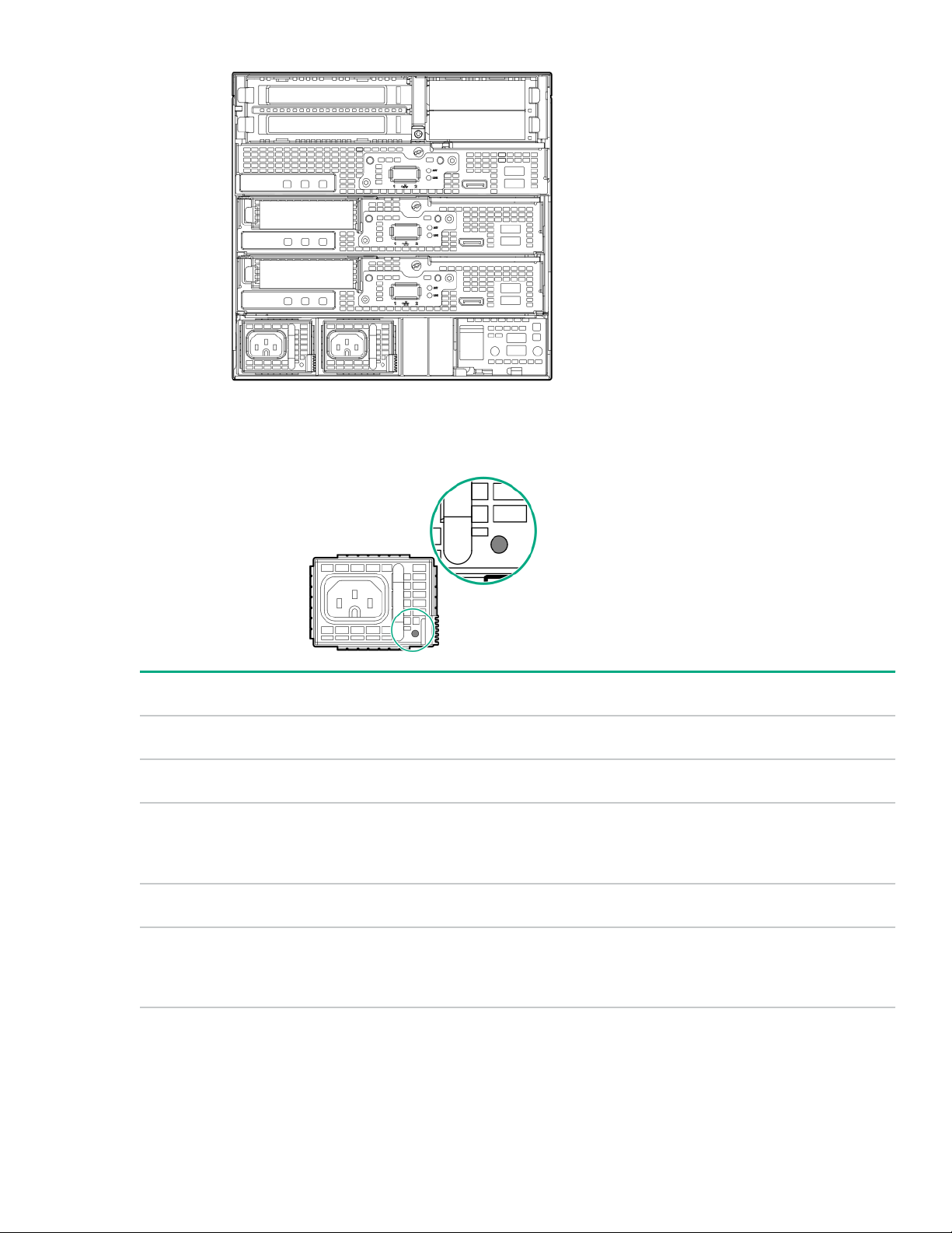
Power supply LEDs
AC power supply LED
Status Description
Solid Green System On and normal operation
Flashing Green Standby power present (power supply o)
Solid Amber Power supply failed (overvoltage/undervoltage,
overtemperature, overcurrent, short-circuit), fan failed, or
input overvoltage protection
Flashing Amber Power supply error
O No power present or standby power failed (overvoltage/
undervoltage, overtemperature, overcurrent, short-circuit, fan
lock)
Component identification 11
Page 12
DC power supply LED
Status Description
Solid Green System On and normal operation
Flashing Green Standby power present (power supply o)
Solid Amber Power supply failed (overvoltage/undervoltage,
overtemperature, overcurrent, short-circuit), fan failed, or
input overvoltage protection
Flashing Amber Power supply error
O No power present or standby power failed (overvoltage/
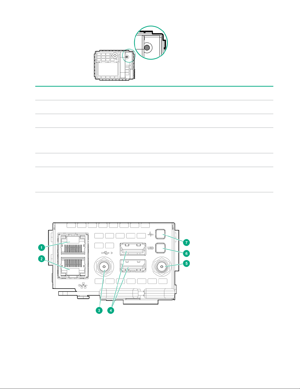
Chassis manager components
undervoltage, overtemperature, overcurrent, short-circuit, fan
lock)
12 Component identification
Page 13

Item Description
1 Management Network port
2 Blade maintenance network port
3 Antenna 1
4 Chassis manager USB ports
5 Antenna 2
6 Chassis UID Button/LED
7 Chassis Health LED
Component identification 13
Page 14
Rack mount option
There are two rack options available for installing the EL8000 chassis:
• Two-post rack mount option
• Four-post rack mount option
Installing the two-post rack mount kit
The two-post rack is available in 19 in and 23 in depth.
Prerequisites
Before you perform this procedure, make sure that you have the following items available:
• T-10 Torx screwdriver
• T-25 Torx screwdriver
Procedure
1. Install the brackets on rack columns.
When installing the rail kit on 19 in rack columns, remove the outer brackets and install only the inner brackets.
2. Loosen the screws on each bracket, to enable them to move freely.
14 Rack mount option
Page 15
3. Install the rack tray into the brackets:
a. Install the tray into the brackets.
b. Install two screws in the front and rear brackets each, and then tighten them.
Rack mount option 15
Page 16
c. Tighten the eight screws that were loosened in step 2.
4. Install the chassis on the rack tray:
a. Place the chassis on the rack tray.
b. Secure the chassis with two screws on the front.
16 Rack mount option
Page 17

c. Secure the chassis with two screws on the rear.
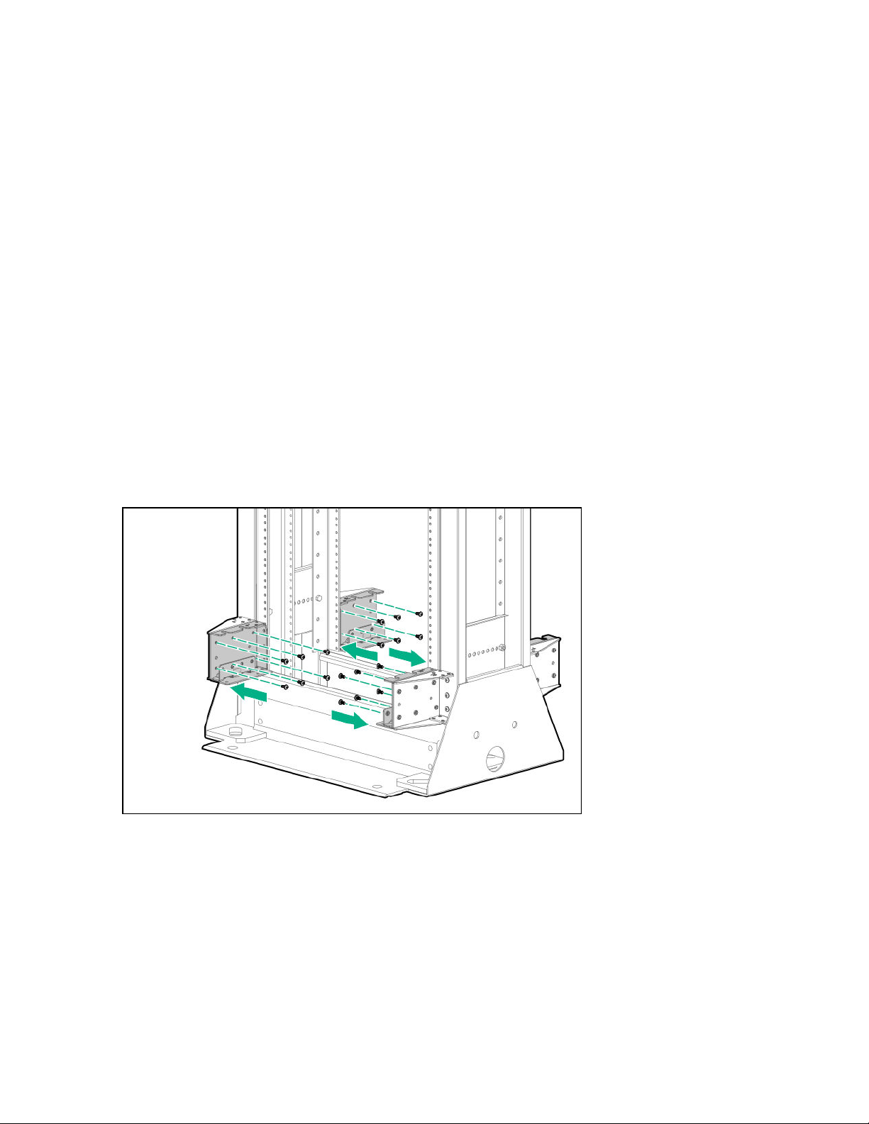
Installing the four-post rack mount kit
Two mounting locations are available for the four-post rack mounting:
•
Forward chassis rack mount- This mounting position is preferred when the cables connected to the chassis are at the rear
of the rack.
• Rear chassis rack mount- This mounting position is preferred when the cables connected to the chassis are at the front of
the rack. For this mounting option, the chassis is recessed in the rack.
Prerequisites
Before you perform this procedure, make sure that you have the following items available:
Rack mount option 17
Page 18

• T-10 Torx screwdriver
• T-25 Torx screwdriver
Procedure
1. Identify the mounting location, install the tray bracket, and stop the screw in correct location.
• Forward chassis rack mount
• Rear chassis rack mount
2. Install the rails into the rack.
18 Rack mount option
Page 19

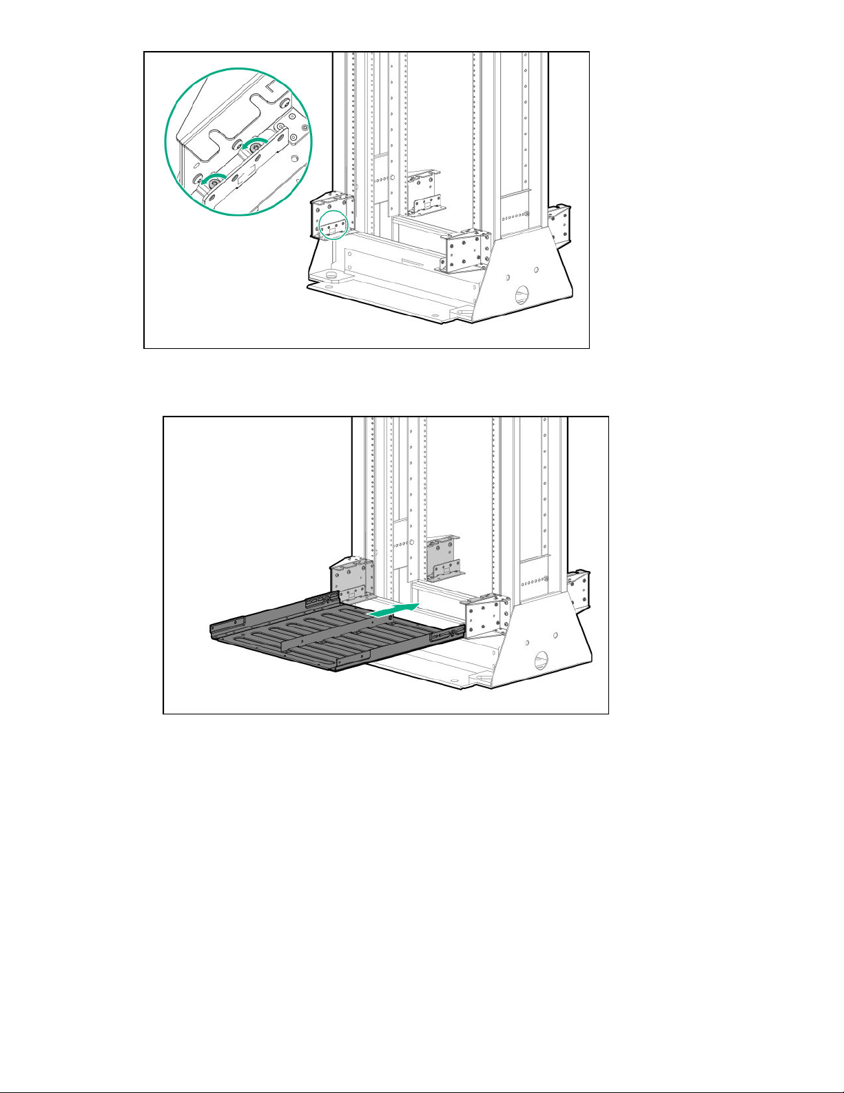
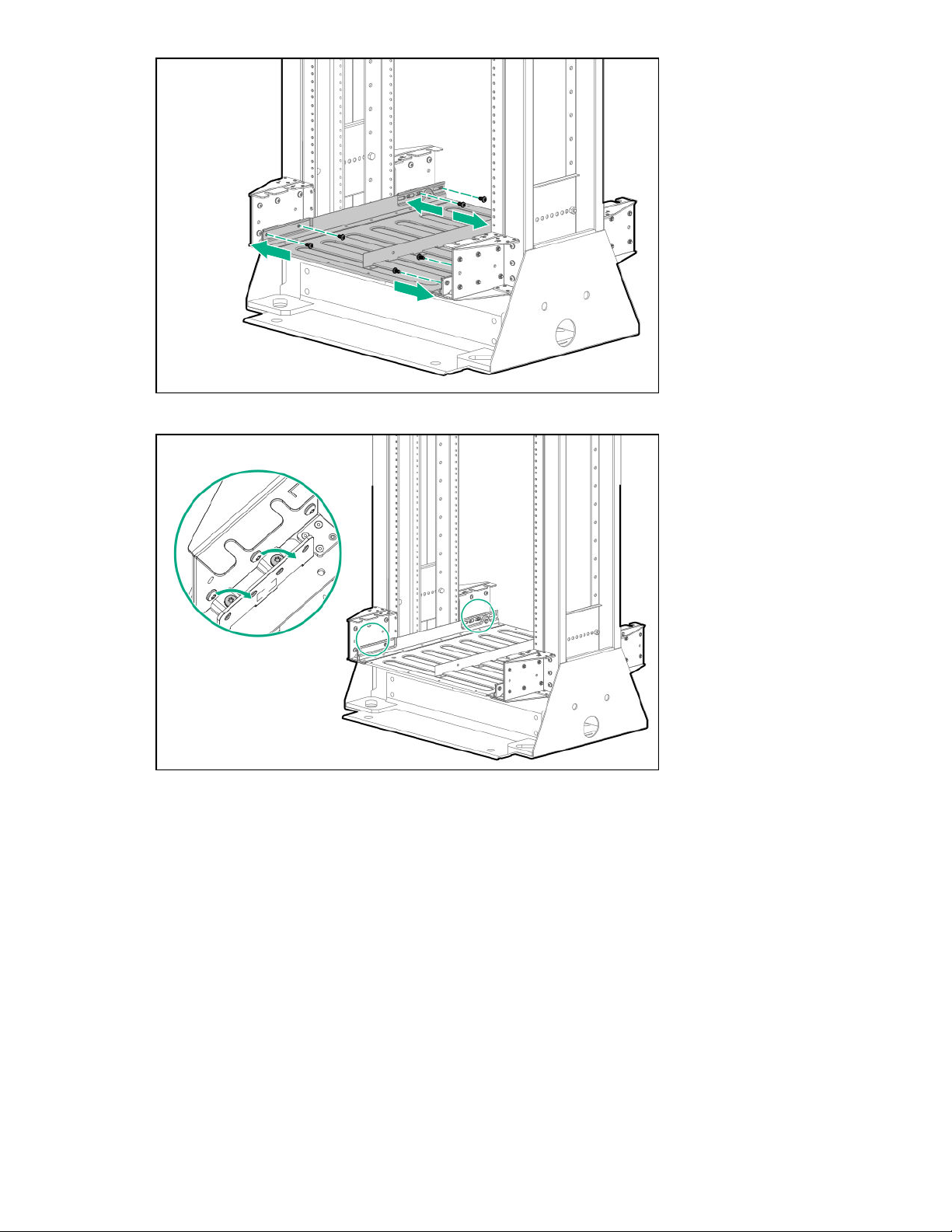
3. Install the rack tray on the rails, and then secure it.
Make sure that the tray slides under the bracket.
4. Place the chassis on the tray, and then secure it.
Rack mount option 19
Page 20

20 Rack mount option
Page 21

Associated hardware procedures
This chapter describes the hardware operations carried out before and after installing or removing a hardware option, or
performing system maintenance or troubleshooting.
Powering down the system
Before powering down the system for any upgrade or maintenance procedures, back up critical system data and programs.
Before performing chassis maintenance, shut down all blades installed in the chassis.
To power down, use one of the following methods:
• Press and hold the Power on button on the server blade.
This method initiates a controlled shutdown of applications and the OS before the server enters standby mode.
• Press and hold the Power On/Standby button of the blades installed in the chassis for more than 4 seconds to force the
system to power down.
This method forces the system to power down without properly exiting applications and the OS. If an application stops
responding, you can use this method to force a shutdown.
• Use the virtual power button in the Edgeline EL8000 Chassis Manager web interface.
• Use the virtual power button in the iLO web interface hosted on the blade.
• Enter the set power off b<slot#> at the chassis manager CLI. See the HPE Edgeline EL8000 Converged Edge
System Chassis Manager CLI User Guide on the HPE website for details on CLI commands.
Before proceeding, verify that the server blade is in standby mode by observing that the system power LED is amber. See
Power supply LEDs.
Powering up the system
If the HPE Edgeline EL8000 Converged Edge chassis is connected to a power source, it powers up automatically by default.
Generally, it has to be powered up only after a manual shutdown.
Use one of the following methods to power on blades:
•
Press and release the power button on the server blade.
• Use the virtual power button in theEdgeline EL8000 Chassis Manager web interface.
• Use the virtual power button in the iLO web interface hosted on the blade.
• Enter the set power on b<slot#> at the chassis manager CLI. See the HPE Edgeline EL8000 Converged Edge
System Chassis Manager CLI User Guide on the
Before proceeding, verify that the server blade is powered on by observing that the system power LED is green. See Power
supply LEDs.
HPE website for details on CLI commands.
Removing the blade from the chassis
Prerequisites
Before performing this procedure, make sure that you have the T-15 Torx key available.
Associated hardware procedures 21
Page 22

Procedure
1. Power down the system.
2. If locked, unlock the server blade.
3. Press and open the blade latch.
4. Remove the server blade.
Installing the server blade into the chassis
The HPE Edgeline EL8000 Converged Edge chassis supports HPE ProLiant e910 Server Blade. Permissible server blades
configurations:
•
Up to four 1U server blades
• Up to two 2U server blades
• Up to one 2U and two 1U server blades
22 Associated hardware procedures
Page 23

IMPORTANT: The 2U server blades must be installed in bay 1 and bay 5.
Prerequisites
Before performing this procedure, make sure that you have the T-15 Torx key available.
Procedure
1. Align the blade and install it in the chassis:
a. Insert the blade in the chassis.
b. Close the latch on the server blade and secure it.
2. Optional: Lock the server blade.
Associated hardware procedures 23
Page 24

Configuration
Prepare for configuration
Prepare to configure your new system by completing the tasks below.
1. Verify network connectivity
Ensure that the network connection is active.
2. Plan for the network address
If you do not have DHCP enabled on the network, you must have networking details ready: An IP address to assign, subnet
mask, gateway address, and DNS name. For initial setup, it is faster to allow automatic assignment of these details by
connecting your system to a DHCP enabled network.
Connecting to Edgeline EL8000 Chassis Manager the first time
Once the system is unboxed, connected to your management network, and powered up, there are a few options for accessing
Edgeline EL8000 Chassis Manager the first time. You can initially configure Edgeline EL8000 Chassis Manager by connecting
to:
• The Edgeline EL8000 Chassis Manager web interface through the management network.
• The Edgeline EL8000 Chassis Manager CLI using a DB9 null modem serial cable and retrieving the DHCP assigned IP
address or hostname. Note that since there is no serial port available on the Edgeline EL8000 Chassis Manager, you may
need to also use a USB-to-RS232 adapter.
Connecting to the web interface using Ethernet
You can acquire the IP address or hostname through your management network.
Prerequisites
• System hardware unboxed, installed, and powered up
• Username and password noted from the chassis tag
• Ethernet cable
• DHCP enabled network
Procedure
1. Connect an Ethernet cable between the MGMT port on the system chassis and your management network.
2. Wait for the hostname of your new system to propagate onto your network through DDNS and have an IP address
assigned through DHCP.
3. On a separate computer connected to your network, enter the address https://<Chassis Manager hostname
or IP address> in a browser window. HTTPS (HTTP exchanged over an SSL encrypted session) is required for
accessing the Edgeline EL8000 Chassis Manager web interface.
To use the hostname, enter the fully qualified domain name (if your computer is outside the domain) or just the hostname
(if your computer is inside the domain).
4. Log in with the default credentials listed on the system chassis tag.
24 Configuration
Page 25

Connecting to the CLI in a serial session
If ICMP ping or other tools are disabled on your management network, retrieve the IP address in a serial session.
Prerequisites
• System hardware unboxed, installed, and powered up
• Username and password noted from the chassis tag
• Null modem serial cable with connectors or adapters suitable for your environment
NOTE: The null modem serial cable must be connected to a USB port on the chassis.
• DHCP enabled management network
Procedure
1. Connect a USB-to-RS232 (serial) adapter to the USB port of the system.
2. Connect a null modem serial cable to the serial port of the adapter. Connect the other end to the system you are using to
configure. Note that you may need a second USB-to-RS232 adapter if the system you are using to configure has no serial
port.
3. Use a standard tool like PuTTY to start a serial terminal session on the system you are using to configure. Use the following
settings:
Specification Value
Serial Line Appropriate for the system you are using to connect
Baud rate 115200
Data bits 8
Parity None
Stop bit 1
Flow control XON/XOFF
4. Log in by entering the default credentials shown on the chassis tag at the prompt.
5. To see the network details, enter the show network command.
Edgeline EL8000 Chassis Manager web interface
Use the Edgeline EL8000 Chassis Manager web interface to manage your Edgeline EL8000. You can also use the Edgeline
EL8000 Chassis Manager CLI.
Browser requirements
The Edgeline EL8000 Chassis Manager web interface requires a browser that meets the following requirements:
• JavaScript—The Edgeline EL8000 Chassis Manager web interface uses client-side JavaScript extensively.
This setting is not enabled by default in all versions of Internet Explorer. To check or change this setting, see Enabling
JavaScript for Internet Explorer on page 26.
• Cookies—Cookies must be enabled for certain features to function correctly.
Configuration 25
Page 26

• Pop-up windows—Pop-up windows must be enabled for certain features to function correctly. Verify that pop-up blockers
are disabled.
• TLS—To access the Edgeline EL8000 Chassis Manager web interface, you must enable TLS 10 or later in your browser.
Supported browsers
Edgeline EL8000 Chassis Manager supports the latest versions of the following browsers:
• Microsoft Edge
• Mozilla Firefox
• Google Chrome mobile and desktop
• Microsoft Internet Explorer 11
Enabling JavaScript for Internet Explorer
Some versions of Internet Explorer have JavaScript disabled by default. Use the following procedure to enable JavaScript.
Procedure
1. Start Internet Explorer.
2. Select Tools > Internet options.
3. Click Security.
4. Click Custom level.
5. In the Scripting section, set Active scripting to Enable.
6. Click OK.
7. Refresh your browser window.
Logging in to the web interface
Procedure
1. Enter https://<EL8000CM host name or IP address>
When you access the Edgeline EL8000 Chassis Manager web interface, you must use HTTPS (HTTP exchanged over an
SSL encrypted session).
The Edgeline EL8000 Chassis Manager login page opens. If a login security banner is configured, the banner text is
displayed above the login section.
2. Enter a local account Username and Password, and then click Log In.
TIP: When logging in to the Edgeline EL8000 Chassis Manager web interface for the first time:
26 Configuration
•
The default username is Administrator. The username is case sensitive.
• The default password is printed on the label attached to the chassis.
Page 27

About the Edgeline EL8000 Chassis Manager web interface controls
The left pane of the Edgeline EL8000 Chassis Manager web interface can be hidden from view at any time. Hiding the left
pane gives more space for the main pages to be displayed, but hides the navigation tree.
• To hide the left pane, click X or click .
To show the left pane, click
•
Logout, lock, and help
There are three icons shown at the bottom of the left pane when the pane is open:
•
• —This icon locks Edgeline EL8000 Chassis Manager and prevents configuration changes in the web interface and
• —This icon displays the online help for the Edgeline EL8000 Chassis Manager web interface.
Confirmation, status, and error messages
Some pages of the Edgeline EL8000 Chassis Manager web interface require you to scroll down to see all the options available,
or to reach an Apply button. Confirmation, status and error messages display at the top of the page, so remember to scroll
back up to the top of the page after clicking Apply.
—This icon shows the currently logged-in username and a Logout option. Clicking Logout closes your web interface
session and returns to the login screen.
CLI. Clicking the icon opens a confirmation dialog. Click Lock System or No, Go Back. You are asked to verify your choice a
second time.
.
Complete the network configuration using Edgeline EL8000 Chassis Manager
Complete the configuration by performing the following tasks.
The details for these tasks can be found in the HPE Edgeline EL8000 Converged Edge System Chassis Manager User Guide at
http://www.hpe.com/support/EL8000-CM-UserGuide-en.
1. Configure all Edgeline EL8000 Chassis Manager network connection settings that you intend to use on the Network
pages:
• Configure the Domain Name on the General page.
• Choose and configure LAN addressing on the IPv4 or IPv6 pages.
Click here for detailed instructions about configuring network settings.
2. Update firmware or add files to the repository on the Firmware pages. Download firmware updates from the HPE Support
Center at http://www.hpe.com/support/hpesc.
Click here for detailed instructions about updating the firmware.
3. Register the product.
Network connection management
Edgeline EL8000 Chassis Manager provides multiple options for network connection.
Configuration 27
Page 28

To access the network settings, view or edit the network settings on the following pages:
• Summary
• General
• IPv4
• IPv6
Viewing the network configuration summary
Procedure
Click Network in the navigation tree.
The Summary tab is displayed.
Network configuration summary details
• Name—The name of the active Edgeline EL8000 Chassis Manager network interface.
• Host Name—The name assigned to the Edgeline EL8000 Chassis Manager subsystem. By default, the host name is
EL8000CM, followed by the system serial number. This value is used for the network name and must be unique.
NOTE: You can configure the Edgeline EL8000 Chassis Manager host name on the General tab.
• MAC Address—The MAC address of the Edgeline EL8000 Chassis Manager network interface.
• Permanent MAC Address—The unchangeable MAC address of the Edgeline EL8000 Chassis Manager network interface.
• FQDN—The fully qualified domain name of the system.
• IPv6 Default Gateway—When IPv6 is enabled, the gateway is the default IP address Edgeline EL8000 Chassis Manager
uses to access the network. When not enabled, this entry is blank.
• Speed (Mbps)—The speed of the wired network, measured in megabits per second.
IPv4 Summary details
• Address—The IP
• Address Origin—Indicates whether the address was supplied automatically by DHCP or is static.
• Gateway—The gateway address in use for the IPv4 protocol. If the value is 0.0.0.0, the gateway is not configured.
• Subnet Mask—The subnet mask of the IPv4 address currently in use. If the value is 0.0.0.0, no address is configured.
IPv6 Summary details
v4 address currently in use. If the value is 0.0.0.0, the IPv4 address is not configured.
• Address—The IP
• Address State—Indicates whether the address was supplied automatically or is static.
• Gateway—The gateway address in use for the IPv6 protocol. If the value is blank, the gateway is not configured.
• Prefix Length—The subnet mask of the IPv6 address currently in use.
28 Configuration
v6 address currently in use. If the value is blank, the IPv6 address is not configured.
Page 29

• Link Local Address—The IPv6 address for the network segment.
• Link Local Gateway—The IPv6 address of the local network segment gateway. If the value is blank, the gateway is not
configured.
• Prefix Length—The subnet mask of the IPv6 link-local address.
IPv6 Address Policy table
This table shows whether IPv6 or IPv4 addresses are preferred.
Configuring Host Name Settings
Use the General page to configure the Host Name and Domain Name. The host name and the domain name together
constitute the fully qualified domain name.
Prerequisites
Edgeline EL8000 Chassis Manager Admin privilege
Procedure
1. Click Network in the navigation tree, and then click the General tab.
2. Enter the Subsystem Name (Host name).
The host name is the DNS name of the Edgeline EL8000 Chassis Manager subsystem. This name can be used only if DHCP
and DNS are configured to connect to the Edgeline EL8000 Chassis Manager subsystem name instead of the IP address.
3. Enter the Domain Name if DHCP is not configured.
4. Click Apply.
Host name and domain name limitations
The Subsystem Name (Host name) is initially set at the factory, and is listed on the chassis tag. This default host name is a
combination of EL8000CM followed by the system serial number.
When reconfiguring the Host Name Settings, note the following:
• Name service limitations—The subsystem name is used as part of the DNS name.
◦ DNS allows alphanumeric characters and hyphens.
◦ Always start the hostname with a letter, and not with a number or a hyphen. Any combination of letters, numbers, and
the hyphen can be used after the first letter.
◦ Name service limitations also apply to the Domain Name.
• Namespace issues—To avoid these issues:
◦ Do not use the underscore character.
◦ Limit subsystem names to 15 characters.
◦ Verify that you can ping the Edgeline EL8000 Chassis Manager processor by IP address and by DNS name.
◦ Verify that NSLOOKUP resolves the Edgeline EL8000 Chassis Manager network address correctly and that no
namespace conflicts exist.
◦ Flush the DNS name if you make any namespace changes.
Configuration 29
Page 30

Configuring IPv4 settings
Prerequisites
Edgeline EL8000 Chassis Manager Admin privilege
Procedure
1. Click Network in the navigation tree, and then click the IPV4 tab.
2. Configure the DHCPv4 Configuration setting.
3. Configure the IPv4 Address Configuration settings.
4. Configure the DNS Configuration settings.
5. To save the changes you made on the IPv4 Settings page, click Apply.
6. When you are finished configuring the Edgeline EL8000 Chassis Manager network settings on the Network tabs, restart
the Edgeline EL8000 Chassis Manager system.
It might take several minutes before you can re-establish a connection.
DHCPv4 Configuration setting
The DHCPv4 setting is enabled by default.
Enable DHCPv4
Enables Edgeline EL8000 Chassis Manager to obtain an IP address (and other network specific address settings) from a
DHCP server.
NOTE: When DHCPv4 is enabled, the IPv4 Address Configuration section and DNS Configuration section are
automatically assigned. When the system is rebooted, these automatic assignments might change.
Static IPv4 Address Configuration settings
IPv4 Address
The Edgeline EL8000 Chassis Manager IP address. The IP address is supplied automatically when DHCP is enabled. When
DHCP is not enabled, enter a static IP address.
IPv4 Subnet Mask
The subnet mask of the IP network. The subnet mask is supplied automatically when DHCP is enabled. When DHCP is not
enabled, enter a subnet mask for the network.
IPv4 Gateway
The Edgeline EL8000 Chassis Manager gateway IP address. The Edgeline EL8000 Chassis Manager gateway IP address is
supplied automatically when DHCP is enabled. When DHCP is not enabled, enter an IP address for the gateway.
IPv4 DNS Configuration settings
Primary DNS Server
This value is supplied automatically when DHCP is enabled. If you are using a static IP address, no name servers are used.
Secondary DNS Server
This value is supplied automatically when DHCP is enabled. If you are using a static IP address, no name servers are used.
30 Configuration
Page 31

Tertiary DNS Server
This value is supplied automatically when DHCP is enabled. If you are using a static IP address, no name servers are used.
Configuring IPv6 settings
Prerequisites
Edgeline EL8000 Chassis Manager Admin privilege
Procedure
1. Click Network in the navigation tree.
2. Click the IPv6 tab.
3. Configure the Global IPv6 Configuration setting.
4. Configure the IPv6 Configuration settings.
5. Configure the DNS Configuration settings.
6. To save the changes you made on the IPv6 Settings page, click Apply.
7. If you are finished configuring the Edgeline EL8000 Chassis Manager network settings, restart Edgeline EL8000 Chassis
Manager.
It might take several minutes before you can re-establish a connection.
IPv6 Configuration settings
Global IPv6 Configuration
Client Applications use IPv6 first
This option specifies which protocol Edgeline EL8000 Chassis Manager is tried first when accessing a client application. It
is useful when both IP
applications. This setting also applies to lists of addresses received from the name resolver when using FQDNs to
configure NTP.
• Enable this option if you want Edgeline EL8000 Chassis Manager to use IPv6 first.
• Disable this option if you want Edgeline EL8000 Chassis Manager to use IPv4 first.
If communication fails when attempting to use the first protocol, Edgeline EL8000 Chassis Manager automatically tries the
second protocol.
This option is enabled by default.
IPv6 Configuration
Enable IPv6 in Auto Mode
Enable this option to configure Edgeline EL8000 Chassis Manager to use an IP
server is available, IPv6 automatically falls back to using SLAAC. This option is enabled by default.
Edgeline EL8000 Chassis Manager creates its own link-local address even when this option is not enabled.
v4 and IPv6 service addresses are configured for Edgeline EL8000 Chassis Manager client
v6 DHCP server (if found). If no IPv6 DHCP
IPv6 Static Address
When assigning static IPv6 addresses, enter the main IP address here.
Configuration 31
Page 32

IPv6 Static Address Prefix Length
When assigning static IPv6 addresses, enter the prefix length here.
IPv6 Default Gateway
When assigning static IPv6 addresses, enter the default IPv6 gateway here.
DNS Configuration
When assigning static IPv6 addresses, enter the Primary, Secondary, and Tertiary DNS Server addresses.
Viewing installed firmware information
Procedure
Click Firmware in the navigation tree.
The Firmware page displays firmware information for various components.
Firmware types
The firmware types listed on the Firmware page vary based on the system configuration.
For most configurations, the CPLD, Edgeline EL8000 Chassis Manager firmware, and base image are listed.
Firmware details
The Firmware page displays the following information for each listed firmware type:
• Firmware name—The category name of the firmware.
• Firmware version—The currently installed version number of the firmware.
Updating firmware
While firmware can be updated using components uploaded to the Edgeline EL8000 Chassis Manager Repository, you can also
update firmware directly.
Prerequisites
Edgeline EL8000 Chassis Manager Admin privilege
Procedure
1. Click Firmware in the navigation tree, and then click Update Firmware in the right pane.
2. Select the Local file or Remote file option.
3. Depending on the option you selected, do one of the following:
a. In the File box, click Browse (Internet Explorer, Edge, or Firefox) or Choose File (Chrome), and then specify the location
of the firmware component.
b. In the URL box, enter the URL for a firmware component on an accessible web server.
4. Click Flash.
The firmware update status will be visible in the event log.
32 Configuration
Page 33

Adding components to the Edgeline EL8000 Chassis Manager Repository
Prerequisites
Edgeline EL8000 Chassis Manager Admin privilege
Procedure
1. Click Firmware in the navigation tree, and then click Upload to Repository in the right pane.
2. Select the Local file or Remote file option.
3. Depending on the option you selected, do one of the following:
a. In the File box, click Browse (Internet Explorer, Edge, or Firefox) or Choose File (Chrome), and then specify the location
of the firmware component.
b. In the URL box, enter the URL for a firmware component on an accessible web server.
4. Click Upload.
The file is uploaded to the repository and displayed in the repository contents list.
IMPORTANT: Do not exceed the repository storage capacity. Exceeding the storage capacity will force all open
sessions to the Edgeline EL8000 Chassis Manager to log out. If this happens, log in again and delete stored files until
the repository storage is below the maximum capacity.
Installing a component from the Edgeline EL8000 Chassis Manager Repository
You can install new firmware from the Edgeline EL8000 Chassis Manager Repository page.
Prerequisites
Edgeline EL8000 Chassis Manager Admin privilege
Procedure
1. Click Firmware in the navigation tree, and then click Repository.
2. Click the install component icon next to the component you want to install.
3. Click Yes, install now.
The update begins immediately.
Managing chassis power and resetting Edgeline EL8000 Chassis Manager
Prerequisites
Edgeline EL8000 Chassis Manager Admin privilege
Procedure
1. Click Power and Thermal in the navigation tree, and then click the Management Power tab.
2. To reset the chassis manager power supply, click Auxiliary Reset, and then click Yes, Reset Now.
Configuration 33
Page 34

Resetting the chassis manager power supply resets all chassis manager components, including the Ethernet switch
connection to the blade iLO processors. An auxiliary reset causes a short disruption to the internal management and
production networks, but does not aect blade power.
3. To reset the Edgeline EL8000 Chassis Manager, click Reset EL8000CM, and then click Yes, Reset Now.
Using the Reset option does not make any configuration changes, but ends all active connections to the firmware. If a
firmware file upload is in progress, it is terminated. If a firmware flash is in progress, you cannot reset until the process is
finished. Wait a few minutes before attempting to log in to a new session.
Prepare the system for daily use
Prepare your new system for service by completing the following tasks.
The details for these tasks can be found in the HPE Edgeline EL8000 Converged Edge System Chassis Manager User Guide at
http://www.hpe.com/support/EL8000-CM-UserGuide-en.
• Access Edgeline EL8000 Chassis Manager from practically anywhere, or use a link on the Blades page to access the host
operating system using iLO Remote Console (after acquiring an iLO Advanced license).
• Add authorized user accounts in Edgeline EL8000 Chassis Manager on the User Administration page.
NOTE: The default Administrator account cannot be deleted.
• Add SSH keys for each user on the Security page.
• Replace the default self-signed certificate and create a trusted SSL certificate for Edgeline EL8000 Chassis Manager on the
SSL Certificate page.
• Control the system and chassis power, and view temperatures, from the Power and Thermal pages.
• Back up the Edgeline EL8000 Chassis Manager configuration on the Backup & Restore page.
• Troubleshoot system issues by viewing the Health and Event logs on the Logs page.
Registering the product
To experience quicker service and more eicient support, register the product at the Hewlett Packard Enterprise Product
Registration website.
34 Configuration
Page 35

Troubleshooting
Troubleshooting preparation
Prerequisites for troubleshooting
Complete the following steps before preparing the system for diagnosis.
Prerequisites
WARNING: To avoid potential issues, ALWAYS read the warnings and cautionary information in the product
documentation before removing, replacing, reseating, or modifying system components.
Procedure
1. Review the important safety information.
2. Gather symptom information.
3. If it is necessary to contact Hewlett Packard Enterprise, submit a support case through Active Health System Viewer.
For more information, see the Active Health System Viewer user guide on the Hewlett Packard Enterprise website (http://
www.hpe.com/support/ahsv-docs).
Important safety information
Familiarize yourself with the safety information in the following sections before troubleshooting the system.
Important safety information
Before servicing this product, read Safety and Compliance Information for Server, Storage, Power, Networking, and Rack
Products on the Hewlett Packard Enterprise website.
Symbols on equipment
The following symbols might be found on the equipment to indicate the presence of potentially hazardous conditions.
This symbol indicates the presence of hazardous energy circuits or electric shock hazards. Refer all
servicing to qualified personnel.
WARNING: To reduce the risk of injury from electric shock hazards, do not open this enclosure. Refer
all maintenance, upgrades, and servicing to qualified personnel.
This symbol indicates the presence of electric shock hazards. The area contains no user or field
serviceable parts. Do not open for any reason.
WARNING: To reduce the risk of injury from electric shock hazards, do not open this enclosure.
Troubleshooting 35
Page 36

This symbol on an RJ-45 receptacle indicates a network interface connection.
WARNING: To reduce the risk of electric shock, fire, or damage to the equipment, do not plug telephone
or telecommunications connectors into this receptacle.
This symbol indicates the presence of a hot surface or hot component. If this surface is contacted, the
potential for injury exists.
WARNING: To reduce the risk of injury from a hot component, allow the surface to cool before touching.
This symbol indicates that the component exceeds the recommended weight for one individual to
handle safely.
WARNING: To reduce the risk of personal injury or damage to the equipment, observe local
occupational health and safety requirements and guidelines for manual material handling.
These symbols, on power supplies or systems, indicate that the equipment is supplied by multiple
sources of power.
WARNING: To reduce the risk of injury from electric shock, remove all power cords to disconnect power
from the system completely.
Warnings and cautions
WARNING: Only authorized technicians trained by Hewlett Packard Enterprise should attempt to repair this equipment.
All troubleshooting and repair procedures are detailed to allow only subassembly/module-level repair. Because of the
complexity of the individual boards and subassemblies, no one should attempt to make repairs at the component level
or to make modifications to any printed wiring board. Improper repairs can create a safety hazard.
WARNING: To reduce the risk of personal injury or damage to the equipment, consult the safety information and user
documentation provided with the server before attempting the installation.
Some servers contain high energy circuits, high current circuits, moving parts (such as fan blades), or any combination of
these hazards, that may be exposed if covers and access panels are removed while the product is connected to a power
source. These products are intended to be serviced only by qualified personnel who have been trained to deal with
these hazards. Do not remove enclosures or attempt to bypass any interlocks designed to guard against these
hazardous conditions.
WARNING: To reduce the risk of personal injury or damage to the equipment, be sure that:
• The leveling feet are extended to the floor.
• The full weight of the rack rests on the leveling feet.
• The stabilizing feet are attached to the rack if it is a single-rack installation.
• The racks are coupled together in multiple-rack installations.
• Only one component is extended at a time. A rack may become unstable if more than one component is extended for
any reason.
36 Troubleshooting
Page 37

WARNING: To reduce the risk of electric shock or damage to the equipment:
• Do not disable the power cord grounding plug. The grounding plug is an important safety feature.
• Plug the power cord into a grounded (earthed) electrical outlet that is easily accessible at all times.
• Unplug the power cord from the power supply to disconnect power to the equipment.
• Do not route the power cord where it can be walked on or pinched by items placed against it. Pay particular
attention to the plug, electrical outlet, and the point where the cord extends from the system.
WARNING: To reduce the risk of personal injury or damage to the equipment:
• Observe local occupation health and safety requirements and guidelines for manual
handling.
• Obtain adequate assistance to lift and stabilize the chassis during installation or
removal.
• The server is unstable when not fastened to the rails.
• When mounting the server in a rack, remove the power supplies and any other
removable module to reduce the overall weight of the product
CAUTION: To properly ventilate the system, you must provide at least 76 cm (30 in) of clearance at the front and back
of the server.
CAUTION: The server is designed to be electrically grounded (earthed). To ensure proper operation, plug the AC power
cord into a properly grounded AC outlet only.
Electrostatic discharge
Preventing electrostatic discharge
To prevent damaging the system, be aware of the precautions you must follow when setting up the system or handling parts.
A discharge of static electricity from a finger or other conductor may damage system boards or other static-sensitive devices.
This type of damage may reduce the life expectancy of the device.
Procedure
•
Avoid hand contact by transporting and storing products in static-safe containers.
• Keep electrostatic-sensitive parts in their containers until they arrive at static-free workstations.
• Place parts on a grounded surface before removing them from their containers.
• Avoid touching pins, leads, or circuitry.
• Always be properly grounded when touching a static-sensitive component or assembly.
Grounding methods to prevent electrostatic discharge
Several methods are used for grounding. Use one or more of the following methods when handling or installing electrostaticsensitive parts:
Troubleshooting 37
Page 38

• Use a wrist strap connected by a ground cord to a grounded workstation or computer chassis. Wrist straps are flexible
straps with a minimum of 1 megohm ±10 percent resistance in the ground cords. To provide proper ground, wear the strap
snug against the skin.
• Use heel straps, toe straps, or boot straps at standing workstations. Wear the straps on both feet when standing on
conductive floors or dissipating floor mats.
• Use conductive field service tools.
• Use a portable field service kit with a folding static-dissipating work mat.
If you do not have any of the suggested equipment for proper grounding, have an authorized reseller install the part.
For more information on static electricity or assistance with product installation, contact an authorized reseller.
Collecting symptom information
Before troubleshooting a system issue, collect the symptom information. Download the Active Health System Log using the
Active Health System Viewer, if possible.
For more information, see the Active Health System Viewer user guide on the Hewlett Packard Enterprise website (http://
www.hpe.com/support/ahsv-docs).
Preparing the EL8000 system for diagnosis
Procedure
1. Verify that the system is in the proper operating environment with adequate power, air conditioning, and humidity control.
2. Record any error messages displayed by the system.
3. Collect all tools and utilities necessary to troubleshoot the issue, such as a Torx screwdriver, loopback adapters, an ESD
wrist strap, and software utilities.
For product-specific information, Hewlett Packard Enterprise recommends that you have access to the product
information.
4. Review the iLO Integrated Management Log (IML).
5. Record the data displayed in the iLO logs.
Hardware problems
General hardware problems
The CM configured with static IP address reverts to DHCP when moved to a new chassis
Symptom
The CM configured with static IP address reverts to DHCP when moved to a new chassis.
Cause
The network stack compares the MAC address which is used when the configuration was saved against the current MAC
address. If the current MAC address does not match, the configuration reverts to default. The MAC address of the CM is saved
in the chassis midplane. Moving the CM between chassis results in a mismatch between the address saved in the configuration
and the current address. Hence, the CM reverts to DHCP.
38 Troubleshooting
Page 39

Action
Reconfigure the chassis manager on the new chassis.
Power problems
HPE Edgeline 1500 CM module powers on without being fully inserted to the chassis
Symptom
The HPE Moonshot 1500 CM module powers on without being fully inserted to the chassis. If the CM is not fully inserted, it
may cause the fan to make load noise and the CM fails to communicate with the cartridges.
Action
Make sure that the CM is fully inserted. Open the latch fully then press the CM in fully, then close the latch.
Troubleshooting 39
Page 40

Warranty and regulatory information
Warranty information
To view the warranty information for your product, see the links provided below:
HPE ProLiant and IA-32 Servers and Options
www.hpe.com/support/ProLiantServers-Warranties
HPE Enterprise and Cloudline Servers
www.hpe.com/support/EnterpriseServers-Warranties
HPE Storage Products
www.hpe.com/support/Storage-Warranties
HPE Networking Products
www.hpe.com/support/Networking-Warranties
Regulatory information
To view the regulatory information for your product, view the Safety and Compliance Information for Server, Storage, Power,
Networking, and Rack Products, available at the Hewlett Packard Enterprise Support Center:
www.hpe.com/support/Safety-Compliance-EnterpriseProducts
Additional regulatory information
Hewlett Packard Enterprise is committed to providing our customers with information about the chemical substances in our
products as needed to comply with legal requirements such as REACH (Regulation EC No 1907/2006 of the European
Parliament and the Council). A chemical information report for this product can be found at:
www.hpe.com/info/reach
For Hewlett Packard Enterprise product environmental and safety information and compliance data, including RoHS and
REACH, see:
www.hpe.com/info/ecodata
For Hewlett Packard Enterprise environmental information, including company programs, product recycling, and energy
eiciency,
www.hpe.com/info/environment
see:
Notices for Eurasian Economic Union
Manufacturer and Local Representative Information
Manufacturer information:
Hewlett Packard Enterprise, 6280 America Center Drive, San Jose, CA 95002 U.S.
Local representative information Russian:
• Russia
ООО "Хью
шоссе, 16А, стр.3, Телефон: +7 499 403 4248 Факс: +7 499 403 4677
• Kazakhstan
40 Warranty and regulatory information
летт Паккард Энтерпрайз", Российская Федерация, 125171, г. Москва, Ленинградское
Page 41

TOO «Хьюлетт-Паккард (К)», Республика Казахстан, 050040, г. Алматы, Бостандыкский район,
проспект Аль-Фараби, 77/7, Телефон/факс: + 7 727 355 35 50
Local representative information Kazakh:
• Russia
ЖШС "Хьюлетт Паккард Энтерпрайз", Ресей Федерациясы, 125171, Мәскеу, Ленинград тас жолы,
16A блок 3, Телефон: +7 499 403 4248 Факс: +7 499 403 4677
• Kazakhstan
ЖШС «Хьюлетт-Паккард (К)», Қазақстан Республикасы, 050040, Алматы к., Бостандык ауданы, ӘлФараби даңғ ылы, 77/7, Телефон/факс: +7 727 355 35 50
Manufacturing date:
The manufacturing date is defined by the serial number.
If you need help identifying the manufacturing date, contact tre@hpe.com.
Turkey RoHS material content declaration
Türkiye Cumhuriyeti: AEEE Yönetmeliğine Uygundur
Ukraine RoHS material content declaration
Federal Communications Commission notice for Class A equipment
This device complies with part 15 of the FCC Rules. Operation is subject to the following conditions:
This device may not cause harmful interference.
•
• This device must accept any interference received, including interference that may cause undesired operation.
This equipment has been tested and found to comply with the limits for a Class A digital device, pursuant to part 15 of the FCC
Rules. These limits are designed to provide reasonable protection against harmful interference when the equipment is
operated in a commercial environment. This equipment generates, uses, and can radiate radio frequency energy and, if not
installed and used in accordance with the instruction manual, may cause harmful interference to radio communications.
Operation of this equipment in a residential area is likely to cause harmful interference in which case the user will be required
to correct the interference at their own expense.
Warranty and regulatory information 41
Page 42

WARNING:
1. This equipment complies with radio frequency (RF) exposure limits adopted by the Federal Communications
Commission for an uncontrolled environment. This equipment should be installed and operated with a minimum
distance of 20 cm between the radiator and your body.
2. Changes or modifications not expressly approved by the party responsible for compliance could void the authority of
the user to operate the equipment.
Canada, Industry Canada (IC) Notices
This device complies with Industry Canada license-exempt RSS standards. Operation is subject to the following conditions:
1. This device may not cause interference.
2. This device must accept any interference, including interference that may cause undesired operation of the device.
Under Industry Canada regulations, the radio transmitters in this device may only operate using an antenna of a type and
maximum (or lesser) gain approved for the transmitter by Industry Canada. To reduce potential radio interference to other
users, the antenna type and its gain should be so chosen that the equivalent isotropically radiated power (e.i.r.p.) is not more
than what is necessary for successful communication.
WARNING: The device for operation in the band 5150 MHz to 5250 MHz is only for indoor use to reduce the potential
for harmful interference to cochannel mobile satellite systems.
Radio Frequency (RF) Exposure Information
This equipment complies with radio frequency (RF) exposure limits adopted by the Federal Communications Commission for
an uncontrolled environment. This equipment should be installed and operated with a minimum distance of 20 cm between the
radiator and your body.
This radio transmitter (IC:24448-EL8000530S) has been approved by Industry Canada to operate with the antenna types
listed below with the maximum permissible gain indicated. Antenna types not included in this list, having a gain greater than
the maximum gain indicated for that type, are strictly prohibited for use with this device. For maximum antenna gain, refer to
the table:
Frequency (MHz) Gain (dBi) Antenna Type Antenna Connector
2400-2500 238
5150-5250 325
5250-5350 325
5470-5725 378
5725-5850 394
Canada, avis d'Industry Canada (IC)
Cet appareil est conforme aux normes d'exemption de licence RSS d'Industry Canada.
Son fonctionnement est soumis aux deux conditions suivantes:
Dipole R-SMA
1. Cet appareil ne doit pas causer d'interférence.
2. Cet appareil doit accepter toute interférence, notamment les interférences qui peuvent aecter son fonctionnement.
Conformément aux réglementations d'Industry Canada, les émetteurs radio de cet appareil ne peuvent fonctionner qu'à l'aide
d'une antenne dont le type et le gain maximal (ou minimal) pour ces émetteurs - transmetteurs sont approuvés par Industry
42 Warranty and regulatory information
Page 43

Canada. Pour réduire le risque d'interférence éventuelle pour les autres utilisateurs, le type et le gain de l'antenne doivent être
choisis de manière à ce que la puissance isotrope rayonnée é quivalente (p.i.r.e.) minimale nécessaire à une bonne
communication soit fournie.
WARNING: Les dispositifs fonctionnant dans la bande 5150 MHz - 5250 MHz sont réservés uniquement pour une
utilisation à l'intérieur afin de réduire les risques de brouillage préjudiciable aux systèmes de satellites mobiles utilisant
les mêmes canaux.
Informations sur l'exposition à la fréquence radio (FR)
Cet équipement est conforme aux limites d'exposition aux rayonnements IC établies pour un environnement non contrôlé. Cet
équipement doit être installé et utilisé avec un minimum de 20 cm de distance entre la source de rayonnement et votre corps.
Cet émetteur radio (IC: 24448-EL8000530S) a été approuvé par Industrie Canada pour fonctionner avec les types d'antennes
énumérés ci-dessous avec le gain maximal autorisé indiqué. Les types d'antenne non inclus dans cette liste, ayant un gain
supérieur au gain maximal indiqué pour ce type, sont strictement interdits d'utilisation avec cet appareil. Le gain d'antenne
maximal (voir le tableau ci-dessous
La fréquence (MHz)
2400-2500 238
5150-5250 325
5250-5350 325
5470-5725 378
5725-5850 394
Gain (dBi) Type d'antenne Connecteur d'antenne
Dipôle R-SMA
Brazil certification notice
WARNING: Este equipamento não tem direito à proteção contra interferência prejudicial e não pode causar interferência
em sistemas devidamente autorizados
Japanese certification notice
IMPORTANT: 52GHz 帯及び 53GHz 帯の利用は、 総務省に登録済の 52GHz 帯高出力基地局等と通信する
場合を除き、屋内に限定されています.
Korean certification notice for class A equipment
CAUTION: 이 기기는 업무용 환경에서 사용할 목적으로 적합성평가를 받은 기기로서 가정용 환경에서 사용
하는 경우 전파간섭의 우려가 있습니다.
WARNING: 해당 무선설비가 전파혼신 가능성이 있으므로 인명안전과 관련된 서비스는 할 수 없음”.
Warranty and regulatory information 43
Page 44

Specifications
Environmental specifications
Table 1: Standard specifications
Specification Value
Temperature range
1
Operating 0°C to 55°C (32°F to 131°F)
—
2
Nonoperating -30°C to 60°C (-22°F to 140°F)
Relative humidity (noncondensing)
—
Operating 8% to 90% at 28°C (824°F) maximum wet bulb temperature
Non-Operating 5% to 95% at 387°C (1017°F) maximum wet bulb
temperature
1
All temperature ratings shown are for sea level. An altitude derating of 10°C per 3048 m (18°F per 1000 ft) to 3048 m (10000 ft) is
applicable. No direct sunlight allowed. Maximum rate of change is 20°C per hour (36°F per hour). No restrictions on product configurations.
Not rated for operation over 3048 m (10000 ft).
2
Fan failure might reduce performance.
Table 2: ASHRAE Class A4 specifications
Specification Value
Temperature range
1
—
Operating 0°C to 45°C (32°F to 113°F)
Nonoperating -10°C to 60°C (-22°F to 140°F)
Relative humidity (noncondensing)
Operating 8% to 90% at 28°C (824°F) maximum wet bulb temperature
Non-Operating 5% to 95% at 387°C (1017°F) maximum wet bulb
1
All temperature ratings shown are for sea level. An altitude derating of 10°C per 125 m (18°F per 410 ft) to 900 m (2953 ft) is applicable.
No direct sunlight allowed. Maximum rate of change is 20°C per hour (36°F per hour). No restrictions on product configurations except for
rotating hard drives. PCI cards must be rated for continuous operation with 60°C cooling air. Not rated for operation over 3048 m (10000
ft).
2
Fan failure might reduce performance.
44 Specifications
10°C to 35°C (50°F to 95°F) when GPU is installed
—
temperature
2
Page 45

Table 3: Extended Edgeline specifications
Specification Value
Temperature range
Operating 0°C to 55°C (32°F to 131°F)
Nonoperating -30°C to 60°C (-22°F to 140°F)
Relative humidity (noncondensing)
Operating 8% to 90% at 28°C (824°F) maximum wet bulb temperature
Non-Operating 5% to 95% at 387°C (1017°F) maximum wet bulb
1
All temperature ratings shown are for sea level. An altitude derating of 10°C per 305 m (18°F per 1000 ft) to 3048 m (10000 ft) is
applicable. No direct sunlight allowed. Maximum rate of change is 20°C per hour (36°F per hour). No restrictions on product configurations
except for rotating hard drives. PCI cards must be rated for continuous operation with 60°C cooling air. Solid-state drives must be rated for
continuous operation with 65°C cooling air. Not rated for operation over 3030 m (10000 ft).
1
Mechanical specifications
Specification Value
—
—
temperature
Height 216 cm (85 in) for 5U
Depth 4318 cm (17 in)
Width 221 cm (87 in)
Weight
With two 2U e910 server blades installed 52 lbs
With one 2U and two 1U e910 server blades 55 lbs
With four 1U e910 server blades installed 58 lbs
Power supply specifications
Depending on installed options, the system is configured with one of the following power supplies:
• 1500W Hot Plug Power Supply
• 1500W -48VDC Hot Plug Power Supply
—
For detailed power supply specifications, see the QuickSpecs on the Hewlett Packard Enterprise website (http://
www.hpe.com/info/proliant/powersupply).
Specifications 45
Page 46

1500W Hot-plug Power Supply
Specification Value
Input requirements
Rated input voltage
Rated input frequency
Rated input current
Maximum rated input power
BTUs per hour
Power supply output
Rated steady-state power
—
90 VAC to 264 VAC
47Hz to 63 Hz
15 A at 100 VAC
69 A at 240 VAC
1394 W at 90 VAC
1636 W at 264 VAC
4757 at 90 VAC
5582 at 264 VAC
—
1500 W at 200 VAC to 240 VAC
1400 W at 110 VAC to 120 VAC
1260 W for 100 VAC
Maximum peak power
-48VDC Hot Plug Power Supply
Specification Value
Input requirements
Rated input voltage
Rated input current
Rated input power (W)
1500 W at 200 VAC to 240 VAC
1400 W at 110 VAC to 120 VAC
1260 W for 100 VAC
—
-40 VDC to -72 VDC
-48 VDC nominal input
38 A at -48 VDC
25 A at -72 VDC
1670 W at -48 to -60 VDC
Table Continued
46 Specifications
Page 47

Specification Value
Rated input power (BTUs per hour)
Power supply output
Rated steady-state power 1500 W at -48 VDC to -60 VDC
Maximum peak power 1500 W at -48 VDC to -60 VDC
WARNING: To reduce the risk of electric shock or energy hazards:
• This equipment must be installed by trained service personnel.
• Connect the equipment to a reliably grounded secondary circuit source. A secondary circuit has no direct connection
to a primary circuit and derives its power from a transformer, converter, or equivalent isolation device.
• The branch circuit overcurrent protection must be rated 27 A.
CAUTION: This equipment is designed to permit the connection of the earthed conductor of the DC supply circuit to the
earthing conductor at the equipment.
If this connection is made, all of the following must be met:
• This equipment must be connected directly to the DC supply system earthing electrode conductor or to a bonding
jumper from an earthing terminal bar or bus to which the DC supply system earthing electrode conductor is
connected.
6337 at -48 VDC
6094 at -72 VDC
—
• This equipment must be located in the same immediate area (such as adjacent cabinets) as any other equipment
that has a connection between the earthed conductor of the same DC supply circuit and the earthing conductor, and
also the point of earthing of the DC system. The DC system must be earthed elsewhere.
• The DC supply source is to be located within the same premises as the equipment.
• Switching or disconnecting devices must not be in the earthed circuit conductor between the DC source and the
point of connection of the earthing electrode conductor.
Specifications 47
Page 48

Websites
General websites
Hewlett Packard Enterprise Information Library
www.hpe.com/info/EIL
Hewlett Packard Enterprise Edgeline Documentation
www.hpe.com/info/edgeline-docs
Hewlett Packard Enterprise Edgeline Information
www.hpe.com/info/edgeline
Hewlett Packard Enterprise OT Link and Workload Orchestrator Information
http://www.hpe.com/info/OTLink-WO-FAQ
48 Websites
Page 49

Support and other resources
Accessing Hewlett Packard Enterprise Support
• For live assistance, go to the Contact Hewlett Packard Enterprise Worldwide website:
http://www.hpe.com/info/assistance
• To access documentation and support services, go to the Hewlett Packard Enterprise Support Center website:
http://www.hpe.com/support/hpesc
Information to collect
• Technical support registration number (if applicable)
• Product name, model or version, and serial number
• Operating system name and version
• Firmware version
• Error messages
• Product-specific reports and logs
• Add-on products or components
• Third-party products or components
Accessing updates
• Some software products provide a mechanism for accessing software updates through the product interface. Review your
product documentation to identify the recommended software update method.
• To download product updates:
Hewlett Packard Enterprise Support Center
www.hpe.com/support/hpesc
Hewlett Packard Enterprise Support Center: Software downloads
www.hpe.com/support/downloads
Software Depot
www.hpe.com/support/softwaredepot
• To subscribe to eNewsletters and alerts:
www.hpe.com/support/e-updates
• To view and update your entitlements, and to link your contracts and warranties with your profile, go to the Hewlett
Packard Enterprise Support Center More Information on Access to Support Materials page:
www.hpe.com/support/AccessToSupportMaterials
IMPORTANT: Access to some updates might require product entitlement when accessed through the Hewlett Packard
Enterprise Support Center. You must have an HPE Passport set up with relevant entitlements.
Support and other resources 49
Page 50

Customer self repair
Hewlett Packard Enterprise customer self repair (CSR) programs allow you to repair your product. If a CSR part needs to be
replaced, it will be shipped directly to you so that you can install it at your convenience. Some parts do not qualify for CSR.
Your Hewlett Packard Enterprise authorized service provider will determine whether a repair can be accomplished by CSR.
For more information about CSR, contact your local service provider or go to the CSR website:
http://www.hpe.com/support/selfrepair
Remote support
Remote support is available with supported devices as part of your warranty or contractual support agreement. It provides
intelligent event diagnosis, and automatic, secure submission of hardware event notifications to Hewlett Packard Enterprise,
which will initiate a fast and accurate resolution based on your product's service level. Hewlett Packard Enterprise strongly
recommends that you register your device for remote support.
If your product includes additional remote support details, use search to locate that information.
Remote support and Proactive Care information
HPE Get Connected
www.hpe.com/services/getconnected
HPE Proactive Care services
www.hpe.com/services/proactivecare
HPE Proactive Care service: Supported products list
www.hpe.com/services/proactivecaresupportedproducts
HPE Proactive Care advanced service: Supported products list
www.hpe.com/services/proactivecareadvancedsupportedproducts
Proactive Care customer information
Proactive Care central
www.hpe.com/services/proactivecarecentral
Proactive Care service activation
www.hpe.com/services/proactivecarecentralgetstarted
Warranty information
To view the warranty information for your product, see the links provided below:
HPE ProLiant and IA-32 Servers and Options
www.hpe.com/support/ProLiantServers-Warranties
HPE Enterprise and Cloudline Servers
www.hpe.com/support/EnterpriseServers-Warranties
HPE Storage Products
www.hpe.com/support/Storage-Warranties
HPE Networking Products
www.hpe.com/support/Networking-Warranties
Regulatory information
To view the regulatory information for your product, view the Safety and Compliance Information for Server, Storage, Power,
Networking, and Rack Products, available at the Hewlett Packard Enterprise Support Center:
www.hpe.com/support/Safety-Compliance-EnterpriseProducts
50 Support and other resources
Page 51

Additional regulatory information
Hewlett Packard Enterprise is committed to providing our customers with information about the chemical substances in our
products as needed to comply with legal requirements such as REACH (Regulation EC No 1907/2006 of the European
Parliament and the Council). A chemical information report for this product can be found at:
www.hpe.com/info/reach
For Hewlett Packard Enterprise product environmental and safety information and compliance data, including RoHS and
REACH, see:
www.hpe.com/info/ecodata
For Hewlett Packard Enterprise environmental information, including company programs, product recycling, and energy
eiciency, see:
www.hpe.com/info/environment
Documentation feedback
Hewlett Packard Enterprise is committed to providing documentation that meets your needs. To help us improve the
documentation, send any errors, suggestions, or comments to Documentation Feedback (docsfeedback@hpe.com). When
submitting your feedback, include the document title, part number, edition, and publication date located on the front cover of
the document. For online help content, include the product name, product version, help edition, and publication date located on
the legal notices page.
Support and other resources 51
Page 52

Acronyms and abbreviations
CLI
command line interface
CPLD
complex programmable logic device
DDNS
dynamic DNS
DHCP
dynamic host configuration protocol
DNS
domain name system
iLO
integrated Lights-Out
SSD
solid state device
UID
unit identification
52 Acronyms and abbreviations
 Loading...