

Page 1

HPE Edgeline EL4000 System Maintenance and Service Guide
Abstract
This guide describes identification and maintenance procedures, diagnostic tools,
specifications, and requirements for hardware components and software. This guide is for an
experienced service technician. Hewlett Packard Enterprise assumes you are qualified in the
servicing of computer equipment, trained in recognizing hazards in products, and are familiar
with weight and stability precautions.
Part Number: 868754-002
Published: May 2017
Edition: 2
Page 2

©
2017 Hewlett Packard Enterprise Development LP
Notices
The information contained herein is subject to change without notice. The only warranties for Hewlett
Packard Enterprise products and services are set forth in the express warranty statements accompanying
such products and services. Nothing herein should be construed as constituting an additional warranty.
Hewlett Packard Enterprise shall not be liable for technical or editorial errors or omissions contained
herein.
Confidential computer software. Valid license from Hewlett Packard Enterprise required for possession,
use, or copying. Consistent with FAR 12.211 and 12.212, Commercial Computer Software, Computer
Software Documentation, and Technical Data for Commercial Items are licensed to the U.S. Government
under vendor's standard commercial license.
Links to third-party websites take you outside the Hewlett Packard Enterprise website. Hewlett Packard
Enterprise has no control over and is not responsible for information outside the Hewlett Packard
Enterprise website.
Acknowledgments
Intel®, Itanium®, Pentium®, Intel Inside®, and the Intel Inside logo are trademarks of Intel Corporation in
the United States and other countries.
Microsoft® and Windows® are either registered trademarks or trademarks of Microsoft Corporation in the
United States and/or other countries.
Linux™is the registered trademark of Linus Torvalds in the U.S. and other countries.
SD™ and microSD™are trademarks or registered trademarks of SD-3C in the United States, other
countries or both.
NVIDIA™is a trademark of NVIDIA Corporation in the U.S. and other countries.
Page 3

Contents
Illustrated parts catalog..........................................................................6
System components for PCIe configuration..................................................................................6
Cartridge spare parts..........................................................................................................6
Cartridge rail card spare parts............................................................................................7
Fan spare part....................................................................................................................7
Baseboard PCA spare parts.............................................................................................. 7
QSFP+ riser card spare part.............................................................................................. 7
SFP+ riser card spare parts............................................................................................... 7
PCIe riser card spare parts................................................................................................ 7
Power supply spare parts...................................................................................................8
Front panel board spare parts............................................................................................8
Cable kit spare parts.......................................................................................................... 8
System components for PXIe configuration..................................................................................8
Cartridge spare parts..........................................................................................................9
Cartridge rail card spare parts............................................................................................9
Fan spare part..................................................................................................................10
PXIe riser board spare parts............................................................................................ 10
Baseboard PCA spare part.............................................................................................. 10
Power supply spare parts.................................................................................................10
Front panel board spare part............................................................................................10
Cable kit spare parts........................................................................................................ 10
Customer self repair............................................................................. 12
Removal and replacement procedures...............................................21
Required tools.............................................................................................................................21
Safety considerations..................................................................................................................21
Preventing electrostatic discharge................................................................................... 21
Symbols on equipment.....................................................................................................21
System warnings and cautions........................................................................................ 22
Preparing to remove or replace components..............................................................................22
Power down the system................................................................................................... 23
Dismount the system........................................................................................................23
Remove the access panel................................................................................................23
Removing the PCIe access panel......................................................................... 23
Removing the PXIe access panel......................................................................... 24
Remove the fixed top cover............................................................................................. 24
Removing the fixed top cover of the PCIe system................................................ 25
Removing the fixed front top cover of the PXIe system........................................ 25
Removing the fixed rear top cover of the PXIe system......................................... 25
Remove the PCIe riser assembly.....................................................................................26
Removing the left PCIe riser assembly................................................................. 26
Removing the right PCIe riser assembly............................................................... 27
Removing and replacing an AC power supply............................................................................ 28
Removing and replacing a DC power supply..............................................................................28
Removing and replacing a power supply blank.......................................................................... 30
Removing and replacing a system battery..................................................................................30
Removing and replacing a fan.................................................................................................... 31
Contents 3
Page 4

Removing and replacing the cartridge........................................................................................ 32
Cartridge components......................................................................................................32
Removing and replacing the front panel board........................................................................... 32
Remove and replace the front panel board for the PCIe configuration............................ 32
Remove and replace the front panel board for the PXIe configuration............................ 34
Removing and replacing the cartridge rail cards.........................................................................35
Remove and replace the cartridge rail cards in a PCIe system....................................... 35
Remove and replace the cartridge rail cards in a PXIe system ...................................... 37
Removing and replacing the PCIe riser cards............................................................................ 38
Remove and replace the left PCIe riser card................................................................... 38
Remove and replace the right PCIe riser card................................................................. 39
Removing and replacing the PCIe QSFP+ riser card................................................................. 39
Removing and replacing the PCIe SFP+ riser card ................................................................... 40
Removing and replacing the PXIe riser assembly...................................................................... 41
Removing and replacing the baseboard..................................................................................... 42
Remove and replace the baseboard in a PCI configuration.............................................42
Remove and replace the baseboard in a PXIe configuration...........................................43
Troubleshooting....................................................................................45
HPE Edgeline Troubleshooting Guide........................................................................................ 45
Component identification.....................................................................46
Base configurations.................................................................................................................... 46
PCIe configuration............................................................................................................46
Front panel components........................................................................................46
Front panel LEDs and buttons...............................................................................47
Rear panel components........................................................................................ 48
System board components (PCIe)........................................................................ 48
Cartridge slot identification.................................................................................... 49
PXIe configuration............................................................................................................49
Front panel components........................................................................................49
Front panel LEDs and buttons...............................................................................50
Rear panel components........................................................................................ 51
Rear panel LEDs and buttons............................................................................... 51
System board components (PXIe)........................................................................ 52
Cartridge slot identification.................................................................................... 52
4 Contents
Specifications........................................................................................54
Product QuickSpecs................................................................................................................... 54
Environmental specifications ..................................................................................................... 54
Environmental specifications-system components support matrix...................................55
Mechanical specifications........................................................................................................... 56
Power supply specifications........................................................................................................56
HPE 800W Flex Slot Platinum Hot Plug Power Supply................................................... 56
HPE 800W Flex -48VDC Hot Plug Power Supply............................................................57
PXI/PXIe specifications...............................................................................................................58
Electrical load regulation specifications........................................................................... 58
Chassis cooling specifications......................................................................................... 58
Pollution specifications.....................................................................................................58
Shock and vibration specifications................................................................................... 58
Acoustic emission specifications .....................................................................................58
System synchronization clock specifications................................................................... 59
Page 5

Websites................................................................................................ 61
Support and other resources...............................................................62
Accessing Hewlett Packard Enterprise Support......................................................................... 62
Information to collect........................................................................................................ 62
Accessing updates......................................................................................................................62
Customer self repair....................................................................................................................63
Remote support.......................................................................................................................... 63
Acronyms and abbreviations...............................................................64
Documentation feedback..................................................................... 66
Contents 5
Page 6
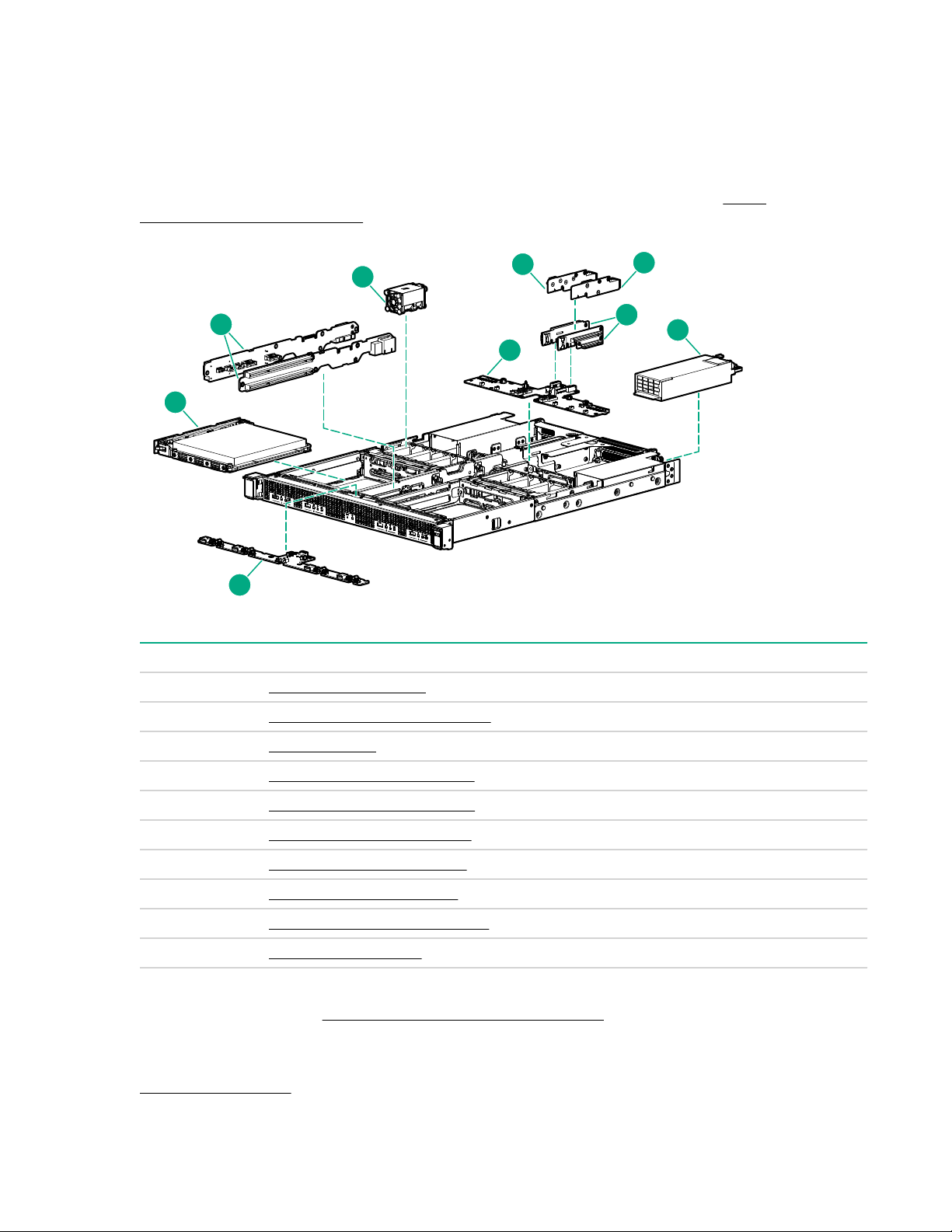
Illustrated parts catalog
1
2
3
4
5
6
7
8
9
System components for PCIe configuration
Hewlett Packard Enterprise continually improves and changes product parts. For complete and current
supported parts information, see the Hewlett Packard Enterprise PartSurfer website (
www.hpe.com/info/partssurfer).
http://
Item Description
1 Cartridge spare parts on page 6
2 Cartridge rail card spare parts on page 7
3 Fan spare part on page 7
4 Baseboard PCA spare parts on page 7
5 QSFP+ riser card spare part on page 7
6 SFP+ riser card spare parts on page 7
7 PCIe riser card spare parts on page 7
8 Power supply spare parts on page 8
9 Front panel board spare parts on page 8
10 Cable kit spare parts on page 8
1
Not shown
For more information, see Removal and replacement procedures on page 21.
1
Cartridge spare parts
Customer self repair: Optional
6 Illustrated parts catalog
Page 7

For information on supported cartridges, see the product QuickSpecs on the Hewlett Packard Enterprise
website (http://www.hpe.com/info/qs).
Cartridge rail card spare parts
Customer self repair: Optional
Description Spare part number
Cartridge rail cards (left and right) 867514-001
Fan spare part
Customer self repair: Mandatory
Description Spare part number
Fan module 867532-001
Baseboard PCA spare parts
Customer self repair: Optional
Description Spare part number
HPE EL4000 PassThru baseboard PCA 867520-001
HPE EL4000 Switch baseboard PCA 867524-001
QSFP+ riser card spare part
Customer self repair: Optional
The QSFP+ riser card is supported only on the HPE Edgeline EL4000 PassThru System.
Description Spare part number
QSFP+ riser card V2 867531-001
SFP+ riser card spare parts
Customer self repair: Optional
The SFP+ riser card is supported only on the HPE Edgeline EL4000 Switch System.
Description Spare part number
SFP+ riser card 867530-001
PCIe riser card spare parts
Customer self repair: Optional
Description Spare part number
PCIe riser card, left 867526-001
PCIe riser card, right 867527-001
Cartridge rail card spare parts 7
Page 8

Power supply spare parts
Customer self repair: Mandatory
Description Spare part number
800W Flex Slot -48VDC Hot Plug Power Supply 754382-001
800W Flex Slot Platinum Plus Hot Plug Power
Supply
Front panel board spare parts
Customer self repair: Optional
Description Spare part number
Front panel board 867512-001
Cable kit spare parts
Customer self repair: Optional
Description Spare part number
EL4000 cable kit.
Includes the following:
• Left cable harness assembly
• Front panel cable assembly
• Cable front I/O USB assembly
• Right cable harness PCIe assembly
• EL4000 RJ45 cable assembly
754381-001
867736-001
USB to Serial cable assembly kit 872326-001
System components for PXIe configuration
Hewlett Packard Enterprise continually improves and changes product parts. For complete and current
supported parts information, see the Hewlett Packard Enterprise PartSurfer website (http://
www.hpe.com/info/partssurfer).
8 Power supply spare parts
Page 9

1
3
5
4
6
7
2
Item Description
1 Cartridge spare parts on page 6
2 Cartridge rail card spare parts on page 9
3 Fan spare part on page 7
4 PXIe riser board spare parts on page 10
5 Baseboard PCA spare part on page 10
6 Power supply spare parts on page 8
7 Front panel board spare part on page 10
8 Cable kit spare parts on page 10
1
Not shown
For more information, see Removal and replacement procedures on page 21.
Cartridge spare parts
Customer self repair: Optional
1
1
For information on supported cartridges, see the product QuickSpecs on the Hewlett Packard Enterprise
website (http://www.hpe.com/info/qs).
Cartridge rail card spare parts
Customer self repair: Optional
Description Spare part number
Cartridge rail card (left and right) 867518-001
Cartridge spare parts 9
Page 10

Fan spare part
Customer self repair: Mandatory
Description Spare part number
Fan module 867532-001
PXIe riser board spare parts
Customer self repair: Mandatory
Description Spare part number
PXIe riser board assembly 867529-001
Baseboard PCA spare part
Customer self repair: Optional
Description Spare part number
HPE EL4000 Instrumentation baseboard PCA 867525-001
Power supply spare parts
Customer self repair: Mandatory
Description Spare part number
800W Flex Slot -48VDC Hot Plug Power Supply 754382-001
800W Flex Slot Platinum Plus Hot Plug Power
Supply
Front panel board spare part
Customer self repair: Optional
Description Spare part number
Front panel board 867513-001
Cable kit spare parts
Customer self repair: Optional
754381-001
10 Fan spare part
Page 11

Description Spare part number
EL4000 Instrumentation cable kit.
Includes the following:
• Front I/O to system board SAS cable (x8, 12G)
assembly
• UID to main baseboard cable assembly
• Cable front I/O USB assembly
• Rail board to system board, right SAS cable (x8,
12G) assembly
• Rail board to system board, left SAS cable (x8,
12G) assembly
• Front bezel to system board SMA cable
assembly
• Power cable assembly
USB to Serial cable assembly kit 872326-001
869163-001
Illustrated parts catalog 11
Page 12

Customer self repair
Hewlett Packard Enterprise products are designed with many Customer Self Repair (CSR) parts to
minimize repair time and allow for greater flexibility in performing defective parts replacement. If during
the diagnosis period Hewlett Packard Enterprise (or Hewlett Packard Enterprise service providers or
service partners) identifies that the repair can be accomplished by the use of a CSR part, Hewlett
Packard Enterprise will ship that part directly to you for replacement. There are two categories of CSR
parts:
• Mandatory—Parts for which customer self repair is mandatory. If you request Hewlett Packard
Enterprise to replace these parts, you will be charged for the travel and labor costs of this service.
• Optional—Parts for which customer self repair is optional. These parts are also designed for customer
self repair. If, however, you require that Hewlett Packard Enterprise replace them for you, there may or
may not be additional charges, depending on the type of warranty service designated for your product.
NOTE: Some Hewlett Packard Enterprise parts are not designed for customer self repair. In order to
satisfy the customer warranty, Hewlett Packard Enterprise requires that an authorized service
provider replace the part. These parts are identified as "No" in the Illustrated Parts Catalog.
Based on availability and where geography permits, CSR parts will be shipped for next business day
delivery. Same day or four-hour delivery may be offered at an additional charge where geography
permits. If assistance is required, you can call the Hewlett Packard Enterprise Support Center and a
technician will help you over the telephone. Hewlett Packard Enterprise specifies in the materials shipped
with a replacement CSR part whether a defective part must be returned to Hewlett Packard Enterprise. In
cases where it is required to return the defective part to Hewlett Packard Enterprise, you must ship the
defective part back to Hewlett Packard Enterprise within a defined period of time, normally five (5)
business days. The defective part must be returned with the associated documentation in the provided
shipping material. Failure to return the defective part may result in Hewlett Packard Enterprise billing you
for the replacement. With a customer self repair, Hewlett Packard Enterprise will pay all shipping and part
return costs and determine the courier/carrier to be used.
For more information about the Hewlett Packard Enterprise CSR program, contact your local service
provider. For the North American program, go to the Hewlett Packard Enterprise CSR website
Parts only warranty service
Your Hewlett Packard Enterprise Limited Warranty may include a parts only warranty service. Under the
terms of parts only warranty service, Hewlett Packard Enterprise will provide replacement parts free of
charge.
For parts only warranty service, CSR part replacement is mandatory. If you request Hewlett Packard
Enterprise to replace these parts, you will be charged for the travel and labor costs of this service.
Réparation par le client (CSR)
Les produits Hewlett Packard Enterprise comportent de nombreuses pièces CSR (Customer Self Repair
= réparation par le client) afin de minimiser les délais de réparation et faciliter le remplacement des
pièces défectueuses. Si pendant la période de diagnostic, Hewlett Packard Enterprise (ou ses
partenaires ou mainteneurs agréés) détermine que la réparation peut être effectuée à l'aide d'une pièce
CSR, Hewlett Packard Enterprise vous l'envoie directement. Il existe deux catégories de pièces CSR :
• Obligatoire—Pièces pour lesquelles la réparation par le client est obligatoire. Si vous demandez à
Hewlett Packard Enterprise de remplacer ces pièces, les coûts de déplacement et main d'œuvre du
service vous seront facturés.
• Facultatif—Pièces pour lesquelles la réparation par le client est facultative. Ces pièces sont
également conçues pour permettre au client d'effectuer lui-même la réparation. Toutefois, si vous
12 Customer self repair
Page 13

demandez à Hewlett Packard Enterprise de remplacer ces pièces, l'intervention peut ou non vous être
facturée, selon le type de garantie applicable à votre produit.
REMARQUE: Certaines pièces Hewlett Packard Enterprise ne sont pas conçues pour permettre au client
d'effectuer lui-même la réparation. Pour que la garantie puisse s'appliquer, Hewlett Packard Enterprise
exige que le remplacement de la pièce soit effectué par un Mainteneur Agréé. Ces pièces sont identifiées
par la mention "Non" dans le Catalogue illustré.
Les pièces CSR sont livrées le jour ouvré suivant, dans la limite des stocks disponibles et selon votre
situation géographique. Si votre situation géographique le permet et que vous demandez une livraison le
jour même ou dans les 4 heures, celle-ci vous sera facturée. Pour toute assistance, appelez le Centre
d’assistance Hewlett Packard Enterprise pour qu’un technicien vous aide au téléphone Dans les
documents envoyés avec la pièce de rechange CSR, Hewlett Packard Enterprise précise s'il est
nécessaire de lui retourner la pièce défectueuse. Si c'est le cas, vous devez le faire dans le délai indiqué,
généralement cinq (5) jours ouvrés. La pièce et sa documentation doivent être retournées dans
l'emballage fourni. Si vous ne retournez pas la pièce défectueuse, Hewlett Packard Enterprise se réserve
le droit de vous facturer les coûts de remplacement. Dans le cas d'une pièce CSR, Hewlett Packard
Enterprise supporte l'ensemble des frais d'expédition et de retour, et détermine la société de courses ou
le transporteur à utiliser.
Pour plus d'informations sur le programme CSR de Hewlett Packard Enterprise, contactez votre
Mainteneur Agrée local. Pour plus d'informations sur ce programme en Amérique du Nord, consultez le
site Web Hewlett Packard Enterprise.
Service de garantie "pièces seules"
Votre garantie limitée Hewlett Packard Enterprise peut inclure un service de garantie "pièces seules".
Dans ce cas, les pièces de rechange fournies par Hewlett Packard Enterprise ne sont pas facturées.
Dans le cadre de ce service, la réparation des pièces CSR par le client est obligatoire. Si vous demandez
à Hewlett Packard Enterprise de remplacer ces pièces, les coûts de déplacement et main d'œuvre du
service vous seront facturés.
Riparazione da parte del cliente
Per abbreviare i tempi di riparazione e garantire una maggiore flessibilità nella sostituzione di parti
difettose, i prodotti Hewlett Packard Enterprise sono realizzati con numerosi componenti che possono
essere riparati direttamente dal cliente (CSR, Customer Self Repair). Se in fase di diagnostica Hewlett
Packard Enterprise (o un centro di servizi o di assistenza Hewlett Packard Enterprise) identifica il guasto
come riparabile mediante un ricambio CSR, Hewlett Packard Enterprise lo spedirà direttamente al cliente
per la sostituzione. Vi sono due categorie di parti CSR:
• Obbligatorie—Parti che devono essere necessariamente riparate dal cliente. Se il cliente ne affida la
riparazione ad Hewlett Packard Enterprise, deve sostenere le spese di spedizione e di manodopera
per il servizio.
• Opzionali—Parti la cui riparazione da parte del cliente è facoltativa. Si tratta comunque di componenti
progettati per questo scopo. Se tuttavia il cliente ne richiede la sostituzione ad Hewlett Packard
Enterprise, potrebbe dover sostenere spese addizionali a seconda del tipo di garanzia previsto per il
prodotto.
NOTA: alcuni componenti Hewlett Packard Enterprise non sono progettati per la riparazione da parte del
cliente. Per rispettare la garanzia, Hewlett Packard Enterprise richiede che queste parti siano sostituite da
un centro di assistenza autorizzato. Tali parti sono identificate da un "No" nel Catalogo illustrato dei
componenti.
In base alla disponibilità e alla località geografica, le parti CSR vengono spedite con consegna entro il
giorno lavorativo seguente. La consegna nel giorno stesso o entro quattro ore è offerta con un
supplemento di costo solo in alcune zone. In caso di necessità si può richiedere l'assistenza telefonica di
un addetto del centro di supporto tecnico Hewlett Packard Enterprise. Nel materiale fornito con una parte
di ricambio CSR, Hewlett Packard Enterprise specifica se il cliente deve restituire dei component. Qualora
sia richiesta la resa ad Hewlett Packard Enterprise del componente difettoso, lo si deve spedire ad
Customer self repair 13
Page 14

Hewlett Packard Enterprise entro un determinato periodo di tempo, generalmente cinque (5) giorni
lavorativi. Il componente difettoso deve essere restituito con la documentazione associata nell'imballo di
spedizione fornito. La mancata restituzione del componente può comportare la fatturazione del ricambio
da parte di Hewlett Packard Enterprise. Nel caso di riparazione da parte del cliente, Hewlett Packard
Enterprise sostiene tutte le spese di spedizione e resa e sceglie il corriere/vettore da utilizzare.
Per ulteriori informazioni sul programma CSR di Hewlett Packard Enterprise, contattare il centro di
assistenza di zona. Per il programma in Nord America fare riferimento al sito Web.
Servizio di garanzia per i soli componenti
La garanzia limitata Hewlett Packard Enterprise può includere un servizio di garanzia per i soli
componenti. Nei termini di garanzia del servizio per i soli componenti, Hewlett Packard Enterprise fornirà
gratuitamente le parti di ricambio.
Per il servizio di garanzia per i soli componenti è obbligatoria la formula CSR che prevede la riparazione
da parte del cliente. Se il cliente invece richiede la sostituzione ad Hewlett Packard Enterprise dovrà
sostenere le spese di spedizione e di manodopera per il servizio.
Customer Self Repair
Hewlett Packard Enterprise Produkte enthalten viele CSR-Teile (Customer Self Repair), um
Reparaturzeiten zu minimieren und höhere Flexibilität beim Austausch defekter Bauteile zu ermöglichen.
Wenn Hewlett Packard Enterprise (oder ein Hewlett Packard Enterprise Servicepartner) bei der Diagnose
feststellt, dass das Produkt mithilfe eines CSR-Teils repariert werden kann, sendet Ihnen Hewlett Packard
Enterprise dieses Bauteil zum Austausch direkt zu. CSR-Teile werden in zwei Kategorien unterteilt:
• Zwingend—Teile, für die das Customer Self Repair-Verfahren zwingend vorgegeben ist. Wenn Sie
den Austausch dieser Teile von Hewlett Packard Enterprise vornehmen lassen, werden Ihnen die
Anfahrt- und Arbeitskosten für diesen Service berechnet.
• Optional—Teile, für die das Customer Self Repair-Verfahren optional ist. Diese Teile sind auch für
Customer Self Repair ausgelegt. Wenn Sie jedoch den Austausch dieser Teile von Hewlett Packard
Enterprise vornehmen lassen möchten, können bei diesem Service je nach den für Ihr Produkt
vorgesehenen Garantiebedingungen zusätzliche Kosten anfallen.
HINWEIS: Einige Hewlett Packard Enterprise Teile sind nicht für Customer Self Repair ausgelegt. Um den
Garantieanspruch des Kunden zu erfüllen, muss das Teil von einem Hewlett Packard Enterprise
Servicepartner ersetzt werden. Im illustrierten Teilekatalog sind diese Teile mit „No“ bzw.
„Nein“ gekennzeichnet.
CSR-Teile werden abhängig von der Verfügbarkeit und vom Lieferziel am folgenden Geschäftstag
geliefert. Für bestimmte Standorte ist eine Lieferung am selben Tag oder innerhalb von vier Stunden
gegen einen Aufpreis verfügbar. Wenn Sie Hilfe benötigen, können Sie das Hewlett Packard Enterprise
Support Center anrufen und sich von einem Mitarbeiter per Telefon helfen lassen. Den Materialien von
Hewlett Packard Enterprise, die mit einem CSR-Ersatzteil geliefert werden, können Sie entnehmen, ob
das defekte Teil an Hewlett Packard Enterprise zurückgeschickt werden muss. Wenn es erforderlich ist,
das defekte Teil an Hewlett Packard Enterprise zurückzuschicken, müssen Sie dies innerhalb eines
vorgegebenen Zeitraums tun, in der Regel innerhalb von fünf (5) Geschäftstagen. Das defekte Teil muss
mit der zugehörigen Dokumentation in der Verpackung zurückgeschickt werden, die im Lieferumfang
enthalten ist. Wenn Sie das defekte Teil nicht zurückschicken, kann Hewlett Packard Enterprise Ihnen das
Ersatzteil in Rechnung stellen. Im Falle von Customer Self Repair kommt Hewlett Packard Enterprise für
alle Kosten für die Lieferung und Rücksendung auf und bestimmt den Kurier-/Frachtdienst.
Weitere Informationen über das Hewlett Packard Enterprise Customer Self Repair Programm erhalten Sie
von Ihrem Servicepartner vor Ort. Informationen über das CSR-Programm in Nordamerika finden Sie auf
der Hewlett Packard Enterprise Website unter.
14 Customer self repair
Page 15

Parts-only Warranty Service (Garantieservice ausschließlich für Teile)
Ihre Hewlett Packard Enterprise Garantie umfasst möglicherweise einen Parts-only Warranty Service
(Garantieservice ausschließlich für Teile). Gemäß den Bestimmungen des Parts-only Warranty Service
stellt Hewlett Packard Enterprise Ersatzteile kostenlos zur Verfügung.
Für den Parts-only Warranty Service ist das CSR-Verfahren zwingend vorgegeben. Wenn Sie den
Austausch dieser Teile von Hewlett Packard Enterprise vornehmen lassen, werden Ihnen die Anfahrt- und
Arbeitskosten für diesen Service berechnet.
Reparaciones del propio cliente
Los productos de Hewlett Packard Enterprise incluyen muchos componentes que el propio usuario puede
reemplazar (Customer Self Repair, CSR) para minimizar el tiempo de reparación y ofrecer una mayor
flexibilidad a la hora de realizar sustituciones de componentes defectuosos. Si, durante la fase de
diagnóstico, Hewlett Packard Enterprise (o los proveedores o socios de servicio de Hewlett Packard
Enterprise) identifica que una reparación puede llevarse a cabo mediante el uso de un componente CSR,
Hewlett Packard Enterprise le enviará dicho componente directamente para que realice su sustitución.
Los componentes CSR se clasifican en dos categorías:
• Obligatorio—Componentes cuya reparación por parte del usuario es obligatoria. Si solicita a Hewlett
Packard Enterprise que realice la sustitución de estos componentes, tendrá que hacerse cargo de los
gastos de desplazamiento y de mano de obra de dicho servicio.
• Opcional—Componentes cuya reparación por parte del usuario es opcional. Estos componentes
también están diseñados para que puedan ser reparados por el usuario. Sin embargo, si precisa que
Hewlett Packard Enterprise realice su sustitución, puede o no conllevar costes adicionales,
dependiendo del tipo de servicio de garantía correspondiente al producto.
NOTA: Algunos componentes de Hewlett Packard Enterprise no están diseñados para que puedan ser
reparados por el usuario. Para que el usuario haga valer su garantía, Hewlett Packard Enterprise pone
como condición que un proveedor de servicios autorizado realice la sustitución de estos componentes.
Dichos componentes se identifican con la palabra "No" en el catálogo ilustrado de componentes.
Según la disponibilidad y la situación geográfica, los componentes CSR se enviarán para que lleguen a
su destino al siguiente día laborable. Si la situación geográfica lo permite, se puede solicitar la entrega en
el mismo día o en cuatro horas con un coste adicional. Si precisa asistencia técnica, puede llamar al
Centro de asistencia técnica de Hewlett Packard Enterprise y recibirá ayuda telefónica por parte de un
técnico. Con el envío de materiales para la sustitución de componentes CSR, Hewlett Packard Enterprise
especificará si los componentes defectuosos deberán devolverse a Hewlett Packard Enterprise. En
aquellos casos en los que sea necesario devolver algún componente a Hewlett Packard Enterprise,
deberá hacerlo en el periodo de tiempo especificado, normalmente cinco días laborables. Los
componentes defectuosos deberán devolverse con toda la documentación relacionada y con el embalaje
de envío. Si no enviara el componente defectuoso requerido, Hewlett Packard Enterprise podrá cobrarle
por el de sustitución. En el caso de todas sustituciones que lleve a cabo el cliente, Hewlett Packard
Enterprise se hará cargo de todos los gastos de envío y devolución de componentes y escogerá la
empresa de transporte que se utilice para dicho servicio.
Para obtener más información acerca del programa de Reparaciones del propio cliente de Hewlett
Packard Enterprise, póngase en contacto con su proveedor de servicios local. Si está interesado en el
programa para Norteamérica, visite la página web de Hewlett Packard Enterprise CSR.
Servicio de garantía exclusivo de componentes
La garantía limitada de Hewlett Packard Enterprise puede que incluya un servicio de garantía exclusivo
de componentes. Según las condiciones de este servicio exclusivo de componentes, Hewlett Packard
Enterprise le facilitará los componentes de repuesto sin cargo adicional alguno.
Para este servicio de garantía exclusivo de componentes, es obligatoria la sustitución de componentes
por parte del usuario (CSR). Si solicita a Hewlett Packard Enterprise que realice la sustitución de estos
componentes, tendrá que hacerse cargo de los gastos de desplazamiento y de mano de obra de dicho
servicio.
Customer self repair 15
Page 16

Customer Self Repair
Veel onderdelen in Hewlett Packard Enterprise producten zijn door de klant zelf te repareren, waardoor
de reparatieduur tot een minimum beperkt kan blijven en de flexibiliteit in het vervangen van defecte
onderdelen groter is. Deze onderdelen worden CSR-onderdelen (Customer Self Repair) genoemd. Als
Hewlett Packard Enterprise (of een Hewlett Packard Enterprise Service Partner) bij de diagnose vaststelt
dat de reparatie kan worden uitgevoerd met een CSR-onderdeel, verzendt Hewlett Packard Enterprise
dat onderdeel rechtstreeks naar u, zodat u het defecte onderdeel daarmee kunt vervangen. Er zijn twee
categorieën CSR-onderdelen:
• Verplicht—Onderdelen waarvoor reparatie door de klant verplicht is. Als u Hewlett Packard Enterprise
verzoekt deze onderdelen voor u te vervangen, worden u voor deze service reiskosten en arbeidsloon
in rekening gebracht.
• Optioneel—Onderdelen waarvoor reparatie door de klant optioneel is. Ook deze onderdelen zijn
ontworpen voor reparatie door de klant. Als u echter Hewlett Packard Enterprise verzoekt deze
onderdelen voor u te vervangen, kunnen daarvoor extra kosten in rekening worden gebracht,
afhankelijk van het type garantieservice voor het product.
OPMERKING: Sommige Hewlett Packard Enterprise onderdelen zijn niet ontwikkeld voor reparatie door
de klant. In verband met de garantievoorwaarden moet het onderdeel door een geautoriseerde Service
Partner worden vervangen. Deze onderdelen worden in de geïllustreerde onderdelencatalogus
aangemerkt met "Nee".
Afhankelijk van de leverbaarheid en de locatie worden CSR-onderdelen verzonden voor levering op de
eerstvolgende werkdag. Levering op dezelfde dag of binnen vier uur kan tegen meerkosten worden
aangeboden, indien dit mogelijk is gezien de locatie. Indien assistentie is gewenst, belt u het Hewlett
Packard Enterprise Support Center om via de telefoon ondersteuning van een technicus te ontvangen.
Hewlett Packard Enterprise vermeldt in de documentatie bij het vervangende CSR-onderdeel of het
defecte onderdeel aan Hewlett Packard Enterprise moet worden geretourneerd. Als het defecte
onderdeel aan Hewlett Packard Enterprise moet worden teruggezonden, moet u het defecte onderdeel
binnen een bepaalde periode, gewoonlijk vijf (5) werkdagen, retourneren aan Hewlett Packard Enterprise.
Het defecte onderdeel moet met de bijbehorende documentatie worden geretourneerd in het
meegeleverde verpakkingsmateriaal. Als u het defecte onderdeel niet terugzendt, kan Hewlett Packard
Enterprise u voor het vervangende onderdeel kosten in rekening brengen. Bij reparatie door de klant
betaalt Hewlett Packard Enterprise alle verzendkosten voor het vervangende en geretourneerde
onderdeel en kiest Hewlett Packard Enterprise zelf welke koerier/transportonderneming hiervoor wordt
gebruikt.
Neem contact op met een Service Partner voor meer informatie over het Customer Self Repair
programma van Hewlett Packard Enterprise. Informatie over Service Partners vindt u op de Hewlett
Packard Enterprise website.
Garantieservice "Parts Only"
Het is mogelijk dat de Hewlett Packard Enterprise garantie alleen de garantieservice "Parts Only" omvat.
Volgens de bepalingen van de Parts Only garantieservice zal Hewlett Packard Enterprise kosteloos
vervangende onderdelen ter beschikking stellen.
Voor de Parts Only garantieservice is vervanging door CSR-onderdelen verplicht. Als u Hewlett Packard
Enterprise verzoekt deze onderdelen voor u te vervangen, worden u voor deze service reiskosten en
arbeidsloon in rekening gebracht
Reparo feito pelo cliente
Os produtos da Hewlett Packard Enterprise são projetados com muitas peças para reparo feito pelo
cliente (CSR) de modo a minimizar o tempo de reparo e permitir maior flexibilidade na substituição de
peças com defeito. Se, durante o período de diagnóstico, a Hewlett Packard Enterprise (ou fornecedores/
parceiros da Hewlett Packard Enterprise) concluir que o reparo pode ser efetuado pelo uso de uma peça
CSR, a Hewlett Packard Enterprise enviará a peça diretamente ao cliente. Há duas categorias de peças
CSR:
16 Customer self repair
Page 17

• Obrigatória—Peças cujo reparo feito pelo cliente é obrigatório. Se desejar que a Hewlett Packard
Enterprise substitua essas peças, serão cobradas as despesas de transporte e mão-de-obra do
serviço.
• Opcional—Peças cujo reparo feito pelo cliente é opcional. Essas peças também são projetadas para
o reparo feito pelo cliente. No entanto, se desejar que a Hewlett Packard Enterprise as substitua,
pode haver ou não a cobrança de taxa adicional, dependendo do tipo de serviço de garantia
destinado ao produto.
OBSERVAÇÃO: Algumas peças da Hewlett Packard Enterprise não são projetadas para o reparo feito
pelo cliente. A fim de cumprir a garantia do cliente, a Hewlett Packard Enterprise exige que um técnico
autorizado substitua a peça. Essas peças estão identificadas com a marca "No" (Não), no catálogo de
peças ilustrado.
Conforme a disponibilidade e o local geográfico, as peças CSR serão enviadas no primeiro dia útil após
o pedido. Onde as condições geográficas permitirem, a entrega no mesmo dia ou em quatro horas pode
ser feita mediante uma taxa adicional. Se precisar de auxílio, entre em contato com o Centro de suporte
técnico da Hewlett Packard Enterprise para que um técnico o ajude por telefone. A Hewlett Packard
Enterprise especifica nos materiais fornecidos com a peça CSR de reposição se a peça com defeito deve
ser devolvida à Hewlett Packard Enterprise. Nos casos em que isso for necessário, é preciso enviar a
peça com defeito à Hewlett Packard Enterprise, você deverá enviar a peça com defeito de volta para a
Hewlett Packard Enterprise dentro do período de tempo definido, normalmente em 5 (cinco) dias úteis. A
peça com defeito deve ser enviada com a documentação correspondente no material de transporte
fornecido. Caso não o faça, a Hewlett Packard Enterprise poderá cobrar a reposição. Para as peças de
reparo feito pelo cliente, a Hewlett Packard Enterprise paga todas as despesas de transporte e de
devolução da peça e determina a transportadora/serviço postal a ser utilizado.
Para obter mais informações sobre o programa de reparo feito pelo cliente da Hewlett Packard
Enterprise, entre em contato com o fornecedor de serviços local. Para o programa norte-americano,
visite o site da Hewlett Packard Enterprise.
Serviço de garantia apenas para peças
A garantia limitada da Hewlett Packard Enterprise pode incluir um serviço de garantia apenas para
peças. Segundo os termos do serviço de garantia apenas para peças, a Hewlett Packard Enterprise
fornece as peças de reposição sem cobrar nenhuma taxa.
No caso desse serviço, a substituição de peças CSR é obrigatória. Se desejar que a Hewlett Packard
Enterprise substitua essas peças, serão cobradas as despesas de transporte e mão-de-obra do serviço.
Customer self repair 17
Page 18
18 Customer self repair
Page 19
Customer self repair 19
Page 20
20 Customer self repair
Page 21

Removal and replacement procedures
Required tools
You need the following items for some procedures:
• T-10 Torx screwdriver
• T-15 Torx screwdriver
• Phillips screwdriver
Safety considerations
Before performing service procedures, review all the safety information.
Preventing electrostatic discharge
About this task
To prevent damaging the system, be aware of the precautions you must follow when setting up the
system or handling parts. A discharge of static electricity from a finger or other conductor may damage
system boards or other static-sensitive devices. This type of damage may reduce the life expectancy of
the device.
Procedure
• Avoid hand contact by transporting and storing products in static-safe containers.
• Keep electrostatic-sensitive parts in their containers until they arrive at static-free workstations.
• Place parts on a grounded surface before removing them from their containers.
• Avoid touching pins, leads, or circuitry.
• Always be properly grounded when touching a static-sensitive component or assembly.
Symbols on equipment
The following symbols might be found on the equipment to indicate the presence of potentially hazardous
conditions.
This symbol indicates the presence of hazardous energy circuits or electric shock
hazards. Refer all servicing to qualified personnel.
WARNING: To reduce the risk of injury from electric shock hazards, do not open this
enclosure. Refer all maintenance, upgrades, and servicing to qualified personnel.
This symbol indicates the presence of electric shock hazards. The area contains no
user or field serviceable parts. Do not open for any reason.
WARNING: To reduce the risk of injury from electric shock hazards, do not open this
enclosure.
This symbol on an RJ-45 receptacle indicates a network interface connection.
WARNING: To reduce the risk of electric shock, fire, or damage to the equipment, do
not plug telephone or telecommunications connectors into this receptacle.
Removal and replacement procedures 21
Page 22

This symbol indicates the presence of a hot surface or hot component. If this surface is
14 kg
30.86 lb
contacted, the potential for injury exists.
WARNING: To reduce the risk of injury from a hot component, allow the surface to cool
before touching.
This symbol indicates that the component exceeds the recommended weight for one
individual to handle safely.
WARNING: To reduce the risk of personal injury or damage to the equipment,
observe local occupational health and safety requirements and guidelines for manual
material handling.
These symbols, on power supplies or systems, indicate that the equipment is supplied
by multiple sources of power.
WARNING: To reduce the risk of injury from electric shock, remove all power cords to
disconnect power from the system completely.
System warnings and cautions
Before installing a system, be sure that you understand the following warnings and cautions.
WARNING:
To reduce the risk of electric shock or damage to the equipment:
• Do not disable the power cord grounding plug. The grounding plug is an important safety feature.
• Plug the power cord into a grounded (earthed) electrical outlet that is easily accessible at all
times.
• Unplug the power cord from the power supply to disconnect power to the equipment.
• Do not route the power cord where it can be walked on or pinched by items placed against it.
Pay particular attention to the plug, electrical outlet, and the point where the cord extends from
the system.
WARNING:
To reduce the risk of personal injury from hot surfaces, allow the drives and the internal system
components to cool before touching them.
CAUTION:
Do not operate the system for long periods with the access panel open or removed. Operating the
system in this manner results in improper airflow and improper cooling that can lead to thermal
damage.
Preparing to remove or replace components
About this task
For performing certain service procedures and accessing some components, you must perform one or
more of the following procedures.
Procedure
1. Powering down the system
22 System warnings and cautions
Page 23

If you must dismount the system or remove a non-hot-plug component, then you must power down the
system.
2. Dismounting the system
If the environment, cabling configuration, or the system location creates unstable conditions, then
dismount the system and place it on a stable surface.
3. Removing the access panel
4. Removing the fixed top cover
Power down the system
About this task
Before powering down the system for any upgrade or maintenance procedures, back up critical system
data and programs.
Before performing chassis maintenance, shut down all cartridges installed in the system.
Procedure
• Use one of the following methods to power down the system:
◦ Press and release the Power On/Standby button of the cartridges installed in the system.
This method initiates a controlled shutdown of applications and the OS before the system enters
standby mode.
◦ Press and hold the Power On/Standby button of the cartridges installed in the system for more than
4 seconds to force the system to power down.
This method forces the system to power down without properly exiting applications and the OS. If
an application stops responding, you can use this method to force a shutdown.
Verify the system is in standby mode and the system power LED is off.
Dismount the system
About this task
Dismount the system, based on the mount installed:
• Dismount the system from a wall mount
• Dismount the system from a rack mount
Remove the access panel
Depending on the configuration of your system, perform one of the following procedures:
• Removing the PCIe access panel on page 23
• Removing the PXIe access panel on page 24
Removing the PCIe access panel
Procedure
1. Using a Torx screwdriver, turn the T-15 locking Torx screw a quarter turn to unlock the latch.
2. Press the latch button and open the latch.
3. Remove the access panel.
Power down the system 23
Page 24

Removing the PXIe access panel
2
1
Procedure
1. Press the latch button and open the latch.
2. Slide the panel to the rear of the chassis.
3. Lift and remove the access panel.
Remove the fixed top cover
Depending on the configuration of your system, perform one or more of the following procedures:
• Removing the fixed top cover of the PCIe system on page 25
• Removing the fixed front top cover of the PXIe system on page 25
• Removing the fixed rear top cover of the PXIe system on page 25
24 Removing the PXIe access panel
Page 25

Removing the fixed top cover of the PCIe system
1
2
1
1
1
1
1
1
1
1
Procedure
1. Using a Torx screwdriver, remove the nine T-10 Torx screws securing the fixed top cover to the
system.
Removing the fixed front top cover of the PXIe system
Procedure
1. Using a Torx screwdriver, remove the 10 T-10 Torx screws securing the fixed front top cover to the
system.
Removing the fixed rear top cover of the PXIe system
Procedure
1. Remove the PXIe access panel (Removing the PXIe access panel on page 24).
2. Using a Torx screwdriver, remove the 14 T-10 Torx screws securing the fixed rear top cover to the
system.
Removing the fixed top cover of the PCIe system 25
Page 26

1
1
1
2
1
Remove the PCIe riser assembly
• Removing the left PCIe riser assembly on page 26
• Removing the right PCIe riser assembly on page 27
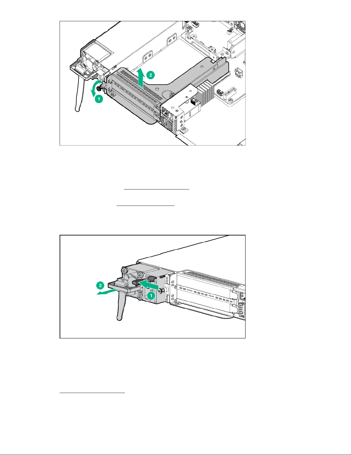
Removing the left PCIe riser assembly
Procedure
1. Power down the system (Power down the system on page 23).
2. Dismount the system (Dismount the system on page 23).
3. Remove the access panel (Removing the PCIe access panel on page 23).
4. Disconnect the two cables from the left PCIe riser assembly.
5. Using a Torx screwdriver, unscrew the captive T-15 screw and remove the left PCIe riser assembly.
26 Remove the PCIe riser assembly
Page 27

Removing the right PCIe riser assembly
Procedure
1. Power down the system (Power down the system on page 23).
2. Dismount the system (Dismount the system on page 23).
3. Remove the access panel (Removing the PCIe access panel on page 23).
4. Disconnect the two cables from the right PCIe riser assembly.
5. Using a Torx screwdriver, unscrew the captive T-15 screw and remove the right PCIe riser assembly.
Removing the right PCIe riser assembly 27
Page 28
Removing and replacing an AC power supply
Procedure
1. Power down the system (Power down the system on page 23).
This action is required only if you have a single power supply in the system.
2. Dismount the system (Dismount the system on page 23).
This action is required only if you have a single power supply in the system.
3. Unwrap the cable tie wrap and disconnect the power cord from the power supply.
4. Press the power supply release lever and remove the power supply.
To replace the component, reverse the removal procedure.
Removing and replacing a DC power supply
Procedure
1. Power down the system.
2. Remove the cable tie wrap and disconnect the power cord from the power source.
3. Press the power supply release lever and remove the power supply.
28 Removing and replacing an AC power supply
Page 29

4. Remove the ground cable from the top of the power supply.
5. Remove the connector from the rear of the power supply.
To replace the component, reverse the removal procedure.
Removal and replacement procedures 29
Page 30

Removing and replacing a power supply blank
Procedure
1. Remove the component as indicated.
To replace the component, reverse the removal procedure.
Removing and replacing a system battery
About this task
If the system no longer automatically displays the correct date and time, then replace the battery that
provides power to the real-time clock. Under normal use, battery life is 5 to 10 years.
WARNING:
The computer contains an internal lithium manganese dioxide, a vanadium pentoxide, or an alkaline
battery pack. A risk of fire and burns exists if the battery pack is not properly handled. To reduce the
risk of personal injury:
• Do not attempt to recharge the battery.
• Do not expose the battery to temperatures higher than 60°C (140°F).
• Do not disassemble, crush, puncture, short external contacts, or dispose of in fire or water.
• Replace only with the spare designated for this product.
Procedure
1. Power down the system (Power down the system on page 23).
2. Dismount the system (Dismount the system on page 23).
3. Place the system on a flat, level work surface.
4. Remove the access panel (Remove the access panel on page 23).
5. Locate the battery on the system board:
• System board components (PCIe) on page 48
• System board components (PXIe) on page 52
6. Remove the battery.
30 Removing and replacing a power supply blank
Page 31

IMPORTANT:
Replacing the system board battery resets the system ROM to its default configuration. After
replacing the battery, reconfigure the system through UEFI System Utilities.
To replace the component, reverse the removal procedure.
For more information about battery replacement or proper disposal, contact an authorized reseller or an
authorized service provider.
Removing and replacing a fan
Procedure
1. Power down the system (Power down the system on page 23).
2. Dismount the system (Dismount the system on page 23).
3. Remove the access panel (Remove the access panel on page 23).
4. Disconnect the fan cable from the board and remove the fan.
Removing and replacing a fan 31
Page 32

To replace the component, reverse the removal procedure.
Removing and replacing the cartridge
Procedure
1. Power down the system (Power down the system on page 23).
2. Dismount the system (Dismount the system on page 23), if necessary.
3. Push latch on cover.
4. Pull cover up and slide back.
5. Press the cartridge latch buttons and open the latches.
6. Remove the cartridge.*
To replace the component, reverse the removal procedure.
*Cartridges placed into slots 3 and 4 will appear upside down from image.
Cartridge components
For the following, see the cartridge user and maintenance guide on the Hewlett Packard Enterprise
website (http://www.hpe.com/info/edgeline-docs).
• Memory configuration and replacement
• Heatsink replacement
Removing and replacing the front panel board
Depending on your system configuration, perform one of the following procedures:
• Remove and replace the front panel board for the PCIe configuration on page 32
• Remove and replace the front panel board for the PXIe configuration on page 34
Remove and replace the front panel board for the PCIe configuration
Procedure
1. Power down the system (Power down the system on page 23).
2. Dismount the system (Dismount the system on page 23).
3. Remove the fixed top cover (Removing the fixed top cover of the PCIe system on page 25).
4. Using a Torx screwdriver, remove the four T-10 Torx screws and remove the front-end bezel.
32 Removing and replacing the cartridge
Page 33

1
1
1
1
2
5. Disconnect the cables from the rail board assembly.
6. Using a Torx screwdriver, remove six T-15 Torx screws and remove the front panel board.
Removal and replacement procedures 33
Page 34

To replace the component, reverse the removal procedure.
2
1
1
1
1
Remove and replace the front panel board for the PXIe configuration
Procedure
1. Power down the system (Power down the system on page 23).
2. Dismount the system (Dismount the system on page 23).
3. Remove the fixed front top cover (Removing the fixed front top cover of the PXIe system on page
25).
4. Disconnect any cables connected to the front panel.
5. Remove the REF IN and REF OUT clock connectors.
Note the color and location of the connectors while removing them to avoid confusion while reinstalling
them. For REF connector locations, see Front panel components on page 49.
6. Using a Torx screwdriver, remove the four T-10 Torx screws, and then remove the front-end bezel.
7. Disconnect the cables from the rail board assembly.
34 Remove and replace the front panel board for the PXIe configuration
Page 35

8. Using a Torx screwdriver, remove the six T-15 Torx screws and remove the front panel board.
1
2
1
1
1
1
To replace the component, reverse the removal procedure.
Removing and replacing the cartridge rail cards
Perform one of the following procedures depending on the configuration of your system:
• Remove and replace the cartridge rail cards in a PCIe system on page 35
• Remove and replace the cartridge rail cards in a PXIe system on page 37
Remove and replace the cartridge rail cards in a PCIe system
Procedure
1. Power down the system (Power down the system on page 23).
2. Dismount the system (Dismount the system on page 23).
3. Remove all cartridges (Removing and replacing the cartridge on page 32).
4. Remove the access panel (Removing the PCIe access panel on page 23).
Removing and replacing the cartridge rail cards 35
Page 36

5. Remove the fixed top cover (Removing the fixed top cover of the PCIe system on page 25).
6. Disconnect all cables from the rail cards.
7. Using a Torx screwdriver, remove the two T-15 screws from both the left and right rail card retention
brackets and remove the brackets.
8. Using a Torx screwdriver, unscrew the eight captive T-15 screws, and then remove the rail cards.
36 Removal and replacement procedures
Page 37

To replace the component, reverse the removal procedure.
Remove and replace the cartridge rail cards in a PXIe system
Procedure
1. Power down the system (Power down the system on page 23).
2. Dismount the system (Dismount the system on page 23).
3. Remove all cartridges (Removing and replacing the cartridge on page 32).
4. Remove the access panel (Removing the PXIe access panel on page 24).
5. Remove the fixed front top cover (Removing the fixed front top cover of the PXIe system on page
25).
6. Disconnect all cables from the rail cards.
7. Using a Torx screwdriver, remove the two T-15 screws, and then remove the rail cards.
Remove and replace the cartridge rail cards in a PXIe system 37
Page 38

1
2
1
To replace the component, reverse the removal procedure.
Removing and replacing the PCIe riser cards
Perform one of the following procedures depending on the configuration of your system:
• Remove and replace the left PCIe riser card on page 38
• Remove and replace the right PCIe riser card on page 39
Remove and replace the left PCIe riser card
Procedure
1. Power down the system (Power down the system on page 23).
2. Dismount the system (Dismount the system on page 23).
3. Remove the access panel (Removing the PCIe access panel on page 23).
4. Remove the left PCI riser assembly (Removing the left PCIe riser assembly on page 26).
5. Using a Torx screwdriver, remove the three T-15 Torx screws, and then remove the PCIe riser card.
To replace the component, reverse the removal procedure.
38 Removing and replacing the PCIe riser cards
Page 39

Remove and replace the right PCIe riser card
Procedure
1. Power down the system (Power down the system on page 23).
2. Dismount the system (Dismount the system on page 23).
3. Remove the access panel (Removing the PCIe access panel on page 23).
4. Remove the right PCIe riser assembly (Removing the right PCIe riser assembly on page 27).
5. Using a Torx screwdriver, remove the three T-15 Torx screws, and then remove the PCIe riser card.
To replace the component, reverse the removal procedure.
Removing and replacing the PCIe QSFP+ riser card
About this task
The QSFP+ riser card is supported only on the HPE Edgeline EL4000 PassThru System.
Procedure
1. Power down the system (Power down the system on page 23).
2. Dismount the system (Dismount the system on page 23).
3. Remove the access panel (Removing the PCIe access panel on page 23).
4. Remove the left PCIe riser assembly (Removing the left PCIe riser assembly on page 26).
5. Remove the right PCIe riser assembly (Removing the right PCIe riser assembly on page 27).
6. Disconnect the QSFP+ riser card cable from the baseboard.
7. Using a Torx screwdriver, remove the two T-15 screws and remove the QSFP+ riser card.
Remove and replace the right PCIe riser card 39
Page 40

To replace the component, reverse the removal procedure.
Removing and replacing the PCIe SFP+ riser card
About this task
The SFP+ riser card is supported only on the HPE Edgeline EL4000 Switch System.
Procedure
1. Power down the system (Power down the system on page 23).
2. Dismount the system (Dismount the system on page 23).
3. Remove the access panel (Removing the PCIe access panel on page 23).
4. Remove the left PCIe riser assembly (Removing the left PCIe riser assembly on page 26).
5. Remove the right PCIe riser assembly (Removing the right PCIe riser assembly on page 27).
6. Disconnect the SFP+ riser card cable from the baseboard.
7. Using a Torx screwdriver, remove the two T-15 screws, and then remove the SFP+ riser card.
40 Removing and replacing the PCIe SFP+ riser card
Page 41

To replace the component, reverse the removal procedure.
Removing and replacing the PXIe riser assembly
Procedure
1. Power down the system (Power down the system on page 23).
2. Dismount the system (Dismount the system on page 23).
3. Remove the access panel (Removing the PXIe access panel on page 24).
4. Removed the fixed front top cover (Removing the fixed front top cover of the PXIe system on page
25).
5. Remove the fixed rear top cover( Removing the fixed rear top cover of the PXIe system on page
25).
6. Disconnect the cables from the PXIe riser assembly.
7. Using a Torx screwdriver, unscrew the two T-15 screws and then remove the PXIe riser assembly.
Removing and replacing the PXIe riser assembly 41
Page 42
1
2
1
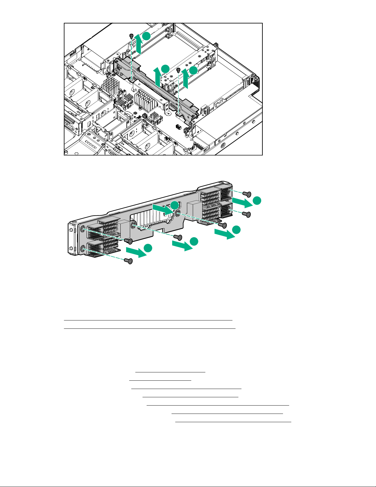
8. Using a Torx screwdriver, remove the six T-15 screws, and then remove PXIe riser board from the
1
1
2
1
1
PXIe riser assembly.
Removing and replacing the baseboard
The following procedures are for both the passthru and switch baseboards.
Perform one of the following procedures depending on the configuration of your system:
• Remove and replace the baseboard in a PCI configuration on page 42
• Remove and replace the baseboard in a PXIe configuration on page 43
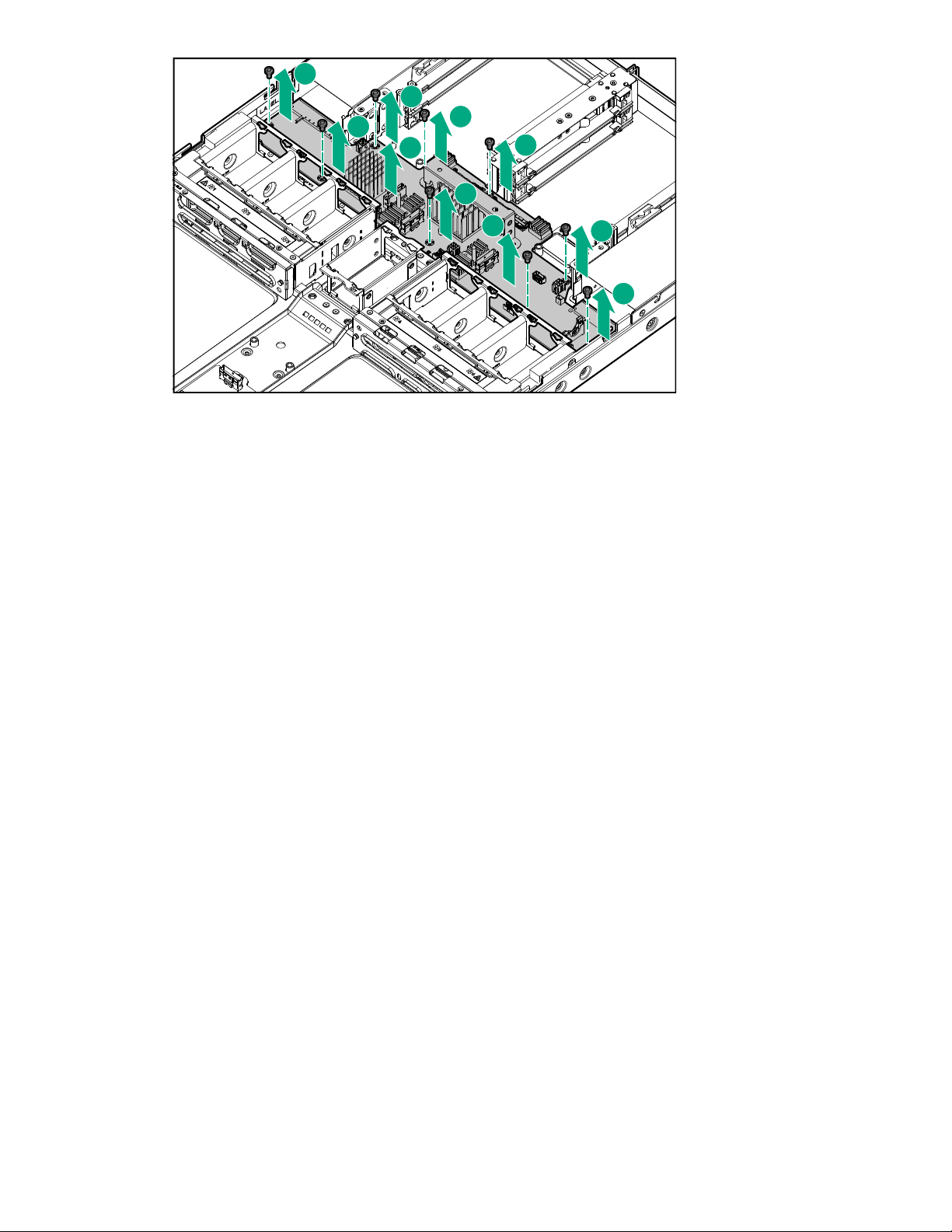
Remove and replace the baseboard in a PCI configuration
Procedure
1. Power down the system(Power down the system on page 23).
2. Dismount the system (Dismount the system on page 23).
3. Remove all cartridges (Removing and replacing the cartridge on page 32).
4. Remove the access panel (Removing the PCIe access panel on page 23).
5. Remove the fixed top cover (Removing the fixed top cover of the PCIe system on page 25).
6. Remove the left PCIe riser assembly (Removing the left PCIe riser assembly on page 26).
7. Remove the right PCIe riser assembly (Removing the right PCIe riser assembly on page 27).
8. Do one of the following:
42 Removing and replacing the baseboard
Page 43
• Remove the SFP+ riser card (Removing and replacing the PCIe SFP+ riser card on page 40).
• Remove the QSFP+ riser card (Removing and replacing the PCIe QSFP+ riser card on page
39).
9. Disconnect all cables from the baseboard.
10. Disconnect the fans (Removing and replacing a fan on page 31).
11. Remove the cartridge rail cards (Removing and replacing the cartridge rail cards on page 35).
12. Using a Torx screwdriver, remove the 12 T-15 Torx screws and remove the baseboard.
To replace the component, reverse the removal procedure.
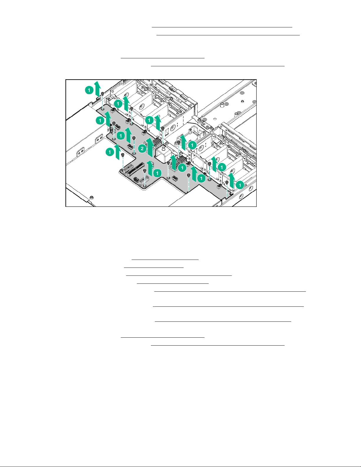
Remove and replace the baseboard in a PXIe configuration
Procedure
1. Power down the system (Power down the system on page 23).
2. Dismount the system (Dismount the system on page 23).
3. Remove all cartridges (Removing and replacing the cartridge on page 32).
4. Remove the access panel (Remove the access panel on page 23).
5. Remove the fixed front top cover (Removing the fixed front top cover of the PXIe system on page
25).
6. Remove the fixed rear top cover ( Removing the fixed rear top cover of the PXIe system on page
25).
7. Remove the PXIe riser assembly (Removing and replacing the PXIe riser assembly on page 41).
8. Disconnect all cables from the baseboard.
9. Disconnect the fans (Removing and replacing a fan on page 31).
10. Remove the cartridge rail cards (Removing and replacing the cartridge rail cards on page 35).
11. Using a Torx screwdriver, remove the nine T-15 Torx screws and remove the baseboard.
Remove and replace the baseboard in a PXIe configuration 43
Page 44
1
1
1
1
1
1
1
1
1
2
To replace the component, reverse the removal procedure.
44 Removal and replacement procedures
Page 45

Troubleshooting
HPE Edgeline Troubleshooting Guide
The HPE Edgeline System Troubleshooting Guide provides procedures for resolving common problems
and comprehensive courses of action for fault isolation and identification, issue resolution, and software
maintenance on the Edgeline System. The document is available in the
Information Library.
Hewlett Packard Enterprise
Troubleshooting 45
Page 46

Component identification
Base configurations
The HPE Edgeline EL4000 System comes in the following configurations:
• HPE Edgeline EL4000 4x10GbE 2xQSFP+ PassThru System
Supports 1 to 4 full-height, half-length PCIe cards. The core network is pass-through. A separate 1G
RJ-45 network port is provided for access to the iLO management network.
• HPE Edgeline EL4000 10GbE 2xSFP+ Switch System
Supports 1 to 4 full-height, half-length PCIe cards. The core network is Layer 2 switched. A separate
1G RJ-45 network port is provided for access to the iLO management network.
• HPE Edgeline EL4000 10GbE 2xSFP+ Switch PXIe System
Supports 1 to 4 PXIe modules. The core network is Layer 2 switched. A separate 1G RJ-45 network
port is provided for access to the iLO management network.
For identification of system components, see the following:
PCIe configuration on page 46
•
• PXIe configuration on page 49
PCIe configuration
Front panel components
Item Description
1 Cartridge 1
2 Cartridge 2
3 Cartridge 3
4 Cartridge 4
46 Component identification
Page 47

Front panel LEDs and buttons
Item Description Status
1 USB 2.0 port Connects a USB 2.0 device to the cartridge
2 Cartridge power LED/
button
3 Cartridge health LED
4 Cartridge UID LED
5 Management reset pin hole
1
button
6 Chassis system health LED
Green = Normal operation
Amber = Standby operation
Off = No power or no cartridge installed
Green = Normal operation
Flashing Amber = Degraded condition
Flashing Red = Critical condition
Off = No power or no cartridge installed
Blue = Cartridge ID is selected.
Flashing Blue = Cartridge firmware update is in progress or iLO
IRC is in use.
Off = Cartridge ID is not selected.
Pressing the reset button resets the chassis controller. iLO
remains operational.
Green = Normal operation
Flashing Amber = Degraded condition
Off = No power
1
The reset button is indented and you might need a tool, such as a pin, to press it.
Front panel LEDs and buttons 47
Page 48

Rear panel components
2
1
1 2 3 4 5 6
Item Description
1 Power supply
2 PCIe slot #4 (bottom)
3 PCIe slot #3 (top)
4 iLO port
5 Chassis UID LED
6 PCIe slot #1 (top)
7 PCIe slot #2 (bottom)
8 Power supply
9 QSFP+ Uplink B or SFP+ Uplink B
10 QSFP+ Uplink A or SFP+ Uplink A
1
Rear components include either QSFP+ or SFP+ ports, depending on configuration.
System board components (PCIe)
1
1
48 Rear panel components
Page 49

Item Description
3 4
1 2
1 2 8 93 4 5 6 7
1 System battery
2 System board
Cartridge slot identification
Item Description
1 Left side, top—Cartridge 1
2 Left side, bottom—Cartridge 2
3 Right side, top—Cartridge 3
4 Right side, bottom—Cartridge 4
PXIe configuration
Front panel components
Item Description
1 Cartridge 1
2 Cartridge 2
3 10 MHz REF OUT clock
4 SFP+ Uplink A connector
5 SFP+ Uplink B connector
6 10 MHz REF IN clock
7 iLO connector
Table Continued
Cartridge slot identification 49
Page 50

Item Description
41 2 3 5 6
8 Cartridge 3
9 Cartridge 4
Front panel LEDs and buttons
Item Description Status
1 USB 2.0 port Connects a USB 2.0 device to the cartridge
2 Cartridge power LED/
Green = Normal operation
button
Amber = Standby operation
Off = No power or no cartridge installed
3 Cartridge health LED
Green = Normal operation
Flashing Amber = Degraded condition
Flashing Red = Critical condition
Off = No power or no cartridge installed
4 Cartridge UID LED
Blue = Cartridge ID is selected.
Flashing Blue = Cartridge firmware update is in progress or iLO
IRC is in use.
Off = Cartridge ID is not selected.
5 Management reset pin hole
1
button
6 Chassis system health LED
Pressing the reset button resets the chassis controller. iLO
remains operational.
Green = Normal operation
1
The reset button is indented and you might need a tool, such as a pin, to press it.
50 Front panel LEDs and buttons
Flashing Amber = Degraded condition
Off = No power
Page 51

Rear panel components
2
1 62 3 4 5
2
1 32
Item Description
1 Power supply 1
2 PXIe slot 4
3 PXIe slot 5
4 PXIe slot 3
5 PXIe slot 2
6 Power supply 2
Rear panel LEDs and buttons
Item Description
1 Power supply 1 LED
2 Chassis UID LED
3 Power supply 2 LED
Rear panel components 51
Page 52

System board components (PXIe)
1 32
1 2 3 475 6
3 4
1 2
Item Description
1 System board
2 DIP Switch
3 System battery
DIP switch
Position Default Function
S1 Off
Cartridge slot identification
• Off = Fan normal mode
• On = Fan high mode
Item Description
1 Left side, top—Cartridge 1
2 Left side, bottom—Cartridge 2
52 System board components (PXIe)
Table Continued
Page 53

Item Description
3 Right side, top—Cartridge 3
4 Right side, bottom—Cartridge 4
Component identification 53
Page 54

Specifications
Product QuickSpecs
For more information about product features, specifications, options, configurations, and compatibility, see
the product QuickSpecs on the
Environmental specifications
Table 1: Standard specifications
Specification Value
Temperature range
1
Hewlett Packard Enterprise website.
—
Operating
Nonoperating -30°C to 60°C (-22°F to 140°F)
Relative humidity (noncondensing) —
Operating 8% to 90% at 28°C (82.4°F) maximum wet bulb
Non-Operating 5% to 95% at 38.7°C (101.7°F) maximum wet bulb
1
All temperature ratings shown are for sea level. An altitude derating of 1.0°C per 304.8 m (1.8°F per
1,000 ft) to 3,048 m (10,000 ft) is applicable. No direct sunlight allowed. Maximum rate of change is
20°C per hour (36°F per hour).
10°C to 35°C (50°F to 95°F)
temperature
temperature
Table 2: ASHRAE Class A3 specifications
Specification Value
Temperature range
Operating
Nonoperating -30°C to 60°C (-22°F to 140°F)
Relative humidity (noncondensing)
1
—
5°C to 40°C (41°F to 104°F)
—
Operating 8% to 90% at 28°C (82.4°F) maximum wet bulb
Non-Operating 5% to 95% at 38.7°C (101.7°F) maximum wet bulb
1
All temperature ratings shown are for sea level. Good for 40°C operation up to 1,828 m (6,000 ft) with
no altitude de-rating. No restriction on product configurations. Abnormal configurations, allowed for up
to 96 hours at one time, no more than 15 days maximum per year. Operation above 40°C (104°F) up to
55°C (131°F), no altitude de-rating, 1,828 m (6,000 ft) limit. Some components could be outside the
thermal maximum limits. System must be kept running, processor throttling is allowed. Abnormal
conditions allow for operation down to -5°C (23°F).
54 Specifications
temperature
temperature
Page 55

Table 3: ASHRAE Class A4 specifications
Specification Value
Temperature range
1
—
Operating
5°C to 45°C (41°F to 113°F)
Nonoperating -30°C to 60°C (-22°F to 140°F)
Relative humidity (noncondensing)
—
Operating 8% to 90% at 28°C (82.4°F) maximum wet bulb
temperature
Non-Operating 5% to 95% at 38.7°C (101.7°F) maximum wet bulb
temperature
1
All temperature ratings shown are for sea level. An altitude derating of 1.0°C per 125 m (1.8°F per 410
ft) to 900 m (2,953 ft) is applicable. No direct sunlight allowed. Maximum rate of change is 20°C per
hour (36°F per hour). No restrictions on product configurations except for rotating hard drives. PCI cards
must be rated for continuous operation with 60°C cooling air. Not rated for operation over 3,030 m
(10,000 ft).
Table 4: Extended Edgeline specifications
Specification Value
Temperature range
Operating
Nonoperating -30°C to 60°C (-22°F to 140°F)
1
—
0°C to 55°C (32°F to 131°F)
Relative humidity (noncondensing)
—
Operating 8% to 90% at 28°C (82.4°F) maximum wet bulb
temperature
Non-Operating 5% to 95% at 38.7°C (101.7°F) maximum wet bulb
temperature
1
All temperature ratings shown are for sea level. An altitude derating of 1.0°C per 304.8 m (1.8°F per
1,000 ft) to 3,048 m (10,000 ft) is applicable. No direct sunlight allowed. Maximum rate of change is
20°C per hour (36°F per hour).
Environmental specifications-system components support matrix
Environmental
specification
Standard Operating
Support
Extended Ambient
40°C Operating
Support (ASHRAE
Class A3 Compliant)
Support status
Base
Fans SATA M.2
system
Yes Yes (with
redundancy)
Yes Yes (with
redundancy)
drives
NVME M.2
drives
PCIe
cards
Yes Yes Yes Yes (up to
Yes Yes Yes Yes (up to
PXIe
modules
1
38 W)
1
38 W)
Table Continued
Environmental specifications-system components support matrix 55
Page 56

Environmental
specification
Support status
Base
Fans SATA M.2
system
Extended Ambient
45°C Operating
Yes Yes (with
redundancy)
Support (ASHRAE
Class A4 Compliant)
Extended Edgeline
0°C to 55°C
Yes
4
Yes (with
redundancy)
Operating Support
1
Maximum altitude is 2,000 m (800 mbar) (at 25 °C ambient temperature)
2
Upon fan failure, the servers in the system might have reduced performance
3
M.2 drive might exceed its spec by 2°C to 3°C and have slight throttling.
4
Near 55°C inlet ambient temperature, when the CPU is stressed at 100%, the HPE m510 -16c server
might have reduced performance.
5
The PCI card must have inlet spec rated at 65°C or higher, and an air speed of 375 ft/min.
Mechanical specifications
Specification Value
Length 615 mm (24.21 in)
NVME M.2
drives
Yes Yes
2
drives
3
Yes No Yes
2
PCIe
cards
PXIe
modules
Yes No
5
No
Width 435 mm (17.13 in)
Depth 43 mm (1.69 in)
Weight 14 kg (30.86 lb)
Power supply specifications
Depending on installed options, the system is configured with one of the following power supplies:
• HPE 800W Flex Slot Platinum Hot Plug Power Supply on page 56
• HPE 800W Flex -48VDC Hot Plug Power Supply on page 57
For detailed power supply specifications, see the QuickSpecs on the Hewlett Packard Enterprise website
(http://www.hpe.com/info/proliant/powersupply).
HPE 800W Flex Slot Platinum Hot Plug Power Supply
Specification Value
Input voltage range
(V rms)
Frequency range
(Nominal) (Hz)
Nominal input
voltage (V rms)
100 to 240
50 to 60
100 120 127 200 208 220 230 240
Maximum rated
output wattage
rating (Watts)
56 Mechanical specifications
800 800 800 800 800 800 800 800
Table Continued
Page 57

Nominal input
current (A rms)
9.1 7.5 7.0 4.4 4.2 4.0 3.8 3.7
Maximum rated
input wattage
rating (Watts)
Maximum rated VA
(Volt-Amp)
Efficiency (%) 88.3 89.8 91.1 91.9 92.0 92.1 92.2 92.1
Power factor 0.99 0.99 0.99 0.99 0.99 0.99 0.99 0.99
Leakage current
(mA)
Maximum inrush
current (A peak)
Maximum inrush
current duration
(ms)
Maximum British
Thermal Unit rating
(BTU-Hr)
906 891 878 871 870 869 868 868
915 900 887 880 879 877 876 877
0.32 0.38 0.40 0.63 0.65 0.69 0.72 0.75
30 30 30 30 30 30 30 30
10 10 10 10 10 10 10 10
3090 3040 2997 2972 2968 2963 2960 2963
HPE 800W Flex -48VDC Hot Plug Power Supply
Specification Value
Input voltage range (V DC) -40 to -72
Frequency range (Nominal) (Hz) DC
Nominal input voltage (V DC) -40 -48 -72
Maximum rated output wattage
rating (Watts)
Nominal input current (A DC) 22.0 18.1 11.9
Maximum rated input wattage
rating (Watts)
Maximum rated VA (Volt-Amp) 882 871 858
Efficiency (%) 90.7 91.9 93.2
Power factor 1.0 1.0 1.0
Leakage current (mA) 0.0 0.0 0.0
Maximum inrush current (A peak) 30 30 30
Maximum inrush current duration
(ms)
Maximum British Thermal Unit
rating (BTU-Hr)
800 800 800
882 871 858
10 10 10
3008 2971 2929
HPE 800W Flex -48VDC Hot Plug Power Supply 57
Page 58

PXI/PXIe specifications
NOTE: Specifications are subject to change without notice.
Electrical load regulation specifications
Voltage (V) Load regulation (%)
+3.3 <5
+12 <5
Chassis cooling specifications
Specification Value
Module cooling system Forced air circulation (positive pressurization)
Airflow From front to rear
Pollution specifications
Specifications Value
through seven fans with High/Auto speed selector.
Pollution degree 2
For indoor use only in a climate-controlled environment.
Shock and vibration specifications
Specification Value
Operational shock 30 g peak, half-sine, 11 ms pulse
Random vibration 5 Hz to 500 Hz, 0.3 g rms
Acoustic emission specifications
Acoustic noise
Acoustic noise specifications for the following base configurations are available.
Table 5: Base configuration 1 (m510)
Component Quantity Specification
Cartridge 4 m510
DIMMs/cartridge 4 Any
SATA M.2/cartridge 1 64 GB
NVME M.2/cartridge 0 NA
PXI 4 PXI 6341
PSU 2 800 W AC
58 PXI/PXIe specifications
Page 59

Table 6: Base configuration 2 (m710x)
Component Quantity Specification
Cartridge 4 m710x
DIMMs/cartridge 4 Any
SATA M.2/cartridge 1 64 GB
NVME M.2/cartridge 0 NA
PXI 4 PXI 6341
PSU 2 800 W AC
The LWAd and LpAm when the system is operating in a 23°C ambient environment are provided in the
following tables. Noise emissions were measured in accordance with ISO 7779 (ECMA 74) and declared
in accordance with ISO 9296 (ECMA 109).
Table 7: Acoustic noise when system is idle
system configuration LWAd (B) LpAm (dBA)
Base 1 8 64.6
Base 2 8 64.6
Table 8: Acoustic noise when system is operating
system configuration LWAd (B) LpAm (dBA)
Base 1 8 64.6
Bae 2 8 64.6
NOTE:
If used in a manner not described in this document, the protection provided by the system can be
impaired.
System synchronization clock specifications
10 MHz system reference clock: PXI_CLK10
Specification Value
Maximum slot-to-slot skew 1 ns
Accuracy ±25 ppm max (guaranteed over the operating
temperature range)
Maximum jitter 5 ps RMS phase jitter (10 Hz to 1 MHz range)
Duty factor 45% to 55%
Unloaded signal swing 3.3 V ±0.3 V
System synchronization clock specifications 59
Page 60

NOTE:
For other specifications, see 'PXI-1 Hardware Specification' at the PXI Systems Alliance website
(http://www.pxisa.org/userfiles/files/Specifications/PXIHWSPEC22.pdf).
100 MHz system reference clock: PXIe_CLK100 and PXIe_SYNC100
Specification Value
Maximum slot-to-slot skew 200 ps
Accuracy ±25 ppm max (guaranteed over the operating
temperature range)
Maximum jitter 5 ps RMS phase jitter (10 Hz to 12 kHz range); 5
ps RMS phase jitter (12 kHz to 20 MHz range)
Duty factor for PXIe_CLK100 45% to 55%
Absolute single-ended voltage swing (when each
line in the differential pair has 50 W termination to
1.30 V or Thévenin equivalent)
NOTE:
For other specifications, see 'PXI-5 PXI Express Hardware Specification' at the PXI Systems
Alliance website (http://www.pxisa.org/userfiles/files/Specifications/
PXIEXPRESS_HW_SPEC_R1.PDF).
External 10 MHz reference out (SMA on front panel of chassis)
Specification Value
Accuracy ±25 ppm max (guaranteed over the operating
Maximum jitter 5 ps RMS phase jitter (10 Hz to 1 MHz range)
Output amplitude 1 VPP ±20% square wave into 50 Ω 2 VPP
Output impedance 50 Ω ±5 Ω
External clock source
400 mV to 1,000 mV
temperature range)
unloaded
Specification Value
Frequency 10 MHz ±100 PPM
Input amplitude —
Front panel BNC 200 mVPP to 5 VPP square-wave or sine-wave
Front panel SMA input impedance 50 Ω ± 5 Ω
60 Specifications
Page 61

Websites
General websites
Hewlett Packard Enterprise Information Library
www.hpe.com/info/EIL
Single Point of Connectivity Knowledge (SPOCK) Storage compatibility matrix
www.hpe.com/storage/spock
Storage white papers and analyst reports
www.hpe.com/storage/whitepapers
For additional websites, see Support and other resources.
Websites 61
Page 62

Support and other resources
Accessing Hewlett Packard Enterprise Support
• For live assistance, go to the Contact Hewlett Packard Enterprise Worldwide website:
http://www.hpe.com/assistance
• To access documentation and support services, go to the Hewlett Packard Enterprise Support Center
website:
http://www.hpe.com/support/hpesc
Information to collect
• Technical support registration number (if applicable)
• Product name, model or version, and serial number
• Operating system name and version
• Firmware version
• Error messages
• Product-specific reports and logs
• Add-on products or components
• Third-party products or components
Accessing updates
• Some software products provide a mechanism for accessing software updates through the product
interface. Review your product documentation to identify the recommended software update method.
• To download product updates:
Hewlett Packard Enterprise Support Center
www.hpe.com/support/hpesc
Hewlett Packard Enterprise Support Center: Software downloads
www.hpe.com/support/downloads
Software Depot
www.hpe.com/support/softwaredepot
• To subscribe to eNewsletters and alerts:
www.hpe.com/support/e-updates
• To view and update your entitlements, and to link your contracts and warranties with your profile, go to
the Hewlett Packard Enterprise Support Center More Information on Access to Support Materials
page:
62 Support and other resources
Page 63

www.hpe.com/support/AccessToSupportMaterials
IMPORTANT:
Access to some updates might require product entitlement when accessed through the Hewlett
Packard Enterprise Support Center. You must have an HPE Passport set up with relevant
entitlements.
Customer self repair
Hewlett Packard Enterprise customer self repair (CSR) programs allow you to repair your product. If a
CSR part needs to be replaced, it will be shipped directly to you so that you can install it at your
convenience. Some parts do not qualify for CSR. Your Hewlett Packard Enterprise authorized service
provider will determine whether a repair can be accomplished by CSR.
For more information about CSR, contact your local service provider or go to the CSR website:
http://www.hpe.com/support/selfrepair
Remote support
Remote support is available with supported devices as part of your warranty or contractual support
agreement. It provides intelligent event diagnosis, and automatic, secure submission of hardware event
notifications to Hewlett Packard Enterprise, which will initiate a fast and accurate resolution based on your
product's service level. Hewlett Packard Enterprise strongly recommends that you register your device for
remote support.
If your product includes additional remote support details, use search to locate that information.
Remote support and Proactive Care information
HPE Get Connected
www.hpe.com/services/getconnected
HPE Proactive Care services
www.hpe.com/services/proactivecare
HPE Proactive Care service: Supported products list
www.hpe.com/services/proactivecaresupportedproducts
HPE Proactive Care advanced service: Supported products list
www.hpe.com/services/proactivecareadvancedsupportedproducts
Proactive Care customer information
Proactive Care central
www.hpe.com/services/proactivecarecentral
Proactive Care service activation
www.hpe.com/services/proactivecarecentralgetstarted
Customer self repair 63
Page 64

Acronyms and abbreviations
CM
chassis management
EMC
Electromagnetic compatibility
iLO
Integrated Lights-Out
LpAm
declared average bystander position A-Weighted sound pressure levels
LTE
long-term evolution
LWAd
declared A-Weighted sound power levels
PCI
peripheral component interconnect
PCIe
Peripheral Component Interconnect Express
PXE
preboot execution environment
PXI
PCI eXtensions for instrumentation
PXIe
PCI eXtensions for instrumentation express
QSFP+
enhanced quad small form-factor pluggable
SFP+
enhanced small form-factor pluggable
UEFI
Unified Extensible Firmware Interface
UID
unit identification
WiFi
wireless fidelity
WLAN
wireless local area network
WWAN
64 Acronyms and abbreviations
Page 65

wireless wide area network
Acronyms and abbreviations 65
Page 66

Documentation feedback
Hewlett Packard Enterprise is committed to providing documentation that meets your needs. To help us
improve the documentation, send any errors, suggestions, or comments to Documentation Feedback
(
docsfeedback@hpe.com). When submitting your feedback, include the document title, part number,
edition, and publication date located on the front cover of the document. For online help content, include
the product name, product version, help edition, and publication date located on the legal notices page.
66 Documentation feedback
 Loading...