

Page 1

HPE IoT Gateway GL20 (Formerly HPE EL20 Intelligent Gateway) User Guide
Abstract
This document is for the person who installs, administers, and troubleshoots servers and
storage systems. Hewlett Packard Enterprise assumes you are qualified in the servicing of
computer equipment and trained in recognizing hazards in products with hazardous energy
levels.
Part Number: 863926-004
Published: August 2017
Edition: 4
Page 2

©
Copyright 2016, 2017 Hewlett Packard Enterprise Development LP
Notices
The information contained herein is subject to change without notice. The only warranties for Hewlett
Packard Enterprise products and services are set forth in the express warranty statements accompanying
such products and services. Nothing herein should be construed as constituting an additional warranty.
Hewlett Packard Enterprise shall not be liable for technical or editorial errors or omissions contained
herein.
Confidential computer software. Valid license from Hewlett Packard Enterprise required for possession,
use, or copying. Consistent with FAR 12.211 and 12.212, Commercial Computer Software, Computer
Software Documentation, and Technical Data for Commercial Items are licensed to the U.S. Government
under vendor's standard commercial license.
Links to third-party websites take you outside the Hewlett Packard Enterprise website. Hewlett Packard
Enterprise has no control over and is not responsible for information outside the Hewlett Packard
Enterprise website.
Acknowledgments
Intel®, Itanium®, Pentium®, Intel Inside®, and the Intel Inside logo are trademarks of Intel Corporation in
the United States and other countries.
Microsoft® and Windows® are either registered trademarks or trademarks of Microsoft Corporation in the
United States and/or other countries.
Linux™ is the registered trademark of Linus Torvalds in the U.S. and other countries.
SD™ and microSD™ are trademarks or registered trademarks of SD-3C in the United States, other
countries or both.
NVIDIA™ is a trademark of NVIDIA Corporation in the U.S. and other countries.
In mid 2017, Hewlett Packard Enterprise decided to re-brand the HPE EL20 Intelligent Gateway to the
following:
HPE IoT Gateway GL20
Some documentation and, labeling, or both might reference the following while HPE evaluates the rebrand of the HPE IoT Gateway product line:
• Edgeline EL20
• Edgeline
• EL20
Page 3

Contents
Component identification.......................................................................6
Operations............................................................................................. 10
Front panel components............................................................................................................... 6
Front panel LEDs and buttons...................................................................................................... 6
Rear panel components................................................................................................................7
Expansion board components...................................................................................................... 8
Antenna connector locations.........................................................................................................8
Digital I/O connector pin assignments.......................................................................................... 9
Install the power supply.............................................................................................................. 10
Power up the gateway................................................................................................................ 10
Power down the gateway............................................................................................................10
Install the antennas.....................................................................................................................10
Install the WiFi or LTE antenna........................................................................................ 10
Install the WiFi and LTE combo antennas........................................................................ 11
Mount the gateway......................................................................................................................11
Dismount the gateway................................................................................................................ 12
Remove the bottom access panel...............................................................................................13
Remove the drive tray.................................................................................................................14
Setup...................................................................................................... 15
Optional services.........................................................................................................................15
Optimum environment.................................................................................................................15
Temperature requirements...............................................................................................15
Power requirements......................................................................................................... 16
Installing hardware options ........................................................................................................ 16
Installing the operating system................................................................................................... 16
Installing OS using a USB key......................................................................................... 16
Create an ISO-imaged USB key........................................................................... 16
Install OS using the imaged USB.......................................................................... 19
Installing OS using local media........................................................................................ 22
Registering the product...............................................................................................................22
Hardware options installation..............................................................23
Installing the 3G/LTE module......................................................................................................23
Installing the half-length WiFi/WLAN module..............................................................................24
Installing the full-length WiFi/WLAN module...............................................................................26
Software and configuration utilities.................................................... 28
Product QuickSpecs................................................................................................................... 28
Supported operating systems and drivers matrix .......................................................................28
System BIOS...............................................................................................................................28
Updating the system BIOS...............................................................................................28
Using the system BIOS to configure gateway and troubleshoot issues ..........................34
Accessing the system BIOS.............................................................................................35
Contents 3
Page 4

Setting up the system BIOS............................................................................................. 35
BIOS menu components....................................................................................... 35
Navigating and modifying menu options............................................................... 35
Main tab............................................................................................................................36
Setting the System Date and System Time...........................................................36
Advanced tab................................................................................................................... 36
PCI Subsystem Settings........................................................................................37
ACPI Settings........................................................................................................ 38
S5 RTC Wake Settings..........................................................................................38
CPU Configuration.................................................................................................38
SATA Configuration............................................................................................... 38
Intel(R) Rapid Start Technology............................................................................ 39
PCH-FW Configuration..........................................................................................39
USB Configuration.................................................................................................39
Embedded Controller Configuration...................................................................... 39
IT8768 Super IO Configuration............................................................................. 39
Serial Port Console Redirection............................................................................ 39
Network Stack....................................................................................................... 40
Intel (R) Ethernet Connection................................................................................40
Chipset tab....................................................................................................................... 40
PCH-IO Configuration............................................................................................40
System Agent (SA) Configuration......................................................................... 41
Boot tab............................................................................................................................41
CSM parameters................................................................................................... 42
Security tab...................................................................................................................... 42
Secure Boot...........................................................................................................43
Save & Exit tab.................................................................................................................43
Troubleshooting.................................................................................... 45
Troubleshooting resources..........................................................................................................45
Battery....................................................................................................46
Battery specifications.................................................................................................................. 46
Warranty and regulatory information..................................................47
Warranty information...................................................................................................................47
Regulatory information................................................................................................................47
Belarus Kazakhstan Russia marking.......................................................................................... 47
Turkey RoHS material content declaration................................................................................. 48
Ukraine RoHS material content declaration................................................................................49
Japanese certification mark for 3G module................................................................................ 49
Federal Communications Commission notice for Class A equipment........................................ 49
European Union (CE) compliance.............................................................................................. 49
Specifications........................................................................................51
Product QuickSpecs................................................................................................................... 51
Environmental specifications ..................................................................................................... 51
Mechanical specifications........................................................................................................... 51
Power supply specifications........................................................................................................51
Power consumption specifications..............................................................................................52
4 Contents
Page 5

Websites................................................................................................ 53
Support and other resources...............................................................54
Accessing Hewlett Packard Enterprise Support......................................................................... 54
Accessing updates......................................................................................................................54
Customer self repair....................................................................................................................55
Remote support.......................................................................................................................... 55
Acronyms and abbreviations...............................................................56
Documentation feedback..................................................................... 58
Contents 5
Page 6
Component identification
HDMI
VGA
LAN1 LAN2
PWR
Optional I/O 1 Optional I/O 2
SSD
SSD
1
7
2 3 4 5 6
HDMI
VGA
LAN1 LAN2
PWR
Optional I/O 1 Optional I/O 2
SSD
SSD
1 2 3 4
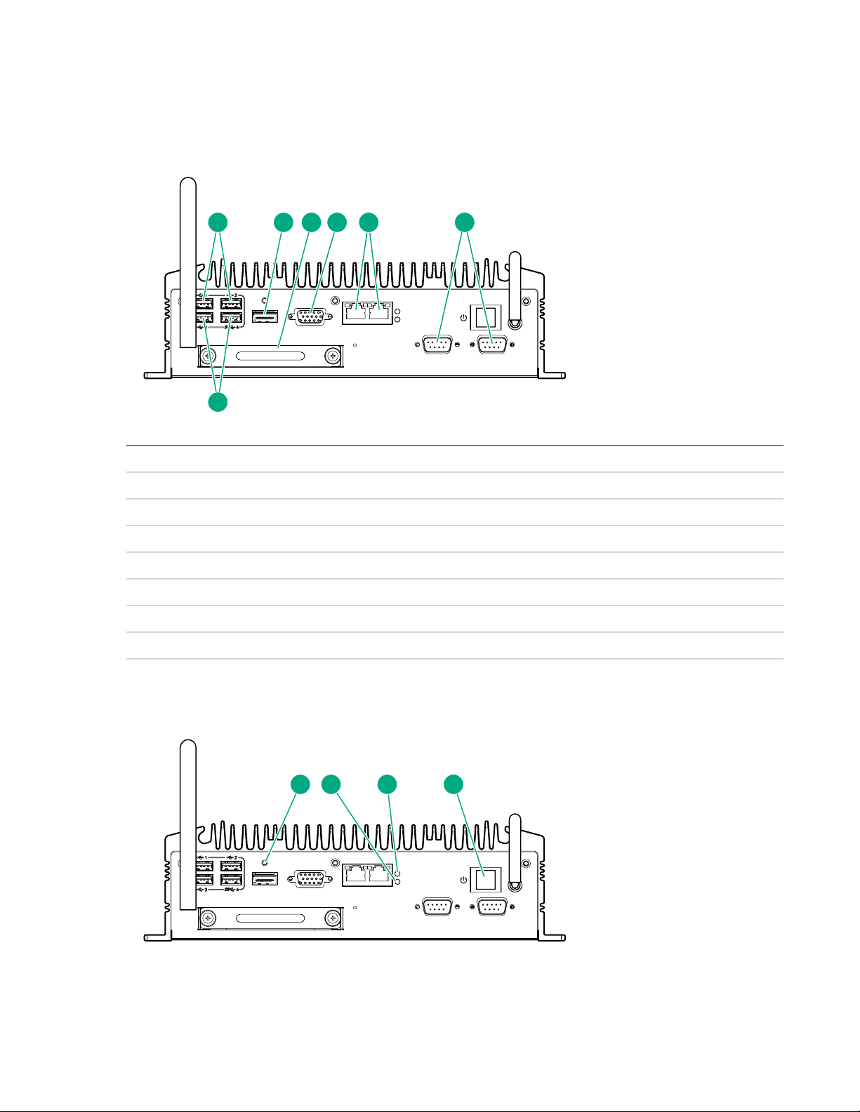
Front panel components
Item Description
1 USB 2.0 connectors (2)
2 HDMI connector
3 Drive bay
4 VGA connector
5 LAN connectors (2)
6 Optional I/O serial connectors (RS-232 or RS-422/485) (2)
7 USB 3.0 connectors (2)
Front panel LEDs and buttons
6 Component identification
Page 7
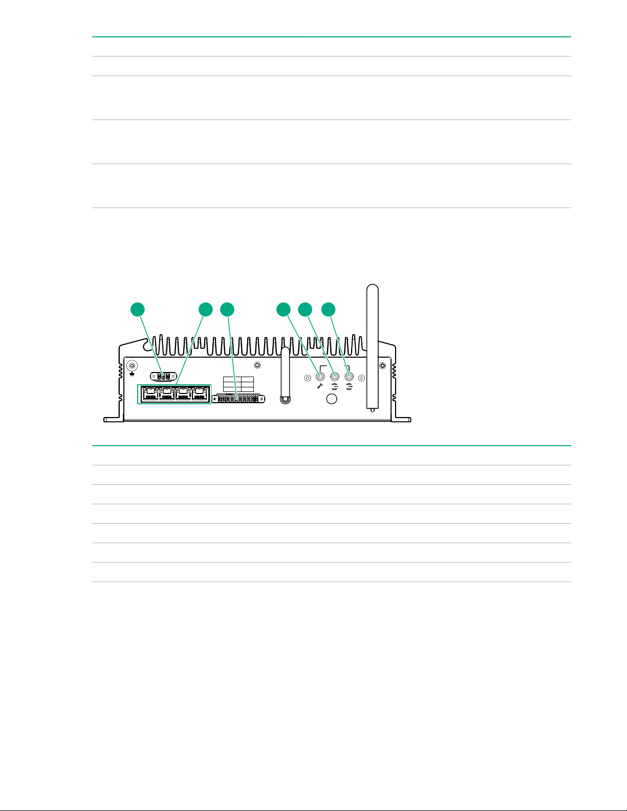
Item Description Status
PE
POE1 POE2 POE3
ANT ANT
System
ANT
POE4
PIN 0-5 DI
PIN 6-7
DO
PIN 8-9
GND
1 2 3 3 4 5 6 7 8 9
V
+V-
1 2 3 4 5 6
1 Reset button Press to reset the system
1
2 Drive LED
3 Power LED
4 Power On/Off button
1
The reset button is indented and you might need a tool such as a pin to press it.
Rear panel components
• Solid or flashing white = Drive active
• Off = Drive not active
• Solid green = System on
• Off = System off
• Solid white = System on
• Off = System off
Item Description
1 DC input connector
2 LAN connectors (10/100 Mbps) with PoE capability (4)
3 Digital I/O connector
4 Mic
5 Line in
6 Line out
Rear panel components 7
Page 8
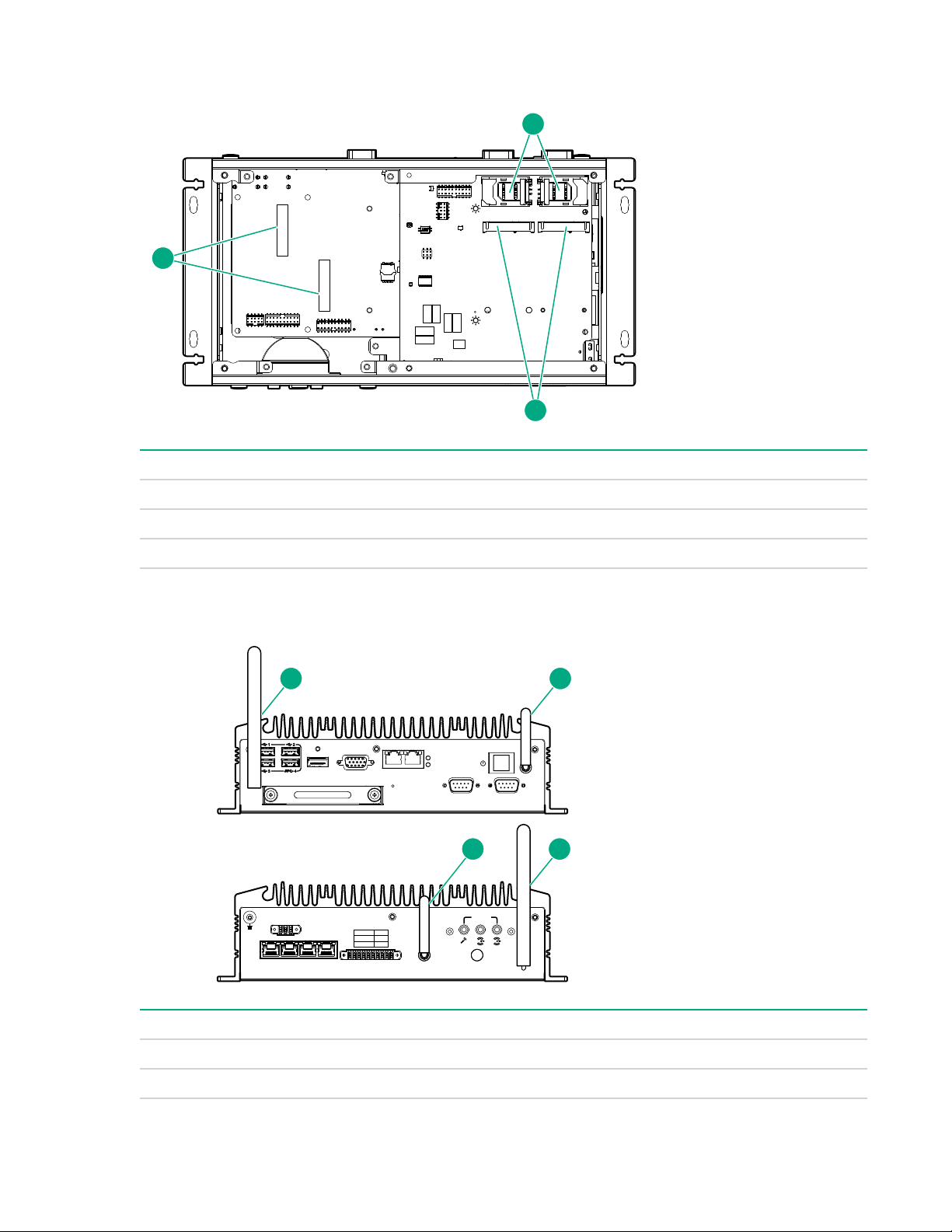
Expansion board components
2
3
1
PE
POE1 POE2 POE3
ANT ANT
System
ANT
POE4
PIN 0-5 DI
PIN 6-7
DO
PIN 8-9
GND
1 2 3 3 4 5 6 7 8 9
V
+V-
HDMI
VGA
LAN1 LAN2
PWR
Optional I/O 1 Optional I/O 2
SSD
SSD
1 2
12
Item Description
1 SIM card holders
2 3G module slots
3 WiFi/WLAN module slots
Antenna connector locations
Item Decription
1 WiFi/WLAN antenna
2 3G/LTE antenna
8 Expansion board components
Page 9

Digital I/O connector pin assignments
0 1 2 3 4 5 6 7 8 9
DI DO GND
Pin Assignment
0 to 5 Digital input
6 and 7 Digital output
8 and 9 Ground
Digital I/O connector pin assignments 9
Page 10

Operations
Install the power supply
Procedure
1. Connect the power cord to the power connector at the rear of the gateway.
2. Power up the gateway.
Power up the gateway
If the gateway is connected to a power source, it powers up automatically. It needs to be powered up only
after a manual shutdown.
To power up the gateway, press the Power On/Standby button twice.
Power down the gateway
Before powering down the gateway for any upgrade or maintenance procedures, you must back up
critical gateway data and programs.
Use one of the following methods to power down the gateway:
• Press and release the Power On/Standby button.
This method initiates a controlled shutdown of applications and the OS before the gateway enters
standby mode.
• Press and hold the Power On/Standby button for more than 4 seconds to force the gateway to power
down.
This method forces the gateway to power down without properly exiting applications and the OS. If an
application stops responding, you can use this method to force a shutdown.
Before proceeding, you must ensure that the gateway is in standby mode by verifying that the system
power LED is off.
Install the antennas
Depending on the type of antenna installed, perform one of the following procedures:
• Install the WiFi or LTE antenna on page 10
• Install the WiFi and LTE combo antennas on page 11
Install the WiFi or LTE antenna
Procedure
1. Power down the gateway on page 10.
2. Dismount the gateway on page 12.
3. Locate the correct antenna.
4. Install the antenna.
10 Operations
Page 11
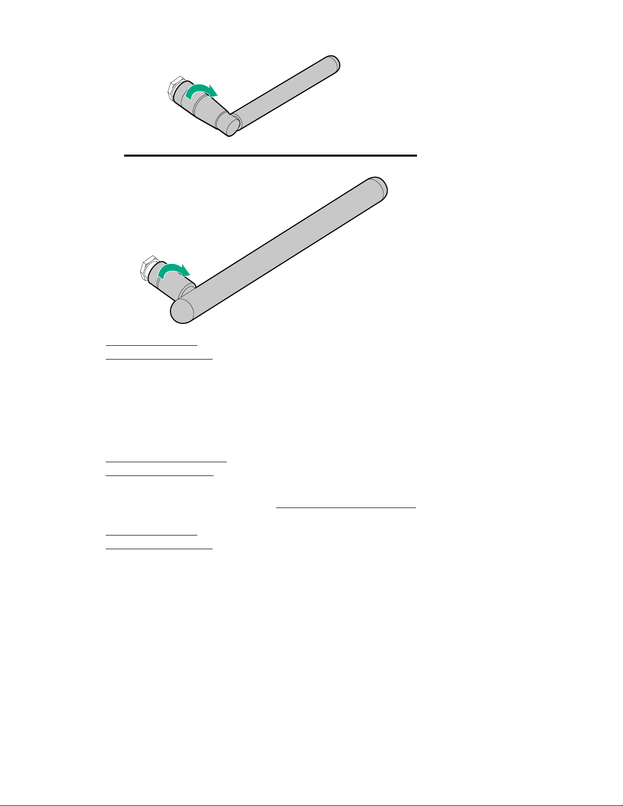
5. Mount the gateway on page 11.
6. Power up the gateway on page 10.
Install the WiFi and LTE combo antennas
You can connect WiFi antenna cables only, LTE antenna cables only, or the WiFi and LTE antenna cables
together.
Procedure
1. Power down the gateway on page 10.
2. Dismount the gateway on page 12.
3. Locate the correct port for installing the antenna cables.
For antenna connector locations, see Antenna connector locations on page 8.
4. Install the antenna cable.
5. Mount the gateway on page 11.
6. Power up the gateway on page 10.
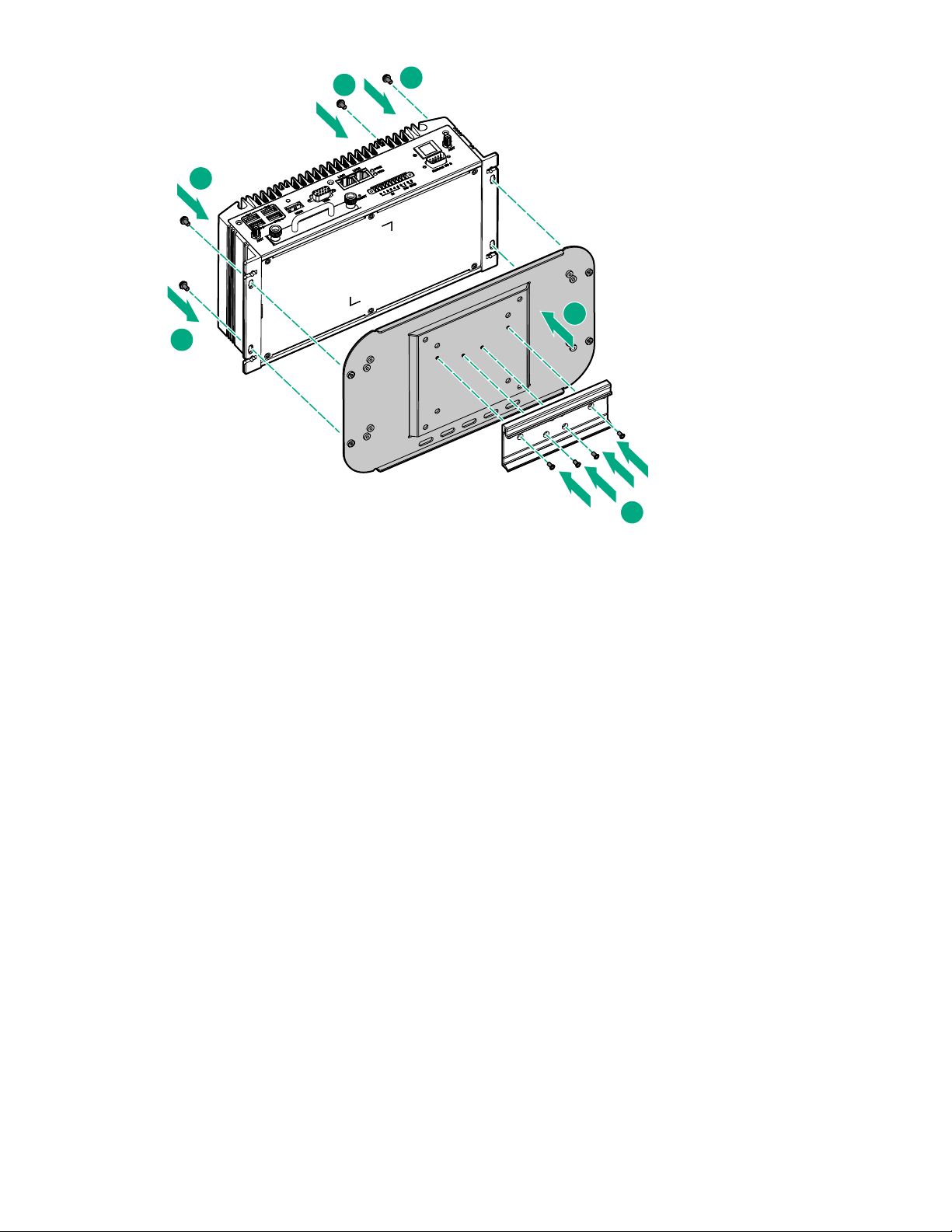
Mount the gateway
Procedure
1. Install the wall-mount bracket on the gateway with the four Torx head screws.
2. Install the wall-mount bracket to the wall with the four Torx head screws.
Install the WiFi and LTE combo antennas 11
Page 12
1
2
2
2
2
3
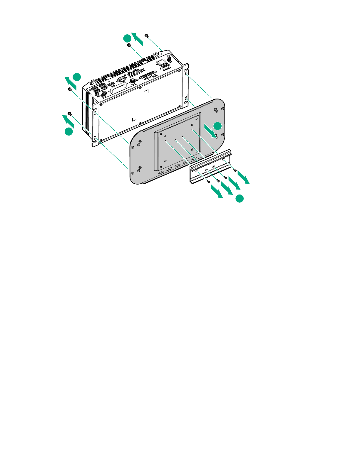
Dismount the gateway
Procedure
1. Remove the four Torx head screws securing the wall-mount bracket to the wall.
2. Remove the four Torx head screws securing the wall-mount bracket to the gateway, and then remove
the brackets.
3. Remove the wall-mount bracket from the gateway.
12 Dismount the gateway
Page 13
1
2
2
2
3
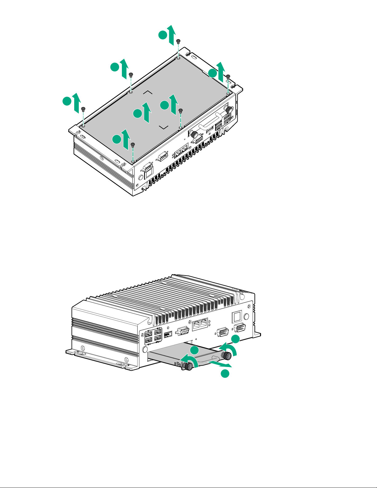
Remove the bottom access panel
Using a T-10 Torx head screwdriver, remove the six Torx head screws securing the access panel to the
bottom of the gateway.
Remove the bottom access panel 13
Page 14
1
1
1
2
1
1
1
Remove the drive tray
1
1
2
Procedure
1. Locate the drive tray on the side of the gateway.
2. Loosen the two thumbscrews securing the drive tray to the gateway, and then remove the drive tray.
14 Remove the drive tray
Page 15

Setup
IMPORTANT:
The HPE Synergy Gen10 compute module installation involves a minimum upgrade requirement for
component compatibility purposes. To ensure proper system functionality, you must update your
system to Release Set Version 3.00.20170707 (or later) before installing and operating your
compute module. Go to http://www.hpe.com/downloads/synergy and see the HPE Synergy
Firmware Update Overview guide at http://www.hpe.com/info/synergy-firmware-update-
overview-en for specific details on updating compute module components.
Optional services
Hewlett Packard Enterprise offers the HPE Foundation Care Next Business Day Exchange Service for
this product.
HPE Foundation Care Next Business Day Exchange Service provides a replacement product or part
delivered free of freight charges to your location the next business day after a call is opened and provides
support 24 hours per day, Monday through Sunday.
Hardware exchange offers a reliable and fast parts exchange service for eligible Hewlett Packard
Enterprise products. Specifically targeted at products that can easily be shipped and on which you can
easily restore data from backup files, HPE Foundation Care Next Business Day Exchange is a costefficient and convenient alternative to onsite support.
Replacement products or parts are new or equivalent to new in performance.
In addition, HPE Foundation Care Next Business Day Exchange provides electronic access to related
product and support information, enabling any member of your IT staff to locate commercially available
essential information.
For more information on HPE Foundation Care Next Business Day Exchange Service, see the
Packard Enterprise website.
Optimum environment
When installing the gateway, select a location that meets the environmental standards.
• Temperature requirements
• Power requirements
Temperature requirements
To ensure continued safe and reliable equipment operation, install or position the gateway in a wellventilated, climate-controlled environment.
Configuration Temperature
System with no modules installed Operating temperature of up to 60°C (140°F)
WiFi option without extended ambient temperature
support
Hewlett
0°C to 45°C (32°F to 113°F)
WiFi option with extended ambient temperature support -20°C to 60°C (-4°F to 140°F)
3G option -20°C to 45°C (-4°F to 113°F)
Setup 15
Page 16

Power requirements
Installation of this equipment must comply with local and regional electrical regulations governing the
installation of information technology equipment by licensed electricians. This equipment is designed to
operate in installations covered by NFPA 70, 1999 Edition (National Electric Code) and NFPA-75, 1992
(code for Protection of Electronic Computer/Data Processing Equipment). For electrical power ratings on
options, see the product rating label or the user documentation supplied with that option.
For more information on power requirements, see "Power supply specifications."
Installing hardware options
Install any hardware options before initializing the gateway. For options installation information, see the
option documentation. For gateway-specific information, see "Hardware options installation."
Installing the operating system
The HPE IoT Gateway GL20s are standard, Intel-based PC server systems. However, the gateway does
not include a CD or DVD-ROM device for installing the OS. To install a
the gateway, you can use one of the following methods:
• Installing using a USB key with an ISO image
•
Installing using local media
• Installing using PXE boot via network
supported operating system in
Installing OS using a USB key
To install an OS using a USB key, you must perform the following procedures:
• Create an ISO-imaged USB key
• Install the OS using the imaged USB key
Create an ISO-imaged USB key
Procedure
1. On a separate workstation, download the RUFUS utility.
2. Download the portable option of the RUFUS utility.
3. Run the RUFUS utility.
16 Power requirements
Page 17
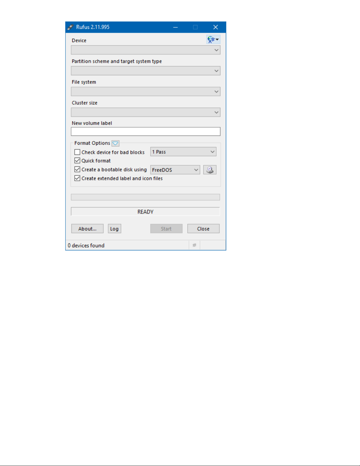
4. Insert a USB drive into the workstation.
The RUFUS utility will automatically detect the USB drive and display the drive details.
Setup 17
Page 18
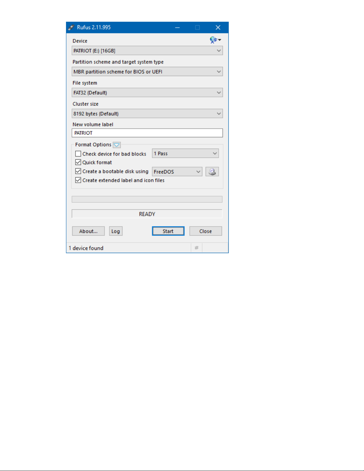
5. Select ISO image from the Create a bootable disk using drop-down.
6. Click the disk icon, and select the ISO image of the required OS.
7. Confirm that Standard Windows installation is selected.
18 Setup
Page 19

8. Click the Start button to begin the USB key imaging process.
It will take approximately 15 minutes for the imaging process to complete.
9. Click the Close button to close the RUFUS utility.
10. Safely remove the imaged USB key from the workstation.
Install OS using the imaged USB
Prerequisites
The gateway should be powered off before starting this procedure.
Procedure
1. Insert the USB key into the gateway.
2. Power up the gateway.
3. Access the System BIOS settings.
4. Navigate to the Boot tab.
For information on navigating the BIOS menu, see Navigating and modifying menu options.
5. Select Hard Drive BBS Priorities.
Install OS using the imaged USB 19
Page 20

6. Select Boot Option #1 under Boot Option Priorities.
A menu for selecting the Boot Option #1 is displayed.
7. Select the USB key as Boot Option #1.
20 Setup
Page 21

8. Press the Escape key.
9. Navigate to the Save & Exit tab.
10. Select Boot Override.
11. Select the USB key option.
Setup 21
Page 22

12. Press Enter.
13. Follow the OS installation prompts to complete the OS installation on the device.
Wait for the OS installation to complete.
14. Remove the USB key from the gateway.
The OS installation from the USB key is complete. The gateway boots from the new HDD at reboot.
Installing OS using local media
You can use local media such as a USB CD, DVD, or disk drive with installation media to install the OS.
To install the OS, access the System BIOS settings.
The last BIOS screen will enable you to select your installation media, temporarily overriding the default
boot order.
Registering the product
To experience quicker service and more efficient support, register the product at the Hewlett Packard
Enterprise Product Registration website.
22 Installing OS using local media
Page 23

Hardware options installation
WAN
WAN
Installing the 3G/LTE module
Procedure
1. Power down the gateway on page 10.
2. Dismount the gateway on page 12.
CAUTION:
DO NOT remove the top access panel under any circumstance. Removing the top access panel
can harm the heatsink or void the warranty to the equipment.
3. Remove the bottom access panel on page 13.
NOTE:
The 3G/LTE module can be installed in either of the two PCI slots. If there is only one 3G/LTE
module installed, Hewlett Packard Enterprise recommends installing in the slot on the right.
NOTE:
If you are installing a module that requires USB routing, install the module in the full-height PCIe
slot. The half-height PCIe slot on the system board does not support USB signal.
4. Using a T-10 Torx screwdriver, install the module with the two screws.
5. Connect the two WAN antenna cables to the antenna connectors on the 3G/LTE module.
Hardware options installation 23
Page 24

WAN
WAN
6. Install the bottom access panel.
7. Mount the gateway on page 11.
8. Power up the gateway on page 10.
Installing the half-length WiFi/WLAN module
You will need a half-length WiFi module adapter provided with the WiFi option kit to install this option.
Procedure
1. Power down the gateway on page 10.
2. Dismount the gateway on page 12.
CAUTION:
DO NOT remove the top access panel under any circumstance. Removing the top access
panel can harm the heatsink or void the warranty to the equipment.
3. Remove the bottom access panel on page 13.
4. Remove the drive tray on page 14.
5. Install the WiFi module adapter using the two holes of the half-length WiFi module.
24 Installing the half-length WiFi/WLAN module
Page 25

1
1
2
6. Insert the WiFi module connector into the full-length WiFi module slot.
WLAN
WLAN
7. Using a T-10 Torx screwdriver, install the half-length WiFi module and adapter assembly with the two
screws.
8. Connect the two WLAN antenna cables to the antenna connectors on the half-length WiFi module.
Hardware options installation 25
Page 26

WiFi
WiFi
9. Install the bottom access panel.
WLAN
WLAN
10. Mount the gateway on page 11.
11. Power up the gateway on page 10.
Installing the full-length WiFi/WLAN module
Procedure
1. Power down the gateway on page 10.
2. Dismount the gateway on page 12.
CAUTION:
DO NOT remove the top access panel under any circumstance. Removing the top access panel
can harm the heatsink or void the warranty to the equipment.
3. Remove the bottom access panel on page 13.
4. Remove the drive tray on page 14.
5. Using a T-10 Torx screwdriver, install the full-length WiFi module with the two screws.
26 Installing the full-length WiFi/WLAN module
Page 27

6. Connect the two WLAN antenna cables to the antenna connectors on the full-length WiFi module.
WLAN
WLAN
7. Install the bottom access panel.
8. Mount the gateway on page 11.
9. Power up the gateway on page 10.
Hardware options installation 27
Page 28

Software and configuration utilities
Product QuickSpecs
For more information about product features, specifications, options, configurations, and compatibility, see
the product QuickSpecs on the Hewlett Packard Enterprise website (
Supported operating systems and drivers matrix
Operating system support
For more information on Hewlett Packard Enterprise Certified and Supported systems for the operating
systems available for your system, see the Hewlett Packard Enterprise OS support website:
http://www.hpe.com/info/ossupport
ROM, BIOS, and driver support
For more information on Hewlett Packard Enterprise Certified and Supported systems for the latest
software ROM, BIOS, and drivers available for your system, see the Hewlett Packard Enterprise Support
Center website:
http://www.hpe.com/support/hpesc
http://www.hpe.com/info/qs).
System BIOS
Updating the system BIOS
You can download the latest system BIOS, whenever updates are available, from the Hewlett Packard
Enterprise Support Center website (http://www.hpe.com/info/ossupport).
For more information on product entitlement, and accessing product updates, see Accessing updates
on page 54.
Prerequisites
• You need an empty USB drive that is FAT32 formatted for saving the utility and bin files for updating
the system BIOS.
• Product entitlement is required to perform updates.
Procedure
1. Go to the Hewlett Packard Enterprise Support Center website.
2. Download the afuefix64.efi utility and <xxxxx> BIOS bin files to the USB drive.
3. Remove the USB drive and connect it to the system.
4. Power up the gateway on page 10.
5. Access the system BIOS (Accessing the system BIOS on page 35).
6. Locate the BIOS version.
If the Build Date is 12/16/2015, the BIOS must be updated.
28 Software and configuration utilities
Page 29

7. Identify the current Management Engine version by using Advanced —> PCH-FW Configuration.
The old Management Engine Firmware version is 9.5.13.1706 and the updated version is
9.5.61.3012.
Software and configuration utilities 29
Page 30

Alternatively, press the Ctrl+P keys while the device boots to identify the ME FW version.
8. Modify the following settings in the BIOS:
a. Set ME FW Image Re-Flash to [Enabled] by using Advanced—>PCH-FW Configuration—
>Firmware Update Configuration.
b. Set UEFI: Built-in EFI Shell as Boot Option #1.
30 Software and configuration utilities
Page 31

9. Select Save Changes and Exit.
The settings changes made so far will take effect only if you save and exit.
The system will now boot to the Shell. The following is a sample screen:
If your screen looks different from the sample screen provided, reset the UEFI: Built-in EFI Shell to
Boot Option #1.
10. Identify the USB drive.
Software and configuration utilities 31
Page 32

The following is a sample screen with fs1 as the USB drive.
11. Initiate the BIOS update:
a. To select the USB drive, enter the fs1: command.
b. To ensure that both the utility and bin files are visible, enter the dir command.
c. To initiate the update, enter the AfuEfix64.efi XXXX.bin /P /B /N /X /ME command.
In the following sample screen, the command is: AfuEfix64.efi
L510K112.BIN /P /B /N /X /ME
You will see a screen similar to the following while the update is in progress:
32 Software and configuration utilities
Page 33

After the update, one of the following screens appear:
• An error screen showing that the BIOS does not support ME Entire Firmware update. The
following is a sample screen:
Software and configuration utilities 33
Page 34

To fix this error, repeat the steps from accessing the BIOS to save changes and exit, and then
run the update again.
• A screen showing that the BIOS update was successful. The following is a sample screen:
12. Power down the gateway on page 10 for the changes to take effect.
All BIOS options are restored to the default values and the Management Engine password is set back to
the default password.
The Build Date now appears updated to 06/13/2017 on the BIOS Main tab. The ME FW version is now
9.5.61.3012.
Using the system BIOS to configure gateway and troubleshoot issues
The gateway can be set up and configured through the system BIOS. The system BIOS also has options
for restoring default configurations and resetting the system. The setup information is stored in the
battery-backed CMOS, therefore it retains the setup information even when the power is turned off.
34 Using the system BIOS to configure gateway and troubleshoot issues
Page 35

For more information, see "Setting up the system BIOS."
Accessing the system BIOS
Procedure
1. Connect KVM to the gateway.
2. Power up the gateway.
3. Press the Delete key or the F2 key.
The BIOS Main tab is displayed.
Setting up the system BIOS
BIOS menu components
The BIOS menu has the following frames:
• Left frame—Displays the sub menu. Only the sub-menu options in blue can be modified. When an
option is selected in the left frame, it is highlighted in white.
• Top right frame—Displays information about the sub-menu option selected.
• Bottom right frame—Displays the keys to use to make changes to the selected sub menu.
Navigating and modifying menu options
Procedure
1. Access the system BIOS.
2. Press the right arrow key to navigate to the tab to modify.
3. Press the up and down arrow keys to navigate to the sub-menu options on the left frame.
4. When you reach a sub-menu option to modify, press the Enter key.
5. Press the + key or the - key to modify the setting selected.
6. Do one of the following:
• Press the F4 key to save the new setting and exit.
• Press the Esc key to exit without saving.
Accessing the system BIOS 35
Page 36

Main tab
Setting the System Date and System Time
Procedure
1. Access the system BIOS Main tab.
2. Press the up and down arrow keys to navigate to the sub-menu options on the left frame.
3. When you reach a sub-menu option to modify, press the Enter key.
4. Press the Tab key or the arrow keys to navigate the fields.
5. Enter the new values.
The date must be entered in the MM/DD/YY format. The time must be entered in the HH:MM:SS
format.
6. Do one of the following:
• Press the F4 key to save the new values and exit.
• Press the Esc key to exit without saving.
Advanced tab
The Advanced tab has the following menu options:
• PCI Subsystem Settings
• ACPI Settings
• S5 RTC Wake Settings
• CPU Configuration
• SATA Configuration
36 Main tab
Page 37

• Intel(R) Rapid Start Technology
• PCH-FW Configuration
• AMT Configuration (not active)
• USB Configuration
• Embedded Controller Configuration
• IT8768 Super IO Configuration
• Serial Port Console Redirection
• Network Stack
• Intel(R) Ethernet Connection
PCI Subsystem Settings
The PCI Bus driver version and common settings are displayed, including:
• PCI Latency Timer—Displays value programmed into the PCI Latency Timer Registry
• VGA Palette Snoop—Enables or disables VGA palette register snooping
• PERR# Generation—Enables or disables the PCI device to generate PERR#
• SERR# Generation—Enables or disables the PCI device to generate SERR#
• PCI Express Settings:
◦ Relaxed Ordering—Enables or disables PCI Express device relaxed ordering
◦ Extended Tag—Enables user to set the PCI Express device to use an 8-bit tag field as a requester
◦ No Snoop—Enables or disables PCI Express device No Snoop option
◦ Maximum Payload—Enables user to set maximum payload of PCI Express device, or allow the
system BIOS to select the value (Auto)
◦ Maximum Read Request—Enables user to set maximum read request size of PCI Express device
or allow the system BIOS to select the value (Auto)
◦ ASPM Support—Enables user to set the ASPM level
PCI Subsystem Settings 37
Page 38

◦ Extended Synch—Enables user to allow the generation of extended synchronization patterns.
◦ Link Training Retry—Enables user to define the number of retry attempts the software will make
to retrain the link if previous training attempt was unsuccessful
◦ Link Training Timeout (uS)—Enables user to define the number of microseconds the software will
wait before polling 'Link Training' bit in Link Status register. Values range from 10 to 10,000.
◦ Unpopulated Links—Enables user to set to 'Disable Link' in order to save power by unpopulating
the PCI Express links
◦ Restore PCIE Registers—Enables user to restore PCI Express device configurations. Enabling
might cause issues with other hardware components.
ACPI Settings
• Enable ACPI Auto Configuration—Enables or disables BIOS ACPI auto configuration
• Enable Hibernation—Enables or disables the system's ability to hibernate
• ACPI Sleep State—Enables user to set the ACPI sleep state
• Lock Legacy Resources—Enables or disables the lock of legacy devices' resources
• S3 Video Repost—Enables or disables S3 video repost
• ACPI Low Power S0 Idle—Enables or disables system wake on alarm event by items settings
S5 RTC Wake Settings
Wake system with fixed time—Enables or disables system wake on alarm event
CPU Configuration
General CPU configuration values and settings are displayed, including:
• Hyper Threading—Enables or disables Intel Hyper Threading technology
• Active Processor Cores—Enables user to set the number of processor cores that should be active
• Limit CPUID Maximum—Enables user to limit the maximum value of CPUID
• Execute Disable Bit—Enables or disables the No-Execution page protection technology
• Intel Virtualization Technology—Enables or disables Intel’s virtualization technology
• Hardware Prefetcher—Enables or disables the hardware pre-fetcher feature
• Adjacent Cache Line Prefetch—Enables or disables the adjacent cache line pre-fetch feature
• CPU AES—Enables or disables CPU Advanced Encryption Standard instructions
• Boot performance mode—Enables user to select the performance state that the BIOS will set before
OS handoff
• EIST—Enables or disables Intel SpeedStep
• Turbo Mode—Enables or disables Turbo mode
• Energy Performance—Enables user to optimize performance and power savings
• CPU C-states—Enables or disables CPU C-states
• ACPI CTDP BIOS—Enables or disables the ACPI CTDP BIOS support
• Configurable TDP Level—Enables user to allow reconfiguration of TDP levels based on current
power and thermal delivery capabilities of the system
• Config TDP LOCK—Enables user to lock the Config TDP Control register
SATA Configuration
• SATA Controller(s)—Enables or disables the SATA controllers
• SATA Mode Selection—Enables user to select the mode of SATA controllers
• Aggressive LPM Support—Enables or disables the aggressive LPM support
• SATA Controller Speed—Enables user to select the mode of SATA controller speed
• Software Feature Mask Configuration—Enables or disables storage features
Each SATA port is displayed with the following information and options:
38 ACPI Settings
Page 39

• Software Preserve
• Port #—Enables or disables the SATA port
• Hot Plug—Enables or disables the hot plug
• External SATA—Enables or disables the external SATA
• SATA Device type—Enables user to select the mode of SATA device type
Intel(R) Rapid Start Technology
Intel(R) Rapid Start Technology—Enables or disables Rapid Start Technology, if supported
PCH-FW Configuration
The ME technology parameters are displayed, including:
• ME Firmware Version—Displays the current firmware version
• ME Firmware Mode—Displays the current firmware mode
• ME Firmware Type—Displays the current firmware type
• ME Firmware SKU—Displays the current firmware SKU
• PTT Capability/State—Displays the PTT capability and state
• Firmware Update Configuration—Enables or disables ME firmware image re-flash function
USB Configuration
The USB configuration and device options are displayed, including:
• Legacy USB Support—Enables user to set support for legacy USB. Auto option disables legacy
support if no USB devices are connected.
• USB 3.0 Support—Enables or disables USB 3.0 support
• XHCI Hand-Off—Offers user a workaround for the OS without XHCI hand-off support. The XHCI
ownership change should be claimed by the XHCI driver.
• EHCI Hand-Off—Offers user a workaround for the OS without EHCI hand-off support. The EHCI
ownership change should be claimed by the EHCI driver.
• USB Mass Storage Driver Support—Enables or disables mass storage support
• USB transfer time-out—Enables user to set the time-out value for control, bulk, and interrupt
transfers
• Device reset time-out—Enables user to set the USB mass storage device start unit command timeout value
• Device power-up delay—Enables user to set the maximum time the device will take before it properly
reports itself to the Host Controller. 'Auto' uses default value: for a Root port it is 100 ms: for a Hub
port the delay is taken from Hub descriptor.
Embedded Controller Configuration
The EC firmware version and general functions are displayed, including:
• EC Power Saving Mode—Enables user to set the EC power saving mode
• EC Watchdog Function—Enables user to set the EC watchdog timer
IT8768 Super IO Configuration
The Super Chip configuration details are displayed, including:
• Serial Port 1 Configuration—Enables user to configure serial port 1
• Serial Port 2 Configuration—Enables user to configure serial port 2
Serial Port Console Redirection
The COM1 settings and console redirection settings are displayed, including:
Intel(R) Rapid Start Technology 39
Page 40

• Console Redirection—Enables or disables console redirection for Microsoft Windows EMS
• Console Redirection Settings—Enables user to set configuration console redirection detail settings
Network Stack
Network Stack—Enables or disables the UEFI network stack
Intel (R) Ethernet Connection
The Port Configuration Menu information is displayed, including:
• NIC Configuration—Enables user to configure the boot protocol, wake on LAN, link speed, and VLAN
details
• Blink LEDs—Enables user to identify the physical network port by flashing the associated LED
• Link Status—Displays the link status (connected or disconnected)
Chipset tab
The Chipset tab has the following sub-menu options:
• PCH-IO Configuration
• System Agent (SA) Configuration
PCH-IO Configuration
• PCI Express Configuration—Displays PCIE1~PCIE8 root port detail configuration settings:
◦ PCI Express Clock Gating—Enables or disables PCI Express Clock Gating for each root port
◦ DMI Link ASPM Control—Enables or disables the DMI Link ASPM Control
◦ DMI Link Extended Synch Control—Enables user to configure the Mini PCI Express setting
40 Network Stack
Page 41

◦ PCIe-USB Glitch W/A—Enables or disables PCIe-USB Glitch workaround for bad USB devices
connected behind the PCIE/PEG Port.
◦ PCI Root Port Function Swapping—Enables or disables PCI Express root port function swapping
◦ Subtractive Decode—Enables or disables subtractive decode
◦ PCI Express Root Port 1/2/3/6—Enables user to configure PCI express root port 1/2/3/6 setting
• USB Configuration—Displays configuration of USB functions:
◦ USB Precondition—Enables or disables USB precondition. Precondition work on the USB host
controller and root ports for faster enumeration.
◦ XHCI Mode—Enables user to select the mode of operation of XHCI mode
◦ XHCI Idle L1—Enables or disables XHCI Idle L1. The XHCIIDLE L1 can be set to disabled for LPT-
LP Ax stepping to work around USB 3. 0 hot plug failure after 1 hot-plug removal.
◦ BTCG—Enables or disables trunk clock gating
◦ USB Ports Per-Port Disable Control—Enables or disables USB ports per-port disable control
• PCH Azalia Configuration—Displays configuration of azalia functions
• LAN 1/2 controller—Enables or disables the LAN 1/2 controller:
◦ LAN 1/2 PXE Rom—Enables or disables PXE Rom for LAN 1/2
◦ Wake on LAN—Enables or disables LAN1 wake up from sleep state
• PCIE Wake from S5—Enables or disables PCIE device wake up from S5
• USB Wake From S4 Support—Enables or disables USB to wake the system from S4
• SLP_S4 Assertion Width—Enables user to set a delay
• Restore AC Power Loss—Enables user to set off, on, and last state
System Agent (SA) Configuration
• VT-d—Enables or disables VT-d
• Graphics Configuration:
◦ Graphics Turbo IMON Current—Enables user to select the graphics turbo IMON current
◦ Primary Display—Enables user to select primary display
◦ Internal Graphics—Enables or disables IGD
◦ Aperture Size—Enables user to select aperture size
◦ DVMT Pre-Allocated—Enables user to select DVMT pre-allocated memory size
◦ DVMT Total Gfx Mem—Enables user to select DVMT total memory size
◦ Gfx Lower Power Mode—Available for SFF only. Enables user to lower the graphics power mode.
◦ LCD Control:
Primary IGFX Boot Display—Enables user to select boot display device at post stage
• Memory Configuration:
Memory Information—Displays memory configuration parameters
Boot tab
The Boot tab has the following sub-menu options:
• Setup Prompt Timeout—Displays the number of seconds to wait for setup activation key
• Bootup NumLock State—Enables to select the keyboard NumLock state
• Quiet Boot—Enables or disables the Quiet Boot option
• UEFI Boot—Enables or disables the ability to boot from UEFI devices
• Boot Option Priorities—Enables user to set the system boot priority order
• Hard Drive BBS Priorities—Enables user to set the order of legacy devices
• CSM parameters —Enables user to set the order of legacy devices
System Agent (SA) Configuration 41
Page 42

CSM parameters
• Launch CSM—Enables or disables CSM launch
• Boot option filter—Enables user to select which devices the system can boot to
• Launch PXE OpROM policy—Enables user to control the execution of UEFI and legacy PXE Option
ROM
• Launch Storage OpROM policy—Enables user to control the execution of UEFI and legacy Storage
Option ROM
• Launch Video OpROM policy—Enables user to control the execution of UEFI and legacy Video
Option ROM
• Other PCI device ROM priority—Enables user to define which Option ROM to launch for PCI devices
other than network, mass storage, or video
Security tab
The Security tab has the following sub-menu options:
• Administrator password—Enables user to set the administrator password
• User password—Enables user to set the user password
• HDD Security configuration—Enables user to set the HDD password
• Secure Boot menu —Enables user to customize the secure boot settings
42 CSM parameters
Page 43

Secure Boot
The system mode and secure boot configuration is displayed, including the following:
• Secure Boot—Enables or disables Secure Boot
• Secure Boot Mode—Secure Boot mode selector. Enables user to change the image execution policy
and manage secure boot keys
• Key Management—Enables experienced users to modify secure boot variables:
◦ Default Key Provision—Enables user to install factory default secure boot keys when the system
is in Setup mode
◦ Enroll All Factory Default Keys—Enables user to force system into User mode after reboot
◦ Save All Secure Boot Variables—Enables user to store the content of each secure boot variable
to file system root folder
◦ Platform Key—Enables user to delete or set new Platform Key
◦ Key Exchange Key—Enables user to delete, set, or append Key Exchange Key
◦ Authorized Signatures—Enables user to delete, set, or append DB
◦ Authorized Timestamps—Enables user to delete, set, or append DBT
◦ Forbidden Signatures—Enables user to delete, set, or append DBX
Save & Exit tab
The Save & Exit menu tab includes the following menu options:
• Save Changes and Exit—Enables user to exit system setup after saving changes
• Discard Changes and Exit—Enables user to exit system setup without saving any changes
• Save Changes and Reset—Enables user to reset the system after saving the changes
• Discard Changes and Reset—Enables user to reset the system without saving the changes
• Save Changes—Enables user to save changes made so far to any of the options
Secure Boot 43
Page 44

• Discard Changes—Enables user to discard changes made so far to any of the options
• Restore Defaults—Enables user to restore/load default values for all the options
• Save as User Defaults—Enables user to save the changes made so far as user defaults
• Restore User Defaults—Enables user to restore the user defaults to all the options
• Boot Override—Enables user to override your boot priority
44 Software and configuration utilities
Page 45

Troubleshooting
Troubleshooting resources
The HPE IoT Gateway GL20 (Formerly HPE EL20 Intelligent Gateway) Maintenance and Service Guide
includes additional troubleshooting resources, and is available on the Hewlett Packard Enterprise website
http://www.hpe.com/info/edgeline-docs).
(
Troubleshooting 45
Page 46

Battery
Battery specifications
Feature Specification
Type CR2032 RTC batteries with a rating of 210 mAh
Power Battery RTC circuitry draws 2uA when in use (system off)
Maximum Battery
Life Cycle
Maximum Battery
Life Cycle under
Storage Mode
Maximum Battery
Life Cycle under
Operation Mode
210 mAh/2 uAh = 10,5000 hours
105000 hours/(365 x 24) = 11.98 years
(Battery in Storage Mode - System Powered Off all day, RTC battery is in use)
105000 hours/(365 x (24-8)) = 17.97 years
(Battery in Operation Mode - System Power On, 8 hours/day, RTC circuitry does
not use battery power when system is on)
46 Battery
Page 47

Warranty and regulatory information
Warranty information
To view the warranty for your product or to view the Safety and Compliance Information for Server,
Storage, Power, Networking, and Rack Products reference document, go to the Enterprise Safety and
Compliance website:
www.hpe.com/support/Safety-Compliance-EnterpriseProducts
Additional warranty information
HPE ProLiant and x86 Servers and Options
www.hpe.com/support/ProLiantServers-Warranties
HPE Enterprise Servers
www.hpe.com/support/EnterpriseServers-Warranties
HPE Storage Products
www.hpe.com/support/Storage-Warranties
HPE Networking Products
www.hpe.com/support/Networking-Warranties
Regulatory information
To view the regulatory information for your product, view the Safety and Compliance Information for
Server, Storage, Power, Networking, and Rack Products, available at the Hewlett Packard Enterprise
Support Center:
www.hpe.com/support/Safety-Compliance-EnterpriseProducts
Additional regulatory information
Hewlett Packard Enterprise is committed to providing our customers with information about the chemical
substances in our products as needed to comply with legal requirements such as REACH (Regulation EC
No 1907/2006 of the European Parliament and the Council). A chemical information report for this product
can be found at:
www.hpe.com/info/reach
For Hewlett Packard Enterprise product environmental and safety information and compliance data,
including RoHS and REACH, see:
www.hpe.com/info/ecodata
For Hewlett Packard Enterprise environmental information, including company programs, product
recycling, and energy efficiency, see:
www.hpe.com/info/environment
Belarus Kazakhstan Russia marking
Manufacturer and Local Representative Information
Warranty and regulatory information 47
Page 48

Manufacturer information:
• Hewlett Packard Enterprise Company, 3000 Hanover Street, Palo Alto, CA 94304 U.S.
Local representative information Russian:
• Russia:
• Belarus:
• Kazakhstan:
Local representative information Kazakh:
• Russia:
• Belarus:
• Kazakhstan:
Manufacturing date:
The manufacturing date is defined by the serial number.
CCSYWWZZZZ (serial number format for this product)
Valid date formats include:
• YWW, where Y indicates the year counting from within each new decade, with 2000 as the starting
point; for example, 238: 2 for 2002 and 38 for the week of September 9. In addition, 2010 is indicated
by 0, 2011 by 1, 2012 by 2, 2013 by 3, and so forth.
• YYWW, where YY indicates the year, using a base year of 2000; for example, 0238: 02 for 2002 and
38 for the week of September 9.
Turkey RoHS material content declaration
48 Turkey RoHS material content declaration
Page 49

Ukraine RoHS material content declaration
Japanese certification mark for 3G module
Federal Communications Commission notice for Class A equipment
This device complies with part 15 of the FCC Rules. Operation is subject to the following conditions:
• This device may not cause harmful interference.
• This device must accept any interference received, including interference that may cause undesired
operation.
This equipment has been tested and found to comply with the limits for a Class A digital device, pursuant
to part 15 of the FCC Rules. These limits are designed to provide reasonable protection against harmful
interference when the equipment is operated in a commercial environment. This equipment generates,
uses, and can radiate radio frequency energy and, if not installed and used in accordance with the
instruction manual, may cause harmful interference to radio communications. Operation of this equipment
in a residential area is likely to cause harmful interference in which case the user will be required to
correct the interference at their own expense.
This equipment complies with radio frequency (RF) exposure limits adopted by the Federal
Communications Commission for an uncontrolled environment. This equipment should be installed and
operated with a minimum distance of 20 cm between the radiator and your body.
Changes or modifications not expressly approved by the party responsible for compliance could void the
authority of the user to operate the equipment.
European Union (CE) compliance
Operating frequency band Maximum radio frequency (RF) power
transmitted (dBm)
2.4 GHz 18
5 GHz 8.5
GSM 900 33
The device is restricted to indoor use only when operating in the 5150 to 5350 MHz frequency range.
AT BE BG HR CY CZ DK
EE FI FR DE EL HU IE
IT LV LT LU MT NL PL
PT RO SK SI ES SE UK
Ukraine RoHS material content declaration 49
Page 50

WARNING:
Risk of explosion if a battery is replaced by an incorrect type. Dispose of used batteries according to
the instructions.
RF exposure information
This device has been tested and meets applicable limits for Radio Frequency (RF) exposure. Specific
Absorption Rate (SAR) refers to the rate at which the body absorbs RF energy. Tests for SAR are
conducted using standard operating positions with the device transmitting at its highest certified power
level in all tested frequency bands. This device was tested with a separation distance of 25 mm. Always
keep this device away from your body to ensure exposure levels remain at or below the as-tested levels.
Hereby, Hewlett Packard Enterprise declares that the radio equipment type used in the gateway is in
compliance with Directive 2014/53/EU. The full text of the EU declaration of conformity is available at the
following internet address:
www.address.com/DoC.pdf
The European Union WEEE Directive Page is available at: http://h20564.www2.hpe.com/portal/site/
hpesc/public/kb/docDisplay/?docId=c03471072.
50 Warranty and regulatory information
Page 51

Specifications
Product QuickSpecs
For more information about product features, specifications, options, configurations, and compatibility, see
the product QuickSpecs on the Hewlett Packard Enterprise website (
Environmental specifications
Specification Value
Temperature range
1
http://www.hpe.com/info/qs).
—
Operating
Non-operating -40°C to 85°C (-40°F to 185°F)
Relative humidity (noncondensing) 95% relative humidity at 40°C
1
All temperature ratings shown are for sea level. An altitude derating of 1.0°C per 304.8 m (1.8°F per 1000 ft) to 3048
m (10,000 ft) is applicable. No direct sunlight allowed. Maximum rate of change is 20°C per hour (36°F per hour).
Mechanical specifications
Specification Value
Length 26.45 cm (10.41 in)
Width 13.30 cm (5.24 in)
Depth 7.51 cm (2.96 in)
Weight 2.72 kg (6.0 lb)
Power supply specifications
-20°C to 60°C (-4°F to 140°F) with 0.7 m/s air flow
with extended temperature peripherals
0°C to 45°C (32°F to 113°F) with 0.7 m/s air flow
with extended temperature peripherals
Specification Value
AC input to power supply requirements
Rated input voltage 100 to 240 VAC
Rated input frequency 50 Hz to 60 Hz
Rated input current 2.0 A
DC direct input requirements
Rated input voltage 9 to 36 VDC (1.5 KV isolated)
Rated input frequency >10.9V for full power
Table Continued
Specifications 51
Page 52

Rated input current ~12.5 A (@ 12 VDC)
Power supply output
Rated output voltage 19.0 V
Rated output current 7.89 A
Power consumption specifications
Specification Value
Typical 70 W with full load on PoE
Maximum 35 W
1
The four-port PoE power budget is 30 W in total. Each PoE port supports up to <15 W at 802.3af Class 3.
1
52 Power consumption specifications
Page 53

Websites
General websites
Hewlett Packard Enterprise Information Library
www.hpe.com/info/EIL
Single Point of Connectivity Knowledge (SPOCK) Storage compatibility matrix
www.hpe.com/storage/spock
Storage white papers and analyst reports
www.hpe.com/storage/whitepapers
For additional websites, see Support and other resources.
Websites 53
Page 54

Support and other resources
Accessing Hewlett Packard Enterprise Support
• For live assistance, go to the Contact Hewlett Packard Enterprise Worldwide website:
http://www.hpe.com/assistance
• To access documentation and support services, go to the Hewlett Packard Enterprise Support Center
website:
http://www.hpe.com/support/hpesc
Information to collect
• Technical support registration number (if applicable)
• Product name, model or version, and serial number
• Operating system name and version
• Firmware version
• Error messages
• Product-specific reports and logs
• Add-on products or components
• Third-party products or components
Accessing updates
• Some software products provide a mechanism for accessing software updates through the product
interface. Review your product documentation to identify the recommended software update method.
• To download product updates:
Hewlett Packard Enterprise Support Center
www.hpe.com/support/hpesc
Hewlett Packard Enterprise Support Center: Software downloads
www.hpe.com/support/downloads
Software Depot
www.hpe.com/support/softwaredepot
• To subscribe to eNewsletters and alerts:
www.hpe.com/support/e-updates
• To view and update your entitlements, and to link your contracts and warranties with your profile, go to
the Hewlett Packard Enterprise Support Center More Information on Access to Support Materials
page:
www.hpe.com/support/AccessToSupportMaterials
IMPORTANT:
Access to some updates might require product entitlement when accessed through the Hewlett
Packard Enterprise Support Center. You must have an HPE Passport set up with relevant
entitlements.
54 Support and other resources
Page 55

Customer self repair
Hewlett Packard Enterprise customer self repair (CSR) programs allow you to repair your product. If a
CSR part needs to be replaced, it will be shipped directly to you so that you can install it at your
convenience. Some parts do not qualify for CSR. Your Hewlett Packard Enterprise authorized service
provider will determine whether a repair can be accomplished by CSR.
For more information about CSR, contact your local service provider or go to the CSR website:
http://www.hpe.com/support/selfrepair
Remote support
Remote support is available with supported devices as part of your warranty or contractual support
agreement. It provides intelligent event diagnosis, and automatic, secure submission of hardware event
notifications to Hewlett Packard Enterprise, which will initiate a fast and accurate resolution based on your
product's service level. Hewlett Packard Enterprise strongly recommends that you register your device for
remote support.
If your product includes additional remote support details, use search to locate that information.
Remote support and Proactive Care information
HPE Get Connected
www.hpe.com/services/getconnected
HPE Proactive Care services
www.hpe.com/services/proactivecare
HPE Proactive Care service: Supported products list
www.hpe.com/services/proactivecaresupportedproducts
HPE Proactive Care advanced service: Supported products list
www.hpe.com/services/proactivecareadvancedsupportedproducts
Proactive Care customer information
Proactive Care central
www.hpe.com/services/proactivecarecentral
Proactive Care service activation
www.hpe.com/services/proactivecarecentralgetstarted
Customer self repair 55
Page 56

Acronyms and abbreviations
ACPI
Advanced Configuration and Power Interface
AES
Advanced Encryption Standard
AMT
Active Management Technology
ASPM
active state power management
Azalia
Intel high-definition audio
BBS
BIOS Boot Specification
CPUID
CPU identification
CSM
Compatibility Support Module
cTDP
configurable Thermal Design Power
DMI
Desktop Management Interface
DVMT
dynamic video memory technology
EHCI
Enhanced Host Controller Interface
EIST
Enhanced Intel SpeedStep Technology
EMS
Emergency Management Services
GFX
graphics
IGD
Integrated Graphics Device
IGFX
integrated graphics
IMON
56 Acronyms and abbreviations
Page 57

Load Current Monitor
LPM
Link Power Management
LTE
long-term evolution
ME
Management Engine
PCH
Platform Controller Hub
PCI
peripheral component interconnect
PCI Express
Peripheral Component Interconnect Express
PCIe
Peripheral Component Interconnect Express
PoE
Power over Ethernet
PTT
Push-to-Talk
PXE
preboot execution environment
RTC
real-time clock
TDP
Thermal Design Power
UEFI
Unified Extensible Firmware Interface
VT-d
Intel Virtualization Technology for Directed I/O
xHCI
Extensible Host Controller Interface
Acronyms and abbreviations 57
Page 58

Documentation feedback
Hewlett Packard Enterprise is committed to providing documentation that meets your needs. To help us
improve the documentation, send any errors, suggestions, or comments to Documentation Feedback
(
docsfeedback@hpe.com). When submitting your feedback, include the document title, part number,
edition, and publication date located on the front cover of the document. For online help content, include
the product name, product version, help edition, and publication date located on the legal notices page.
58 Documentation feedback
 Loading...