

Page 1

HPE Edgeline EL1000 System User
Guide
Abstract
This document is for the person who installs, administers, and troubleshoots servers and
storage systems. Hewlett Packard Enterprise assumes you are qualified in the servicing of
computer equipment and trained in recognizing hazards in products with hazardous energy
levels.
Part Number: 868773-002
Published: May 2017
Edition: 2
Page 2

©
2017, 2017 Hewlett Packard Enterprise Development LP
Notices
The information contained herein is subject to change without notice. The only warranties for Hewlett
Packard Enterprise products and services are set forth in the express warranty statements accompanying
such products and services. Nothing herein should be construed as constituting an additional warranty.
Hewlett Packard Enterprise shall not be liable for technical or editorial errors or omissions contained
herein.
Confidential computer software. Valid license from Hewlett Packard Enterprise required for possession,
use, or copying. Consistent with FAR 12.211 and 12.212, Commercial Computer Software, Computer
Software Documentation, and Technical Data for Commercial Items are licensed to the U.S. Government
under vendor's standard commercial license.
Links to third-party websites take you outside the Hewlett Packard Enterprise website. Hewlett Packard
Enterprise has no control over and is not responsible for information outside the Hewlett Packard
Enterprise website.
Acknowledgments
Intel®, Itanium®, Pentium®, Intel Inside®, and the Intel Inside logo are trademarks of Intel Corporation in
the United States and other countries.
Microsoft® and Windows® are either registered trademarks or trademarks of Microsoft Corporation in the
United States and/or other countries.
Linux™is the registered trademark of Linus Torvalds in the U.S. and other countries.
SD™ and microSD™are trademarks or registered trademarks of SD-3C in the United States, other
countries or both.
NVIDIA™is a trademark of NVIDIA Corporation in the U.S. and other countries.
Page 3

Contents
Component identification.......................................................................6
Operations............................................................................................. 13
PCIe configuration........................................................................................................................ 6
Front panel components.................................................................................................... 6
Front panel LEDs and buttons........................................................................................... 6
Right side components.......................................................................................................7
System board components................................................................................................ 8
PXI/PXIe configuration..................................................................................................................8
Front panel components.................................................................................................... 8
Front panel LEDs and buttons........................................................................................... 9
Right side components.....................................................................................................10
System board components.............................................................................................. 10
DIP switch..............................................................................................................11
Hot-plug drive LED definitions.....................................................................................................11
Install an AC power supply......................................................................................................... 13
Install the DC power supply........................................................................................................ 13
Power down the system..............................................................................................................17
Power up the system.................................................................................................................. 18
Mount the system........................................................................................................................18
Dismount the system...................................................................................................................18
Dismounting the system from a wall mount..................................................................... 18
Dismounting the system from a rack mount.....................................................................19
Dismounting the system from an ETSI rack mount..........................................................19
Dismounting the system from an Enterprise rack mount................................................. 19
Remove the access panel...........................................................................................................19
Installing the fans........................................................................................................................ 20
Installing the cartridge.................................................................................................................20
Install the mini-PCIe adapter board............................................................................................ 21
Setup...................................................................................................... 22
Optional services.........................................................................................................................22
Optimum environment.................................................................................................................22
Temperature requirements...............................................................................................22
Power requirements......................................................................................................... 22
Installing hardware options ........................................................................................................ 23
Registering the product...............................................................................................................23
Hardware options installation..............................................................24
Installing the wall mounting option kit......................................................................................... 24
Installing the rack mounting option kit.........................................................................................24
Installing the ETSI rack mounting option kit................................................................................25
Installing the Enterprise rack mounting option kit....................................................................... 26
Installing the drive....................................................................................................................... 28
Installing the card options........................................................................................................... 28
Install the PCIe card.........................................................................................................28
Contents 3
Page 4

Install the PXI/PXIe card ............................................................................................... 30
Installing the mini-PCIe module options......................................................................................31
Install a half-length mini-PCIe module option...................................................................31
Installing a full-length mini-PCIe module..........................................................................32
Configuration.........................................................................................33
Accessing the System Utilities menu.......................................................................................... 33
Viewing or updating the DHCP address using the serial console cable..................................... 34
Finding the IP address through DHCP........................................................................................34
Setting the static IP address using the serial console cable....................................................... 35
Software and configuration utilities.................................................... 37
Product QuickSpecs................................................................................................................... 37
Supported operating systems and drivers matrix .......................................................................37
HPE iLO...................................................................................................................................... 37
Active Health System....................................................................................................... 37
Active Health System data collection.................................................................... 38
Active Health System log.......................................................................................38
iLO RESTful API support..................................................................................................38
Integrated Management Log............................................................................................ 39
HPE Edgeline Component Pack................................................................................................. 39
HP Smart Update Manager..............................................................................................39
UEFI System Utilities.................................................................................................................. 39
Using UEFI System Utilities............................................................................................. 40
Flexible boot control......................................................................................................... 40
Restoring and customizing configuration settings............................................................41
Secure Boot configuration................................................................................................41
Embedded UEFI shell...................................................................................................... 41
Embedded Diagnostics option......................................................................................... 41
iLO RESTful API support for UEFI................................................................................... 42
Re-entering the server serial number and product ID...................................................... 42
4 Contents
Troubleshooting.................................................................................... 43
HPE Edgeline Troubleshooting Guide........................................................................................ 43
Battery....................................................................................................44
Battery specifications.................................................................................................................. 44
Replace the system battery........................................................................................................ 44
Warranty and regulatory information..................................................46
Warranty information...................................................................................................................46
Regulatory information................................................................................................................46
Safety and regulatory compliance....................................................................................46
Belarus Kazakhstan Russia marking............................................................................... 46
Turkey RoHS material content declaration.......................................................................47
Ukraine RoHS material content declaration..................................................................... 47
Electrostatic discharge.........................................................................48
Preventing electrostatic discharge.............................................................................................. 48
Grounding methods to prevent electrostatic discharge...............................................................48
Page 5

Specifications........................................................................................49
Product QuickSpecs................................................................................................................... 49
Environmental specifications ..................................................................................................... 49
Environmental specifications-system components support matrix...................................51
Mechanical specifications........................................................................................................... 51
Power supply specifications........................................................................................................51
PXI/PXIe specifications...............................................................................................................53
Electrical load regulation specifications........................................................................... 53
Chassis cooling specifications......................................................................................... 53
Pollution specifications.....................................................................................................53
Shock and vibration specifications................................................................................... 53
Acoustic emission specifications .....................................................................................53
HPE EMC compliance testing.......................................................................................... 55
System synchronization clock specifications................................................................... 55
Support and other resources...............................................................57
Websites..................................................................................................................................... 57
Accessing Hewlett Packard Enterprise Support......................................................................... 57
Information to collect........................................................................................................ 57
Accessing updates......................................................................................................................58
Customer self repair....................................................................................................................58
Remote support.......................................................................................................................... 58
Acronyms and abbreviations...............................................................60
Documentation feedback..................................................................... 61
Contents 5
Page 6
Component identification
654
3
21
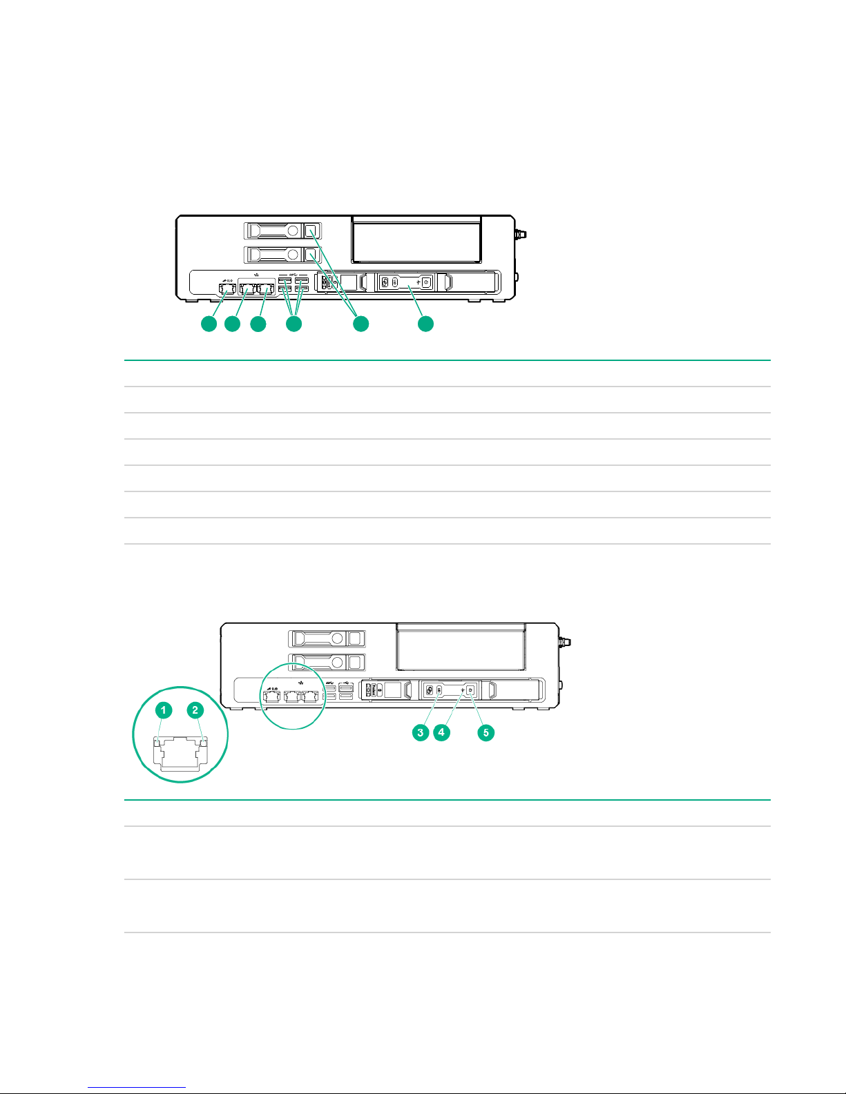
PCIe configuration
Front panel components
Item Description
1 iLO port
2 Network port 1
3 Network port 2
1
1
4 USB 3.0 ports
5 Drives
6 Cartridge
1
Network connections are available in 1G and 10G. The 1G is shown.
Front panel LEDs and buttons
Item Description Status
1 iLO and network port link
LED
• Green = Linked to network
• Off = No network connection
2 iLO and network port activity
LED
6 Component identification
• Flashing green = Network activity
• Off = No network activity
Table Continued
Page 7
Item Description Status
1
2 3
4
3 Cartridge UID LED/button
4 Cartridge health LED
5 Cartridge power LED
Right side components
• Blue = Cartridge ID is selected
• Flashing Blue = Cartridge firmware update is in
progress or iLO IRC is in use
• Off = Cartridge ID is not selected
• Green = Normal operation
• Flashing Amber = Degraded condition
• Flashing Red = Critical condition
• Off = No power
• Green = Normal operation
• Flashing green = iLO booting
• Amber = Standby operation
• Off= No power
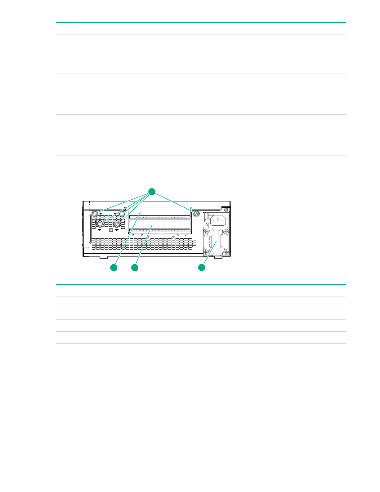
Item Description
1 Antenna connectors
2 PCIe slot 1
3 PCIe slot 2
4 Power supply
Right side components 7
Page 8
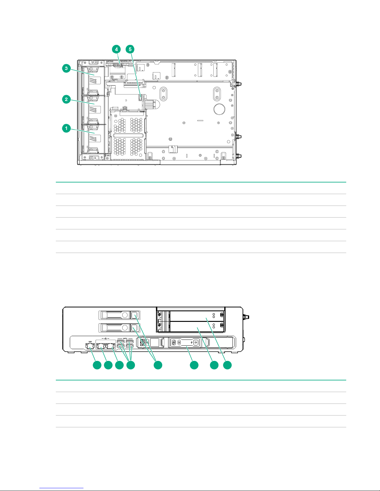
System board components
21
1 6 7 82 3 4 5
Item Description
1 Fan 1
2 Fan 2
3 Fan 3
4 Power distribution board
5 System battery
PXI/PXIe configuration
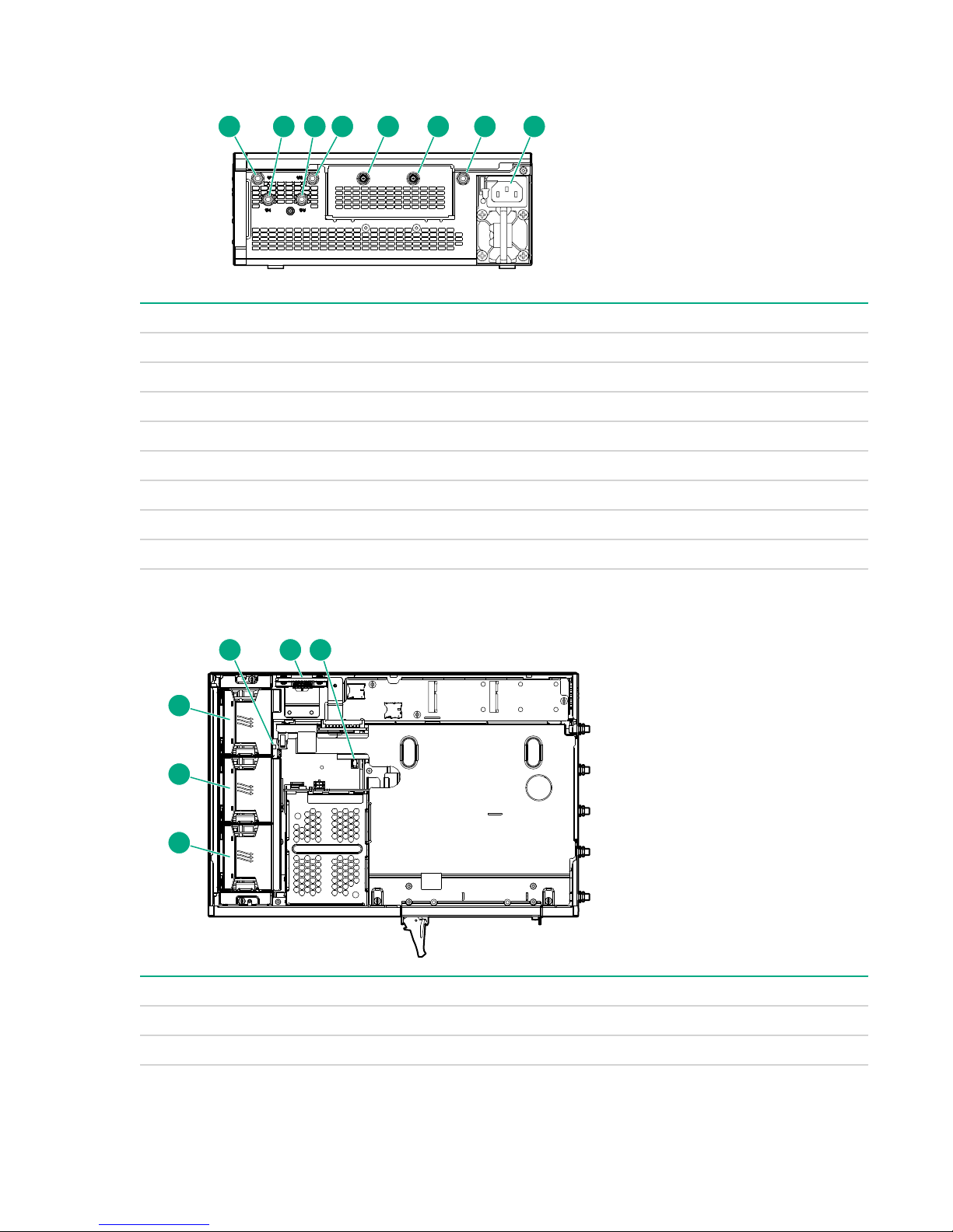
Front panel components
Item Description
1 iLO port
2 Network port 1
3 Network port 2
8 System board components
1
1
Table Continued
Page 9

Item Description
21
543
1 2
4 USB 3.0 ports (4)
5 Drives (2)
6 Cartridge
7 PXI/PXIe slot 3
8 PXI/PXIe slot 2
1
Network connections are available in 1G and 10G. The 1G is shown.
Front panel LEDs and buttons
Item Description Status
1 iLO and network port link
LED
2 iLO and network port activity
LED
3 Cartridge UID LED/button
• Green = Linked to network
• Off = No network connection
• Flashing green = Network activity
• Off = No network activity
• Blue = Cartridge ID is selected
• Flashing Blue = Cartridge firmware update is in
progress or iLO IRC is in use
• Off = Cartridge ID is not selected
4 Cartridge health LED
• Green = Normal operation
• Flashing Amber = Degraded condition
• Flashing Red = Critical condition
• Off = No power
5 Cartridge power LED
• Green = Normal operation
• Flashing green = iLO booting
• Amber = Standby operation
• Off= No power
Front panel LEDs and buttons 9
Page 10
Right side components
1 32 4 5 6 7 8
1
2
3
5 64
Item Description
1 Antenna connector
2 Antenna connector
3 Antenna connector
4 Antenna connector
5 REF in connector
6 REF out connector
7 Antenna connector
8 Power supply
System board components
Item Description
1 Fan 1
2 Fan 2
10 Right side components
Table Continued
Page 11
Item Description
3 Fan 3
4 DIP Switch
5 Power distribution board
6 System battery
1
The fan cage might have to be removed to access the switch
DIP switch
Position Default Function
1
S1 Off
Hot-plug drive LED definitions
When a drive is configured as part of a SmartArray and connected to a powered-up controller, the drive
LEDs indicate the condition of the drive. If no SmartArray adapter is present, then these drives will not be
hot pluggable, but will still show the activity LEDs.
Item LED Status Definition
1
Locate Solid blue The drive is being identified by a host application.
• Off = Fan normal mode
• On = Fan high mode
2
3
Activity
ring
Do not
remove
Flashing
blue
Rotating
green
Off No drive activity
Solid white Do not remove the drive. Removing the drive causes one or
Off Removing the drive does not cause a logical drive to fail.
The drive carrier firmware is being updated or requires an
update.
Drive activity
more of the logical drives to fail.
Table Continued
DIP switch 11
Page 12

4
Drive
Solid green The drive is a member of one or more logical drives.
status
Flashing
green
The drive is rebuilding or performing a RAID migration, strip size
migration, capacity expansion, or logical drive extension, or is
erasing.
Flashing
amber/
The drive is a member of one or more logical drives and predicts
the drive will fail.
green
Flashing
The drive is not configured and predicts the drive will fail.
amber
Solid amber The drive has failed.
Off The drive is not configured by a RAID controller.
12 Component identification
Page 13
Operations
This chapter describes the hardware operations carried out prior to and after installing or removing a
hardware option, or performing a server maintenance or troubleshooting procedure.
Before performing these hardware operations, review and observe the server warnings and cautions.
Install an AC power supply
Procedure
1. Align the power supply to the system.
2. Insert the power supply until it locks in place.
3. Connect the power cord and tie wrap the cable.
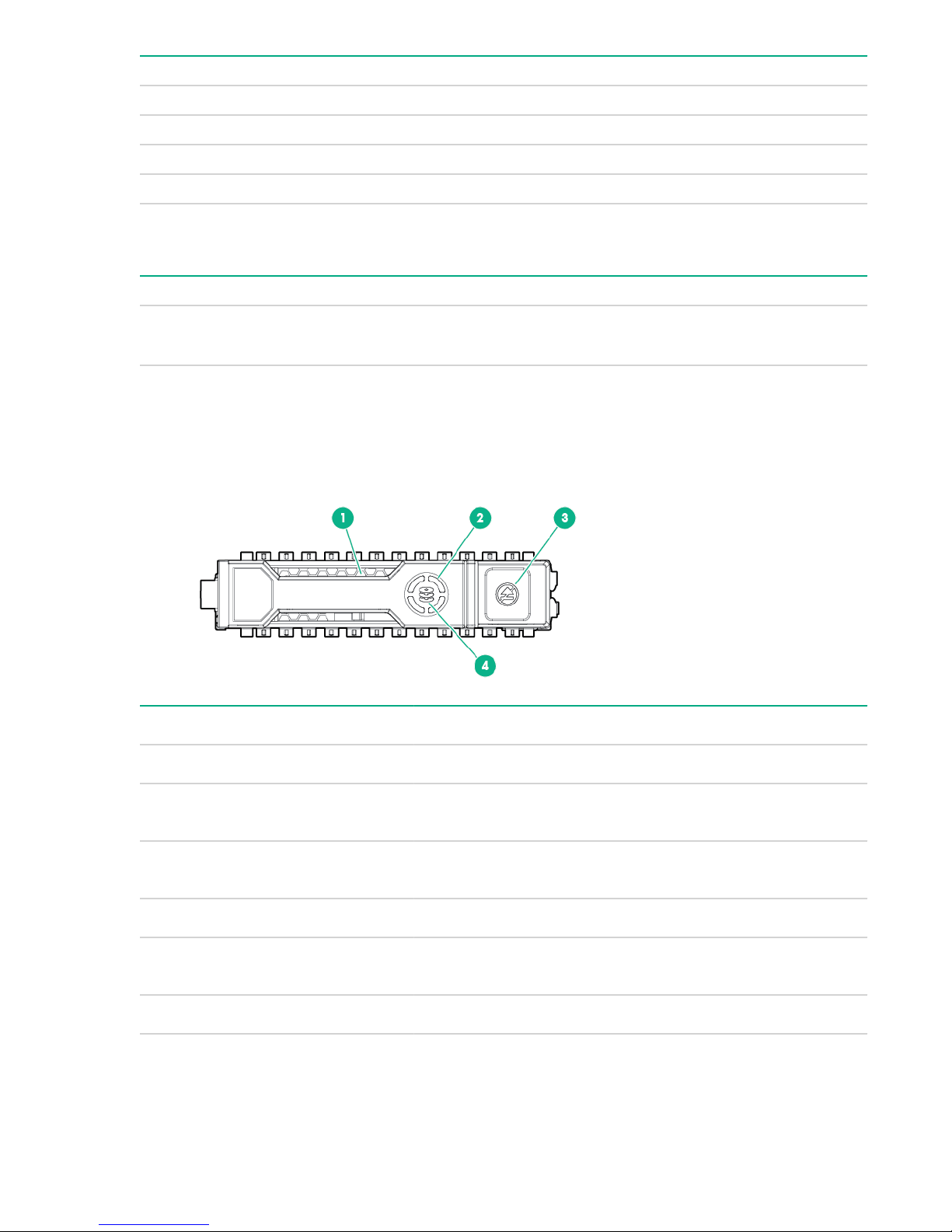
Install the DC power supply
Procedure
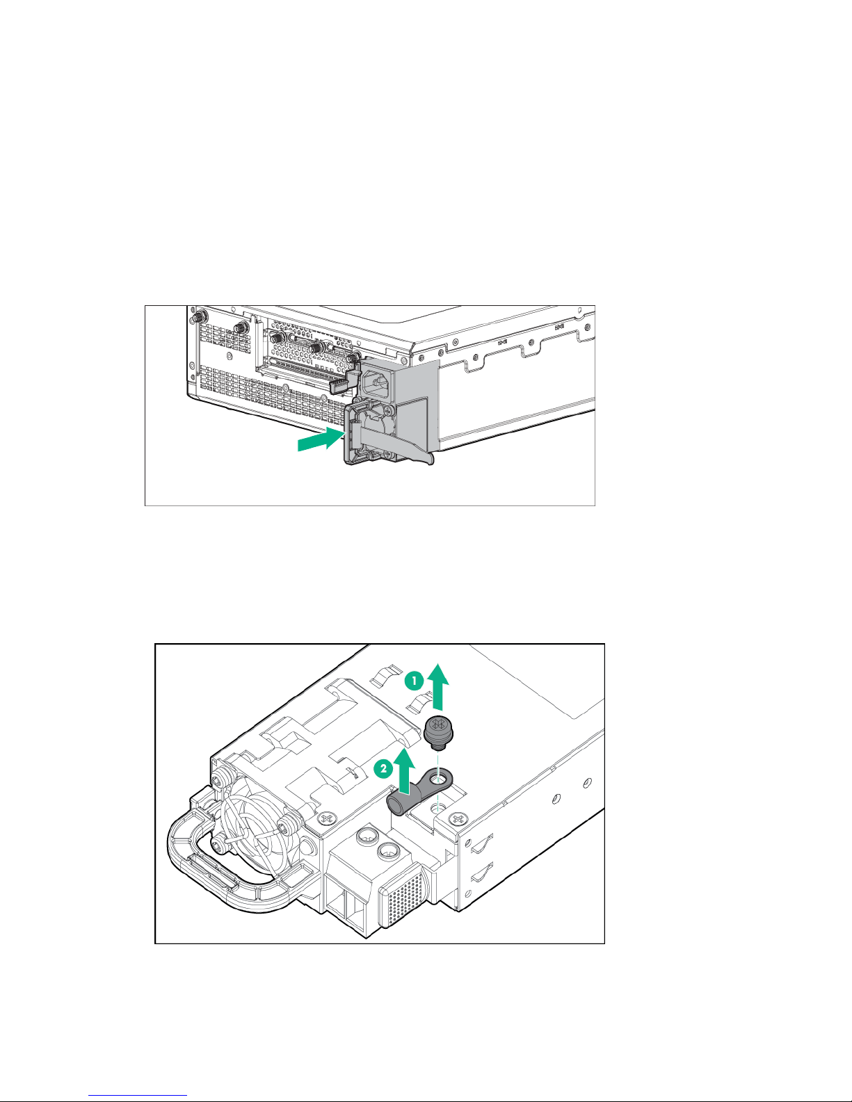
1. Remove the ring tongue from the top of the power supply.
2. Crimp the ring tongue to the ground cable from the -48V power source.
Operations 13
Page 14
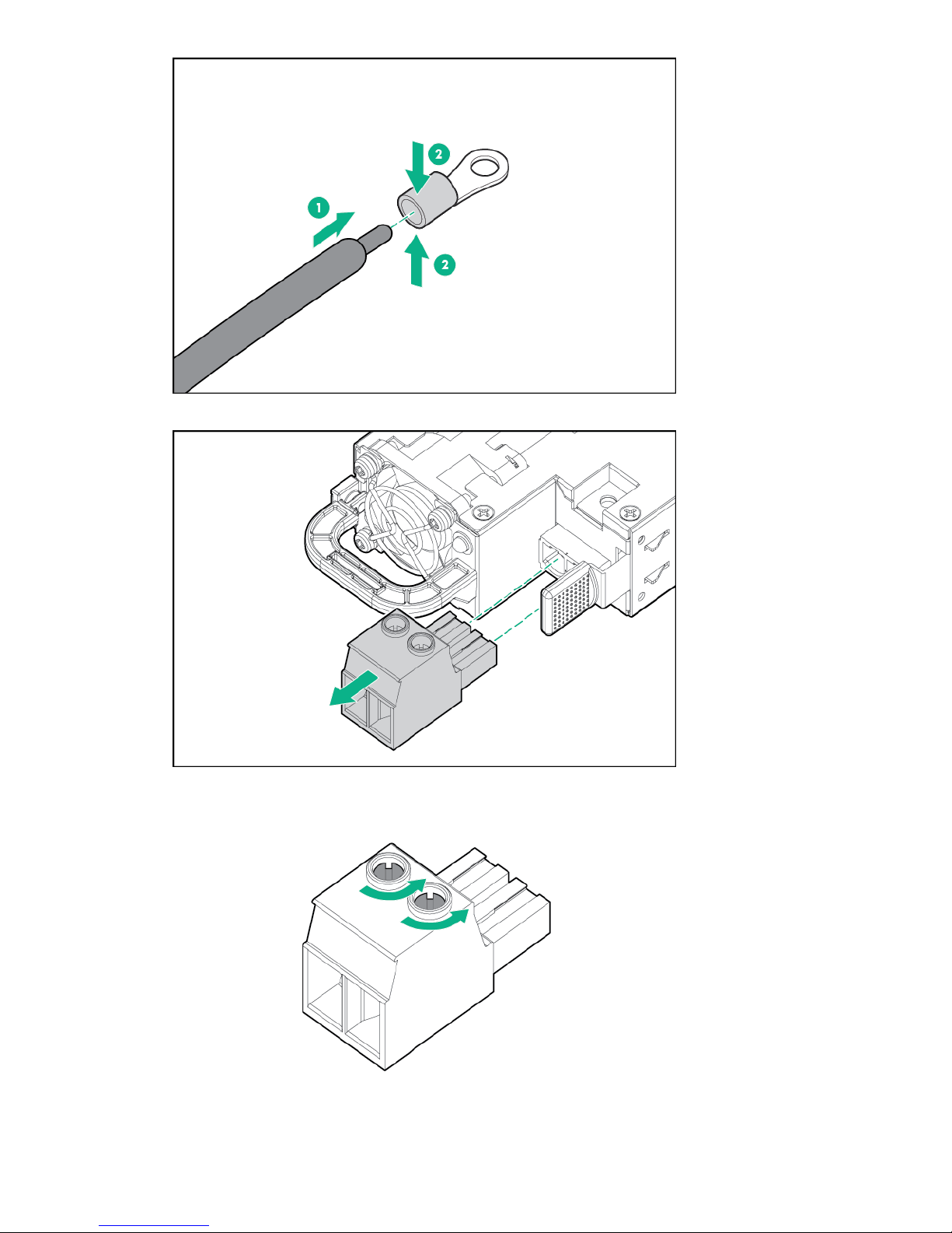
3. Remove the black connector from the rear of the power supply.
4. Loosen the screws on the connector.
14 Operations
Page 15
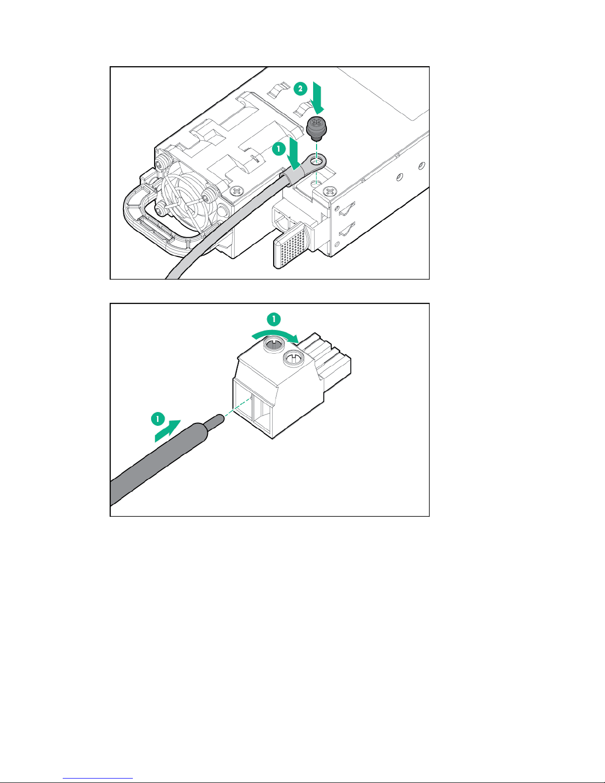
5. Attach the (earthed) cable to the ground screw and washer and tighten to 13 lb-in of torque. The
ground cable must be connected before connecting the -48V wire and return wire.
6. Insert the -48V wire into the left side of the connector and tighten the screw to 10 lb-in of torque.
7. Insert the return wire into the right side of the connector and tighten the screw to 10 lb-in of torque.
Operations 15
Page 16
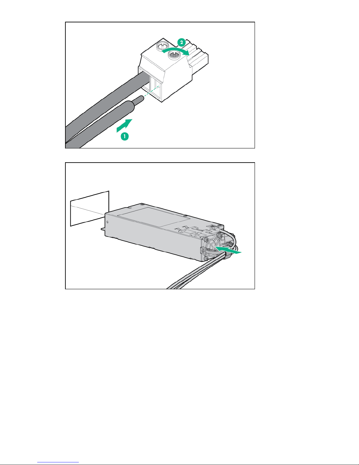
8. Insert the power supply into the power supply bay until it clicks into place.
9. Insert the connector into the power supply.
16 Operations
Page 17

10. Attach the cables to the power supply handle with the hook-and-loop strap.
11. Route the power cord. Use best practices when routing power cords and other cables. A cable
management arm is available to help with routing. To obtain a cable management arm, contact a
Hewlett Packard Enterprise authorized reseller.
12. Make sure the -48V DC power source is off or the PDU breaker is in the off position, and then
connect the power cord to the -48V DC power source or PDU.
13. Turn on the -48V power source or switch the PDU breaker to the on position to supply -48V to the
power supply.
14. Be sure that the green power supply LED is on.
Power down the system
About this task
Before powering down the system for any upgrade or maintenance procedures, back up critical system
data and programs.
Before performing chassis maintenance, shut down all cartridges installed in the system.
Power down the system 17
Page 18

Procedure
• Use one of the following methods to power down the system:
◦ Press and release the Power On/Standby button of the cartridges installed in the system.
This method initiates a controlled shutdown of applications and the OS before the system enters
standby mode.
◦ Press and hold the Power On/Standby button of the cartridges installed in the system for more than
4 seconds to force the system to power down.
This method forces the system to power down without properly exiting applications and the OS. If
an application stops responding, you can use this method to force a shutdown.
Verify the system is in standby mode and the system power LED is off.
Power up the system
About this task
If the system is connected to a power source, it powers up automatically by default. Generally, it has to be
powered up only after a manual shutdown. However, using iLO, cartridges can be individually configured
to not power up automatically.
Procedure
• Use one of the following methods to power up the system:
◦ Press the Power On/Standby button of the cartridge installed in the system.
◦ Remotely power up the system through iLO.
Mount the system
The following kits are available to mount your system:
• Wall mounting kit
• Rack mounting kit
• ETSI rack mounting kit
• Enterprise rack mounting kit
Dismount the system
Dismount the system, based on the mount installed:
• Dismounting the system from a wall mount
• Dismounting the system from a rack mount
• Dismounting the system from an ETSI rack mount
• Dismounting the system from an Enterprise rack mount
Dismounting the system from a wall mount
About this task
To dismount the system from a wall mount, slide the EL1000 system off the wall-mounting screws.
It is not necessary to remove the wall mounting plate from the EL1000 system. Hewlett Packard
Enterprise recommends having a cart to place the system upon, which allows you to service the system
without removing the wall mounting plate or cables.
Should you need to service the system in another location, perform the following steps.
18 Power up the system
Page 19
Procedure
1. Remove the four T-15 Torx screws securing the wall mounting plate to the bottom of the system.
2. Disconnect all cables.
Dismounting the system from a rack mount
Procedure
1. Loosen the 2 captive screws on the front of rack mount shelf.
2. Slide the EL1000 system and shelf out from the rack mounts to the front.
3. Unplug the power cable and disconnect all cables from the system.
4. Remove the system from the shelf assembly by lifting vertically.
Dismounting the system from an ETSI rack mount
Procedure
1. Loosen the 2 captive screws on the front of rack mount shelf.
2. Slide the EL1000 system and shelf out from the rack mounts to the front.
3. Unplug the power cable and disconnect all cables from the system.
4. Remove the system from the shelf assembly by lifting vertically.
Dismounting the system from an Enterprise rack mount
Procedure
1. Slide the system out of the rack.
2. Unplug the power cable and disconnect all cables from the system.
3. Remove the retention bracket from the Enterprise rack mount.
4. Lift and remove the system from the rack mount.
Remove the access panel
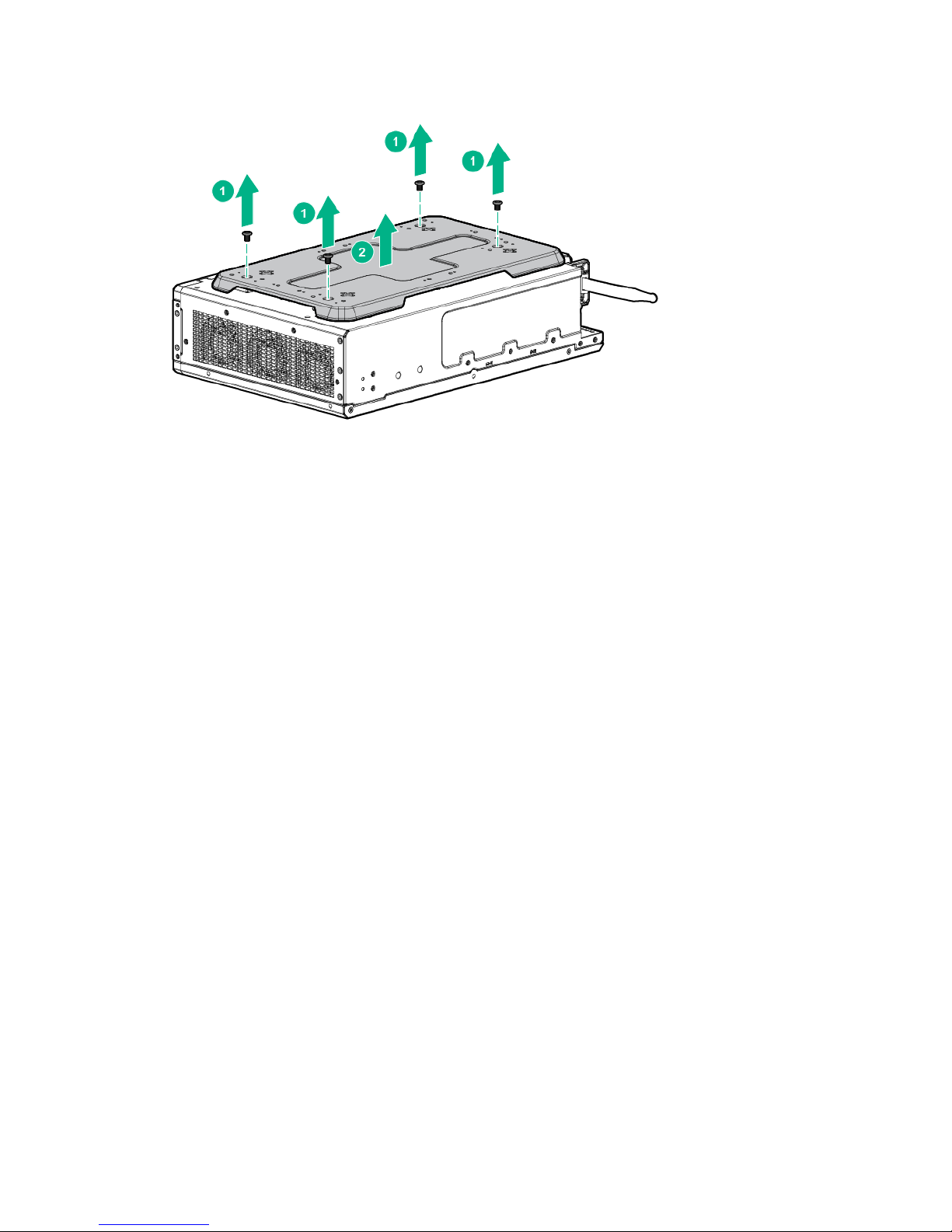
Procedure
• Using a Torx driver, remove the two T10 Torx screws securing the access panel to the system.
Dismounting the system from a rack mount 19
Page 20

Installing the fans
Procedure
1. Align the fan with the fan slots of the system.
2. Squeeze the tabs on either side of the fan, and then slide it into the bay until it clicks in place.
Installing the cartridge
About this task
No cartridges supported on the system support Legacy BIOS Boot mode. For more information, see the
user and maintenance guide for your cartridge.
Procedure
• Align and install the cartridge into the system.
20 Installing the fans
Page 21

Install the mini-PCIe adapter board
1
2
2
2
Procedure
1. Align the mini-PCIe adapter board to the system board.
2. Using a Torx driver, insert and tighten the three T-15 Torx screws to secure the adapter board to the
system board.
3. Connect the two cables from the mini-PCIe adapter board to the system board:
a. Connect the power cable.
b. Connect the drive cable.
Install the mini-PCIe adapter board 21
Page 22

Setup
This chapter describes the initial setup procedures to prepare the server for operation.
Optional services
Hewlett Packard Enterprise offers the HPE Foundation Care Next Business Day Exchange Service for
this product.
HPE Foundation Care Next Business Day Exchange Service provides a replacement product or part
delivered free of freight charges to your location the next business day after a call is opened and provides
support 24 hours per day, Monday through Sunday.
Hardware exchange offers a reliable and fast parts exchange service for eligible Hewlett Packard
Enterprise products. Specifically targeted at products that can easily be shipped and on which you can
easily restore data from backup files, HPE Foundation Care Next Business Day Exchange is a costefficient and convenient alternative to onsite support.
Replacement products or parts are new or equivalent to new in performance.
In addition, HPE Foundation Care Next Business Day Exchange provides electronic access to related
product and support information, enabling any member of your IT staff to locate commercially available
essential information.
For more information on HPE Foundation Care Next Business Day Exchange Service, see the
Packard Enterprise website.
Optimum environment
When installing the system, select a location that meets the environmental standards.
• Temperature requirements
• Power requirements
Temperature requirements
To ensure continued safe and reliable equipment operation, install or position the system in a wellventilated, climate-controlled environment.
Configuration Temperature
Chassis with cartridges installed, but no PCIe
cards/PXIe modules installed
Power requirements
Installation of this equipment must comply with local and regional electrical regulations governing the
installation of information technology equipment by licensed electricians. This equipment is designed to
operate in installations covered by NFPA 70, 1999 Edition (National Electric Code) and NFPA-75, 1992
(code for Protection of Electronic Computer/Data Processing Equipment). For electrical power ratings on
options, see the product rating label or the user documentation supplied with that option.
Hewlett
Operating temperature of up to 55°C (131°F)
More Information
Power supply specifications on page 51
22 Setup
Page 23

Installing hardware options
Install any hardware options before initializing the system. For options installation information, see the
option documentation. For system-specific information, see "Hardware options installation."
Registering the product
To experience quicker service and more efficient support, register the product at the
Enterprise Product Registration website.
Hewlett Packard
Installing hardware options 23
Page 24

Hardware options installation
Installing the wall mounting option kit
Procedure
1. Using the wall mount bracket, mark the locations for the wall mount screws.
2. Install the wall mount anchors and screws in the marked locations.
3. Align the wall mount bracket to the system.
4. Using a Torx driver, insert and tighten four T15 Torx screws to secure the bracket to the system.
5. Place the holes in the wall mount bracket over the wall mounting screws and slide to lock into place.
Installing the rack mounting option kit
Procedure
1. Align the rack mount bracket to the system.
2. Using a Torx driver, insert and tighten four T-10 Torx screws to secure the bracket to the system.
24 Hardware options installation
Page 25

3. Install the system in the rack mount.
Installing the ETSI rack mounting option kit
Procedure
1. Align the rack mount bracket to the system.
2. Using a Torx driver, insert and tighten four T-10 Torx screws to secure the bracket to the system.
3. Install the ETSI brackets to the rack:
a. Align the bracket to the rack rail.
b. Using a Torx driver, insert and tighten two T-20 Torx screws to secure each bracket to the rack rail.
Installing the ETSI rack mounting option kit 25
Page 26

4. Align the system to the ETSI bracket.
5. Secure the system in the ETSI rack mount.
Installing the Enterprise rack mounting option kit
Procedure
1. Install the rails on the rack.
For more information on installing the rack rails, see the Quick Deploy Rail System Installation
Instructions that ships with the rack hardware kit.
2. Install the cable management arm.
For more information on installing the cable management arm, see the HP 1U Cable Management
Arm Option Installation Instructions that ships with the cable management arm kit.
3. Install the Enterprise rack mount onto the rails.
4. Remove the system retention bracket from the Enterprise rack mount.
26 Installing the Enterprise rack mounting option kit
Page 27

1
2
2
5. Align and install the system.
6. Install the retention bracket.
Hardware options installation 27
Page 28

1
2
1
Installing the drive
Procedure
1. Align the drive to the drive bay, and slide it into the bay until it clicks in place.
2. Close the locking latch to secure the drive.
Installing the card options
Depending on the configuration of your system, perform one of the following procedures:
• Install the PCIe card
• Install the PXI/PXIe card
Install the PCIe card
About this task
The system supports optional PCIe cards.
28 Installing the drive
Page 29

Procedure
1. Remove power from the system.
2. If installed, remove the cartridge.
3. Remove the access panel.
4. Using a Torx driver, remove the three black T-15 Torx screws.
5. Lift the PCIe riser cage using the finger hold positions in the riser cage.
IMPORTANT:
The PCIe card is not hot-pluggable. The system must be powered down to install this card.
6. Disconnect the power cable.
7. Disconnect the hard drive backplane cable and any other cables that connect to the PCIe cards.
8. Align the PCIe card to the PCIe slot on the side of the system, and then slide it in until it clicks in place.
Hardware options installation 29
Page 30

Install the PXI/PXIe card
1
1
2
1
2
3
3
About this task
The system supports optional PXI cards.
NOTE:
The PXI/PXIe card is not hot-pluggable. The system must be powered down to install this card.
Procedure
1. Power down the system.
2. Remove the PXI/PXIe blank screws, and then remove the blank.
3. Align the PXI/PXIe card to the PXI/PXIe slot in the front panel.
4. Bend the tab and slide the PXI/PXIe card in until it clicks in place.
5. Install the PXI/PXIe card slot screws.
30 Install the PXI/PXIe card
Page 31

Installing the mini-PCIe module options
1
1
2
You can install the following mini-PCIe modules on the mini-PCIe adapter board:
• Up to two half-length mini-PCIe modules
• Up to two full-length mini-PCIe modules
Install a half-length mini-PCIe module option
About this task
You will need a half-length mini-PCIe module adapter provided with the WiFi option kit to install this
option.
Procedure
1. Install the adapter using the two holes of the half-length mini-PCIe module.
2. Insert the mini-PCIe module connector into the slot.
3. Using a Phillips screwdriver, insert and tighten the two screws to secure the mini-PCIe module to the
board.
Installing the mini-PCIe module options 31
Page 32

3
1
2
Installing a full-length mini-PCIe module
1
3
2
Procedure
1. Align the full-length mini-PCIe module with the full-length slot on the mini-PCIe adapter board.
2. Insert the mini-PCIe module connector into the slot.
3. Using a Phillips screwdriver, insert and tighten the two screws to secure the mini-PCIe module to the
board.
32 Installing a full-length mini-PCIe module
Page 33

Configuration
Accessing the System Utilities menu
About this task
To complete these steps, you need the HPE USB-to-serial cable (HPE part number 871947-B21).
Table 1: Settings for connecting USB cable to serial port
Specifications Value
Baud rate 115200
Data bits 8
Parity None
Stop bit 1 (8 N1)
Procedure
1. Power down the cartridge.
2. Connect the USB-to-serial cable to the system. The USB end is connected to a system USB port.
3. Attach the serial end of the cable to a serial port using a null modem cable. The other serial port may
be another USB-to-serial adapter on a different machine.
4. Power on the cartridge. The serial console output screen displays.
5. Press the ESC + 9 keys. The System Utilities menu displays.
Configuration 33
Page 34

Viewing or updating the DHCP address using the serial
console cable
Procedure
1. Access the System Utilities menu.
2. Navigate through the menu options System Configuration > iLO 4 Configuration Utility > Network
> DNS/DHCP, and press Enter. The Network Autoconfiguration screen displays.
3. View or update the DHCP settings.
4. To save any changes, press the F10 key.
5. After saving all settings, iLO prompts for a reset in order for any new settings to be used. Reset the
system.
Finding the IP address through DHCP
Procedure
1. Access the System Utilities menu.
2. Navigate through the menu options System Configuration > iLO 4 Configuration Utility > Network
Options.
3. The Network Options screen displays the IP address.
34 Viewing or updating the DHCP address using the serial console cable
Page 35

Setting the static IP address using the serial console cable
Procedure
1. Access the System Utilities menu.
2. Navigate through the menu options System Configuration > iLO 4 Configuration Utility > Network
Options. The Network Options screen displays.
3. Change DHCP Enable to OFF.
4. Configure the IP Address, Subnet Mask, and Gateway Address as required. The following image is
an example of a completed Network Options screen.
Setting the static IP address using the serial console cable 35
Page 36

5. Once completed, press ESC to back out of the menus. Save the settings when prompted.
6. After saving all settings, iLO prompts for a reset in order for the new settings to be used. Reset the
system.
36 Configuration
Page 37

Software and configuration utilities
Product QuickSpecs
For more information about product features, specifications, options, configurations, and compatibility, see
the product QuickSpecs on the
Supported operating systems and drivers matrix
To validate the minimum supported Operating System for a system platform, go to the Hewlett Packard
Enterprise website:
http://www.hpe.com/info/ossupport
To download the latest device drivers, go to the Hewlett Packard Enterprise Support Center website:
http://www.hpe.com/support/hpesc
HPE iLO
iLO is a remote server management processor embedded on the system boards of HPE ProLiant and
Synergy servers. iLO enables the monitoring and controlling of servers from remote locations. HPE iLO
management is a powerful tool that provides multiple ways to configure, update, monitor, and repair
servers remotely. iLO (Standard) comes preconfigured on HPE servers without an additional cost or
license.
Hewlett Packard Enterprise website.
Features that enhance server administrator productivity are licensed. For more information, see the iLO
documentation on the Hewlett Packard Enterprise website.
Active Health System
The HPE Active Health System provides the following features:
• Combined diagnostics tools/scanners
• Always on, continuous monitoring for increased stability and shorter downtimes
• Rich configuration history
• Health and service alerts
• Easy export and upload to Service and Support
The Active Health System monitors and records changes in the server hardware and system
configuration. The Active Health System assists in diagnosing problems and delivering rapid resolution if
server failures occur.
The Active Health System collects the following types of data:
• Server model
• Serial number
• Processor model and speed
• Storage capacity and speed
• Memory capacity and speed
• Firmware/BIOS
Active Health System does not collect information about Active Health System users' operations,
finances, customers, employees, partners, or data center, such as IP addresses, host names, user
names, and passwords. Active Health System does not parse or change operating system data from
third-party error event log activities, such as content created or passed through by the operating system.
Software and configuration utilities 37
Page 38

The data that is collected is managed according to the Hewlett Packard Enterprise Data Privacy policy.
For more information, see the Hewlett Packard Enterprise website.
The Active Health System, in conjunction with the system monitoring provided by Agentless Management
or SNMP Pass-thru, provides continuous monitoring of hardware and configuration changes, system
status, and service alerts for various server components.
The Agentless Management Service is available in the SPP, which can be downloaded from the Hewlett
Packard Enterprise website. The Active Health System log can be downloaded manually from iLO 4 or
HPE Intelligent Provisioning and sent to Hewlett Packard Enterprise.
For more information, see the following documents:
• iLO User Guide on the Hewlett Packard Enterprise website
• Intelligent Provisioning User Guide on the Hewlett Packard Enterprise website
Active Health System data collection
The Active Health System does not collect information about your operations, finances, customers,
employees, or partners.
Examples of data that is collected:
• Server model and serial number
• Processor model and speed
• Storage capacity and speed
• Memory capacity and speed
• Firmware/BIOS and driver versions and settings
The Active Health System does not parse or change operating system data from third-party error event
log activities (for example, content created or passed through the operating system).
Active Health System log
The data collected by the Active Health System is stored in the Active Health System Log. The data is
logged securely, isolated from the operating system, and separate from customer data.
When the Active Health System Log is full, new data overwrites the oldest data in the log.
It takes less than 5 minutes to download the Active Health System Log and send it to a Hewlett Packard
Enterprise support professional to help you resolve an issue.
When you download and send Active Health System data to Hewlett Packard Enterprise, you agree to
have Hewlett Packard Enterprise use the data for analysis, technical resolution, and quality
improvements. The data that is collected is managed according to the privacy statement, available on the
Hewlett Packard Enterprise website.
iLO RESTful API support
HPE iLO 4 firmware version 2.00 and later includes the iLO RESTful API. The iLO RESTful API is a
management interface that server management tools can use to perform configuration, inventory, and
monitoring of the ProLiant server via iLO. The iLO RESTful API uses basic HTTPS operations (GET, PUT,
POST, DELETE, and PATCH) to submit or return JSON-formatted data with iLO web server.
HPE iLO 4 2.30 and later is Redfish 1.0-conformant while remaining backward compatible with the
existing iLO RESTful API.
HPE iLO 4 supports the iLO RESTful API with ProLiant Gen8 and later servers. For more information
about the iLO RESTful API, see the Hewlett Packard Enterprise website.
38 Active Health System data collection
Page 39

Integrated Management Log
The IML records hundreds of events and stores them in an easy-to-view form. The IML timestamps each
event with 1-minute granularity.
You can view recorded events in the IML in several ways, including the following:
• From within HPE SIM
• From within UEFI System Utilities
• From within the Embedded UEFI shell
• From within operating system-specific IML viewers:
◦ For Windows: IML Viewer
◦ For Linux: IML Viewer Application
• From within the iLO web interface
• From within Insight Diagnostics
HPE Edgeline Component Pack
The HPE Edgeline Component Pack is a comprehensive firmware solution tested on the Edgeline System
and delivered as a compressed file. The compressed file includes all the component files needed to
update an Edgeline System. Users deploy the firmware updates contained in the HPE Edgeline
Component Pack using the included Smart Update Manager, or by updating using the firmware update
capability of the iLO 4 on each server cartridge. Download the latest pack from the
Enterprise website.
Hewlett Packard
HP Smart Update Manager
HP SUM is an application included with the HPE Edgeline Component Pack that provides a web-based
GUI for installing and updating firmware on many Hewlett Packard Enterprise products, including the
Edgeline System. HP SUM has an integrated discovery engine that finds the installed hardware and
current versions of firmware in use on nodes you identify. The application installs updates in the correct
order and ensures that all dependencies are met before deploying an update, and prevents an installation
if there are version-based dependencies that it cannot resolve.
The version of HP SUM included with each HPE Edgeline Component Pack release is designed to be the
best solution for installing Edgeline System firmware updates. Always use the included version of HP
SUM for Edgeline System updates. For more information, see the HPE Edgeline Component Pack
Update Guide in the Hewlett Packard Enterprise Information Library.
UEFI System Utilities
The UEFI System Utilities is embedded in the system ROM. The UEFI System Utilities enable you to
perform a wide range of configuration activities, including:
• Configuring system devices and installed options
• Enabling and disabling system features
• Displaying system information
• Selecting the primary boot controller
• Configuring memory options
• Selecting a language
• Launching other preboot environments such as the Embedded UEFI Shell and Intelligent Provisioning
For more information, see the UEFI System Utilities user guide for your product on the Hewlett Packard
Enterprise website.
To access mobile-ready online help for the UEFI System Utilities and UEFI Shell, scan the QR code at the
bottom of the screen. For on-screen help, press the F1 key.
Integrated Management Log 39
Page 40

Using UEFI System Utilities
To use the System Utilities, use the following keys.
Action Key
Access System Utilities F9 during server
Navigate menus Up and Down
Select items Enter
Save selections F10
POST
arrows
Access Help for a highlighted configuration
1
option
1
Scan the QR code on the screen to access online help for the UEFI
System Utilities and UEFI Shell.
Default configuration settings are applied to the server at one of the following times:
• Upon the first system power-up
• After defaults have been restored
Default configuration settings are sufficient for typical server operations; however, you can modify
configuration settings as needed. The system prompts you for access to the UEFI System Utilities each
time the system is powered up.
Flexible boot control
This feature enables you to do the following:
• Add Boot Options:
◦ Browse all FAT16 and FAT32 file systems.
◦ To add a new UEFI boot option, select an X64 UEFI application with an .EFI extension. For
example, adding an OS boot loader or other UEFI application as a new UEFI boot option.
The new boot option is appended to the boot-order list. When you select a file, you are prompted to
enter the boot option description. This description, and any optional data to be passed to an .EFI
application, is then displayed in the boot menu.
• Boot to System Utilities
F1
After pre-POST, the boot options screen appears. During this time, you can access the UEFI System
Utilities by pressing the F9 key.
• Choose between supported modes:
◦ Legacy BIOS Boot Mode
◦ UEFI Boot Mode
IMPORTANT:
If the default boot mode settings are different than the user-defined settings, the system might
not boot the OS installation if the defaults are restored. To avoid this issue, use the User
Defined Defaults feature in UEFI System Utilities to override the factory default settings.
For more information, see the UEFI System Utilities user guide for your product on the Hewlett Packard
Enterprise Information Library.
40 Using UEFI System Utilities
Page 41

Restoring and customizing configuration settings
You can reset all configuration settings to the factory default settings, or you can restore and use the
system default configuration settings.
You can also configure default settings as necessary, and then save the configuration as the custom
default configuration. When the system loads the default settings, it uses the custom default settings
instead of the factory defaults.
Secure Boot configuration
Secure Boot is integrated in the UEFI specification on which the Hewlett Packard Enterprise
implementation of UEFI is based. Secure Boot is implemented in the BIOS and does not require special
hardware. Secure Boot ensures that each component launched during the boot process is digitally
signed. Secure Boot also ensures that the signature is validated against a set of trusted certificates
embedded in the UEFI BIOS. Secure Boot validates the software identity of the following components in
the boot process:
• UEFI drivers loaded from PCIe cards
• UEFI drivers loaded from mass storage devices
• Preboot UEFI shell applications
• OS UEFI boot loaders
When enabled, only firmware components and operating systems with boot loaders that have an
appropriate digital signature can execute during the boot process. Only operating systems that support
Secure Boot and have an EFI boot loader signed with one of the authorized keys can boot. For more
information about supported operating systems, see the UEFI System Utilities and Shell release notes for
your system on the Hewlett Packard Enterprise website.
A physically present user can customize the certificates embedded in the UEFI BIOS by adding or
removing their own certificates.
When Secure Boot is enabled, the System Maintenance Switch does not restore all manufacturing
defaults when set to the ON position. For security reasons, the following are not restored to defaults when
the System Maintenance Switch is in the ON position:
• Secure Boot is not disabled and remains enabled.
• The Boot Mode remains in UEFI Boot Mode even if the default boot mode is Legacy Boot Mode.
• The Secure Boot Database is not restored to its default state.
• iSCSI Software Initiator configuration settings are not restored to defaults.
Embedded UEFI shell
The system BIOS in all ProLiant Gen9 servers includes an Embedded UEFI Shell in the ROM. The UEFI
Shell environment provides an API, a command-line prompt, and a set of CLIs that allow scripting, file
manipulation, and system information. These features enhance the capabilities of the UEFI System
Utilities.
For more information, see the following documents:
• UEFI Shell User Guide for HPE ProLiant Gen9 Servers on the Hewlett Packard Enterprise website
• UEFI Shell Specification on the UEFI website
Embedded Diagnostics option
The system BIOS in all ProLiant Gen9 servers includes an Embedded Diagnostics option in the ROM.
The Embedded Diagnostics option can run comprehensive diagnostics of the server hardware, including
processors, memory, drives, and other server components.
Restoring and customizing configuration settings 41
Page 42

For more information on the Embedded Diagnostics option, see the UEFI System Utilities user guide for
your system on the Hewlett Packard Enterprise website.
iLO RESTful API support for UEFI
The ProLiant Gen9 servers include support for a UEFI-compliant System BIOS, along with UEFI System
Utilities and Embedded UEFI Shell preboot environments. ProLiant Gen9 servers also support configuring
the UEFI BIOS settings using the iLO RESTful API, a management interface that server management
tools can use to perform configuration, inventory, and monitoring of a ProLiant server. The iLO RESTful
API uses basic HTTPS operations (GET, PUT, POST, DELETE, and PATCH) to submit or return JSONformatted data with iLO web server.
For more information about the iLO RESTful API and the RESTful Interface Tool, see the Hewlett
Packard Enterprise website.
Re-entering the server serial number and product ID
About this task
After you replace the system board, you must re-enter the system serial number and the product ID:
Procedure
1. During the system startup sequence, press the F9 key to access UEFI System Utilities.
2. Select System Configuration > BIOS/Platform Configuration (RBSU) > Advanced Options >
Advanced System ROM Options > Serial Number, and then press the Enter key.
3. Enter the serial number and press the Enter key.
The following message appears:
The serial number should only be modified by qualified service personnel.
This value should always match the serial number located on the chassis.
4. To clear the warning, press the Enter key.
5. Enter the serial number and press the Enter key.
6. Select Product ID.
The following warning appears:
Warning: The Product ID should ONLY be modified by qualified service
personnel. This value should always match the Product ID located on the
chassis.
7. Enter the product ID and press the Enter key.
8. To confirm exiting System Utilities, press the F10 key.
The system automatically reboots.
42 iLO RESTful API support for UEFI
Page 43

Troubleshooting
HPE Edgeline Troubleshooting Guide
The HPE Edgeline System Troubleshooting Guide provides procedures for resolving common problems
and comprehensive courses of action for fault isolation and identification, issue resolution, and software
maintenance on the Edgeline System. The document is available in the
Information Library.
Hewlett Packard Enterprise
Troubleshooting 43
Page 44

Battery
Battery specifications
Feature Specification
Type Maintenance-free, sealed, CR2032 lithium manganese dioxide button battery
Voltage 3.0 V
Replace the system battery
Procedure
1. Locate the battery on the system board:
• PCIe configuration system board
• PXIe configuration system board
2. Slightly push the metal tab, and then use the small flat-nose pliers to remove the system battery from
its socket.
3. Slightly push the metal tab, then install the system battery in the socket.
44 Battery
Page 45

For more information about battery replacement or proper disposal, contact an authorized reseller or an
authorized service provider.
Battery 45
Page 46

Warranty and regulatory information
Warranty information
HPE ProLiant and x86 Servers and Options
HPE Enterprise Servers
HPE Storage Products
HPE Networking Products
Regulatory information
Safety and regulatory compliance
For important safety, environmental, and regulatory information, see Safety and Compliance Information
for Server, Storage, Power, Networking, and Rack Products, available at the Hewlett Packard Enterprise
website (http://www.hpe.com/support/Safety-Compliance-EnterpriseProducts).
Belarus Kazakhstan Russia marking
Manufacturer and Local Representative Information
Manufacturer information:
• Hewlett Packard Enterprise Company, 3000 Hanover Street, Palo Alto, CA 94304 U.S.
Local representative information Russian:
• Russia:
• Belarus:
• Kazakhstan:
Local representative information Kazakh:
• Russia:
• Belarus:
46 Warranty and regulatory information
Page 47

• Kazakhstan:
Manufacturing date:
The manufacturing date is defined by the serial number.
CCSYWWZZZZ (serial number format for this product)
Valid date formats include:
• YWW, where Y indicates the year counting from within each new decade, with 2000 as the starting
point; for example, 238: 2 for 2002 and 38 for the week of September 9. In addition, 2010 is indicated
by 0, 2011 by 1, 2012 by 2, 2013 by 3, and so forth.
• YYWW, where YY indicates the year, using a base year of 2000; for example, 0238: 02 for 2002 and
38 for the week of September 9.
Turkey RoHS material content declaration
Ukraine RoHS material content declaration
Turkey RoHS material content declaration 47
Page 48

Electrostatic discharge
Preventing electrostatic discharge
About this task
To prevent damaging the system, be aware of the precautions you must follow when setting up the
system or handling parts. A discharge of static electricity from a finger or other conductor may damage
system boards or other static-sensitive devices. This type of damage may reduce the life expectancy of
the device.
Procedure
• Avoid hand contact by transporting and storing products in static-safe containers.
• Keep electrostatic-sensitive parts in their containers until they arrive at static-free workstations.
• Place parts on a grounded surface before removing them from their containers.
• Avoid touching pins, leads, or circuitry.
• Always be properly grounded when touching a static-sensitive component or assembly.
Grounding methods to prevent electrostatic discharge
Several methods are used for grounding. Use one or more of the following methods when handling or
installing electrostatic-sensitive parts:
• Use a wrist strap connected by a ground cord to a grounded workstation or computer chassis. Wrist
straps are flexible straps with a minimum of 1 megohm ±10 percent resistance in the ground cords. To
provide proper ground, wear the strap snug against the skin.
• Use heel straps, toe straps, or boot straps at standing workstations. Wear the straps on both feet
when standing on conductive floors or dissipating floor mats.
• Use conductive field service tools.
• Use a portable field service kit with a folding static-dissipating work mat.
If you do not have any of the suggested equipment for proper grounding, have an authorized reseller
install the part.
For more information on static electricity or assistance with product installation, contact the Hewlett
Packard Enterprise Support Center.
48 Electrostatic discharge
Page 49

Specifications
Product QuickSpecs
For more information about product features, specifications, options, configurations, and compatibility, see
the product QuickSpecs on the
Environmental specifications
Table 2: Standard specifications
Specification Value
Temperature range
1
Hewlett Packard Enterprise website.
—
Operating
Nonoperating -30°C to 60°C (-22°F to 140°F)
Relative humidity (noncondensing) —
Operating 8% to 90% at 28°C (82.4°F) maximum wet bulb
Non-Operating 5% to 95% at 38.7°C (101.7°F) maximum wet bulb
1
All temperature ratings shown are for sea level. An altitude derating of 1.0°C per 304.8 m (1.8°F per
1,000 ft) to 3,048 m (10,000 ft) is applicable. No direct sunlight allowed. Maximum rate of change is
20°C per hour (36°F per hour).
10°C to 35°C (50°F to 95°F)
temperature
temperature
Table 3: ASHRAE Class A3 specifications
Specification Value
Temperature range
Operating
Nonoperating -30°C to 60°C (-22°F to 140°F)
Relative humidity (noncondensing)
1
—
5°C to 40°C (41°F to 104°F)
—
Operating 8% to 90% at 28°C (82.4°F) maximum wet bulb
Non-Operating 5% to 95% at 38.7°C (101.7°F) maximum wet bulb
1
All temperature ratings shown are for sea level. Good for 40°C operation up to 1,828 m (6,000 ft) with
no altitude de-rating. No restriction on product configurations. Abnormal configurations, allowed for up
to 96 hours at one time, no more than 15 days maximum per year. Operation above 40°C (104°F) up to
55°C (131°F), no altitude de-rating, 1,828 m (6,000 ft) limit. Some components could be outside the
thermal maximum limits. System must be kept running, processor throttling is allowed. Abnormal
conditions allow for operation down to -5°C (23°F).
temperature
temperature
Specifications 49
Page 50

Table 4: ASHRAE Class A4 specifications
Specification Value
Temperature range
1
—
Operating
5°C to 45°C (41°F to 113°F)
Nonoperating -30°C to 60°C (-22°F to 140°F)
Relative humidity (noncondensing)
—
Operating 8% to 90% at 28°C (82.4°F) maximum wet bulb
temperature
Non-Operating 5% to 95% at 38.7°C (101.7°F) maximum wet bulb
temperature
1
All temperature ratings shown are for sea level. An altitude derating of 1.0°C per 125 m (1.8°F per 410
ft) to 900 m (2,953 ft) is applicable. No direct sunlight allowed. Maximum rate of change is 20°C per
hour (36°F per hour). No restrictions on product configurations except for rotating hard drives. PCI cards
must be rated for continuous operation with 60°C cooling air. Not rated for operation over 3,030 m
(10,000 ft).
Table 5: Extended Edgeline specifications
Specification Value
Temperature range
Operating
Nonoperating -30°C to 60°C (-22°F to 140°F)
1
—
0°C to 55°C (32°F to 131°F)
Relative humidity (noncondensing)
—
Operating 8% to 90% at 28°C (82.4°F) maximum wet bulb
temperature
Non-Operating 5% to 95% at 38.7°C (101.7°F) maximum wet bulb
temperature
1
All temperature ratings shown are for sea level. An altitude derating of 1.0°C per 304.8 m (1.8°F per
1,000 ft) to 3,048 m (10,000 ft) is applicable. No direct sunlight allowed. Maximum rate of change is
20°C per hour (36°F per hour).
50 Specifications
Page 51

Environmental specifications-system components support matrix
Environment
al
specification
Standard
Operating
Support
Extended
Ambient 40°C
Operating
Support status
Base
Fans SFF drives SATA M.2
system
Yes Yes (with
redundanc
y)
Yes Yes (with
redundanc
2
y)
drives
NVME M.2
drives
PCIe I/O
cards
PXIe I/O
cards
Yes Yes Yes Yes Yes (up to
38 W)
Yes Yes Yes Yes Yes (up to
38 W)
Support
(ASHRAE
Class A3
Compliant)
Extended
Ambient 45°C
Operating
Yes Yes (with
redundanc
2
y)
Yes (less than
8 W)
Yes Yes
3
Yes Yes (up to
38 W)
Support
(ASHRAE
Class A4
Compliant)
Extended
Edgeline 0°C
to 55°C
Yes
4
Yes (with
redundanc
2
y)
No Yes No Yes
5
Yes (up to
38 W)
Operating
Support
1
Maximum altitude is 2,000 m (800 mbar) (at 25 °C ambient temperature)
2
Upon fan failure, the servers in the system might have reduced performance.
3
M.2 drive might exceed its spec by 2°C to 3°C and have slight throttling.
4
Near 55°C inlet ambient temperature, when the CPU is stressed at 100%, the HPE m510 -16c server
might have reduced performance.
5
The PCI card must have inlet spec rated at 65°C or higher, and an air speed of 375 ft/min.
1
1
1
1
Mechanical specifications
Specification Value
Length 87.4 mm (3.44 in)
Width 338 mm (13.30 in)
Depth 234 mm (9.20 in)
Weight 7.5 kg (16.53 lb)
Power supply specifications
Environmental specifications-system components support matrix 51
Page 52

HPE 500W Flex Slot Platinum Hot Plug Power Supply
Input voltage range (V rms) 100-240
Frequency range (Nominal) (Hz) 50-60
Nominal input voltage (V rms) 100 120 127 200 208 220 230 240
Maximum rated output wattage
500 500 500 500 500 500 500 500
rating (Watts)
Nominal input current (A rms) 5.6 4.6 4.3 2.7 2.6 2.5 2.4 2.3
Maximum rated input wattage
558 550 543 539 538 538 537 537
rating (Watts)
Maximum rated VA (Volt-Amp) 564 556 549 544 544 543 542 542
Efficiency (%) 89.6 90.9 92.1 92.8 92.9 93.0 93.1 93.1
Power factor 0.99 0.99 0.99 0.99 0.99 0.99 0.99 0.99
Leakage current (mA) 0.32 0.38 0.40 0.63 0.65 0.69 0.72 0.75
Maximum inrush current (A peak) 30 30 30 30 30 30 30 30
Maximum inrush current duration
10 10 10 10 10 10 10 10
(ms)
Maximum British Thermal Unit
1904 1877 1853 1839 1837 1834 1832 1832
rating (BTU-Hr)
HPE 800W Flex -48VDC Hot Plug Power Supply
Input voltage range (V DC) -40 to -72
Frequency range (Nominal) (Hz) DC
Nominal input voltage (V DC) -40 -48 -72
Maximum rated output wattage
800 800 800
rating (Watts)
Nominal input current (A DC) 22.0 18.1 11.9
Maximum rated input wattage
882 871 858
rating (Watts)
Maximum rated VA (Volt-Amp) 882 871 858
Efficiency (%) 90.7 91.9 93.2
Power factor 1.0 1.0 1.0
Leakage current (mA) 0.0 0.0 0.0
Maximum inrush current (A peak) 30 30 30
Maximum inrush current duration
10 10 10
(ms)
Maximum British Thermal Unit
3008 2971 2929
rating (BTU-Hr)
52 Specifications
Page 53

PXI/PXIe specifications
NOTE: Specifications are subject to change without notice.
Electrical load regulation specifications
Voltage (V) Load regulation (%)
+3.3 <5
+12 <5
+5 <5
-12 <5
Chassis cooling specifications
Specification Value
Module cooling system Forced air circulation (positive pressurization)
Airflow From front to rear
through three fans with High/Auto speed selector.
Launch Recipe supports this.
Pollution specifications
Specifications Value
Pollution degree 2
For indoor use only in a climate-controlled environment.
Shock and vibration specifications
Specification Value
Operational shock 30 g peak, half-sine, 11 ms pulse
Random vibration 5 Hz to 500 Hz, 0.3 g rms
Acoustic emission specifications
Acoustic noise
Acoustic noise specifications for the following base configurations are available.
Table 6: Base configuration 1 (m510)
Component Quantity Specification
Cartridge 4 m510
DIMMs/cartridge 4 Any
Table Continued
PXI/PXIe specifications 53
Page 54

Component Quantity Specification
SATA M.2/cartridge 1 64 GB
NVME M.2/cartridge 0 NA
PXI 4 PXI 6341
PSU 2 800 W AC
Table 7: Base configuration 2 (m710x)
Component Quantity Specification
Cartridge 4 m710x
DIMMs/cartridge 4 Any
SATA M.2/cartridge 1 64 GB
NVME M.2/cartridge 0 NA
PXI 4 PXI 6341
PSU 2 800 W AC
The LWAd and LpAm when the system is operating in a 23°C ambient environment are provided in the
following tables. Noise emissions were measured in accordance with ISO 7779 (ECMA 74) and declared
in accordance with ISO 9296 (ECMA 109).
Table 8: Acoustic noise when system is idle
system configuration LWAd (B) LpAm (dBA)
Base 1 8 64.6
Base 2 8 64.6
Table 9: Acoustic noise when system is operating
system configuration LWAd (B) LpAm (dBA)
Base 1 8 64.6
Bae 2 8 64.6
NOTE:
If used in a manner not described in this document, the protection provided by the system can be
impaired.
54 Specifications
Page 55

HPE EMC compliance testing
Emissions classification FCC rating Class A
EMC Normative standards
NOTE:
Product conformance to cited product specifications is based on sample (type) testing, evaluation,
or assessment. This product or family of products is eligible to bear the appropriate compliance
logos and statements.
System synchronization clock specifications
• CISPR 22
• EN55022
• EN55024
• FCC CFR 47
• Pt 15
• ICES-003
• CNS13438
• K22
• K24
• EN 61000-3-2
• EN 61000-3-3
• EN 60950-1
• IEC 60950-1
10 MHz system reference clock: PXI_CLK10
Specification Value
Maximum slot-to-slot skew 1 ns
Accuracy ±25 ppm max (guaranteed over the operating
temperature range)
Maximum jitter 5 ps RMS phase jitter (10 Hz to 1 MHz range)
Duty factor 45% to 55%
Unloaded signal swing 3.3 V ±0.3 V
NOTE:
For other specifications, see 'PXI-1 Hardware Specification' at the PXI Systems Alliance website
(http://www.pxisa.org/userfiles/files/Specifications/PXIHWSPEC22.pdf).
100 MHz system reference clock: PXIe_CLK100 and PXIe_SYNC100
Specification Value
Maximum slot-to-slot skew 200 ps
Accuracy ±25 ppm max (guaranteed over the operating
temperature range)
Table Continued
HPE EMC compliance testing 55
Page 56

Specification Value
Maximum jitter 5 ps RMS phase jitter (10 Hz to 12 kHz range); 5
ps RMS phase jitter (12 kHz to 20 MHz range)
Duty factor for PXIe_CLK100 45% to 55%
Absolute single-ended voltage swing (when each
400 mV to 1,000 mV
line in the differential pair has 50 W termination to
1.30 V or Thévenin equivalent)
NOTE:
For other specifications, see 'PXI-5 PXI Express Hardware Specification' at the PXI Systems
Alliance website (http://www.pxisa.org/userfiles/files/Specifications/
PXIEXPRESS_HW_SPEC_R1.PDF).
External 10 MHz reference out (SMA on front panel of chassis)
Specification Value
Accuracy ±25 ppm max (guaranteed over the operating
temperature range)
Maximum jitter 5 ps RMS phase jitter (10 Hz to 1 MHz range)
Output amplitude 1 VPP ±20% square wave into 50 Ω 2 VPP
unloaded
Output impedance 50 Ω ±5 Ω
External clock source
Specification Value
Frequency 10 MHz ±100 PPM
Input amplitude —
Front panel BNC 200 mVPP to 5 VPP square-wave or sine-wave
Front panel SMA input impedance 50 Ω ± 5 Ω
56 Specifications
Page 57

Support and other resources
Websites
Hewlett Packard Enterprise Information Library
•
• Hewlett Packard Enterprise Support Center
• Contact Hewlett Packard Enterprise Worldwide
• Subscription Service/Support Alerts
• Software Depot
• Customer Self Repair
• Insight Remote Support
• Serviceguard Solutions for HP-UX
• Single Point of Connectivity Knowledge (SPOCK) Storage compatibility matrix
• Storage white papers and analyst reports
Accessing Hewlett Packard Enterprise Support
• For live assistance, go to the Contact Hewlett Packard Enterprise Worldwide website:
http://www.hpe.com/assistance
• To access documentation and support services, go to the Hewlett Packard Enterprise Support Center
website:
http://www.hpe.com/support/hpesc
Information to collect
• Technical support registration number (if applicable)
• Product name, model or version, and serial number
• Operating system name and version
• Firmware version
• Error messages
• Product-specific reports and logs
• Add-on products or components
• Third-party products or components
Support and other resources 57
Page 58

Accessing updates
• Some software products provide a mechanism for accessing software updates through the product
interface. Review your product documentation to identify the recommended software update method.
• To download product updates:
Hewlett Packard Enterprise Support Center
www.hpe.com/support/hpesc
Hewlett Packard Enterprise Support Center: Software downloads
www.hpe.com/support/downloads
Software Depot
www.hpe.com/support/softwaredepot
• To subscribe to eNewsletters and alerts:
www.hpe.com/support/e-updates
• To view and update your entitlements, and to link your contracts and warranties with your profile, go to
the Hewlett Packard Enterprise Support Center More Information on Access to Support Materials
page:
www.hpe.com/support/AccessToSupportMaterials
IMPORTANT:
Access to some updates might require product entitlement when accessed through the Hewlett
Packard Enterprise Support Center. You must have an HPE Passport set up with relevant
entitlements.
Customer self repair
Hewlett Packard Enterprise customer self repair (CSR) programs allow you to repair your product. If a
CSR part needs to be replaced, it will be shipped directly to you so that you can install it at your
convenience. Some parts do not qualify for CSR. Your Hewlett Packard Enterprise authorized service
provider will determine whether a repair can be accomplished by CSR.
For more information about CSR, contact your local service provider or go to the CSR website:
http://www.hpe.com/support/selfrepair
Remote support
Remote support is available with supported devices as part of your warranty or contractual support
agreement. It provides intelligent event diagnosis, and automatic, secure submission of hardware event
notifications to Hewlett Packard Enterprise, which will initiate a fast and accurate resolution based on your
product's service level. Hewlett Packard Enterprise strongly recommends that you register your device for
remote support.
If your product includes additional remote support details, use search to locate that information.
Remote support and Proactive Care information
HPE Get Connected
www.hpe.com/services/getconnected
HPE Proactive Care services
www.hpe.com/services/proactivecare
HPE Proactive Care service: Supported products list
www.hpe.com/services/proactivecaresupportedproducts
58 Accessing updates
Page 59

HPE Proactive Care advanced service: Supported products list
www.hpe.com/services/proactivecareadvancedsupportedproducts
Proactive Care customer information
Proactive Care central
www.hpe.com/services/proactivecarecentral
Proactive Care service activation
www.hpe.com/services/proactivecarecentralgetstarted
Support and other resources 59
Page 60

Acronyms and abbreviations
CM
chassis management
iLO
integrated Lights-Out
LTE
long-term evolution
PCI
peripheral component interconnect
PCIe
peripheral component interconnect express
PXE
preboot execution environment
PXI
PCI eXtensions for instrumentation
PXIe
PCI eXtensions for instrumentation express
QSFP+
enhanced quad small form-factor pluggable
SFP+
enhanced small form-factor pluggable
UEFI
Unified Extensible Firmware Interface
UID
unit identification
WiFi
wireless fidelity
WLAN
wireless local area network
WWAN
wireless wide area network
60 Acronyms and abbreviations
Page 61

Documentation feedback
Hewlett Packard Enterprise is committed to providing documentation that meets your needs. To help us
improve the documentation, send any errors, suggestions, or comments to Documentation Feedback
(
docsfeedback@hpe.com). When submitting your feedback, include the document title, part number,
edition, and publication date located on the front cover of the document. For online help content, include
the product name, product version, help edition, and publication date located on the legal notices page.
Documentation feedback 61
 Loading...