

Page 1

HPE Edgeline EL10 Intelligent Gateway
Maintenance and Service Guide
Abstract
This guide describes identification and maintenance procedures, diagnostic tools,
specifications, and requirements for hardware components and software. This guide is for an
experienced service technician. Hewlett Packard Enterprise assumes you are qualified in the
servicing of computer equipment, trained in recognizing hazards in products, and are familiar
with weight and stability precautions.
Part Number: 853646-003
Published: April 2017
Edition: 3
Page 2

©
2016, 2017 Hewlett Packard Enterprise Development LP
Notices
The information contained herein is subject to change without notice. The only warranties for Hewlett
Packard Enterprise products and services are set forth in the express warranty statements accompanying
such products and services. Nothing herein should be construed as constituting an additional warranty.
Hewlett Packard Enterprise shall not be liable for technical or editorial errors or omissions contained
herein.
Confidential computer software. Valid license from Hewlett Packard Enterprise required for possession,
use, or copying. Consistent with FAR 12.211 and 12.212, Commercial Computer Software, Computer
Software Documentation, and Technical Data for Commercial Items are licensed to the U.S. Government
under vendor's standard commercial license.
Links to third-party websites take you outside the Hewlett Packard Enterprise website. Hewlett Packard
Enterprise has no control over and is not responsible for information outside the Hewlett Packard
Enterprise website.
Acknowledgments
Intel®, Itanium®, Pentium®, Intel Inside®, and the Intel Inside logo are trademarks of Intel Corporation in
the United States and other countries.
Microsoft® and Windows® are either registered trademarks or trademarks of Microsoft Corporation in the
United States and/or other countries.
Adobe® and Acrobat® are trademarks of Adobe Systems Incorporated.
Java® and Oracle® are registered trademarks of Oracle and/or its affiliates.
UNIX® is a registered trademark of The Open Group.
Linux™is the registered trademark of Linus Torvalds in the U.S. and other countries.
SD™ and microSD™are trademarks or registered trademarks of SD-3C in the United States, other
countries or both.
NVIDIA™is a trademark of NVIDIA Corporation in the U.S. and other countries.
Page 3

Contents
Illustrated parts catalog..........................................................................5
Customer self repair............................................................................... 7
Removal and replacement procedures...............................................16
System components......................................................................................................................5
EL10 Intelligent Gateway spare part.................................................................................. 6
3G module/antenna spare parts ........................................................................................6
WiFi module/antenna spare parts ..................................................................................... 6
Drive spare part..................................................................................................................6
Power supply spare part.................................................................................................... 6
Required tools.............................................................................................................................16
Safety considerations..................................................................................................................16
Preventing electrostatic discharge................................................................................... 16
Symbols on equipment.....................................................................................................16
System warnings and cautions........................................................................................ 17
Preparing to remove or replace components..............................................................................17
Powering down the gateway............................................................................................ 18
Dismounting the gateway.................................................................................................18
Dismounting a wall-mount gateway.......................................................................18
Dismounting a rack-mount gateway...................................................................... 19
Dismounting a VESA-mount gateway................................................................... 19
Removing the bottom access panel................................................................................. 20
Removing and replacing a drive................................................................................................. 21
Removing and replacing a 3G module........................................................................................22
Removing and replacing a WiFi module..................................................................................... 23
Removing and replacing an antenna.......................................................................................... 24
Removing and replacing a power supply.................................................................................... 25
Component identification.....................................................................26
Front panel components............................................................................................................. 26
Front panel LEDs and buttons.................................................................................................... 26
Rear panel components..............................................................................................................27
Connector pin assignments........................................................................................................ 27
RJ-45 LAN connector pin assignments............................................................................27
HDMI connector pin assignments.................................................................................... 28
I/O serial port 1 pin assignments......................................................................................29
I/O serial port 2 pin assignments......................................................................................30
DB9 connector pin assignments for RS422/485.............................................................. 30
RS485-solar sensor pin assignments....................................................................31
Gateway-solar sensor connector pin assignments................................................31
SATA LED connector pin assignments.............................................................................31
VGA D-SUB connector pin assignments..........................................................................32
Troubleshooting....................................................................................33
Contents 3
Page 4

Supported operating systems and drivers matrix........................................................................33
System BIOS...............................................................................................................................33
Using the system BIOS to configure system and troubleshoot issues ............................33
Accessing the system BIOS.............................................................................................33
Setting up the system BIOS............................................................................................. 33
BIOS menu components....................................................................................... 33
Navigating and modifying menu options............................................................... 34
Main tab...................................................................................................................................... 34
Setting the System Date and System Time......................................................................34
Advanced tab.............................................................................................................................. 35
Trusted Computing...........................................................................................................35
ACPI Settings...................................................................................................................35
Intel (R) Smart Connect Technology................................................................................ 36
CPU Configuration........................................................................................................... 36
PPM Configuration........................................................................................................... 36
IDE Configuration.............................................................................................................36
Miscellaneous Configuration............................................................................................ 36
CSM Configuration...........................................................................................................36
USB Configuration........................................................................................................... 37
Security Configuration......................................................................................................37
Chipset tab..................................................................................................................................37
North Bridge sub-menu options....................................................................................... 37
Intel IGD Configuration..........................................................................................38
Graphics Power Management Control.................................................................. 38
LCD Control...........................................................................................................38
South Bridge sub-menu options.......................................................................................38
Audio Configuration...............................................................................................39
USB Configuration.................................................................................................39
PCI Express Configuration.................................................................................... 39
Security tab................................................................................................................................. 39
Secure Boot......................................................................................................................39
Boot tab.......................................................................................................................................40
Save & Exit tab........................................................................................................................... 40
Specifications........................................................................................42
Product QuickSpecs................................................................................................................... 42
Environmental specifications ..................................................................................................... 42
Mechanical specifications........................................................................................................... 42
Power supply specifications........................................................................................................42
Power consumption specifications..............................................................................................43
Acronyms and abbreviations...............................................................44
Documentation feedback..................................................................... 46
4 Contents
Page 5
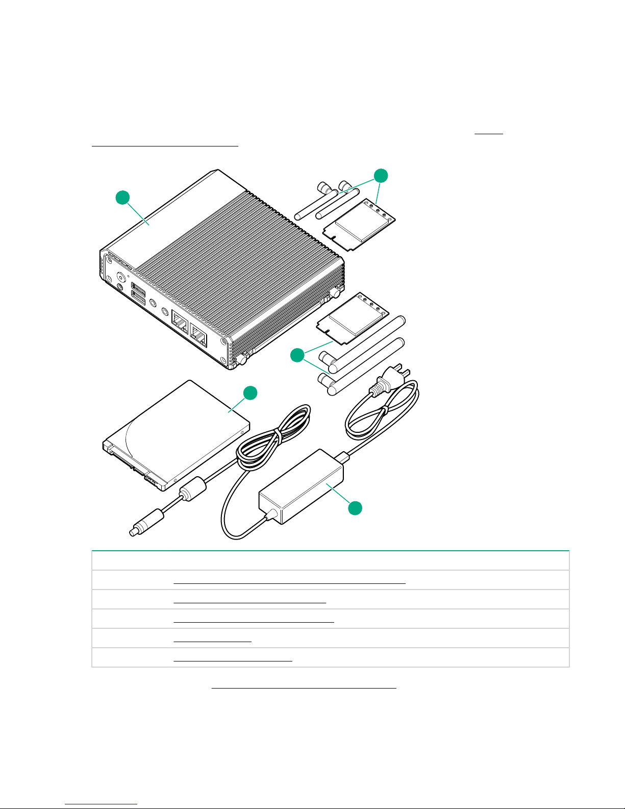
Illustrated parts catalog
1
5
2
3
4
System components
Hewlett Packard Enterprise continually improves and changes product parts. For complete and current
supported parts information, see the Hewlett Packard Enterprise PartSurfer website (
www.hpe.com/info/partssurfer).
http://
Item Description
1 EL10 Intelligent Gateway (4 GB RAM) spare part
2 3G module/antenna spare parts
3 WiFi module/antenna spare parts
4 Drive spare part
5 Power supply spare part
For more information, see Removal and replacement procedures.
Illustrated parts catalog 5
Page 6

EL10 Intelligent Gateway spare part
Customer self repair: Mandatory
Description Spare part number
EL10 Intelligent Gateway (4 GB RAM) 847063-001
3G module/antenna spare parts
Customer self repair: Mandatory
Description Spare part number
3G uPCIe Wide-Temp module Kit (includes 3G
antenna)
3G antenna GSM 850/900/1800/1900/2100 MHz
(2)
WiFi module/antenna spare parts
Customer self repair: Mandatory
Description Spare part number
WiFi 802.11 uPCIe Wide-Temp module Kit
(includes antenna)
2.4/5 GHz flexible WiFi antenna (2) 847056-001
Drive spare part
Customer self repair: Mandatory
Description Spare part number
32 GB, 2.5 inch SSD 847058-001
Power supply spare part
847057-001
871309-001
847054-001
Customer self repair: Mandatory
Description Spare part number
EL10 power supply with cord 847061-001
6 EL10 Intelligent Gateway spare part
Page 7

Customer self repair
Hewlett Packard Enterprise products are designed with many Customer Self Repair (CSR) parts to
minimize repair time and allow for greater flexibility in performing defective parts replacement. If during
the diagnosis period Hewlett Packard Enterprise (or Hewlett Packard Enterprise service providers or
service partners) identifies that the repair can be accomplished by the use of a CSR part, Hewlett
Packard Enterprise will ship that part directly to you for replacement. There are two categories of CSR
parts:
• Mandatory—Parts for which customer self repair is mandatory. If you request Hewlett Packard
Enterprise to replace these parts, you will be charged for the travel and labor costs of this service.
• Optional—Parts for which customer self repair is optional. These parts are also designed for customer
self repair. If, however, you require that Hewlett Packard Enterprise replace them for you, there may or
may not be additional charges, depending on the type of warranty service designated for your product.
NOTE: Some Hewlett Packard Enterprise parts are not designed for customer self repair. In order to
satisfy the customer warranty, Hewlett Packard Enterprise requires that an authorized service
provider replace the part. These parts are identified as "No" in the Illustrated Parts Catalog.
Based on availability and where geography permits, CSR parts will be shipped for next business day
delivery. Same day or four-hour delivery may be offered at an additional charge where geography
permits. If assistance is required, you can call the Hewlett Packard Enterprise Support Center and a
technician will help you over the telephone. Hewlett Packard Enterprise specifies in the materials shipped
with a replacement CSR part whether a defective part must be returned to Hewlett Packard Enterprise. In
cases where it is required to return the defective part to Hewlett Packard Enterprise, you must ship the
defective part back to Hewlett Packard Enterprise within a defined period of time, normally five (5)
business days. The defective part must be returned with the associated documentation in the provided
shipping material. Failure to return the defective part may result in Hewlett Packard Enterprise billing you
for the replacement. With a customer self repair, Hewlett Packard Enterprise will pay all shipping and part
return costs and determine the courier/carrier to be used.
For more information about the Hewlett Packard Enterprise CSR program, contact your local service
provider. For the North American program, go to the Hewlett Packard Enterprise CSR website
Parts only warranty service
Your Hewlett Packard Enterprise Limited Warranty may include a parts only warranty service. Under the
terms of parts only warranty service, Hewlett Packard Enterprise will provide replacement parts free of
charge.
For parts only warranty service, CSR part replacement is mandatory. If you request Hewlett Packard
Enterprise to replace these parts, you will be charged for the travel and labor costs of this service.
Réparation par le client (CSR)
Les produits Hewlett Packard Enterprise comportent de nombreuses pièces CSR (Customer Self Repair
= réparation par le client) afin de minimiser les délais de réparation et faciliter le remplacement des
pièces défectueuses. Si pendant la période de diagnostic, Hewlett Packard Enterprise (ou ses
partenaires ou mainteneurs agréés) détermine que la réparation peut être effectuée à l'aide d'une pièce
CSR, Hewlett Packard Enterprise vous l'envoie directement. Il existe deux catégories de pièces CSR :
• Obligatoire—Pièces pour lesquelles la réparation par le client est obligatoire. Si vous demandez à
Hewlett Packard Enterprise de remplacer ces pièces, les coûts de déplacement et main d'œuvre du
service vous seront facturés.
• Facultatif—Pièces pour lesquelles la réparation par le client est facultative. Ces pièces sont
également conçues pour permettre au client d'effectuer lui-même la réparation. Toutefois, si vous
Customer self repair 7
Page 8

demandez à Hewlett Packard Enterprise de remplacer ces pièces, l'intervention peut ou non vous être
facturée, selon le type de garantie applicable à votre produit.
REMARQUE: Certaines pièces Hewlett Packard Enterprise ne sont pas conçues pour permettre au client
d'effectuer lui-même la réparation. Pour que la garantie puisse s'appliquer, Hewlett Packard Enterprise
exige que le remplacement de la pièce soit effectué par un Mainteneur Agréé. Ces pièces sont identifiées
par la mention "Non" dans le Catalogue illustré.
Les pièces CSR sont livrées le jour ouvré suivant, dans la limite des stocks disponibles et selon votre
situation géographique. Si votre situation géographique le permet et que vous demandez une livraison le
jour même ou dans les 4 heures, celle-ci vous sera facturée. Pour toute assistance, appelez le Centre
d’assistance Hewlett Packard Enterprise pour qu’un technicien vous aide au téléphone Dans les
documents envoyés avec la pièce de rechange CSR, Hewlett Packard Enterprise précise s'il est
nécessaire de lui retourner la pièce défectueuse. Si c'est le cas, vous devez le faire dans le délai indiqué,
généralement cinq (5) jours ouvrés. La pièce et sa documentation doivent être retournées dans
l'emballage fourni. Si vous ne retournez pas la pièce défectueuse, Hewlett Packard Enterprise se réserve
le droit de vous facturer les coûts de remplacement. Dans le cas d'une pièce CSR, Hewlett Packard
Enterprise supporte l'ensemble des frais d'expédition et de retour, et détermine la société de courses ou
le transporteur à utiliser.
Pour plus d'informations sur le programme CSR de Hewlett Packard Enterprise, contactez votre
Mainteneur Agrée local. Pour plus d'informations sur ce programme en Amérique du Nord, consultez le
site Web Hewlett Packard Enterprise.
Service de garantie "pièces seules"
Votre garantie limitée Hewlett Packard Enterprise peut inclure un service de garantie "pièces seules".
Dans ce cas, les pièces de rechange fournies par Hewlett Packard Enterprise ne sont pas facturées.
Dans le cadre de ce service, la réparation des pièces CSR par le client est obligatoire. Si vous demandez
à Hewlett Packard Enterprise de remplacer ces pièces, les coûts de déplacement et main d'œuvre du
service vous seront facturés.
Riparazione da parte del cliente
Per abbreviare i tempi di riparazione e garantire una maggiore flessibilità nella sostituzione di parti
difettose, i prodotti Hewlett Packard Enterprise sono realizzati con numerosi componenti che possono
essere riparati direttamente dal cliente (CSR, Customer Self Repair). Se in fase di diagnostica Hewlett
Packard Enterprise (o un centro di servizi o di assistenza Hewlett Packard Enterprise) identifica il guasto
come riparabile mediante un ricambio CSR, Hewlett Packard Enterprise lo spedirà direttamente al cliente
per la sostituzione. Vi sono due categorie di parti CSR:
• Obbligatorie—Parti che devono essere necessariamente riparate dal cliente. Se il cliente ne affida la
riparazione ad Hewlett Packard Enterprise, deve sostenere le spese di spedizione e di manodopera
per il servizio.
• Opzionali—Parti la cui riparazione da parte del cliente è facoltativa. Si tratta comunque di componenti
progettati per questo scopo. Se tuttavia il cliente ne richiede la sostituzione ad Hewlett Packard
Enterprise, potrebbe dover sostenere spese addizionali a seconda del tipo di garanzia previsto per il
prodotto.
NOTA: alcuni componenti Hewlett Packard Enterprise non sono progettati per la riparazione da parte del
cliente. Per rispettare la garanzia, Hewlett Packard Enterprise richiede che queste parti siano sostituite da
un centro di assistenza autorizzato. Tali parti sono identificate da un "No" nel Catalogo illustrato dei
componenti.
In base alla disponibilità e alla località geografica, le parti CSR vengono spedite con consegna entro il
giorno lavorativo seguente. La consegna nel giorno stesso o entro quattro ore è offerta con un
supplemento di costo solo in alcune zone. In caso di necessità si può richiedere l'assistenza telefonica di
un addetto del centro di supporto tecnico Hewlett Packard Enterprise. Nel materiale fornito con una parte
di ricambio CSR, Hewlett Packard Enterprise specifica se il cliente deve restituire dei component. Qualora
sia richiesta la resa ad Hewlett Packard Enterprise del componente difettoso, lo si deve spedire ad
8 Customer self repair
Page 9

Hewlett Packard Enterprise entro un determinato periodo di tempo, generalmente cinque (5) giorni
lavorativi. Il componente difettoso deve essere restituito con la documentazione associata nell'imballo di
spedizione fornito. La mancata restituzione del componente può comportare la fatturazione del ricambio
da parte di Hewlett Packard Enterprise. Nel caso di riparazione da parte del cliente, Hewlett Packard
Enterprise sostiene tutte le spese di spedizione e resa e sceglie il corriere/vettore da utilizzare.
Per ulteriori informazioni sul programma CSR di Hewlett Packard Enterprise, contattare il centro di
assistenza di zona. Per il programma in Nord America fare riferimento al sito Web.
Servizio di garanzia per i soli componenti
La garanzia limitata Hewlett Packard Enterprise può includere un servizio di garanzia per i soli
componenti. Nei termini di garanzia del servizio per i soli componenti, Hewlett Packard Enterprise fornirà
gratuitamente le parti di ricambio.
Per il servizio di garanzia per i soli componenti è obbligatoria la formula CSR che prevede la riparazione
da parte del cliente. Se il cliente invece richiede la sostituzione ad Hewlett Packard Enterprise dovrà
sostenere le spese di spedizione e di manodopera per il servizio.
Customer Self Repair
Hewlett Packard Enterprise Produkte enthalten viele CSR-Teile (Customer Self Repair), um
Reparaturzeiten zu minimieren und höhere Flexibilität beim Austausch defekter Bauteile zu ermöglichen.
Wenn Hewlett Packard Enterprise (oder ein Hewlett Packard Enterprise Servicepartner) bei der Diagnose
feststellt, dass das Produkt mithilfe eines CSR-Teils repariert werden kann, sendet Ihnen Hewlett Packard
Enterprise dieses Bauteil zum Austausch direkt zu. CSR-Teile werden in zwei Kategorien unterteilt:
• Zwingend—Teile, für die das Customer Self Repair-Verfahren zwingend vorgegeben ist. Wenn Sie
den Austausch dieser Teile von Hewlett Packard Enterprise vornehmen lassen, werden Ihnen die
Anfahrt- und Arbeitskosten für diesen Service berechnet.
• Optional—Teile, für die das Customer Self Repair-Verfahren optional ist. Diese Teile sind auch für
Customer Self Repair ausgelegt. Wenn Sie jedoch den Austausch dieser Teile von Hewlett Packard
Enterprise vornehmen lassen möchten, können bei diesem Service je nach den für Ihr Produkt
vorgesehenen Garantiebedingungen zusätzliche Kosten anfallen.
HINWEIS: Einige Hewlett Packard Enterprise Teile sind nicht für Customer Self Repair ausgelegt. Um den
Garantieanspruch des Kunden zu erfüllen, muss das Teil von einem Hewlett Packard Enterprise
Servicepartner ersetzt werden. Im illustrierten Teilekatalog sind diese Teile mit „No“ bzw.
„Nein“ gekennzeichnet.
CSR-Teile werden abhängig von der Verfügbarkeit und vom Lieferziel am folgenden Geschäftstag
geliefert. Für bestimmte Standorte ist eine Lieferung am selben Tag oder innerhalb von vier Stunden
gegen einen Aufpreis verfügbar. Wenn Sie Hilfe benötigen, können Sie das Hewlett Packard Enterprise
Support Center anrufen und sich von einem Mitarbeiter per Telefon helfen lassen. Den Materialien von
Hewlett Packard Enterprise, die mit einem CSR-Ersatzteil geliefert werden, können Sie entnehmen, ob
das defekte Teil an Hewlett Packard Enterprise zurückgeschickt werden muss. Wenn es erforderlich ist,
das defekte Teil an Hewlett Packard Enterprise zurückzuschicken, müssen Sie dies innerhalb eines
vorgegebenen Zeitraums tun, in der Regel innerhalb von fünf (5) Geschäftstagen. Das defekte Teil muss
mit der zugehörigen Dokumentation in der Verpackung zurückgeschickt werden, die im Lieferumfang
enthalten ist. Wenn Sie das defekte Teil nicht zurückschicken, kann Hewlett Packard Enterprise Ihnen das
Ersatzteil in Rechnung stellen. Im Falle von Customer Self Repair kommt Hewlett Packard Enterprise für
alle Kosten für die Lieferung und Rücksendung auf und bestimmt den Kurier-/Frachtdienst.
Weitere Informationen über das Hewlett Packard Enterprise Customer Self Repair Programm erhalten Sie
von Ihrem Servicepartner vor Ort. Informationen über das CSR-Programm in Nordamerika finden Sie auf
der Hewlett Packard Enterprise Website unter.
Customer self repair 9
Page 10

Parts-only Warranty Service (Garantieservice ausschließlich für Teile)
Ihre Hewlett Packard Enterprise Garantie umfasst möglicherweise einen Parts-only Warranty Service
(Garantieservice ausschließlich für Teile). Gemäß den Bestimmungen des Parts-only Warranty Service
stellt Hewlett Packard Enterprise Ersatzteile kostenlos zur Verfügung.
Für den Parts-only Warranty Service ist das CSR-Verfahren zwingend vorgegeben. Wenn Sie den
Austausch dieser Teile von Hewlett Packard Enterprise vornehmen lassen, werden Ihnen die Anfahrt- und
Arbeitskosten für diesen Service berechnet.
Reparaciones del propio cliente
Los productos de Hewlett Packard Enterprise incluyen muchos componentes que el propio usuario puede
reemplazar (Customer Self Repair, CSR) para minimizar el tiempo de reparación y ofrecer una mayor
flexibilidad a la hora de realizar sustituciones de componentes defectuosos. Si, durante la fase de
diagnóstico, Hewlett Packard Enterprise (o los proveedores o socios de servicio de Hewlett Packard
Enterprise) identifica que una reparación puede llevarse a cabo mediante el uso de un componente CSR,
Hewlett Packard Enterprise le enviará dicho componente directamente para que realice su sustitución.
Los componentes CSR se clasifican en dos categorías:
• Obligatorio—Componentes cuya reparación por parte del usuario es obligatoria. Si solicita a Hewlett
Packard Enterprise que realice la sustitución de estos componentes, tendrá que hacerse cargo de los
gastos de desplazamiento y de mano de obra de dicho servicio.
• Opcional—Componentes cuya reparación por parte del usuario es opcional. Estos componentes
también están diseñados para que puedan ser reparados por el usuario. Sin embargo, si precisa que
Hewlett Packard Enterprise realice su sustitución, puede o no conllevar costes adicionales,
dependiendo del tipo de servicio de garantía correspondiente al producto.
NOTA: Algunos componentes de Hewlett Packard Enterprise no están diseñados para que puedan ser
reparados por el usuario. Para que el usuario haga valer su garantía, Hewlett Packard Enterprise pone
como condición que un proveedor de servicios autorizado realice la sustitución de estos componentes.
Dichos componentes se identifican con la palabra "No" en el catálogo ilustrado de componentes.
Según la disponibilidad y la situación geográfica, los componentes CSR se enviarán para que lleguen a
su destino al siguiente día laborable. Si la situación geográfica lo permite, se puede solicitar la entrega en
el mismo día o en cuatro horas con un coste adicional. Si precisa asistencia técnica, puede llamar al
Centro de asistencia técnica de Hewlett Packard Enterprise y recibirá ayuda telefónica por parte de un
técnico. Con el envío de materiales para la sustitución de componentes CSR, Hewlett Packard Enterprise
especificará si los componentes defectuosos deberán devolverse a Hewlett Packard Enterprise. En
aquellos casos en los que sea necesario devolver algún componente a Hewlett Packard Enterprise,
deberá hacerlo en el periodo de tiempo especificado, normalmente cinco días laborables. Los
componentes defectuosos deberán devolverse con toda la documentación relacionada y con el embalaje
de envío. Si no enviara el componente defectuoso requerido, Hewlett Packard Enterprise podrá cobrarle
por el de sustitución. En el caso de todas sustituciones que lleve a cabo el cliente, Hewlett Packard
Enterprise se hará cargo de todos los gastos de envío y devolución de componentes y escogerá la
empresa de transporte que se utilice para dicho servicio.
Para obtener más información acerca del programa de Reparaciones del propio cliente de Hewlett
Packard Enterprise, póngase en contacto con su proveedor de servicios local. Si está interesado en el
programa para Norteamérica, visite la página web de Hewlett Packard Enterprise CSR.
Servicio de garantía exclusivo de componentes
La garantía limitada de Hewlett Packard Enterprise puede que incluya un servicio de garantía exclusivo
de componentes. Según las condiciones de este servicio exclusivo de componentes, Hewlett Packard
Enterprise le facilitará los componentes de repuesto sin cargo adicional alguno.
Para este servicio de garantía exclusivo de componentes, es obligatoria la sustitución de componentes
por parte del usuario (CSR). Si solicita a Hewlett Packard Enterprise que realice la sustitución de estos
componentes, tendrá que hacerse cargo de los gastos de desplazamiento y de mano de obra de dicho
servicio.
10 Customer self repair
Page 11

Customer Self Repair
Veel onderdelen in Hewlett Packard Enterprise producten zijn door de klant zelf te repareren, waardoor
de reparatieduur tot een minimum beperkt kan blijven en de flexibiliteit in het vervangen van defecte
onderdelen groter is. Deze onderdelen worden CSR-onderdelen (Customer Self Repair) genoemd. Als
Hewlett Packard Enterprise (of een Hewlett Packard Enterprise Service Partner) bij de diagnose vaststelt
dat de reparatie kan worden uitgevoerd met een CSR-onderdeel, verzendt Hewlett Packard Enterprise
dat onderdeel rechtstreeks naar u, zodat u het defecte onderdeel daarmee kunt vervangen. Er zijn twee
categorieën CSR-onderdelen:
• Verplicht—Onderdelen waarvoor reparatie door de klant verplicht is. Als u Hewlett Packard Enterprise
verzoekt deze onderdelen voor u te vervangen, worden u voor deze service reiskosten en arbeidsloon
in rekening gebracht.
• Optioneel—Onderdelen waarvoor reparatie door de klant optioneel is. Ook deze onderdelen zijn
ontworpen voor reparatie door de klant. Als u echter Hewlett Packard Enterprise verzoekt deze
onderdelen voor u te vervangen, kunnen daarvoor extra kosten in rekening worden gebracht,
afhankelijk van het type garantieservice voor het product.
OPMERKING: Sommige Hewlett Packard Enterprise onderdelen zijn niet ontwikkeld voor reparatie door
de klant. In verband met de garantievoorwaarden moet het onderdeel door een geautoriseerde Service
Partner worden vervangen. Deze onderdelen worden in de geïllustreerde onderdelencatalogus
aangemerkt met "Nee".
Afhankelijk van de leverbaarheid en de locatie worden CSR-onderdelen verzonden voor levering op de
eerstvolgende werkdag. Levering op dezelfde dag of binnen vier uur kan tegen meerkosten worden
aangeboden, indien dit mogelijk is gezien de locatie. Indien assistentie is gewenst, belt u het Hewlett
Packard Enterprise Support Center om via de telefoon ondersteuning van een technicus te ontvangen.
Hewlett Packard Enterprise vermeldt in de documentatie bij het vervangende CSR-onderdeel of het
defecte onderdeel aan Hewlett Packard Enterprise moet worden geretourneerd. Als het defecte
onderdeel aan Hewlett Packard Enterprise moet worden teruggezonden, moet u het defecte onderdeel
binnen een bepaalde periode, gewoonlijk vijf (5) werkdagen, retourneren aan Hewlett Packard Enterprise.
Het defecte onderdeel moet met de bijbehorende documentatie worden geretourneerd in het
meegeleverde verpakkingsmateriaal. Als u het defecte onderdeel niet terugzendt, kan Hewlett Packard
Enterprise u voor het vervangende onderdeel kosten in rekening brengen. Bij reparatie door de klant
betaalt Hewlett Packard Enterprise alle verzendkosten voor het vervangende en geretourneerde
onderdeel en kiest Hewlett Packard Enterprise zelf welke koerier/transportonderneming hiervoor wordt
gebruikt.
Neem contact op met een Service Partner voor meer informatie over het Customer Self Repair
programma van Hewlett Packard Enterprise. Informatie over Service Partners vindt u op de Hewlett
Packard Enterprise website.
Garantieservice "Parts Only"
Het is mogelijk dat de Hewlett Packard Enterprise garantie alleen de garantieservice "Parts Only" omvat.
Volgens de bepalingen van de Parts Only garantieservice zal Hewlett Packard Enterprise kosteloos
vervangende onderdelen ter beschikking stellen.
Voor de Parts Only garantieservice is vervanging door CSR-onderdelen verplicht. Als u Hewlett Packard
Enterprise verzoekt deze onderdelen voor u te vervangen, worden u voor deze service reiskosten en
arbeidsloon in rekening gebracht
Reparo feito pelo cliente
Os produtos da Hewlett Packard Enterprise são projetados com muitas peças para reparo feito pelo
cliente (CSR) de modo a minimizar o tempo de reparo e permitir maior flexibilidade na substituição de
peças com defeito. Se, durante o período de diagnóstico, a Hewlett Packard Enterprise (ou fornecedores/
parceiros da Hewlett Packard Enterprise) concluir que o reparo pode ser efetuado pelo uso de uma peça
CSR, a Hewlett Packard Enterprise enviará a peça diretamente ao cliente. Há duas categorias de peças
CSR:
Customer self repair 11
Page 12

• Obrigatória—Peças cujo reparo feito pelo cliente é obrigatório. Se desejar que a Hewlett Packard
Enterprise substitua essas peças, serão cobradas as despesas de transporte e mão-de-obra do
serviço.
• Opcional—Peças cujo reparo feito pelo cliente é opcional. Essas peças também são projetadas para
o reparo feito pelo cliente. No entanto, se desejar que a Hewlett Packard Enterprise as substitua,
pode haver ou não a cobrança de taxa adicional, dependendo do tipo de serviço de garantia
destinado ao produto.
OBSERVAÇÃO: Algumas peças da Hewlett Packard Enterprise não são projetadas para o reparo feito
pelo cliente. A fim de cumprir a garantia do cliente, a Hewlett Packard Enterprise exige que um técnico
autorizado substitua a peça. Essas peças estão identificadas com a marca "No" (Não), no catálogo de
peças ilustrado.
Conforme a disponibilidade e o local geográfico, as peças CSR serão enviadas no primeiro dia útil após
o pedido. Onde as condições geográficas permitirem, a entrega no mesmo dia ou em quatro horas pode
ser feita mediante uma taxa adicional. Se precisar de auxílio, entre em contato com o Centro de suporte
técnico da Hewlett Packard Enterprise para que um técnico o ajude por telefone. A Hewlett Packard
Enterprise especifica nos materiais fornecidos com a peça CSR de reposição se a peça com defeito deve
ser devolvida à Hewlett Packard Enterprise. Nos casos em que isso for necessário, é preciso enviar a
peça com defeito à Hewlett Packard Enterprise, você deverá enviar a peça com defeito de volta para a
Hewlett Packard Enterprise dentro do período de tempo definido, normalmente em 5 (cinco) dias úteis. A
peça com defeito deve ser enviada com a documentação correspondente no material de transporte
fornecido. Caso não o faça, a Hewlett Packard Enterprise poderá cobrar a reposição. Para as peças de
reparo feito pelo cliente, a Hewlett Packard Enterprise paga todas as despesas de transporte e de
devolução da peça e determina a transportadora/serviço postal a ser utilizado.
Para obter mais informações sobre o programa de reparo feito pelo cliente da Hewlett Packard
Enterprise, entre em contato com o fornecedor de serviços local. Para o programa norte-americano,
visite o site da Hewlett Packard Enterprise.
Serviço de garantia apenas para peças
A garantia limitada da Hewlett Packard Enterprise pode incluir um serviço de garantia apenas para
peças. Segundo os termos do serviço de garantia apenas para peças, a Hewlett Packard Enterprise
fornece as peças de reposição sem cobrar nenhuma taxa.
No caso desse serviço, a substituição de peças CSR é obrigatória. Se desejar que a Hewlett Packard
Enterprise substitua essas peças, serão cobradas as despesas de transporte e mão-de-obra do serviço.
12 Customer self repair
Page 13
Customer self repair 13
Page 14
14 Customer self repair
Page 15

Customer self repair 15
Page 16

Removal and replacement procedures
Required tools
You need the following items for some procedures:
• T-10 Torx screwdriver
• M3.5 (3.5 mm) flathead screwdriver
• M3 (3 mm) Phillips screwdriver
Safety considerations
Before performing service procedures, review all the safety information.
Preventing electrostatic discharge
To prevent damaging the system, be aware of the precautions you must follow when setting up the
system or handling parts. A discharge of static electricity from a finger or other conductor may damage
system boards or other static-sensitive devices. This type of damage may reduce the life expectancy of
the device.
Procedure
• Avoid hand contact by transporting and storing products in static-safe containers.
• Keep electrostatic-sensitive parts in their containers until they arrive at static-free workstations.
• Place parts on a grounded surface before removing them from their containers.
• Avoid touching pins, leads, or circuitry.
• Always be properly grounded when touching a static-sensitive component or assembly.
Symbols on equipment
The following symbols might be found on the equipment to indicate the presence of potentially hazardous
conditions.
This symbol indicates the presence of hazardous energy circuits or electric shock
hazards. Refer all servicing to qualified personnel.
WARNING: To reduce the risk of injury from electric shock hazards, do not open this
enclosure. Refer all maintenance, upgrades, and servicing to qualified personnel.
This symbol indicates the presence of electric shock hazards. The area contains no
user or field serviceable parts. Do not open for any reason.
WARNING: To reduce the risk of injury from electric shock hazards, do not open this
enclosure.
This symbol on an RJ-45 receptacle indicates a network interface connection.
WARNING: To reduce the risk of electric shock, fire, or damage to the equipment, do
not plug telephone or telecommunications connectors into this receptacle.
16 Removal and replacement procedures
Page 17

This symbol indicates the presence of a hot surface or hot component. If this surface is
0.68 kg
1.5 lb
contacted, the potential for injury exists.
WARNING: To reduce the risk of injury from a hot component, allow the surface to cool
before touching.
This symbol indicates that the component exceeds the recommended weight for one
individual to handle safely.
WARNING: To reduce the risk of personal injury or damage to the equipment,
observe local occupational health and safety requirements and guidelines for manual
material handling.
These symbols, on power supplies or systems, indicate that the equipment is supplied
by multiple sources of power.
WARNING: To reduce the risk of injury from electric shock, remove all power cords to
disconnect power from the system completely.
System warnings and cautions
Before installing a system, be sure that you understand the following warnings and cautions.
WARNING:
To reduce the risk of electric shock or damage to the equipment:
• Do not disable the power cord grounding plug. The grounding plug is an important safety feature.
• Plug the power cord into a grounded (earthed) electrical outlet that is easily accessible at all
times.
• Unplug the power cord from the power supply to disconnect power to the equipment.
• Do not route the power cord where it can be walked on or pinched by items placed against it.
Pay particular attention to the plug, electrical outlet, and the point where the cord extends from
the system.
WARNING:
To reduce the risk of personal injury from hot surfaces, allow the drives and the internal system
components to cool before touching them.
CAUTION:
Do not operate the system for long periods with the access panel open or removed. Operating the
system in this manner results in improper airflow and improper cooling that can lead to thermal
damage.
Preparing to remove or replace components
Before performing certain service procedures and to access some components, you must perform one or
more of the following procedures.
Procedure
1. Power down the gateway.
System warnings and cautions 17
Page 18

If you must dismount the gateway or remove a non-hot-plug component from the gateway, then you
must power down the gateway.
2. Dismount the gateway.
If the environment, cabling configuration, or the gateway location creates unstable conditions, then
dismount the gateway and place it on a stable surface.
3. Remove the bottom access panel.
Powering down the gateway
Before powering down the system for any upgrade or maintenance procedures, you must back up critical
system data and programs.
Use one of the following methods to power down the system:
• Press and release the Power On/Standby button.
This method initiates a controlled shutdown of applications and the OS before the system enters
standby mode.
• Press and hold the Power On/Standby button for more than 4 seconds to force the system to power
down.
This method forces the system to power down without properly exiting applications and the OS. If an
application stops responding, you can use this method to force a shutdown.
Before proceeding, you must ensure that the system is in standby mode by verifying that the system
power LED is off.
Dismounting the gateway
You can use one of the following dismounting methods, depending on where and how the gateway is
mounted:
• Dismounting a wall-mount gateway.
• Dismounting a rack-mount gateway.
• Dismounting a VESA-mount gateway.
Dismounting a wall-mount gateway
Procedure
1. Remove the screws securing the wall-mount brackets to the wall.
2. Remove the four M3.5 screws securing the wall-mount brackets to the gateway, and then remove the
brackets.
18 Powering down the gateway
Page 19

2
2
1
1
1
1
To replace the component, reverse the removal procedure.
3
2
2
1
3
2
2
1
Dismounting a rack-mount gateway
Procedure
1. Slide the rail mounts off the wall-mount brackets.
2. Remove the four screws securing the wall-mount brackets to the gateway, and then remove the
brackets.
To replace the component, reverse the removal procedure.
Dismounting a VESA-mount gateway
Procedure
1. Remove the four M3 Phillips screws securing the VESA-mounting brackets to the gateway.
2. Remove the top-mounting bracket.
3. Remove the four M3.5 screws securing the bottom bracket.
4. Remove the bottom bracket.
Dismounting a rack-mount gateway 19
Page 20

1
1
2
4
3
3
3
3
To replace the component, reverse the removal procedure.
Removing the bottom access panel
Procedure
1. Using a Torx head screwdriver, remove the four T-10 Torx head screws securing the access panel to
the bottom of the gateway.
2. Lift the access panel up, and then set it to the side. The jumper cables connecting the drive are still
attached.
20 Removing the bottom access panel
Page 21

Removing and replacing a drive
Procedure
1. Power down the gateway.
2. Dismount the gateway.
CAUTION:
DO NOT remove the top access panel under any circumstance. Removing the top access panel
can harm the heatsink or void the warranty to the equipment.
3. Remove the bottom access panel.
4. Disconnect the signal and power jumper cables to the drive.
5. Using a T-10 Torx screwdriver, remove the four screws securing the drive to the access panel.
6. Remove the drive.
Removing and replacing a drive 21
Page 22

7. Install the bottom cover using the four bottom cover screws.
WAN
WAN
To replace the component, reverse the removal procedure.
You must press the Power On/Off button twice to power on the system.
Removing and replacing a 3G module
Procedure
1. Power down the gateway.
2. Dismount the gateway.
CAUTION:
DO NOT remove the top access panel under any circumstance. Removing the top access panel
can harm the heatsink or void the warranty to the equipment.
3. Remove the bottom access panel.
4. Disconnect the two antenna cables from the antenna connectors on the 3G module.
22 Removing and replacing a 3G module
Page 23

5. Using a T-10 Torx screwdriver, remove the screws securing the 3G modules to the gateway.
WAN
WAN
6. Remove the module.
To replace the component, reverse the removal procedure.
You must press the Power On/Off button twice to power on the system.
Removing and replacing a WiFi module
Procedure
1. Power down the gateway.
2. Dismount the gateway.
3. Remove the bottom access panel.
CAUTION:
DO NOT remove the top access panel under any circumstance. Removing the top access panel
can harm the heatsink or void the warranty to the equipment.
4. Disconnect the two antenna cables from the antenna connectors on the WiFi module.
Removing and replacing a WiFi module 23
Page 24

WLAN
WLAN
5. Using a T-10 Torx screwdriver, remove the screws securing the WiFi module to the gateway.
WLAN
WLAN
6. Remove the WiFi module.
To replace the component, reverse the removal procedure.
You must press the Power On/Off button twice to power on the system.
Removing and replacing an antenna
Procedure
1. Power down the gateway.
2. Dismount the gateway.
3. Locate the correct antenna. The rear access label includes indication of which antenna pair is for 3G
and which antenna pair is for WiFi.
24 Removing and replacing an antenna
Page 25

WAN
WAN
WLAN
WLAN
4. Unscrew and remove the antenna from the gateway.
To replace the component, reverse the removal procedure.
You must press the Power On/Off button twice to power on the system.
Removing and replacing a power supply
Procedure
1. Power down the gateway.
2. Disconnect the power cord from the power connector at the rear of the gateway.
To replace the component, reverse the removal procedure.
You must press the Power On/Off button twice to power on the system.
Removing and replacing a power supply 25
Page 26

Component identification
Front panel components
Item Description
1 USB 2.0 connector
2 USB 3.0 connector
3 Audio in
4 Audio out
5 LAN 1 connector
6 LAN 2 connector
Front panel LEDs and buttons
26 Component identification
Page 27

Item Description Status
1 Power On/Off button LED
2 Drive LED
3 Reset button Press to reset the system
1
The reset button is indented and you might need a tool, such as a pin, to press it.
Rear panel components
• Solid green = System on
• Off = System off
• Solid or blinking white = Drive active
• Off = Drive not active
1
Item Description
1 Power connector
2 HDMI connector
3 Serial port connector (RS-232 or RS-422/485)
4 Micro HDMI connector
5 VGA connector
6 Micro USB 2.0 connector
Connector pin assignments
RJ-45 LAN connector pin assignments
Rear panel components 27
Page 28

Pin Signal name (10/100/1000 Mbps)
1 TX+, MDI0+
2 TX-, MDI0-
3 RX+, MDI1+
4 MDI2+
5 MDI2-
6 RX-, MDI1-
7 MDI3+
8 MDI3-
1
NC, if present, means that there is no connection.
HDMI connector pin assignments
The HDMI link supports resolutions of up to 1920 x 1080 at 60 Hz. However, the HDMI link does not
support hot-plug function.
1
Pin Assignment
1 TMDS_Data2+/DP_Data0+
2 GND
3 TMDS_Data2-/DP_Data0-
4 TMDS_Data1+/DP_Data1+
5 GND
6 TMDS_Data1-/DP_Data1-
7 TMDS_Data0+/DP_Data2+
8 GND
9 TMDS_Data0-/DP_Data2-
10 TMDS_Clock+/DP_Data3+
11 GND
12 TMDS_Clock-/DP_Data3-
13 NC
14 NC
Table Continued
28 HDMI connector pin assignments
Page 29

Pin Assignment
15 SCL/AUX_CH+
16 SDA/GND
17 DDC GND/AUX_CH-
18 +5 V/Hot-plug detect
19 Hot-plug detect return
20 DP_PWR
I/O serial port 1 pin assignments
Pin Assignment
1 Not connected
2 Not connected
3 Not connected
4 RTS
5 TXD
6 CTS
7 Not connected
8 Optional 5 V/12 V power
9 Ground
10 Not connected
I/O serial port 1 pin assignments 29
Page 30

I/O serial port 2 pin assignments
Pin Assignment
1 Ground
2 CTS-
3 CTS+-
4 RTS-
5 RTS+
6 TXD+
7 RXD+
8 TXD-
9 RXD-
10 Not connected
DB9 connector pin assignments for RS422/485
After setting the I/O serial port from serial port 1 to serial port 2, the port supports four-wire RS422/485
signals in half-duplex mode. The DB9 connectors then have the following pin assignments.
Pin Assignment
1 Ground
2 CTS+ (HSI+)
30 I/O serial port 2 pin assignments
Table Continued
Page 31

Pin Assignment
3 RTS+ (HSO+)
4 RXD+
5 RXD-
6 CTS- (HSI-)
7 RTS- (HSO-)
8 TXD+
9 TXD-
RS485-solar sensor pin assignments
Pin RS485 pin assignment Solar sensor pin assignment
Orange Data-/B CAN high
Brown Data+/A CAN low
Black Supply (negative) Supply (negative)
Red Supply (positive) Supply (positive)
Black (thick) Shield Shield
Gateway-solar sensor connector pin assignments
Pin Gateway pin assignment RS485 pin assignment RS485 pin color
4 RXD+ Data+/A Brown
5 RXD- Data-/B Orange
8 TXD+ Data+/A Brown
9 TXD- Data-/B Orange
SATA LED connector pin assignments
RS485-solar sensor pin assignments 31
Page 32

Pin Assignment
1 LED+
2 LED-
VGA D-SUB connector pin assignments
Pin Assignment
1 Red
2 DDC clock
3 Green
4 Ground
5 Blue
6 DDC data
7 V Sync
8 Ground
9 H Sync
32 VGA D-SUB connector pin assignments
Page 33

Troubleshooting
Supported operating systems and drivers matrix
The following operating systems are supported.
Operating system Device driver required
Windows Server R2 2012 Yes
Windows 7 x64 (non-IoT) Yes
Windows 8.1 x64 (non-IoT) Yes
Windows 10 x64 (non-IoT) Yes
CentOS 6.7 No
CentOS 7.2 No
For more information about operating systems, see the product QuickSpecs on the Hewlett Packard
Enterprise website (http://www.hpe.com/info/qs).
You can download the latest device drivers from the Hewlett Packard Enterprise Support Center website
(http://www.hpe.com/support/hpesc).
System BIOS
Using the system BIOS to configure system and troubleshoot issues
The system can be set up and configured through the system BIOS. The system BIOS also has options
for restoring default configurations and resetting the system. The setup information is stored in the
battery-backed CMOS, therefore it retains the setup information even when the power is turned off.
For more information, see "Setting up the system BIOS."
Accessing the system BIOS
Procedure
1. Connect KVM to the system.
2. Power up the system.
3. Press the Delete key or the F2 key.
The BIOS Main tab is displayed.
Setting up the system BIOS
BIOS menu components
The BIOS menu has the following frames:
• Left frame—Displays the sub menu. Only the sub-menu options in blue can be modified. When an
option is selected in the left frame, it is highlighted in white.
• Top right frame—Displays information about the sub-menu option selected.
• Bottom right frame—Displays the keys to use to make changes to the selected sub menu.
Troubleshooting 33
Page 34

Navigating and modifying menu options
Procedure
1. Access the system BIOS.
2. Press the right arrow key to navigate to the tab to modify.
3. Press the up and down arrow keys to navigate to the sub-menu options on the left frame.
4. When you reach a sub-menu option to modify, press the Enter key.
5. Press the + key or the - key to modify the setting selected.
6. Do one of the following:
• Press the F4 key to save the new setting and exit.
• Press the Esc key to exit without saving.
Main tab
The Main tab displays general BIOS information including the following menu options:
• System Date
• System Time
Setting the System Date and System Time
Procedure
1. Access the system BIOS Main tab.
2. Press the up and down arrow keys to navigate to the sub-menu options on the left frame.
3. When you reach a sub-menu option to modify, press the Enter key.
4. Press the Tab key or the arrow keys to navigate the fields.
5. Enter the new values.
The date must be entered in the MM/DD/YY format. The time must be entered in the HH:MM:SS
format.
6. Do one of the following:
• Press the F4 key to save the new values and exit.
• Press the Esc key to exit without saving.
34 Navigating and modifying menu options
Page 35

Advanced tab
The Advanced tab includes the following menu options:
• Trusted Computing
• Intel (R) Smart Connect Technology
• CPU Configuration
• PPM Configuration
• IDE Configuration
• Miscellaneous Configuration
• CSM Configuration
• USB Configuration
• Security Configuration
Trusted Computing
General status and security configuration settings are displayed, including:
• Security Device Support—Enables or disables Security Device Support
• TPM State—Enables or disables TPM State
• TPM Enabled Status—Displays whether TPM is enabled or disabled
• TPM Active Status—Displays whether TPM is active or inactive
ACPI Settings
• Enable ACPI Auto Configuration—Enables or disables the BIOS ACPI auto configuration
• Enable Hibernation—Enables or disables system hibernation (OS/S4 sleep state) settings. This
option may not be effective with some operating systems.
Advanced tab 35
Page 36

• ACPI Sleep State—Selects the highest ACPI sleep state the system will enter when the SUSPEND
button is pressed
• Lock Legacy Resources—Enables or disables lock legacy device resources
Intel (R) Smart Connect Technology
• ISCT Support—Enables or disables BIOS ISCT support
CPU Configuration
Displays general CPU configuration values, including socket CPU information
PPM Configuration
• CPU C-state Report—Enables or disables CPU C-state report to OS
• Max CPU C-state—Enables user to control the Max C-state that the processor will support
• S0ix—Enables or disables CPU S0ix state
IDE Configuration
• Serial-ATA (SATA)—Enables or disables Serial ATA. The internal disk might not be usable if this
option is disabled.
• SATA Speed Support—Displays whether SATA Speed Support is Gen1 or Gen2
• SATA ODD Port—Displays whether SATA ODD is Port1 or No ODD
• SATA Mode—Enables user to select IDE or AHCI modes
• mSATA—Enables or disables mSATA function. If mSATA is not installed, this function is disabled.
• Serial-ATA Port 1—Enables or disables Serial ATA Port
• SATA port2 HotPlug—Enables or disables Serial ATA Port 2 hot-plug function
Miscellaneous Configuration
• High Precision Timer—Enables or disables the High Precision Event Timer
• PCI Express Dynamic Clock Gating—Enables user to adjust PCI express clock
• OS selection—Enables user to select OS: Windows 8.X/Windows 7/Android
CSM Configuration
• CSM Support—Enables or disables CSM support
• GateA20 Active:
◦ UPON REQUEST—GA20 can be disabled using BIOS services.
◦ ALWAYS—Do not allow disabling GA20. This option is useful when any RT code is executed above
1 MB.
• Option ROM Messages—Enables user to set display mode for Option ROM to Force BIOS or Keep
Current
NOTE: The system default is UEFI and Legacy, which can support all operating systems.
However, if you are using Secure Boot Mode, select UEFI Only.
• Boot option filter—Enables user to control Legacy/UEFI ROMs priority
• Storage—Enables user to control the execution of UEFI and Legacy Storage Option ROM
• Video—Enables user to control the execution of UEFI and Legacy Video Option ROM
• Other PCI devices—Enables user to set Option ROM execution policy for devices other than
Network, Storage, or Video
36 Intel (R) Smart Connect Technology
Page 37

USB Configuration
• Legacy USB Support—Enables user to set support for legacy USB. Auto option disables legacy
support if no USB devices are connected.
• XHCI Hand-off—Offers user a workaround for the OS without XHCI hand-off support. The XHCI
ownership change should be claimed by the XHCI driver.
• EHCI Hand-off—Offers user a workaround for the OS without EHCI hand-off support. The EHCI
ownership change should be claimed by the EHCI driver.
• USB Mass Storage Driver Support—Enables or disables mass storage support
• USB transfer time out—Enables user to set the time-out value for control, bulk, and interrupt
transfers
• Device reset time out—Enables user to set the USB mass storage device start unit command timeout value
• Device power up delay—Enables user to set the maximum time the device will take before it properly
reports itself to the Host Controller. 'Auto' uses default value: for a Root port it is 100 ms: for a Hub
port the delay is taken from Hub descriptor.
Security Configuration
• TXE—Enables or disables TXE
• TXE HMRFPO—Enables or disables TXE HMRFPO
• TXE Firmware Update—Enables or disables automatic firmware updates for TXE
• TXE EOP Message—Enables or disables TXE to send an EOP Message before entering
• Intel (R) AT—Enables or disables BIOS AT code from running
• Intel (R) AT Platform PBA—Enables or disables BIOS AT code from running
Chipset tab
The Chipset tab displays general configuration details including the following menu options:
• North Bridge—Details of North Bridge parameters
• South Bridge—Details of South Bridge parameters
North Bridge sub-menu options
• Intel IGD Configuration—Enables user to configure Intel IGD settings
• Graphics Power Management Control—Enables user to set graphics power management control
options
USB Configuration 37
Page 38

• LCD Control—Enables user to set LCD control
• Memory Information—Displays memory frequency and timing setting information
• Max TOLUD—Displays the maximum value of TOLUD
Intel IGD Configuration
• GOP Configuration—Displays GOP driver option
• GOP Driver—Enables GOP driver to unload VBIOS. Disable GOP driver to load BIOS.
• Integrated Graphics Device—Enables or disables Intel IGD. Enable when selected as the Primary
Video Adapter.
• IGD Turbo Enable—Enables or disables IGD turbo function
• Primary Display—Enables user to select which IGD/PCI graphics device should be the primary
display
• GFX Boost—Enables or disables GFX boost function
• PAVC—Enables or disables PAVC
• DVMT Pre-Allocated—Enables user to select DVMT 5.0 pre-allocated (fixed) graphics memory size
used by the IGD
• DVMT Total Gfx Mem—Enables user to select DVMT 5.0 total graphic memory size used by the IGD
• Aperture Size—Enables user to select the aperture size
• DOP CG—Enables or disables DOP clock gating
• GTT Size—Enables user to select the GTT size
• IGD Thermal—Enables or disables IGD thermal
• Spread Spectrum clock—Enables or disables spread spectrum clock
• ISP Enable/Disable—Enables or disables ISP PCI device selection
• ISP PCI Device Selection—Enables user to select ISP PCI. Default ISP is PCI B0D2F0 for Windows
Boot. Perform Linux Boot to select B0D3G0.
• VCC_Vnn for Power State2—Enables or disables VCC_Vnn power state2
Graphics Power Management Control
RC6 (Render Standby)—Enables or disables render standby support
LCD Control
• Primary IGFX Boot Display—Enables user to select the video device that will be activated during
POST. VGA mode is only supported on primary display.
• LVDS Panel Type—Enables and selects LCDS type or disables LVDS function
South Bridge sub-menu options
• Azalia HD Audio —Displays Azalia HD audio options
• USB Configuration —Displays USB configuration settings
• PCI Express Configuration —Displays PCI Express configuration settings
• LPSS and SCC Devices Mode—Displays LPSS and SCC device mode settings
• LAN1 Control—Enables or disables LAN1
◦ LAN1 PXE Option ROM—Enables or disables boot option for LAN1 Controller
• LAN2 Control—Enables or disables LAN2
◦ LAN2 PXE Option ROM—Enables or disables boot option for LAN2 Controller
• Global SMI Lock—Enables or disables SMI lock
• BIOS Read/Write Protection—Enables or disables BIOS SPI region read/write protect
38 Intel IGD Configuration
Page 39

Audio Configuration
• Audio Controller—Enables or disables the detection of the Azalia device
USB Configuration
• XHCI Mode—Enables and selects the mode of operation of XHCI controller
• USB2 Link Power Management—Enables or disables USB2 Link Power Management
• USB 2.0(EHCI) Support—Enables user to control the USB EHCI (USB 2.0) functions. One EHCI
controller must always be enabled.
PCI Express Configuration
• Mini PCI Express—Enables or disables mini-PCI Express port
◦ Hot Plug—Enables or disables mini-PCIe hot-plug function
◦ Speed—Enables user to select PCIe port speed
• Extra Bus Reserved—Enables or disables extra bus reserved (0-3) for bridges behind the root bridge
• Reserved Memory—Enables user to select the amount of reserved memory
• Reserved Memory Alignment—Enables user to select the amount of reserved memory alignment
• Prefetchable Memory—Enables user to select the amount of prefetchable memory
• Prefetchable Memory Alignment—Enables user to select the amount of prefetchable memory
alignment
• Reserved I/O—Enables user to select the amount of reserved I/O
Security tab
The Security tab displays password information including the following menu options:
• Administrator Password—Enables user to set administrator password
• User Password—Enables user to set user password
• Secure Boot
• Secure Flash Update—Enables user to update secure flash
Secure Boot
• Secure Boot—Enables or disables secure boot function
• Secure Boot Mode—Enables user to select secure boot mode
Audio Configuration 39
Page 40

Boot tab
The Boot menu includes the following menu options:
• Setup Prompt Timeout—Displays the number of seconds to wait for setup activation key
• Bootup NumLock State—Enables user to select the keyboard NumLock state
• Quiet Boot—Enables or disables the Quiet Boot option
• Fast Boot—Enables or disables the Fast Boot option
• Boot Option Priorities—Enables user to set the system boot priority order
• Network Device BBS Priorities—Enables user to set the order of network devices
• Hard Drives BBS Priorities—Enables user to set the order of legacy devices
Save & Exit tab
The Save & Exit menu tab includes the following menu options:
• Save Changes and Exit—Enables user to exit system setup after saving changes
• Discard Changes and Exit—Enables user to exit system setup without saving any changes
• Save Changes and Reset—Enables user to reset the system after saving the changes
• Discard Changes and Reset—Enables user to reset the system without saving the changes
• Save Changes—Enables user to save changes made so far to any of the options
• Discard Changes—Enables user to discard changes made so far to any of the options
• Restore Defaults—Enables user to restore/load default values for all the options
• Save as User Defaults—Enables user to save the changes made so far as user defaults
• Restore User Defaults—Enables user to restore the user defaults to all the options
• Boot Override—Enables user to override your boot priority
40 Boot tab
Page 41

Troubleshooting 41
Page 42

Specifications
Product QuickSpecs
For more information about product features, specifications, options, configurations, and compatibility, see
the product QuickSpecs on the
Environmental specifications
Specification Value
Temperature range
Operating -20°C to 60°C (-4°F to 140°F)
Nonoperating -40°C to 60°C (-40°F to 140°F)
Relative humidity (noncondensing) 40% to 95% relative humidity
1
All temperature ratings shown are for sea level. An altitude derating of 1.0°C per 304.8 m (1.8°F per
1000 ft) to 3048 m (10,000 ft) is applicable. No direct sunlight allowed. Maximum rate of change is 20°C
per hour (36°F per hour).
1
Mechanical specifications
Hewlett Packard Enterprise website.
—
Specification Value
Length 11.64 cm (4.6 in)
Width 13.85 cm (5.5 in)
Depth 3.60 cm (1.4 in)
Weight 0.68 kg (1.5 lb)
Power supply specifications
Specification Value
Input requirements
Rated input voltage 100 to 240 VAC
Rated input frequency 50 Hz to 60 Hz
Rated input current 1.5 A
Power supply output
Rated output voltage 12 VDC
Rated output current 3 A
42 Specifications
Page 43

Power consumption specifications
Specification Value
Typical 5.88 W, 12 V at 0.49 A
Maximum 10.56 W, 12 V at 0.88 A
Power consumption specifications 43
Page 44

Acronyms and abbreviations
Azalia
Intel high-definition audio
BBS
BIOS Boot Specification
CSM
Compatibility Support Module
DOP
data-oriented parsing
DVMT
dynamic video memory technology
EHCI
Enhanced Host Controller Interface
EOP
Exchange Online Protection
GFX
graphics
GOP
Graphics Output Protocol
GTT
graphics translation table
IDE
integrated device electronics
IGD
Integrated Graphics Device
IGFX
integrated graphics
ISCT
(R)
Intel
Smart Connect Technology
LPSS
Low Power Sub System
LVDS
low-voltage differential signaling
PAVC
Protected Audio Video Control
PBA
44 Acronyms and abbreviations
Page 45

Pre-Boot Authentication
PPM
processor power module
PXE
preboot execution environment
SCC
Storage Connecting Circuit
SMI
System Management Interrupt
SSD
solid-state drive
TOLUD
Top of Low Usable DRAM
TPM
Trusted Platform Module
TXE
Telephone eXchange Electronic
UEFI
Unified Extensible Firmware Interface
USB
universal serial bus
Vcc
collector supply voltage
VESA
Video Electronics Standards Association
Vnn
negative supply voltage
xHCI
Extensible Host Controller Interface
Acronyms and abbreviations 45
Page 46

Documentation feedback
Hewlett Packard Enterprise is committed to providing documentation that meets your needs. To help us
improve the documentation, send any errors, suggestions, or comments to Documentation Feedback
(
docsfeedback@hpe.com). When submitting your feedback, include the document title, part number,
edition, and publication date located on the front cover of the document. For online help content, include
the product name, product version, help edition, and publication date located on the legal notices page.
46 Documentation feedback
 Loading...