

Page 1

Keysight i3070 Inline PLC Software Version 1.46 Release Note
Dear Customer,
Keysight Technologies is pleased to introduce the i3070 Inline PLC software version 1.46 (PLC 1.46) for our
existing i3070 Series 5i Inline in-circuit testers. No pre-requisite is required to install this release.
What’s new in PLC 1.46 release?
1. Memory storage for 50 recipe profiles based on unique fixture ID
2. Ability to load/unload fixture in one single step.
3. Display of fixture ID at Production mode
4. Read Press positions and error codes from computer
While the PLC 1.46 release improves the stability of the PLC software, the key enhancement is in fixture
management. With the memory storage for 50 recipe profiles, you can now calibrate each individual fixture
with the i3070 Inline system. The calibration data can then be stored based on the fixture ID for fast recall
in future use, reducing setup time during product change. Fixture setup time is further reduced with the
new one touch “Change Jig” command.
In addition, the test engineer no longer needs to navigate the touch panel in search of fixture ID and Press
parameters. The fixture ID is now displayed at Production mode and all the Press parameters such as
Standby position and error codes can be read from the PC. The engineer can also log these parameters and
error codes into a log file for reference purpose.
The PLC 1.46 release will be the last software version supporting standard fixture profile namely; 75 mm,
85 mm and 100 mm. With the above enhancement, these 3 standard fixture profiles have become
redundant and will be removed from future PLC software releases (effective from version 2.00).
Other enhancements are listed in the Appendix.
Please visit http://www.keysight.com/find/i3070patches
Page 2
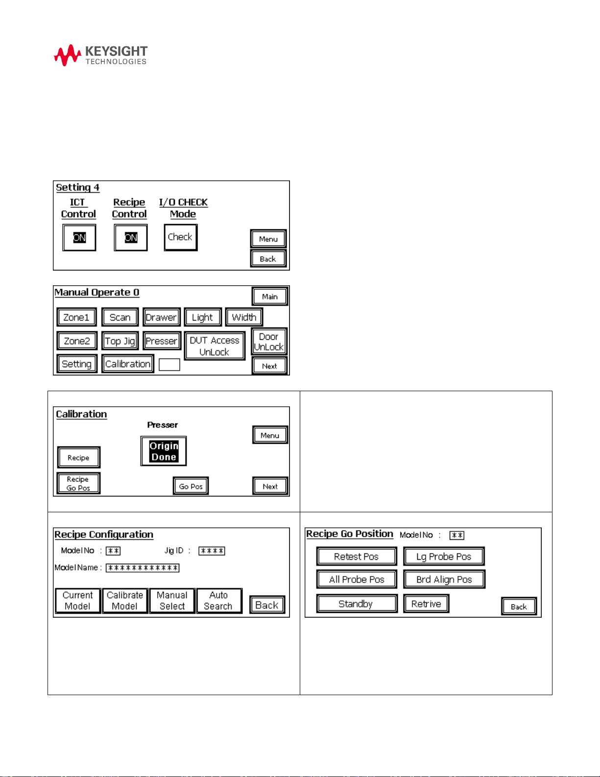
Then, initialize the Press to “Origin Done”, select “Recipe” to
enter into “Recipe Configuration”
Select “Recipe Go Pos” to enter “Recipe Go Position” to
validate Press profiles.
Current Model - view the existing Press height profiles in
detail.
Calibrate Model - Adjust Press Height profile
Manual Select - manually select Press Height profile
Auto Search – Automatically select Press Height profile based
on Top Jig ID
Validate Press positioning
Appendix:
1. 50 recipe profiles for unique fixture ID and Press height
This feature is also known as Recipe control, in short. There are a total of 50 memory profiles and each
memory profile can store a unique fixture ID along with its Press height positions. To use this, set Recipe
Control to ON at Setting 4.
To calibrate the Press height profile, goto Maintenance -> Calibration
Page 3
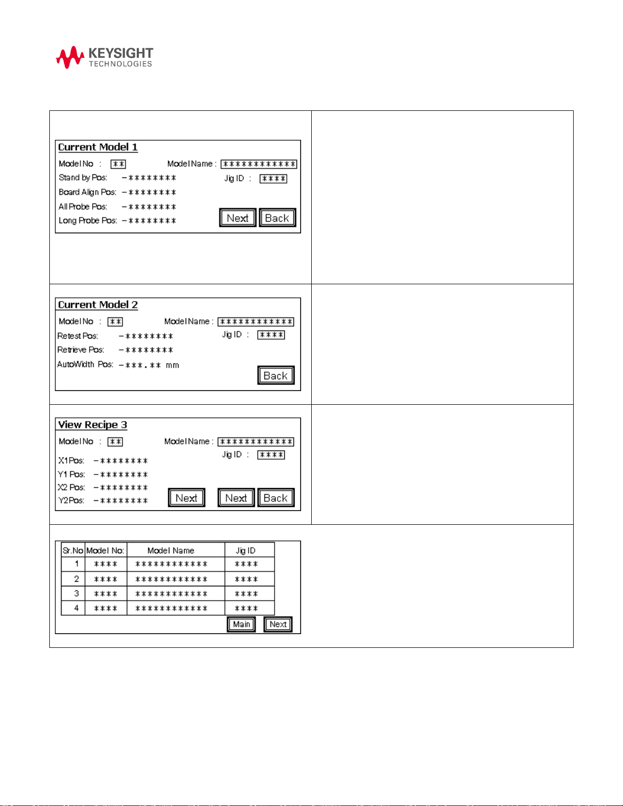
Select Current Model
Model No: Series numbering from 01 – 50
Model Name: Project or Product name
Jig ID: Top fixture ID or Autofile
Standby Pos: Position of the Press when idling, to allow board
transfer between zones
Board Align Pos: Position of the Press when verifying if the
board is seated properly on the tooling pin and support plate.
All Probe Pos: Position of the Press where board is in contact
with all probes for analog and digtal in-circuit testing.
Long Probe Pos: Position of the Press where board is in
contact with the long probes only.
Next: Go to next page
Back: Back to previous page
Retest Pos: Position of the Press where board doesn’t contact
any probes. Like Press Off.
Retrieve Pos: Position of the Press where fixture is safe to
remove for maintenance.
Autowidth Pos: Position of the conveyor width where board
can tranfers from one zone to another zone.
X1 Pos: 1st X-axis position for scanning a barcode.
Y1 Pos: 1st Y-axis position for scanning a barcode.
X2 Pos: 2nd X-axis position for scanning a barcode.
Y2 Pos: 2nd Y-axis position for scanning a barcode.
Select Calibrate Model
From the table listed above, select a location to store the Press profile. Recipe Setting 1 Page will show up.
Page 4

Select Jig ID, model Name, Standby Pos, Board Align Pos,
All Probe Pos, Long Probe Pos, Retest Pos, Retrieve Pos and
etc to store all the desired parameters.
Select YES at Save all Setting to save all parameters to
memory.
Select No at Save all Setting will discard all parameters
memory.
This page will appear when Jig ID is selected
Jig ID Current Installed: Top fixture ID detected
Top Jig ID Save to Model: Enter Autofile that matches the top
fixture ID.
This page will appear when Model Name is selected
Model Name: Enter Project or Product Name
Page with various positioning naming will appear when
selected
Standby Pos: Board Align Pos: All Probe Pos:
Long Probe Pos: Retest Pos: Retrieve Pos
Previous: Old Press Position saved in memory
New: New Press position to be saved in memory
Current: Existing Press Position being jogged
Set: Set Existing Press position as New position in memory
Select Search Origin to move the Press to the start
position.
Select and hold Up+ or Down– to manually jog the
Page 5

Press to the desired position
Use Slow to slow down the Press movement if needed.
Select Set to save the desired Press position to memory.
A table page will appear when “Manual Select” is selected.
Select “Next” to scroll to next page.
Select “Main” to scroll back to Recipe Configuration page.
Select a row that is associated with JIG ID to manually load
and use the profile.
Model selection screen pop-out. Review and select
Yes: Accept and use Jig ID
No: Reject and Exit
Select “Chg. Jig” button to enter to “Change Fixture” screen
Lock: Secure the Top and Bottom fixture clamp
Unlock: Press auto jog to Retrieve position, Unlock Top and
bottom fixture clamp.
Auto Search: Automatically select Press Height profile based
on Top Jig ID
Main: Back to Main Page
2. Ability to load/unload fixture in one single step
3. Display of Fixture ID at Production Mode
Page 6

I/O Check: Check sensors, board stoppers reed switch,
SMEMA and etc
Press NonByPass/Press ByPass: Bypassing Press to allow
board transfer without testing. Example: link conveyor
Reset: Raise the Press to Retrieve position and eject the board
if present in zone 2.
Press Position
Address Byte
Read Byte
Standby Position
D5402+D5401
4
Board Align Position
D5404+D5403
4
All Probe Position
D5406+D5405
4
Long Probe Position
D5408+D5407
4
Retest Position
D5410+D5409
4
Retrieve Position
D5412+D5411
4
AutoWidth Position
D5414+D5413
4
Model No
D5400
2
Model Name
D5435+D5434+D5433+D5432+D5431+D5430
12
Jig ID
D5438
2
4. Read Press Positions and Error Codes from Computer
Here is the listing of PLC addresses used to read the Press positions.
An example of the subroutine to verify the position is also shown below.
!##############################################################
sub Check_Press_Height
global Using_BtBasic
! This routine is to check the Press height
print using "@"
print "Reading Press Height from PLC"
Read_Address1$ = "5401" !Standby LSB
Read_Address2$ = "5402" !Standby MSB
Read_Address3$ = "5403" !Board Align LSB
Read_Address4$ = "5404" !Board Align MSB
call Read_PLC (Read_Address1$, Read_Data1$)
call Read_PLC (Read_Address2$, Read_Data2$)
Page 7

Address
ERROR ID
Message
D7500
#1
Unable to Turn ON Zone1 Stopper.
D7500
#2
Unable to Turn OFF Zone1 Stopper.
D7500
#4
## Not in Use ##
D7500
#8
Unable to Turn Off Zone2 Stopper
D7500
#10
Unable to Turn ON Zone2 Stopper
D7500
#20
## Not in Use ##
D7500
#40
Board Jam at Zone1 Conveyor
D7500
#80
Board Jam at Zone2 Conveyor
D7500
#100
Board Zone1 to Zone2 Transfer Error
D7500
#200
Double Board Error ,Zone1 to Zone2 Transfer Error
D7500
#400
## Not in Use ##
D7500
#800
Unable to Move Press, Zone2 Entry or Exit Sensor triggered
D7500
#1000
Drawer Up Error
D7500
#2000
Drawer Down Error
D7500
#4000
Top Jig Lock Error
D7500
#8000
Top Jig UnLock Error
D7501
#1
Bottom Jig Lock Error
D7501
#2
Bottom Jig UnLock Error
D7501
#4
Press Home Move Error
D7501
#8
Lower Limit Trigger while Press Move
D7501
#10
Upper Limit Trigger while Press Move
D7501
#20
Board Orientation Error
D7501
#40
## Not in Use ##
D7501
#80
## Not in Use ##
D7501
#100
## Not in Use ##
D7501
#200
## Not in Use ##
call Read_PLC (Read_Address1$, Read_Data3$)
call Read_PLC (Read_Address2$, Read_Data4$)
Standby_Pos$= Read_Data2$&Read_Data1$
Board_Align_Pos$= Read_Data4$&Read_Data3$
print "Standby Position is: "; hti(Standby_Pos$)
print "Standby Position is: "; hti(Board_Align_Pos$)
subend
!##############################################################
User also can read the Error flag with following address and data byte.
Page 8

D7501
#400
## Not in Use ##
D7501
#800
## Not in Use ##
D7501
#1000
## Not in Use ##
D7501
#2000
## Not in Use ##
D7501
#4000
## Not in Use ##
D7501
#8000
## Not in Use ##
D7502
#1
NC Card Error
D7502
#2
Servo Driver Error
D7502
#4
Servo Motor Brake Error
D7502
#8
## Not in Use ##
D7502
#10
Right Side Drawer Not Down while trying to move.
D7502
#20
Front Safety Hook Not Release while trying to move Press
D7502
#40
Board Manually Removed during Auto Mode. Restart
D7502
#80
Left Side Drawer not down while trying to move
D7502
#100
Rear Safety Hook Not Release while Trying to move Press
D7502
#200
Board Without status present at Zone2
D7502
#400
Scanner Timeout - No feedback signal
D7502
#800
ICT Timeout - No feedback signal
D7502
#1000
Jig Height Error
D7502
#2000
Bottom Jig Not Lock While Moving Press
D7502
#4000
Top Jig Not Lock While Moving Press
D7502
#8000
Maintenance Key is ON While Auto Mode
D7503
#1
Top JIG Not Fully IN Error While Press Move
D7503
#2
Bottom Jig Not In While Press Move
D7503
#4
Engine Not Detect
D7503
#8
## Not in Use ##
D7503
#10
Demo Mode Conveyor Reverse Error.Z2 to Z1 Error
D7503
#20
Safety Hook Not Unlock While Auto Mode
D7503
#40
Press Retest position Error
D7503
#80
## Not in Use ##
D7503
#100
## Not in Use ##
D7503
#200
## Not in Use ##
D7503
#400
## Not in Use ##
D7503
#800
## Not in Use ##
D7503
#1000
## Not in Use ##
D7503
#2000
## Not in Use ##
D7503
#4000
## Not in Use ##
D7503
#8000
Board Present at Zone2 Exit
D7504
#1
## Not in Use ##
D7504
#2
## Not in Use ##
D7504
#4
## Not in Use ##
Page 9

D7504
#8
## Not in Use ##
D7504
#10
## Not in Use ##
D7504
#20
Zone2 DC Motor Driver Error
D7504
#40
## Not in Use ##
D7504
#80
## Not in Use ##
D7504
#100
## Not in Use ##
D7504
#200
Board Not Clear on Conveyor While Auto Mode
D7504
#400
Board Not Clear on Conveyor While AutoWidth
D7504
#800
DUT Access not Lock While Auto
D7504
#1000
Board Alignment Check Error
D7504
#2000
## Not in Use ##
D7504
#4000
## Not in Use ##
D7504
#8000
## Not in Use ##
D7505
#1
Missing Model Number While Auto Mode
D7505
#2
Missing Model Name While Auto Mode
D7505
#4
Actual Jig ID Not Matching Jig ID selected While Auto Mode
D7505
#8
Standby Position No Value While Auto Mode
D7505
#10
Board Align Position No value While Auto Mode
D7505
#20
All Probe Position No value While Auto Mode
D7505
#40
Long Probe Position No Value While Auto Mode
D7505
#80
Retest Position No Value While Auto Mode
D7505
#100
Retrieve Position No Value While Auto Mode
D7505
#200
Auto Width No Value While Auto Mode
D7505
#400
## Not in Use ##
D7505
#800
## Not in Use ##
D7505
#1000
## Not in Use ##
D7505
#2000
## Not in Use ##
D7505
#4000
## Not in Use ##
D7505
#8000
Double Board Error.
5. Other Enhancements:
1. Press movement is slower now using Go position validation at Debug and Calibration
2. MCB3 no longer tripped if initializing Autowidth
3. Enhance Auto mode error message with details steps
4. Buzzer is computer controllable with autocode of Address#3004 and Data#0004.
5. Downstream timeout is optional
6. System re-starting Auto mode will check board present in zone 1 and zone 2.
7. All settings are relocated to Setting pages from 1-4.
8. Fixed Autowidth Reset to 60 mm in Maintenance mode.
Page 10

© Keysight Technologies, Inc. 2014
Printed in Malaysia 07/2014
 Loading...